RENMARK AERODROME MASTER PLAN - Renmark ... CRITICAL AIRPORT PLANNING PARAMETERS .....6 5.1 Forecast...
28
RENMARK AERODROME MASTER PLAN November 2016 Adopted – 22 November 2016
Transcript of RENMARK AERODROME MASTER PLAN - Renmark ... CRITICAL AIRPORT PLANNING PARAMETERS .....6 5.1 Forecast...
RENMARK AERODROME
MASTER PLAN
November 2016
Adopted – 22 November 2016
1 INTRODUCTION ............................................................................................................................................. 3 1.1 Overview of the Airport ................................................................................................................................ 3 1.2 Purpose and Objectives of the Master Plan ............................................................................................. 3 1.3 Methodology and Consultation ................................................................................................................. 3 1.4 Report Structure ............................................................................................................................................. 3 2 MASTER PLAN CONTEXT ............................................................................................................................... 3 2.1 Historical Background ................................................................................................................................... 3 2.2 Regional Context ........................................................................................................................................... 4 2.3 Socio-Economic Context ............................................................................................................................. 4 2.4 Regulatory Context ....................................................................................................................................... 4 2.5 Policy Context ................................................................................................................................................ 4 2.6 Previous and Current (Master) Plans .......................................................................................................... 4 2.7 Key Stakeholders ........................................................................................................................................... 4 3 CURRENT SITUATION ...................................................................................................................................... 4 3.1 Ownership and Management .................................................................................................................... 4 3.2 Site Description ............................................................................................................................................... 5 3.3 Surrounding Land........................................................................................................................................... 5 3.4 Existing Activities ............................................................................................................................................ 5 3.5 Existing Facilities ............................................................................................................................................. 5 3.6 Ground Transport Access ............................................................................................................................. 6 3.7 Utility Services ................................................................................................................................................. 6 3.8 Environmental Values ................................................................................................................................... 6 3.9 Heritage Values ............................................................................................................................................. 6 4 STRATEGIC VISION AND OBJECTIVES .......................................................................................................... 6 4.1 Strategic Vision ............................................................................................................................................... 6 4.2 Objectives ....................................................................................................................................................... 6 5 CRITICAL AIRPORT PLANNING PARAMETERS .............................................................................................. 6 5.1 Forecast of Future Operations ..................................................................................................................... 6 5.2 Selected Design Aircraft............................................................................................................................... 8 5.3 Runway configuration .................................................................................................................................. 9 5.4 Obstacle Limitation Surface ...................................................................................................................... 12 5.5 Navigation Systems ..................................................................................................................................... 13 5.6 Aviation Support and Landside Facilities ................................................................................................ 13 5.7 Airspace Protection Surfaces .................................................................................................................... 14 5.8 Aircraft Noise ................................................................................................................................................ 14 5.9 Environmental and Heritage Sites ............................................................................................................ 17 6 LAND USE PLAN ........................................................................................................................................... 17 6.1 Land Use Precincts ...................................................................................................................................... 17 6.2 Land Use Precinct Guidelines .................................................................................................................... 18 7 FACILITY DEVELOPMENT PLAN ................................................................................................................... 20 7.1 Movement Area Facilities .......................................................................................................................... 20 7.2 Aviation Support Facilities .......................................................................................................................... 21 8 GROUND TRANSPORT PLAN ....................................................................................................................... 22 9 ENVIRONMENTAL MANAGEMENT PLAN (EMP) ........................................................................................ 22 10 HERITAGE MANAGEMENT PLAN (HMP) ..................................................................................................... 22 11 AIRPORT SAFEGUARDING PLAN ................................................................................................................ 22 11.1 National Airports Safeguarding Framework (NASF) .............................................................................. 22 11.2 Airspace Protection Surfaces .................................................................................................................... 24 11.3 Aircraft Noise Contours ............................................................................................................................... 24 11.4 Planning Policies and Controls .................................................................................................................. 24 12 IMPLEMENTATION PLAN ............................................................................................................................. 25 13 DRAWINGS .................................................................................................................................................. 27 13.1 20 year Master Plan and Ultimate Layout ............................................................................................... 27 13.2 Obstacle Limitation Surface (OLS) Planning ........................................................................................... 28 Annexure A – Community Value of Regional Airports of South Australia
1. INTRODUCTION
This Master Plan has been prepared in accordance with guidelines set by the Planning and
Transport Policy section of the South Australian Department of Planning, Transport and
Infrastructure.
1.1. Overview of the Airport
The Town of Renmark located 214 km northeast of Adelaide (258km by road). The Airport is
located 7km southwest of the Town of Renmark. The airport consists of a 2 runway layout
with an additional glider natural surface strip.
1.2 Purpose and Objectives of the Master Plan
The key objectives of the Master Plan are:
a) provide an easily understood planning framework to cover both the aviation and
non aviation development over the next 20 years;
b) to ensure development is logical, cost effective and enhances aviation safety;
c) to ensure future development has minimal adverse impact on the environment and
the surrounding community;
d) to encourage value adding development of facilities and business ventures on the
airport.
1.3 Methodology and Consultation
This draft Master Plan has been prepared by the Aerodrome Reporting Officer in
consultation with tenants and users of the aerodrome. The draft is intended for referral to
Council and possible public display for consultation and feedback.
1.4 Report Structure
This master plan comprises 2 parts; - background information - Sections 1-3 and Master
Planning - Sections 4 onwards.
2. MASTER PLAN CONTEXT
2.1 Historical Background
The Renmark Aerodrome commenced in 1935. Originally operated as a Commonwealth
Aerodrome, it was handed over to Council in 1975. The 07/25 runway, taxiway and apron
were sealed circa 1982 along with construction of new passenger terminal in 1997. Since
that time the main pavements have remained unchanged but there has been ongoing
development of hangars and associated pavements for light aircraft and gliders.
The total area is 214 hectares.
At various times since the 1980 works, there have been Regular Passenger Transport (RPT)
services operating from Renmark with links to Adelaide and Mildura. Southern Sky Airlines
ceased operations in June 1999 resulting in the withdrawal of its services to Renmark.
O’Conner Airlines operated for a short period in 2001 and to this day Renmark remains
unserved by an RPT.
2.2 Regional Context
Renmark is the largest aerodrome between Adelaide and Mildura. Currently the narrow
width of the seal limits the opportunity to fly larger aircraft out of Renmark. Upgrading the
runway would open opportunities to a larger range of potential Regular Public Transport
aircraft services and aircraft servicing the mining sector through fly in fly out arrangements.
Council wishes to explore possible upgrades and the subsequent opportunities the airport
might bring in terms of accelerated skilling hubs, international tourism and the
establishment of a flying school.
2.3 Socio-Economic Context
The Renmark Paringa Council area is 90,000 hectares with a population of an estimated
9,882(as of 30Jun 09)
2.4 Regulatory Context
Renmark is a registered aerodrome and therefore is required to comply with Civil Aviation
Safety Authority regulations as delegated in their Manual of Standards Part 139 –
Aerodromes. The site is also contained within special purpose Airport Zone in the Renmark
Council Development Plan.
2.5 Policy Context
The continued ownership and development of the airport is supported by the Renmark
Regional Council Development Plan March 2011.
2.6 Previous and Current (Master) Plans
There have been no previous master planning studies completed for the Renmark
Aerodrome.
2.7 Key Stakeholders
Organisations and individuals with an interest in the airport include.
Renmark Flying club
Fixed base operators
Flying schools
Tenants
Companies regularly operating into Renmark
Renmark Paringa Council
Royal Flying Doctor Service
3. CURRENT SITUATION
3.1 Ownership and Management
The aerodrome is owned and operated by the Renmark Paringa Council. The aerodrome
administration is under the direction of the Director Infrastructure and Environmental
Services. There are no full time staff at the airport with various staff appointed to the role of
Aerodrome Reporting Officer and day to day maintenance.
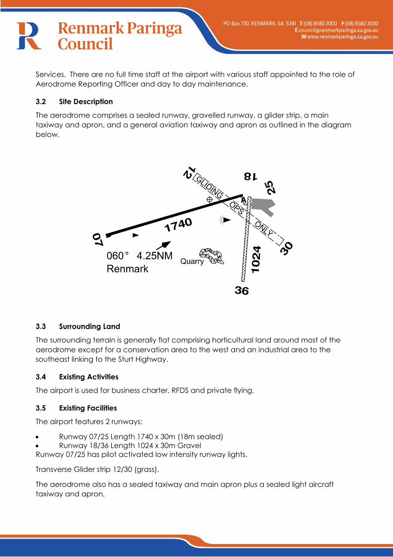
3.2 Site Description
The aerodrome comprises a sealed runway, gravelled runway, a glider strip, a main
taxiway and apron, and a general aviation taxiway and apron as outlined in the diagram
below.
3.3 Surrounding Land
The surrounding terrain is generally flat comprising horticultural land around most of the
aerodrome except for a conservation area to the west and an industrial area to the
southeast linking to the Sturt Highway.
3.4 Existing Activities
The airport is used for business charter, RFDS and private flying.
3.5 Existing Facilities
The airport features 2 runways:
Runway 07/25 Length 1740 x 30m (18m sealed)
Runway 18/36 Length 1024 x 30m Gravel
Runway 07/25 has pilot activated low intensity runway lights.
Transverse Glider strip 12/30 (grass).
The aerodrome also has a sealed taxiway and main apron plus a sealed light aircraft
taxiway and apron.
A privately owned swipe card AVGAS and Jet A-1 refuelling facility is available; a call out
fee applies.
Buildings comprise a passenger terminal, Flying Group Clubhouse and 14 hangars.
3.6 Ground Transport Access
The airport is connected via Airport Road to the Sturt Highway. The road network is sealed
and suitable for all vehicles requiring access to the airport.
3.7 Utility Services
Engineering services are available including 3 phase power, telecom and non-potable
Renmark Irrigation Trust water.
3.8 Environmental Values
There are no areas of known environmental significance on Renmark Aerodrome.
3.9 Heritage Values
There are no areas of known heritage significance on Renmark Aerodrome.
4. STRATEGIC VISION AND OBJECTIVES
4.1 Strategic Vision
The strategic vision for Renmark airport is to develop into a significant hub for the Riverland
and surrounding regions potentially providing for (a) fly in fly out operations to the mining
sector, (b) passenger services, (c) flight training and
(a) potential to service our agricultural sector.
4.2 Objectives
The key objectives for the airport are:
a) Develop an efficient, safe and compliant airport that meets community and industry
needs and expectations.
b) Encourage aviation business development particularly in regards to introduction of
Regular Public Transport, fly in fly out services, flying training, aircraft charters and
bulk cargo.
5. CRITICAL AIRPORT PLANNING PARAMETERS
5.1 Forecast of Future Operations
Currently there are no Regular Public Transport or fly in fly out (FIFO) services at Renmark.
There are two local flying instructors.
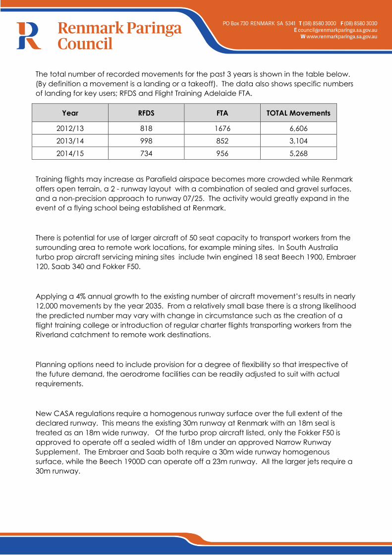
The total number of recorded movements for the past 3 years is shown in the table below.
(By definition a movement is a landing or a takeoff). The data also shows specific numbers
of landing for key users; RFDS and Flight Training Adelaide FTA.
Year RFDS FTA TOTAL Movements
2012/13 818 1676 6,606
2013/14 998 852 3,104
2014/15 734 956 5,268
Training flights may increase as Parafield airspace becomes more crowded while Renmark
offers open terrain, a 2 - runway layout with a combination of sealed and gravel surfaces,
and a non-precision approach to runway 07/25. The activity would greatly expand in the
event of a flying school being established at Renmark.
There is potential for use of larger aircraft of 50 seat capacity to transport workers from the
surrounding area to remote work locations, for example mining sites. In South Australia
turbo prop aircraft servicing mining sites include twin engined 18 seat Beech 1900, Embraer
120, Saab 340 and Fokker F50.
Applying a 4% annual growth to the existing number of aircraft movement’s results in nearly
12,000 movements by the year 2035. From a relatively small base there is a strong likelihood
the predicted number may vary with change in circumstance such as the creation of a
flight training college or introduction of regular charter flights transporting workers from the
Riverland catchment to remote work destinations.
Planning options need to include provision for a degree of flexibility so that irrespective of
the future demand, the aerodrome facilities can be readily adjusted to suit with actual
requirements.
New CASA regulations require a homogenous runway surface over the full extent of the
declared runway. This means the existing 30m runway at Renmark with an 18m seal is
treated as an 18m wide runway. Of the turbo prop aircraft listed, only the Fokker F50 is
approved to operate off a sealed width of 18m under an approved Narrow Runway
Supplement. The Embraer and Saab both require a 30m wide runway homogenous
surface, while the Beech 1900D can operate off a 23m runway. All the larger jets require a
30m runway.
5.2 Aerodrome Reference Code System
The Airport Reference Code is described by International Civil Aviation Organisation (ICAO)
as a system that relates the characteristics of Airports to specifications that are suitable for
the aeroplanes that are intended to operate from these Airports. The code number relates
to the aeroplane reference field length, the code letter is based on the aeroplane
wingspan and outer main gear wheel span. Note that determination of the aeroplane
reference field length is solely for the selection of the code number and is not intended to
influence the actual runway length provided.
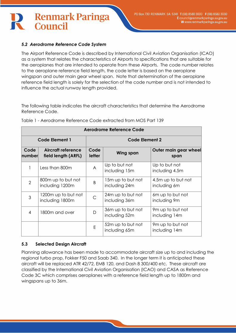
The following table indicates the aircraft characteristics that determine the Aerodrome
Reference Code.
Table 1 - Aerodrome Reference Code extracted from MOS Part 139
Aerodrome Reference Code
Code Element 1 Code Element 2
Code
number
Aircraft reference
field length (ARFL)
Code
letter Wing span
Outer main gear wheel
span
1 Less than 800m A Up to but not
including 15m
Up to but not
including 4.5m
2 800m up to but not
including 1200m B
15m up to but not
including 24m
4.5m up to but not
including 6m
3 1200m up to but not
including 1800m C
24m up to but not
including 36m
6m up to but not
including 9m
4 1800m and over D 36m up to but not
including 52m
9m up to but not
including 14m
E 52m up to but not
including 65m
9m up to but not
including 14m
5.3 Selected Design Aircraft
Planning allowance has been made to accommodate aircraft size up to and including the
regional turbo prop, Fokker F50 and Saab 340. In the longer term it is anticipated these
aircraft will be replaced ATR 42/72, EMB 120, and Dash 8 300/400 etc. These aircraft are
classified by the International Civil Aviation Organisation (ICAO) and CASA as Reference
Code 3C which comprises aeroplanes with a reference field length up to 1800m and
wingspans up to 36m.
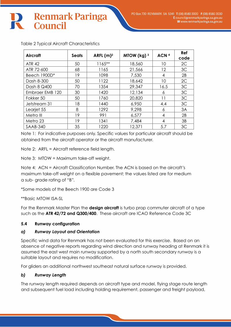
Table 2 Typical Aircraft Characteristics
Aircraft Seats ARFL (m)2 MTOW (kg) 3 ACN 4 Ref
code
ATR 42 50 1165** 18,560 10 2C
ATR 72-600 68 1165 21,566 12 3C
Beech 1900D* 19 1098 7,530 4 2B
Dash 8-300 50 1122 18,642 10 2C
Dash 8 Q400 70 1354 29,347 16.5 3C
Embraer EMB 120 30 1420 12,134 6 3C
Fokker 50 50 1760 20,820 11 3C
Jetstream 31 18 1440 6,950 4.4 3C
Learjet 55 8 1292 9,298 6 3A
Metro III 19 991 6,577 4 2B
Metro 23 19 1341 7,484 4 3B
SAAB-340 35 1220 12,371 5.7 3C
Note 1: For indicative purposes only. Specific values for particular aircraft should be
obtained from the aircraft operator or the aircraft manufacturer.
Note 2: ARFL = Aircraft reference field length.
Note 3: MTOW = Maximum take-off weight.
Note 4: ACN = Aircraft Classification Number. The ACN is based on the aircraft’s
maximum take-off weight on a flexible pavement; the values listed are for medium
a sub- grade rating of “B”.
*Some models of the Beech 1900 are Code 3
**Basic MTOW ISA-SL
For the Renmark Master Plan the design aircraft is turbo prop commuter aircraft of a type
such as the ATR 42/72 and Q300/400. These aircraft are ICAO Reference Code 3C
5.4 Runway configuration
a) Runway Layout and Orientation
Specific wind data for Renmark has not been evaluated for this exercise. Based on an
absence of negative reports regarding wind direction and runway heading at Renmark it is
assumed the east west main runway supported by a north south secondary runway is a
suitable layout and requires no modification.
For gliders an additional northwest southeast natural surface runway is provided.
b) Runway Length
The runway length required depends on aircraft type and model, flying stage route length
and subsequent fuel load including holding requirement, passenger and freight payload,
atmospheric temperature and pressure, wind speed and direction, and obstacle
clearance1.
1Regular Public Transport / air transport aircraft are required under Civil Aviation Order CAO
20.7.1.b to maintain 35ft(10.6m) terrain clearance throughout the various phases of climb
with one engine inoperative.;
Without a critical or target destination from Renmark, it is not possible to fix a precise
runway length requirement although the available length of 1740m would appear
adequate for most destinations involving turbo prop aircraft.
Examination of the available space within the airport boundary shows it is not possible to
develop additional runway length without land acquisition. For the purpose of this study it is
assumed the existing main runway length is to remain unchanged.
Similarly there is no evidence to support an extension to the existing cross runway.
c) Pavement Strength
The existing runway pavements at Renmark are unrated.
The sealed 07/25 runway has serviced previous traffic without the need for structural repair.
Some loss of shape has occurred which may be the result of excess moisture in either the
pavement base or subgrade layers due to inadequate drainage. In severe storms the
runway has been flooded for extended periods; any increase in moisture above optimum is
likely to result in a severe loss of pavement and sub-grade strength.
In preparation for catering for heavier aircraft, geotech testing was conducted in May
2013, to determine the pavement structure, the material properties and in-situ strength of
the structural layers and the underlying subgrade.
Following examination of available data Aerodrome Design Pty Ltd prepared a suggested
reconstruction methodology to widen and strengthen the existing 07/25 main runway to
cater for F50 / Q400 wheel loads.
The suggested works are to remove the existing seal, reshape, tyne and roll the existing
base, place an additional 200mm fine crushed rock layer over the full 30m width of the
runway. Works should include a re-design of the runway and runway strip geometrics to
give improved drainage capability and reduced maintenance work in the flank areas.
The same reconstruction procedure would also apply to the taxiway and apron. In areas
where an increase in finished pavement level will create problems with drainage or access,
a 100mm asphalt overlay on the existing seal would be considered as a viable alternative
to pavement reconstruction.
A heavy 14/7mm prime and 2 coat spray would be applied to the finished surface and
finally line marked after a short period.
The estimated cost for the work assumes a 200mm FCR layer. Additional testing may prove
the sub-grade CBR to be higher than 6 but in any case the minimum practical fine crushed
rock added should not be less than 150mm.
The cost estimate is included in Section 12 of this Master Plan.
Runway 18/36 is gravelled and constructed to an unknown strength. It has been used for
many years without showing evidence of structural defect. The runway is envisaged to
remain a Code 2 runway catering for smaller planes in a cross wind situation. The
pavement strength is considered suitable for this ongoing use and should only require
regular dragging and rolling with an occasional resheet at a frequency of not less than 10
years.
The sealed main taxiway shows evidence of loss of strength and will require maintenance
repairs and strengthening in the longer term to cater for any significant increase in aircraft
wheel loads. Similar improvements will be needed to the main apron, the actual scope
and extent of works will be the subject of further geotechnical testing.
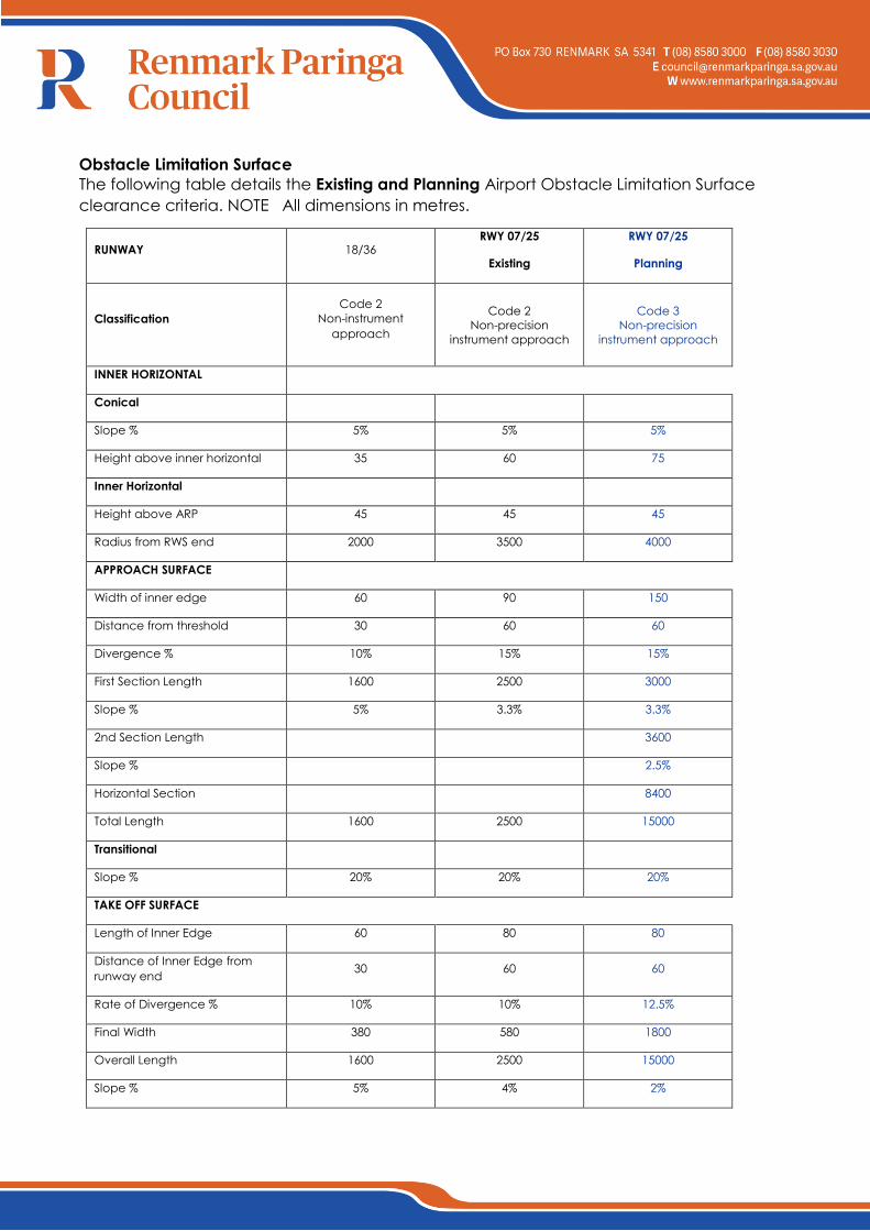
Obstacle Limitation Surface
The following table details the Existing and Planning Airport Obstacle Limitation Surface
clearance criteria. NOTE All dimensions in metres.
RUNWAY 18/36 RWY 07/25
Existing
RWY 07/25
Planning
Classification
Code 2
Non-instrument
approach
Code 2
Non-precision
instrument approach
Code 3
Non-precision
instrument approach
INNER HORIZONTAL
Conical
Slope % 5% 5% 5%
Height above inner horizontal 35 60 75
Inner Horizontal
Height above ARP 45 45 45
Radius from RWS end 2000 3500 4000
APPROACH SURFACE
Width of inner edge 60 90 150
Distance from threshold 30 60 60
Divergence % 10% 15% 15%
First Section Length 1600 2500 3000
Slope % 5% 3.3% 3.3%
2nd Section Length 3600
Slope % 2.5%
Horizontal Section 8400
Total Length 1600 2500 15000
Transitional
Slope % 20% 20% 20%
TAKE OFF SURFACE
Length of Inner Edge 60 80 80
Distance of Inner Edge from
runway end 30 60 60
Rate of Divergence % 10% 10% 12.5%
Final Width 380 580 1800
Overall Length 1600 2500 15000
Slope % 5% 4% 2%
Navigation Systems
Renmark currently has a Global Navigation Satellite System GNSS (GPS) non-precision
approach to the thresholds of runway 07 and 25.
The Council owned Non Directional Beacon was decommissioned 2015 as part of the Air
Services Australia rationalization of navaid programme where from 2016 the primary means
of navigation in Australia will be via the Global Navigation Satellite System (GNSS).
Aviation Support and Landside Facilities
a) Passenger Terminal
The existing terminal comprises passenger waiting lounge, offices for airlines and Council,
toilets etc. The terminal is separated from the apron by a car park. The current facility
would appear adequate for the time frame of this master plan although some increased
security arrangements may be required as discussed below.
b) Security Requirements
Current security regulations do not require specific passenger or baggage screening for
closed charter aircraft operations. Where charters are open to the public and involve
aircraft with a maximum weight in excess of 20 tonnes, dedicated screening areas are
mandatory.
Within the next 20 years, there is a possibility security requirements may become more
demanding, for example a requirement to screen passenger and baggage on closed
charter flights. While there is no evidence this will occur, it would be prudent to ensure any
development of the terminal and car park allow for possible introduction of security
facilities.
Other future security changes may require for example provision of additional lighting,
security cameras and CCTV monitoring, security fencing, controlled access gates,
controlled of access through buildings etc.
For aerial work flying training and private flying there is currently no mandatory requirement
security screening of control. In the very long term such activities may need to be
segregated from passenger aircraft operations, similar to what occurs at security controlled
airports today. At Renmark the separation of the private hangar area from the passenger
terminal apron will allow ease of segregation if ever required.
c) Refuelling facilities
The location of the existing refuelling facilities is considered consistent with long term
planning objectives. Additional space has been set aside in this master plan to provide for
expanded storage if required.
d) Aircraft hangars
The relatively large numbers of hangars, currently 14, accommodates private aircraft used
for business and recreational flying including gliders.
The current hangar location has allowance for duplication of the structures. Planning
controls on future expansion will be needed to ensure development is compatible with the
use of the 12/30 glider strip.
e) Meteorological facilities
The existing Bureau of Meteorology (BoM) facilities at Renmark including Terminal area
forecast TAF Category D are to be retained. The facility currently comprises an automatic
weather station AWS, but has no ceilometer or visibility meter.
The BoM completed the Review of Aerodrome Forecast Services for the Aviation Industry
Final Report September 2014. The report identified the airport would continue to supply
Terminal Aircraft Forecasts (TAF). Renmark has been retained as significant/strategic TAF
location in national network (contributes to improve the efficiency of the network of TAF
service).
5.7 Airspace Protection Surfaces
Protection of airspace involves the provision of an obstacle limitation surface (OLS) plan
and protections of Procedures of Air Navigation Operations PANS-OPS surfaces.
Forming part of this master plan is the preparation of plans showing OLS and PANS ops
protection for the 07/25 and 18/36 runways. Runway 12/30 is yet to be surveyed
5.8 Aircraft Noise
a) Australian Noise Exposure Forecasts
At capital city and major centres, information on aircraft noise at airports has been
provided using Australian Noise Exposure Forecasts (ANEF). Modelling of aircraft activity is
used to produce ANEF noise contours which identify restriction of land uses in certain ANEF
zones, according to the sensitivity of the nominated land use.
The Australian Standard AS 2021 Acoustics-Aircraft Noise Intrusion-Building Siting and
Construction lists various land uses (e.g. houses through to heavy industrial areas)
considered acceptable/unacceptable within the various ANEF contours. The
recommended ANEF zones for residential development are shown in the following table
extracted from AS 2021.
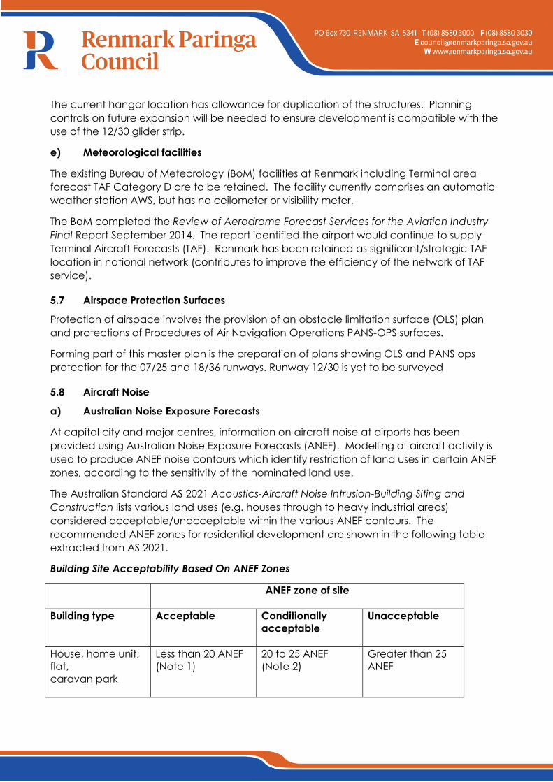
Building Site Acceptability Based On ANEF Zones
ANEF zone of site
Building type
Acceptable
Conditionally
acceptable
Unacceptable
House, home unit,
flat,
caravan park
Less than 20 ANEF
(Note 1)
20 to 25 ANEF
(Note 2)
Greater than 25
ANEF
NOTES:
1. The actual location of the 20 ANEF contour is difficult to define accurately, mainly
because of variation in aircraft flight paths.
2. Within the 20 ANEF to 25 ANEF, some people may find that the land is not
compatible with residential or educational uses. Land use authorities may consider that the
incorporation of noise control features in the construction of residences or schools is
appropriate. Ref AS 2021-2000
b) Single Event Contours
Because the ANEF is a summation of the total noise over an average day, when applied at
aerodromes with small numbers of aircraft movements the results are less than satisfactory,
in that the ANEF contours barely go beyond the extent of the airport, whereas it is known
aircraft noise will be heard over a far greater area and will, in some situations, be
considered intrusive.
Even with higher rates than expected it is unlikely Renmark would receive more than 4
flights per day by larger 18- 50 seat aircraft. This low level of activity would be insufficient to
push the area covered by the ANEF contours to effectively describe the areas subject to
potential noise intrusion. This would still be the case even if the number of predicted
movements were increased well above the likely growth rate.
An alternative is to plot the aircraft noise as a single noise level event contour,
superimposed on the aircraft flight paths. Typically the 70 dB(A) contour is the benchmark
used in studies undertaken by Commonwealth Department of Transport and Infrastructure,
as it is equivalent to a single event level of 60dB(A) specified in the Australian Standard
2021, as the accepted indoor design sound level for normal domestic dwellings. (An
external single noise event will be attenuated by approximately 10 dB(A) by the fabric of a
house with open windows) An internal noise level above 60 dB(A) is likely to interfere with
conversation or listening to the television.
The following data obtained from AS 2021 provides noise levels appropriate for a particular
building site and number of aircraft operations.
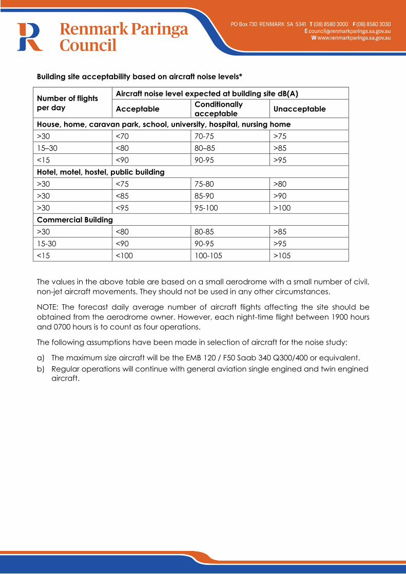
Building site acceptability based on aircraft noise levels*
Number of flights
per day
Aircraft noise level expected at building site dB(A)
Acceptable Conditionally
acceptable Unacceptable
House, home, caravan park, school, university, hospital, nursing home
>30 <70 70-75 >75
15–30 <80 80–85 >85
<15 <90 90-95 >95
Hotel, motel, hostel, public building
>30 <75 75-80 >80
>30 <85 85-90 >90
>30 <95 95-100 >100
Commercial Building
>30 <80 80-85 >85
15-30 <90 90-95 >95
<15 <100 100-105 >105
The values in the above table are based on a small aerodrome with a small number of civil,
non-jet aircraft movements. They should not be used in any other circumstances.
NOTE: The forecast daily average number of aircraft flights affecting the site should be
obtained from the aerodrome owner. However, each night-time flight between 1900 hours
and 0700 hours is to count as four operations.
The following assumptions have been made in selection of aircraft for the noise study:
a) The maximum size aircraft will be the EMB 120 / F50 Saab 340 Q300/400 or equivalent.
b) Regular operations will continue with general aviation single engined and twin engined
aircraft.
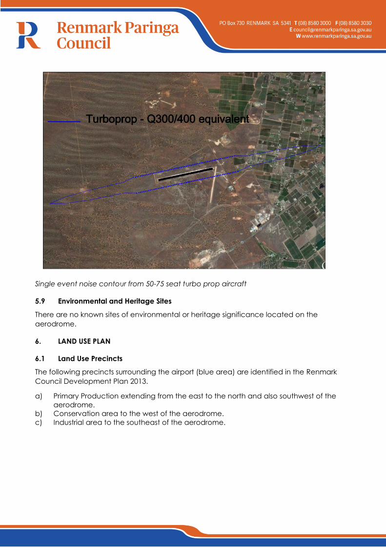
Single event noise contour from 50-75 seat turbo prop aircraft
5.9 Environmental and Heritage Sites
There are no known sites of environmental or heritage significance located on the
aerodrome.
6. LAND USE PLAN
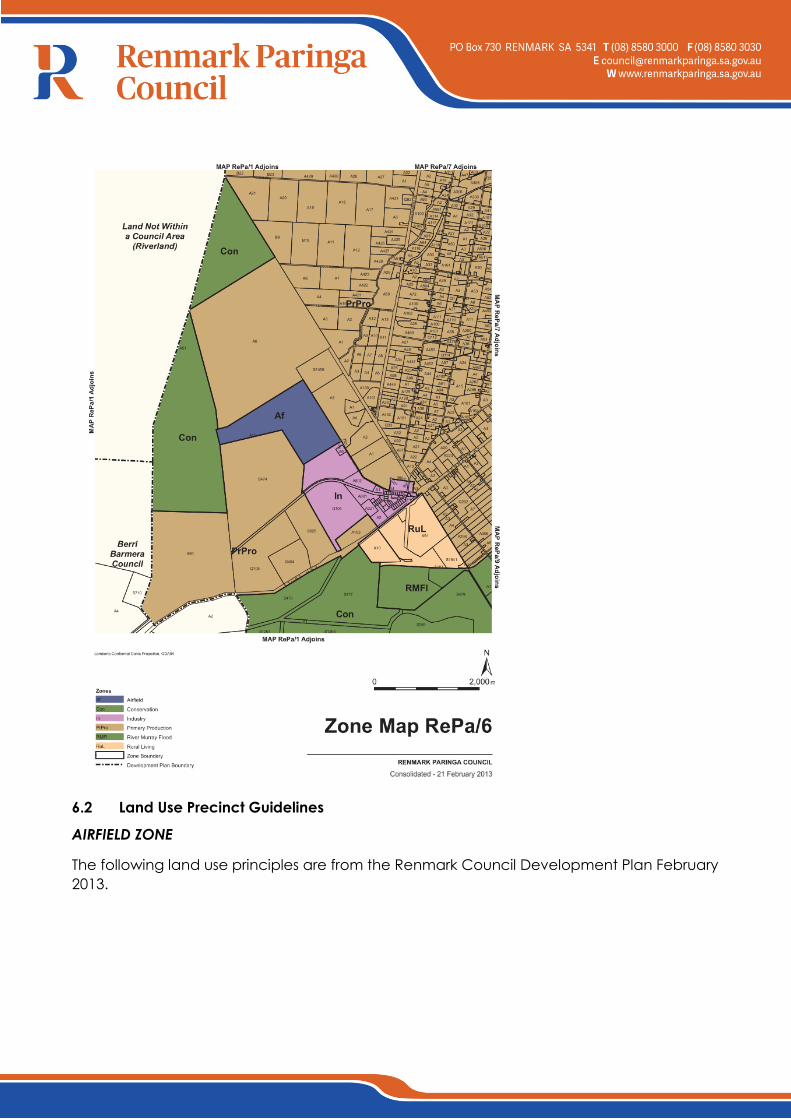
6.1 Land Use Precincts
The following precincts surrounding the airport (blue area) are identified in the Renmark
Council Development Plan 2013.
a) Primary Production extending from the east to the north and also southwest of the
aerodrome.
b) Conservation area to the west of the aerodrome.
c) Industrial area to the southeast of the aerodrome.
6.2 Land Use Precinct Guidelines
AIRFIELD ZONE
The following land use principles are from the Renmark Council Development Plan February
2013.
a) Objectives of the Airfield Zone
1. A zone primarily accommodating aircraft operations, passenger terminals,
airport and aviation-related light industrial, service industrial, warehouse and
storage purposes.
2. Development that contributes to the desired character of the zone.
b) Principles Of Development Control - Airfield Zone
1. The following forms of development are envisaged in the zone:
air passenger or air freight terminal
aircraft related facility
airport
fuel depot
light industry ancillary to and in association with aviation activities
service industry ancillary to and in association with aviation activities
shop within the terminal building
warehouse ancillary to and in association with aviation activities.
2. Development listed as non-complying is generally inappropriate.
3. Development should not impede the use of the zone for aviation purposes.
4. Development that would be adversely affected by noise and other hazards
caused by airport activities should not be undertaken in the zone.
5. Development should not be undertaken unless it is consistent with the desired
character for the zone.
6. Commercial and light industrial development located on the airport site should:
facilitate the more efficient operation of the airport
be sited in defined clusters
not adversely affect the amenity of surrounding land uses.
7. Land should not be divided unless it is required to facilitate the more efficient
operation of the Renmark Aerodrome.
BUILDING NEAR AIRFIELDS
a) Objectives
1. Development that ensures the long-term operational, safety and commercial
aviation requirements of airfields (airports, airstrips and helicopter landing sites)
continue to be met.
2. b) Principles Of Development Control
1. The height and location of buildings and structures should not adversely affect
the long-term operational, safety and commercial aviation requirements of
airfields.
2. Buildings and structures should not be developed unless a safety analysis
determines that the building/structure does not pose a hazard to aircraft
operations.
3. Development in the vicinity of airfields should not create a risk to public safety, in
particular through any of the following:
lighting glare
smoke
air turbulence
storage of flammable liquids
attraction of birds
materials that affect aircraft navigational aids.
4. Lighting within 6 kilometres of an airport should be designed so that it does not
pose a hazard to aircraft operations.
5. Development that is likely to increase the attraction of birds should not be
located within 3 kilometres of an airport used by commercial aircraft. If located
closer than 3 kilometres the facility should incorporate bird control measures to
minimise the risk of bird strikes to aircraft.
6. Dwellings should not be located within areas affected by airport noise.
7. Development within areas affected by aircraft noise should be consistent with
Australian Standard AS2021 - Acoustics - Aircraft Noise Intrusion - Building Siting
and Construction.
7. FACILITY DEVELOPMENT PLAN
7.1 Movement Area Facilities
a) Runways and runway strips
The existing 07/25 sealed runway is 1740m long 30m wide, sealed to 18m. To meet the
demands of the targeted critical aircraft the pavement sealed width will need to be
widened to 30m. The pavement strength will also need improving pending on (a) the
specific critical aircraft and (b) the results of geotechnical examination. Increasing the
strength can involve removal of the existing seal and placing additional crushed rock or
simular material and resealing with for example a prime and 2 or 3 coat bituminous seal.
This will involve closure of the runway for the duration of the works.
An alternative is to apply a strengthening asphalt overlay. This option has the advantage
that the work can be conducted at night and the aerodrome can remain open during the
day.
For night operations by Code 3 aircraft the runway strip would be widened from 90m to
150m. Only the central 90m width would need to be graded, the outer 30m along each
side is required to conform to flyover standard. Subject to survey confirmation, available
data suggests this could be achieved relatively easily.
The southern perimeter fence that runs parallel to 07/25 will probably infringe the 1 in 7 side
transition clearance from the widened runway strip. The extent (if any) of a possible
infringement will need to be determined by survey. The results would then need to be
analysed to determine what impact if any the fence places on long term operations.
The existing 18/36 gravel runway is 1024m long. There are no considerations within the
scope of this master plan to lengthen this facility.
b) Taxiways, taxilanes
Main taxiway A connects the eastern end of 07/25 and connects to the terminal apron
area traversing the north end of runway 18/36. Whilst not considered ideal in having a
requirement to cross an active runway, the airport configuration does not allow a simpler
arrangement.
The anticipated levels of aircraft activity do not support consideration for a future parallel
taxiway. Consideration to a passing bay on Taxiway A between runway 18/36 and the
intersection of the general aviation is included to allow more efficient aircraft access and
egress to both runways.
c) Aprons, aircraft parking areas
The existing apron is of sufficient space to cater for any likely increase in aircraft size and or
numbers. Adjacent areas to the northwest and southwest should be preserved for future
apron expansion,
Plans have been prepared to duplicate the existing general aviation apron to double the
aircraft and hangar space availability. If further development beyond this is needed
consideration to relocation and realignment of new runway to replace both 18/36 and
12/30 is an option for consideration in the long term as shown in the drawings
d) Lighting
The existing lighting on runway 07/25 will need to be upgraded to the current standard (i.e.
60m runway edge spacing) for non-precision approach runways when the lighting is either
replaced or the runway upgraded i.e. lengthened.
Similarly runway end and threshold lights would also be replaced. Confirm with Standards
at the time.
The taxiway lighting has also changed since installation and will require replacement /
upgrading in the future.
Apron areas used at night will require floodlighting to the new illumination standards for
those areas used regularly at night.
7.2 Aviation Support Facilities
This Master Plan has included provision for the following aviation related facilities:
1. Passenger terminal
2. Fuel facilities
3. Aircraft hangars
4. Aircraft maintenance support facilities
5. Meteorological facilities
6. Flying training school
In the case where there is a larger than expected demand for hangar space and aircraft
parking, an ultimate planning layout has been prepared that allows duplication of a 3rd
and 4th row of hangars linked to a much larger apron area and spatial allocation for a
large support complex possibly a flying training college. The expanded airfield
arrangement is shown in the Ultimate Layout drawing in Section 13.
8. GROUND TRANSPORT PLAN
The current road network to the airport is consistent with the long term development and
required no major upgrade or change.
The airport configuration allows access to all buildings via existing external roads. No
additional roadworks are considered necessary within the next 20 years.
9. ENVIRONMENTAL MANAGEMENT PLAN (EMP)
There are no known sites of environmental significance within the aerodrome boundary. It
follows that development of an EMP would be to ensure activities on airport e.g. storage
handling and use of aviation fuels, aircraft maintenance etc must be undertaken in a
manner that does not adversely impact on air, soil or water (surface and ground water).
10. HERITAGE MANAGEMENT PLAN (HMP)
At this stage a HMP has not been prepared on the basis that there are no known sites of
archaeological or heritage significance within the aerodrome boundary.
11. AIRPORT SAFEGUARDING PLAN
11.1 National Airports Safeguarding Framework (NASF)
The National Airports Safeguarding Framework is a national land use planning framework
that aims to:
a) improve community amenity by minimising aircraft noise-sensitive developments near
airports; and
b) improve safety outcomes by ensuring aviation safety requirements are recognised in
land use planning decisions through guidelines being adopted by jurisdictions on
various safety-related issues.
The National Airports Safeguarding Advisory Group (NASAG), comprising of
Commonwealth, State and Territory Government planning and transport officials, the
Australian Government Department of Defence, the Civil Aviation Safety Authority (CASA),
Airservices Australia and the Australian Local Government Association (ALGA), has
developed the National Airports Safeguarding Framework (the Framework).
The National Airports Safeguarding Framework was developed to provide guidance for
Planners to consider potential impact of developments outside the airport on airport
operations. Principles of the guideline will be considered in local planning processes when
assessing a development application in the vicinity of Renmark Aerodrome. The purpose of
the framework is to enhance the current and future safety, viability and growth of aviation
operations at Australian airports, by supporting and enabling:
a) the implementation of best practice in relation to land use assessment and decision
making in the vicinity of airports;
b) assurance of community safety and amenity near airports;
c) better understanding and recognition of aviation safety requirements and aircraft
noise
d) impacts in land use and related planning decisions;
e) the provision of greater certainty and clarity for developers and land owners;
f) improvements to regulatory certainty and efficiency; and
g) the publication and dissemination of information on best practice in land use and
related planning that supports the safe and efficient operation of airports.
NASF PRINCIPLES
Principle 1. The safety, efficiency and operational integrity of airports should be protected
by all governments, recognising their economic, defence and social significance.
Principle 2. Airports, governments and local communities should share responsibility to
ensure that airport planning is integrated with local and regional planning.
Principle 3. Governments at all levels should align land use planning and building
requirements in the vicinity of airports.
Principle 4. Land use planning processes should balance and protect both airport/aviation
operations and community safety and amenity expectations.
Principle 5. Governments will protect operational airspace around airports in the interests
of both aviation and community safety.
Principle 6. Strategic and statutory planning frameworks should address aircraft noise by
applying a comprehensive suite of noise measures.
Principle 7. Airports should work with governments to provide comprehensive and
understandable information to local communities on their operations concerning noise
impacts and airspace requirements.
NASF GUIDELINES
Over the long term, inappropriate development around airports can result in unnecessary
constraints on airport operations and negative impacts on community amenity due to the
effects of aircraft noise. These impacts need to be managed in a balanced and
transparent way.
Guideline A provides advice on the use of a complementary suite of noise metrics, to
inform planners and provide communities with comprehensive and understandable
information about aircraft noise.

Guideline B presents a layered risk approach to the siting and design of buildings near
airport runways to assist land use planners and airport operators to reduce the risk of
building - generated windshear and turbulence. It also provides options to modify existing
buildings.
Guideline C provides advice to help protect against wildlife hazards originating off-airport
through appropriate land use planning decisions and the way in which existing land use is
managed in the vicinity of airports.
Guideline D provides advice on the location and safety management of wind turbines and
other similar structures which can constitute a risk to low-flying aviation operations and can
also affect the performance of Communications, Navigation equipment operated by
Airservices Australia.
Guideline E provides advice on ensuring lighting in the vicinity of airports is not configured
so as to cause distraction or confusion to pilots
Guideline F provides advice for planners and decision makers about working within and
around protected airspace, including obstacle limitation surface (OLS) and Procedures for
Air Navigation Services (PANS-OPS) intrusions, and how these can be better integrated into
local planning processes.
11.2 Airspace Protection Surfaces
Obstacle Limitation Surface Plan.
An airport OLS has been developed for Renmark for the protection of the 3 runways. The
OLS plans are in 2 forms Exiting and Future to cover both the existing and long term.
Procedures for Air Navigation Services – Aircraft Operations PANS OPS
Renmark has straight in approach Area Navigation Global Navigation Satellite System
(RNAV GNSS) procedures for runways 07 and 25. The clearance surfaces associated with
these procedures are covered by the OLS parameters.
There has been no inclusion of GPS approaches for the 18/36 or 12/30 runways.
11.3 Aircraft Noise Contours
Australian Noise Exposure Forecasts have not been prepared for Renmark on the basis that
the frequency of aircraft movements and the type of aircraft flying are not sufficient to
generate a meaningful ANEF even using the most optimistic forecasts. Instead single event
noise contours have been generated using modelling data for aircraft types typically using
Renmark.
11.4 Planning Policies and Controls
The existing planning policies and controls contained in the Renmark Council Development
Plan February 2013 are consistent with the controls contained in the NASF guidelines.
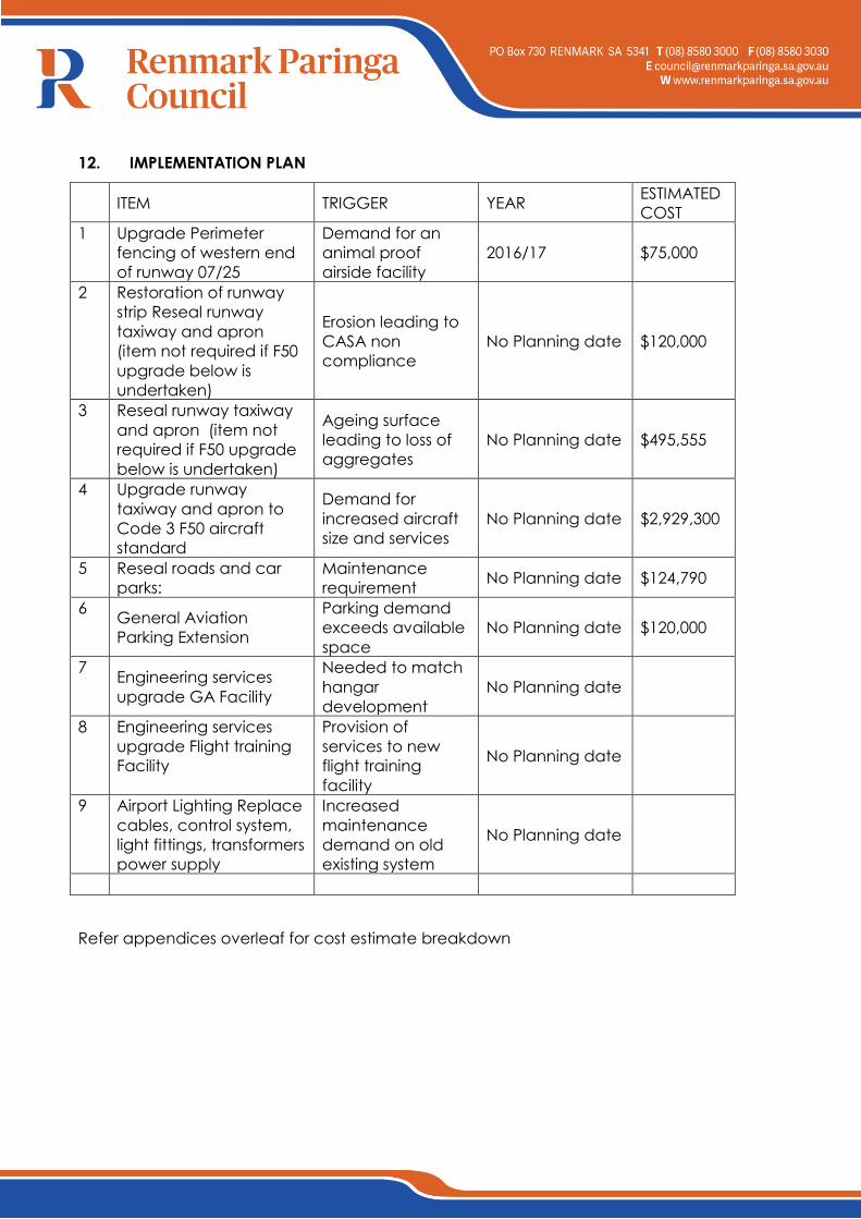
12. IMPLEMENTATION PLAN
ITEM TRIGGER YEAR
ESTIMATED
COST
1 Upgrade Perimeter
fencing of western end
of runway 07/25
Demand for an
animal proof
airside facility
2016/17 $75,000
2 Restoration of runway
strip Reseal runway
taxiway and apron
(item not required if F50
upgrade below is
undertaken)
Erosion leading to
CASA non
compliance
No Planning date $120,000
3 Reseal runway taxiway
and apron (item not
required if F50 upgrade
below is undertaken)
Ageing surface
leading to loss of
aggregates
No Planning date $495,555
4 Upgrade runway
taxiway and apron to
Code 3 F50 aircraft
standard
Demand for
increased aircraft
size and services
No Planning date $2,929,300
5 Reseal roads and car
parks:
Maintenance
requirement No Planning date $124,790
6 General Aviation
Parking Extension
Parking demand
exceeds available
space
No Planning date $120,000
7 Engineering services
upgrade GA Facility
Needed to match
hangar
development
No Planning date
8 Engineering services
upgrade Flight training
Facility
Provision of
services to new
flight training
facility
No Planning date
9 Airport Lighting Replace
cables, control system,
light fittings, transformers
power supply
Increased
maintenance
demand on old
existing system
No Planning date
Refer appendices overleaf for cost estimate breakdown
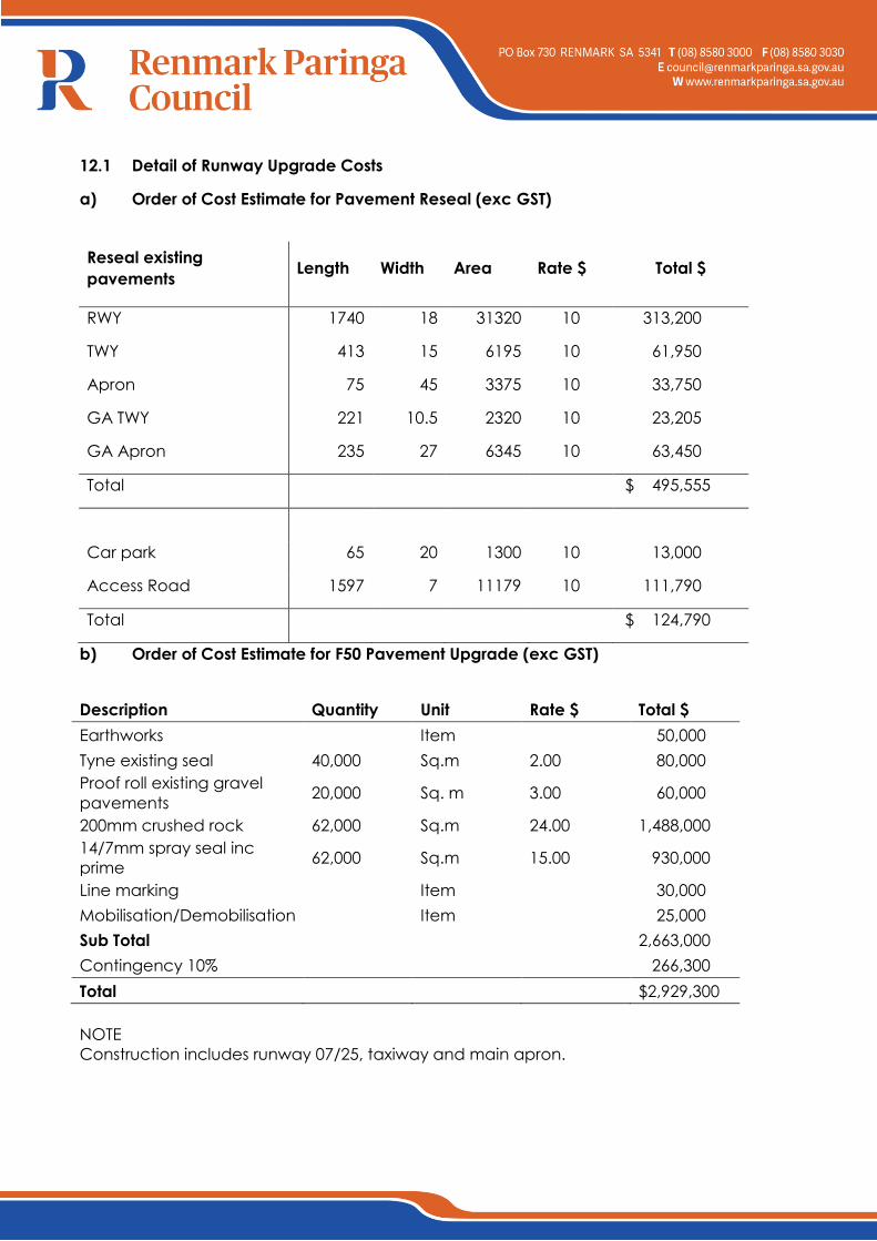
12.1 Detail of Runway Upgrade Costs
a) Order of Cost Estimate for Pavement Reseal (exc GST)
Reseal existing
pavements Length Width Area Rate $ Total $
RWY 1740 18 31320 10 313,200
TWY 413 15 6195 10 61,950
Apron 75 45 3375 10 33,750
GA TWY 221 10.5 2320 10 23,205
GA Apron 235 27 6345 10 63,450
Total
$ 495,555
Car park 65 20 1300 10 13,000
Access Road 1597 7 11179 10 111,790
Total
$ 124,790
b) Order of Cost Estimate for F50 Pavement Upgrade (exc GST)
Description Quantity Unit Rate $ Total $
Earthworks Item 50,000
Tyne existing seal 40,000 Sq.m 2.00 80,000
Proof roll existing gravel
pavements 20,000 Sq. m 3.00 60,000
200mm crushed rock 62,000 Sq.m 24.00 1,488,000
14/7mm spray seal inc
prime 62,000 Sq.m 15.00 930,000
Line marking Item 30,000
Mobilisation/Demobilisation Item 25,000
Sub Total 2,663,000
Contingency 10% 266,300
Total $2,929,300
NOTE
Construction includes runway 07/25, taxiway and main apron.
13. DRAWINGS
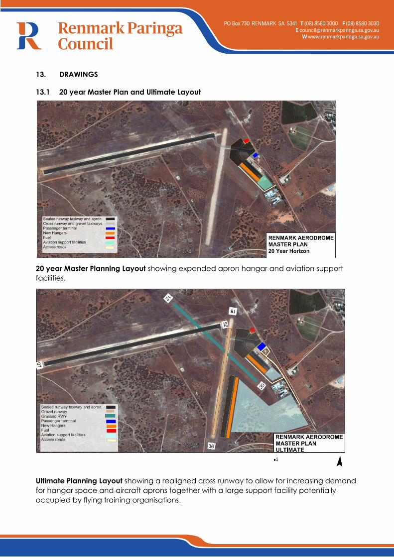
13.1 20 year Master Plan and Ultimate Layout
20 year Master Planning Layout showing expanded apron hangar and aviation support
facilities.
Ultimate Planning Layout showing a realigned cross runway to allow for increasing demand
for hangar space and aircraft aprons together with a large support facility potentially
occupied by flying training organisations.
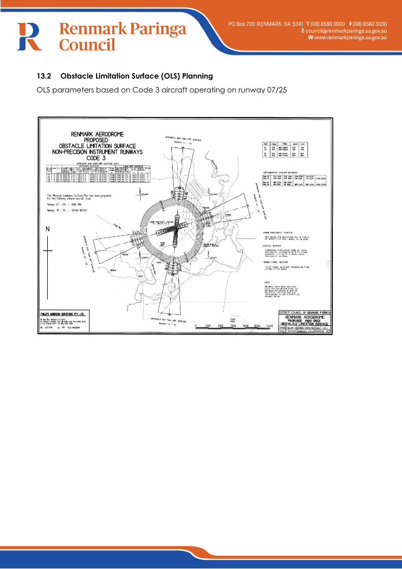
13.2 Obstacle Limitation Surface (OLS) Planning
OLS parameters based on Code 3 aircraft operating on runway 07/25