Remote racking operating instructions - Eaton
24
Contents Description Page Introduction 2 Getting started 2 Learn Mode 3 Normal operation 4 Error conditions 4 Factory reset condition 5 Connections to the RemRack unit 5 Updating the operational program 5 Appendix A 6 Appendix B 21 Appendix C 24 Effective August 2017 Supersedes October 2012 Instructional Leaflet IL02400003E Remote racking operating instructions
Transcript of Remote racking operating instructions - Eaton

ContentsDescription Page
Introduction . . . . . . . . . . . . . . . . . . . . . . . . . . . . . . . . . . . . . . . . . . . . . . . . . . . . . . . . . . . . . . . . . . . . . . . . . 2Getting started . . . . . . . . . . . . . . . . . . . . . . . . . . . . . . . . . . . . . . . . . . . . . . . . . . . . . . . . . . . . . . . . . . . . . . . 2Learn Mode . . . . . . . . . . . . . . . . . . . . . . . . . . . . . . . . . . . . . . . . . . . . . . . . . . . . . . . . . . . . . . . . . . . . . . . . . 3Normal operation . . . . . . . . . . . . . . . . . . . . . . . . . . . . . . . . . . . . . . . . . . . . . . . . . . . . . . . . . . . . . . . . . . . . . 4Error conditions . . . . . . . . . . . . . . . . . . . . . . . . . . . . . . . . . . . . . . . . . . . . . . . . . . . . . . . . . . . . . . . . . . . . . . 4Factory reset condition . . . . . . . . . . . . . . . . . . . . . . . . . . . . . . . . . . . . . . . . . . . . . . . . . . . . . . . . . . . . . . . . 5Connections to the RemRack unit . . . . . . . . . . . . . . . . . . . . . . . . . . . . . . . . . . . . . . . . . . . . . . . . . . . . . . . . 5Updating the operational program . . . . . . . . . . . . . . . . . . . . . . . . . . . . . . . . . . . . . . . . . . . . . . . . . . . . . . . . 5Appendix A . . . . . . . . . . . . . . . . . . . . . . . . . . . . . . . . . . . . . . . . . . . . . . . . . . . . . . . . . . . . . . . . . . . . . . . . . 6Appendix B . . . . . . . . . . . . . . . . . . . . . . . . . . . . . . . . . . . . . . . . . . . . . . . . . . . . . . . . . . . . . . . . . . . . . . . . 21
Appendix C . . . . . . . . . . . . . . . . . . . . . . . . . . . . . . . . . . . . . . . . . . . . . . . . . . . . . . . . . . . . . . . . . . . . . . . . 24
Effective August 2017Supersedes October 2012Instructional Leaflet IL02400003E
Remote racking operating instructions

2
Instructional Leaflet IL02400003EEffective August 2017
Remote racking operating instructions
EATON CORPORATION www.eaton.com
IntroductionThe RemRack controller consists of a motor, gearbox, and electronic controller that is used to automatically move a circuit breaker between the CONNECTED position (breaker fully seated on the stabs) and the TEST position (breaker removed safely from the stabs) . The RemRack motor, gearbox, and electronic controller are all housed in a custom steel bracket that is installed on the front of the breaker . A square shaft on the rear of the RemRack assembly engages the lead screw that is used to “rack” the breaker in (toward the CONNECTED position) and “rack” the breaker out (toward the TEST position) . When the RemRack motor shaft is turning “clockwise” (when viewed from the front of the breaker), the breaker is racking in (toward the CONNECTED position) . When the RemRack motor shaft is turning “counterclockwise” (when viewed from the front of the breaker), the breaker is racking out (toward the TEST position) . An included handheld “pendant” controller is used to control the RemRack unit . The pendant controller has two buttons: IN and OUT . The IN button is pressed to move the breaker to the CONNECTED position and the OUT button is pressed to move the breaker to the TEST position . (Additional controllers are available to operate this device . Contact Eaton for details .)
Remote Racking System
Getting startedA separate installation document provides instructions for field installation of the RemRack unit on the breaker. Please see Appendix A.
The RemRack unit has the following features .
LED status indicators—There are five (5) LED status indicators located on the front of the RemRack panel:
1. POWER ON—This green LED is illuminated to indicate that AC power is applied to the RemRack . This green LED is also used to indicate error conditions by flashing a specific number of times (see "Error conditions" section on Page 4).
2. BREAKER CONNECTED—This green LED is illuminated when the breaker is at the CONNECTED position .
3. BREAKER AT TEST—This yellow LED is illuminated when the breaker is at the TEST position .
4. BREAKER IN MOTION—This red LED is illuminated any time that the breaker is in motion . This LED illuminates when the motor is running in either the IN or the OUT direction .
5. LEARN MODE—This yellow LED is illuminated when the Learn Mode is active . The Learn Mode LED is also used to indicate the RemRack firmware version number at power up . When the power is applied to the RemRack unit, the Learn Mode LED will flash to indicate the firmware version number: One flash indicates version 1; two flashes indicate version 2; three flashes indicate version 3, etc .
NOTETHE MANUAL RACKING POSITION IS PROVIDED FOR EMERGENCY ONLY. THE CM-52 IS DESIGNED TO BE ELECTRICALLY TESTED IN THE “TEST” POSITION. MOVEMENT TO THE DISCONNECT POSITION IS NOT REQUIRED UNLESS A BREAKER IS NEEDED TO BE PHYSICALLY REMOVED FROM THE ENCLOSURE. IF A BREAKER IS RACKED OUT MANUALLY TO THE DISCONNECT POSITION, A RE-LEARNING PROCESS MAY BE REQUIRED. PLEASE SEE “LEARN MODE” ON PAGE 3. NEVER USE THE REMOTE RACKING MANUAL CRANK TO CRANK THE BREAKER TO THE “CONNECT” POSITION. DOING THIS WOULD EXERT FORCE ON THE CLUTCH MECHANISM AND CAUSE THE CLUTCH NOT TO DISENGAGE.
WARNINGFAILURE TO MANUALLY OPEN THE BREAKER AFTER THE BREAKER IS WITHDRAWN TO THE DISCONNECT POSITION AND IF THE BREAKER IS INADVERTENTLY PUSHED BACK INTO THE CELL WHILE THE BREAKER IS IN A CLOSED STATE, COULD RESULT IN SERIOUS INJURY OR DEATH.
The breaker can be manually “racked” in or out using the wrench stored on the inside of the network protector door .
NOTETHE ELECTRICAL REMOTE RACKING HARNESS SHOULD BE UNPLUGGED BEFORE USING THE EMERGENCY MANUAL RACKING PROVISION. DISCONNECT THE PLUG ON THE BOTTOM OF THE REMOTE RACKING DEVICE.
To manually rack the breaker, it is necessary to access the 5/16" female hex fitting on the end of the RemRack motor shaft . For safety reasons, this fitting is covered with a Red safety cover . A 3/8" square drive x 5/16" hex bit adapter is provided with each RemRack unit so that the wrench end will fit into the 5/16" female hex fitting on the motor shaft . To manually rack the breaker, install the hex bit adapter on the end of the wrench and insert the 5/16" hex bit into the end of the motor shaft . Push in on the wrench to disengage the RemRack spring-loaded motor clutch and turn the wrench clockwise (to rack IN toward the TEST position) or counterclockwise (to rack OUT toward the TEST position) . When manual racking is completed, release the forward pressure on the wrench that was used to disengage the spring-loaded motor clutch and slowly turn the motor shaft until the spring-loaded motor clutch pops out (indicating that the shaft is properly engaged) . Close the hinged safety cover and tighten the spanner security screw to hold the safety cover in the closed position .

3
Instructional Leaflet IL02400003EEffective August 2017
Remote racking operating instructions
EATON CORPORATION www.eaton.com
Learn Mode pushbutton
The Learn Mode pushbutton is pressed to enter the Learn Mode . There are two black nylon hole plugs located on the top of the RemRack housing . Remove the smaller one (toward the left side of the RemRack housing) to access the Learn Mode pushbutton .
Programming Port access
There are two black nylon hole plugs located on the top of the RemRack housing . Remove the larger one (near the center of the RemRack housing) to access the Programming Port . The Programming port is used only if it becomes necessary to update the firmware in the RemRack controller (this is not typical) . See the section on "Updating the operational program" on Page 5 .
Manual Status flag window
On the front right side of the RemRack unit is a rectangular cutout that is used to view the mechanical status flag on the front of the breaker . There is a white LED light on when breaker is OPEN and remote racking unit is powered provided in the RemRack to facilitate viewing of the mechanical status flag in low-light conditions . This mechanical flag is used as a visual verification that the breaker is in the CONNECTED position (red flag) or the TEST position (yellow flag) .
When the RemRack unit has been installed according to the installation instructions (see separate installation instructions), the power can be applied to the RemRack unit . The RemRack unit is shipped in the “Factory Reset” condition . When the power is first applied, the following sequence of events will occur:
1. The POWER ON LED will be illuminated .
2. The Learn Mode LED will flash to indicate the version of the firmware in the RemRack controller . When the power is applied to the RemRack unit, the Learn Mode LED will flash to indicate the firmware version number: One flash indicate version 1; two flashes indicate version 2; three flashes indicate version 3, etc .
3. The BREAKER AT TEST and BREAKER CONNECTED LEDs will both be illuminated . Because this is a disallowed condition (the breaker cannot be at the CONNECTED and TEST positions at the same time), it was chosen as an indication that the RemRack controller is in the “Factory Reset” mode, does not know the location of the CONNECTED or TEST positions, and that the Learn Mode must be run to “program” the RemRack controller with these parameters .
From the “Factory Reset” condition, the Learn Mode can be run . Refer to the “Learn Mode” section for instructions .
Learn Mode (standard version) - effective August 1, 2017 RemRacks will be Auto Learn, see Appendix C.BE SURE THAT THE TRANSFORMER IS DE-ENERGIZED BEFORE PERFORMING ANY OF THESE INSTRUCTIONS.
When the RemRack unit is first installed on a breaker, it is necessary for the RemRack controller to “learn” the location of the BREAKER AT TEST position . This position is identified and stored in the RemRack controller’s non-volatile memory as a specified number of shaft revolutions from the BREAKER CONNECTED position . A typical value for the BREAKER AT TEST position is approximately 19 revolutions (in the counterclockwise direction) from the BREAKER CONNECTED position .
Prior to operation of the RemRack unit, the operator must use the Learn Mode to initialize the RemRack controller with the location of the BREAKER AT TEST position .
WARNINGPRIOR TO ENTERING THE LEARN MODE, VERIFY THAT THE BREAKER IS CLEAR TO MOVE BECAUSE THE MOTOR WILL ACTIVATE AND BEGIN ROTATING THE LEAD SCREW IMMEDIATELY UPON ENTRY INTO THE LEARN MODE.
To enter the Learn Mode, the breaker must be cranked to “TEST” position, then remove the small black nylon hole plug on the top of the RemRack housing and press the small pushbutton that is located inside the access hole . DO NOT USE A METAL OBJECT TO PRESS THE PUSHBUTTON. IT MAY ENTER THE REMRACK HOUSING AND CONTACT HIGH VOLTAGE. Immediately after the Learn Mode pushbutton is pressed, the motor will start moving as follows:
1. The motor will begin by turning the lead screw in the counter-clockwise direction (breaker is racking OUT) and will run in that direction for two revolutions of the motor shaft . During this operation, the BREAKER IN MOTION LED indicator will be illuminated .
otee:N This step racks out the breaker for two revolutions in case the breaker happens to already be located at (or very near to) the CONNECTED position .
2. The motor will stop and then reverse and begin turning the lead screw in the clockwise direction (breaker is racking IN) . During this operation, the BREAKER IN MOTION LED indicator will be illuminated . The motor will continue to rack the breaker IN (toward the BREAKER CONNECTED position) until the breaker reaches the BREAKER CONNECTED position . Note that the speed and sound of the motor may change as the breaker moves onto the stabs . When the breaker reaches the CONNECTED position, the Learn Mode LED will “blink” three times (to indicate that the CONNECTED position has been memorized) and the controller will recognize and “memorize” this shaft position as the CONNECTED position (the motor will stop momentarily) . After a very short delay, the motor will reverse and begin turning the lead screw in the counterclockwise direction (breaker is racking OUT) . At this point, it is up to the operator to “signal” the RemRack controller when the breaker reaches the BREAKER AT TEST position . This is done by pressing the Learn Mode pushbutton when the mechanical flag on the breaker is centered on the YELLOW indication (the mechanical flag can be viewed through the rectangular cutout on the front of the RemRack unit) . When the Learn Mode pushbutton is pressed, the RemRack controller will “memorize” this shaft position as the TEST position . The Learn Mode LED will “wink” three times (to indicate that the TEST position has been memorized) . The BREAKER AT TEST LED will be illuminated, the Learn Mode LED will be turned off, and the RemRack controller will exit from the Learn Mode . At this point, the controller has “learned” (i .e ., memorized) the shaft positions that correspond to the BREAKER CONNECTED and BREAKER AT TEST positions . The RemRack is now ready for operation .
4
Instructional Leaflet IL02400003EEffective August 2017
Remote racking operating instructions
EATON CORPORATION www.eaton.com
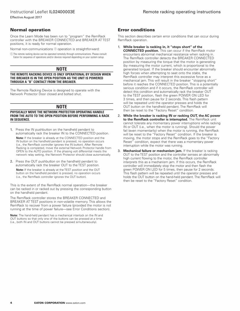
Normal operationOnce the Learn Mode has been run to “program” the RemRack controller with the BREAKER CONNECTED and BREAKER AT TEST positions, it is ready for normal operation .
Normal non-communications 1 operation is straightforward: 1 The remote racking device can be operated remotely through communications. Please consult
Eaton for sequence of operations and/or devices required depending on your system setup.
NOTETHE REMOTE RACKING DEVICE IS ONLY OPERATIONAL BY DESIGN WHEN THE BREAKER IS IN THE OPEN POSITION AS THE UNIT IS POWERED THROUGH A “B” CONTACT FROM THE BREAKER.
The Remote Racking Device is designed to operate with the Network Protector Door closed and bolted shut .
NOTEPHYSICALLY MOVE THE NETWORK PROTECTOR OPERATING HANDLE FROM THE AUTO TO THE OPEN POSITION BEFORE PERFORMING A RACK IN SEQUENCE.
1. Press the IN pushbutton on the handheld pendant to automatically rack the breaker IN to the CONNECTED position .
otee:N If the breaker is already at the CONNECTED position and the IN button on the handheld pendant is pressed, no operation occurs (i .e ., the RemRack controller ignores the IN button) . After Remote Racking is completed, move the external Network Protector handle from OPEN to the AUTO position . If the phasing volt differential meets the network relay setting, the Network Protector should close automatically .
2. Press the OUT pushbutton on the handheld pendant to automatically rack the breaker OUT to the TEST position .
otee:N If the breaker is already at the TEST position and the OUT button on the handheld pendant is pressed, no operation occurs (i .e ., the RemRack controller ignores the OUT button) .
This is the extent of the RemRack normal operation—the breaker can be racked in or racked out by pressing the corresponding button on the handheld pendant .
The RemRack controller stores the BREAKER CONNECTED and BREAKER AT TEST positions in non-volatile memory . This allows the RemRack to recover from a power failure (provided the motor is not running at the time of power failure—see Error Conditions section) .
otee:N The hand-held pendant has a mechanical interlock on the IN and OUT buttons so that only one of the buttons can be pressed at a time (i .e ., both IN and OUT buttons cannot be pressed simultaneously) .
Error conditionsThis section describes certain error conditions that can occur during RemRack operation .
1. While breaker is racking in, it “stops short” of the CONNECTED position. This can occur if the RemRack motor encounters abnormal mechanical resistance when racking in . The RemRack controller detects the BREAKER CONNECTED position by measuring the torque that the motor is generating (by measuring the motor current, which is proportional to the generated torque) . If the breaker should encounter abnormally high forces when attempting to seat onto the stabs, the RemRack controller may interpret this excessive force as a mechanical jam . This will result in the breaker “stopping short” before it reaches the CONNECTED position . This is a potentially serious condition and if it occurs, the RemRack controller will detect this condition and automatically rack the breaker OUT to the TEST position, flash the green POWER ON LED for 3 times, and then pause for 2 seconds . This flash pattern will be repeated until the operator presses and holds the OUT button on the handheld pendant . The RemRack will then be reset to the “Factory Reset” condition .
2. While the breaker is racking IN or racking OUT, the AC power to the RemRack controller is interrupted. The RemRack unit cannot tolerate any momentary power interruptions while racking IN or OUT (i .e ., when the motor is running) . Should the power fail (even momentarily) when the motor is running, the RemRack will be reset to the “Factory Reset” condition . If the breaker is moving, the motor stops and the RemRack goes to the “Factory Reset” condition, expect that there was a momentary power interruption while the motor was running .
3. Mechanical failure or mechanism jam. If the breaker is racking OUT to the TEST position and the controller senses an abnormally high current flowing to the motor, the RemRack controller interprets this as a mechanism jam . If this occurs, the RemRack controller will immediately stop the motor and then flash the green POWER ON LED for 5 times, then pause for 2 seconds . This flash pattern will be repeated until the operator presses and holds the OUT button on the hand-held pendant . The RemRack will then be reset to the “Factory Reset” condition .

5
Instructional Leaflet IL02400003EEffective August 2017
Remote racking operating instructions
EATON CORPORATION www.eaton.com
Factory reset conditionThe “Factory Reset” condition can be identified by observing that the BREAKER AT TEST and BREAKER CONNECTED LEDs are both illuminated . Because this is a disallowed condition (the breaker cannot be at the CONNECTED and TEST positions at the same time), it was chosen as an indication that the RemRack controller is in the “Factory Reset” mode, does not know the location of the CONNECTED or TEST positions, and that the Learn Mode must be run to “program” the RemRack controller with these parameters .
The RemRack controller can be manually reset to the factory configuration as follows:
1. Turn off the power to the RemRack unit .
2. Press and hold the Learn Mode pushbutton, and while depressing the Learn Mode pushbutton, turn on the power to the RemRack unit .
3. Release the Learn Mode pushbutton .
The following sequence of events will occur to confirm that the RemRack controller is in the “Factory Reset” condition:
1. The POWER ON LED will be illuminated .
2. The Learn Mode LED will flash to indicate the version of the firmware in the RemRack controller (for details, see the description above for the Learn Mode LED) .
3. The BREAKER AT TEST and BREAKER CONNECTED LEDs will both be illuminated .
During RemRack operation, certain error conditions will automatically return the RemRack to the “Factory Reset” state . See the “Error conditions” section for details .
Connections to the RemRack unitConnections to the RemRack unit are made using a 9-position, pluggable screw terminal block on the bottom of the RemRack housing . A label is placed on the front of the housing to identify the connections . These connections are defined as follows:
Pin 1. (“left-most” terminal) . 120 Vac line input voltage to the RemRack unit (HOT) .
Pin 2. 120 Vac line input voltage to the RemRack unit (NEUTRAL) .
Pin 3. COMMON wire to the handheld pendant . The handheld pendant is connected to the RemRack unit with three wires: COMMON, IN, and OUT . When the IN button is pressed on the pendant controller, a connection is made between the IN wire and the COMMON wire . When the OUT button is pressed on the pendant controller, a connection is made between the OUT wire and the COMMON wire .
Pin 4. IN wire to the handheld pendant . The handheld pendant is connected to the RemRack unit with three wires: COMMON, IN, and OUT . When the IN button is pressed on the pendant controller, a connection is made between the IN wire and the COMMON wire . When the OUT button is pressed on the pendant controller, a connection is made between the OUT wire and the COMMON wire .
Pin 5. OUT wire to the handheld pendant . The handheld pendant is connected to the RemRack unit with three wires: COMMON, IN, and OUT . When the IN button is pressed on the pendant controller, a connection is made between the IN wire and the COMMON wire . When the OUT button is pressed on the pendant controller, a connection is made between the OUT wire and the COMMON wire .
Pin 6. RemRack Status (Power On) . This is a Form-A dry contact that connects to the RemRack Common Status line (terminal block Pin 9) when the RemRack AC power is on .
Pin 7. RemRack Status (Breaker at TEST) . This is a Form-A dry contact that connects to the RemRack Common Status line (terminal block Pin 9) when the breaker is at the TEST position .
Pin 8. RemRack Status (Breaker at CONNECTED) . This is a Form-A dry contact that connects to the RemRack Common Status line (terminal block Pin 9) when the breaker is at the CONNECTED position .
Pin 9. RemRack Status (Common) . This is the common terminal used with the RemRack status lines on terminal block pins 6, 7, and 8 .
Updating the operational programThe RemRack operational program (firmware) can be updated in the field without removing the RemRack unit from the breaker . A handheld, battery operated programmer can be plugged into the Programming Port on the top of the RemRack housing . There are two black nylon hole plugs located on the top of the RemRack housing . Remove the larger one (toward the center of the RemRack housing) to access the Programming Port . The Programming Port is used only if it becomes necessary to update the firmware in the RemRack controller (this is not typical) .
6
Instructional Leaflet IL02400003EEffective August 2017
Remote racking operating instructions
EATON CORPORATION www.eaton.com
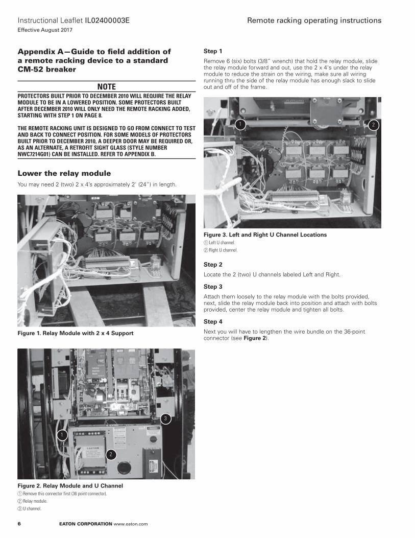
Appendix A—Guide to field addition of a remote racking device to a standard CM-52 breaker
NOTEPROTECTORS BUILT PRIOR TO DECEMBER 2010 WILL REQUIRE THE RELAY MODULE TO BE IN A LOWERED POSITION. SOME PROTECTORS BUILT AFTER DECEMBER 2010 WILL ONLY NEED THE REMOTE RACKING ADDED, STARTING WITH STEP 1 ON PAGE 8. THE REMOTE RACKING UNIT IS DESIGNED TO GO FROM CONNECT TO TEST AND BACK TO CONNECT POSITION. FOR SOME MODELS OF PROTECTORS BUILT PRIOR TO DECEMBER 2010, A DEEPER DOOR MAY BE REQUIRED OR, AS AN ALTERNATE, A RETROFIT SIGHT GLASS (STYLE NUMBER NWC7214G01) CAN BE INSTALLED. REFER TO APPENDIX B.
Lower the relay moduleYou may need 2 (two) 2 x 4’s approximately 2' (24”) in length .
Figure 1. Relay Module with 2 x 4 Support
1
2
3
Figure 2. Relay Module and U Channel1 Remove this connector first (36 point connector).
2 Relay module.
3 U channel.
Step 1
Remove 6 (six) bolts (3/8” wrench) that hold the relay module, slide the relay module forward and out, use the 2 x 4's under the relay module to reduce the strain on the wiring, make sure all wiring running thru the side of the relay module has enough slack to slide out and off of the frame .
1 2
Figure 3. Left and Right U Channel Locations1 Left U channel.
2 Right U channel.
Step 2
Locate the 2 (two) U channels labeled Left and Right .
Step 3
Attach them loosely to the relay module with the bolts provided, next, slide the relay module back into position and attach with bolts provided, center the relay module and tighten all bolts .
Step 4
Next you will have to lengthen the wire bundle on the 36-point connector (see Figure 2) .

7
Instructional Leaflet IL02400003EEffective August 2017
Remote racking operating instructions
EATON CORPORATION www.eaton.com
Step 5
Remove all 4 of the top barrier boards . Use caution, and cover open buss work with appropriate cover up .
1 1 1
1
Figure 4. Barrier Boards1 Remove.
This will expose the wire bundles’ coming from the secondary disconnects .
1
Figure 5. Secondary Disconnect Wire Bundle Exposed1 Remove.
Step 6
Remove the wire tie that holds the bundle to the insulation board .
Step 7
Next, follow the wire bundle down the side and locate the wire tie that holds it to the side panel and remove . This should give you enough slack to plug in the 36-point connector .
1
Figure 6. Wire Bundle Side Attachment1 Remove.
Step 8
Re-secure the wire bundle at the previous attachment points . Remove cover up and re-install all 4 barrier boards . This completes lowering the relay module .

8
Instructional Leaflet IL02400003EEffective August 2017
Remote racking operating instructions
EATON CORPORATION www.eaton.com
Remote racking assembly
1
2
Figure 7. Remote Racking Assembly Out of the Box (Style Number NWB2048G06)1 Remote racking assembly.
2 Hardware bag.
Figure 8. Hardware Bag
Hardware bag contents:• One shutter• One shutter stop• One 5/16" hex bit socket• Two 0 .190-32 x 0 .375 pan head screws• Three mounting blocks• Six 0 .25-20 x 0 .75 bolts• Six 0 .25 lock washers• Six 0 .25 flat washers
Tools needed:• Drill• Large and small Phillips head screwdriver• 7/16" socket with ratchet or drill driver• Large and small flat head screwdriver • Wire cutters• 7/16" wrench• Tie wrap gun• CM-52 handle
• 5/16" “T” handle
Step 1
Manually rack breaker out of the connect position to the disconnected position . (Breaker must be open!)
1
1 Lift shutter to insert crank.
1
1 Use handles to pull breaker fully out of cassette.

9
Instructional Leaflet IL02400003EEffective August 2017
Remote racking operating instructions
EATON CORPORATION www.eaton.com
Step 2
Remove breaker cover .
1
1 Loosen all four bolts.
1
1 Crank handle down and pull cover forward to remove.
Step 3
Drill holes for Remote Racking in front cover .
1
1 Make sure Remote Racking is pushed on all the way on and drill six holes in the cover.
Step 4
Mounting bracket Installation . Remove hardware from bag Install mounting brackets .
1
1 With Remote Racking removed, peel off tape backing and install brackets on inside of cover. Tighten bolts to secure brackets in place. Leave hardware in.
Step 5
Remove four breaker shutter mounting screws .
1
1 Two screws on right and two on left.
otee:N Red lock tight was used during assembly . Screws will be difficult to remove .

10
Instructional Leaflet IL02400003EEffective August 2017
Remote racking operating instructions
EATON CORPORATION www.eaton.com
Step 6
Remove shutter assembly .
1
1 With screws out, rotate entire assembly forward to remove.
Step 7
Place pin into center of fixture .
1
1 Tilt shutter bracket in order to remove.
1
1 Save front shutter cover for later re-assembly.
Step 8
Drill or grind two rivets off that hold shutter locking bracket and remove bracket .
1
1 Drill or grind off heads of rivets. May need to use chisel to pry bracket off or a punch to drive rivets out of holes.
1
1 Bracket has been removed.

11
Instructional Leaflet IL02400003EEffective August 2017
Remote racking operating instructions
EATON CORPORATION www.eaton.com
Step 9
Install shutter support bracket .
1
1 After installation, ledge may have to be pushed back. Apply green grease to front edge.
1
1 Use red LocTite on two screws.
Step 10
Install new shutter and front Indicator assembly .
Shutter installation .
1
2
1 May need to apply more green grease.
2 Tilt shutter bracket in order to remove. Reference Step 7.
1
1 Breaker indication lever must line up with indicator slot on shutter mounting assembly. If not properly aligned, breaker location will not be accurate.
Continued next page

12
Instructional Leaflet IL02400003EEffective August 2017
Remote racking operating instructions
EATON CORPORATION www.eaton.com
Step 10, continued
1
1 Reinstall four screws removed in Step 3. Use blue LocTite.
Step 11
Check shutter operation .
1
1 Using a screwdriver, lift the shutter up and down. Shutter has to move freely. Shutter must also come all the way down.
Step 12
Install cover (opposite of Step 2) .
1
1 Pull handle down and slide cover on.
1
1 Tighten four 10 mm bolts that hold cover on.

13
Instructional Leaflet IL02400003EEffective August 2017
Remote racking operating instructions
EATON CORPORATION www.eaton.com
Step 13
Remove bolts for Remote Racking .
1
1 Total of 6 bolts.
Step 14
Install Remote Racking assembly . (Continued from previous page .)
1
1 Slide lifting bracket under shutter.
1
1 Slide the Remote Racking in to place and install the mounting hardware.
1
1 Tighten the six mounting bolts.
Installation steps and checks
1. During installation of Remote Racking, the input shaft must be pushed in and rotated so that it lines up with the lev-in shaft on the CM-52 .
2. Once installed and tightened into place, rotate the “T” handle and ensure that the shaft will pop out easily .
otee:N If it does not, then try to shift the Remote Racking around till the shaft is free enough to pop out .

14
Instructional Leaflet IL02400003EEffective August 2017
Remote racking operating instructions
EATON CORPORATION www.eaton.com
Step 15
Manually run the Remote Racking into the test position .
otee:N Relay drawer must have drop down–brackets installed before moving forward and the breaker must be fully pushed into the cassette .
1
2
1 With Allen tool turn the shaft to take the breaker to the Test position.
2 Push shaft in to turn.
1
1 Run the breaker into the Test position as indicated by the breaker position indicator.
Step 16
Wiring for the Remote Racking assembly . Install bulkhead box per MI if not already installed .
1
2
1 Bulk head entry.
2 Relay drawer entry.
1
1 Route wires to inside of relay drawer. Follow existing bundle of wires.
otee:N Bulk head diagrams should now be in the # BULK#### format .

15
Instructional Leaflet IL02400003EEffective August 2017
Remote racking operating instructions
EATON CORPORATION www.eaton.com
Step 17
Per the correct bulkhead connection diagram, install the inline fuse holder and cut remote racking cord wires to correct length .
1
2
1 Line up fuse holder close to the center of DIN rail to get correct wire length.
2 Center remote racking cord wires up with fuse holder to get proper exit position from harness.
1
1 From fuse holder to end of wires should be 26".
Step 18
Continue to finish wire connections per bulkhead diagram and relay drawer connection diagram . (Aux switch contact and remote racking terminal block connection .)
1
1 Aux switch wire. Check connection diagram for placement on DIN rail.
1
1 Check remote racking/bulkhead connection for terminal block wire connection.
Step 19
Plug remote racking terminal block up to remote racking .
1
1 Be sure to double check color code wire connections.
Step 20
Connect power and control cords to Bulkhead terminal block .
1
1 Connect power and pendant leads per bulkhead connection diagram.

16
Instructional Leaflet IL02400003EEffective August 2017
Remote racking operating instructions
EATON CORPORATION www.eaton.com
Step 21
With remote racking and bulkhead connected/wired, power up circuit and start programming . Breaker must be open and in Test position .
1
1 With unit powered, power on LEDs should be illuminated.
1
1 Remove small cap and depress button start programming. Learn Mode LED will illuminate.
Breaker must be open and in Test position .
1
1 When breaker indicator is fully yellow, depress program button on top.
1. Once you depress the learn button the remote racking will automatically move into the connected position . LEDs (Power On), (Breaker in Motion), and (Learn Mode) will be illuminated .
2. Once the breaker is fully in the connected position it will then come out . Note that you must watch position indicator to verify that the red field (Connected) is fully covered . LEDs (Power On), (Breaker in Motion) and (Learn Mode) will be illuminated .
3. Once the breaker starts to rack back out, look for the yellow field (Test Position) to be fully covered . Once the breaker is in the test position, push the Learn button as in step 20 . LEDs (Power On) and (Breaker At Test) will be illuminated .
4. Once remote racking is set, operate the unit with the handheld pendant . Verify that the unit fully goes into the connected position and then back out to test .
5. Final step is to close the breaker manually to ensure the remote racking LEDs go off . If LEDs remain illuminated, then check auxiliary switch wiring . The remote racking must not work if the breaker is closed .

17
Instructional Leaflet IL02400003EEffective August 2017
Remote racking operating instructions
EATON CORPORATION www.eaton.com
Available accessories
1. Remote Racking Assembly . Part # NWB2048G06
2. Remote Racking Assembly with Two Button Pendant . Part # NWB2048G07
3. VaultGard Control Box . Part # NASO330G51
4. Remote Racking and ARM activation switch (Controls up to six Remote Racking Systems) . Part # NASO520G03
Remote Racking Pendant Power Cable (Style Number NWA9004G01)
5. Digital Input Module (used for monitoring Remote Racking status “TEST and CONNECT") via the VaultGard . Part # DIM
6. Digital Relay Accessory Module (used for controlling the Remote Racking) via the VaultGard . Part # DRAM
7. Stack Light (indicates ARM ON/OFF, Breaker CLOSED/OPEN, Breaker position CONNECTED/TEST) . Part # SL-100-5
Continued next page

18
Instructional Leaflet IL02400003EEffective August 2017
Remote racking operating instructions
EATON CORPORATION www.eaton.com
8. ARM and Stack Light Control wiring .
Continued next page

19
Instructional Leaflet IL02400003EEffective August 2017
Remote racking operating instructions
EATON CORPORATION www.eaton.com
9. Remote Racking Control Wiring .

20
Instructional Leaflet IL02400003EEffective August 2017
Remote racking operating instructions
EATON CORPORATION www.eaton.com
10. Bulkhead Part # NFX0012G07 . 11. Retrofit Sight Glass Part # NWC7214G01 .

21
Instructional Leaflet IL02400003EEffective August 2017
Remote racking operating instructions
EATON CORPORATION www.eaton.com
Appendix B—Installation of retrofit sight glass assembly (NWC7214G01)Replacing viewing window on Eaton CM-52 network protector for remote racking clearance
Step 1
Remove the nuts and washers from the window on the inside of the door .
Step 2
Remove the steel holding ring and gasket (if stuck, a gentle twist from a larger flathead screwdriver helps) .
Step 3
Remove the sight glass and gaskets (a rubber mallet from the exterior of the door can be used to remove the sight glass) .
Step 4
To eliminate any lingering clearance, use a hammer to remove the bottom two threaded studs .

22
Instructional Leaflet IL02400003EEffective August 2017
Remote racking operating instructions
EATON CORPORATION www.eaton.com
Step 5
Lay out the new stainless steel window as so:
Retrofit Window Assembly Layout

23
Instructional Leaflet IL02400003EEffective August 2017
Remote racking operating instructions
EATON CORPORATION www.eaton.com
Step 6
From the interior of the door, insert the new base with the gasket between it and the door through existing hole .
Gasket Against Door
Step 7
On exterior of door, place new gasket around threaded base, then steel washer, then tighten down steel ring .
Gasket on Door Exterior
Steel Washer Behind Steel Ring
Step 8
Tighten new sight glass cover . You are finished .
EatonElectrical Sector1000 Eaton BoulevardCleveland, OH 44122United StatesEaton .com
© 2017 EatonAll Rights ReservedPrinted in USAPublication No . IL02400003E / Z12806August 2017
Eaton is a registered trademark.
All other trademarks are property of their respective owners.
Instructional Leaflet IL02400003EEffective August 2017
Remote racking operating instructions
The new learn mode insures that the user is not exposed during the learn process and the remote racking unit is delayed in operation until the door is closed on the network protector .
Appendix C—Learn Mode(Auto Version)For RemRack units manufactured after 08/01/2017 the learning mode has been automated. Most older units can also be programmed with the new firmware. Please contact your Eaton representative for details.
When the RemRack unit is first installed on a breaker, it is necessary for the RemRack controller to “learn” the locations of CONNECT and TEST . The CONNECT position is determined based on the current draw of the motor . The TEST position is hard-coded in the firmware based on counterclockwise revolutions count of the lev-in lead screw from the CONNECT position .
A network protector from the factory would not have to be “re-learned,” the remote racking device has non-volatile memory . However, if the remote racking device is added as a retrofit then the learn mode is necessary .
Prior to operation of the RemRack unit, the operator must use the Learn Mode to initialize the RemRack controller with the location of the BREAKER AT TEST position . This “auto” version will allow the operator to close the protector door and initiate the learn process in a location other than in front of the protector .
WARNINGPRIOR TO ENTERING THE LEARN MODE, VERIFY THAT THE BREAKER IS IN A SLIGHTLY ADVANCED TEST POSITION. SLIGHTLY ADVANCED REFERS TO MANUALLY MOVING THE BREAKER INTO THE TEST POSITION FROM THE DISCONNECT POSITION, TURN THE LEAD SCREW 2 REVOLUTIONS PAST THE TEST POSITION THAT IS INDICATED BY THE FLAG. THIS IS JUST TO MAKE SURE THE BREAKER IS IN FAR ENOUGH THAT IT DOESN’T DISCONNECT ITSELF. THAT IS BECAUSE, WHEN A LEARN IS TRIGGERED, THE FIRST MOTION IS TWO COUNTERCLOCKWISE REVOLUTIONS OF THE REMRACK MOTOR. THIS MOTION IS A PROTECTIVE FEATURE SO THAT IF THE LEARN PROCEDURE IS TRIGGERED WHEN THE BREAKER IS CONNECTED THE UNIT DOESN’T SEE AN OVERTORQUE/OVERCURRENT CONDITION.
1 . To enter the Learn Mode, the breaker must be cranked to a slightly advanced “TEST” position, slightly advanced meaning 2 clockwise revolutions once the test flag is the only on visibly in the window . Next remove the small black nylon hole plug on the top of the RemRack housing and press the small pushbutton that is located inside the access hole . DO NOT USE A METAL OBJECT TO PRESS THE PUSHBUTTON. IT MAY ENTER THE REMRACK HOUSING AND CONTACT HIGH VOLTAGE . Immediately after the Learn Mode pushbutton is pressed, the learning mode is armed . It will stay armed for 10 minutes and then reset itself if learning is not initiated .
2 . After remote racking device is armed as above, close the network protector door and bolt shut .
3 . Press and hold the out pushbutton on the pendant(or whichever control option you have) for a minimum of 5 seconds and then release . This initiates the “learn” process .
4 . The motor will begin by turning the lead screw in the counter- clockwise direction (breaker is racking OUT) and will run in that direction for two revolutions of the motor shaft . During this operation, the BREAKER IN MOTION LED indicator will be illuminated .
otee:N This step racks out the breaker for two revolutions in case the breaker happens to already be located at (or very near to) the CONNECTED position .
5 . The motor will stop, then reverse and begin turning the lead screw in the clockwise direction (breaker is racking IN) . During this operation, the BREAKER IN MOTION LED indicator will be illuminated . The motor will continue to rack the breaker IN (toward the BREAKER CONNECTED position) until the breaker reaches the BREAKER CONNECTED position .
otee:N That the speed and sound of the motor may change as the breaker moves onto the stabs . When the breaker reaches the CONNECTED position, the Learn Mode LED will blink three times (to indicate that the CONNECTED position has been memorized) and the controller will recognize and “memorize” this shaft position as the CONNECTED position (the motor will stop momentarily) . After a very short delay, the motor will reverse and begin turning the lead screw in the counterclockwise direction (breaker is racking OUT) . At this point, the shaft will be turned 19 times and stop . This is set as the test position . The Learn Mode LED will blink three times (to indicate that the TEST position has been memorized) . The BREAKER AT TEST LED will be illuminated, the Learn Mode LED will be turned off, and the RemRack controller will exit from the Learn Mode . At this point, the controller has “learned” (memorized) the shaft positions that correspond to the BREAKER CONNECTED and BREAKER AT TEST positions .
6 . The RemRack is now ready for operation .