Remedial Operations & Lessons-Learned for the … · for the Remediation of Contaminated Soils &...
54
Remedial Operations & Lessons-Learned for the Remediation of Contaminated Soils & Sediments Mid-Atlantic Contaminated Sediment/Soils Symposium Liberty House Restaurant – Jersey City, NJ Wednesday March 24, 2010 Ric Traver, PE CH2M HILL Philadelphia, PA
Transcript of Remedial Operations & Lessons-Learned for the … · for the Remediation of Contaminated Soils &...
Remedial Operations & Lessons-Learned for the Remediation of Contaminated
Soils & Sediments
Mid-Atlantic Contaminated Sediment/Soils Symposium
Liberty House Restaurant – Jersey City, NJWednesday March 24, 2010
Ric Traver, PECH2M HILL
Philadelphia, PA
Ric's presentation will highlight several interesting remedial projects:
• Treatment Methods for the Remediation of Contaminated Soils at aFuture London Sports Center
• Tampa Waters Ave - parking lot Geotube dewatering of 14,820 CY sediments
• Kinnickinnic (KK) River Dredging and Disposal Project - 167,000 cubic yards of PCB and PAH-contaminated sediments 2,000 linear feet of river channel
• Lower Fox River Operable Unit 1 - Segmented Geotube dewatering of 100,000 CY of TSCA and non-TSCA PCB sediments

Treatment Methods for the Remediation of 1,000,000 tons of Contaminated Soils at a Future London Sports Center
"London Brownfield Redevelopment:A Case Study in the Development of Sustainable Remediation"
• The client (London Development Agency) has embarked on the regeneration of a substantial (256 Hectare) degraded area in east London ensuring that it will be revitalised resulting in positive social, economic and environmental change and the rectification of generations of environmental damage.
• The site is currently part of a major sports infrastructure development. It is this aspect which has provided the impetus for remediation works to proceed.

Treatment Methods for the Remediation of 1,000,000 tons of Contaminated Soils at a Future London Sports Center
Sustainability Metrics• The Strategy outlined the requirements to minimize disposal to landfill
and recover materials for beneficial re-use to meet the reuse and recycling target of 90% during demolition
• The developed Sustainable Development Strategy and supported by the Health, Safety and Environment Standard and Code of Construction Practice.
• Key objectives include: Reduce non-potable water demand by 40% Creation of a 45 ha eco-habitat maximize opportunities to design out waste Minimize off site disposal during demolition, with a maximum of 10% of
demolition waste going to landfill maximize sustainable reuse of excavated materials (>85% of soil reuse) Identify source and use environmentally and socially responsible
materials.
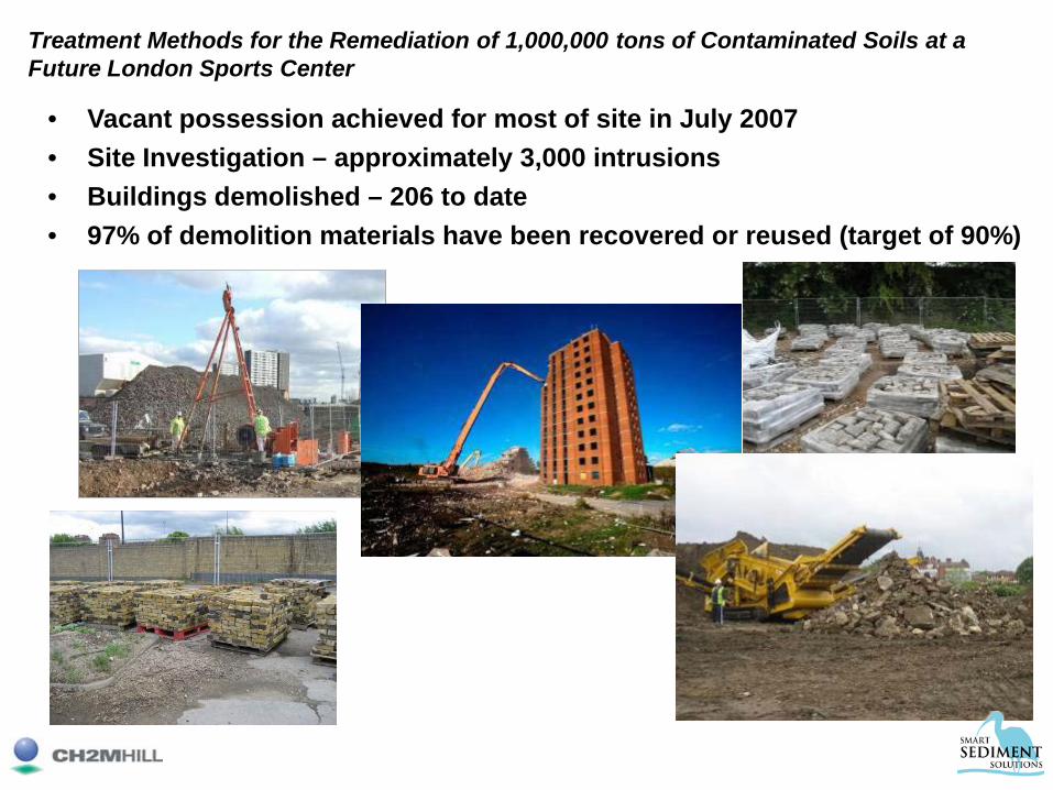
• Vacant possession achieved for most of site in July 2007• Site Investigation – approximately 3,000 intrusions• Buildings demolished – 206 to date• 97% of demolition materials have been recovered or reused (target of 90%)
Treatment Methods for the Remediation of 1,000,000 tons of Contaminated Soils at a Future London Sports Center

Treatment Methods for the Remediation of 1,000,000 tons of Contaminated Soils at a Future London Sports Center
Remediation - Main Contaminants of concern• Heavy Metals (e.g. Lead, Arsenic, Chromium)• TPH Organics (e.g. Fuel Oil)• Ammonia• PAH Organics (e.g. Coal Tar, Bitumens)• Chlorinated hydrocarbons (PCE, DCE,TCE and VC)• Very low radioactive waste• Asbestos• Combinations of the above.

Treatment Methods for the Remediation of 1,000,000 tons of Contaminated Soils at a Future London Sports Center
• Excavation hydrocarbon Hot Spot• Primary screening• Treatment

Treatment Methods for the Remediation of 1,000,000 tons of Contaminated Soils at a Future London Sports Center
Aerial View of 5
Soil Washing Plants
Operating at the site
Soil Treatment Methods

Treatment Methods for the Remediation of 1,000,000 tons of Contaminated Soils at a Future London Sports Center
Materials Balance – Enabling Works
Sand
Gravel
Contaminated Soil
Soil washed sand Soil washed gravel
Blended ProductSWS+SWG+PLUG
Filter cake waste Light waste
Soil Treatment Methods

Treatment Methods for the Remediation of 1,000,000 tons of Contaminated Soils at a Future London Sports Center
Aerial view of site prior to start of project
Alternative Treatment Methods
Stabilisation Plant
Bio-remediation Cells
Soil Treatment Methods

Treatment Methods for the Remediation of 1,000,000 tons of Contaminated Soils at a Future London Sports Center
Sustainable Soil Reuse
• Filter Cake T&D’ed offsite to landfill - 91,000m3 at equivalent moisture
• Geotechnical unsuitable material T&D’ed offsite to landfill - 80,000m3
• TOTAL Reused to date 1.8 Million m3
(89% of excavated material)

1. Dates of operation: First plant was mobilized to site 18th July 2007. Full production with 3 plants at the soil hospital as from February 2008. Expecting to remain on site until June 2010 at least.
2. A total of 5 soils washing plants have been provided to the site. DEC has provided 3 soil washing plants.
3. Production capacity of the 3 washing plants combined is up to 14,000 tons/week. Maximum 100t/hr per plant average 70t/hr.
4. Operational schedule has been 12hrs/day - 6 or 7 days per week. Operations have only stopped for exceptionally cold weather.
5. Total soil washed to date is just over 1,000,000 tons
6. Cost of soil washing varies between $60-70/ton, including disposal of filter cakes (which constitutes the bulk of the cost)
7. Cost for debris scalping ≈ $3/ton.
8. All oversized masonry and concrete material is crushed and is usually acceptable for direct reuse on site without further treatment.
9. Enriched fines/filter cake 91,000m3 was not stabilized but simply dewatered and T&D’ed to a secured landfill.
10. Chemically stabilize 62,300t of non-washable (high fine content) soils for beneficial reuse on site.
11. Bio-remediated 53,386t of TPH contaminated soil.
Summary of Accomplishments
Treatment Methods for the Remediation of 1,000,000 tons of Contaminated Soils at a Future London Sports Center

• Prepare Work Plans• Site Mob/ Treatment Area
Construction• Clearing and Grubbing• Debris Removal• Dredging to Plan Grades• Onshore Sediment Handling and
Dewatering• Water Control, Treatment and Return
to Borrow Pit• Env. Monitoring (sediment, water and
air)• Post Removal Bathymetric Surveys• Transportation and Disposal of
Sediment• Capping• Treatment Area Demo/ Clean-up and
Demobilization• Final Reports
Project ScopeTampa Waters Ave. – temporary parking lot Geotube dewatering of 14,820 CY sediments

Dredging & Dewatering AreasDecon
Pad
WaterTreatment
System
Admin Trailers
Borrow Pit
Shelf Area
Hydraulic Dredgeand Pipeline
WeepWaterSump
DischargePipeline
And Diffuser
290’
PrimarySilt
Curtain
A-2
A-3
A-4
1200 60
355’
ContainmentFacility
Interior Sand Berms2’ x 2.5’ x 250’
Exterior Sand Berms
Light Poles andOverhead 220V lines
NSand Stockpile Area
Distribution Bargeand
Travel Cable
SecondarySilt
Curtain
SandFeedBox
Tampa Waters Ave. – temporary parking lot Geotube dewatering of 14,820 CY sediments
460’
460’

8” dia. Horizontal Auger Head Dredge in Production
Tampa Waters Ave. – temporary parking lot Geotube dewatering of 14,820 CY sediments
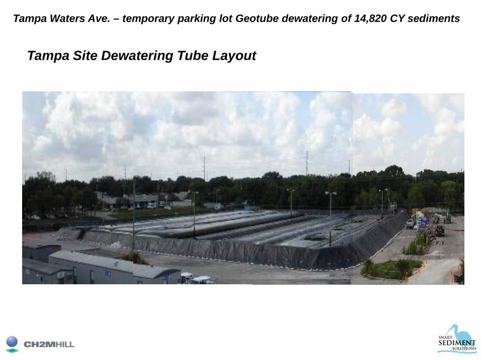
Tampa Site Dewatering Tube Layout
Tampa Waters Ave. – temporary parking lot Geotube dewatering of 14,820 CY sediments
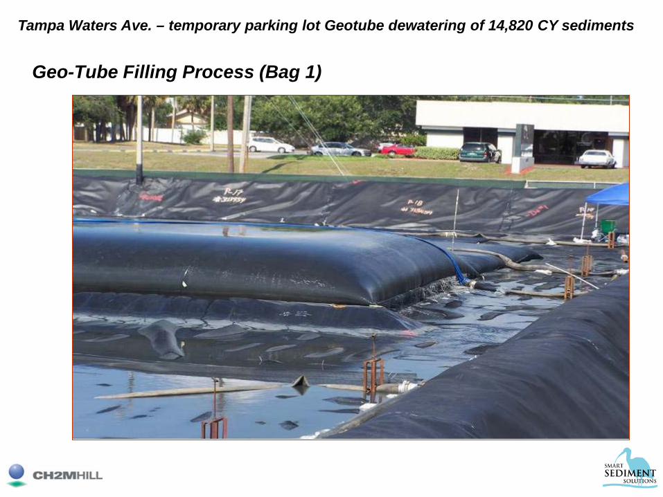
Geo-Tube Filling Process (Bag 1)
Tampa Waters Ave. – temporary parking lot Geotube dewatering of 14,820 CY sediments
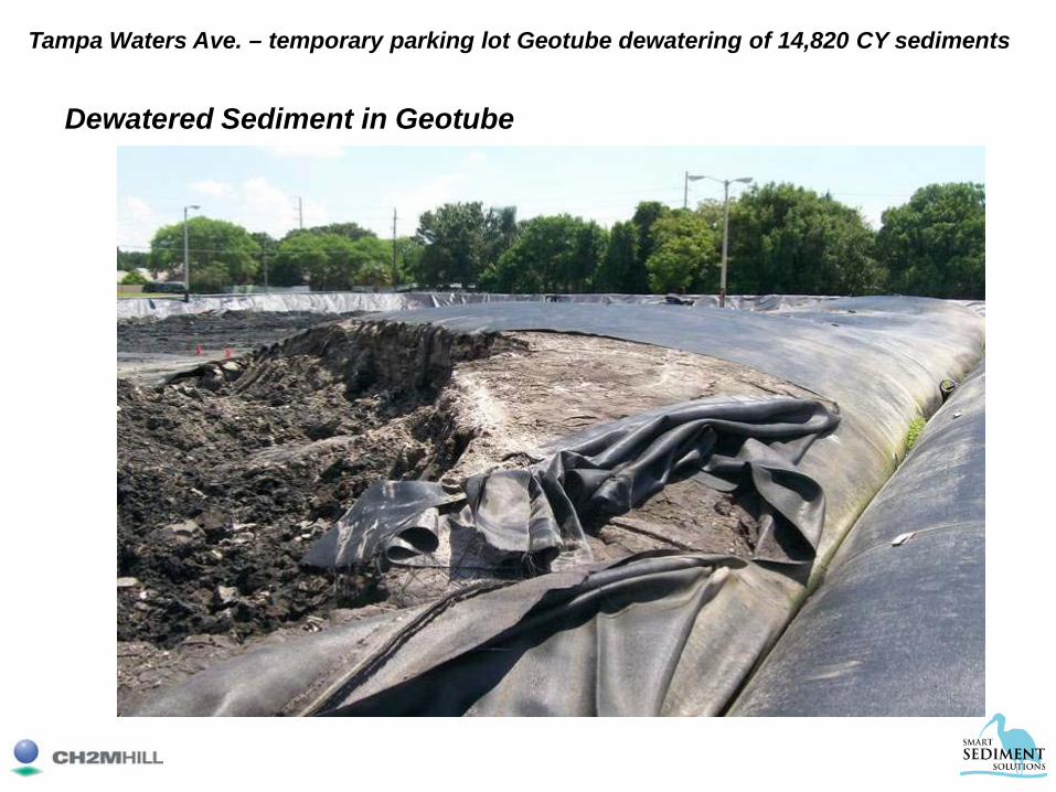
Dewatered Sediment in Geotube
Tampa Waters Ave. – temporary parking lot Geotube dewatering of 14,820 CY sediments

Sediment Load-Out
Tampa Waters Ave. – temporary parking lot Geotube dewatering of 14,820 CY sediments

Lessons Learned• Design methods
• Expect the unexpected!
Undetected Debris Object
Tampa Waters Ave. – temporary parking lot Geotube dewatering of 14,820 CY sediments

Tampa Project Statistics
• Amount of Sediment Removed: – 14,820 CY
• Average Percent Solids – In-Situ: 9% to 28%– After dewatering: 55%
• Polymer Dosage:– Lab Results: 8 pounds per dry ton– Actual: 6.4 pounds per dry ton
• Sediment transported for disposal: – 14,600 tons vs. 26,500 from design estimate
• Project on Schedule with no reportable injuries– Project start April 25, 2007– Demobilization completed October 12, 2007
Dredge SlurryDredge Slurry w/ PolymerTube Effluent
Tampa Waters Ave. – temporary parking lot Geotube dewatering of 14,820 CY sediments

22

Project Overview
• Mechanical dredging using environmental bucket:– 167,000 cubic yards of
PCB and PAH-contaminated sediments 2,000 linear feet of river channel
• Transport dredged material to Confined Disposal Facility
• Placement of sand cover to address residual contamination that cannot be dredged.
23
Kinnickinnic (KK) River Dredging and Disposal Project
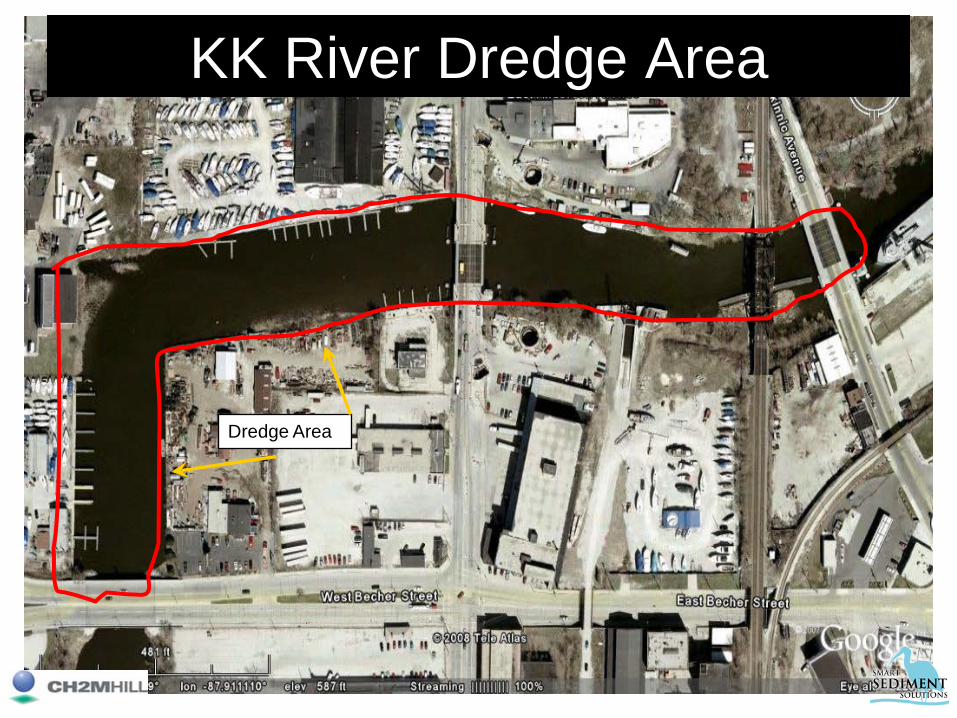
KK River Dredge Area
Dredge Area
24

25
Dredged material transported by barge to cell
Confined Disposal Facility
Dredge Project Area
25

Environmental Bucket & Positioning Software
26
Kinnickinnic (KK) River Dredging and Disposal Project

Air Curtain for Turbidity Control
• Installed at downstream end of project• Operational between mid-June and end
of sand placement operations• Silt curtains were used for first 2 weeks
of dredging until air curtain installation was completed, after which silt curtains were removed
27
Kinnickinnic (KK) River Dredging and Disposal Project

Sediment
KK River Dredge Area
Air Curtain
Final Grade
Induced Current
Kinnickinnic (KK) River Dredging and Disposal Project
• Installed at downstream end of project
Air Curtain for Turbidity Control
• What is an air curtain?– Perforated pipe with custom nozzles laid across
river channel (typically trenched in a few feet into the existing sediment)
– Compressed air is continuously blown through the pipe creating a wall of bubbles that rises to the water surface
– Wall of bubbles causes some suspended solids in the water column to fall out
Air Curtain for Turbidity Control
29
Kinnickinnic (KK) River Dredging and Disposal Project
• Advantages of air curtains (over floating curtains)– Infrastructure does not move with high currents;
once it is set up and operating, maintenance is minimal.
– No disruption to boat traffic; vessels can cross curtain unimpeded.
– Once initial monitoring establishes effectiveness of the air curtain, it is obvious when it is operational.
• Disadvantages of air curtains– Requires constant power source; compressor can
be noisy.– Effectiveness limited during extremely high flow
events.
Air Curtain for Turbidity Control
30
Kinnickinnic (KK) River Dredging and Disposal Project

Air Curtain Downstream of Dredge Area
31

Performance of Air Curtain
• Air curtain operated continuously throughout project & required no maintenance.
• Average drop in turbidity reading from 30 feet upstream of air curtain (KK Avenue Bridge) to 1,000 feet downstream of curtain was 25 NTUs.
• Survey indicated buildup of several feet of sediment on both sides of the air curtain (removed at end of project).
32
Kinnickinnic (KK) River Dredging and Disposal Project

Problem: How do you move 167,000 cubic yards of material into cell w/soft bottom?
~600’
~1,000’
33
Kinnickinnic (KK) River Dredging and Disposal Project
• Initial assumption was that offloaded material from barges would flow in CDF
• Existing material in bottom of CDF was extremely soft, too soft even for LGP equipment to distribute the off-loaded material
• Utilized logging industry technology with a dragline bucket to distribute material evenly throughout the CDF
Kinnickinnic (KK) River Dredging and Disposal Project
Ramsey Dragline System w/Sauerman Bucket at CDF

Dragline System w/Sauerman Bucket at CDF
35
Kinnickinnic (KK) River Dredging and Disposal Project

Ramsey Dragline System w/Sauerman Bucket at CDF
36

Sand Broadcast Spreader
37
Kinnickinnic (KK) River Dredging and Disposal Project

38
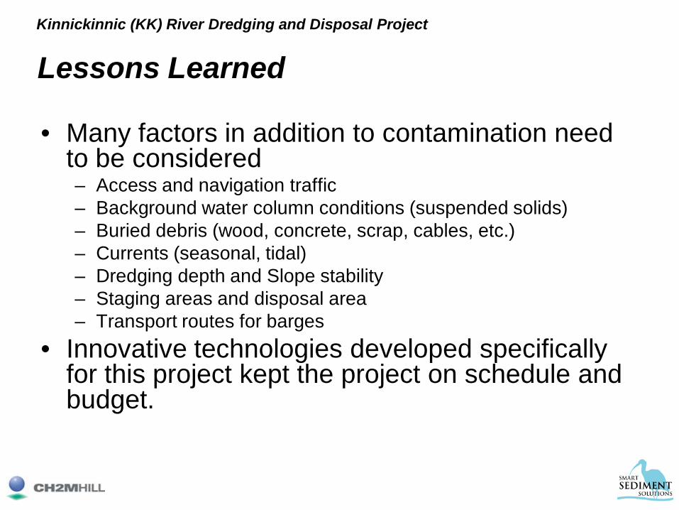
Lessons Learned
• Many factors in addition to contamination need to be considered– Access and navigation traffic– Background water column conditions (suspended solids)– Buried debris (wood, concrete, scrap, cables, etc.) – Currents (seasonal, tidal) – Dredging depth and Slope stability – Staging areas and disposal area – Transport routes for barges
• Innovative technologies developed specifically for this project kept the project on schedule and budget.
Kinnickinnic (KK) River Dredging and Disposal Project

CH2M HILL / Brennan Team
Lower Fox River Operable Unit 1
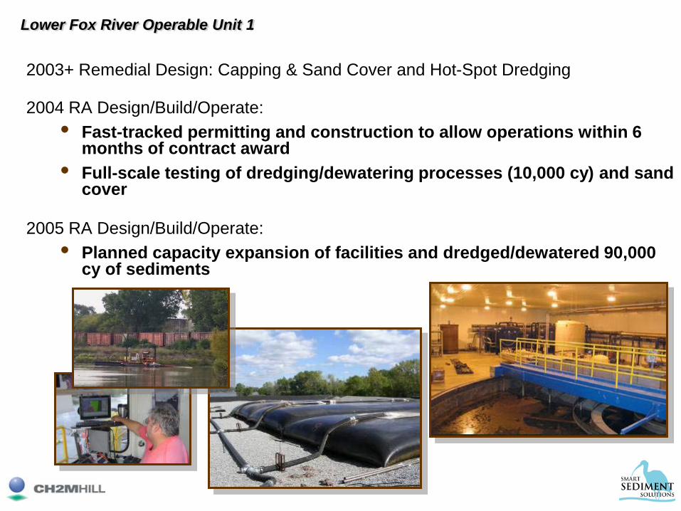
2003+ Remedial Design: Capping & Sand Cover and Hot-Spot Dredging
2004 RA Design/Build/Operate: • Fast-tracked permitting and construction to allow operations within 6
months of contract award• Full-scale testing of dredging/dewatering processes (10,000 cy) and sand
cover
2005 RA Design/Build/Operate: • Planned capacity expansion of facilities and dredged/dewatered 90,000
cy of sediments
Lower Fox River Operable Unit 1
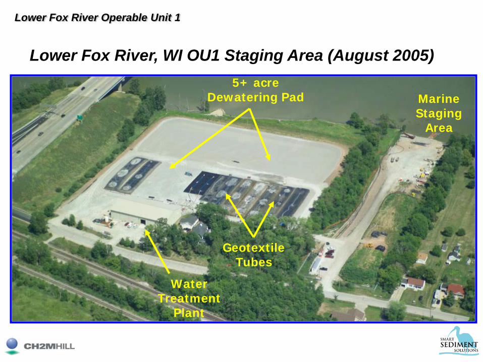
Water Treatment
Plant
Geotextile Tubes
5+ acre Dewatering Pad Marine
Staging Area
Lower Fox River, WI OU1 Staging Area (August 2005)
Lower Fox River Operable Unit 1
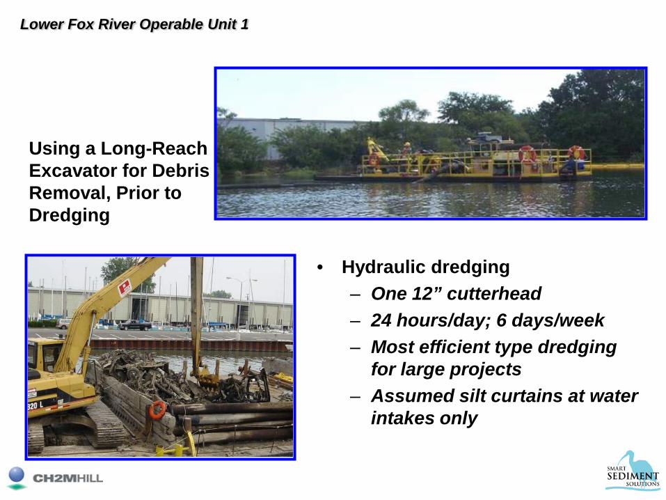
Using a Long-Reach Excavator for Debris Removal, Prior to Dredging
• Hydraulic dredging– One 12” cutterhead– 24 hours/day; 6 days/week– Most efficient type dredging
for large projects– Assumed silt curtains at water
intakes only
Lower Fox River Operable Unit 1

Dewatering Plan• Geotextile tube dewatering
– 80- and 100-foot-circumference tubes– Stacking up to 3 tubes high– 45-60 day dewatering time– Allows high project % up-time (high 80s to low 90s)
• Combine coarse-grained and fine-grained sediments to aid dewatering– One dredge in areas with coarse-grained sediment – One dredge in areas with fine-grained, highly organic
content sediment• Chemical Feed
– Medium molecular weight, low cationic charge polymer
Lower Fox River Operable Unit 1

Geotube Dewatering • Isolate >50 ppm sediment • Feed geotubes at an average
rate of 8,000 insitu CY per week
• Sediment will be stored and dewatered in geotubes on the pad
• Haul out at a rate of 1,100 tons/day
• Haul out to continue through December
Lower Fox River Operable Unit 1

LFR Geotextile Tubes on Dewatering Pad
TSCA Sediment
Stacking 80-foot Circumference Tubes
Non-TSCA Sediment
Lower Fox River Operable Unit 1

• Water Treatment– Heavy fraction remains in dewatering pad– Dissolved air flotation / filtration– Granular activated carbon– Outfall diffuser– Lower capital cost– Lower O&M cost– Simpler operation
Lower Fox River Operable Unit 1
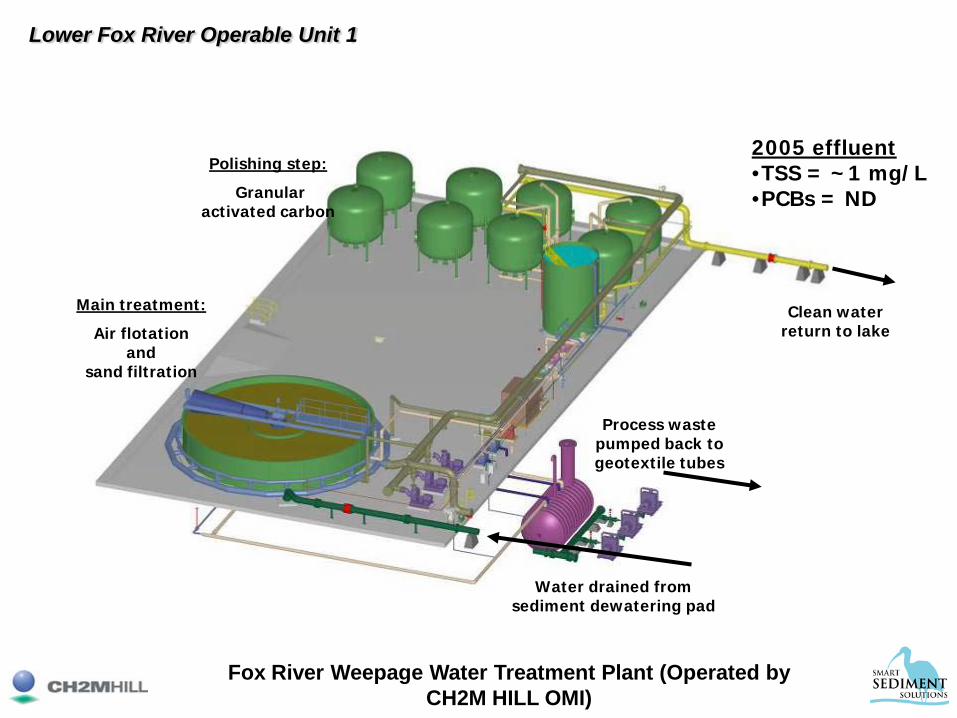
Fox River Weepage Water Treatment Plant (Operated by CH2M HILL OMI)
Main treatment:
Air flotationand
sand filtration
Polishing step:
Granular activated carbon
Process waste pumped back to geotextile tubes
Water drained from sediment dewatering pad
Clean water return to lake
2005 effluent•TSS = ~1 mg/L•PCBs = ND
Lower Fox River Operable Unit 1

Transportation and Disposal Approach Features Hauling in lined trucks
– Onyx Hickory Meadows Landfill (Chilton, WI)– Permitted to 5 million cy– Room for expansion– In-State option for TSCA waste
Lower Fox River Operable Unit 1

• 2.5-yard clamshell bucket
• Haul non-TSCA material to Onyx Landfill in Chilton, WI
Lower Fox River Operable Unit 1
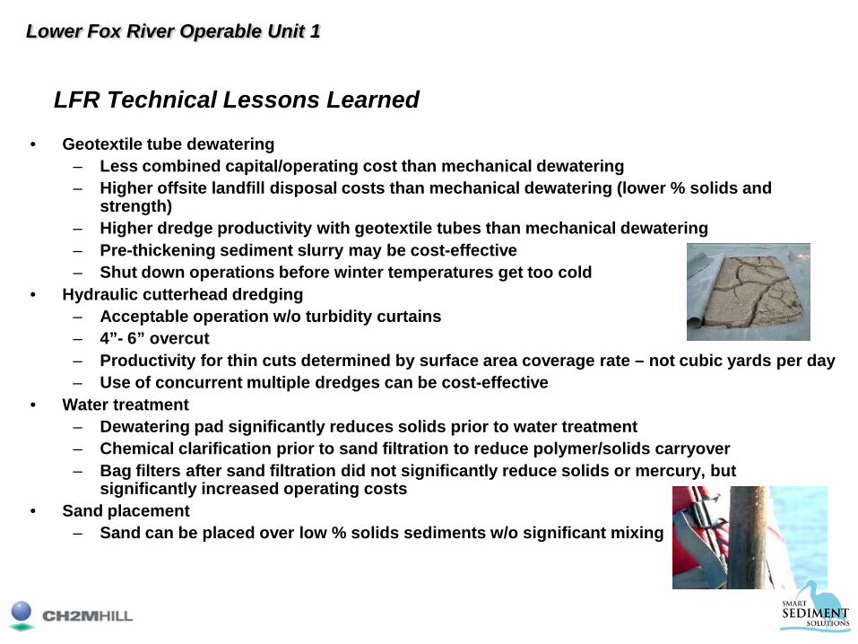
LFR Technical Lessons Learned
• Geotextile tube dewatering– Less combined capital/operating cost than mechanical dewatering– Higher offsite landfill disposal costs than mechanical dewatering (lower % solids and
strength)– Higher dredge productivity with geotextile tubes than mechanical dewatering– Pre-thickening sediment slurry may be cost-effective– Shut down operations before winter temperatures get too cold
• Hydraulic cutterhead dredging– Acceptable operation w/o turbidity curtains– 4”- 6” overcut– Productivity for thin cuts determined by surface area coverage rate – not cubic yards per day– Use of concurrent multiple dredges can be cost-effective
• Water treatment– Dewatering pad significantly reduces solids prior to water treatment– Chemical clarification prior to sand filtration to reduce polymer/solids carryover– Bag filters after sand filtration did not significantly reduce solids or mercury, but
significantly increased operating costs• Sand placement
– Sand can be placed over low % solids sediments w/o significant mixing
Lower Fox River Operable Unit 1

3 - Do's1. Plan ahead - solicit and utilize unbiased, peer-review evaluations of the
proposed project from recognize experts in the field;2. Three most important elements of a successful project - details, Details,
DETAILS;3. Be flexible – try to expect the unexpected – Murphy lurks everywhere;
3 - Don'ts1. Permitting and legal requirements – don’t trivialize agency submittals, review
lead times and public opinion;2. Don’t underestimate project contingencies (ie., bad weather, more/less
material than expected, differing feed characteristics, varying contaminant concentrations, etc.);
3. Don’t trivialize initial feedstock preparation in bulk soil/sediment pretreatment steps such as debris separation (snag boats), coarse screening, crushing/shredding, and physical/chemical characterization of oversized material for potential non-hazardous wastes disposal alternatives;
Summary & Take-aways

From 1948 to 1949, a project known as MX981 took place on Muroc Field (later renamed Edwards Air Force Base) for the purpose of testing the human tolerance for g-forces during rapid deceleration. The Law's namesake was Capt. Ed Murphy, a development engineer from Wright Field Aircraft Lab. Frustration with a strap transducer which was malfunctioning due to an error in wiring the strain gage bridges caused him to remark - "If there is any way to do it wrong, he will!" -referring to the technician who had wired the bridges at the Lab. The PM assigned Murphy's Law to the statement and all the associated variations. – ref. Wikipedia
Although often equated with Sod's law (chiefly British),
“Everything that can possibly go wrong will go wrong” - Murphy's Extended Law
If a series of events can go wrong, they will do so in the worst possible sequence.
"If there's more than one way to do a job, and one of those ways will result in disaster, then somebody will do it that way."
O'Toole's Commentary on Murphy's Law: “Murphy was an optimist”!
Summary & Take-aways
Capt. Ed Murphy
Summary & Take-aways