Remedial Design Work Plan August 2003 - US EPA · Remedial Design Work Plan ... Remedial Design...
84
W ORK P LAN Remedial Design Work Plan Hudson River PCBs Superfund Site General Electric Company Albany, New York August 2003
-
Upload
phamkhuong -
Category
Documents
-
view
220 -
download
0
Transcript of Remedial Design Work Plan August 2003 - US EPA · Remedial Design Work Plan ... Remedial Design...
W O R K P L A N
Remedial Design Work Plan Hudson River PCBs Superfund Site
General Electric CompanyAlbany, New York
August 2003

BLASLAND, BOUCK & LEE, INC. e n g i n e e r s & s c i e n t i s t s i
Table of Contents
Section 1. Introduction ............................................................................................................... 1-1
1.1 Project Setting..................................................................................................................1-2 1.2 Remedial Action Summary ..............................................................................................1-2 1.3 Remedial Design Objectives............................................................................................1-4 1.4 Work Plan Organization...................................................................................................1-5 1.5 Overview of Remedial Design Process ...........................................................................1-7
Section 2. Design Support Activities ........................................................................................ 2-1
2.1 Pre-Design Characterization Activities ............................................................................2-1 2.1.1 Description of Pre-Design Characterization Activities ........................................2-2 2.1.2 Deliverables ........................................................................................................2-4
2.2 RD Engineering Data Collection and Analysis ................................................................2-5 2.2.1 Objectives ...........................................................................................................2-5 2.2.2 Description..........................................................................................................2-6 2.2.3 Deliverables ........................................................................................................2-8
2.3 Base-Mapping Activities ..................................................................................................2-8 2.4 Dredge Area Delineation .................................................................................................2-9 2.5 Baseline Monitoring Activities ........................................................................................2-13 2.6 Development of Performance Standards ......................................................................2-13 2.7 Selection of Sediment Removal Areas for Phase 1 Dredging.......................................2-14 2.8 Sediment Processing/Transfer Facility Siting Activities.................................................2-15 2.9 Habitat Delineation and Assessment.............................................................................2-17 2.10 Cultural and Archaeological Resources Assessment....................................................2-18 2.11 Treatability Studies ........................................................................................................2-19 2.12 River Hydraulic Analyses...............................................................................................2-21
Section 3. Engineering Design Process ................................................................................... 3-1
3.1 Project Phasing and Design Components.......................................................................3-1 3.1.1 Dredging .............................................................................................................3-4
3.1.1.1 Design Process ...................................................................................3-4 3.1.2 Dredged Material Transport................................................................................3-6
3.1.2.1 Barge Transport (Mechanical Removal) .............................................3-7 3.1.2.2 Pipeline Transport (Hydraulic and Mechanical Removal)...................3-8 3.1.2.3 Design Process ...................................................................................3-9
3.1.3 Resuspension Control Systems........................................................................3-10 3.1.3.1 Design Process .................................................................................3-11
3.1.4 Material Handling, Dewatering, and Water Treatment .....................................3-11 3.1.4.1 Design Process .................................................................................3-13
3.1.5 Final Transportation and Disposal ....................................................................3-14 3.1.5.1 Design Process .................................................................................3-15
3.1.6 Capping Contingency for Residual Sediments .................................................3-16 3.1.7 Habitat Replacement and Reconstruction ........................................................3-17
3.1.7.1 Goals of the Habitat Replacement and Reconstruction Program.....3-18 3.1.7.2 Design Process .................................................................................3-18
3.2 Value Engineering Study ...............................................................................................3-19

BLASLAND, BOUCK & LEE, INC. e n g i n e e r s & s c i e n t i s t s ii
Section 4. Remedial Design Deliverables ................................................................................. 4-1
4.1 Monthly Reports...............................................................................................................4-1 4.2 Design Support Deliverables ...........................................................................................4-1
4.2.1 Work Plans..........................................................................................................4-2 4.2.2 Reports ...............................................................................................................4-3
4.3 Engineering Design Deliverables.....................................................................................4-6 4.3.1 Preliminary Design Report..................................................................................4-7 4.3.2 Intermediate Design Reports ..............................................................................4-7 4.3.3 Final Design Reports ..........................................................................................4-9
4.4 Final Design Support Deliverables ................................................................................4-11
Section 5. Remedial Design Schedule ...................................................................................... 5-1
Section 6. References................................................................................................................. 6-1
Tables 1 Work Plan Organization (placed in text)
2 Engineering Design Document Summary
3 Design Support Sampling and Analyses Summary Table
4 Remedial Design Schedule
Figure 1 Upper Hudson River
Appendices (Separately Bound) A Habitat Delineation and Assessment Work Plan
B Cultural and Archaeological Resources Assessment Work Plan
C Baseline Monitoring Program Scoping Document

BLASLAND, BOUCK & LEE, INC. e n g i n e e r s & s c i e n t i s t s 1-1
1. Introduction This document has been prepared on behalf of the General Electric Company (GE) and presents a Remedial
Design Work Plan (RD Work Plan) for the design of the remedy selected by the United States Environmental
Protection Agency (USEPA) to address polychlorinated biphenyls (PCBs) in sediments of the Upper Hudson
River, located in New York State. The objective of this RD Work Plan is to provide the framework for
developing design documents (including plans and specifications) for the USEPA-selected remedy. This
framework will cover the RD tasks to be performed by GE. It should be noted that GE will perform all activities
needed to complete the engineering design, except for those being performed by the USEPA, which include the
following:
• Identifying and evaluating the on-shore sites needed for the sediment processing/transfer facilities and
completing associated cultural and archaeological assessment and habitat delineation and assessment
activities;
• Developing engineering and quality of life performance standards (engineering performance standards will
be established for resuspension during dredging, PCB residuals after dredging, and dredging production
rates; quality of life performance standards will include PCB air emissions and community impacts [e.g.,
noise, light, and odor]);
• Coordinating the peer reviews of the engineering performance standards and the report which evaluates
Phase 1 dredging; and
• Developing and implementing the Community Involvement Plan.
GE will provide input and support, as appropriate, to these USEPA-led activities.
The activities described in this RD Work Plan will be conducted under an Administrative Order on Consent for
RD (hereafter referred to as the “RD AOC”). Pre-design sediment sampling activities are being conducted
under the AOC for the sediment sampling program (hereafter referred to as the “Sediment Sampling AOC”)
executed by the USEPA on July 23, 2002, effective July 26, 2002 (Index No. CERCLA-02-2002-2023)
(USEPA, 2002a).
This RD Work Plan was developed consistent with applicable USEPA guidance documents, including:
• Guidance for Scoping the Remedial Design (USEPA, 1995a);

BLASLAND, BOUCK & LEE, INC. e n g i n e e r s & s c i e n t i s t s 1-2
• Remedial Design/Remedial Action Handbook (USEPA, 1995b); and
• Guidance on USEPA Oversight of Remedial Designs and Remedial Actions Performed by Potentially
Responsible Parties (USEPA, 1990a).
1.1 Project Setting
The Hudson River is located in eastern New York State and flows approximately 300 miles in a generally
southerly direction from its source, Lake Tear-of-the-Clouds in the Adirondack Mountains, to the Battery,
located in New York City at the tip of Manhattan Island. The USEPA issued a Superfund Record of Decision
(ROD) on February 1, 2002, calling for, among other things, the removal and disposal of approximately 2.65
million cubic yards of PCB-contaminated sediments from the Upper Hudson River (USEPA, 2002b). The
USEPA divided the Upper Hudson River into three sections (River Section 1, River Section 2, and River
Section 3) (hereafter referred to as the “Upper Hudson River”) for the sediment remediation activities outlined
in the USEPA’s 2002 ROD. The location of each section is described below and presented on Figure 1:
• River Section 1: Former location of Fort Edward Dam to Thompson Island Dam (approximately 6.3
miles);
• River Section 2: Thompson Island Dam to Northumberland Dam (approximately 5.1 miles); and
• River Section 3: Northumberland Dam to the Federal Dam at Troy (approximately 29.5 miles).
1.2 Remedial Action Summary
This section summarizes the remedy selected in USEPA’s ROD (USEPA, 2002b). As stated in the USEPA’s
2002 ROD (pages ii-iv and 94-96), the major components of the USEPA-selected remedy for the PCB-impacted
sediments in the Upper Hudson River include the following:
• Removal of sediments based primarily on a mass per unit area (MPA) of 3 grams per meter squared (g/m2)
Tri+ PCBs or greater (approximately 1.56 million cubic yards of sediments) from River Section 1;
• Removal of sediments based primarily on an MPA of 10 g/m2 Tri+ PCBs or greater (approximately 0.58
million cubic yards of sediments) from River Section 2;

BLASLAND, BOUCK & LEE, INC. e n g i n e e r s & s c i e n t i s t s 1-3
• Removal of selected sediments with high concentrations of PCBs and high erosional potential (NYSDEC
Hot Spots 36, 37, and the southern portion of 39) (approximately 0.51 million cubic yards) from River
Section 3;
• Dredging of the navigation channel, as necessary, to implement the remedy and to avoid hindering canal
traffic during implementation. Approximately 341,000 cubic yards of sediments will be removed from the
navigation channel (included in volume estimates in the first three components, above);
• Removal of all PCB-contaminated sediments within areas targeted for remediation, with an anticipated
residual of approximately 1 milligram per kilogram (mg/kg) Tri+ PCBs (prior to backfilling);
• Performance standards for air quality and noise are included in this ROD consistent with state and federal
law [the noise standard as presented in the ROD was adopted preliminarily – public input will be invited
prior to finalization];
• Other performance standards (including but not necessarily limited to resuspension rates during dredging,
production rates during dredging, and residuals after dredging) will be developed during the design with
input from the public and in consultation with the state and federal natural resource trustees. These
performance standards will be enforceable, and based on objective environmental and scientific criteria. The
standards will promote accountability and ensure that the cleanup meets the human health and
environmental protection objectives of the ROD;
• Independent external peer review of dredging resuspension, PCB residuals, and production rate performance
standards and the attendant monitoring program, as well as the report prepared at the end of the first phase
of dredging that will evaluate dredging with respect to these performance standards;
• Performance of the dredging in two phases whereby remedial dredging will occur at a reduced rate during
the first year of dredging. This will allow comparison of operations with pre-established performance
standards and evaluation of necessary adjustments to dredging operations in the succeeding phase or to the
standards. Beginning in Phase 1 and continuing throughout the life of the project, the USEPA will conduct
an extensive monitoring program. The data that the USEPA gathers, as well as the Agency’s ongoing
evaluation of the work with respect to the performance standards, will be made available to the public in a
timely manner and will be used to evaluate the project to determine whether it is achieving its human health
and environmental protection objectives;
• Backfill of dredged areas with approximately one foot of clean material to isolate residual PCB
contamination and to expedite habitat recovery, where appropriate;
• Use of rail and/or barge for transportation of clean backfill materials within the Upper Hudson River area;
• Monitored Natural Attenuation (MNA) of PCB contamination that remains in the river after dredging;

BLASLAND, BOUCK & LEE, INC. e n g i n e e r s & s c i e n t i s t s 1-4
• Use of environmental dredging techniques to minimize and control resuspension of sediments during
dredging;
• Transport of dredged sediments via barge or pipeline to sediment processing/transfer facilities for
dewatering and, as needed, stabilization;
• Rail and/or barge transport of dewatered, stabilized sediments to an appropriate licensed off-site landfill(s)
for disposal. If a beneficial use of some portion of the dredged material is arranged, then an appropriate
transportation method will be determined (rail, truck, or barge);
• Monitoring of fish, water and sediment to determine when Remediation Goals are reached, and also
monitoring the restoration of aquatic vegetation; and
• Implementation (or modification) of appropriate institutional controls such as fish consumption advisories
and fishing restrictions by the responsible authorities, until relevant Remediation Goals are met.
1.3 Remedial Design Objectives
The primary objective of the RD for the Upper Hudson River is to develop plans and specifications for
implementing the USEPA-selected remedy, consistent with the USEPA’s 2002 ROD, and, in the course of doing
so, to ensure that the remedy is implemented in a safe and efficient manner. Specific activities to accomplish
this primary RD objective are to:
• Collect and analyze data (and other information) necessary to support the RD for the Upper Hudson River;
• Develop engineering and design specifications to support USEPA efforts in identifying and evaluating land-
based sites needed to implement the project, including the sediment processing/transfer facilities;
• Design the facilities for the handling and processing to prepare removed sediment for transport and disposal,
and treatment of separated water prior to discharge back into the river;
• Design a dredging program with a target project duration of a total of 6 years (1 year for Phase 1 and 5 years
for Phase 2), consistent with the performance standards that will be established during design;
• Develop engineering and design information to support the identification and selection of the sediment areas
to be removed during the Phase 1 dredging program;
• Develop design documents for the Phase 1 and Phase 2 dredging programs with the goal of achieving the
performance standards established by the USEPA;
• Develop RD deliverables to allow timely execution of the Phase 1 and Phase 2 dredging programs; and

BLASLAND, BOUCK & LEE, INC. e n g i n e e r s & s c i e n t i s t s 1-5
• Develop an effective monitoring program, starting with implementation of a baseline monitoring program,
to allow an assessment of the results of remedy implementation (including the monitored natural attenuation
component of the remedy) relative to the performance standards and remedial goals established by the
USEPA.
1.4 Work Plan Organization
This RD Work Plan is organized into the sections shown in Table 1 below.
Table 1 – Work Plan Organization
Section Description
1 – Introduction Presents background information and project objectives.
2 – Design Support Activities Describes the activities to support the design, and their
interrelationships and dependencies.
3 – Engineering Design Process Presents the engineering design process, including a description of the
various design components, deliverables, and their interdependencies.
4 – Remedial Design Deliverables Describes the various deliverables to be produced during the RD
process.
5 – Remedial Design Schedule Describes project schedule components for the RD.
6 – References Presents references used to prepare this RD Work Plan.
Tables Provides tables that are referenced in this RD Work Plan.
Figures Provides figures that are referenced in this RD Work Plan.
Appendices Provides work plans that are attached to this RD Work Plan.
This RD Work Plan is supplemented by the following documents, which have been previously prepared by GE
and its consultants and submitted to, and/or approved by, the USEPA under the Sediment Sampling AOC:
• Sediment Sampling and Analysis Program – Field Sampling Plan (SSAP–FSP) (Quantitative Environmental
Associates, Inc. [QEA], 2002a) describes the pre-design sediment sampling and analysis program (SSAP).
This plan was approved by the USEPA as part of the Sediment Sampling AOC and is currently being
implemented.

BLASLAND, BOUCK & LEE, INC. e n g i n e e r s & s c i e n t i s t s 1-6
• Quality Assurance Project Plan (QAPP) (QEA and Environmental Standards, Inc. [ESI], 2002) presents the
quality assurance/quality control (QA/QC) protocols to be followed during sediment sampling and
laboratory analytical efforts. This QAPP was submitted to the USEPA in connection with the Sediment
Sampling AOC and approved by the USEPA on October 1, 2002.
• Sub-Bottom Profiling Test Work Plan (SBPT Work Plan) (QEA, 2002b) describes the sub-bottom profiling
activities to be conducted to assess capabilities of remote sensing technologies in delineating Hudson River
sub-bottom conditions. This Work Plan has been submitted to the USEPA for the work being performed
under the Sediment Sampling AOC. Use of these techniques may also provide utility from an engineering
perspective and, if appropriate for that purpose, will be specified in a Supplemental Engineering Data
Collection Work Plan (described in Sections 2.2.3 and 4.2.1).
In addition to the aforementioned documents, the following work plans are provided as appendices to this RD
Work Plan:
• Habitat Delineation and Assessment Work Plan (HDA Work Plan) (Blasland, Bouck & Lee, Inc. [BBL],
2003a) (Appendix A) presents habitat delineation and assessment tasks and associated methodologies to
document existing conditions of Upper Hudson River ecological features.
• Cultural and Archaeological Resources Assessment Work Plan (CARA Work Plan) (URS Corporation
[URS], 2003) (Appendix B) presents the details of the procedures and protocols to be followed for the
cultural and archaeological resources assessment.
• Baseline Monitoring Program Scoping Document (QEA, 2003) (Appendix C) outlines the baseline water
column and fish monitoring activities to be conducted prior to dredging activities. (Under the RD AOC, a
more detailed Baseline Monitoring Quality Assurance Project Plan [Baseline Monitoring QAPP] will be
developed to specify the sampling and analytical procedures for the baseline [i.e., pre-dredging] water
column and fish monitoring programs. This QAPP will be consistent with the Baseline Monitoring
Program Scoping Document in Appendix C.)
Further, a Revised Community Health and Safety Plan (Revised CHASP) (BBL, 2003b), which represents a
revision and update to the CHASP (QEA, 2002c) previously approved for work under the Sediment Sampling
AOC, is attached to the RD AOC as Appendix 2. This Revised CHASP presents protocols addressing aspects of

BLASLAND, BOUCK & LEE, INC. e n g i n e e r s & s c i e n t i s t s 1-7
the field investigation activities to be performed as part of this RD Work Plan that may affect the health and
safety of the local community, as well as continuing to cover community-related health and safety aspects of
future sampling activities under the Sediment Sampling AOC.
Finally, a Revised Health and Safety Plan (Revised HASP) will be submitted under the RD AOC following its
execution. This Revised HASP will represent a revision of the HASP (QEA, 2002d) which was previously
submitted to the USEPA under the Sediment Sampling AOC and which presents the occupational, safety, and
health program in place during the SSAP activities and a contingency plan in the event of an accident or
emergency during those activities. The Revised HASP will also cover the additional field activities to be
performed under this RD Work Plan.
Additional work plans and reports needed to support the design efforts are described in Sections 2 and 3 of this
RD Work Plan. As necessary, supplemental sampling and/or data collection plans, QAPPs, CHASPs, and
HASPs will be submitted for USEPA approval (except for the HASPs, which would be submitted solely for
USEPA review) for sampling activities conducted pursuant to this RD Work Plan, beyond those specified in the
documents listed above. These plans will address any additional data deemed necessary for fully developing the
engineering design, as well as corresponding protocols, as appropriate. For example, as our current knowledge
of the geotechnical and chemical properties of the sediments is limited, it is anticipated that upon review of the
results from the SSAP investigations, additional data needs may be identified to further develop the engineering
design.
1.5 Overview of Remedial Design Process
Engineering design documents for the RD process are described in Sections 3 and 4 and listed in Table 2.
Following the effective date of the RD AOC, several design support activities will begin simultaneously, as
discussed in Section 2. The Preliminary Design stage, which will describe the conceptual framework, sizing,
and interaction of the components of the overall design, will also begin concurrently with the design support
activities. A Preliminary Design Report will be prepared and submitted to the USEPA at the completion of the
Preliminary Design stage.
The Intermediate Design stage will supplement the Preliminary Design, using data from the design support
activities. Separate Intermediate Design Reports will be prepared and submitted for the Phase 1 and Phase 2

BLASLAND, BOUCK & LEE, INC. e n g i n e e r s & s c i e n t i s t s 1-8
dredging programs, using data from respective sampling activities, and will include plans and specifications (at
the 60% design level of detail). These reports also will utilize information developed or approved by the
USEPA (including approval of the dredge area delineations, selection of the final sediment processing/transfer
facility locations, establishment of final performance standards, etc.), as described further in Section 4.3.2.
Long-lead-time equipment will also be identified at this stage to facilitate timely equipment procurement. A
Value Engineering Study will be conducted near the completion of each of the Phase 1 and Phase 2 Intermediate
Design stages, but before formal submittal of each report to the USEPA.
The Final Design stage will further incorporate additional results from the design support activities and
appropriate design modifications from the Value Engineering Study to optimize the design. The Final Design
stage will finalize the plans and specifications, suitable for procuring contractors to implement the remedy. This
design stage will be completed separately for each dredging phase, as follows:
• The Phase 1 Final Design Report will provide details for the first year of implementation (Phase 1 dredging
program); and
• The Phase 2 Final Design Report will provide implementation details for the rest of the project (Phase 2).
The remainder of this RD Work Plan describes the design activities, interrelationships, schedules, and
deliverables for each element of the RD process for the Hudson River remediation program.
BLASLAND, BOUCK & LEE, INC. e n g i n e e r s & s c i e n t i s t s 2-1
2. Design Support Activities This section describes the design support activities to be conducted during the RD process. These activities
include:
• Pre-design characterization activities;
• RD engineering data collection and analysis;
• Base-mapping activities;
• Dredge area delineation;
• Baseline monitoring activities;
• Development of performance standards;
• Selection of sediment removal areas for Phase 1 dredging;
• Sediment processing/transfer facility siting activities;
• Habitat delineation and assessment;
• Cultural and archaeological resources assessment;
• Treatability studies; and
• River hydraulic analyses.
These design support activities will provide information necessary to develop the engineering design. The
results will be incorporated into the design as they become available. A discussion of the interrelationships of
the various tasks is provided below and in Section 3.
The following sub-sections present the objectives and describe each design support activity.
2.1 Pre-Design Characterization Activities
Pre-design characterization activities are being conducted under the Sediment Sampling AOC. The objective of
these pre-design characterization activities is to obtain site-specific information needed to develop the design. A
separate work plan, the SSAP-FSP (QEA, 2002a), and associated QAPP (QEA and ESI, 2002), HASP (QEA,
2002d), and CHASP (QEA, 2002c), have been developed to specify the protocols for the pre-design
characterization activities. An overview of the pre-design characterization activities and associated deliverables
is presented in the following sub-sections. Please refer to the SSAP-FSP (QEA, 2002a) for additional details.

BLASLAND, BOUCK & LEE, INC. e n g i n e e r s & s c i e n t i s t s 2-2
2.1.1 Description of Pre-Design Characterization Activities The following sub-sections summarize each of the pre-design characterization activities. Geophysical Surveys
Geophysical survey activities will include conducting bathymetric and side-scan sonar surveys in certain
portions of each river section. The bathymetric survey will provide riverbed depth information to augment
existing data for the Upper Hudson River (the SSAP-FSP [QEA, 2002a] summarizes existing riverbed depth
data). The side-scan sonar survey is primarily intended to provide data regarding sediment type, but may also be
used in identifying the presence/absence of cultural and archaeological resources and the location of debris and
obstructions.
In addition, indirect measurements of the sub-bottom profile (i.e., below the sediment) may allow for refined
definition of the boundaries of the areas to be dredged. The side-scan sonar survey activities described above
will provide one means to estimate the horizontal location of the interface between sediment types. Other
geophysical techniques of sub-bottom profiling (such as acoustic and electromagnetic signaling) may provide a
means to delineate the interface between strata and the bottom boundary for dredging. The utility of these
techniques is not assured and depends on various properties of the sediment. These methods will be tested
during the SSAP-FSP activities. If the methods are found to be useful, they may be employed to facilitate
delineation of areas to be dredged, to gather additional data on geotechnical properties, or to better define
subsurface conditions where dredging will occur. An SBPT Work Plan (QEA, 2002b) has been developed
under the Sediment Sampling AOC that identifies the scope of work for sub-bottom profiling testing activities.
Sediment Coring
Sediment coring activities will include collecting sediment core samples along each river section, and
submitting the samples for laboratory analysis of total PCBs, moisture content, bulk density, and Unified Soil
Classification System (USCS) classification. Select samples will also be analyzed for homolog-specific PCBs,
total organic carbon (TOC), 137Cesium (137Cs), Resource Conservation and Recovery Act (RCRA) list metals,
and high-resolution dioxins and furans.
BLASLAND, BOUCK & LEE, INC. e n g i n e e r s & s c i e n t i s t s 2-3
The data collected from the sediment cores, in combination with the geophysical data and the criteria specified
in the USEPA’s 2002 ROD, will provide the information necessary to delineate the areas and depths to be
dredged. In addition, the field observations recorded during sediment core collection will provide additional
data regarding the geotechnical properties of the river sediments and sub-bottom, the location of debris and
obstructions in the riverbed, and additional sediment depth information.
This information is being collected as part of the Sediment Sampling AOC. If additional sediment coring data
are needed beyond the data collected during implementation of the Sediment Sampling AOC, plans for the
collection of such data will be included in the Supplemental Engineering Data Collection Work Plans (described
in Section 2.2.3).
Geotechnical Characterization of Sediments
The objective of the geotechnical characterization of sediments activities is to determine the variability of
geotechnical properties of sediment to be dredged. These activities will include determining the geotechnical
properties (i.e., grain size, Atterberg limits, TOC, specific gravity) of a subset of the river sediment samples
collected during the sediment coring activities. This task will also include compiling geotechnical data based on
the results of the geophysical surveys and field observations recorded during the sediment coring, sediment
probing activities, and visual classification of sediment samples.
Additional sediment geotechnical characterization activities will be conducted as needed as part of the RD
engineering data collection efforts described in Section 2.2.
Sub-Bottom Physical Characterization
The sub-bottom physical characterization will consist of collecting field observations during the sediment coring
activities and manually probing the river bottom; the investigation will also include the results from the sub-
bottom profiling geophysical test efforts described above. This task will be performed in conjunction with the
SSAP-FSP coring program.
As described above under the geophysical survey task, an SBPT Work Plan (QEA, 2002b) has been developed
under the Sediment Sampling AOC that identifies additional geophysical methods to be tested for use in
BLASLAND, BOUCK & LEE, INC. e n g i n e e r s & s c i e n t i s t s 2-4
delineating the interface between the strata and the bottom boundary for dredging. This study may also provide
useful data regarding geotechnical characteristics of the underlying strata.
Additional sub-bottom characterization work, beyond that conducted under the Sediment Sampling AOC, may
be performed as part of the RD engineering data collection efforts, as described in Section 2.2.
Disposal Characterization
The characterization of sediment for disposal will focus on providing preliminary data necessary to determine
whether the material meets both regulatory and facility-specific permit requirements for disposal in one or more
landfills. Disposal characterization information may also assist in determining a dredging sequence to optimize
treatment and/or transport logistics. While final disposal characterization will be determined during the
remedial action (RA) following sediment processing (and not based on in-situ information), the RD disposal
characterization activities will provide preliminary data on the range of concentrations of constituents in
sediments, and will allow preliminary assessment of disposal options as well as the need for pre-processing
sediments prior to disposal.
Sediment characteristics will be preliminarily assessed for disposal purposes through sediment sampling and
analysis performed pursuant to the Sediment Sampling AOC. This preliminary disposal characterization work
will focus on laboratory analysis for RCRA hazardous waste characteristics (i.e., toxicity characteristic leaching
procedure [TCLP] metals and organics, and ignitability) and high-resolution dioxin/furan concentrations to
provide data to assist in evaluating disposal options.
Additional disposal characterization activities will be conducted as needed as part of the RD engineering data
collection efforts described in Section 2.2 and during the treatability studies activities described in Section 2.11.
2.1.2 Deliverables
The work plans and reports associated with the pre-design characterization activities being conducted as part of
the SSAP (including Monthly Reports, Data Summary Reports, and a Supplemental Field Sampling Plan
[Supplemental FSP]) will be prepared and submitted in accordance with the Sediment Sampling AOC.

BLASLAND, BOUCK & LEE, INC. e n g i n e e r s & s c i e n t i s t s 2-5
2.2 RD Engineering Data Collection and Analysis
Additional engineering data collection and analysis activities will be performed under the RD AOC as necessary
to supplement the information obtained through the pre-design characterization activities conducted under the
Sediment Sampling AOC. These activities will be conducted in areas to be affected by remedial activities. An
overview of the RD engineering data collection and analysis objectives, activities, and associated deliverables is
presented in the following sub-sections.
2.2.1 Objectives
The main objective of the RD engineering data collection and analysis activities is to gather additional
information to supplement the pre-design characterization activities to address site-specific data needs for
developing the RD for the USEPA-selected remedy. The data needs currently identified include:
• Information regarding the chemical characteristics (PCBs and/or other constituents, as appropriate) of the
sediment, including additional data to characterize sediments for dewatering and disposal.
• Information regarding the physical characteristics of the riverbed in the areas to be dredged. The specific
objectives of these activities are to:
- Further identify locations where boulders, man-made obstructions, and debris are present in sediments
targeted for removal; and
- Collect additional data regarding geotechnical properties in sediments and underlying strata to support
the RD.
The information provided by the RD engineering data collection and analysis activities will feed into the RD
process as described in Section 3. Specifically, the information will be used to:
• Develop the debris removal, dredging, PCB-release containment, and dredged material transport portions of
the design;
• Develop dewatering and water treatment portions of the design; and
• Further assess disposal requirements.
BLASLAND, BOUCK & LEE, INC. e n g i n e e r s & s c i e n t i s t s 2-6
2.2.2 Description The following sub-sections describe each of the RD engineering data collection and analysis activities. Note
that the description is currently general and the actual need for and scope of these activities (including any
additional data needs that may be identified as the design progresses) will be specified in Supplemental
Engineering Data Collection Work Plans to be submitted for USEPA review and approval (as described in
Section 2.2.3).
Debris and Obstruction Survey
Debris and obstruction survey activities will consist of collecting information regarding the types and locations
of debris and obstructions in the river bottom. This information will be used to determine locations where river
bottom conditions may impede dredging activities.
This task will include collecting and analyzing existing data from the Feasibility Study (FS) debris survey
performed in November 1999 (USEPA, 2000). This task will also include collecting and analyzing debris
information obtained from the side-scan sonar survey, sediment coring program, sub-bottom physical
investigation, and geotechnical investigation activities conducted as part of the pre-design characterization
activities (described in Section 2.1). Additional debris and obstruction survey activities will be conducted to
further characterize riverbed areas where additional information is required (e.g., anomalous results within
dredge areas), as deemed necessary based on the information obtained during the pre-design characterization
activities. Debris and obstruction survey activities may employ a combination of geophysical techniques,
including side-scan sonar, multi-beam sonar, sub-bottom profiling, use of a marine magnetometer, and/or use of
a submerged video camera.
Data interpretation will be performed and apparent rocks, boulder fields, woody debris (e.g., trees, wood boards,
and slats), and unidentified objects will be noted and the information plotted based on Digital Global Positioning
System (DGPS) coordinates.
BLASLAND, BOUCK & LEE, INC. e n g i n e e r s & s c i e n t i s t s 2-7
Geotechnical Characterization of Sediments
Additional geotechnical characterization of sediments will be conducted to supplement the pre-design
characterization activities (e.g., fill data gaps, expand sample coverage, etc.) related to the geotechnical
properties of sediments. These activities may include collecting additional sediment samples and submitting the
samples for analysis for geotechnical parameters (e.g., grain size, Atterberg limits, TOC, specific gravity, bulk
density, water content, and USCS soil classification). The activities may also include vane shear strength testing
and/or other geotechnical tests.
Sub-Bottom Physical Characterization
Sub-bottom physical characterization activities will consist of characterizing the sub-bottom strata (i.e., located
below the sediment interface) in river areas designated for dredging. This characterization will provide
geotechnical information related to defining the makeup and integrity of the sub-grade conditions to be used for
developing the design for dredging, anchoring, spud setting, and the installation of other structures (e.g., sheet
piling) deemed necessary for the remediation activities.
Additional sub-bottom physical characterization activities will be conducted, as necessary, as part of the RD
engineering data collection and analysis activities to further characterize the underlying strata. These activities
may include additional geophysical survey activities, and advancing soil borings into the river bottom and
collecting soil samples for laboratory analysis for geotechnical properties such as grain size, bulk density, and
moisture content.
Disposal Characterization
Additional disposal characterization activities will be conducted as part of the RD engineering data collection
and analysis activities as necessary to obtain additional data necessary to further characterize the sediments for
disposal. These activities may include collecting additional samples for RCRA hazardous waste and Toxic
Substances Control Act (TSCA) characterization.

BLASLAND, BOUCK & LEE, INC. e n g i n e e r s & s c i e n t i s t s 2-8
Backfill Source Material Identification and Characterization
Backfill source material identification and characterization activities will be conducted to support the
development of the backfill specifications as part of the habitat replacement design. An initial step will be to
identify the physical and geochemical characteristics of potential backfill sources that can be used during design
to determine whether the material will be stable under expected hydrologic stresses and will support appropriate
biological communities. It is anticipated that representative samples of the available materials from various
potential borrow sources would be obtained to determine the physical and chemical characteristics. The
material source location(s) will be evaluated during design relative to available options for transport to the
Upper Hudson River.
2.2.3 Deliverables
The activities to be conducted as part of the RD engineering data collection and analysis activities will be
specified in Supplemental Engineering Data Collection Work Plans (along with necessary QAPP, HASP, and
CHASP addenda). Results from the RD engineering data collection and analysis activities will be presented in
Supplemental Engineering Data Collection Summary Reports, which will be prepared as needed at the end of
each field season. The status of the RD engineering data collection and analysis activities will be presented in
Monthly Reports submitted to the USEPA under the RD AOC. Additional details on these deliverables are
presented in Section 4, while the schedule for their submission is presented in Table 4 (discussed in Section 5).
2.3 Base-Mapping Activities
This task will include developing a base map of the Upper Hudson River for the design activities. The USEPA
completed an aerial photographic survey in May 2002 covering the Hudson River from Hudson Falls to south of
Albany, New York. The resulting air photos and necessary ground survey control have been used to develop
the base map within the Hudson River geographic information system (GIS) (at a scale of 1 inch = 200 feet,
with 1 inch = 50 feet for shoreline features).
As a comprehensive base map is necessary for developing the design, the base map will be available for
development of the Preliminary Design Report. During the RD process, additional surveys will be performed in
conjunction with the following activities:
BLASLAND, BOUCK & LEE, INC. e n g i n e e r s & s c i e n t i s t s 2-9
• Bathymetric surveys;
• Sediment sampling;
• Habitat delineation;
• Debris surveys; and
• Design of land-based facilities.
Locating procedures for the bathymetric surveys, acquisition of sediment samples, and debris surveys are
described in the SSAP-FSP (QEA, 2002a) and the associated QAPP (QEA and ESI, 2002).
Additional topographic survey information will be acquired as needed for the locations for the selected land-
based sediment processing/transfer facilities. For these locations, topographic surveys will be used to generate
surface mapping. To the extent possible, any mapping developed by the USEPA during the siting process will
be acquired. Survey information may also be required for potential on-shore locations of booster pumps or
hydraulic dredging pipelines (if necessary) and other access points for dredging and backfilling activities.
In addition, GIS-based mapping (for areas targeted for dredging) will be used to delineate habitat features and
cultural and archeologically sensitive areas that may be impacted by dredging (as identified in the HDA Work
Plan [BBL, 2003a] [Appendix A] and CARA Work Plan [URS, 2003] [Appendix B]). Note that the aerial
photography aspects of the HDA activities are separate from the aerial photography to be used for the base-
mapping activities, as they are being developed for a separate purpose.
2.4 Dredge Area Delineation A key step in the dredging design is the delineation of dredge areas. Dredge area delineation is a multi-step
process. The first step consists of evaluation of the sediment chemistry and physical attributes of the potential
dredge areas against the requirements set forth in the ROD. Based on these parameters, an initial delineation of
the dredge areas will be made and will be presented in the Dredge Area Delineation Reports. The second step is
to consider the practicability of dredging in these identified areas, as further described below. The results of this
second step will be presented in the Intermediate Design Reports. Finally, the results of the CARA and HDA
activities (described in Appendices A and B) will be assessed to determine whether and to what extent they
would warrant further modifications to the actual dredge areas. Any such modifications will be included in the
Final Design Reports. Each of these steps is described further below.

BLASLAND, BOUCK & LEE, INC. e n g i n e e r s & s c i e n t i s t s 2-10
The first step of dredge area delineation consists of identifying PCB-containing sediments from sediment
deposits having the characteristics described in Section 1, using the results of the pre-design sediment
characterization activities described in Section 2.1.1 (and outlined in the SSAP-FSP [QEA, 2002a] and QAPP
[QEA and ESI, 2002]). The pre-design characterization activities will provide data to evaluate several attributes
pertinent to the delineation of dredge areas, including:
• Mass per unit area (MPA) of PCBs with three or more chlorine atoms (Tri+ PCB);
• Surface sediment concentration;
• Depth of PCB-contaminated sediments;
• Sediment texture;
• Sediment stratigraphy, including location of hard bottom;
• River bathymetry;
• Profile of PCB concentration with sediment depth; and
• For River Section 3 only, erosional potential.
A Dredge Area Delineation Report will identify target areas consistent with the criteria specified in the
USEPA’s 2002 ROD. A weight-of-evidence approach will be used for dredge area delineation, based primarily
upon an analysis of the Tri+ PCB MPA data as well as consideration of the other factors listed above. The Tri+
PCB MPA contours may be influenced by the boundaries of sediment deposits, principally the interface between
fine (cohesive) and coarse (non-cohesive) sediments. Physical data (defining sediment types) obtained via side-
scan sonar, sub-bottom profiling (see below), visual characterization of collected sediment cores, river
bathymetry, and sediment probing will be used to develop bed maps identifying the locations of sediment
deposit boundaries. The bed maps will be used to refine the Tri+ PCB MPA map, at a spatial resolution
supported by the available data. The ancillary information, which includes grain size, organic carbon content,
history of deposition and dredging, proximity to influencing factors such as tributaries and the navigational
channel, and data quality will be evaluated visually with map overlays and included in the weight-of-evidence
analysis. Locally-based geostatistical analysis will be used where weight of evidence is equivocal. The refined
map will delineate the areal extent of sediment for removal (i.e., target areas). As described in Section 2.1.1, a
geophysical sub-bottom profiling test will be undertaken as part of the sediment sampling program (SSAP-FSP
[QEA, 2002a]). If a good correlation between geophysical measurements and sediment Tri+ PCB levels is
found, this method may also be used to refine the horizontal boundaries of dredge areas.

BLASLAND, BOUCK & LEE, INC. e n g i n e e r s & s c i e n t i s t s 2-11
In River Section 3, the Tri+ PCB MPA contour maps for sediment areas that are candidates for removal on the
basis of PCB contamination will be supplemented by evaluations of the stability of sediments and of
bioavailability. Sediments exceeding an MPA of 10 g/m2 Tri+ PCBs but where burial has not been a significant
and ongoing process (as evidenced by the depth to which maximum PCB concentrations are buried, the age of
surficial sediments, and evidence of recent sediment deposition) may be targeted for removal consistent with the
criteria specified in the USEPA’s 2002 ROD.
The depth of dredging selected within targeted areas will be influenced by the measurements of the depth of
PCB-contaminated sediments and measurements of sediment stratigraphy (which may include acoustic and
electromagnetic sub-bottom profiling, visual characterization of collected sediment cores, and manual sediment
probing). As with the Tri+ PCB MPA data, appropriate mapping techniques will be used to map the depth of
contamination and the boundaries between geologic strata. The maps of sediment stratigraphy will be used to
refine the depth-of-contamination maps in areas where the depth of contamination correlates with the interface
between geologic strata. The maps of stratigraphy and depth of contamination will be overlaid by bathymetric
contour and sediment bed type maps. Boundaries between areas of differing dredge depths will be established
considering changes in bathymetry, stratigraphy, surface sediment type, and depth of contamination. The
dredging depth for defined areas will be assigned such that the PCB inventory is removed. The residual PCB
concentrations will be consistent with the residuals performance standard.
The results of the first step of the delineation of dredge areas, including a description of the techniques and
methodology employed with supporting rationale, will be documented in Dredge Area Delineation Reports.
Two Dredge Area Delineation Reports will be prepared: a Dredge Area Delineation Report covering candidate
Phase 1 dredge areas (hereinafter “Phase 1 Dredge Area Delineation Report”), and a Dredge Area Delineation
Report for Year 2 covering the remainder of the dredge areas sampled in Year 2 of the SSAP (hereinafter “Year
2 Dredge Area Delineation Report”). For purposes of the first of these reports, candidate Phase 1 areas will
consist of the upper portion of River Section 1, the portion of River Section 1 in the vicinity of Griffin Island,
and the areas of River Section 2 in the vicinity of Hot Spots 33-35. The Phase 1 Dredge Area Delineation
Report will be prepared following submission of the Supplemental Data Summary Report (to be prepared
following completion of pre-design characterization activities in the candidate Phase 1 areas). The Year 2
Dredge Area Delineation Report will be submitted following USEPA approval of the Year 2 Data Summary
Report. Each Dredge Area Delineation Report will provide dredge area delineations (i.e., cut lines and dredge
prisms) for their associated areas. The reports will also provide a clear explanation of how the dredge areas
were delineated as well as how areas were excluded, and will include the necessary supporting information
BLASLAND, BOUCK & LEE, INC. e n g i n e e r s & s c i e n t i s t s 2-12
(data/tables, figures) in a clear and concise format. Specific information related to GIS layers (core length, Tri +
PCBs concentration, etc.) is detailed in Section 4.2.2.
The Dredge Area Delineation Reports will also discuss metals and dioxin data levels in the sediment below the
dredge depths, and will identify data gaps that may need to be filled to complete delineation in sampled areas
where the existing data are insufficient to allow such delineation.
The second step of dredge area delineation will consist of a "practicability assessment" of the proposed dredging
areas. Areas identified in the Dredge Area Delineation Reports may need to be modified so that dredge cut lines
and associated prisms are established using lines that can be realistically implemented in the field with dredging
equipment. Note that depending on the specific cut line modification that may be appropriate, some areas that
are not targeted for removal in the Dredge Area Delineation Reports may be included and some areas targeted
for removal may be excluded. The specific rationale for such modifications will be provided in the
corresponding design report. Dredge areas needed for navigation during remedy implementation (which were
not identified in Step 1) will be delineated as well.
The assessment will also identify areas within the dredge prisms where dredging is impracticable based on the
operational characteristics of the dredging equipment (including specialty dredges) and the presence of
permanent structures or obstructions that could potentially interfere with sediment removal activities. In
situations where the dredge cannot remove the material due to obstructions, appropriate alternate means for
sediment removal will be evaluated to allow removal of such material to the maximum extent reasonably
practicable, before eliminating an area that exceeds removal criteria from remediation. In some circumstances,
removal in the vicinity of certain obstructions will require structural assessments of the obstructions by qualified
structural and/or geotechnical engineers; in such cases, alternate means for sediment removal will be evaluated
on a case-by-case basis. Obstructions may include but are not necessarily limited to:
• Structures (such as bridge abutments, dams, locks, wing walls, etc.) whose structural integrity may be
compromised by dredging;
• Low clearance structures (such as bridges and piers);
• Other physical obstacles within the waterway that cannot be removed (such as concrete cribs, very large
boulders, bedrock, sewer outfalls, drinking water intakes, etc.); and
• Buried utilities.
BLASLAND, BOUCK & LEE, INC. e n g i n e e r s & s c i e n t i s t s 2-13
Based on this practicability assessment, any modifications to the previously identified dredge prisms and cut
lines will be identified, and the resulting modified dredge prisms and cut lines will be presented in the
Intermediate Design Reports.
Finally, the results of the CARA and HDA activities will be reviewed to evaluate whether and to what extent
they would warrant further modifications to the dredge prisms and cut lines presented in the Intermediate
Design Reports. The final dredge prisms and cut lines, incorporating any modifications from the CARA and
HDA activities, will be presented in the Final Design Reports.
2.5 Baseline Monitoring Activities
The objective of the baseline monitoring program is to provide baseline water-quality and fish data. Baseline
sediment data are being collected as part of the SSAP-FSP. A description of the baseline monitoring activities is
presented in the Baseline Monitoring Program Scoping Document (QEA, 2003) (Appendix C). The baseline
monitoring activities, as well as the sediment sampling conducted to support the design, will provide data on
pre-remediation conditions that can be compared against data collected during remediation (as may be specified
in the Environmental Monitoring Plan) and after remediation (as may be specified in a Long-Term Monitoring
Plan) so as to assess the effectiveness of the remedial activities. Baseline monitoring data will also be used in
conjunction with data collected during remediation for comparison to performance standards. A Baseline
Monitoring QAPP will be developed to specify the QA/QC procedures to be employed during baseline
monitoring activities.
2.6 Development of Performance Standards Engineering and quality of life performance standards will be developed by the USEPA and are described
below. The ROD includes performance standards for air emissions and preliminary performance standards for
noise emissions. The USEPA will invite public input regarding the preliminary noise standards before finalizing
the noise standards. In addition, consistent with the ROD, USEPA will develop other performance standards
during the RD, with input from the public and in consultation with the state and federal natural resource trustees.
These will include, but are not necessarily limited to, standards concerning resuspension rates during dredging,
production rates during dredging, PCB residuals after dredging, PCB air emissions, and certain community
impacts. Prior to their finalization, the performance standards addressing resuspension rates during dredging,
BLASLAND, BOUCK & LEE, INC. e n g i n e e r s & s c i e n t i s t s 2-14
production rates during dredging, and PCB residuals after dredging (or after dredging with backfill, as
appropriate) (the “engineering performance standards”), and the attendant monitoring program, will be subject
to independent peer review as stated in the ROD. After the conclusion of the Phase 1 dredging, the performance
standards will be used to evaluate the Phase 1 dredging, and the report on Phase 1 dredging will be subject to
independent peer review. This evaluation will include a comparison of the Phase 1 data and dredging
experience to the performance standards. The Phase 1 results and this peer review will be used to assess
whether modifications to the design, dredging operations, or the performance standards are needed for Phase 2.
The USEPA will continue to evaluate performance data and make necessary adjustments during Phase 2.
The USEPA will manage the development of the engineering and quality of life performance standards through
a public process, including several opportunities for public comment and a scientific peer review process for the
engineering performance standards. During the RD, USEPA and GE will, as needed, discuss how the
performance standards will be accounted for in the RD due to the close interrelationship between the
performance standards and the remedial design.
Since the applicable performance standards are critical to the remedial design (by providing basis of design
information), it is important that such standards be established early in the design. As such, the engineering
performance standards and the quality of life performance standards must both be established before the
Intermediate Design of the remedy can be completed.
2.7 Selection of Sediment Removal Areas for Phase 1 Dredging
As part of the RD, GE will identify and propose sediment areas to be targeted for removal during the Phase 1
dredging program. An objective of the Phase 1 dredging program is to evaluate the dredging operations with
respect to the performance standards established by the USEPA. The information and experience gained during
Phase 1 will be compared to the performance standards to assess whether modifications to the design, dredging
operations, or the performance standards are needed for Phase 2. It is the current expectation of USEPA and GE
that the Phase 1 target areas will be areas that are unlikely to require re-dredging during Phase 2. The
considerations to be used in proposing the Phase 1 dredge area(s) will include the following (as set forth in the
RD AOC):

BLASLAND, BOUCK & LEE, INC. e n g i n e e r s & s c i e n t i s t s 2-15
• The Phase 1 target areas shall collectively consist of an acreage and volume of sediments that can be
actively remediated (i.e., through dredging and appropriate backfilling) in a single field season. For
purposes of this subparagraph, a field season shall be the period from May 1 through November 30, unless
the USEPA agrees otherwise.
• The Phase 1 target areas shall, to the extent practicable, collectively embody a range of river conditions
(e.g., rocky areas, varying water depths, the navigational channel, varying thicknesses of sediment to be
removed) that are representative of the river conditions that are anticipated to be encountered during Phase 2
of the RA.
• The Phase 1 target areas collectively shall, to the extent practicable, provide a suitable test for the potential
range of dredging, handling, and transport equipment and procedures that are expected for Phase 2 of the
RA.
The Phase 1 dredging areas will be proposed based on the range of river conditions identified by the Phase 1
Dredge Area Delineation Report, other appropriate sediment core data available during Year 2, and the FS. In
addition, results from preliminary engineering analyses in the Preliminary Design Report will provide the
expected range of dredging, transport, and processing technologies that may be employed during dredging.
Further, the evaluation of proposed Phase 1 areas will consider the engineering performance standards (in their
most current version at the time), such that the selected areas can be used to effectively evaluate the dredging
with respect to those standards. It is anticipated that, at a minimum, the draft performance standards will be
available prior to the completion of the Preliminary Design stage.
GE will propose the Phase 1 dredge area(s) to the USEPA, in a report titled Phase 1 Target Area Identification
Report, which will be submitted in conjunction with the Phase 1 Dredge Area Delineation Report or the
Preliminary Design Report (whichever is later). As discussed in Section 4.3.2, USEPA approval of the Phase 1
Target Area Identification Report will be necessary before the Intermediate Design for Phase 1 can be
completed.
2.8 Sediment Processing/Transfer Facility Siting Activities
The siting process for sediment processing/transfer facilities is summarized in a document issued by the USEPA
titled Hudson River PCBs Superfund Site Facility Siting Concept Document (Facility Siting Concept Document)
BLASLAND, BOUCK & LEE, INC. e n g i n e e r s & s c i e n t i s t s 2-16
(USEPA, 2002c), which presents the framework for the facility siting process. The Facility Siting Concept
Document (USEPA, 2002c) identifies the major milestones in the facility siting process, as follows:
• Determining siting criteria (engineering and other considerations);
• Identifying preliminary candidate sites;
• Screening and evaluating preliminary candidate sites;
• Identifying final candidate sites;
• Conducting site-specific field investigations of the final candidate sites;
• Recommending site(s) for selection; and
• Selecting sites for remedial design.
The USEPA has completed the first of the above-listed milestones (determining siting criteria) and presented
those criteria in the Facility Siting Concept Document (USEPA, 2002c). The USEPA will also be implementing
the community involvement activities, identifying preliminary candidate sites, screening and evaluating the
preliminary candidate sites, performing the requisite site investigation activities (e.g., inventory of site utilities,
conceptual site layout, title search, geotechnical investigations, environmental audits, cultural and
archaeological resource investigations, wetland delineations, and habitat assessments), recommending site(s) for
selection, and selecting the final sites. The USEPA’s recommended sites will be presented in a Draft Facility
Siting Report, which will identify the locations that meet the requirements and criteria for a sediment
processing/transfer facility. The USEPA will also prepare a report evaluating the use of water-based processing
facilities. Criteria that will be considered by the USEPA in evaluating, screening, and identifying potential
locations for the sediment processing/transfer facility(ies) include the criteria that are set forth in USEPA’s
Facility Siting Concept Document (USEPA, 2002c). Thereafter, the USEPA will select the location(s) for the
sediment processing/transfer facility(ies) for Phase 1 and later, the location(s) for the sediment
processing/transfer facility(ies) for Phase 2.
Throughout this process, the USEPA will consult with GE, and GE will provide input to the USEPA on design-
related factors relevant to the facility siting. Following USEPA’s issuance of the Draft Facility Siting Report
and prior to the selection of the final location(s) for the sediment processing/transfer facility(ies) for Phase 1 and
Phase 2, respectively, GE may submit to USEPA a proposal for the final location(s) for the sediment
processing/transfer facility(ies) for each such phase. USEPA will consider GE’s proposal for such location(s)
for each such phase, provided that GE submits such proposal at least 30 days prior to the date scheduled by
USEPA for selection of the final location(s) for that phase.
BLASLAND, BOUCK & LEE, INC. e n g i n e e r s & s c i e n t i s t s 2-17
As the location of the sediment processing/transfer facilities will affect major design elements (including the
selection of dredge type, in-river transportation design, river access design, rail staging and loading design, and
design of dewatering and water treatment), the potential locations for the sediment processing/transfer facilities
must be known prior to initiation of the Intermediate Design so that the results may be factored into the Phase 1
and Phase 2 Intermediate Design Reports. Accordingly, the Intermediate Design process for Phase 1 will begin
following the USEPA’s issuance of its Draft Facility Siting Report (as well as USEPA approval of the
Preliminary Design Report). As discussed in Section 4.3.2, the Intermediate Design Report for each phase
cannot be completed until the USEPA has selected the final site(s) for the sediment processing/transfer
facility(ies) for that phase.
The USEPA’s current schedule for the facility siting activities includes development of a Draft Facility Siting
Report by January 2004 and subsequent selection of sediment processing/transfer facility sites for Phase 1 and
Phase 2 in April 2004 and August 2004, respectively. The USEPA and GE agree to work cooperatively during
the facility siting process to help ensure that the evaluation and selection of location(s) for the sediment
processing/transfer facility(ies) and the remedial design each takes account of the other. In order to meet the
USEPA’s proposed schedule, there will need to be close coordination between GE and USEPA for the siting and
design of the sediment processing/transfer facilities.
Site acquisition activities will follow selection of the final sediment processing/transfer facility site(s) for each
phase of the project. As discussed further in Section 4.3.3, the Final Design for Phase 1 and Phase 2,
respectively, will not be completed until USEPA assures GE that USEPA intends to acquire a property interest
in the selected sediment processing/transfer facility location(s) for that phase.
2.9 Habitat Delineation and Assessment
HDA activities will be conducted to document the existing range of habitat conditions in and along the shoreline
of the Upper Hudson River at areas that could be impacted by the USEPA-selected remedy, as well as in
reference areas. The HDA work will support the design of habitat replacement and reconstruction to be
completed as a component of the remedial design program. The HDA program will address habitats within the
Hudson River, along the Hudson River shoreline, and in fringing wetlands at the interface of the aquatic and
shoreline ecosystems. GE’s HDA program will not address those HDA activities associated with the

BLASLAND, BOUCK & LEE, INC. e n g i n e e r s & s c i e n t i s t s 2-18
identification and siting of the land-based sediment processing/transfer facilities and associated terrestrial access
routes to the river; these tasks will be conducted separately in accordance with the Facility Siting Concept
Document (USEPA, 2002c).
HDA activities are described in more detail in the HDA Work Plan (BBL, 2003a) (Appendix A). As specified
in the HDA Work Plan and discussed further in Section 4.2.2 below, findings of the habitat delineation and
assessment program will be reported in the Habitat Delineation Report and Habitat Assessment Reports, and
will be utilized in engineering design deliverables as appropriate.
The USEPA will consult with appropriate federal and state agencies in determining whether any especially
sensitive or unique habitats exist in the Upper Hudson River that may warrant special consideration as the
remedy is designed. In addition, as described in the HDA Work Plan (BBL, 2003a) (Appendix A), a biological
assessment (BA) will be conducted and submitted in accordance with that Work Plan.
2.10 Cultural and Archaeological Resources Assessment
CARA activities (consistent with Section 106 of the National Historic Preservation Act of 1966 [NHPA]) will
be conducted to document the existence of cultural and archaeological resources in areas that may be affected by
the remedial activities. These activities will be limited to cultural and archeological resources that may be
impacted by implementation of the USEPA-selected remedy. They will not address potential impacts from the
siting, access to, and operation of the land-based sediment processing/transfer facilities and associated terrestrial
routes to the river; an assessment of such impacts will be conducted separately in accordance with the Facility
Siting Concept Document (USEPA, 2002c). The scope of work for CARA activities is provided in the CARA
Work Plan (URS, 2003) (Appendix B). The results of the cultural and archaeological resources assessment
activities will be documented in Archaeological Resources Assessment Reports – one covering the candidate
Phase 1 dredge areas, which will be submitted shortly after USEPA approval of the Phase 1 Dredge Area
Delineation Report; and another covering the remaining areas sampled in Year 2 of the SSAP, which will be
submitted following USEPA approval of the Year 2 Dredge Area Delineation Report.
BLASLAND, BOUCK & LEE, INC. e n g i n e e r s & s c i e n t i s t s 2-19
2.11 Treatability Studies
The USEPA, in its Guide for Conducting Treatability Studies under CERCLA (USEPA, 1992), discusses the
role that treatability studies hold during the development of an RD:
“If technical data available from the RI/FS are insufficient for design of the remedy, an RD/RA
treatability study may be necessary…Post-ROD treatability studies can provide the detailed cost and
performance data required for optimization of the treatment processes and the design of a full-scale
treatment system…Post-ROD RD/RA treatability studies can also be performed to support the design of
treatment trains…Treatability studies of one unit’s operations can assist in identifying characteristics of
the treated material that may need to be taken into consideration in the design of later units.”
Since treatability studies were not performed during the USEPA’s FS (2000), necessary treatability testing will
be performed during design to produce data for the selection, sizing, and performance confirmation of
equipment for various design components, including but not necessarily limited to:
• Sediment dewatering;
• Water treatment;
• Sediment stabilization; and
• PCB-release control systems.
The treatability studies may also assist in designing material handling facilities, such as:
• Barge unloading and barge water separation and treatment requirements;
• Unprocessed sediment holding, mixing, and pumping;
• Sediment size separation;
• Dewatered or solidified sediment staging and loading facilities; and
• Dredged material and backfill unloading, staging, and loading facilities.

BLASLAND, BOUCK & LEE, INC. e n g i n e e r s & s c i e n t i s t s 2-20
In addition, data on the chemical and physical properties of processed sediment will be collected as needed for
disposal characterization in conjunction with treatability testing of dredged materials. This testing could
include:
• Preliminary assessment of RCRA hazardous waste and TSCA characteristics of processed sediment (which
will supplement the analyses for RCRA hazardous waste and TSCA characteristics that will be conducted
on in-situ sediments as part of pre-design characterization and the engineering data collection activities
described in Sections 2.1.1 and 2.2); and
• Preliminary assessment of other parameters necessary to provide data on the physical nature of the
processed material.
A Treatability Studies Work Plan will be developed during the Preliminary Design stage to describe testing
necessary to select and design equipment for handling and processing dredged materials, or other design support
activities. This work plan will include the definition of purpose, scope, and procedures for the treatability
activities, including the following elements:
• Treatability test objectives;
• Sample collection, custody, characterization, and QA/QC;
• Methods to prepare representative dredged materials for testing;
• Methods to prepare representative supernatant for testing;
• Test methods, equipment, and standard operating procedures (SOPs); and
• Data reduction and presentation.
A QAPP addendum will be developed, as necessary, for this effort.
The Treatability Studies Work Plan will be developed as the Preliminary Design stage is progressing through the
initial identification of critical unit processes and as data from pre-design characterization activities are received.
Both of these items are critical to the efficient execution of the treatability studies, so that only relevant unit
processes are evaluated and the tests are conducted on representative sediment and water samples. Samples will
be acquired as necessary to perform treatability studies in accordance with the approved Treatability Studies
Work Plan. The results of the treatability studies and recommendations for supplemental treatability studies (if
needed) will be included in the Intermediate Design Reports. The results of any supplemental treatability
studies will be documented and reported in the Final Design Reports.

BLASLAND, BOUCK & LEE, INC. e n g i n e e r s & s c i e n t i s t s 2-21
2.12 River Hydraulic Analyses
Several aspects of the RD require knowledge of the velocities that exist in the river. Prominent among these are
the following:
• Design of resuspension control systems;
• Development of contingency plans for high flow events; and
• Backfill stability assessment.
It is not practical to measure velocities throughout all of the areas targeted for dredging and over the range of
river flows that are likely to be experienced during dredging. Modeling provides the best available tool to
provide the required velocity information. The hydrodynamic and hydraulic models developed by GE (QEA,
1999; Connolly et al., 2000; Ziegler et al., 2000) will be used along with field measurements of river velocity to
provide the required velocity information.
The model will provide a means to predict river velocities for the range of flow conditions likely to be
encountered during activities. Additionally, the model allows estimation of the impact of flow obstructions such
as sheet piling and/or silt curtains on the velocity field and sediment erosion. The current configuration of the
model has a spatial resolution of approximately 140 meters (m) along the river channel and 25 m across the river
channel (140m x 25m) in River Sections 1 and 2 and approximately 360 m x 60 m in River Section 3. The
resolution will be increased if necessary to address questions that arise during design river hydraulic or
hydrodynamic conditions.
The choice of flows to be used in remedial design will be finalized during design, but are likely to include the
median and upper 90th percentile flows that have occurred historically during the field dredging season.
Additionally, field measurements of river velocities determined during supplemental field efforts will be used
directly and in conjunction with the model results (especially in areas of dredging to assist in designing
resuspension control systems).
The model also will be used to estimate river stage for various flow conditions to predict the likelihood of
flooding in areas considered for siting of the shore-line sediment processing/transfer facilities.

BLASLAND, BOUCK & LEE, INC. e n g i n e e r s & s c i e n t i s t s 3-1
3. Engineering Design Process This section describes the engineering design process for the RD. More specifically, this section outlines the
various design components (and their dependencies) and discusses the actual design deliverables. To properly
place the engineering design process in context, two important concepts need to be noted, as follows:
1) The remedy as specified in the ROD (USEPA, 2002b) left many design questions to be addressed during the
Remedial Design. As such, a significant amount of investigation and evaluation is necessary to define both
the extent of sediment removal and the unit processes that will be used for removing, transporting, handling,
and disposing of the sediments. In addition, the locations of the land-based sediment processing/transfer
facilities, which will greatly influence the design, are unknown; and although the categories of performance
standards that the USEPA anticipates establishing have been identified, the actual standards have not been
established. Therefore, a significant amount of work and time has been incorporated in the early stages of
the RD process to fill these data gaps.
2) The design of unit processes (e.g., dredging, sediment transport, material handling and dewatering, water
treatment, and disposal) will be conducted in an iterative manner in order to optimize efficiency, since the
selection of one unit process can greatly influence the requirements of another unit process. Therefore, the
entire process from dredging to disposal needs to be optimized on an iterative basis before unit process
equipment can be specified.
Throughout the RD process, the RD Project Team will apply quality improvement methodologies to the design
process. The actual scope of these methods will be further developed during the Preliminary Design. In
addition, a Value Engineering Study will be conducted near the completion of the Phase 1 and Phase 2
Intermediate Design Reports (but before submittal to the USEPA), as further described in this section.
3.1 Project Phasing and Design Components As described previously, the dredging program will be implemented in two phases (per the USEPA’s 2002
ROD), with Phase 1 representing the first year of dredging and Phase 2 representing the remainder of the
project. For various reasons, the total volume of sediment removed during Phase 1 is expected to reflect a
slower annualized average removal rate, when compared to the Phase 2 dredging program. A report will be
prepared following the first phase of dredging that will evaluate the data collected during Phase 1 with respect to

BLASLAND, BOUCK & LEE, INC. e n g i n e e r s & s c i e n t i s t s 3-2
the engineering performance standards to determine if adjustments are needed to the Phase 2 dredging design or
operations, or if the performance standards need to be modified. This report will be peer reviewed by a panel of
independent experts.
The RD will be accomplished in three main stages:
• Preliminary Design;
• Intermediate Design; and
• Final Design.
The Preliminary (30%) Design for both dredging phases will be developed based on existing data and
information, and will not reflect complete results from the pre-design sampling work, treatability study data, or
information on siting and performance standards (only partial information, such as Year 1 sampling data and
geophysics data, draft performance standards, and preliminary list of candidate sites may be available for this
design stage). In addition, since the performance standards are being developed at the same time as the
Preliminary Design, the design concepts adopted during the Preliminary Design stage may require adjustment in
the Intermediate Design stage to reflect the performance standards actually adopted. Permit equivalencies and
necessary approvals that may be required to conduct the dredging program will be identified as part of the
Preliminary Design stage.
The Intermediate (60%) Design will be conducted separately for each dredging phase. The submittal of
Intermediate Design Reports requires that several actions be completed, including establishment of the finalized
engineering performance standards and the final quality of life performance standards, selection of the Phase 1
dredge areas (for the Phase 1 Intermediate Design), selection of the sediment processing/transfer facility
locations for the relevant phase, and a number of other necessary prior steps, as listed in Section 4.3.2 below and
in Table 4. During Intermediate Design, an overall engineering assessment of the achievability of the final
performance standards will be performed in light of the information developed during design, given that the
anticipated performance standards will be highly interrelated (i.e., achieving one performance standard could
potentially have an impact on achievement of another) and thus need to be assessed as a whole from a design
perspective. The results of the Intermediate Design will be subject to a Value Engineering Study and then will
be presented in an Intermediate Design Report for each dredging phase.
BLASLAND, BOUCK & LEE, INC. e n g i n e e r s & s c i e n t i s t s 3-3
The Final Design will also be developed as separate deliverables for Phase 1 and Phase 2 dredging. The Phase
1 Final Design Report will be submitted after USEPA approval of various prior reports relating to the Phase 1
dredge areas, as listed in Section 4.3.3 below and in Table 4. Similarly, the Phase 2 Final Design Report will be
submitted after USEPA approval of various prior reports relating to the Phase 2 dredge areas, as also listed in
Section 4.3.3 and Table 4. In addition, as noted above, since the location of the sediment processing/transfer
facility(ies) for a given phase will significantly affect the design for that phase, it will be necessary to have
assurance that USEPA intends to acquire a property interest in the selected facility location(s) for Phase 1 and
Phase 2, respectively, before the Final Design for that phase is completed. Finally, it should be noted that the
Final Design for Phase 2 may require modification and re-design based on the results of the Phase 1 dredging
and the peer review recommendations based on review of those results.
If, at any time during the design process, GE comes to the conclusion that it would not be feasible for all or part
of the dredging project to achieve the performance standards (individually or collectively) or other governmental
requirements applicable to the project, GE will promptly notify USEPA.
The RD will be accomplished through an integrated “systems design” approach (i.e., each individual design item
will consider the potential interdependencies and associated effects on other components). As an example, in-
water activities such as the dredging, backfilling and habitat restoration activities will be closely coordinated to
allow for efficient operations. However, for the sake of simplicity, the project can be organized into various
components (based on a logical work breakdown structure along with the engineering expertise and experience
required). These components are:
• Dredging (mechanical and/or hydraulic);
• Dredged material transport (barge or pipeline);
• PCB-release containment;
• Material handling, dewatering, and water treatment;
• Final transportation and disposal;
• Backfill material transport and placement; and
• Habitat replacement and reconstruction.
Each of these components (and the associated design efforts) is described in the following sub-sections.

BLASLAND, BOUCK & LEE, INC. e n g i n e e r s & s c i e n t i s t s 3-4
3.1.1 Dredging The method (i.e., equipment type) and the rate of dredging (which is a function of the USEPA’s performance
standards) will affect the design of sediment transportation, handling, processing, water treatment, and sediment
disposal. Moreover, dredging design influences (and is influenced by) other design activities (such as siting of
sediment processing/transfer facility(ies), developing performance standards for dredging, and developing a
remedial action monitoring program), which necessitates an integrated “systems design” approach for this
project. Thus, the dredging design will be an iterative process, with the objective of optimizing the overall
dredge and transport process for meeting the performance standards in a safe and efficient manner before
selecting the specific dredge equipment type(s) and their parameters. However, specification of dredge
equipment will occur as early in the design process as practicable.
3.1.1.1 Design Process The overall process to develop the dredging design is intended to be iterative, as described below.
Step 1: Define the extent of dredging and the attributes of the dredging prisms (areas and volumes) based on a
combination of the physical and chemical data identified during the pre-design characterization (described in
Section 2.1) and RD engineering data collection and analysis activities (described in Section 2.2).
Step 2: Identify potential design inputs for dredging, including: number and location of land-based facilities,
sensitive ecological habitats; presence of cultural or archaeological resources; limitations due to seasonal factors
such as ice, river operations, seasonal uses, or potential community impacts; and logistical obstacles such as
bridges, dams, locks, or utilities. At this stage, dredge area delineation, locations for land-based facilities, and
performance standards will be needed.
Step 3: Using dredge performance data (from manufacturer information as well as data from completed
projects), identify and parameterize potential dredging techniques. Example dredging techniques could include:
• Hydraulic dredging and pipeline transport;
• Mechanical dredging and barge transport;
• Mechanical dredging and hydraulic transport;
• Shoreline based excavation (if necessary);

BLASLAND, BOUCK & LEE, INC. e n g i n e e r s & s c i e n t i s t s 3-5
• Other modified or specialty dredge equipment or techniques; and
• Combinations of the above.
This step will include developing estimated production (i.e., removal) rates for both sediment and water. The
production rates will also reflect the monitoring program requirements and performance standards, as well as
potential modifications in dredging equipment or methods as noted above.
Step 4: Identify dredging techniques on an area-specific basis using a combination of the attributes of: the
dredge area (Step 1), the potential physical and logistical limitations on dredging (Step 2), and available
dredging techniques (Step 3), as well as the location of the sediment processing/transfer facilities.
Step 5: Identify on an area-specific basis, work-day and work-hour limitations for dredging, local sediment
transportation, and sediment handling and dewatering. This information will be critical to sizing dredging
operations and developing schedule data. This step will depend on the location and capacity of the sediment
processing/transfer facilities, the location of which will be determined in parallel with the Intermediate Design
stage. This stage will also be influenced by the location and configuration of dredge areas as well as
performance standards established by the USEPA.
Step 6: Using the combined results of Steps 3, 4, and 5, develop an overall implementation strategy for
dredging that is both area and time-frame specific.
The dredging design task will be accomplished in the following manner for both dredging phases:
• At the Preliminary (30%) Design stage, an overall dredging strategy, preliminary level drawings (of the
dredge cut lines and prisms, primarily from the FS [USEPA, 2000]), and process flow diagrams (PFDs)
presenting the quantities and rates of sediment and water generated during dredging will be developed. The
Preliminary Design Report will also include a list of the relevant technical specifications in Construction
Specification Institute (CSI) format along with a preliminary construction schedule that will be integrated
with an overall project schedule. It is anticipated that numerous process options for each step in the project
(e.g., dredging, transport, handling, etc.) will be retained at the end of the Preliminary Design stage.
• The Intermediate (60%) Design will identify the specific dredge equipment and methods on an area-specific
basis (where dredge area delineations have been completed). The specifications will be developed and the
BLASLAND, BOUCK & LEE, INC. e n g i n e e r s & s c i e n t i s t s 3-6
level of detail of the engineering drawings increased, particularly the dredge cut lines and prisms. As
described in Section 2.4, any modifications to the dredge cut lines and prisms identified in the USEPA-
approved Dredge Area Delineation Reports, based on an assessment of practicability considerations, will be
developed during Intermediate Design. The dredging strategy will be updated as needed to reflect
additional information that becomes available after completing the Preliminary Design Report, such as
results from pre-design sediment sampling and surveying activities, treatability studies, development of
performance standards, identification of final sediment processing/transfer facility locations, any
information available at that time from the HDA and CARA activities, limitations on work-days or work-
hours, potential changes in off-site disposal methods, and determination of monitoring program
requirements.
• During the Final Design, the dredging design will be finalized, taking into account the remaining
information that becomes available after the Intermediate Design, including supplemental engineering data
and the final habitat assessment and cultural and archaeological resources assessment for the areas involved.
During this stage, dredging design drawings and specifications will be developed to the level of detail that,
pending comment by outside parties, will be satisfactory for competitive bidding, and ready to be sealed by
the Engineer of Record. Although detailed specifications are anticipated, the actual level of detail in the
design submittals will be a function of the selected contracting approach for the project.
Note that both the Intermediate and Final Design will include consideration of sensitive or unique habitats that
may be identified by the HDA activities.
3.1.2 Dredged Material Transport
This section describes the design approach for transporting the dredged material (including land- and water-
based transport). The scope includes conveying dredged sediment to a facility for processing and the potential
for transport of processed sediment from a facility via barge to a staging area for final transport to a disposal
facility. Methods for transporting the dredged sediment are highly dependent on several factors that will be
determined during the RD process. As a result, this aspect of the design will be closely linked to the design of
the overall dredging program, will be iterative in nature, and will depend upon the USEPA's selection of
sediment processing/transfer facility locations. Factors that will be considered during the design of dredged
material transport include:

BLASLAND, BOUCK & LEE, INC. e n g i n e e r s & s c i e n t i s t s 3-7
• Location of dredging;
• Type and size of dredge;
• Location of land-based sediment processing/transfer facilities;
• Production rates (hourly, daily, and weekly) for dredging and sediment processing;
• Distance and elevation change between the sediment processing/transfer facility and the dredge area;
• Physical attributes of the river and shoreline between the dredge area and the sediment processing/transfer
facility (water depth, hydraulic characteristics, physical barriers, adjacent land uses, and water dependent
uses);
• Physical attributes of the sediment processing/transfer facility (size, area land-use capacity, and
constructability); and
• If needed, distance for barge transport of processed sediment to a staging area for shipment to the disposal
facility.
Methods for transporting sediment that will be considered during the design include barging and piping. These
transportation modes will consider movement of dredged sediments both to and from the sediment
processing/transfer facilities.
3.1.2.1 Barge Transport (Mechanical Removal)
This mode of transportation applies to sediment following mechanical dredging, or sediment that has been
processed and is being shipped by barge (i.e., to a staging area for loading onto rail cars). The first step in the
process would be to identify the variables in the barge transport process that will affect the design. Several
barge-specific factors must be taken into consideration, such as barge size, the way sediment is being
transported and loaded onto the barge, and how it will be off-loaded. The available water depth for the barge
will be a key consideration. As such, the river’s bathymetry becomes a key design criterion. When selecting the
type and size of a barge, it will also be important to consider characteristics not only related to the barge, but
also its surrounding environment. Important aspects of the surrounding environment include physical obstacles
(e.g., dams, locks, cable crossings, bridge height restrictions, etc.), as well as other river uses. Additionally, the
mode of sediment loading, off-loading, and barge docking at the sediment processing/transfer facility must be
considered.

BLASLAND, BOUCK & LEE, INC. e n g i n e e r s & s c i e n t i s t s 3-8
Barge traffic would also be a significant consideration during the design as barges (both full and empty) would
be moving simultaneously between the removal areas and the sediment processing/transfer facilities. To
accommodate the detailed planning and logistics of these operations, the design will consider the potential use
of a barge traffic modeling and monitoring system (which could also help identify constraints such as lock
operations). The potential applicability of such a system will be considered during the design.
3.1.2.2 Pipeline Transport (Hydraulic and Mechanical Removal)
Pipelines are often used to transport sediment that has been hydraulically dredged to a sediment
processing/transfer facility with the sediment being conveyed as a sediment-water slurry. Transportation via
pipelines can be practicable if the distance the slurry is pumped is not too long and can be augmented by the use
of booster pumps. Pipeline transport can also be used to convey sediment dredged with a mechanical dredge.
However, this operation would likely require fluidization of the sediment by adding make-up water to form a
slurry.
When designing a pipeline transport system, it will be important to consider the dredge type and size, solids
content of the slurry, abrasive characteristics of the slurry, length of run, pipe diameter, locations and sizing of
booster pumps, location of pipeline within the water column (submerged or floating), and the potential for
interference with river traffic. This mode of transport also has shoreline applications for mechanically dredged
sediment, and similar considerations will apply. In a shoreline setting, however, the elevation change is as
important a design consideration as the overall length of the pipe.
Typically, a dredge pipeline is a high-density polyethylene (HDPE) or steel pipe, supported by floating
pontoons. For longer distances, the pipeline may need to be augmented with additional segments of pipe and
booster pumps. The number and size of booster pumps would depend on the required pumping distance, the
elevation of the sediment processing/transfer facility, solids content and density of the dredged material slurry,
and the volumetric flow-through rate of the slurry. Key considerations during this aspect of design would
include head loss, and other losses due to static head and pipe friction. The frequency at which the pipelines and
ancillary equipment would have to be replaced due to wear would also be an important consideration during the
design, since the dredging program is currently scheduled to take several years to complete.

BLASLAND, BOUCK & LEE, INC. e n g i n e e r s & s c i e n t i s t s 3-9
The possibility of submerging pipeline segments to avoid potential interference with river traffic will be
evaluated during the design. In addition, physical features that are present in certain areas (such as near the
dams) may require the pipelines to be run along the shoreline. The need for access to properties for
miscellaneous items (such as pipelines, booster pumps, etc., if necessary) will be identified during the design
process. GE will initiate efforts for obtaining access to such properties as part of the design process.
In addition, dredging in the land-locked area of River Section 2 (the portions of the river in River Section 2 that
are accessible only from land) will require separate access to properties in that area (e.g., for labor, equipment,
ingress/egress, and sediment transfer). Obtaining access to such properties will be addressed by GE as part of
the design process. The specific manner by which the dredged material will be transported from the land-locked
area will be determined during the Intermediate Design.
3.1.2.3 Design Process
The design of the dredged material transport component is explicitly linked to the dredging design and the
design of the sediment processing/transfer facility. Since the dredging design will be in its formative stages in
the Preliminary Design stage (i.e., until sediment characterization data are available, and performance standards
and sediment processing/transfer facility location[s] are established), the transport component will initially focus
on identifying key considerations and site-specific data that will be required to complete the design.
For the Intermediate Design stage, the initial concepts will be integrated with the dredging design and sediment
processing/transfer facility information to develop a technical approach that matches dredging outputs, with the
site-specific logistics of the sediment processing/transfer facility (e.g., water depth, potential berthing areas,
elevation change, storage areas at the sediment processing/transfer facility, etc.). During this stage of design,
the evaluation will become quantitative in nature, both in terms of the engineering calculations as well as
engineering drawings that depict equipment and routings.
During the Final Design stage, the concepts advanced during the Intermediate Design stage will be advanced
further, including the development of detailed technical specifications. In addition, information will be provided
on considerations of other water-dependent uses on the river and how transportation will be adjusted to reflect
changes in dredge production (or sediment process) rates.

BLASLAND, BOUCK & LEE, INC. e n g i n e e r s & s c i e n t i s t s 3-10
3.1.3 Resuspension Control Systems
Performance standards developed during the RD process will include resuspension rates during dredging, as
required by the USEPA’s 2002 ROD. This particular performance standard will have a significant effect on the
technical and operational elements of the resuspension control system and thus needs to be established before
the design of the appropriate control system(s) can be finalized. Methods to minimize PCB releases during
dredging while maximizing sediment removal will be evaluated during the RD. In addition, methods to control
releases of other constituents (e.g., metals or dioxins) will be evaluated during the RD as necessary. The need
for containment (e.g., silt curtains surrounding dredge areas) and types of containment employed during
dredging (based on technical and physical conditions) as a means of controlling migration of resuspended
sediment will also be evaluated during the RD.
Resuspension control system designs will take into consideration the following site-specific factors:
• Bathymetry;
• River velocities and directions with depth, which affect the integrity of containment systems;
• Hydrodynamic evaluations, which will be performed, as necessary, to determine the effects of the
containment structures and associated scour potential;
• River traffic (considering the need to avoid hindering canal traffic where dredging of the navigation channel
is necessary to accommodate the remedy);
• River bed geotechnical characteristics for containment anchoring;
• Impacts from storm/high-flow events;
• Dredge type(s), operations, and mobility;
• Barge logistics; and
• Containment system access.
Using available information, the potential impacts and technical practicality of placing, operating, and
maintaining various containment systems (where deemed necessary) will be evaluated. In addition, a
monitoring program will be developed during the RD for appropriate measurement of PCB release during
dredging, especially for monitoring the Phase 1 dredging program. The effectiveness of the containment

BLASLAND, BOUCK & LEE, INC. e n g i n e e r s & s c i e n t i s t s 3-11
systems will be evaluated when Phase 1 is underway. Modifications to the containment design for Phase 2 may
be necessary to respond to Phase 1 results.
3.1.3.1 Design Process
During the Preliminary Design stage, conceptual locations of control systems will be identified. Also, at this
stage, an evaluation of the potential applicability of various control systems will be evaluated. River flow
modeling and actual field measurements will aid in understanding the complexities of the hydrodynamic
characteristics of the river. This modeling will help to identify the appropriate systems to carry forward in the
Intermediate Design stage.
At the Intermediate Design stage, specific details of the control system and locations will be identified and a
basis of design will be developed based on the performance standards established by the USEPA. Additionally,
preliminary engineering drawing and specifications will be developed. Also, the Intermediate Design Reports
will include an outline of the Environmental Monitoring Plan.
During the Final Design stage, the control systems will be finalized and the basis of design will be completed,
including the engineering drawings and specifications for installing and maintaining the resuspension control
systems. An Environmental Monitoring Plan will also be developed to specify the monitoring to be conducted
during the remedial action. This plan will be designed, among other things, to meet the objectives of the peer-
reviewed performance standards, and as such will incorporate the monitoring plan developed as part of the
performance standards.
3.1.4 Material Handling, Dewatering, and Water Treatment
Dredging operations will require material handling, dewatering, and water treatment activities to prepare (or
condition) the removed sediment for transport and disposal. The design of these facilities will be integral to the
dredging and sediment transport design activities. As such, the sediment processing/transfer facilities (land-
and/or water-based, as applicable) could include:
• Barge unloading and barge water separation and treatment facilities (if sediment is barged);
• Untreated sediment holding, mixing, and transport facilities;

BLASLAND, BOUCK & LEE, INC. e n g i n e e r s & s c i e n t i s t s 3-12
• Solids separation facilities (e.g., screening equipment, hydrocyclones);
• Solids dewatering facilities (e.g., gravity separation, filter press, centrifuge);
• Stabilization facilities;
• Dewatered or stabilized sediment staging and loading facilities;
• Water treatment facilities (e.g., clarification, multimedia filtration, oxidation, granular-activated carbon
[GAC]);
• Chemical and materials unloading, storage and loading facilities;
• Loading for transport of dewatered materials to disposal facilities;
• Rail spurs and rail car staging areas;
• Loading and staging areas for backfill material (note that a separate facility or facilities may be utilized);
and
• Facilities to house staff and equipment.
The design of these facilities will consider the need for segregation and separate staging of dredged materials,
based on disposal requirements (for both TSCA and non-TSCA material), following processing of the materials.
Consistent with TSCA, TSCA-regulated sediments (i.e., those with > 50 parts per million [ppm] PCBs) will not
be intentionally diluted with cleaner (non-TSCA) material (< 50 ppm) so as to recharacterize material from
TSCA to non-TSCA material. Any materials that may be added during sediment processing (e.g., stabilizing
agents) will be accounted for in the determination of TSCA versus non-TSCA waste, such that the fraction of
such added materials will not be used for dilution in this classification. Specifications for the staging of dredged
material will be developed during the design, and the design will also evaluate possible releases (such as PCB
volatilization) from the material which could occur during handling and processing at the land-based facilities.
Evaluations may also be performed to assist in equipment sizing and type of facilities and practices. Evaluations
may include:
• Hydraulic versus mechanical dredging in River Sections 1 and 2;
• Mechanical dredging with hydraulic transport and carriage water reuse;
• Methods to shorten dredging time; or
• Methods to minimize or eliminate the need to transport dewatered sediments between land-based facilities.
BLASLAND, BOUCK & LEE, INC. e n g i n e e r s & s c i e n t i s t s 3-13
3.1.4.1 Design Process
As discussed in Section 2.8, the USEPA will be conducting a detailed evaluation and identification of locations
for the land-based sediment processing/transfer facilities (for material handling, dewatering, and water
treatment). The Preliminary Design Report will utilize whatever information is then available from USEPA’s
siting process and will discuss other design-related information relevant to selection of such sites. Candidate
technologies and treatability studies will be identified considering expected levels of PCBs and other
constituents (e.g., metals and dioxins). A Treatability Studies Work Plan will be submitted separately (see
Section 2.11). The design for the land-based facilities will illustrate the interrelationships between these
facilities and on-river (dredging and transport) processes, as well as final transport and disposal facilities.
Redundancies, staging volumes, and contingencies for dealing with specific process outages will be described.
Alternatives considered will be presented along with the rationale for acceptance or rejection. The Preliminary
Design Report will also include preliminary process schematics (at the 30% level) illustrating the sizing and
interactions between unit processes and a preliminary layout of the sediment processing/transfer facilities.
Support calculations will also be included.
The Phase 1 and Phase 2 Intermediate Design Reports will incorporate results from the pre-design
characterization activities, treatability studies, and USEPA’s selection of sediment processing/transfer facility
site(s) for the relevant phase and will include additional details such as unit operation sizing and materials of
construction. The design will need to consider the chemicals expected to be encountered during processing and
associated discharge requirements (e.g., water, air, and solids disposal) as well as applicable engineering and
quality of life performance standards. As noted above, for the Intermediate Design to be completed, it is
necessary that the USEPA make a final selection of the specific location(s) for the sediment processing/transfer
facility(ies) for that phase, as well as establish the performance standards. The Phase 1 and Phase 2
Intermediate Design Reports will include 60% draft design drawings and specifications for the material
handling, dewatering, and water treatment processes. The design drawings will include details of the area
topography and layout of facilities and support requirements. Drawings will also include preliminary
foundation and structural requirements, facility details, piping and utilities support, and electrical facility
requirements. The process and instrumentation diagram will show equipment size and connections between unit
operations. The Phase 1 and Phase 2 Intermediate Design Reports will also include draft materials and
performance specifications and will provide specifications for any long-lead-time equipment that may be
required.

BLASLAND, BOUCK & LEE, INC. e n g i n e e r s & s c i e n t i s t s 3-14
The Phase 1 and Phase 2 Final Design Reports will include final drawings and specifications for the material
handling, dewatering, and water treatment processes. The final design drawings will include topography, layout
drawings, foundations and structural requirements, facility details, piping and utilities support, and electrical
facility requirements. Final materials and performance specifications will also be included.
3.1.5 Final Transportation and Disposal
The USEPA’s 2002 ROD indicates that all processed sediments will be transported to the selected disposal
facilities by either rail or barge (USEPA, 2002b). To address this requirement, the RD process will include an
evaluation and selection of off-site licensed disposal facilities that either have existing or proposed rail or barge
access. The RD will also evaluate the potential for use of a dedicated landfill outside the Upper Hudson River
Valley for this project and will consider potential methods to reduce the volume of processed sediment requiring
disposal in a landfill, such as beneficial reuse of a portion of the material.
During the USEPA’s search for preliminary disposal locations in the FS (USEPA, 2000), several potentially
acceptable disposal facilities were identified that did not have direct rail access, but that could be served by
trucks delivering processed sediments from a nearby rail off-loading facility. For landfills that do not currently
have a nearby rail/truck transfer facility, the RD will consider the viability of constructing a rail/truck transfer
facility to facilitate disposal.
Current rail transportation in the Upper Hudson River area is provided primarily by Canadian Pacific Railroad
and CSX Transportation, Inc. The RD will address rail loading and unloading requirements at land-based
sediment processing/transfer facilities and the selected disposal sites, as well as disposal-related sampling,
railcar storage, staging, and bundling logistics. However, until the locations of the sediment processing/transfer
and disposal facilities are selected, only general requirements for rail transportation can be provided. If barging
of sediment for disposal appears viable during the Preliminary Design stage, similar analyses will be performed
during the Intermediate Design process. Also, as part of the Intermediate and Final Design stages, factors such
as a railroad’s requirements for rail spur and yard construction, safety and spill response requirements, rail car
availability (e.g., purchase or leasing), limitations on rail car loading and dispatching, and decontamination
needs will be determined.

BLASLAND, BOUCK & LEE, INC. e n g i n e e r s & s c i e n t i s t s 3-15
It is also possible that capacity limitations will be encountered at existing, viable disposal facilities to
accommodate the volume of sediment targeted for removal in a particular time period. To alleviate this
potential condition, various options, such as use of multiple disposal facilities, upgrading the receiving facilities
at a particular disposal facility, negotiating for increased staffing and operating hours at particular facilities, and
providing for temporary staging during times of peak removal, will be evaluated. Contingency facilities will
also be identified during the design stage (in case the proposed facility[ies] does not meet the specified
requirements).
3.1.5.1 Design Process
The process of identifying and evaluating candidate landfill sites will involve the following steps:
Step 1: During the Preliminary Design stage, a detailed request for statements of interest will be developed
and distributed to potentially viable commercial and municipal disposal facilities. Separate statements of
interest will be solicited from individual TSCA (> 50 ppm) and non-TSCA (< 50 ppm) facilities, as well as full-
service waste management companies that might be able to offer multiple facility disposal solutions or consider
arrangements for a dedicated landfill facility outside the Upper Hudson River Valley to serve the project. The
request will ask for the disposal facility’s ability to receive and dispose of processed materials from the project,
including available space, permit status, daily capacity, hours of operation, and accessibility of rail service.
Step 2: Statements of interest received from waste management facilities during the Preliminary Design stage
will be reviewed. Based on the information provided by the facilities, each will be evaluated on the basis of the
following factors:
• Minimum airspace capacity;
• Existing permit conditions (service area or daily/monthly/annual capacity restrictions, permit expiration
dates, and specific contaminant limitations);
• Additional permitted capacity, not yet constructed;
• Disposal characterization requirements and sampling methodologies and protocols;
• Access to rail service, either to existing or proposed rail lines or to a reasonably located rail-to-truck loading
facility;
• Existing community support or opposition (if known);

BLASLAND, BOUCK & LEE, INC. e n g i n e e r s & s c i e n t i s t s 3-16
• Compliance history and other due diligence factors;
• Requirements of the National Contingency Plan, 40 CFR § 300.440; and
• Future commitment to accept other waste/material.
Concurrent with the disposal facility evaluation, beneficial reuse options will be evaluated. This evaluation will
consider potential methods to reduce the volume of processed sediment requiring disposal in a landfill through
beneficial reuse of a portion of the material. The assessment of potential beneficial reuse will take into account
the New York State Department of Environmental Conservation’s (NYSDEC’s) Beneficial Use Determination
Guidance (NYSDEC, 2003), as well as information available from USEPA’s Water Resources Development
Act (WRDA) work in the New York/New Jersey Harbor, and technical reports available from the United States
Army Corps of Engineers (USACE) Dredged Material Research Program.
Step 3: From the above evaluation, a short list of final candidate sites that meet (or could be designed to meet)
minimum thresholds for each evaluation factor will be developed as part of the Intermediate Design stage. The
goal of this step will be to identify potentially viable disposal facilities and/or full-service waste management
firms with which project logistical details and specific requirements can be discussed. If necessary, site visits
will be conducted to observe landfill operations and to audit individual facilities’ compliance with regulatory
and permit requirements. GE routinely audits landfills that the company has qualified for landfilling wastes
specific to GE operations.
Step 4: As part of the Final Design stage, final disposal sites will be selected. It is possible that multiple non-
TSCA and TSCA disposal sites may be selected to provide flexibility and to accommodate limited space issues
at individual sites. The selection of both TSCA and non-TSCA facilities will be based on the site or sites that
offer the best combination of disposal cost, capacity, proximity to the Hudson River, and transportation
infrastructure.
3.1.6 Capping Contingency for Residual Sediments
In certain dredged areas, construction of an appropriately designed sub-aqueous cap may be necessary to
manage PCB-contaminated sediments that may remain after dredging (i.e., “residual sediments”). The
Preliminary, Intermediate and Final design documents shall each include design of backfilling and capping to
address the requirements and goals of the Engineering Performance Standards. The design of sub-aqueous caps
BLASLAND, BOUCK & LEE, INC. e n g i n e e r s & s c i e n t i s t s 3-17
shall be integrated, as appropriate, with the design for habitat replacement and reconstruction (see Section
3.1.7).
The design for sub-aqueous capping will be integrated with the dredging design. The cap design will include
the following:
• Materials specifications and availability;
• Vertical geometry of cap;
• Horizontal extent of cap;
• Identification and selection of material source(s);
• Evaluation and design of source material transport to the site and staging for installation; and
• Methods for placement of cap materials.
The process for developing the sub-aqueous cap design will follow the same general steps as, and be integrated
with, the process described in Section 3.1.1.1 for dredging design. The process for handling of cap material,
including loading and staging areas, will follow the same general process steps as described in Section 3.1.4.1
for dredged material handling. The process for evaluating approaches for the transport of cap material to the
dredged areas will follow the same general process outlined in Section 3.1.2.3 for the transport of dredged
material.
3.1.7 Habitat Replacement and Reconstruction
As noted in the ROD (USEPA, 2002b), with the exception of the navigational channel, dredged areas will be
backfilled, as appropriate, with approximately 1 foot of clean material to isolate residual PCBs and expedite
habitat recovery. A significantly larger volume of sediment has been targeted for removal by the USEPA (i.e.,
2.65 million cubic yards) than is being placed as backfill (i.e., 0.85 million cubic yards). As such, post-dredging
conditions in the river will differ from those that exist today. This difference will be recognized in the habitat
replacement and reconstruction design, as discussed further below.
Habitat replacement and reconstruction will be performed primarily by placing clean backfill upon completion
of sediment removal. It is anticipated that replacement and reconstruction will begin, as appropriate, as

BLASLAND, BOUCK & LEE, INC. e n g i n e e r s & s c i e n t i s t s 3-18
sediment removal is completed for a given area and will not necessarily await completion of sediment removal
in the entire river section.
3.1.7.1 Goals of the Habitat Replacement and Reconstruction Program
As discussed in Section 1.2 of the HDA Work Plan (BBL, 2003a) (Appendix A hereto), the primary goal of the
habitat replacement and reconstruction program is to replace the functions of the habitats of the Upper Hudson
River to within the range of functions found in similar physical settings in the Upper Hudson River in light of
changes in river hydrology, bathymetry, and geomorphology resulting from implementation of the USEPA-
selected remedy and from possible independent environmental changes that may occur from other factors. This
goal and the adaptive management approach to habitat replacement and reconstruction are described in detail in
the HDA Work Plan.
3.1.7.2 Design Process
The design process for the habitat replacement and reconstruction program will proceed in conjunction with the
overall RD. The habitat replacement and reconstruction design will define acceptable backfill specifications
based on the range of sediment structural characteristics determined during habitat delineation and assessment
activities. Specifications will be provided on a parcel-specific basis (i.e., within parcels of sediment for which
dredging is planned) for inclusion as design criteria in appropriate design documents.
To implement an adaptive management approach for the habitat replacement and reconstruction program,
bounds of expectation will be defined based on data collected from both assessment and reference areas within
the river basin. This approach is described in the HDA Work Plan (Appendix A). The Final Design documents
will include adaptive management protocols for the habitat replacement and reconstruction. These will address
adaptive management procedures, monitoring requirements, submission of adaptive management reports, and
exit criteria for determining when monitoring will cease as natural processes take over.
The design for backfilling will be integrated with the dredging design. The backfill design will include the
following:
• Materials specifications and availability;
BLASLAND, BOUCK & LEE, INC. e n g i n e e r s & s c i e n t i s t s 3-19
• Vertical geometry of backfill;
• Horizontal extent of backfill;
• Identification and selection of material source(s);
• Evaluation and design of source material transport to the site and staging for installation; and
• Methods for placement of backfill materials.
The process for developing the backfill design will follow the same general steps as, and be integrated with, the
process described in Section 3.1.1.1 for dredging design. The process for handling of backfill material,
including loading and staging areas, will follow the same general process steps as described in Section 3.1.4.1
for dredged material handling. The process for evaluating approaches for the transport of backfill material to the
dredged areas will follow the same general process outlined in Section 3.1.2.3 for the transport of dredged
material.
3.2 Value Engineering Study
As part of the design process, GE will implement a Value Engineering Study. Value engineering is a
specialized cost optimization technique performed by an independent group of experienced professionals. The
technique involves an intensive, systematic, and creative study of short duration to increase the cost-
effectiveness of the project, while enhancing reliability and performance. The technique is used to achieve the
best functional balance between cost, reliability, and performance of a product process, system, or facility. Such
a review would considerably add to the overall quality of the RD. Specific aspects to be reviewed during this
stage include:
• Dredge area layouts and equipment selection;
• Dredged and backfill material transport techniques;
• PCB-release containment options;
• Material handling, dewatering, and water treatment;
• Final transportation and disposal;
• Backfilling method;
• Habitat replacement and reconstruction; and
• Plans and specifications.

BLASLAND, BOUCK & LEE, INC. e n g i n e e r s & s c i e n t i s t s 3-20
The specific focus of the Value Engineering Study will be on obtaining feedback from the value engineering
team on methods to optimize the design (and associated processes), as well as recommendations on alternate
approaches. The Phase 1 Value Engineering Study will also consider relevant aspects of the overall project.
However, it will not be used as a substitute for Phase 2 Value Engineering Study. During the development of
the Value Engineering Study, GE will consider USEPA’s Value Engineering Fact Sheet (USEPA, 1990b) for
framing the study.
A Value Engineering Study will be undertaken for each phase of dredging near the end of the Intermediate
Design for that phase, but before submittal of the Phase 1 and Phase 2 Intermediate Design Reports to the
USEPA. The results of the Phase 1 and Phase 2 Value Engineering Studies (with GE’s recommendations for
appropriate changes that would be incorporated in the Final Design Reports) will be submitted to the USEPA,
along with the Phase 1 and Phase 2 Intermediate Design Reports.
Further details of the specific components of and protocols for the Value Engineering Studies will be developed
during the Preliminary Design stage.

BLASLAND, BOUCK & LEE, INC. e n g i n e e r s & s c i e n t i s t s 4-1
4. Remedial Design Deliverables
This section describes the deliverables to be prepared in support of the RD, including progress reports, design
support deliverables, and engineering design deliverables. Elements to be included in these documents are
described below.
4.1 Monthly Reports
Monthly Reports will be submitted to the USEPA in accordance with the RD AOC. These reports will:
• Describe the actions which have been taken toward achieving compliance with the RD AOC during the
previous month;
• Include all results of sampling, tests, and all other verified or validated data received or generated by or on
behalf of GE during the previous month in the implementation of the work required by the RD AOC;
• Describe all actions, data and plans which are scheduled for the next two months and provide other
information relating to the progress of the required work as is customary in the industry;
• Identify any modifications to this RD Work Plan or other work plan(s) that GE proposed to USEPA or that
have been approved by USEPA during the previous month; and
• Include information regarding all delays encountered or anticipated that may affect the future schedule for
completion of the Work required in the RD AOC, and a description of all efforts made to mitigate those
delays or anticipated delays.
4.2 Design Support Deliverables
Design support deliverables will be developed during the RD process to present the results of design support
activities, present an evaluation of the results, and specify work activities necessary to address data gaps and/or
provide additional data necessary to develop the design. The design support deliverables will consist of a series
of work plans and reports, as described below, in Section 2, and in Table 3.

BLASLAND, BOUCK & LEE, INC. e n g i n e e r s & s c i e n t i s t s 4-2
4.2.1 Work Plans
A series of work plans have been or will be developed to specify activities to be conducted during the design
support activities. These work plans include:
• SSAP-FSP (QEA, 2002a): This work plan has been approved by the USEPA and work is being performed
under the Sediment Sampling AOC.
• HDA Work Plan (BBL, 2003a): The HDA Work Plan is provided as Appendix A to this RD Work Plan.
• CARA Work Plan (URS, 2003): The CARA Work Plan is provided as Appendix B to this RD Work Plan.
• Baseline Monitoring Program Scoping Document (QEA, 2003): This document is provided as Appendix C
to this RD Work Plan.
• Baseline Monitoring QAPP: The Baseline Monitoring QAPP will be developed in accordance with the RD
AOC and will be consistent with the Baseline Monitoring Program Scoping Document.
• Revised CHASP: A Revised CHASP (BBL, 2003b), which was completed and approved in June 2003, is
appended to the RD AOC (Appendix 2). The Revised CHASP constitutes a revision and update of the
CHASP (QEA, 2002a) previously submitted and approved under the Sediment Sampling AOC, and will
also cover field activities to be performed pursuant to this RD Work Plan.
• SBPT Work Plan (QEA, 2002b): This work plan presents the sub-bottom profiling test activities. Once
USEPA has approved this work plan, this work will be conducted under the Sediment Sampling AOC .
• Revised HASP: A Revised HASP will be submitted following execution of the RD AOC. It will constitute
a revision and update of the HASP (QEA, 2002d) previously submitted under the Sediment Sampling AOC,
and will also cover field activities to be performed pursuant to this RD Work Plan.
• Treatability Studies Work Plan: This work plan will present the treatability studies activities. It will be
submitted to the USEPA under the RD AOC in conjunction with the Preliminary Design Report.

BLASLAND, BOUCK & LEE, INC. e n g i n e e r s & s c i e n t i s t s 4-3
• Supplemental FSP: A Supplemental FSP will be developed and submitted for USEPA review and approval,
in accordance with the Sediment Sampling AOC, to specify additional sediment coring and related activities
needed to delineate the dredge areas. The Supplemental FSP will be submitted with any necessary
modifications to the QAPP (QEA and ESI, 2002), HASP (QEA, 2002d), and CHASP (QEA, 2002c).
• Supplemental Engineering Data Collection Work Plans: Supplemental Engineering Data Collection Work
Plans will be developed and submitted for USEPA review and approval to specify additional RD
engineering data collection activities, including debris and obstruction survey, sub-bottom physical
characterization, geotechnical characterization of sediments, disposal characterization, and backfill source
material identification and characterization activities and to address other identified data gaps. The
Supplemental Engineering Data Collection Work Plan for Year 2 will be submitted 30 days after the
effective date of the RD AOC and will specify engineering data collection for the candidate Phase 1 areas.
The Supplemental Engineering Data Collection Work Plan for Year 3 will include proposals to address data
needs identified in the Year 2 Dredge Area Delineation Report. It will also identify the specific assessment
and reference areas for the habitat assessment to be performed in Year 3. The Supplemental Engineering
Data Collection Work Plans will be submitted under the RD AOC and will include any necessary QAPP
addenda.
4.2.2 Reports
The results for the design support activities will be presented in a series of reports developed and submitted to
the USEPA for review and approval. Each report is listed below, followed by a brief description of the report
content. GE will provide the USEPA with copies of relevant GIS files (including GIS layers/views and
statistical analyses) associated with each report.
• Data Summary Reports: A Data Summary Report will be developed under the Sediment Sampling AOC
at the end of each field season of the SSAP following receipt of results from the pre-design sediment
sampling and analytical activities. Each of these reports will present the results of the SSAP activities for
the previous year. In addition, a Supplemental Data Summary Report will be submitted following
completion of pre-design sediment sampling and analysis activities in the candidate Phase 1 areas. This
sampling will be prioritized and completed as soon as possible in the Year 2 field sampling season.
BLASLAND, BOUCK & LEE, INC. e n g i n e e r s & s c i e n t i s t s 4-4
• Baseline Monitoring Data Summary Reports: Baseline Monitoring Data Summary Reports will be
developed under the RD AOC at the end of each calendar year following receipt of results from the
baseline monitoring and analytical activities. Each of these reports will present the results of the baseline
monitoring activities for the previous year.
• Dredge Area Delineation Reports: Two Dredge Area Delineation Reports will be developed – one for
candidate Phase 1 dredge areas and one for the remainder of the dredge areas sampled in Year 2 of the
SSAP. The Phase 1 Dredge Area Delineation Report (covering the candidate Phase 1 areas) will be
submitted following submission of the Supplemental Data Summary Report. The Year 2 Dredge Area
Delineation Report will be submitted following USEPA approval of the Data Summary Report for Year
2. Each Dredge Area Delineation Report will present a delineation of dredge prisms for its associated
areas, based on chemical data and physical attributes of the sediments and comparison to the requirements
in the ROD. (As noted above, these initially delineated dredge areas will be subject to later modification
in the design process based on practicability considerations, as well as relevant habitat and archaeological
information.) The Dredge Area Delineation Reports will present data in discrete GIS layers on a
common base map, including, but not limited to, the following:
− A GIS layer showing sediment textural type as interpolated from the side scan sonar images,
probing, and sub-bottom profiling;
− A GIS layer showing depth of sediment penetrated by the probing;
− A GIS layer showing the length of core recovered at each core location;
− A GIS layer showing the mass (inventory) of PCBs in each core, in g/m2 Tri + PCBs; and
− A GIS layer showing the concentration of PCBs in the surface sediment (0 to 2 inches) and then the
subsequent sampling increments.
The GIS coverages will be provided in a clear and transparent manner, and will be linked to the data that
generated the values on the maps.
Any reports subsequent to the Dredge Area Delineation Reports that exclude areas from removal (i.e.,
the Intermediate or Final Design Reports) will provide GIS layers that clearly identify such areas.
Each Dredge Area Delineation Report will also discuss metals and dioxins levels in sediment below the
dredge depths. Finally, each such report will identify data gaps that may need to be filled to complete

BLASLAND, BOUCK & LEE, INC. e n g i n e e r s & s c i e n t i s t s 4-5
dredge area delineation in sampled areas where the existing data are insufficient to allow such
delineation, and will discuss the basis for additional sampling necessary to finalize dredge areas.
• Phase 1 Target Area Identification Report: This report will identify and propose the sediment areas to be
removed during Phase 1 of the dredging program. This report will be submitted simultaneously with the
Preliminary Design Report or with the Phase 1 Dredge Area Delineation Report, whichever is later.
• Final Processing Site Selection Proposals: GE may prepare Final Processing Site Selection Proposals
for each phase. Each such proposal will assess the available sediment processing/transfer facility sites
and propose the sites for use in that phase of dredging program. For both Phase 1 and Phase 2, multiple
sites may be proposed.
• Archaeological Resources Assessment Reports: An Archaeological Resources Assessment Report will be
prepared for each year of pre-design field activities, and will be developed following completion of
archaeological assessment work for that year. One report will cover such assessment work for the
candidate Phase 1 areas, and the next will cover the areas for which dredge area delineations were
presented in that Year 2 Dredge Area Delineation Report. As described in the CARA Work Plan (URS,
2003) (Appendix B), these reports will present the results from the CARA activities, and where
appropriate, propose any additional assessment activities.
• Supplemental Engineering Data Collection Summary Reports: Supplemental Engineering Data
Collection Summary Reports will be developed at the end of each field season following receipt of results
from the RD engineering data collection and analysis activities. These reports will present the results of
the RD engineering data collection and analysis activities.
• Habitat Delineation Report and Habitat Assessment Reports: A Habitat Delineation Report will be
prepared following the conclusion of the habitat delineation activities described in the HDA Work Plan
(BBL, 2003a) (Appendix A). This report will include the habitat maps for all river sections. In addition,
Habitat Assessment Reports will be prepared to present the results of the habitat assessment activities
described in the HDA Work Plan. One such report will present the results of the habitat assessment
activities for the candidate Phase 1 areas, and another will present the results of the habitat assessment
activities for the areas covered by the Year 2 Dredge Area Delineation Report. The Habitat Delineation
Report and the Habitat Assessment Report for the candidate Phase 1 areas will be submitted concurrently,

BLASLAND, BOUCK & LEE, INC. e n g i n e e r s & s c i e n t i s t s 4-6
within eight months of the effective date of the RD AOC, as provided in the schedule set forth in Table 4.
The Habitat Assessment Report for the areas covered by the Year 2 Dredge Area Delineation Report will
be submitted simultaneously with the Supplemental Engineering Data Collection Report for Year 3, as
provided in Table 4.
• BA: As described in the HDA Work Plan (BBL, 2003a), a BA will be prepared and submitted to USEPA
within 90 days after the later of: (a) USEPA’s issuance to the public of the draft engineering performance
standards for the remedial action; or (b) USEPA’s issuance to the public of the list of final candidate sites
for the sediment processing/transfer facility(ies) for Phase 1 and Phase 2 of the remedial action. As
further described in the HDA Work Plan, the USEPA will provide this BA, with any changes or additions
by USEPA, to the U.S. Fish and Wildlife Service (USFWS) and National Marine Fisheries Service
(NMFS) for their review and issuance of biological opinions (BOs) (if needed) or written concurrence
with a determination in the BA of “not likely to adversely affect.”
• In the event that the Year 2 Dredge Area Delineation Report or the Archaeological Resources Assessment
Report or Habitat Assessment Report for Year 2 do not present complete data for the Phase 2 dredge
areas, supplements to those reports will be submitted as necessary to present the necessary remaining
data.
4.3 Engineering Design Deliverables
Engineering design deliverables will include Preliminary, Intermediate, and Final Design Reports. An
overview of the information to be included in each report is presented below and summarized in Table 2. The
design efforts that will be incorporated in each deliverable are described in Section 3, while the schedule for the
submission of the engineering design deliverables is discussed in Section 5. GE will provide the USEPA copies
of GIS files associated with these reports.

BLASLAND, BOUCK & LEE, INC. e n g i n e e r s & s c i e n t i s t s 4-7
4.3.1 Preliminary Design Report
One Preliminary Design Report will be developed presenting the Preliminary Design for both the Phase 1 and
Phase 2 design. The Preliminary Design Report will be initiated upon execution of the RD AOC and will
include the following information:
• Preliminary design criteria and basis of design will be presented, based on USEPA’s draft performance
standards.
• USEPA candidate sites for the sediment processing/transfer facilities will be listed (if available).
• USEPA draft performance standards will be presented (if available).
• Basis for TSCA/non-TSCA designation will be presented, along with a discussion of disposal compliance.
• Viable options for transport and disposal will be identified.
• An assessment of contracting approaches (performance-based, build-to-specification, etc.) will be presented.
An early identification of the contracting approach will allow development of plans and specifications to
proceed to an appropriate level of detail to support contractor selection and direct the dredging program.
• Potential backfill material sources will be identified and any data needs will be presented.
• Preliminary plans and drawings for the following will be presented:
- Processing areas layout and schematics for both sediments and backfill material;
- Preliminary removal areas (plan views); and
- Preliminary removal methods and resuspension control systems.
• Identification of utilities located in and around the dredging areas (including water intakes and sewers).
• Required construction specifications will be listed.
• A preliminary construction schedule will be presented.
• Discussion of permit equivalency requirements will be included.
• The Value Engineering Study will be scoped.
4.3.2 Intermediate Design Reports
Two Intermediate Design Reports will be prepared – one for Phase 1 and another for Phase 2. As described in
Section 2.8 and Table 4, the Phase 1 Intermediate Design activities will be initiated upon issuance of USEPA’s
Draft Facility Siting Report (which will identify the sediment processing/transfer facility sites that meet the
BLASLAND, BOUCK & LEE, INC. e n g i n e e r s & s c i e n t i s t s 4-8
applicable criteria for such sites) as well as USEPA’s approval of the Preliminary Design Report. As also
shown in Table 4, the Phase 1 Intermediate Design Report will be submitted after the following additional steps,
which are critical to the completion of the Intermediate Design:
• USEPA approval of the Phase 1 Target Area Identification Report;
• USEPA establishment of the finalized, peer-reviewed engineering performance standards and the final
Phase 1 quality of life performance standards;
• Final determination of other limitations or requirements, if any, that will be applicable to the release of
constituents for which performance standards are not established;
• USEPA approval of the Phase 1 Dredge Area Delineation Report;
• USEPA selection of the location(s) for the sediment processing/transfer facility(ies) for Phase 1; and
• Completion of the treatability studies.
As described in Table 4, the Intermediate Design activities for Phase 2 will be initiated upon the USEPA’s
approval of the Year 2 Dredge Area Delineation Report. The Phase 2 Intermediate Design Report will be
submitted after that step as well as the following:
• USEPA approval of the Phase 1 Intermediate Design Report;
• USEPA selection of the location(s) for the sediment processing/transfer facility(ies) for Phase 2; and
• USEPA approval of all Dredge Area Delineation Reports for Phase 2 dredge areas.
The contents of the Phase 1 and Phase 2 Intermediate Design Reports are expected to include:
• Revised basis of design using established (peer-reviewed and publicly-reviewed) performance standards;
• Results of treatability studies and an evaluation of the need for any supplemental treatability studies;
• Updated plans and specifications, including:
- Removal areas, depths, and volumes for dredge areas for the relevant phase, utilizing the dredge areas
from the pertinent Dredge Area Delineation Report(s), as may be modified for practicability
considerations to generate dredge prisms and cut lines (subject to further adjustment based on the results
of the HDA and CARA activities during the Final Design phase);
- Dredging and transport methods (specific dredging technology and equipment will be selected and
specified in this report);

BLASLAND, BOUCK & LEE, INC. e n g i n e e r s & s c i e n t i s t s 4-9
- Conceptual backfill details (multiple conceptual designs may be appropriate to accommodate multiple
applications) and material sources;
- Final land-based facility location(s) and mapping;
- Processing area layouts, schematics, and process and instrumentation diagrams;
- Conceptual habitat replacement and reconstruction details (schematics, cross-sections, and preliminary
material specifications), based on the then-available habitat delineation and/or assessment results;
- The means of transport for disposal and available disposal facility (or facilities) that meets project
requirements; and
- Identification and specification of long-lead-time equipment;
• A section that addresses the quality of life performance standards and potential impacts on the public;
• Summary of available results from any CARA and HDA activities;
• Summary of potential wetland mitigation measures (if needed) related to the sediment processing/transfer
facility(ies) and associated terrestrial routes to the river;
• Summary of the BOs for the bald eagle and shortnose sturgeon or written concurrence with a “not likely to
adversely affect” determination in the BA (if available);
• An updated construction schedule outlining the sequencing for dredging and backfilling; and
• An outline of the Environmental Monitoring Plan, including recommendations, if necessary, for testing of
potential field monitoring techniques.
In addition, the Intermediate Design Reports will include or be accompanied by a discussion of the results of the
Value Engineering Studies and any consequent recommendations for modifications to the design (to be
incorporated into the Final Design).
As discussed above, if, at any time during the design process, GE comes to the conclusion that it would not be
feasible for all or part of the dredging project to achieve the performance standards (individually or collectively)
or other governmental requirements applicable to the project, GE will promptly notify USEPA.
4.3.3 Final Design Reports
Two Final Design Reports will be prepared – one for Phase 1 and another for Phase 2. As described in Table 4,
the Phase 1 Final Design Report will be completed after:

BLASLAND, BOUCK & LEE, INC. e n g i n e e r s & s c i e n t i s t s 4-10
• USEPA approval of the Phase 1 Intermediate Design Report;
• USEPA approval of the Archaeological Resources Assessment Report for the candidate Phase 1 areas;
• USEPA approval of the Supplemental Engineering Data Collection Summary Report that completes the
necessary data collection for the candidate Phase 1 dredge areas;
• USEPA approval of the Habitat Assessment Report for the candidate Phase 1 areas;
• Completion of any supplemental treatability studies identified in the Phase 1 Intermediate Design Report
(as needed);
• USEPA approval of the Year 2 Dredge Area Delineation Report (to confirm that the Phase 1 design takes
into account the overall scope of the project);
• Receipt of final BOs for the bald eagle and shortnose sturgeon or written concurrence with a “not likely to
adversely affect” determination in the BA and a determination by USEPA, if necessary, as to related
measures necessary to be incorporated into the design; and
• Receipt of assurance from USEPA that USEPA intends to acquire a property interest in the selected
sediment processing/transfer facility location(s) for Phase 1.
The Phase 2 Final Design Report will be completed after:
• USEPA approval of the Phase 2 Intermediate Design Report;
• USEPA approval of all Archaeological Resources Assessment Reports for the Phase 2 dredge areas;
• USEPA approval of all Supplemental Engineering Data Collection Summary Reports for Phase 2 dredge
areas;
• USEPA approval of all Habitat Assessment Reports for Phase 2 dredge areas;
• Completion of any supplemental treatability studies identified in the Phase 2 Intermediate Design Report (if
needed); and
• Receipt of assurance from USEPA that USEPA intends to acquire a property interest in the selected
sediment processing/transfer facility location(s) for Phase 2.
Each of the Final Design Reports for Phase 1 and Phase 2 will take account of the information that has become
available after the Intermediate Design Report (e.g., supplemental engineering data and the final results of the
HDA and CARA activities for the given phase of dredging) and will include the following information:
• Final basis of design;

BLASLAND, BOUCK & LEE, INC. e n g i n e e r s & s c i e n t i s t s 4-11
• Final plans and specifications;
• Adaptive management protocols for habitat replacement and reconstruction;
• Summary of the BOs for the bald eagle and shortnose sturgeon or written concurrence with a “not likely to
adversely affect” determination in the BA and any related measures that USEPA determines are necessary to
be incorporated into the design;
• Wetland mitigation measures (if needed) related to the sediment processing/transfer facility(ies) and
associated terrestrial routes to the river; and
• Updated construction schedule.
It is currently anticipated that the Phase 2 Final Design Report would be submitted prior to the completion of
the Phase 1 dredging. However, the design set forth in that report will be subject to modification based on the
Phase 1 dredging results and the peer review of the report which will evaluate the Phase 1 dredging performance
against the performance standards. In the event that such design changes are necessary in light of the Phase 1
dredging results and/or peer review recommendations, an addendum to the Phase 2 Final Design Report would
be submitted, following the completion of the peer review, to incorporate such changes.
4.4 Final Design Support Deliverables
The Final Design Reports will be supported by a separately bound RA CHASP and an Environmental
Monitoring Plan. A brief overview of each of these plans is provided below.
RA CHASP
The RA CHASP will apply to on-site remedial activities and will include the following elements:
• Introduction section listing the plan objective, site background, and site description;
• Summary description of the RA program, which is anticipated to include a brief description of dredging,
resuspension control systems installation and maintenance, material transport, processing/transfer facility
construction, processing facility operation, rail-associated construction, construction of a rail spur and/or
intermodal transfer facility, final transportation, habitat replacement and reconstruction activities (as
necessary), and other activities specified in the design that have to potential to impact the surrounding
community;

BLASLAND, BOUCK & LEE, INC. e n g i n e e r s & s c i e n t i s t s 4-12
• Project schedule and operations schedule;
• Description of potential hazards to the surrounding community associated with the RA activities;
• Site Security Plan;
• Contingency plan for spills and releases during RA field activities;
• Description of how each public hazard will be managed, including actions to be followed should the
monitoring carried out pursuant to Environmental Monitoring Plan (described below) indicate that
corrective action is required;
• Overview of the quality of life performance standards as they relate to health and safety;
• Discussion of protection of water supplies and references to attendant monitoring program;
• Section identifying the site safety personnel and their qualifications, responsibilities, and contact
information;
• Emergency procedures, including emergency contact telephone numbers, hospital directions, medical and
fire emergency procedures, and list emergency equipment located on-site; and
• Figures, including a location map, navigation map, a hospital location map, and other maps as necessary.
Environmental Monitoring Plan
An Environmental Monitoring Plan will be developed to specify the monitoring to be performed during the RA.
It will specify the methods to be used to monitor for comparison of the dredging operations with the
performance standards during RA implementation, including a discussion of action levels. The actual contents
of this plan will be determined after the USEPA has developed the performance standards. This plan will be
designed to meet the objectives of the peer-reviewed performance standards. In addition, it will include other
process-related monitoring (e.g., water treatment discharge monitoring) and health and safety monitoring (e.g.,
air monitoring). This Environmental Monitoring Plan will be submitted along with the Final Design.

BLASLAND, BOUCK & LEE, INC. e n g i n e e r s & s c i e n t i s t s 5-1
5. Remedial Design Schedule The schedule for deliverables outlined in this RD Work Plan is specified in Table 4. Effective, open
communications will be critical to achieving timely completion of the project. As such, periodic meetings
between the USEPA and GE will be scheduled to discuss the status of ongoing efforts, upcoming events, and
deliverables, and to resolve any issues that may arise. Because of the uncertainty associated with the schedule
for several tasks that are out of GE’s control (e.g., seasonal constraints, USEPA review periods, the need to fill
data gaps, etc.), important deliverables and design activities are summarized in Table 4 relative to key
milestones and other conditions. Tasks that are being managed by the USEPA (e.g., establishment of
performance standards, evaluation and identification of locations for land-based sediment processing/transfer
facilities, etc.) are not listed in Table 4.

BLASLAND, BOUCK & LEE, INC. e n g i n e e r s & s c i e n t i s t s 6-1
6. References
BBL. 2003a. Habitat Delineation and Assessment Work Plan (HDA Work Plan). Hudson River PCBs
Superfund Site. Prepared for General Electric Company, Albany, NY.
BBL. 2003b. Revised Community Health and Safety Plan (Revised CHASP). Hudson River PCBs Superfund
Site. Prepared for General Electric Company, Albany, NY.
Connolly, J.P., H.A. Zahakos, J. Benaman, C.K. Ziegler, J.R. Rhea, and K. Russell. 2000. A model of PCB fate
in the Upper Hudson River. Environmental Science and Technology, 34: 4076-4087.
NYSDEC. 2003. Beneficial Use Determination Guidance.
QEA. 2003. Baseline Monitoring Program Scoping Document. Hudson River PCBs Superfund Site. Prepared
for General Electric Company, Albany, NY.
QEA. 2002a. Sediment Sampling and Analysis Program - Field Sampling Plan (SSAP-FSP). Hudson River
PCBs Site. Prepared for General Electric Company, Albany, NY.
QEA. 2002b. Sub-Bottom Profiling Test Work Plan (SBPT Work Plan). Hudson River PCBs Site. Prepared for
General Electric Company, Albany, NY.
QEA. 2002c. Community Health and Safety Plan (CHASP). Hudson River PCBs Site. Prepared for General
Electric Company, Albany, NY.
QEA. 2002d. Health and Safety Plan (HASP). Hudson River PCBs Site. Prepared for General Electric
Company, Albany, NY.
QEA. 1999. PCBs in the Upper Hudson River. Report prepared for General Electric Company, Albany, NY.
QEA and ESI. 2002. Quality Assurance Project Plan (QAPP). Hudson River PCBs Site. Prepared for General
Electric Company, Albany, NY.
BLASLAND, BOUCK & LEE, INC. e n g i n e e r s & s c i e n t i s t s 6-2
URS. 2003. Cultural and Archaeological Resources Assessment Work Plan (CARA Work Plan). Hudson
River PCBs Superfund Site. Prepared for General Electric Company, Albany, NY.
USEPA. 2002a. Administrative Order on Consent for Hudson River Sediment Sampling (Index No. CERCLA
02-2002-2023). Effective Date July 26, 2002.
USEPA. 2002b. Hudson River PCBs Site – Record of Decision and Responsiveness Summary. New York, NY.
USEPA. 2002c. Hudson River PCBs Superfund Site Facility Siting Concept Document (Facility Siting Concept
Document). New York, NY.
USEPA. 2000. Hudson River PCBs Reassessment RI/FS Phase 3 Report: Feasibility Study (FS). New York,
NY.
USEPA. 1995a. Guidance for Scoping the Remedial Design. EPA 540/R-95/025. Washington, DC.
USEPA. 1995b. Remedial Design/Remedial Action Handbook. EPA 540/R-95/059. Washington, DC.
USEPA. 1992. Guide for Conducting Treatability Studies under CERCLA. Washington, DC.
USEPA. 1990a. Guidance on USEPA Oversight of Remedial Designs and Remedial Actions Performed by
Potentially Responsible Parties. EPA 540/G-90/001. Washington, DC.
USEPA. 1990b. Value Engineering Fact Sheet. Publication No. 9335.5-03FS. Washington, DC.
Ziegler, C.K., P.H. Israelsson, and J.P. Connolly. 2000. Modeling sediment transport dynamics in Thompson
Island Pool, Upper Hudson River. Water Quality and Ecosystem Modeling, 1:193-222.

Tables

General Electric Company Hudson River PCBs Superfund Site
Remedial Design Work Plan
Table 2 – Engineering Design Document Summary
See Page 3 for notes. Page 1 of 3
Document Contents Data/Information Considered Preliminary Design Preliminary identification of:
• Preliminary Design criteria and preliminary basis of design (based on USEPA draft performance standards)
• USEPA candidate sites for the sediment processing facilities (if available) • USEPA draft performance standards (if available) • Basis for TSCA and non-TSCA disposal designation • Viable options for transport and disposal • Assessment of contracting approaches • Potential backfill material sources (and data needs) Will also include: • Preliminary plans, drawings, and lists of specifications for preliminary removal
areas (plan views), processing areas (layout and schematics), and preliminary removal methods and resuspension control systems
• Identification of utilities located in project areas (including water intakes and sewers)
• Preliminary construction schedule • Discussion of permit equivalency requirements • Scoping of the Value Engineering Study
• Existing data from the FS and the Hudson River sediment and water quality database
• Available results from the design support activities • Available information from the USEPA siting process for
sediment processing/transfer facility locations • Available information from the USEPA performance
standards development process
Intermediate Design 1
Will include: • Revised basis of design using final performance standards • Results of treatability studies and evaluation of the need for supplemental
treatability studies • Updated plans, drawings, and specifications for:
− Removal areas, depths, and volumes for dredge areas for the relevant phase, utilizing the dredge areas from the pertinent Dredge Area Delineation Report(s), as may be modified for practicability considerations to generate dredge prisms and cut lines (subject to further adjustment based on the results of the HDA and CARA activities during the Final Design stage)
− Dredging and transport methods (specific dredging technology and equipment will be selected and specified in this report)
− Conceptual backfill details (multiple conceptual designs may be appropriate to accommodate multiple applications) and material sources
− Final land-based facility location(s) and mapping − Processing area layouts, schematics, and process and instrumentation
diagram − Conceptual habitat replacement and reconstruction details (schematics, cross-
sections, and preliminary material specifications), based on the then-available HDA results
− The means of transport for disposal and available disposal facility (or facilities) that meets project requirements
− Identification and specification of long-lead-time equipment
The above-listed data, and: • Final performance standards from the USEPA • Results from design support activities (as they pertain to
each dredge phase) • Dredge areas from approved Dredge Area Delineation
Reports (as they pertain to each dredge phase) • USEPA approval of Phase 1 Target Area Identification
Report (for the Phase 1 Intermediate Design) • USEPA approval of Preliminary Design • Limitations or requirements (if any) for releases of
constituents not subject to performance standards • Treatability study results • USEPA’s selection of sediment processing/transfer
facility site(s) for relevant phase • Results of river hydraulic analyses • Baseline monitoring data • Preliminary input from potential construction contractors • Results available from any cultural and archaeological
assessment activities • Results available from any HDA activities • BOs or written concurrence with a “not likely to adversely
affect” determination in the BA (if available)

General Electric Company Hudson River PCBs Superfund Site
Remedial Design Work Plan
Table 2 – Engineering Design Document Summary
See Page 3 for notes. Page 2 of 3
Document Contents Data/Information Considered • A section that addresses the quality of life performance standards and impacts on
the public • A summary of available results from CARA and HDA activities • Potential wetland mitigation measures (if needed) for sediment processing/transfer
facility sites • Summary of BOs for the bald eagle and shortnose sturgeon or written concurrence
with a “not likely to adversely affect” determination in the BA (if available). • An updated construction schedule outlining the sequencing for dredging and
backfilling • Value Engineering Study (as Attachment) • Discussion of Value Engineering Study recommendations to be incorporated in the
Final design (as Attachment) • An outline of the Environmental Monitoring Plan, including if necessary,
recommendations for testing of potential field monitoring techniques Final Design1 Will include:
• Final basis of design • Final plans and specifications • Adaptive Management protocols for habitat replacement/reconstruction • Summary of BOs for the bald eagle and shortnose sturgeon or written concurrence
with a “not likely adversely affect” determination in the BA and USEPA determination (if needed) as to any related measures necessary to be incorporated into the design
• Wetland mitigation measures (if needed) for sediment processing/transfer facility sites
• Updated construction schedule The Final Design will be supported by the following separately bound documents: • RA CHASP • Environmental Monitoring Plan
The above-listed data, and: • All design support activities results, as documented in
Supplemental Engineering Data Collection Summary Reports (as relevant to each dredging phase)
• All data from the Dredge Area Delineation Reports (for the relevant dredging phase)
• USEPA approval of Intermediate Design • Habitat assessments (for the relevant phase) • BOs or written concurrence with a “not likely to adversely
affect” determination in the BA and USEPA determination (if needed) as to related measures necessary to be incorporated into the design
• Contractor input • Information from Archaeological Resources Assessment
Report (for the relevant phase) • Data from any supplemental treatability studies (if
conducted) • Assurance from USEPA that USEPA intends to acquire a
property interest in the selected sediment processing/ transfer facility site(s) for the relevant phase
• Recommendations from Value Engineering Study
General Electric Company Hudson River PCBs Superfund Site
Remedial Design Work Plan
Table 2 – Engineering Design Document Summary
Page 3 of 3
Notes: 1. Separate Intermediate and Final Design Reports will be developed for the Phase 1 and Phase 2 dredging programs. 2. Acronyms:
BA = Biological Assessment BO = Biological Opinion CARA = Cultural and archaeological resources assessment FS = Feasibility Study (USEPA, 2000) HDA = Habitat delineation and assessment RA CHASP = Remedial Action Community Health and Safety Plan TSCA = Toxic Substances Control Act USEPA = United States Environmental Protection Agency
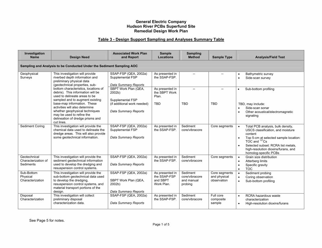
General Electric Company
Hudson River PCBs Superfund Site Remedial Design Work Plan
Table 3 - Design Support Sampling and Analyses Summary Table
See Page 5 for notes. Page 1 of 5
Investigation Name Design Need
Associated Work Plan and Report
Sample Locations
Sampling Method Sample Type Analysis/Field Test
Sampling and Analysis to be Conducted Under the Sediment Sampling AOC
SSAP-FSP (QEA, 2002a) Supplemental FSP Data Summary Reports
As presented in the SSAP-FSP.
-- -- • Bathymetric survey • Side-scan survey
Geophysical Surveys
This investigation will provide riverbed depth information and preliminary physical data (geotechnical properties, sub-bottom characteristics, locations of debris). This information will be used to delineate areas to be sampled and to augment existing base-map information. These activities will also determine whether geophysical techniques may be used to refine the delineation of dredge prisms and cut lines.
SBPT Work Plan (QEA, 2002b) Supplemental FSP (if additional work needed) Data Summary Reports
As presented in the SBPT Work Plan. TBD
--
TBD
--
TBD
• Sub-bottom profiling TBD, may include: • Side-scan sonar • Other acoustical/electromagnetic
signaling
Sediment Coring This investigation will provide the chemical data used to delineate the dredge areas. This will also provide some geotechnical information.
SSAP-FSP (QEA, 2002a) Supplemental FSP Data Summary Reports
As presented in the SSAP-FSP.
Sediment core/vibracore
Core segments • Total PCB analysis, bulk density, USCS classification, and moisture content
• Top 5-cm at selected sample location: TOC and 137Cs
• Selected subset: RCRA list metals, high-resolution dioxins/furans, and homolog-specific PCBs
Geotechnical Characterization of Sediments
This investigation will provide the sediment geotechnical information used to develop the dredging and resuspension control systems.
SSAP-FSP (QEA, 2002a) Data Summary Reports
As presented in the SSAP-FSP.
Sediment core/vibracore
Core segments • Grain size distribution • Atterberg limits • Specific gravity • TOC
Sub-Bottom Physical Characterization
This investigation will provide the sub-bottom geotechnical data used to develop the dredging, resuspension control systems, and material transport portions of the design.
SSAP-FSP (QEA, 2002a) SBPT Work Plan (QEA, 2002b) Data Summary Reports
As presented in the SSAP-FSP and SBPT Work Plan.
Sediment core/vibracore and manual probing
Core segments and physical observation
• Sediment probing • Coring observation • Sub-bottom profiling
Disposal Characterization
This investigation will collect preliminary disposal characterization data.
SSAP-FSP (QEA, 2002a) Data Summary Reports
As presented in the SSAP-FSP.
Sediment core/vibracore
Full core composite sample
• RCRA hazardous waste characterization
• High-resolution dioxins/furans
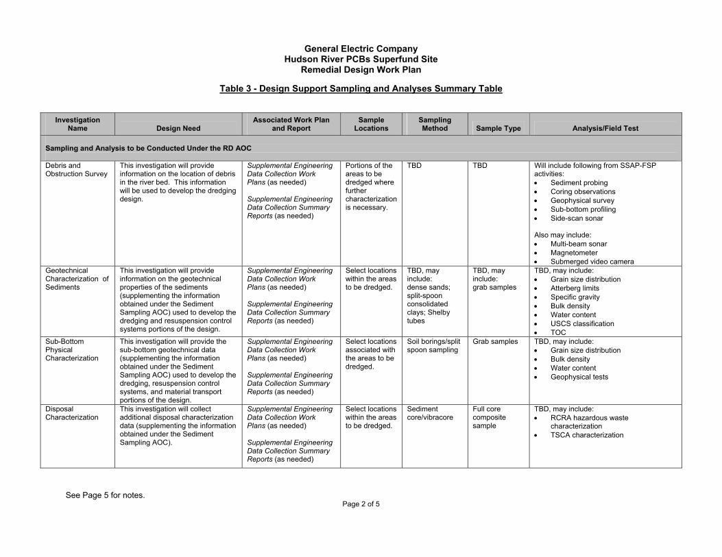
General Electric Company
Hudson River PCBs Superfund Site Remedial Design Work Plan
Table 3 - Design Support Sampling and Analyses Summary Table
See Page 5 for notes. Page 2 of 5
Investigation Name Design Need
Associated Work Plan and Report
Sample Locations
Sampling Method Sample Type Analysis/Field Test
Sampling and Analysis to be Conducted Under the RD AOC Debris and Obstruction Survey
This investigation will provide information on the location of debris in the river bed. This information will be used to develop the dredging design.
Supplemental Engineering Data Collection Work Plans (as needed) Supplemental Engineering Data Collection Summary Reports (as needed)
Portions of the areas to be dredged where further characterization is necessary.
TBD TBD Will include following from SSAP-FSP activities: • Sediment probing • Coring observations • Geophysical survey • Sub-bottom profiling • Side-scan sonar Also may include: • Multi-beam sonar • Magnetometer • Submerged video camera
Geotechnical Characterization of Sediments
This investigation will provide information on the geotechnical properties of the sediments (supplementing the information obtained under the Sediment Sampling AOC) used to develop the dredging and resuspension control systems portions of the design.
Supplemental Engineering Data Collection Work Plans (as needed) Supplemental Engineering Data Collection Summary Reports (as needed)
Select locations within the areas to be dredged.
TBD, may include: dense sands; split-spoon consolidated clays; Shelby tubes
TBD, may include: grab samples
TBD, may include: • Grain size distribution • Atterberg limits • Specific gravity • Bulk density • Water content • USCS classification • TOC
Sub-Bottom Physical Characterization
This investigation will provide the sub-bottom geotechnical data (supplementing the information obtained under the Sediment Sampling AOC) used to develop the dredging, resuspension control systems, and material transport portions of the design.
Supplemental Engineering Data Collection Work Plans (as needed) Supplemental Engineering Data Collection Summary Reports (as needed)
Select locations associated with the areas to be dredged.
Soil borings/split spoon sampling
Grab samples TBD, may include: • Grain size distribution • Bulk density • Water content • Geophysical tests
Disposal Characterization
This investigation will collect additional disposal characterization data (supplementing the information obtained under the Sediment Sampling AOC).
Supplemental Engineering Data Collection Work Plans (as needed) Supplemental Engineering Data Collection Summary Reports (as needed)
Select locations within the areas to be dredged.
Sediment core/vibracore
Full core composite sample
TBD, may include: • RCRA hazardous waste
characterization • TSCA characterization

General Electric Company
Hudson River PCBs Superfund Site Remedial Design Work Plan
Table 3 - Design Support Sampling and Analyses Summary Table
See Page 5 for notes. Page 3 of 5
Investigation Name Design Need
Associated Work Plan and Report
Sample Locations
Sampling Method Sample Type Analysis/Field Test
Backfill Source Material Identification and Characterization
This investigation will identify potential sources for backfill material and will provide information used to assess whether the material may be used as backfill material during the RA.
Supplemental Engineering Data Collection Work Plans (as needed) Supplemental Engineering Data Collection Summary Reports and/or design documents as appropriate
TBD TBD TBD TBD, but may include: • Grain size • TOC • Chemical characterization
Base-Mapping Activities
These activities will provide location and elevation data used in the preparation of drawings and specifications to support the remedial design (e.g., to present dredging cut lines, habitat delineations, and to determine backfilling requirements).
RD Work Plan The results for these activities will be incorporated into the engineering design documents.
-- -- -- Surveying and GIS as needed.
Baseline Monitoring Activities
These activities will provide baseline water quality and fish PCB data for comparison with data collected during and after remedial activities.
Baseline Monitoring Program Scoping Document (QEA, 2003), Baseline Monitoring QAPP, and Baseline Monitoring Data Summary Reports
As identified in the Baseline Monitoring Program Scoping Document.
As identified in the Baseline Monitoring Program Scoping Document.
As identified in the Baseline Monitoring Program Scoping Document.
As identified in the Baseline Monitoring Program Scoping Document.
Habitat Delineation and Assessment
This investigation will be conducted to document the range of existing conditions of ecological features at the site.
HDA Work Plan (BBL, 2003a) and Supplemental Engineering Data Collection Work Plans Habitat Delineation Reports, Habitat Assessment Reports, and BA
As identified in the HDA Work Plan.
As identified in the HDA Work Plan.
As identified in the HDA Work Plan.
As identified in the HDA Work Plan.
Cultural and Archaeological Assessment Resources
These activities will identify cultural and archaeological resources that may be impacted by RA activities.
CARA Work Plan (URS, 2003) Archaeological Resources Assessment Reports
As identified in the CARA Work Plan.
As identified in the CARA Work Plan.
As identified in the CARA Work Plan.
As identified in the CARA Work Plan.
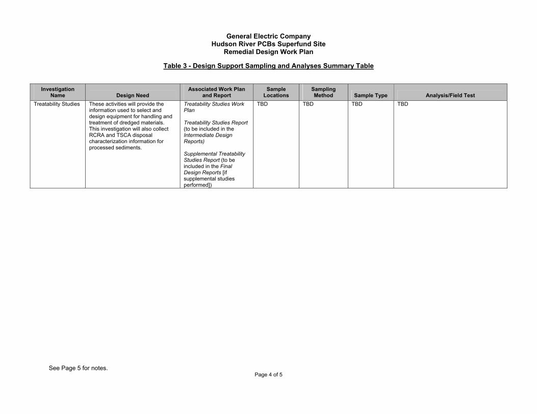
General Electric Company
Hudson River PCBs Superfund Site Remedial Design Work Plan
Table 3 - Design Support Sampling and Analyses Summary Table
See Page 5 for notes. Page 4 of 5
Investigation Name Design Need
Associated Work Plan and Report
Sample Locations
Sampling Method Sample Type Analysis/Field Test
Treatability Studies These activities will provide the information used to select and design equipment for handling and treatment of dredged materials. This investigation will also collect RCRA and TSCA disposal characterization information for processed sediments.
Treatability Studies Work Plan Treatability Studies Report (to be included in the Intermediate Design Reports) Supplemental Treatability Studies Report (to be included in the Final Design Reports [if supplemental studies performed])
TBD TBD TBD TBD

General Electric Company
Hudson River PCBs Superfund Site Remedial Design Work Plan
Table 3 - Design Support Sampling and Analyses Summary Table
Page 5 of 5
Notes:
1. -- = Not applicable. 2. A QAPP, HASP, CHASP, and appropriate supplements will be submitted with select above-referenced work plans as needed.
3. Acronyms:
AOC = Administrative Order on Consent BA = Biological Assessment CARA Work Plan = Cultural and Archaeological Resources Assessment Work Plan (URS, 2003) CHASP = Community Health and Safety Plan cm = centimeters Cs = Cesium GIS = Geographic information system HASP = Health and Safety Plan HDA Work Plan = Habitat Delineation and Assessment Work Plan (BBL, 2003a) PCB = Polychlorinated biphenyl QAPP = Quality Assurance Project Plan (QEA and ESI, 2002) RA = Remedial action RCRA = Resource Conservation and Recovery Act RD = Remedial design RD Work Plan = Remedial Design Work Plan SBPT Work Plan = Sub-Bottom Profiling Test Work Plan (QEA, 2002b) SSAP-FSP = Sediment Sampling and Analysis Program - Field Sampling Plan (QEA, 2002a) Supplemental FSP = Supplemental Field Sampling Plan TBD = To be determined TOC = Total organic carbon TSCA = Toxic Substances Control Act USCS = Unified Soil Classification System

General Electric Company
Hudson River PCBs Superfund Site Remedial Design Work Plan
Table 4 – Remedial Design Schedule
See Page 6 for notes.
Page 1 of 6
Activity Deadline
General 1. RD Work Plan Completed and approved prior to effective date of RD AOC and attached thereto. 2. Baseline Monitoring Program Scoping Document (for surface water
and fish) Completed and approved prior to effective date of RD AOC and attached to RD Work Plan.
3. HDA Work Plan Completed and approved prior to effective date of RD AOC and attached to RD Work Plan.
4. CARA Work Plan Completed and approved prior to effective date of RD AOC and attached to RD Work Plan.
5. Revised CHASP to cover RD data gathering efforts Completed and approved in June 2003 and appended to the RD AOC (Appendix 2). 6. Revised HASP to cover RD data gathering efforts 21 days after effective date of RD AOC. 7. Baseline Monitoring QAPP 30 days after effective date of RD AOC. Design Support Activities 8. Performance of Year 1 sediment sampling and side-scan sonar Per schedule under Sediment Sampling AOC. 9. Performance of sub-bottom profiling field test Per schedule in Sub-bottom Profiling Test Work Plan (as approved or modified by
USEPA). 10. Commencement of baseline monitoring program for water column
and fish 30 days after USEPA approval of Baseline Monitoring QAPP.
11. Submission of Data Summary Report for Year 1 to USEPA Completed. 12. Commencement of habitat delineation and assessment activities After effective date of RD AOC. Contingent on weather conditions and seasonal
constraints. 13. Commencement of cultural and archaeological resources
assessment After effective date of RD AOC.
14. Submission of Supplemental FSP and associated QAPP Addendum for Year 2 to USEPA
Per schedule under Sediment Sampling AOC.
15. Submission of Supplemental Engineering Data Collection Work Plan for Year 2 and associated QAPP, as well as HASP and CHASP Addenda (as needed) to USEPA
30 days after effective date of RD AOC.
16. Performance of sediment sampling, bathymetric surveys, and sub-bottom profiling (if necessary) for Year 2
Per schedule under Sediment Sampling AOC.

General Electric Company
Hudson River PCBs Superfund Site Remedial Design Work Plan
Table 4 – Remedial Design Schedule
See Page 6 for notes.
Page 2 of 6
Activity Deadline 17. Performance of engineering data collection for Year 2 Per schedule in Supplemental Engineering Data Collection Work Plan for Year 2 (as
approved or modified by USEPA). 18. Submission of Supplemental Data Summary Report for candidate
Phase 1 areas to USEPA 90 days after completion of sampling in candidate Phase 1 areas.
19. Submission of Phase 1 Dredge Area Delineation Report (covering candidate Phase 1 areas) to USEPA
30 days after submittal of Supplemental Data Summary Report for candidate Phase 1 areas or 30 days after effective date of RD AOC, whichever is later.
20. Submission of Phase 1 Target Area Identification Report to USEPA Simultaneously with Phase 1 Dredge Area Delineation Report or Preliminary Design Report, whichever is later.
21. Submission of Archaeological Resources Assessment Report for candidate Phase 1 areas to USEPA
30 days after USEPA approval of Phase 1 Dredge Area Delineation Report.
22. Submission of Habitat Delineation Report and Habitat Assessment Report for candidate Phase 1 areas to USEPA
8 months after effective date of RD AOC. Contingent on seasonal constraints.
23. Submission of Data Summary Report for Year 2 to USEPA Per schedule in Sediment Sampling AOC. 24. Submission of Year 2 Dredge Area Delineation Report to USEPA 30 days after USEPA approval of Data Summary Report for Year 2. 25. Submission of Supplemental Engineering Data Collection Summary
Report for Year 2 to USEPA Per schedule in Supplemental Engineering Data Collection Work Plan for Year 2 (as approved or modified by USEPA).
26. Submission of Supplemental Engineering Data Collection Work Plan for Year 3 and QAPP, HASP, and CHASP addenda (as needed) to USEPA
30 days after USEPA approval of Year 2 Dredge Area Delineation Report.
27. Submission of Archaeological Resources Assessment Report for Year 2 (covering areas covered by Year 2 Dredge Area Delineation Report) to USEPA
90 days after USEPA approval of Year 2 Dredge Area Delineation Report.
28. Performance of engineering data collection for Year 3 Per schedule in Supplemental Engineering Data Collection Work Plan for Year 3 (as approved or modified by USEPA).
29. Submission of Supplemental Engineering Data Collection Summary Report for Year 3 to USEPA
Per schedule in Supplemental Engineering Data Collection Work Plan for Year 3 (as approved or modified by USEPA).
30. Submission of Habitat Assessment Report for Year 2 (covering areas covered by Year 2 Dredge Area Delineation Report) to USEPA
Same as deadline for Supplemental Engineering Data Collection Report for Year 3.

General Electric Company
Hudson River PCBs Superfund Site Remedial Design Work Plan
Table 4 – Remedial Design Schedule
See Page 6 for notes.
Page 3 of 6
Activity Deadline 31. Submission of BA to USEPA 90 days after the later of:
• USEPA’s issuance to the public of the draft engineering performance standards; or • USEPA’s issuance to the public of the list of final candidate sites for the sediment
processing/transfer facility(ies) for Phase 1 and Phase 2. 32. Submission of supplemental Dredge Area Delineation Report,
Archaeological Resources Assessment Report, and/or Habitat Assessment Report for Phase 2 dredge areas (if necessary to complete these activities for Phase 2 areas)
If necessary, per schedule in Year 2 Dredge Area Delineation Report or Supplemental Engineering Data Collection Work Plan for Year 3 (as approved or modified by USEPA).
33. Submission of Treatability Studies Work Plan (and associated QAPP, HASP and CHASP addenda if necessary) to USEPA
120 days after effective date of RD AOC.
34. Commencement of treatability studies Per schedule in Treatability Studies Work Plan (as approved or modified by USEPA). 35. Completion of treatability studies Per schedule in Treatability Studies Work Plan (as approved or modified by USEPA). 36. Performance and reporting of supplemental treatability studies (if
necessary) Per schedule relating to treatability studies in relevant Intermediate Design Report (as approved or modified by USEPA).
37. Submission of Baseline Monitoring Data Summary Reports to USEPA
Annually, by April 1 of each calendar year following baseline monitoring activities.
Engineering Design 38. Submission of Preliminary Design Report to USEPA 120 days after effective date of RD AOC. 39. Commencement of Phase 1 Intermediate Design Upon receipt of USEPA’s Draft Facility Siting Report or USEPA approval of Preliminary
Design Report, whichever is later. 40. Submission of Phase 1 Intermediate Design Report, including
results of Value Engineering Study, to USEPA The latest of: EITHER: 180 days after the latest of: • USEPA approval of Phase 1 Target Area Identification Report; • Establishment of finalized engineering performance standards and quality of life
performance standards; • Final determination of any limitations or requirements applicable to releases of
constituents not subject to performance standards; • USEPA approval of Phase 1 Dredge Area Delineation Report; and • USEPA approval of Preliminary Design Report; OR: 90 days after the later of: • USEPA selection of sediment processing/transfer facility sites(s) for Phase 1; or • Completion of treatability studies.

General Electric Company
Hudson River PCBs Superfund Site Remedial Design Work Plan
Table 4 – Remedial Design Schedule
See Page 6 for notes.
Page 4 of 6
Activity Deadline 41. Submission of Phase 1 Final Design Report to USEPA
The latest of: EITHER: 120 days after the latest of: • USEPA approval of Phase 1 Intermediate Design Report; • USEPA approval of Archaeological Resources Assessment Report for candidate
Phase 1 areas; • USEPA approval of the Supplemental Engineering Data Collection Summary
Report for Year 2, as it relates to candidate Phase 1 areas; and • USEPA approval of Habitat Assessment Report for candidate Phase 1 areas OR: 90 days following receipt of assurance from USEPA that USEPA intends to acquire a property interest in the selected sediment processing/transfer facility site(s) for Phase 1; OR: 60 days after the latest of: • Receipt of final BOs or written concurrence by USFWS and NMFS with a “not likely
to adversely affect” determination in the BA and a determination by USEPA, if necessary, as to related measures necessary to be incorporated into the design;
• USEPA approval of Year 2 Dredge Area Delineation Report; and • Completion of any supplemental treatability studies proposed in Phase 1
Intermediate Design Report. 42. Submission of RA CHASP and Environmental Monitoring Plan for
Phase 1 to USEPA Simultaneously with Phase 1 Final Design Report.
43. Commencement of Phase 2 Intermediate Design Upon receipt of USEPA approval of Year 2 Dredge Area Delineation Report. 44. Submission of Phase 2 Intermediate Design Report, including
results of Value Engineering Study, to USEPA The latest of: EITHER: 180 days after the later of: • USEPA approval of Phase 1 Intermediate Design Report; and • USEPA approval of all Dredge Area Delineation Reports for Phase 2 dredge
areas; OR: 90 days after USEPA selection of sediment processing/transfer site(s) for Phase 2

General Electric Company
Hudson River PCBs Superfund Site Remedial Design Work Plan
Table 4 – Remedial Design Schedule
See Page 6 for notes.
Page 5 of 6
Activity Deadline 45. Submission of Phase 2 Final Design Report to USEPA The latest of
EITHER: 120 days after the latest of: • USEPA approval of Phase 2 Intermediate Design Report; • USEPA approval of all Archaeological Resources Assessment Reports for Phase 2
dredge areas; • USEPA approval of all Supplemental Engineering Data Collection Summary
Reports for Phase 2 dredge areas; and • USEPA approval of all Habitat Assessment Reports for Phase 2 dredge areas; OR: 90 days following receipt of assurance from USEPA that USEPA intends to acquire a property interest in the selected sediment processing/transfer facility site(s) for Phase 2; OR: 60 days after completion of any supplemental treatability studies proposed in Phase 2 Intermediate Design Report.
46. Submission of RA CHASP and Environmental Monitoring Plan for Phase 2 to USEPA
Simultaneously with Phase 2 Final Design Report.

General Electric Company
Hudson River PCBs Superfund Site Remedial Design Work Plan
Table 4 – Remedial Design Schedule
Page 6 of 6
Notes:
1. Acronyms:
AOC = Administrative Order on Consent BA = Biological Assessment BO = Biological Opinion CARA Work Plan = Cultural and Archaeological Resources Assessment Work Plan (URS, 2003) CHASP = Community Health and Safety Plan HASP = Health and Safety Plan HDA Work Plan = Habitat Delineation and Assessment Work Plan (BBL, 2003a) NMFS = National Marine Fisheries Service QAPP = Quality Assurance Project Plan (QEA and ESI, 2002) RA CHASP = Remedial Action Community Health and Safety Plan RD = Remedial Design RD Work Plan = Remedial Design Work Plan Revised CHASP = Revised Community Health and Safety Plan (BBL, 2003b) Revised HASP = Revised Health and Safety Plan Supplemental FSP = Supplemental Field Sampling Plan USEPA = United States Environmental Protection Agency USFWS = United States Fish and Wildlife Service
2. Assumes USEPA approval includes any public review and comment that the USEPA deems necessary. 3. For purposes of this schedule, USEPA approval of a deliverable means approval of that entire deliverable except as provided in Para. 54 of the RD AOC. 4. All deadlines may be extended upon approval of USEPA.

Figure
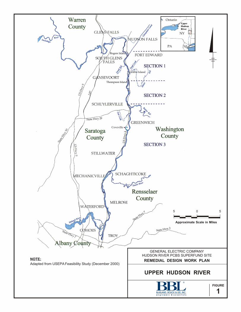
UPPER HUDSON RIVER
FIGURE
1
NOTE:
Adapted from USEPA Feasibility Study (December 2000)
GENERAL ELECTRIC COMPANYHUDSON RIVER PCBS SUPERFUND SITE
REMEDIAL DESIGN WORK PLAN
Approximate Scale in Miles
5 0 5
UpperHudsonRiver
Coveville