Enterprise PaaS, Cloud-Native Architecture and Microservices

HAL Id: tel-02143040https://tel.archives-ouvertes.fr/tel-02143040
Submitted on 29 May 2019
HAL is a multi-disciplinary open accessarchive for the deposit and dissemination of sci-entific research documents, whether they are pub-lished or not. The documents may come fromteaching and research institutions in France orabroad, or from public or private research centers.
L’archive ouverte pluridisciplinaire HAL, estdestinée au dépôt et à la diffusion de documentsscientifiques de niveau recherche, publiés ou non,émanant des établissements d’enseignement et derecherche français ou étrangers, des laboratoirespublics ou privés.
Reliability of changes in cloud environment at PaaS levelXinxiu Tao
To cite this version:Xinxiu Tao. Reliability of changes in cloud environment at PaaS level. Hardware Architecture [cs.AR].Université Grenoble Alpes, 2019. English. �NNT : 2019GREAM001�. �tel-02143040�

THÈSEPour obtenir le grade de
DOCTEUR DE LA COMMUNAUTE UNIVERSITE GRENOBLE ALPESSpécialité : InformatiqueArrêté ministériel : 25 mai 2016
Présentée par
Xinxiu TAO
Thèse dirigée par Fabienne BOYER, MCF, LIG / UGAet codirigée par Noël DE PALMA, Professeur, LIG / UGAet Xavier ETCHEVERS, Ingénieur de Recherche, Orange Labs
préparée au sein du Laboratoire LIG et de Orange Labsdans l'École Doctorale Mathématiques, Sciences ettechnologies de l'information, Informatique
Fiabilisation des mises à jour dans le Cloud au niveau Platform as a Service
Reliability of changes in cloud environment at PaaS level
Thèse soutenue publiquement le 29 janvier 2019,devant le jury composé de :
Madame Françoise BaudeProfesseur, CNRS, RapporteurMonsieur Lionel SeinturierProfesseur, Inria, RapporteurMonsieur Daniel HagimontProfesseur, IRIT/ENSEEIHT, PrésidentMonsieur Thomas LedouxEnseignant-chercheur, IMT Atlantique, ExaminateurMadame Fabienne BOYERMaître de Conférences, LIG/UGA, Directeur de thèseMonsieur Noël de PalmaProfesseur, LIG/UGA, Co-directeur de thèseMonsieur Xavier EtcheversIngénieur de Recherche, Orange Labs, Co-directeur de thèse

Abstract
Microservice architectures are considered with much promises to achieveDevOps in IT organizations, because they split applications into servicesthat can be updated independently from each others. But to protect SLA(Service Level Agreement) properties when updating microservices, DevOpsteams have to deal with complex and error-prone scripts of management op-erations to perform an update. More precisely, update scripts have to followparticular strategies, such as the the well-known BlueGreen strategy [1] thatintends to update a microservice with zero downtime, but requires deployingand starting all the new microservices before stopping and uninstalling theold ones. In comparison, the Canary strategy [2] minimizes the resourcesused at update time, at the expense of a reduced availability: microservicesare updated in-place (new instances taking the place of the old ones), in anincremental manner to slowly transfer the load from the current to the newversion.
In this thesis, we propose an update framework [3, 4] that leverages anarchitecture-based approach to provide an easy and safe way to update mi-croservices and program strategies. Instead of scripts processing PaaS com-mands, update strategies are defined as sequences of elementary changesbeing applied on an architectural model of a microservice application. Sim-ply put, this architectural model reflects how microservices are deployed onPaaS sites and how they are configured.
Leveraging an architecture-based approach raises two main challenges:(i) determining an architectural model encompassing microservices deployedon heterogeneous PaaS sites and (ii) defining a strategy-driven update pro-tocol relying on this architectural model.
The following of these document describes how these challenges wereaddressed to provide an update framework that can add, remove, migrate,split, or scale microservices as well as upgrade their code or change theirconfiguration across distributed and potentially heterogeneous PaaS sites.
i

Contents
1 Introduction 1
2 Problem Position 32.1 Microservices . . . . . . . . . . . . . . . . . . . . . . . . . . . 52.2 Cloud Computing . . . . . . . . . . . . . . . . . . . . . . . . . 7
2.2.1 Resources Virtualization . . . . . . . . . . . . . . . . . 72.2.2 Cloud Services Models . . . . . . . . . . . . . . . . . . 82.2.3 PaaS/CaaS layers and microservices . . . . . . . . . . 9
2.3 Continuous Delivery . . . . . . . . . . . . . . . . . . . . . . . 112.4 Motivation and Objectives . . . . . . . . . . . . . . . . . . . . 132.5 Challenges . . . . . . . . . . . . . . . . . . . . . . . . . . . . . 15
3 State of the Art 173.1 Existing approaches for dynamic software updates . . . . . . 18
3.1.1 DSU . . . . . . . . . . . . . . . . . . . . . . . . . . . . 183.1.2 Components . . . . . . . . . . . . . . . . . . . . . . . 183.1.3 Actors . . . . . . . . . . . . . . . . . . . . . . . . . . . 19
3.2 Existing approaches for dynamic updates of Microservices . . 193.2.1 Comparison grid . . . . . . . . . . . . . . . . . . . . . 193.2.2 Spinnaker . . . . . . . . . . . . . . . . . . . . . . . . . 203.2.3 IBM UrbanCode Deploy . . . . . . . . . . . . . . . . . 233.2.4 AWS CodeDeploy . . . . . . . . . . . . . . . . . . . . 263.2.5 Push2cloud . . . . . . . . . . . . . . . . . . . . . . . . 273.2.6 Other related approaches for managing Microservices . 293.2.7 Summary . . . . . . . . . . . . . . . . . . . . . . . . . 30
4 Proposition 344.1 Usage Principles . . . . . . . . . . . . . . . . . . . . . . . . . 364.2 Architectural Model . . . . . . . . . . . . . . . . . . . . . . . 38
4.2.1 Data-Structure . . . . . . . . . . . . . . . . . . . . . . 384.2.2 Elementary Operations . . . . . . . . . . . . . . . . . 394.2.3 Introspection and Reconfiguration of a Microservice
Application . . . . . . . . . . . . . . . . . . . . . . . . 41
ii

Contents
4.3 Strategy-driven Updates . . . . . . . . . . . . . . . . . . . . . 454.3.1 Update Process Overview . . . . . . . . . . . . . . . . 454.3.2 Strategy-driven Update Protocol . . . . . . . . . . . . 46
4.4 Strategy Programming . . . . . . . . . . . . . . . . . . . . . . 494.4.1 Strategy Design . . . . . . . . . . . . . . . . . . . . . . 494.4.2 Didactic case: the BlueGreen Strategy . . . . . . . . . 51
4.5 Update Robustness . . . . . . . . . . . . . . . . . . . . . . . . 544.5.1 Core principles . . . . . . . . . . . . . . . . . . . . . . 544.5.2 Identification of faults . . . . . . . . . . . . . . . . . . 564.5.3 Summary . . . . . . . . . . . . . . . . . . . . . . . . . 61
5 Evaluation 645.1 SLA protection . . . . . . . . . . . . . . . . . . . . . . . . . . 65
5.1.1 Lizard application . . . . . . . . . . . . . . . . . . . . 655.1.2 Account application . . . . . . . . . . . . . . . . . . . 68
5.2 Robustness . . . . . . . . . . . . . . . . . . . . . . . . . . . . 705.2.1 Network faults . . . . . . . . . . . . . . . . . . . . . . 725.2.2 Update process faults . . . . . . . . . . . . . . . . . . 745.2.3 Erroneous strategy . . . . . . . . . . . . . . . . . . . . 755.2.4 Microservice faults . . . . . . . . . . . . . . . . . . . . 78
5.3 Ease of use . . . . . . . . . . . . . . . . . . . . . . . . . . . . 795.3.1 Programming Strategies . . . . . . . . . . . . . . . . . 805.3.2 Updating Microservices . . . . . . . . . . . . . . . . . 815.3.3 Comparison with an imperative approach . . . . . . . 83
6 Conclusion 866.1 Conclusions . . . . . . . . . . . . . . . . . . . . . . . . . . . . 866.2 Limitations and Future Works . . . . . . . . . . . . . . . . . . 88
Bibliography 95
iii

Chapter 1
Introduction
To facilitate agile development and operations (DevOps), many companies,including established ones such as Netflix [5] and Uber [6], are switching to amicroservice architecture for their Cloud applications. For example, by 2020,Orange aims at migrating about 50% of its production applications –thatserve 240 million customers worldwide– to the microservice architecture [7].With the microservice approach, applications are designed as loosely-coupledservices deployed on distributed PaaS (Platform-as-a-Service) sites and run-ning in their own full-stack [8].
The key property that is expected from microservices is the notion ofindependent replacement and updatability. Especially, microservices exhibitindependent lifecycles: they can be deployed and updated independentlyfrom each others. The objective is to favor reactivity of small developmentteams, each team being in charge of developing and evolving its own set ofmicroservices through simple and fast processes.
Such an objective is attractive, but the reality is much more complex be-cause microservices are often associated to SLA properties regarding avail-ability, performances, and resource costs [9, 10]. To keep these propertiesat update time, DevOps teams follow complex strategies. Typically, thewell-known BlueGreen strategy [1] intends to update a microservice withzero downtime, but requires deploying and starting all the new microservicesbefore stopping and uninstalling the old ones. In comparison, the Canarystrategy [2, 11] minimizes the resources used at update time, at the expenseof a reduced availability: microservices are updated in-place (new instancestaking the place of the old ones), in an incremental manner to slowly transferthe load from the current to the new version.
Using strategies to update microservices is considered relevant [12], butso far, the process is managed manually or only automated through usingscripts [13]. Scripts provide flexibility but their imperative form limits theirease of use. When DevOps teams are provided with application-independentscripts, they have to determine what script can be applied to process a givenupdate. Furthermore, they must check that the current state of their appli-
1

Introduction
cation meets the requirements of the chosen script. This is cumbersome anderror-prone as most update scripts encompass complex pipelines of PaaScommands. When update scripts are designed specifically for a given ap-plication, they can be used in a much easier and safer way, but the price isthat DevOps teams have to compose these scripts, facing the usual codingand debugging challenges.
This thesis advocates switching from a script-based to an architecture-based approach to automate microservices updates: instead of scripts pro-cessing PaaS commands, update strategies are defined as sequences of el-ementary changes being applied on an architectural model of a microser-vice application. Simply put, this architectural model (also known asmodel@runtime [14]) reflects how microservices are deployed on PaaS sitesand how they are configured. Compared to scripts, the expected benefits ofthe proposed approach are the following:
• ease of use: to update a microservice application, DevOps teams sim-ply give as input the desired target architecture, along with the strat-egy to follow, without having to deal with low-level PaaS commands.
• preview: any update can be processed on the architectural model with-out being applied on the effective system, allowing to preview its resultin terms of architectural changes.
• control: all stages of an update can be observed on the architecturalmodel. Moreover, at any stage an update can be stopped and resumedwith a new target architecture and/or strategy.
• robustness: failures occurring at update time are supported.
The remaining of this document is organized as follow.
• Chapter 2 introduces the background of the problem, our objectivesand the main associated challenges.
• Chapter 3 reports on the related research works about dynamic up-date, and compares current industrial solutions for managing the up-dates of microservices application.
• Chapter 4 presents the proposed framework for updating microservicesapplication through an architecture-based approach.
• Chapter 5 presents the evaluation of our framework.
• Chapter 6 concludes this document by summarizing our main propo-sitions and outlining future works.
2

Chapter 2
Problem Position
Contents2.1 Microservices . . . . . . . . . . . . . . . . . . . . . 52.2 Cloud Computing . . . . . . . . . . . . . . . . . . 7
2.2.1 Resources Virtualization . . . . . . . . . . . . . . . 72.2.2 Cloud Services Models . . . . . . . . . . . . . . . . 82.2.3 PaaS/CaaS layers and microservices . . . . . . . . 9
2.3 Continuous Delivery . . . . . . . . . . . . . . . . . 112.4 Motivation and Objectives . . . . . . . . . . . . . 132.5 Challenges . . . . . . . . . . . . . . . . . . . . . . . 15
Change management is nowadays a well-known term referring to theaction of evolving a software system towards a new version, such new ver-sion integrating changes in the structure, the code or the configuration ofthe system. The change management is becoming more and more crucialin the application lifecycle, whatever software development methodology isfollowed to design, develop and test applications.
The waterfall methodology [15] is a well-known linear software devel-opment approach that splits the software development into several well-known phases: analyze requirements, design, code, test and maintain. Thismethodology promotes spending much time on the early phases to reducethe risk of changes. Anyway, change requirements will appear over time andwill need to be managed with minimal impacts on the application.
Compared to the traditional waterfall approach, current popular Agilemethodologies [16] promotes embracing changes instead of reducing them.By frequently delivering small changes to end clients, Agile development canbetter fit to customers’ changing requirements, shortening the feedback loopwith customers and avoiding the risk inherent in big changes. In this thesis,we address the change management in the specific case of Agile approaches,but the principles of our proposal can be applied in a more general case.
Multiple paradigms help to enforce the Agile methodology:
3

Problem Position
• Microservices application architecture: by decoupling applicationsinto independently-deployable units, microservices intend to reducethe cost of application changes.
• Cloud environments: they provide on-demand underlying infrastruc-ture for deploying and executing microservices-based applications.
• Continuous delivery discipline: it implies that every change can beautomatically released into the production environments.
The rest of this section presents these main paradigms and then explicitsthe challenges addressed in this thesis.
4

Problem Position
2.1 Microservices
As previously said, there is no standard definition for microservices, butcommon guidelines influencing how distributed applications should be de-signed, developed and managed. Thus, microservices can be considered as aset of architectural patterns for designing applications, aiming at simplifyingtheir deployment and management.
In more precise terms, a microservice-based architecture constructs anapplication as a set of loosely coupled units called microservice. Each mi-croservice is associated to well-defined business capabilities (e.g., productcatalog management, order management). Based on this, each microserviceis responsible for managing the data and processing the requests associatedto its business capability. More precisely, each microservice may expose itsfunctionalities through provided services and may consume services providedby others microservices (i.e. required services).
A very important aspect of microservices is their lifecycle independence.Indeed, the microservices of a given application have independent lifecyclesin the sense that each microservice can be independently deployed, scaledand updated [17]. To achieve this, each microservice is packaged as a self-contained deployment and execution unit. Such a package encompassesoperating system, runtime, frameworks, libraries, and microservice artifact(source code and configuration files).
The lifecycle independence of microservices favors their decentralizedgovernance, a key capability regarding Agile methodologies. Each microser-vice can indeed be independently developed and operated by a specifiedsmall team. Each team is responsible for the technical and technologicalchoices (e.g., programming language, database solution, test and deliverytools) to build its own microservice and do not depend on any other exter-nal decision.
To promote this lifecycle independence, three main design patterns areused by microservice architectures:
• The data management in the microservice architecture is decentral-ized. While monolithic applications prefer a single database for per-sistent data, microservices prefer letting each service manage its owndatabase instance. Each microservice is in charge of encapsulating,governing, and protecting its own database. This decomposition al-lows each microservice to choose different data stores based on datashape and read/write access patterns.
• Microservices communicate through lightweight protocols, such asHTTP REST request-response or asynchronous messaging bus. Whena microservice instance starts running, it can publish its services as
5

Problem Position
Web services, and register its address and endpoints at a registry 1,such as Consul [18], Apache ZooKeeper [19] or Netflix Eureka [20].The microservice instance is unregistered from the registry when it isunavailable 2. Through the registry, clients of a microservice can knowat any time about the available instances of a microservice with theaddress information allowing to access them.
• Microservices tolerate the unavailability of the services they consume(i.e. accessed services). This capability relies on conforming to dedi-cated patterns [21] (such as Circuit Breaker, Bulkhead, and Timeout)when designing microservices. Several programming libraries (e.g.,Hystrix [22], Finagle [23], Phantom [24]) are available to simplify thedevelopment of these patterns. For example, the developer can easilydefine a fallback function of its accessed service, so that the microser-vice could get a fallback response when the accessed service is unavail-able. In addition, the administrator of the microservice can deploymultiple redundant and distributed instances and use smart proxiesto achieve high availability of the microservice. Smart proxies managethe cases where an accessed service is unavailable. Most commonly,depending on the SLA properties of the accessed microservice, a proxymay either (i) select another service instance, (ii) wait for the serviceto be restored, or (iii) produce a by-default reply.
Overall, through splitting the application into a set of independentlydeployable services, the microservice architecture minimizes the impactsof changes on a running application. With classical monolithic applica-tions, applying a change to any single module often requires to redeploythe entire application. Conversely, in the microservice-oriented approach,single service changes only imply to redeploy the considered microservice.In other words, the microservice architecture aims at decoupling the appli-cation change cycle.
1The registry service is usually deployed and consumed by a specific application.2Service registration and unregistration may be either managed by the microservice,
or automatically performed by the underlaying PaaS upon starting and stopping the mi-croservice.
6

Problem Position
2.2 Cloud Computing
Cloud environments enable consumers to run their application in a centrallymanaged data center. Instead of investing new physical hardware resourcesto satisfy the requirements of an application, a consumer can only rent thenecessary compute, storage, and network resources from the Cloud provider.Thanks to virtualization and autonomous management capabilities providedby cloud environments, consumers can operate the deployment of their ap-plication in a self-service manner. In addition, cloud environments helpconsumers to construct a highly available and scalable application throughusing redundancy and elasticity techniques at runtime [25].
This section starts by giving an insight of virtualization techniques andtechnologies. It then introduces the different cloud service models, andfinally focuses on the Platform as a Service (PaaS) layer specifically, as thislayer targets is the one concerned with microservices.
2.2.1 Resources Virtualization
The key technology of cloud computing is virtualization. Through logicallyseparating physical resources into several virtual resources, virtualizationfacilitates sharing hardware resources. There are currently two main virtu-alization levels: virtual machine (VM) and container. In addition to dividingsystem resources, these two techniques can also be used to package an ap-plication into a portable self-contained unit. Especially, they are currentlyboth used for packaging and deploying microservices.
In the VM-based approach, hardware IT resources (i.e. compute, mem-ory, storage) are packaged within software units (namely a virtual machineor VM) whose behavior imitates a physical machine environment. The appli-cation administrator can package the application running environment intoa VM, which contains a full software stack including the operating system(OS), middleware, and the application binaries and configuration elements.Then, the VM can be executed on any physical machine using a hypervi-sor. Since the VM provides the virtualization at the hardware level, theadministrator has the same experience on a VM as on a dedicated physicalmachine.
The container-based virtualization approach takes place at the operat-ing system level. The OS kernel and possibly some middleware are sharedacross all the containers running on a common host machine. Accordingly,the application administrator packages only some specific middleware andthe application with the container. Therefore, the container includes a quitereduced software stack and does not require a full system boot to be instan-tiated. Due to their reduced software stack, containers are smaller in termsof size and faster to start up compared to VMs. However, at the opposite,VM-based approaches provide more security because of greater isolation and
7

Problem Position
fully self-contained. Thus, in order to benefit from the advantages of bothapproaches, it can be relevant to combine them [26].
2.2.2 Cloud Services Models
According to the NIST’s definition [27], cloud environments are divided intothree standard service models based on the service abstraction level as shownin Figure 2.1.
Application
Middleware
Operating System
Virtualization
Server
Storage
Networking
IaaS
PaaS
SaaS
Figure 2.1: Cloud service models. Adapted from [28]
• Infrastructure as a Service (IaaS): at this level, the Cloud provideroffers virtualized hardware (e.g., virtualized machines, networks) tothe consumer. The control and the responsibility of the applicationoperation are fully given to the consumer. Some examples of IaaSoffers are Amazon Elastic Compute Cloud (Amazon EC2) [29], GoogleCompute Engine (GCE) [30], OpenStack [31].
• Platform as a Service (PaaS): the Cloud provider offers the run-ning environment of the application, the consumers providing onlytheir application code. It is the responsibility of the provider to in-stall the OS and middleware layers for building the application envi-ronment. Compared to the IaaS model, the consumer has less con-trol on the infrastructure. Some examples of PaaS offers are GoogleApp Engine [32], AppScale [33], OpenShift [34], Heroku [35], CloudFoundry [36].
• Software as a Service (SaaS): the Cloud provider completely man-ages the application. The consumer is the end user of the application.Some examples of SaaS offers are Gmail and Dropbox.
In addition to these three classic service models, Container as a Ser-vice (CaaS) offerings emerge, such as Google Kubernetes Engine [37],Amazon EC2 Container Service (ECS) [38], Azure Container Service [39].
8

Problem Position
As a service model positioned between infrastructure-centric IaaS andapplication-centric PaaS, CaaS is container-centric, meaning that it offerscontainers as a running environment for an application.
As in PaaS, CaaS also contains orchestration tools (e.g., Kubernetes [40],Apache Mesos [41], and Docker Swarm [42]) for the deployment and clustermanagement of containers. Moreover, CaaS usually also provides a containerimage registry and API support for facilitating the management of containerruntime. Anyway, unlike PaaS, the CaaS customers stay in charge of pack-aging their application within containers. An advantage of this is that CaaSdoesn’t constrain application programming languages or frameworks.
2.2.3 PaaS/CaaS layers and microservices
PaaS and CaaS service layers are intrinsically linked to microservices becausethey offer an easy way to deploy and run microservice. In the PaaS model,the expected user experience is that PaaS customers are only in charge oftheir code. In the CaaS layer, the customers have also the responsibility ofpackaging their code, but the deployment is taken in charge by the CaaSlayer. Overall, both layers take the responsibility for installation, config-uration, and operation (e.g., routing, monitoring, scaling) of applicationscomposed of microservices.
Typical elementary deployment operations provided by PaaS/CaaS lay-ers are the following:
• create: install a microservice (downloading its code, etc.,.)
• compile: compile a microservice
• start: start a microservice (launching one or more microservice in-stances)
• stop: stop a microservice (stopping one or more microservice instances)
• scale: scale a microservice (adding or removing one or more microser-vice instances)
• change: change a microservice’s configuration (stopping and restartingit if necessary)
• remove: uninstall a microservice
As previously said, a major functionality of PaaS/CaaS layers is to au-tomate the application deployment. Currently, several PaaS solutions (e.g.,Heroku, Cloud Foundry, OpenShift) provides a push-to-deploy capability.That is, consumers can deploy their application with a single push com-mand.
9

Problem Position
Especially, PaaS/CaaS customers can easily deploy multiple instancesof an application to achieve its high availability. During the execution ofapplications, PaaS solutions are indeed in charge of maintaining the healthof deployed application instances. To this end, PaaS solutions monitor thestate of application instances and automatically heal 3 the failed instances.The monitoring mechanism depends on the application types. Web appli-cation are classically monitored by sending periodic requests and expectingthe responses within a timeout. Applications without connections are mon-itored by checking the running state of their processes. PaaS customerscan configure the healing policy (e.g., restart) for the detected unhealthyinstances.
Another common capability of PaaS/CaaS layers is to manage the scal-ing of applications (while PaaS may manage the scalability in an autonomicway, this is however not yet true for CaaS layers). PaaS customers can hor-izontally scale their application through configuring the instances number.When the instance number is changed, the PaaS is in charge of deploying orremoving the instances. PaaS customers may also vertically scale the disk ormemory limit of all the instances. Several PaaS solutions (e.g., OpenShift,GAE) support automatic scaling according to the application workload. Thescaling policy is usually based on a set of rules and some application metrics(e.g., CPU utilization, request rate, response latency).
In addition, PaaS layers usually automates the network managementof the application. PaaS customers can configure one or multiple URLsfor accessing the application. PaaS solutions then take the responsibilityof routing the clients’ requests from these URLs to a running instance ofthe corresponding application. PaaS solutions may also provide build-inload balancing across multiple application instances. For example, CloudFoundry directs the requests in a round-robin 4 manner. To support morecomplex routing policies, PaaS customers may use an external routing ser-vice.
To sum up, although PaaS/CaaS solutions use different implementa-tion technologies, several common capabilities (e.g., deployment, replication,health check, scaling, and network management) are provided in most popu-lar PaaS/CaaS solutions. They provide elementary operations for managingeach aspect (usually modeled as a microservice attribute) of a microservice.Because microservices are managed by PaaS/CaaS layers, they naturallybenefit from these capabilities.
3Depending on the case, PaaS may migrate or restart a application instance4Round-robin means that the router forwards each client request for a given route to
each application instance in turn.
10

Problem Position
2.3 Continuous Delivery
As a software development discipline, Continuous delivery designates theability to release every application changes into production 5. In the agiledevelopment, continuous delivery is a critical requirement. Without theability to deliver small and frequent releases to end clients, the benefitsof agile development cannot be fully realized. This requirement has leadto the notion of DevOps teams, that are composed of a mix of developersand administrators, or at least people that can do both work, for achievingcontinuous delivery.
The complete delivery process involves building the deployable packages,deploying and testing them in increasingly production-like environments,and finally deploying into production. To improve time efficiency and avoidhuman errors, DevOps teams need to automate this delivery process. Thecurrent best practice is to model the delivery process into a deploymentpipeline [43]. Several popular tools are available for setting up deploymentpipelines, such as Jenkins [44], Concourse [45], GoCD [46].
The pipeline tool provides the utilities to construct a repeatable processthrough defining the steps and the connections between these steps. Eachstep is an elementary job with specified inputs, outputs, and properties.The pipeline tools support multiple types of connection between steps. Thesteps could be started either automatically as soon as the forward dependingsteps are completed successfully, or manually after a human approval.
Figure 2.2 illustrates a typical deployment pipeline. This pipeline au-tomatically detects the code change of an application, when the change isdetected, it retrieves the code from the Git server, build an image, executesthe automatic test, if the test passes, deploys the image to two PaaS sitesin parallel, and finally executes a manual test to valid the deployment.
Figure 2.2: An example of deployment pipeline
The pipeline tools give the DevOps teams the visibility and the control-lability of the process execution. The pipeline usually provides a graphicinterface to visualize the progress of the process execution. In addition, itshows whether the past steps have failed or succeeded. The DevOps teamscan start, pause, and stop the pipeline during its execution. The DevOpsteams can also define the automated behaviors in case of failures (e.g. stop
5Continuous deployment is a more constraining recommendation which requires thatevery application changes are deployed automatically into production
11

Problem Position
the pipeline, retry the current failing step, and/or continue with the follow-ing steps).
12

Problem Position
2.4 Motivation and Objectives
To highlight the motivations of this thesis, this section depicts the work thatDevOps teams have to achieve to update microservices. Then the objectivesof the thesis are described.
Let’s consider a common and easy case, updating the code of a singlemicroservice currently running on a PaaS site. As presented in Section 2.2.3,each PaaS/CaaS 6 solution provides its elementary reconfigurations opera-tions for playing a direct in-place update of a microservice. Therefore, basedon PaaS operations and the pipeline tools, automating such update requiresthe following work: write a simple script to call the correct PaaS opera-tions, specify the execution environment of the script in the pipeline tool,and configure the pipeline to be triggered when it detects code changes. Thework is quite straightforward until now, relying on the basic reconfigurationoperations provided by PaaS solutions.
In the implementation of the update script, the DevOps teams needs topay attention to the fact that the configuration of a microservice will evolveover time. The update script should not make specific assumption on suchconfiguration. Moreover, if possible, the update script may be used to up-date various microservices. Thus, it is important to follow a good practiceconsisting in carefully separating all the microservice-specific configurationfrom the deployment scripts, so that the script is reusable for various mi-croservices and easier to maintain.
After having implemented a script automating the update of a singlemicroservice on one site, the DevOps teams needs to consider updates en-compassing multiple sites. One reason is that the DevOps teams may needto deploy and test a change in multiple production-like environments beforedeploying it into production. Besides, production environments usually con-tains multiple sites to achieve high-availability and better performances. Animportant point is that these sites may use heterogeneous PaaS solutions.Deploying the microservices on heterogeneous PaaS avoids vendor lock-inand allows each microservice to choose independently the most appropri-ate platform. Therefore, the DevOps teams needs to be able to cope withdifferent PaaS solutions when updating microservices.
Meanwhile, the DevOps teams also needs to consider the updates ofmultiple microservices on the different sites. Although microservices aresupposed to have an independent lifecycle, the reality sensitively differs. Inthe evolution of applications, it is rarely the case that the contract betweenmicroservices always stays unchanged. In addition, the automation of theupdate of multiple microservices can facilitate the initial deployment andthe topology changes.
6The rest of the document uses the term PaaS to represent PaaS/CaaS for simplifyingthe expression.
13

Problem Position
Additionally, there are two important and challenging requirements tobe taken into account at update time: deployment constraints and failurerepairs.
Any deployment or update may be subject to various functional (e.g., amicroservice supporting only a single instance running) and non-functional(e.g., minimal downtime, limited resource cost) constraints. As mentionedin Section 2.2.3, the reconfiguration operations provided by PaaS solutionsusually perform a direct in-place update of microservice, where the newversion takes the place of the old one. This concretely means that a mi-croservice update goes through stopping the microservice instances runningthe old version, installing the new code version, and re-deploying the newversion instances. Therefore, the microservice cannot serve any customersrequests during the update.
When the downtime is disallowed due to QoS constraints, the DevOpsteams follows complex deployment patterns to update a running microser-vice These patterns are called update strategies, as previously mentioned inthis document. For example, to update with minimal downtime, the De-vOps teams may choose BlueGreen strategy [1]. The BlueGreen strategyupdates a microservice with zero downtime through deploying the new mi-croservice instances before removing the old ones. However, the BlueGreenstrategy consumes nearly double resource during the update. To decreasethe resource cost, the DevOps teams may choose the Canary strategy [2].The Canary strategy requires no additional resources with a reduced mi-croservice performance, through processing in-place updates incrementally(e.g., instance by instance). In these strategies, through manipulating thelifecycle, the accessibility, and the instance number of multiple versions ofthe microservice, the DevOps teams controls the performance impact, thecost, and the duration of the update. The DevOps teams trades off be-tween these dimensions of non-functional constraints. In practice, althoughit is not difficult for the DevOps teams to understand the idea of updatestrategies and choose the proper one for their update, the implementationof strategies is usually cumbersome. The implementation requires correctlycontrolling and coordinating multiple microservices on multiple sites. Addi-tionally, update processes, and therefore update strategies, have to addressthe case of failures that occur at update time.
Overall, the work for DevOps teams depicted above demonstrates thatit is challenging and error-prone to implement and maintain the automa-tion of updates through a per-application script-based approach. This the-sis endeavors to automate update processes in an application-independentmanner. In other words, to facilitate implementing continuous delivery ofmicroservices, the objective of the thesis is to propose a framework for effi-ciently and safely updating microservices deployed on heterogeneous PaaSplatforms. The framework aims at supporting various PaaS platforms, var-ious update strategies, and various failure repair operations.
14

Problem Position
2.5 Challenges
As presented in Section 2.4, the thesis aims at proposing a framework toautomate the updates of microservices deployed on distributed PaaS sites.The challenges to address mainly comes from the varieties of the updateprocess regarding four dimensions: change types, PaaS solutions, updatestrategies, and failure cases.
The first challenge is to support all kinds of changes. Different kinds ofchanges may be performed in the application updates, mainly: code, con-figuration, architecture, or topology. The most common changes concernthe code and/or the configuration of a microservice. The DevOps teamsusually deliver several changes of code and/or configuration daily. Archi-tectural changes mean to update the contract between microservices (suchas access interfaces). The delivery of architectural changes is infrequent butmore complicated. Such changes usually involve the updates of multiplemicroservices, requiring coordination between the update operations. Topo-logical changes are relative to the migration of the microservices betweendifferent PaaS sites. Their processing involves the coordination betweensites.
A second challenge is to cope with heterogeneous PaaS solutions. EachPaaS solution provides its specific microservice model and management op-erations. Therefore, if the automation of update processes is directly basedon PaaS operations, it needs to be reimplemented for each PaaS solution.Using a uniform PaaS interface makes the automation works reusable for dif-ferent PaaS solutions. However, this option requires the proposed interfaceto be compatible with various PaaS solutions.
In addition to deploying various changes on heterogeneous PaaS sites,another challenge is to support arbitrary update strategies. The reason isthat different updates may impose different non-functional constraints. Forexample, a security patch is required to be delivered as soon as possible,while an experimental feature may be delivered slowly (e.g., first only deliv-ered to small parts of customers and then propagated to the public). Thus,in addition to providing existing popular strategies, the update frameworkneeds to allow DevOps teams to customize their own strategy.
Finally, the framework needs to properly help DevOps teams to manage(i.e., detecting, fixing) failures during the update. When a failure occurat the update time, the failed update process lets the microservices intoan arbitrary state. The difficulty there is to help DevOps teams fixingthe failure origin ((e.g., disconnected network, corrupt servers, or erroneousmicroservice code), and to allow the impacted microservices to recover afunctional state rapidly. Although the magic of automatically fixing all thefailures is not attainable for the moment, the automation of common repairoperations can greatly accelerate the fix and reduce further human errors.
To sum up, the framework needs to automate the updates of multiple
15

Problem Position
microservices on multiple sites based on the PaaS-provided operations whichusually updates a microservice property on one site. In addition, the com-plex update strategies and failures recovery processes need to be automated.While providing a higher automation level, the framework should still leavethe necessary control of the update process to the DevOps teams. More-over, the framework is expected to be adaptable and extensible for variousmicroservice changes, PaaS solutions, and update strategies.
16

Chapter 3
State of the Art
Contents3.1 Existing approaches for dynamic software updates 18
3.1.1 DSU . . . . . . . . . . . . . . . . . . . . . . . . . . 183.1.2 Components . . . . . . . . . . . . . . . . . . . . . 183.1.3 Actors . . . . . . . . . . . . . . . . . . . . . . . . . 19
3.2 Existing approaches for dynamic updates of Mi-croservices . . . . . . . . . . . . . . . . . . . . . . . 19
3.2.1 Comparison grid . . . . . . . . . . . . . . . . . . . 193.2.2 Spinnaker . . . . . . . . . . . . . . . . . . . . . . . 203.2.3 IBM UrbanCode Deploy . . . . . . . . . . . . . . . 233.2.4 AWS CodeDeploy . . . . . . . . . . . . . . . . . . 263.2.5 Push2cloud . . . . . . . . . . . . . . . . . . . . . . 273.2.6 Other related approaches for managing Microser-
vices . . . . . . . . . . . . . . . . . . . . . . . . . . 293.2.7 Summary . . . . . . . . . . . . . . . . . . . . . . . 30
Changed customer requirements, fixed software bugs, or new securitypatches, are all changes that require to adapt the software defining an ap-plication, changing its code, its configuration, or the way its componentsare linked together. Once the new version of the application is defined,applications in production have to be updated accordingly.
To process these updates, an easy way is to shutdown the running oldversion, then reinstall the new version. However, this imposes some down-time, which does not fit with the requirements of many applications thatrequire 24x7 service availability. To avoid or reduce downtime, dynamic up-date mechanisms have been considered, aiming at integrating the updateswhile an application keeps running [47].
This chapter starts by summarizing some main approaches for dynamicupdate. The objective of this first part is to explain why current approachesfor dynamic updates are not directly considered in the microservice world.
17

State of the Art
In a second part, this chapter presents the approaches that are currentlyconsidered for the dynamic updates of microservices.
3.1 Existing approaches for dynamic software up-dates
According to the targeting application type, the existing research works ofdynamic update can be categorized into four groups: DSU, components-oriented, and actors-oriented.
3.1.1 DSU
Dynamic Software Update (DSU) refers to approaches allowing to upgradea running process (i.e., changing its code to a new version) without anyshutdown-restart cycle. Existing DSU techniques [48, 49, 50] rely on writ-ing patches that manipulate core data-structures (e.g., stack, heap, registers)and that rely on low-level capabilities provided by the operating system/run-time to manage code unlinking and relinking.
Overall, such techniques are useful but their limitations prevent usingthem for microservice updates. Firstly, they are often specific to a givenprogramming language and/or operating system. Secondly, they focus oncode upgrade (i.e., evolving the current code towards a new version). Finally,DSU techniques apply for updating a single monolithic component whilemicroservices come with a distributed architecture.
3.1.2 Components
Product component-oriented platforms such as OSGi [51], Spring [52] orEclipse RCP [53] as well as research prototypes [54, 55, 56, 57, 58] pro-mote applications built from gluing together software components providingand requiring services. Most platforms support dynamic updates throughallowing components to be stopped/restarted, created/destructed, and un-bound/rebound at execution time.
However, components are more coupled than microservices, potentiallysharing data-structures or code packages, and often not supporting the un-availability of the services they depend on. Therefore, in contrast to mi-croservices, components bound together have dependent lifecycles whichdeeply impacts how updates may be carried out, due to the necessarymanagement of collateral impacts. So far, to the best of our knowledge,component-based update mechanisms have not been adapted to program-ming patterns of microservices.
18

State of the Art
3.1.3 Actors
Frameworks such as Erlang [59], Scala [60] or Akka [61] promote actorsthat are small units supporting code updates at runtime through an ap-proach called design for failure. This design allows any actor to be killedand restarted at any time. Updating an actor simply goes through killing,updating and restarting it. If other actors are impacted by the unavailabilityof the updated actor, they can just be killed and restarted as well.
To gain this kill-restart capability, actors developers follow programmingpatterns that are close to microservices patterns: actors should be stateless,they should only communicate through messages and be memory isolated,they should have an independent lifecycle.
However, actor frameworks impose a particular programming languageand runtime. Although a constraint, the benefit is that updating/restartingan actor is fast (in the order of a few milliseconds). In contrast, microservicesare heavyweight since they run within their full stack, assembled on-demandby the underlying PaaS platform, which imposes long update/restart times(up to several minutes). Consequently, high-availability concerns requiremore complex update strategies than a kill-restart approach.
3.2 Existing approaches for dynamic updates ofMicroservices
Nowadays, several frameworks (mostly industrial ones) intend to help De-vOps teams to update their microservice applications, mainly by automatingthe update process. This section compares the approaches underlaying theseframeworks. Section 3.2.1 introduces the grid we will use for the comparison.Then, the following sections presents four main existing automation frame-works: Spinnaker (Section 3.2.2), IBM UrbanCode (Section 3.2.3), AWSCodeDeploy (Section 3.2.4), and push2cloud (Section 3.2.5). Section 3.2.6summarizes the current research works related to the management (deploy-ment, update) of microservices. Finally, Section 3.2.7 summarizes the re-lated work.
3.2.1 Comparison grid
To compare the usability of the considered frameworks, we analyze the usageeffort considering four aspects:
• automation level: The automation level reflects the required effortfor delivering an update, for the DevOps team. A high automationlevel requires less effort.
• flexibility: Flexibility denotes the capability of the framework to beextended to support specific needs of the DevOps team, especially in
19

State of the Art
terms of supporting new PaaS platforms, and considering new strate-gies.
• reusability: As presented in Section 2.5, an update process dependson various aspects (change types, PaaS solutions, and update strate-gies). Reusability denotes the capability of the framework to supportupdates different update cases.
• robustness: Failures inevitably occur during the update. We ana-lyze the effort required to handle failures during the update with eachframework, for the DevOps team.
3.2.2 Spinnaker
Spinnaker is an open source continuous delivery platform that help DevOpsteams to automate the update of applications across multi-clouds.
Regarding the supported Cloud platforms, Spinnaker supports IaaSproviders (AWS EC2, Google Compute Engine, Microsoft Azure, and Open-Stack), PaaS providers (Google App Engine), and container orchestrators(Kubernetes, Google Container Engine).
Spinnaker enforces the principle of immutable infrastructure. Once theapplication is deployed, any change is disallowed on its infrastructure (vir-tual machines). An update process always deploys a new version of mi-croservices on a new infrastructure. Therefore, Spinnaker does not supportin-place updates, where new versions of microservice take the place of olderversions.
Spinnaker models an update process as a pipeline. The pipeline consistsof a sequence of (reconfiguration) steps. A step, called as a stage in Spin-naker, evolve an architectural aspect of a microservice (e.g., an attribute, anumber of instances, its lifecycle state, etc.,.). The DevOps team is in chargeof constructing the pipeline by composing the steps provided by Spinnaker.
Each step is more precisely either an elementary action or a composedaction. For each supported Cloud platform, Spinnaker provides specific el-ementary actions allowing to deploy, destroy, resize, enable or disable onemicroservice on one cloud platform 1. Spinnaker let the DevOps team con-struct the necessary pipelines when multiple microservices across multipleclouds have to be updated.
Besides elementary actions, an update process may also involve otheroperations or events, which are called utility actions. Spinnaker providesseveral utility actions (e.g., manual judgment, wait, run Jenkins job) to helplinking the microservice management actions when constructing the pipeline.
1The action enable ( resp., disable) controls a microservice to start (resp., stop) receiv-ing client requests.
20

State of the Art
For common action compositions, Spinnaker packages them as built-in up-date strategies to make them easy to be reused in different pipelines. Re-garding the update strategy, Spinnaker provides four update strategies:
• BlueGreen 2: deploy a new version, if health check passed, scale downand disable old version.
• Highlander: deploy a new version, when it is up and healthy, all oldversions are removed automatically.
• RollingPush: gracefully delete old version instances, and replace themby new version instances.
• Canary: deploy a new version, send a small part of traffic to thenew version, test the new version, if passed, scale up the new version.Finally, disable and remove the old version.
Automation level
This section reports on the usage effort for delivering a specific update withSpinnaker. Spinnaker requires the DevOps team to construct a pipeline forautomating an update process.
Let’s consider a DevOps team managing two microservices (M1 and M2)on two sites (site1 and site2). The following part of the section reports onhow the DevOps team automates the process of updating the microservice(M1) deployed on two sites (site1 and site2) with the BlueGreen strategy.
In practice, the DevOps team first needs to create the model of themicroservice M1 by specifying its metadata, such as name, code location (agit repository), and cloud sites accounts. Then, the DevOps team creates apipeline as shown in Figure 3.1.
M1 Github trigger
Deploy(BG)M1 on site1
Deploy(BG)M1 on site2
Destroy M1(old) on site1
Human verification
Destroy M1(old) on site2
Figure 3.1: Spinnaker example pipeline: update M1 on site1 and site2 withBlueGreen strategy
This pipeline includes a trigger step (M1 Github trigger) so that it canbe automatically started when M1’s code is updated. Then, the steps fordeploying M1 on site1 and site2 with BlueGreen (BG) strategy are specifiedto be executed in parallel. After these steps, the DevOps team added astep of human verification. Finally, the DevOps team added the steps forremoving the old version.
2The BlueGreen strategy is called as Red-Black in Spinnaker
21

State of the Art
Flexibility
As Spinnaker lets DevOps teams compose the update pipeline, DevOpsteams can orchestrate an update process in their own way. However, De-vOps team have to compose the pipeline with the steps templates providedby Spinnaker.
In terms of cloud platforms, it is a challenging work to support a new onein Spinnaker. It requires the DevOps team to map the model of a microser-vices application, implement the elementary actions and update strategies,and integrate these with Spinnaker modules. Currently, Spinnaker does notprovide any documentation for supporting new cloud platforms.
Regarding extending the set of strategies, the DevOps team can define astrategy by specifying a sequence of steps, but this sequence should targetone microservice on one site. Notice that currently, Spinnaker only supportscustomized strategies on limited cloud platforms (Amazon Web Service andGoogle Compute Engine). In addition, Spinnaker does not provide a com-prehensive document for customizing a strategy.
Reusability
The previous pipeline (Figure 3.1) updates the code of the microservice M1.This pipeline also works in case of updating microservice configurations.Thanks to the immutable principle, updating any changes requires the sameactions workflow. By simply modifying the configuration file 3 specified inthe steps deploy(BG) in Figure 3.1 and starting the pipeline, the pipeline canupdate M1 to the new version of the configuration. Therefore, Spinnakerpipelines can be reusable for various changes in case of updating the samemicroservice on the same site.
However, the Spinnaker pipeline is hardly adaptable to various architec-tural changes and topological changes. The architectural (resp. topologi-cal) changes involve the update of multiple microservices (resp. sites). Asdemonstrated, each step is in charge of updating a specific microservice ona specific site. Therefore, the architectural changes and topological changesrequire the DevOps team to construct specific pipelines. In addition, it iscomplex to directly reuse a Spinnaker pipeline for another microservice, asmicroservice-specifics and site-specifics parameters are integrated into eachstep of the pipeline.
To sum up, a Spinnaker pipeline is hardly reusable across microservicesand sites. This disadvantage may be improved by a feature under devel-opment: pipeline templates [63]. However, given that the definitions ofelementary actions are specific to each cloud provider, a reusable pipelineacross cloud providers will still be difficult to be implemented.
3Besides the static file, the DevOps team can also specify the microservice configurationas a dynamic input of the pipeline [62].
22

State of the Art
Robustness
Spinnaker automates the rollback of a microservice update. It provides theelementary step rollback by re-enabling the old version and disabling thefailed new version for a given microservice.
Moreover, Spinnaker supports re-triggering a failed step to fix some fail-ures. For the failures which occur during a non-idempotent action (e.g.,deploy), it is usually complex to automatically resume the process from anintermediate state. In such cases, an easier solution is to perform a rollback,then re-trigger the update pipeline.
Taken the previous example, the DevOps team can construct a morerobust update pipeline as shown in Figure 3.2. When the new version isdetected as failed in the step human verification, the microservice is auto-matically rolled back to its old version.
Figure 3.2: Spinnaker example pipeline: update M1 on site1 and site2 withautomatic rollback
3.2.3 IBM UrbanCode Deploy
IBM UrbanCode Deploy (UCD) is a proprietary commercial tool for au-tomating application deployment on multiple clouds 4. Regarding supportedcloud platforms, UCD supports both IaaS providers (IBM SoftLayer, Ama-zon Web Services, Microsoft Azure, VMware vCenter, and OpenStack-basedclouds) and PaaS providers (IBM Bluemix).
UCD provides a graphical flowchart tool to construct pipelines for au-tomating update processes. Similar to Spinnaker, an update pipeline con-sists of (reconfiguration) steps. The DevOps team is in charge of construct-ing the pipeline by composing the steps.
In UCD, each step is either provided by the DevOps team (as a customscript) or by third-party plug-ins. UCD provides a great number of plug-ins.For example, Git plugin enables the DevOps team to automatically retrievemicroservice artifacts from a Git source-code management repository. TheCloud Foundry plugin provides the Cloud Foundry command line utility tomanage a microservice on a target Cloud Foundry platform.
In terms of update strategies, UCD does not provide pre-defined strate-gies.
4UCD calls a microservice as a component, a site as an environment
23

State of the Art
Automation level
We use the example described in Section 3.2.2 (updating M1 on site1 andsite2 with BlueGreen strategy) to consider the usage effort for automatinga specific update process.
The DevOps team first needs to create the model for the microserviceM1 by specifying its properties (e.g., name, source code repository). Then,the DevOps team can construct the pipeline that updates M1 with theBlueGreen strategy, as shown in Figure 3.3. In this pipeline, the DevOpsteam uses the steps provided by the UCD Cloud Foundry plug-in. This plug-in provides Cloud Foundry operations for managing microservice attributes.
start
Deploy (M1_v2) with (test-route) on (site1)
Test (M1_v2) on (site1)
Map (M1_v2) to (public-route) on (site1)
Remove M1(v1) on (site1)
finish
[success]
Deploy (M1_v2) with (test-route) on (site2)
Test (M1_v2) on (site2)
Map (M1_v2) to (public-route) on (site2)
Remove M1(v1) on (site2)
[success]
Figure 3.3: UCD example pipeline: update M1 on site1 and site2 withBlueGreen strategy
Flexibility
Similar to Spinnaker (presented in Section 3.2.2), UCD also lets the DevOpsteam orchestrate the update process. Meanwhile, UCD makes it easier forthe DevOps team to define custom steps. Indeed, the DevOps team caneasily define a step as a script.
In terms of cloud platforms, UCD allows the DevOps team to supporta new platform by defining a dedicated plug-in. UCD provides documentsand examples for implementing such a plug-in.
Regarding update strategies, UCD lets the DevOps team define strate-gies through the concept of process template. A process template is a se-quence of steps taking the managed microservices and associated cloud sitesas dynamic input.
24

State of the Art
Reusability
UCD allows a process template to be reused in different pipelines. However,as the steps definition is specific to a cloud solution, a process template isnot reusable across cloud solutions.
For example, taken the previous example pipeline (Figure 3.3), the De-vOps team can define a process template as shown in Figure 3.4. Thisprocess template updates a microservice on a site with the BlueGreen strat-egy. It takes the model of the microservice to update and its associatedsite as input. Based on this process template, the previous pipeline can besimplified as shown in figure Figure 3.5.
start
Deploy (M_new) with (M.test-route) on (site)
Test (M_new)
Map (M_new) to (M.public-route)
Remove (M_old)
finish
BlueGreen update (M) on (site)
[success]
Figure 3.4: UCD example process template: update a microservice on a sitewith BlueGreen strategy
Robustness
UCD helps the DevOps team to handle update failures through retry androllback mechanisms. The DevOps team can add automated tests in theupdate process to verify if a step succeeded or failed. In addition, theDevOps team can specify the steps to process in case of failure or success ofa previous step.
If a failed update leaves the microservices deployment into an intermedi-ate state, the DevOps team can rollback the failed microservices, then re-runthe update process from the beginning. UCD provides two types of rollback
25

State of the Art
Figure 3.5: UCD example pipeline based on the BlueGreen process template
steps: rollback to a snapshot or rollback a failed update. The process ofrolling back to a snapshot uses the snapshot to determine the microserviceversions to roll back to, and removes the microservice versions which arenot defined in the snapshot. The process of rolling back a failed updateredeploys the previous version of the microservice before the execution ofthe update process.
3.2.4 AWS CodeDeploy
AWS CodeDeploy is a deployment service that automates microservice de-ployment on Amazon EC2 instances. This is a solution specific to the Ama-zon Web Service cloud.
AWS CodeDeploy supports three types of update strategies: in-placeupdate, rolling update, and BlueGreen. The in-place update strategy firststops the old version instances then deploys the new version on the sameinstances. The rolling update strategy enables the user to configure the num-ber of instances to be in-place updated at a time. The BlueGreen strategycreates new instances, deploys the new version on created instances, redirectthe client requests to the new version and removes the old instances.
In terms of flexibility, AWS CodeDeploy does not support customizingstrategies, neither extending the supported cloud platforms to extra cloudproviders.
Strategies involve elementary operations that manipulate microservices.To deal with the specificities of each microservice, the DevOps team canextend some operations such as the build, install, and start scripts. Moreprecisely, AWS CodeDeploy models an update process as a workflow consist-ing of a set of events hooks: build, download, beforeInstall, install, afterIn-stall, start, validate, stop, beforeBlockTraffic, blockTraffic, afterBlockTraffic,beforeAllowTraffic, allowTraffic, afterAllowTraffic. The DevOps team is incharge of providing the scripts for the different hooks, if specific actions haveto be processed upon these events.
26

State of the Art
In case of failures, AWS CodeDeploy enables the DevOps team to stopan update, and provides a rollback capability for the updates processed withthe BlueGreen strategy only.
3.2.5 Push2cloud
The framework push2cloud relies on an architecture-based approach for up-dating multiple microservices deployed on one single PaaS site. Currently,push2cloud only supports one PaaS platform: Cloud Foundry.
As with the previous frameworks, push2cloud models an update processas a sequence of (reconfiguration) steps. However, update processes are notdefined by the DevOps teams, they are determined by a chosen strategy.Indeed, the DevOps team only needs to provide the desired microservicesarchitecture and specify a chosen strategy to process an update.
Push2cloud provides DevOps teams with the following strategies:
• Simple: deploys all desired microservices. The strategy is used for theinitial deployment of the microservices application.
• Redeploy: removes all the current microservices and deploys the de-sired microservices.
• BlueGreen: deploys the new version of the microservices while theold versions running, after the new versions deployed, removes the oldversions.
Strategy are internally defined as JavaScript code files. Thus, the work-flow of reconfiguration steps involved by a strategy are programmed as se-quences of JavaScript instructions that update one or several microserviceson one PaaS site.
Automation level
We consider here the usage effort for updating the application described inSection 3.2.2 (updating M1 on site1 and site2 with the BlueGreen strategy)through the push2cloud framework.
The managed application consists of two microservices (M1 and M2) ontwo sites (site1 and site2). The DevOps team first needs to describe thedesired architecture of the application. Push2cloud models a desired archi-tecture as the combination of three models, expressed through three manifestfiles: microservice manifests (attributes of each microservice), release man-ifest (the microservices which compose the application), and deploymentmanifest (deployment configuration of the PaaS site).
As previously said, push2cloud only updates microservices deployed onone PaaS site. To issue an update on site1, the DevOps team first re-quests push2cloud to generate the desired architecture A-site1 through
27

State of the Art
merging and normalizing the manifests (M1.json, M2.json, app.json, andsite1.json). Then, the DevOps team can issue the update command byspecifying the desired architecture A-site1 and the strategy BlueGreen.Updating site2 also requires processing these two commands.
During the execution of an update, push2cloud first identifies the up-dated microservice (M1), deploys the new version of M1, verifies it running,redirects client requests to the new version, and removes the old version asspecified in the strategy file bluegreen.js.
Flexibility
As said in Section 3.2.5, the DevOps team does not have to define the stepsof an update process. This simplifies the work of the DevOps team to processan update. However, it also reduces the capacities of the DevOps team tocontrol the update process.
For instance, the DevOps team cannot integrate customized tasks duringan update process, such as human approval steps. Indeed, push2cloud au-tomatically generates the update process from the given strategy and targetarchitecture, and runs the entire process from the beginning to the end.
To customize an update process, DevOps team may program their properstrategy in JavaScript. Elementary reconfiguration operations wrappingCloud Foundry operations (e.g., create, upload, compile and start microser-vice etc) are made available. However, push2cloud does not provide anycomprehensive documentation for this.
In terms of cloud platforms, push2cloud only supports the CloudFoundry PaaS, but it claims to be able to be extended to support otherplatforms. Nevertheless, it is not an easy work. First, the microservicesarchitectural model defined by push2cloud is based on the Cloud Foundrymicroservice model. The model may not be easily adaptable to other PaaSsolutions, as each PaaS solution defines its proper attributes. Second, allthe strategies needs to be re-implemented for other PaaS solutions, as thecurrent implementation of strategies is based on specific PaaS operations.As it can be difficult to adapt these operations to other PaaS, the strategiesimplementations can be considered as staying specific to each PaaS solution.
Reusability
The behavior of a push2cloud update process is defined by the chosen strat-egy. A push2cloud strategy is microservice-independent. Taking the pre-vious example, in case of updating another microservice M2, the DevOpsteam can directly reuse the BlueGreen strategy. In addition, a push2cloudstrategy is independent of the microservices application architecture.
However, push2cloud only allow to update microservices deployed on asingle PaaS site. Therefore, the management of updates across sites (e.g.,
28

State of the Art
migrating between two sites) is left to the DevOps team.
Robustness
Push2cloud provides configurable parameters (timeout, retry, grace period)for all its provided operations. The parameter grace period refers to the du-ration for checking a microservice health after it is started. The push2cloudidentifies an application as correctly deployed if no failures are detectedduring the grace period.
When an update process is failed in the middle of the execution, themicroservices application is left into an intermediate state. Some strategies(Simple and BlueGreen) cannot update the microservices from an interme-diate state. In such cases, the DevOps team has three options:
• manually resumes the update process by directly using elementaryCloud Foundry commands.
• manually rolls back to the previous state by removing the failed mi-croservices through executing dedicated Cloud Foundry commands,then re-issues the push2cloud update.
• re-issues the push2cloud update with the strategy Redeploy. Thestrategy Redeploy can update the microservices from any interme-diate state. However, it imposes microservice downtime because itstops and undeploy all microservices before redeploying them.
3.2.6 Other related approaches for managing Microservices
Beside industrial frameworks, there are also a few on-going research worksrelated to microservices and their management.
Especially, [64] automates the configuration and the deployment of mi-croservices. The proposed framework calculates an optimal target archi-tecture satisfying user requirements and minimizing the number of usedvirtual machines. Then, it generates the sequence of deployment actions forautomating the deployment of this target architecture on a IaaS provider.Compared to the issue addressed in this thesis, this framework only managesthe initial deployment of microservices on single IaaS provider (i.e., Open-Stack). The case of updating an existing deployment is not considered.
Inspired by [64], [65] proposes a similar approach which automates theupdate of microservices deployment through a goal-oriented approach. Theproposed framework generates an optimal target architecture, then proceedsto the deployment if the target is agreed by the DevOps team. A main lim-itation of the approach is that it implies microservices to be programmedin the particular language Jolie [66], and deployed on a particular IaaSprovider (i.e., Amazon AWS EC2). Although its deployment principle can
29

State of the Art
be extended to other microservices programming languages and cloud plat-forms, the complexity of these varieties (i.e., deploying microservices writtenin various languages and using heterogeneous operations provided by variouscloud solutions) is not considered. In addition, the proposed framework doesnot consider update strategies. Therefore, its deployment process is simplyto remove old versions microservices, install new versions, and configure thedependencies between deployed microservices.
Other works, [67, 68, 69] have introduced formalisms for automatingdeployment processes, but they consider components having dependent life-cycles and focus on the management of dependencies.
Finally, [70] investigates the problem of synthesizing a plan for deployinga target architecture for cloud components, considering capacity constraintsand conflicts. It formalizes the problem of deploying a cloud applicationas the problem of planning a sequence of actions reaching a given targetarchitecture. This work only considers the initial deployment of a cloudapplication.
3.2.7 Summary
Update process All the previously considered frameworks aim at simpli-fying the processing of microservices updates. Spinnaker and UCD manageupdates on multi-clouds, while AWS CodeDeploy and push2cloud only man-age mono-site updates. In addition, the pipeline of AWS CodeDeploy onlyupdates a single microservice.
Both Spinnaker and UCD provide an imperative usage for the DevOpsteam. That is, the DevOps team defines how to process each updates, interms of pipelines composed of a sequence of reconfiguration steps. Pre-defined set of step templates are provided . AWS CodeDeploy adopts aquite different approach, more event-based, through providing predefinedupdate pipelines associated to customizable hooks. Push2cloud provides adeclarative approach, allowing the DevOps team to only describe the targetarchitecture (multi-microservices but mono-site) and a strategy for updatingthe application.
Automation level Each framework provides an interface exposing updateoperations that work at a particular level of abstraction. The DevOps teamuses this interface to define specific update processes.
Figure 3.6 illustrates some different levels of interfaces. Figure 3.6(a)shows an interface that is at the level of elementary PaaS operations, allow-ing to manipulate a single attribute of a microservice on one PaaS site. Theinterface shown in Figure 3.6(b) allows to manipulate a microservice as awhole, automating the update of multiple attributes. The next level inter-face targets multiple microservices on one PaaS site (shown in Figure 3.6(c))or multi-microservices on multi-sites (shown in Figure 3.6(d)).
30

State of the Art
Legend : "ms" means a microservice "mss" means microservices
(a) mono-attribute mono-site (b) mono-ms mono-site
... ... ...
(c) multi-mss mono-site (d) multi-mss multi-sites
Figure 3.6: Example of framework interfaces with different automation levels(different target entities)
Figure 3.7: Framework interfaces with different automation levels
Flexibility The DevOps team needs not only automation to easily deliverupdates, but also flexibility to satisfy specific needs.
To extend the supported cloud platforms, Spinnaker and UCD require toprogram a new version of the reconfiguration steps according to the newlyconsidered PaaS. Push2cloud does not provide native support for extendingthe set of supported PaaS.
To extend the supported strategies, Spinnaker allows the DevOps teamto customize strategies by defining new scripts composed of reconfigurationsteps. UCD also allows customizing strategies, through the concept of pro-cess template. In push2cloud, customizing a strategy requires to programthe according update workflow based on elementary PaaS operations. AWSCodeDeploy does not support extending the set of supported cloud platformsand strategies.
Reusability In Spinnaker, the user-defined pipelines are application-dependent and PaaS-dependent. Thanks to the immutable principle, thedefined pipelines can be adaptable to the changes of various attributes.
31

State of the Art
However, the architectural and topological changes requires to constructspecific pipelines. UCD makes the user-defined pipelines easier to be reusedthrough the feature of process template. However, it disallows to reusethe pipelines across PaaS solutions. The update process defined in AWSCodeDeploy is application-specific. As a declarative approach, the updateprocess of push2cloud is application-independent and change-independent.To reuse the update process on other PaaS solutions is still challenging forthe moment.
Robustness Regarding failures, all the considered frameworks integratea retry capability to fix transient failures, such as a short-lived networkdisconnection. Such failures are thus quite transparently managed for theDevOps team. Non-transient failures, such as hardware or software crashes(e.g., machine crash or microservice crash), are harder to manage. Whensuch failures interrupt an update process, the microservices are left into anintermediate state. It should be noted here that script-based approachesare usually not idempotent (except Spinnaker that adopts an immutableapproach), which prevents restarting an interrupted script after a failure. Onthe contrary, failures often require either to rollback-restart the entire updateprocess, or to analyze the current state of the microservices to determinehow to continue. Thus, for non-transient failures, the DevOps team shouldeither manually continue the update process, or rollback to a previous stablestate and rerun the pipeline. Only Spinnaker, UCD and AWS CodeDeployautomate the rollback process.
Conclusion Table 3.1 summarizes the considered update frameworks interms of the update process model, the automation level, the flexibility, thereusability, and the robustness aspects.
To conclude, in terms of automation level and reusability, thearchitecture-based approach proposed by push2cloud requires the less us-age effort for the DevOps team, compared to imperative approaches usedby Spinnaker, UCD, and AWS CodeDeploy. However, push2cloud does notfully exploit the potential of an architecture-based approach, mainly becauseupdate processes are not defined at an architectural level. They are definedas sequences of JavaScript instructions that do not follow any particularprogramming model. Accordingly, push2cloud provides DevOps teams witha low level of control or observability over update processes.
Apart from push2cloud, most existing frameworks adopt a script-basedapproach to update a microservice application, where DevOps teams specifya pipeline of low-level operations to execute. The main limitation is certainlythat script-based approaches are imperative, leading to the following limi-tations or constraints:
• First, DevOps teams often have to compose the scripts, which faces
32

State of the Art
Table 3.1: Summary of automation frameworks
Spinnaker UCD
Update Model user-defined processcomposed of pre-defined steps
user-defined processcomposed of pre-defined steps
Auto level??imperative;mono-attribute mono-site
??imperative;mono-attribute mono-site
Flexibility
customizable workflowpre-defined stepsdifficult to extend PaaSpartial support to extend strategies
customizable workflowcustomizable stepssupport to extend PaaSsupport to extend strategies
Reusability application-specificPaaS-specific
application-specificmicroservice-indep. templatesPaaS-specific
Robustness retry; rollback-restart retry; rollback-restart
AWS CodeDeploy push2cloud
Update Model pre-defined processcomposed of user-defined steps
process deliveringuser-defined target architecture
Auto level?mono-microservice mono-site
? ? ??declarative;multi-microservices mono-site
Flexibility
pre-defined workflowcustomizable stepsdisallow to extend PaaSdisallow to extend strategies
pre-defined workflowpre-defined stepsdifficult to extend PaaSsupport to extend strategies
Reusability application-specificplatform-specific
application-independentPaaS-specific
Robustness retry; rollback-restart retry
the usual coding and debugging challenges.
• Second, they need to check that scripts are compatible with the currentstate of the microservices to update.
• Third, they have to make sure that applying such scripts will producethe desired target architecture.
• Fourth, in case of failures, script-based approaches are usually notidempotent 5, which requires either to rollback-restart the entire up-date process, or to analyze the failure to determine how to restartforward, potentially requiring to adapt the scripts.
5To gain such rollback capability without strongly increasing the complexity of scripts,Spinnaker adopts an immutable approach. However, this induces unavoidable additionalresources cost at update time, preventing using any update strategy delivering a zero-costproperty.
33

Chapter 4
Proposition
Contents4.1 Usage Principles . . . . . . . . . . . . . . . . . . . 364.2 Architectural Model . . . . . . . . . . . . . . . . . 38
4.2.1 Data-Structure . . . . . . . . . . . . . . . . . . . . 384.2.2 Elementary Operations . . . . . . . . . . . . . . . 394.2.3 Introspection and Reconfiguration of a Microser-
vice Application . . . . . . . . . . . . . . . . . . . 414.3 Strategy-driven Updates . . . . . . . . . . . . . . 45
4.3.1 Update Process Overview . . . . . . . . . . . . . . 454.3.2 Strategy-driven Update Protocol . . . . . . . . . . 46
4.4 Strategy Programming . . . . . . . . . . . . . . . 494.4.1 Strategy Design . . . . . . . . . . . . . . . . . . . . 494.4.2 Didactic case: the BlueGreen Strategy . . . . . . . 51
4.5 Update Robustness . . . . . . . . . . . . . . . . . 544.5.1 Core principles . . . . . . . . . . . . . . . . . . . . 544.5.2 Identification of faults . . . . . . . . . . . . . . . . 564.5.3 Summary . . . . . . . . . . . . . . . . . . . . . . . 61
This chapter presents our proposition: an automation framework namedDMU (Declarative Microservices Update), allowing to update microservicesrunning on heterogeneous PaaS platforms, in an automatic manner. Thisframework allows DevOps teams to launch update processes evolving a set ofmicroservices from their current architecture toward a desired target archi-tecture given as input. The architectural changes supported by our DMUframework include usual architectural changes, typically: code version, en-vironment variables, instance number of one or multiple microservices (de-tailed in Section 2.5).
The essential property of the DMU framework is that it integrates theconcept of strategies, aiming at taking care of the SLA properties of the
34

Proposition
microservices during the overall update process. Most microservices areindeed subject to non-functional requirements (i.e., a specific SLA trade-off) in terms of availability, performance and resource consumption and itis important to keep these properties during an update session.
Concretely, a strategy determines the path of intermediate architecturesthat will be followed to update microservices while maintaining some non-functional requirements. For instance, considering an update migrating a setof microservices from site Sa to site Sb, a first strategy, focusing on minimiz-ing resource consumption, may remove the microservices on site Sa beforerecreating them on site Sb. Another strategy, favoring the service availabil-ity, may create new microservice instances on site Sb before removing oldinstances on site Sa.
Overall, the proposed DMU framework allows a DevOps team to updatemicroservices through simply giving as input: 1) a desired target architectureand 2) a chosen strategy. The target architecture defines how microservicesinstances are to be spread over the PaaS sites and what are their expectedconfiguration (attributes values). The strategy determines how to reach thetarget architecture such as to preserve some SLA properties.
In the following of this chapter, we will describe in details how the DMUframework supports such strategy-driven updates. The organization is asfollows. Section 4.1 presents the usage principles of the framework. Sec-tion 4.2 presents the architectural model of the DMU framework, used toexpress a target architecture for a microservice application to update. Sec-tion 4.3 defines the concept of strategy, and describes an update protocolintegrating such concept. Section 4.4 presents the strategy programmingmodel. Finally, Section 4.5 addresses the robustness aspect, explaining howthe DMU framework handles faults that may occur at update time.
35

Proposition
4.1 Usage Principles
Three main kinds of users may interact with the DMU framework, reflect-ing the three main roles involved: the microservice manager, the strategyprogrammer and the PaaS connector programmer.
• The microservice manager refers to the DevOps team that uses theDMU framework to deploy and update microservices on a set of dis-tributed PaaS platforms. For any microservice to update, the mi-croservice manager specifies the target architecture along with thechosen strategy. In the following of this document, we may use indif-ferently the terms microservice manager or DevOps team.
• The strategy programmer refers to the developer of update strategies.The DMU framework provides a set of predefined update strategies,that can be extended over time and/or specialized for the account ofdedicated applications. New strategies may be defined to take intoaccount new SLA constraints, or to deal with the specificities of a par-ticular microservice application. Strategies are programmed as Javaclasses following some particular programming patterns, that will bedescribed in the following of this chapter.
• The PaaS connector programmer refers to the person in charge of in-tegrating new PaaS platforms as back-ends of the DMU framework, inorder to allow updating microservices running on heterogeneous PaaSplatforms. As for strategies, the DMU framework supports a prede-fined set of PaaS platforms (Cloud Foundry, Heroku), that can be ex-tended over time. Integrating a new PaaS platform goes through defin-ing the mapping between the PaaS specific commands and a genericcanonical PaaS interface that is described in the following of this chap-ter.
Figure 4.1 schematizes these roles. The right side of the figure illustratesdistributed PaaS platforms hosting microservices that the microservicemanager wish to deploy or update with the DMU framework.
From an operational point of view, the microservice manager that wantsto update a microservice application should firstly launch the DMU frame-work. This can be done on any host as the DMU framework is a stan-dalone execution unit. The only constraint to care about is that the DMUframework requires a network connection towards the PaaS sites hosting themicroservices to update.
Through the DMU framework, the microservices manager can invoketwo main commands:
36

Proposition
MicroservicesManager
PaaS site A
PaaS site B
PaaS site C
microservice operations(PaaS API/CLI)
Framework
pull / push command
Strategy Programmers
PaaS InterfaceProgrammers
Figure 4.1: Involved roles around the DMU framework (operational view)
• a pull command allowing to get the current architecture of an appli-cation,
• a push command updating an application towards a given target ar-chitecture, following a given strategy.
Each time the push command is triggered, an update process is launched.The microservices manager may then follow the processing of this process,step by step, if desired. (S)he may observe the evolution of the architecturalstate of the microservices. This architectural state is expressed through adedicated microservice architecture model, that is presented in the followingsection.
37
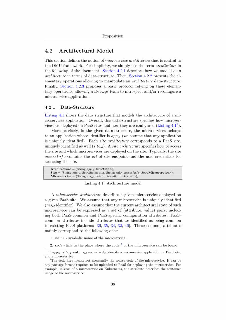
Proposition
4.2 Architectural Model
This section defines the notion of microservice architecture that is central tothe DMU framework. For simplicity, we simply use the term architecture inthe following of the document. Section 4.2.1 describes how we modelise anarchitecture in terms of data-structure. Then, Section 4.2.2 presents the el-ementary operations allowing to manipulate an architecture data-structure.Finally, Section 4.2.3 proposes a basic protocol relying on these elemen-tary operations, allowing a DevOps team to introspect and/or reconfigure amicroservice application.
4.2.1 Data-Structure
Listing 4.1 shows the data structure that models the architecture of a mi-croservices application. Overall, this data-structure specifies how microser-vices are deployed on PaaS sites and how they are configured (Listing 4.11).
More precisely, in the given data-structure, the microservices belongsto an application whose identifier is appid (we assume that any applicationis uniquely identified). Each site architecture corresponds to a PaaS site,uniquely identified as well (siteid). A site architecture specifies how to accessthe site and which microservices are deployed on the site. Typically, the siteaccessInfo contains the url of site endpoint and the user credentials foraccessing the site.
Architecture = (String appid, Set<Site>);Site = (String siteid, Set<String attr, String val> accessInfo, Set<Microservice>);Microservice = (String msid, Set<String attr, String val>);
Listing 4.1: Architecture model
A microservice architecture describes a given microservice deployed ona given PaaS site. We assume that any microservice is uniquely identified(msid identifier). We also assume that the current architectural state of suchmicroservice can be expressed as a set of (attribute, value) pairs, includ-ing both PaaS-common and PaaS-specific configuration attributes. PaaS-common attributes include attributes that we identified as being commonto existing PaaS platforms [36, 35, 34, 32, 40]. These common attributesmainly correspond to the following ones:
1. name - symbolic name of the microservice.
2. code - link to the place where the code 2 of the microservice can be found.1 appid, siteid and msid respectively identify a microservice application, a PaaS site,
and a microservice.2The code here means not necessarily the source code of the microservice. It can be
any package format required to be uploaded to PaaS for deploying the microservice. Forexample, in case of a microservice on Kubernetes, the attribute describes the containerimage of the microservice.
38

Proposition
3. state - lifecycle state for the microservice:
• CREAT ED: the microservice is created.• RUNNING: the microservice is running.• F AILED: the microservice is failed.
4. nbInstances - number of instances of the microservice.
Figure 4.2 illustrates an application architecture composed of two mi-croservices (m1 and m2) deployed both on two heterogeneous sites (site1and site2) and a third microservice m3 only deployed on site2. Notice thatthe architecture of the microservice m1 is different across different sites (e.g.,site1 and site2) in terms of the attribute value (e.g., the value of instances)and the attributes definition (e.g., memory on site2).
name: m1code: https://github.com/usr/m1.gitinstances: 5state: RUNNING
name: m2code: https://github.com/usr/m2.gitinstances: 3state: RUNNING
site1
name: m1code: https://github.com/usr/m1.gitinstances: 3state: RUNNINGmemory:512M
name: m2code: https://github.com/usr/m2.gitinstances: 2state: RUNNINGmemory:512M
name: m3code: https://github.com/usr/m3.gitinstances: 9state: RUNNINGmemory:1G
site2
Architecture
Figure 4.2: An example of microservices architecture
As previously said, the set of key-value pairs describing a microservice isextensible. Especially, each PaaS solution can extend pre-defined attributeswith additional ones in the model. For example, only the PaaS solutionof site2 in the example requires the attribute memory which specifies thememory quota of each microservice instance, while site1 does not requirethis information.
A last important point to precise regarding the data-structure modelinga microservice is that this data-structure is used both to portray the currentand the target architectures of a microservice.
4.2.2 Elementary Operations
To manipulate microservices, the DMU framework relies on the operationsprovided by PaaS sites (through their API and/or CLI). Although different
39

Proposition
PaaS platforms provide syntactically different operations, they mostly sharea common semantics. We abstract this semantics through a set of canonicalPaaSOperations allowing to manipulate a microservice architecture. Follow-ing a CRUD (Create, Read, Update, Delete) approach [71], this canonical(Listing 4.2) allows to add, get, modify and remove microservices .
Specifically, the canonical operations behave as follows:
• get: returns the architecture of the microservices currently deployedon the given PaaS site and associated to the application appid.
• add: deploys a new microservice for the account of the applicationappid.
• remove: deletes an existing microservice for the account of the appli-cation appid.
• modify: evolves the attributes of a microservice deployed for the ac-count of the application appid. This operation takes as input the cur-rent and target attributes of the microservice to modify.
For each PaaS platform managed by the DMU framework, the PaaS-specific implementation of this canonical interface (called PaaS connector)should be defined. Currently, we provide the implementations of the PaaSconnector for the Cloud Foundry, Heroku, and Kubernetes PaaS platformsin the open-source prototype of the DMU framework [72]. As an illustration,we explain here the implementation of Kubernetes and Cloud Foundry PaaSconnectors.
Regarding the PaaS Kubernetes, the PaaSconnector interface is in factdirectly mapped on Kubernetes configuration commands: create, delete, re-place and get, such commands being based on a CRUD approach as ourcanonical interface.
Regarding the PaaS Cloud Foundry, it is a bit less direct. For the canon-ical operations get, add, and remove, Cloud Foundry provides correspond-ing operations. The operation modify is a bit more complex to implement
interface PaaSOperations{Set<Microservice> get(String appid);int add(String appid, Microservice m);int remove(String appid, Microservice m);int modify(String appid, Microservice m, Microservice mnext); a
}
Listing 4.2: Architecture manipulation (PaaSOperation interface)
aTo ensure m and mnext describe the same microservice, m.id is enforced to be equalto mnext.id at the beginning of the function.
40

Proposition
because Cloud Foundry provides distinct operations to update specific at-tribute(s). Therefore, depending on the change to apply on the microservice,the operation modify requires different Cloud Foundry operations work-flows. The following pseudo-code (Listing 4.3) shows the implementationof the modify operation. By comparing the attributes’ value between thecurrent (m) and desired (mnext) microservice architecture, it determines thesequence of Cloud Foundry operations to process.
CloudFoundryConnector.modify(m, mnext) {Workflow modifyWF = new SerialWorkflow();IF (dif(m, mnext, code)):
modifyWF.addStep(uploadCode(m.id, mnext.code));m.code = mnext.code;m.state = UP LOADED;
boolean needRecompile = false;IF (dif(m, mnext, env)):
modifyWF.addStep(updateEnv(m, mnext));m.env = mnext.env;
IF (dif(m, mnext, services)):modifyWF.addStep(updateServices(m, mnext));m.services = mnext.services;
IF (needRecompile AND isCompiled(m)):modifyWF.addStep(recompile(m));m.state = ST AGING;
Set<Route> addedRoutes = mnext.routes \ m.routes;IF (addedRoutes NOT EMPTY):
modifyWF.addStep(addRoutes(addedRoutes));m.routes = m.routes ∪ addedRoutes;
Set<Route> removedRoutes = m.routes \ mnext.routes;IF (removedRoutes NOT EMPTY):
modifyWF.addStep(removeRoutes(removedRoutes));m.routes = m.routes \ removedRoutes;
IF (dif(m, mnext, nbInstances)):modifyWF.addStep(scaleNbInstances(m, mnext));m.nbInstances = mnext.nbInstances;
IF (dif(m, mnext, state)):modifyWF.addStep(updateStateAutomaton(m, mnext));m.state = mnext.state;
return modifyWF;}
Listing 4.3: CloudFoundry modify operation
4.2.3 Introspection and Reconfiguration of a MicroserviceApplication
Relying on the PaaSOperations interface, the DMU framework defines twomain introspection and reconfiguration functions:
• introspect(appid, List < Site >): retrieve the current architecture ofa given microservice application deployed on the given PaaS sites.
• reconfigure(appid, arch): reconfigure a given microservice applicationtowards the given architecture (arch). This reconfigure function is
41

Proposition
strategy-unaware, meaning that it reconfigures the application towardsthe given architecture arch through the most direct path, withouttrying to protect any SLA properties.
The function introspect is implemented as shown in Listing 4.4. It re-trieves the currently existing microservices on each site by calling the getfunction of the PaaSOperations interface.
introspect(appid, List<Site> sites) {// create an empty architecture modelArchitecture Acurrent = new Architecture();// get the microservices on each sitefor (PaaSSiteAccess site : sites) {
// get the PaaSOperation implementation class based on the type of sitePaaSOperations op = Class.forName(site.type).newInstance(site);// retrieve the microservices currently managed by a siteList<Microservice> microservices = op.get(appid);Acurrent.add(site, microservices);
}return Acurrent;
}
Listing 4.4: Core introspect protocol
The function reconfigure is defined as shown in Listing 4.5 3. For eachsite, the reconfigure function firstly computes an architectural diff [54]between the target and current architecture, determining the set of mi-croservices to reconfigure (i.e. added, removed, or modified). For each mi-croservice to reconfigure, the corresponding canonical operation (from theinterface PaaSOperation) is added to a per-site workflow. These workflowsare finally processed, on all sites in parallel.
Any canonical operation that is processed on a given PaaS site is trans-lated into its PaaS-specific version. For instance, let’s consider the usecaseillustrated by(Figure 4.3). To upgrade the microservice m to the next codeversion (modeled as m′) deployed on two PaaS sites Sa (Cloud Foundry)and Sb (Heroku), the reconfigure function behaves as follows:
• First, for the site Sa, it compares the microservices on Sa in the modelof the target architecture (i.e., m′) and the current architecture (i.e.,m); it finds that changeSet contains only a modified microservice.
• Since changeSet does not contain any added or removed microservices,it only adds the operation CloudFoundry.modify(m, m′).
• The previous steps are executed similarly for Sb, adding the operationHeroku.modify(m, m′).
3Notice that, when processing a get operation, the concerned PaaS may be processinganother operation. For consistency purposes, a PaaS connector implementation shouldensure to get a stable snapshot of the microservice architecture (i.e., wait for in-processingoperations to finish).
42

Proposition
reconfigure(Architecture Acurrent, Architecture Atarget) {// create an empty parallel workflow to store the reconfiguration workflowWorkflow reconfigure = new ParallelWorkflow();// get the reconfiguration workflow for each sitefor (PaaSSiteAccess site : desiredArchitecture.listPaaSSites()) {
// create an empty parallel workflow to store the workflow for reconfiguring the siteWorkflow reconfigSite = new ParallelWorkflow();// compare the microservices on the site in current and target architectureChangeSet changeSet = diff(Acurrent[site], Atarget[site]);// get the PaaSOperation implementation class based on the type of sitePaaSOperations op = Class.forName(site.type).newInstance(site);// call the add operation for all added microservicesfor (Microservice addedMs : changeSet.addedMs()) {
reconfigSite.addStep(op.add(addedMs));}// call the remove operation for all removed microservicesfor (Microservice removedMs : changeSet.removedMs()) {
reconfigSite.addStep(op.remove(removedMs));}// call the modify operation for all modified microservicesfor (Entry<Microservice, Microservice> modifiedMs : changeSet.modifiedMs()) {
reconfigSite.addStep(op.modify(modifiedMs.getKey(), modifiedMs.getValue()));}// add the site reconfiguration workflow to the entire reconfiguration workflowreconfigure.addStep(reconfigSite);
}// execute the reconfiguration workflowreconfigure.exec();
}
Listing 4.5: Core reconfigure protocol
• These two operations are added to the workflow reconfigure.
• During the execution of the workflow, the CloudFloundry and Herokuconnectors respectively invoke the sequence of PaaS specific operationscorresponding to the modify operation.
• Finally, the reconfigure function waits for the result of these PaaSoperations and returns.
Thus, so far, the DMU framework provides an introspect and a reconfig-ure operations. One can ask why updating a microservice application is notjust reconfiguring the application towards a desired target architectures, asshown in Listing 4.6. We call such update as a strategy-less update (shownin Figure 4.4). The reply is the following: reconfiguring a microservice appli-cation relies on processing add, remove and modify canonical operations onthe concerned microservices. Regarding the modify operation that allows tochange the configuration of a running microservice m, most PaaS, includingCloud Foundry and Heroku, imply to follow the following three main steps:
• (1) stopping m (m should indeed be stopped before updating its code),
• (2) uploading the code of m′,
43

Proposition
name: mcode: v1.zip
m
sitea(CloudFoundry)
name: mcode: v1.zip
m
siteb(Heroku)
Current Architecture
name: mcode: v2.zip
m′
sitea(CloudFoundry)
name: mcode: v2.zip
m′
siteb(Heroku)
Target Architecture
reconfigure
Figure 4.3: An example reconfigure for upgrading microservice code
• (3) starting m′.
Such processing, taking several minutes in average (because of the codedownloading), introduces a significant downtime for the updated microser-vice m. To upgrade m toward m′ without downtime, the proposed wayconsists in using strategies (presented in section Section 4.3).
push(Architecture Atarget) {// retriving current architecture of the app appid
Architecture Acurrent = introspect(Atarget.appid, Atarget.sites);// updating the app appid towards Atargetreconfigure(Acurrent, Atarget);
}
Listing 4.6: Strategy-less update protocol
reconfigureAC
target architecturecurrent architecture
At
strategy-less update
Figure 4.4: The Overview of Strategy-less Update (architecture-based)
44

Proposition
4.3 Strategy-driven Updates
This section presents how the DMU framework takes into account the needto protect SLA properties when performing an update, through the conceptof strategy. It is organized as follows. First, Section 4.3.1 introduces theprinciples of ”strategy-driven” updates. Then, Section 4.3.2 presents theimplementation of an update protocol taking into account strategies.
4.3.1 Update Process Overview
A strategy aims at allowing to update microservice applications while pro-tecting their SLA properties throughout the update process, as illustratedin Figure 4.5.
AC
...
intermediate architectures
target architecturecurrent architecture
strategy-driven update A
1A
2A
n
At
strategy-less update
Figure 4.5: Update Process Overview
To this end, a strategy determines a path of intermediate architecturesthat will be followed to reach the target architecture while protecting someSLA properties (e.g., availability, performances, resource usage). Let’s con-sider that the strategy computes a path I0, I1, .., In of intermediate archi-tectures, the last intermediate architecture In matching the target archi-tecture. The DMU framework will then reconfigure the microservices in nsteps, reaching the next intermediate architecture at each step.
In order to give a concrete example of a strategy-driven update process,let’s consider a previously mentioned update case consisting of migratingsome microservices from a PaaS site to another. Figure 4.6 shows the differ-ent paths of intermediate architectures corresponding to various strategiesthat can be used to process such update. In this figure, large boxes showPaaS sites (named site1 and site2), and the microservices deployed on them.
• Using a RemoveAdd strategy (Figure 4.6a): This strategy minimizesresource consumption. The microservices are firstly removed to getto the intermediate architecture A1, then deployed on the new site toarrive at the target architecture.
• Using a AddRemove strategy (Figure 4.6b): This strategy favors ser-vice availability. Until the microservices arrives at the architecture A′1
45

Proposition
��
��
�����
������
����� �����
�� ����
��
��
����������
��
�����
(a) remove then create (favor frugality)
��
��
�����
������
����� �����
�� ����
��
��
�����
��
��
�����
���
��
��
�����
(b) create then remove (favor availability)
��
��
�����
������
����� �����
�� ����
��
��
�����
(c) create and remove in parallel (favor speed)
Figure 4.6: The example of migrating microservices m1 and m2 from site1to site2 with three strategies
where the microservices are co-running on both two sites, they are notremoved from the old site.
• Using a Straight strategy (Figure 4.6c): Besides the two presentedstrategies, if the DevOps team prefers to finish the migration as soon aspossible, and cares less about the consumed resource and the imposeddowntime during the update, it can choose a Straight strategy todeploy microservices on the new site while removing them on the oldsite in parallel.
Notice that the DMU framework allows to launch an update process in apreview mode, simulating an update without applying it to the real system.The preview mode can help the DevOps team to decide between differentstrategies. The strategy programmer can also use the preview mode todebug and test the strategy.
4.3.2 Strategy-driven Update Protocol
With the previously presented introspect and reconfigure functions, theDMU framework evolves a given application toward a given target in themost direct way, without going through intermediate architectures. In other
46

Proposition
words, with only introspect and reconfigure functions, only strategy-lessupdates can be processed by the DMU framework.
Taking into account strategies goes through providing a dedicated con-cept allowing to define them. Concretely, we modelize a strategy as a pro-grammable unit providing one main feature: computing the next interme-diate architecture to reach in order to update a microservice applicationtowards a given target. As we place our framework in an object-orientedenvironment, a strategy is naturally mapped on a class defining a nextmethod:
• Strategy.next(Acurrent, Atarget): computes the next intermediate ar-chitecture to reach based on the current architecture of the application,the desired target architecture (Atarget)
To evolve from the current architecture to a desired target one –whileconforming to a given strategy–, the DMU framework invokes next and re-configure sequentially and iteratively (Listing 4.7 4). In other words, theupdate protocol is now defined as a fix-point parameterized by a strategy.At each step, the fix-point requests the strategy to compute the next ar-chitecture to reach, then reconfigures the microservices towards this nextarchitecture, and repeat these two steps until reaching the target architec-ture.
push(Architecture Atarget, Strategy strategy) {Architecture Acurrent, Anext;Acurrent = introspect(Atarget.appid, Atarget.sites);// fix-point, updating appid towards Atargetwhile (Acurrent.differ(Atarget)) {
// compute next intermediate architecture AnextAnext = next(Acurrent, Atarget, strategy);if (Anext == null) exit(”target unreachable”); ∗∗// to reach the next architecture Anextreconfigure(Acurrent, Anext);Acurrent = introspect(appid, Atarget.sites);
}}
Listing 4.7: Strategy-driven update protocol (fix-point)
There is one main reason why the update protocol is defined as a fix-point instead of calculating the whole sequence of intermediate architecturesat the beginning. This reason is to allow the DevOps team to modify thestrategy and/or the target architecture at each step. This feature may beespecially useful when considering failures occurring at update time (seeSection 4.5).
Similarly to the update protocol, the preview protocol (Listing 4.8) alsoinvokes the next function iteratively for computing the next architecture for
4The line tagged with ** represents an error case that is discussed in Section 4.4.1.
47

Proposition
arriving at the final architecture Atarget. However, the preview protocol ac-cumulates the sequence of architectures (archSequence) instead of invokingthe reconfigure function, so that effective microservices are not impacted.The returned archSequence allows to visualize the path of intermediatearchitectures that will be followed when processing the update.List<Architecture> preview(Architecture Ainitial, Architecture Atarget, Strategy
strategy) {Architecture Acurrent, Anext;List<Architecture> archSequence;Acurrent = Ainitial;archSequence.add(Acurrent);// fix-point, calculating intermediate architectures towards Atargetwhile (Acurrent.differ(Atarget)) {
// compute next intermediate architecture AnextAnext = strategy.next(Acurrent, Atarget);if (Anext == null) exit(”target unreachable”); ∗∗// add the Anext into the sequence of architecturesarchSequence.add(Anext);Acurrent = Anext;
}return archSequence;
}
Listing 4.8: Strategy preview protocol
Regarding the termination, the update fix-point (Listing 4.7) stops eitherwhen the target architecture has been reached, or when the strategy hasno more changes to process. In case the target has not been reached 5,the DevOps team may simply restart an update with an adapted strategyand/or target architecture (explained in Section 4.5).
In the case where a strategy is badly programmed, especially when transi-tions generate opposite changes on the architecture, the fix-point may neverterminate. To manage such case, the DevOps team can pre-check the ter-mination of an update by using the preview mode.
5This case corresponds to the line tagged with ** in Listing 4.7.
48

Proposition
4.4 Strategy Programming
Section 4.4.1 presents the programming model allowing to program strate-gies. We used this programming model to provide a set of predefined strate-gies with the proposed DMU framework, some of these strategies beingpresented in this chapter as a didactic case. In particular, Section 4.4.2 illus-trates the strategy programming model through the well-known BlueGreenstrategy.
4.4.1 Strategy Design
A strategy provides one main feature: computing the next architecture toreach according to the current and target architectures.
To achieve this, the DMU framework naturally models a strategy as anordered list of transition elements (described in Listing 4.9). A transitionmanages an elementary update that may participate in an overall updateprocess. To compute the next intermediate architecture, a strategy processesits transitions incrementally, until finding one having changes to apply onthe current architecture.
abstract class Strategy {// List of transitions (to define in subclasses)List<Transition> transitions = new List();
// compute the next intermediate architecture to reachArchitecture next(Architecture Acurrent, Architecture Atarget) {
// process transitions until finding one having changes// to perform on the current architecturefor each Transition tr in transitions {
Architecture Anext = tr.process(Acurrent, Atarget);if (Anext != null) return Anext;
}return null;
}}
interface Transition {// deliver a (not null) next architecture if the transition has changes to processArchitecture process(Architecture Acurrent, Architecture Atarget);
}
Listing 4.9: Strategy model
Pragmatically, a transition provides a process() method that 1) deter-mines if its elementary update is relevant to get closer (i.e., go forward)to the target and 2) delivers a next architecture in accordance. For in-stance, a transition Tadd managing the adding of microservices behaves asfollows (Listing 4.10). Comparing the current and target architectures, itfirstly determines if new microservices have to be deployed. If no, it simplyreturns null. If yes, it delivers a next architecture containing the currentmicroservices plus the new microservices to deploy. Symetrically, a transi-
49

Proposition
tion Tremove determines if there are microservices to undeploy. If yes, itdelivers an architecture containing the current microservices minus those toundeploy.
class AddRemoveStrategy extends Strategy {// manages addings and removings of microservices,// processing addings then removingstransitions = new List(Tadd, Tremove);
}
class Tadd implements Transition {Architecture process (Architecture Acurrent, Architecture Atarget) {
// get microservices added in Atarget compared to AcurrentList<Microservice> addings = Atarget.minus(Acurrent);if (addings != null) {
// return an architecture including current microservices plus the ones to addArchitecture Anext = Acurrent.clone();Anext.add(addings);return Anext;
} else return null;}
}
class Tremove implements Transition {Architecture process (Architecture Acurrent, Architecture Atarget) {
// get microservices removed in Atarget compared to AcurrentList<Microservice> removings = Acurrent.minus(Atarget);if (removings != null) {// return an architecture including current microservices minus the ones to remove
Architecture Anext = Acurrent.clone();Anext.remove(removings);return Anext;
} else return null;}
}
Listing 4.10: Implementation of the example strategy AddRemove and itstransitions
Figure 4.7 illustrates using the AddRemoveStrategy (Listing 4.10) toupdate an elementary application composed of two microservices (M1, M2)deployed on a site Sa. The target architecture only contains the microserviceM3 on Sb.
current architecture
M2
Site Sa
M1 transitionTadd
intermediate architecture
M2
M1 M3
Site Sb Site Sa Site Sb
target architecture
M3
Site Sa Site Sb
transitionTremove
Figure 4.7: Update case with AddRemove strategy
• At the first step, the update fix-point processes the first transition(Tadd) of the strategy, that delivers the intermediate architecture (A)
50

Proposition
composed of the current microservices plus M3 deployed on Sb. Theapplication is then reconfigured towards this intermediate architectureA.
• At the second step, the fix-point processes again the transition Tadd,that has no more changes to perform. It then processes the next tran-sition (Tremove), that removes microservices not appearing in thetarget architecture (M1 and M2 on Sa). The application is then recon-figured towards this architecture and the fix-point terminates becausethe target has been reached.
Notice that one can define different strategies by changing the order oftransitions. In the previous update case, the reverse sequence of transitions(i.e., (Tremove, Tadd) instead of (Tadd, Tremove)) would generate a dif-ferent path of intermediate architectures, removing M1 and M2 first, thenadding M3.
Notice also that transitions may apply changes over several steps of thefix-point. Let’s consider a transition scaling up microservices horizontally(i.e., growing their number of instances) as follow. For each microserviceto scale, new instances should be deployed and started one by one 6. Eachtime it is processed, this transition returns a next architecture in whichevery microservice to scale has one more instance. When all microservicesreach their target number of instances, it simply returns null.
4.4.2 Didactic case: the BlueGreen Strategy
As a representative case, we explain how to program the BlueGreen strategythat updates an application without downtime – through installing, startingand testing the new version (the green one) before uninstalling the currentversion (the blue one). Once the green environment is ready, incomingrequests should be routed to it.
We define such strategy through a simple sequence composed of fourtransitions (Listing 4.11).
class BlueGreen implements Strategy {List<Transition> = new List(Tadd, Tupdate, Tswitch, Tremove);
}
Listing 4.11: BlueGreen Strategy
These transitions perform the following changes.
• Tadd: deploys microservices defined in the target architecture butundefined in the current architecture.
6This pattern is required for microservices that do not support having several instancesstarted concurrently.
51

Proposition
• Tupdate: deploys the green version of the microservices that are up-dated in the target architecture (associating them to a temporary route(url) for testing purposes).
• Tswitch: switches from temporary route to regular route for greenmicroservices deployed at the previous step.
• Tremove: removes microservices entities that are undefined in thetarget architecture but defined in the current architecture.
The implementation of the transitions Tadd and Tremove are quite sim-ilar to the code given in Listing 4.10. We show hereafter the code of thetransitions Tupdate (Listing 4.12) and Tswitch (Listing 4.13).
class Tupdate implements Transition {Architecture process(Acurrent, Atarget) {
Architecture Anext;// get microservices updated in At compared to AcList<Microservice> updates = Ac.updated(At);if (updates != null) {
Anext = Ac.clone();for each Microservice m in updates {
// deploy green version for the microservice to updateMicroservice mgreen = m.clone();mgreen.set(”route”, mt.get(”temporary−route”));mgreen.set(”role”, ”green”);Anext.add(mgreen);
}}return Anext;
} // end of process method}
Listing 4.12: Implementation of the transition Tupdate
class Tswitch implements Transition {Architecture process(Acurrent, Atarget) {
Architecture Anext;// get green versions of microservices in current architectureList<Microservice> greens = Ac.greens();if (greens != null) {
Anext = Ac.clone();for each Microservice m in greens {
// assign the regular route to green versions of microservicesm.set(”route”, m.get(”regular−route”));m.set(”role”, ”blue”);
}}return Anext;
} // end of process method}
Listing 4.13: Implementation of the transition Tswitch
To illustrate how the DMU framework process an update with the imple-mented BlueGreen strategy, let’s consider the case described in Figure 4.8.
52

Proposition
To upgrade M1 towards M ′1 and remove M3, the DevOps team makes the
following request to the DMU framework: push(At, BlueGreen).
initial architecture architecture 2 target architecture
Legend :
added microservices,associated to temporary route
M2(x,1)
Sa Sb
M2(x,2)
M1'(r,2)
M1'(r,2)
M2(x,1)
Sa Sb
M1' (r, 2)
M3(y,1)
step 3M2(x,2)
M1' (r, 2)
architecture 1
M2(x,1)
Sa Sb
M1'(t,2)
M3(y,1)
M1(r,2)
M2(x,2)
M1'(t,2)
M1(r,2)
M2(x,1)
Sa Sb
M3(y,1)
M1(r,2)
M2(x,2)
M1(r,2)
removedmicroservices
route changedto regular one
step 1 step 2
Highlight a change compared to precedent architecture M(x,y)M(x,y)
The microservice M is deployed, it is associated to the route x and it has y instances running
M1(r,2) M1(r,2)
Figure 4.8: Processing the transitions of the BlueGreen strategy
The DMU framework starts by getting the current architecture (let’s callit Ac) for the application A and enters the update fix-point. It processes thefirst transition Tadd, that has no changes to perform as At does not includeadditional microservices compared to Ac. It then processes the second tran-sition (Tupdate) that delivers the architecture 1 shown in Figure 4.8. In thisarchitecture, M1 is deployed both in its current version of code and in itsnew (green) version (M ′
1). Then, the framework reconfigures the applicationtowards architecture 1 by calling the add operation of the two sites (SaandSb) in parallel. Notice that external client requests continue to be routed toM1 so far, as M ′
1 is assigned a temporary route.At the second step of the fix-point, transitions are processed again. The
first and second transitions have no more changes to perform. The thirdtransition (Tswitch) computes the architecture 2 where M ′
1 is now associatedto the regular route, and the old version of M1 has been removed. Thereconfigure protocol calls the modify operation (changing the route of M ′
1)on the two sites to deliver architecture 2.
Once the application is reconfigured towards architecture 2, the frame-work restarts processing the transitions. Only the last transition (Tremove)has some changes to process, producing the architecture 3. The reconfigureprotocol calls the remove operation for M1 and M3 in parallel to deliver ar-chitecture 3. Finally, the architecture 3 matches the target, leading to thecompletion of the update fix-point.
53

Proposition
4.5 Update Robustness
In this section, we consider faults occurring during an update process. Sec-tion 4.5.1 presents the core principles underlying the management of suchfaults. Section 4.5.2 details various types of faults that may impact an up-date and how to handle such faults. Finally, Section 4.5.3 summarizes howthe DMU framework helps the DevOps team to handle each type of faults.
4.5.1 Core principles
Automating the update of microservice applications requires to considerthe faults that may occur during an update. Before explaining how weaddress faults, let’s recall that nowadays, there are millions of DevOps teamsthat (manually) perform daily updates of their microservice applications,through the Command Line Interface provided by PaaS sites. To processsuch updates, DevOps teams send several commands to one or more PaaSsites, each command being entirely processed on a PaaS site before the nextcommand is sent.
During such manual update processes, faults may occur: a microservicemay fail to process some command, a PaaS site may crash, the networkconnecting a PaaS site to the host used by the DevOps team may face somedisconnection. However, PaaS sites follow a fail-stop failure model [73] thatenforces the consistency of the microservices they host. This means thatonce a PaaS site is up and reachable, the microservices it hosts can beintrospected and reconfigured. Thus, if a PaaS site crashes during an update,it should be relaunched, but once this is done, the DevOps team can alwaysissue the necessary CLI commands to pursue the update.
Going back to our framework, we do not provide a better level of robust-ness regarding faults, we just rely on the consistency property ensured byPaaS sites. In other words, as with PaaS sites, when using our framework,DevOps teams have the guarantee that their microservice applications stayconsistent, thereby manageable. Nevertheless, if we do not provide a betterlevel of robustness, the fact that we automatize updates allows to simplifythe work of the DevOps team in the presence of faults. We will explain howthis is achieved in the next sections.
Going one step further, it is important to understand that the consis-tency property provided by PaaS sites allows to leverage a kill-restartcapability at the level of our framework. Indeed, whatever the momentwhen an update is interrupted, either due to a fault or due to a voluntarilyinterruption from the DevOps team, a new update process can always bestarted. Overall, the kill-restart capability relies on the following three mainproperties.
• PaaS consistency. Whatever the current architectural state for a mi-croservice application, it is a regular state for the PaaS sites hosting
54

Proposition
it, meaning that microservices can always be introspected and/or re-configured.
• Stateless framework. The DMU framework does not keep anymodel@runtime for the managed microservices, a data-structure thatis especially difficult to maintain in the presence of faults. The rea-son for the difficulty is that the data should stay consistent with theeffective microservices architectures. Instead, the DMU frameworkdynamically gets the current architecture of microservices to update,using introspection capabilities provided by PaaS sites.
• Update idempotence. Following an architecture-based approach, tran-sitions compare the current and target architectures to determine thechanges to perform. Once a change has been applied, the DMU frame-work does not redo it again. Thus, restarting an update that waspreviously issued does not cause side effects.
Notice that in any case, the DevOps team is free to either pursue afailed update update towards the initial target through the initial strategy,or change the target and/or the strategy. Changing the target architectureoffers a way to fix some microservice configuration. It also offers a way toroll-back an entire update, by defining the new target architecture as theinitial architecture that the microservices had when launching the update.Figure 4.9 illustrates an update that fails, the DevOps team deciding topursue the update with a new strategy S′ and a new target architecture At′.
Strategy S
Ac Ai Ak At...
Strategy S'
Ac' Av At'...
(1) push(At, S)
Ti Tj Tk Tl
Tu Tv Tw
(2) push(At', S')
Figure 4.9: Management of failures at update time by adapting the strategyand the target
Upon a failure, the DevOps team may intend to pursue the previouslyinterrupted update towards the given target. To this end, it may just re-issue the initial push command if the used strategy is versatile (Figure 4.10a).We consider a strategy as versatile if it does not make assumptions on theinitial architecture of the microservice application to update. That is, the
55

Proposition
strategy accepts any architecture as the initial architecture of the update.A typical versatile strategy is the Straight one, that updates a microserviceapplication towards a given target through the most direct path, withoutgoing through intermediate architectures.
Let’s consider a fault occurring during the transition between the archi-tecture Ai and the architecture Ai+1. If the used strategy is not versatile,the DevOps team may then issue a push command with the Straight strat-egy (a versatile one) and the next architecture (Ai+1) given as target (Fig-ure 4.10b). 7 Once done, the DevOps team may then re-issue the initialpush command, with the initial strategy and the initial target architecturegiven as input.
����������
� � �
�������������
�� �� �� ��
� �������������������
���
�������������
����������
� � �
�������������
�� �� �� ��
� �����������
���
�����������������������������������
���������������������������������������
Figure 4.10: Management of failures at update time by pursuing the inter-rupted update
4.5.2 Identification of faults
Before classifying the faults that may occur during the update, we recallhere the overview of the DMU framework (Figure 4.11). Three actors areinvolved during the update: the DevOps team, the DMU framework, and thePaaS sites. During the update, the DMU framework translates the DevOpsteam’s commands into the operations sending to the PaaS sites which hostthe microservices.
Based on this operational architecture, and following the literature on7This next architecture can be retrieved from the DMU framework execution log.
56

Proposition
DevOps team
DMU Framework
Frameworkcore
PaaS connectors
strategies
PaaS sites
Figure 4.11: The operational architecture of the DMU Framework
faults [74], the faults to consider can be classified into three non-exclusivegroups 8:
• development faults: we consider here the software faults introducedduring the development of the DMU framework (such as null deref-erences), leading to either an interruption or an exception raising atexecution time.
• physical faults: we consider here the faults originated in hardware (in-cluding the framework servers, the PaaS servers and network devices),such as electric power outage or hardware damage.
• interaction faults: we consider here the faults originated outside theDMU framework, including the user mistakes (e.g., an erroneous input)and faults propagated from the external components which interactwith the DMU framework (e.g., a PaaS site failure).
All these kinds of faults force an update to be interrupted. When anupdate is interrupted due to faults, the following steps are required to recoverthe faults:
1. identify the fault origin
2. fix the faulty components (hardware and software)
3. repair the failed update to evolve the microservices architecture to thetarget
Development faults
This section discusses the development faults of the DMU framework. TheDMU framework implementation contains three parts: the framework core,
8 According to the literature [74], the faults can be classified from eight criteria. In allthe 256 combined fault classes, there are 31 likely combinations. All these combined faultsbelong to three overlapping groups: development faults, physical faults, and interactionfaults.
57

Proposition
the PaaS connectors, and the strategies implementation. The frameworkcore is made of code that is stable, thus we consider that this code can bechecked and verified. The PaaS connectors evolve with the PaaS API, whichis also usually stable (i.e., backward-compatible). Thus, we believe that it isreasonable to assume a bug-free implementation of the framework core andthe PaaS connectors.
As the part most probably to be customized by the DevOps team, thestrategy implementation is not fully trusted. The following part of thesection focuses on presenting how the DMU framework helps to handle thesoftware faults in the strategy implementation.
During the development of a strategy, the strategy programmer cantake advantage of the preview mode (Listing 4.8) provided by the DMUframework to test the correctness of the strategy. The preview mode cantake mock inputs (i.e., initial and target architectures) to calculate the out-put (i.e., a sequence of intermediate architectures) produced by a strategy.Therefore, the strategy programmer can test the strategy by simply speci-fying the expected intermediate architectures for each typical case of initialand target architectures. The more inputs covered in the test, the fewerbugs hidden in the delivered strategy.
During the execution, the DMU framework handles an update requestby iteratively calculating and applying the next intermediate architecturesuntil reaching the target (Listing 4.7) as presented in Section 4.3.2. At eachstep, the strategy is in charge of producing the expected next architecture.A badly programmed strategy will either :
• raise an exception because it performs a bad action (e.g., null pointerexception) or lead to an interruption of the running update process(e.g., division by zero). In this case, the ongoing update is automati-cally stopped.
• produce an incorrect intermediate architecture, that cannot be appliedby PaaS sites (e.g., the architecture contains two microservices withduplicate id). This invalid architecture is automatically detected byPaaS sites while applying the architecture.
• produce an endless sequence of intermediate architectures. This casemay be automatically detected by the framework by processing thepreview protocol (Listing 4.8) at the beginning of each update request.Moreover, an update request will be automatically stopped if it lastsmore than a given delay, if such delay is given by the DevOps team 9.In addition, the maximum number of intermediate architectures canalso be given.
9The timeout value is configurable for each update request.
58

Proposition
When a strategy is identified as having an erroneous behavior while pro-cessing a given update, the update is automatically stopped and, thanks tothe kill-restart capability, the DevOps team is invited to restart the updatewith an adapted strategy and/or target architecture.
In summary, during the development, the preview mode of the DMUframework facilitates the debug of the strategy implementation. During theexecution, the DMU framework also helps to detect the software flaws ofstrategies by catching the exceptions and pre-checking whether the speci-fied target is attainable for the strategy. The framework follows a fail-fastprinciple [75] once detected any faults. That is, the framework stops theexecution as soon as any unexpected error occurs. A stopped update canthen be pursued through the kill-restart capability of the DMU framework.
Physical faults
This section discusses the physical faults during the update in terms oftheir types, their detection, and their repair. Physical faults encompassfaults that can occur at any hardware involved in the update: the PaaSinfrastructure, the DMU framework infrastructure, and the networkconnecting the framework to the PaaS sites. Based on the location of thefaults with respect to the system boundary, such faults can be classifiedinto two groups: external faults and internal faults (Figure 4.12). Externalfaults originates outside of the framework (i.e., at PaaS sites or at thenetwork connecting the framework to the PaaS sites). Internal faults ariseinside the underlying infrastructure of the DMU framework.
Framework
external systemsinternal system
network
PaaS site A
PaaS site B
PaaS site C
Figure 4.12: The classification of physical faults based on the location
To deal with physical faults, the DMU framework should firstly detectthem. As previously said, PaaS sites are assumed to follow a fail-stop failuremodel [73], where any fault occurring at a PaaS site P leads to automaticallystopping PS while ensuring the consistency of the micro-services P manages.
59

Proposition
At the level of the framework, PaaS site faults are detected through usingtimeouts when issuing PaaS commands. Network faults are also detectedthrough timeouts.
Regarding internal faults, we assume as well that the DMU frameworkfollows a fail-stop failure model. Therefore, internal faults obviously causethe framework execution to be interrupted.
To recover from such faults when they occur at update time, the DevOpsteam needs to relaunch and continue the update process, relying again onthe kill-restart capability of the DMU framework.
Interaction faults
Interaction faults are faults which occur at the elements interacting with theDMU framework during the update. As shown in Figure 4.13, an updateprocess involves three actors: the DevOps team, the DMU framework, andthe PaaS sites. The DevOps team issues the update command to the DMUframework. The DMU framework translates the update command into asequence of PaaS operations. The PaaS sites apply the PaaS operationsrequested by the DMU framework. The interaction faults include the failuresof the external systems (i.e., PaaS sites) and the mistakes of the user (i.e.the DevOps team).
Figure 4.13: Involved software components in an update command
The failures of PaaS sites caused by hardware faults (i.e., external phys-ical faults) have already been discussed in Section 4.5.2. The user mistakesare the operational mistakes conducted by the DevOps team during the up-date. These mistakes include the harmful human actions and the erroneousinputs.
• Harmful human actions are the DevOps team’s actions which causethe update to be interrupted before reaching the target. These actionsinclude starting or stopping the update command at the wrong time.In practice, it corresponds to the scenario of concurrently updating amicroservice or accidentally stopping an ongoing update process.Notice that the detection of concurrent updates is not under the chargeof the DMU framework. In practice, each microservice is managed bya specific DevOps team, which has its proper operator in charge ofupdating the microservice. Therefore, the organization and the op-erational disciplines of microservices can avoid the concurrent access.Regarding the harmful action of stopping an unfinished update, it does
60

Proposition
not require the extra detection, as the framework execution is alreadystopped.Overall, to repair the faults caused by harmful actions, a DevOps teamsimply needs to re-issue the same update command.
• The user inputs include the target microservices architecture and thestrategy choice. Therefore, the erroneous inputs includes the followingcases: an erroneous microservices architecture, flawed microservicescodes or configurations, or a wrong strategy choice which does notdeal with the specified update.Some inputs errors can be detected at the beginning of an updatewhen processing the preview mode (e.g., an invalid target architec-ture). Others inputs errors will be detected when processing PaaS op-erations (e.g., a microservice unable to be started). Such errors leavethe microservices into an intermediate architectural state that does notcorrespond to the target architecture. In any case, the DevOps teamcan exploit the kill-restart capability to pursue the interrupted update.Then, there are two possible choices here to pursue the update process.The first choice is to roll-back to the initial microservices architecture.In this case, the DevOps team simply specifies the initial architectureas target in the new update command. For such roll-back update, thestrategy Straight is usually chosen. Otherwise, the DevOps team canchange the strategy and/or roll-forward to a new target architecture.
4.5.3 Summary
The previous analysis involves three criteria of faults: the origin based onthe system boundary (internal or external), the origin phase (developmentor operational), and the nature (hardware or software). Figure 4.14 showsthe likely combinations of fault classes. Specifically, the origin of faultscan be classified into three categories(Figure 4.15): the user (A), the DMUframework (B), and the external systems (C) 10.
All these faults eventually cause the interruption of the update 11, let-ting the updated application in an arbitrary architectural state, althoughconsistent.
The DMU framework helps the DevOps team to repair these faultsthrough its kill-restart capability. The faults at the external systems (#3,#4) and the hardware faults at the DMU framework (#2) can be repairedby re-issuing the same update command (presented in Section 4.5.2 and Sec-tion 4.5.2). Regarding the software faults at the DMU framework (#1), weconcentrate on discussing the faults in the strategy implementation, which
10We separate the user from the external system, because the faults caused by theuser-made mistakes usually requires specific repair methods (i.e. change user inputs).
11The faults detection is presented in the previous detailed analysis.
61

Proposition
Faults
development operational
internal external
software#1
hardware#2
hardware#3
software#5
Development Faults Physical Faults Interaction Faults
userexternal systems
software#4
DMU framework
operational operational
system boundary :
originating location :
originating phase :
nature :
Figure 4.14: The classes of combined faults
can be repaired by re-issuing the update command with an alternate strategy(presented in Section 4.5.2). In terms of the faults caused by user mistakes(#5), depending on the fault reason (actions or inputs), it can be repairedby resuming, rolling-back, or rolling-forward the update (presented in Sec-tion 4.5.2). It is important to notice that all these repair processes can beapplied by re-issuing another update command with the appropriate targetarchitecture.
Figure 4.15: Origins of update faults
To sum up, whichever the type of faults, after it triggers the updateto be interrupted, the DevOps team can exploit the kill-restart capabilityto repair the failed update. In the overall process of faults recovery, thefaults still need human intervention to identify the fault origin, fix the error(e.g., correct the execution environment or the update command input),and decide the repair method. Once this is done, the DevOps team justhas to relaunch the update process without questioning oneself. Due tothe idempotency property, changes that have already been processed willnot be processed again, and changes that have not yet been processed willnow be processed, unless additional faults occur in which case the same
62

Proposition
repair process will be applied again. This is how the DMU framework helpsDevOps team to manage faults.
By comparison, when DevOps teams process manual updates and face afault, they have to determine what changes have already been processed andcompute what are the additional changes that need to be processed to reachthe given target architecture. As the update of multiple microservices onmultiple PaaS sites usually contains multiple operations executed in parallel,such manual repairs are exhausting and error-prone.
63

Chapter 5
Evaluation
Contents5.1 SLA protection . . . . . . . . . . . . . . . . . . . . 65
5.1.1 Lizard application . . . . . . . . . . . . . . . . . . 655.1.2 Account application . . . . . . . . . . . . . . . . . 68
5.2 Robustness . . . . . . . . . . . . . . . . . . . . . . 705.2.1 Network faults . . . . . . . . . . . . . . . . . . . . 725.2.2 Update process faults . . . . . . . . . . . . . . . . 745.2.3 Erroneous strategy . . . . . . . . . . . . . . . . . . 755.2.4 Microservice faults . . . . . . . . . . . . . . . . . . 78
5.3 Ease of use . . . . . . . . . . . . . . . . . . . . . . 795.3.1 Programming Strategies . . . . . . . . . . . . . . . 805.3.2 Updating Microservices . . . . . . . . . . . . . . . 815.3.3 Comparison with an imperative approach . . . . . 83
This chapter evaluates the proposed DMU framework from three aspects:the SLA protection, the robustness, and the ease of use.
64

Evaluation
5.1 SLA protection
This section reports on how the DMU framework protects SLA constraintsthrough two use-cases: a production microservices application Lizard andan open-source microservices application Account.
5.1.1 Lizard application
Lizard is a cross-canal order capture application composed of four microser-vices (Shop Front, Catalog, Eligibility and Basket). Figure 5.1 shows thearchitecture of Lizard. The application is about 10000 lines programmedin Java / Angular.
Figure 5.1: The architecture of the use case Lizard
We use the DMU framework to update a complete clone of Lizard in liveproduction at Orange, focusing on the simultaneous update of two microser-vices ((C)atalog and (E)ligibility) that are deployed redundantly over threedistributed CloudFoundry PaaS sites (Sa, Sb and Sc). The update to per-form includes a code upgrade for the Catalog microservice and configurationchanges for the Eligibility microservice.
Cloud Foundry is used in version 2.75.0, running on the Cloudwattcloud [76] on top of the OpenStack IaaS [31], under VMs with medium flavor(2vCPUs, 4GB RAM, 50GB disk). The update framework is launched froma remote computer (Intel i7-7820HQ @ 2.90 GHz, 16GB RAM, 500GB SSDdisk).
Four strategies are experimented to process such update, comparing theirbehavior and impacts (in terms of time efficiency, financial cost, and mi-
65

Evaluation
croservices availability). The strategies impacts are measured with the fol-lowing metrics:
• time efficiency: the duration of the whole update process
• financial cost: the additional resource consumption (representative ofthe billing costs 1) for the update.
• microservices availability: the rate of rejected microservices requestsduring the update. During the update, we monitor the microservicesperformance under their anticipated peak load condition (10000 re-quests per minute) with Apache Jmeter.
Each experiment is repeated 30 times to get the average data. Results aregiven in Figure 5.2.
Figure 5.2: Update metrics of the Lizard application use-case
The Canary strategy (whose behavior is shown in Figure 5.3) does notinvolve an additional cost in terms of resource usage. It ensures that anydeployment of a new microservice instance is preceded by the removal of acurrent one. In the version we used, the first new instance being deployedis associated with a temporary route to allow testing before continuing theupdate. Notice that although not visible in the figure, some client requestsare not correctly served (about 0.007%), as the experiments are performedunder the peak load condition and the microservices have one less instancerunning during the update. Overall, this strategy involves 21 intermediate
1In the experiments, the resource cost is calculated by multiplying the number ofinstances by their memory size (in GB) by total duration (in minutes), as it is the billingmodel used by most Cloud Foundry services.
66

Evaluation
architectures to reach the target, 7 per site, sites being updated sequentially.Its processing took about 10 minutes.
C(r,3)
E(r,3)
current architecture
C(r,3)
E(r,3)
C(r,3)
E(r,3)
Sa Sb Sc
C(r,2)
C'(t,1)
A2
C(r,3)
E(r,3)
C(r,3)
E(r,3)E(r,2)
E'(t,1)
C(r, 2)
E(r, 2)
A1
C(r,3)
E(r,3)
C(r,3)
E(r,3)
C(r,2)
C' (r, 1)
A3
C(r,3)
E(r,3)
C(r,3)
E(r,3)E(r,2)
E' (r, 1)
C(r, 1)
C'(r,1)
A4
C(r,3)
E(r,3)
C(r,3)
E(r,3)E(r, 1)
E'(r,1)
C(r,1)
C'(r, 2)
A5
C(r,3)
E(r,3)
C(r,3)
E(r,3)E(r,1)
E'(r,2)
C'(r,2)
A6
E'(r,2)
A7
C(r,3)
E(r,3)
C(r,3)
E(r,3)
Sa Sb Sc
Sa Sb Sc
Sa Sb Sc
Sa Sb Sc Sa Sb Sc
Sa Sb Sc
E'(r, 2)
C(r,3)
E(r,3)
C(r,3)
E(r,3)E(r, 0)
C(r, 0)
C'(r, 3)
E'(r, 3)
Sa Sb Sc
...
instance-numberchanged
added microservices
route changed toregular one
Legend : Highlight a change compared to precedent architecture
M(x,y)The microservice M is deployed, it is associated to the route x and it has y instances running
Figure 5.3: Real application update through the Canary strategy
In comparison, the BlueGreen strategy (Figure 5.4) updates the twomicroservices through creating the three new (green) instances before re-moving the three current (blue) ones, on all sites in parallel. Accordingly, itensures the same availability but consumes nearly the double resource dur-ing the update. The duration is about 7 minutes, corresponding to the timerequired to create the new microservices instances (which includes uploadingtheir code), to switch their route, and remove the three blue instances, onone site. In the practice, BlueGreen strategy also brings another benefit:enabling the DevOps team to perform load tests on the new version whenarriving the first intermediate architecture A1.
������
������
�
���� �����������������
���������
�
��
������
���������
���
��
�
�
��
�
������
��������
������
���������
��
������������������
�
��
�
�������
�������
���������������� �� �������� ����������������� ����������������������
�������������������������������� ���� ������������������ ����� ������� ������������
Figure 5.4: Real application update through the BlueGreen strategy
The Mixed strategy (Figure 5.5) updates microservices instance by in-
67

Evaluation
C(r,3)
E(r,3)
Sa
current architecture C(r,3)
C'( rt,1)
Sa
A1
E(r,3)
E'( rt,1)
A2 A3 A4
SbSc
Sa
SbSc
C(r,3)
C'( r,1)
E(r,3)
E'( r,1)
Sa
SbSc
C(r, 2)
E(r, 2)
C'(r, 2)
E'(r, 2)
Sa
SbSc
C(r, 1)
E(r, 1)
C'(r, 3)
E'(r, 3)
ScSb
target architecture
Sa
SbSc
C'(r,3)
E'(r,3)
Legend : Highlight a change compared to precedent architecture M(x,y)M(x,y)
The microservice M is deployed, it is associated to the route x and it has y instances running
Figure 5.5: Real application update through the Mixed strategy
stance, creating a new instance before removing an old one, across allsites in parallel. This strategy takes approximately the same duration asBlueGreen, with no downtime. It further limits the update cost in termsof resource usage since it uses only one extra instance for each microservicewhile the BlueGreen doubles the number of instances per site. However,the DevOps team cannot load test the new version microservice with theMixed strategy.
Finally, the Straight strategy delivers the shortest update duration (4minutes), as it reaches the target without going through intermediate ar-chitectures. The duration corresponds to the time needed to update bothmicroservices on one site, the three sites being updated in parallel. Thisstrategy does not consume any additional resources but induces the largestdowntime (29.71% requests failed) as the microservices are stopped beforetheir new version is uploaded, recompiled, and restarted.
5.1.2 Account application
Another use case is an open-source microservices-based application namedAccount [77]. As shown in Figure 5.6, the application consists of two mi-croservices: web and account. The microservice web is deployed with 120instances, and account with 150 instances over three Cloud Foundry sites.We experiment through updating the code of the microservice account withvarious strategies.
During the experiments, we find that the Straight strategy and theBlueGreen strategy cannot properly update the microservice account inour experiment environment. The update either takes several hours or neversucceeds to start all the instances. The reason is that our Cloud Foundryplatforms limit the number of concurrently starting instances, as they havelimited resource. According to Cloud Foundry documentation [79], if toomany instances are starting concurrently, they are slow to start or do notstart successfully at all.
Both the Straight strategy and the BlueGreen strategy contain a step
68

Evaluation
Figure 5.6: The architecture of the use case Account. Reprinted from [78]
that concurrently start 150 instances on each site, which causes the CloudFoundry platforms failing to start all the instances within a reasonable du-ration. Therefore, this application needs to be updated with the strategyCanary or Mix, that incrementally starts the new instances. We configurethese strategies to incrementally update 20 instances each time.
Figure 5.7 shows the experiments result for the update with the strategyCanary and Mixed. As shown, these two incremental update strategy cancorrectly perform the update within 30 minutes. Similar to the experimentswith the use case Lizard, the strategy Canary consumes more resourcecomparing to the strategy Mixed at the cost of slightly reduced availability.
Figure 5.7: Update metrics of the use case Account with two strategies
69

Evaluation
5.2 Robustness
This section evaluates our DMU framework under faults. For each type offaults that may be encountered, we experiment a typical fault scenario.
The faults can originate from three locations (shown in Figure 4.15):the user, the DMU framework, or the external systems. The (end) userof the DMU framework is the DevOps team that issues update requests tomanage microservices. The DMU framework includes both the frameworksoftware and its underlying infrastructure. The external systems includethe PaaS sites involved in the update and the network connecting the DMUframework to the PaaS sites.
Table 5.1 presents the different faults, the way we triggered them in ourexperiments, and the expected handling behaviors for each type of faults.Typically, the external system faults are exemplified by the outage of thenetwork between the DMU framework and the PaaS sites. The generalhandling behavior is, for the DMU framework, to detect the fault, stop theupdate execution (i.e., follow the fail-stop failure model), and then acceptnew update requests to repair the fault.
The internal faults (i.e., faults at the DMU framework) are divided intohardware faults and software faults, as they require different recovery pro-cesses. As presented in Section 4.5.2, the internal hardware faults naturallystop the execution of the DMU framework. They are expected to be re-covered by resuming the interrupted update, through re-issuing the sameupdate request. In the following experiments, the internal hardware faultsare triggered by killing the process of the DMU framework during the up-date.
The internal software faults refer to the development faults of the DMUframework. As presented in Section 4.5.2, the framework core and the PaaSconnectors can be considered as trusted code in the DMU framework soft-ware, while the strategies (except the predefined ones) cannot. Therefore,the internal software faults are experimented with an erroneous strategy.To handle internal software faults, the DMU framework first needs to detectthe faults and stop the execution. Then the DevOps team is supposed tobe able to roll-forward the update by issuing an update request with anadapted strategy.
As presented in Section 4.5.2, the user faults can be categorized intotwo types: erroneous user inputs and harmful human actions. The inputof the DMU framework update request contains the target microservicesarchitecture and the chosen strategy. The erroneous user inputs are shownwith a common scenario: an incorrect microservice configuration, whichleads to an inability to start it. Two recovery methods (roll-back and roll-forward) for this fault are both experimented. The harmful human actionsare experimented with the killing of an update process, which is expectedto be fixed by resuming the interrupted update.
70

Evaluation
Table 5.1: experimented faults scenario
Fault class Example scenario Framework Expectation
external system faults (#3, #4) network outage fail-stop + kill-restart(resume)
internal hardware faults (#2) kill the update process kill-restart(resume)
internal software faults (#1) badly programmed strategy fail-stop + kill-restart(roll-forward)
erroneous user inputs (#5) erroneous microservice code fail-stop + kill-restart(roll-back or roll-forward)
harmful human actions (#5) kill the update process kill-restart(resume)
In the following experiments of faults, we perform the same update re-quest on the production application Lizard as the SLA experiments in Sec-tion 5.1. The faults experiments use the strategy Mixed (Figure 5.5). TheMixed strategy performs a complex update workflow to satisfy the require-ment on both availability and resource consumption. It can be seen as atypical user-defined strategy.
Similarly to the SLA experiments environment, the microservices aredeployed on three Cloud Foundry sites in the following experiments. TheDMU framework is executed on a VM (2 vCPUs, 7.8GB RAM, 50GB SSDDisk) on the Cloudwatt cloud [76] with the monitoring processes and thefaults simulation processes.
To evaluate the behavior of the DMU framework in case of failures,we firstly verify whether the microservices deployment architecture staysreconfigurable through our framework, which allows to reach the desiredtarget at the end (assuming this architecture is not an erroneous one).
In addition, we will check whether the update process satisfies its SLAconstraints in our experiments, but it is important to recall that the SLAconstraints of an application may be unsatisfied when facing failures at up-date time. To check SLA constraints, we monitor the microservice perfor-mances and its resource consumption during the whole update 2. In eachfault experiment, the average update duration is measured and comparedto the case without faults. As the experiments run in the real productionenvironment, the execution time of each PaaS operation is uncontrollable.Therefore each experiment is performed 10 times to get the average execu-tion time of the update process.
The following sections evaluate the DMU framework in the four typicalfault scenarios. Section 5.2.1 experiments the update under the networkfaults. Section 5.2.2 kills the framework process during the update. Sec-tion 5.2.3 performs the update with an example erroneous strategy. Sec-
2In the experiments, the intended update request (update the microservices applicationLizard with the strategy Mixed) requires the following SLA: no downtime and less than24 GB memory consumption.
71

Evaluation
tion 5.2.4 experiments the update with erroneous microservice code.
5.2.1 Network faults
This section evaluates how the DMU framework resists network faults. Aspresented in Section 4.5.2, the network faults are supposed to interrupt theframework execution. After the failure of this update request, the DMUframework is supposed to be able to resume the update by re-processing thesame update request.
We have experimented the network faults in two modes : a single faultor recurrent faults. The single fault only appear once during an experi-ment. The recurrent faults keep occurring until the experiment finishes.Besides the occurring mode (single or recurrent), the behavior of the faultsimulation process also depends on two parameters: the fault-free durationand the fault duration (Figure 5.8). The fault simulation process waits forthe fault-free duration before cutting the network. Then, it waits for thefault duration before reconnecting the network. Note that, the parameters(fault-free duration and fault duration) values remain unchanged during anexperiment of recurrent faults.
fault-free duration
fault duration
(a) single fault
trigger fault
stop fault
fault-free duration
fault duration
trigger fault
stop fault
fault-free duration
fault duration
trigger fault
stop fault
fault-free duration
fault duration
trigger fault
stop fault
(b) recurrent faults...
Figure 5.8: The parameters of the network faults experiments
In the experiment implementation, the faults simulation process isstarted once the update request is issued. To simulate the network faults,the command iptables is used to cut the network connection of the DMUframework. The fault duration takes three values (1s, 15s, 60s). To triggerthe fault at an arbitrary moment during the update, the fault-free durationtakes a random value between one second and six minutes, because 95%of the update process takes less than six minutes in the case of no fault 3.Once we detect that the update process is stopped with failures, we wait
3In the data of final experiments, we remove the cases in which the fault occurs afterthe update finishes.
72

Evaluation
one minute (ensuring the network recovered) then re-issue the same updaterequest. Note that, in case of recurrent faults, the re-issued update can alsoencounter faults. An experiment is marked as failed if unable to deliver thetarget architecture within ten times of restarting the update.
The experiment results are presented in Table 5.2. The table summarizesthe key metrics compared to the case without fault. In this case, the mi-croservices provide nearly no downtime and consume a maximum of 24 GBresources during the update. This means that the Mixed strategy correctlysatisfies the SLA requirements even in the case of network faults.
All the experiments with single faults reach at the target architecture.However, the experiments with recurrent faults fail to reach the target ar-chitecture in the case where the fault-free duration is less than one minute.That is, the update cannot be completed in the case of too frequent faults.After analyzing the failing messages, the failed updates block at the mi-croservice code upload operation. Because the upload operation takes 67seconds on average, this operation can not finish in these cases. It blocksthe advance of the update. In such an environment where fault-free durationis always shorter than an operation execution time, it is impossible to finishthe update. These faults cases require the DevOps team to fix the hardwareexecution environment.
As shown in Table 5.2, the overall update process takes 6 minutes 19seconds on average in the case of the single fault and 6 minutes 51 secondsin the case of recurrent faults. Compare to the case without fault (5 minutes50 seconds), it takes approximately less than one minute to repair the fault.
Table 5.2: experiment result of updating with network faults
no fault single net fault recurrent net faultaverage percentage of
rejected microservices requests 0.009% 0.017 % 0.024 %
maximum microservicesmemory consumption 24 GB 24 GB 24 GB
percent of experimentscorrectly reach Atarget
100% 100% 93.3 %
average execution duration 5M50S 6M19S 6M51S
Figure 5.9 and Figure 5.10 show the update execution time when thefault occurs at different moments and takes different durations. In the caseof the single fault, both the fault occurring moment and the fault dura-tion do not impact much on the execution time. In the case of recurrentfaults, more frequent the faults occur (shown as smaller fault-free durationin Figure 5.10), more time the update takes.
To conclude, the DMU framework can resist the network faults whenthe execution environment still leaves enough fault-free duration for eachPaaS operation. Through the kill-restart capability, the DMU frameworkcan correctly repair the failed update caused by the network faults.
73

Evaluation
Figure 5.9: Update execution time in the case of single network fault
5.2.2 Update process faults
This section considers both internal hardware faults (e.g., the server runningthe DMU framework has a power outage during the update) and harmfulhuman action faults (e.g., the user accidentally stops the DMU frameworkduring the update). To experiment with such faults, we add a process incharge of killing an update process at a random moment. The faults triggerpattern is similar to the network faults (shown in Figure 5.8), except that thefault duration is considered to be negligible. Once an update is interrupted,the DevOps team is supposed to be able to resume the update throughre-issuing the same update request.
Table 5.3 shows the experiment result. The update process works cor-rectly (reached the target at the end, no downtime, limited resource con-sumption) in the case of only killing the framework process once. Similar tothe network faults, the experiment fails to reach the target architecture inthe case of frequent recurrent faults.
Figure 5.11 and Figure 5.12 show the update execution time when the
74

Evaluation
Figure 5.10: Update execution time in the case of recurrent network faults
fault occurs at different moments and takes different durations. In the caseof the single fault, the fault occurring at the first half of the update may takelonger execution time. The reason is that the longest operation (microservicecode upload) executes in the first half of the update. Killing the updateprocess during the upload operation causes it to be stopped, and requires itto be restarted from the beginning in the following update request. In thecase of recurrent faults, the update failed to reach the target architecture inthe case of the frequent faults, as the same reason presented in Section 5.2.1.
To conclude, the DMU framework supports the fail-stop process faults,as long as the intervals between the faults leave enough time for progressingin the update.
5.2.3 Erroneous strategy
The section experiments with two erroneous strategies:
• MixedError1 that returns an invalid next architecture
75

Evaluation
Table 5.3: experiment result of killing the update process during the update
no fault single fault recurrent faultsaverage percentage of
rejected microservices requests 0.009% 0.012% 0.021%
maximum microservicesmemory consumption 24 GB 24 GB 24 GB
percent of experimentscorrectly reach Atarget
100% 100% 70 %
average execution duration 5M50S 6M11S 6M23S
Figure 5.11: Update execution time in the case of single killing process fault
• MixedError2 that outputs intermediate architectures that neverreach the target
As presented in Section 4.5.2, the DMU framework should detect thefault and interrupt the update process. After update interruption, the DMUframework is supposed to allow the DevOps team to reissue an update re-quest with another strategy and/or another target architecture.
In the first experiment, we use an erroneous strategy MixedError1 thataccidentally specifies the same id for two versions of a microservice. At
76

Evaluation
Figure 5.12: Update execution time in the case of recurrent killing processfaults
update time, this fault is detected by the PaaS platform. Then, anotherupdate request is re-issued by the DevOps team with a correct strategy (theMixed one), which allows to reach the target architecture.
The erroneous strategy MixedError2 returns an endless sequence ofintermediate architectures as shown in Figure 5.13 that causes the updateprocess to fall into an endless loop. The framework simply detects the errorwhile processing the preview protocol (unable to reach the target within thelimited number of iterations) at the beginning of the update request.
Table 5.4 presents the experiments results. As shown, all the experimentsfinally reach the target architecture. Compared to the experiments withoutfaults, the additional execution time of the experiments with MixedError1(11s on average) and MixedError2 (13s on average) is spent on executingthe erroneous update request, which includes retrieving the current archi-tecture and detecting the error. In these two specific faults, as the faults aredetected before applying PaaS operations, the erroneous strategy does not
77

Evaluation
C(r,3)
E(r,3)
Sa
initial architectureC(r,3)
C'( rt,1)
Sa
A1
E(r,3)
E'( rt,1)
A2 expected A3
SbSc
Sa
SbSc
C(r, 3)
C'( r, 1)
E(r, 3)
E'( r, 1)
Sa
SbSc
C(r, 2)
E(r, 2)
C'(r, 2)
E'(r, 2)
ScSb
C(r,3)
E(r,3)
Sa
target architecture
ScSb
Figure 5.13: Update through the erroneous strategy MixedError2 (endlessloop)
impact the microservices deployment architecture and its SLA properties.Table 5.4: experiment result: update with an erroneous strategy
no fault invalid Anext endless looppercent of experimentscorrectly reach Atarget
100% 100% 100%
average percentage ofrejected microservices requests 0.009% 0.012% 0.005%
maximum microservicesmemory consumption 24 GB 24 GB 24 GB
average execution duration 5M50S 6M01S 6M03S
5.2.4 Microservice faults
We consider here erroneous microservices configurations in the target ar-chitecture, making microservices unable to start. The DevOps team hastwo options to repair such a fault: roll-back to the initial architecture orroll-forward to another target architecture. Section 5.2.4 demonstrates theroll-back remedy, and Section 5.2.4 illustrates the roll-forward remedy.
Roll-back the update
This section evaluates how the framework allows to roll-back the updatein the case of an erroneous target architecture. In the experiment, theDevOps team first issues an update request with an erroneous microserviceconfiguration for the microservice Eligibility 4. The erroneous configurationcauses the microservice to fail when starting on both three sites, interruptingthe update process.
To roll-back to the initial architecture, the DevOps team just re-issueanother update request which specifies the initial architecture as the target,and chooses the Straight strategy as the roll-back workflow.
4As presented in Section 5.1, the experimented microservices application contains twomicroservices: Catalog and Eligibility
78

Evaluation
As shown in Table 5.5, this request correctly evolves the microservicesarchitecture to its initial state. The overall update-rollback process takes4 minutes 29 seconds on average. During the process, the remedy process(roll-back) takes 19.23 seconds on average.Table 5.5: Result of the experiment: roll-back from the microservice error
update-rollbackfinal architecture Ainitial
average percentage ofrejected microservices requests 0.0001%
maximum microservicesmemory consumption 24 GB
total execution duration (average) 4M29Saverage remedy duration 19.23S
Roll-forward the update
Similarly to the roll-back experiment, this section reports on using a rollfor-ward approach in case of an unreachable architecture.
The initial erroneous update request and its detection is the same as withthe roll-back experiment. Upon the interruption of the update process, theDevOps team re-issue another update request with a new target architecture,and still chooses the Mixed strategy.
As shown in Table 5.6, the update process correctly reaches this newtarget. The overall update-rollforward process takes 5 minutes 47 secondson average. During the process, the remedy process (roll-forward) takes 1minutes 53 seconds on average. Comparing to the case of roll-back thenrestart which takes 6 minutes 9 seconds, the roll-forward remedy is about 3times faster.
Table 5.6: Roll-forward from the microservice error
update-rollbackaverage percentage of
rejected microservices requests 0.026%
maximum microservicesmemory consumption 24 GB
total execution duration (average) 5M47Saverage remedy duration 1M53S
5.3 Ease of use
As presented in Section 4.1, the update management involves three roles(microservices manager, strategy programmer and the PaaS connector pro-grammer). Usually, the DevOps team only plays the role of microservicesmanager which issues update requests daily. In case of specific SLA require-ments, the DevOps team may also play the role of strategy programmer.
79

Evaluation
In this section, we report on using the DMU framework, mainly eval-uating (1) the ease of programming strategies (Section 5.3.1) and (2) theease of updating distributed microservices applications (Section 5.3.2). Sec-tion 5.3.3 compares the DMU framework with a script-based approach.
5.3.1 Programming Strategies
The DMU framework is adaptable to any strategy. This section evaluatesthe required efforts for programming strategies with the DMU framework.
The strategy programmer can define his/her proper strategies throughimplementing the strategy interface (Listing 4.9), as demonstrated in Sec-tion 4.4.1. Besides programming a strategy from scratch, the strategy pro-grammer can also customize the existing strategies.
In particular, one possibility is to play with the order of transitions.For instance, the update case shown in Figure 4.6a can be easily imple-mented based on the AddRemove strategy (Listing 4.10). By just in-verting the transitions ordering (i.e., transitions is then set to the se-quence newList(Tremove, Tadd)), the strategy programmer implements anew strategy RemoveAdd. In the previously considered scenario of migra-tion, the RemoveAdd strategy generates a different path made up with twointermediate architectures: the first one aims at removing m1 and m2 onsite1 while the second one purposes to add m1 and m2 on site2.
Moreover, new strategies can also be defined through changing the tran-sitions they use. For example, we defined a BlueGreenByGrp variant of theBlueGreen strategy. The BlueGreenByGrp strategy splits the microservicesto update on each site into groups, updating groups incrementally in or-der to limit the number of microservices being simultaneously deployed persite. To program this new strategy, we only had to implement an alternateTupdate transition, updating at most k microservices per site at each step.The other transitions (Tadd, Tswitch, Tremove) can be directly reused.
In addition to customizing the transitions order, the DevOps team canalso define the order of updating sites. For instance, through configuring theorder as [[site1], [site2, site3], [site4, site5]], the framework waits the updatefinished at site1, then updates site2 and site3 in parallel, finally updatessite4 and site5 in parallel. The implementation of customizing sites or-der is based on the sub-architecture. A sub-architecture is a part of themicroservices architecture containing some site(s). The DMU frameworkperforms the update fix-point (i.e., processing the transitions) on each sub-architecture. Therefore, the DevOps team can easily customize a strategywhich updates the site in the specified order.
Additionally to the presented strategy (e.g., BlueGreen), we pro-grammed a dozen of other strategies which are the most popular ones inthe industry, summarized in Table 5.7. These strategies are composed ofa few transitions (from 1 to 6, see the column named Tr.). Altogether,
80

Evaluation
they require programming about fifteen transitions (some listed in Table 5.8below).
Overall, programming transitions is easy and short in terms of the num-ber of lines: (i) all transitions are programmed the same way, comparingthe current and target architectures to determine the next architecture toreach, (ii) all transitions are programmed in about 5 to 20 lines of code.
Table 5.7: Some strategies programmed
Name Description No. Tr.Straight reach target directly (no intermediate architecture) 1Deploy deploy all in target, one microservice at a time 1DeployBySite deploy all in target, site by site, all microservices in
parallel on a site1
CleanRedeploy remove all in current, deploy target, one microserviceat a time
2
BlueGreen reach target, creating green versions then removing old(blue) versions for microservices to update
4
BlueGreenByGrp as BlueGreen, but processes k microservices at a timeper site
4
Canary reach target, incrementally stopping and restarting in-stances for microservices to update, site by site
6
CanaryBySite as Canary, but all instances in parallel on a site 3CanaryByInst as Canary, but all sites in parallel 6Mixed reach target, creating one new instance for any mi-
croservice to update (for test pupose) before applyingCanary strategy for pending instances
5
Table 5.8: Some transitions programmed
Name Description LOCTremove undeploys microservices removed in target 10Tadd deploys microservices added in target 13Tupdate deploy green versions for microservices updated in tar-
get15
Tupdate-inc as Tupdate, k microservices at a time 16Tupdate-ip update microservices in place (stopping then restarting
them)8
Tswitch switch green microservices from temporary routes toregular ones
16
Tscale scale microservices 11Tclean remove all microservices in current 3Tdeploy deploy all microservices in target 6
5.3.2 Updating Microservices
This section evaluates the required management effort of updating a mi-croservices application with the DMU framework during the lifecycle of a mi-croservices application. Taken the previous example described in Figure 4.8,we report here three update cases: the initial deployment (Figure 5.14a), theupdate (Figure 5.14b), and the step-by-step update (Figure 5.14c).
At first, the DevOps team of this microservices application A needs todeploy the application as Ainit described in Figure 5.14a. To perform the
81

Evaluation
Ainit
updated microservices
M2(x,1)
Sa Sb
M2(x,2)
M1'(r,2)
M1'(r,2)
M2(x,1)
Sa Sb
M3(y,1)
M1(r,2)
M2(x,2)
M1(r,2)
removedmicroservices
push(At, BlueGreen)
At
Aempty
Sa Sb
Ainit
M2(x,1)
Sa Sb
M3(y,1)
M1(r,2)
M2(x,2)
M1(r,2)
push(Ainit, Straight)
initial architecture architecture 2 target architecture
Legend :
added microservices,associated to temporary route
M2(x,1)
Sa Sb
M2(x,2)
M1'(r,2)
M1'(r,2)
M2(x,1)
Sa Sb
M1' (r, 2)
M3(y,1)
M2(x,2)
M1' (r, 2)
architecture 1
M2(x,1)
Sa Sb
M1'(t,2)
M3(y,1)
M1(r,2)
M2(x,2)
M1'(t,2)
M1(r,2)
M2(x,1)
Sa Sb
M3(y,1)
M1(r,2)
M2(x,2)
M1(r,2)
removedmicroservices
route changedto regular one
Highlight a change compared to precedent architecture M(x,y)M(x,y)
The microservice M is deployed, it is associated to the route x and it has y instances running
M1(r,2) M1(r,2)
push-step(At,BG)
(c) step by step update with BlueGreen strategy
(b) update with BlueGreen strategy
(a) initial deployment of the application
push-step(At,BG) push-step(At,BG)
Figure 5.14: Updating with the BlueGreen strategy
initial deployment of this application, we simply use the push commandwith the Straight strategy, giving as target the architecture Ainit. Thisinitial architecture Ainit specifies that A is composed of two microservicesM1 and M2 to deploy on two (Cloud Foundry, version 2.75.0) PaaS sites Saand Sb. Additionally, a microservice M3 should be deployed on Sa. Afterdescribing the initial architecture, the DevOps team simply needs to launchthe following command:push(Ainit, Straight).
Then, the DevOps team decides to use the BlueGreen strategy forupdating the application A to the target architecture (At) shown in Fig-ure 5.14b. Similarly, the DevOps team simply defines the target architectureAt and makes the following request: push(At, BlueGreen).
82

Evaluation
In addition, the DevOps team may also play the update in the ”step bystep” mode (Figure 5.14c). The ”step by step” mode pauses the update afterdelivering each intermediate architecture. This mode allows the DevOpsteam to manually control update progress in each step. For example, theDevOps team may wish to process the last transition (Tremove) only afterthey have checked that DNS changes have been propagated, meaning thatthe urls used to access the old microservices will no more be used. The ”stepby step” mode fulfills this checking need. After having done the necessarychecks, the DevOps team can easily resume the update execution by re-issuing the same push command.
5.3.3 Comparison with an imperative approach
This section compares the proposed DMU framework with an imperativeautomation approach. We compare the two approaches with regard to theease of programming a strategy and the ease of updating a microservicesapplication.
The complexity of the update automation depends on the supportedupdate cases. Therefore, our evaluation starts with a specific use case, thendiscusses more general cases.
In the following of this section, we automate the strategy Mixed with twoapproaches. The strategy Mixed (presented in Table 5.7) first creates oneinstance of the new version, then gradually replace the old version instanceswith the new version, all sites being updated in parallel.
We start from the simplest case: updating the code (a specific changetype) of two microservices (a specific microservices application) deployed ontwo Cloud Foundry sites (a specific PaaS solution).
The easiest implementation of the imperative approach is to write ascript with some knowledge of the microservice application. That is, mi-croservices architecture (which microservices are deployed on which sites)and some microservices properties (e.g., microservice name, route) are hardcoded in the script. In this case, the script needs to construct an updateworkflow with the Cloud Foundry operations 5. Currently, the imperativeapproach has nearly 40 lines of code.
Then, we want to update the microservices across various PaaS solu-tions. For example, the use case now involves two sites: Cloud Foundryand Kubernetes. The script needs to identify the PaaS solution for eachsite and to call the corresponding operations for the five steps of the updateworkflow. In this case, the script needs nearly 70 lines of code.
Next, we want to make the script reusable across various microservicesapplications. Therefore, the script needs to separate all the application-dependent parameters. As it involves many parameters (e.g., name, route
5This update process involves five steps (seven Cloud Foundry operations) for eachmicroservice on each site.
83

Evaluation
and instance number of each microservice), the script needs to parse thedescription file of the microservices architecture, so that it can be easilyused in the daily update. It takes nearly 110 lines of code.
Finally, we want the update script to support various change types (e.g.,architectural changes, code changes, configuration changes). The scriptneeds to retrieve the current architecture, compare the difference with thetarget architecture, and decide the PaaS operations for each change type.The script does not necessarily need to automate all the changes cases. Itcan automate only the common cases and return with error messages for un-treated cases. These untreated cases are left to be handled during the dailyupdate. Depending on the choice of the DevOps team, the script needsabout 140 to 210 additional lines of code.
With the DMU framework, the strategy programmer first needs toidentify the needed transitions (Tadd, Tupdate, Tswitch, Tscale, andTremove). As the strategy Mixed behaves similarly as the existing strategyCanary, the strategy programmer can simply extend the strategy Canary toreuse four of its transitions: Tadd, Tupdate, Tswitch, and Tremove. Thenthe strategy programmer only needs to implement the transition Tscale,which is in charge of scaling down the old version instances and scaling upthe new version. The strategy Mixed implementation takes only 28 lines ofcode.
Strategies defined with the DMU framework are PaaS-independent andarchitecture-independent. That is, they are reusable across various PaaSsolutions, various microservices applications, and various change types.
Table 5.9 summarizes the comparison of the two methods. Regardingthe programming effort, the script-based approach needs to produce longercode compared to the DMU framework, especially when assuming a samelevel of functionality. The additional complexity is strongly due to the factthat the script programmer has to manage by itself the heterogeneity ofPaaS operations in its script. Especially, the script programmer needs tofind the corresponding PaaS operations for each step, then compose theminto parallel or serial workflows according to the previous specification.Table 5.9: Comparison of the ease-of-use between the DMU framework andthe script
DMU framework script (specific) script (indep. PaaS) script (indep. app) script (indep. change)
requiredknowledge
strategy workflow;strategy prog. model;
strategy workflow;script prog.;CF operations;multi-process prog.
strategy workflow;script prog.;CF operations;multi-process prog.;K8s operations;
strategy workflow;script prog.;CF operations;multi-process prog.;K8s operations;parse description file;
strategy workflow;script prog.;CF operations;multi-process prog.;K8s operations;complex changecases managing;
lines of code 28 40 70 110 140 - 210
The framework implementation contains three parts: the frameworkcore, the PaaS connector, and the strategy implementation. Table 5.10shows the lines of code of each part. Supporting an additional PaaS solu-
84

Evaluation
tion only requires to implement a PaaS connector. Customizing a strategyonly requires to code a strategy. The framework core is always reusable forany update case.
Table 5.10: Framework Prototype lines of code
module lines of codecore 1992PaaS connector (CF) 834strategy implementation (average) 39
To sum up, we have evaluated our approach from three aspects: SLA pro-tection, robustness, and ease of use. We have conducted experiments toshow: 1) how the DevOps team can use various strategies to conform todifferent SLA requirements. 2) how the framework can help the DevOpsteam to handle various faults through its kill-restart capability. Finally, weconsidered the required effort for using the proposed framework. As a resultof our experiments, we believe that the proposed framework is easy to usefor processing updates and programming strategies.
85

Chapter 6
Conclusion
Contents6.1 Conclusions . . . . . . . . . . . . . . . . . . . . . . 866.2 Limitations and Future Works . . . . . . . . . . . 88
6.1 Conclusions
Current agile development promotes to release software application updatesat a daily frequency. With such shorter release cycles, DevOps teams getfaster feedback from the customers, thereby reducing the risk of changes.However, processing updates at such level of frequency is challenging becauseany update is in itself a complex and tedious task. This is especially truewhen considering medium to large-size applications in which an update mayimpact many software components.
The microservices architecture helps reducing the complexity of process-ing software application updates, mainly because microservices split appli-cations into services that can be updated independently from each others.But this advance is not enough to gain an easy-to-use way of updating appli-cations, because to protect SLA (Service Level Agreement) properties whenupdating microservices, DevOps teams have to use complex and error-pronescripts of management operations.
Among the different strategies that are used to update microservices, thewell-known BlueGreen strategy aims at updating a microservice with zerodowntime, through deploying and starting all the new microservices beforestopping and uninstalling the old ones. In comparison, the Canary strategyminimizes the resources used at update time, at the expense of a reducedavailability: microservices are updated in-place (new instances taking theplace of the old ones), in an incremental manner to slowly transfer the loadfrom the current to the new version.
86

Conclusion
To follow strategies when updating their microservice applications, De-vOps teams manipulate scripts composed of complex sequences of manage-ment operations. Management operations refer to the elementary operationsexposed by the PaaS platforms (Platform as a Service) hosting microservices,allowing to control their lifecycle.
In addition to being complex, the scripts based on elementary PaaSoperations are often specific to the type of change to process (code version,number of running instances, ...) and to the PaaS hosting the microservicesto update.
The objective of the work proposed in this thesis is to make the work ofthe DevOps teams simpler and safer when these have to process updates.To this end, we propose an update framework that advocates switching froma script-based to an architecture-based approach to automate microservicesupdates: instead of scripts processing PaaS commands, update strategiesare then defined as sequences of elementary changes being applied on anarchitectural model of a microservice application.
Such architecture-based approach allows to gain simplicity for the De-vOps teams: a DevOps team can update a microservice application by onlygiving as input the desired target architecture along with the strategy tofollow, without having to deal with low-level PaaS commands.
Strategies are defined through an architecture-based programmingmodel, that make them easy to understand and easy to extend. Impor-tantly, strategies are programmed independently of PaaS operations as wellas independently of a particular microservice application. In other words,with our framework, a strategy describes a pattern of the update processeswhich is adaptable to various applications, change types, and PaaS plat-forms.
In addition to providing a higher level of automation, the proposedframework does not damage the flexibility of the update process. Thanks toits architecture-based character, our framework allows the DevOps team toexecute an update process step by step, so that the DevOps team can easilyintegrate their proper actions during the update.
Finally, the proposed framework also helps the DevOps team to gainmore safety in processing updates. First, the DevOps team can preview thepath of intermediate architectures that will be followed to process a partic-ular update, before effectively processing the update. Second, as previouslysaid, the proposed framework provides a kill-restart capability. This meansthat the DevOps team can voluntarily or involuntarily stop the frameworkexecution at any time during the update of a microservice application. Oncestopped, the DevOps team can re-issue any update request to resume, roll-back, or roll-forward the update of the application.
87

Conclusion
6.2 Limitations and Future Works
As a first point, we would like to say that although our experimentationshave given encouraging results regarding the easiness of programming strate-gies, there are still work to do to finalize the conclusions regarding this as-pect. In the next future, we plan to conduct a more complete analysis onthe effort of strategy programming, considering a more large spectrum ofmicroservice applications.
Regarding the limitations of our proposition, a main point that we onlyconsider the update of microservices, not the update of the external ser-vices they may use (e.g., database, messaging, logging, or routing). MostPaaS solutions provide basic lifecycle operations (i.e., create, bind, unbind,and delete) to link microservices to external services through a broker API.With our framework, microservices that use external services may be up-dated without problem, but the update may only concern the microservices,not the external services they use. For example, our framework does notautomate the update of a microservice along with upgrading its externaldatabase linked to the microservice. Supporting such updates constitutes aperspective of our work.
Regarding the other perspectives of our proposal, we would like to startwith a main consideration: helping the DevOps team to choose the rightstrategy being given an application to update and the necessary SLA prop-erties to maintain. For the future steps, we would like to investigate howthe update framework could help the DevOps team to choose the most ap-propriate strategy for each particular update request.
To go one step in this direction, let’s recall that our framework alreadyenables the DevOps team to preview the path of intermediate architecturesthat will be followed by an update process. This preview functionality pro-vides a basis to predict how well a strategy will protect SLA propertiesduring the update. Especially, it is possible to identify in this path themoments where a microservice is fully stopped, the moments when a mi-croservice run with less or more instances than before starting the update,etc.,.
Additionally, by instrumenting the different updates processed for agiven application and by keeping persistent the instrumented data collectedover time, we may predetermine more quantitative factors, such as the totaldowntime or the total resource costs of an update.
Finally, to conclude on this aspect, it may also be interesting to considerusing formal techniques to precisely express the SLA constraints that haveto be ensured during an update, as well as using verification techniques topredict whether a strategy can protect these invariants.
88

Bibliography
[1] Bluegreen update strategy. [Online]. Available:https://martinfowler.com/bliki/BlueGreenDeployment.html
[2] Canary update strategy. [Online]. Available:https://martinfowler.com/bliki/CanaryRelease.html
[3] F. Boyer, X. Etchevers, N. De Palma, and X. Tao,“Architecture-based automated updates of distributed microservices,”in International Conference on Service-Oriented Computing.Springer, 2018, pp. 21–36.
[4] F. Boyer, X. Etchevers, N. de Palma, and X. Tao, “Poster: Adeclarative approach for updating distributed microservices,” in 2018IEEE/ACM 40th International Conference on Software Engineering:Companion (ICSE-Companion). IEEE, 2018, pp. 392–393.
[5] T. Mauro, Adopting Microservices at Netflix: Lessons forArchitectural Design. [Online]. Available: https://goo.gl/DyrtvI
[6] T. Hoff, Lessons Learned From Scaling Uber To 2000 Engineers, 1000Services, and 8000 Git Repositories. [Online]. Available:https://goo.gl/1MRvoT
[7] Orange is migrating to microservices architecture. [Online]. Available:https://www.altoros.com/blog/orange-labs-test-massive-cloud-migration-with-elpaaso-add-on-to-cf/
[8] M. Amundsen, M. McLarty, R. Mitra, and I. Nadareishvili,Microservice Architecture - Aligning Principles, Practices, andCulture. O’Reilly Media, 2016.
[9] S. Fowler, Production Ready Microservices. O’Reilly, 2016.
[10] C. Carnero, Microservices from day one: build robust and scalablesoftware from the start. Apress, 2016.
89

Conclusion
[11] A. Tarvo, P. F. Sweeney, N. Mitchell, V. Rajan, M. Arnold, andI. Baldini, “Canaryadvisor: A statistical-based tool for canary testing(demo),” in Proceedings of the 2015 International Symposium onSoftware Testing and Analysis, ser. ISSTA 2015. ACM, 2015, pp.418–422. [Online]. Available:http://doi.acm.org/10.1145/2771783.2784770
[12] J. Humble and D. Farley, Continuous Delivery: Reliable SoftwareReleases Through Build, Test, and Deployment Automation, 1st ed.Addison-Wesley Prof., 2010.
[13] A. R. Sampaio, H. Kadiyala, B. Hu, J. Steinbacher, T. Erwin,N. Rosa, I. Beschastnikh, and J. Rubin, “Supporting microserviceevolution,” 2017 IEEE International Conference on SoftwareMaintenance and Evolution (ICSME), pp. 539–543, 2017.
[14] N. Bencomo, R. France, B. Cheng, and U. Aßmann, [email protected]:Foundations, Applications, and Roadmaps. springer, 01 2014, vol.8378.
[15] B. W. Boehm, “A spiral model of software development andenhancement,” Computer, vol. 21, no. 5, pp. 61–72, 1988.
[16] K. Beck, M. Beedle, A. Van Bennekum, A. Cockburn,W. Cunningham, M. Fowler, J. Grenning, J. Highsmith, A. Hunt,R. Jeffries et al., “Manifesto for agile software development,” 2001.
[17] Martin Fowler’s article on Microservices. [Online]. Available:https://martinfowler.com/articles/microservices.html
[18] HashiCorp Consul Service Discovery. [Online]. Available:https://www.consul.io/
[19] Apache ZooKeeper. [Online]. Available: https://zookeeper.apache.org/
[20] Netflix Eureka. [Online]. Available: https://github.com/Netflix/eureka
[21] M. Nygard, “Release it!: Design and deploy production-ready software(pragmatic programmers),” Pragmatic Bookshelf, 2007.
[22] Netflix Hystrix. [Online]. Available:https://github.com/Netflix/Hystrix
[23] Twitter Finagle. [Online]. Available: https://twitter.github.io/finagle/
[24] Phantom. [Online]. Available: https://github.com/flipkart/phantom
90

Conclusion
[25] A. Fox, R. Griffith, A. Joseph, R. Katz, A. Konwinski, G. Lee,D. Patterson, A. Rabkin, and I. Stoica, “Above the clouds: A berkeleyview of cloud computing,” Dept. Electrical Eng. and Comput.Sciences, University of California, Berkeley, Rep. UCB/EECS,vol. 28, no. 13, p. 2009, 2009.
[26] R. Dua, A. R. Raja, and D. Kakadia, “Virtualization vscontainerization to support paas,” in Cloud Engineering (IC2E), 2014IEEE International Conference on. IEEE, 2014, pp. 610–614.
[27] P. Mell and T. Grance, “The nist definition of cloud computing,”Communications of the ACM, vol. 53, no. 6, p. 50, 2010.
[28] Cloud Service Levels. [Online]. Available: https://commons.wikimedia.org/wiki/File:Niveaux de service cloud.png
[29] Amazon Elastic Compute Cloud. [Online]. Available:https://aws.amazon.com/ec2/
[30] Google Compute Engine. [Online]. Available:https://cloud.google.com/compute/
[31] OpenStack. [Online]. Available: https://www.openstack.org/
[32] Google App Engine. [Online]. Available:https://cloud.google.com/appengine/
[33] AppScale. [Online]. Available: https://www.appscale.com/
[34] OpenShift. [Online]. Available: https://www.openshift.com/
[35] Heroku. [Online]. Available: https://www.heroku.com/
[36] CloudFoundry. [Online]. Available: https://www.cloudfoundry.org/
[37] Google Kubernetes Engine. [Online]. Available:https://cloud.google.com/kubernetes-engine/
[38] Amazon EC2 Container Service. [Online]. Available:https://aws.amazon.com/ecs/
[39] Azure Container Service . [Online]. Available:https://azure.microsoft.com/en-us/services/container-service/
[40] Kubernetes. [Online]. Available: https://kubernetes.io/
[41] Apache Mesos. [Online]. Available: http://mesos.apache.org/
[42] Docker Swarm. [Online]. Available:https://docs.docker.com/engine/swarm/
91

Conclusion
[43] Martin Fowler’s article on Deployment Pipeline. [Online]. Available:https://martinfowler.com/bliki/DeploymentPipeline.html
[44] Jenkins. [Online]. Available: https://jenkins.io/
[45] Concourse ci. [Online]. Available: https://concourse-ci.org/
[46] Gocd. [Online]. Available: https://www.gocd.org/
[47] M. E. Segal and O. Frieder, “On-the-fly program modification:Systems for dynamic updating,” IEEE software, no. 2, pp. 53–65,1993.
[48] S. Subramanian, M. Hicks, and K. S. McKinley, “Dynamic SoftwareUpdates: A VM-centric Approach,” in PLDI’09: Proc. of the ACMSIGPLAN conf. on Programming Language Design andImplementation, Dublin, Ireland, 2009, pp. 1–12.
[49] A. Gregersen, M. Rasmussen, and B. Jørgensen, “Dynamic softwareupdating with gosh! - current status and the road ahead.” in ICSOFT,J. Cordeiro, D. A. Marca, and M. van Sinderen, Eds. SciTePress,2013, pp. 220–226. [Online]. Available: http://dblp.uni-trier.de/db/conf/icsoft/icsoft2013.html#GregersenRJ13
[50] M. Pukall, A. Grebhahn, R. Schroter, C. Kastner, W. Cazzola, andS. Gotz, “Javadaptor: Unrestricted dynamic software updates forjava,” in Proc. of the 33rd Int. Conference on Software Engineering,ser. ICSE ’11. New York, NY, USA: ACM, 2011, pp. 989–991.[Online]. Available: http://doi.acm.org/10.1145/1985793.1985970
[51] OSGi Service Platform Core Specification, Release 5, Last retrievedJuly 2016., http://www.osgi.org/Specifications/HomePage. [Online].Available: http://www.osgi.org/Specifications/HomePage
[52] Springcloud. official website. [Online]. Available:http://projects.spring.io/spring-cloud/
[53] Eclipse, “Eclipse RCP, http://www.eclipse.org, 2008.”
[54] J. Kramer and J. Magee, “The Evolving Philosophers Problem:Dynamic Change Management,” IEEE TSE, vol. 16, no. 11, pp.1293–1306, 1990.
[55] E. Bruneton, T. Coupaye, M. Leclercq, V. Quema, and J.-B. Stefani,“The fractal component model and its support in java,” Softw., Pract.Exper., vol. 36, no. 11-12, pp. 1257–1284, 2006.
92

Conclusion
[56] F. Boyer, O. Gruber, and D. Pous, “Robust reconfigurations ofcomponent assemblies,” in 35th International Conference on SoftwareEngineering, ICSE ’13, San Francisco, CA, USA, May 18-26, 2013,D. Notkin, B. H. C. Cheng, and K. Pohl, Eds. IEEE ComputerSociety, 2013, pp. 13–22. [Online]. Available:https://doi.org/10.1109/ICSE.2013.6606547
[57] B. Morin, O. Barais, G. Nain, and J.-M. Jezequel, “Tamingdynamically adaptive systems using models and aspects,” in Proc. ofthe 31st IEEE Int. Conf. on Software Engineering (ICSE’09),Washington, DC, USA, 2009, pp. 122–132.
[58] G. Coulson, G. Blair, P. Grace, F. Taiani, A. Joolia, K. Lee,J. Ueyama, and T. Sivaharan, “A generic component model forbuilding systems software,” ACM Transaction on Computer Systems,vol. 26, no. 1, pp. 1–42, 2008.
[59] J. Armstrong, Programming Erlang: Software for a ConcurrentWorld. Pragmatic Bookshelf, 2013.
[60] M. Odersky, L. Spoon, and B. Venners, Programming in Scala:Updated for Scala 2.12, 3rd ed. USA: Artima Incorporation, 2016.
[61] J. Allen, Effective Akka. O’Reilly Media, Inc., 2013.
[62] Spinnaker pipeline parameters. [Online]. Available: https://www.spinnaker.io/guides/user/pipeline-expressions/#pipeline-parameters
[63] Spinnaker developing feature pipeline templates. [Online]. Available:https://github.com/spinnaker/pipeline-templates
[64] R. Di Cosmo, A. Eiche, J. Mauro, S. Zacchiroli, G. Zavattaro, andJ. Zwolakowski, “Automatic deployment of services in the cloud withaeolus blender,” in Proceedings of the 13’th International Conferenceon Service-Oriented Computing, ser. ISOC ’15, 2015, pp. 397–411.
[65] M. Gabbrielli, S. Giallorenzo, C. Guidi, J. Mauro, and F. Montesi,“Self-reconfiguring microservices,” in Essays Dedicated to Frank DeBoer on Theory and Practice of Formal Methods - Volume 9660. NewYork, NY, USA: Springer-Verlag New York, Inc., 2016, pp. 194–210.[Online]. Available: http://dx.doi.org/10.1007/978-3-319-30734-3 14
[66] Jolie. Official Web Site. [Online]. Available:http://www.jolie-lang.org/
[67] T. A. Lascu, J. Mauro, and G. Zavattaro, “A planning tool supportingthe deployment of cloud applications,” in Proceedings of the 2013IEEE 25th International Conference on Tools with Artificial
93

Conclusion
Intelligence, ser. ICTAI ’13. Washington, DC, USA: IEEE ComputerSociety, 2013, pp. 213–220. [Online]. Available:http://dx.doi.org/10.1109/ICTAI.2013.41
[68] J. Fischer, R. Majumdar, and S. Esmaeilsabzali, “Engage: Adeployment management system,” in Proceedings of the 33rd ACMSIGPLAN Conference on Programming Language Design andImplementation, ser. PLDI ’12. New York, NY, USA: ACM, 2012,pp. 263–274. [Online]. Available:http://doi.acm.org/10.1145/2254064.2254096
[69] X. Etchevers, T. Coupaye, F. Boyer, N. D. Palma, and G. Salaun,“Automated Configuration of Legacy Applications in the Cloud,” inProc. of UCC’11. IEEE Computer Society, 2011, pp. 170–177.
[70] R. Di Cosmo, M. Lienhardt, J. Mauro, S. Zacchiroli, G. Zavattaro,and J. Zwolakowski, “Automatic Application Deployment in theCloud: from Practice to Theory and Back ,” in Proceedings of 26thInternational Conference on Concurrency Theory (CONCUR 2015),ser. Leibniz International Proceedings in Informatics (LIPIcs), vol. 42.Madrid, Spain: Schloss Dagstuhl–Leibniz-Zentrum fuer Informatik,Sep. 2015, pp. 1–16. [Online]. Available:https://hal.inria.fr/hal-01233426
[71] J. Martin, Managing the Data Base Environment, 1st ed. UpperSaddle River, NJ, USA: Prentice Hall PTR, 1983.
[72] Open-source prototype of the proposed DMU framework. [Online].Available: https://github.com/tao-xinxiu/prototype-template-engine
[73] F. B. Schneider, “Implementing fault-tolerant services using the statemachine approach: A tutorial,” ACM Computing Surveys (CSUR),vol. 22, no. 4, pp. 299–319, 1990.
[74] A. Avizienis, J.-C. Laprie, and B. Randell, “Dependability and itsthreats: a taxonomy,” in Building the Information Society. Springer,2004, pp. 91–120.
[75] J. Shore, “Fail fast [software debugging],” IEEE Software, vol. 21,no. 5, pp. 21–25, 2004.
[76] Cloudwatt. The public Orange cloud. [Online]. Available:https://www.cloudwatt.com
[77] Open-source microservices application Account. [Online]. Available:https://github.com/paulc4/microservices-demo
94

Conclusion
[78] The architecture of the open-source microservices applicationAccount. [Online]. Available: https://github.com/paulc4/microservices-demo/blob/master/mini-system.jpg
[79] Too many instance replacements can cause a cascading failure onCloud Foundry. [Online]. Available:https://docs.cloudfoundry.org/adminguide/diego-cell-upgrade.html
95