Reflectors - serialsjournals.com · connected to the Arduino controller, which positions the solar...
12
I J C T A, 9(31) 2016, pp. 377-388 © International Science Press * Department of Mechanical Engineering, Kings College of Engineering, Pudukkottai – 613303, Tamilnadu, India, E-mail: [email protected] ** Department of Mechanical Engineering, Thiagarajar College of Engineering, Madurai – 625015, Tamilnadu, India. *** School of Computing, SASTRA University, Thanjavur, Tamilnadu, India. Arduino Based Sun Positioning for Linear Fresnel Solar Concentrating System with Horizontal Absorber and Varying Width Reflectors M. Babu * and A. Valan Arasu ** and J. Jennifer Ranjani *** ABSTRACT Recently, solar energy is one of key renewable energy resources and is gaining prominence rapidly. Solar energy can be made more viable by maximizing the efficiency of solar thermal systems. Solar tracking can be incorporated into the existing solar systems to yield a realistic solution and to maximize the energy efficiency. The solar thermal system can gain optimal energy during the day when the Sun’s rays hit the system perpendicularly, since it receives maximum sunlight. The objective of this paper is to position the solar thermal system with respect to the Sun’s movement. In this paper, an embedded system based design is proposed for the one-axis solar-tracking mechanism for the linear Fresnel reflector solar concentrating (LFRSC) system. A geared stepper motor controlled by an Arduino micro-controller is utilized to track the current position of the Sun using sensors. The LFRSC system is connected to the Arduino controller, which positions the solar tracker. The position of the solar tracker is adjusted using the input from two photo-resistors. Due to environmental conditions, sunlight may not fall on both the sensors. Under this circumstance the solar tracker is positioned accurately using the sun positioning algorithm (SPA). The accuracy of the tracking system is verified with the help of a control system. The proposed automatic tracker can be implemented with minimized cost and can yield a reliable structure for LFRSC system. Keywords: solar energy, LFRSC system, sensors, one-axis tracking, arduino controller, stepper motor, tracking accuracy. 1. INTRODUCTION Renewable solar energy can be proficiently used uniquely for obtaining concentrated solar power. Commercially accessible concentrated solar power innovations include solar tower, parabolic trough, dish- stirling engine, and linear Fresnel solar system. Among these liner Fresnel solar system is a pervasive technology for solar thermal power systems of larger scale due to its low implementation cost. Line focusing, linear Fresnel reflector (LFR), utilizes modular and flat mirrors that focusses the Sun’s radiation onto the tubular absorber. The absorber through which water flows is long and elevated. Hot water is produced by the focusing sunlight on to the tubular absorber. The heated water is saturated or is heated more to generate steam for utilization in industrial applications or the steam Rankin cycle. The Earth revolves around the polar axis and its rotation is depicted by the celestial sphere’s revolution with respect to the polar axis. The position of the Sun at any given time is specified using hour angle, which is defined as the angle between the meridian that passes through the Sun and that of the site. At solar noon, the value of the hour angle is zero and it increases as we move towards East. A more convenient coordinate
-
Upload
nguyentruc -
Category
Documents
-
view
217 -
download
2
Transcript of Reflectors - serialsjournals.com · connected to the Arduino controller, which positions the solar...

I J C T A, 9(31) 2016, pp. 377-388
© International Science Press
* Department of Mechanical Engineering, Kings College of Engineering, Pudukkottai – 613303, Tamilnadu, India, E-mail:
[email protected]** Department of Mechanical Engineering, Thiagarajar College of Engineering, Madurai – 625015, Tamilnadu, India.*** School of Computing, SASTRA University, Thanjavur, Tamilnadu, India.
Arduino Based Sun Positioning for LinearFresnel Solar Concentrating System withHorizontal Absorber and Varying WidthReflectorsM. Babu* and A. Valan Arasu** and J. Jennifer Ranjani***
ABSTRACT
Recently, solar energy is one of key renewable energy resources and is gaining prominence rapidly. Solar energy
can be made more viable by maximizing the efficiency of solar thermal systems. Solar tracking can be incorporated
into the existing solar systems to yield a realistic solution and to maximize the energy efficiency. The solar thermal
system can gain optimal energy during the day when the Sun’s rays hit the system perpendicularly, since it receives
maximum sunlight. The objective of this paper is to position the solar thermal system with respect to the Sun’s
movement. In this paper, an embedded system based design is proposed for the one-axis solar-tracking mechanism
for the linear Fresnel reflector solar concentrating (LFRSC) system. A geared stepper motor controlled by an
Arduino micro-controller is utilized to track the current position of the Sun using sensors. The LFRSC system is
connected to the Arduino controller, which positions the solar tracker. The position of the solar tracker is adjusted
using the input from two photo-resistors. Due to environmental conditions, sunlight may not fall on both the sensors.
Under this circumstance the solar tracker is positioned accurately using the sun positioning algorithm (SPA). The
accuracy of the tracking system is verified with the help of a control system. The proposed automatic tracker can be
implemented with minimized cost and can yield a reliable structure for LFRSC system.
Keywords: solar energy, LFRSC system, sensors, one-axis tracking, arduino controller, stepper motor, tracking
accuracy.
1. INTRODUCTION
Renewable solar energy can be proficiently used uniquely for obtaining concentrated solar power.
Commercially accessible concentrated solar power innovations include solar tower, parabolic trough, dish-
stirling engine, and linear Fresnel solar system. Among these liner Fresnel solar system is a pervasive
technology for solar thermal power systems of larger scale due to its low implementation cost.
Line focusing, linear Fresnel reflector (LFR), utilizes modular and flat mirrors that focusses the Sun’s
radiation onto the tubular absorber. The absorber through which water flows is long and elevated. Hot
water is produced by the focusing sunlight on to the tubular absorber. The heated water is saturated or is
heated more to generate steam for utilization in industrial applications or the steam Rankin cycle.
The Earth revolves around the polar axis and its rotation is depicted by the celestial sphere’s revolution
with respect to the polar axis. The position of the Sun at any given time is specified using hour angle, which
is defined as the angle between the meridian that passes through the Sun and that of the site. At solar noon,
the value of the hour angle is zero and it increases as we move towards East. A more convenient coordinate

378 M. Babu and A. Valan Arasu and J. Jennifer Ranjani
system can be defined, when the observer is at a location specified by its geographical latitude on the
Earth’s surface, by a vertical line that overlaps the celestial sphere at two locations namely zenith and nadir.
The larger circle that is at right angles with respect to the vertical axis is called as the horizon [1]. A radial
line joining the Earth’s center and line’s projection on the equatorial plane is defined as the latitude of a
location. The intersection of the longitude and latitude gives the information about any location on the
Earth’s surface.
Solar altitude can be defined as the vertical angle between the projection of sun’s rays on the horizontal
plane and direction of sun’s rays passing through the point. The Sun’s altitude can also be represented using
the zenith angle between the perpendicular line with respect to the horizontal plane and the Sun’s rays.
Solar azimuth is defined as the horizontal angle computed from south to the horizontal projection of the
Sun’s rays [2]. Several surveys reported describe the relationship among the parameters utilized for calculating
solar positions. In [3], a FORTRAN program is used to determine the parameter required for finding the
Sun’s position. Following parameters were computed: elevation, time, local azimuth, declination, longitude
of the sun, sunrise and sunset in real times. It was stated that the proposed algorithm computes the position
of the sun with 0.018 tolerance. According to [4], position vector of the Sun with respect to the center of
the Earth is depicted in Fig. 1. Here the orthogonal axes from the Earth’s center are denoted as ,CE CM and
CP. These axes points towards the east, meridian and Polaris respectively. A combined vector S to denote
the position of the Sun with respect to the center of the Earth can be written as follow:
cos cos
cos sin
sin
M
E
P
S
S
S
S
where the hour angle and the declination angle is given by w and d respectively.
In [4], the equations required to focus the solar collector towards the Sun are derived. This is achieved
by turning collector about the two perpendicular axes such a way that rays from the Sun are always normal
relative to the surface of the collector.
Figure 1: Position vector of the Sun’s relative to the Center of the Earth
Arduino based Sun Positioning for Linear Fresnel Solar Concentrating System... 379
In [5], a convenient and more efficient sun tracking system is utilized to collect as much solar radiations
as possible. The angle of incidence of the Sun rays should be constantly perpendicular so that maximum
power output can be ensured from the solar system. However, a consistent tracking of the Sun’s daytime
movement is required. Thus, in [6], an automatic Sun tracking system is developed which positions system
in such a way that it is always focused towards the direct sunlight. In [7], a one axis solar tracking system
was implemented and it is stated that two axis tracking system can be used for higher accuracy. Two types
of tracking is incorporated for a two-axis sun-tracking system, namely polar or equatorial and azimuth/
elevation or altitude–azimuth. Thus, the proposed solar tracker can optimize the collected energy by
positioning the PV or photo thermal panels at a position.
The radiation intensity on the solar systems is affected by the diurnal and seasonal changes on the
Earth. These movements can be compensated by using a Sun trackers which can orient the system optimally
with respect to the Sun. The usage of the Sun tracker is not essential. However, it can be used to boost the
energy collected by 10–100% for various time periods and geographical conditions. Due to large energy
loss in the driving system, it is not advised to utilize the solar tracker for small scale solar panels. It was
discovered that the tracking device consumes more power for 2–3% of the increased energy. In [8], several
Sun tracking systems are analyzed and their advantages and disadvantages are discussed. The most effective
and commonly used Sun tracking device was found to be in the form of polar-axis and azimuth/elevation
types.
The movement of the Linear Fresnel reflector solar concentrating (LFRSC) system is controlled constantly
so as to align it towards the Sun’s direction. In [9], hybrid hardware cum software solar tracker is designed
to offer dependable and reasonable method to align the solar panel with respect to the Sun. Peripheral
Interface Controller (PIC) is used to automatically align the solar panels. Two Cadmium Sulfide (CdS)
photoresistors are used to sense the light intensity. The CdS photo resistors is a light dependent resistor
(LDR) is a light sensitive photocell [9]. The developed software enables the PIC to obtain the sensor data
from two CdS or LDR cells (sensor A and sensor B) and their resistances are compared. Two sensors are
arranged in such a way, the PIC microcontroller can detect the difference in resistance between the sensors.
When one of the sensors is under the shadow region the motor is actuated and the solar panel is moved until
both the sensors receive equal amount of light.
Accuracy of the tracking system defines the performance of a LFRSC system. There are many influential
factors for Fresnel solar tracking error, such as the structure supporting the reflector, position of the rotation
axis position, tracking algorithm, driver accuracy, deviation of geographic latitude-longitude, and related
structure error. When north-south orientation and geographic longitude have deviation, the tracking error is
biggest at noon, and it is smaller at morning and afternoon on the same day. When the mirror rotating
center, solar altitude, and geographic latitude have deviation, the error value changes from positive to
negative, and at a certain moment in the midday, the error is zero. Tracking error has a great influence on
the solar collection efficiency. For Fresnel solar concentrating system, if the error of tracking is 0.1°, the
light energy collected by the receiver tubes decreases by 10%. Therefore, improving efficiency and accuracy
of automatic tracking system plays an important role in increasing solar collection efficiency and energy
generation and decreasing the cost of solar power [10].
Control system is an integral part of both static and dynamic tracking systems which consists of devices
like DC motors, stepper motors, and servo motors to control the direction using either digital or analog
control circuit. It is reported that, generally one-axis tracking is sufficient for non-concentrating systems
and for systems requiring low to medium level of concentrations [11].
In this paper, an automatic Arduino based tracker is developed for one axis LFRSC system. The main
objective of this paper is to position the LFRSC system with respect to the movement of the Sun. Two light
dependent resistors (LDR) within an opaque wooden box is placed on both the sides of the reflector frame.

380 M. Babu and A. Valan Arasu and J. Jennifer Ranjani
When the reflector frame is normal to the Sun, both the LDRs detect equal amount of light and frame’s
position is stationary. When light falls on one of the LDRs, the Arduino triggers the geared motor to move
in increments of 0.1° until both the sensors detect equal amount of light. Sometimes, due to environmental
situations, Sun’s light may not fall on both the sensors. In those situations, the Arduino tracker moves the
reflector frame according to the elevation angle computed using the Sun positioning algorithm. Thus, the
proposed tracking system achieves more tracking accuracy even when the climatic condition is poor or
even when the sensor fails.
2. ELEMENTS OF THETRACKING SYSTEM
The vital elements of any tracking system includes,
• Sun tracking algorithm: To calculate the Sun’s azimuth and zenith angles that is utilized for positioning
the solar panel or reflector towards the Sun. The tracking algorithm can be based either on
mathematical astronomical references or on sensors to detect light intensity in real time.
• Control unit: To implement the Sun tracking algorithm and move the positioning system respect to
the Sun.
• Positioning system: To move the solar panel or array of reflectors to focus the Sun at the optimum
angles. These positioning systems can either be hydraulic or electrical. Electrical positioning systems
employ encoders, linear actuators or variable frequency drives to monitor the current position and
to move position determined by the control unit.
• Drive mechanism / transmission: To drive the positioning system which may include linear drives,
swivel drives, hydraulic cylinders, worm gears, planetary gears, linear actuators and threaded spindles.
• Sensing devices: To sense the amount of Sun’s light for giving input to the control unit. In general,
pyranometers are employed to detect the intensity of Sun’s light. The efficiency and the power
output can be optimized when ambient conditions are used for monitoring humidity, pressure and
temperature.
• Limit switches: To control motor speed and to prevent over travels. Mechanical over travel limits
can be utilized to prevent the tracker from getting damaged.
• Elevation feedback: To control error. It can be achieved either by using a combination of motor
encoder and limit switches or by using an inclinometer.
3. PROPOSED TRACKING SYSTEM
The efficiency of the linear Fresnel reflectors can be improved by capturing maximum radiation and
converting it to energy. Solar tracking aid in obtaining increased output depending on the level of tracking
accuracy. Tracking systems can be classified as closed loop, open loop and hybrid loop, based on the type
of control system utilized. Closed-loop systems employ light sensitive sensors to track the Sun’s movement
and to position the reflector system dynamically. Closed-loop systems generally yield higher tracking
accuracy, however they have the limitations when the feedback signal is lost due to shadow on the sensor or
Figure 2: Tracking System Framework

Arduino based Sun Positioning for Linear Fresnel Solar Concentrating System... 381
clouds blocking the Sun. In contrast, open-loop architectures calculate solar angles and position the reflector
towards the Sun. In the proposed work, a hybrid tracking controller system is developed to regain the
maximum advantages from both the systems. Figure 2 demonstrates the proposed tracking system.
3.1. Sensing Device
The tracking system should be implemented with closed loop feedback and the controller has to detect light
using a light sensor. A light dependent resistor (LDR) is used to detect the amount of light. The resistance
of the LDR is inversely proportional to the amount of light intensity i.e. the resistance of the LDR decreases
as the light intensity increases. The LDR comprises of a semiconductor disc with a set of two electrodes on
its surface. Figure 3 portrays the CdS photoresistor used in the proposed work. The dark resistance of the
mentioned LDR is about 100 k and light resistance is 10 k [12].
Figure 3: Light Dependent Resistor
Figure 4 portrays the solar sensing device designed for the proposed tracking system that encompass
two LDRs or photo resistor enclosed in an opaque box, the unit as a whole acts as a Sun sensor. The Sun
sensor is attached to the reflector frame. Figure 5 shows the variation in the LDR resistance (in Ohms) with
respect to the illumination from the Sun (in Lux).
Figure 4: Sensing Device

382 M. Babu and A. Valan Arasu and J. Jennifer Ranjani
3.2. Sun Position Algorithm
Four control elements are to be considered for designing the tracking controllers, they are Sun’s position,
embedded drive system, control inputs, and control system. The Sun’s Azimuth and Elevation angle are
used to describe the solar vector or the Sun’s position from the global positioning system’s perspective or
on time and season. The most accurate algorithm to compute the Sun’s vector is by the National Renewable
Energy Laboratory (NREL) using an astronomical approach [13] and is called as the Solar Position Algorithm
(SPA). Accuracy in calculating the Sun’s position using the NREL SPA is ~0.0003°. It is also compensates
cosmic changes including leap second from 2000 to 6000. The Sun vector is computed as follows.
The detailed NOAA Solar calculator formulas to determine the Sunrise, Sunset, Solar Noon and solar
position for any place on Earth are given in this [14].
720 4*( )solartime E (1)
where is the hour angle, is the Longitude (in degrees), that refers to the position of the East-West solar
collector relative to the Greenwich Meridian Time (GMT), and E is the Equation of time (in minutes)
Hour angle based on solar time, is determined as
cos(90.833)arccos tan( ) tan( )
0
cos(90.833)arccos tan( ) tan( )
s
s
s
s
(2)
Here denotes the latitude (in degrees), i.e. the South or North angle of the solar collector with respect
to the Equator and s denotes the declination (in degrees) and it is the Sun’s angular position at solar noon
with respect to the equator, and is determined as
0.00692 0.3999cos 0.07026sin 0.00676cos2
+0.00091sin2 0.0027cos3 0.0015sin 3
s
(3)
Figure 5: Light vs. Resistance

Arduino based Sun Positioning for Linear Fresnel Solar Concentrating System... 383
is the fractional year
2 12_ _ 1
365 24
hourday of year
(4)
The time equation can be computed using the fractional year as,
229.18*(0.000075 0.001868cos 0.032077sin
-0.014615cos2 -0.040849sin2 )
E
(5)
Thus, the Zenith angle, z (in degrees), can be defined as the incidence angle on a horizontal surface and
is obtained as
cos (cos *cos *cos ) (sin sin )z s s (6)
Solar Azimuth (in degrees), the angle of the Sun, clockwise from the north can be obtained as
sin cos sincos(180 )
cos sin
z s
z
(7)
Solar-vector elevation angle from the observer, s is given by
90s z (8)
3.3. Decision Control Logic
The Sun moves nominally 15° across an arc of sky every hour, i.e., 0.25° for every minute across the arc of
the sky. This means that the speed of rotation is not critical [15] & [16]. To achieve high resolution and low
power consumption a DC motor with high torque gear transmissions was chosen to rotate the array of
reflectors. The microcontroller is programmed to acquire the sensor data for every minute. The flowchart
of the control algorithm is shown in Figure 6.
Shadow created by the opaque box surrounding the LDR is the key aspect of the proposed tracking
system. The microcontroller is programmed to read the sensor A (LDR1) and sensor B (LDR2). The resistance
of the sensor corresponding to the light intensity is inversely proportional i.e. when the light energy is
higher the sensor yields reduced resistance value. After reading the resistances of sensors A and B, the
microcontroller calculates the difference between the two readings. If the difference is less than a threshold
value then there are two possibilities: either both the sensors are under shadow (night time, cloudy day etc.)
or both A and B sensors perpendicular to the Sun’s position (daytime). During the shadow condition, the
microcontroller instructs the motor to position the tracker to the reset position waiting for the Sun to rise
from the East. In this case the microcontroller enters into the sleeping mode to save power [17]&[18].
During day time, when both the sensors A and B are facing the Sun, the microcontroller instructs the motor
to stop the motion, using fast stop mode in the Hbridge. When the difference is equal to or more than the
threshold value then there are two possibilities: either sensor A is under shadow or sensor B is under the
shadow. Under this circumstance, the microcontroller tries to keep both the sensors A and B under
perpendicular Sunlight. If A is under the shadow, the microcontroller commands the motor to rotate in
clockwise (CW) direction and if the sensor B is under the shadow, the motor rotates in the counter clockwise
(CCW) direction.
The efficiency of the automated tracking system shown in Figure 6 is limited due to environmental
conditions like clouds, fog, rain etc. or any technical problems with the sensors. Due situations like this
a large error in tracking will be prevalent. Thus, it affects the amount of concentrated Sunlight towards

384 M. Babu and A. Valan Arasu and J. Jennifer Ranjani
the focusing element and in turn the concentration ratio and the efficiency of the LFRSC system will be
reduced.
In the proposed work the above mentioned limitations are overcome by incorporating the Sun positioning
algorithm in the Arduino based decision control logic. When the reflector frame and the absorber is
perpendicular to the Sun, two Sun sensors perceive equal amount of light intensity. The decision control
logic does not issue signal to activate the motor and the reflector frame is stationary. When the reflector
mount is not perpendicular to the Sun, the difference in intensities between the two Sun sensors triggers the
Arduino to increment the stepper motor by 0.1° every step until both the sensors are perpendicular to the
Sun. The required angle is achieved using gear ratio.
During shadow condition, when both the sensors receive less amount of Sun’s light and also the difference
between them will be lesser than the threshold. During this scenario, Arduino triggers the automatic mode,
where the Azimuth angle of the current position of the Sun is determined using the Sun positioning algorithm
and the motor is moved to the computed position from the current location. Thus, the proposed system is
more efficient in terms of tracking irrespective of the climatic and sensor conditions.
3.4. Motor
A stepper motor is a brushless DC electric motor where one full rotation is divided into equal number of
steps. The microcontroller can be used to control the position of the motor. The size of the motor is carefully
Figure 6: Flowchart of the Tracking System

Arduino based Sun Positioning for Linear Fresnel Solar Concentrating System... 385
chosen with respect to the given application considering its torque and speed. Electromagnetic coil can be
wounded in a two phase stepper motor either by unipolar or bipolar arrangement.
Unipolar motors have two windings per phase. The magnetic pole arrangement can be reversed without
changing the direction of current. Bipolar motors have a one winding per phase. The winding current
should be reversed so as to reverse the magnetic pole. In general, H-bridge arrangement is used as a driving
circuit and its usage is complicated. The static friction effect in the motor can be reduced by dithering the
stepper signal at high frequencies.
The windings in the bipolar stepper motor are utilized better when compared to unipolar and hence
bipolar is more powerful than unipolar motor of the same weight. Unipolar motor occupies twice the
physical space compared to bipolar, however, only half of the windings are used at any given point. Thus,
it is 50% efficient. The complications in driving a bipolar stepper motor can be compensated by the availability
of abundance of driver chips.
4. RESULTS AND DISCUSSION
The Arduino Uno lies in the core of the tracking architecture. Figure 7 demonstrates the detailed hardware
setup incorporated in the proposed work. Arduino Uno consists of a ATmega328 microcontroller. Its features
includes 14 digital I/O pins, 6 analog inputs – each of which provide 10 bits resolution, 16MHz crystal
oscillator, USB connector, power jack, 6 among the 14 I/O pins can be used as PWM outputs, 32kB flash
memory, 2KB SRAM, 1 KB EEPROM and the operating voltage is 5V.
Two LDR sensors are connected to analog pins A0 and A1. The geared stepper motor is connected to
the PWM pins P8 and P9 through L293D. L293D is dual H-bridge motor driver interfacing circuit that
takes in a low-current control signal and yields a higher-current signal, which is used to drive the stepper
motor.
Punalkulam, TamilNadu, 613 301 is chosen as the test site whose latitude and longitude are 10.66° and
79.05° respectively. The movement of the Sun is observed on the 15th of every month starting from March
2016 to June 2016. Since these months are typical summer in India and are ideal conditions for verifying
the efficiency of the proposed system. The polar plot in Figure 8 shows the actual movement of the Sun
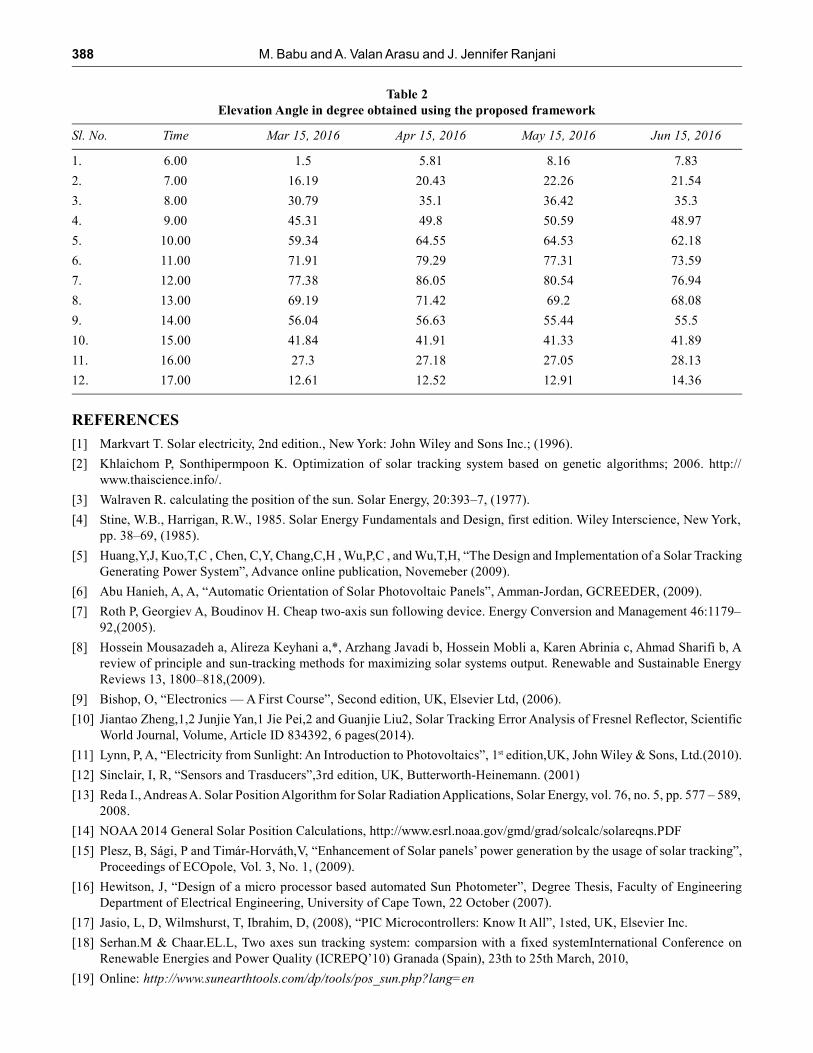
obtained from [19] over the chosen location. In Table 1, the elevation angle with respect to the Sun’s
position is observed for the chosen period over the test site are portrayed. The elevation angle of the Sun
with respect to the absorber is tabulated for every hour from 6.00 to 17.00 hours on the 15th of every month
during March 2016 to June 2016. This table can be utilized as a reference to verify the efficiency of the
proposed Arduino tracker. The elevation angles obtained for the same time interval and same duration as
the reference case was displayed in Table 2. From the table it can be verified that the proposed tracker yield
elevation tolerance with ±0.1° as average tracking error, which can be acceptable and beyond which the
efficiency of the solar thermal system is reduced by 10% of its original capability when the focusing is
perfect.
5. CONCLUSION
In the proposed work, an Arduino based tracking mechanism is proposed for LFRSC system to attain
maximum efficiency by positioning the reflector frame with an acceptable angle towards the Sun. The
proposed tracker comprises of two LDR sensor placed within an opaque box. The Arduino microcontroller
lies at the core of the proposed framework. The Arduino controller is used as a decision control logic to
detect when the reflector frame should be moved based on unit increment or using the Sun positioning
algorithm. The elevation angles obtained using the proposed system is verified against the data obtained
for Sun Earth tool. The Arduino proposed tracking system provides a cost effective and accurate solution to
the tracking problem.

386 M. Babu and A. Valan Arasu and J. Jennifer Ranjani
Figure 7: Hardware Connection

Arduino based Sun Positioning for Linear Fresnel Solar Concentrating System... 387
Figure 8: Movement of Sun
Table 1
Elevation Angle in degree obtained from sun earth tools
Sl. No. Time Mar 15, 2016 Apr 15, 2016 May 15, 2016 Jun 15, 2016
1. 6.00 1.41 5.73 8.07 7.75
2. 7.00 16.12 20.34 22.17 21.46
3. 8.00 30.76 35.01 36.34 35.22
4. 9.00 45.22 49.72 50.50 48.89
5. 10.00 59.26 64.46 64.44 62.09
6. 11.00 71.82 79.20 77.22 73.50
7. 12.00 77.28 85.95 80.39 76.79
8. 13.00 69.05 71.24 69.01 67.96
9. 14.00 55.92 56.50 55.26 55.31
10. 15.00 41.74 41.78 41.15 41.79
11. 16.00 27.22 27.10 26.97 28.05
12. 17.00 12.56 12.46 12.85 14.30
388 M. Babu and A. Valan Arasu and J. Jennifer Ranjani
Table 2
Elevation Angle in degree obtained using the proposed framework
Sl. No. Time Mar 15, 2016 Apr 15, 2016 May 15, 2016 Jun 15, 2016
1. 6.00 1.5 5.81 8.16 7.83
2. 7.00 16.19 20.43 22.26 21.54
3. 8.00 30.79 35.1 36.42 35.3
4. 9.00 45.31 49.8 50.59 48.97
5. 10.00 59.34 64.55 64.53 62.18
6. 11.00 71.91 79.29 77.31 73.59
7. 12.00 77.38 86.05 80.54 76.94
8. 13.00 69.19 71.42 69.2 68.08
9. 14.00 56.04 56.63 55.44 55.5
10. 15.00 41.84 41.91 41.33 41.89
11. 16.00 27.3 27.18 27.05 28.13
12. 17.00 12.61 12.52 12.91 14.36
REFERENCES
[1] Markvart T. Solar electricity, 2nd edition., New York: John Wiley and Sons Inc.; (1996).
[2] Khlaichom P, Sonthipermpoon K. Optimization of solar tracking system based on genetic algorithms; 2006. http://
www.thaiscience.info/.
[3] Walraven R. calculating the position of the sun. Solar Energy, 20:393–7, (1977).
[4] Stine, W.B., Harrigan, R.W., 1985. Solar Energy Fundamentals and Design, first edition. Wiley Interscience, New York,
pp. 38–69, (1985).
[5] Huang,Y,J, Kuo,T,C , Chen, C,Y, Chang,C,H , Wu,P,C , and Wu,T,H, “The Design and Implementation of a Solar Tracking
Generating Power System”, Advance online publication, Novemeber (2009).
[6] Abu Hanieh, A, A, “Automatic Orientation of Solar Photovoltaic Panels”, Amman-Jordan, GCREEDER, (2009).
[7] Roth P, Georgiev A, Boudinov H. Cheap two-axis sun following device. Energy Conversion and Management 46:1179–
92,(2005).
[8] Hossein Mousazadeh a, Alireza Keyhani a,*, Arzhang Javadi b, Hossein Mobli a, Karen Abrinia c, Ahmad Sharifi b, A
review of principle and sun-tracking methods for maximizing solar systems output. Renewable and Sustainable Energy
Reviews 13, 1800–818,(2009).
[9] Bishop, O, “Electronics — A First Course”, Second edition, UK, Elsevier Ltd, (2006).
[10] Jiantao Zheng,1,2 Junjie Yan,1 Jie Pei,2 and Guanjie Liu2, Solar Tracking Error Analysis of Fresnel Reflector, Scientific
World Journal, Volume, Article ID 834392, 6 pages(2014).
[11] Lynn, P, A, “Electricity from Sunlight: An Introduction to Photovoltaics”, 1st edition,UK, John Wiley & Sons, Ltd.(2010).
[12] Sinclair, I, R, “Sensors and Trasducers”,3rd edition, UK, Butterworth-Heinemann. (2001)
[13] Reda I., Andreas A. Solar Position Algorithm for Solar Radiation Applications, Solar Energy, vol. 76, no. 5, pp. 577 – 589,
2008.
[14] NOAA 2014 General Solar Position Calculations, http://www.esrl.noaa.gov/gmd/grad/solcalc/solareqns.PDF
[15] Plesz, B, Sági, P and Timár-Horváth,V, “Enhancement of Solar panels’ power generation by the usage of solar tracking”,
Proceedings of ECOpole, Vol. 3, No. 1, (2009).
[16] Hewitson, J, “Design of a micro processor based automated Sun Photometer”, Degree Thesis, Faculty of Engineering
Department of Electrical Engineering, University of Cape Town, 22 October (2007).
[17] Jasio, L, D, Wilmshurst, T, Ibrahim, D, (2008), “PIC Microcontrollers: Know It All”, 1sted, UK, Elsevier Inc.
[18] Serhan.M & Chaar.EL.L, Two axes sun tracking system: comparsion with a fixed systemInternational Conference on
Renewable Energies and Power Quality (ICREPQ’10) Granada (Spain), 23th to 25th March, 2010,
[19] Online: http://www.sunearthtools.com/dp/tools/pos_sun.php?lang=en

