References: Snel’s Law and...
18
ESCI 340 - Cloud Physics and Precipitation Processes Lesson 13 - Atmospheric Optical Phenomena Dr. DeCaria References: One of the best sources for information about atmospheric optics is the Atmospheric Optics website, http://www.atoptics.co.uk Snel’s Law and Refraction • The index of refraction for a medium is defined as m = c/˜ c, (1) where c is the speed of light in a vacuum, and ˜ c is the speed of light in the medium. 1 • As light passes from one medium into another, there is both reflection and refraction. • Refraction occurs because the wave fronts bend as they cross from one medium into another, causing a ray of light to bend. The ray bends toward the medium that has the slower speed of light (highest index of refraction). • The bending of the ray is quantified by Snel’s Law, which is stated mathematically as sin θ 1 sin θ 2 = m 2 m 1 , (2) where θ 1 is the angle of incidence (and reflection), θ 2 is the angle of refraction, and m 1 and m 2 are the indices of refraction in the two mediums (see Fig. 1). • The amount by which a ray of light is deflected due to refraction can be quantified in one of two ways. – The bending angle , θ 0 , is the interior angle between the initial and final rays. – The deviation angle , θ 00 , is the complement of the bending angle, θ 00 = 180 ◦ - θ 0 . – The relationship between bending angle and deviation angle is illustrated in Fig. 2. Index of Refraction for Air • Light travels faster through warm air than it does through cold air. Therefore, the index of refraction for visible light in air decreases with increasing temperature. • Figure 3 shows m - 1 as a function of temperature for yellow light. 1 Technically the index of refraction is a complex number, with the real part defined by (1), and the imaginary part linked to the extinction or absorption of light in the medium. 1
Transcript of References: Snel’s Law and...

ESCI 340 - Cloud Physics and Precipitation ProcessesLesson 13 - Atmospheric Optical Phenomena
Dr. DeCaria
References:
One of the best sources for information about atmospheric optics is the Atmospheric Opticswebsite, http://www.atoptics.co.uk
Snel’s Law and Refraction
• The index of refraction for a medium is defined as
m = c/c̃, (1)
where c is the speed of light in a vacuum, and c̃ is the speed of light in the medium.1
• As light passes from one medium into another, there is both reflection and refraction.
• Refraction occurs because the wave fronts bend as they cross from one medium intoanother, causing a ray of light to bend. The ray bends toward the medium that hasthe slower speed of light (highest index of refraction).
• The bending of the ray is quantified by Snel’s Law, which is stated mathematically as
sin θ1sin θ2
=m2
m1
, (2)
where θ1 is the angle of incidence (and reflection), θ2 is the angle of refraction, and m1
and m2 are the indices of refraction in the two mediums (see Fig. 1).
• The amount by which a ray of light is deflected due to refraction can be quantified inone of two ways.
– The bending angle , θ′, is the interior angle between the initial and final rays.
– The deviation angle , θ′′, is the complement of the bending angle, θ′′ = 180◦−θ′.– The relationship between bending angle and deviation angle is illustrated in Fig. 2.
Index of Refraction for Air
• Light travels faster through warm air than it does through cold air. Therefore, theindex of refraction for visible light in air decreases with increasing temperature.
• Figure 3 shows m− 1 as a function of temperature for yellow light.
1Technically the index of refraction is a complex number, with the real part defined by (1), and theimaginary part linked to the extinction or absorption of light in the medium.
1

Figure 1: Illustration of Snel’s Law.
Figure 2: Relationship between bending angle, θ′, and deviation angle, θ′′.
• The index of refraction for visible light in air decreases with increasing wavelength.
• Figure 4 below shows m− 1 as a function of wavelength.
• The change of the index of refraction in air over the visible wavelengths is very small,but shorter wavelengths do travel more slowly than do longer wavelengths, and willtherefore bend more when passing from one medium to another.
Mirages
• Mirages are caused by the bending of light rays either upward or downward near theground.
• If the air near the ground is very hot, the light rays will bend upward.
2

Figure 3: Index of refraction in air for yellow light (λ = 0.58µm) as a function of temperatureat p = 1013.25 mb.
– This causes objects far away to appear inverted, and underneath their actualposition
– This results in an inferior image.
– This is what causes hot asphalt to appear wet up ahead, because the sky appearsas an inferior image in the road.
• If the air near the ground is very cold, the light rays bend downward.
– This causes far away objects to appear above their actual position
– This results in a superior image
– This can actually allow objects that are over the horizon to be seen.
Primary Rainbows
• Rainbows are caused by the refraction and reflection of light by rain and cloud drops.
• The index of refraction for water is much larger than that for air, and also depends onwavelength.
• The index of refraction is greater for shorter wavelengths, so therefore, shorter wave-lengths bend more.
• Figure 5 shows the path of a light ray through a spherical water droplet for a primaryrainbow.
3

Figure 4: Index of refraction in air for visible light as a function of wavelength (T = 15◦C;p = 1013.25 mb).
– The interior angle θ′ between the incoming and outgoing rays is called the bendingangle.
• Figure 6 is an enhanced view of the path of light through a droplet.
– From the figure and using Snel’s Law we have
sin θisinα
=mw
ma
, (3)
where mw is the refractive index of liquid water, and ma is the refractive index ofair.
– The angles of the bold, brown triangle must sum to 180◦, and so
(θi − α) + (180◦ − (α + θ′/2) = 180◦,
orθ′ = 4α− 2θi. (4)
– From (3) we know that
α = arcsin
(ma
mw
sin θi
),
and so (4) becomes
θ′ = 4 arcsin
(ma
mw
sin θi
)− 2θi. (5)
4

Figure 5: Path of light through a droplet for a primary rainbow.
• There are an infinite number of possible incidence angles, and therefore paths, throughthe droplet. Figure 7 shows the bending angle as a function of incidence angle, calcu-lated using (5).
– Note from Fig. 7 that there is a certain incidence angle, θ̃i, at which the bendingangle has a maximum value.
– At this particular incidence angle slight changes in θi lead to no change in θ′.
– At this special incidence angle, the light beam will be very concentrated. At otherincidence angles, the light beam will not be as concentrated.
– It is only for this special incidence angle that a primary rainbow will be visible.
– θ̃i is found by taking ∂θ′/∂θi = 0 and solving for θi. The result is
cos2 θ̃i =1
3
(m2
w
m2a
− 1
). (6)
• If we use the value θ̃i in (5), then we obtain the value of the bending angle for ourrainbow, which we will call θ̃′.
• Since mw is around 1.33 while ma is around 1.0003, we can without much error, use
mw
ma
∼= mw.
Therefore, the equations for the incidence angle and bending angle for the primaryrainbow (from (5) and (6)) are often written as
cos2 θ̃i =1
3(m2
w − 1) (7)
5
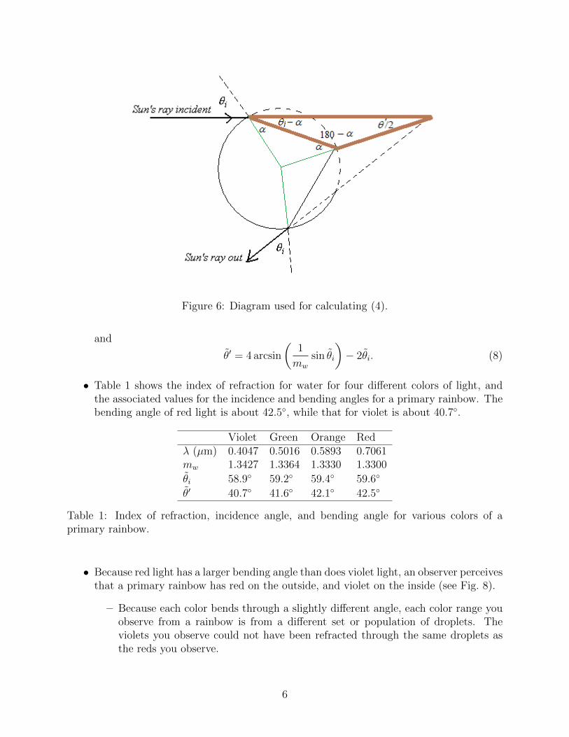
Figure 6: Diagram used for calculating (4).
and
θ̃′ = 4 arcsin
(1
mw
sin θ̃i
)− 2θ̃i. (8)
• Table 1 shows the index of refraction for water for four different colors of light, andthe associated values for the incidence and bending angles for a primary rainbow. Thebending angle of red light is about 42.5◦, while that for violet is about 40.7◦.
Violet Green Orange Redλ (µm) 0.4047 0.5016 0.5893 0.7061mw 1.3427 1.3364 1.3330 1.3300
θ̃i 58.9◦ 59.2◦ 59.4◦ 59.6◦
θ̃′ 40.7◦ 41.6◦ 42.1◦ 42.5◦
Table 1: Index of refraction, incidence angle, and bending angle for various colors of aprimary rainbow.
• Because red light has a larger bending angle than does violet light, an observer perceivesthat a primary rainbow has red on the outside, and violet on the inside (see Fig. 8).
– Because each color bends through a slightly different angle, each color range youobserve from a rainbow is from a different set or population of droplets. Theviolets you observe could not have been refracted through the same droplets asthe reds you observe.
6

Figure 7: Primary rainbow bending angle as a function of incidence angle.
• If the Sun is more than 42.5◦ above the horizon then a primary rainbow cannot be seenby a ground-based observer.
Secondary Rainbows
• It is also possible to have a path through the water droplet that has two internalreflections, such as that shown in Fig. 9.
• The relation between the bending angle, θ′, and the incidence angle, θi, is worked outby deducing the following four independent relationships from Fig. 9,
θi/2 + α + β = 180◦ (9)
θt + γ = 90◦ (10)
3γ + β = 180◦ (11)
θi + α = 180◦, (12)
and eliminating the angles α, β, and γ from (9)–(12) to get
θ′ = 180◦ + 2θi − 6θt. (13)
– From Snel’s Law we havesin θisin θt
=mw
ma
∼= mw, (14)
or
θt = arcsin
(1
mw
sin θi
). (15)
7

Figure 8: Viewing geometry for a primary rainbow. Red appears on top, because it has alarger bending angle.
– Substituting (15) into (13) yields
θ′ = 180◦ + 2θi − 6 arcsin
(1
mw
sin θi
). (16)
• As before, there are an infinite number of possible incidence angles; however, there isone special path for which ∂θ′/∂θi = 0, and at this incidence angle the light will beconcentrated. This special incidence angle is given by
cos2 θ̃i =1
8(m2
w − 1), (17)
and the bending angle for a secondary rainbow is therefore
θ̃′ = 180◦ + 2θ̃i − 6 arcsin
(1
mw
sin θ̃i
). (18)
• Table 2 shows the incidence and bending angles for four colors for a secondary rainbow.
Violet Green Orange Redλ (µm) 0.4047 0.5016 0.5893 0.7061mw 1.3427 1.3364 1.3330 1.3300
θ̃i 71.5◦ 71.7◦ 71.8◦ 71.9◦
θ̃′ 53.4◦ 51.8◦ 50.9◦ 50.1◦
Table 2: Index of refraction, incidence angle, and bending angle for various colors of asecondary rainbow.
8

Figure 9: Path of light through a secondary rainbow.
• For a secondary rainbow the shorter wavelengths have a larger bending angle. There-fore, the order of the colors of for a secondary rainbow is reversed from that of theprimary rainbow.
• Secondary rainbows are also much dimmer than primary rainbows, because every timethe light refracts and/or reflects, some of the radiance is lost out of the beam.
• If the Sun is more than 50◦ above the horizon then a secondary rainbow is not visibleto a ground-based observer.
Alexander’s Dark Band
• The maximum bending angle for light experiencing only one reflection inside a dropletis about 42◦.
• The minimum bending angle for light experiencing two reflections inside a droplet isabout 50◦.
• Between these two limits there is no light being bent from the droplets toward theobserver, as shown in Fig. 10. The result is a region of relative darkness between theprimary and secondary rainbows.
• The band of darkness is known as Alexander’s dark band, after Alexander of Aphro-disias, who wrote about this phenomenon in the year 200.
Other Types of Rainbows
• Higher order rainbow involve more than two internal reflections inside the water droplet.
9

Figure 10: Bending versus incidence angle for primary and secondary rainbows. There are nobending angles between 42◦ and 50◦ for either type of rainbow, resulting in relative darknessbetween the bows.
– Higher order bows are much fainter, because every internal reflection results in aloss of light from the beam.
– Many higher order bows also have bending angles of more than 90◦, meaning youhave to be looking toward the sun to see them, which makes them more difficultto see.
• Supernumerary rainbows are concentric arcs that appear on the inside of a primaryrainbow.
– Supernumeraries appear very close to each other, and are often greenish or pur-plish.
– If two rays of the same color take very slightly different paths through the droplet,then they may either constructively interfere with each other, enhancing thebrightness, or they may destructively interfere with each other, decreasing thebrightness of the beam.
– To form supernumeraries the droplets must be fairly uniform, nearly spherical
10

raindrops (so therefore, small droplets).
• Sometimes the top of a rainbow will appear to be ’twinned’. This is thought to be dueto the nonspherical shape of large raindrops as they fall, causing the light rays to bendthrough a different angle than they would through a spherical drop.
• See http://www.atoptics.co.uk for more detailed information on higher order, supernu-merary, and other types of rainbows.
Corona
• Corona appear as colored rings around the sun or moon.
• They are smaller than the 22◦ halo.
• Corona are formed by diffraction of light through cloud droplets, and sometimesthrough cloud ice crystals.
Ice Crystals as Prisms
• Ice crystals come in many different shapes, or habits (plates, columns, needles, etc.).
– The habit depends on the temperature and humidity at which the crystal forms.
– Most ice crystals are six-sided (hexagonal).
• Ice crystals act as prisms, refracting the light as it passes through the crystal.
• Figure 11 shows some possible symmetric paths of light through a hexagonal column.
Figure 11: Paths of light through a hexagonal ice crystal column or plate.
• One path is for the light to pass laterally across the crystal, shown on the left of Fig. 11.
– In this case, the crystal acts like a prism with an angle of 60◦.
• The other possible path is for the light to pass longitudinally along the crystal, asshown on the right of Fig. 11.
11

– In this case, the crystal acts like a prism with an angle of 90◦.
• A third path, shown in Fig. 12, is impossible for ice crystals because the index ofrefraction for ice is too large.
Figure 12: Invalid path of light through a hexagonal ice crystal column.
• The deviation angle θ′′ from a prism depends on the incidence angle θi, the index ofrefraction of the prism, m, and the angle of the prism, A. The formula is
θ′′ = θi − A+ arcsin
(m sin
[A− arcsin
(sin θim
)]), (19)
the derivation of which is shown in the Appendix.
• Figure 13 shows the relationship between deviation angle and incidence angle from(19) for the two possible paths through an ice crystal for three different wavelengthsof light; 0.70µm, 0.58µm, and 0.40µm. The indices of refraction for these wavelengthsare 1.3070, 1.3100, and 1.3195.2
• Note that there is a minimum deviation angle at which ∂θ′′/∂θi = 0, and for whichthe beam through the prism will be concentrated. This concentrated path also hap-pens to be the path that passes symmetrically through the prism (also derived in theAppendix).
• The minimum deviation angle is given by
θ′′min = 2 arcsin
[m sin
(A
2
)]− A. (20)
• The index of refraction for ice is wavelength-dependent, and is larger for shorter wave-lengths.
– Because of this wavelength dependence, red light has the smallest deviation angle,while violet light has the largest deviation angle.
– When sunlight refracts through ice crystals, the red light appears on the side ofthe phenomenon that is closer to the sun, while the blue/violet light appears onthe side further from the sun.
2Data are from Warren, S. G., 1984: Optical constants of ice from theultraviolet to the microwave.Appl. Opt., 23, 1206-1224.
12

Ice Crystal Optical Phenomena
• Halos, sun dogs (also called parhelia), sun pillars, and various arcs are caused by thereflection or refraction of sunlight from ice crystals.
• Figure 11 illustrates the locations with respect to the sun of some of these phenomena.
• Which phenomena occur depends on the shape and orientation of the ice crystals.
Halos: Halos occur when columnar crystals are randomly oriented. This results in aring around the sun or moon.
– Halos are displaced either 22◦ or 46◦, depending on the path of light throughthe crystal.
– The 46◦ halo is actually quite rare. Many reports of partial 46◦ halos areinstead pieces of supralateral or infralateral arcs, which also occur near 46◦
from the sun.
Sun dogs (parhelia): Sun dogs appear 22◦ to either side of the sun, and occur whenthe ice crystals are hexagonal plates, rather than columns. The plates must befairly uniformly oriented horizontally.
Tangent arcs: Tangent arcs touch the 22◦ degree halo at either that top (upper tan-gent arc) or bottom (lower tangent arc) of the halo.
– Tangent arcs form when hexagonal columns are nearly uniformly orientedwith the long axis parallel to the horizon (the rotation of the long axis aboutthe vertical is unimportant, as long as the long axis is nearly horizontal).
– The rays through the ice crystals are most concentrated at the minimumdeviation angle of 22◦, but the larger deviations also occur, which gives riseto the ’wings’ of the tangent arcs.
– The shape of the tangent arc’s wings change depending on how far the sun isabove the horizon.
– If the sun angle is less than 29◦ the upper and lower tangent arcs merge toform the circumscribed halo.
Circumzenithal arc: The circumzenithal arc is formed by light rays bending throughhexagonal plate crystals that are fairly uniformly oriented (the same conditionsfavorable for sun dog formation).
– For the circumzenithal arc the light path through the crystals is through thetop plate face and then out one of the sides (a prism with A = 90◦) as shownin Fig. 15.
– Refering to Fig. 13 we see that for the A = 90◦ prism path through ice, thatthe minimum angle of incidence, θi is about 58◦. The relation between sunangle and incidence angle is ψ = 90 − θi. Therefore, the sun angle must beless than 32◦ in order for a circumzenithal arc to form.
13

– Figure 13 also shows us that the minimum deviation, and hence the mostconcentrated beam, occurs when the incidence angle is about 68◦, whichequates to a sun angle of 22◦. Thus, circumzenithal arcs are most vivid andpronounced when the sun is 22◦ above the horizon.
Parhelic circle: The parhelic circle forms from external and internal reflections fromthe vertical faces of crystals. It is always at the same height above the horizon asthe sun itself.
Supralateral and infralateral arcs: These arcs are formed by light passing throughhorizontally-oriented hexagonal columns, as shown if Fig. 16.
– There may be internal reflections along the path.
– Supraleral arcs cannot form at sun angles greater than 32◦, for the samereason that circumzenithal arcs cannot form at higher sun angles.
– Supralateral and infralateral are rare, but are more common than the 46◦ halo.Most reports of pieces of the 46◦ halo are likely supralateral or infralateralarcs.
Sun pillars: Sun pillars are formed by reflections off of the upper or lower faces ofplate-like crystals.
Appendix - Deviation Angle for a Prism
• Figure 17 shows a ray passing through a prism of angle A at an arbitrary incidenceangle θi. The ray exits at an angle θo.
• From the diagram we can deduce the following relations:
A = α + β (21)
θ′′ = (θo − β) + (θi − α). (22)
• From Snel’s law we know that θo is given by
θo = arcsin(m sin β), (23)
so that (22) becomesθ′′ = arcsin(m sin β) − β + θi − α. (24)
• From (21) we can write β = A− α, and using this in (24) we get
θ′′ = arcsin[m sin(A− α)] − (A− α) + θi − α,
which simplifies toθ′′ = arcsin[m sin(A− α)] − A+ θi. (25)
14
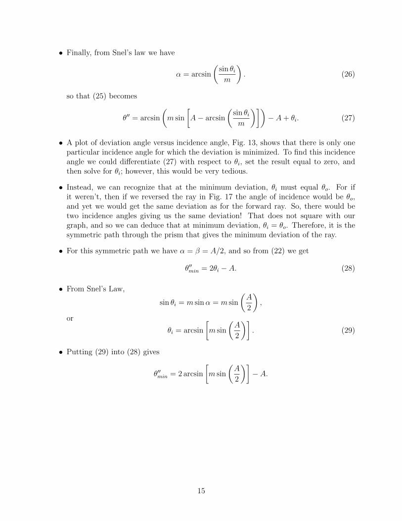
• Finally, from Snel’s law we have
α = arcsin
(sin θim
). (26)
so that (25) becomes
θ′′ = arcsin
(m sin
[A− arcsin
(sin θim
)])− A+ θi. (27)
• A plot of deviation angle versus incidence angle, Fig. 13, shows that there is only oneparticular incidence angle for which the deviation is minimized. To find this incidenceangle we could differentiate (27) with respect to θi, set the result equal to zero, andthen solve for θi; however, this would be very tedious.
• Instead, we can recognize that at the minimum deviation, θi must equal θo. For ifit weren’t, then if we reversed the ray in Fig. 17 the angle of incidence would be θo,and yet we would get the same deviation as for the forward ray. So, there would betwo incidence angles giving us the same deviation! That does not square with ourgraph, and so we can deduce that at minimum deviation, θi = θo. Therefore, it is thesymmetric path through the prism that gives the minimum deviation of the ray.
• For this symmetric path we have α = β = A/2, and so from (22) we get
θ′′min = 2θi − A. (28)
• From Snel’s Law,
sin θi = m sinα = m sin
(A
2
),
or
θi = arcsin
[m sin
(A
2
)]. (29)
• Putting (29) into (28) gives
θ′′min = 2 arcsin
[m sin
(A
2
)]− A.
15

Figure 13: Deviation angle versus incidence angle for ice crystals. The three colored linesare for wavelengths corresponding to red, yellow, and violet light (0.70µm, 0.58µm, and0.40µm). The minimum deviation angle for yellow light (shown by the dashed horizontallines) is either 22◦ or 46◦, depending on which path through the crystal the ray traverses.
16

Figure 14: Schematic showing various optical phenomena associated with ice crystals:a. parhelia (sun dogs); b. 22◦ halo; c. 46◦ halo; d. sun pillars; e. upper-tangent arc; f. cir-cumzenithal arc; g. lower-tangent arc; h. parhelic circle; i. infraleral arc; j. supralateral arc.
Figure 15: Path of light through a horizontally-oriented hexagonal plate, resulting in forma-tion of a circumzenthal arc.
17

Figure 16: Path of light through a horizontally-oriented hexagonal hexagonal column, re-sulting in formation of supralateral and infralateral arcs.
Figure 17: Ray passing through a prism at an arbitrary incidence angle.
18