Reducing California PV Balance of System Costs by...
67
Reducing California PV Balance of System Costs by Automating Array Design, Engineering and Component Delivery Final Project Webinar Tuesday December 18, 2012
Transcript of Reducing California PV Balance of System Costs by...

Reducing California PV Balance of System Costs by Automating
Array Design, Engineering and Component Delivery
Final Project Webinar Tuesday December 18, 2012
Agenda
1
• Introductions
• Project Scope and Vision
• Automated Layout and Design Tools
• Document Management
• California Permitting Agency Database
• Shaking Table Experiments
• SunLink Publications
• Building Code Developments
• Wrap Up
• Questions and Answers

Introductions
2
SunLink
Mike Williams SVP Engineering and PI
Rob Ward Chief Structural Engineer
Kate Miller P.E.
Chris Harbich Project Engineer
Eric Franzen Director, Operations & IT
Rutherford and Chekene
Andreas Schellenberg Ph.D., P.E.

3

Precision RMS Ballasted GMS
Combiner Boxes Core RMS Large-Scale GMS
SunLink Overview

SunLink’s Project Partners

Thanks!
6
REDUCING CALIFORNIA PV BOS COSTS

BoS Definition
Balance of System = (Installed Cost of PV Array) – (Cost of Modules):
• Mounting System
• Inverters (typically)
• Wiring and wiring management components
• Combiner Boxes
• Monitoring
• Installation labor
• Engineering and permitting fees
• Interconnection fees
• Financing costs

Solar PV BoS Costs
9
Chinese c-Si PV module prices ($/W) (1)
“ Half of the installed cost of a solar PV array is the solar module, but the other half (the "balance of system") involves labor, assembly, and other components. With module prices continually falling, significant decreases in total installed cost depend on reducing balance of system costs. ”

Reducing PV BoS Costs in California
What’s Needed: • Design optimization tools
– Lower design time and costs
– All project sizes
• Documentation tools
– Done faster
– Less opportunity for error
• Consistent state-wide acceptance criteria
– Understood by plan reviewers
– Accepted by the engineering community
– Allows for optimal designs
– Demonstrated code-level performance
10
Project Tasks: • Structural Design Automation
• Documentation Automation
• Wiring Software and Components
• Document Management
• Permitting Database
• Seismic and Wind Research
• Industry Publications

Reducing PV BoS Costs in California
What’s Needed: • Design optimization tools
– Lower design time and costs
– All project sizes
• Documentation tools
– Done faster
– Less opportunity for error
• Consistent state-wide acceptance criteria
– Understood by plan reviewers
– Accepted by the engineering community
– Allows for optimal designs
– Demonstrated code-level performance
11
Project Tasks: • Structural Design Automation
• Documentation Automation
• Wiring Software and Components
• Document Management
• Permitting Database
• Seismic and Wind Research
• Industry Publications

Reducing PV BoS Costs in California
What’s Needed: • Design optimization tools
– Lower design time and costs
– All project sizes
• Documentation tools
– Done faster
– Less opportunity for error
• Consistent state-wide acceptance criteria
– Understood by plan reviewers
– Accepted by the engineering community
– Allows for optimal designs
– Demonstrated code-level performance
12
Project Tasks: • Structural Design Automation
• Documentation Automation
• Wiring Software and Components
• Document Management
• Permitting Database
• Seismic and Wind Research
• Industry Publications

Reducing PV BoS Costs in California
What’s Needed: • Design optimization tools
– Lower design time and costs
– All project sizes
• Documentation tools
– Done faster
– Less opportunity for error
• Consistent state-wide acceptance criteria
– Understood by plan reviewers
– Accepted by the engineering community
– Allows for optimal designs
– Demonstrated code-level performance
13
Project Tasks: • Structural Design Automation
• Documentation Automation
• Wiring Software and Components
• Document Management
• Permitting Database
• Seismic and Wind Research
• Industry Publications

AUTOMATED LAYOUT AND DESIGN TOOLS
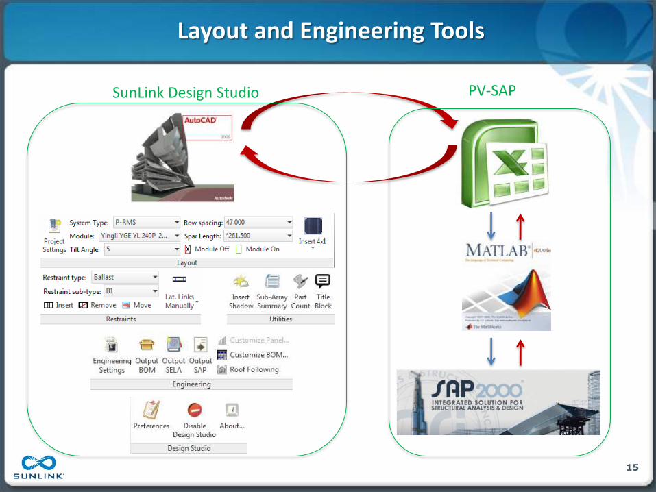
Layout and Engineering Tools
15
PV-SAP SunLink Design Studio
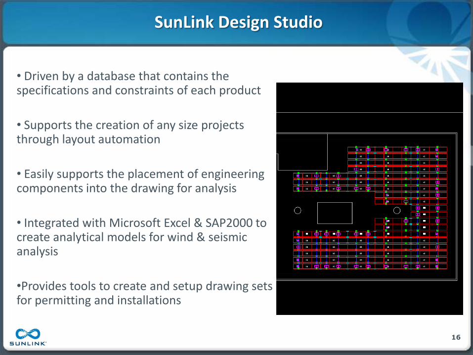
SunLink Design Studio
16
• Driven by a database that contains the specifications and constraints of each product
• Supports the creation of any size projects through layout automation
• Easily supports the placement of engineering components into the drawing for analysis
• Integrated with Microsoft Excel & SAP2000 to create analytical models for wind & seismic analysis
•Provides tools to create and setup drawing sets for permitting and installations

SunLink Design Studio Demonstration
17

PV-SAP Automation
18
• SunLink’s Structural Engineering Load Advisory (SELA) generated from Design Studio
• Uploads all project specific inputs to calculate Wind, Seismic, and Snow loads
• Automatically formatted to provide as customer deliverable

PV-SAP Automation Cont.
19
• Analyzes structural model generated from Design Studio
• Writes and reports all results to the SELA excel document
• Graphical user interface (GUI) allows ease of interpreting results

Benefits to California
20
• Better customer communication
• Lower cost of PV systems by quickly automating multiple layouts
• Reduce design time for both SunLink and its customers
• Deliver projects with less opportunity for error

DOCUMENT MANAGEMENT

Why Investigate DMS?
• Solar projects involve a number of documents including drawings, contracts, engineering reports, permitting documents, etc.
• Challenges:
– Locating files on a file share
– Version Control
– Security
– Document Processes
– Collaboration
– Sharing documents with external partners
• Seek more efficient means of working with documents

Process
23
• Gathered high level requirements
• Held interdepartmental workshops to establish process steps, activities, and associated documents and data
– Workflow Drawing & Excel Workbook
• Researched document management system capabilities and offerings
• Established scope for evaluating DMS
– Roof mount products
– Quote Request -> Customer Contract
• Selected DMS for pilot
• DMS configuration
• DMS pilot
24
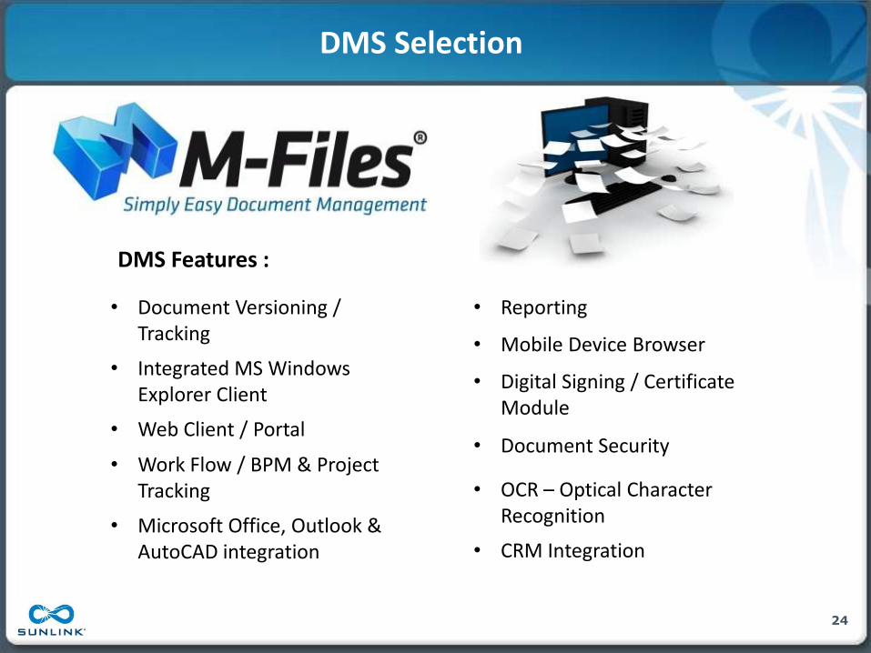
DMS Selection
• Document Versioning / Tracking
• Integrated MS Windows Explorer Client
• Web Client / Portal
• Work Flow / BPM & Project Tracking
• Microsoft Office, Outlook & AutoCAD integration
• Reporting
• Mobile Device Browser
• Digital Signing / Certificate Module
• Document Security
• OCR – Optical Character Recognition
• CRM Integration
DMS Features :

DMS Pilot Architecture
25
Mobile Devices
ODBC ERP
CRM
API Web Portal
PC Client

DMS Screen Shots
26

DMS Pilot Feedback
27

Benefits to California
28
• Established Document Management systems can play a vital role in creating organizational efficiencies and reducing errors
• Our work serves as a starting point for solar organizations to pursue document management
• Identified and reviewed DMS products
• Identified key functionality and features worthy of consideration as DMS selection criteria

CALIFORNIA PERMITTING AGENCY DATABASE

Benefits of the Database Application
30
• Improve visibility and efficiency of permitting process in California
• Improve communication between building owners, solar installers, engineers, and permitting departments
• Reduce the time and effort required in gathering engineering requirements
• Encourage future universal code requirements for solar installations

What it Does
31
• Web-accessible database application
– Engineering parameters for solar projects
– Building official contact information
– Links to adopted building codes
– 1,527 California cities and towns already added
http://ec2-54-245-104-33.us-west-2.compute.amazonaws.com/

The Future of the Database
32
• SunLink-hosted for one year
• Administrator privileges to be determined
– Potential to transition to a public wiki
• Future database management

SHAKING TABLE EXPERIMENTS

Unattached PV Solar Arrays
34
Rooftop arrays where ballast, self-weight, and friction provide wind resistance.
THE ADVANTAGE:
• Overall reduced project costs – Installation
• Penetrations, flashing, etc.
– Maintenance
THE CHALLENGE:
• Seismic design in high seismic areas – Code-level “life safety”
performance

U.S. Building Codes
• Seismic design per ASCE 7
• Chapter 13 prescriptive requirements for building equipment in high seismic areas: – “…bolted, welded or otherwise
positively fastened …”
35

Part 1 - Structural Analysis
1. Build structural analysis models that accurately capture the parameters that influence seismic behavior
2. Determine a set of appropriate earthquake roof motions to be used as inputs to the analyses
3. Run analyses and record sliding displacement demands
4. Develop design tables so that the engineer can look up sliding displacements for different SDS, COF and roof slope values
36
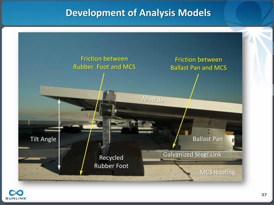
Development of Analysis Models
37
Recycled Rubber Foot
Tilt Angle
Galvanized Steel Link
Ballast Pan
MCS Roofing
Friction between Ballast Pan and MCS
Friction between Rubber Foot and MCS

Development of Analysis Models
38
• Friction is assumed to be constant (Coulomb friction) and is determined from pull-tests of the feet and ballast pans
• Due to the low CG sticking and sliding are the primary modes of response (no rocking, no uplift)
• Model arrays in plane w/o vertical dimensions or as lumped masses w/o internal flexibility
• Internal damping of the solar array structure is conservatively ignored

Selection of Earthquake Roof Motions
• Use roof accelerations from CSMIP database
• Use only 3-component roof motions
• Select 7 roof motions
– different earthquakes
– geographical locations
– soil conditions
– building types
39

Effect of Scaling and Spectral-Matching
40
Roof Motion 6: Transverse Direction

Shaking Table Testing
• Needed a real-world experiment to validate and calibrate the nonlinear computer analysis models developed in phase 1
41

PEER Earthquake Shaking Table Facility
• Table = 20 ft x 20 ft
• Largest 6 DOF shaking table in U.S.
• Can test structures, weighing 100,000 lbs, to horizontal accelerations of 1.5 G
• +/- 5 inches horizontal displacement capacity
• +/- 2 inches vertical displacement capacity
• +/- 40 inches/sec velocity capacity
42

43
Testing the CORE System on a 4% Incline Polyvinyl Chloride (PVC)
Roof
Switching to the Mineral Cap Sheet (MCS) Roof
Roof Surfaces

Instrumentation Setup
• 12 Wire Potentiometers
• 2 Linear Variable Displacement Transducers
• 10 Accelerometers
• 60 DAQ Channels
• Approximately 1.4 million data points/test
44

Shaking Table Video
45
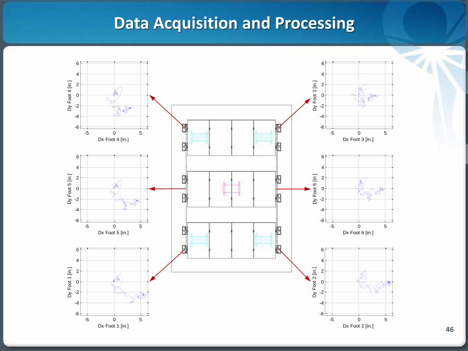
Data Acquisition and Processing
46
-5 0 5
-6
-4
-2
0
2
4
6
Foot Displacements: Run194 RM4 SDS15
Dx Foot 4 [in.]
Dy F
oot
4 [
in.]
-5 0 5
-6
-4
-2
0
2
4
6
Dx Foot 3 [in.]
Dy F
oot
3 [
in.]
-5 0 5
-6
-4
-2
0
2
4
6
Dx Foot 5 [in.]
Dy F
oot
5 [
in.]
-5 0 5
-6
-4
-2
0
2
4
6
Dx Foot 6 [in.]
Dy F
oot
6 [
in.]
-5 0 5
-6
-4
-2
0
2
4
6
Dx Foot 1 [in.]
Dy F
oot
1 [
in.]
-5 0 5
-6
-4
-2
0
2
4
6
Dx Foot 2 [in.]
Dy F
oot
2 [
in.]
-5 0 5
-6
-4
-2
0
2
4
6
Foot Displacements: Run194 RM4 SDS15
Dx Foot 4 [in.]
Dy F
oot
4 [
in.]
-5 0 5
-6
-4
-2
0
2
4
6
Dx Foot 3 [in.]
Dy F
oot
3 [
in.]
-5 0 5
-6
-4
-2
0
2
4
6
Dx Foot 5 [in.]
Dy F
oot
5 [
in.]
-5 0 5
-6
-4
-2
0
2
4
6
Dx Foot 6 [in.]
Dy F
oot
6 [
in.]
-5 0 5
-6
-4
-2
0
2
4
6
Dx Foot 1 [in.]
Dy F
oot
1 [
in.]
-5 0 5
-6
-4
-2
0
2
4
6
Dx Foot 2 [in.]
Dy F
oot
2 [
in.]

Animation of Analysis Results
47
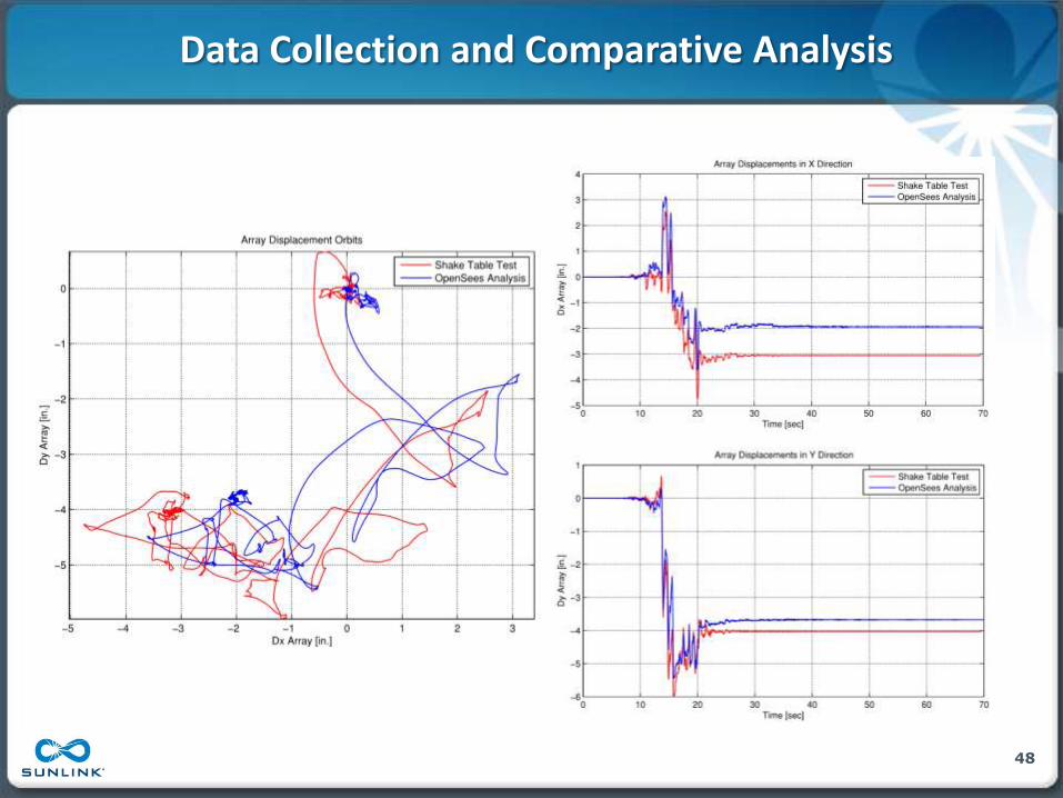
Data Collection and Comparative Analysis
48

SEISMIC R&D FINDINGS

System Movement
50
System movement during high seismic events is smaller than many think, and is manageable.

Friction
51
Friction plays a role in restraining forces during seismic events.

Roof Integrity
52
Read the full report at www.sunlink.com/seismictesting.
After 100 earthquakes each: No roof damage.

PUBLIC BENEFITS TO CALIFORNIA

Seismic R&D Benefits
54
• Greater Solar Penetration
– Decreased system and installation cost of unattached systems
– Potential for projects on building roofs previously considered unsuitable
• Furthering the conversation toward permitting unattached systems in seismic regions

INDUSTRY PUBLICATIONS

SunLink Publications
• CSI RD&D program
• Technical conferences
• SunLink white papers and webinars
• Trade journal articles
• Peer-reviewed journal papers
56

Tech Transfer 1
57
Trade Journals and Press
Carlsen, R. “U.C. Berkeley’s PEER Center Hosts Shake Test for Alternative Solar Racking System,”
Engineering News-Record, March 19, 2012
Riddell, L., “Sunlink studies seismic effects on solar,” San Francisco Business Times, March 6, 2012
Ward, R., Miller, K., “Ballasted Solar Systems in High Seismic Areas,” Solar Novus, 24 October 2012
Technical Conferences
Holland, R.H., Miller, K., and Schellenberg, A. “Approach to Parametric Analysis of Wind Load Effects on PV Solar Roof Bearing Arrays Using OpenSees” PEER OpenSees Days presentation, 16 August 2012.
Schellenberg, A., Fathali, S., Maffei, J., Miller, K., “Seismic Behavior of Unattached Solar Arrays on Flat Roofs: Analysis, Shake Table Testing, and Proposed Requirements,” Proceedings Structural Engineers Association of California / Structural Engineers Association of New Mexico Convention, Santa Fe, NM September 2012.
Tilley, C., “Accelerating BOS Cost Reduction through Integration,” 4th PV Power Plants Conference, Phoenix, AZ, November, 2012
Williams, J. M., “Engineering Challenges for Photovoltaic Power Systems,“ 2nd International Conference for Sustainable Design, Engineering and Construction, Fort Worth, TX, November 2012.

Tech Transfer 2
58
Trade Shows
Tilley, C., “Standardization of Codes for Solar Project Development,” Solar Power International Orlando, FL, September 2012
SunLink White Papers
SunLink Seismic Testing Roof Integrity Report
SunLink Webinars
Miller, K., Ward, R.,”Designing for Earthquakes: Lessons from SunLink’s Full-Scale Shaking Table Experiments,” September 25, 2012
Peer Reviewed Journals
Maffei, J., Fathali, S., Telleen, K., Ward, R., and Schellenberg, A. (2012). “Seismic Design of Ballasted Solar Arrays on Low-Slope Roofs.” Submitted to ASCE Journal of Structural Engineering, 2012
Technical Committees
Structural Engineers Association of California Solar Photovoltaic Systems Committee, “Structural Seismic Requirements and Commentary for Rooftop Solar Photovoltaic Arrays” SEAOC PV1-2012 August 2012.
Structural Engineers Association of California Solar Photovoltaic Systems Committee, “Wind Design for Low-Profile Solar Photovoltaic Arrays on Flat Roofs” SEAOC PV2-2012 August 2012.
University Lectures
Mike Williams – Stanford University – Civil and Environmental Engineering – Spring 2011 and Spring 2012
Mike Williams – UC Berkeley – Civil Engineering – Fall 2011

CALIFORNIA BUILDING CODE DEVELOPMENT

New 2012 California Guidelines
60
1. GOPR Solar Permitting Work Group: California Solar Permitting Guidebook • Residential and smaller systems
2. SEAOC PV1 – Structural Seismic
Requirements and Commentary for Rooftop Solar Photovoltaic Arrays
3. SEAOC PV2 – Wind Design for Low-Profile Solar Photovoltaic Arrays on Flat Roofs
www.seaoc.org

Path to the 2019 CBC
61
www.bsc.ca.gov www.asce.org
ASCE ICC CBSC
ASCE 7-05 2009 IBC 2010 CBC
ASCE 7-10 2012 IBC 2013 CBC*
ASCE 7-10 2015 IBC* 2016 CBC
ASCE 7-16* 2018 IBC 2019 CBC
www.iccsafe.org
* in progress

California Code Development
• 2013 California Building Code: – Housing and Community
Development: requirements for ballasted systems on residential roofs up to 1:12 slope.
• DSA IR 16-8 – Incorporates SEOAC Guidelines
from PV-1 and PV-2
62

National Code Development
• 2015 International Building Code: – Proposed language for ballasted
systems on residential roofs up to 1:12 slope.
• ASCE 7-16: – SEAOC Guidelines Presented to
Subcommittee on Rooftop PV Wind Loads
63

SUMMARY & CONCLUSIONS

The Impact of SunLink’s Project
65
• Design optimization tools • Layout and Design Tools
– Better customer communication
– Lower cost of PV systems by quickly automating multiple layouts
– Reduce design time for both SunLink and its customers
– Deliver projects with less opportunity for error
Documentation tools • Document Management
– Established Document Management systems can play a vital role in creating organizational efficiencies and reducing errors
– Our work serves as a starting point for solar organizations to pursue document management
– Identified and reviewed DMS products
– Identified key functionality and features worthy of consideration as DMS selection criteria
• Consistent state-wide acceptance criteria: • Permitting Database
• Seismic Research
– Decreased system and installation cost of unattached systems
– Potential for projects on building roofs previously considered unsuitable
– Furthering the conversation toward permitting unattached systems in seismic regions • Industry Publications

Thank You Questions?