Recommended Practices for Construction of … RecommPrac BKLT.pdfRecommended Practices for...
52
Recommended Practices for Construction of Residential Masonry Basements in Minnesota Sixth Edition Includes cold weather masonry construction guidelines and recommended radon guidelines
Transcript of Recommended Practices for Construction of … RecommPrac BKLT.pdfRecommended Practices for...

Recommended Practicesfor Construction ofResidential MasonryBasements in MinnesotaSixth Edition
Includes cold weather masonry construction guidelinesand recommended radon guidelines

Recommended Practices for Construction of Residential Masonry Basements in Minnesota (w/ Recommended One and Two Family Residential Cold Weather Masonry Construction Guidelines) 6th Edition and Radon Rules as of February 2015
© MC&MCA – 04/15 (6th Edition)
Disclaimer:The information presented in this pamphlet is intended to be used as a general construction guide and is not all encompassing. Your project may have specific conditions which dictate different construction practices. Consult your engineer, architect, or building official for job specific design and construction practices.
Section 1• Recommended Practices for Construction of Residential Masonry Basements in Minnesota pg. 1.1
Diagram/Table Pages • Diagram/Minnesota Frost Depth Map pg. A• Unified Soil Classification Chart pg. B• Diagram 1: Foundation wall (upper section) pg. C• Diagram 2: Foundation wall (lower section) pg. C• Diagram 3: Cantilevered Wall Section pg. D• Diagram 4: Propped Cantilevered Wall Section pg. E• Diagram 5: Portland Cement & Lime Card pg. F• Diagram 6: Mortar & Cement Card pg. F• Maximum Anchor Bolt Spacing pg. G• 2012 IRC Requirements pg. H-I• Tables 1-4 & 6, 7, & 8 pg. J-T
Section 2• Cold Weather Masonry Construction Guidelines pg. 2.1
Section 3• Radon Rules pg. 3.1
Produced and published by:
MC&MCA1711 West County Road BSuite 207SSaint Paul, MN 55113(651) 293-0892 Phone(651) 293-0373 Faxwww.mcmca.com
1.1
INTRODUCTION
The information presented in this publication is intended to be used as a general field construction guide and is not all encompassing.
Several phases of construction will be addressed in the basement construction process:
1. Excavation2. Concrete Footings3. Mortar & Grout4. Concrete Block Wall Construction5. Waterproofing6. Insulation7. Drainage8. Backfilling
In each phase we will highlight significant material specifications, design details and construction techniques. This information can be used to coordinate tradespeople who are collectively responsible for the construction of residential basements. The responsibilities of the excavator/backfiller, the mason contractor and the builder’s laborers will be discussed.
Graphic illustrations of the design details discussed in this publication are included for your reference and clarification.
It should be emphasized that this handbook is not a design manual or guide to the structural design of footings or walls. Each project may have specific conditions which dictate different construction practices. Consult your engineer/architect or building official for job specific design and construction details.
The goal of this publication is to emphasize the influence that each construction phase and trade has on the entire basement system. Suggestions on material selection, detailing, and construction will also be offered.
Note: This guide contains changes included in the 2015 Minnesota Residential Building Code.
Refer to the Minnesota Building Code for more information.www.dli.mn.gov/ccld/codes.asp

1.2
1. EXCAVATION
1-1 PREPARATION
1-1.1 Coordinate the foundation excavation with the mason contractor while reviewing the approved stake survey. Make sure that all underground utilities are marked and cleared (Gopher State One Call: #800-252-1166 or #651-454-0002).
1-2 EXECUTION
1-2.1 Care should be taken to remain on correct perimeter excavation lines to allow the concrete footings to be accurately aligned. Out-of-square footings may result in misalignment of the concrete block wall or possible footing failure.
1-2.2 Remove all unstable and degradable materials. Fill any such area with additional concrete or compacted granular fill.
1-2.3 Locate utility trenches. Make sure trenches are filled with granular fill and compacted prior to placement of concrete footings.
1-2.4 Limit the over-dig area to 2-4 feet beyond the outside edge of the footing location. This will provide enough room for waterproofing and drainage work while reducing the backfill weight against the wall.
1-2.5 Keep the elevation of the floor slab area 4” – 6” higher than the interior perimeter drain area (bottom of footing). By doing so, a collection channel will be created which will allow water to pass through the footing weeps or underneath the floor slab. In case of transite heat, the drain tile must be located below transite heat.
1-3 STATIONING
1-3.1 Place a layer of aggregate in the basement floor area before delivery of the concrete block to protect the concrete block from dirt and mud, and also for radon.
1-3.2 Access should be made for material deliveries such as concrete block and footing concrete.

1.3
2. CONCRETE FOOTINGS
2-1 DESIGN
2-1.1 Concrete footings must bear on soil which is beneath the maximum frost penetration depth. Refer to the [Appendix page A for the Minnesota Frost Depth Map.]
2-1.2 For most conditions typical footing size is 8” high by 16” or 20” wide. Footing dimension requirements can vary depending on soil and load conditions. Footing projections should be at least 2 inches beyond the foundation wall.
2-1.3 Footing concrete shall have a minimum compressive strength of 5,000 p.s.i. The new footing specifications require the use of concrete that can withstand 5,000 pounds of force per square inch (“5,000 psi”). These new specifications will create a water separation plane between the soil and the building foundation. Reference Table 402.2, page G. Footnote “g” permits a concrete mixture that is 2,500 psi with an approved admixture (chemicals that can be added to concrete to change its moisture permeability), which provides a water and vapor resistance equivalent to that of 5,000 psi concrete.
2-1.4 Although not always mandatory, two ½” minimum reinforcing rods (rebar) placed 3 inches from the bottom of the footing running parallel to the wall, are recommended to help avoid cracking and/or differential settlement of the footing.
2-1.5 Footings should be continuous. Footing height changes are typically accomplished by the use of vertical bulkheads reinforced with two ½” (minimum) reinforcing rods.
2-1.6 Dowels in the footings are not typically required by code for residential concrete block walls. Exception: Some Cantilever Walls conditions may require dowels. See Appendix Tables 6, 7 & 8 on page Q-T of this booklet. Reference to footnote h.
2-2 CONSTRUCTION
2-2.1 The footings should be formed and poured as soon as possible after the excavation is completed. This will avoid excessive moisture (rain, snow) from saturating the ground and possibly destabilizing the soil. If the soil does become “soft”, the area should be scraped off or re-dug. Take proper care to ensure that minimum elevation and clearance from the water table is attained.

1.4
2-3 Do not pour footings over unstable material such as tree roots, construction debris, soft spots, ice, etc. Remove all unstable material and fill resulting voids with compacted granular fill or concrete before forming or pouring footings.
2-4 Footing alignment must be accurate so that the center line of the concrete block wall stays as close as possible to the center line of the footing.
2-5 Caution should be taken when adding water to concrete in the field. Excessive water can severely reduce the strength of concrete.
2-6 Do not trowel footing surfaces. A slightly rough footing surface helps assure a good bond between the first course of concrete block and the footing.
3. MORTAR & GROUT
3-1 MORTAR • Preblended Mortar: A dry mixture of Portland
Cement, Hydrated Lime and Oven Dried Masonry Sand formulated and blended in a manufacturing facility to meet the property specification requirements of ASTM C270.
• Field Mixed Mortars: A mixture of Portland Cement, Hydrated Lime and Masonry Sand or Masonry/Mortar Cement and Masonry Sand mixed at the job site to the proportion specification requirements of ASTM C270.
3-1.1 All mortar used in foundation work should be Type S or Type M. Refer to Mortar Cards on page F.
3-1.2 Mortar may be pre-blended or proportioned on-site and should meet ASTM C270.
3-1.3 Water should be potable and should not exceed 160˚ F (71˚ C).
3-1.4 The preparation of mortar and grout in the field is an integral part of the construction of masonry walls. To provide consistent batching, materials used to charge the mixer must be controlled.

1.5
3-1.5 Pre-Blended Mortar3-1.5.1 Proper Mixing Procedures
Due to the fact that there are many types of mixers, this procedure refers to mixing masonry mortars in a standard mechanical mixer.
1. Add 2/3 of required water to an empty, clean mixer and start the mixer.
2. Add Preblended Mortar, Preblended Colored Mortar or Grout to the mixer.
3. If necessary, add remaining water to the mixer until proper consistency is achieved.
4. Mix between 3 and 10 minutes.
Note: Completely empty mortar content into wheelbarrow or container.
3-1.6 Proportioning On-Site Mortar3-1.6.1 The Mortar Cement and Masonry Cement table and
the Portland Cement and Lime table on the appendix page F of this book reference typical mortar types and proportioning using ASTM C270.
3-1.6.2 Aside from sand, mortar ingredients are typically sold prepackaged in bags by weight. Since mortar is proportioned by volume, it is necessary to know:
Cementitious Material WeightCementitious Material Pounds per Cubic Foot
Portland Cement 94
Blended & Hydraulic Cement 85 to 94*
Mortar Cement 70 to 90*
Masonry Cement 70 to 90*
Hydrated Lime 50*See weight on bag
3-1.6.3 SandA recommended method of measuring sand is by using a five gallon pail (volumetric measure). In the field, sand is typically measured by the use of a shovel. It is important to check for shovel consistency at least twice daily. Additional checks should be performed if the sand moisture content changes or if a new load of sand is delivered. A five gallon pail holds about 2/3 of a cubic foot of sand in damp, loose condition. Therefore, 3 cubic feet of sand is equal to about 4 ½ five gallon buckets.

1.6
3-1.6.4 Proper Mixing ProceduresDue to the fact that there are many types of mixers, this procedure refers to mixing masonry mortars in a mechanical mixer.
1. Add 2/3 of required water to an empty, clean mixer and start the mixer.
2. Add ½ the amount of sand required to the mixer3. Add any coloring pigments to the mixer (where
applicable).4. Add lime to the mixer (if applicable).5. Add cement to the mixer: (Cement, Masonry
Cement, or Mortar Cement).6. Add remaining sand to the mixer.7. If necessary, add remaining water to the mixer until
proper consistency is achieved.8. Mix between 3 minutes (minimum)* and 15
minutes (maximum) after adding the last of the water in step (7) above.
(* Additional mixing time up to ten minutes may be required when using mortar materials containing oven dried sand.)Note: Completely empty mortar contents into wheelbarrow or container.
3-1.6.5 Retempering Fresh mortar should be prepared at the rate it is used to maintain workability and consistency on the job site. Mortar that has been mixed but not used immediately will experience stiffening as the product dries out. To reduce this evaporation effect, you may wet the mortar board and cover the mortar in the tub or wheelbarrow. If necessary to restore workability, mortar may be retempered by adding small amounts of water. In general, mortar may be retempered up to 2 ½ hours after original mixing. Mortar over 2 ½ hours old should be discarded.
3-2 GROUT • Preblended Grout: A dry mixture of Portland
Cement, Oven Dried Masonry Sand and Aggregate formulated and blended in a manufacturing facility to meet the requirements of ASTM C476.
3-2.1 Grout may be pre-blended, proportioned on-site, or delivered by ready-mix truck and should meet ASTM C476.

1.7
3-2.2 Pre-Blended Grout3-2.2.1 Proper Mixing Procedures
Due to the fact that there are many types of mixers, this procedure refers to mixing masonry mortars in a standard mechanical mixer.
1. Add 2/3 of required water to an empty, clean mixer and start the mixer.
2. Add Grout to the mixer.3. If necessary, add remaining water to the mixer until
proper consistency is achieved.4. Mix between 3 and 10 minutes.
Note: Completely empty grout contents into wheelbarrow or container.
3-2.3 Proportioned On-Site Grout3-2.3.1 Proportions for Fine Grout Use 1 part cement mixed with 2 ¼ to 3 parts sand.
3-2.3.2 Proportions for Coarse Grout Use 1 part cement mixed with 2 ¼ parts sand and 1 to 2
parts 3/8" aggregate.
3-2.3.3 Proper Mixing ProceduresDue to the fact that there are many types of mixers, this procedure refers to mixing masonry mortars in a mechanical mixer.
1. Add 2/3 of required water to an empty, clean mixer and start the mixer.
2. Add sand and 3/8” aggregate to the mixer and mix for 30 seconds.
3. Add cement to the mixer.4. If necessary, add remaining admixtures and water to
the mixer until proper consistency is achieved.5. Mix between 3 minutes (minimum)* and 15
minutes (maximum) after adding the last of the water in step (4) above.
3-3 PROTECTING MASONRY MATERIALS Bagged Materials
• Store on pallets off the ground• Completely cover to protect from rain or snow• Stockpile on opposite side of mixer from water
supply and sand

1.8
Sand (On-site proportioning)• Place stockpile on tarp to protect from
contamination from below• Cover with tarp when not in use to maintain
consistent moisture content and avoid contaminants• Store on opposite side of mixer from bagged
materials• Store different aggregates separately to avoid cross
contamination of stockpiles
Concrete Masonry Units (CMU or Block)• Cover stockpiles to keep dry and clean. • Store away from mixing site and/or cement
materials
3-4 HOT WEATHER MORTAR AND GROUT ISSUESHot weather construction occurs when the ambient temperature exceeds 90°F with a wind velocity of greater than 8 mph.
Potential problems of hot weather construction:• Rapid loss of workability• Rapid evaporation of water required for cement
hydration and curing.
Procedures to follow when working with masonry in hot weather:
• Keep mortar, grout and CMU’s as cool as practical using techniques such as placing materials in the shade and using cool water when mixing.
• Keep any surface that comes in contact with the mortar or grout such as mixers, wheelbarrows, shovels, mortar boards, trowels damp.
• Limit the amount of mortar that is spread on the bed joints to 4 feet ahead of the CMU. Place CMU within one minute of spreading the mortar.
• In hot, dry and windy weather, lightly fog or mist the finished wall, if possible.
3-5 PROTECTION OF UNFINISHED WALLSAll unfinished walls should be covered with weather-resistant material, on both sides, from the top of the wall down to the footings for 48 hours after construction. Where necessary, install wind breaks when wind velocity exceeds 15 mph (6.7 m/s).
1.9
4. CONCRETE BLOCK WALL CONSTRUCTION
4-1 MATERIALS
4-1.1 Concrete block used for residential foundations should comply with ASTM C90. Proper care should be taken to
maintain dry concrete block prior to building the wall.
4-2 DESIGN
4-2.1 Prior to laying the first course of concrete block, review the layout, dimensions and locations of all wall openings. Determine if shorter concrete block lengths (cuts) are required. Starting your wall with the cuts (if bond will allow) or placing cuts on either side of wall openings will make for a more attractive wall.
4-2.2 Structural foundation blocks must be a minimum 6" width. Where a wall changes width, the top course of the wider block should be either a solid unit, grouted solid, or fill top block.
4-2.3 Minimum vertical reinforcement bar size and spacing for 8", 10" and 12" nominal wall thickness should comply with Tables R404.1.1 (1), R404.1.1 (2), R404.1.1 (3) or R404.1.1 (4) of the 2012 International Residential Code™ (IRC). Refer to pages J-P for tables 1-4. Alternate reinforcing bar sizes and spacing having an equivalent cross-sectional area of reinforcement per lineal foot of wall should be permitted provided the spacing of the reinforcement does not exceed 72 inches. See Footnote B for Tables 2, 3, and 4 on pages K-P with alternate bar sizes, spacing and soil classes.
Permanently supported foundation walls which are supported at the top by floor members shall have reinforcing bars positioned toward the inside face shell of the concrete block core. By positioning the reinforcing bars in this manner, the walls will have greater resistance to lateral earth pressures. The distance from the face of the soil side of the wall to the center of vertical reinforcement should be the minimum specified at each table: 8" CMU= 5", 10" CMU = 6.75" and 12" CMU = 8.75". Soil classes are in accordance with the Unified Soil Classification System referenced in IRC Table R405.1 on page B.

1.10
4-2.4 Foundation walls which are not permanently supported at the top by floor members are considered “cantilevered walls.” Refer to Footnote C on Tables 5, 6, and 7 on Appendix pages Q-T for wall reinforcement requirements for 8", 10" and 12" walls. Note footnotes (g) and (h) for conditions which may require “propped cantilevered walls” (see diagram 4 on page E) or may require doweling to the footings. Special Design is always an alternative to the tables. Another alternative is to build the wall full height to floor bearing and reinforce to Tables 2, 3 or 4 on pages K-P. Note that short walls typical to frost footing or look-out foundations do not require reinforcement.
4-2.5 The wood sill plate should be anchored to the foundation with anchor bolts spaced a maximum of 6 feet on center. See Appendix page G for maximum bolt spacing. When vertical reinforcing is required, the anchor bolts or straps should align with the reinforcing. Note: Not all bolts or straps need to be placed at corefills. Anchor bolts should also be located within 12 inches from the ends of each plate section. Note: Where longer walls require multiple sill plate sections, consider installing an additional bolt at anticipated joint locations. Bolts should be at least ½ inch in diameter and should extend a minimum of 7 inches into masonry or concrete. Anchor Bolts require a 2" diameter by 0.125" galvanized thick washer counter sunk 0.25" into top of sill plate. Foundation anchor straps may be used when spaced as required to provide equivalent anchorage to 1/2 –inch diameter (12.7 mm) anchor bolts. When vertical reinforcing is required by other sections of this code, the foundation anchor straps should align with the reinforcing.
4-3 CONSTRUCTION
4-3.1 The top of the footing must be clean, free of dirt, mud, ice or any material which might weaken the bond between the mortar and footing.
4-3.2 Lay first course of concrete block on the center line of the footing. All face shells of the concrete block should be set in mortar. Where the wall is to be grouted, mortar should be placed so it does not severely project into the cores to be grouted which will permit the grout to make full contact with the footing.
4-3.3 Lay concrete block in a running bond with a 3/8" mortar joint covering the horizontal and vertical face shells.
1.11
4-3.4 All head joints and bed joints should be filled solid with mortar for a distance measured in from the face of the unit not less than the thickness of the concrete block face shell.
4-3.5 Exterior mortar joints over which the waterproof coating is applied should be cut flush or tooled and be without voids.
4-3.6 Interior mortar joints should be firmly tooled after the mortar has become thumb print hard (when a clear thumb-print can be impressed and the cement paste does not adhere to the thumb when removed). If color consistency of the mortar joint is important, remember wet tooling will result in a light color. Dry or stiff tooling will result in dark colored mortar joint.
5. WATERPROOFING
5-1 DESIGN
5-1.1 Waterproofing is required on all foundation walls.
5-1.2 Exterior foundation walls that retain earth and enclose below grade interior spaces, floors and crawl spaces shall be waterproofed.
5-1.3 Various waterproofing systems or products may be used when approved by the building official. Manufacturer’s recommendations should be consulted for product limitations and proper installation
requirements.
5-1.4 Areas of the basement wall where porch, garage, fireplace or other walls intersect should be waterproofed. Contact the product manufacturer or distributor for specific recommendations.

1.12
5-2 CONSTRUCTION
5-2.1 Apply waterproof coating to concrete block walls that are clean, free of dirt, mud, ice or any material which might reduce the bond between the coating and the concrete block surface.
5-2.2 402.1.1 Minnesota Energy Code – 1.) The waterproofing shall extend from the top interior wall edge, across the top of the wall, and down the exterior wall face to the top of the footing. If a full width, closed-cell material is installed to create a seal between the sill plate and top of the foundation wall, the installation is deemed to meet the requirements for the top of the wall waterproofing. 2.) If the walls are exposed to the exterior environment, the waterproofing system shall have a rigid, opaque, and weather-resistant protective covering to prevent degradation of the waterproofing system. The protective covering shall cover the exposed waterproofing and extend a minimum of 6 inches (152 mm) below grade. The protective covering system shall be flashed in accordance with IRC Section R703.8.
5-2.3 Most coatings require modified mixing and application procedures when temperatures drop below 20˚ F. Contact the coating manufacturer or distributor for specific recommendations.
6. INSULATION
6-1 DESIGN AND CONSTRUCTION
6-1.1 All foundation walls should have exterior, integral or interior insulation conforming to the requirements of the Minnesota Energy Code. Refer to the Minnesota Energy Code for specific requirements. Basement insulation requirements have been increased. Minimum R-valves for basements are now R-15 with a minimum of R-10 insulation required to be installed on the exterior of the wall.
6-1.2 Integral insulation includes plastic foam and rigid polystyrene inserts. Rigid polystyrene inserts, designed to be continuous, allow for grout and reinforcing in the insulated cores. To verify system R-values, reference the National Concrete Masonry Association “NCMA Concrete Masonry R-Value Evaluation.”

1.13
7. DRAINAGE
7-1 DESIGN AND CONSTRUCTION
7-1.1 There are two purposes of a drainage system:
1. Relieve the walls and floor slab of hydrostatic pressure by drawing down subsurface water to a
level which is below the floor slab.
2. Collect and drain away water that seeps down through the backfill from rainfall, snow melt and roof run-off.
7-1.2 Drains should be provided around masonry foundations that retain earth and enclose habitable or usable spaces located below grade. Drainage tiles, gravel or crushed stone drains, perforated pipe or other approved systems or materials should be installed at or below the area to be protected and should discharge by gravity or mechanical means into an approved drainage system. Gravel or crushed stone drains should extend at least 1 foot beyond the outside edge of the footing and 6 inches above the top of the footing and be covered with an approved filter membrane material . The top of open joints of drain tiles should be protected with strips of building paper, and the drainage tiles or perforated pipe should be placed on a minimum of 2 inches of washed gravel or crushed rock at least one sieve size larger that the tile joint opening or perforation and covered with not less that 6 inches of the same material.
8. BACKFILLING
8-1 PREPARATION
8-1.1 Do not place backfill material before concrete block walls have been properly cured and braced or the subfloor system is in place.
8-1.2 A minimum wood bracing system is suggested to consist of 4" x 4" beams, one placed vertically against the wall and the other set at a 45 degree angle against the vertical at the 7th or 8th concrete block course on a 12 course wall, secured to the vertical with a 2" x 4" tie and anchored

1.14
by driving 2" x 6" stakes at least 12" into the ground. If the 4" x 4" inclined brace is longer than 8', an additional 2" x 4" brace should be secured to the bottom of the vertical brace and nailed into the inclined brace. If using a mechanical bracing system, follow manufacturer’s recommendations. NOTE: Bracing should remain until
subfloor system is in place.
8-1.3 Bracing should be positioned at a maximum of 8' on center with offsets braced at one side of all inside
corners, preferably, and where possible brace walls at corefill locations.
8-1.4 Backfill only after the waterproofing and drainage systems is in place.
8-2 EXECUTION
8-2.1 Backfilling should take place in several lifts using material which is free of large stones, frozen earth, organic materials or construction debris.
8-2.2 Care must be taken not to damage the drainage system, waterproof coating or exterior insulation during backfilling.
8-2.3 Do not backfill with water saturated dirt, soil, or other materials (especially soils with high clay contents) or place backfill where any appreciable amount of water is standing. Wet materials may create excessive hydrostatic pressure and could lead to wall failure.
8-2.4 Avoid subjecting the walls to high impact loads like earth sliding down a steep slope or boulders rolling into the wall.
8-2.5 Do not operate equipment over the backfill during the backfilling operation or after construction operations. Equipment should never be operated within 3 feet of any basement wall system. Compaction of backfill near the structure must not be done with heavy equipment.
8-2.6 Do not operate heavy equipment at a perpendicular or 90° angle to the wall when backfilling. Operating equipment at a 45° reduces pressure against the wall.

1.15
References:1. “Building Foundation Design Handbook”, prepared by the
Underground Space Center at the University of Minnesota, for Oak Ridge National Laboratory and the U.S. Department of Energy, 1988.
2. “Recommended Practices for Masonry Basement Wall Construction”, by the concrete and masonry committee of the North Star Chapter (Minnesota) of ICBO, 1983.
3. “Recommended Practices for Construction of Residential Masonry Basements”, by New York State Concrete Masonry Association, 1994.
4. International Residential Code 2012TM
5. National Concrete Masonry Association Publication TR 68B
6. Recommended Practices for Construction of Residential Masonry Basements in Minnesota 5th Edition
7. Minnesota State Building Code
8. Minnesota State Energy Code
9. Mortar Cards
8-2.7 Masonry foundation walls should extend above finished grade a minimum of 6 inches. Reference IRC R404.1.6. See diagram 1 on page C.
8-2.8 Backfill around the foundation should be covered with a low permeability soil sloping away from the wall a minimum of 6 inches in the first 10’.

1.16
Tables
Unified Soil Classification Chart
Table 2-1 Minimum Concrete Temperatures pg. 2.1
Maximum Anchor Bolt Spacing for Supported Foundation Wall
Appendix Table 1 [Based on the 2012 IRC Table R404.1.1(1) Plain Masonry Foundation Walls]
Appendix Table 2 [Based on the 2012 IRC Table R404.1.1(2)]8 Inch Masonry Foundation Walls with Reinforcing [d > 5 inches (a)]
Appendix Table 3 [Based on IRC Table R404.1.1(3)]10 Inch Masonry Foundation Walls with Reinforcing [d>6.75 inches (a)]
Appendix Table 4 [Based on IRC Table R404.1.1(4)]12 Inch Masonry Foundation Walls with Reinforcing [d>8.75 inches (a)]
Appendix Table 5 [Based on IRC Table R404.1.1(5)]8" Cantilevered Concrete and Masonry Foundation Walls
Appendix Table 6 [Based on IRC Table R404.1.1(6)]10" Cantilevered Concrete and Masonry Foundation Walls
Appendix Table 7 [Based on IRC Table R404.1.1(7)]12" Cantilevered Concrete and Masonry Foundation Walls
Diagrams
Minnesota Frost Depth Map
Diagram 1- Foundation Wall (upper section)
Diagram 2- Foundation Wall (lower section)
Diagram 3- Cantilever Wall Section
Diagram 4- Typical Propped Cantilevered Wall Section
Mortar Cards
1) Mortar Cement and Masonry Cement
2) Portland Cement and Lime

A

B
UNIFIED SOIL CLASSIFICATION CHARTProperties of Soils Classified According to the Unified Soil
Classification SystemFrom the IRC Table R405.1
Soil Group
Unified Soil
System Symbol Solid Description
Drainage Characteristics
(a)
Frost Heave
Potential
Volume Change Potential
Expansion (b)
Group 1
GW
GP
Well-graded gravels, sand mixtures, little or no fines.Poorly-graded gravels or gravel sand mixtures, little or no fines.
Good
Good
Low
Low
Low
Low
SW Well graded sands, gravelly sands, little or no fines. Good Low Low
SPPoorly-graded sands or gravelly sands, little or no fines.
Good Low Low
GM Silty gravels, gravel-sand-silt mixtures. Good Medium Low
SM Silty and sand-silt mixture. Good Medium Low
Group 2
GC Clayey gravels, gravel-sand-clay mixture. Medium Medium Low
SC Clay sands, sand-clay mixture. Medium Medium Low
ML
Inorganic silts and very fine sand, rock flour, silty or clay fine sands or clayey silts with slightly plasticity.
Medium High Low
CL
Inorganic clays of low to medium plasticity, gravelly clays, sandy clays, silty clays, lean clays.
Medium Medium Medium to Low
Group 3
CH Inorganic clays of high plasticity, fat clays. Poor Medium High
MHInorganic silts, micaceous or diatomaceous fine sandy or silty soils, classic silts.
Poor High High
Group 4
OL Organic silts and organic silty clays of low plasticity. Poor Medium Medium
OH Organic clays of medium to high plasticity, organic silts. Unsatisfactory Medium High
PT Peat and other highly organic soils. Unsatisfactory Medium High
(a). The percolation rate for good drainage is over 4 inch per hour, medium drainage is 2 inches to 3 inches per hour, and poor is less than 2 inches per hour.
(b). Soils with a low potential expansion typically have a plasticity index (PI) of 0 to 15, soils with a medium potential expansion have a PI of 10 to 35 and soils with a high potential expansion have a PI greater than 20.

C
XXXXXXXXXXXXXX
XXXXXXXXXXXXXX
SEE R405.1

D
XXXXXXXXXXXXXXXXXXXXXXXXXXXXXXXXXXXXXXXXXX
WATERPROOFING
NOTE: SEE PAGE C

E
XXXXXXXXXXXXXXXXXXXXXXXXXXXXXXXXXXXXXXXXXXXXXXXXXXXX
NOTE: SEE PAGE C

F
Portland Cement and LimeProportion Specifications
Type
Type IPortlandM
S
N
Lime
Type IPortland
Lime
Type IPortland
Lime
* Approximate
Note: 1 1⁄2 5 Gallon Buckets = 1 Cubic Foot of Sand
1⁄4
1⁄2
Cementitious(bags)
Sand-damp and loose Water*
(5 gallon buckets)
5 1/2
6 3/4
9
1
1 1/4
1 1/2
Mortar Cement and Masonry CementProportion Specifications
Type
Type MMortar/MasonryM
S
N
Type SMortar/Masonry
Type NMortar/Masonry
* Approximate
Note: 1 1⁄2 5 Gallon Buckets = 1 Cubic Foot of Sand
Cementitious(bags)
Sand-damp and loose Water*
(5 gallon buckets)
4 1/2
4 1/23/4
4 1/2
1
1

G
TABLE R404.1 (2)Maximum Anchor Bolt Spacing For
Supported Foundation Wall
Maximum Wall
Height
Maximum Unbalanced
Backfill Height Soil Classes
Soil Load (pdf/ft)
Top of Wall
Reaction (plf )ˆb
1/2" diameter Anchor Bolt
Spacing (inches)ˆa
8'-0" 7'-4"
GW, GP SW, & SP 30 250 72
GM, GC, SM-SC, & ML 45 370 72
SC, MH, ML-CL, & I-CL 60 490 48
9'-0" 8'-4"
GW, GP, SW, & SP 30 320 72
GM, GC, SM-SC, & ML 45 480 48
SC, MH, ML-CL, & I-CL 60 640 40
TABLE R402.2Minimum Specified Compressive Strength of Concrete
Type or Location ofConcrete Construction Negligible Moderate Severe
Footings 5,000 5,000 5,000
Basement walls, foundation, and other concrete exposed to the
weather 2,500 2,500 2,500
Basement slabs and interior slabs on grade, except garage floor slabs 2,500 2,500 2,500
Basement walls, foundation walls, exterior walls, and other vertical
concrete work exposedto the weather 2,500 3,000 3,000
Porches, carport slabs, and steps exposed to the wather, and garage
floor slabs 2,500 3,000 3,500
For SI: 1 pound per square inch = 6.895 kPa.a. Strength at 28 days psi.b. See Table R30,.2(1) for weathering potential.c. Concrete in these locations that may be subject to freezing and
thawing during construction shall be air-entrained concrete in accordance with Footnote d.
d. Concrete shall be air-entrained. Total air content (percent by volume of concrete) shall be not less than 5 percent or more than 7 percent.
e. See section R402.2 for maximum cementitious materials content.f. For garage floors with a steel-troweled finish, reduction of the total
to not less than 3%.g. Compressive strength (FL) of 2,500 psi, with an approved admixture
that provides a water and vapor resistance at least equivalent to 5,000 psi concrete.
Minimum Specified Compressive StrengthWeathering Potential
H
2012 INTERNATIONAL RESIDENTIAL CODE (TM)REQUIREMENTS FOR FOUNDATION
WALLS WITH MINNESOTA BUILDING CODE AMENDMENTS
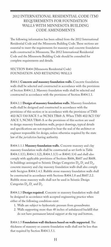
The following information has been edited from the 2012 International Residential Code and the Minnesota Building Code. These sections are essential to meet the requirements for masonry and concrete foundation walls constructed in Minnesota. The 2012 International Residential Code and the Minnesota Building Code should be consulted for complete requirements and details.
SECTION R404 (Minnesota Residential Code)FOUNDATION AND RETAINING WALLS
R404.1 Concrete and masonry foundation walls. Concrete foundation walls shall be selected and constructed in accordance with the provisions of Section R404.1.2. Masonry foundation walls shall be selected and constructed in accordance with the provisions of Section R404.1.1.
R404.1.1 Design of masonry foundation walls. Masonry foundation walls shall be designed and constructed in accordance with the provisions of this section or in accordance with the provisions of TMS 402/ACI 530/ASCE 5 or NCMA TR68-A. When TMS 402/ACI 530/ASCE 5, NCMA TR68-A or the provisions of this section are used to design masonry foundation walls, project drawings, typical details and specifications are not required to bear the seal of the architect or engineer responsible for design, unless otherwise required by the state law of the jurisdiction having authority.
R404.1.1.1 Masonry foundation walls. Concrete masonry and clay masonry foundation walls shall be constructed as set forth in Table R404.1.1(1), R404.1.1(2), R404.1.1(3) or R4041.1(4) and shall also comply with applicable provisions of Sections R606, R607 and R608. In buildings assisnged to Seismic Design Categories D0, D1 and D2, concrete masonry and clay masonry foundation walls shall also comply with Sectgion R404.1.4.1. Rubble stone masonry foundation walls shall be constructed in accordance with Sections R404.1.8 and R607.2.2. Rubble stone masonry walls shall not be used in Seismic Design Categories D0, D1 and D2. R404.1.3 Design required. Concrete or masonry foundation walls shall be designed in accordance with accepted engineering practice when either of the following conditions exist: 1. Walls are subject to hydrostatic pressure from groundwater. 2. Walls supporting more than 48 inches of unbalanced backfill that
do not have permanent lateral support at the top and bottom.
R404.1.5 Foundation wall thickness based on walls supported. The thickness of masonry or conrete foundation walls shall not be less than that required by Section R404.1.5.1.

I
R404.1.5.1 Masonry wall thickness. Masonry foundation walls shall not be less than the thickness of the wall supported, except that masonry foundation walls of at least 8-inch (203 mm) nominal thickness shall be permitted under brick veneered frame walls and under 10 inch-wide (254 mm) cavity walls where the total height of the wall supported, including gables, is not more than 20 feet (6096 mm), provided the requirements of Section R404.1.1 are met.
R404.1.6 Height above grade. Concrete and masonry foundation walls shall extend above the finished grade adjacent to the foundation at all points a minimum of 4 inches where masonry veneer is used and a minimum of 6 inches elsewhere.
R404.1.7 Backfill placement. Backfill shall not be placed against the wall until the wall has sufficient strength and has been anchored to the floor above, or has been sufficiently braced to prevent damage by the back fill.
Exception: bracing is not required for walls supporting less than 4 feet of unbalanced backfill.

J
TABLE 1PLAIN MASONRY FOUNDATION WALLS
[Based on the 2012 IRC table R404.1.1(1)]
Maximum Wall Height (feet)
Maximum Unbalanced
Backfill Height (feet)
Plain Masonry Minimum Nominal Wall Thickness (inches)
Soil Classes
GW, GP, SW, & GP
GM, CG, SM, SM-SC, &
ML
SC, MH, ML-CL, and Inorganic CL
54 6 solid or 8 6 solid or 8 6 solid or 8
5 6 solid or 8 8 10
6
4 6 solid or 8 6 solid or 8 6 solid or 8
5 6 solid or 8 8 10
6 8 10 12
7
4 6 solid or 8 8 8
5 6 solid or 8 10 10
6 10 12 10 solid
7 12 10 solid 12 solid
8
4 6 solid or 8 6 solid or 8 8
5 6 solid or 8 10 12
6 10 12 12 solid
7 12 12 solid Footnote e
8 10 solid 12 solid Footnote e
9
4 6 solid or 8 6 solid or 8 8
5 8 10 12
6 10 12 12 solid
7 12 12 solid Footnote e
8 12 solid Footnote e Footnote e
9 Footnote e Footnote e Footnote e
For SI: 1 inch = 25.4 mm, 1 foot = 304.8 mm, 1 pound per square inch - 6.895 Pa.
a. Mortar shall be Type M or S and masonry shall be laid in running bond. Ungrouted hollow masonry units are permitted except where otherwise indicated.
b. Soil classes are in accordance with the Unified Soil Classification System. Refer to Table R405.1
c. Unbalanced backfill height is the difference in height between the exterior finish ground level and the lower of the top of the concrete footing that supports the foundation wall or the interior finish ground level. Where an interior concrete slab-on-grade is provided and is in contact with the interior surface of the foundation wall, measurement of the unbalanced backfill height from the exterior finish ground level to the top of the interior concrete slab is permitted.
d. Solid grouted hollow units or solid masonry units.
e. Wall construction shall be in accordance with either Table R404.1.1(2), Table R404.1.1(3), Table R404.1.1(4), or a design shall be provided. When the maximum unbalanced backfill height exceeds 6 feet consider using reinforcement schedules from tables 2, 3, or 4. Variables in backfilling conditions and wall bracing may make wall reinforcement advisable under these conditions.
K
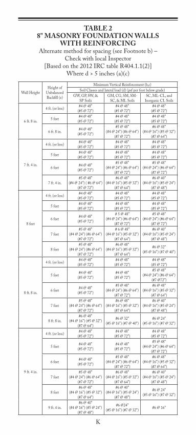
TABLE 28" MASONRY FOUNDATION WALLS
WITH REINFORCINGAlternate method for spacing (see Footnote b) –
Check with local Inspector[Based on the 2012 IRC table R404.1.1(2)]
Where d > 5 inches (a)(c)
Wall HeightHeight of
Unbalanced Backfill (e)
Minimum Vertical Reinforcement (b,c)Soil Classes and lateral load (d) (psf per foot below grade)
GW, GP, SW, & SP Soils
GM, CG, SM, SM-SC, & ML Soils
SC, ML-CL, and Inorganic CL Soils
6 ft. 8 in.
4 ft. (or less) #4 @ 48"(#5 @ 72")
#4 @ 48"(#5 @ 72")
#4 @ 48"(#5 @ 72")
5 feet #4 @ 48"(#5 @ 72")
#4 @ 48"(#5 @ 72")
#4 @ 48"(#5 @ 72")
6 ft. 8 in. #4 @ 48"(#5 @ 72")
#5 @ 48"(#4 @ 24") (#6 @ 64")
(#7 @ 72")
#6 @ 48"(#4 @ 16") (#5 @ 32")
(#7 @ 64")
7 ft. 4 in.
4 ft. (or less) #4 @ 48"(#5 @ 72")
#4 @ 48"(#5 @ 72")
#4 @ 48"(#5 @ 72")
5 feet #4 @ 48"(#5 @ 72")
#4 @ 48"(#5 @ 72")
#4 @ 48"(#5 @ 72")
6 feet #4 @ 48"(#5 @ 72")
#5 @ 48"(#4 @ 24") (#6 @ 64")
(#7 @ 72")
#5 @ 48"(#4 @ 24") (#6 @ 64")
(#7 @ 72")
7 ft. 4 in.#5 @ 48"
(#4 @ 24") ( #6 @ 64") (#7 @ 72")
#6 @ 48"(#4 @ 16") (#5 @ 32")
(#7 @ 64")
#6 @ 40"(#4 @ 16") (#5 @ 24")
(#7 @ 48")
8 feet
4 ft. (or less) #4 @ 48"(#5 @ 72")
#4 @ 48"(#5 @ 72")
#4 @ 48"(#5 @ 72")
5 feet #4 @ 48"(#5 @ 72")
#4 @ 48"(#5 @ 72")
#4 @ 48"(#5 @ 72")
6 feet #4 @ 48"(#5 @ 72")
# 5 @ 48"(#4 @ 24") (#6 @ 64")
(#7 @ 72")
#5 @ 48"(#4 @ 24") (#6 @ 64")
(#7 @ 72")
7 feet#5 @ 48"
(#4 @ 24") (#6 @ 64") (#7 @ 72")
# 6 @ 48"(#4 @ 16") (#5 @ 32")
(#7 @ 64")
#6 @ 40"(#4 @ 16") (#5 @ 24")
(#7 @ 48")
8 feet#5 @ 48"
(#4 @ 24") (#6 @ 64") (#7 @ 72")
#6 @ 48"(#4 @ 16") (#5 @ 32")
(#7 @ 64")
#6 @ 32"(#5 @ 16") (#7 @ 40")
8 ft. 8 in.
4 ft. (or less) #4 @ 48"(#5 @ 72")
#4 @ 48"(#5 @ 72")
#4 @ 48"(#5 @ 72")
5 feet #4 @ 48"(#5 @ 72")
#4 @ 48"(#5 @ 72")
#5 @ 48"(#4 @ 24") (#6 @ 64")
(#7 @72")
6 feet #4 @ 48"(#5 @ 72")
#5 @ 48"(#4 @ 24") (#6 @ 64")
(#7 @ 72")
#6 @ 48"(#4 @ 16") (#5 @ 32")
(#7 @ 64")
7 feet#5 @ 48"
(#4 @ 24") (#6 @ 64") (#7 @ 72")
#6 @ 48"(#4 @ 16") (#5 @ 32")
(#7 @ 64")
#6 @ 40"(#4 @ 16") (#5 @ 24")
(#7 @ 48")
8 ft. 8 in.#6 @ 48"
(#4 @ 16") (#5 @ 32") (#7 @ 64")
#6 @ 32"(#5 @ 16") (#7 @ 40")
#6 @ 24"(#5 @ 16") (#7 @ 32")
9 ft. 4 in.
4 ft. (or less) #4 @ 48"(#5 @ 72")
#4 @ 48"(#5 @ 72")
#4 @ 48"(#5 @ 72")
5 feet #4 @ 48"(#5 @ 72")
#4 @ 48"(#5 @ 72")
#5 @ 48"(#4 @ 24") (#6 @ 64")
(#7 @ 72")
6 feet #4 @ 48"(#5 @ 72")
#5 @ 48"(#4 @ 24") (#6 @ 64")
(#7 @ 72")
#6 @ 48"(#4 @ 16") (#5 @ 32")
(#7 @ 64")
7 feet#5 @ 48"
(#4 @ 24") (#6 @ 64") (#7 @ 72")
#6 @ 48"(#4 @ 16") (#5 @ 32")
(#7 @ 64")
#6 @ 40"(#4 @ 16") (#5 @ 24")
(#7 @ 48")
8 feet#6 @ 48"
(#4 @ 16") (#5 @ 32") (#7 @ 64")
#6 @ 40"(#4 @ 16") (#5 @ 24")
(#7 @ 48")
#6 @ 24"(#5 @ 16") (#7 @ 32")
9 ft. 4 in.#6 @ 40"
(#4 @ 16") (#5 @ 24") (#7 @ 48")
#6 @24"(#5 @ 16") (#7 @ 32") #6 @ 16"

L
10 feet
4 feet (or less) #4 @ 48"(#5 @ 72")
#4 @ 48"(#5 @ 72")
#4 @ 48"(#5 @ 72")
5 feet #4 @ 48"(#5 @ 72")
#4 @ 48"(#5 @ 72")
#5 @ 48"(#4 @ 24") (#6 @ 64")
(#7 @ 72")
6 feet #4 @ 48"(#5 @ 72")
#5 @ 48"(#4 @ 24") (#6 @ 64")
(#7 @ 72")
#6 @ 48"(#4 @ 16") (#5 @ 32")
(#7 @ 64")
7 feet#5 @ 48"
(#4 @ 24") (#6 @ 64") (#7 @ 72")
#6 @ 48"(#4 @ 16") (#5 @ 32")
(#7 @ 64")
#6 @ 32"(#5 @ 16") (#7 @ 40")
8 feet#6 @ 48"
(#4 @ 16") (#5 @ 32") (#7 @ 64")
#6 @ 32"(#5 @ 16") (#7 @ 40")
#6 @ 24"(#5 @ 16") (#7 @ 32")
9 feet#6 @ 40"
(#4 @ 16") (#5 @ 24") (#7 @ 48")
#6 @ 24"(#5 @ 16") (#7 @ 32") #6 @ 16"
10 feet #6 @ 32"(#5 @ 16") (#7 @ 40") #6 @ 16" #6 @ 16"
a. Mortar shall be Type M or S and masonry shall be laid in running bond.b. The first reinforcing bar size and spacing is as prescribed in the IRC tables and is followed by alternative
bar sizes and spacing having an equivalent cross-sectional area of reinforcement per lineal foot of wall as permitted, providing the spacing of the reinforcement does not exceed 72 inches.
c. Vertical reinforcement shall be Grade 60 minimum. The distance from the face of the soil side of the wall to the center of vertical reinforcement shall be at least 5 inches.
d. Soil classes are in accordance with the Unified Soil Classification System and design lateral soil loads are for moist conditions without hydrostatic pressure. Refer to Table 1.
e. Unbalanced backfill height is the difference in height of the exterior finish ground level and the lower of the top of the concrete footing that supports the foundation wall or the interior finish ground level. Where an interior concrete slab-on-grade is provided and is in contact with the interior surface of the foundation wall, measurement of the unbalanced backfill height from the exterior finish ground level to the top of the interior concrete slab is permitted.

M
TABLE 310" MASONRY FOUNDATION WALLS
WITH REINFORCINGAlternate method for spacing (see Footnote b) –
Check with local Inspector[Based on the 2012 IRC table R404.1.1(3)]
Where d > 6.75 inches (a)(c)
Wall HeightHeight of
Unbalanced Backfill (e)
Minimum Vertical Reinforcement (b,c)Soil Classes and lateral load (d) (psf per foot below grade)
GW, GP, SW, & SP Soils
GM, CG, SM, SM-SC, & ML Soils
SC, ML-CL, and Inorganic CL Soils
6 ft. 8 in.
4 ft. or less #4 @ 56"(#5 @ 72")
#4 @ 56"(#5 @ 72")
#4 @ 56"(#5 @ 72")
5 feet #4 @ 56"(#5 @ 72")
#4 @ 56"(#5 @ 72")
#4 @ 56"(#5 @ 72")
6 ft. 8 in. #4 @ 56"(#5 @ 72")
#5 @ 56"(#4 @ 32") (#6 @ 72")
#5 @ 56"(#4 @ 32") (#6 @ 72")
7 ft. 4 in.
4 ft. (or less) #4 @ 56"(#5 @ 72")
#4 @ 56"(#5 @ 72")
#4 @ 56"(#5 @ 72")
5 feet #4 @ 56"(#5 @ 72")
#4 @ 56"(#5 @ 72")
#4 @ 56"(#5 @ 72")
6 feet #4 @ 56"(#5 @ 72")
#4 @ 56"(#5 @ 72")
#5 @ 56"(#4 @ 32") (#6 @ 72")
7 ft. 4 in. #4 @ 56"(5 @ 72")
#5 @ 56"(#4 @ 32") (#6 @ 72")
#6 @ 56"(#4 @ 24") (#5 @ 32")
(#7 @ 72")
8 feet
4 ft. (or less) #4 @ 56"(#5 @ 72")
#4 @ 56"(#5 @ 72")
#4 @ 56"(#5 @ 72")
5 feet #4 @ 56"(#5 @ 72")
#4 @ 56"(#5 @ 72")
#4 @ 56"(#5 @ 72")
6 feet #4 @ 56"(#5 @ 72")
#4 @ 56"(#5 @ 72")
#5 @ 56"(#4 @ 32") (#6 @ 72")
7 feet #4 @ 56"(#5 @ 72")
#5 @ 56"(#4 @ 32") (#6 @ 72")
#6 @ 56"(#4 @ 24") (#5 @ 32")
(#7 @ 72")
8 feet #5 @ 56"(#4 @ 32") (#6 @ 72")
#6 @ 56"(#4 @ 24") (#5 @ 32")
(#7 @ 72")
#6 @ 48"(#4 @ 16") (#5 @ 32")
(#7 @ 64")
8 ft. 8 in.
4 ft. (or less) #4 @ 56"(#5 @ 72")
#4 @ 56"(#5 @ 72")
#4 @ 56"(#5 @ 72")
5 feet #4 @ 56"(#5 @ 72")
#4 @ 56"(#5 @ 72")
#4 @ 56"(#5 @ 72")
6 feet #4 @ 56"(#5 @ 72")
#4 @ 56"(#5 @ 72")
#5 @ 56"(#4 @ 32") (#6 @ 72")
7 feet #4 @ 56"(#5 @ 72")
#5 @ 56"(#4 @ 32") (#6 @ 72")
#6 @ 56"(#4 @ 24") (#5 @ 32")
(#7 @ 72")
8 ft. 8 in. #5 @ 56"(#4 @ 32") (#6 @ 72")
#6 @ 48"(#4 @ 16") (#5 @ 32")
(#7 @ 64")
#6 @ 32"(#5 @ 16") (#7 @ 40")
9 ft. 4 in.
4 ft. (or less) #4 @ 56"(#5 @ 72")
#4 @ 56"(#5 @ 72")
#4 @ 56"(#5 @ 72")
5 feet #4 @ 56"(#5 @ 72")
#4 @ 56"(#5 @ 72")
#4 @ 56"(#5 @ 72")
6 feet #4 @ 56"(#5 @ 72")
#5 @ 56"(#4 @ 32") (#6 @ 72")
#5 @ 56"(#4 @ 32") (#6 @ 72")
7 feet #4 @ 56"(#5 @ 72")
#5 @ 56"(#4 @ 32") (#6 @ 72")
#6 @ 56"(#4 @ 24") (#5 @ 32")
(#7 @ 72")
8 feet #5 @ 56"(#4 @ 32") (#6 @ 72")
#6 @ 56"(#4 @ 24") (#5 @ 32")
(#7 @ 72")
#6 @ 40"(#4 @ 16") (#5 @ 24")
(#7 @ 48")
9 ft. 4 in.#6 @ 56"
(#4 @ 24") (#5 @ 32") (#7 @ 72")
#6 @40"(#4 @ 16") (#5 @ 24")
(#7 @ 48")
#6 @ 24"(# 5 @ 16") (#7 @ 32")

N
10 feet
4 feet (or less) #4 @ 56"(#5 @ 72")
#4 @ 56"(#5 @ 72")
#4 @ 56"(#5 @ 72")
5 feet #4 @ 56"(#5 @ 72")
#4 @ 56"(#5 @ 72")
#4 @ 56"(#5 @ 72")
6 feet #4 @ 56"(#5 @ 72")
#5 @ 56"(#4 @ 32") (#6 @ 72")
#5 @ 56"(#4 @ 32") (#6 @ 72")
7 feet #5 @ 56"(#4 @ 32") (#6 @ 72")
#6 @ 56"(#4 @ 24") (#5 @ 32")
(#7 @ 72")
#6 @ 48"(#4 @ 16") (#5 @ 32")
(#7 @ 64")
8 feet #5 @ 56"(#4 @ 32") (#6 @ 72")
#6 @ 48"(#4 @ 16") (#5 @ 32")
(#7 @ 64")
#6 @ 40"(#4 @ 16") (#5 @ 24")
(#7 @ 48")
9 feet#6 @ 56"
(#4 @ 24") (#5 @ 32") (#7 @ 72")
#6 @ 40"(#4 @ 16") (#5 @ 24")
(#7 @ 48")
#6 @ 24"(#5 @ 16") (#7 @ 32")
10 feet#6 @ 48"
(#4 @ 16") (#5 @ 32") (#7 @ 64")
#6 @ 32"(#5 @ 16") (#7 @ 40")
#6 @ 24"(#5 @ 16") (#7 @ 32")
a. Mortar shall be Type M or S and masonry shall be laid in running bond.b. The first reinforcing bar size and spacing is as prescribed in the IRC tables and is followed by alternative
bar sizes and spacing having an equivalent cross-sectional area of reinforcement per lineal foot of wall as permitted, providing the spacing of the reinforcement does not exceed 72 inches.
c. Vertical reinforcement shall be Grade 60 minimum. The distance from the face of the soil side of the wall to the center of vertical reinforcement shall be at least 6.75 inches.
d. Soil classes are in accordance with the Unified Soil Classification System and design lateral soil loads are for moist conditions without hydrostatic pressure. See Table R405.1
e. Unbalanced backfill height is the difference in height of the exterior finish ground level and the lower of the top of the concrete footing that supports the foundation wall or the interior finish ground level. Where an interior concrete slab-on-grade is provided and is in contact with the interior surface of the foundation wall, measurement of the unbalanced backfill height from the exterior finish ground level to the top of the interior concrete slab is permitted.

O
TABLE 412" MASONRY FOUNDATION WALLS
WITH REINFORCINGAlternate method for spacing (see Footnote b) –
Check with local Inspector[Based on the 2012 IRC table R404.1.1(4)]
Where d > 8.75 inches (a)(c)
Wall HeightHeight of
Unbalanced Backfill (e)
Minimum Vertical Reinforcement (b,c)Soil Classes and lateral load (d) (psf per foot below grade)
GW, GP, SW, & SP Soils
GM, CG, SM, SM-SC, & ML Soils
SC, ML-CL, and Inorganic CL Soils
6 ft. 8 in.
4 ft. or less #4 @ 72" #4 @ 72" #4 @ 72")5 feet #4 @ 72" #4 @ 72" #4 @ 72"
6 ft. 8 in. #4 @ 72" #4 @ 72" #5 @ 72"(#4 @ 40")
7 ft. 4 in.
4 ft. (or less) #4 @ 72" #4 @ 72" #4 @ 72"5 feet #4 @ 72" #4 @ 72" #4 @ 72"
6 feet #4 @ 72" #4 @ 72" #5 @ 72"(#4 @ 40")
7 ft. 4 in. #4 @ 72" #5 @ 72"(#4 @ 40")
#6 @ 72"(#4 @ 32") (#5 @ 48")
8 feet
4 ft. (or less) #4 @ 72" #4 @ 72" #4 @ 72"5 feet #4 @ 72" #4 @ 72" #4 @ 72"
6 feet #4 @ 72" #4 @ 72" #5 @ 72"(#4 @ 40")
7 feet #4 @ 72" #5 @ 72"(#4 @ 40")
#6 @ 72"(#4 @ 32") (#5 @ 48")
8 feet #5 @ 72"(#4 @ 40")
#6 @ 72"(#4 @ 32") (#5 @ 48")
#6 @ 64"(#4 @ 24") (#5 @ 40")
(#7 @ 72")
8 ft. 8 in.
4 ft. (or less) #4 @ 72" #4 @ 72" #4 @ 72"5 feet #4 @ 72" #4 @ 72" #4 @ 72"
6 feet #4 @ 72" #4 @ 72" #5 @ 72"(#4 @ 40")
7 feet #4 @ 72" #5 @ 72"(#4 @ 40")
#6 @ 72"(#4 @ 32") (#5 @ 48")
8 ft. 8 in. #5 @ 72"(#4 @ 40")
#7 @ 72"(#4 @ 24") (#5 @ 32")
(#6 @ 48")
#6 @ 48"(#4 @ 16") (#5 @ 32")
(#7 @ 64")
9 ft. 4 in.
4 ft. (or less) #4 @ 72" #4 @ 72" #4 @ 72"5 feet #4 @ 72" #4 @ 72" #4 @ 72"
6 feet #4 @ 72" #5 @ 72"(#4 @ 40")
#5 @ 72"(#4 @ 40")
7 feet #4 @ 72" #5 @ 72"(#4 @ 40")
#6 @ 72"(#4 @ 32") (#5 @ 48")
8 feet #5 @ 72"(#4 @ 40")
#6 @ 72"(#4 @ 32") (#5 @ 48")
#6 @ 56"(#4 @ 24") (#5 @ 32")
(#7 @ 72")
9 ft. 4 in. #6 @ 72"(#4 @ 32") (#5 @ 48")
#6 @48"(#4 @ 16") (#5 @ 32")
(#7 @ 64")
#6 @ 40"(#4 @ 16") (#5 @ 24")
(#7 @ 48")
10 feet
4 feet (or less) #4 @ 72" #4 @ 72" #4 @ 72"5 feet #4 @ 72" #4 @ 72" #4 @ 72"
6 feet #4 @ 72" #5 @ 72"(#4 @ 40")
#5 @ 72"(#4 @ 40")
7 feet #4 @ 72" #6 @ 72"(#4 @ 32") (#5 @ 48")
#6 @ 72"(#4 @ 32") (#5 @ 48")
8 feet #5 @ 72"(#4 @ 40")
#6 @ 72"(#4 @ 32") (#5 @ 48")
#6 @ 48"(#4 @ 16") (#5 @ 32")
(#7 @ 64")
9 feet #6 @ 72"(#4 @ 32") (#5 @ 48")
#6 @ 56"(#4 @ 24") (#5 @ 32")
(#7 @ 72")
#6 @ 40"(#4 @ 16") (#5 @ 24")
(#7 @ 48")
10 feet#6 @ 64"
(#4 @ 24) (#5 @ 40") (#7 @ 72")
#6 @ 40"(#4 @ 16") (#5 @ 24")
(#7 @ 48")
#6 @ 32"(#5 @ 16") (#7 @ 40")
a. Mortar shall be Type M or S and masonry shall be laid in running bond.b. The first reinforcing bar size and spacing is as prescribed in the IRC tables and is followed by alternative
bar sizes and spacing having an equivalent cross-sectional area of reinforcement per lineal foot of wall as permitted, providing the spacing of the reinforcement does not exceed 72 inches.

P
c. Vertical reinforcement shall be Grade 60 minimum. The distance from the face of the soil side of the wall to the center of vertical reinforcement shall be at least 8.75 inches.
d. Soil classes are in accordance with the Unified Soil Classification System and design lateral soil loads are for moist conditions without hydrostatic pressure. See Table R405.1
e. Unbalanced backfill height is the difference in height of the exterior finish ground level and the lower of the top of the concrete footing that supports the foundation wall or the interior finish ground level. Where an interior concrete slab-on-grade is provided and is in contact with the interior surface of the foundation wall, measurement of the unbalanced backfill height from the exterior finish ground level to the top of the interior concrete slab is permitted.
Q
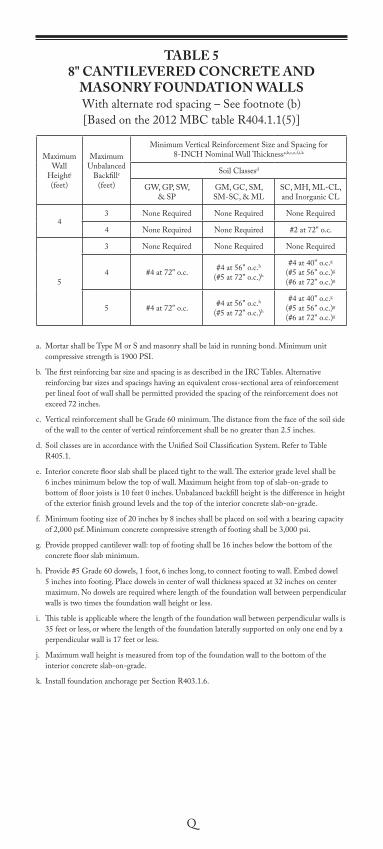
TABLE 58" CANTILEVERED CONCRETE AND
MASONRY FOUNDATION WALLSWith alternate rod spacing – See footnote (b)[Based on the 2012 MBC table R404.1.1(5)]
Maximum Wall
Heightj (feet)
Maximum Unbalanced
Backfille (feet)
Minimum Vertical Reinforcement Size and Spacing for 8-INCH Nominal Wall Thicknessa,b,c,e,f,i,k
Soil Classesd
GW, GP, SW, & SP
GM, GC, SM, SM-SC, & ML
SC, MH, ML-CL, and Inorganic CL
43 None Required None Required None Required
4 None Required None Required #2 at 72" o.c.
5
3 None Required None Required None Required
4 #4 at 72" o.c. #4 at 56" o.c.h
(#5 at 72" o.c.)h
#4 at 40" o.c.g
(#5 at 56" o.c.)g
(#6 at 72" o.c.)g
5 #4 at 72" o.c. #4 at 56" o.c.h
(#5 at 72" o.c.)h
#4 at 40" o.c.g
(#5 at 56" o.c.)g
(#6 at 72" o.c.)g
a. Mortar shall be Type M or S and masonry shall be laid in running bond. Minimum unit compressive strength is 1900 PSI.
b. The first reinforcing bar size and spacing is as described in the IRC Tables. Alternative reinforcing bar sizes and spacings having an equivalent cross-sectional area of reinforcement per lineal foot of wall shall be permitted provided the spacing of the reinforcement does not exceed 72 inches.
c. Vertical reinforcement shall be Grade 60 minimum. The distance from the face of the soil side of the wall to the center of vertical reinforcement shall be no greater than 2.5 inches.
d. Soil classes are in accordance with the Unified Soil Classification System. Refer to Table R405.1.
e. Interior concrete floor slab shall be placed tight to the wall. The exterior grade level shall be 6 inches minimum below the top of wall. Maximum height from top of slab-on-grade to bottom of floor joists is 10 feet 0 inches. Unbalanced backfill height is the difference in height of the exterior finish ground levels and the top of the interior concrete slab-on-grade.
f. Minimum footing size of 20 inches by 8 inches shall be placed on soil with a bearing capacity of 2,000 psf. Minimum concrete compressive strength of footing shall be 3,000 psi.
g. Provide propped cantilever wall: top of footing shall be 16 inches below the bottom of the concrete floor slab minimum.
h. Provide #5 Grade 60 dowels, 1 foot, 6 inches long, to connect footing to wall. Embed dowel 5 inches into footing. Place dowels in center of wall thickness spaced at 32 inches on center maximum. No dowels are required where length of the foundation wall between perpendicular walls is two times the foundation wall height or less.
i. This table is applicable where the length of the foundation wall between perpendicular walls is 35 feet or less, or where the length of the foundation laterally supported on only one end by a perpendicular wall is 17 feet or less.
j. Maximum wall height is measured from top of the foundation wall to the bottom of the interior concrete slab-on-grade.
k. Install foundation anchorage per Section R403.1.6.

R
TABLE 610" CANTILEVERED CONCRETE AND
MASONRY FOUNDATION WALLSWith alternate rod spacing – See footnote (b)[Based on the 2012 MBC table R404.1.1(6)]
Maximum Wall
Heightj (feet)
Maximum Unbalanced
Backfille (feet)
Minimum Vertical Reinforcement Size and Spacing for 10-INCH Nominal Wall Thicknessa,b,c,e,f,i,k
Soil Classesd
GW, GP, SW, & SP
GM, GC, SM, SM-SC, & ML
SC, MH, ML-CL, and Inorganic CL
43 None Required None Required None Required
4 None Required None Required None Required
5
3 None Required None Required None Required
4 None Required #4 at 72" o.c. #4 at 64" o.c.g
(#5 at 72" o.c.)g
5 #4 at 72" o.c. #4 at 72" o.c. #4 at 56" o.c.g
(#5 at 72" o.c.)g
6
3 None Required #4 at 72" o.c. #4 at 72" o.c.
4 #4 at 72" o.c. #4 at 72" o.c. #4 at 64" o.c.h
(#5 at 72" o.c.)h
5 #4 at 64" o.c.h
(#5 at 72" o.c.)h
#4 at 40" o.c.g,h
(#5 at 56" o.c.)g,h
(#6 at 72" o.c.)g,h
#5 at 48" o.c.g,h
(#6 at 64" o.c.)g,h
(#7 at 72" o.c.)g,h
6 #4 at 64" o.c.h
(#5 at 72" o.c.)h
#4 at 40" o.c.g,h
(#5 at 56" o.c.)g,h
(#6 at 72" o.c.)g,h
#5 at 48" o.c.g,h
(#6 at 64" o.c.)g,h
(#7 at 72" o.c.)g,h
a. Mortar shall be Type M or S and masonry shall be laid in running bond. Minimum unit compressive strength is 1900 PSI.
b. The first reinforcing bar size and spacing is as described in the IRC Tables. Alternative reinforcing bar sizes and spacings having an equivalent cross-sectional area of reinforcement per lineal foot of wall shall be permitted provided the spacing of the reinforcement does not exceed 72 inches.
c. Vertical reinforcement shall be Grade 60 minimum. The distance from the face of the soil side of the wall to the center of vertical reinforcement shall be no greater than 2.5 inches.
d. Soil classes are in accordance with the Unified Soil Classification System. Refer to Table R405.1.
e. Interior concrete floor slab shall be placed tight to the wall. The exterior grade level shall be 6 inches minimum below the top of wall. Maximum height from top of slab-on-grade to bottom of floor joists is 10 feet 0 inches. Unbalanced backfill height is the difference in height of the exterior finish ground levels and the top of the interior concrete slab-on-grade.
f. Minimum footing size of 20 inches by 8 inches shall be placed on soil with a bearing capacity of 2,000 psf. Minimum concrete compressive strength of footing shall be 3,000 psi.
g. Provide propped cantilever wall: top of footing shall be 16 inches below the bottom of the concrete floor slab minimum.
h. Provide #5 Grade 60 dowels, 1 foot, 6 inches long, to connect footing to wall. Embed dowel 5 inches into footing. Place dowels in center of wall thickness spaced at 32 inches on center maximum. No dowels are required where length of the foundation wall between perpendicular walls is two times the foundation wall height or less.
i. This table is applicable where the length of the foundation wall between perpendicular walls is 35 feet or less, or where the length of the foundation laterally supported on only one end by a perpendicular wall is 17 feet or less.
j. Maximum wall height is measured from top of the foundation wall to the bottom of the interior concrete slab-on-grade.
k. Install foundation anchorage per Section R403.1.6.

S
TABLE 712" CANTILEVERED CONCRETE AND
MASONRY FOUNDATION WALLSWith alternate rod spacing– See footnote (b)[Based on the 2012 MBC table R404.1.1(7)]
Maximum Wall
Heightj (feet)
Maximum Unbalanced
Backfille (feet)
Minimum Vertical Reinforcement Size and Spacing for 12-INCH Nominal Wall Thicknessa,b,c,e,f,i,k
Soil Classesd
GW, GP, SW, & SP
GM, GC, SM, SM-SC, & ML
SC, MH, ML-CL, and Inorganic CL
43 None Required None Required None Required
4 None Required None Required None Required
5
3 None Required None Required None Required
4 None Required None Required #4 @ 72" o.c.
5 #4 at 72" o.c. #4 at 72" o.c. #4 at 72" o.c.
6
3 None Required None Required None Required
4 None Required None Required #4 at 72" o.c.
5 #4 at 64" o.c.h #4 at 56" o.c.h
(#5 at 72" o.c.)h
#4 at 40" o.c.g
(#5 at 56" o.c.)g
(#6 at 72" o.c.)g
6 #4 at 72" o.c. #4 at 56" o.c.g
(#5 at 72" o.c.)g
#4 at 32" o.c.g,h
(#5 at 48" o.c.)g,h
(#6 at 72" o.c.)g,h
(#7 at 64" o.c.)g,h
7
3 None Required None Required None Required
4 None Required #4 at 72" o.c. #4 at 72" o.c.
5 #4 at 72" o.c. #4 at 56" o.c.h
(#5 at 72" o.c.)h
#4 at 40" o.c.g
(#5 at 56" o.c.)g
(#6 at 72" o.c.)g
6 #4 at 48" o.c.(#5 at 72" o.c.)
#5 at 48" o.c.g,h
(#6 at 64" o.c.)g,h
(#7 at 72" o.c.)g,h
#6 at 48" o.c.g,h
(#7 at 64" o.c.)g,h
7 #4 at 48" o.c.h
(#5 at 72" o.c.)h
#4 at 40" o.c.g,h
(#5 at 56" o.c.)g,h
(#6 at 72" o.c.)g,h
#6 at 48" o.c.g,h
(#7 at 64" o.c.)g,h
a. Mortar shall be Type M or S and masonry shall be laid in running bond. Minimum unit compressive strength is 1900 PSI.
b. The first reinforcing bar size and spacing is as described in the IRC Tables. Alternative reinforcing bar sizes and spacings having an equivalent cross-sectional area of reinforcement per lineal foot of wall shall be permitted provided the spacing of the reinforcement does not exceed 72 inches.
c. Vertical reinforcement shall be Grade 60 minimum. The distance from the face of the soil side of the wall to the center of vertical reinforcement shall be no greater than 2.5 inches.
d. Soil classes are in accordance with the Unified Soil Classification System. Refer to Table R405.1.
e. Interior concrete floor slab shall be placed tight to the wall. The exterior grade level shall be 6 inches minimum below the top of wall. Maximum height from top of slab-on-grade to bottom of floor joists is 10 feet 0 inches. Unbalanced backfill height is the difference in height of the exterior finish ground levels and the top of the interior concrete slab-on-grade.
f. Minimum footing size of 20 inches by 8 inches shall be placed on soil with a bearing capacity of 2,000 psf. Minimum concrete compressive strength of footing shall be 3,000 psi.
g. Provide propped cantilever wall: top of footing shall be 16 inches below the bottom of the concrete floor slab minimum.

T
h. Provide #5 Grade 60 dowels, 1 foot, 6 inches long, to connect footing to wall. Embed dowel 5 inches into footing. Place dowels in center of wall thickness spaced at 32 inches on center maximum. No dowels are required where length of the foundation wall between perpendicular walls is two times the foundation wall height or less.
i. This table is applicable where the length of the foundation wall between perpendicular walls is 35 feet or less, or where the length of the foundation laterally supported on only one end by a perpendicular wall is 17 feet or less.
j. Maximum wall height is measured from top of the foundation wall to the bottom of the interior concrete slab-on-grade.
k. Install foundation anchorage per Section R403.1.6.

U
Recommended One & TwoFamily Residential ColdWeather MasonryConstruction Guidelines
A part of the Recommended Practices Manual, 6th ed.
2.1
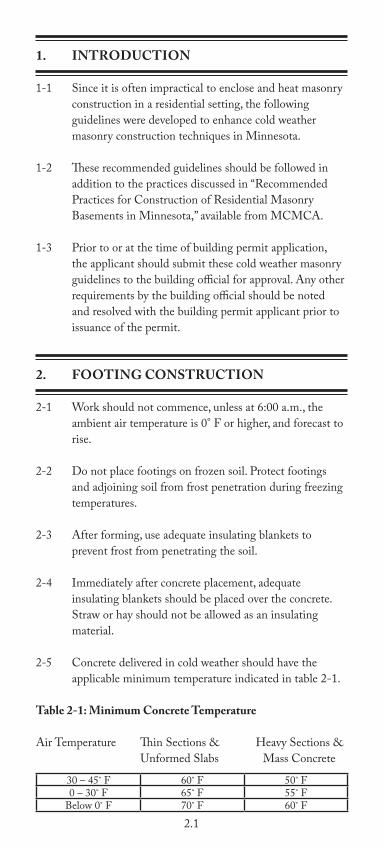
1. INTRODUCTION
1-1 Since it is often impractical to enclose and heat masonry construction in a residential setting, the following guidelines were developed to enhance cold weather masonry construction techniques in Minnesota.
1-2 These recommended guidelines should be followed in addition to the practices discussed in “Recommended Practices for Construction of Residential Masonry Basements in Minnesota,” available from MCMCA.
1-3 Prior to or at the time of building permit application, the applicant should submit these cold weather masonry guidelines to the building official for approval. Any other requirements by the building official should be noted and resolved with the building permit applicant prior to issuance of the permit.
2. FOOTING CONSTRUCTION
2-1 Work should not commence, unless at 6:00 a.m., the ambient air temperature is 0° F or higher, and forecast to rise.
2-2 Do not place footings on frozen soil. Protect footings and adjoining soil from frost penetration during freezing temperatures.
2-3 After forming, use adequate insulating blankets to prevent frost from penetrating the soil.
2-4 Immediately after concrete placement, adequate insulating blankets should be placed over the concrete. Straw or hay should not be allowed as an insulating material.
2-5 Concrete delivered in cold weather should have the applicable minimum temperature indicated in table 2-1.
Table 2-1: Minimum Concrete Temperature
Air Temperature Thin Sections & Heavy Sections & Unformed Slabs Mass Concrete
30 – 45˚ F 60˚ F 50˚ F0 – 30˚ F 65˚ F 55˚ F
Below 0˚ F 70˚ F 60˚ F

2.2
The maximum temperature of concrete produced with heated aggregates, heated water, or both, should at no time during its production or transportation exceed 90° F. Note: The temperature of the concrete produced during hot weather should be as low as practical.
3. MASONRY MATERIALS
3-1 Masonry materials (Concrete Block, Brick or Stone) stored on the job should be covered and kept dry.
3-2 All masonry laid should be free from ice and snow.
3-3 When ambient temperatures are 25° F or lower, all walls after construction should be covered with wind-resistant material, on both sides, from the top of the wall down to the footings.
4. MORTAR AND GROUT
4-1 The following recommendations should be met for the following temperatures.
• Temperatures 40°F - 32°F Construction Requirements: Heat materials to produce mortar or grout between 40°F - 120°F (4°C - 49°C).
• Temperatures 32°F and below Construction Requirements: Heat materials to produce mortar or grout between 40°F - 120°F (4°C - 49°C). Maintain mortar or grout above freezing until used in masonry.
4-2 Additional Comments
a. In cold weather conditions, accelerating the initial set time of mortar or grout materials may be desired. Use one of these methods:
a. Type III may be used in place of Type I for faster initial set time and faster initial strength gain.
b. Set accelerated pre-blended mortar may be used for faster initial set time and faster initial strength gain.
c. A liquid set accelerator may be added to mortar or grout for faster initial set time

2.3
and faster initial strength gain.
b. Mortar should be mixed in smaller amounts so it can be used before it cools.
c. Every effort should be made to produce consecutive batches of mortar with consistent temperatures.
d. Cover walls with wind-resistant materials to prevent rapid heat loss or water from entering masonry.
References:
1. “Recommended One and Two Family Cold Weather Masonry Construction Guidelines”, Minnesota Codes and Fire Safety Council, 1993.
2. “Cold Weather Concrete and Masonry,” http://www.dli.mn.gov/CCLD/OpinionDivisionBuildCold.asp.
Tables
Table 2-1 Minimum Concrete Temperatures
Diagrams
Minnesota Frost Depth Map
Mortar Cards
1) Mortar Cement and Masonry Cement
2) Portland Cement and Lime

1
RecommendedRadon Guidelines
A part of the Recommended Practices Manual, 6th ed.

NOTES

3.1
INTRODUCTION
As of June 1, 2009, all new houses built in Minnesota are required to include features designed to resist or reduce the infiltration of radon gas. Radon, an odorless, tasteless gas that forms from the decay of naturally occurring uranium found in rock and soil throughout Minnesota, is the second leading cause of lung cancer in the U.S. The Minnesota state building code requires builders to install a “passive” radon mitigation system that does not include a powered exhaust fan. These systems reduce soil gas entry points and provide a route to vent the gases to the outdoors.
New additions to an existing house that already has a radon system will need a radon control system. For more information on the health risks associated with radon, visit www.health.state.mn.us/radon. For more information on Minnesota building codes related to radon, contact Don Sivigny, MN Department of Labor & Industry, at 651-284-5874 or e-mail [email protected].
2015 MN STATE RADON REQUIREMENTS 1303.2400-1303.2403 INCORPORATION BY REFERENCE
1303.2401 DEFINITIONS
Subp. 2. Definitions. For the purposes of parts 1303.2400 to 1303.2403, the terms defined in this part have the meanings given them.
ACTIVE RADON CONTROL SYSTEM. “Active radon control system” means a system designed to achieve lower air pressure below the soil-gas membrane relative to the indoor air pressure by use of a fan that has been added to the passive radon control system.
APPROVED. “Approved” means approval by the building official, pursuant to the Minnesota State Building Code, by reason of inspection, investigation, or testing; accepted principles; computer simulations; research reports; or testing performed by either a licensed engineer or by a locally or nationally recognized testing laboratory.

3.2
GAS PERMEABLE MATERIAL. A “gas permeable material” means any of the following:
1. A uniform layer of clean aggregate, a minimum of 4 inches (102 mm) thick. The aggregate shall consist of materials that will pass through a 2-inch (51 mm) sieve and be retained by a 1/4 inch (6.4 mm) sieve.
2. A uniform layer of sand, native or fill, a minimum of 4 inches (102 mm) thick, overlain by a layer or strips of geotextile drainage matting designed to allow the lateral flow of soil gases.
3. Other materials, systems, or floor designs if material, system, or floor design is professionally engineered to provide depressurization under the entire soil-gas membrane.
PASSIVE RADON CONTROL SYSTEM. “Passive radon control system” means a system designed to achieve lower air pressure below the soil-gas membrane relative to the indoor air pressure by use of a vent pipe that relies on stack effect to provide an upward flow of air from beneath the soil-gas membrane.
RADON GAS. A naturally occurring, chemically inert, radioactive gas that is not detectable by human senses. As a gas, it can move readily through particles of soil and rock and can accumulate under the slabs and foundations of homes where it can easily enter into the living space through construction cracks and openings.
SEALED: “Sealed” means to prevent the movement of air or airborne gases through a floor, wall, or ceiling assembly.
SOIL-GAS MEMBRANE. “Soil-gas membrane: means a continuous membrane of 6-mil (0.15 mm) polyethylene, 3-mil (0.075 mm) cross-laminated polyethylene.
VENT PIPE. “Vent pipe” means a 3-inch (76 mm) or 4-inch (102 mm) diameter ABS or PVC pipe used to vent subsoil gases that have collected under the soil-gas membrane to the exterior of the dwelling.
1303.2402 REQUIREMENTS FOR PASSIVE
RADON CONTROL SYSTEMS
Subpart 1. Gas permeable material preparation. A gas-permeable material shall be placed on the prepared subgrade under all floor systems.
3.3
Subp. 2. Soil-gas membrane installation. A soil-gas membrane shall be placed on top of the gas-permeable material prior to placing a floor on top of or above the soil. The soil-gas membrane shall cover the entire floor area. Separate sections of membrane must be lapped at least 12 inches (305 mm). The membrane shall fit closely around any penetration of the membrane to reduce the leakage of soil gases. All punctures or tears in the soil-gas membrane shall be repaired by sealing and patching the soil-gas membrane with the same kind of material, maintaining a minimum 12-inch (305 mm) lap.
Subp. 3. “T” fitting. A “T” fitting shall be installed beneath the soil-gas membrane with a minimum of 10 feet of perforated pipe connect to any two openings of the “T” fitting, or by connecting the two openings to the interior drain tile system. The third opening of the “T” fitting shall be connected to the vent pipe. The perforated pipe or drain tile and the “T” fitting shall be the same size as the vent pipe. All connections to the “T” fitting shall be tight fitting.
Subp. 4. Potential entry routes. Potential entry routes for radon gas shall be sealed according to this subpart, as applicable.
A. Floor openings. Floor openings around bathtubs, showers, water closets, pipes, wires, or other objects that penetrate the soil-gas membrane and the concrete slab or other floor systems, shall be sealed.
B. Concrete joints. All control joints, isolation joints, construction joints, or any other joints in the concrete slab, or the joint between the concrete slab and a foundation wall, shall be sealed. All gaps and joints shall be cleared of all loose material prior to sealing.
C. Foundation walls. Penetrations of all foundation wall types shall be sealed. Joints, cracks, or other openings around all penetrations of both exterior and interior surfaces of foundation walls shall be sealed.
(1) Hollow block masonry foundation walls shall be constructed with either:
(a) continuous course of solid masonry at or above the exterior ground surface;
(b) one course of masonry grouted solid at or above the exterior ground surface; or
(c) a solid concrete beam at or above the finished exterior ground surface.
(2) When a brick veneer or other masonry ledge is installed, the masonry course immediately below the veneer or ledge shall be solid or filled.

3.4
D. Unconditioned crawl spaces. All penetrations through floors or walls into unconditioned crawl spaces shall be sealed. Access doors into unconditioned crawl spaces shall be gasketed. Crawl space ventilation shall be provided according to part 1303.2400.
E. Sumps. A sump connected to interior drain tile may serve as the termination point for the vent pipe, if the sump cover is sealed or gasketed and designed to accommodate the vent pipe. The sump pump water discharge pipe shall have a backflow preventer installed.
Subp. 5. Vent pipes.
A. Single vent pipe. The vent pipe shall be primed and glued at all fittings and shall extend up from the radon control system’s collection point to a point terminating a minimum of 12 inches (305 mm) above the roof. The vent pipe shall be located at least 10 feet (3048 mm) away from any window or other opening into the conditioned spaces of the building. Vent pipes routed through unconditioned spaces shall be insulated with a minimum of R-4 insulation. Vent pipes within the conditioned envelope of the building shall not be insulated.
B. Multiple vent pipes. In buildings where interior footings or other barriers separate the gas-permeable material into two or more areas, each area shall be fitted with an individual radon control system in accordance with item A, or connected to a single radon gas vent pipe terminating above the roof in accordance with item A.
C. Vent pipe drainage. All components of the radon gas vent pipe system shall be installed to provide drainage to the ground beneath the soil-gas membrane.
D. Vent pipe accessibility. Radon gas vent pipes shall be provided with space around the vent pipe for future installation of a fan. The space required for the future fan installation shall be a minimum of 24 inches (610 mm) in diameter, centered on the axis of the vent pipe, and shall extend a minimum distance of 3 vertical feet (914 mm).
Exception: Accessibility to the radon gas vent pipe is not required if the future fan installation is above the roof system and there is an approved rooftop electrical supply provided.
E. Vent pipe identification. All radon gas vent pipes shall be identified with at least 1 label on each story and in attics and crawl spaces. The label shall read: “Radon Gas Vent System.”

3.5
F. Combination foundations. Combination basement/crawl space or slab-on grade/crawl space foundations shall have separate radon gas vent pipes installed in each type of foundation area. Each radon gas vent pipe shall terminate above the roof or shall be connected to a single vent pipe that terminates above the roof.
Subp. 6. Power source. A power source consisting of an electrical circuit terminating in an approved electrical box shall be installed during construction in the anticipated location of the vent pipe fan to allow for the future installation of a fan into a passive radon control system to make the system an active radon control system. The power source shall not be installed in any conditioned space, basement, or crawl space.
1303.2403 REQUIREMENTS FOR ACTIVE RADON CONTROL SYSTEMS
When an active radon control system is installed, all the requirements for the passive radon control system in parts 1303.2400 to 1303.2402 shall be met. In addition, an active radon control system shall incorporate items A to C in this part.
A. Radon gas vent pipe. A radon gas vent pipe fan manufactured for radon control systems and rated for continuous operation that provides a minimum measurement of 50 cubic feet (1.4158 m3) per minute at 1/2 inch (12.7 mm) water column shall be installed in the vertical vent pipe. The fan shall be attached to a radon gas vent pipe that connects the air below the soil-gas membrane with outdoor air and relies on the fan to provide upward air flow in the vent pipe. The radon gas vent pipe fan shall be installed outdoors, in attics, or in garages. The radon gas vent pipe fan shall not be installed in conditioned spaces of a building, basement, or crawl space. The radon gas vent pipe fan shall not be located where it positively pressurizes any portion of the vent pipe that is located inside conditioned space.
B. System monitoring device. An audible alarm, a manometer, or other similar device shall be installed to indicate when the fan is not operating.
C. Luminaire and receptacle outlet. A switch-controlled luminaire and the receptacle outlet near the fan shall be installed according to the Minnesota Electrical Code. The requirements of the International Mechanical Code, Section 306, do not apply.

3.6
TYPICAL SUB-SLAB DEPRESSURIZATIONPASSIVE RADON SYSTEM
ATTIC SEE SUBP. 5VENT PIPES (D)AND SUBP. 6POWER SOURCE(pgs 3.4 & 3.5)
LIVING AREA
BASEMENT
SLAB
DRAIN TILE LOOP
POLYETHYLENESHEETING
GRADEGRAVEL
PASSIVE RADON SYSTEM USINGDRAIN-TILE LOOP
RADON-RESISTANT CONSTRUCTION DETAILS FORFOUR FOUNDATION TYPES
SEE SUBP. 5VENT PIPES (D)AND SUBP. 6POWERSOURCE(pgs 3.4 & 3.5)
ATTIC
LIVING AREA
BASEMENT
SLAB POLYETHYLENESHEETING
DRAIN TILE LOOP
GRADEGRAVEL

3.7
PASSIVE RADON SYSTEM VENTEDTHROUGH SUMP
SUB-MEMBRANE DEPRESSURIZATION SYSTEMFOR CRAWL SPACE
ATTIC
LIVING AREA
BASEMENT
SLABPOLYETHYLENESHEETING
SUMP PIT
SUMPCOVER
GRADEGRAVEL
ATTIC
LIVING AREA
CRAWL SPACE
POLYETHYLENESHEETING
PERFORATEDDRAIN TILEGRADE
GRAVEL
SEE SUBP. 5VENT PIPES (D)AND SUBP. 6POWER SOURCE(pgs 3.4 & 3.5)
DRAIN TILE LOOP
SEE SUBP. 5VENT PIPES (D)AND SUBP. 6POWER SOURCE(pgs 3.4 & 3.5)

Minnesota Concrete & MasonryContractors Association
1711 West County Road B, Suite 207SSaint Paul, MN 55113
(651) 293-0892 • (651) 293-0373 Faxwww.mcmca.com