RECOMMENDED PRACTICES FOR COMPRESSION TESTING OF …
11
RECOMMENDED PRACTICES FOR COMPRESSION TESTING OF RIGID POLYMERS – EXPERIMENTAL EVALUATION OF MAIN SETUP PARAMETERS 1 Gustavo Henrique Bolognesi Donato 2 Helbert Ozilio 3 Abstract Engineering polymers usually present larger compressive yield strength if compared to tensile loading, as a result of deformation micromechanism, highly dependent on the hydrostatic stress state. If neglected, the higher compressive properties can lead to excessive (or undesired) conservatism in design. However, experimental results from compression testing are very scarce in the literature and existing standards (ASTM D695; DIN EN ISO 604) provide only general (sometimes incomplete) guidance on dimensions, lubrication and yield definitions. Exploratory investigations carried out by the authors following current standards revealed more than 30% deviation on mechanical properties depending on the adopted parameters. As a step to better understand polymers testing under compression, this work investigates the effects of geometry, lubrication and yield definitions on elastic modulus and yield strength. Three polymers are studied (POM - high stiffness; Nylon 6 - medium stiffness; HDPE - low stiffness) employing round specimens with varying geometries and conditions. Results include recommended practices to obtain accurate and physically meaningful properties minimizing buckling, friction effects and scatter. Key-words: Engineering polymers; Compressive testing; Recommended practices. PRÁTICAS RECOMENDADAS PARA ENSAIOS DE POLÍMEROS RÍGIDOS À COMPRESSÃO – AVALIAÇÃO EXPERIMENTAL DOS PARÂMETROS PRINCIPAIS Resumo Polímeros de engenharia usualmente apresentam maior tensão de escoamento em compressão em relação à tração devido aos micromecanismos de deformação, sensíveis à parcela hidrostática do tensor de tensões. Se negligenciado, esse fenômeno pode conduzir ao superdimensionamento involuntário do componente. Entretanto, resultados de compressão de polímeros são bastante escassos na literatura e normas existentes (ASTM D695; DIN EN ISO 604) fornecem somente diretrizes amplas (em alguns casos incompletas) sobre dimensões de espécimes, lubrificação e definições de escoamento. Estudos conduzidos pelos autores mostraram variações de mais de 30% nas propriedades para diferentes parâmetros. Assim, este trabalho estuda três polímeros termoplásticos (POM – alta rigidez; Nylon 6 – média rigidez; PEAD – baixa rigidez) utilizando espécimes cilíndricos de variadas razões comprimento por diâmetro sob diferentes condições de ensaio. Os resultados incluem práticas recomendadas objetivando propriedades acuradas, com menor espalhamento e efeitos de flambagem e atrito. Palavras-chave: Polímeros; Ensaio de compressão; Práticas recomendadas. 1 Technical contribution to 67 th ABM International Congress, July, 31 th to August 3 rd , 2012,Rio de Janeiro, RJ, Brazil. 2 Professor, Mechanical Engineering Department, FEI University, Brazil, [email protected] 3 Master student, Mechanical Engineering Department, FEI University, [email protected] 1362
Transcript of RECOMMENDED PRACTICES FOR COMPRESSION TESTING OF …

RECOMMENDED PRACTICES FOR COMPRESSION TESTING OF RIGID POLYMERS – EXPERIMENTAL EVALUATION OF
MAIN SETUP PARAMETERS1
Gustavo Henrique Bolognesi Donato2 Helbert Ozilio 3
Abstract Engineering polymers usually present larger compressive yield strength if compared to tensile loading, as a result of deformation micromechanism, highly dependent on the hydrostatic stress state. If neglected, the higher compressive properties can lead to excessive (or undesired) conservatism in design. However, experimental results from compression testing are very scarce in the literature and existing standards (ASTM D695; DIN EN ISO 604) provide only general (sometimes incomplete) guidance on dimensions, lubrication and yield definitions. Exploratory investigations carried out by the authors following current standards revealed more than 30% deviation on mechanical properties depending on the adopted parameters. As a step to better understand polymers testing under compression, this work investigates the effects of geometry, lubrication and yield definitions on elastic modulus and yield strength. Three polymers are studied (POM - high stiffness; Nylon 6 - medium stiffness; HDPE - low stiffness) employing round specimens with varying geometries and conditions. Results include recommended practices to obtain accurate and physically meaningful properties minimizing buckling, friction effects and scatter. Key-words: Engineering polymers; Compressive testing; Recommended practices.
PRÁTICAS RECOMENDADAS PARA ENSAIOS DE POLÍMEROS RÍGIDOS À COMPRESSÃO – AVALIAÇÃO EXPERIMENTAL DOS PARÂMETROS
PRINCIPAIS
Resumo Polímeros de engenharia usualmente apresentam maior tensão de escoamento em compressão em relação à tração devido aos micromecanismos de deformação, sensíveis à parcela hidrostática do tensor de tensões. Se negligenciado, esse fenômeno pode conduzir ao superdimensionamento involuntário do componente. Entretanto, resultados de compressão de polímeros são bastante escassos na literatura e normas existentes (ASTM D695; DIN EN ISO 604) fornecem somente diretrizes amplas (em alguns casos incompletas) sobre dimensões de espécimes, lubrificação e definições de escoamento. Estudos conduzidos pelos autores mostraram variações de mais de 30% nas propriedades para diferentes parâmetros. Assim, este trabalho estuda três polímeros termoplásticos (POM – alta rigidez; Nylon 6 – média rigidez; PEAD – baixa rigidez) utilizando espécimes cilíndricos de variadas razões comprimento por diâmetro sob diferentes condições de ensaio. Os resultados incluem práticas recomendadas objetivando propriedades acuradas, com menor espalhamento e efeitos de flambagem e atrito. Palavras-chave: Polímeros; Ensaio de compressão; Práticas recomendadas. 1 Technical contribution to 67th ABM International Congress, July, 31th to August 3rd, 2012,Rio de
Janeiro, RJ, Brazil. 2 Professor, Mechanical Engineering Department, FEI University, Brazil, [email protected] 3 Master student, Mechanical Engineering Department, FEI University, [email protected]
1362

1 INTRODUCTION
Engineering solutions using synthetic polymers have undergone impressive expansion during the last decades. The interest for polymers comes from its attractive combination of mechanical and corrosion resistance with low density and easy manufacturing (molding, machining, etc.) with relatively low costs.(1) Such applications range from simple packaging products and domestic apparatus, until complex automotive and aerospace components, which in its turn incorporate high levels of responsibility. From a mechanical design point of view, consequently, properties such as elastic modulus, yield strength and stress-strain response must be accurately evaluated and employed. However, in several cases these mechanical properties of polymers are misunderstood by engineers and designers.(2,3) This situation occurs because most engineering teams are based on a theoretical background developed during the last century for metallic materials, and which have been used with great success until the last years. The inclusion of new materials (such as polymers and composites) was initially accommodated by using larger safety factors or performing extensive testing programs, trying to overcome the unexpected failures and poor agreement to classical theories regarding structural integrity. Nowadays, conversely, gains based on this approach (in terms of performance and mass reduction) are becoming saturated and more laborious and new methodologies became essential. One such example (and interesting opportunity) is the consideration of the different mechanical properties presented by several polymers when loaded under tension or compression,(4) as discussed next.
Classical yield criteria for ductile materials, such as Tresca and von Mises original formulations,(4) consider that tensile and compressive yield strengths are equal and uninfluenced by the hydrostatic component of the stress state (also referred to as pressure).(4) However, engineering ductile thermoplastic polymers, which are focused here, usually present larger compressive yield strength if compared to conventional tensile yield strength, therefore being characterized as uneven polymers.(4,5) This is a direct result of chains arrangement and deformation micromechanisms (the more compressive is the hydrostatic stress, the higher is the yield strength based on the lower mobility of macromolecules).(5,6) Additional phenomenological details can be found in the work of Lyon(7) and Pae and Bhateja(8) and will not be addressed here. To better support further explanations, the yield strength unevenness level is denoted here “m” and can be defined as
tys
cysm
, (1)
where σys-t and σys-c represents the yield strength under tension and compression. Unfortunately, these uneven mechanical properties are in general not
considered by current design protocols. Consequently, even properties (same magnitude under tension or compression: m = 1) are adopted for stiffness and strength and only tensile data are considered necessary, usually obtained based on widespread standards applicable to unreinforced plastics such as ASTM D638(9) and DIN EN ISO 527-1.(10) As a direct result, tensile data are commonly found in the literature for a wide variety of polymers and operating conditions (temperatures, strain rates, etc.), while compressive properties are very scarce (practically not available according to a wide search conducted by the authors along 2011
1363

considering international scientific databases and large polymer suppliers). Thousands of articles and reports containing tensile data could be found, while not more than twenty of them presented compressive results, only for a few polymers and conditions. Databases from large polymer suppliers, in its turn, presented only tensile properties. The most relevant compressive tests (albeit in small number) were conducted during the 70’s by Raghava and Caddell(11) and Caddell, Raghava e Atkins(12) and recently in the 2000’s by Mascarenhas, Ahrens and Ogliari(13) and Jerabek, Steinberger and Major.(14) These results indicate that unevenness (m) usually presents levels between 20 % and 50 %(11-14), and an additional investigation conducted by the authors using the materials database of CES EDUPACK 2009 software(15) revealed that, for the available 198 unfilled thermoplastic polymers, the unevenness in most cases is expected 1.00 ≤ m ≤ 2.00.
These unevenness levels clearly call the attention for the potential of considering compressive yield strength of polymers for structural improvement. The work of Donato and Bianchi(16) recently revealed a case study in which the incorporation of uneven mechanical properties of polymers (in this case a polypropylene, with m ≈ 1.24) in design practices provided mass reductions up to 39.8 % keeping original stiffness and safety factors. However, this is only feasible if: i) adapted yield criteria are available, well understood and properly employed combined to numerical calculation techniques (such as optimization routines supported by finite element computations); ii) mechanical properties including tensile and compressive results are accurately obtained and available.
In this context, and as a step to better understand polymers testing under compression, this work addresses the effects of specimen geometries, lubrication and yield definitions on elastic modulus and yield strength estimation. This effort is of great interest to obtain precise mechanical properties and safety for structural integrity evaluations. Three thermoplastic polymers are studied (POM - high stiffness; Nylon 6 - medium stiffness; HDPE - low stiffness) employing round specimens with varying length (L) to diameter (d) ratios (L/d = 1; 2; 3; 3.5; 4) and different testing conditions. Results include recommended practices to provide accurate and physically meaningful properties minimizing buckling, friction and reducing scatter.
2 EXISTING PRESSURE-DEPENDENT YIELD CRITERIA AND ITS POTENTIAL
Several different pressure dependent yield criteria have been proposed, but
most of them are based on the well-known classic Mises criterion.(17) This classical criterion equally treats yielding under tension and compression (it admits that the hydrostatic component of the stress state does not affect plastic deformation(4,11,12)) and have been successfully applied to ductile metallic materials. For several polymers, however, compressive yield strength proves to be larger than under tension. It happens because under compression the hydrostatic stress (σh) is compressive and the mobility of macromolecules is highly decreased.(11,12) The hydrostatic stress is defined by Eq. 2, where σ1,2,3 represent principal stresses and I1 is the first stress invariant of the Cauchy stress tensor. As Mises original criterion neglects the effects of σh on plastic deformation, the well-known resulting yield locus for this criterion is presented by Figure 1(a). It can be realized that the surface that predicts yielding is a circular tube parallel to the hydrostatic axis.
331321 I
h
(2)
1364
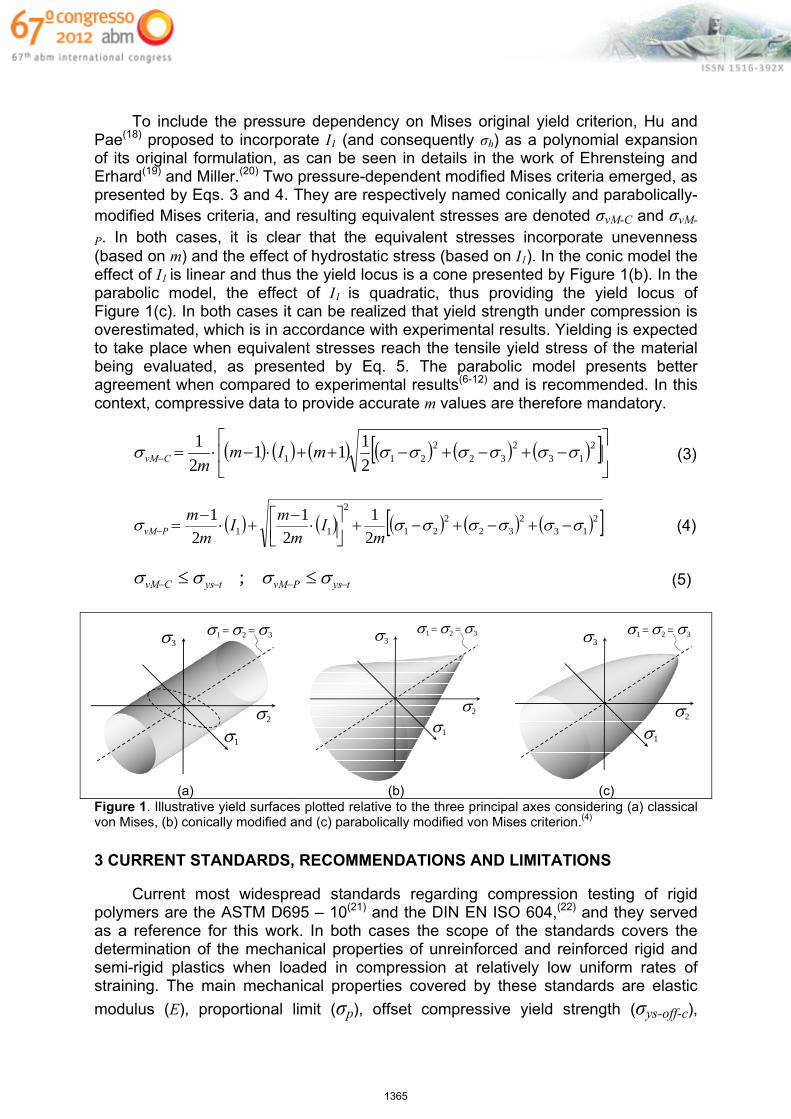
To include the pressure dependency on Mises original yield criterion, Hu and
Pae(18) proposed to incorporate I1 (and consequently σh) as a polynomial expansion of its original formulation, as can be seen in details in the work of Ehrensteing and Erhard(19) and Miller.(20) Two pressure-dependent modified Mises criteria emerged, as presented by Eqs. 3 and 4. They are respectively named conically and parabolically-modified Mises criteria, and resulting equivalent stresses are denoted σvM-C and σvM-
P. In both cases, it is clear that the equivalent stresses incorporate unevenness (based on m) and the effect of hydrostatic stress (based on I1). In the conic model the effect of I1 is linear and thus the yield locus is a cone presented by Figure 1(b). In the parabolic model, the effect of I1 is quadratic, thus providing the yield locus of Figure 1(c). In both cases it can be realized that yield strength under compression is overestimated, which is in accordance with experimental results. Yielding is expected to take place when equivalent stresses reach the tensile yield stress of the material being evaluated, as presented by Eq. 5. The parabolic model presents better agreement when compared to experimental results(6-12) and is recommended. In this context, compressive data to provide accurate m values are therefore mandatory.
213
232
2211 2
111
2
1 mImmCvM (3)
213
232
221
2
11 2
1
2
1
2
1
m
Im
mI
m
mPvM (4)
tysPvMtysCvM ; (5)
1
2
31 = 2 = 3
1
2
31 = 2 = 3
1
2
31 = 2 = 3
(a) (b) (c) Figure 1. Illustrative yield surfaces plotted relative to the three principal axes considering (a) classical von Mises, (b) conically modified and (c) parabolically modified von Mises criterion.(4)
3 CURRENT STANDARDS, RECOMMENDATIONS AND LIMITATIONS
Current most widespread standards regarding compression testing of rigid
polymers are the ASTM D695 – 10(21) and the DIN EN ISO 604,(22) and they served as a reference for this work. In both cases the scope of the standards covers the determination of the mechanical properties of unreinforced and reinforced rigid and semi-rigid plastics when loaded in compression at relatively low uniform rates of straining. The main mechanical properties covered by these standards are elastic
modulus (E), proportional limit (σp), offset compressive yield strength (σys-off-c),
1365

compressive yield strength (σys-max-c) and compressive ultimate strength (σucs). All definitions are based on engineering data and defined as (refer to Figure 2(a)): Elastic Modulus (E): slope of the stress-strain curve (between points B and C).
Proportional limit (σp): greatest stress that a material is capable of sustaining without deviation from Hooke’s Law (point C).
Offset compressive yield strength (σys-off-c): stress at which the stress-strain curve departs from linearity by a specified percent of deformation (point F).
Compressive yield strength (σys-max-c): stress at the point where an increase in strain occurs without an increase in stress (point H).
Compressive strength (σucs): maximum compressive stress carried by a test specimen during test (point J – in some cases, can be point H).
σ
ε
X
Non‐uniform plastic deformation.
Line parallel to the proportional regime with x % offset in ε.
Proportional regime.
A
C
F
D
B
H
J
p
coffys cys max
ucs
L
d
Compression tools: hardened steel and polished faces.
(a) (b) Figure 2. (a) Main mechanical properties evaluated for polymers under compression according to ASTM D695 – 10(21) and the DIN EN ISO 604.(22) (b) Compression specimen and loading scheme.
Both standards, at the very beginning, call the attention about the comparability of obtained properties. They indicate that tests carried out on specimens of different dimensions or with different preparation conditions (even if covered by the standard) may produce not comparable results. This work is not focused on simply following one standard or protocol to obtain comparable results. Conversely, the main objective here is to address setup parameters that lead to physically meaningful properties, which can guarantee similitude between stress-strain response of small-scale laboratory specimens and real structures, supporting design taking unevenness into account. In this context, the main recommendations of both standards are summarized in Table 1 and are detailed next to support further discussions.
Speed of testing is a very important parameter since polymers are highly sensitive to strain rate.(2-5) Higher strain rates provide higher mechanical properties. Speeds recommended by Table 1 try to ensure quasistatic loading (absence of dynamic phenomena), but at the same time cannot be so slow that relaxation and creep take a relevant amount. Depending on the applications, however, properties may be evaluated by using different speeds to address strain rate effects. In this work, speed of testing will follow the standards and quasistatic loading is desired.
Real-time displacement or strain can be measured using clip-gages or strain-gages attached directly to the specimen, optical sensors or the displacement of the actuators (in this case discounting machine compliance as recommended by Annex C of DIN EN ISO 604(22)). All of them are accurate according to the literature.
Specimen conditioning and recommended atmospheres for testing are also relevant since polymers can be hygroscopic and are highly sensitive to temperature.
1366
Higher temperatures decrease mechanical properties and favor time-dependent phenomena such as relaxation. Otherwise specified or relevant for specific applications, the standards should be adopted, as in this work.
The number of specimens, according to both standards supported by interlaboratory round-Robin tests, has proven to be statistically enough to guarantee comparable results. Results from Donato and Bianchi, in 2012(166) confirmed that 5 specimens provided very small scatter and therefore good repeatability.
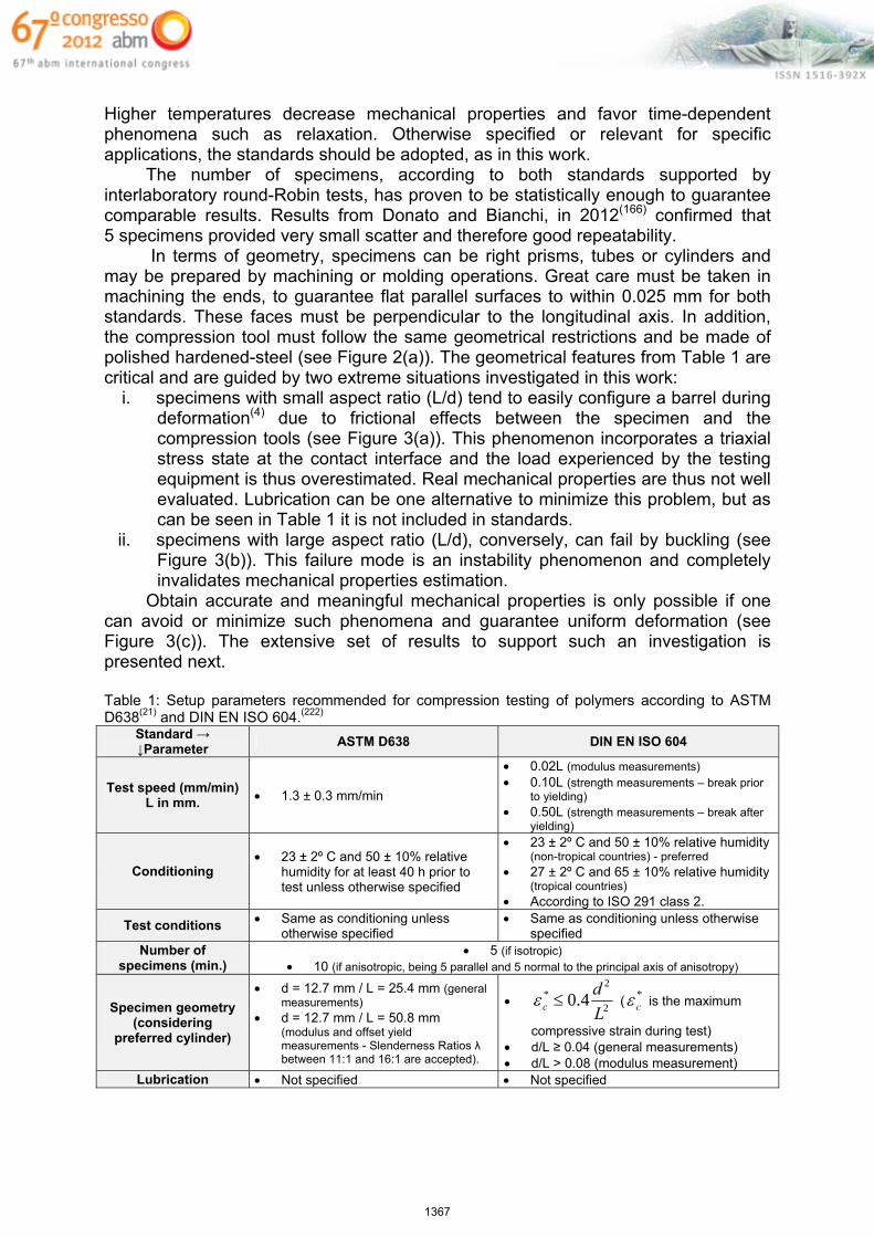
In terms of geometry, specimens can be right prisms, tubes or cylinders and may be prepared by machining or molding operations. Great care must be taken in machining the ends, to guarantee flat parallel surfaces to within 0.025 mm for both standards. These faces must be perpendicular to the longitudinal axis. In addition, the compression tool must follow the same geometrical restrictions and be made of polished hardened-steel (see Figure 2(a)). The geometrical features from Table 1 are critical and are guided by two extreme situations investigated in this work:
i. specimens with small aspect ratio (L/d) tend to easily configure a barrel during deformation(4) due to frictional effects between the specimen and the compression tools (see Figure 3(a)). This phenomenon incorporates a triaxial stress state at the contact interface and the load experienced by the testing equipment is thus overestimated. Real mechanical properties are thus not well evaluated. Lubrication can be one alternative to minimize this problem, but as can be seen in Table 1 it is not included in standards.
ii. specimens with large aspect ratio (L/d), conversely, can fail by buckling (see Figure 3(b)). This failure mode is an instability phenomenon and completely invalidates mechanical properties estimation.
Obtain accurate and meaningful mechanical properties is only possible if one can avoid or minimize such phenomena and guarantee uniform deformation (see Figure 3(c)). The extensive set of results to support such an investigation is presented next.
Table 1: Setup parameters recommended for compression testing of polymers according to ASTM D638(21) and DIN EN ISO 604.(222)
Standard → ↓Parameter
ASTM D638 DIN EN ISO 604
Test speed (mm/min) L in mm. 1.3 ± 0.3 mm/min
0.02L (modulus measurements) 0.10L (strength measurements – break prior
to yielding) 0.50L (strength measurements – break after
yielding)
Conditioning 23 ± 2º C and 50 ± 10% relative
humidity for at least 40 h prior to test unless otherwise specified
23 ± 2º C and 50 ± 10% relative humidity (non-tropical countries) - preferred
27 ± 2º C and 65 ± 10% relative humidity (tropical countries)
According to ISO 291 class 2.
Test conditions Same as conditioning unless otherwise specified
Same as conditioning unless otherwise specified
Number of specimens (min.)
5 (if isotropic) 10 (if anisotropic, being 5 parallel and 5 normal to the principal axis of anisotropy)
Specimen geometry (considering
preferred cylinder)
d = 12.7 mm / L = 25.4 mm (general measurements)
d = 12.7 mm / L = 50.8 mm (modulus and offset yield measurements - Slenderness Ratios λ between 11:1 and 16:1 are accepted).
2
2* 4.0
L
dc (
*c is the maximum
compressive strain during test) d/L ≥ 0.04 (general measurements) d/L > 0.08 (modulus measurement)
Lubrication Not specified Not specified
1367

(a) (b) (c)
Figure 3. Specimens made of POM illustrating the occurrence of (a) frictional effects leading to barreling (L/D = 1:1), (b) failure by buckling (L/D = 3,5:1) and (c) adequate situation were deformation proceeds in a uniform manner along specimen’s length (L/D = 2:1).
4 TESTED MATERIALS AND EXPERIMENTAL PROCEDURES
For completeness, three thermoplastic polymers of varying stiffness levels were tested under compression, including POM, Nylon 6 and HDPE. All materials were purchased from polymers distributors as round 3 meter long bars with 12.7 mm (½ inch) diameter. All specimens for each material were obtained from the same bar in order to avoid any shuffle or different batches. All of them were machined parallel and with its centers aligned to the longitudinal axis of the bars, in order to sample the same material characteristics. Machining was conducted in CNC machines with small passes to avoid residual stresses, bending or damage to the raw material. To be able to investigate the best setup parameters to provide physically meaningful mechanical properties (minimizing both friction and buckling), Table 2 presents specimens’ features for five different aspect ratios. All specimens presented 12.7 mm (½ inch) in diameter (d), but five different heights (L) were employed. As a consequence, L/d ratios from 1:1 until 4:1 could be tested covering suggestions from ASTM D695 standard(21) and slenderness ratios (λ) from DIN EN ISO 604.(22)
Table 2: Specimens’ dimensions investigated in this work
Parameter L/d = 1 L/d = 2 L/d = 3 L/d = 3.5 L/d = 4 L (mm) 12.7 25.4 38.1 44.5 50.8 d (mm) 12.7 12.7 12.7 12.7 12.7 L/d ( ) 1:1 2:1 3:1 3.5:1 4:1 λ ( ) 4.0 8.0 12.0 14.0 16.0
The specimens were kept and tested at 23 ºC and 60 % relative humidity, using the strain rate recommended by ASTM D695(21) for compression (0.051 min-1). Five valid specimens were tested for each material and considered condition. A 30 kN electromechanical INSTRON testing machine (model 5567) was employed with polished compression tools. All tests were conducted without lubrication and then replicated including lubricant (DOW Corning Molykote A-2 grease).
5 EXPERIMENTAL RESULTS AND DISCUSSION
Very good agreement was verified between stress-strain curves from all five specimens for each material and condition. Curves are not reported here, but all of them increased continuously in terms of stress levels without a maximum point as defined in Figure 2(a). Some of the specimens failed by buckling, while others did not
1368

fail and the test was interrupted for ε = 50%. Elastic moduli and offset compressive yield strength could be post-processed for all specimens. Figure 4(a,c,e) presents the effect of specimen length (and thus aspect ratio) and lubrication on elastic moduli (E). The absence of lubrication clearly causes an overestimation of E for all materials, mainly for aspect ratios between L/d = 2 and L/d = 3 for Nylon 6 and HDPE (low stiffness). In the case of POM the effectiveness of the employed lubricant was reduced due to its high stiffness, but the same trend was slightly observed. In general, lengths larger than 38.1 mm (which means L/d = 3) are not recommended since buckling phenomena frequently took place and deviations increased, even for POM. Figure 4(b,d,f) presents the effects of lubrication on compressive yield strength for L/d = 2 and L/d = 3 and varying offsets. Once again, lubrication clearly minimize friction effects avoiding stress overestimation (result of barreling). In addition, L/d = 3 (L = 38.1 mm) revealed the lower-bound yield strength for all cases.
0.5
0.6
0.7
0.8
0.9
1.0
1.1
1.2
1.3
1.4
1.5
0 12.7 25.4 38.1 50.8 63.5
E(M
Pa)
Specimen length (mm)
Nylon 6
With lubricant. No lubricant - dry.
15
20
25
30
35
40
0.00% 0.50% 1.00% 1.50% 2.00% 2.50%
σys
-0ff-
c(M
Pa)
Offset for yield definition (%)
Nylon 6
d = 25.4 mm - lubricant. d = 25.4 mm - dry.
d = 38.1 mm - lubricant. d = 38.1 mm - dry.
(a) (b)
0.5
0.6
0.7
0.8
0.9
1.0
1.1
1.2
1.3
1.4
1.5
0 12.7 25.4 38.1 50.8 63.5
E(M
Pa
)
Specimen length (mm)
HDPE
With lubricant. No lubricant - dry.
5
10
15
20
25
0.00% 0.50% 1.00% 1.50% 2.00% 2.50%
σys
-0ff-
c(M
Pa)
Offset for yield definition (%)
HDPE
d = 25.4 mm - lubricant. d = 25.4 mm - dry.
d = 38.1 mm - lubricant. d = 38.1 mm - dry.
(c) (d)
1.5
1.8
2.0
2.3
2.5
2.8
3.0
0 12.7 25.4 38.1 50.8 63.5
E(M
Pa
)
Specimen length (mm)
POM
With lubricant. No lubricant - dry.
20
30
40
50
60
70
80
90
100
0.00% 0.50% 1.00% 1.50% 2.00% 2.50%
σys
-0ff-
c(M
Pa)
Offset for yield definition (%)
POM
d = 25.4 mm - lubricant. d = 25.4 mm - dry.
d = 38.1 mm - lubricant. d = 38.1 mm - dry.
(e) (f)
Figure 4. Selected stress-strain curves to show the effects of (a) lubrication and (b) specimen length on the three tested materials.
To corroborate the insights that emerged from Figure 4, Figure 5 presents the effects of lubrication and offset level on compressive yield strength for all specimen lengths. Clearly the use of lubrication minimizes yield strength estimation (compare
1369

Figures 5(a,c,e) to Figures 5(b,d,f)), which is physically meaningful and desired. On the other hand, if aspect ratios larger than L/d = 3 are employed, buckling takes place and deviations increase. The evaluated offset levels, as expected, presented a direct relationship to the evaluated yield strength, and the user is encouraged to match its real application (in terms of operating strain level and required safety) to the adequate offset definition. Attention to relaxation phenomena and permanent loading is required. The use of round specimens with aspect ratios around L/d = 3 and lubrication on compression tools emerge as an interesting approach to minimize scatter, friction and at the same time, avoid buckling in the cases under investigation.
15
20
25
30
35
40
0 12.7 25.4 38.1 50.8 63.5
σys
-0ff-
c(M
Pa)
Specimen length (mm)
Nylon 6 - with lubricant
0.2% - lubricant. 0.5% - lubricant.
1.0% - lubricant. 2.0% - lubricant.
15
20
25
30
35
40
0 12.7 25.4 38.1 50.8 63.5
σys
-0ff-
c(M
Pa)
Specimen length (mm)
Nylon 6 - no lubricant
0.2% - dry. 0.5% - dry.
1.0% - dry. 2.0% - dry.
(a) (b)
5
10
15
20
25
0 12.7 25.4 38.1 50.8 63.5
σys
-0ff-
c(M
Pa)
Specimen length (mm)
HDPE - with lubricant
0.2% - lubricant. 0.5% - lubricant.
1.0% - lubricant. 2.0% - lubricant.
5
10
15
20
25
0 12.7 25.4 38.1 50.8 63.5
σys
-0ff-
c(M
Pa)
Specimen length (mm)
HDPE - no lubricant
0.2% - dry. 0.5% - dry.
1.0% - dry. 2.0% - dry.
(c) (d)
20
30
40
50
60
70
80
90
100
0 12.7 25.4 38.1 50.8 63.5
σys
-0ff-
c(M
Pa)
Specimen length (mm)
POM- with lubricant
0.2% - lubricant. 0.5% - lubricant.
1.0% - lubricant. 2.0% - lubricant.
20
30
40
50
60
70
80
90
100
0 12.7 25.4 38.1 50.8 63.5
σys
-0ff-
c(M
Pa)
Specimen length (mm)
POM- no lubricant
0.2% - dry. 0.5% - dry.
1.0% - dry. 2.0% - dry.
(e) (f)
Figure 5. Yield strength under compression considering different specimen length and offset yield definitions for (a) Nylon 6 with lubricant, (b) Nylon 6 without lubricant, (c) HDPE with lubricant, (d) HDPE without lubricant, (e) POM with lubricant and (f) POM without lubricant. 6 CONCLUDING REMARKS
From this work it is possible to conclude that: The absence of lubrication clearly causes an overestimation of E and σys-off-
c for all materials. Lubrication is thus recommended to provide physically
1370

meaningful data minimizing friction and stress triaxiality. Testing of polymers with high stiffness may employ high performance solid lubricants.
In general, aspect ratios larger than L/d = 3 (which means lengths larger than 38.1 mm in this case) are not recommended since buckling phenomena frequently took place and deviations increased.
The same aspect ratio (L/d = 3) revealed, combined to adequate lubrication, the lower-bound yield strength and coherent elastic modulus for all cases.
The use of round specimens with aspect ratios around L/d = 3 and lubrication on compression tools emerge thus as an interesting approach to provide meaningful properties, minimizing scatter, friction and buckling.
Acknowledgment
This work is supported by Centro Universitário da FEI, São Paulo, Brazil.
REFERENCES
1 CRAWFORD, R. J. Plastic Engineering, 3rd ed., Butterworth Heinemann, Oxford, 2002. 2 SHAH, V. Handbook of Plastic Testing Technology, 2nd ed., Wiley, California, USA,
1998. 3 NIELSEN, E. L.; LANDEL, L. F. Mechanical Properties of Polymers and Composites.
2nd ed., Marcel Dekker, New York, USA 1994. 4 ROESLER, J.; HARDERS, H.; BAEKER, M. Mechanical Behavior of Engineering
Materials. Metals, Ceramics, Polymers and Composites. 1st edition, Springer, USA, 2007.
5 BOWER, D. I. An Introduction to Polymer Physics, Cambridge Press, USA, 2002. 6 WARD, I. M.; SWEENEY, J. An Introduction to the Mechanical Properties of Solid
Polymers, New York, USA, 1972. 7 LYON, R. E. Physical Basis for a Pressure-Dependent Yield Criterion for Polymers,
U.S. Army Laboratory Command, Ballistic Research Laboratory, USA, 1992. 8 PAE, K. D.; BHATEJA, S. K. The Effects of Hydrostatic Pressure on the Mechanical
Behavior of Polymers. Journal of Macromolecular Science, Part C: Polymer Reviews, v. 13, p. 1 – 75, 1975.
9 ASTM Standard D638 - 08. Standard Test Method for Tensile Properties of Plastics, USA, 2008.
10 DIN EN ISO 527-1. General principles for the determination of tensile properties, Berlin, 1996.
11 RAGHAVA, R.; CADDELL, R. M. The Macroscopic Yield Behavior of Polymers, 1973. 12 CADDELL, R. M.; RAGHAVA, R. S.; ATKINS, A. G. Pressure Dependent Yield Criteria
for Polymers, Materials Science and Engineering, V. 13, Issue 2, p. 113-120, 1974. 13 MASCARENHAS, W. N.; AHRENS, C. H.; OGLIARI, A. Design criteria and safety
factors for plastic components design, Materials and Design, V. 25, p. 257–261, 2004. 14 JERABEK, M.; STEINBERGER, R.; MAJOR, Z. Characterization of the compression
behaviour of engineering polymers, 22nd DANUBIA-ADRIA Symposium, Parma, Italy, 2005.
15 CES EDUPACK 2009 – Software for Materials Selection. Granta Design, 2009. 16 DONATO, G. H. B.; BIANCHI, M. Pressure dependent yield criteria applied for
improving design practices and integrity assessments against yielding of engineering polymers, Journal of Materials Research and Technology (accepted for publication – in press), 2012.
17 VON MISES, R. Mechanik der festen Körper im plastisch deformablen Zustand. Göttin. Nachr. Math. Phys., vol. 1, pp. 582–592, Germany, 1913.
18 HU, L. W.; PAE, K. D. Inclusion of the Hydrostatic Stress Component in Formulation of the Yield Condition, Journal of Franklin Institute, V. 275, Issue 6, Pages 491-502, 1963.
1371

19 EHRENSTEIN G. W.; ERHARD G. Designing with Plastic: a Report on the State of the Art, Carl Hanser Verlag, Munich, Germany, 1994.
20 MILLER, E. Introduction to Plastic and Composites: Mechanical Properties and Engineering Applications, Marcel Dekker Inc., New York, USA, 1996.
21 ASTM Standard D695 - 10. Standard Test Method for Compressive Properties of Rigid Plastics, ASTM International, Pennsylvania, USA, 2010.
22 DIN EN ISO 604. Determination of compressive properties, Deutsches Institut für Normung, Germany, 2003.
1372


![Recommended Practices for Selection and Use of Packaging ... Recommended... · Recommended Practices for Selection and Use of Packaging Systems for Sterilization [Clinical] Originally](https://static.fdocuments.in/doc/165x107/5fc006e41a10927217221452/recommended-practices-for-selection-and-use-of-packaging-recommended-recommended.jpg)