RECENT INNOVATIONS IN SIMIO - Semantic Scholar€¦ · · 2017-05-03RECENT INNOVATIONS IN SIMIO...
11
Proceedings of the 2014 Winter Simulation Conference A. Tolk, S. Y. Diallo, I. O. Ryzhov, L. Yilmaz, S. Buckley, and J. A. Miller, eds. RECENT INNOVATIONS IN SIMIO Renee M. Thiesing C. Dennis Pegden Simio LLC 504 Beaver St. Sewickley, PA, 15143, USA ABSTRACT This paper briefly describes Simio TM simulation software, a simulation modeling framework based on in- telligent objects. It then describes a few of the many recent enhancements and innovations including SMORE charts that allow unprecedented insight into your simulation output, sophisticated built-in exper- imentation that incorporates multi-processor support, optimization, along with new features for input analysis, Risk-based Planning and Scheduling (RPS), and Dashboards for sharing simulation results throughout the enterprise. 1 SIMIO BASIC CONCEPTS The Simio modeling software lets you build and run dynamic 3D animated models of a wide range of sys- tems – e.g., factories, supply chains, emergency departments, airports, and service systems. Simio em- ploys an object approach to modeling, whereby models are built by combining objects that represent the physical components of the systems. An object has its own custom behavior as defined by its internal model that responds to events in the system. For example, a production line model is built by placing objects that represent machines, con- veyors, forklift trucks, aisles, etc. You can build your models using the objects provided in the Standard Object Library, which is a general purpose set of objects that comes standard with Simio. You can also build your own libraries of objects that are customized for specific application areas. As you will see shortly, you can also modify and extend the Standard Library object behavior using process logic. One of the powerful features of Simio is that whenever you build a model of a system, you can turn that model into an object definition by simply adding some input properties and an external view. Your model can then be placed as a sub-model within a higher-level model. Hence, hierarchical modeling is very natural in Simio. 2 SIMIO OBJECTS Simio is a simulation modeling framework based on intelligent objects. The intelligent objects are built by modelers and then may be reused in multiple modeling projects. Objects can be stored in libraries and easily shared. A beginning modeler may prefer to use pre-built objects from libraries, however the system is designed to make it easy for even beginning modelers to build their own intelligent objects for use in building hierarchical models. An object might be a machine, robot, airplane, customer, doctor, tank, bus, ship, or any other thing that you might encounter in your system. A model is built by combining objects that represent the physi- cal components of the system. The model logic and animation is built as a single step. 4228 978-1-4799-7486-3/14/$31.00 ©2014 IEEE
Transcript of RECENT INNOVATIONS IN SIMIO - Semantic Scholar€¦ · · 2017-05-03RECENT INNOVATIONS IN SIMIO...
Proceedings of the 2014 Winter Simulation Conference
A. Tolk, S. Y. Diallo, I. O. Ryzhov, L. Yilmaz, S. Buckley, and J. A. Miller, eds.
RECENT INNOVATIONS IN SIMIO
Renee M. Thiesing
C. Dennis Pegden
Simio LLC
504 Beaver St.
Sewickley, PA, 15143, USA
ABSTRACT
This paper briefly describes SimioTM
simulation software, a simulation modeling framework based on in-
telligent objects. It then describes a few of the many recent enhancements and innovations including
SMORE charts that allow unprecedented insight into your simulation output, sophisticated built-in exper-
imentation that incorporates multi-processor support, optimization, along with new features for input
analysis, Risk-based Planning and Scheduling (RPS), and Dashboards for sharing simulation results
throughout the enterprise.
1 SIMIO BASIC CONCEPTS
The Simio modeling software lets you build and run dynamic 3D animated models of a wide range of sys-
tems – e.g., factories, supply chains, emergency departments, airports, and service systems. Simio em-
ploys an object approach to modeling, whereby models are built by combining objects that represent the
physical components of the systems.
An object has its own custom behavior as defined by its internal model that responds to events in the
system. For example, a production line model is built by placing objects that represent machines, con-
veyors, forklift trucks, aisles, etc. You can build your models using the objects provided in the Standard
Object Library, which is a general purpose set of objects that comes standard with Simio. You can also
build your own libraries of objects that are customized for specific application areas. As you will see
shortly, you can also modify and extend the Standard Library object behavior using process logic.
One of the powerful features of Simio is that whenever you build a model of a system, you can turn
that model into an object definition by simply adding some input properties and an external view. Your
model can then be placed as a sub-model within a higher-level model. Hence, hierarchical modeling is
very natural in Simio.
2 SIMIO OBJECTS
Simio is a simulation modeling framework based on intelligent objects. The intelligent objects are built
by modelers and then may be reused in multiple modeling projects. Objects can be stored in libraries and
easily shared. A beginning modeler may prefer to use pre-built objects from libraries, however the system
is designed to make it easy for even beginning modelers to build their own intelligent objects for use in
building hierarchical models.
An object might be a machine, robot, airplane, customer, doctor, tank, bus, ship, or any other thing
that you might encounter in your system. A model is built by combining objects that represent the physi-
cal components of the system. The model logic and animation is built as a single step.
4228978-1-4799-7486-3/14/$31.00 ©2014 IEEE
Thiesing and Pegden
Objects are built using the concepts of object-orientation. However unlike other object-oriented sim-
ulation systems, the process of building an object is very simple and completely graphical. There is no
need to write programming code to create new objects.
The activity of building an object in Simio is identical to the activity of building a model. Whenever
you build a model it is by definition an object that can be instantiated into another model. For example, if
you combine two machines and a robot into a model of a work cell, the work cell model is itself an object
that can then be instantiated any number of times into other models.
3 SIMIO USER INTERFACE
When you first open Simio you are looking at the Facility window of a new model. Models are defined
within a project. A project may contain any number of models and associated experiments (discussed lat-
er). A project will typically contain a main model and an entity model. The entity model is used to de-
fine the behavior of the entities that move through the system. The default model entity is “dumb” in that
it has no explicit behavior, however as you will see later, you can modify the entity model to take specific
actions in response to events. You can also have multiple types of entity models in your project, with
each having its own behavior. For example in a model of an emergency department you could have dif-
ferent entities representing patients, nurses, and doctors.
A project can also be loaded into Simio as modeling library. Hence, some projects contain a collec-
tion of models for a specific application, and other projects contain models that are primarily used as
building blocks for other models. The same project can either be opened for editing or be loaded as li-
brary.
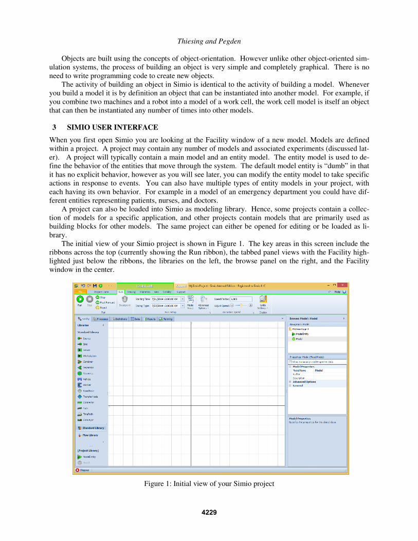
The initial view of your Simio project is shown in Figure 1. The key areas in this screen include the
ribbons across the top (currently showing the Run ribbon), the tabbed panel views with the Facility high-
lighted just below the ribbons, the libraries on the left, the browse panel on the right, and the Facility
window in the center.
Figure 1: Initial view of your Simio project
4229
Thiesing and Pegden
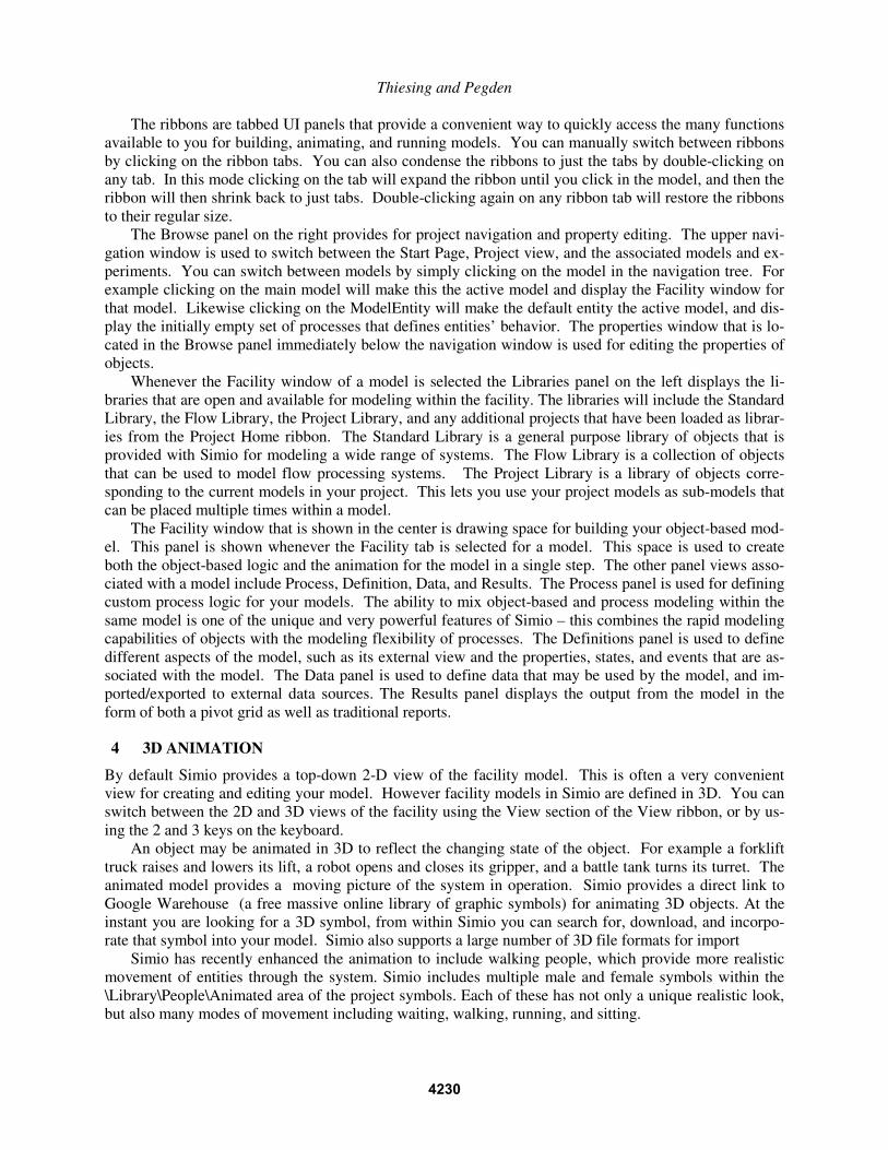
The ribbons are tabbed UI panels that provide a convenient way to quickly access the many functions
available to you for building, animating, and running models. You can manually switch between ribbons
by clicking on the ribbon tabs. You can also condense the ribbons to just the tabs by double-clicking on
any tab. In this mode clicking on the tab will expand the ribbon until you click in the model, and then the
ribbon will then shrink back to just tabs. Double-clicking again on any ribbon tab will restore the ribbons
to their regular size.
The Browse panel on the right provides for project navigation and property editing. The upper navi-
gation window is used to switch between the Start Page, Project view, and the associated models and ex-
periments. You can switch between models by simply clicking on the model in the navigation tree. For
example clicking on the main model will make this the active model and display the Facility window for
that model. Likewise clicking on the ModelEntity will make the default entity the active model, and dis-
play the initially empty set of processes that defines entities’ behavior. The properties window that is lo-
cated in the Browse panel immediately below the navigation window is used for editing the properties of
objects.
Whenever the Facility window of a model is selected the Libraries panel on the left displays the li-
braries that are open and available for modeling within the facility. The libraries will include the Standard
Library, the Flow Library, the Project Library, and any additional projects that have been loaded as librar-
ies from the Project Home ribbon. The Standard Library is a general purpose library of objects that is
provided with Simio for modeling a wide range of systems. The Flow Library is a collection of objects
that can be used to model flow processing systems. The Project Library is a library of objects corre-
sponding to the current models in your project. This lets you use your project models as sub-models that
can be placed multiple times within a model.
The Facility window that is shown in the center is drawing space for building your object-based mod-
el. This panel is shown whenever the Facility tab is selected for a model. This space is used to create
both the object-based logic and the animation for the model in a single step. The other panel views asso-
ciated with a model include Process, Definition, Data, and Results. The Process panel is used for defining
custom process logic for your models. The ability to mix object-based and process modeling within the
same model is one of the unique and very powerful features of Simio – this combines the rapid modeling
capabilities of objects with the modeling flexibility of processes. The Definitions panel is used to define
different aspects of the model, such as its external view and the properties, states, and events that are as-
sociated with the model. The Data panel is used to define data that may be used by the model, and im-
ported/exported to external data sources. The Results panel displays the output from the model in the
form of both a pivot grid as well as traditional reports.
4 3D ANIMATION
By default Simio provides a top-down 2-D view of the facility model. This is often a very convenient
view for creating and editing your model. However facility models in Simio are defined in 3D. You can
switch between the 2D and 3D views of the facility using the View section of the View ribbon, or by us-
ing the 2 and 3 keys on the keyboard.
An object may be animated in 3D to reflect the changing state of the object. For example a forklift
truck raises and lowers its lift, a robot opens and closes its gripper, and a battle tank turns its turret. The
animated model provides a moving picture of the system in operation. Simio provides a direct link to
Google Warehouse (a free massive online library of graphic symbols) for animating 3D objects. At the
instant you are looking for a 3D symbol, from within Simio you can search for, download, and incorpo-
rate that symbol into your model. Simio also supports a large number of 3D file formats for import
Simio has recently enhanced the animation to include walking people, which provide more realistic
movement of entities through the system. Simio includes multiple male and female symbols within the
\Library\People\Animated area of the project symbols. Each of these has not only a unique realistic look,
but also many modes of movement including waiting, walking, running, and sitting.
4230
Thiesing and Pegden
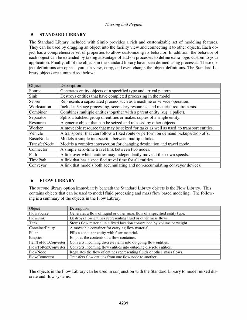
5 STANDARD LIBRARY
The Standard Library included with Simio provides a rich and customizable set of modeling features.
They can be used by dragging an object into the facility view and connecting it to other objects. Each ob-
ject has a comprehensive set of properties to allow customizing its behavior. In addition, the behavior of
each object can be extended by taking advantage of add-on processes to define extra logic custom to your
application. Finally, all of the objects in the standard library have been defined using processes. These ob-
ject definitions are open – you can view, copy, and even change the object definitions. The Standard Li-
brary objects are summarized below:
6 FLOW LIBRARY
The second library option immediately beneath the Standard Library objects is the Flow Library. This
contains objects that can be used to model fluid processing and mass flow based modeling. The follow-
ing is a summary of the objects in the Flow Library.
Object Description
FlowSource Generates a flow of liquid or other mass flow of a specified entity type.
FlowSink Destroys flow entities representing fluid or other mass flows.
Tank Stores flow material in a fixed location constrained by volume or weight.
ContainerEntity A moveable container for carrying flow material.
Filler Fills a container entity with flow material.
Emptier Empties the contents of a flow container.
ItemToFlowConverter Converts incoming discrete items into outgoing flow entities.
FlowToItemConverter Converts incoming flow entities into outgoing discrete entities.
FlowNode Regulates the flow of entities representing fluids or other mass flows.
FlowConnector Transfers flow entities from one flow node to another.
The objects in the Flow Library can be used in conjunction with the Standard Library to model mixed dis-
crete and flow systems.
Object Description
Source Generates entity objects of a specified type and arrival pattern.
Sink Destroys entities that have completed processing in the model.
Server Represents a capacitated process such as a machine or service operation.
Workstation Includes 3 stage processing, secondary resources, and material requirements.
Combiner Combines multiple entities together with a parent entity (e.g. a pallet).
Separator Splits a batched group of entities or makes copies of a single entity.
Resource A generic object that can be seized and released by other objects.
Worker A moveable resource that may be seized for tasks as well as used to transport entities.
Vehicle A transporter that can follow a fixed route or perform on demand pickups/drop offs.
BasicNode Models a simple intersection between multiple links.
TransferNode Models a complex intersection for changing destination and travel mode.
Connector A simple zero-time travel link between two nodes.
Path A link over which entities may independently move at their own speeds.
TimePath A link that has a specified travel time for all entities.
Conveyor A link that models both accumulating and non-accumulating conveyor devices.
4231
Thiesing and Pegden
7 CRANE LIBRARY
The Simio Crane Library is a collection of objects designed for modeling multiple cranes operating simul-
taneously in a bay. The library is provided as an example of complex material handling using the standard
features of Simio. The Crane library may be used in conjunction with the Simio Standard Library or with
custom libraries that support rider pickups using the standard transporter ride features.
The Crane Library consists of objects representing the Bay, Bridge, Cab, Lift, and Crane. These ob-
jects are combined together to model multiple cranes moving in a single bay. The Crane library fully sup-
ports independent acceleration/deceleration and the ability for one crane to cause another blocking crane
to move out of the way. It also supports the new style of underhung cranes that permit movement of cabs
from bridge to bridge, and even between adjacent bays.
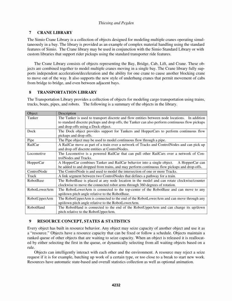
8 TRANSPORTATION LIBRARY
The Transportation Library provides a collection of objects for modeling cargo transportation using trains,
trucks, boats, pipes, and robots. The following is a summary of the objects in the library.
Object Description
Tanker The Tanker is used to transport discrete and flow entities between node locations. In addition
to standard discrete pickups and drop offs, the Tanker can also perform continuous flow pickups
and drop-offs using a Dock object.
Dock The Dock object provides support for Tankers and HopperCars to perform continuous flow
pickups and drop offs.
Pipe The Pipe object may be used to model continuous flow through a pipe.
RailCar A RailCar move as part of a train over a network of Tracks and ControlNodes and can pick up
and drop off discrete entities at ControlNodes.
Locomotive The Locomotive is a powered RailCar that can pull other RailCars over a network of Con-
trolNodes and Tracks.
HopperCar A HopperCar combines Tanker and RailCar behavior into a single object. A HopperCar can
be added to and dropped from trains, and may perform continuous flow pickups and drop-offs.
ControlNode The ControlNode is and used to model the intersection of one or more Tracks.
Track A link segment between two ControlNodes that defines a pathway for a train.
RobotBase The RobotBase is placed at any node location in the model and can rotate clockwise/counter
clockwise to move the connected robot arms through 360 degrees of rotation.
RobotLowerArm The RobotLowerArm is connected to the top-center of the RobotBase and can move to any
up/down pitch angle relative to the RobotBase.
RobotUpperArm The RobotUpperArm is connected to the end of the RobotLowerArm and can move through any
up/down pitch angle relative to the RobotLowerArm.
RobotHand The RobotHand is connected to the end of the RobotUpperArm and can change its up/down
pitch relative to the RobotUpperArm.
9 RESOURCE CONCEPT, STATES & STATISTICS
Every object has built in resource behavior. Any object may seize capacity of another object and use it as
a “resource.” Objects have a resource capacity that can be fixed or follow a schedule. Objects maintain a
ranked queue of other objects that are waiting to seize capacity. When an object is released it is reallocat-
ed by either selecting the first in the queue, or dynamically selecting from all waiting objects based on a
rule.
Objects can intelligently interact with each other and the environment. A resource may reject a seize
request if it is for example, batching up work of a certain type, or too close to a break to start new work.
Resources have automatic state-based and overall statistics collection as well as optional animation.
4232
Thiesing and Pegden
10 PROCESSES
Object-based tools such Simio are very good for rapidly building models. You simply drag objects into
the workspace, set the properties for those objects, and your model is ready to run. However the tradi-
tional problem with this approach is modeling flexibility. It’s extremely difficult to design a set of ob-
jects that work in all situations across multiple and disparate application areas without making the objects
overly complicated and difficult to learn and use.
The Simio Standard Library addresses this problem through the concept of add-on processes. An
add-on process is a small piece of logic that can be inserted into the Standard Library objects at selected
points to perform some custom logic. This custom logic can be used to seize/release resources, make as-
signments to variables, change travel networks, evaluate alternatives, etc. The processes are created as
graphical flowcharts without the need for programming. Hence Simio combines the benefits of object-
based modeling with the power and flexibility of graphical process modeling.
Process logic can be inserted into an object on an instance by instance basis, without modifying or
changing the main object definition. For example one Server instance might incorporate process logic to
seize and move a secondary resource during processing, while another instance for the same Server defi-
nition incorporates special logic to calculate the processing time based on a learning curve, and a third in-
stance of the same Server incorporates special process logic for modeling a complex repair process. All
these instances share the same Server definition but customize each instance as needed.
Another thing that is particularly powerful about add-on processes is that – unlike a programming in-
sert - processes can span simulated time. For example a process can wait for tank to fill, a resource to be-
come idle, or a queue to reduce to a specific size. Hence processes are not only easier to learn, create, and
understand, they are also significantly more powerful than programming inserts.
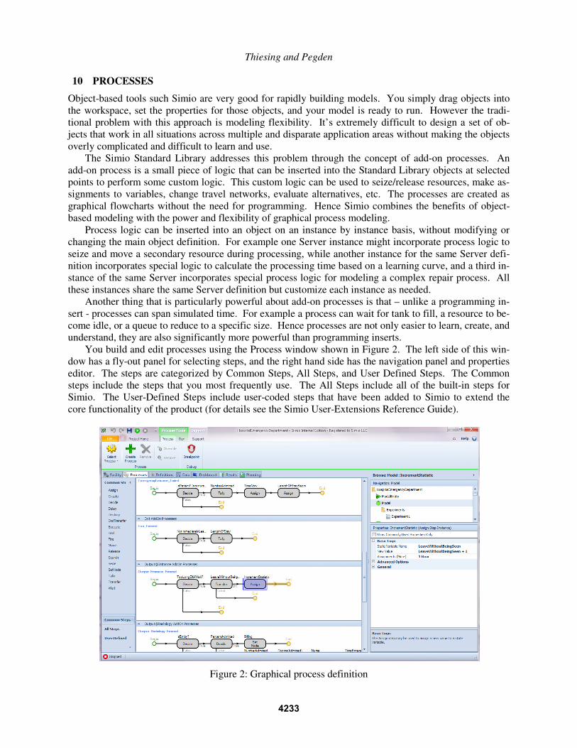
You build and edit processes using the Process window shown in Figure 2. The left side of this win-
dow has a fly-out panel for selecting steps, and the right hand side has the navigation panel and properties
editor. The steps are categorized by Common Steps, All Steps, and User Defined Steps. The Common
steps include the steps that you most frequently use. The All Steps include all of the built-in steps for
Simio. The User-Defined Steps include user-coded steps that have been added to Simio to extend the
core functionality of the product (for details see the Simio User-Extensions Reference Guide).
Figure 2: Graphical process definition
4233
Thiesing and Pegden
11 BUILDING OBJECTS
One way to build a new object definition is simply by combining other objects. Essentially as you are
building a model, you are also building an object. This type of object is called a composed object because
we create this object by combining two or more component objects. This object building approach is ful-
ly hierarchical, i.e., a composed object can be used as a component object in building higher level objects.
And you can now select which components are visible and animated when others use your object. You
would typically add a custom user view and properties in order to make this type of object customizable
by others. This is only one way of building objects in Simio - there are two other important methods.
The most basic method for creating objects in Simio is by defining the logical processes that alter
their state in response to events. For example, a machine object might be built by defining the processes
that alter the machine state as events occur such as part arrival, tool breakdown, etc. This type of model-
ing is similar to the process modeling done in traditional modeling systems in use today such as Arena or
GPSS. An object that is defined by describing its native processes is called a base object. A base object
can in turn be used as a component object for building higher level objects.
The final method for building objects in Simio is based on the concept of inheritance. In this case we
create an object from an existing object by overriding (i.e., replacing) one or more processes within the
object, or adding additional processes to extend its behavior. In other words we start with an object that is
almost what we want, and then we modify and extend it as necessary to make it serve our own purpose.
For example we might build a specialized drill object from a generalized machine object by adding addi-
tional processes to handle the failure and replacement of the drill bit. An object that is built in this way is
referred to as a derived object because it is sub-classed from an existing object.
Regardless of which method is used to create an object, once created it is used in exactly the same
way. An object can be instantiated any number of times into a model. You simply select the object of in-
terest and place it (instantiate it) into your model.
12 EXPERIMENT WINDOW
There are two basic modes for executing models in Simio. The first mode is interactive mode where you
can watch the animated model execute and view dynamic charts and plots that summarize the system be-
havior. This is useful for building and verifying/validating the model as well as getting general insight
into how the system will perform. Once the model has been validated the next step is typically to define
specific scenarios to test with the model. In this case we have no interest in the animation and we would
like to replicate each scenario to account for the underlying variability in the system and to reach statisti-
cally valid conclusions from the model.
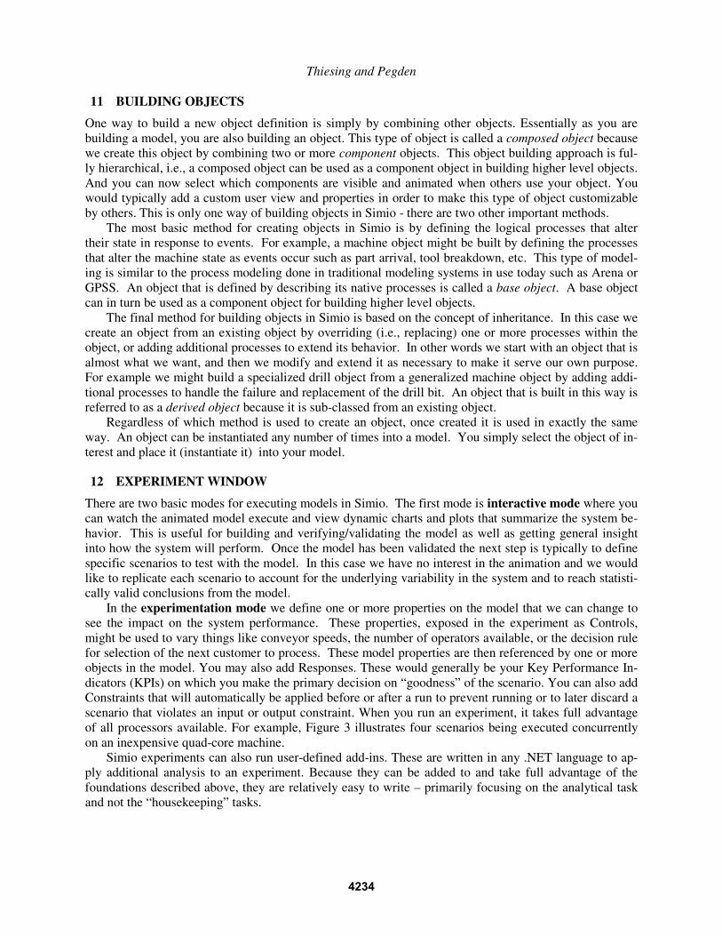
In the experimentation mode we define one or more properties on the model that we can change to
see the impact on the system performance. These properties, exposed in the experiment as Controls,
might be used to vary things like conveyor speeds, the number of operators available, or the decision rule
for selection of the next customer to process. These model properties are then referenced by one or more
objects in the model. You may also add Responses. These would generally be your Key Performance In-
dicators (KPIs) on which you make the primary decision on “goodness” of the scenario. You can also add
Constraints that will automatically be applied before or after a run to prevent running or to later discard a
scenario that violates an input or output constraint. When you run an experiment, it takes full advantage
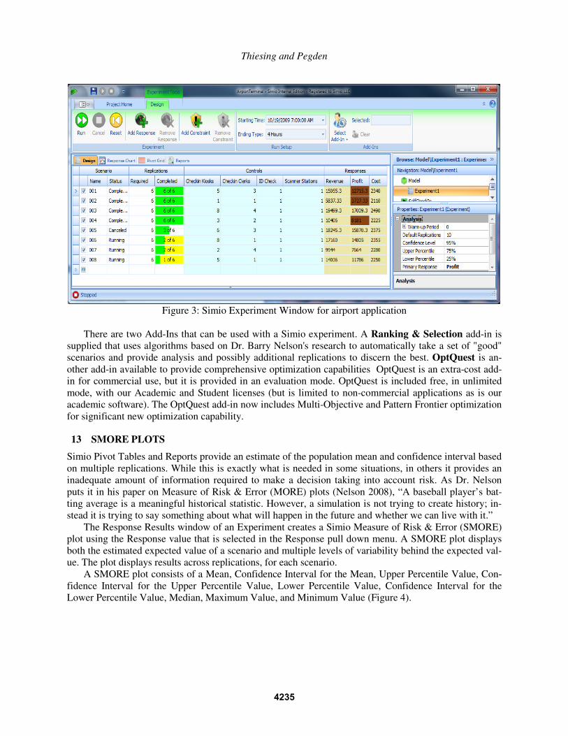
of all processors available. For example, Figure 3 illustrates four scenarios being executed concurrently
on an inexpensive quad-core machine.
Simio experiments can also run user-defined add-ins. These are written in any .NET language to ap-
ply additional analysis to an experiment. Because they can be added to and take full advantage of the
foundations described above, they are relatively easy to write – primarily focusing on the analytical task
and not the “housekeeping” tasks.
4234
Thiesing and Pegden
Figure 3: Simio Experiment Window for airport application
There are two Add-Ins that can be used with a Simio experiment. A Ranking & Selection add-in is
supplied that uses algorithms based on Dr. Barry Nelson's research to automatically take a set of "good"
scenarios and provide analysis and possibly additional replications to discern the best. OptQuest is an-
other add-in available to provide comprehensive optimization capabilities OptQuest is an extra-cost add-
in for commercial use, but it is provided in an evaluation mode. OptQuest is included free, in unlimited
mode, with our Academic and Student licenses (but is limited to non-commercial applications as is our
academic software). The OptQuest add-in now includes Multi-Objective and Pattern Frontier optimization
for significant new optimization capability.
13 SMORE PLOTS
Simio Pivot Tables and Reports provide an estimate of the population mean and confidence interval based
on multiple replications. While this is exactly what is needed in some situations, in others it provides an
inadequate amount of information required to make a decision taking into account risk. As Dr. Nelson
puts it in his paper on Measure of Risk & Error (MORE) plots (Nelson 2008), “A baseball player’s bat-
ting average is a meaningful historical statistic. However, a simulation is not trying to create history; in-
stead it is trying to say something about what will happen in the future and whether we can live with it.”
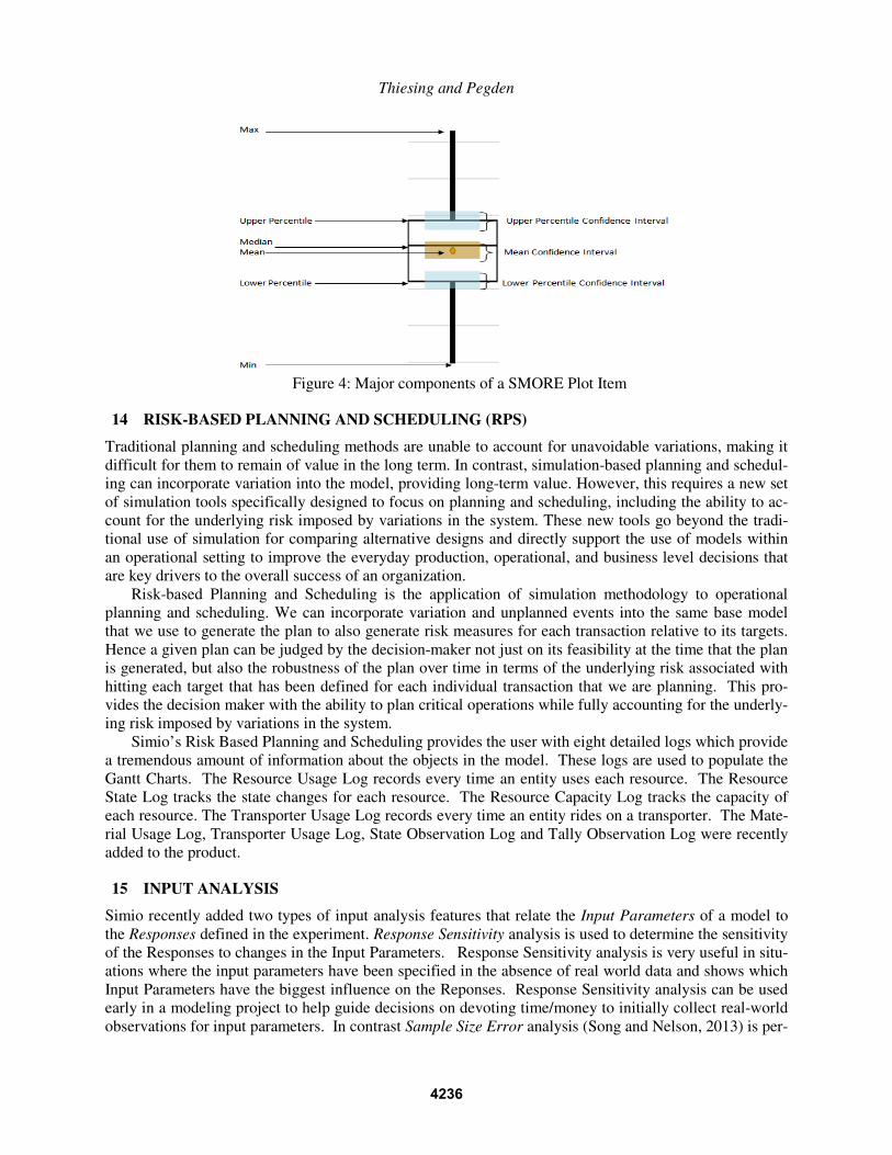
The Response Results window of an Experiment creates a Simio Measure of Risk & Error (SMORE)
plot using the Response value that is selected in the Response pull down menu. A SMORE plot displays
both the estimated expected value of a scenario and multiple levels of variability behind the expected val-
ue. The plot displays results across replications, for each scenario.
A SMORE plot consists of a Mean, Confidence Interval for the Mean, Upper Percentile Value, Con-
fidence Interval for the Upper Percentile Value, Lower Percentile Value, Confidence Interval for the
Lower Percentile Value, Median, Maximum Value, and Minimum Value (Figure 4).
4235
Thiesing and Pegden
Figure 4: Major components of a SMORE Plot Item
14 RISK-BASED PLANNING AND SCHEDULING (RPS)
Traditional planning and scheduling methods are unable to account for unavoidable variations, making it
difficult for them to remain of value in the long term. In contrast, simulation-based planning and schedul-
ing can incorporate variation into the model, providing long-term value. However, this requires a new set
of simulation tools specifically designed to focus on planning and scheduling, including the ability to ac-
count for the underlying risk imposed by variations in the system. These new tools go beyond the tradi-
tional use of simulation for comparing alternative designs and directly support the use of models within
an operational setting to improve the everyday production, operational, and business level decisions that
are key drivers to the overall success of an organization.
Risk-based Planning and Scheduling is the application of simulation methodology to operational
planning and scheduling. We can incorporate variation and unplanned events into the same base model
that we use to generate the plan to also generate risk measures for each transaction relative to its targets.
Hence a given plan can be judged by the decision-maker not just on its feasibility at the time that the plan
is generated, but also the robustness of the plan over time in terms of the underlying risk associated with
hitting each target that has been defined for each individual transaction that we are planning. This pro-
vides the decision maker with the ability to plan critical operations while fully accounting for the underly-
ing risk imposed by variations in the system.
Simio’s Risk Based Planning and Scheduling provides the user with eight detailed logs which provide
a tremendous amount of information about the objects in the model. These logs are used to populate the
Gantt Charts. The Resource Usage Log records every time an entity uses each resource. The Resource
State Log tracks the state changes for each resource. The Resource Capacity Log tracks the capacity of
each resource. The Transporter Usage Log records every time an entity rides on a transporter. The Mate-
rial Usage Log, Transporter Usage Log, State Observation Log and Tally Observation Log were recently
added to the product.
15 INPUT ANALYSIS
Simio recently added two types of input analysis features that relate the Input Parameters of a model to
the Responses defined in the experiment. Response Sensitivity analysis is used to determine the sensitivity
of the Responses to changes in the Input Parameters. Response Sensitivity analysis is very useful in situ-
ations where the input parameters have been specified in the absence of real world data and shows which
Input Parameters have the biggest influence on the Reponses. Response Sensitivity analysis can be used
early in a modeling project to help guide decisions on devoting time/money to initially collect real-world
observations for input parameters. In contrast Sample Size Error analysis (Song and Nelson, 2013) is per-
4236

Thiesing and Pegden
formed once some real-world data has been collected and is used to determine the overall impact of esti-
mating the Input Parameters (based on real-world data) on the uncertainty in the Responses, to determine
which estimated Input Parameters make the largest contribution to this uncertainty, and to identify the In-
put Parameters for which additional real-world observations would have the greatest benefit in reducing
the uncertainty in the Responses. Figure 5 shows an example of Sample Size Error analysis where the top
bar chart depicts the relative contribution of each Input Parameter to the uncertainty, and the extended
SMORE plot blow the bar chart shows the expanded confidence interval resulting from the input uncer-
tainty.
Figure 5 : Expanded Confidence Interval due to Sample Size Error
16 DASHBOARDS AND PORTAL
Simio has recently added a new Dashboard feature to allow modelers to quickly and easily create custom
interactive Dashboards for displaying the results from a simulation to a decision maker. Although these
Dashboards have general value in simulation, they are particularly useful in operational applications for
planning and scheduling. The Dashboards can be displayed from with Simio or can be remotely viewed
on mobile devices such as an iPad or Surface device using the Simio Portal Edition software. This pow-
erful new capability makes it easy to share model results across the enterprise.
17 SUMMARY OF OTHER RECENT CHANGES
There has been a plethora of other new features recently added to Simio. Simio follows an agile develop-
ment methodology that allows you to choose to receive new features when it’s good for you, (they come
out about monthly) rather than wait until the next major release. This process also dramatically improves
our productivity – often introducing more features in a month than you might see in the annual releases of
others. Over 40 pages is typically required to briefly summarize the changes from each annual release.
The full list can be found online at http://www.simio.com/resources/release-notes/.
4237
Thiesing and Pegden
18 SUMMARY
Simio is a new modeling framework based on the core principles of object oriented modeling. It is
unique in the following ways
• The Simio framework is a graphical object-oriented modeling framework and fully supports the core
principles of object oriented modeling without requiring programming skills to add new objects.
• Simio supports 3D animation as a natural part of the modeling process.
• The Simio framework is domain neutral, and allows objects to be built that support many different
application areas.
• The Simio framework supports multiple modeling paradigms. The framework supports the modeling
of both discrete and continuous systems, and supports an event, process, object, systems dynamics,
and agent modeling views.
• Risk-based Planning and Scheduling (RPS) supports the use of Simio models for planning and sched-
uling in the presence of uncertainty.
REFERENCES AND ADDITIONAL READING
Joines, J. A., S. D. Roberts. 2013. Simulation Modeling with Simio: A Workbook. 3rd
ed. Pittsburgh: Simio
LLC
Kelton, W. D., J. S. Smith, and D. T. Sturrock. 2013. Simio and Simulation: Modeling, Analysis, Applica-
tions. 3rd
ed. Pittsburgh: Simio LLC
Nelson, B. L. 2008. “The MORE Plot: Displaying Measures of Risk & Error From Simulation Output.”
In Proceedings of the 2008 Winter Simulation Conference, edited by S. J. Mason, R. R. Hill, L.
Mönch, O. Rose, T. Jefferson, J. W. Fowler, Piscataway, New Jersey: Institute of Electrical and Elec-
tronics Engineers, Inc.
Pegden, C. D., D. T. Sturrock. 2013. Rapid Modeling Solutions: Introduction to Simulation and Simio.
Pittsburgh: Simio LLC
Song, E., B. L. Nelson, 2013, “A Quicker Assessment of Input Uncertainty”, In Proceedings of the 2013
Winter Simulation Conference, edited by R. Pasupathy, S. H. Kim, A. Tolk, R. Hill, M.E. Kuhl, New
Jersey: Institute of Electrical and Electronics Engineers, Inc.
Sturrock, D. T. 2011. Success in Simulation, Ongoing blog and discussion. Accessed July 15.
http://simio.com/blog/about-this-blog/.
AUTHOR BIOGRAPHIES
RENEE M. THIESING is a Senior Application Engineer for Simio LLC. She provides technical sup-
port, consulting services and training to Simio’s global customer base. Renee has taught Simio to both us-
ers who are new to the simulation field and to experts who are ready to create their own custom library
objects. She has provided support to simulation projects in the fields of manufacturing, aerospace,
healthcare and supply chain. Renee is also involved with internal product strategy and software testing.
Renee received her bachelor's degree in industrial engineering from The University of Michigan and her
master’s degree in industrial engineering from Auburn University, with a concentration in discrete event
simulation.
C. DENNIS PEGDEN is the founder and CEO of Simio LLC. He was the founder and CEO of Systems
Modeling Corporation, now part of Rockwell Software, Inc. He has held faculty positions at the Univer-
sity of Alabama in Huntsville and The Pennsylvania State University. He led in the development of the
SLAM, SIMAN, Arena, and Simio simulation tools. He is the author/co-author of three textbooks in
simulation and has published papers in a number of fields including mathematical programming, queuing,
computer arithmetic, scheduling, and simulation. His email is [email protected]. Additional company
information can be found at www.simio.com.
4238