ReBCO processing techniques and cryogenic measurements to ... · ReBCO processing techniques and...
17
ReBCO processing techniques and cryogenic measurements to enhance 2G HTS quality Team: Jeong Huh, Joe Chase, Daniel DeLeon, Marco Mosri, Clay Sakewitz Presenting: Ken Pfeiffer, V.P. Engineering CEC-ICMC Conference July 22, 2019 M1Or3B-02 REBCO Coated Conductors 4:25pm Lvl.6-Rm.14
Transcript of ReBCO processing techniques and cryogenic measurements to ... · ReBCO processing techniques and...

ReBCO processing techniques and cryogenic measurements to enhance 2G HTS quality
Team: Jeong Huh, Joe Chase, Daniel DeLeon, Marco Mosri, Clay Sakewitz
Presenting: Ken Pfeiffer, V.P. Engineering
CEC-ICMC Conference July 22, 2019
M1Or3B-02REBCO Coated Conductors
4:25pm Lvl.6-Rm.14

2
© 2019 Superconductor Technologies Inc. Proprietary and All Rights Reserved
Statements in this presentation regarding our business that are not historical facts are "forward-looking statements" that involve risks and uncertainties. Forward-looking statements are not guarantees of future performance and are inherently subject to uncertainties and other factors, which could cause actual results to differ materially from the forward-looking statements. These factors and uncertainties include, but are not limited to: our limited cash and a history of losses; our need to materially grow our revenues from commercial operations and/or to raise additional capital in the very near future, before cash reserves are depleted, to implement our current business plan and maintain our viability; the performance and use of our equipment to produce wire in accordance with our timetable; overcoming technical challenges in attaining milestones to develop and manufacture commercial lengths of our HTS wire; the possibility of delays in customer evaluation and acceptance of our HTS wire; the limited number of potential customers and customer pressures on the selling prices of our products; the limited number of suppliers for some of our components and our HTS wire; there being no significant backlog from quarter to quarter; our market being characterized by rapidly advancing technology; the impact of competitive products, technologies and pricing; manufacturing capacity constraints and difficulties; the impact of any financing activity on the level of our stockprice; the dilutive impact of any issuances of securities to raise capital; the steps required to maintain the listing of ourcommon stock with a U.S. national securities exchange and the impact on the liquidity and trading price of our common stock if we fail to maintain such listing; the cost and uncertainty from compliance with environmental regulations; and local, regional, and national and international economic conditions and events and the impact they may have on us and our customers.
Forward-looking statements can be affected by many other factors, including, those described in the "Business" and "Management's Discussion and Analysis of Financial Condition and Results of Operations" sections of STI's Annual Report on Form 10-K for the year ended December 31, 2018 and in STI's other public filings. These documents are available online at STI'swebsite, www.suptech.com, or through the SEC's website, www.sec.gov. Forward-looking statements are based on information presently available to senior management, and STI has not assumed any duty to update any forward-looking statements.
Safe Harbor Provisions
3
© 2019 Superconductor Technologies Inc. Proprietary and All Rights Reserved
Topics
1] Process Control: 2G HTS ReBCO superconductor crystal growth is best accomplished in precisely controlled oxygen partial pressure and at high temperatures (>750oC). STI is working with Fiber Bragg arrays for improved in-situ high temperature process control accuracy & repeatability in large area furnaces to achieve higher yield production and lower costs.
2] Slitting: STI grows ReBCO 2G HTS on foil substrates up to 500+m long x 16mm wide. Some product applications require the superconductors to be as thin as 1mm, like discrete wires. We’ll review slitting effects on superconducting wire quality and our findings on different processing techniques used to-date.
3] Metrology: STI is working on cryogenic sensor technology for an inline superconductor measurement machine for characterization of 65K, 0.25T, all-angles & will report on sensor progress.

4
© 2019 Superconductor Technologies Inc. Proprietary and All Rights Reserved
D.O.E. Program: Ic & Yield Enhancements for 2G HTS
Goal 1:
Improve 2G
HTS In-Field
Performance
for Electric
Machines
Goal 2: Improve 2G HTS Manufacturing Yield
Motor Coil Design
Elect & MechSpecs, Test
Criteria
In-Situ Feedback Instrumentation & Control
Increase Thickness (27 mm)
Add (0-15%) Dopants
Superlattice Insertions mid-plane
Combination(s)
Thin Film Metrology &
Analyses
65Kelvin0.25 Tesla
In-Field @ All Angles Ic/Jc
measurements
2G HTS Improvement Runs
Reel-to-Reel Ic(B, T, Angle) Test System
TECO 5000HPSynchronous
Machine
Fabricate & Test BEST 2G HTS Wire Multiple 150+ meter runs
Wind (1)-Pole Motor CoilFabricate Cryostat & Test Fixture
Test & Report FINAL PERFORMANCE
Mfg. Yield Analyses
1440 A/cm @ 65K for
1.5 Tesla in Rotor

5
© 2019 Superconductor Technologies Inc. Proprietary and All Rights Reserved
a. X-section Areab. Diffusionc. Column Defectsd. Planes
D.O.E. Program: Ic (Amps/cm) Enhancement Technical Approach
Combined enhancement of 2G HTS: Re1Ba2Cu3O7-d4
(4) Levers to enhance HTS Cost/Performance Ratio:1. Ic Lift vs. Temperature (composition control)2. Increase Pinning forces w/ minimal lattice distortion (optimization for 1.5T/65K)3. Increase Mfg. Yields (process control - run-to-run yield enhancement)
4
a. Increased Film Thickness (27 mm)b. Intrinsic Pinning (gradient concentrations of Re/Ba/Cu atoms)c. Extrinsic Pinning (add dopants; Zr, Hf, others)d. Insertion of Superlattices
c. Adding dopants d. Adding ‘reset’ layers for fixed pinning planes
SUPERLATTICEEXTRINSIC
b. Controlled GradientsRe/Ba/Cu elements
a. IncreasedArea (mm2)
INTRINSICTHICK
1st year tried Each ‘type’ independently to see effect
6
© 2019 Superconductor Technologies Inc. Proprietary and All Rights Reserved
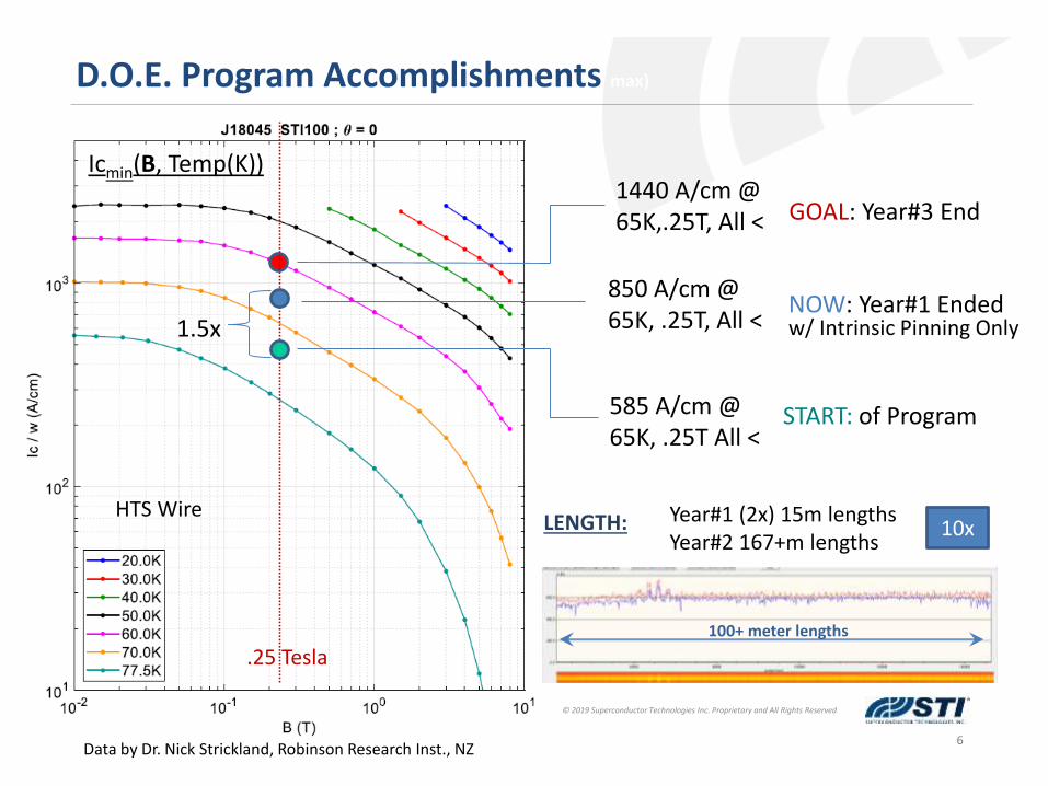
D.O.E. Program Accomplishments max)
850 A/cm @ 65K, .25T, All <
1440 A/cm @ 65K,.25T, All <
585 A/cm @ 65K, .25T All <
START: of Program
NOW: Year#1 Ended
GOAL: Year#3 End
HTS Wire
100+ meter lengths
Year#1 (2x) 15m lengthsYear#2 167+m lengths
10x
Icmin(B, Temp(K))
LENGTH:
w/ Intrinsic Pinning Only
Data by Dr. Nick Strickland, Robinson Research Inst., NZ
.25 Tesla
1.5x
7
© 2019 Superconductor Technologies Inc. Proprietary and All Rights Reserved
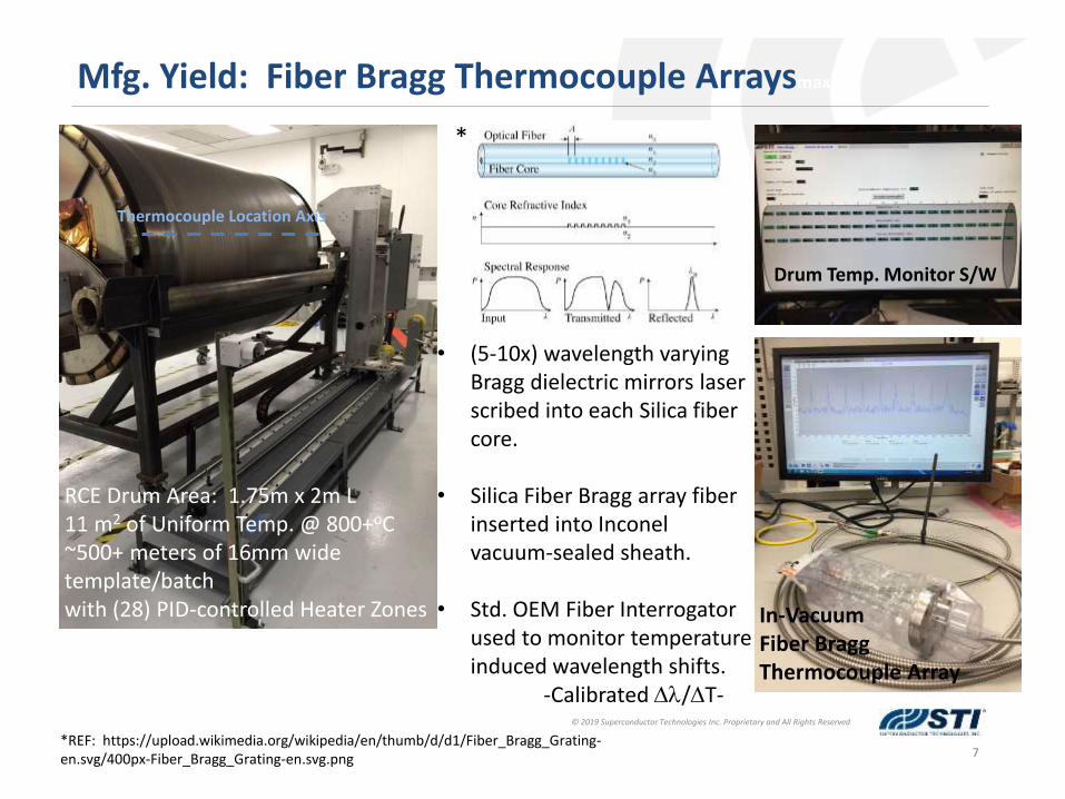
Mfg. Yield: Fiber Bragg Thermocouple Arraysmax)
RCE Drum Area: 1.75m x 2m L11 m2 of Uniform Temp. @ 800+oC~500+ meters of 16mm wide template/batchwith (28) PID-controlled Heater Zones
• (5-10x) wavelength varying Bragg dielectric mirrors laser scribed into each Silica fiber core.
• Silica Fiber Bragg array fiber inserted into Inconel vacuum-sealed sheath.
• Std. OEM Fiber Interrogator used to monitor temperature induced wavelength shifts.
-Calibrated Dl/DT-
Drum Temp. Monitor S/W
In-Vacuum Fiber BraggThermocouple Array
Thermocouple Location Axis
*REF: https://upload.wikimedia.org/wikipedia/en/thumb/d/d1/Fiber_Bragg_Grating-en.svg/400px-Fiber_Bragg_Grating-en.svg.png
*

8
© 2019 Superconductor Technologies Inc. Proprietary and All Rights Reserved
Mfg. Yield: Fiber Bragg Thermocouple Arraysmax)
-60
-55
-50
-45
-40
-35
-30
-25
-20
1490 1510 1530 1550 1570 1590
dB
m
l / nm
𝑻 𝝀 = 𝒄𝟑 ∙𝝀 − 𝝀𝑹𝒆𝒇
𝝀𝑹𝒆𝒇
𝟑
+ 𝒄𝟐 ∙𝝀 − 𝝀𝑹𝒆𝒇
𝝀𝑹𝒆𝒇
𝟐
+ 𝒄𝟏 ∙𝝀 − 𝝀𝑹𝒆𝒇
𝝀𝑹𝒆𝒇+ 𝒄𝟎
T – Temperature [°C]; l – measured Wavelength [nm]
1500-1600nmOptical FiberInterrogator
Step-Response Testing – All (28) Htr. Zones-Determination of ‘cross-talk’ for heater zones -Compared fiber Bragg step responses to thermocouple responses during testing. Offsets-Validated sensitivity to changing drum emissivity during coating processes.-Long-term reliability a concern…(1) failure!
9
© 2019 Superconductor Technologies Inc. Proprietary and All Rights Reserved
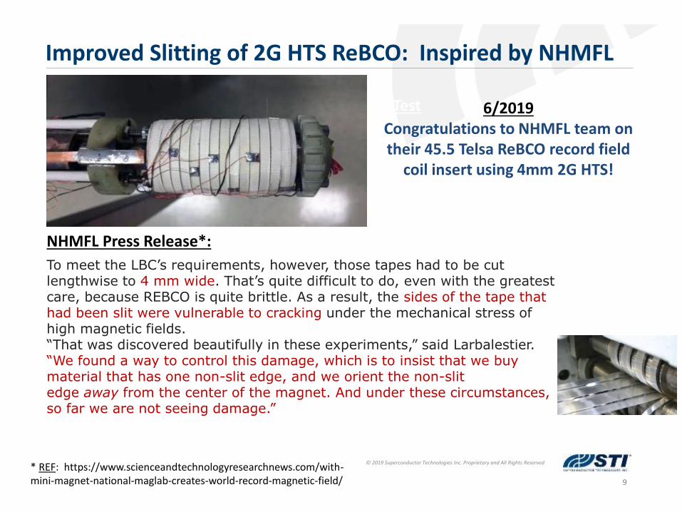
Improved Slitting of 2G HTS ReBCO: Inspired by NHMFL
Wrap (Bi-Axial) Tensile Test
To meet the LBC’s requirements, however, those tapes had to be cut lengthwise to 4 mm wide. That’s quite difficult to do, even with the greatest care, because REBCO is quite brittle. As a result, the sides of the tape that had been slit were vulnerable to cracking under the mechanical stress of high magnetic fields.“That was discovered beautifully in these experiments,” said Larbalestier. “We found a way to control this damage, which is to insist that we buy material that has one non-slit edge, and we orient the non-slit edge away from the center of the magnet. And under these circumstances, so far we are not seeing damage.”
* REF: https://www.scienceandtechnologyresearchnews.com/with-mini-magnet-national-maglab-creates-world-record-magnetic-field/
6/2019Congratulations to NHMFL team on their 45.5 Telsa ReBCO record field
coil insert using 4mm 2G HTS!
NHMFL Press Release*:

10
© 2019 Superconductor Technologies Inc. Proprietary and All Rights Reserved
Slitting Sample Comparison: Laser vs. Mechanical
Samples A,B,C:1064nm Fiber-Laser slit from middle of a 16mm wide ReBCO x 65mm thick substrateSilver-coated
Samples D,E,F:Mechanical slit from middle of a 16mm wide ReBCO x 65mm thick substrateSilver-coated
ALL samples were cut from the same continuous piece of 2G HTS ReBCO tape.
Laser Slit – Thru Backside
Mechanical Slit – Edges UP
16mm Center Cut - 4mm
Laser Mechanical

11
© 2019 Superconductor Technologies Inc. Proprietary and All Rights Reserved
Mechanical SlitLaser Slit – slightly more edge area affected
Slitting Sample Edge Data: Laser vs. Mechanical
60-80mm Damage/Ag-Melt from Edge115-135mm Heat Affected Zone (HAZ)
50-65mm Edge Damage from slit

12
© 2019 Superconductor Technologies Inc. Proprietary and All Rights Reserved
Mechanical Slit Laser Slit
Ic Data: Laser vs. Mechanical
1st Try – Max. alignment Errors
3rd Try – fewer alignment Errors
~200 A/4mm width
• Achieved Laser Slit Ic values 95% of Best-Known Mechanical Slitting technique• MECHANICAL: ~220 A/4mm • LASER: ~210 A/4mm• Our best performance to-date on 65mm Hastelloy substrate w/ 3+mm ReBCO
• Laser cutting speeds (~50mm/sec/line)• i.e. (5) cut-lines 10mm/sec
• Need to reduce the Heat Affected Zone• Need to minimize spot size & foil ‘flatness’ in cut zone to achieve EQUAL performance.
Better AlignmentFewer Dropouts
Alignment Errors

13
© 2019 Superconductor Technologies Inc. Proprietary and All Rights Reserved
22mm f
Slitting Improvements for 2G HTS ReBCO
(1)-meter length
• STI characterized extent of laser slit edge damage with Optical & Laser confocal microscopes after silver removed via chemical etchant. • Could not easily measure edge defect features on laser slit
samples past melt-edge• TEM/SEM/Other techniques may be useful here?
• Many possible Laser configurations…just started w/ off-the-shelf technology for testing.
Next Steps:• Complete multiple 1.0m long wrap-tests with statistical Ic
degradation analyses to determine effects of Bi-Axial stress and compare to best Mechanical Slits.• 1st need to remove alignment induced cracks with improved
fixturing.• Multiple Batches, multiple film thickness, etc..
STI’s Goal: Better processing technology for higher yields & stronger/more-robust 2G HTS.

14
© 2019 Superconductor Technologies Inc. Proprietary and All Rights Reserved
2G HTS Metrology: Speeding-up performance characterization
(1)-meter Length
Investigating ways to characterize the critical surface of 2G HTS by length• Very High Speed sensing• Multi-Pass per condition (B, Temp, Field < +/-90o)
-or-• Multi-Condition per fixed position (B, Temp, Field < +/-90o)• Measures flux expulsion (Meissner Effect) & flux pinning (Abrikosov)• Works at 77K LN2 (1 atm.)65K LN2(0.2 atm.)• Self-Field to 1.5+ Tesla , possibly higher
Concept: A low-power COB LED array w/ Magneto-Optics ‘stack’ on top• <50milliWatts power dissipation in LN2. [36V/.001 Amps]• >=25mmF illumination area for 16mm wide 2G HTS measurements
Top Polarizer 2.5mm Magneto-Optic crystal Bottom Polarizer LED Array NdFeB Permanent Magnet
*
*Ref: https://cdn.comsol.com/wordpress/2017/03/critical-surface-plot.png
Optical stack cost <$1k

15
© 2019 Superconductor Technologies Inc. Proprietary and All Rights Reserved
22mm Diameter
2G HTS Metrology
(1)-meter Length
Illuminated TOP View #1 TOP View #2 Room TempIn-Air Testing
B-Field ‘shadow’visible
• Verdet constant increases with lower wavelengths & lower operating temp’s. • Polarization rotation increases with higher Verdet constant & higher B-fields.• - Should work better @(77K) cryogenic temps & 0.5 to 2 Tesla.• COB LED array has performed well with >50x LN2 immersions Room Temp.• NdFeB Permanent magnet field (~0.3-0.5) Tesla, in region-of-interest• Height Magnet to M.O. crystal = <3.0mm, small air gap/retain high flux density
*REF: https://matesy.de/en/products/materials/mo-sensors-magnetooptics
MAGNETMAGNET
*

16
© 2019 Superconductor Technologies Inc. Proprietary and All Rights Reserved
22mm Diameter
2G HTS Metrology
Several possible modes of operation:Backlit Illumination Mode
Magnet Side: Flux expulsion region @ edge of tape is
clearly illuminated
MAGNET
Non-Magnet Side: No ‘shadow’ or ‘ring’ visible
COB LED Array
Next Steps: -CCD camera & Image processing software for data collection-Determine Statistical correlation to D.C. Ic values
-Area & Light intensity-
77K LN2 Testing

For information on Superconductor Technologies’ Conductustm
2G HTS wire please contact; Adam Shelton , [E]: [email protected]