Cryogenic Measurements of Surface Mount Multi-layer ... · PDF fileCryogenic Measurements of...
37
NATIONAL RADIO ASTRONOMY OBSERVATORY Green Bank, West Virginia ELECTRONICS DIVISION TECHNICAL NOTE NO. 214 Cryogenic Measurements of Surface Mount Multi-layer Ceramic Chip Capacitors Roger D. Norrod November 10, 2009 Rev. March 9, 2010
Transcript of Cryogenic Measurements of Surface Mount Multi-layer ... · PDF fileCryogenic Measurements of...
NATIONAL RADIO ASTRONOMY OBSERVATORY Green Bank, West Virginia
ELECTRONICS DIVISION TECHNICAL NOTE NO. 214
Cryogenic Measurements of Surface Mount Multi-layer Ceramic Chip Capacitors
Roger D. Norrod
November 10, 2009 Rev. March 9, 2010
NATIONAL RADIO ASTRONOMY OBSERVATORY POST OFFICE 2 GREEN BANK WV 24944-0002 TELEPHONE 304-456-2011 FAX 304-456-2229
Cryogenic Measurements of Surface Mount
Multi-layer Ceramic Chip Capacitors
Roger D. Norrod November 9, 2009
1 Introduction EDTN 205 reported cryogenic measurements (4K) of several chip capacitors and resistors[1]. Most of the devices tested for that report were designed for use in wire-bonded assemblies, i.e. were single-layer or other vertically oriented packages. Other researchers have published capacitor cryogenic test results[2]. This document reports on cryogenic tests of other types of chip capacitors, namely inexpensive, commonly available surface mount units in industry standard packages. For array receivers where costs are a significant concern, it will be advantageous if devices from several manufacturers are available for use in circuit designs, and surface mount rather than wirebond assembly techniques can be used. All of the types were tested to 77K by dipping in liquid nitrogen and most to less than 20K using a closed-cycle refrigerator. The EIA has defined several classes of dielectric for use in capacitors; a Class 2, X5R (X5R signifies the allowed capacitance change over temperature, ±15% over -55 to +85˚C) sample was first tested and found to exhibit unacceptable capacitance change. The remaining samples tested were Class 1, C0G/NP0 types (0±30ppm/˚C over -55 to 125˚C). The units to test were selected by simply picking types available from stock from Digikey[3] in both large and small quantities (cut-tape) and in a wide range of values in the 0402 case size. It was found that C0G/NP0 units from four manufacturers functioned quite well below 20K. The liquid nitrogen dip tests were found to be good indication of 20K performance because little or no change in capacitance was observed between 77K and 20K. 2 Test Setup and Procedure The capacitor types tested are listed in Table 1, along with the available capacitance range in the 0402 size for reference. The Murata GRM is available in a wider range of capacitance but the specified Q is rather low (Q ≥ 1000 at 1MHz for C≥30pF) and this type may not be appropriate for some microwave applications. The other three types are available in larger values in larger case sizes.
1
2
Table 1 Capacitor Manufacturers and Range
Type 0402 Range Available
AVX U Series 1-30 pF Johanson S Series 0.2-33 pF
Murata GRM Series 0.5-1000 pF Panasonic ECD Series 0.1-15 pF
To measure capacitance, a HP4275A LCR variable frequency meter set to 1MHz test frequency was used. The capacitor sample to be tested was mounted on a microstrip circuit in a test block, between a short 50Ω line and a pad with several ground vias. The 50Ω line connected to a coaxial K-connector. For the liquid nitrogen dip tests, a 14 inch length of 141 stainless cable connected to the HP4275A. For the refrigerated tests, a NRAO low-loss stainless airline connected to the test dewar wall, and then 30 inches of Belden 1673A flexible coax to the HP4275A. In both cases, the HP4275A was zeroed with no capacitor mounted (the 50Ω microstrip line open-circuited). After a few hours of 4275A warm-up, little drift was seen but the zero process was done at least once each day. Testing was limited to measuring capacitance change; other capacitor characteristics were not evaluated. It should be noted the test setup capacitance readings are consistently 20-25% higher than expected from the capacitors’ marked values. The cause of this is currently unknown. 3 Results Table 2 contains the 77K liquid nitrogen dip test results. For each sample, a Styrofoam cup was filled with liquid nitrogen, and the test block connected to the stainless steel coax was plunged into the nitrogen and allowed to stabilize. The percent change is defined relative to the room temperature value.
Table 2 Liquid Nitrogen Dip Test Results
ID Type 300K Value
77K Value
% Change
1 Panasonic ECJ-0EB1A473K, 47,000pF, X5R 63700pF 13500pF -79 2 Panasonic ECD-G0E100C, 10pF, 25V, C0G, #1 12.2 12.3 +0.8 3 Panasonic ECD-G0E100C, 10pF, 25V, C0G, #2 12.4 12.3 -0.8 4 AVX 0402U100JAT2A, 10pF, 50V, NP0, #1 11.7 12.0 +2.6 5 AVX 0402U100JAT2A, 10pF, 50V, NP0, #2 12.3 12.6 +2.4 6 Johanson 500R07S100GV4T, 10pF, 50V, C0G, #1 12.6 12.8 +1.6 7 Johanson 500R07S100GV4T, 10pF, 50V, C0G, #2 12.7 13.0 +2.4 8 Murata GRM1555C1H471JA01D, 470pF, 50V, C0G 594.5 597.0 +0.4 Tables 3-6 contain results for the closed-cycle refrigerator tests. The approximate 2 hour cool down time gave the opportunity to record capacitance at a few intermediate temperatures. The capacitance varied smoothly with no unusual changes noted.

3
Table 3 Refrigerated Test Results
Type Panasonic ECD-G0E100C Temperature (K) C (pF) %Change Time
294 10.3 -- 08:06 248 10.3 0.0 08:30 149 10.2 -1.0 09:05 16 10.1 -1.9 09:53
Table 4 Refrigerated Test Results
Type Johanson 500R07S100GV4T Temperature (K) C (pF) %Change Time
294 13.0 -- 14:30 243 13.0 0.0 14:55 197 13.0 0.0 15:10 164 13.0 0.0 107 13.1 0.8 15:40 78 13.2 1.5 15:46 18 13.3 2.3 15:55
Table 5 Refrigerated Test Results
Type AVX 04025U100JAT2A Temperature (K) C (pF) %Change Time
295 12.2 -- 11:00 238 12.0 -1.6 11:26 179 11.9 -2.6 11:48 77 11.8 -3.3 12:15 17 11.9 -2.6 12:43
Table 6
Refrigerated Test Results Type Murata GRM1555C1H471JA01D
Temperature (K) C (pF) %Change Time 295 575.8 -- 14:25 250 576.2 0.0 14:48 207 576.7 0.2 15:03 192 576.9 0.2 15:07 157 577.4 0.3 15:20 99 577.5 0.3 15:36 77 576.9 0.2 15:41 50 576.5 0.1 15:45 16 575.5 -0.0 16:10
4
4 Summary Multilayer ceramic chip capacitors with C0G/NP0 rated temperature coefficients from four manufacturers were tested at temperatures to less than 20K and found to function with less than a few percent change in value from room temperature. The capacitors tested are currently available at low cost in either large or small quantities and in a wide range of values, and are designed for surface mounting by hand or reflow soldering. All the units tested were in the EIA 0402 (0.040 X 0.020 inch footprint) package, although other size packages in the same series are available. Percentage wise, the Panasonic ECD and Murata types change the least over the temperature range tested. The manufacturer’s data sheets do not provide any information about the ceramic formulations in their capacitors, but the Murata type likely has significantly different dielectric constant than the others in order to achieve the larger values in the same 0402 envelope. The liquid nitrogen dip tests were found to be a good indication of 20K performance; little or no change in capacitance was observed between 77K and 15K. 5 Acknowledgement Thanks to Bob Simon for providing the microstrip test fixture and doing the assembly work. 6 References
1. A.R. Kerr and M. Lambeth, NRAO EDTN 205, “Cryogenic (4K) Measurements of Some Resistors and Capacitors”, March 5, 2007.
2. Joseph C. Bardin, “Silicon-Germanium Heterojunction Bipolar Transistors For Extremely
Low-Noise Applications”, PhD Thesis, California Institute of Technology, Pasadena, CA, pp 154-155, May 2009.
3. http://www.digikey.com
5
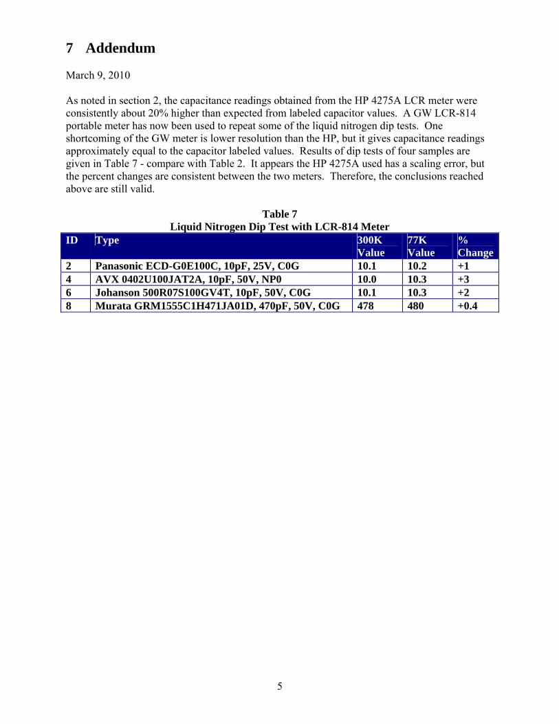
7 Addendum March 9, 2010 As noted in section 2, the capacitance readings obtained from the HP 4275A LCR meter were consistently about 20% higher than expected from labeled capacitor values. A GW LCR-814 portable meter has now been used to repeat some of the liquid nitrogen dip tests. One shortcoming of the GW meter is lower resolution than the HP, but it gives capacitance readings approximately equal to the capacitor labeled values. Results of dip tests of four samples are given in Table 7 - compare with Table 2. It appears the HP 4275A used has a scaling error, but the percent changes are consistent between the two meters. Therefore, the conclusions reached above are still valid.
Table 7 Liquid Nitrogen Dip Test with LCR-814 Meter
ID Type 300K Value
77K Value
% Change
2 Panasonic ECD-G0E100C, 10pF, 25V, C0G 10.1 10.2 +1 4 AVX 0402U100JAT2A, 10pF, 50V, NP0 10.0 10.3 +3 6 Johanson 500R07S100GV4T, 10pF, 50V, C0G 10.1 10.3 +2 8 Murata GRM1555C1H471JA01D, 470pF, 50V, C0G 478 480 +0.4

6
APPENDIX
Capacitor Data Sheets

RF/Microwave C0G (NP0) Capacitors (RoHS)Ultra Low ESR, “U” Series, C0G (NP0) Chip Capacitors
8
A
B
D DE
C
A
B C
A
B
D DE
C
A
B
D DE
C
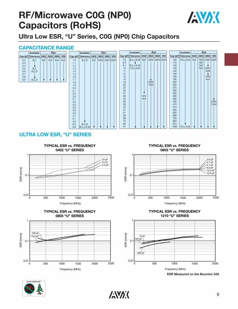
GENERAL INFORMATION“U” Series capacitors are C0G (NP0) chip capacitors spe -cially designed for “Ultra” low ESR for applications in thecommunications market. Max ESR and effective capacitance
are met on each value producing lot to lot uniformity.Sizes available are EIA chip sizes 0603, 0805, and 1210.
Size A B C D E0402 0.039±0.004 (1.00±0.1) 0.020±0.004 (0.50±0.1) 0.024 (0.6) max N/A N/A0603 0.060±0.010 (1.52±0.25) 0.030±0.010 (0.76±0.25) 0.036 (0.91) max 0.010±0.005 (0.25±0.13) 0.030 (0.76) min0805 0.079±0.008 (2.01±0.2) 0.049±0.008 (1.25±0.2) 0.040±0.005 (1.02±0.127) 0.020±0.010 (0.51±0.255) 0.020 (0.51) min1210 0.126±0.008 (3.2±0.2) 0.098±0.008 (2.49±0.2) 0.050±0.005 (1.27±0.127) 0.025±0.015 (0.635±0.381) 0.040 (1.02) min
ELECTRICAL CHARACTERISTICSCapacitance Values and Tolerances:
Size 0402 - 0.2 pF to 22 pF @ 1 MHzSize 0603 - 1.0 pF to 100 pF @ 1 MHzSize 0805 - 1.6 pF to 160 pF @ 1 MHzSize 1210 - 2.4 pF to 1000 pF @ 1 MHz
Temperature Coefficient of Capacitance (TC):0±30 ppm/°C (-55° to +125°C)
Insulation Resistance (IR):1012 Ω min. @ 25°C and rated WVDC1011 Ω min. @ 125°C and rated WVDC
Working Voltage (WVDC):Size Working Voltage0402 - 50, 25 WVDC0603 - 200, 100, 50 WVDC0805 - 200, 100 WVDC1210 - 200, 100 WVDC
Dielectric Working Voltage (DWV):250% of rated WVDC
Equivalent Series Resistance Typical (ESR):0402 - See Performance Curve, page 90603 - See Performance Curve, page 90805 - See Performance Curve, page 91210 - See Performance Curve, page 9
Marking: Laser marking EIA J marking standard (except 0603) (capacitance code andtolerance upon request).
MILITARY SPECIFICATIONSMeets or exceeds the requirements of MIL-C-55681
0805
Case Size0402060308051210
1
VoltageCode
3 = 25V5 = 50V1 = 100V2 = 200V
U
Dielectric =Ultra Low
ESR
100
Capacitance
J
CapacitanceTolerance
CodeB = ±0.1pFC = ±0.25pFD = ±0.5pFF = ±1%G = ±2%J = ±5%K = ±10%M = ±20%
A
Failure RateCode
A = Not Appli-cable
T
Termination T= Plated Ni
and Sn
2
PackagingCode
A
SpecialCode
A = Standard
HOW TO ORDER
EIA Capacitance Code in pF.
First two digits = significant figuresor “R” for decimal place.
Third digit = number of zeros or after“R” significant figures.
2 = 7" Reel 4 = 13" Reel9 = Bulk
DIMENSIONS: inches (millimeters)
0402 0603 0805 1210
inches (mm)
NOTE: Contact factory for availability of Termination and Toler-ance Options for Specific Part Numbers.
RoHS COMPLIANT
Pb: Free
RF/Microwave C0G (NP0) Capacitors (RoHS)Ultra Low ESR, “U” Series, C0G (NP0) Chip Capacitors
9
3.9 pF4.7 pF5.1 pF6.8 pF10.0 pF15.0 pF
1
0.1
0.010 500 1000 1500 2000 2500
Frequency (MHz)
ES
R (o
hms)
TYPICAL ESR vs. FREQUENCY0603 “U” SERIES
10 pF15 pF3.3 pF
1
0.1
0.010 500 1000 1500 2000 2500
Frequency (MHz)
ES
R (o
hms)
TYPICAL ESR vs. FREQUENCY0402 “U” SERIES
10.0 pF100 pF
1
0.1
0.010 500 1000 1500 2000 2500
Frequency (MHz)
ES
R (o
hms)
TYPICAL ESR vs. FREQUENCY0805 “U” SERIES
10 pF100 pF
300 pF
1
0.1
0.010 500 1000 1500 2000
Frequency (MHz)
ES
R (o
hms)
TYPICAL ESR vs. FREQUENCY1210 “U” SERIES
CAPACITANCE RANGE
ULTRA LOW ESR, “U” SERIES
ESR Measured on the Boonton 34A
Available SizeCap (pF) Tolerance 0402 0603 0805 1210
0.2 B,C 50V N/A N/A N/A0.30.40.5 B,C0.6 B,C,D0.70.80.9 B,C,D
Available SizeCap (pF) Tolerance 0402 0603 0805 1210
1.0 B,C,D 50V 200V 200V 200V1.11.21.31.41.51.61.71.81.92.02.12.22.42.73.03.33.63.94.34.75.15.66.2 B,C,D6.8 B,C,J,K,M
Available SizeCap (pF) Tolerance 0402 0603 0805 1210
7.5 B,C,J,K,M 50V 200V 200V 200V8.29.1 B,C,J,K,M10 F,G,J,K,M1112131518 200V20 100V22242730 50V33 N/A36394347515668758291
Available SizeCap (pF) Tolerance 0402 0603 0805 1210
100 F,G,J,K,M N/A 100V 200V 200V110 50V120 50V130 N/A 200V140 100V150160 100V180 N/A200220270300330360390430 200V470 100V510560620680750820910
1000 F,G,J,K,M
RoHS COMPLIANT
Pb: Free

RF/Microwave C0G (NP0) CapacitorsUltra Low ESR, “U” Series, C0G (NP0) Chip Capacitors
TY
PIC
AL
SE
RIE
S R
ES
ON
AN
T F
RE
QU
EN
CY
“U”
SE
RIE
S C
HIP
1210
0805
0603
0402
10 1.0
0.1 1.
010
100
1000
Cap
acita
nce
(pF)
Frequency (GHz)
10
RF/Microwave C0G (NP0) Capacitors (Sn/Pb)Ultra Low ESR, “U” Series, C0G (NP0) Chip Capacitors
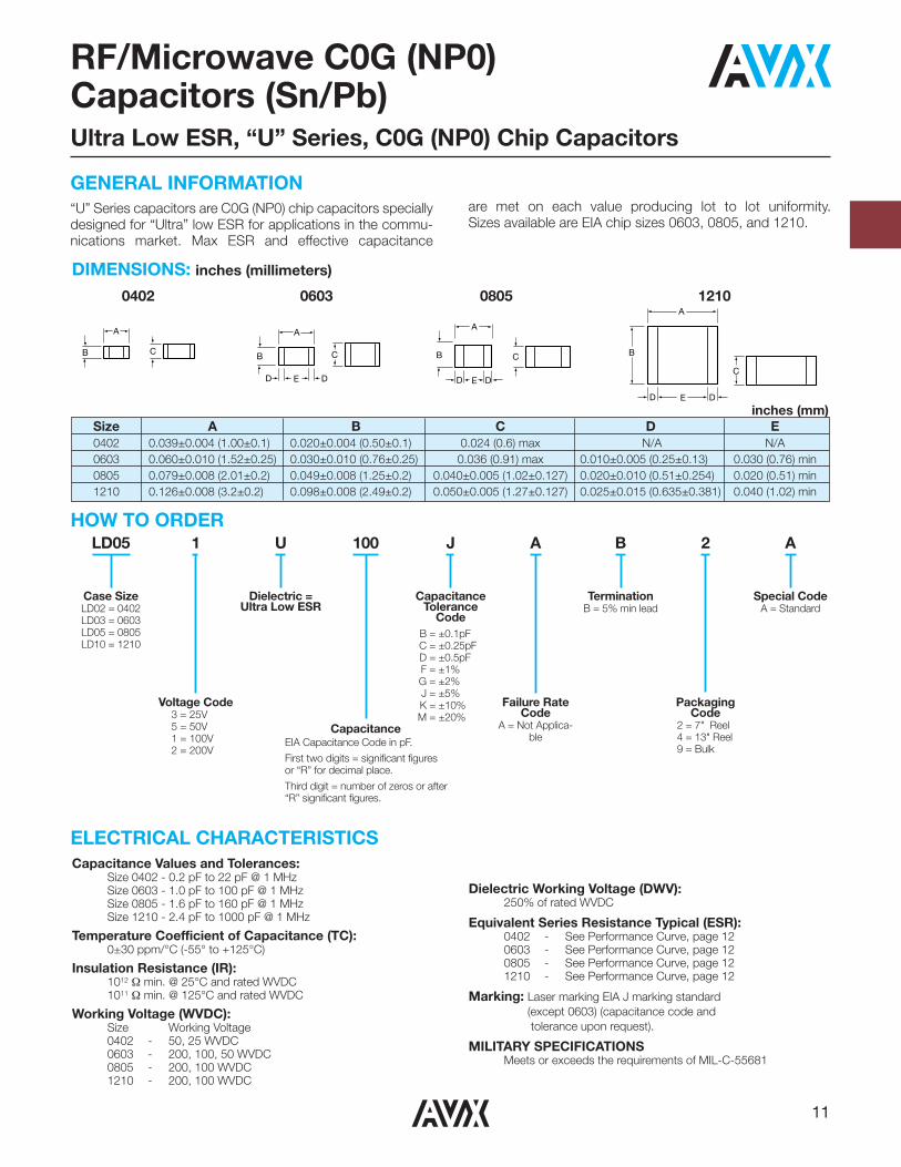
GENERAL INFORMATION“U” Series capacitors are C0G (NP0) chip capacitors speciallydesigned for “Ultra” low ESR for applications in the commu-nications market. Max ESR and effective capacitance
are met on each value producing lot to lot uniformity.Sizes available are EIA chip sizes 0603, 0805, and 1210.
Size A B C D E0402 0.039±0.004 (1.00±0.1) 0.020±0.004 (0.50±0.1) 0.024 (0.6) max N/A N/A0603 0.060±0.010 (1.52±0.25) 0.030±0.010 (0.76±0.25) 0.036 (0.91) max 0.010±0.005 (0.25±0.13) 0.030 (0.76) min0805 0.079±0.008 (2.01±0.2) 0.049±0.008 (1.25±0.2) 0.040±0.005 (1.02±0.127) 0.020±0.010 (0.51±0.254) 0.020 (0.51) min1210 0.126±0.008 (3.2±0.2) 0.098±0.008 (2.49±0.2) 0.050±0.005 (1.27±0.127) 0.025±0.015 (0.635±0.381) 0.040 (1.02) min
Capacitance Values and Tolerances:Size 0402 - 0.2 pF to 22 pF @ 1 MHzSize 0603 - 1.0 pF to 100 pF @ 1 MHzSize 0805 - 1.6 pF to 160 pF @ 1 MHzSize 1210 - 2.4 pF to 1000 pF @ 1 MHz
Temperature Coefficient of Capacitance (TC):0±30 ppm/°C (-55° to +125°C)
Insulation Resistance (IR):1012 Ω min. @ 25°C and rated WVDC1011 Ω min. @ 125°C and rated WVDC
Working Voltage (WVDC):Size Working Voltage0402 - 50, 25 WVDC0603 - 200, 100, 50 WVDC0805 - 200, 100 WVDC1210 - 200, 100 WVDC
Dielectric Working Voltage (DWV):250% of rated WVDC
Equivalent Series Resistance Typical (ESR):0402 - See Performance Curve, page 120603 - See Performance Curve, page 120805 - See Performance Curve, page 121210 - See Performance Curve, page 12
Marking: Laser marking EIA J marking standard (except 0603) (capacitance code andtolerance upon request).
MILITARY SPECIFICATIONSMeets or exceeds the requirements of MIL-C-55681
A
B
D DE
C
A
B C
A
B
D DE
C
A
B
D DE
C
LD05
Case SizeLD02 = 0402LD03 = 0603LD05 = 0805LD10 = 1210
1
Voltage Code3 = 25V5 = 50V1 = 100V2 = 200V
U
Dielectric =Ultra Low ESR
100
Capacitance
J
CapacitanceTolerance
CodeB = ±0.1pFC = ±0.25pFD = ±0.5pFF = ±1%G = ±2%J = ±5%K = ±10%M = ±20%
A
Failure RateCode
A = Not Applica-ble
B
Termination B = 5% min lead
2
PackagingCode
2 = 7" Reel 4 = 13" Reel9 = Bulk
A
Special CodeA = Standard
HOW TO ORDER
EIA Capacitance Code in pF.
First two digits = significant figuresor “R” for decimal place.
Third digit = number of zeros or after“R” significant figures.
DIMENSIONS: inches (millimeters)
0402 0603 0805 1210
inches (mm)
ELECTRICAL CHARACTERISTICS
11
ULTRA LOW ESR, “U” SERIES
3.9 pF4.7 pF5.1 pF6.8 pF10.0 pF15.0 pF
1
0.1
0.010 500 1000 1500 2000 2500
Frequency (MHz)
ES
R (o
hms)
TYPICAL ESR vs. FREQUENCY0603 “U” SERIES
10 pF15 pF3.3 pF
1
0.1
0.010 500 1000 1500 2000 2500
Frequency (MHz)
ES
R (o
hms)
TYPICAL ESR vs. FREQUENCY0402 “U” SERIES
10.0 pF100 pF
1
0.1
0.010 500 1000 1500 2000 2500
Frequency (MHz)
ES
R (o
hms)
TYPICAL ESR vs. FREQUENCY0805 “U” SERIES
10 pF100 pF
300 pF
1
0.1
0.010 500 1000 1500 2000
Frequency (MHz)
ES
R (o
hms)
TYPICAL ESR vs. FREQUENCY1210 “U” SERIES
ESR Measured on the Boonton 34A
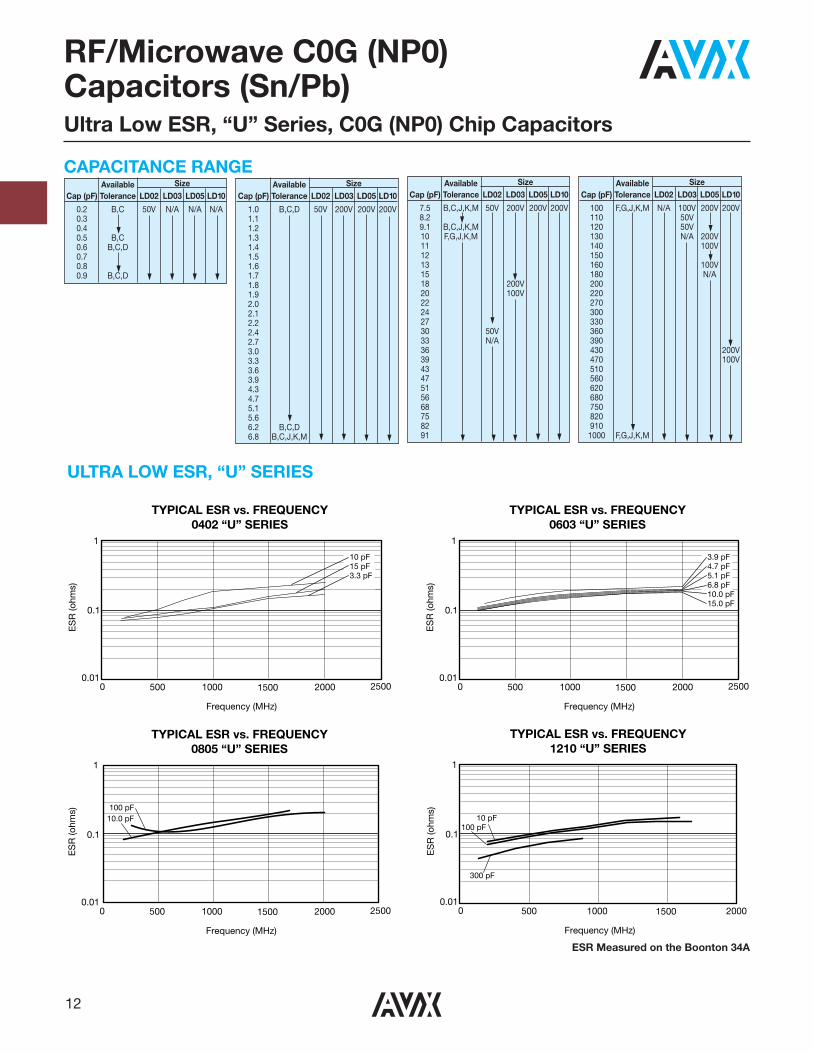
RF/Microwave C0G (NP0) Capacitors (Sn/Pb)Ultra Low ESR, “U” Series, C0G (NP0) Chip Capacitors
CAPACITANCE RANGEAvailable Size
Cap (pF) Tolerance LD02 LD03 LD05 LD10
0.2 B,C 50V N/A N/A N/A0.30.40.5 B,C0.6 B,C,D0.70.80.9 B,C,D
Available SizeCap (pF) Tolerance LD02 LD03 LD05 LD10
1.0 B,C,D 50V 200V 200V 200V1.11.21.31.41.51.61.71.81.92.02.12.22.42.73.03.33.63.94.34.75.15.66.2 B,C,D6.8 B,C,J,K,M
Available SizeCap (pF) Tolerance LD02 LD03 LD05 LD10
7.5 B,C,J,K,M 50V 200V 200V 200V8.29.1 B,C,J,K,M10 F,G,J,K,M1112131518 200V20 100V22242730 50V33 N/A36394347515668758291
Available SizeCap (pF) Tolerance LD02 LD03 LD05 LD10
100 F,G,J,K,M N/A 100V 200V 200V110 50V120 50V130 N/A 200V140 100V150160 100V180 N/A200220270300330360390430 200V470 100V510560620680750820910
1000 F,G,J,K,M
12
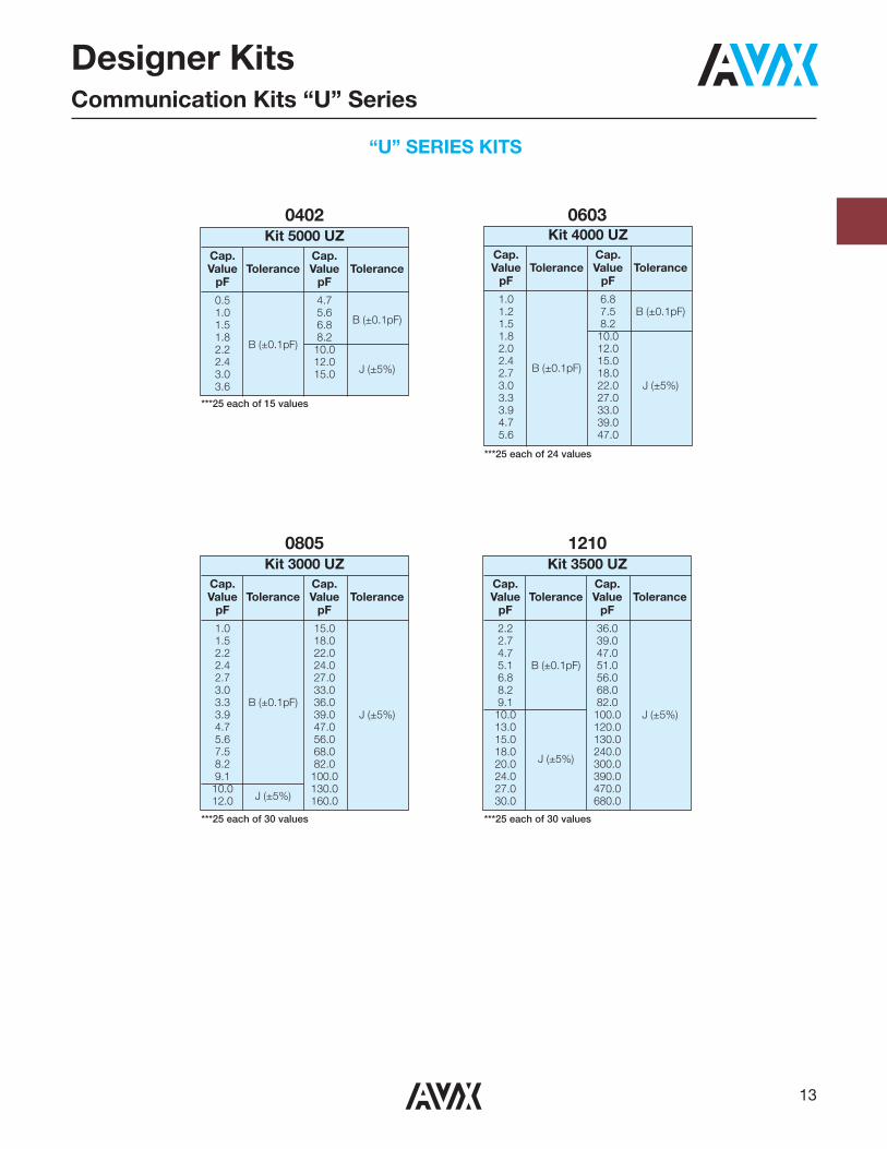
“U” SERIES KITS
Designer KitsCommunication Kits “U” Series
0402 0603Kit 4000 UZ
Cap. Cap.Value Tolerance Value Tolerance
pF pF
1.0 6.81.2 7.5 B (±0.1pF)1.5 8.21.8 10.02.0 12.02.4
B (±0.1pF)15.0
2.7 18.03.0 22.0 J (±5%)3.3 27.03.9 33.04.7 39.05.6 47.0
***25 each of 24 values
***25 each of 15 values
Kit 5000 UZCap. Cap.Value Tolerance Value Tolerance
pF pF
0.5 4.71.0 5.6
B (±0.1pF)1.5 6.81.8
B (±0.1pF)8.2
2.2 10.02.4 12.0
J (±5%)3.0 15.03.6
0805
***25 each of 30 values
Kit 3000 UZCap. Cap.Value Tolerance Value Tolerance
pF pF
1.0 15.01.5 18.02.2 22.02.4 24.02.7 27.03.0 33.03.3 B (±0.1pF) 36.03.9 39.0 J (±5%)4.7 47.05.6 56.07.5 68.08.2 82.09.1 100.0
10.0J (±5%)
130.012.0 160.0
1210
***25 each of 30 values
Kit 3500 UZCap. Cap.Value Tolerance Value Tolerance
pF pF
2.2 36.02.7 39.04.7 47.05.1 B (±0.1pF) 51.06.8 56.08.2 68.09.1 82.010.0 100.0 J (±5%)13.0 120.015.0 130.018.0
J (±5%)240.0
20.0 300.024.0 390.027.0 470.030.0 680.0
13
7www.johansontechnology.comwww.johansontechnology.com
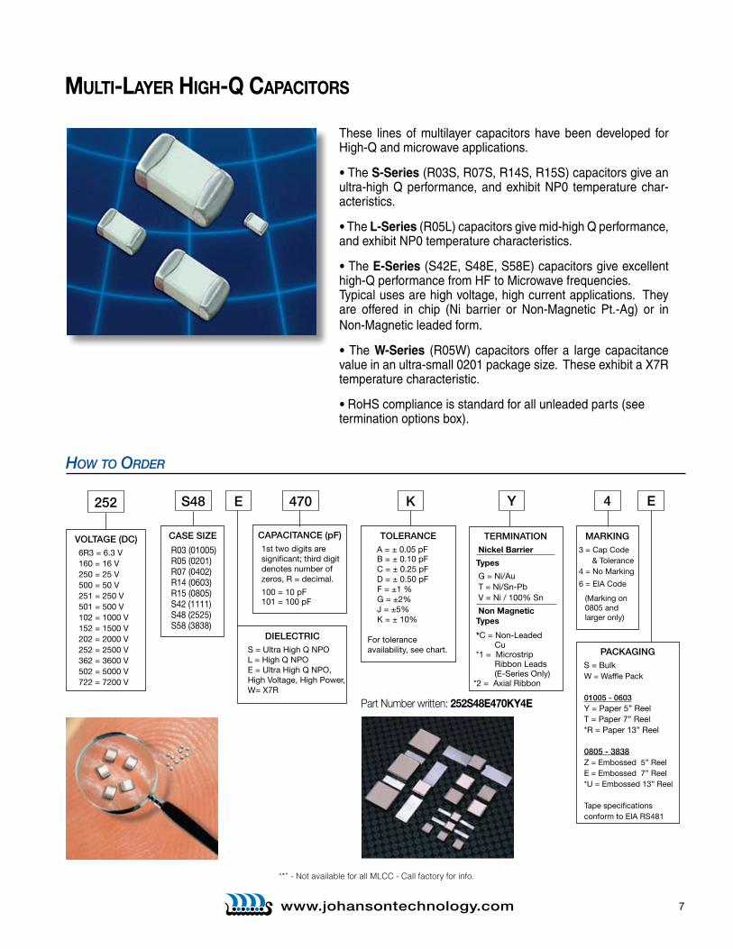
These lines of multilayer capacitors have been developed for High-Q and microwave applications.
• The S-Series (R03S, R07S, R14S, R15S) capacitors give an ultra-high Q performance, and exhibit NP0 temperature char-acteristics.
• The L-Series (R05L) capacitors give mid-high Q performance, and exhibit NP0 temperature characteristics.
• The E-Series (S42E, S48E, S58E) capacitors give excellent high-Q performance from HF to Microwave frequencies. Typical uses are high voltage, high current applications. They are offered in chip (Ni barrier or Non-Magnetic Pt.-Ag) or in Non-Magnetic leaded form.
• The W-Series (R05W) capacitors offer a large capacitance value in an ultra-small 0201 package size. These exhibit a X7R temperature characteristic.
• RoHS compliance is standard for all unleaded parts (see termination options box).
Multi-layer HigH-Q CapaCitors
How To order
Part Number written: 252S48E470KY4E
VOLTAGE (DC)6R3 = 6 .3 V160 = 16 V 250 = 25 V500 = 50 V251 = 250 V501 = 500 V102 = 1000 V152 = 1500 V202 = 2000 V252 = 2500 V362 = 3600 V 502 = 5000 V 722 = 7200 V
252
CASE SIZE
R03 (01005) R05 (0201)R07 (0402)R14 (0603)R15 (0805)S42 (1111) S48 (2525) S58 (3838)
S48 470
TOLERANCE A = ± 0 .05 pF B = ± 0 .10 pF C = ± 0 .25 pF D = ± 0 .50 pF
F = ±1 %G = ±2%J = ±5%K = ± 10%
For tolerance availability, see chart .
K
MARKING3 = Cap Code & Tolerance4 = No Marking
6 = EIA Code
(Marking on 0805 and larger only)
4
TERMINATION Nickel Barrier
Types
G = Ni/Au T = Ni/Sn-Pb V = Ni / 100% Sn
Non Magnetic Types
*C = Non-Leaded Cu *1 = Microstrip Ribbon Leads
(E-Series Only)*2 = Axial Ribbon
Y
CAPACITANCE (pF)1st two digits aresignificant; third digitdenotes number ofzeros, R = decimal .
100 = 10 pF101 = 100 pF
PACKAGING S = Bulk
W = Waffle Pack 01005 - 0603 Y = Paper 5” Reel T = Paper 7” Reel *R = Paper 13” Reel 0805 - 3838Z = Embossed 5” ReelE = Embossed 7” Reel*U = Embossed 13” Reel Tape specificationsconform to EIA RS481
E
DIELECTRICS = Ultra High Q NPOL = High Q NPOE = Ultra High Q NPO, High Voltage, High Power, W= X7R
E
“*” - Not available for all MLCC - Call factory for info.
8 www.johansontechnology.com
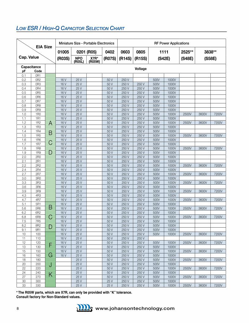
Miniature Size - Portable Electronics RF Power Applications
01005(R03S)
0201 (R05) 0402(R07S)
0603(R14S)
0805(R15S)
1111(S42E)
2525**(S48E)
3838**(S58E)NPO
(R05L)X7R*
(R05W)Capacitance VoltagepF Code0.1 0R1
A
B
C
D
0.2 0R2 16 V 25 V 50 V 250 V 500V 1000V0.3 0R3 16 V 25 V 50 V 250 V 250 V 500V 1000V0.4 0R4 16 V 25 V 50 V 250 V 250 V 500V 1000V0.5 0R5 16 V 25 V 50 V 250 V 250 V 500V 1000V0.6 0R6 16 V 25 V 50 V 250 V 250 V 500V 1000V0.7 0R7 16 V 25 V 50 V 250 V 250 V 500V 1000V0.8 0R8 16 V 25 V 50 V 250 V 250 V 500V 1000V0.9 0R9 16 V 25 V 50 V 250 V 250 V 500V 1000V1.0 1R0 16 V 25 V 50 V 250 V 250 V 500V 1000V 2500V 3600V 7200V1.1 1R1 16 V 25 V 50 V 250 V 250 V 500V 1000V1.2 1R2 16 V 25 V 50 V 250 V 250 V 500V 1000V 2500V 3600V 7200V1.3 1R3 16 V 25 V 50 V 250 V 250 V 500V 1000V1.4 1R4 16 V 25 V 50 V 250 V 250 V 500V 1000V1.5 1R5 16 V 25 V 50 V 250 V 250 V 500V 1000V 2500V 3600V 7200V1.6 1R6 16 V 25 V 50 V 250 V 250 V 500V 1000V1.7 1R7 16 V 25 V 50 V 250 V 250 V 500V 1000V1.8 1R8 16 V 25 V 50 V 250 V 250 V 500V 1000V 2500V 3600V 7200V1.9 1R9 16 V 25 V 50 V 250 V 250 V 500V 1000V2.0 2R0 16 V 25 V 50 V 250 V 250 V 500V 1000V2.1 2R1 16 V 25 V 50 V 250 V 250 V 500V 1000V2.2 2R2 16 V 25 V 50 V 250 V 250 V 500V 1000V 2500V 3600V 7200V2.4 2R4 16 V 25 V 50 V 250 V 250 V 500V 1000V2.7 2R7 16 V 25 V 50 V 250 V 250 V 500V 1000V 2500V 3600V 7200V3.0 3R0 16 V 25 V 50 V 250 V 250 V 500V 1000V3.3 3R3 16 V 25 V 50 V 250 V 250 V 500V 1000V 2500V 3600V 7200V3.6 3R6 16 V 25 V 50 V 250 V 250 V 500V 1000V3.9 3R9 16 V 25 V 50 V 250 V 250 V 500V 1000V 2500V 3600V 7200V4.3 4R3 16 V 25 V 50 V 250 V 250 V 500V 1000V4.7 4R7 16 V 25 V 50 V 250 V 250 V 500V 1000V 2500V 3600V 7200V5.1 5R1
B
C
D
16 V 25 V 50 V 250 V 250 V 500V 1000V5.6 5R6 16 V 25 V 50 V 250 V 250 V 500V 1000V 2500V 3600V 7200V6.2 6R2 16 V 25 V 50 V 250 V 250 V 500V 1000V6.8 6R8 16 V 25 V 50 V 250 V 250 V 500V 1000V 2500V 3600V 7200V7.5 7R5 16 V 25 V 50 V 250 V 250 V 500V 1000V8.2 8R2 16 V 25 V 50 V 250 V 250 V 500V 1000V9.1 9R1 16 V 25 V 50 V 250 V 250 V 500V 1000V10 100
F
G
J
K
16 V 25 V 50 V 250 V 250 V 500V 1000V 2500V 3600V 7200V11 110 16 V 25 V 50 V 250 V 250 V12 120 16 V 25 V 50 V 250 V 250 V 500V 1000V 2500V 3600V 7200V13 130 16 V 25 V 50 V 250 V 250 V 500V 1000V15 150 16 V 25 V 50 V 250 V 250 V 500V 1000V 2500V 3600V 7200V16 160 16 V 25 V 50 V 250 V 250 V 500V 1000V18 180 25 V 50 V 250 V 250 V 500V 1000V 2500V 3600V 7200V20 200 25 V 50 V 250 V 250 V 500V 1000V22 220 25 V 50 V 250 V 250 V 500V 1000V 2500V 3600V 7200V24 240 25 V 50 V 250 V 250 V 500V 1000V27 270 25 V 50 V 250 V 250 V 500V 1000V 2500V 3600V 7200V30 300 25 V 25 V 250 V 250 V 500V 1000V33 330 25 V 25 V 250 V 250 V 500V 1000V 2500V 3600V 7200V
low eSR / HigH-Q CapaCiToR SeleCTion CHaRT
EIA Size
Cap. Value
* The R05W parts, which are X7R, can only be provided with “K” tolerance. Consult factory for Non-Standard values.
9www.johansontechnology.com
Miniature Size - Portable Electronics RF Power Applications
01005(R03S)
0201 (R05) 0402(R07S)
0603(R14S)
0805(R15S)
1111(S42E)
2525**(S48E)
3838**(S58E)NPO
(R05L)X7R*
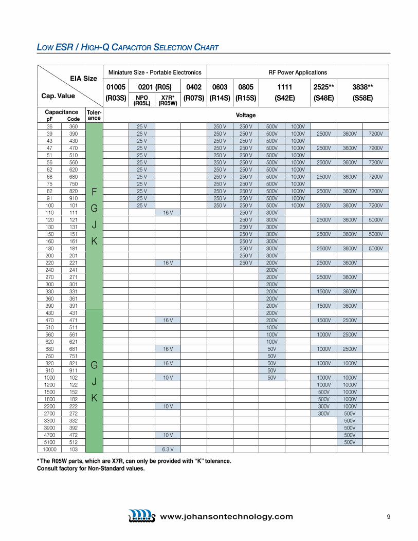
(R05W)Capacitance Toler-
ance VoltagepF Code36 360
F
G
J
K
25 V 250 V 250 V 500V 1000V39 390 25 V 250 V 250 V 500V 1000V 2500V 3600V 7200V43 430 25 V 250 V 250 V 500V 1000V47 470 25 V 250 V 250 V 500V 1000V 2500V 3600V 7200V51 510 25 V 250 V 250 V 500V 1000V56 560 25 V 250 V 250 V 500V 1000V 2500V 3600V 7200V62 620 25 V 250 V 250 V 500V 1000V68 680 25 V 250 V 250 V 500V 1000V 2500V 3600V 7200V75 750 25 V 250 V 250 V 500V 1000V82 820 25 V 250 V 250 V 500V 1000V 2500V 3600V 7200V91 910 25 V 250 V 250 V 500V 1000V100 101 25 V 250 V 250 V 500V 1000V 2500V 3600V 7200V110 111 16 V 250 V 300V120 121 250 V 300V 2500V 3600V 5000V130 131 250 V 300V150 151 250 V 300V 2500V 3600V 5000V160 161 250 V 300V180 181 250 V 300V 2500V 3600V 5000V200 201 250 V 300V220 221 16 V 250 V 200V 2500V 3600V240 241 200V270 271 200V 2500V 3600V300 301 200V330 331 200V 1500V 3600V360 361 200V390 391 200V 1500V 3600V430 431
G
J
K
200V470 471 16 V 200V 1500V 2500V510 511 100V560 561 100V 1000V 2500V620 621 100V680 681 16 V 50V 1000V 2500V750 751 50V820 821 16 V 50V 1000V 1000V910 911 50V1000 102 10 V 50V 1000V 1000V1200 122 1000V 1000V1500 152 500V 1000V1800 182 500V 1000V2200 222 10 V 300V 1000V2700 272 300V 500V3300 332 500V3900 392 500V4700 472 10 V 500V5100 512 500V
10000 103 6.3 V
low eSR / HigH-Q CapaCiToR SeleCTion CHaRT
EIA Size
Cap. Value
* The R05W parts, which are X7R, can only be provided with “K” tolerance.Consult factory for Non-Standard values.

10 www.johansontechnology.comwww.johansontechnology.com
meCHaniCal & environmenTal CHaraCTerisTiCs
SPECIFICATION TEST PARAMETERS SOLDERABILITY: Solder coverage ≥ 90% of metalized areas Preheat chip to 120°-150°C for 60 sec., dip terminals in rosin flux No termination degradation then dip in Sn62 solder @ 240°±5°C for 5±1 sec
RESISTANCE TO No mechanical damage Preheat device to 80°-100°C for 60 sec. SOLDERING HEAT: Capacitance change: ±2.5% or 0.25pF followed by 150°-180°C for 60 sec. Q>500 I.R. >10 G Ohms Dip in 260°±5°C solder for 10±1 sec. Breakdown voltage: 2.5 x WVDC Measure after 24±2 hour cooling period
TERMINAL Termination should not pull off. Linear pull force* exerted on axial leads soldered to each terminal. ADHESION: Ceramic should remain undamaged. *0402 ≥ 2.0lbs, 0603 ≥ 2.0lbs (min.)
PCB DEFLECTION: No mechanical damage. Glass epoxy PCB: 0.5 mm deflection Capacitance change: 2% or 0.5pF Max
LIFE TEST: No mechanical damage Applied voltage: 200% rated voltage, 50 mA max. Capacitance change: ±3.0% or 0.3 pF Temperature: 125°±3°C Q>500 I.R. >1 G Ohms Test time: 1000+48-0 hours Breakdown voltage: 2.5 x WVDC
THERMAL CYCLE: No mechanical damage. 5 cycles of: 30±3 minutes @ -55°+0/-3°C, Capacitance change: ±2.5% or 0.25pF 2-3 min. @ 25°C, 30±3 min. @ +125°+3/-0°C, Q>2000 I.R. >10 G Ohms 2-3 min. @ 25°C Breakdown voltage: 2.5 x WVDC Measure after 24±2 hour cooling period
HUMIDITY, No mechanical damage. Relative humidity: 90-95% STEADY STATE: Capacitance change: ±5.0% or 0.50pF max. Temperature: 40°±2°C Q>300 I.R. ≥ 1 G-Ohm Test time: 500 +12/-0 Hours Breakdown voltage: 2.5 x WVDC Measure after 24±2 hour cooling period
HUMIDITY, No mechanical damage. Applied voltage: 1.5 VDC, 50 mA max. LOW VOLTAGE: Capacitance change: ±5.0% or 0.50pF max. Relative humidity: 85±2% Temperature: 40°±2°C Q>300 I.R. = 1 G-Ohm min. Test time: 240 +12/-0 Hours Breakdown voltage: 2.5 x WVDC Measure after 24±2 hour cooling period
VIBRATION: No mechanical damage. Capacitance change: ±2.5% or 0.25pF Cycle performed for 2 hours in each of three perpendicular directions Q>1000 I.R. ≥ 10 G-Ohm Frequency range 10Hz to 55 Hz to 10 Hz traversed Breakdown voltage: 2.5 x WVDC in 1 minute. Harmonic motion amplitude: 1.5mm
DieleCTRiC CHaRaCTeRiSTiCS npo x7R
0 ± 30ppm /°C, -55 to 125°C
Q >1,000 @ 1 MHz, Typical 10,000
>10 GΩ @ 25°C,WVDC; 125°C IR is 10% of 25°C rating
2.5 X WVDC Min., 25°C, 50 mA max
1MHz ±50kHz, 1.0±0.2 VRMS, 25°C
Size 01005: 0.2 - 10 pFSize 0201: 0.2 - 100 pFSize 0402: 0.2 - 33 pFSize 0603: 0.2 - 430 pFSize 0805: 0.3 - 220 pFSize 1111: 0.2 - 1000 pFSize 2525: 1.0 - 2700 pFSize 3838: 1.0 - 5100 pF
± 15%, -55 to 125°C
16VDC DF≤ 3.5% @ 1 KHz, 25°C 10VDC DF≤ 5.0% @ 1 KHz, 25°C
>500 ΩF* or 10 GΩ* @ 25°C,WVDC; 125°C IR is 10% of 25°C rating * whichever is less
2.5 X WVDC Min., 25°C, 50 mA max
1KHz ±50Hz, 1.0±0.2 VRMS, 25°C
100 - 10,000 pF
TEMPERATURE COEFFICIENT:
QUALITY FACTOR / DF:
INSULATION RESISTANCE:
DIELECTRIC STRENGTH:
TEST PARAMETERS:
AVAILABLE CAPACITANCE:
11www.johansontechnology.comwww.johansontechnology.com
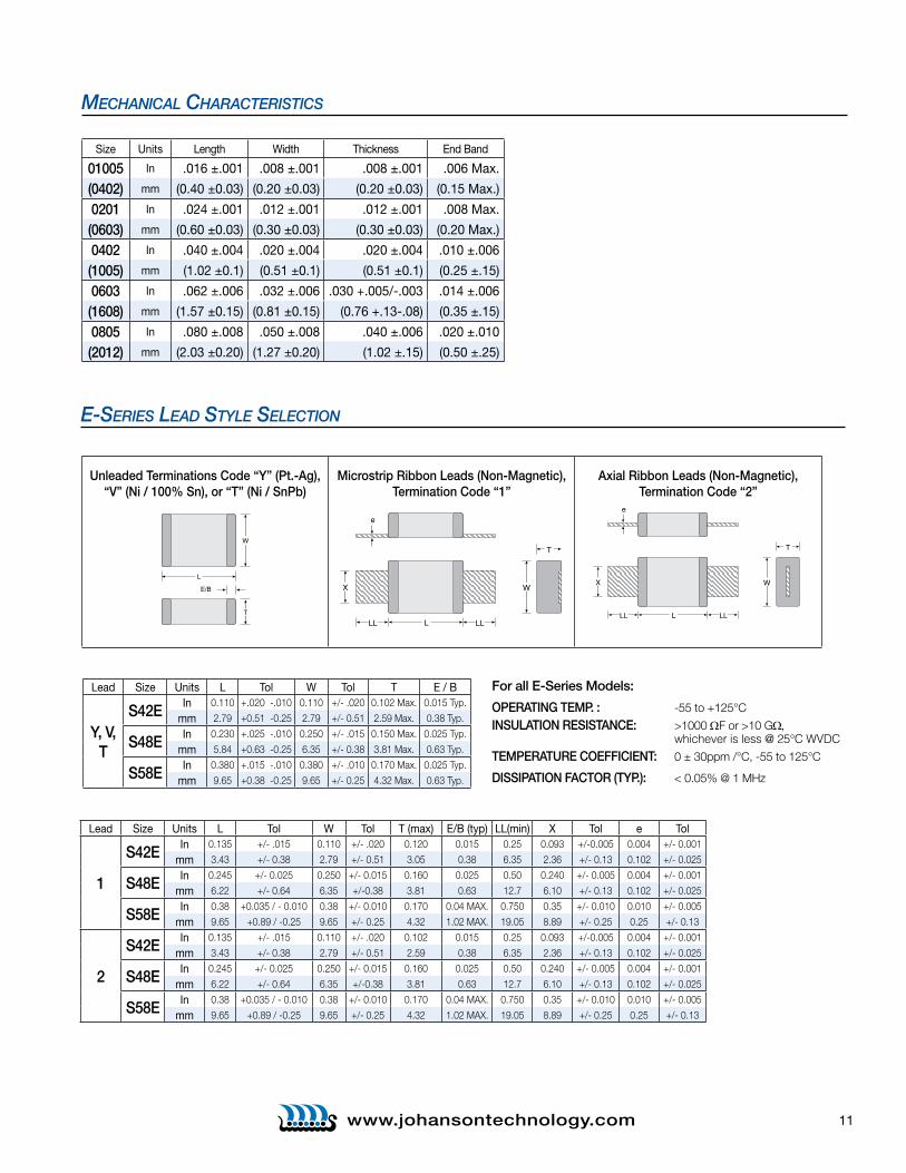
Lead Size Units L Tol W Tol T E / B
Y, V, T
S42E In 0.110 +.020 -.010 0.110 +/- .020 0.102 Max. 0.015 Typ.
mm 2.79 +0.51 -0.25 2.79 +/- 0.51 2.59 Max. 0.38 Typ.
S48E In 0.230 +.025 -.010 0.250 +/- .015 0.150 Max. 0.025 Typ.
mm 5.84 +0.63 -0.25 6.35 +/- 0.38 3.81 Max. 0.63 Typ.
S58E In 0.380 +.015 -.010 0.380 +/- .010 0.170 Max. 0.025 Typ.
mm 9.65 +0.38 -0.25 9.65 +/- 0.25 4.32 Max. 0.63 Typ.
e-SeRieS leaD STyle SeleCTion
Unleaded Terminations Code “Y” (Pt.-Ag), “V” (Ni / 100% Sn), or “T” (Ni / SnPb)
Microstrip Ribbon Leads (Non-Magnetic), Termination Code “1”
Axial Ribbon Leads (Non-Magnetic), Termination Code “2”
L
E/B
T
W
L
e
T
W
LLLL
X
Lead Size Units L Tol W Tol T (max) E/B (typ) LL(min) X Tol e Tol
1
S42E In 0.135 +/- .015 0.110 +/- .020 0.120 0.015 0.25 0.093 +/-0.005 0.004 +/- 0.001
mm 3.43 +/- 0.38 2.79 +/- 0.51 3.05 0.38 6.35 2.36 +/- 0.13 0.102 +/- 0.025
S48E In 0.245 +/- 0.025 0.250 +/- 0.015 0.160 0.025 0.50 0.240 +/- 0.005 0.004 +/- 0.001
mm 6.22 +/- 0.64 6.35 +/-0.38 3.81 0.63 12.7 6.10 +/- 0.13 0.102 +/- 0.025
S58E In 0.38 +0.035 / - 0.010 0.38 +/- 0.010 0.170 0.04 MAX. 0.750 0.35 +/- 0.010 0.010 +/- 0.005
mm 9.65 +0.89 / -0.25 9.65 +/- 0.25 4.32 1.02 MAX. 19.05 8.89 +/- 0.25 0.25 +/- 0.13
2
S42E In 0.135 +/- .015 0.110 +/- .020 0.102 0.015 0.25 0.093 +/-0.005 0.004 +/- 0.001
mm 3.43 +/- 0.38 2.79 +/- 0.51 2.59 0.38 6.35 2.36 +/- 0.13 0.102 +/- 0.025
S48E In 0.245 +/- 0.025 0.250 +/- 0.015 0.160 0.025 0.50 0.240 +/- 0.005 0.004 +/- 0.001
mm 6.22 +/- 0.64 6.35 +/-0.38 3.81 0.63 12.7 6.10 +/- 0.13 0.102 +/- 0.025
S58E In 0.38 +0.035 / - 0.010 0.38 +/- 0.010 0.170 0.04 MAX. 0.750 0.35 +/- 0.010 0.010 +/- 0.005
mm 9.65 +0.89 / -0.25 9.65 +/- 0.25 4.32 1.02 MAX. 19.05 8.89 +/- 0.25 0.25 +/- 0.13
L
e
T
W
LLLL
X
For all E-Series Models:
OPERATING TEMP. : -55 to +125°C INSULATION RESISTANCE: >1000 ΩF or >10 GΩ, whichever is less @ 25°C WVDC TEMPERATURE COEFFICIENT: 0 ± 30ppm /°C, -55 to 125°C
DISSIPATION FACTOR (TYP.): < 0.05% @ 1 MHz
Size Units Length Width Thickness End Band
01005 In .016 ± .001 .008 ± .001 .008 ± .001 .006 Max .
(0402) mm (0 .40 ±0 .03) (0 .20 ±0 .03) (0 .20 ±0 .03) (0 .15 Max .)
0201 In .024 ± .001 .012 ± .001 .012 ± .001 .008 Max .
(0603) mm (0 .60 ±0 .03) (0 .30 ±0 .03) (0 .30 ±0 .03) (0 .20 Max .)
0402 In .040 ± .004 .020 ± .004 .020 ± .004 .010 ± .006
(1005) mm (1 .02 ±0 .1) (0 .51 ±0 .1) (0 .51 ±0 .1) (0 .25 ± .15)
0603 In .062 ± .006 .032 ± .006 .030 + .005/- .003 .014 ± .006
(1608) mm (1 .57 ±0 .15) (0 .81 ±0 .15) (0 .76 + .13- .08) (0 .35 ± .15)
0805 In .080 ± .008 .050 ± .008 .040 ± .006 .020 ± .010
(2012) mm (2 .03 ±0 .20) (1 .27 ±0 .20) (1 .02 ± .15) (0 .50 ± .25)
meCHaniCal CHaraCTerisTiCs
12 www.johansontechnology.com
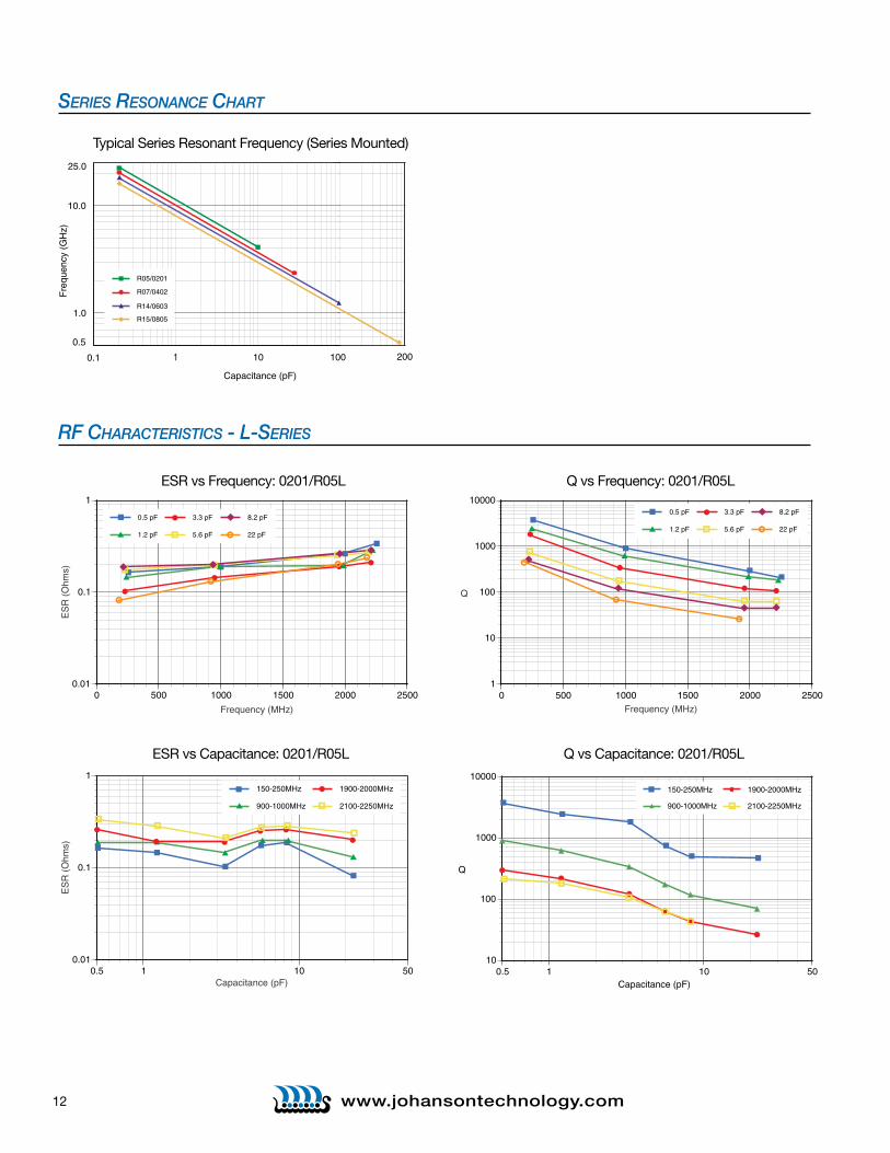
0.01
0.1
1
0 500 1000 1500 2000 2500
ES
R (
Ohm
s)
Frequency (MHz)
0.5 pF
1.2 pF
3.3 pF
5.6 pF
8.2 pF
22 pF
ESR vs Frequency: 0201/R05L
1
10
100
1000
10000
0 500 1000 1500 2000 2500
Q
Frequency (MHz)
0.5 pF
1.2 pF
3.3 pF
5.6 pF
8.2 pF
22 pF
Q vs Frequency: 0201/R05L
0.01
0.1
1
0.5 1 10 50
ES
R (
Ohm
s)
Capacitance (pF)
150-250MHz
900-1000MHz
1900-2000MHz
2100-2250MHz
ESR vs Capacitance: 0201/R05L
10
100
1000
10000
0.5 1 10 50
Q
Capacitance (pF)
150-250MHz
900-1000MHz
1900-2000MHz
2100-2250MHz
Q vs Capacitance: 0201/R05L
RF CHaRaCTeRiSTiCS - l-SeRieS
series resonanCe CHarT
0.5
1.0
10.0
25.0
Fre
quen
cy (
GH
z)
Capacitance (pF)
0.1 1 10 100 200
R05/0201
R07/0402
R14/0603
R15/0805
Typical Series Resonant Frequency (Series Mounted)
13www.johansontechnology.com
Measurements performed on a Boonton 34A Resonant Coaxial Line and represent typical capacitor performance.
H
0.01
0.1
1
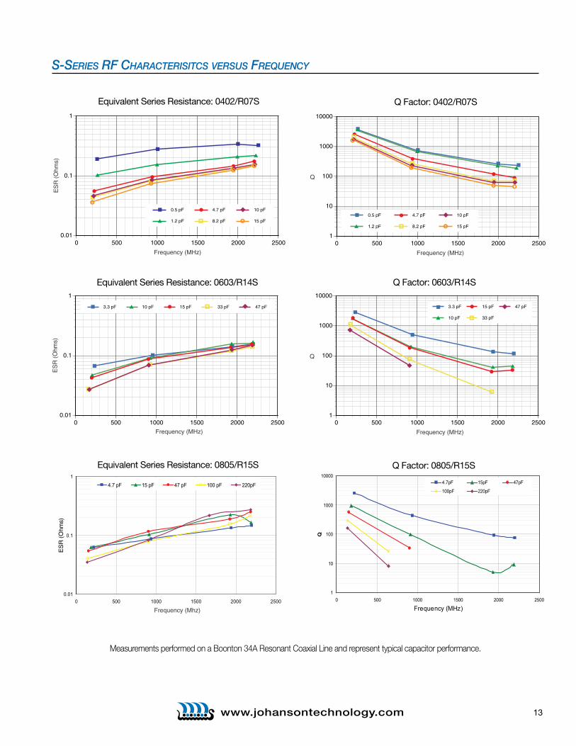
0 500 1000 1500 2000 2500
ES
R (
Ohm
s)
Frequency (MHz)
3.3 pF 10 pF 15 pF 33 pF 47 pF
Equivalent Series Resistance: 0603/R14S
1
10
100
1000
10000
0 500 1000 1500 2000 2500
Q
Frequency (MHz)
3.3 pF
10 pF
15 pF
33 pF
47 pF
Q Factor: 0603/R14S
0.01
0.1
1
0 500 1000 1500 2000 2500
ES
R (
Ohm
s)
Frequency (MHz)
0.5 pF
1.2 pF
4.7 pF
8.2 pF
10 pF
15 pF
Equivalent Series Resistance: 0402/R07S
1
10
100
1000
10000
0 500 1000 1500 2000 2500
Q
Frequency (MHz)
0.5 pF
1.2 pF
4.7 pF
8.2 pF
10 pF
15 pF
Q Factor: 0402/R07S
S-SeRieS RF CHaRaCTeRiSiTCS veRSuS FReQuenCy
1
10
100
1000
10000
0 500 1000 1500 2000 2500
Q
4.7pF 15pF 47pF
100pF 220pF
Frequency (MHz)
Q Factor: 0805/R15S
0.01
0.1
1
0 500 1000 1500 2000 2500
ES
R (
Ohm
s)
4.7 pF 15 pF 47 pF 100 pF 220pF
Frequency (Mhz)
Equivalent Series Resistance: 0805/R15S

14 www.johansontechnology.com
S-SeRieS RF CHaRaCTeRiSiTCS veRSuS CapaCiTanCe
0.01
0.1
1
1 10 50
ES
R (
Ohm
s)
Capacitance (pF)
150-250MHz
900-1000MHz
1900-2000MHz 2100-2250MHz
Equivalent Series Resistance: 0603/R14S
1
10
100
1000
10000
1 10 50
Q
Capacitance (pF)
150-250MHz
900-1000MHz
1900-2000MHz
2100-2250MHz
Q Factor: 0603/R14S
0.01
0.1
1
0.5 1 10 20
ES
R (
Ohm
s)
Capacitance (pF)
150-250MHz
900-1000MHz
1900-2000MHz
2100-2250MHz
Equivalent Series Resistance: 0402/R07S
1
10
100
1000
10000
0.5 1 10 20
Q
Capacitance (pF)
150-250MHz
900-1000MHz
1900-2000MHz 2100-2250MHz
Q Factor: 0402/R07S
0.01
0.1
1
1 10 100 1000
150-250MHz 900-1000MHz 1900-2000MHz 2100-2250MHz
ESR
(Ohm
s)
Capacitance (pF)
Equivalent Series Resistance: 0805/R15S
1
10
100
1000
10000
1 10 100 1000
150-250MHz 900-1000MHz1900-2000MHz 2100-2250MHz
ESR
(Ohm
s)
Capacitance (pF)
Q Factor: 0805/R15S
Measurements performed on a Boonton 34A Resonant Coaxial Line and represent typical capacitor performance.

15www.johansontechnology.com
As measured on a 8720C VNA, using a Shunt-Through fixture, and using the S11 magnitude dip to determine the SRF
SRF (Shunt Mount), S42E, Typical
0.1
1
10
1 1 0 100 1000
Capacitance (pF)
Freq
uenc
y (G
Hz)
JTI S42E SRF
100
1000
10000
100000
1 1 0 100 1000
Q
10
S42E Q vs. Capacitance, Typical
Q vs C @ 64 MHz
Q vs C @ 128 MHz
Capacitance (pF)
As measured on a 4287A LCR meter, using a 16092A fixture
0.010
0.100
1 10 100 1000
S42E ESR vs. Capacitance, Typical
ES
R (
ohm
s)
ESR vs. C @ 64 MHz
ESR vs. C @ 128 MHz
Capacitance (pF)
As measured on a 4287A LCR meter, using a 16092A fixture
0.1
1
10
100
1 10 100 1000 10000
Capacitance (pF)
Current Rating vs. Capacitance, S42E, Typical (Preliminary)
Cu
rre
nt
Ra
tin
g (
am
ps)
30 MHz
64 MHz
128 MHz
Solid traces show voltage limited current (Vrms)Dotted traces show power dissipation limited current (Based on 3 Watts Power Dissipation, and 125 degrees C case temp.)
JTi S42e gRapHiCal DaTa
16 www.johansontechnology.comwww.johansontechnology.com
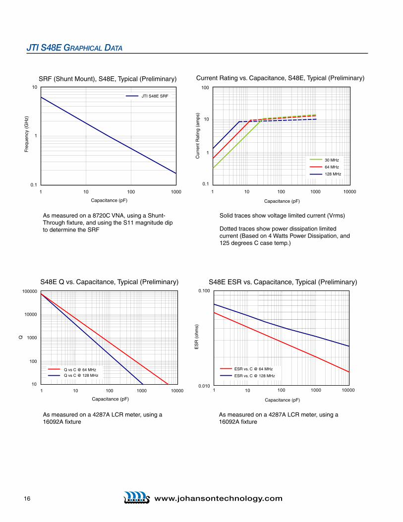
JTi S48e gRapHiCal DaTa
As measured on a 8720C VNA, using a Shunt-Through fixture, and using the S11 magnitude dip to determine the SRF
0.1
1
10
1 1 0 100 1000
SRF (Shunt Mount), S48E, Typical (Preliminary)
Capacitance (pF)
JTI S48E SRF
Freq
uenc
y (G
Hz)
0.1
1
10
100
1 10 100 1000 10000
Current Rating vs. Capacitance, S48E, Typical (Preliminary)
Capacitance (pF)C
urre
nt R
atin
g (a
mps
)
30 MHz
64 MHz
128 MHz
As measured on a 4287A LCR meter, using a 16092A fixture
As measured on a 4287A LCR meter, using a 16092A fixture
Solid traces show voltage limited current (Vrms)
Dotted traces show power dissipation limited current (Based on 4 Watts Power Dissipation, and 125 degrees C case temp.)
0.010
0.100
1 10 100 1000 10000
S48E ESR vs. Capacitance, Typical (Preliminary)
ES
R (
ohm
s)
ESR vs. C @ 64 MHz
ESR vs. C @ 128 MHz
Capacitance (pF)
100
1000
10000
100000
1000 1 10 100 10000
Q
10
S48E Q vs. Capacitance, Typical (Preliminary)
Capacitance (pF)
Q vs C @ 64 MHzQ vs C @ 128 MHz
http://www.murata.com/
Data Sheet
!Note:1. This datasheet is downloaded from the website of Murata Manufacturing co., ltd. Therefore, it’s specifications are subject to change or our
products in it may be discontinued without advance notice. Please check with our sales representatives or product engineers before ordering.
2. This datasheet has only typical specifications because there is no space for detailed specifications. Therefore, please approve our product specifications or transact the approval sheet for product specifications before ordering.
2008.3.6
Capacitors > Monolithic Ceramic Capacitors
o This data sheet is applied for CHIP MONOLITHIC CERAMIC CAPACITOR used for Automotive (For Power-train, Safety equipments) Electronics equipment for your design.
<Notice>o Solderability of Tin plating termination chip might be deteriorated when low temperature soldering profile where peak solder temperature is below the Tin
melting point is used. Please confirm the solderability of Tin plating termination chip before use.
• The RoHS compliance means that we judge from EU Directive 2002/95/EC the products do not contain lead, cadmium, mercury, hexavalent chromium, PBB and PBDE, except exemptions stated in EU Directive 2002/95/EC annex and impurities existing in natural world.
• This statement does not insure the compliance of any of the listed parts with any laws or legal imperatives developed by any EU members individually with regards to the RoHS Directive.
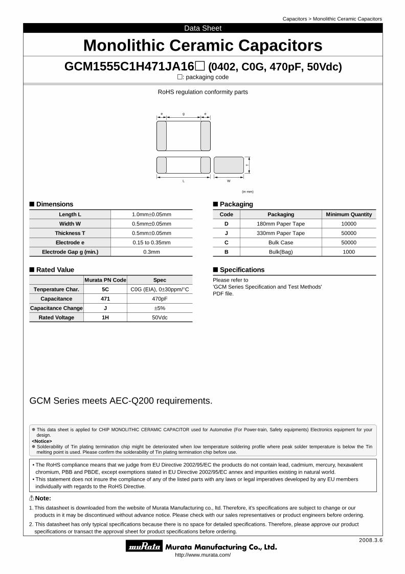
Monolithic Ceramic CapacitorsGCM1555C1H471JA16p (0402, C0G, 470pF, 50Vdc)
p: packaging code
L
T
W
(in mm)
e eg
RoHS regulation conformity parts
GCM Series meets AEC-Q200 requirements.
DimensionsLength L 1.0mm±0.05mm
Width W 0.5mm±0.05mm
Thickness T 0.5mm±0.05mm
Electrode e 0.15 to 0.35mm
Electrode Gap g (min.) 0.3mm
Rated ValueMurata PN Code Spec
Tenperature Char. 5C C0G (EIA), 0±30ppm/°C
Capacitance 471 470pF
Capacitance Change J ±5%
Rated Voltage 1H 50Vdc
PackagingCode Packaging Minimum Quantity
D 180mm Paper Tape 10000
J 330mm Paper Tape 50000
C Bulk Case 50000
B Bulk(Bag) 1000
SpecificationsPlease refer to 'GCM Series Specification and Test Methods'PDF file.

o Part Numbering
(Part Number)
w
qProduct ID
wSeries
Chip Monolithic Ceramic Capacitors
GCJ
M
Soft Termination Type Power-train, Safety Equipment
Power-train, Safety Equipment
Product ID Code Series
GC
q
M
e
18
r
8
t
R7
y
1H
u
102
i
K
o
A37
eDimension (LgW)
!0
D
Code
0.6g0.3mm
1.0g0.5mm
1.6g0.8mm
2.0g1.25mm
3.2g1.6mm
3.2g2.5mm
4.5g3.2mm
5.7g5.0mm
Dimension (LgW)
0201
0402
0603
0805
1206
1210
1812
2220
EIA
03
15
18
21
31
32
43
55
B
C
D
E
M
N
Q
R
X
1.25mm
1.6mm
2.0mm
2.5mm
1.15mm
1.35mm
1.5mm
1.8mm
Depends on individual standards.
A 1.0mm
rDimension (T)
Code
3
5
6
8
9
0.3mm
0.5mm
0.6mm
0.8mm
0.85mm
Dimension (T)
Continued on the following page.
uCapacitance
Expressed by three-digit alphanumerics. The unit is pico-farad (pF). The first and second figures are significant digits, and the third figure expresses the number of zeros which follow the two numbers.If there is a decimal point, it is expressed by the capital letter "R". In this case, all figures are significant digits.
R50
1R0
100
103
Ex.)
0.5pF
1.0pF
10pF
10000pF
Code Capacitance
yRated Voltage
0J
1A
1C
1E
YA
1H
2A
2E
2J
DC6.3V
DC10V
DC16V
DC25V
DC35V
DC50V
DC100V
DC250V
DC630V
Code Rated Voltage
-55 to 125°C
-55 to 125°C
±22%
±15%
X7S
X7R
C7
R7
-55 to 125°C
-55 to 125°C
tTemperature Characteristics
Code
Temperature Characteristic Codes Temperature Characteristics
25 to 125°C25°C
TemperatureRange
ReferenceTemperature
0±30ppm/°C
Capacitance Change or Temperature Coefficient
C0G EIA
25°C
25°C
EIA
EIA
25 to 125°C -750±120ppm/°CU2J7U -55 to 125°C25°CEIA
Public STD Code
5C -55 to 125°C
Operating Temperature
Range
Murata Code
Capacitance Change from 25°C (%)
–55°C –30°C –10°C
Max. Min. Max. Min. Max. Min.
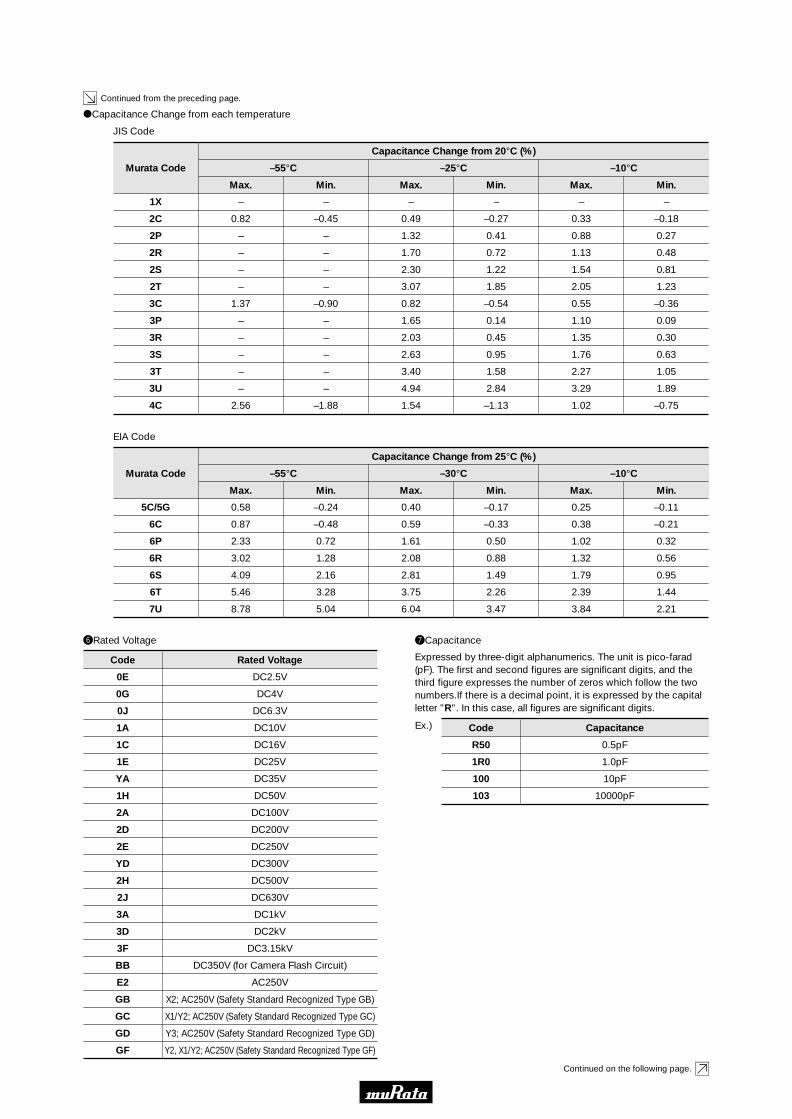
5C 0.58 –0.24 0.40 –0.17 0.25 –0.11
7U 8.78 5.04 6.04 3.47 3.84 2.21
oCapacitance Change from each temperature
Continued from the preceding page.
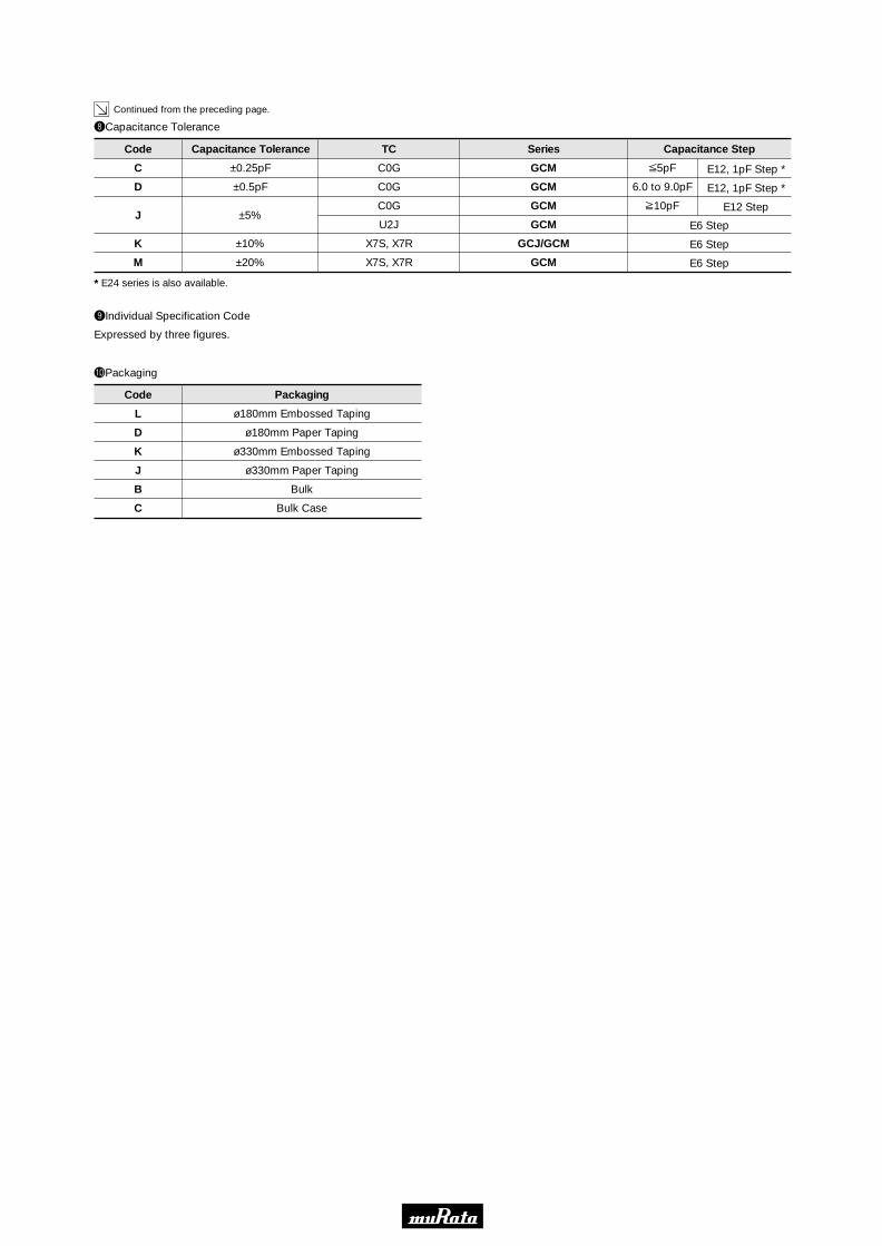
!0Packaging
Code
L
D
K
J
B
C
ø180mm Embossed Taping
ø180mm Paper Taping
ø330mm Embossed Taping
ø330mm Paper Taping
Bulk
Bulk Case
Packaging
iCapacitance Tolerance
Code
C
D
J
K
M
GCM
GCM
GCM
GCM
GCJ/GCM
GCM
Series
C0G
C0G
C0G
U2J
X7S, X7R
X7S, X7R
TC
±0.25pF
±0.5pF
±5%
±10%
±20%
Capacitance Tolerance
V5pF
6.0 to 9.0pF
U10pF
E12, 1pF Step *
E12, 1pF Step *
E12 Step
Capacitance Step
E6 Step
E6 Step
E6 Step
* E24 series is also available.
Expressed by three figures.
oIndividual Specification Code
http://www.murata.com/
Data Sheet
!Note:1. This datasheet is downloaded from the website of Murata Manufacturing co., ltd. Therefore, it’s specifications are subject to change or our
products in it may be discontinued without advance notice. Please check with our sales representatives or product engineers before ordering.
2. This datasheet has only typical specifications because there is no space for detailed specifications. Therefore, please approve our product specifications or transact the approval sheet for product specifications before ordering.
2008.3.6
Capacitors > Monolithic Ceramic Capacitors
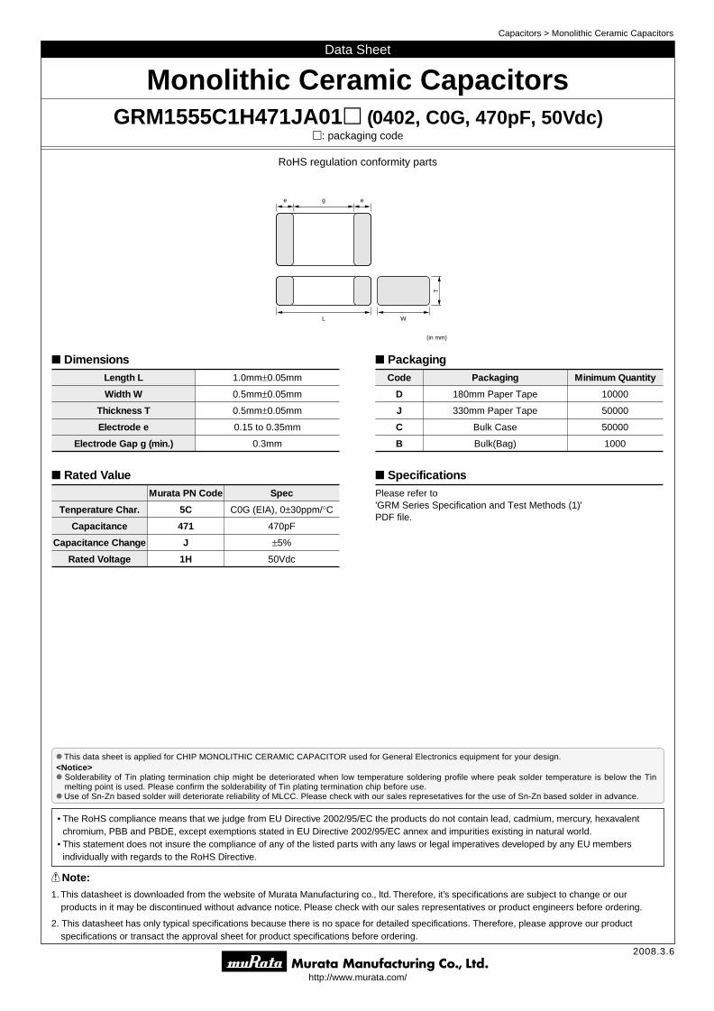
o This data sheet is applied for CHIP MONOLITHIC CERAMIC CAPACITOR used for General Electronics equipment for your design.<Notice>o Solderability of Tin plating termination chip might be deteriorated when low temperature soldering profile where peak solder temperature is below the Tin
melting point is used. Please confirm the solderability of Tin plating termination chip before use.o Use of Sn-Zn based solder will deteriorate reliability of MLCC. Please check with our sales represetatives for the use of Sn-Zn based solder in advance.
• The RoHS compliance means that we judge from EU Directive 2002/95/EC the products do not contain lead, cadmium, mercury, hexavalent chromium, PBB and PBDE, except exemptions stated in EU Directive 2002/95/EC annex and impurities existing in natural world.
• This statement does not insure the compliance of any of the listed parts with any laws or legal imperatives developed by any EU members individually with regards to the RoHS Directive.
Monolithic Ceramic CapacitorsGRM1555C1H471JA01p (0402, C0G, 470pF, 50Vdc)
p: packaging code
L
T
W
(in mm)
e eg
RoHS regulation conformity parts
DimensionsLength L 1.0mm±0.05mm
Width W 0.5mm±0.05mm
Thickness T 0.5mm±0.05mm
Electrode e 0.15 to 0.35mm
Electrode Gap g (min.) 0.3mm
Rated ValueMurata PN Code Spec
Tenperature Char. 5C C0G (EIA), 0±30ppm/°C
Capacitance 471 470pF
Capacitance Change J ±5%
Rated Voltage 1H 50Vdc
PackagingCode Packaging Minimum Quantity
D 180mm Paper Tape 10000
J 330mm Paper Tape 50000
C Bulk Case 50000
B Bulk(Bag) 1000
SpecificationsPlease refer to 'GRM Series Specification and Test Methods (1)'PDF file.

(Part Number)
w
qProduct ID
wSeries
Chip Monolithic Ceramic Capacitors
GR
ER
GQ
GM
GN
LL
GJ
GA
J
M
4
7
B
M
A
D
M
L
A
M
M
2
3
Soft Termination Type
Tin Plated Layer
Only for Information Devices / Tip & Ring
Only for Camera Flash Circuit
High Frequency Type
High Frequency forFlow/Reflow Soldering
Monolithic Microchip
for Bonding
Capacitor Array
Low ESL Wide Width Type
Eight-termination Low ESL Type
Ten-termination Low ESL Type
High Frequency Low Loss Type
for AC250V (r.m.s.)
Safety Standard Recognized Type
Product ID Code Series
GR
q
M
e
18
r
8
t
B1
y
1H
u
102
i
K
o
A01
With the array type GNM series, "Dimension(T)" indicates the number of elements.
eDimension (LgW)
!0
D
Code
0.4g0.2mm
0.6g0.3mm
0.5g0.5mm
0.8g0.8mm
0.38g0.38mm
0.9g0.6mm
1.25g1.0mm
1.0g0.5mm
1.6g0.8mm
1.37g1.0mm
2.0g1.25mm
2.8g2.8mm
3.2g1.6mm
3.2g2.5mm
4.5g2.0mm
4.5g3.2mm
5.7g2.8mm
5.7g5.0mm
Dimension (LgW)
01005
0201
0202
0303
015015
0302
0504
0402
0603
0504
0805
1111
1206
1210
1808
1812
2211
2220
EIA
02
03
05
08
0D
0M
11
15
18
1M
21
22
31
32
42
43
52
55
A
B
C
D
E
F
M
N
Q
R
S
X
1.0mm
1.25mm
1.6mm
2.0mm
2.5mm
3.2mm
1.15mm
1.35mm
1.5mm
1.8mm
2.8mm
Depends on individual standards.
rDimension (T)
Code
2
2
3
4
5
6
7
8
9
0.2mm
2-elements (Array Type)
0.3mm
4-elements (Array Type)
0.5mm
0.6mm
0.7mm
0.8mm
0.85mm
Dimension (T)
Continued on the following page.
o Part Numberingo Part Numbering
Continued from the preceding page.
Continued on the following page.
25 to 85°C
25 to 85°C
25 to 85°C
25 to 125°C *6
-25 to 85°C
-25 to 85°C
-55 to 125°C
-55 to 105°C
-220±60ppm/°C
-330±60ppm/°C
-470±60ppm/°C
-750±120ppm/°C
±10%
±10%
±22%
±22%
R2H *1
S2H *1
T2H *1
U2J *1
B *2
B
X7S
X6S
6R
6S
6T
7U
B1
B3
C7
C8
-55 to 125°C
-55 to 125°C
-55 to 125°C
-55 to 125°C
-25 to 85°C
-25 to 85°C
-55 to 125°C
-55 to 105°C
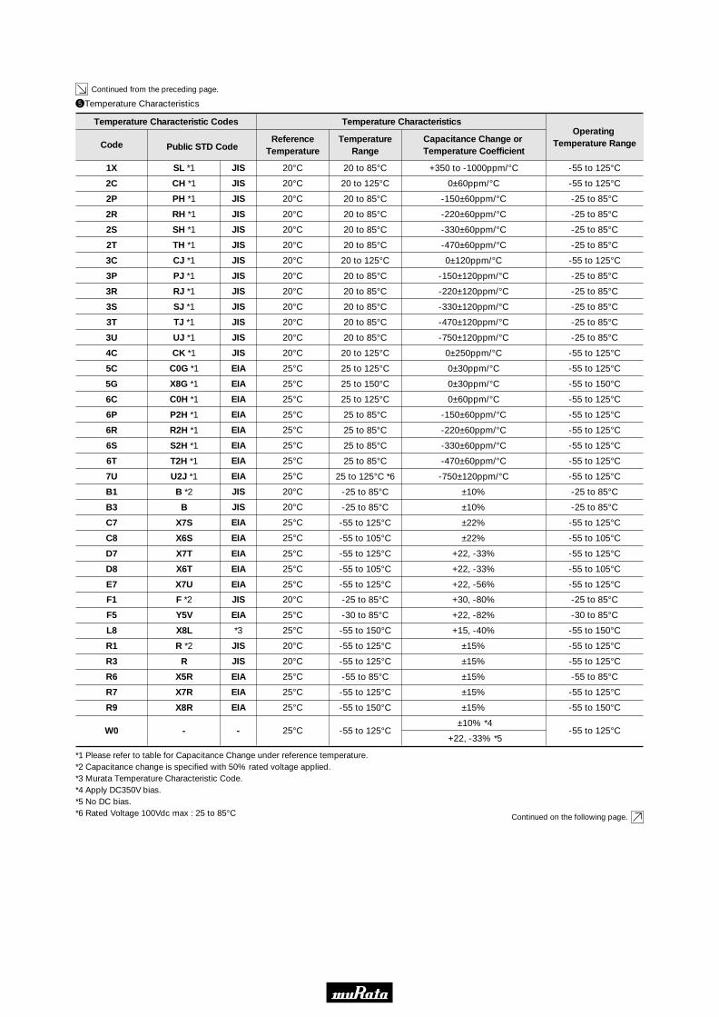
tTemperature Characteristics
Code
Temperature Characteristic Codes Temperature Characteristics
20 to 85°C
20 to 125°C
20 to 85°C
20 to 85°C
20 to 85°C
20 to 85°C
20 to 125°C
20 to 85°C
20 to 85°C
20 to 85°C
20 to 85°C
20 to 85°C
20 to 125°C
25 to 125°C
25 to 150°C
25 to 125°C
25 to 85°C
20°C
20°C
20°C
20°C
20°C
20°C
20°C
20°C
20°C
20°C
20°C
20°C
20°C
25°C
25°C
25°C
25°C
TemperatureRange
ReferenceTemperature
+350 to -1000ppm/°C
0±60ppm/°C
-150±60ppm/°C
-220±60ppm/°C
-330±60ppm/°C
-470±60ppm/°C
0±120ppm/°C
-150±120ppm/°C
-220±120ppm/°C
-330±120ppm/°C
-470±120ppm/°C
-750±120ppm/°C
0±250ppm/°C
0±30ppm/°C
0±30ppm/°C
0±60ppm/°C
-150±60ppm/°C
Capacitance Change or Temperature Coefficient
SL *1
CH *1
PH *1
RH *1
SH *1
TH *1
CJ *1
PJ *1
RJ *1
SJ *1
TJ *1
UJ *1
CK *1
C0G *1
X8G *1
C0H *1
P2H *1
JIS
JIS
JIS
JIS
JIS
JIS
JIS
JIS
JIS
JIS
JIS
JIS
JIS
EIA
EIA
EIA
EIA
25°C
25°C
25°C
25°C
20°C
20°C
25°C
25°C
EIA
EIA
EIA
EIA
JIS
JIS
EIA
EIA
-25 to 85°C
-30 to 85°C
-55 to 150°C
-55 to 125°C
-55 to 125°C
-55 to 85°C
-55 to 125°C
-55 to 150°C
-55 to 125°C
+30, -80%
+22, -82%
+15, -40%
±15%
±15%
±15%
±15%
±15%
±10% *4
+22, -33% *5
F *2
Y5V
X8L
R *2
R
X5R
X7R
X8R
-
F1
F5
L8
R1
R3
R6
R7
R9
W0
-25 to 85°C
-30 to 85°C
-55 to 150°C
-55 to 125°C
-55 to 125°C
-55 to 85°C
-55 to 125°C
-55 to 150°C
-55 to 125°C
20°C
25°C
25°C
20°C
20°C
25°C
25°C
25°C
25°C
JIS
EIA
*3
JIS
JIS
EIA
EIA
EIA
-
-55 to 125°C +22, -33%X7TD7 -55 to 125°C25°CEIA
-55 to 105°C +22, -33%X6TD8 -55 to 105°C25°CEIA
-55 to 125°C +22, -56%X7UE7 -55 to 125°C25°CEIA
Public STD Code
1X
2C
2P
2R
2S
2T
3C
3P
3R
3S
3T
3U
4C
5C
5G
6C
6P
-55 to 125°C
-55 to 125°C
-25 to 85°C
-25 to 85°C
-25 to 85°C
-25 to 85°C
-55 to 125°C
-25 to 85°C
-25 to 85°C
-25 to 85°C
-25 to 85°C
-25 to 85°C
-55 to 125°C
-55 to 125°C
-55 to 150°C
-55 to 125°C
-55 to 125°C
Operating Temperature Range
*1 Please refer to table for Capacitance Change under reference temperature. *2 Capacitance change is specified with 50% rated voltage applied.*3 Murata Temperature Characteristic Code.*4 Apply DC350V bias.*5 No DC bias.*6 Rated Voltage 100Vdc max : 25 to 85°C
Continued from the preceding page.
Murata Code
Capacitance Change from 25°C (%)
–55°C –30°C –10°C
Max. Min. Max. Min. Max. Min.
5C/5G 0.58 –0.24 0.40 –0.17 0.25 –0.11
6C 0.87 –0.48 0.59 –0.33 0.38 –0.21
6P 2.33 0.72 1.61 0.50 1.02 0.32
6R 3.02 1.28 2.08 0.88 1.32 0.56
6S 4.09 2.16 2.81 1.49 1.79 0.95
6T 5.46 3.28 3.75 2.26 2.39 1.44
7U 8.78 5.04 6.04 3.47 3.84 2.21
EIA Code
4C 2.56 –1.88 1.54 –1.13 1.02 –0.75
3P – – 1.65 0.14 1.10 0.09
3R – – 2.03 0.45 1.35 0.30
3S – – 2.63 0.95 1.76 0.63
3T – – 3.40 1.58 2.27 1.05
3U – – 4.94 2.84 3.29 1.89
3C 1.37 –0.90 0.82 –0.54 0.55 –0.36
Murata Code
Capacitance Change from 20°C (%)
–55°C –25°C –10°C
Max. Min. Max. Min. Max. Min.
2C 0.82 –0.45 0.49 –0.27 0.33 –0.18
2P – – 1.32 0.41 0.88 0.27
2R – – 1.70 0.72 1.13 0.48
2S – – 2.30 1.22 1.54 0.81
2T – – 3.07 1.85 2.05 1.23
1X – – – – – –
oCapacitance Change from each temperature
JIS Code
uCapacitance
Expressed by three-digit alphanumerics. The unit is pico-farad (pF). The first and second figures are significant digits, and the third figure expresses the number of zeros which follow the two numbers.If there is a decimal point, it is expressed by the capital letter "R". In this case, all figures are significant digits.
R50
1R0
100
103
Ex.)
0.5pF
1.0pF
10pF
10000pF
Code Capacitance
yRated Voltage
0E
0G
0J
1A
1C
1E
YA
1H
2A
2D
2E
YD
2H
2J
3A
3D
3F
BB
E2
GB
GC
GD
GF
DC2.5V
DC4V
DC6.3V
DC10V
DC16V
DC25V
DC35V
DC50V
DC100V
DC200V
DC250V
DC300V
DC500V
DC630V
DC1kV
DC2kV
DC3.15kV
DC350V (for Camera Flash Circuit)
AC250V
X2; AC250V (Safety Standard Recognized Type GB)
X1/Y2; AC250V (Safety Standard Recognized Type GC)
Y3; AC250V (Safety Standard Recognized Type GD)
Y2, X1/Y2; AC250V (Safety Standard Recognized Type GF)
Code Rated Voltage
Continued on the following page.

Continued from the preceding page.
Expressed by three figures.
oIndividual Specification Code
iCapacitance Tolerance
Code
W GRM/GJM
Series
C∆
TC
±0.05pF
Capacitance Tolerance
V9.9pF 0.1pF
B
GRM/GJM
GQM
ERB
C∆±0.1pF
V9.9pF
V1pF
1.1 to 9.9pF
V9.9pF
0.1pF
0.1pF
1pF Step and E24 Series
1pF Step and E24 Series
C
GRM/GJM
GRM
ERB
GQM
C∆
except C∆
C∆
±0.25pF
V9.9pF
V5pF
V9.9pF
V1pF
1.1 to 9.9pF
0.1pF
* 1pF
1pF Step and E24 Series
0.1pF
1pF Step and E24 Series
D
GRM/GJM
GRM
ERB/GQM
C∆
except C∆
C∆
±0.5pF
5.1 to 9.9pF
5.1 to 9.9pF
5.1 to 9.9pF
0.1pF
* 1pF
1pF Step and E24 Series
GGJM
GQM/ERB
C∆
C∆±2%
U10pF
U10pF
E12 Series
E24 Series
JGRM/GA3
ERB/GQM/GJM
C∆–SL
C∆±5%
U10pF
U10pF
E12 Series
E24 Series
Capacitance Step
K
GRJ/GRM/GR7/GA3
GNM
GR4, GMD
B, R, X7R, X5R, ZLM
C0G
B, R, X7R, X5R, ZLM
±10%
E6 Series
E6 Series
E12 Series
M
GRM/GMA
GNM
GA2
LLL/LLA/LLM
B, R, X7R, X7S
X5R, X7R, X7S
X7R
X5R, X7R, X7S, X6S
±20%
E6 Series
E3 Series
E3 Series
E3 Series
Z GRMF, Y5V+80%, -20% E3 Series
R Depends on individual standards.
* E24 series is also available.
!0Packaging
Code
L
D
E
K
J
F
B
C
T
ø180mm Embossed Taping
ø180mm Paper Taping
ø180mm Paper Taping (LLL15)
ø330mm Embossed Taping
ø330mm Paper Taping
ø330mm Paper Taping (LLL15)
Bulk
Bulk Case
Bulk Tray
Packaging
Design and specifi cations are each subject to change without notice. Ask factory for the current technical specifi cations before purchase and/or use.Should a safety concern arise regarding this product, please be sure to contact us immediately.
Multilayer Ceramic Capacitors(High-Q Capacitors)
– EC39 –
Ceram
ic Capacitors
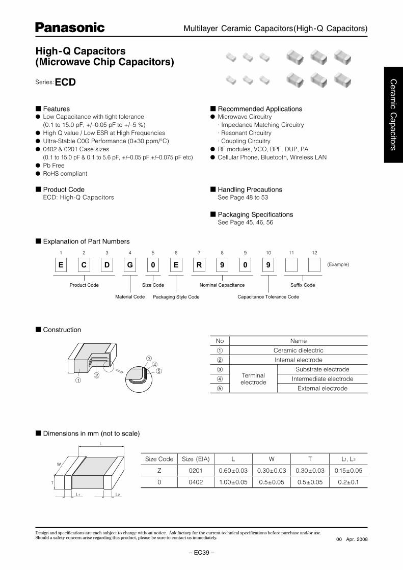
E C D G 0 E R 9 0 9
Size Code Nominal Capacitance
Capacitance Tolerance CodeMaterial Code
(Example)
1 2 3 4 5 6 7 8 9 10 11 12
Suffix Code
Packaging Style Code
Product Code
54
3
21
L
T
W
L1 L2
High-Q Capacitors(Microwave Chip Capacitors)
Series:ECD
Features Low Capacitance with tight tolerance (0.1 to 15.0 pF, +/–0.05 pF to +/–5 %) High Q value / Low ESR at High Frequencies Ultra-Stable C0G Performance (0±30 ppm/°C) 0402 & 0201 Case sizes (0.1 to 15.0 pF & 0.1 to 5.6 pF, +/–0.05 pF,+/–0.075 pF etc) Pb Free RoHS compliant
Recommended Applications Microwave Circuitry · Impedance Matching Circuitry · Resonant Circuitry · Coupling Circuitry RF modules, VCO, BPF, DUP, PA Cellular Phone, Bluetooth, Wireless LAN
Product Code ECD: High-Q Capacitors
Packaging Specifi cations See Page 45, 46, 56
Explanation of Part Numbers
Construction
Dimensions in mm (not to scale)
Size Code Size (EIA) L W T L1, L2
Z 0201 0.60±0.03 0.30±0.03 0.30±0.03 0.15±0.05
0 0402 1.00±0.05 0.5±0.05 0.5±0.05 0.2±0.1
No Name
1 Ceramic dielectric
2 Internal electrode
3Terminal electrode
Substrate electrode
4 Intermediate electrode
5 External electrode
Handling Precautions See Page 48 to 53
Apr. 200800
Design and specifi cations are each subject to change without notice. Ask factory for the current technical specifi cations before purchase and/or use.Should a safety concern arise regarding this product, please be sure to contact us immediately.
Multilayer Ceramic Capacitors(High-Q Capacitors)
– EC40 –
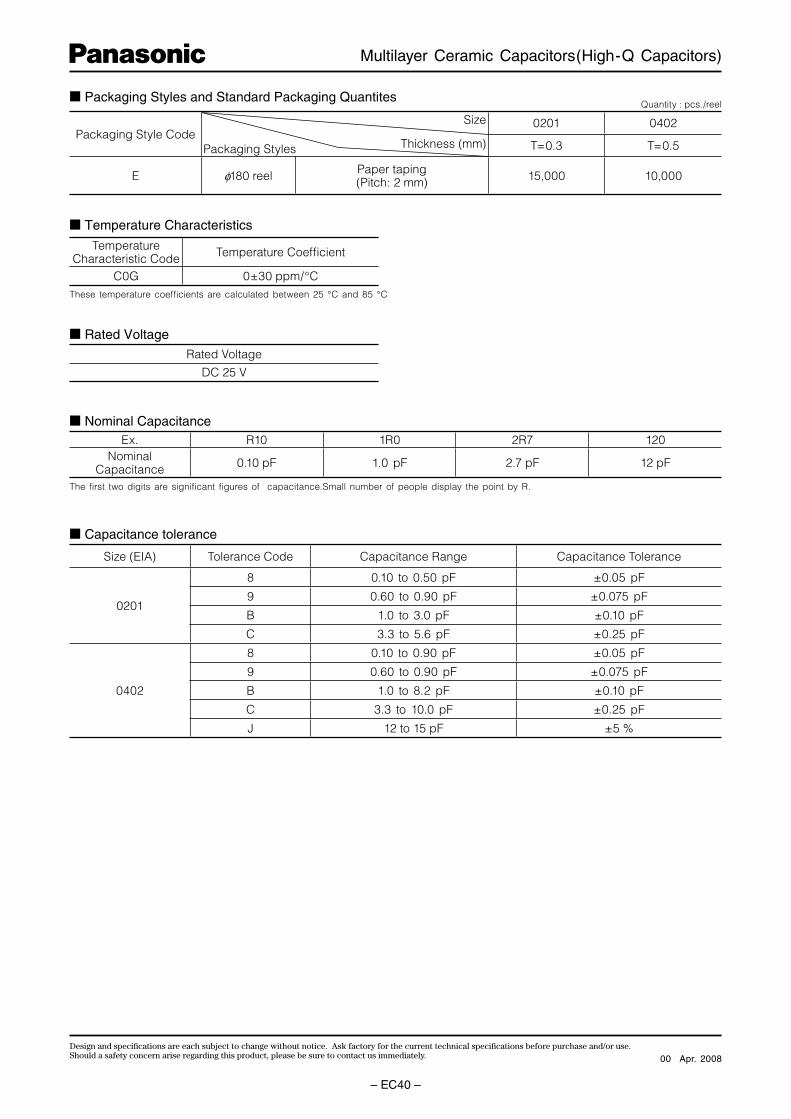
Packaging Style CodeSize
Thickness (mm)Packaging Styles
0201 0402
T=0.3 T=0.5
E φ180 reel Paper taping(Pitch: 2 mm) 15,000 10,000
Packaging Styles and Standard Packaging QuantitesQuantity : pcs./reel
Temperature Characteristic Code Temperature Coeffi cient
C0G 0±30 ppm/°C
Temperature Characteristics
Rated Voltage
Rated Voltage
DC 25 V
Nominal CapacitanceEx. R10 1R0 2R7 120
NominalCapacitance 0.10 pF 1.0 pF 2.7 pF 12 pF
Size (EIA) Tolerance Code Capacitance Range Capacitance Tolerance
0201
8 0.10 to 0.50 pF ±0.05 pF
9 0.60 to 0.90 pF ±0.075 pF
B 1.0 to 3.0 pF ±0.10 pF
C 3.3 to 5.6 pF ±0.25 pF
0402
8 0.10 to 0.90 pF ±0.05 pF
9 0.60 to 0.90 pF ±0.075 pF
B 1.0 to 8.2 pF ±0.10 pF
C 3.3 to 10.0 pF ±0.25 pF
J 12 to 15 pF ±5 %
Capacitance tolerance
These temperature coeffi cients are calculated between 25 °C and 85 °C
The fi rst two digits are signifi cant fi gures of capacitance.Small number of people display the point by R.
Apr. 200800

Design and specifi cations are each subject to change without notice. Ask factory for the current technical specifi cations before purchase and/or use.Should a safety concern arise regarding this product, please be sure to contact us immediately.
Multilayer Ceramic Capacitors(High-Q Capacitors)
– EC41 –
Ceram
ic Capacitors
10
Sample
0.5R
0.3 Size : 02010.5 Size : 0402
PC board
20
45±2 45±2
Ben
din
gVa
lue
Unit : mm
R340
Specifi cations and Testing Methods
Characteristics Specifi cations Test Method
OperatingTemperatureRange
–55 to 125 °C———
Dielectric WithstandingVoltage
No dielectric breakdown and/or damage Test voltage: Rated voltage 300 %Duration: 1 to 5 sCharge/discharge current: 50 mA max.
InsulationResistance (IR)
10000 M min. Measuring voltage: Rated voltageDuration: 60±5 sCharge / Discharge current: 50 mA max.
Capacitance Within the specifi ed tolerance Temperature: 20 +/–2 °CMeasuring Frequency: 1 MHz +/–10 %Measuring Voltage: 0.5 to 5 VrmsDissipation
Factor(tan δ)
tan δ < 0.005 max.
Temperature Characteristics
C0G : 0 +/-30 ppm/°C Maximum capacitance change at stage 1 to 5
Stage Temperature
Stage1 25±2 °C
Stage2 –25±2 °C
Stage3(Reference Temperature)
25±2 °C
Stage4 85±2 °C
Stage5 25±2 °C
Adhesion The terminal electrode shall be free from peeling or signs of peeling.
Applied force : Size : 0201 : 2N Size : 0402 : 5NArrow direction for 10 seconds.
Bending Strength Appearance : no mechanical damage Bending value : 1 mmBending speed : 1 mm/s
Resistance to Solder Heat
Appearance : no mechanical damageI.R. : initial value
Solder temperature : 270±5 °CDipping period : 3.0±0.5 sPreheat condition :
Order Temp. (°C) Time (s)1 80 to 100 120 to 1802 150 to 200 120 to 180
Recovery (Standard condition) : 24 ±2 h
Solderability More than 75 % of the soldered area of both terminal electrodes shall be covered with fresh solder .
Solder bath methodSolder temperature : 230±5 °CDipping period : 4±1 sSolder : H63A (JIS Z 3283)
Standard condition: Temperature 15 to 35 °C, Relative humidity 45 to 75 %.
Apr. 200800

Design and specifi cations are each subject to change without notice. Ask factory for the current technical specifi cations before purchase and/or use.Should a safety concern arise regarding this product, please be sure to contact us immediately.
Multilayer Ceramic Capacitors(High-Q Capacitors)
– EC42 –
1000010000
1000
100
Qva
lue
Qva
lue
Qva
lue
Qva
lue
10
1
1000
100
10
1
10000
1000
100
10
0
0 5 10 150
10000
1000
100
105 10 15
0 1 2 3 4 5 6
Capacitance (pF) Capacitance (pF)
Capacitance (pF) Capacitance (pF)5 10 15
3 GHz2 GHz
1 GHz
Hi-Q
MLCC
0402 size
0201 size
0402 size
3 GHz
2 GHz
1 GHz
at 1 GHzat 1 GHz
Characteristics Specifi cations Test Method
Temperature cycle
Appearance : no mechanical damageI.R. : 1000M min.
Condition of one cycleStep1 : –55 ±3 °C 30±3 min.Step2 : Room temp 3 min.Step3 : 125±3 °C 30±3 min.Step4 : Room temp 3 min.Number of cycles : 5 cyclesRecovery (Standard condition) : 24 ±2 h
MoistureResistance
Appearance : no mechanical damageI.R. : 1000M min.Capacitance Change: Within ±7.5 % or ±0.02 pF whichever is lagertan δ : 0.005 max.
Temperature : 40±2 °CRelative Humidity : 90 to 95 %Test period : 500 +24/0 hRecovery (Standard condition) : 24 ±2 h
MoistureResistantLoading
Appearance : no mechanical damageI.R. : 1000M min.
Temperature : 40±2 °CRelative Humidity : 90 to 95 %Applied voltage : Rated voltageLimit surge current : 50 mA max.Test period : 500 +24/0 hRecovery (Standard condition) : 24 ±2 h
Loading athightemperature
Appearance : no mechanical damageI.R. : 1000M min.
Temperature: 125 °C±3 °CApplied voltage : Rated voltage 200 %Limit surge current : 50 mA max.Test period : 1000 +48/0 hRecovery (Standard condition) : 24 ±2 h
EIA 0201 size
Q value vs. CapacitanceEIA 0402 size
Comparison data of Q value Comparison data of Q value
Measurements performed Boonton34A Resonant Coaxial-Line and represent typical capacitor performance.
Apr. 200800
Design and specifi cations are each subject to change without notice. Ask factory for the current technical specifi cations before purchase and/or use.Should a safety concern arise regarding this product, please be sure to contact us immediately.
Multilayer Ceramic Capacitors(High-Q Capacitors)
– EC43 –
Ceram
ic Capacitors
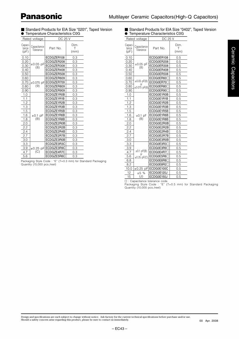
Packaging Style Code : “E” (T=0.3 mm) for Standard PackagingQuantity (15,000 pcs./reel)
Rated voltage DC 25 V
Capaci-tance(pF)
CapacitanceTolerance Part No.
Dim.T
(mm)
0.10
±0.05 pF(8)
ECDGZER108 0.30.20 ECDGZER208 0.30.30 ECDGZER308 0.30.40 ECDGZER408 0.30.50 ECDGZER508 0.30.60
±0.075 pF(9)
ECDGZER609 0.30.70 ECDGZER709 0.30.80 ECDGZER809 0.30.90 ECDGZER909 0.31.0
±0.1 pF(B)
ECDGZE1R0B 0.31.1 ECDGZE1R1B 0.31.2 ECDGZE1R2B 0.31.3 ECDGZE1R3B 0.31.5 ECDGZE1R5B 0.31.6 ECDGZE1R6B 0.31.8 ECDGZE1R8B 0.32.0 ECDGZE2R0B 0.32.2 ECDGZE2R2B 0.32.4 ECDGZE2R4B 0.32.7 ECDGZE2R7B 0.33.0 ECDGZE3R0B 0.33.3
±0.25 pF(C)
ECDGZE3R3C 0.33.9 ECDGZE3R9C 0.34.7 ECDGZE4R7C 0.35.6 ECDGZE5R6C 0.3
Standard Products for EIA Size “0201”, Taped Version Temperature Characteristics C0G
: Capacitance tolerance code.Packaging Style Code : “E” (T=0.5 mm) for Standard Packaging Quantity (10,000 pcs./reel)
Rated voltage DC 25 V
Capaci-tance(pF)
CapacitanceTolerance Part No.
Dim.T
(mm)
0.10
±0.05 pF(8)
ECDG0ER108 0.50.20 ECDG0ER208 0.50.30 ECDG0ER308 0.50.40 ECDG0ER408 0.50.50 ECDG0ER508 0.50.60
±0.05 pF(8)or
±0.075 pF(9)
ECDG0ER60 0.50.70 ECDG0ER70 0.50.80 ECDG0ER80 0.50.90 ECDG0ER90 0.51.0
±0.1 pF(B)
ECDG0E1R0B 0.51.1 ECDG0E1R1B 0.51.2 ECDG0E1R2B 0.51.3 ECDG0E1R3B 0.51.5 ECDG0E1R5B 0.51.6 ECDG0E1R6B 0.51.8 ECDG0E1R8B 0.52.0 ECDG0E2R0B 0.52.2 ECDG0E2R2B 0.52.4 ECDG0E2R4B 0.52.7 ECDG0E2R7B 0.53.0 ECDG0E3R0B 0.53.3
±0.1 pF(B)or
±0.25 pF(C)
ECDG0E3R3 0.53.9 ECDG0E3R9 0.54.7 ECDG0E4R7 0.55.6 ECDG0E5R6 0.56.8 ECDG0E6R8 0.58.2 ECDG0E8R2 0.510.0 ±0.25 pF ECDG0E100C 0.512 ±5 %
(J)ECDG0E120J 0.5
15 ECDG0E150J 0.5
Standard Products for EIA Size “0402”, Taped Version Temperature Characteristics C0G
Apr. 200800
Design and specifi cations are each subject to change without notice. Ask factory for the current technical specifi cations before purchase and/or use.Should a safety concern arise regarding this product, please be sure to contact us immediately.
Multilayer Ceramic Capacitors(High-Q Capacitors)
– EC44 –
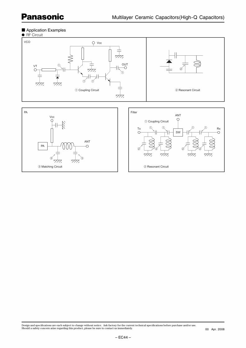
VCO
2 Resonant Circuit1 Coupling Circuit
3 Matching Circuit
OUT
Vcc
Vcc
PA
VT
ANT
Tx Rx
ANT
SW
1 Coupling Circuit
2 Resonant Circuit
2
PA Filter
1
3
2 2 2
1 1 1 1
2
1
1
3
1
Application Examples RF Circuit
Apr. 200800