REAR SUSPENSION E SUSPENSION - boredmder - …boredmder.com/FSMs/Nissan/Murano/2007/RSU.pdfRSU-8...
18
RSU-1 REAR SUSPENSION E SUSPENSION CONTENTS C D F G H I J K L M SECTION A B RSU Revision: 2006 July 2007 Murano REAR SUSPENSION PRECAUTIONS ......................................................... 2 Cautions .................................................................. 2 PREPARATION .......................................................... 3 Special Service Tools .............................................. 3 Commercial Service Tools ....................................... 3 NOISE, VIBRATION AND HARSHNESS (NVH) TROUBLESHOOTING ............................................... 4 NVH Troubleshooting Chart .................................... 4 REAR SUSPENSION ASSEMBLY ............................ 5 On-Vehicle Inspection ............................................. 5 INSPECTION OF SUSPENSION ARM BALL JOINT END PLAY ................................................ 5 SHOCK ABSORBER INSPECTION .................... 5 Wheel Alignment Inspection .................................... 5 DESCRIPTION ..................................................... 5 PRELIMINARY CHECK ....................................... 5 GENERAL INFORMATION AND RECOMMEN- DATIONS ............................................................. 5 THE ALIGNMENT PROCESS ............................. 6 CAMBER INSPECTION ....................................... 6 TOE-IN ................................................................. 6 Components ............................................................ 7 Removal and Installation ......................................... 8 REMOVAL ............................................................ 8 INSTALLATION .................................................... 8 SHOCK ABSORBER ................................................. 9 Removal and Installation ......................................... 9 REMOVAL ............................................................ 9 INSPECTION AFTER REMOVAL ........................ 9 INSTALLATION .................................................... 9 Disassembly and Assembly .................................... 9 DISASSEMBLY .................................................... 9 INSPECTION AFTER DISASSEMBLY .............. 10 ASSEMBLY ........................................................ 10 SUSPENSION ARM ................................................. 11 Removal and Installation ....................................... 11 REMOVAL .......................................................... 11 INSPECTION AFTER REMOVAL ...................... 11 INSTALLATION .................................................. 12 RADIUS ROD ........................................................... 13 Removal and Installation ....................................... 13 REMOVAL .......................................................... 13 INSPECTION AFTER REMOVAL ...................... 13 INSTALLATION .................................................. 13 FRONT LOWER LINK ............................................. 14 Removal and Installation ....................................... 14 REMOVAL .......................................................... 14 INSPECTION AFTER REMOVAL ...................... 14 INSTALLATION .................................................. 14 REAR LOWER LINK & COIL SPRING .................... 15 Removal and Installation ....................................... 15 REMOVAL .......................................................... 15 INSPECTION AFTER REMOVAL ...................... 15 INSTALLATION .................................................. 15 STABILIZER BAR .................................................... 16 Removal and Installation ....................................... 16 REMOVAL .......................................................... 16 INSPECTION AFTER REMOVAL ...................... 16 INSTALLATION .................................................. 16 REAR SUSPENSION MEMBER .............................. 17 Removal and Installation ....................................... 17 REMOVAL .......................................................... 17 INSPECTION AFTER REMOVAL ...................... 17 INSTALLATION .................................................. 17 SERVICE DATA AND SPECIFICATIONS (SDS) ..... 18 Wheel Alignment (Unladen*) ................................. 18 Ball Joint ................................................................ 18 Wheelarch Height (Unladen*) ................................ 18
Transcript of REAR SUSPENSION E SUSPENSION - boredmder - …boredmder.com/FSMs/Nissan/Murano/2007/RSU.pdfRSU-8...
RSU-1
REAR SUSPENSION
E SUSPENSION
CONTENTS
C
D
F
G
H
I
J
K
L
M
SECTION
A
B
RSU
Revision: 2006 July 2007 Murano
REAR SUSPENSION
PRECAUTIONS .......................................................... 2Cautions ................................................................... 2
PREPARATION ........................................................... 3Special Service Tools ............................................... 3Commercial Service Tools ........................................ 3
NOISE, VIBRATION AND HARSHNESS (NVH) TROUBLESHOOTING ................................................ 4
NVH Troubleshooting Chart ..................................... 4REAR SUSPENSION ASSEMBLY ............................. 5
On-Vehicle Inspection .............................................. 5INSPECTION OF SUSPENSION ARM BALL JOINT END PLAY ................................................. 5SHOCK ABSORBER INSPECTION ..................... 5
Wheel Alignment Inspection ..................................... 5DESCRIPTION ...................................................... 5PRELIMINARY CHECK ........................................ 5GENERAL INFORMATION AND RECOMMEN-DATIONS .............................................................. 5THE ALIGNMENT PROCESS .............................. 6CAMBER INSPECTION ........................................ 6TOE-IN .................................................................. 6
Components ............................................................. 7Removal and Installation .......................................... 8
REMOVAL ............................................................. 8INSTALLATION ..................................................... 8
SHOCK ABSORBER .................................................. 9Removal and Installation .......................................... 9
REMOVAL ............................................................. 9INSPECTION AFTER REMOVAL ......................... 9INSTALLATION ..................................................... 9
Disassembly and Assembly ..................................... 9DISASSEMBLY ..................................................... 9INSPECTION AFTER DISASSEMBLY ............... 10ASSEMBLY ......................................................... 10
SUSPENSION ARM .................................................. 11Removal and Installation ........................................ 11
REMOVAL ........................................................... 11INSPECTION AFTER REMOVAL ....................... 11INSTALLATION ................................................... 12
RADIUS ROD ............................................................ 13Removal and Installation ........................................ 13
REMOVAL ........................................................... 13INSPECTION AFTER REMOVAL ....................... 13INSTALLATION ................................................... 13
FRONT LOWER LINK .............................................. 14Removal and Installation ........................................ 14
REMOVAL ........................................................... 14INSPECTION AFTER REMOVAL ....................... 14INSTALLATION ................................................... 14
REAR LOWER LINK & COIL SPRING ..................... 15Removal and Installation ........................................ 15
REMOVAL ........................................................... 15INSPECTION AFTER REMOVAL ....................... 15INSTALLATION ................................................... 15
STABILIZER BAR ..................................................... 16Removal and Installation ........................................ 16
REMOVAL ........................................................... 16INSPECTION AFTER REMOVAL ....................... 16INSTALLATION ................................................... 16
REAR SUSPENSION MEMBER ............................... 17Removal and Installation ........................................ 17
REMOVAL ........................................................... 17INSPECTION AFTER REMOVAL ....................... 17INSTALLATION ................................................... 17
SERVICE DATA AND SPECIFICATIONS (SDS) ...... 18Wheel Alignment (Unladen*) .................................. 18Ball Joint ................................................................. 18Wheelarch Height (Unladen*) ................................. 18

RSU-2
PRECAUTIONS
Revision: 2006 July 2007 Murano
PRECAUTIONS PFP:00001
Cautions NES0008L
● When installing rubber bushings, final tightening must be carried out under unladen conditions with tireson level ground. Oil will shorten the life of rubber bushings. Be sure to wipe off any spilled oil.
● Unladen conditions mean that fuel, engine coolant and lubricant are full. Spare tire, jack, hand tools andmats are in designated positions.
● After servicing suspension parts, be sure to check wheel alignment.● Caulking nuts are not reusable. Always use new ones when installing. Since new caulking nuts are pre-
oiled, tighten as they are.
PREPARATION
RSU-3
C
D
F
G
H
I
J
K
L
M
A
B
RSU
Revision: 2006 July 2007 Murano
PREPARATION PFP:00002
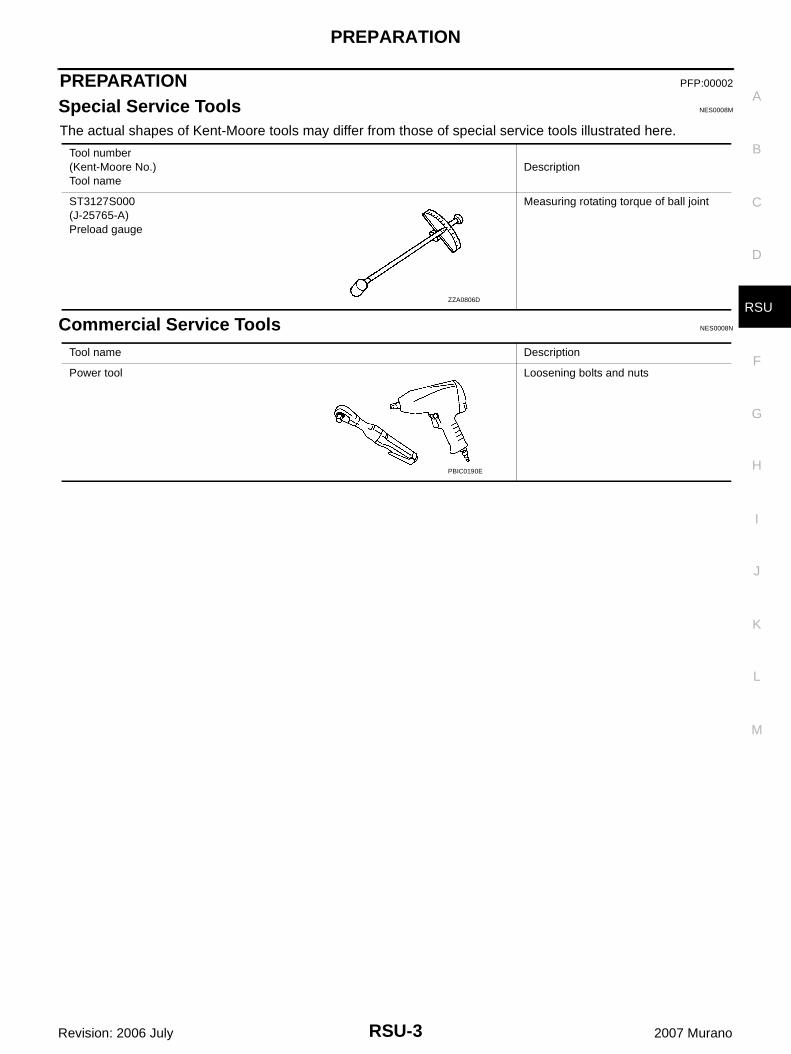
Special Service Tools NES0008M
The actual shapes of Kent-Moore tools may differ from those of special service tools illustrated here.
Commercial Service Tools NES0008N
Tool number(Kent-Moore No.)Tool name
Description
ST3127S000(J-25765-A)Preload gauge
Measuring rotating torque of ball joint
ZZA0806D
Tool name Description
Power tool Loosening bolts and nuts
PBIC0190E
RSU-4
NOISE, VIBRATION AND HARSHNESS (NVH) TROUBLESHOOTING
Revision: 2006 July 2007 Murano
NOISE, VIBRATION AND HARSHNESS (NVH) TROUBLESHOOTING PFP:00003
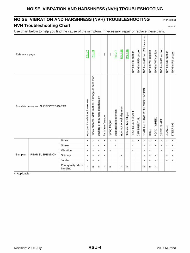
NVH Troubleshooting Chart NES0008O
Use chart below to help you find the cause of the symptom. If necessary, repair or replace these parts.
×: Applicable
Reference page
RS
U-7
RS
U-9
— — —
RS
U-7
RS
U-1
8
RS
U-1
6
NV
H in
PR
sec
tion
NV
H in
RF
D s
ectio
n
NV
H in
RA
X a
nd R
SU
sec
tions
NV
H in
WT
sec
tion
NV
H in
WT
sec
tion
NV
H in
RA
X s
ectio
n
NV
H in
BR
sec
tion
NV
H in
PS
sec
tion
Possible cause and SUSPECTED PARTS
Impr
oper
inst
alla
tion,
loos
enes
s
Sho
ck a
bsor
ber
defo
rmat
ion,
dam
age
or d
efle
ctio
n
Bus
hing
or
mou
ntin
g de
terio
ratio
n
Par
ts in
terf
eren
ce
Spr
ing
fatig
ue
Sus
pens
ion
loos
enes
s
Inco
rrec
t whe
el a
lignm
ent
Sta
biliz
er b
ar fa
tigue
PR
OP
ELL
ER
SH
AF
T
DIF
FE
RE
NT
IAL
RE
AR
AX
LE A
ND
RE
AR
SU
SP
EN
SIO
N
TIR
ES
RO
AD
W
HE
EL
DR
IVE
SH
AF
T
BR
AK
ES
ST
EE
RIN
G
Symptom REAR SUSPENSION
Noise × × × × × × × × × × × × × ×
Shake × × × × × × × × × × × ×
Vibration × × × × × × × × × ×
Shimmy × × × × × × × × × ×
Judder × × × × × × × ×
Poor quality ride or handling
× × × × × × × × × ×
REAR SUSPENSION ASSEMBLY
RSU-5
C
D
F
G
H
I
J
K
L
M
A
B
RSU
Revision: 2006 July 2007 Murano
REAR SUSPENSION ASSEMBLY PFP:55020
On-Vehicle Inspection NES0008P
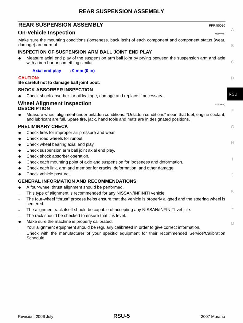
Make sure the mounting conditions (looseness, back lash) of each component and component status (wear,damage) are normal.
INSPECTION OF SUSPENSION ARM BALL JOINT END PLAY● Measure axial end play of the suspension arm ball joint by prying between the suspension arm and axle
with a iron bar or something similar.
CAUTION:Be careful not to damage ball joint boot.
SHOCK ABSORBER INSPECTION● Check shock absorber for oil leakage, damage and replace if necessary.
Wheel Alignment Inspection NES0008Q
DESCRIPTION● Measure wheel alignment under unladen conditions. “Unladen conditions” mean that fuel, engine coolant,
and lubricant are full. Spare tire, jack, hand tools and mats are in designated positions.
PRELIMINARY CHECK● Check tires for improper air pressure and wear.● Check road wheels for runout.● Check wheel bearing axial end play.● Check suspension arm ball joint axial end play.● Check shock absorber operation.● Check each mounting point of axle and suspension for looseness and deformation.● Check each link, arm and member for cracks, deformation, and other damage.● Check vehicle posture.
GENERAL INFORMATION AND RECOMMENDATIONS● A four-wheel thrust alignment should be performed.– This type of alignment is recommended for any NISSAN/INFINITI vehicle.– The four-wheel “thrust” process helps ensure that the vehicle is properly aligned and the steering wheel is
centered.– The alignment rack itself should be capable of accepting any NISSAN/INFINITI vehicle.– The rack should be checked to ensure that it is level.● Make sure the machine is properly calibrated.– Your alignment equipment should be regularly calibrated in order to give correct information.– Check with the manufacturer of your specific equipment for their recommended Service/Calibration
Schedule.
Axial end play : 0 mm (0 in)
RSU-6
REAR SUSPENSION ASSEMBLY
Revision: 2006 July 2007 Murano
THE ALIGNMENT PROCESSIMPORTANT:Use only the alignment specifications listed in this Service Manual.● When displaying the alignment settings, many alignment machines use “indicators”: (Green/red, plus or
minus, Go/No Go). Do NOT use these indicators.– The alignment specifications programmed into your machine that operate these indicators may not be cor-
rect.– This may result in an ERROR.● Some newer alignment machines are equipped with an optional “Rolling Compensation” method to “com-
pensate” the sensors (alignment targets or head units). DO NOT use this “Rolling Compensation”method.
– Use the “Jacking Compensation Method”. After installing the alignment targets or head units, raise thevehicle and rotate the wheels 1/2 turn both ways.
– See Instructions in the alignment machine you're using for more information on this.
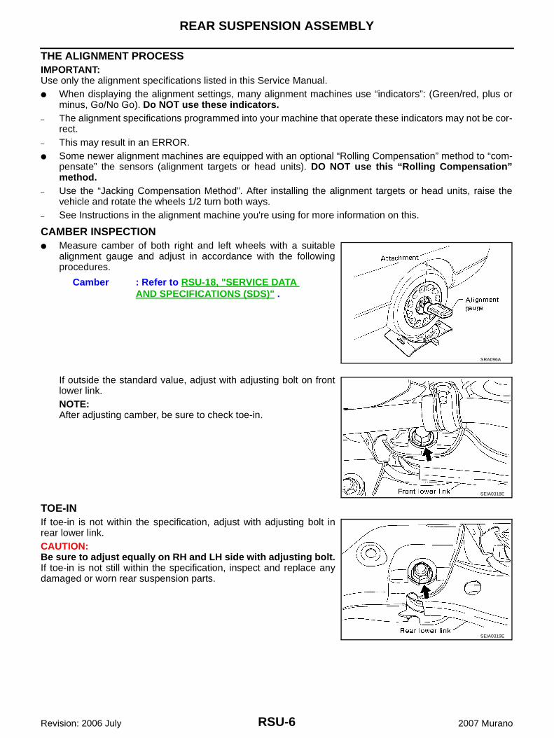
CAMBER INSPECTION● Measure camber of both right and left wheels with a suitable
alignment gauge and adjust in accordance with the followingprocedures.
If outside the standard value, adjust with adjusting bolt on frontlower link.NOTE:After adjusting camber, be sure to check toe-in.
TOE-INIf toe-in is not within the specification, adjust with adjusting bolt inrear lower link.CAUTION:Be sure to adjust equally on RH and LH side with adjusting bolt.If toe-in is not still within the specification, inspect and replace anydamaged or worn rear suspension parts.
Camber : Refer to RSU-18, "SERVICE DATA AND SPECIFICATIONS (SDS)" .
SRA096A
SEIA0318E
SEIA0319E
REAR SUSPENSION ASSEMBLY
RSU-7
C
D
F
G
H
I
J
K
L
M
A
B
RSU
Revision: 2006 July 2007 Murano
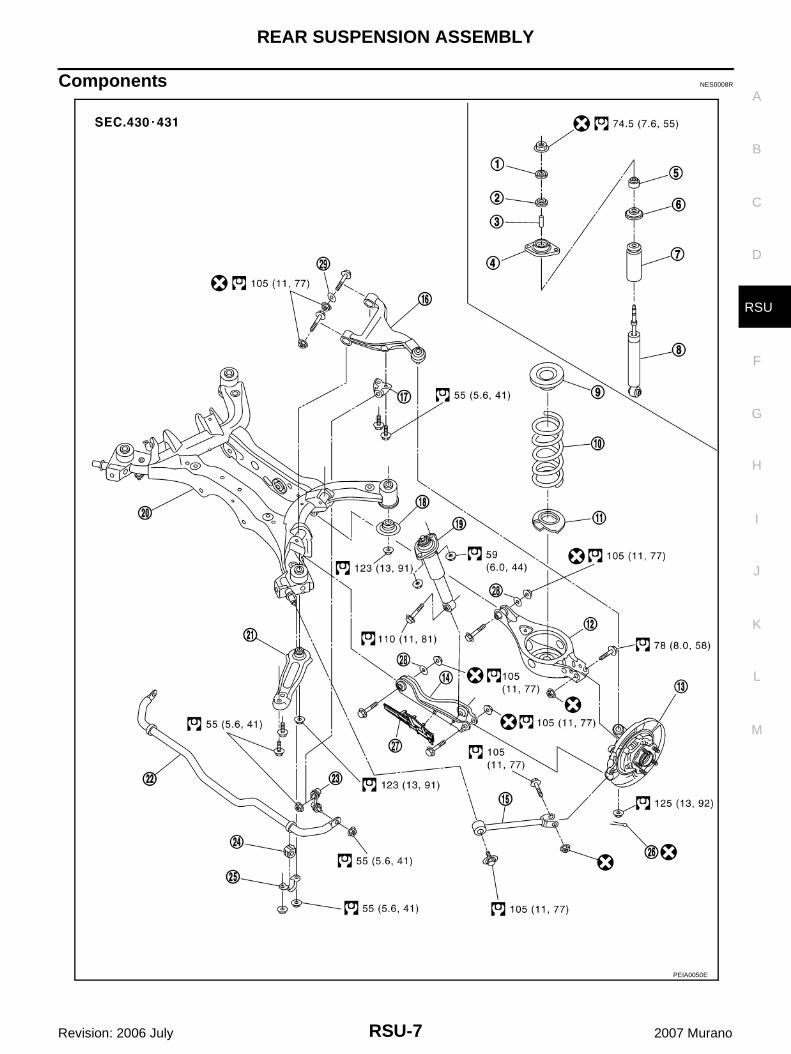
Components NES0008R
PEIA0050E
RSU-8
REAR SUSPENSION ASSEMBLY
Revision: 2006 July 2007 Murano
Removal and Installation NES0008S
REMOVAL1. Remove tires from vehicle with power tool.2. Remove brake caliper with power tool. Hang it in a place where it will not interfere with work. Refer to BR-
34, "Removal and Installation of Brake Caliper Assembly" . Then remove disc rotor.CAUTION:Avoid depressing brake pedal while brake caliper is removed.
3. Remove wheel sensor from axle. Refer to BRC-97, "WHEEL SENSORS" .4. Remove center muffler and main muffler. Refer to EX-3, "Removal and Installation" .5. Remove propeller shaft (AWD models).6. Remove harness from rear final drive, suspension member and suspension arm.7. Separate the attachment between parking brake cable and vehicle. Refer to PB-4, "PARKING BRAKE
CONTROL" .8. Remove rear lower link and coil spring. Refer to RSU-15, "Removal and Installation" .9. Remove fixing nuts in upper side of mounting seal bracket. 10. Set jack under rear final drive (AWD models) or suspension member (2WD models).11. Remove fixing bolts and nuts of member stay, then remove member stay from vehicle and suspension
member.12. Remove fixing nuts in rear side of suspension member, then remove rebound stopper.13. Slowly lower jack, remove rear suspension assembly.
INSTALLATIONRefer to RSU-7, "Components" for tightening torque. Install in the reverse order of removal.CAUTION:Refer to components and do not reuse non-reusable parts.● Perform final tightening of installation position of links (rubber bushing) under unladen conditions with tires
on level ground. Check wheel alignment. Refer to RSU-18, "Wheel Alignment (Unladen*)" .● After installation, check parking brake operation. Refer to PB-3, "PARKING BRAKE SYSTEM" .● After installation, check condition of wheel sensor harness. Refer to BRC-40, "WHEEL SENSORS" .
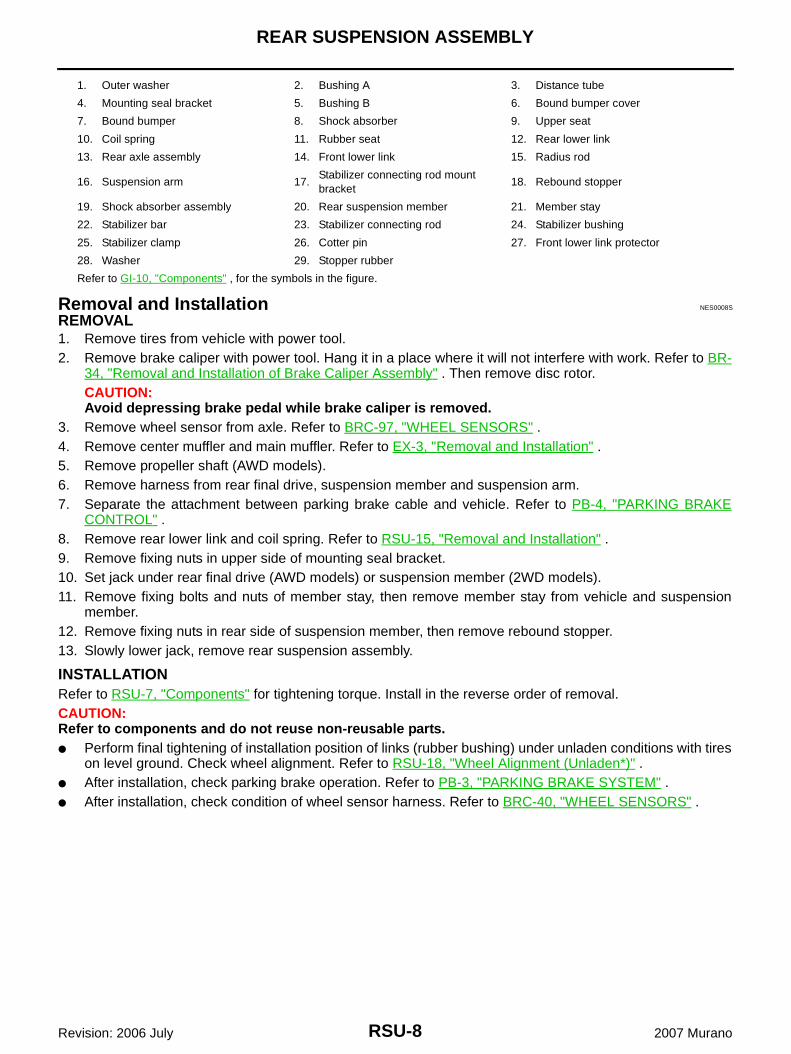
1. Outer washer 2. Bushing A 3. Distance tube
4. Mounting seal bracket 5. Bushing B 6. Bound bumper cover
7. Bound bumper 8. Shock absorber 9. Upper seat
10. Coil spring 11. Rubber seat 12. Rear lower link
13. Rear axle assembly 14. Front lower link 15. Radius rod
16. Suspension arm 17.Stabilizer connecting rod mount bracket
18. Rebound stopper
19. Shock absorber assembly 20. Rear suspension member 21. Member stay
22. Stabilizer bar 23. Stabilizer connecting rod 24. Stabilizer bushing
25. Stabilizer clamp 26. Cotter pin 27. Front lower link protector
28. Washer 29. Stopper rubber
Refer to GI-10, "Components" , for the symbols in the figure.

SHOCK ABSORBER
RSU-9
C
D
F
G
H
I
J
K
L
M
A
B
RSU
Revision: 2006 July 2007 Murano
SHOCK ABSORBER PFP:56210
Removal and Installation NES0008T
REMOVAL1. Remove tires from vehicle with power tool.2. Remove fixing bolt in lower side of shock absorber assembly with power tool.3. Remove mounting seal bracket fixing nuts of shock absorber
upper side with power tool and remove shock absorber assem-bly from vehicle.
INSPECTION AFTER REMOVAL● Check shock absorber for deformation, cracks or damage, and replace if necessary.● Check piston rod for damage, uneven wear or distortion, and replace if necessary.● Check welded and sealed areas for oil leakage, and replace if necessary.● Check seal of mount seal bracket. If any crack, deformation or deterioration is found, replace the mount
seal bracket as assembly.
INSTALLATION● Refer to RSU-7, "Components" for tightening torque. Install in the reverse order of removal.
CAUTION:Refer to component parts location and do not reuse non-reusable parts.
● Perform final tightening of shock absorber lower side (rubber bushing) under unladen conditions with tireson level ground. Check wheel alignment. Refer to RSU-18, "Wheel Alignment (Unladen*)" .
Disassembly and Assembly NES0008U
DISASSEMBLYCAUTION:Make sure piston rod on shock absorber is not damaged when removing components from shockabsorber.1. Wrap a shop cloth around lower side of shock absorber and fix it in a vise.
CAUTION:Do not set the cylindrical part of shock absorber in vise.
2. Secure piston rod tip so that piston rod does not turn, andremove piston rod lock nut.
3. Remove outer washer, bushing A, distance tube, mounting sealbracket, bushing B and bound bumper cover from shockabsorber.
4. Remove bound bumper from bound bumper cover.
FA-0274D
SEIA0218J

RSU-10
SHOCK ABSORBER
Revision: 2006 July 2007 Murano
INSPECTION AFTER DISASSEMBLYBound Bumper and Bushing● Check bound bumper and bushing for cracks, deformation or other damage. Replace if necessary.
ASSEMBLY● Refer to RSU-7, "Components" for tightening torque. Install in the reverse order of removal.
CAUTION:● Refer to component parts location and do not reuse non-reusable parts.● Make sure piston rod on shock absorber is not damaged when assembling components to
shock absorber.
SUSPENSION ARM
RSU-11
C
D
F
G
H
I
J
K
L
M
A
B
RSU
Revision: 2006 July 2007 Murano
SUSPENSION ARM PFP:55501
Removal and Installation NES0008V
REMOVAL1. Remove tires from vehicle with power tool.2. Remove coil spring. Refer to RSU-15, "REAR LOWER LINK & COIL SPRING" .3. Remove wheel sensor and sensor harness from axle and suspension arm. Refer to BRC-40, "WHEEL
SENSORS" .4. Remove stabilizer connecting rod mounting bracket from suspension arm.5. Set jack under front lower link.6. Remove fuel filler tube fixing bolt (left side only). Refer to FL-4, "FUEL LEVEL SENSOR UNIT, FUEL FIL-
TER AND FUEL PUMP ASSEMBLY" .7. Remove fixing nuts and bolts between suspension arm and rear suspension member.8. Remove cotter pin of suspension arm ball joint, and loosen nut.9. Use a ball joint remover (suitable tool) to remove suspension arm from axle. Be careful not to damage ball
joint boot.CAUTION:To prevent damage to ball joint threads and to prevent ball joint remover (suitable tool) from com-ing off, temporarily tighten lock nuts.
10. Remove suspension arm from vehicle.
INSPECTION AFTER REMOVALVisual Inspection● Check suspension arm and bushing for deformation, cracks, or other damage. If any non-standard condi-
tion is found, replace it.● Check boot of ball joint for cracks, or other damage, and also for grease leakage.
Ball Joint Inspection● Manually move ball stud to confirm it moves smoothly with no binding.
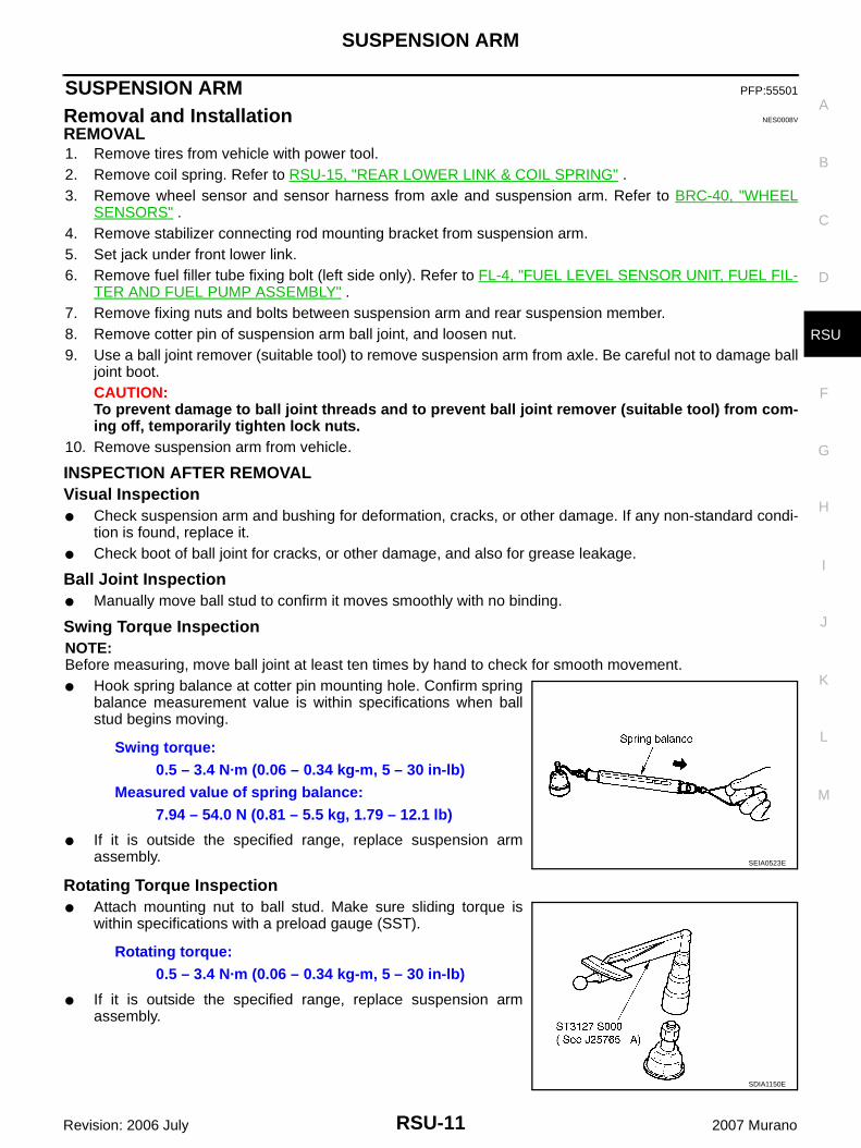
Swing Torque InspectionNOTE:Before measuring, move ball joint at least ten times by hand to check for smooth movement.● Hook spring balance at cotter pin mounting hole. Confirm spring
balance measurement value is within specifications when ballstud begins moving.
● If it is outside the specified range, replace suspension armassembly.
Rotating Torque Inspection● Attach mounting nut to ball stud. Make sure sliding torque is
within specifications with a preload gauge (SST).
● If it is outside the specified range, replace suspension armassembly.
Swing torque:0.5 – 3.4 N·m (0.06 – 0.34 kg-m, 5 – 30 in-lb)
Measured value of spring balance:7.94 – 54.0 N (0.81 – 5.5 kg, 1.79 – 12.1 lb)
SEIA0523E
Rotating torque:0.5 – 3.4 N·m (0.06 – 0.34 kg-m, 5 – 30 in-lb)
SDIA1150E
RSU-12
SUSPENSION ARM
Revision: 2006 July 2007 Murano
Axial End Play Inspection● Move tip of ball joint in axial direction to check for looseness.
● If it is outside the specified range, replace suspension arm assembly.
INSTALLATION● Refer to RSU-7, "Components" for tightening torque. Install in the reverse order of removal.
CAUTION:Refer to component parts location and do not reuse non-reusable parts.
● Perform final tightening of rear suspension member installation position (rubber bushing) under unladenconditions with tires on level ground. Check wheel alignment. Refer to RSU-18, "Wheel Alignment(Unladen*)" .
Axial end play : 0 mm (0 in)
RADIUS ROD
RSU-13
C
D
F
G
H
I
J
K
L
M
A
B
RSU
Revision: 2006 July 2007 Murano
RADIUS ROD PFP:55110
Removal and Installation NES0008W
REMOVAL1. Remove tires from vehicle with power tool.2. Remove coil spring. Refer to RSU-15, "REAR LOWER LINK & COIL SPRING" .3. Remove wheel sensor and sensor harness from axle and suspension arm. Refer to BRC-40, "WHEEL
SENSORS" .4. Remove fixing bolt in lower side of shock absorber with power tool.5. Remove fixing bolt and nut in axle side of front lower link with power tool.6. Loosen fixing bolt and nut of front lower link in side of suspension member.7. Remove fixing bolt and nut in axle side of radius rod.8. Remove fixing bolt in rear suspension member side of radius rod with power tool, then remove radius rod
from vehicle.
INSPECTION AFTER REMOVAL● Check radius rod and bushing for any deformation, crack, or damage. Replace if necessary.
INSTALLATION● Refer to RSU-7, "Components" for tightening torque. Tighten in the reverse order of removal.
CAUTION:Refer to component parts location and do not reuse non-reusable parts.
● Perform final tightening of rear suspension member and axle installation position (rubber bushing) underunladen conditions with tires on level ground. Check wheel alignment. Refer to RSU-5, "Wheel AlignmentInspection" .
RSU-14
FRONT LOWER LINK
Revision: 2006 July 2007 Murano
FRONT LOWER LINK PFP:55110
Removal and Installation NES0008X
REMOVAL1. Remove tires from vehicle with power tool.2. Remove coil spring. Refer to RSU-15, "Removal and Installation" .3. Remove wheel sensor and sensor harness from axle and suspension arm. Refer to BRC-40, "WHEEL
SENSORS" .4. Remove fixing bolt between front lower link and shock absorber.5. Remove stabilizer bushing and clamp from suspension member.6. Remove fixing nut and bolt between front lower link and rear suspension member with power tool.7. Remove fixing nut and bolt between front lower link and axle.8. Remove front lower link from vehicle.9. Remove front lower link protector.
INSPECTION AFTER REMOVAL● Check front lower link and bushing for any deformation, crack, or damage. Replace if necessary.
INSTALLATION● Refer to RSU-7, "Components" for tightening torque. Install in the reverse order of removal.
CAUTION:Refer to component parts location and do not reuse non-reusable parts.
● Perform final tightening of rear suspension member and axle installation position (rubber bushing) underunladen conditions with tires on level ground. Check wheel alignment. Refer to RSU-18, "Wheel Align-ment (Unladen*)" .
REAR LOWER LINK & COIL SPRING
RSU-15
C
D
F
G
H
I
J
K
L
M
A
B
RSU
Revision: 2006 July 2007 Murano
REAR LOWER LINK & COIL SPRING PFP:551B0
Removal and Installation NES0008Y
REMOVAL1. Remove tires from vehicle with power tool.2. Set jack under rear lower link.3. Loosen fixing bolt and nut between rear lower link and suspension member, and then remove fixing bolt
and nut between rear axle and rear lower link with power tool.4. Slowly lower jack, then remove upper seat, coil spring and rubber seat from rear lower link.5. Remove fixing bolt and nut between rear suspension member and rear lower link with power tool.
INSPECTION AFTER REMOVAL● Check rear lower link, bushing and coil spring for deformation, cracks, and damage. Replace rear lower
link and coil spring if necessary.
INSTALLATION● Refer to RSU-7, "Components" for tightening torque. Install in the reverse order of removal.
CAUTION:Refer to component parts location and do not reuse non-reusable parts.
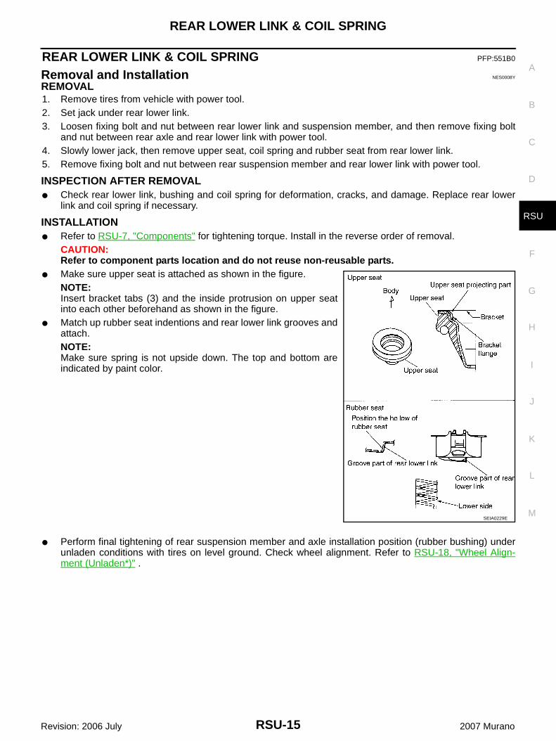
● Make sure upper seat is attached as shown in the figure.NOTE:Insert bracket tabs (3) and the inside protrusion on upper seatinto each other beforehand as shown in the figure.
● Match up rubber seat indentions and rear lower link grooves andattach.NOTE:Make sure spring is not upside down. The top and bottom areindicated by paint color.
● Perform final tightening of rear suspension member and axle installation position (rubber bushing) underunladen conditions with tires on level ground. Check wheel alignment. Refer to RSU-18, "Wheel Align-ment (Unladen*)" .
SEIA0229E
RSU-16
STABILIZER BAR
Revision: 2006 July 2007 Murano
STABILIZER BAR PFP:56230
Removal and Installation NES0008Z
REMOVAL1. Remove tires from vehicle with power tool.2. Remove lower side fixing nut on stabilizer connecting rod and remove stabilizer connecting rod from stabi-
lizer bar.3. Remove fixing nut on stabilizer clamp and remove stabilizer from vehicle with power tool.
INSPECTION AFTER REMOVAL● Check stabilizer bar, stabilizer bushing, stabilizer clamp, stabilizer connecting rod, stabilizer connecting
rod mounting bracket for any deformation, crack or damage. Replace if necessary.
INSTALLATION● Refer to RSU-7, "Components" for tightening torque. Install in the reverse order of removal.
CAUTION:Refer to component parts location and do not reuse non-reusable parts.
● When the bushing and clamp are installed to stabilizer bar, position the bushing and clamp inside of theside slip prevention clamp.

REAR SUSPENSION MEMBER
RSU-17
C
D
F
G
H
I
J
K
L
M
A
B
RSU
Revision: 2006 July 2007 Murano
REAR SUSPENSION MEMBER PFP:55501
Removal and Installation NES00090
REMOVAL1. Remove tires from vehicle with power tool.2. Remove brake caliper with power tool. Hang it in a place where it will not interfere with work. Refer to BR-
34, "Removal and Installation of Brake Caliper Assembly" . Then remove disc rotor.CAUTION:Avoid depressing brake pedal while brake caliper is removed.
3. Remove wheel sensor and sensor harness from axle and suspension arm. Refer to BRC-40, "WHEELSENSORS" .
4. Remove center muffler and main muffler. Refer to EX-3, "Removal and Installation" .5. Remove stabilizer bar. Refer to RSU-16, "Removal and Installation" .6. Remove drive shaft (AWD models). Refer to RAX-7, "Removal and Installation" .7. Remove propeller shaft (AWD models). Refer to PR-5, "Removal and Installation" .8. Remove harness from rear final drive (AWD models) and rear suspension member.9. Remove final drive. Refer to RFD-14, "REAR FINAL DRIVE ASSEMBLY" .10. Separate the attachment between parking brake cable and vehicle and rear suspension member.11. Remove rear lower link and coil spring. Refer to RSU-15, "Removal and Installation" .12. Remove fixing bolt in lower side of shock absorber.13. Set jack under rear suspension member.14. Remove fixing bolts and nuts of member stay, then remove member stay from vehicle and rear suspen-
sion member.15. Remove fixing nuts in rear side of rear suspension member, then remove rebound stopper.16. Slowly lower jack, then remove rear suspension member, suspension arm, radius rod, front lower link and
axle from vehicle as a unit.17. Remove fixing bolts and nuts, then remove suspension arm, front lower link, and radius rod from rear sus-
pension member.18. Remove electric controlled coupling breather hose from rear suspension member. Refer to RFD-12,
"Removal and Installation" .
INSPECTION AFTER REMOVAL● Check rear suspension member for deformation, cracks, and other damage and replace if necessary.
INSTALLATIONRefer to RSU-7, "Components" , for tightening torque. Install in the reverse order of removal.CAUTION:Refer to component parts location and do not reuse non-reusable parts.● Perform final tightening of installation position of links (rubber bushing) under unladen conditions with tires
on level ground. Check wheel alignment. Refer to RSU-5, "Wheel Alignment Inspection" .● After installation, check parking brake operation. Refer to PB-3, "PARKING BRAKE SYSTEM" .● After installation, check condition of wheel sensor harness. Refer to BRC-40, "WHEEL SENSORS" .
RSU-18
SERVICE DATA AND SPECIFICATIONS (SDS)
Revision: 2006 July 2007 Murano
SERVICE DATA AND SPECIFICATIONS (SDS) PFP:00030
Wheel Alignment (Unladen*) NES00091
*: Fuel, engine coolant and lubricant are oil full. Spare tire, jack, hand tools and mats are in designated positions.
Ball Joint NES00092
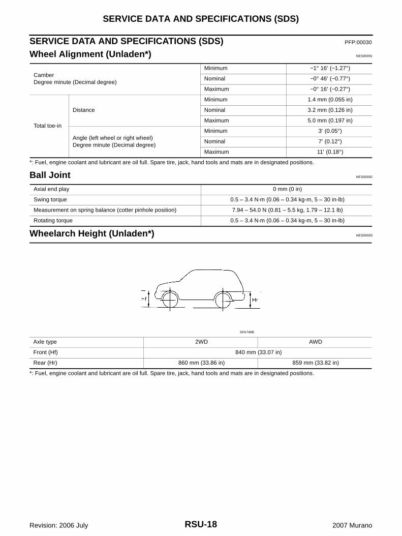
Wheelarch Height (Unladen*) NES00093
*: Fuel, engine coolant and lubricant are oil full. Spare tire, jack, hand tools and mats are in designated positions.
CamberDegree minute (Decimal degree)
Minimum −1° 16′ (−1.27°)
Nominal −0° 46′ (−0.77°)
Maximum −0° 16′ (−0.27°)
Total toe-in
Distance
Minimum 1.4 mm (0.055 in)
Nominal 3.2 mm (0.126 in)
Maximum 5.0 mm (0.197 in)
Angle (left wheel or right wheel)Degree minute (Decimal degree)
Minimum 3′ (0.05°)
Nominal 7′ (0.12°)
Maximum 11′ (0.18°)
Axial end play 0 mm (0 in)
Swing torque 0.5 – 3.4 N·m (0.06 – 0.34 kg-m, 5 – 30 in-lb)
Measurement on spring balance (cotter pinhole position) 7.94 – 54.0 N (0.81 – 5.5 kg, 1.79 – 12.1 lb)
Rotating torque 0.5 – 3.4 N·m (0.06 – 0.34 kg-m, 5 – 30 in-lb)
Axle type 2WD AWD
Front (Hf) 840 mm (33.07 in)
Rear (Hr) 860 mm (33.86 in) 859 mm (33.82 in)
SFA746B