1967 Mustang rear suspension redesign
31
i 1967 Mustang Rear Suspension Redesign A Baccalaureate thesis submitted to the Department of Mechanical and Materials Engineering College of Engineering and Applied Science University of Cincinnati in partial fulfillment of the requirements for the degree of Bachelor of Science in Mechanical Engineering Technology By Alex Snyder April 2016 Thesis Advisor: Professor Ahmed Elgafy, Ph.D.
Transcript of 1967 Mustang rear suspension redesign

i
1967 Mustang Rear Suspension Redesign
A Baccalaureate thesis submitted to the Department of Mechanical and Materials Engineering
College of Engineering and Applied Science University of Cincinnati
in partial fulfillment of the requirements for the degree of
Bachelor of Science
in Mechanical Engineering Technology
By
Alex Snyder
April 2016
Thesis Advisor: Professor Ahmed Elgafy, Ph.D.

ii
TABLE OF CONTENTS
1967 MUSTANG REAR SUSPENSION REDESIGN ............................................................. I
TABLE OF CONTENTS .......................................................................................................... II
LIST OF FIGURES ................................................................................................................ III
LIST OF TABLES .................................................................................................................. III
ABSTRACT ............................................................................................................................ IV
INTRODUCTION - PROBLEM STATEMENT AND INTERVIEW .................................... 1
PROBLEM STATEMENT........................................................................................................................................ 1 INTERVIEW ......................................................................................................................................................... 1
ORIGINAL DESIGN................................................................................................................ 2
CUSTOMER FEATURES AND OBJECTIVES ..................................................................... 3
PRODUCT FEATURES AND OBJECTIVES ................................................................................................................ 3
ALTERNATIVE DESIGNS ..................................................................................................... 4
LEAF SPRING RESEARCH .................................................................................................................................... 4 AIR SUSPENSION................................................................................................................................................. 6 COILOVERS ......................................................................................................................................................... 7 THE WATT’S LINK ......................................................................................................................................... 9 PANHARD ........................................................................................................................................................ 9 FOUR-LINK ...................................................................................................................................................... 9 TRAINGULATED FOUR LINK ..................................................................................................................... 10 PARALLEL FOUR-LINK ............................................................................................................................... 10
RESEARCH CONCLUSION ................................................................................................. 11
CALCULATIONS .................................................................................................................. 12
MANUFACTURING PROCESS ........................................................................................... 13
TESTING ................................................................................................................................ 15
RESULTS ............................................................................................................................... 17
CONCLUSION ....................................................................................................................... 20
WORKS CITED ..................................................................................................................... 21
APPENDIX A – COMPILED CUSTOMER SURVEY ......................................................... 22
APPENDIX B – QUALITY FUNCTION DEPLOYMENT (QFD) ...................................... 23
APPENDIX C – TIMELINE .................................................................................................. 24
APPENDIX D – BUDGET ..................................................................................................... 25
APPENDIX E – DETAIL DRAWINGS ................................................................................ 26

iii
LIST OF FIGURES
Figure 1 – Current Suspension System – Courtesy of AutoZone ............................................. 2
Figure 2 - Leaf Spring Suspension – Courtesy of superproply.de ............................................ 4
Figure 3 - Traction Bar – Courtesy of cartechbooks.com ......................................................... 5
Figure 4 - Panhard Rod and Watts Link – Courtesy of ve-blog.local-motors.com .................. 5
Figure 5 – Air Suspension System – Courtesy of Discoweb.org .............................................. 6
Figure 6 – Adjustable Coilover – Courtesy of Super Street Online ......................................... 7
Figure 7 – Coilover Assembly – Courtesy of Super Street Online ........................................... 8
Figure 8 – Triangular 4-Link – Courtesy of Ridetech ............................................................ 10
Figure 9 – Parallel 4-Link Utilizing Panhard – Courtesy of Ridetech .................................... 11
Figure 10 - Link Force Calculations ....................................................................................... 12
Figure 11 - Model of 4-Link Assembly .................................................................................. 13
Figure 12 – Link Drilling ........................................................................................................ 14
Figure 13 – Link Tapping ....................................................................................................... 14
Figure 14 – Leaf Spring Testing Board .................................................................................. 17
Figure 15 – 4-Link Suspension Testing Board ....................................................................... 18
Figure 16 – Timeline of Project .............................................................................................. 24
Figure 17 – Upper Link Drawing............................................................................................ 26
Figure 18 – Lower Link Drawing ........................................................................................... 26
Figure 19 – Upper Axle Link Mount – 1 Drawing ................................................................. 27
Figure 20 – Upper Axle Link Mount – 2 Drawing ................................................................. 27
LIST OF TABLES
Table 1 – Test Results Data 18
Table 2 – Test Results Table 19
Table 3 – Leaf Spring Weight Table 19
Table 4 – Triangulated 4-Link Weight Table 20
Table 5 - QFD 23
Table 6 - Budget 25

iv
ABSTRACT The original rear suspension used on a 1967 Ford Mustang is a leaf spring
suspension. This type of suspension relies on the leaf springs to locate the axle and suspend
the car. This allows for the axle to rotate slightly on the springs causing what is call axle
wrap that leads to a reduction of traction. Installing a modern triangulated 4-link suspension
system that uses coilovers allows the axle to be rigidly located by the links while the car is
suspended by the coilovers. This would greatly reduce the amount of axle wrap, but more
importantly increasing the amount of anti-squat making the acceleration of the vehicle more
consistent with improved traction.
My portion of the team project was to design the links for the suspension as well as
the link geometry relative to the axle and car. The link geometry is very important since this
is what governs the amount of anti-squat the suspension system will have. The geometry was
designed to achieve approximately 100% anti-squat, this would allow for maximum force
between the rear tires and the road. In designing the links themselves, 7075 aluminum was
used for weight reduction but still maintaining strength.
The links were design to meet the customers requirements based on the surveys that
were returned, which weight and ease of installation were most important for the links. With
the use of the aluminum there was a significant amount of weight reduction, while still
having a simple installation process of the link mounts. The only modification the customer
will need to do on the car is drill four holes for brackets and weld mounts on the axle, for a
project of this magnitude the customer will have the required tool readily available to them.

1
INTRODUCTION - PROBLEM STATEMENT AND INTERVIEW
PROBLEM STATEMENT The Ford Mustang has been one of the most iconic vehicles in American automotive
history. Being introduced in the year 1964 ½, the Mustang is still in full stride and has sold
over 8 million vehicles. The 1967 Ford Mustang saw different overall dimensions and more
powerful engines than its predecessors. This helped to spark the “muscle car” revolution.
Today, the cars are sought after by car enthusiasts and collectors alike. Being built in 1967,
this mustang is missing a lot of modern technology which effects performance.
The 1967 Mustang currently utilizes a leaf spring and shock absorber suspension
system. The current suspension system causes issues in handling and ride quality of the
vehicle. The leaf spring and shock absorber suspension systems also lacks in versatility.
This design project will focus on improving handling and ride quality by applying modern
technology and components while redesigning a new rear suspension system. Nick Crall will
focus his time on suspending the vehicle, as well as managing the team. My role is to design
the links and link geometry relative to the vehicle. Jared Niehauser’s task will be designing a
sufficient sub-frame that will support the suspension system.
INTERVIEW Justin Miller is a current car enthusiast who has personally designed and hand built his
own vehicle from scratch. He is knowledgeable in suspension systems from his experience
of designing his own. According to Justin, he expressed that the car handling and the
adjustability of the suspension system should be our main focuses. This is critical
information for designing a sufficient suspension system.

2
ORIGINAL DESIGN
The 1967 Ford Mustang utilizes a leaf spring and shock absorber suspension. At that
time this was a great design; however, as time progressed it became out-of-date and various
suspension systems were designed for many different purposes. Figure 1 illustrates the
components that were used in 1967 for the rear suspension.
One of the many disadvantages of leaf springs is that leaf springs are heavier than most
other suspension systems. In every application it is beneficial for weight reduction. Another
downfall of leaf springs is that the leaf springs themselves locate the axle. Because a spring
locates the axle this allows the axle to move slightly left, right, forward, and aft. Modern
suspension systems locate the axle more precisely.
Figure 1 – Current Suspension System – Courtesy of AutoZone

3
CUSTOMER FEATURES AND OBJECTIVES
PRODUCT FEATURES AND OBJECTIVES The product features were obtained from the customer features listed on the survey.
According to the survey the product features are listed in descending order from most
important to least important. The product objectives are the measurable goals established to
meet the customer features.
1. Adjustability (18%)
a. The coilovers used will provide features that will allow for altering of the
preload and valve adjustment.
b. Multi-position mounting brackets to set desired preload, anti-squat, and roll
center for performance needs.
2. Ride Quality (17%)
a. Spring factor of a suitable nature.
b. Performance bushings.
c. Mono-tube coilovers to maximize sensitivity in minimal movement of the
suspension.
3. Weight (16%)
a. Measurement will be performed to compare the mass of the current
suspension to the new design
b. The goal is to have the new suspension system lighter than the current system.
4. Complexity of Installation (14%)
a. Usage of standard sizes for hardware and components.
b. Ability to complete installation with use of standard tooling.
5. Initial Investment Cost (13%)
a. Based on customer survey results the investment cost shall not exceed $2,000.
6. Serviceability (13%)
a. Inspectional parts will be visible and easily accessible without removing any
components.
7. Material Used (9%)
a. Material used will meet desired weight and factors of safety.
b. Material used will withstand environmental conditions.

4
ALTERNATIVE DESIGNS
LEAF SPRING RESEARCH The 1967 Ford Mustang was equipped with a Hotchkis-type rear leaf spring
suspension. This type of spring was made up of 4 layers of arc-shaped metal leafs bound
together to form a single spring. The leaf springs were attached directly to the solid rear axle
using U-bolts and spring plates. The front mounting eye included a rubber bushing to reduce
shock and noise and to allow for slight horizontal movement. The rear end of the spring was
held in a rubber-bushed compression shackle to allow flexing on lighter impacts and
resistance on greater impacts. The overall suspension unit also included angle mounted
shock absorbers that were attached to the spring plates. The shock absorbers were filled with
viscous fluid to help reduce side sway and oscillation in the springs. (1)
Figure 2 - Leaf Spring Suspension – Courtesy of superproply.de
The leaf spring suspensions have their disadvantages. The leaf spring suspension is
heavier than most alternatives, which can be an issue for racing enthusiasts. Leaf spring
suspensions tend to require a significant amount of space and offer little to no adjustability.
Adding horsepower to the 1967 Ford Mustang can greatly affect the performance of the stock
leaf spring suspension. Increased acceleration with stock leaf springs can cause the rear axle
to wrap and alter the pinion angle. Also, when cornering hard, the leaf springs can cause
lateral movement and negatively affect the handling of the car. (2)
Modified leaf springs do offer advantages over other suspension upgrades. Because
the leaf springs are already installed on the car, modifying the existing springs requires a
lower cost of investment and involves easier installation. Some of the most popular upgrades
to a stock leaf spring rear suspension include but are not limited to: adding a Panhard rod or
Watt's link, swapping out the bushings, and adding traction bars. The Panhard rod and Watt's
link (see Error! Reference source not found.) are both axle centering devices that reduce
5
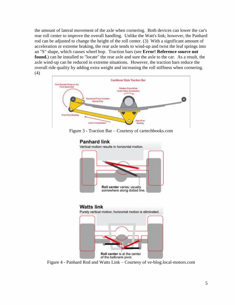
the amount of lateral movement of the axle when cornering. Both devices can lower the car's
rear roll center to improve the overall handling. Unlike the Watt's link; however, the Panhard
rod can be adjusted to change the height of the roll center. (3) With a significant amount of
acceleration or extreme braking, the rear axle tends to wind-up and twist the leaf springs into
an "S" shape, which causes wheel hop. Traction bars (see Error! Reference source not
found.) can be installed to "locate" the rear axle and sure the axle to the car. As a result, the
axle wind-up can be reduced in extreme situations. However, the traction bars reduce the
overall ride quality by adding extra weight and increasing the roll stiffness when cornering.
(4)
Figure 3 - Traction Bar – Courtesy of cartechbooks.com
Figure 4 - Panhard Rod and Watts Link – Courtesy of ve-blog.local-motors.com

6
AIR SUSPENSION Air suspension on a vehicle can be described as a shock absorber that is filled with
compressed air that is supplied by an onboard compressor. The compressor pumps air into
each individual shock. This replaces the conventional spring, which absorbs the energy
transferred from the road. Because each shock is individually filled with air, sensors can be
placed so that the suspension can self-adjust in various situations allowing for maximum
adaptability. (5) Whether the vehicle is cornering or traveling at high speed, air suspension
has the capability to adjust for maximum performance.
Figure 5 – Air Suspension System – Courtesy of Discoweb.org
Error! Reference source not found. illustrates the basic air suspension setup for a rear
axle. One of the benefits that this system offers is the ability to change the ride quality of the
vehicle, even while the car is in motion. (5) Adjusting the air suspension for ride quality can
allow the car to ride smoothly or roughly. Sporting and racing applications desire a stiff
suspension. With more advanced air systems the air springs can adjust for cornering, and
also keeps the car more level with the road than conventional springs. Thus, in some
situations the anti-roll bar can be deleted.
A contributing factor in high speed performance and fuel economy is wind resistance,
also known as drag. To minimize drag, the air suspension system utilizes its adaptability by

7
varying the ride height of the vehicle. In most cases, the underside of the vehicle is the
location in which the vehicle is least aerodynamic. Lowering the car allows for less air to
pass underneath the vehicle, thus reducing the less drag on the vehicle. The air suspension
lowers the vehicle at higher speeds when the vehicle encounters fewer large inconsistencies
in the road. In our application for the 1967 Ford Mustang, the front suspension will also
need to be converted to an air suspension for this particular feature to be utilized. (5)
Another benefit that air suspension has to offer is the ability to adapt to heavier loads
in the vehicle without negatively affecting the handling of the vehicle. This feature is known
as self-leveling, where the suspension increases the volume of air within a suitable camber
range. Self-leveling, with the proper sensors, can also adapt to uneven roads where one side
of the road is higher than the other. (5)
A drawback of the air suspension system is the overall weight compared to
conventional coil-over suspensions. Air suspensions are also very complex, requiring wiring
of the compressor and running air lines throughout the vehicle. Because the vehicle is
suspended by air pressure, if there is a leak in the system, the car becomes useless from the
lack of suspension. (5)
COILOVERS A coilover is a suspension component short for coil spring over shock absorber. They
consist of a shock absorber with a coil spring encircling it. The weight of the vehicle is
supported by the coilover. More accurately by the coil spring itself. The coil spring will
react to energy by extending and releasing the energy. If there wasn’t a shock absorber
present the spring would simply oscillate until it reaches equilibrium or until another force
was applied. This would result in very unsatisfactory conditions and an uncontrollable
vehicle. This is where the shock absorber is used for damping.
There are three kinds of coilovers; OEM-style spring-over-shock assemblies, slip-fit
coilovers and full-bodied coilovers. OEM-style spring-over shock assemblies are based off
of a conventional strut assembly surrounded by a coil spring. These are non-adjustable and
are made of a fixed-length (depending on the model). Slip-fit coilovers consist of a hollow,
threaded cylinder that sits on an existing shock perch shown below. (6)
Figure 6 – Adjustable Coilover – Courtesy of Super Street Online
These are able to be adjusted by compressing or decompressing the spring, thus
directly affecting the ride height of a vehicle. The two types mentioned earlier use existing
parts on a vehicle. A full-bodied coilover is an entire system. The full-bodied coilover will
8
be the focus due to not using any existing components.
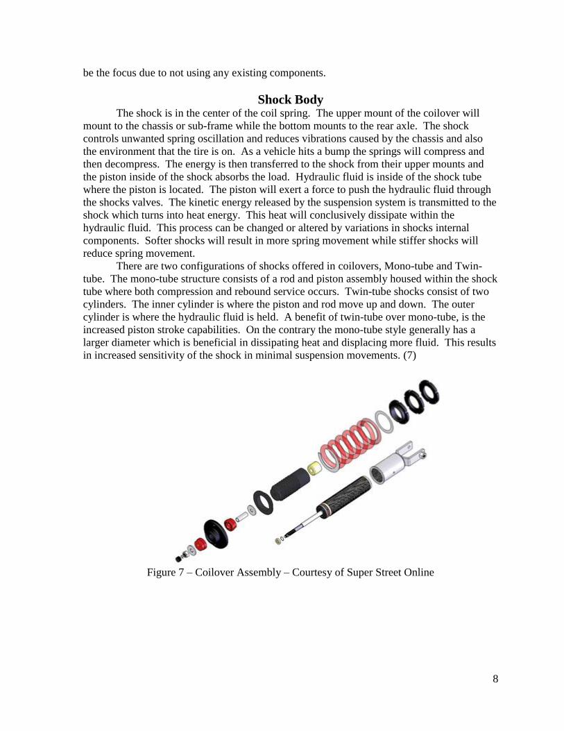
Shock Body The shock is in the center of the coil spring. The upper mount of the coilover will
mount to the chassis or sub-frame while the bottom mounts to the rear axle. The shock
controls unwanted spring oscillation and reduces vibrations caused by the chassis and also
the environment that the tire is on. As a vehicle hits a bump the springs will compress and
then decompress. The energy is then transferred to the shock from their upper mounts and
the piston inside of the shock absorbs the load. Hydraulic fluid is inside of the shock tube
where the piston is located. The piston will exert a force to push the hydraulic fluid through
the shocks valves. The kinetic energy released by the suspension system is transmitted to the
shock which turns into heat energy. This heat will conclusively dissipate within the
hydraulic fluid. This process can be changed or altered by variations in shocks internal
components. Softer shocks will result in more spring movement while stiffer shocks will
reduce spring movement.
There are two configurations of shocks offered in coilovers, Mono-tube and Twin-
tube. The mono-tube structure consists of a rod and piston assembly housed within the shock
tube where both compression and rebound service occurs. Twin-tube shocks consist of two
cylinders. The inner cylinder is where the piston and rod move up and down. The outer
cylinder is where the hydraulic fluid is held. A benefit of twin-tube over mono-tube, is the
increased piston stroke capabilities. On the contrary the mono-tube style generally has a
larger diameter which is beneficial in dissipating heat and displacing more fluid. This results
in increased sensitivity of the shock in minimal suspension movements. (7)
Figure 7 – Coilover Assembly – Courtesy of Super Street Online

9
Shock Travel Shock travel is the distance the shock is able to act before “bottoming out.” Bottoming
out is when the shock runs out of travel before emitting all of the acting energy to heat. (6) A
combination of shock travel and spring choice can prevent bottoming out.
Preload Preload is the amount of force applied to the springs. This can be determined by how
much the spring is compressed during static conditions. Adjusting the shock can allow more
load onto the spring. Adding preload can be beneficial in increasing tire contact while
cornering for example. Ride height is directly dependent on preload. (7) That is only the
case if the lower mounts for the coilover are non-adjustable. Adjustable lower mounts will
allow for preload adjustment while maintaining a consistent ride height (if that’s what you
want).
Conclusion Coilovers can be dialed in to best fit a specific application by a combination of position,
spring constant of the coil spring, and the shock absorber used. A correct combination of the
various styles can help create a sufficient suspension system.
THE WATT’S LINK When using a leaf spring style rear suspension the rear axle is able to move side to side.
The Watt’s link absorbs much of the lateral stress that the leaves were once receiving. This
allows the leaf springs to perform better by keeping the axle centered under the vehicle.
With the axle being centered it will not work against the front suspension. The Watt’s link
has the same response when corning left or right. (2) It’s also easily adjustable. The Watt’s
link is fairly complex, and due to its complexity it is the least common devise used in
centering a rear axle.
PANHARD A Panhard rod, or also commonly referred as a track bar, is another method of
centering the rear axle. This is more prevalent when compared to the Watt’s Link. A
Panhard rod is a lateral bar that runs from a frame of a vehicle to the axle. The goal is to
have the rod as close to horizontal as possible. (2) This allows the axle to stay more centered
under lateral load compared an angled Panhard bar. An angled Panhard bar may be
necessary depending on its application.
FOUR-LINK The overall main function of a four-link system is to maintain the proper location of a
rear axle under the vehicle. When a vehicle accelerates, makes a turn, or hits a bump the rear
axle will constantly want to move. There are two links, one on each side of the vehicle, two
upper links and two lower links. The lower links are used to keep the axle in place front to
back. The upper links keep the axle from rotating and keep the pinion angle as constant as
possible. Bret Voelkle of Air Ride Technologies was quoted saying “In a leaf-spring

10
suspension, the leaves perform two functions. First, they hold the rear axle in the car.
Secondly, while they are doing this, they also support the load of the vehicle. With a four-
link suspension, the functions of locating the rear axle and supporting the vehicle have been
separated. We like the four-link rear suspension because of its ability to properly locate the
rear axle no matter how soft we want to make the spring. With a leaf-spring rear suspension,
softening the spring rate can cause other problems such as side-to-side flex or axle wrap,
which is when the axle tries to twist the leaves out of the vehicle.” (2)
TRAINGULATED FOUR LINK A triangulated four-link uses the upper links to keep the rear axle centered under the
vehicle. This eliminates the need for a Panhard Bar or Watt’s Linkages. The upper links are
placed at angle compared to the lower links. Without the need for a Panhard Bar or Watt’s
Linkage, the area under the rear of the car becomes more open. This allows for other
modifications for example; re-routing exhaust, fuel cells, and batteries. When contemplating
a triangulated four-link one must consider “roll blind.” Roll blind is a non-linear resistance
to body roll. Body roll is the load transfer of a vehicle towards the outside of a turn. When a
vehicle is cornering the pivot points of all four links are resisting body roll. During this
resistance a side load is placed on the pivot points. Roll blind can cause snap oversteer or an
unanticipated transition from understeer to oversteer. (2) Methods to combat roll blind is by
using urethane bushings and or heim joints.
Figure 8 – Triangular 4-Link – Courtesy of Ridetech
PARALLEL FOUR-LINK A parallel four link functions very similarly. The upper and lower links are parallel to
another. The main difference of a parallel four-link compared to a triangulated is that a
Panhard bar or Watt’s link must be used. With the upper linkages being in parallel they are
unable to keep the rear axle centered under the vehicle. (8)

11
Figure 9 – Parallel 4-Link Utilizing Panhard – Courtesy of Ridetech
RESEARCH CONCLUSION
The conducted research reviewed many styles of rear suspension systems along with
their components. The research looked into the improvement of the original suspension
system. Improving the existing components includes upgrading the bushings, shock
absorbers, and spring leaves. Improvement of the original design also includes installing
traction bars and a Panhard bar or Watt’s link. These modifications would improve overall
handling, but from a marginal stand point. Improving the original design requires a lower
cost investment and involves an easier installation. However, enhancing the original
suspension system lacks in versatility, adjustability, and other key customer features.
The research directed itself in to the technology of air ride suspension
systems. While this type of suspension system provides many benefits towards handling and
adjustability, the components that would have to be implemented are not only very expensive
but also involve a complex installation process. The benefits that this system could supply
would be the reduction of body roll while cornering and automatic body leveling while under
various loads. These features would greatly improve the overall performance, but a
compromise had to be made with installation time and budget.
Through further research it was concluded that a 4-link coilover suspension meets the
desired customer features. The 4-link coilover suspension offers a lower cost alternative to
the air ride suspension, while also providing adjustability, greater performance, and greater
overall ride quality than the original design. The design of the suspension will be separated
into three major categories. The first category will include the selection of the coilover shock
absorber and the design of the multi-positioning mounting brackets. The second category
will include the selection of bushings and the design of the links and corresponding mounting
brackets. The final category will include the design of the sub-frame to properly support the
system.

1967 Mustang Rear Suspension Redesign Snyder
12
CALCULATIONS
Figure 10 - Link Force Calculations

1967 Mustang Rear Suspension Redesign Snyder
13
MANUFACTURING PROCESS The manufacturing process for the links would be strictly machining processes. The raw
round stock of 1.5” diameter 7075-T6 aluminum will be saw cut to rough in the finished
length. Once cut the links will then be machined to length and drilled and taped to achieve a
¾-16 thread which is 2.00” deep. As for the bracket that will attach the rod ends for the
links, they will be steel plate with a machined hole. Once all the parts are machined,
everything will be bolted together and tack welded into place on the car. After the parts have
been tacked welded, everything will be disassembled for welding. Welding the brackets in
the axle will required a pre heating process to allow for a sufficient weld.
Figure 11 - Model of 4-Link Assembly

1967 Mustang Rear Suspension Redesign Snyder
14
Figure 12 – Link Drilling
Figure 13 – Link Tapping

1967 Mustang Rear Suspension Redesign Snyder
15
TESTING
Figure 12 – Lower Link Finite Element Analysis
Figure 13 - Upper Link Finite Element Analysis
The loads for the links were calculated from the vehicle accelerating at 4 g’s. A car in
top-fuel drag will see around 6 g’s, we determined 4 g’s was sufficient because this particular
car will only see 1-2 g’s of acceleration. This was determined to be used so the customer
cannot be limited for acceleration by the aluminum links. The link in Figure is under
compression during acceleration and the link in Figure is under tension during acceleration.

1967 Mustang Rear Suspension Redesign Snyder
16
Testing the system will be determined by the amount of squat recorded by our testing
apparatus. A marker will be attached to the rear of the car, and will draw a black line on the
white testing apparatus as the car accelerates away. Because this particular car has an
automatic transmission, we will be able to accurately repeat this test. This will allow us to
hold the brake and reach a specified RPM and release the brake, resulting in an almost
identical launch of the car. Figure Figure shows the testing apparatus, which is 4’ x 4’ sheet
of plywood attached to 2”x 4” for bracing. The car will mark the flat side which is shown in
the figure.
Figure 14 – Model of Testing Apparatus

1967 Mustang Rear Suspension Redesign Snyder
17
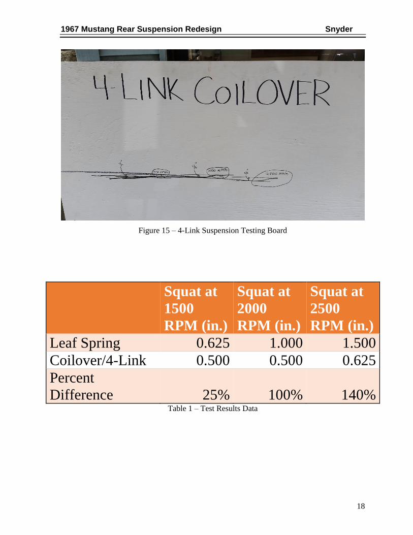
RESULTS The results from testing the system improved the amount of squat the car underwent at
all tested RPM’s. The addition of the links allowed for the force built up from holding the
accelerator down while holding the brake to be transferred into the links, instead of the leaf
springs. This allowed for a great reduction in axle wrap, this can be seen from the amount
the car rose while under stress from building up the RPMs. The leaf spring suspension rose
nearly three inches while the 4-link suspension didn’t raise at all during this step. Once the
brake was released, the leaf spring suspension system allowed the tires to spin, which was
caused by how the reduction of downforce from axle wrap, this can be seen on the data board
from the twenty four inches of acceleration before the car squats an inch and a half at 2500
rpm from the acceleration of the car finally gaining traction. The 4-link suspension allowed
for nearly immediate traction which allowed for the car to only squat 5/8th in. at 2500 RPM.
The 4-link board is much more difficult to read, because the car is accelerating much more
consistent do to the updated suspension system. The figures below are pictures of the testing
boards. The elimination of the leaf spring suspension and the addition of the 4-Link
suspension system, almost twenty pounds have been lost.
Figure 14 – Leaf Spring Testing Board
1967 Mustang Rear Suspension Redesign Snyder
18
Figure 15 – 4-Link Suspension Testing Board
Squat at
1500
RPM (in.)
Squat at
2000
RPM (in.)
Squat at
2500
RPM (in.)
Leaf Spring 0.625 1.000 1.500
Coilover/4-Link 0.500 0.500 0.625
Percent
Difference 25% 100% 140% Table 1 – Test Results Data

1967 Mustang Rear Suspension Redesign Snyder
19
Table 2 – Test Results Table
Leaf Spring Suspension
Description Quantity Weight (lbs.)
Total
(lbs.)
Leaf Spring Suspension 2 26.50 53.00
Shock Absorber Mount 2 13.00 26.00
Shock Absorber 2 3.00 6.00
Overall Total: 85.00
Table 3 – Leaf Spring Weight Table
0.000
0.200
0.400
0.600
0.800
1.000
1.200
1.400
1.600
Squat at 1500 RPM (in.) Squat at 2000 RPM (in.) Squat at 2500 RPM (in.)
Sq
uat
(in
.)
Motor Revolution Per Minute (RPM)
Squat of Suspension Types
Leaf Spring
Coilover/4-Link

1967 Mustang Rear Suspension Redesign Snyder
20
Triangulate 4-Link W/ Coilovers
Description Quantity Weight (lbs.)
Total
(lbs.)
Lower Links 2 4.00 8.00
Upper Links 2 2.90 5.80
Upper Links-Brackets 2 0.25 0.50
Lower Coilover Brackets 2 10.00 20.00
Coilover 2 9.00 18.00
Coilover Spacer 2 0.25 0.50
Chassisworks Offset Bracket 2 0.50 1.00
Subframe 1 7.75 7.75
Additional Hardware 1 4.00 4.00
Overall
Total: 65.55
Table 4 – Triangulated 4-Link Weight Table
CONCLUSION With the elimination of the leaf spring suspension and the addition of the 4-link
suspension system we were able to reduce the weight of the vehicle by nearly twenty pounds
from eliminating unnecessarily heavy materials. Also, we were able to achieve a much more
consistent launch of the vehicle by reducing axle wrap and reducing the squat of the vehicle.
This is beneficial for the consumer to fine tune other components of the car for their specific
application. Allowing for easy coilover angle and ride height adjustability allows the
consumer to achieve their desired look of the vehicle while having multiple racing types in
one package. The location of the mounting bolts will allow the consumer to switch between
a drag setup to a road course setup in about twenty minutes, also being able to adjust ride
height for varying tire sizes. The maximum test improvement of this system was recorded at
140% decrease in squat at 2500 RPM. The general trend of the data would indicate that we
would decrease the squat even more at greater RPMs.

1967 Mustang Rear Suspension Redesign Snyder
21
WORKS CITED 1. Date, Colin. Original Mustang 1967-1970: The Restorer's Guide. St. Paul MN :
Motorbooks, 2006.
2. Rupp, Steven. Terra Firma - Rear Suspension Guide - Popular Hot Rodding. Hot Rod
Network. [Online] February 27, 2006. [Cited: September 20, 2015.]
http://www.hotrod.com/how-to/chassis-suspension/0604-rear-suspension-guide/.
3. Pisani, Mike. What's a Watts Link anways? Local Motors: Engineering. [Online] June 16,
2009. [Cited: September 20, 2015.] http://ve-blog.local-motors.com/2009/06/whats-watts-
link-anyways_16.html.
4. CarTech Books. Muscle Car Handling Upgrades: Rear Suspension System. Car Tech
Auto Books and Manuals. [Online] April 11, 2015. [Cited: September 20, 2015.]
http://www.cartechbooks.com/techtips/muscle-car-handling-upgrades-rear-suspension-
system.
5. Air Suspension. Why High End? [Online] 2010. [Cited: September 20, 2015.]
http://www.whyhighend.com/air-suspension.html.
6. Bonk, Aaron. Super Street Online. The Enthusiast Network. [Online] April 9, 2013.
[Cited: September 20, 2015.] http://www.superstreetonline.com/features/news/303hp-
2015-mitsubishi-lancer-evolution-final-edition-unveiled/.
7. Ansell, Bill. The BillaVista Tech Garage. Pirate 4x4. [Online] 2008. [Cited: October 7,
2015.] http://www.pirate4x4.com/tech/billavista/coilovers/Part_1/.
8. RideTech. Air4Link Tech: Whats the difference between a triangulated 4 link and a
parallel 4 link? Ride Tech Air Technologies. [Online] [Cited: October 7, 2015.]
http://www.ridetech.com/info/air4link-tech/.
9. Engineering Explained: How Suspension Works And Upgrading To Coilovers. Car
Throttle. [Online] July 1, 2015. [Cited: September 20, 2015.]
https://www.carthrottle.com/me/.
10. Super Pro Poly. Super Pro Suspension Parts. [Online] 2014. [Cited: September 20,
2015.]
http://www.superpropoly.de/index.php?language=en&cPath=7_101_473&axle=F.

22
APPENDIX A – COMPILED CUSTOMER SURVEY
CUSTOMER SURVEY Redesign of a 1967 Ford Mustang Rear Suspension
The Ford Mustang has been a popular choice for car enthusiasts and collectors alike
throughout the cars history. This design will be focused on implementing modern technology
on a classic vehicle. The rear suspension of a 1967 Mustang uses leaf springs and shock
absorbers. This design entails the usage of coil-overs and a 4-link suspension system to
enhance overall driving characteristics and performance.
How important is each feature of the proposed rear suspension design?
Please circle the appropriate answer. 1=Low Importance 5=High
Importance
Initial Investment Cost 1 2(1) 3(1) 4 5(1) N/A
Complexity of Installation 1 2 3(1) 4(2) 5 N/A
Weight 1 2 3(1) 4(1) 5(1) N/A
Serviceability 1 2 3(2) 4(1) 5 N/A
Adjustability 1 2 3 4(1) 5(2) N/A
Ride Quality 1 2 3 4(2) 5(1) N/A
Material 1 2(2) 3(1) 4 5 N/A
How adequate is the current leaf spring and shock absorber suspension system?
Please circle the appropriate answer. 1=Very Unsatisfied 5=Very Satisfied
Initial Investment Cost 1 2(2) 3 4 5 N/A(1)
Complexity of Installation 1 2(1) 3 4(1) 5 N/A(1)
Weight 1 2(1) 3(1) 4 5(1) N/A
Serviceability 1 2(1) 3(2) 4 5 N/A
Adjustability 1(1) 2(1) 3 4 5 N/A(1)
Ride Quality 1(1) 2(1) 3 4(1) 5 N/A
Material 1 2(2) 3 4 5 N/A(1)
How much would you be willing to spend on this technology?
$1,000-$1,500 $1,500-$2,000 (2) $2,000-2,500 $2,500-$3,000 $3,000+ (1)

23
APPENDIX B – QUALITY FUNCTION DEPLOYMENT (QFD)
Engineering Characteristics
Imp
ort
ance W
eig
ht
Ad
just
ab
le
linka
ge
s
Mu
lti-P
osi
tio
n
Mo
un
ts
Inv
asi
ve
Inst
alla
tio
n
Hig
h G
rad
e
Ha
rdw
are
Sp
rin
g C
on
sta
nt
Da
mp
en
ing
Lig
htw
eig
ht
ma
teria
ls
Sta
nd
ard
Siz
e
Eq
uip
.
Ro
un
de
d S
urf
ac
es
Cu
sto
me
r Sa
tisf
ac
tio
n
Ra
tin
g
(0.0
0 -
1.0
0)
Customer Requirements
1 2 3 4 5 6 7 8 9 CP
1
Initial
Investment
Cost
13% 3 9 3 3 9 3 0.40
2 Complexity of
Install 14% 1 1 9 1 3 0.60
3 Weight 16% 1 3 1 1 9 1 1 0.67
4 Serviceability 13% 1 1 0.53
5 Adjustability 18% 9 9 3 1 3 0.30
6 Ride Quality 17% 3 3 9 9 3 0.47
7 Material 9% 3 9 3 9 1 0.40
2.27 3.09 1.80 2.64 2.35 2.76 4.06 0.80 0.55
Table 5 - QFD

24
APPENDIX C – TIMELINE
Figure 16 – Timeline of Project
Mu
sta
ng
S
usp
en
sio
n
TIM
EL
INE
PR
OJE
CT
DE
TA
ILS
DA
TE
MIL
ES
TO
NE
No
tes
10/1
2/20
15P
roje
ct S
tart
11/2
0/20
153D
Mod
elin
gE
xist
ing
Fra
me,
Sub
-Fra
me,
Lin
ks,
Coi
love
rs,
and
Bra
cket
s
12/1
2/20
15D
esig
n C
alcu
latio
nsC
alcu
late
Lin
k Le
ngth
s an
d A
ngle
s
12/1
5/20
15B
ill o
f Mat
eria
ls
12/1
7/20
15D
raw
ings
2/9/
2016
Rep
orts
Due
2/12
/201
6O
rder
Mat
eria
ls
3/2/
2016
Fab
ricat
ion/
Mac
hini
ng
3/9/
2016
Ass
embl
y
3/30
/201
6Te
stin
g
4/10
/201
6M
odifi
catio
ns
4/15
/201
6F
inal
Tes
ting/
Fin
al M
odifi
catio
ns
4/20
/201
6P
roje
ct E
nd -
Tec
h E
xpo
4/25
/201
6P
rese
ntat
ion
to F
acul
ty
PR
OJE
CT
ST
AR
T
3D
MO
DE
LIN
G
DE
SIG
N C
AL
CU
LA
TIO
NS
BIL
L O
F M
AT
ER
IAL
S
DR
AW
ING
S
RE
PO
RT
S D
UE
OR
DE
R M
AT
ER
IAL
SFA
BR
ICA
TIO
N/M
AC
HIN
ING
AS
SE
MB
LY
TE
ST
ING M
OD
IFIC
AT
ION
S
FIN
AL
TE
ST
ING
/FIN
AL
M
OD
IFIC
AT
ION
S
PR
OJE
CT
EN
D -
TE
CH
EX
PO
PR
ES
EN
TA
TIO
N T
O F
AC
UL
TY
12 O
ct12
Nov
12 D
ec12
Jan
12 F
eb12
Mar
12 A
pr

25
APPENDIX D – BUDGET
Component Supplier/Vendor Estimated Cost Actual Cost 2x Coilovers Ridetech $ 850.00 $ 665.00
Coilover
Dropdown Ridetech $ 50.00 $ 60.00
2x Lower Coilover
Offset Mount Chassisworks $ 120.00 $ 93.00
Material Raw Material $ 400.00 $ 236.50
Hardware McMaster Carr $ 280.00 $ 291.76
Machining In-House $ - $ -
Welding In-House $ 20.00 $ -
Bending In-House $ - $ -
Painting In-House $ 50.00 $ 26.90
Car Transport U-Haul $ 80.00 $ 67.36
TOTAL $ 1,850.00 $ 1,440.52 Table 6 - Budget

26
APPENDIX E – DETAIL DRAWINGS
Figure 17 – Upper Link Drawing
Figure 18 – Lower Link Drawing

27
Figure 19 – Upper Axle Link Mount – 1 Drawing
Figure 20 – Upper Axle Link Mount – 2 Drawing