Real-Time Processing of 3D-TOF Data in Machine Vision Applications
22
4 Real-Time Processing of 3D-TOF Data in Machine Vision Applications Stephan Hussmann, Torsten Edeler and Alexander Hermanski Institute for Machine Vision Technology (Ma.Vi.Tec), West Coast University of Applied Sciences Germany 1. Introduction In machine vision applications, Time-of-Flight (TOF) sensors like the Photonic Mixer Devices (PMD Technologies [PMD], 2011) became considerable alternatives to common 3D sensing devices. Because of the enormous progress in TOF-vision systems, nowadays 3D matrix cameras can be used for many applications such as robotic, automotive, industrial, medical and multimedia applications. Due to the increasing demand of safety requirements in the automotive industry it can be assumed that the TOF-camera market will grow and the unit price of these systems in the mass production will drop down to ca. 100 € (Hussmann & Hess, 2006). Many 3-D sensing techniques have been developed in the past decades. A good review can be found in (Jarvis, 1983). 3-D sensing methods can be divided into several categories: 1. Shape-from Techniques: These monocular approaches recover relative depth from texture, from shading, from contours, from motion, etc.; resulting in surface orientations with respect to a viewer-centered coordinate system (Hu & Stockman, 1989). These techniques must deal with correspondence problems. Furthermore problems arise due to the uncertainty of the position at which each image is taken and due to dynamic changes that may occur in the time between two images. 2. Stereo: This method simulates the two eyes of a human. It uses multiple visual sensors (two cameras, for example) to estimate stereo disparity and then recover depth (Hu & Stockman, 1989). Stereo cameras introduce physical restrictions due to the need for camera separation. Further, stereo cameras depend on texture matching from both camera images for range estimation. This produces a rather sparse and unevenly distributed data set. Due to the allocation problem dynamic tracking of objects is not an easy task (Hussmann & Liepert, 2009). 3. Structured Light: In illuminating the scene, natural ambient light is replaced by an artificial light source, which can be of any structure (pattern) that is convenient for the task. Using structured light by itself is not an independent approach to 3-D sensing; the underlying means is still a monocular (shape-from) or binocular (stereo) method, but under different illumination conditions and hence facing rephrased problems. If a single light beam or a single light plane is used as the light source, the underlying method is direct sensing through triangulation. If a uniform grid of light is the light source, the underlying method is stereo and analysis of textures and contours. The www.intechopen.com
Transcript of Real-Time Processing of 3D-TOF Data in Machine Vision Applications

4
Real-Time Processing of 3D-TOF Data in Machine Vision Applications
Stephan Hussmann, Torsten Edeler and Alexander Hermanski Institute for Machine Vision Technology (Ma.Vi.Tec),
West Coast University of Applied Sciences Germany
1. Introduction
In machine vision applications, Time-of-Flight (TOF) sensors like the Photonic Mixer Devices (PMD Technologies [PMD], 2011) became considerable alternatives to common 3D sensing devices. Because of the enormous progress in TOF-vision systems, nowadays 3D matrix cameras can be used for many applications such as robotic, automotive, industrial, medical and multimedia applications. Due to the increasing demand of safety requirements in the automotive industry it can be assumed that the TOF-camera market will grow and the unit price of these systems in the mass production will drop down to ca. 100 € (Hussmann & Hess, 2006).
Many 3-D sensing techniques have been developed in the past decades. A good review can be found in (Jarvis, 1983). 3-D sensing methods can be divided into several categories:
1. Shape-from Techniques: These monocular approaches recover relative depth from texture, from shading, from contours, from motion, etc.; resulting in surface orientations with respect to a viewer-centered coordinate system (Hu & Stockman, 1989). These techniques must deal with correspondence problems. Furthermore problems arise due to the uncertainty of the position at which each image is taken and due to dynamic changes that may occur in the time between two images.
2. Stereo: This method simulates the two eyes of a human. It uses multiple visual sensors (two cameras, for example) to estimate stereo disparity and then recover depth (Hu & Stockman, 1989). Stereo cameras introduce physical restrictions due to the need for camera separation. Further, stereo cameras depend on texture matching from both camera images for range estimation. This produces a rather sparse and unevenly distributed data set. Due to the allocation problem dynamic tracking of objects is not an easy task (Hussmann & Liepert, 2009).
3. Structured Light: In illuminating the scene, natural ambient light is replaced by an artificial light source, which can be of any structure (pattern) that is convenient for the task. Using structured light by itself is not an independent approach to 3-D sensing; the underlying means is still a monocular (shape-from) or binocular (stereo) method, but under different illumination conditions and hence facing rephrased problems. If a single light beam or a single light plane is used as the light source, the underlying method is direct sensing through triangulation. If a uniform grid of light is the light source, the underlying method is stereo and analysis of textures and contours. The
www.intechopen.com

Machine Vision – Applications and Systems
74
major advantage of using structured light over ambient light is that features in the images are better defined. Image features are easier to detect; their relationships are more regular (parallel, equi-spaced, etc.) following the property of the generating pattern of the light source; and they prominently reveal the surface geometry that humans can readily use to interpret the scene (Hu & Stockman, 1989).
4. Direct Sensing (time-of-flight): One representative of this approach is a laser range finder, which can sense the depth to any surface point in its field of view. Laser range finders are often used for navigation tasks (Nuechter et al., 2003). The major disadvantage of these systems is the use of mechanical components and that they do not deliver 2D intensity images and range data at the same time. Another representative are TOF cameras (Blanc et al., 2004 ; Schwarte et al., 1997), which combine the advantage of active sensors and camera based approaches as they provide a 2D image of intensity and exact distance values in real-time. They do require a synchronized light source. Compared to Shape-from Techniques and Stereo TOF cameras can deal with prominent parts of rooms like walls, floors, and ceilings even if they are not structured. In addition to the 3D point cloud, contour and flow detection in the image plane yields motion information that can be used for e.g. car or person tracking (Hussmann et al., 2008). Structured light applications can have a higher measurement accuracy as TOF-cameras, however the measurement range is then limited.
Inspection task in machine vision applications e.g. quality control of bulk materials are very complex due to their real-time requirements. New accurate and fast algorithms for 3D object recognition and classification are needed as the inspection time is always decreasing. As now commercial 3D-TOF cameras are available at a reasonable price the number of machine vision applications using this technology is expected to increase significantly. Hence in this book chapter the use of 3D-TOF cameras for machine vision applications is investigated.
The state of the art is to use a four-phase shift algorithm for TOF cameras to correctly determine the range value (Blanc et al., 2004; Lange & Seitz, 2001; Ringbeck & Hagebeuker, 2007). The optical signal is sampled four times per period at equidistant intervals. The corresponding sampling points permit unique determination of all relevant parameters of the incoming optical echo’s waveform. The sample points are not acquired during only a single period but summed over several hundreds or thousands of periods, which considerably increases the signal-to-noise ratio and hence, finally, the accuracy of the measurement. Due to acquisition of the four subsequent phase images, fast object motion leads to distance uncertainties in situations where corresponding phase images do not properly align with respect to object points.
In (Hussmann & Edeler, 2010) we presented a pseudo-four-phase-shift algorithm for 3D-TOF photonic mixer device (PMD) cameras, which only has to capture two phase images and thereby doubles the frame rate. Hence distance uncertainties by fast moving objects will be reduced. In (Hussmann et al., 2011a) we presented a simple motion compensation algorithm for constant lateral motion such as measure objects on a conveyor belt, which can be processed with the maximum frame rate of currently available commercial TOF cameras. However this algorithm was based on the state of the art 4-phase shift algorithm.
In this book chapter we will combine the two proposed algorithms and evaluate their performance in comparison to the state-of-the-art algorithm. The book chapter is structured as follows. In section 2 we derive the basics of PMD TOF vision systems and subsequently
www.intechopen.com
Real-Time Processing of 3D-TOF Data in Machine Vision Applications
75
present algorithms used for real-time processing of PMD TOF data. In section 3 experiments are conducted to investigate the real-time performance of the proposed algorithm for machine vision applications. Concluding remarks will summarize the chapter.
2. Real-time processing of PMD TOF data
2.1 Operating principle of PMD TOF sensors
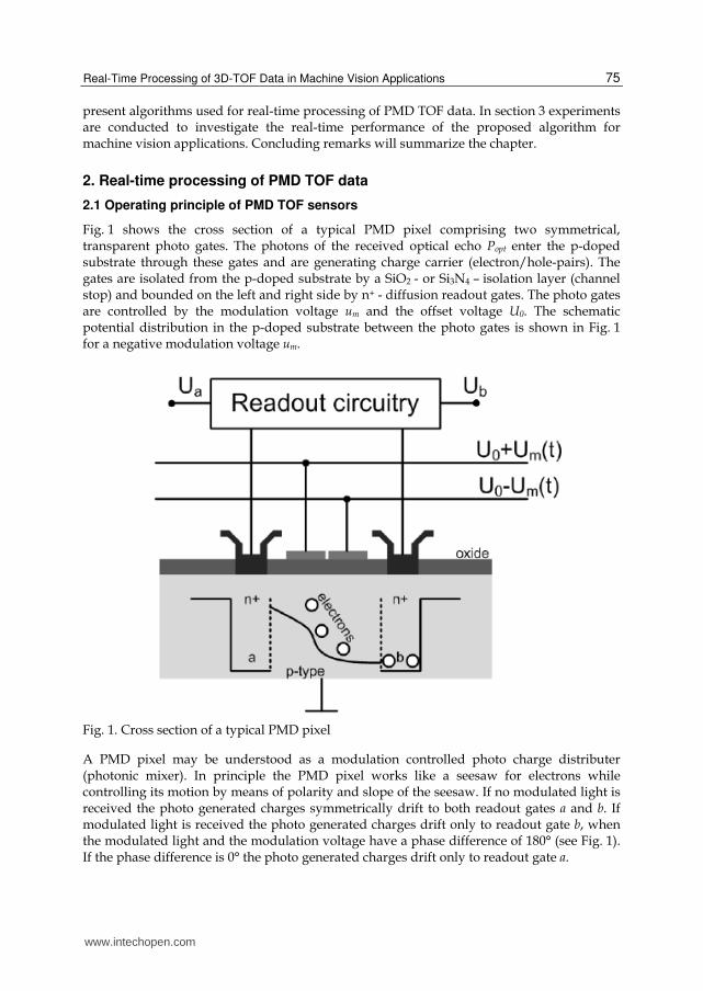
Fig. 1 shows the cross section of a typical PMD pixel comprising two symmetrical, transparent photo gates. The photons of the received optical echo Popt enter the p-doped substrate through these gates and are generating charge carrier (electron/hole-pairs). The gates are isolated from the p-doped substrate by a SiO2 - or Si3N4 – isolation layer (channel stop) and bounded on the left and right side by n+ - diffusion readout gates. The photo gates are controlled by the modulation voltage um and the offset voltage U0. The schematic potential distribution in the p-doped substrate between the photo gates is shown in Fig. 1 for a negative modulation voltage um.
Fig. 1. Cross section of a typical PMD pixel
A PMD pixel may be understood as a modulation controlled photo charge distributer (photonic mixer). In principle the PMD pixel works like a seesaw for electrons while controlling its motion by means of polarity and slope of the seesaw. If no modulated light is received the photo generated charges symmetrically drift to both readout gates a and b. If modulated light is received the photo generated charges drift only to readout gate b, when the modulated light and the modulation voltage have a phase difference of 180° (see Fig. 1). If the phase difference is 0° the photo generated charges drift only to readout gate a.
www.intechopen.com

Machine Vision – Applications and Systems
76
State of the art is to use continuous wave (CW) modulation with square waves for TOF cameras with a typical modulation frequency of 20 MHz (Hussmann et al., 2008). Hence the modulation voltages can be easily generated digitally with a high accuracy and stability using programmable logic devices (PLDs) such as complex programmable logic devices (CPLD) or field programmable gate arrays (FPGA). For the illumination source infrared (IR) - light emitting diodes (LEDs) are used. The low-pass characteristic of the IR-LEDs leads to an attenuation of the square waves’ harmonics for larger frequencies. This results in an optical output that gradually looks sinusoidal for frequencies larger than 5-10 MHz (see Fig. 2). This has to be taken into account if CW modulation with square waves is used.
Fig. 2. Correlation process between the received optical echo Popt and the modulation voltage um for a single modulation period
The readout gates a and b are each connected to an integration capacitor. Hence the corresponding voltages Ua and Ub can be expressed as a correlation function between the optical echo Popt(t-TL) and the modulation voltage um(t) over the integration time Tint. Fig. 2 illustrates the correlation process for one single modulation period T for the two signals Popt(t-TL) and um(t). The modulation voltage um(t) and the optical echo Popt(t-TL) are defined as follows:
1, for 0 t-N T T/2
( )0, for T/2 t-N T Tmu t
, N = 0,1,2… (1)
0( ) cos( )opt L LP t T a t T B (2)
TL is the ‘time-of-flight’ time for the light (camera-object-camera), B is the received average incident light (background light and DC component of the modulated light source) and a0 is the amplitude of the received modulated light. Ua and Ub are then proportional to the areas Aa and Ab as shown in Fig. 2. If the complete integration time Tint (corresponds to several hundreds or thousands of periods) has taken into account, Ua and Ub can be written as:
int
int 0 int
0
( ) ( ) ( ) sin( ) ( )2
T
a L opt L m L a L
T T a TT BU T K P t T u t dt K T K A T
T T
(3)
www.intechopen.com
Real-Time Processing of 3D-TOF Data in Machine Vision Applications
77
and
int
int 0 int
0
( ) ( ) ( /2) sin( ) ( )2
T
b L opt L m L b L
T T a TT BU T K P t T u t T dt K T K A T
T T
(4)
The conversion gain K converts the received optical energy into a voltage. The integration time Tint does not have to be necessarily a multiple of the single period time T as the number of periods integrated over the integration time is in the range of hundreds to thousands. Looking at Fig. 2 it can be noticed that Ua and Ub are always a positive voltage. To remove
the influence of the background light B the difference of Uab has to be determined:
int( ) ( ) ( )ab L a b a L b L
TU T U U K A T A T
T (5)
The autocorrelation function Uab corresponds to the distance value of a PMD pixel. The sum of Ua and Ub corresponds to all received and converted photons. Hence this sum is equivalent to the grey level value of standard CCD/CMOS video cameras (amplitude image):
BdtTtPKAAT
TKUUU
T
Loptbabaab int
0
int )()( (6)
It has to be mentioned that in this book chapter only infrared light is used as an IR-filter is
mounted on top of the sensor chip. Using an IR-filter reduces the effects of the background
illumination B on the distance resolution. Hence the amplitude image in this book chapter
could be also called “infrared amplitude image”. However without the IR-filter the TOF
camera would behave like a standard 2D-camera and therefore we still use the word
“amplitude image”.
Equation (5) and (6) demonstrate the advantage of the PMD technology compared to other
3-D sensing techniques. The PMD pixel is a TOF vision system with inherent suppression of
uncorrelated light signals such as sun light or other modulated light disturbances (neon
tubes, high frequency illumination modules etc.). More advantages of a PMD TOF vision
system are the acquisition of the amplitude value and range data in each pixel without high
computational cost and any moving components as well as the monocular setup.
2.2 State-of-the-art range image calculation using 4-phase shift algorithm
As mention in the last section the range value corresponds to Uab. The amplitude of the received optical echo Popt varies with the measure object reflectivity coefficient and the
distance. Hence the amplitude of the output voltage Uab is also affected by these changes. To
overcome the amplitude dependency of the output voltage of Uab state of the art is to use a 4-phase shift algorithm (Blanc et al., 2004; Lange & Seitz, 2001; Ringbeck & Hagebeuker, 2007). In
(Hussmann & Liepert, 2009) the following equation to calculate the phase difference 0 without any dependency on the received optical echo’s amplitude is derived:
0
(270 ) (90 )arctan
(0 ) (180 )ab ab
ab ab
U U
U U (7)
www.intechopen.com

Machine Vision – Applications and Systems
78
The range value R can now be calculated by taken into account the modulation frequency
fmod and the physical constant for the speed of light c (3108 m/s). N represents the ambiguity
in range estimation when 0 > N 360°. For example if a modulation frequency of 20 MHz is used the ambiguity range is 7,5 m. If the distance to an object is now 9 m, N = 1 and the distance measured by the camera is 1.5 m.
0
mod
0,1,2,3...2 360
cR N with N
f
(8)
2.3 Real-time range image calculation using pseudo 4-phase shift algorithm
Looking at equation (3) and (4) it can be noticed that Ua and Ub have a phase difference of 180° (T/2) to each other:
int 0 int 0( ) sin( ) sin( ) ( )2 2 2 2
a L L L b L
T T a T T aT T T B T BU T K T K T U T
T T
(9)
Hence the output voltage Uab can be expressed as:
( ) ( ) ( ) ( ) ( / 2)ab L a L b L a L a LU T U T U T U T U T T (10)
Equation (10) shows that a PMD pixel delivers two phase values (Ua(TL) and Ua(TL+T/2)) at one image capture. Therefore equation (7) can be simplified to:
0
(90 )arctan
(0 )ab
ab
U
U (11)
The range value R can now be calculated by using equation (8). Equation (11) demonstrates the advantage of the pseudo 4-phase shift algorithm. Only two image
captures instead of four are required to calculate the phase difference 0. Hence the frame rate of PMD TOF sensors is doubled without changing the integration time Tint. A typical frame rate of TOF PMD cameras is 50 Hz. The pseudo 4-phase shift algorithm increases this frame rate to 100 Hz and hence is well suited for real-time machine vision applications. A more detailed description of the pseudo 4-phase shift algorithm can be found in (Hussmann & Edeler, 2010).
2.4 Real-time arctangent calculation using a reconfigurable processor system
The most time critical operation of the phase difference 0 calculation is the arctangent
function (see equation (7) and equation (11)). As the arctangent function is called for each
individual pixel to determine the range value, the processing time increases with the
number of present pixels. The hardware algorithm proposed in (Hussmann et al., 2011b) to
calculate the arctangent value for 3D-TOF PMD cameras in real-time is realized as a custom
functional unit on the reconfigurable functional unit (RFU) of a reconfigurable processor in a
FPGA. This algorithm replaces the state-of-the-art CORDIC arctangent function commonly
used in microcontrollers. This significantly decreases the processing time to determine the
range image of the 3D vision system.
www.intechopen.com

Real-Time Processing of 3D-TOF Data in Machine Vision Applications
79
As the arctangent function is symmetrical only the angles from zero to ninety degree have to be calculated. A further reduction of the angle range down to 45° can be achieved by taken into account the following:
00 0
00
00 0
0
arctan , for
90 arctan , for
yy x
x
xy x
y
(12)
With a desired range resolution of 1 mm (equivalent to an angle resolution of 0.048°) and
an angle range of 45°, a LUT with 2048 elements is needed. As shown in table 1 this LUT
is filled with the distance values of the according phase angles. As can be seen in table 1
the distance resolution between each LUT entry is smaller than 1 millimeter. Furthermore
it can be seen that at the end of the LUT the distance resolution is better as at the start of
the LUT.
i tan(angle) = i / 2048 angle in degree distance in mm
0 0 0 0
1 0.000488 0.027976 0.6
2 0.000977 0.055953 1.2
3 0.001465 0.083929 1.7
4 0.001953 0.111906 2.3
5 0.002441 0.139882 2.9
6 0.002930 0.167858 3.5
7 0.003418 0.195834 4.1
8 0.003906 0.223811 4.7
9 0.004395 0.251786 5.2
…
2042 0.997070 44.915948 935.7
2043 0.997559 44.929973 936.0
2044 0.998047 44.943992 936.3
2045 0.998535 44.958005 936.6
2046 0.999023 44.972010 936.9
2047 0.999512 44.986008 937.2
Table 1. Lookup table of the hardware algorithm
Looking at equation (12) a comparator, a hardware divider, a subtraction device and a LUT is needed to determine the distance value. The comparator checks if y0 > x0, the hardware divider calculates y0 / x0 or x0 / y0 depending on the comparator result, the division result is used as index for the LUT and finally the LUT delivers, depending on the comparator result,
www.intechopen.com

Machine Vision – Applications and Systems
80
the distance value directly or this value has to be subtracted from the distance value 1.875 m (equivalent to 90°).
The hardware algorithm and the state-of-the-art CORDIC algorithm is implemented into a FPGA (Altera Stratix EP1S10F780C6) using a clock frequency of 50 MHz. Therefore the CORDIC algorithm takes 340 ns and the proposed hardware algorithm 160 ns respectively for a standard arctangent calculation. Compared to the execution time of 800 µs for the arctangent C-function atan2() from the “math.h” library on the NIOS II processor, a speed-up factor of 2,353 for the CORDIC algorithm and 5,000 for the proposed hardware algorithm is achieved. Hence the total processing time of one range image of a TOF camera with 204 x 204 pixels (PMD[vision]® CamCube 2.0) takes for the CORDIC algorithm 14.15 ms and for the proposed hardware algorithm 6.66 ms respectively.
The maximum frame rate of the used commercial camera (PMD[vision]® CamCube 2.0) is 25
fps, which corresponds to a capture time of 40 ms per image. Using the proposed algorithm
with the total processing time for the arctangent function of 6.66 ms leaves enough time to
process the range calculation in real-time. To our knowledge there is no other hardware
algorithm with the same performance. The proposed approach will significantly reduce the
system costs of TOF cameras as state-of-the-art is to use high performance microcontroller in
combination with a FPGA. This is an important achievement as the current 3D TOF cameras
are too expensive for common machine vision applications. A more detailed description of the
hardware algorithm can be found in (Hussmann et al., 2011b).
2.5 Real-time motion artifact compensation
Distance uncertainties typically occur where objects or the camera itself move while the
consecutive phase images are taken. They arise from unmatched phase values during the
demodulation process. The faster the objects move or the higher the integration time the
higher are the distance uncertainties. In (Hussmann et al., 2011a) a compensation algorithm
for constant lateral motion is proposed as this is a typical motion in machine vision
applications. One industrial example is 3D dimension measurement of objects on a conveyor
belt (luggage handling systems, quality control of food or beverages etc.).
The lateral motion of objects on a conveyor belt has to be corrected in only one direction
(moving direction of the conveyor belt). This can be done by subtracting the captured
amplitude images Uab(0°), Uab(90°), Uab(180°) and Uab(270°), and subsequent
thresholding using a fixed threshold s to get the binary image B1-B3:
(0 ) ( 90 ) , with n 1,2,3n ab abB U U n s (13)
Fig. 3 shows typical binary images of an object moving on a conveyor belt. It can be seen
that the width of the white area increases linear with the capture time. To compensate the
motion the width of the area has to be determined and the amplitude images have to be
moved accordingly before the distance image is calculated. The proposed method is
computational not expensive and can be easily integrated into an FPGA as shown in
(Hussmann et al., 2011a). Hence the motion compensation can be realized in real-time. It has
to be noticed that the sensor must be calibrated to make sure that every pixel has a uniform
behaviour when exposed with the active light source of the TOF camera (multiplicative
www.intechopen.com

Real-Time Processing of 3D-TOF Data in Machine Vision Applications
81
shading calibration). A more detailed description of the motion artefact compensation
algorithm and the calibration method can be found in (Hussmann et al., 2011a).
Fig. 3. Binarized difference images of the application in section 3
(a) Binary image of difference image Uab(0°)-Uab(90°)
(b) Binary image of difference image Uab(0°)-Uab(180°)
(c) Binary image of difference image Uab(0°)-Uab(270°)
3. Experiments
3.1 Experimental setup
In Fig. 4 the laboratory setup is shown. A measure object (10 cm x 10 cm x 12 cm) is placed on a conveyor belt, which runs at a speed of 1 m / s. A PMD TOF camera (PMD[vision]® CamCube 2.0) with 204 x 204 pixels is placed 103 cm above the conveyor belt. The raw data
(Ua and Ub) of the PMD camera for the four different phases ( = 0°, = 90°, = 180° and = 270°) are captured and the proposed motion compensation algorithm in (Hussmann et al., 2011a) combined with the pseudo-four-phase-shift algorithm proposed in (Hussmann & Edeler, 2010) is investigated offline using Matlab.
motion direction
(a) (b)
(c)
www.intechopen.com

Machine Vision – Applications and Systems
82
Fig. 4. Laboratory setup
PMD-TOF camera
measure object
conveyor belt
www.intechopen.com

Real-Time Processing of 3D-TOF Data in Machine Vision Applications
83
3.2 Experimental results
Fig. 5 shows the amplitude images of the four different phases. The amplitude image is calculated using equation (6). The displacement of the measure object is difficult to notice hence the subtraction results between the different amplitude images are shown in Fig. 6.
The displacement of the object during the acquisition of the four phase images can be clearly seen in Fig. 6. After thresholding and moving of the phase images as proposed in section 2.5, the corrected distance image can be calculated.
Fig. 5. Amplitude images of the four different phases:
(a) Amplitude image of Uab(0°) (“ground truth”)
(b) Displaced amplitude image of Uab(90°)
(c) Displaced amplitude image of Uab(180°)
(d) Displaced amplitude image of Uab(270°)
Fig. 7 – Fig. 10 illustrate the influence of the calibration method and the motion artefact
compensation algorithm proposed in (Hussmann et al., 2011a) on the distance image using
the state-of-the-art 4-phase shift algorithm and the pseudo 4-phase shift algorithm proposed
in (Hussmann & Edeler, 2010) respectively. Fig. 7 shows the distance image without motion
(a) (b)
(c) (d)
www.intechopen.com

Machine Vision – Applications and Systems
84
compensation using the state-of-the-art 4-phase shift algorithm. It can be seen that the
distance at the object edges are not calculated correctly (area 1 and area 3) and that the
standard deviation is larger than in the other areas (see table 2). Furthermore it can be
noticed that the distance image in Fig. 7 (a) is noisier than in Fig. 7 (b) due to the calibration
method proposed in (Hussmann et al., 2011a).
Fig. 6. Subtraction results of the amplitude images:
(a) Amplitude image of Uab(0°) (“ground truth”)
(b) Difference image Uab(0°)-Uab(90°)
(c) Difference image Uab(0°)-Uab(180°)
(d) Difference image Uab(0°)-Uab(270°)
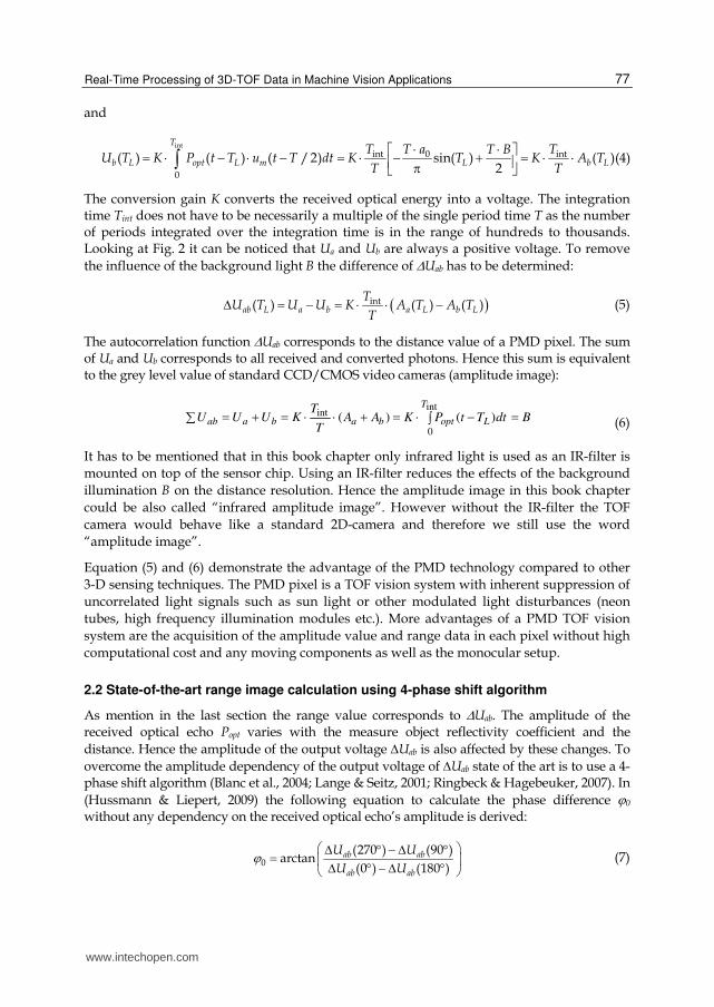
Fig. 8 shows the distance image without motion compensation using the pseudo 4-phase
shift algorithm. Again it can be seen that the distance at the object edges are not calculated
correctly (area 1 and area 3) and that the standard deviation is larger than in the other
areas (see table 2). However the distorted edges are smaller as only two image captures
are needed to calculate the distance. It can be also noticed that the distance image in
Fig. 8 (a) is noisier than in Fig. 8 (b) due to the calibration method proposed in (Hussmann
et al., 2011a).
(a) (b)
(c) (d)
www.intechopen.com

Real-Time Processing of 3D-TOF Data in Machine Vision Applications
85
(a)
(b)
Fig. 7. Distance image using state-of-the-art 4-phase shift algorithm without calibration (a) and with calibration (b).
area 1
area 2
area 3
area 4
area 1
area 2
area 3
area 4
www.intechopen.com
Machine Vision – Applications and Systems
86
(a)
(b)
Fig. 8. Distance image using pseudo 4-phase shift algorithm without calibration (a) and with calibration (b).
area 1
area 2
area 3
area 4
area 1
area 2
area 3
area 4
www.intechopen.com

Real-Time Processing of 3D-TOF Data in Machine Vision Applications
87
Fig. 9 shows the distance image with motion compensation using the 4-phase shift
algorithm. The distance image has clear edges without any distance uncertainties and the
object dimensions can be calculated correctly. However it can be noticed again that the
distance image in Fig. 9 (a) is noisier than in Fig. 9 (b) due to the calibration method
proposed in (Hussmann et al., 2011a).
(a)
(b)
Fig. 9. Distance image using motion compensation algorithm based on the 4-phase shift algorithm without calibration (a) and with calibration (b).
area 1
area 2
area 3
area 1
area 2
area 3
area 4
area 4
www.intechopen.com

Machine Vision – Applications and Systems
88
Fig. 10 shows the distance image with motion compensation using the pseudo 4-phase shift algorithm. The distance image has also clear edges without any distance uncertainties and the object dimensions can be calculated correctly. However it can be noticed again that the distance image in Fig. 10 (a) is noisier than in Fig. 10 (b) due to the calibration method proposed in (Hussmann et al., 2011a).
(a)
(b)
Fig. 10. Distance image using motion compensation algorithm based on the pseudo 4-phase shift algorithm without calibration (a) and with calibration (b).
area 1
area 2
area 3
area 4
area 1
area 2
area 3
area 4
www.intechopen.com
Real-Time Processing of 3D-TOF Data in Machine Vision Applications
89
Distance image
(marked area)
Mean value and Standard deviation in cm
State-of-the-art
4-phase shift
algorithm
Pseudo 4-
phase shift
algorithm
Motion
compensation
algorithm
(4-phase shift
algorithm)
Motion
compensation
algorithm
(pseudo 4-phase
shift algorithm)
area 1
uncalibrated 100.2/1.8 99.0/4.5 104.5/2.3 100.7/4.2
area 1 calibrated 102.0/3.9 127.6/4.4 104.2/0.8 131.0/1.4
area 2
uncalibrated 95.1/0.8 93.1/4.5 95.4/2.7 93.1/4.3
area 2 calibrated 95.5/0.8 125.9/1.0 95.8/0.9 125.8/0.9
area 3
uncalibrated 101.6/2.4 96.6/5.7 95.3/3.0 93.7/4.4
area 3 calibrated 97.5/5.1 130.3/9.0 95.1/1.6 125.2/1.4
area 4
uncalibrated 102.7/0.6 104.9/3.7 103.1/2.2 105.1/3.8
area 4 calibrated 103.5/0.6 130.7/0.7 103.7/0.6 130.5/0.7
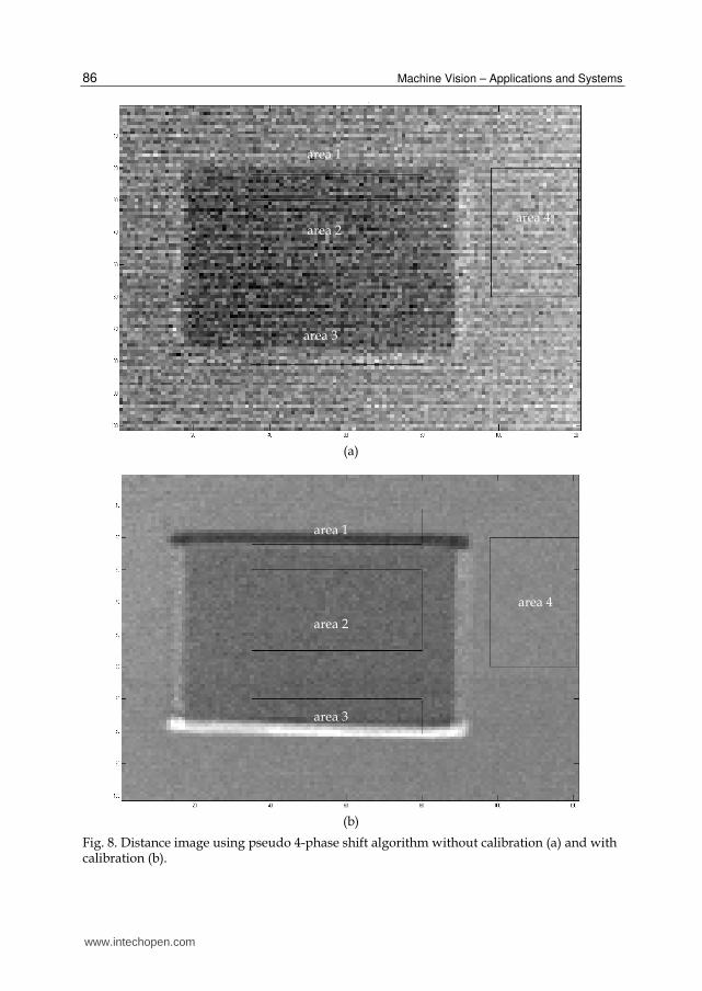
Table 2. Spatial noise of the distance images in Fig. 7 – Fig. 10
The mean value and standard deviation across all pixels within the marked areas in Fig. 7 –
Fig. 10 has been calculated and the results are shown in table 2. It can be clearly seen that the
proposed motion compensation algorithm (with calibration) in (Hussmann et al., 2011a)
combined with the pseudo-four-phase-shift algorithm proposed in (Hussmann & Edeler,
2010) has almost the same standard deviation for the background (area 4) and the object
(area 2) as the state-of-the-art 4-phase shift algorithm and the motion compensation
algorithm (with calibration) in (Hussmann et al., 2011a). However the mean value of the
proposed motion compensation algorithm (with calibration) has an offset due to the
calibration. Hence this offset has to be calibrated as well. Anyhow the proposed
combination algorithm is working at the double frame rate, which is a desired feature for
machine vision applications.
4. Conclusion
In this chapter we highlighted the advantages of the PMD technology for machine vision
applications compared to other range measurement systems. The equations needed for the
design of such a system are derived and demonstrate the simplicity of the extraction of the
range information. A PMD camera delivers absolute geometrical dimensions of objects
www.intechopen.com

Machine Vision – Applications and Systems
90
without depending on the object surface, - distance, -rotation and –illumination. Hence
PMD TOF vision systems are rotation-, translation- and illumination invariant.
The major advantage of the PMD technology is the delivery of an evenly distributed range
and intensity images because each pixel calculates a range and intensity value. The PMD
technology has an inherent suppression of uncorrelated light signals such as sun light or
other modulated light disturbances. However if those light sources saturate the sensor, the
range information is lost. More advantages of the PMD technology are the acquisition of the
intensity and range data in each pixel without high computational cost and any moving
components as well as the monocular setup. All these advantages lead to a compact and
economical design of 3D TOF vision system with a high frame rate. This vision system can
not only be used for machine vision applications but also for many other applications such
as robotic, automotive, medical and multimedia applications.
In this chapter experimental results of a modified motion artefact compensation algorithm
for PMD TOF vision system for a typical machine vision application are presented. Distance
uncertainties at the object edges are greatly reduced. However a calibration (multiplicative
shading correction) has to be done before to achieve this performance. The experimental
results show that the proposed modified algorithm is working at the double frame rate
compared to the original motion artefact compensation algorithm with almost the same
performance. For real-time machine vision applications it is very important to have a high
frame rate. The proposed algorithm will be more suited as only two image captures are
needed instead of four to calculate the distance image.
The aim of the proposed motion compensation algorithm is to remove the displacement
between the same target object points in the amplitude images due to the target movement.
Subsequently the compensated amplitude images are used to calculate the distance image.
Hence the target object must not have a uniformly reflecting surface. For the same reason
the object orientation or form also does not affect the performance of the proposed
algorithm.
It has to be noticed that the proposed modified motion artefact compensation algorithm
(and also the original algorithm) only works for constant lateral movements. Speed
changes are not taken into account, which would result in distance uncertainties at the
object edges. But still the proposed method is able to determine the 3D dimension
measurement of fast moving objects with a higher precision than the state-of-the art 4-
phase-shift algorithm.
The performance of the proposed modified motion artefact compensation algorithm is
investigated offline using Matlab. It has been shown that the algorithm is working at the
double frame rate compared to the original motion artefact compensation algorithm. The
maximum frame rate of the used commercial camera (PMD[vision]® CamCube 2.0) is 25 fps,
which corresponds to a capture time of 40 ms per image. If the proposed algorithm would
be implemented into the PMD camera, the frame rate would increase to 50 fps and a capture
time of 20 ms respectively. If the hardware arctangent function in section 2.4, which has a
total processing time for one range image of 6.66 ms, would be implemented as well, there
would be 13.34 ms left for the remaining processing. This time is long enough to calculate
www.intechopen.com

Real-Time Processing of 3D-TOF Data in Machine Vision Applications
91
the range data in real-time. Hence it can be concluded that the proposed algorithms are well
suited for machine vision applications.
5. Acknowledgment
This work was supported in part by the European Union (European Regional Development
Fund - EFRE) and in part by the federal state of Schleswig Holstein in Germany
(Zukunftsprogramm Wirtschaft). The authors are grateful for the financial support.
6. References
Blanc, N., Oggier, T., Gruener, G., Weingarten, J., Codourey, A. & Seitz, P. (2004).
Miniaturized smart cameras for 3D-imaging in real-time, Proc. of the IEEE Sensors,
vol.1, pp. 471-4
Hu, G. & Stockman, G. (1989). 3-D Surface Solution Using Structured Light and Constraint
Propagation, IEEE Trans. Pattern Anal. Machine Intell., 11(4), pp. 390-402
Hussmann, S. & Hess, H. (2006). Dreidimensionale Umwelterfassung, Trade Journal:
"Elektronik automotive", WEKA Publisher House, Issue 8, ISSN 1614-0125, pp.
55-59
Hussmann, S., Ringbeck, T. & Hagebeuker, B. (2008). A performance review of 3D TOF
vision systems in comparison to stereo vision systems, In: Stereo Vision (Online
book publication), I-Tech Education and Publishing, Vienna, Austria, ch. 7, ISBN
978-953-7619-22-0, pp. 103-120
Hussmann, S. & Liepert, T. (2009). 3D-TOF Robot Vision System, IEEE Trans. on
Instrumentation and Measurement, 58(1), pp. 141-146
Hussmann, S. & Edeler, T. (2010). Pseudo 4-phase shift algorithm for performance
enhancement of 3D-TOF vision systems, IEEE Trans. on Instrumentation and
Measurement, 59(5), pp. 1175-1181
Hussmann, S., Hermanski, A. & Edeler, T. (2011). Real-Time Motion Artifact Suppression in
TOF Camera Systems, IEEE Trans. on Instrumentation and Measurement, 60(5), pp.
1682-1690
Hussmann, S., Knoll, F. & Edeler, T. (2011). Real-time image Processing of TOF range
images using a reconfigurableprocessor system, Proc. SPIE Vol.8085, Videometrics,
Range Imaging and Applications XI, pp. 808507 (8)
Jarvis, R. A. (1983). A perspective on range finding techniques for computer vision, IEEE
Trans. Pattern Anal. Machine Intell., 5(2), pp. 122-139
Lange, R. & Seitz, P. (2001). Solid-state time-of-flight range camera, IEEE Journal of Quantum
Electronics, vol. 37, no. 3, pp. 390–397
Nuechter, A., Surmann, H. & Hertzberg, J. (2003). Automatic model refinement for 3D
reconstruction with mobile robots, Proc. of the 4th IEEE Intl. Conference on Recent
Advances in 3D Digital Imaging and Modeling, pp. 394–401
PMD Technologies, http://pmdtec.com (last accessed August 2011)
Ringbeck, T. & Hagebeuker, B. (2007). A 3D Time of flight camera for object detection, Proc.
of the 8th Conf. On Optical 3-D Measurement Techniques, Zürich, Online-publication:
www.intechopen.com

Machine Vision – Applications and Systems
92
(http://www.pmdtec.com/fileadmin/pmdtec/downloads/publications/200705_P
MD_ETHZuerich.pdf)
Schwarte, R., Xu, Z., Heinol, H., Olk, J., Klein, R., Buxbaum, B., Fischer H. & Schulte, J.
(1997). New electro-optical mixing and correlating sensor: facilities and
applications of the photonic mixer device (PMD), Proc. SPIE, vol. 3100, pp. 245-53
www.intechopen.com

Machine Vision - Applications and SystemsEdited by Dr. Fabio Solari
ISBN 978-953-51-0373-8Hard cover, 272 pagesPublisher InTechPublished online 23, March, 2012Published in print edition March, 2012
InTech EuropeUniversity Campus STeP Ri Slavka Krautzeka 83/A 51000 Rijeka, Croatia Phone: +385 (51) 770 447 Fax: +385 (51) 686 166www.intechopen.com
InTech ChinaUnit 405, Office Block, Hotel Equatorial Shanghai No.65, Yan An Road (West), Shanghai, 200040, China
Phone: +86-21-62489820 Fax: +86-21-62489821
Vision plays a fundamental role for living beings by allowing them to interact with the environment in aneffective and efficient way. The ultimate goal of Machine Vision is to endow artificial systems with adequatecapabilities to cope with not a priori predetermined situations. To this end, we have to take into account thecomputing constraints of the hosting architectures and the specifications of the tasks to be accomplished, tocontinuously adapt and optimize the visual processing techniques. Nevertheless, by exploiting the low?costcomputational power of off?the?shell computing devices, Machine Vision is not limited any more to industrialenvironments, where situations and tasks are simplified and very specific, but it is now pervasive to supportsystem solutions of everyday life problems.
How to referenceIn order to correctly reference this scholarly work, feel free to copy and paste the following:
Stephan Hussmann, Torsten Edeler and Alexander Hermanski (2012). Real-Time Processing of 3D-TOF Datain Machine Vision Applications, Machine Vision - Applications and Systems, Dr. Fabio Solari (Ed.), ISBN: 978-953-51-0373-8, InTech, Available from: http://www.intechopen.com/books/machine-vision-applications-and-systems/real-time-processing-of-3d-tof-data-in-machine-vision-applications

© 2012 The Author(s). Licensee IntechOpen. This is an open access articledistributed under the terms of the Creative Commons Attribution 3.0License, which permits unrestricted use, distribution, and reproduction inany medium, provided the original work is properly cited.