Real time 4D IMRT treatment planning based on a dynamic ...
12
Real time 4D IMRT treatment planning based on a dynamic virtual patient model: Proof of concept Bingqi Guo a) Radiation Oncology, University of Michigan, Ann Arbor, Michigan 48109 X. George Xu Nuclear Engineering and Engineering Physics, Rensselaer Polytechnic Institute, Troy, New York 12180 Chengyu Shi Radiation Oncology, St. Vincent’s Medical Center, Bridgetport, Connecticut 06606 (Received 16 November 2010; revised 28 March 2011; accepted for publication 28 March 2011; published 6 May 2011) Purpose: To develop a novel four-dimensional (4D) intensity modulated radiation therapy (IMRT) treatment planning methodology based on dynamic virtual patient models. Methods: The 4D model-based planning (4DMP) is a predictive tracking method which consists of two main steps: (1) predicting the 3D deformable motion of the target and critical structures as a function of time during treatment delivery; (2) adjusting the delivery beam apertures formed by the dynamic multi-leaf collimators (DMLC) to account for the motion. The key feature of 4DMP is the application of a dynamic virtual patient model in motion prediction, treatment beam adjustment, and dose calculation. A lung case was chosen to demonstrate the feasibility of the 4DMP. For the lung case, a dynamic virtual patient model (4D model) was first developed based on the patient’s 4DCT images. The 4D model was capable of simulating respiratory motion of different patterns. A model-based registration method was then applied to convert the 4D model into a set of deforma- tion maps and 4DCT images for dosimetric purposes. Based on the 4D model, 4DMP treatment plans with different respiratory motion scenarios were developed. The quality of 4DMP plans was then compared with two other commonly used 4D planning methods: maximum intensity projection (MIP) and planning on individual phases (IP). Results: Under regular periodic motion, 4DMP offered similar target coverage as MIP with much better normal tissue sparing. At breathing amplitude of 2 cm, the lung V 20 was 23.9% for a MIP plan and 16.7% for a 4DMP plan. The plan quality was comparable between 4DMP and IP: PTV V 97 was 93.8% for the IP plan and 93.6% for the 4DMP plan. Lung V 20 of the 4DMP plan was 2.1% lower than that of the IP plan and D max to cord was 2.2 Gy higher. Under a real time irregular breathing pattern, 4DMP had the best plan quality. PTV V 97 was 90.4% for a MIP plan, 88.6% for an IP plan and 94.1% for a 4DMP plan. Lung V 20 was 20.1% for the MIP plan, 17.8% for the IP plan and 17.5% for the 4DMP plan. The deliverability of the real time 4DMP plan was proved by calculating the maximum leaf speed of the DMLC. Conclusions: The 4D model-based planning, which applies dynamic virtual patient models in IMRT treatment planning, can account for the real time deformable motion of the tumor under dif- ferent breathing conditions. Under regular motion, the quality of 4DMP plans was comparable with IP and superior to MIP. Under realistic motion in which breathing amplitude and period change, 4DMP gave the best plan quality of the three 4D treatment planning techniques. V C 2011 American Association of Physicists in Medicine. [DOI: 10.1118/1.3578927] Key words: 4D IMRT, virtual patient models, treatment planning, respiratory motion I. INTRODUCTION Respiratory motion causes dose errors in radiation therapy treatment planning and delivery. 1 For intensity modulated radiation therapy (IMRT), tracking using the dynamic multi- leaf collimators (DMLC) is one of the most efficient meth- ods of motion management. The tracking method measures the motion of the tumor and adapts the DMLCs to follow the tumor motion. 2 To compensate for rigid target motion, theo- retical methods have been proposed to superimpose one dimensional (1D), 3,4 two dimensional (2D), 4–6 and three dimensional (3D) 7–10 target trajectories onto MLC leaf tra- jectories. 11 To compensate for deformable target motion, four dimensional computed tomography (4DCT) is com- monly used. Three-dimensional IMRT plans were individu- ally developed on all phases of the 4DCT and 4D leaf sequencing algorithms were then used to combine the plans on individual phases. 12 Though using different algorithms to account for motion, these “conventional” tracking methods have the same workflow: measuring the target motion prior to treatments, creating 4D leaf sequences in treatment plan- ning to account for motion, and delivering the 4D leaf 2639 Med. Phys. 38 (5), May 2011 0094-2405/2011/38(5)/2639/12/$30.00 V C 2011 Am. Assoc. Phys. Med. 2639
Transcript of Real time 4D IMRT treatment planning based on a dynamic ...

Real time 4D IMRT treatment planning based on a dynamic virtual patientmodel: Proof of concept
Bingqi Guoa)
Radiation Oncology, University of Michigan, Ann Arbor, Michigan 48109
X. George XuNuclear Engineering and Engineering Physics, Rensselaer Polytechnic Institute, Troy, New York 12180
Chengyu ShiRadiation Oncology, St. Vincent’s Medical Center, Bridgetport, Connecticut 06606
(Received 16 November 2010; revised 28 March 2011; accepted for publication 28 March 2011;
published 6 May 2011)
Purpose: To develop a novel four-dimensional (4D) intensity modulated radiation therapy (IMRT)
treatment planning methodology based on dynamic virtual patient models.
Methods: The 4D model-based planning (4DMP) is a predictive tracking method which consists of
two main steps: (1) predicting the 3D deformable motion of the target and critical structures as a
function of time during treatment delivery; (2) adjusting the delivery beam apertures formed by the
dynamic multi-leaf collimators (DMLC) to account for the motion. The key feature of 4DMP is the
application of a dynamic virtual patient model in motion prediction, treatment beam adjustment,
and dose calculation. A lung case was chosen to demonstrate the feasibility of the 4DMP. For the
lung case, a dynamic virtual patient model (4D model) was first developed based on the patient’s
4DCT images. The 4D model was capable of simulating respiratory motion of different patterns. A
model-based registration method was then applied to convert the 4D model into a set of deforma-
tion maps and 4DCT images for dosimetric purposes. Based on the 4D model, 4DMP treatment
plans with different respiratory motion scenarios were developed. The quality of 4DMP plans was
then compared with two other commonly used 4D planning methods: maximum intensity projection
(MIP) and planning on individual phases (IP).
Results: Under regular periodic motion, 4DMP offered similar target coverage as MIP with much
better normal tissue sparing. At breathing amplitude of 2 cm, the lung V20 was 23.9% for a MIP
plan and 16.7% for a 4DMP plan. The plan quality was comparable between 4DMP and IP: PTV
V97 was 93.8% for the IP plan and 93.6% for the 4DMP plan. Lung V20 of the 4DMP plan was
2.1% lower than that of the IP plan and Dmax to cord was 2.2 Gy higher. Under a real time irregular
breathing pattern, 4DMP had the best plan quality. PTV V97 was 90.4% for a MIP plan, 88.6% for
an IP plan and 94.1% for a 4DMP plan. Lung V20 was 20.1% for the MIP plan, 17.8% for the IP
plan and 17.5% for the 4DMP plan. The deliverability of the real time 4DMP plan was proved by
calculating the maximum leaf speed of the DMLC.
Conclusions: The 4D model-based planning, which applies dynamic virtual patient models in
IMRT treatment planning, can account for the real time deformable motion of the tumor under dif-
ferent breathing conditions. Under regular motion, the quality of 4DMP plans was comparable with
IP and superior to MIP. Under realistic motion in which breathing amplitude and period change,
4DMP gave the best plan quality of the three 4D treatment planning techniques. VC 2011 AmericanAssociation of Physicists in Medicine. [DOI: 10.1118/1.3578927]
Key words: 4D IMRT, virtual patient models, treatment planning, respiratory motion
I. INTRODUCTION
Respiratory motion causes dose errors in radiation therapy
treatment planning and delivery.1 For intensity modulated
radiation therapy (IMRT), tracking using the dynamic multi-
leaf collimators (DMLC) is one of the most efficient meth-
ods of motion management. The tracking method measures
the motion of the tumor and adapts the DMLCs to follow the
tumor motion.2 To compensate for rigid target motion, theo-
retical methods have been proposed to superimpose one
dimensional (1D),3,4 two dimensional (2D),4–6 and three
dimensional (3D)7–10 target trajectories onto MLC leaf tra-
jectories.11 To compensate for deformable target motion,
four dimensional computed tomography (4DCT) is com-
monly used. Three-dimensional IMRT plans were individu-
ally developed on all phases of the 4DCT and 4D leaf
sequencing algorithms were then used to combine the plans
on individual phases.12 Though using different algorithms to
account for motion, these “conventional” tracking methods
have the same workflow: measuring the target motion prior
to treatments, creating 4D leaf sequences in treatment plan-
ning to account for motion, and delivering the 4D leaf
2639 Med. Phys. 38 (5), May 2011 0094-2405/2011/38(5)/2639/12/$30.00 VC 2011 Am. Assoc. Phys. Med. 2639

sequences in treatments. Accurate tracking requires the
motion of the tumor during treatment delivery to be consist-
ent with the motion measured prior to treatment. However,
studies have shown that significant changes in tumor motion
exist from one delivery fraction to another13 or even within a
fraction.14,15 Therefore, to account for the realistic motion
of the tumor during an IMRT delivery fraction, real time
tracking methods have been investigated. Similar to
“conventional” tracking, real-time tracking first acquires
prior information of the tumor motion and then creates the
4D leaf sequences. During a realistic delivery, the real-time
tumor motion was measured and the leaf sequences for a 4D
delivery were then modified online to account for the differ-
ence between measured and planned motions. Prediction
methods1,16–18 were usually used in real time tracking to
account for the latency effect between the detection of
motion to the modification of the delivery beam. The Syn-
chrony system (Accuray, Sunnyvale, CA) is an example of
real-time tracking delivery. Synchrony measures the target
motion using a combination of infrared cameras and x-ray
and accounts for the motion using a robotic arm.19 For
IMRT, Sawant et al.20 proposed a real time tracking method
for 3D rigid target motion and proved that the geometric ac-
curacy of this method was less than 2 mm for respiratory
motion.21 However, both synchrony and Sawant’s method
did not consider the deformation of the targets. Yi et al.22
took another approach for real time tracking: the pro-
grammed 4D leaf sequences were delivered with dose rate
regulated online to account for the change of breathing pat-
tern during treatment deliveries. This method only consid-
ered the change of breathing frequency, although the change
of breathing amplitude may also affect the tracking accu-
racy. Another common problem of current real time tracking
methods is that these methods do not consider the interplay
effect of the motion of tumor and the motion of the MLC
leaves in deliveries and the realistic delivered doses during
real time tracking cannot be calculated.
Given the limitations of current tracking methods, an
ideal real time tracking method should have a few features:
(1) it should account for the 3D deformable motion of the
targets; (2) it should not require motion reproducibility; (3)
it should be able to calculate the dose to patients during a re-
alistic delivery with consideration of the interplay effect.
Difficulties in developing such an ideal real time tracking
method are twofold. First, measuring the real time 3D de-
formable motion of targets online exceeds the capability of
current imaging techniques. The most commonly used imag-
ing tool to measure the deformable motion of structures in
today’s radiotherapy is 4DCT. However, 4DCT cannot be
acquired and reconstructed in real-time so that it is not suita-
ble for online motion detection. Second, changing the pre-
programmed 4D MLC leaf sequences online may break the
synchronization between the 4D leaf sequences with the re-
spiratory motion.
The first problem mentioned above may be addressed by
using motion modeling. Modeling the 3D deformable motion
of the tumor and the organs of a specific patient has been
made possible with the rapid development of computational
modeling techniques. Dynamic models of the lungs, the liver
and the prostate have been developed23–29 and used in radia-
tion therapy applications.30–33 Compared with 4DCT, 4D
models have a few advantages including better temporal re-
solution and flexibility of motion pattern change so they may
be used in guidance for real time tracking delivery.
The second problem, loss of synchronization between the
4D leaf sequences with online motion, could be solved by
introducing a new tracking concept: predictive tracking. In
real time tracking, the temporal information of the motion
recorded prior to treatment is incorporated into the 4D leaf
sequences so that online modification of the 4D sequences
may break the synchronization between the leaf motion and
the target motion. However, if the 4D sequencing step is
skipped and the motion predicted online is directly used to
modify the leaf positions from a 3D IMRT treatment plan
without temporal information, loss of synchronization is less
likely to happen. The method to directly convert a 3D IMRT
plan to real-time delivery based on predicted motion is
termed as predictive tracking. Figure 1 compares the work-
flow of “conventional” tracking, “real time” tracking, and
“predictive” tracking.
Based on advanced motion modeling techniques and the
predictive tracking concept, this study proposed a real time
4D IMRT planning method, called 4D model-based planning
(4DMP). 4DMP is capable of accounting for the deformable
motion of the target and critical structures in real time and
calculating the delivered 4D doses with consideration of
interplay effects during treatment deliveries. The feasibility
of the 4DMP method was investigated in this study and
the quality of 4DMP was compared with two other com-
monly used 4D treatment planning techniques: maximum in-
tensity projection (MIP)34 and planning on individual
phases (IP).12
II. MATERIALS AND METHODS
The 4DMP is a predictive tracking method consisting of
two main steps: motion prediction and delivery beam adapta-
tion. The basis of 4DMP is a dynamic virtual patient model,
which is used to predict the motion, to adapt the delivery
beams and to calculate the dose. Section II A introduces the
techniques used to reconstruct a predictive virtual patient
model from the 4DCT and the breathing curve of a patient.
Section II B explains how to apply a virtual patient model
for dose calculation, which is the basis of model-based treat-
ment planning. Section II C then introduces the steps of
4DMP and compares it with MIP and IP.
II.A. Creation of a predictive dynamic virtual patientmodel
II.A.1. 4DCT acquisition
A 4DCT scan of a lung patient under quiet breathing was
the main resource for the 4D model reconstruction. The CT
images were acquired using a LightSpeed 16-slice CT (Gen-
eral Electric, WI) with a slice thickness of 2.5 mm. The scan
2640 Guo, Xu, and Shi: Model based 4D IMRT treatment planning 2640
Medical Physics, Vol. 38, No. 5, May 2011

took around 2 min. Respiratory signal was simultaneously
acquired via the Varian real time respiratory position man-
agement (RPM) system (Varian Corporation, Palo Alto,
CA). The CT images were then retrospectively sorted into
10 distinct phases (p0, p10, …, p90) corresponding to the
phases of a respiratory cycle. P0 was defined as the end-
inhale phase and p50 was the end-exhale phase. A single cli-
nician segmented the gross tumor volume (GTV) and the
organs at risk (OAR) on all phases. These contours were
used as the “gold standard” for model reconstruction.
A “reference phase” was selected from the ten phases for
model reconstruction and treatment planning. Considering
that the end-inhale phase p0 is commonly the most stable
phase, p0 was chosen as the reference phase. The mean am-
plitude of the breathing curve recorded at 4DCT acquisition
was 1.0 cm and the mean period was 4.4 s.
II.A.2. 3D whole body NURBS model reconstruction
Contours of structures in the reference phase were
converted to a three-dimensional (3D) whole body non-
uniform rational B-spline (NURBS) model33 in two main
steps:
(1) Polygonzation. For each structure, control points were
automatically sampled from the original contours using
an in-house code based on MATLAB.35 A polygon of the
structure was then formed by the control points. The
code was designed to maintain the volume and the shape
of the polygon the same as those of the original contours
while keeping the number of control points as few as
possible to reduce computation time.
(2) Conversion to NURBS surfaces. The structure poly-
gons were then converted to three- degree NURBS surfa-
ces using NURBS toolbox of MATLAB. Figure 2(a)
compares the original contours, the polygon and the
NURBS surface for the right lung. A 3D whole body
model was then created as a collection of the 3D
NURBS surfaces of the tumor and other organs at the
reference phase.
II.A.3. Extending the 3D model to a 4D model basedon 4DCT
The 3D whole body model developed on the end-inhale
phase was propagated to other phases using the structure
contours delineated on those phases. The 3D models of the
tumor and other organs were transformed individually by
shifting the control points forming the models so that the
transformed models matched the structure contours on
another phase. For a structure experiencing mainly translo-
cation and rotation, such as the kidneys, the structure was
treated as an entity in transformation. For a structure expe-
riencing deformation, such as lungs and tumor, control
points of structures were transformed individually. A pro-
cedure called “optimized deformation” was developed to
automatically transform organ models. The concept of
FIG. 1. Comparing the workflow of “conventional” tracking, real time tracking and predictive tracking.
2641 Guo, Xu, and Shi: Model based 4D IMRT treatment planning 2641
Medical Physics, Vol. 38, No. 5, May 2011
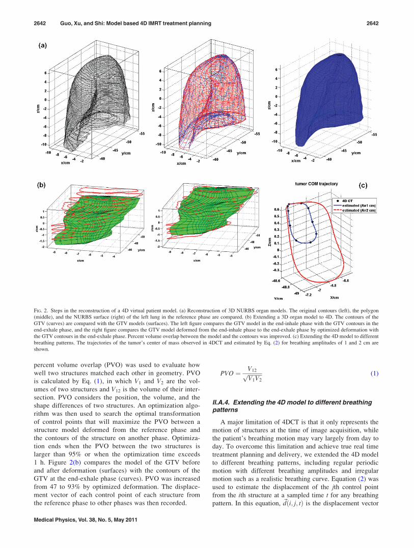
percent volume overlap (PVO) was used to evaluate how
well two structures matched each other in geometry. PVO
is calculated by Eq. (1), in which V1 and V2 are the vol-
umes of two structures and V12 is the volume of their inter-
section. PVO considers the position, the volume, and the
shape differences of two structures. An optimization algo-
rithm was then used to search the optimal transformation
of control points that will maximize the PVO between a
structure model deformed from the reference phase and
the contours of the structure on another phase. Optimiza-
tion ends when the PVO between the two structures is
larger than 95% or when the optimization time exceeds
1 h. Figure 2(b) compares the model of the GTV before
and after deformation (surfaces) with the contours of the
GTV at the end-exhale phase (curves). PVO was increased
from 47 to 93% by optimized deformation. The displace-
ment vector of each control point of each structure from
the reference phase to other phases was then recorded.
PVO ¼ V12ffiffiffiffiffiffiffiffiffiffiV1V2
p (1)
II.A.4. Extending the 4D model to different breathingpatterns
A major limitation of 4DCT is that it only represents the
motion of structures at the time of image acquisition, while
the patient’s breathing motion may vary largely from day to
day. To overcome this limitation and achieve true real time
treatment planning and delivery, we extended the 4D model
to different breathing patterns, including regular periodic
motion with different breathing amplitudes and irregular
motion such as a realistic breathing curve. Equation (2) was
used to estimate the displacement of the jth control point
from the ith structure at a sampled time t for any breathing
pattern. In this equation, ~dði; j; tÞ is the displacement vector
FIG. 2. Steps in the reconstruction of a 4D virtual patient model. (a) Reconstruction of 3D NURBS organ models. The original contours (left), the polygon
(middle), and the NURBS surface (right) of the left lung in the reference phase are compared. (b) Extending a 3D organ model to 4D. The contours of the
GTV (curves) are compared with the GTV models (surfaces). The left figure compares the GTV model in the end-inhale phase with the GTV contours in the
end-exhale phase, and the right figure compares the GTV model deformed from the end-inhale phase to the end-exhale phase by optimized deformation with
the GTV contours in the end-exhale phase. Percent volume overlap between the model and the contours was improved. (c) Extending the 4D model to different
breathing patterns. The trajectories of the tumor’s center of mass observed in 4DCT and estimated by Eq. (2) for breathing amplitudes of 1 and 2 cm are
shown.
2642 Guo, Xu, and Shi: Model based 4D IMRT treatment planning 2642
Medical Physics, Vol. 38, No. 5, May 2011

of a control point and Ao is the amplitude of breathing in
4DCT, which is also the mean amplitude of the breathing
curve at 4DCT acquisition. In this study, Ao ¼ 1 cm. hðtÞ and
AðtÞ are the phase and the amplitude of a breathing curve at
time t, and ~f stands for a three-degree B-spline interpolation
between the phase of breathing and the displacement of the
control point with breathing amplitude Ao. The displacement
vectors of the control point at 10 phases ~dði; j; pÞ;p ¼ 0; 1:::9 were used to determine ~f . This equation pre-
serves the motion of structures observed in 4DCT including
the hysteresis effect and allows extrapolation of motion
range beyond 4DCT. By using this equation, it was assumed
that the amplitude of internal organ motion was linearly pro-
portional to the amplitude of the breathing curve. For a dif-
ferent internal-external relationship, the AðtÞ=Ao term in Eq.
(2) may be changed accordingly. Figure 2(c) compares the
trajectory of the center of mass (COM) of the GTV observed
in the 4DCT and the estimated GTV COM trajectories for
breathing amplitude of 1 cm (same as the breathing ampli-
tude of 4DCT) and 2 cm, respectively.
~dði; j; tÞ ¼~f ~dði; j; pÞ; hðtÞ� �
AðtÞð ÞA0
: (2)
Structures in the thoracic and abdominal cavities are close to
each other so when the structures are set in motion in a 4D
model, the organ surfaces may “collide”. To avoid the inter-
section of structures, a collision detection and correction algo-
rithm was applied. Each structure was assigned an “elasticity
coefficient” E so that when two structures collide with each
other, the contact surfaces of both structures will deform. The
extent of deformation is inversely proportional to the elastic-
ity coefficient of the structure. Collision detection and correc-
tion is particularly important when extending the 4D model to
motion range larger than that measured in 4DCT.
II.A.5. Predictive 4D virtual patient model
When a real-time breathing curve was used in Eq. (2) to
estimate the motion of control points, the model was
regarded as a “real-time” 4D virtual patient model. Further-
more, if combining the real-time motion with a motion pre-
diction algorithm, the 4D model can be updated to
“predictive” virtual human model and be used for predictive
tracking. In this study, we assumed a prefect prediction algo-
rithm was used so that the predicted breathing curve is
exactly the same as the measured. Possible errors caused by
this assumption will be discussed later.
II.B. Applying the 4D virtual patient models indosimetry
II.B.1. Extracting deformation maps and 4DCT imagesfrom a dynamic model
To calculate doses from treatment plans to a 4D model,
the model may be converted back to sets of 4DCT images
using the 3D CT images of the reference phase and the de-
formation maps extracted from the 4D model. This proce-
dure is termed as “model based registration”. The motion/
deformation of a NURBS organ model is represented by the
displacement of control points defining the surface of the
model. Due to the lack of motion information inside the
organ model, it was assumed that the deformation of a struc-
ture propagates linearly from surface to inside. So, the defor-
mation vector of a point within a structure is a function of
the deformation vectors of the control points on the surface
of the structure and the distances of the point to the surface,
as shown by Eq. (3), in which N is the number of control
points defining the structure; dðx; y; zÞ�����!
is the deformation
vector of any point within this structure, ~di is deformation
vector of ith control point and ri is the distance of the point
to that control point.
dðx; y; zÞ�����!
¼RN
i¼11ri
di!
RNi¼1
1ri
(3)
Figure 3 shows the amplitude of the deformation map from
the end-inhale phase to the end-exhale phase with breathing
amplitude of 2 cm. The vertebral column is static during
breathing. Structures such as the liver and the kidneys expe-
rience mainly translocation. Therefore, the amplitude of the
deformation map inside these structures is uniform. The
spleen experiences translocation and rotation, and the lungs
and the tumor experience deformation; thus, the amplitude
of the deformation map within these structures is nonuni-
form. For lungs, voxels near the diaphragm have larger de-
formation amplitudes than voxels near the apex. The
deformation maps were used to create 4DCT images by
deforming the 3D CT images at the reference phase.
II.B.2. Calculating the delivered 4D doses of IMRTplans while considering the realistic motion and theinterplay effect
Model-based registration and CT image deformation
allow dose calculation of IMRT treatments on a real time
scale while taking into account the interplay effect. As illus-
trated in Fig. 4, each IMRT beam is composed of several
segments. Given the synchronization of the measured breath-
ing curve with the beam delivery, the dose delivered by each
beam segment during a realistic IMRT treatment to the
FIG. 3. The amplitude map of deformation (unit: cm) from the end-inhale
phase to the end-exhale phase for a breathing amplitude of 2 cm.
2643 Guo, Xu, and Shi: Model based 4D IMRT treatment planning 2643
Medical Physics, Vol. 38, No. 5, May 2011

deformed geometry can be calculated. For each segment of
the beams, the measured breathing curve at the time of seg-
ment delivery is used to deform the 4D model. The deforma-
tion map is extracted from the deformed model and the 3D
CT images at the time of segment delivery are generated.
Dose delivered by the segment to the 3D CT images is calcu-
lated and registered back to the reference phase. The 4D
delivered dose is then a summation of the segment doses.
Based on the 4D models and the techniques to convert 4D
models to sets of 4DCTs and deformation maps, a 4D treat-
ment planning methodology, model-based 4D planning
(4DMP), is proposed to provide a simple and efficient way
of managing real time intrafraction motion.
II.C. 4D IMRT treatment planning based on 4D virtualpatient models
II.C.1. 4DMP for regular motion
A 4D model provides information on changes in the mor-
phology of the target and critical structures during breathing.
A possible way to apply this information in 4D IMRT treat-
ment planning is to apply the same morphology changes to
treatment beams, called “morphology based 4D planning”.
The “direct aperture deformation” (DAD) method proposed
by Yu et al. is one such technique.36,37 In DAD planning, an
IMRT treatment plan was first developed on the reference
phase, and then the beam apertures of the plan were morphed
to other phases based on the relative shape change of the tar-
get contours in the beam’s eye view (BEV), called segment
aperture morphing. For regular motion, 4DMP planning
adopts the DAD concept except that the dynamic model of
the planning target volume (PTV) instead of the contours of
the PTV is used to deform the segments.
II.C.2. 4DMP for real-time motion
To account for motion during a realistic treatment deliv-
ery, 4DMP combines the segment morphing algorithm of
DAD and a special predictive tracking delivery method. In
real time 4DMP, an IMRT treatment plan is first developed
on the reference phase and then propagated to a realistic
delivery. As illustrated in Fig. 5, right after the delivery of
one beam segment (time t), the system predicts the breathing
curve of the patient with a prediction time, tpredict. The model
of the PTV is then deformed according to the predicted
breathing phase and amplitude. Both the PTV model at the
reference phase and the deformed PTV model are projected
to the BEV of the next segment, and the aperture of the next
segment is then morphed according to the deformation of the
PTV. After the segment morphing, MLC leafs are moved to
form the shape of the next segment, which has been morphed
previously, and the delivery of the next beam segment starts.
To ensure the synchronization of the delivery with the
breathing motion, it is essential that the next beam segment
is delivered at the predicted time, tþ tpredict. In real time
4DMP, the delivery of the next beam segment was designed
to start at tþ tpredict � 1=2MU=DR and finish at
FIG. 4. Calculation of the delivered 4D doses of IMRT treatments with con-
sideration of the realistic motion and the interplay effect. For each segment
of the beams, the measured breathing curve at the time of segment delivery
is used to deform the 4D model. The deformation map is extracted from the
deformed model and the 3D CT images at the time of segment delivery are
generated. Dose delivered by the segment to the 3D CT images is calculated
and registered back to reference phase. The 4D delivered dose is then a sum-
mation of the segment doses.
FIG. 5. Flow chart of real time 4DMP planning/delivery. Right after the
delivery of one beam segment (time t), the system predicts the breathing
curve of the patient for a prediction time tpredict. The model of the PTV is
then deformed according to the predicted breathing phase and amplitude.
Both the PTV model at the reference phase and the deformed PTV model
are projected to the BEV of the next segment, and the aperture of the next
segment is then morphed according to the deformation of the PTV. After the
segment morphing, MLC leaves are moved to form the shape of the next
segment, which has been morphed previously, and the delivery of the next
beam segment starts. To calculate the 4D delivered dose of real-time 4DMP,
for each segment of the beams, the measured breathing curve at the time of
segment delivery is used to deform the 4D model. The deformation map is
extracted from the deformed model and the 3D CT images at the time of
segment delivery are generated. Dose delivered by the segment to the 3D
CT images is calculated and registered back to reference phase. The 4D
delivered dose is then a summation of the segment doses.
2644 Guo, Xu, and Shi: Model based 4D IMRT treatment planning 2644
Medical Physics, Vol. 38, No. 5, May 2011

tþ tpredict þ 1=2MU=DR, in which MU is the number of
monitor units in the next beam segment and DR is the dose
rate. The predicted time tþ tpredict is then right in the middle
of the segment delivery. If we assume that the time for
motion prediction, structure deformation, and aperture
morphing is negligible, the leaves of MLCs have to move
from the previous positions to the new positions within a
time of tpredict � 1=2MU=DR to maintain synchronization
and avoid beam hold offs.
4DMP is a real time planning method that can account for
the irregular, 3D deformable motion of the target during a re-
alistic treatment delivery. It is also a very efficient planning/
delivery technique because the number of segments in a real
time 4DMP plan is the same as the 3D IMRT plan in the ref-
erence phase. The delivered 4D doses of 4DMP plans can be
calculated during or after the real time 4DMP delivery. For
each segment, the measured breathing phase and amplitude
at the time of segment delivery are used to deform the mod-
els of structures, to extract the deformation maps and to cre-
ate the deformed 3D CT images. The delivered dose of each
segment is then calculated using the deformed CT images
and the morphed segment aperture. Segment doses are regis-
tered back to the reference phase and the 4D delivered dose
is the summation of all segment doses.
There are two determining factors affecting the success of
a real time 4DMP delivery: the prediction time between seg-
ments and the residual motion within a segment. The predic-
tion error increases as the prediction time increases, so a
short prediction time is desirable. However, to make sure
that the MLC leaves can travel from the positions of the pre-
vious segment to the positions of the next segment within
the prediction time, it is desirable to have a large prediction
time. As a compromise, we used a prediction time of 200 ms
for arc IMRT plans in this study. The residual motion within
a segment delivery is proportional to the time of segment
delivery and thus inversely proportional to the dose rate. To
reduce the residual motion, it is desirable to select a large
dose rate. In this study, we used a dose rate of 1000 MU/min
for treatment planning.
II.C.3. Comparing 4DMP with MIP and IP under regularmotion
To evaluate the quality of 4DMP plans, we compared the
4DMP with MIP and IP. The three 4D treatment planning
strategies were compared for rotational (arc) IMRT plans.
Both MIP and IP plans assume the reproducibility of the
breathing pattern and ignore the interplay effect, so the qual-
ity of 4DMP plans was first compared with MIP and IP
based on these two assumptions. The 4D virtual patient
model was converted to two sets of 4DCT images, one with
breathing amplitude of 1 cm and the other with a 2 cm
breathing amplitude. Each 4DCT consist of 10 phases with
equal time weightings. Structure contours on each phase and
the deformation maps from the reference phase to other
phases were extracted from the 4D model. The 4DCT images
and the structure contours were imported into Pinnacle3
treatment planning system (Version 9.0, Philips, Fitchburg,
WI) for IMRT treatment planning.
FIG. 6. 4D model at the end-inhale and the end-exhale phases for breathing amplitudes of 1 cm and 2 cm and the corresponding CT images. (a) lungs and
GTV at the end-inhale phase and two end-exhale phases with breathing amplitude of 1 and 2 cm, respectively; (b) CT images at difference breathing phases;
top: the end-inhale phase; middle: deformed CT images at the end-exhale phase with breathing amplitude of 1 cm; bottom: deformed CT images at the end-
exhale phase with breathing amplitude of 2 cm; (c) difference of the CT images between the end-inhale and the end-exhale phases; upper: 1 cm breathing am-
plitude; lower: 2 cm breathing amplitudes.
TABLE I. Motion/deformation of the GTV at different breathing amplitudes
characterized by the volume of tumor, the movement of center of mass
(COM) and the percent volume overlap (PVO) between the end-inhale phase
and the end-exhale phase.
End-inhale
End-exhale
(breathing
amplitude¼ 1 cm)
End-exhale
(breathing
amplitude¼ 2 cm)
Volume (cc) 21.05 19.13 18.19
Movement
of COM
– 0.6 cm 1.3 cm
PVO – 47% 23%
2645 Guo, Xu, and Shi: Model based 4D IMRT treatment planning 2645
Medical Physics, Vol. 38, No. 5, May 2011
For IP planning, the treatment plans were developed inde-
pendently on each of 10 phases. In each phase, the PTV was
defined by expanding the GTV of this phase with a 0.5 cm
set-up margin. 60 Gy was prescribed to the mean dose to the
PTV in 30 fractions for all phases. 4DMP planning used the
same margin and prescription as IP planning. A treatment
plan was developed on the reference phase and then propa-
gated to other phases. For 4DMP and IP planning, the doses
on all 10 phases were registered back to the reference phase
using the deformation maps extracted from model, and the
4D composite doses of IP and 4DMP plans were calculated
by averaging the deformed dose maps. The 4D composite
dose volume histograms (DVHs) for the GTV, PTV and crit-
ical structures were calculated using the 4D composite dose
and the structure contours in the reference phase.
For MIP planning, the treatment plan was developed
using the mean CT image with the internal target volume
(ITV) defined as the union of the GTVs in all 10 phases. The
PTV was defined by expanding the ITV with a 0.5 cm set-up
margin. The prescription was the same as in the 4DMP and
IP plans. To calculate the 4D composite dose distributions of
a MIP IMRT plan, the MIP plan for the mean CT image was
extracted and then imported to the images of all 10 phases.
Dose calculation was performed on individual phases, and
the 4D doses and DVHs were calculated using the same
method as IP and 4DMP plans.
II.C.4. Comparing 4DMP with MIP and IP underrealistic irregular motion
During a realistic IMRT treatment delivery, the target
may move beyond the range seen in 4DCT, and the interplay
between the motion of MLCs and structures may cause fur-
ther deviation of the delivered dose from the planned dose.
Therefore, to compare 4DMP with MIP and IP under
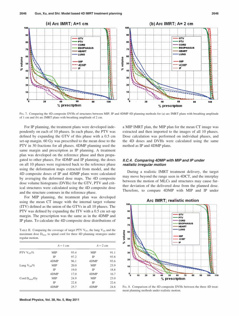
FIG. 7. Comparing the 4D composite DVHs of structures between MIP, IP and 4DMP 4D planning methods for (a) arc IMRT plans with breathing amplitude
of 1 cm and (b) arc IMRT plans with breathing amplitude of 2 cm.
TABLE II. Comparing the coverage of target PTV V97, the lung V20 and the
maximum dose Dmax to spinal cord for three 4D planning strategies under
regular motion.
A¼ 1 cm A¼ 2 cm
PTV V97/% MIP 93.4 MIP 91.1
IP 97.2 IP 93.8
4DMP 96.1 4DMP 93.6
Lung V20/% MIP 20.0 MIP 23.9
IP 19.0 IP 18.8
4DMP 17.0 4DMP 16.7
Cord Dmax/Gy MIP 24.9 MIP 23.0
IP 22.8 IP 22.6
4DMP 25.7 4DMP 24.8 FIG. 8. Comparison of the 4D composite DVHs between the three 4D treat-
ment planning methods under realistic motion.
2646 Guo, Xu, and Shi: Model based 4D IMRT treatment planning 2646
Medical Physics, Vol. 38, No. 5, May 2011

realistic motion, it is necessary to calculate the “delivered
4D doses” while taking into account the interplay effect.
A real time 4DMP treatment plan was developed for the
4D model. The delivery of the first segment was assumed to
start at the beginning of the breathing curve. The delivered
4D doses of the arc 4DMP plans were calculated using the
method shown in Fig. 5. Though MIP and IP plans were not
designed for delivery with irregular motion, we were still
able to estimate the delivered 4D doses of MIP and IP plans
using the 4D virtual patient model, using the method shown
in Fig. 4, as long as the synchronization of beam delivery
with the real time breathing curve was known. For MIP
plans, the delivery of the first segment was also assumed to
start at the beginning of the breathing curve. The times
between the segments were estimated by assuming a con-
stant leaf travel velocity of 2.5 cm/s. An IP plan includes 10
IMRT plans developed on different phases. To determine the
synchronization of the IP plan deliveries with the breathing
curve, we assumed that the first segments of all 10 plans
were delivered in the first cycle of breathing to the corre-
sponding phase. Leaf speed constraints were ignored.
Assuming the number of segments of the 10 IMRT plans is
fNig, where i¼ 1, 2,…, 10, the number of breathing cycles
required to finish an IP plan delivery was the maximum of
fNig. This method assumed that all the segments of the 4D
IP plan were delivered to the correct phase. For MIP and IP
plans, any deviation of the delivered 4D doses from the
planned 4D doses is the result of breathing irregularity and
the interplay effect.
III. RESULTS
III.A. Motion features of the 4D virtual patient model
Figure 6(a) shows the motion of the lungs and the GTV.
The organ surfaces were plot in blue for the end-inhale
phase, green for the end-exhale phase with breathing ampli-
tude of 1 cm and red for the end-exhale phase with breathing
amplitude of 2 cm. Figure 6(b) compares the CT images at
the end-inhale phase (top figure), the end-exhale phase with
breathing amplitude 1 cm (middle figure), and the end-
exhale phase with breathing amplitude 2 cm (bottom). The
difference of CT images at end-inhale and end-exhale phases
were shown in Fig. 6(c). The upper figure is the difference at
breathing amplitude of 1 cm and the lower figure is the dif-
ference at breathing amplitude of 2 cm. The largest CT num-
ber changes were observed near the diaphragm, at the skin-
air interface, at the ribs and at the tumor location. Abdominal
organs also experienced large motion as shown by the defor-
mation map in Fig. 3(b). However, because of the relatively
low contrast in the abdomen, the change of CT number was
not as large as in the thoracic region.
The motion of the GTV, quantified by the change of its
volume and center of mass (COM) and the percent volume
overlap (PVO) between the end-inhale phase and the end-
exhale phase is shown in Table I.
III.B. Dosimetric comparison of different 4D planningstrategies under regular motion
Figure 7 compares the 4D composite DVHs for the target
and critical structures of three 4D treatment planning meth-
ods for (a) arc IMRT plans with breathing amplitude of 1 cm
and (b) arc IMRT plans with breathing amplitude of 2 cm.
TABLE III. Comparing the coverage of target PTV V97, the lung V20 and the
maximum dose Dmax to spinal cord for three 4D planning strategies under
realistic motion.
Realistic motion
PTV V97/% MIP 90.4
IP 89.4
4DMP 94.1
Lung V20/% MIP 20.1
IP 19.0
4DMP 17.5
Cord Dmax/Gy MIP 24.7
IP 23.9
4DMP 26.8
TABLE IV. Comparing the volumes and the COMs of structures between the dynamic model and the original contours for the end-inhale phase and the end-
exhale phase. The percent differences of the volumes and the distances of COMs are listed.
Organs
End-inhale (P0) End-exhale (P50)
Volume/%
COM/mm
Volume/%
COM/mm
x y z x y z
PTV �0.8 �0.04 �0.02 0.00 �0.7 0.04 0.00 �0.01
Esophagus 2.1 �1.48 0.62 1.57 �2.2 �0.30 �0.15 0.30
Heart �3.2 0.15 0.05 �0.30 �3.2 �1.02 �0.16 �0.37
Left lung �1.1 �0.67 �1.22 �0.20 �1.6 �0.62 0.61 0.50
Right lung 3.2 �0.36 0.42 0.05 2.9 �0.26 1.13 �2.71
Left kidney �0.5 0.15 �0.19 0.12 �4.8 0.14 �0.18 �0.02
Right kidney �4.4 0.13 �0.24 0.10 �6.3 0.17 0.31 0.25
Liver �2.0 �0.33 �0.14 0.00 �1.9 �0.30 0.01 �0.12
Spinal cord �0.5 0.10 �0.40 0.30 �0.5 0.10 �0.40 0.30
Spleen �1.5 0.06 0.00 �0.06 �1.8 0.10 �0.10 �0.10
Stomach �0.2 0.52 �0.48 0.35 �5.1 1.09 0.19 0.73
2647 Guo, Xu, and Shi: Model based 4D IMRT treatment planning 2647
Medical Physics, Vol. 38, No. 5, May 2011
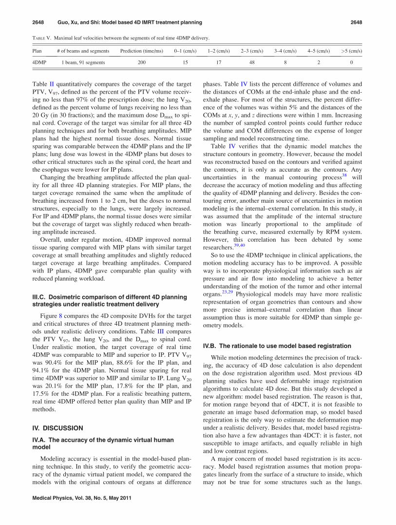
Table II quantitatively compares the coverage of the target
PTV, V97, defined as the percent of the PTV volume receiv-
ing no less than 97% of the prescription dose; the lung V20,
defined as the percent volume of lungs receiving no less than
20 Gy (in 30 fractions); and the maximum dose Dmax to spi-
nal cord. Coverage of the target was similar for all three 4D
planning techniques and for both breathing amplitudes. MIP
plans had the highest normal tissue doses. Normal tissue
sparing was comparable between the 4DMP plans and the IP
plans; lung dose was lowest in the 4DMP plans but doses to
other critical structures such as the spinal cord, the heart and
the esophagus were lower for IP plans.
Changing the breathing amplitude affected the plan qual-
ity for all three 4D planning strategies. For MIP plans, the
target coverage remained the same when the amplitude of
breathing increased from 1 to 2 cm, but the doses to normal
structures, especially to the lungs, were largely increased.
For IP and 4DMP plans, the normal tissue doses were similar
but the coverage of target was slightly reduced when breath-
ing amplitude increased.
Overall, under regular motion, 4DMP improved normal
tissue sparing compared with MIP plans with similar target
coverage at small breathing amplitudes and slightly reduced
target coverage at large breathing amplitudes. Compared
with IP plans, 4DMP gave comparable plan quality with
reduced planning workload.
III.C. Dosimetric comparison of different 4D planningstrategies under realistic treatment delivery
Figure 8 compares the 4D composite DVHs for the target
and critical structures of three 4D treatment planning meth-
ods under realistic delivery conditions. Table III compares
the PTV V97, the lung V20, and the Dmax to spinal cord.
Under realistic motion, the target coverage of real time
4DMP was comparable to MIP and superior to IP. PTV V97
was 90.4% for the MIP plan, 88.6% for the IP plan, and
94.1% for the 4DMP plan. Normal tissue sparing for real
time 4DMP was superior to MIP and similar to IP. Lung V20
was 20.1% for the MIP plan, 17.8% for the IP plan, and
17.5% for the 4DMP plan. For a realistic breathing pattern,
real time 4DMP offered better plan quality than MIP and IP
methods.
IV. DISCUSSION
IV.A. The accuracy of the dynamic virtual humanmodel
Modeling accuracy is essential in the model-based plan-
ning technique. In this study, to verify the geometric accu-
racy of the dynamic virtual patient model, we compared the
models with the original contours of organs at difference
phases. Table IV lists the percent difference of volumes and
the distances of COMs at the end-inhale phase and the end-
exhale phase. For most of the structures, the percent differ-
ence of the volumes was within 5% and the distances of the
COMs at x, y, and z directions were within 1 mm. Increasing
the number of sampled control points could further reduce
the volume and COM differences on the expense of longer
sampling and model reconstructing time.
Table IV verifies that the dynamic model matches the
structure contours in geometry. However, because the model
was reconstructed based on the contours and verified against
the contours, it is only as accurate as the contours. Any
uncertainties in the manual contouring process38 will
decrease the accuracy of motion modeling and thus affecting
the quality of 4DMP planning and delivery. Besides the con-
touring error, another main source of uncertainties in motion
modeling is the internal–external correlation. In this study, it
was assumed that the amplitude of the internal structure
motion was linearly proportional to the amplitude of
the breathing curve, measured externally by RPM system.
However, this correlation has been debated by some
researchers.39,40
So to use the 4DMP technique in clinical applications, the
motion modeling accuracy has to be improved. A possible
way is to incorporate physiological information such as air
pressure and air flow into modeling to achieve a better
understanding of the motion of the tumor and other internal
organs.23,29 Physiological models may have more realistic
representation of organ geometries than contours and show
more precise internal–external correlation than linear
assumption thus is more suitable for 4DMP than simple ge-
ometry models.
IV.B. The rationale to use model based registration
While motion modeling determines the precision of track-
ing, the accuracy of 4D dose calculation is also dependent
on the dose registration algorithm used. Most previous 4D
planning studies have used deformable image registration
algorithms to calculate 4D dose. But this study developed a
new algorithm: model based registration. The reason is that,
for motion range beyond that of 4DCT, it is not feasible to
generate an image based deformation map, so model based
registration is the only way to estimate the deformation map
under a realistic delivery. Besides that, model based registra-
tion also have a few advantages than 4DCT: it is faster, not
susceptible to image artifacts, and equally reliable in high
and low contrast regions.
A major concern of model based registration is its accu-
racy. Model based registration assumes that motion propa-
gates linearly from the surface of a structure to inside, which
may not be true for some structures such as the lungs.
TABLE V. Maximal leaf velocities between the segments of real time 4DMP delivery.
Plan # of beams and segments Prediction (time/ms) 0–1 (cm/s) 1–2 (cm/s) 2–3 (cm/s) 3–4 (cm/s) 4–5 (cm/s) >5 (cm/s)
4DMP 1 beam, 91 segments 200 15 17 48 8 2 0
2648 Guo, Xu, and Shi: Model based 4D IMRT treatment planning 2648
Medical Physics, Vol. 38, No. 5, May 2011
However, the linear assumption ensures that a voxel inside a
structure remains inside after deformation and this feature is
desirable in calculating the 4D DVHs to the PTV and organs
of risks. To improve the accuracy of model based registra-
tion, a possible solution is to upgrade the surface based ge-
ometry models to volume based geometry models which
would give the deformation in 3D volume directly.
IV.C. The deliverability of the real time 4DMP plans
A common problem of tracking methods is the deliver-
ability of the plans, when machine constraints such as the
MLC leaf travel speed is considered. We calculated the max-
imum leaf speed between the segments of the real-time
4DMP plan. Table V summarizes the results. Most of the
maximum leaf velocities lie within 3 cm/s and all leaf veloc-
ities lie within 5 cm/s. So, the deliverability of the real time
4DMP plans was demonstrated for the prediction time used
in this study.
IV.D. The residual motion of the real time 4DMP plans
The residual motion within the delivery of a beam seg-
ment was determined by the MU of the beam segment, the
dose rate used and the gradient of the breathing curve at the
time of segment delivery. Table VI summarizes the residual
motion of the breathing curve for the arc 4DMP plans with
dose rate of 600 and 1000 MU/min, respectively. Apparently
a larger dose rate resulted in less residual motion. For the
dose rate used in this study (1000 MU/min), all segments
had residual motion lower than 2 mm, and most segments
had residual motion lower than 1 mm. This residual motion
is lower than for typical gating deliveries.41
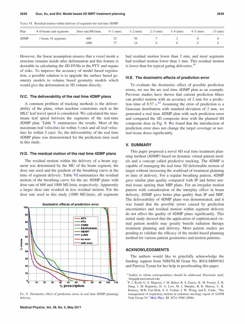
IV.E. The dosimetric effects of prediction error
To evaluate the dosimetric effect of possible prediction
errors, we use the arc real time 4DMP plan as an example.
Previous studies have shown that current prediction filters
can predict motion with an accuracy of 2 mm for a predic-
tion time of 0.57 s.42 Assuming the error of prediction is a
Gaussian distribution with standard deviation of 2 mm, we
generated a real time 4DMP plan with such prediction error
and compared the 4D composite dose with the planned 4D
composite dose in Fig. 9. We found that the introduction of
prediction error does not change the target coverage or nor-
mal tissue doses significantly.
V. SUMMARY
This paper proposed a novel 4D real time treatment plan-
ning method (4DMP) based on dynamic virtual patient mod-
els and a concept called predictive tracking. The 4DMP is
capable of managing the real time 3D deformable motion of
target without increasing the workload of treatment planning
or time of delivery. For a regular breathing pattern, 4DMP
gave similar plan quality compared with IP and better nor-
mal tissue sparing than MIP plans. For an irregular motion
pattern with consideration of the interplay effect in beam
delivery, 4DMP gave better plan quality than IP and MIP.
The deliverability of 4DMP plans was demonstrated, and it
was found that the possible errors caused by prediction
uncertainties and residual motion within segment delivery
do not affect the quality of 4DMP plans significantly. This
initial study showed that the application of sophisticated vir-
tual patient models may greatly benefit radiation therapy
treatment planning and delivery. More patient studies are
pending to validate the efficacy of the model-based planning
method for various patient geometries and motion patterns.
ACKNOWLEDGMENTS
The authors would like to gratefully acknowledge the
funding support from NIH/NLM Grant No. R01LM009362
and Patricia Tynan for her help in proofreading this paper.
a)Author to whom correspondence should be addressed. Electronic mail:
[email protected]. J. Keall, G. S. Mageras, J. M. Balter, R. S. Emery, K. M. Forster, S. B.
Jiang, J. M. Kapatoes, D. A. Low, M. J. Murphy, B. R. Murray, C. R.
Ramsey, M.B. Van Herk, S. S. Vedam, J. W. Wong, and E. Yorke, “The
management of respiratory motion in radiation oncology report of AAPM
Task Group 76,” Med. Phys. 33, 3874–3900 (2006).
TABLE VI. Residual motion within delivery of segments for real time 4DMP.
Plan # of beams and segments Dose rate/MU/min 0–1 (mm) 1–2 (mm) 2–3 (mm) 3–4 (mm) 4–5 (mm) >5 (mm)
4DMP 1 beam, 91 segments 600 32 50 7 2 0 0
1000 77 14 0 0 0 0
FIG. 9. Dosimetric effect of prediction errors in real time 4DMP planning/
delivery.
2649 Guo, Xu, and Shi: Model based 4D IMRT treatment planning 2649
Medical Physics, Vol. 38, No. 5, May 2011

2M. J. Murphy, “Tracking moving organs in real time,” Semin. Radiat.
Oncol. 14, 91–100 (2004).3S. Webb, “The effect on IMRT conformality of elastic tissue movement
and a practical suggestion for movement compensation via the modified
dynamic multileaf collimator (dMLC) technique,” Phys. Med. Biol. 50,
1163–1190 (2005).4L. Papieza, “DMLC leaf-pair optimal control of IMRT delivery for a mov-
ing rigid target,” Med. Phys. 31, 2742–2754 (2004).5D. McQuaid and S. Webb, “IMRT delivery to a moving target by dynamic
MLC tracking: Delivery for targets moving in two dimensions in the
beam’s eye view,” Phys. Med. Biol. 51, 4819–4839 (2006).6D. McQuaid, M. Partridge, J. R. Symonds-Tayler, P. M. Evans, and
S. Webb, “Target-tracking deliveries on an Elekta linac: A feasibility
study,” Phys. Med. Biol. 54, 3563–3578 (2009).7R. George, Y. Suh, M. Murphy, J. Williamson, E. Weiss, and P. Keall,
“On the accuracy of a moving average algorithm for target tracking during
radiation therapy treatment delivery,” Med. Phys. 35, 2356–2365 (2008).8T. Neicu, H. Shirato, Y. Seppenwoolde, and S. B. Jiang, “Synchronized
moving aperture radiation therapy (SMART): average tumour trajectory
for lung patients,” Phys. Med. Biol. 48, 587–598 (2003).9Y. Suh, A. Sawant, R. Venkat, and P. J. Keall, “Four-dimensional IMRT
treatment planning using a DMLC motion-tracking algorithm,” Phys.
Med. Biol. 54, 3821–3835 (2009).10Y. Liang, H. Xu, J. Yao, Z. Li, and W. Chen, “Four-dimensional intensity-
modulated radiotherapy planning for dynamic multileaf collimator track-
ing radiotherapy,” Int. J. Radiat. Oncol., Biol., Phys. 74, 266–274 (2009).11The dimensionality of the tumor motion was in reference to the beam
direction and the motion of DMLC leaves. 1D: tumor moves parallel to
the DMLC leaf motion; 2D: tumor moves both parallel and perpendicular
to the DMLC leaf motion in the beam’s eye view (BEV); 3D: tumor
moves in all three directions.12P. J. Keall, S. Joshi, S. S. Vedam, J. V. Siebers, V. R. Kini, and R. Mohan,
“Four-dimensional radiotherapy planning for DMLC-based respiratory
motion tracking,” Med. Phys. 32, 942–951 (2005).13G. D. Hugo, J. Liang, J. Campbell, and D. Yan, “On-line target position
localization in the presence of respiration: a comparison of two methods,”
Int. J. Radiat. Oncol., Biol., Phys. 69, 1634–1641 (2007).14D. Ruan, J. A. Fessler, J. M. Balter, and J. J. Sonke, “Exploring breathing
pattern irregularity with projection-based method,” Med. Phys. 33, 2491–
2499 (2006).15D. Ruan, J. A. Fessler, J. M. Balter, and P. J. Keall, “Real-time profiling of
respiratory motion: Baseline drift, frequency variation and fundamental
pattern change,” Phys. Med. Biol. 54, 4777–4792 (2009).16S. Vedam, A. Docef, M. Fix, M. Murphy, and P. Keall, “Dosimetric
impact of geometric errors due to respiratory motion prediction on
dynamic multileaf collimator-based four-dimensional radiation delivery,”
Med. Phys. 32, 1607–1620 (2005).17D. Ruan, J. A. Fessler, and J. M. Balter, “Real-time prediction of respira-
tory motion based on local regression methods,” Phys. Med. Biol. 52,
7137–7152 (2007).18D. Ruan and P. Keall, “Online prediction of respiratory motion: Multidi-
mensional processing with low-dimensional feature learning,” Phys. Med.
Biol. 55, 3011–3025 (2010).19C. Ozhasoglu, C. B. Saw, H. Chen, S. Burton, K. Komanduri, N. J. Yue, S.
M. Huq, and D. E. Heron, “Synchrony–cyberknife respiratory compensa-
tion technology,” Med. Dosim. 33, 117–123 (2008).20A. Sawant, R. Venkat, V. Srivastava, D. Carlson, S. Povzner, H. Cattell,
and P. Keall, “Management of three-dimensional intrafraction motion
through real-time DMLC tracking,” Med. Phys. 35, 2050–2061 (2008).21A. Sawant, R. L. Smith, R. B. Venkat, L. Santanam, B. Cho, P. Poulsen,
H. Cattell, L. J. Newell, P. Parikh, and P. J. Keall, “Toward submillimeter
accuracy in the management of intrafraction motion: the integration of
real-time internal position monitoring and multileaf collimator target
tracking,” Int. J. Radiat. Oncol., Biol., Phys. 74, 575–582 (2009).22B. Y. Yi, S. Han-Oh, F. Lerma, B. L. Berman, and C. Yu, “Real-time tu-
mor tracking with preprogrammed dynamic multileaf-collimator motion
and adaptive dose-rate regulation,” Med. Phys. 35, 3955–3962 (2008).23D. A. Low, P. J. Parikh, W. Lu, J. F. Dempsey, S. H. Wahab, J. P.
Hubenschmidt, M. M. Nystrom, M. Handoko, and J. D. Bradley, “Novel
breathing motion model for radiotherapy,” Int. J. Radiat. Oncol., Biol.,
Phys. 63, 921–929 (2005).24D. Yang, W. Lu, D. A. Low, J. O. Deasy, A. J. Hope, and I. El Naqa, “4D-
CT motion estimation using deformable image registration and 5D respira-
tory motion modeling,” Med. Phys. 35, 4577–4590 (2008).25K. K. Brock, S. J. Hollister, L. A. Dawson, and J. M. Balter, “Technical
note: Creating a four-dimensional model of the liver using finite element
analysis,” Med. Phys. 29, 1403–1405 (2002).26J. M. Hensel, C. Menard, P. W. Chung, M. F. Milosevic, A. Kirilova, J. L.
Moseley, M. A. Haider, and K. K. Brock, “Development of multiorgan fi-
nite element-based prostate deformation model enabling registration of
endorectal coil magnetic resonance imaging for radiotherapy planning,”
Int. J. Radiat. Oncol., Biol., Phys. 68, 1522–1528 (2007).27T. N. Nguyen, J. L. Moseley, L. A. Dawson, D. A. Jaffray, and K. K.
Brock, “Adapting population liver motion models for individualized
online image-guided therapy,” Conference Proceedings IEEE Engineeringin Medicine and Biology Society (EMBS 20th Annual International Con-
ference of the IEEE, Vancouver, Canada, 2008), pp. 3945–3948.28T. N. Nguyen, J. L. Moseley, L. A. Dawson, D. A. Jaffray, and K. K.
Brock, “Adapting liver motion models using a navigator channel
technique,” Med. Phys. 36, 1061–1073 (2009).29J. Eom, G. X. Xu, S. De, and C. Shi, “Predictive modeling of lung motion
over the entire respiratory cycle using measured pressure-volume data,
4DCT images and finite-element analysis,” Med. Phys. 37, 4389–4400
(2010).30Q. Zhang, A. Pevsner, A. Hertanto, Y. C. Hu, K. E. Rosenzweig, C. C.
Ling, and G. S. Mageras, “A patient-specific respiratory model of anatomi-
cal motion for radiation treatment planning,” Med. Phys. 34, 4772–4781
(2007).31J. Zhang, G. X. Xu, C. Shi, and M. Fuss, “Development of a geometry-
based respiratory motion-simulating patient model for radiation treatment
dosimetry,” J. Appl. Clin. Med. Phys. 9, 2700 (2008).32R. Colgan, J. McClelland, D. McQuaid, P. M. Evans, D. Hawkes, J. Brock,
D. Landau, and S. Webb, “Planning lung radiotherapy using 4D CT data
and a motion model,” Phys. Med. Biol. 53, 5815–5830 (2008).33R. McGurk, J. Seco, M. Riboldi, J. Wolfgang, P. Segars, and H. Paganetti,
“Extension of the NCAT phantom for the investigation of intra-fraction re-
spiratory motion in IMRT using 4D Monte Carlo,” Phys. Med. Biol. 55,
1475–1490 (2010).34R. W. Underberg, F. J. Lagerwaard, B. J. Slotman, J. P. Cuijpers, and S.
Senan, “Use of maximum intensity projections (MIP) for target volume
generation in 4DCT scans for lung cancer,” Int. J. Radiat. Oncol., Biol.,
Phys. 63, 253–260 (2005).35http://www.mathworks.com/.36E. E. Ahunbay, C. Peng, G. P. Chen, S. Narayanan, C. Yu, C. Lawton, and
X. A. Li, “An on-line replanning scheme for interfractional variations,”
Med. Phys. 35, 3607–3615 (2008).37Y. Feng, C. Castro-Pareja, R. Shekhar, and C. Yu, “Direct aperture defor-
mation: An interfraction image guidance strategy,” Med. Phys. 33, 4490–
4498 (2006).38Z. Gao, D. Wilkins, L. Eapen, C. Morash, Y. Wassef, and L. Gerig, “A
study of prostate delineation referenced against a gold standard created
from the visible human data,” Radiother. Oncol. 85, 239–246 (2007).39J. D. Hoisak, K. E. Sixel, R. Tirona, P. C. Cheung, and J. P. Pignol,
“Correlation of lung tumor motion with external surrogate indicators of
respiration,” Int. J. Radiat. Oncol., Biol. Phys. 60, 1298–1306 (2004).40D. P. Gierga, J. Brewer, G. C. Sharp, M. Betke, C. G. Willett, and G. T.
Chen, “The correlation between internal and external markers for abdomi-
nal tumors: implications for respiratory gating,” Int. J. Radiat. Oncol.,
Biol., Phys. 61, 1551–1558 (2005).41R. George, T. D. Chung, S. S. Vedam, V. Ramakrishnan, R. Mohan, E.
Weiss, and P. J. Keall, “Audio-visual biofeedback for respiratory-gated
radiotherapy: Impact of audio instruction and audio-visual biofeedback on
respiratory-gated radiotherapy,” Int. J. Radiat. Oncol., Biol., Phys. 65,
924–933 (2006).42P. R. Poulsen, B. Cho, D. Ruan, A. Sawant, and P. J. Keall, “Dynamic
multileaf collimator tracking of respiratory target motion based on a single
kilovoltage imager during arc radiotherapy,” Int. J. Radiat. Oncol., Biol.,
Phys. 77, 600–607 (2010).
2650 Guo, Xu, and Shi: Model based 4D IMRT treatment planning 2650
Medical Physics, Vol. 38, No. 5, May 2011