RDS: The Radio Data System - IZ3MEZ - The Radio Data... · Library of Congress...
353
RDS: The Radio Data System
Transcript of RDS: The Radio Data System - IZ3MEZ - The Radio Data... · Library of Congress...

RDS: The Radio Data System
RDS: The Radio Data System
Dietmar KopitzBev Marks
Artech HouseBoston • London
Library of Congress Cataloging-in-Publication DataKopitz, Dietmar.
RDS : the radio data system / Dietmar Kopitz, Bev Marks.p. cm.
Includes bibliographical references and index.ISBN 0-89006-744-9 (alk. paper)1. RDS (Radio) I. Marks, Bev. II. Title.
TK6570.R27K67 1998621.384’152—dc21 98-41083
CIP
British Library Cataloguing in Publication DataKopitz, Dietmar
RDS : the radio data system1. Radio - Packet transmissionI. Title II. Marks, Bev621.3’845
ISBN 0-89006-744-9
Cover design by Lynda Fishbourne
© 1999 EBU
All rights reserved. Printed and bound in the United States of America. No part of this bookmay be reproduced or utilized in any form or by any means, electronic or mechanical, includingphotocopying, recording, or by any information storage and retrieval system, without permis-sion in writing from the publisher.
All terms mentioned in this book that are known to be trademarks or service marks havebeen appropriately capitalized. Artech House cannot attest to the accuracy of this information.Use of a term in this book should not be regarded as affecting the validity of any trademark orservice mark.
International Standard Book Number: 0-89006-744-9Library of Congress Catalog Card Number: 98-41083
10 9 8 7 6 5 4 3 2 1
Contents
Foreword xvii
Acknowledgments xix
1 RDS System and Applications Overview 1
1.1 Introduction 1
1.2 Objectives to be Achieved With RDS 1
1.3 Historical Development 2
1.4 Evolution of the RDS Standards 10
1.4.1 Europe 10
1.4.2 United States 21
1.5 System Maintenance and Promotion 22
1.5.1 RDS Forum: a Worldwide Association of RDSUsers 23
1.5.2 The United States: NAB and EIA/CEMA 23
1.6 Usage of RDS Worldwide 25
1.6.1 Europe 25
1.6.2 The Special Case of Central and East EuropeanCountries 26
1.6.3 United States/Canada/Mexico 26
v
1.6.4 Other Countries 27
1.7 System Characteristics 28
1.7.1 Choice of Modulation Parameters 28
1.7.2 Choice of Baseband Coding 30
1.7.3 Message Format and Addressing 31
1.8 Applications of RDS 31
1.9 Data Capacity Impact on Applications 34
1.10 System Performance and Reliability 35
References 36
2 Differences Between RDS and RBDS 39
2.1 Introduction 39
2.2 The RDS Component Within RBDS 39
2.3 Details About the Differences 43
2.3.1 Programme TYpe (PTY) Definitions 43
2.3.2 Programme Identification (PI) Coding 45
2.3.3 Programme Service (PS) name 46
2.3.4 Fast PS Acquisition: Phased Out 47
2.3.5 Optional Multiplexing of RDS and MMBS:Offset Word E 47
2.3.6 Optional ID Logic Feature 49
2.3.7 Optional ODA Emergency Alert System 49
2.3.8 Option for Adding an AM Radio Data System 49
2.3.9 Location/Navigation Information Deleted 50
2.4 Use of the RDS Logos 50
2.5 Conclusions 51
References 53
3 RDS Features Serving as Tuning Aids 55
3.1 Introduction 55
3.2 Basic RDS Features 55
vi RDS: The Radio Data System

3.3 Programme Identification—PI 56
3.3.1 Broadcasting Conventions 59
3.3.2 Reception 61
3.4 Programme Service (PS) name 62
3.5 Alternative Frequency list—AF 64
3.6 Traffic Programme (TP) flag 67
3.7 Slow Labelling Codes 69
3.7.1 Extended Country Code (ECC) 69
3.7.2 Language Code 71
References 72
4 Radio Programme-Related RDS Features 73
4.1 Introduction 73
4.2 Programme TYpe (PTY) 74
4.2.1 PTY-SEARCH Mode 79
4.2.2 PTY-SELECTION Mode 79
4.2.3 PTY-STANDBY Mode 79
4.2.4 PTY-STORE Mode 80
4.2.5 PTY-ALARM Function and Testing 80
4.3 Programme TYpe Name (PTYN) 80
4.4 RadioText (RT) 81
4.5 Decoder Identification (DI) and Programme TYpeIdentification (PTYI) 85
4.6 Programme Item Number (PIN) 89
References 91
5 Additional Information Features 93
5.1 Introduction 93
5.2 Clock Time (CT) 93
5.3 Enhanced Other Networks (EON) 96
5.3.1 Alternative Frequency Information 98
Contents vii

5.3.2 PIN and PTY Information 99
5.3.3 PS Information 99
5.3.4 TP/TA Information 101
5.4 In-House (IH) and Transparent Data Channel(TDC) 101
5.5 Emergency Warning System (EWS) 101
References 104
6 Traffic Information Services 107
6.1 Introduction 107
6.2 RDS Traffic Services: Using the TP/TA Features 107
6.3 RDS Traffic Services: Using the EON and TP/TAFeatures 109
6.3.1 A Traffic Event Scenario 109
6.3.2 Clever Signalling 113
6.3.3 Update Messages Content 113
6.3.4 Receiver Reactions 114
References 115
7 Intelligent Transport Systems and RDS-TMC 117
7.1 Introduction 117
7.2 Strategic and Policy Issues 118
7.3 Market Trends for Telematics TerminalEquipment 118
7.4 Safety Aspects of Presentation of Traffic andTravel Information in Moving Vehicles 121
7.5 RDS-TMC 122
7.5.1 Objectives to be Achieved 122
7.5.2 History of the RDS-TMC Development 122
7.5.3 The Pan-European Service Objective and theMemoranda of Understanding 124
viii RDS: The Radio Data System

7.5.4 Institutional Challenges of RDS-TMC ServiceProvision 125
7.5.5 RDS-TMC Standards 130
7.5.6 Data Formats of the TMC Feature 132
7.5.7 Principles of RDS-TMC Event Coding 137
7.5.8 Principles of RDS-TMC Location ReferenceCoding 139
7.5.9 Example for Constructing an RDS-TMC Message 143
7.5.10 RDS Encoders and the EBU/UECP 143
7.5.11 RDS-TMC Receivers 147
7.6 Alternative Technologies 154
7.6.1 GSM 154
7.6.2 DARC (also previously known as SWIFT) 159
7.6.3 DAB Delivery of TMC Messages 161
7.7 The Longer Term Future of TMC 162
7.8 Other Examples for Using RDS in TransportTelematics 164
7.9 Conclusions 165
References 165
8 Basic and Enhanced Radio Paging 169
8.1 Introduction 169
8.2 What Can be Achieved With Radio Paging? 169
8.3 RDS Paging Operational Infrastructure 173
8.4 Paging Receivers 175
8.5 Future Developments 176
8.6 Conclusions 176
References 177
9 Open Data Applications (ODA) 179
9.1 Introduction 179
9.2 The Concept and Availability of the ODA Feature 179
Contents ix
9.3 Indicating an ODA Transmission 180
9.4 The Group Structure of Open Data Applications 183
9.5 Registration of an Open Data Application 186
9.6 Guidelines for Using ODA 187
10 Differential GPS 189
10.1 Introduction 189
10.2 Positioning With GPS 189
10.3 The Principle of Differential Correction 191
10.4 The RTCM DGPS Correction Format 192
10.4.1 Introduction 192
10.4.2 Required Data Elements 193
10.5 How RDS can be Used for Differential GPS 195
10.5.1 Design Considerations 195
10.5.2 Service Examples 196
10.6 Other Alternatives 199
10.6.1 Maritime Radio Beacons 199
10.6.2 AMDS 199
10.6.3 DARC 200
10.7 GLONASS: the Alternative to GPS 200
10.8 EGNOS: the European Component of GNSS 200
References 200
11 RDS Encoder Communication Protocols andthe UECP 203
11.1 Introduction 203
11.2 Why RDS Encoders Need a CommunicationProtocol 203
11.3 Why the EBU and Encoder ManufacturersDeveloped the UECP 205
11.4 The UECP Concept 206
11.4.1 Addressing Method 206
x RDS: The Radio Data System
11.4.2 RDS Encoder Conceptual Model 208
11.4.3 UECP Transmission Modes 211
11.4.4 UECP Protocol Description 211
References 215
12 RDS Demodulators and Decoders 217
12.1 Introduction 217
12.2 General Principles 217
12.2.1 RDS Demodulator/Decoder Technique andFunctionality 217
12.2.2 Principles of the RDS Block SynchronisationSystem 220
12.2.3 Error Correction and/or Detection 223
12.3 RDS Integrated Circuits and Chip Sets 224
12.4 Consumer Receivers 225
12.4.1 Car Radios 225
12.4.2 Home Hi-Fi 225
12.4.3 Portable Radios 225
12.5 Radios on Plug-In Cards for Personal Computers 226
12.5.1 The Philips SMART Radio 226
12.5.2 ADS Radio Rock-It RDS 228
12.5.3 The GEWI Radio G211 and TMC OfficeDecoder 229
12.6 RDS Data Monitors and Analysers for PCS 229
12.6.1 General Remarks 229
12.6.2 AUDITEM AUDEMAT Rx_MCRDS 230
12.6.3 AZTEC FM Explorer Version 3.0 230
12.6.4 The RDS Software Decoder Version 2.0 fromFranken-Team 232
12.6.5 Schümperlin’s PRD-3 and PRDLIB16.DLL 233
References 234
Contents xi
13 Outlook: RDS and Other Broadcast DataSystems for Radio 235
13.1 Introduction 235
13.2 LF, MF, and HF Broadcasting 235
13.2.1 AM Data System 235
13.2.2 New Developments Using Digital Modulation 237
13.3 FM Broadcasting 237
13.3.1 The Future of RDS 237
13.3.2 High-Speed Data Systems 239
13.4 Digital Radio DAB 242
13.4.1 Origins and Possible Evolution 242
13.4.2 Comparison of RDS and DAB Data Features 243
13.4.3 RDS/DAB Interoperability 245
13.5 Digital Radio by Satellite 246
References 247
Appendix A: Modulation of the RDS Data Signal 249
A.1 Subcarrier Frequency 249
A.2 Subcarrier Phase 249
A.3 Subcarrier Level 252
A.4 Method of Modulation 252
A.5 Clock-Frequency and Data Rate 252
A.6 Differential Coding 252
A.7 Data Channel Spectrum Shaping 253
References 257
Appendix B: RDS Data Decoding 259
B.1 Introduction 259
B.2 Baseband Coding Structure 259
B.3 Order of Bit Transmission, Error Protection,and Synchronisation Information 260
xii RDS: The Radio Data System
B.4 Message Format and Addressing of Groups 263
References 265
Appendix C: RDS Reception Reliability 267
C.1 Introduction 267
C.2 Bit Error Rate 267
C.3 Block Error Rate 269
C.4 Error Rates for RDS Messages 269
C.5 RDS Coverage Area 271
References 272
Appendix D: Required Data Repetition Ratesfor Programme-Related RDS Features 273
References 275
Appendix E: RDS Data TransmissionCapacity Limits 277
E.1 Introduction 277
E.2 Calculation of RDS Capacity 277
E.3 Analysis of RDS Capacity 278
E.3.1 Grouping of Different Features 278
E 3.2 Discussion on the Analysis 278
E.4 Conclusion About RDS Capacity 281
References 282
Appendix F: PI Coding in RDS and RBDS 283
F.1 Introduction 283
F.2 Programme Identification Code Structure 283
F.2.1 Country Identification 284
F.2.2 Coverage Area Codes 284
F.2.3 Programme Reference Number 285
F.3 PI Coding Rules for North America 286
F.3.1 Basic Principles 286
Contents xiii
F.3.2 Call Letter Conversion Method 287
References 288
Appendix G: RDS Country or AreaIdentification Codes 289
G.1 Introduction 289
G.2 PI Code Structure 290
G.3 Extended Country Codes 290
G.4 Allocated Country/Area Symbols 290
G.4.1 Allocation of Symbols for Countries in ITURegion 1 290
G.4.2 Allocations of Symbols for Countries in ITURegion 2 295
G.4.3 Allocations of Symbols for Countries in ITURegion 3 297
References 299
Appendix H: PTY Display Terms in SeveralDifferent Languages 301
H.1 Introduction 301
References 307
Appendix I: Character Sets for AlphanumericDisplay 309
References 312
Appendix J: Implemented RDSFeatures in Various Countries 313
J.1 Introduction 313
Appendix K: Web Site of the RDS Forum 317
Appendix L: UECP Message Commands 319
L.1 Introduction 319
L.2 Command Format 319
xiv RDS: The Radio Data System

L.3 Examples of Specific Messages 320
L.3.1 Message to Set the PTY Code 320
L.3.2 Message to Set the PS name 320
L.4 Listing of All Possible UECP Version 5.1Message Commands 321
L.4.1 RDS Message Commands 321
L.4.2 Open Data Application Commands 322
L.4.3 Transparent Data Commands 322
L.4.4 Paging Commands 322
L.4.5 Clock Setting and Control 323
L.4.6 RDS Adjustment and Control 323
L.4.7 ARI Adjustment and Control 323
L.4.8 Control and Setup Commands 323
L.4.9 Bidirectional Commands (Remote andConfiguration Commands) 324
L.4.10 Specific Message Commands 324
References 324
Appendix M: Glossary and Abbreviations 325
M.1 Glossary 325
M.1.1 Alternative Frequencies (AF) list 325
M.1.2 Clock Time (CT) and date 325
M.1.3 Decoder Identification (DI) and Dynamic PTYIndicator (PTYI) 326
M.1.4 Extended Country Code (ECC) 326
M.1.5 Enhanced Other Networks (EON) information 326
M.1.6 Emergency Warning System (EWS) 326
M.1.7 In-House applications (IH) 326
M.1.8 Music Speech Switch (MS) 327
M.1.9 Open Data Applications (ODA) 327
M.1.10 Programme Identification (PI) 327
Contents xv
M.1.11 Programme Item Number (PIN) 327
M.1.12 Programme Service (PS) name 328
M.1.13 Programme TYpe (PTY) 328
M.1.14 Programme TYpe Name (PTYN) 328
M.1.15 Radio Paging (RP) 328
M.1.16 RadioText (RT) 329
M.1.17 Traffic Announcement (TA) flag 329
M.1.18 Transparent Data Channels (TDC) 329
M.1.19 Traffic Message Channel (TMC) 329
M.1.20 Traffic Programme (TP) flag 329
M.2 Additional Definitions 330
M.2.1 Broadcaster 330
M.2.2 Programme Service Provider 330
M.2.3 Data Service Provider 331
M.2.4 Transmission Operator 331
M.2.5 Network Operator 331
M.3 Abbreviations 331
M.4 Acronyms 333
References 338
About the Authors 339
Index 341
xvi RDS: The Radio Data System
Foreword
RDS was developed as a result of the far sighted preparatory studies undertakenwithin EBU Technical Groups over 20 years ago. The system was designed tofulfill the requirements of all European countries and it subsequently became aEuropean standard under the umbrella of CENELEC. In many countries RDSservices were rapidly introduced with the aim of generally improving FM radioand especially mobile reception. New data services, in particular for traffic andtravel information, were added and are now being introduced. RDS has beenfurther developed to permit migration to Digital Radio which has even morepowerful features built upon that experience already gained.
In recent years, the European-developed RDS has also become a globalsuccess. In the United States, RDS was first adapted to meet North Americanrequirements, then the RDS Forum, with its worldwide viewpoint, stressed theneed for converging standards. This was recently achieved by joint activity inEurope and in the United States, culminating in upgraded, harmonised stan-dards for RDS in Europe and RBDS in the United States.
It is recognised that FM radio will still exist for many years to come. So,in the future the EBU will continue to support the maintenance of the RDSstandard. But of course, one day Digital Radio will deliver much more power-ful data services, a process started many years before by RDS.
The authors, Dietmar Kopitz and Bev Marks, have accompanied thedevelopment of RDS from the very earliest days. They are now highly active inthe related domain of increasing importance to broadcasters—the provision ofradio data services specifically for traffic and travel information.
xvii

I wish this book a great success and I hope that it will also stimulate manynew initiatives for further implementations of RDS all around the world.
Professor Albert Scharf
xviii RDS: The Radio Data System

Acknowledgments
In the European Broadcasting Union, many working groups have contributedto the elaboration of the Radio Data System, since the early nineteen seventies.We have had the privilege and pleasure to work with these groups for manyyears. As a result, we both enjoy long lasting friendships with many highlygifted personalities who have contributed so much to the success story thatRDS has already become, with over 50 million RDS radios in use.
Much of the content of this book is based on shared knowledge gainedduring the multinational development work to which many people from othercountries have contributed. We cannot individually mention everyone, how-ever, we would like to list the most significant contributors and express ourappreciation to them for their contributions given to RDS. These individualshave made RDS internationally successful through standardisation in Europe.We are also pleased to acknowledge the support of their organisations orcompanies.
• Josef Berger (Österreichischer Rundfunk), Austria
• Kari Ilmonen (Yleisradio), Finland
• Martti Saarelma (Yleisradio), Finland
• André Keller (TéléDiffusion de France), France
• Michel Rigal (TéléDiffusion de France), France
• Philippe Meillan (TéléDiffusion de France), France
• Hermann Eden (Institut für Rundfunktechnik), Germany
• Jürgen Mielke (Institut für Rundfunktechnik), Germany
xix
• Karl-Heinz Schwaiger (Institut für Rundfunktechnik), Germany
• Mario Cominetti (Radiotelevisione Italiana), Italy
• Henri van der Heide (Nederlandse Omroep Stichting), Netherlands
• Theo Kamalski (Philips Car Systems), Netherlands
• Sten Bergman (Sveriges Radio), Sweden
• Tore Karlsson (Televerket), Sweden
• Østen Mäkitalo (Televerket), Sweden
• Christer Odmalm (Televerket), Sweden
• Ernst Schwarz (Swiss PTT), Switzerland
• Johnny Beerling (British Broadcasting Corporation), United Kingdom
• Stan M. Edwardson (British Broadcasting Corporation), United Kingdom
• Bob (S R) Ely (British Broadcasting Corporation), United Kingdom
• Simon Parnall (British Broadcasting Corporation), United Kingdom
• Mark Saunders (British Broadcasting Corporation), United Kingdom
• Ian Collins (UK Independent Radio), United Kingdom
After the European RDS standard was established within CENELEC, anew standardisation activity started in the US National Radio Systems Com-mittee and an adaptation of RDS to the North American broadcast environ-ment resulted in the agreement of the EIA/NAB voluntary industry standard:RBDS. Again we would like to acknowledge the significant work of additionalNorth American contributors.
• Terry Beale (Delco Electronics)
• John D. Casey (Denon Electronics)
• Almon H. Clegg (Denon Nippon Columbia)
• Jerry LeBow (Sage Alert Systems)
• Thomas D. Mock (Electronic Industry Association)
• Dave Wilson (National Association of Broadcasters)
• Scott A.Wright (Delco Electronics)
We thank the EBU for the permission to use, for the purpose of thisbook, RDS material that has been elaborated over the years in our daily work.We are grateful to Philippe Juttens (EBU), for his intuitive understanding of
xx RDS: The Radio Data System

our needs, resulting in the high quality graphical design work for RDS that wehave regularly used in many EBU publications.
Our many contacts with members of the RDS Forum have given us muchhelp and inspiration, for which we are grateful.
We also thank our publisher Artech House and, in particular, JulieLancashire and John Walker, our editors, for their continuous encourage-ment to progress this project. We greatly appreciated their guidance during thedevelopment of the book concept which we conceived together for the mobilecommunications series.
We thank our book reviewer, Grant Klein for the excellent professionaladvice given to us during the writing of the manuscript. Susanna Taggartfrom Artech House has also given considerable and valuable help to us in thiscontext.
Finally, we thank our families and close friends for their long patiencewith us. Perhaps inevitably with such a subject, we significantly underesti-mated the time needed to accomplish the manuscript and they were alwayskindly forgiving when the writing of the book made us unavailable and tempo-rarily prevented us from enjoying life together. Now that all the hard work isdone, we hope that we will find many new opportunities together which willcompensate for the good times missed during the winter of 1997!
Dietmar Kopitz and Bev MarksGeneva (Switzerland) and Battle (England)
October 1998
Acknowledgments xxi
1RDS System and Applications Overview
1.1 Introduction
This chapter is conceived to give a good and detailed overview about the RadioData System (RDS) and its origins, and does not require too much technicalknowledge from the reader about mobile data communication techniques.It provides much of the necessary background that will help readers to betterunderstand the details given about RDS and its implementation options in theremainder of this book.
1.2 Objectives to be Achieved With RDS
The Radio Data System offers broadcasters a flexible data transmission channelaccompanying their very high frequency/frequency modulation (VHF/FM)sound broadcasts. Additionally, RDS offers the possibility for data service pro-viders to introduce new data services if these are based on the concept of send-ing relatively few bits to many users. Thus, RDS can accommodate a widerange of possible implementation options.
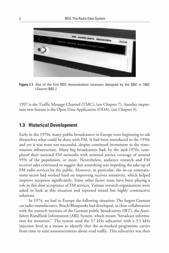
Following a long period of systems development in the 1970s and early1980s (see Figure 1.1), and field trials in several European countries, RDS isnow implemented all over Western Europe, in several Central and East Euro-pean countries, in some Asia Pacific region countries, in South Africa, and inthe United States (using the Radio Broadcast Data System (RBDS) standard),and is also used by some broadcasters in Latin America. One important newfeature for which regular services started in many European countries as of
1
1997 is the Traffic Message Channel (TMC), (see Chapter 7). Another impor-tant new feature is the Open Data Application (ODA), (see Chapter 9).
1.3 Historical Development
Early in the 1970s, many public broadcasters in Europe were beginning to askthemselves what could be done with FM. It had been introduced in the 1950sand yet it was none too successful, despite continued investment in the trans-mission infrastructure. Many big broadcasters had, by the mid-1970s, com-pleted their national FM networks with nominal service coverage of around95% of the population, or more. Nevertheless, audience research and FMreceiver sales continued to suggest that something was impeding the take-up ofFM radio services by the public. However, in particular, the in-car entertain-ment sector had worked hard on improving receiver sensitivity, which helpedimprove reception significantly. Some other factor must have been playing arole in this slow acceptance of FM services. Various research organisations wereasked to look at this situation and reported mixed but highly constructivesolutions.
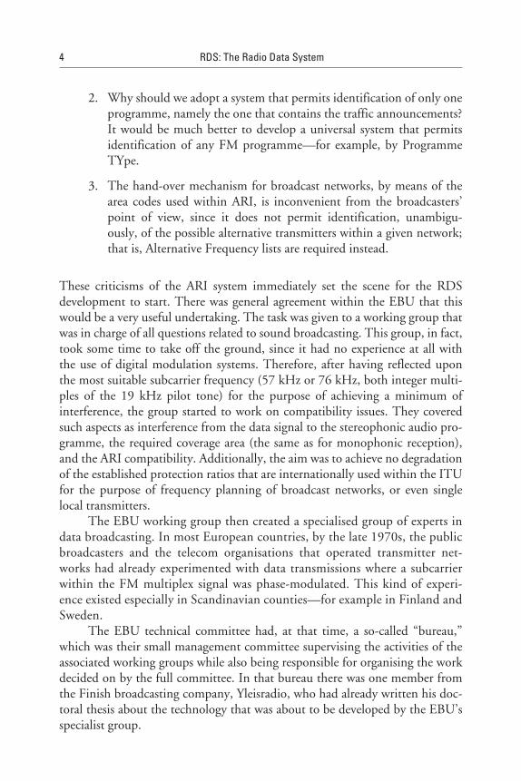
In 1974, we had in Europe the following situation: The largest Germancar radio manufacturer, Bosch/Blaupunkt had developed, in close collaborationwith the research institute of the German public broadcasters (IRT), the Auto-fahrer Rundfunk Information (ARI) System, which means “broadcast informa-tion for motorists.” The system used the 57 kHz subcarrier with a 3.5 kHzinjection level as a means to identify that the so-marked programme carriesfrom time to time announcements about road traffic. This subcarrier was then
2 RDS: The Radio Data System
Figure 1.1 One of the first RDS demonstration receivers designed by the BBC in 1982.(Source: BBC.)
amplitude-modulated with 125 Hz when the traffic announcement was broad-cast as a means of identifying that such an announcement was on-air. In addi-tion, one out of six possible signals (between 23.75 Hz and 53.98 Hz) was usedfor area identification.
Bosch/Blaupunkt was hopeful at that time that this ingenious systemwould be adopted by the broadcasters all over Europe, which would have beenan advantage from the receiver manufacturer’s point of view because of theconvenience of a more uniform market for the sale of car radios. To gainthe broadcasters’ support, the ARI system was submitted by the German publicbroadcasters to the European Broadcasting Union’s technical committee, withthe view of obtaining a recommendation from the EBU that this system be putinto general use all over Western Europe.
The EBU is a professional association of, at that time, mostly publicbroadcasters in Western Europe, but now also includes the broadcasters ofCentral and Eastern Europe. The EBU is in fact the authority to establish orharmonise operational broadcast practises in Europe. In doing so, there is fullawareness in the EBU that it is not a standardisation organisation. Therefore,the EBU collaborates very closely with standardisation organisations likethe International Telecommunication Union (ITU), Comité Européen deNormalisation Electrotechnique (CENELEC), and European Telecommunica-tions Standards Institute (ETSI) to create the necessary standards, normallybefore any recommendation relating to an operational practice for broadcastingis issued.
Although it was rather unexpected by those who undertook the initiativein the EBU—to recommend the ARI system for general introduction in1974—their motion launched the RDS development within the EBU. Why?In the EBU’s technical committee there was a great deal of disagreement aboutthe universal applicability of the ARI system. The broadcasting model used inGermany, and for which the ARI system was conceived, was in fact ratherexceptional. Instead of regional broadcasting companies, most countries usednational networks. Regionalisation, though quite useful for road traffic infor-mation, was not a common practise at that time. Also, for ARI it was assumedthat in each region there would only be one programme that contained broad-cast information for motorists. In reality, though, national broadcastersinserted these announcements in several of their programmes. Thus, within thetechnical committee of the EBU, in 1975, a number of provoking questionsand statements were being put forth, such as the following:
1. Would it not be better to seek to develop a system that uses digitalmodulation instead of the analogue AM used in ARI?
RDS System and Applications Overview 3
2. Why should we adopt a system that permits identification of only oneprogramme, namely the one that contains the traffic announcements?It would be much better to develop a universal system that permitsidentification of any FM programme—for example, by ProgrammeTYpe.
3. The hand-over mechanism for broadcast networks, by means of thearea codes used within ARI, is inconvenient from the broadcasters’point of view, since it does not permit identification, unambigu-ously, of the possible alternative transmitters within a given network;that is, Alternative Frequency lists are required instead.
These criticisms of the ARI system immediately set the scene for the RDSdevelopment to start. There was general agreement within the EBU that thiswould be a very useful undertaking. The task was given to a working group thatwas in charge of all questions related to sound broadcasting. This group, in fact,took some time to take off the ground, since it had no experience at all withthe use of digital modulation systems. Therefore, after having reflected uponthe most suitable subcarrier frequency (57 kHz or 76 kHz, both integer multi-ples of the 19 kHz pilot tone) for the purpose of achieving a minimum ofinterference, the group started to work on compatibility issues. They coveredsuch aspects as interference from the data signal to the stereophonic audio pro-gramme, the required coverage area (the same as for monophonic reception),and the ARI compatibility. Additionally, the aim was to achieve no degradationof the established protection ratios that are internationally used within the ITUfor the purpose of frequency planning of broadcast networks, or even singlelocal transmitters.
The EBU working group then created a specialised group of experts indata broadcasting. In most European countries, by the late 1970s, the publicbroadcasters and the telecom organisations that operated transmitter net-works had already experimented with data transmissions where a subcarrierwithin the FM multiplex signal was phase-modulated. This kind of experi-ence existed especially in Scandinavian counties—for example in Finland andSweden.
The EBU technical committee had, at that time, a so-called “bureau,”which was their small management committee supervising the activities of theassociated working groups while also being responsible for organising the workdecided on by the full committee. In that bureau there was one member fromthe Finish broadcasting company, Yleisradio, who had already written his doc-toral thesis about the technology that was about to be developed by the EBU’sspecialist group.
4 RDS: The Radio Data System
It is interesting to note, even from the present point of view, whatMr. K. Ilmonen’s thesis in 1971 was all about, and what kind of research workhe had then initiated within the technical department of Yleisradio. One of hiscollaborators had also joined the EBU specialist group and contributed to thework then being undertaken. Ilmonen’s thesis was about listener preferences forloudness in speech and music broadcasts when these occur at various sequencesin the same programme. To permit a separate adjustment of the volume andsome kind of automatic control function in broadcast operations and thereceiver, an identification of each speech or music item was suggested. If thiscould be done, one could also make an identification of the Programme TYpe.He then drew up a list that closely resembles those lists now used in RDS andDAB. He suggested using a 57 kHz subcarrier, amplitude-modulated by FSKfrequencies, to achieve the objective for such a universal identification system.Being in the EBU and the representative of a small country, Ilmonen insistedstrongly that Europe needed a standard for a unified system, thus giving a strongimpetus on the management level to conduct the work with this very importantobjective clearly in mind (see the historical document reproduced on page 6) [1].
How did the EBU specialists then proceed in their work? In 1976, therewere already several different radio data systems proposed from Finland, theNetherlands (see the historical document reproduced on page 6), and Sweden.The specialists tried to identify what these systems had in common. Theylooked at a form of coding of the data stream that would permit optimal per-formance in the mobile reception mode at typical car-travelling speeds and sub-ject to severe multipath interference, as would usually occur with FM inmountainous regions.
To determine these basic parameters, it was agreed to conduct a first fieldtrial in 1980 in the area of Bern/Interlaken, Switzerland. Representatives fromthe European receiver manufacturing industry (EUROTECH, now the Euro-pean Association of Consumer Electronics Manufacturers (EACEM)) wereinvited to join. A questionnaire was sent to broadcasters and industry leaders todetermine the desirable features of the upcoming system. The test data broad-cast in the region of Bern/Interlaken was then recorded by various researchlaboratories and analysed with the view of optimising the mobile reception.
In 1981, there was subsequent agreement of coordinated applications andthe principles to be used in baseband coding. Test transmissions then started inseveral countries such as France, Finland, Germany, the Netherlands, Sweden,and the United Kingdom. Since the system parameters were not yet fullydefined, each country had designed its own particular radio data system, andsometimes one country even tested several different variants. Thus, by 1982eight different systems were already known and it became an imminent task tobring the choice straight down to one [2–6].
RDS System and Applications Overview 5
6 RDS: The Radio Data System
Two historical EBU documents on emerging RDSNOS Hilversum, Netherlands:Some basic proposals for the development of a programme identification system in Band IIOn the 14 of October 1975 delegates from IRT Hamburg, NV Philips Eindhoven and NOS were in Hilversumto discuss theproblems concerning the realisation of a transmitter and programme code in the FM band.
A summary of the meeting is given in this document.....FM transmitters can be modulated with frequencies up to 100 kHz. Within this frequency range two smallbands can be pointed out for extra information. One of them is just around 57 kHz and is used by the GermanyARI system. Unfortunately no extra information can be modulated upon the carrier of 57 kHz.
The second frequency range is around 67 kHz, about 65-69 kHz and is used by the SCA system. This systemis not in use in Europe.....The transmitter and programme code could be transmitted in a digital form. A practical type of modulationcould be the frequency shift keying system, shifting from i.e. 66-68 kHz.
Due to the low modulation depth, the signal to noise ratio within this channel will be fairly low. Probably thesystem is not suitable for a car or a portable radio.
1. Programme identification 4 characters2. FM channel number 3 characters3. Place name of the transmitter tower 5 characters4. Kind of programme 2 characters
Use could be made of the ASCI code. The whole information should be given five times per second.The type of display is still under study.
Fields tests in the near future will give information how far the system could disturb the radio programmeand how far the system can be disturbed by man made noise.
H.J. v.d. Heide, NOS
th
Information that could be transmitted:
****
Oy. YLEISRADIO Ab. Helsinki, January 23 , 1976
Dear Mr Kopitz,....With the present state of art, a radio listener meets several situations of inconvenience in connectionwith the listening. Firstly, almost everywhere more than one programme are receivable simultaneouslyon VHF, and it is not always convenient for the listener to know whether he is tuned to the rightprogramme. Secondly, a programme is often transmitted by several VHF transmitters, a number of whichare receivable at the listener’s place. To find the transmitters with the strongest signal is not easy, wouldhowever be useful. Thirdly, listeners waiting for a certain programme item to start (say, the news),frequently wish to ignore the preceding programme, which results in an inconvenience: keeping aconstant watch on the run of time. And, finally, research has shown that different programmes arewanted with different characteristics of reproduction, the most widely known differences being thatbetween speech and music, or between music of different type.
By transmission of a suitable programme information signal together with the programme signal proper,all the above inconvenience could be avoided. Receivers could be developed to perform in fact any kindof changes in the listening characteristics: to find a certain programme (including the search for a trafficradio transmitter), to find a programme of a given type (including traffic programmes) to switch on at theright time, to give each programme a given level or a given setting of treble and bass, combination ofloudspeakers, etc.....For the further development of the programme identification system, we are at present constructing aprototype transmitter and receiver, with the aim of demonstrating to our receiver industry the scope ofpossibilities such a system could give for the listener-consumer. We have chosen 57 kHz as sub-carrier,amplitude modulated by FSK frequencies. The code chosen allows for transmission of 1024 alternativesof programme identification. The complete data sequence consists of 12 bits.
We have heard that similar developments are going on in research laboratories of some receivermanufacturers. In order to avoid a marketing of receivers with different characteristics, we very stronglyconsider it of paramount importance to standardise the identification codes. This, according to ouropinion, is to a great extent a task for the receiver industry. However, the system (especially if the code islarge) will affect the possibility of using e.g. the band 53-75 kHz of VHF transmitters to any other purposes(SCA, tetraphony, the temporary EBU traffic-VHF systems, etc.). Thus, the EBU andCCIR should also investigate the problem.
rd
The Finnish Broadcasting Company Ltd.
Dr. Kari Ilmonen
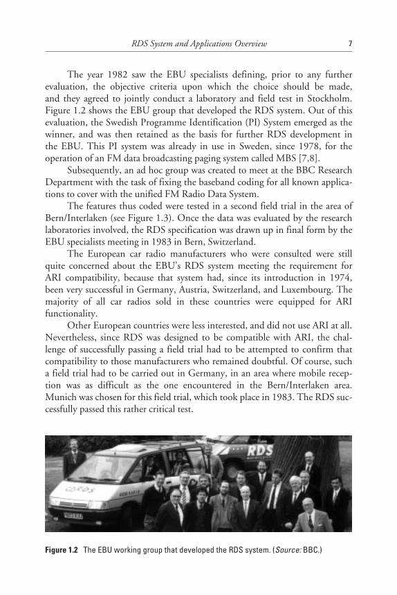
The year 1982 saw the EBU specialists defining, prior to any furtherevaluation, the objective criteria upon which the choice should be made,and they agreed to jointly conduct a laboratory and field test in Stockholm.Figure 1.2 shows the EBU group that developed the RDS system. Out of thisevaluation, the Swedish Programme Identification (PI) System emerged as thewinner, and was then retained as the basis for further RDS development inthe EBU. This PI system was already in use in Sweden, since 1978, for theoperation of an FM data broadcasting paging system called MBS [7,8].
Subsequently, an ad hoc group was created to meet at the BBC ResearchDepartment with the task of fixing the baseband coding for all known applica-tions to cover with the unified FM Radio Data System.
The features thus coded were tested in a second field trial in the area ofBern/Interlaken (see Figure 1.3). Once the data was evaluated by the researchlaboratories involved, the RDS specification was drawn up in final form by theEBU specialists meeting in 1983 in Bern, Switzerland.
The European car radio manufacturers who were consulted were stillquite concerned about the EBU’s RDS system meeting the requirement forARI compatibility, because that system had, since its introduction in 1974,been very successful in Germany, Austria, Switzerland, and Luxembourg. Themajority of all car radios sold in these countries were equipped for ARIfunctionality.
Other European countries were less interested, and did not use ARI at all.Nevertheless, since RDS was designed to be compatible with ARI, the chal-lenge of successfully passing a field trial had to be attempted to confirm thatcompatibility to those manufacturers who remained doubtful. Of course, sucha field trial had to be carried out in Germany, in an area where mobile recep-tion was as difficult as the one encountered in the Bern/Interlaken area.Munich was chosen for this field trial, which took place in 1983. The RDS suc-cessfully passed this rather critical test.
RDS System and Applications Overview 7
Figure 1.2 The EBU working group that developed the RDS system. (Source: BBC.)
As a consequence, the RDS specification was adopted by the EBU andEUROTECH in 1983-84, published, and also submitted to the ITU andCCIR Study Group 10. This study group extracted the essential characteristicsfrom the EBU specification and transcribed them to a new CCIR Recommen-dation 643, which was then adopted in 1986 [9].
All the above shows clearly how RDS has emerged over time and betweenthe years 1975-1984. In retrospect, during this 10-year period we saw the fol-lowing occur:
1. The desire to universally identify each Frequency Modulation (FM)programme; this created the PI and Programme Service (PS) features.
2. The desire to identify broadcasts for motorists more universally thanARI; this created the Traffic Programme (TP) and Traffic Announce-ment (TA) features.
3. The desire to hand over a mobile receiver within a network; this cre-ated the Alternative Frequencies (AF) feature.
4. The desire to identify speech and music and programme types; thiscreated the Music Speech (MS) and Programme Type (PTY) feature.
5. The desire to maintain radio paging within the data broadcast as itwas already implemented in Sweden; this created the Radio Paging(RP) feature.
8 RDS: The Radio Data System
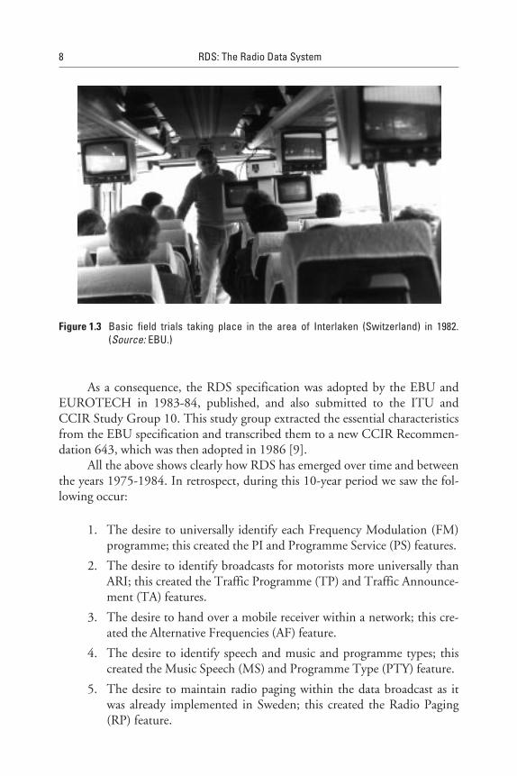
Figure 1.3 Basic field trials taking place in the area of Interlaken (Switzerland) in 1982.(Source: EBU.)
A system was now designed and available for the mobile listener, who hadneeded help with in-car reception of FM for the various reasons already estab-lished by audience research; namely, automatic retuning from one transmissioncoverage area to the next area and so on. The system also provided an emula-tion of the ARI system used in Austria, Germany, Luxembourg, and Switzer-land that alerted drivers to traffic announcements. Many other features wereproposed and built into the RDS system to be dynamically multiplexed asneeded in each transmission. The key mechanisms were designed for mobilereception and a group/block data format to ensure very fast data synchronisa-tion and decoding of certain features, while allowing some features to be con-veyed at a slow rate for general information. Since the system design wasdeveloped by broadcasters working in the well-regulated environment of the1970s, a number of features were considered but not fully developed at thattime. However, their far-reaching decisions regarding future enhancements hasallowed RDS to mature over the years.
In 1985, EUROTECH agreed with the EBU about the general introduc-tion of RDS and promised, on the condition that the EBU would give theirsupport towards the development of the RDS-Traffic Message Channel(RDS-TMC) feature (see Chapter 7), that the first RDS receivers would be pre-sented at the international consumer electronics show, IFA’87, in Berlin. From1988 on, these receivers would be marketed in all those countries where RDSwas already introduced.
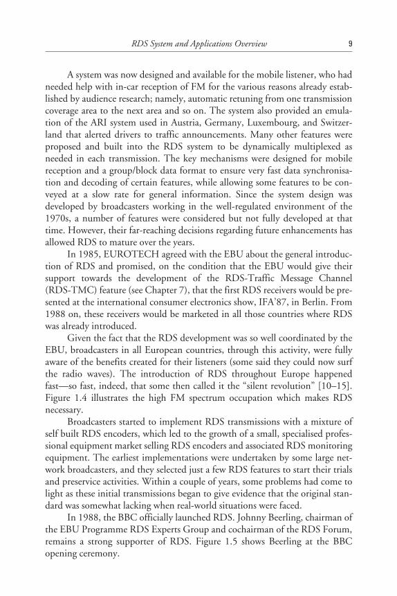
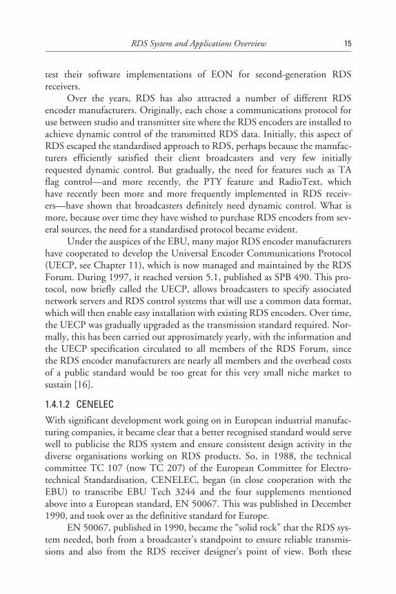
Given the fact that the RDS development was so well coordinated by theEBU, broadcasters in all European countries, through this activity, were fullyaware of the benefits created for their listeners (some said they could now surfthe radio waves). The introduction of RDS throughout Europe happenedfast—so fast, indeed, that some then called it the “silent revolution” [10–15].Figure 1.4 illustrates the high FM spectrum occupation which makes RDSnecessary.
Broadcasters started to implement RDS transmissions with a mixture ofself built RDS encoders, which led to the growth of a small, specialised profes-sional equipment market selling RDS encoders and associated RDS monitoringequipment. The earliest implementations were undertaken by some large net-work broadcasters, and they selected just a few RDS features to start their trialsand preservice activities. Within a couple of years, some problems had come tolight as these initial transmissions began to give evidence that the original stan-dard was somewhat lacking when real-world situations were faced.
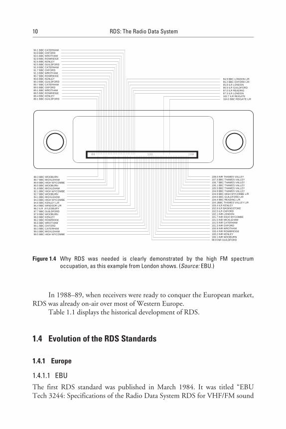
In 1988, the BBC officially launched RDS. Johnny Beerling, chairman ofthe EBU Programme RDS Experts Group and cochairman of the RDS Forum,remains a strong supporter of RDS. Figure 1.5 shows Beerling at the BBCopening ceremony.
RDS System and Applications Overview 9
In 1988–89, when receivers were ready to conquer the European market,RDS was already on-air over most of Western Europe.
Table 1.1 displays the historical development of RDS.
1.4 Evolution of the RDS Standards
1.4.1 Europe
1.4.1.1 EBUThe first RDS standard was published in March 1984. It was titled “EBUTech 3244: Specifications of the Radio Data System RDS for VHF/FM sound
10 RDS: The Radio Data System
94.1 BBC CATERHAM93.9 BBC OXFORD93.5 BBC WROTHAM92.9 BBC ROWRIDGE92.6 BBC KENLEY92.5 BBC GUILDFORD91.9 BBC CATERHAM91.7 BBC OXFORD91.3 BBC WROTHAM90.7 BBC ROWRIDGE90.6 BBC KENLEY90.3 BBC GUILDFORD89.7 BBC CATERHAM89.5 BBC OXFORD89.1 BBC WROTHAM88.5 BBC ROWRIDGE88.4 BBC KENLEY88.1 BBC GUILDFORD
88.3 BBC WOOBURN89.7 BBC MICKLEHAM89.9 BBC HIGH WYCOMBE90.5 BBC WOOBURN91.9 BBC MICKLEHAM92.1 BBC HIGH WYCOMBE92.7 BBC WOOBURN94.1 BBC MICKLEHAM94.3 BBC HIGH WYCOMBE94.6 BBC KENLEY L/R95.4 BBC WINDSOR L/R96.2 ILR AYLESBURY97.7 BBC GUILDFORD97.9 BBC WOOBURN 96.0 BBC KENLEY96.2 BBC ROWRIDGE96.6 BBC WROTHAM99.1 BBC OXFORD99.3 BBC CATERHAM99.3 BBC MICKLEHAM99.5 BBC HIGH WYCOMBE
108.0 INR THAMES VALLEY107.3 BBC THAMES VALLEY106.7 BBC THAMES VALLEY106.1 BBC THAMES VALLEY105.5 BBC THAMES VALLEY104.9 BBC THAMES VALLEY104.9 BBC HIGH WYCOMBE L/R104.6 BBC GUILDFORD L/R104.4 BBC READING L/R104.1BBC THAMES VALLEY L/R103.4 ILR KENLEY102.9 ILR BASINGSTOKE102.5 ILR OXFORD102.1 INR LONDON101.7 INR HIGH WYCOMBE101.5 INR MICKLEHAM101.5 INR CATERHAM101.3 INR OXFORD100.9 INR WROTHAM100.4 INR ROWBRIDGE100.2 INR KENLEY100.1 INR WOOBURN99.9 INR GUILDFORD
94.9 BBC LONDON L/R95.2 BBC OXFORD L/R95.8 ILR LONDON96.9 ILR GUILDFORD97.0 ILR READING97.3 ILR LONDON102.7 ILR REIGATE104.0 BBC REIGATE L/R
100 10888
Figure 1.4 Why RDS was needed is clearly demonstrated by the high FM spectrumoccupation, as this example from London shows. (Source: EBU.)
RDS System and Applications Overview 11
Table 1.1History of RDS Development
1975 Pre-development start
1980 First field trial at Bern/Interlaken, Switzerland
1982 Test start in Stockholm, SwedenEvaluation of eight systems in Helsinki, FinlandRDS baseband coding agreedSecond field trial at Bern/Interlaken
1983 Industry/broadcasters meeting at EBUJoint industry/broadcaster field trial in Munich, GermanyRDS adopted by EBU and industry—submitted to CCIR
1984 First presentation of RDS in Detroit, MI, USAFord starts RDS car radio development in DetroitRDS specification EBU 3244 published
1985 Large scale pre-operational trial in GermanyEBU recommends RDS introductionIndustry/broadcasters agree first receivers target from 1987
1986 First presentation of RDS at NAB Dallas, TX, USRDS CCIR Recommendation published
1987 Ireland, France and Sweden introduce RDSFirst RDS receivers shown at IFA Berlin, GermanyVolvo markets the world’s first RDS car radio
Figure 1.5 Johnny Beerling at the BBC opening ceremony in 1988. (Source: BBC.)
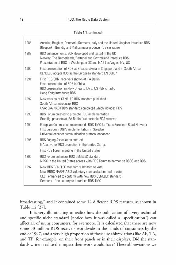
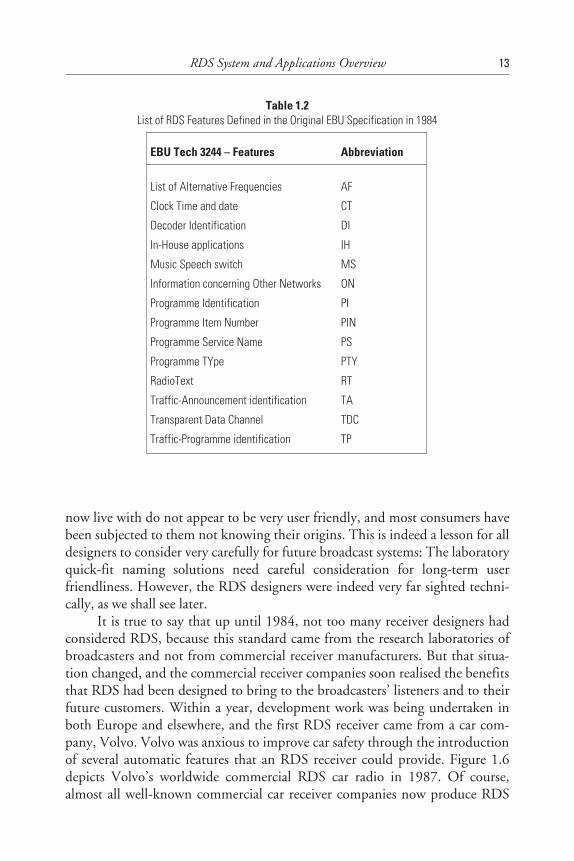
broadcasting,” and it contained some 14 different RDS features, as shown inTable 1.2 [27].
It is very illuminating to realise how the publication of a very technicaland specific niche standard (notice how it was called a “specification”) canaffect all of us, as consumers, for evermore. It is calculated that there are nowsome 50 million RDS receivers worldwide in the hands of consumers by theend of 1997, and a very high proportion of those use abbreviations like AF, TA,and TP, for example, on their front panels or in their displays. Did the stan-dards writers realise the impact their work would have? These abbreviations we
12 RDS: The Radio Data System
Table 1.1 (continued)
1988 Austria , Belgium, Denmark, Germany, Italy and the United Kingdom introduce RDSBlaupunkt, Grundig and Philips mass produce RDS car radios
1989 RDS enhancements: EON developed and tested in the UKNorway, The Netherlands, Portugal and Switzerland introduce RDSPresentation of RDS in Washington DC and NAB Las Vegas, NV, US
1990 First presentation of RDS at BroadcastAsia in Singapore and in South AfricaCENELEC adopts RDS as the European standard EN 50067
1991 First RDS-EON receivers shown at IFA BerlinFirst presentation of RDS in ChinaRDS presentation in New Orleans, LA to US Public RadioHong Kong introduces RDS
1992 New version of CENELEC RDS standard publishedSouth Africa introduces RDSUSA: EIA/NAB RBDS standard completed which includes RDS
1993 RDS Forum created to promote RDS implementationGrundig: presents at IFA Berlin first portable RDS receiver
1994 European Commission recommends RDS-TMC for Trans-European Road NetworkFirst European DGPS implementation in SwedenUniversal encoder communication protocol enhanced
1995 RDS Paging Association createdEIA activates RDS promotion in the United States
First RDS Forum meeting in the United States
1996 RDS Forum enhances RDS CENELEC standardNRSC in the United States agrees with RDS Forum to harmonize RBDS and RDS
1997 New RDS CENELEC standard submitted to voteNew RBDS NAB/EIA US voluntary standard submitted to voteUECP enhanced to conform with new RDS CENELEC standardGermany - first country to introduce RDS-TMC
now live with do not appear to be very user friendly, and most consumers havebeen subjected to them not knowing their origins. This is indeed a lesson for alldesigners to consider very carefully for future broadcast systems: The laboratoryquick-fit naming solutions need careful consideration for long-term userfriendliness. However, the RDS designers were indeed very far sighted techni-cally, as we shall see later.
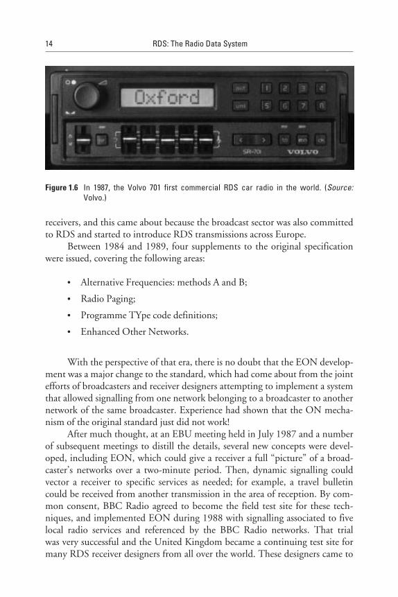
It is true to say that up until 1984, not too many receiver designers hadconsidered RDS, because this standard came from the research laboratories ofbroadcasters and not from commercial receiver manufacturers. But that situa-tion changed, and the commercial receiver companies soon realised the benefitsthat RDS had been designed to bring to the broadcasters’ listeners and to theirfuture customers. Within a year, development work was being undertaken inboth Europe and elsewhere, and the first RDS receiver came from a car com-pany, Volvo. Volvo was anxious to improve car safety through the introductionof several automatic features that an RDS receiver could provide. Figure 1.6depicts Volvo’s worldwide commercial RDS car radio in 1987. Of course,almost all well-known commercial car receiver companies now produce RDS
RDS System and Applications Overview 13
Table 1.2List of RDS Features Defined in the Original EBU Specification in 1984
EBU Tech 3244 – Features Abbreviation
List of Alternative Frequencies AF
Clock Time and date CT
Decoder Identification DI
In-House applications IH
Music Speech switch MS
Information concerning Other Networks ON
Programme Identification PI
Programme Item Number PIN
Programme Service Name PS
Programme TYpe PTY
RadioText RT
Traffic-Announcement identification TA
Transparent Data Channel TDC
Traffic-Programme identification TP
receivers, and this came about because the broadcast sector was also committedto RDS and started to introduce RDS transmissions across Europe.
Between 1984 and 1989, four supplements to the original specificationwere issued, covering the following areas:
• Alternative Frequencies: methods A and B;
• Radio Paging;
• Programme TYpe code definitions;
• Enhanced Other Networks.
With the perspective of that era, there is no doubt that the EON develop-ment was a major change to the standard, which had come about from the jointefforts of broadcasters and receiver designers attempting to implement a systemthat allowed signalling from one network belonging to a broadcaster to anothernetwork of the same broadcaster. Experience had shown that the ON mecha-nism of the original standard just did not work!
After much thought, at an EBU meeting held in July 1987 and a numberof subsequent meetings to distill the details, several new concepts were devel-oped, including EON, which could give a receiver a full “picture” of a broad-caster’s networks over a two-minute period. Then, dynamic signalling couldvector a receiver to specific services as needed; for example, a travel bulletincould be received from another transmission in the area of reception. By com-mon consent, BBC Radio agreed to become the field test site for these tech-niques, and implemented EON during 1988 with signalling associated to fivelocal radio services and referenced by the BBC Radio networks. That trialwas very successful and the United Kingdom became a continuing test site formany RDS receiver designers from all over the world. These designers came to
14 RDS: The Radio Data System
Figure 1.6 In 1987, the Volvo 701 first commercial RDS car radio in the world. (Source:Volvo.)
test their software implementations of EON for second-generation RDSreceivers.
Over the years, RDS has also attracted a number of different RDSencoder manufacturers. Originally, each chose a communications protocol foruse between studio and transmitter site where the RDS encoders are installed toachieve dynamic control of the transmitted RDS data. Initially, this aspect ofRDS escaped the standardised approach to RDS, perhaps because the manufac-turers efficiently satisfied their client broadcasters and very few initiallyrequested dynamic control. But gradually, the need for features such as TAflag control—and more recently, the PTY feature and RadioText, whichhave recently been more and more frequently implemented in RDS receiv-ers—have shown that broadcasters definitely need dynamic control. What ismore, because over time they have wished to purchase RDS encoders from sev-eral sources, the need for a standardised protocol became evident.
Under the auspices of the EBU, many major RDS encoder manufacturershave cooperated to develop the Universal Encoder Communications Protocol(UECP, see Chapter 11), which is now managed and maintained by the RDSForum. During 1997, it reached version 5.1, published as SPB 490. This pro-tocol, now briefly called the UECP, allows broadcasters to specify associatednetwork servers and RDS control systems that will use a common data format,which will then enable easy installation with existing RDS encoders. Over time,the UECP was gradually upgraded as the transmission standard required. Nor-mally, this has been carried out approximately yearly, with the information andthe UECP specification circulated to all members of the RDS Forum, sincethe RDS encoder manufacturers are nearly all members and the overhead costsof a public standard would be too great for this very small niche market tosustain [16].
1.4.1.2 CENELECWith significant development work going on in European industrial manufac-turing companies, it became clear that a better recognised standard would servewell to publicise the RDS system and ensure consistent design activity in thediverse organisations working on RDS products. So, in 1988, the technicalcommittee TC 107 (now TC 207) of the European Committee for Electro-technical Standardisation, CENELEC, began (in close cooperation with theEBU) to transcribe EBU Tech 3244 and the four supplements mentionedabove into a European standard, EN 50067. This was published in December1990, and took over as the definitive standard for Europe.
EN 50067, published in 1990, became the “solid rock” that the RDS sys-tem needed, both from a broadcaster’s standpoint to ensure reliable transmis-sions and also from the RDS receiver designer’s point of view. Both these
RDS System and Applications Overview 15
parties required the RDS standard to link them together and give each the cer-tainty that RDS would indeed give the radio user the assistance that RDS hadpromised nearly 10 years before.
So, here was the first significant demonstration that the original develop-ment of the RDS specification had been given future-proofing, as the addi-tional features in the four supplements could be added quite easily and allowcontinued development of both the transmission equipment and RDSreceivers.
Nevertheless, standards also require stability to allow development time,and the issue of EN 50067:1990, with endorsement from both the broadcastand the manufacturing sectors, promised this time in the future. But, of course,Europe could not now keep RDS to itself. Already some broadcasters fromother parts of the world had noticed what RDS could do. Notably, broadcastersin two very diverse countries—Hong Kong and South Africa—started to nego-tiate for RDS technology. They were prepared to invest in RDS to eventuallypromote the technology to both their customers (the listeners) and to the RDSreceiver suppliers. In the absence of a worldwide standard for RDS they natu-rally opted for RDS implementations using EN 50067:1990, especially becausethe consumer manufacturers could only offer products manufactured for thatstandard. In both of these cases, the broadcasters had similar structures to thosealready found in Europe, so the RDS standard requirements fit their networkswell and virtually no adaptation was forced upon them.
If a standard has been well designed, additions to it will offer enhance-ments that the industry and the consumer alike will want. However, the timingof such enhancements has to be considered carefully to ensure that the revisedstandard does not destabilise the marketplace. Accordingly, the EBU issuedSPB 482, which proposed certain enhancements to EN 50067:1990. Theseenhancements were made to clarify, to a greater level of detail, certain codingissues that had become necessary. That work was ready for the next issue of thestandard and completed well in advance of the marketplace actually needingthe items that were standardised. This was to prove valuable in the develop-ments that were taking place in the United States. In effect, parallel discussionproceeded over the next 24 months or so, and EN 50067:1992 was issued inApril of that year. It just missed the work of another small EBU group who haddeveloped PI codes and extended country code (ECC) proposals for the world-wide implementation of RDS, and their output was published in August 1992by the EBU as SPB 485 (revised in 1992) covering allocation of country/areaidentification codes in RDS [17,18].
In the meantime, CENELEC EN 50067:1992 has been much upgraded.The new revised text, which was first published in September 1996 byCENELEC, was prepared by the RDS Forum in close collaboration with the
16 RDS: The Radio Data System
CENELEC technical committee 207 with full involvement of experts fromthe EBU. Certain elements of text were revised in accordance with experiencegained from the RDS system and changes in broadcasting practise since the ini-tial specification was published. An interesting example are the new clausesrelating to the PS feature.
The Open Data Application (ODA) has been added as a new feature topermit a flexible extension of RDS to still undefined applications. Further-more, cross-references were made to the Comité Européen de Normalisation(CEN) standards, defining the RDS-TMC feature.
Receivers produced in accordance with the new specification will, ofcourse, be compatible with RDS broadcasts, which conform to previous edi-tions of the RDS specification.
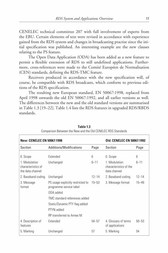
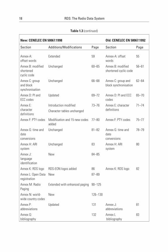
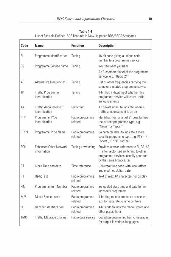
The resulting new European standard, EN 50067:1998, replaced fromApril 1998 onwards the old EN 50067:1992, and all earlier versions as well.The differences between the new and the old standard versions are summarisedin Table 1.3 [19–22]. Table 1.4 lists the RDS features in upgraded RDS/RBDSstandards.
RDS System and Applications Overview 17
Table 1.3Comparison Between the New and the Old CENELEC RDS Standards
New: CENELEC EN 50067:1998 Old: CENELEC EN 50067:1992
Section Additions/Modifications Page Section Page
0. Scope Extended 6 0. Scope 6
1. Modulationcharacteristics ofthe data channel
Unchanged 6–11 1. Modulationcharacteristics of thedata channel
6–11
2. Baseband coding Unchanged 12–14 2. Baseband coding 12–14
3. Messageformat
PS usage explicitly restricted toprogramme service label
ODA added
TMC standard references added
Static/Dynamic PTY flag added
PTYN added
RP transferred to Annex M
15–53 3. Message format 15–49
4. Description offeatures
Extended 54–57 4. Glossary of termsof applications
50–53
5. Marking Unchanged 57 5. Marking 54
18 RDS: The Radio Data System
Table 1.3 (continued)
New: CENELEC EN 50067:1998 Old: CENELEC EN 50067:1992
Section Additions/Modifications Page Section Page
Annex-A:offset words
Extended 59 Annex-A: offsetwords
55
Annex B: modifiedshortenedcyclic code
Unchanged 60–65 Annex B: modifiedshortened cyclic code
56–61
Annex C: groupand blocksynchronisation
Unchanged 66–68 Annex C: group andblock synchronisation
62–64
Annex D: PI andECC codes
Updated 69–72 Annex D: PI and ECCcodes
65–70
Annex E:characterdefinitions
Introduction modified
Character tables unchanged
73–76 Annex E: characterdefinitions
71–74
Annex F: PTY codes Modification and 15 new codesadded
77–80 Annex F: PTY codes 75–77
Annex G: time anddateconversions
Unchanged 81–82 Annex G: time anddateconversions
78–79
Annex H: ARIsystem
Unchanged 83 Annex H: ARIsystem
80
Annex J:languageidentification
New 84–85
Annex K: RDS logo RDS-EON logos added 86 Annex K: RDS logo 82
Annex L: Open Dataregistration
New 87–89
Annex M: RadioPaging
Extended with enhanced paging 90–125
Annex N: world-wide country codes
New 126–130
Annex P:abbreviations
Updated 131 Annex J:abbreviations
81
Annex Q:bibliography
132 Annex Lbibliography
83
RDS System and Applications Overview 19
Table 1.4List of Possible Defined RDS Features in New Upgraded RDS/RBDS Standards
Code Name Function Description
PI Programme Identification Tuning 16-bit code giving a unique serialnumber to a programme service
PS Programme Service name Tuning You see what you hear
An 8-character label of the programmeservice, e.g. “Radio 21”
AF Alternative Frequencies Tuning List of other frequencies carrying thesame or a related programme service
TP Traffic Programmeidentification
Tuning 1-bit flag indicating of whether thisprogramme service will carry trafficannouncements
TA Traffic Announcementidentification
Switching An on/off signal to indicate when atraffic announcement is on air
PTY Programme TYpeidentification
Radio programmerelated
Identifies from a list of 31 possibilitiesthe current programme type, e.g.“News” or “Sport”
PTYN Programme TYpe Name Radio programmerelated
8-character label to indicate a morespecific programme type, e.g. PTY = 4:“Sport”, PTYN: “Football”
EON Enhanced Other Networkinformation
Tuning / switching Provides a cross-reference to PI, PS, AF,PTY for vectorised switching to otherprogramme services, usually operatedby the same broadcaster
CT Clock Time and date Time reference Universal time code with local offsetand modified Julian date
RT RadioText Radio programmerelated
Text of max. 64 characters for display
PIN Programme Item Number Radio programmerelated
Scheduled start time and date for anindividual programme
M/S Music Speech code Radio programmerelated
1-bit flag to indicate music or speech,e.g. for separate volume controls
DI Decoder Identification Radio programmerelated
4-bit code to indicate mono, stereo andother possibilities
TMC Traffic Message Channel Radio data service Coded predetermined traffic messagesfor output in various languages
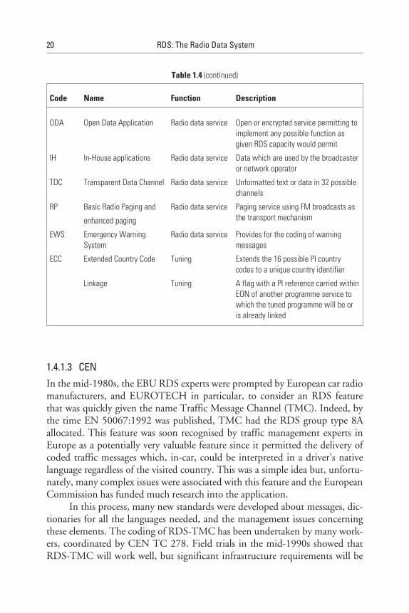
1.4.1.3 CENIn the mid-1980s, the EBU RDS experts were prompted by European car radiomanufacturers, and EUROTECH in particular, to consider an RDS featurethat was quickly given the name Traffic Message Channel (TMC). Indeed, bythe time EN 50067:1992 was published, TMC had the RDS group type 8Aallocated. This feature was soon recognised by traffic management experts inEurope as a potentially very valuable feature since it permitted the delivery ofcoded traffic messages which, in-car, could be interpreted in a driver’s nativelanguage regardless of the visited country. This was a simple idea but, unfortu-nately, many complex issues were associated with this feature and the EuropeanCommission has funded much research into the application.
In this process, many new standards were developed about messages, dic-tionaries for all the languages needed, and the management issues concerningthese elements. The coding of RDS-TMC has been undertaken by many work-ers, coordinated by CEN TC 278. Field trials in the mid-1990s showed thatRDS-TMC will work well, but significant infrastructure requirements will be
20 RDS: The Radio Data System
Table 1.4 (continued)
Code Name Function Description
ODA Open Data Application Radio data service Open or encrypted service permitting toimplement any possible function asgiven RDS capacity would permit
IH In-House applications Radio data service Data which are used by the broadcasteror network operator
TDC Transparent Data Channel Radio data service Unformatted text or data in 32 possiblechannels
RP Basic Radio Paging and
enhanced paging
Radio data service Paging service using FM broadcasts asthe transport mechanism
EWS Emergency WarningSystem
Radio data service Provides for the coding of warningmessages
ECC Extended Country Code Tuning Extends the 16 possible PI countrycodes to a unique country identifier
Linkage Tuning A flag with a PI reference carried withinEON of another programme service towhich the tuned programme will be oris already linked

needed to implement RDS-TMC fully across Europe, and this phase is nowjust beginning. Chapter 7 deals with all these issues in much more detail.
1.4.2 United States
In 1990, discussions started about standardising RDS for the United Statesunder the auspices of the National Association of Broadcasters (NAB), and theNational Radio Standards Committee (NRSC) was asked to form a subcom-mittee to report on the possibilities.
In the U.S. radio environment, radio networks and relay transmitters, ortransposers as they are called in the United States, are more infrequently found,which is quite different from Europe. So, RDS clearly needed some adaptation.But the NRSC subcommittee, which had elected to call the American standard“Radio Broadcast Data System (RBDS),” realised that RDS would be morequickly implemented in the United States if core aspects of both systems wereshared, because RDS knowledge, RDS encoders, and RDS receivers were allreadily available. Indeed, the subcommittee that worked on RBDS standardisa-tion even wished for as much harmonisation as they could achieve.
Apart from a few new features, the RBDS standard required specialinterpretation of two of the existing features. Firstly, the PI code structure ofEN 50067:1990 was unsuited to the different regulation of radio stations in theUnited States, where “call letters” are the only centralised data that can be reliedupon. Thus, a clever algorithm was developed to allow conversion of call lettersinto a unique PI code so that existing RDS encoders and RDS receivers coulduse this PI code without any problem. The reason for this approach was thatone wanted to avoid the need for a federal organisation to be charged withadministering PI codes for RBDS implementation. Secondly, the U.S.-specificprogramme format of radio stations needed a new list of PTY codes since PTYcodes for Europe were quite inappropriate. Thus, a different set of PTY codeswas developed for the United States. The other significant demonstration wasthat RDS could largely be compatibly upgraded as time progressed and newideas were required.
Generally, it was thought that RDS receivers could now be used any-where in the world, provided the ECC feature was used to uniquely designate acountry. The original RDS specification had only considered countries thatwere members of the EBU; now, expansion to the whole world became a dis-tinct necessity.
In the United States, the RBDS specification was adopted in January1993 as a voluntary national standard, jointly issued by the EIA and the NAB.As explained above, this standard includes as its major component the RDS
RDS System and Applications Overview 21
system, and European receivers could easily be modified for use in the UnitedStates. In the large majority of cases, they would even work well unmodified,especially with the five basic features: PI, PS, AF, TP and TA [23].
The differences between RBDS and RDS are explained in greater detail inChapter 2. Simultaneously, as the European RDS standard was upgraded in theyears 1995–97, an upgraded RBDS specification was completed by the end of1997 within the National Radio Systems Committee (NRSC), which is jointlysponsored by the Electronics Industry Association/Consumer ElectronicsManufacturers Association (EIA/CEMA) and the National Association ofBroadcasters (NAB) [24].
RBDS was now drawn up with the view to harmonise, to the largestextent possible, the RBDS specification with the RDS features most recentlyspecified in Europe in the EN 500067:1998.
In the United States since about 1995, RBDS is only the name for theAmerican standard. When implemented in receivers, the system has been calledRDS, as it is anywhere else in the world. RDS in the United States is identifiedwith the same logo as specified in the European CENELEC standard, which isthe same as was once developed for the EBU by the BBC.
1.5 System Maintenance and Promotion
While successful standards are in use by the few people who helped developthem, all is likely to be well because they know what they intended when draft-ing the documents! But once a wider group of users has a need for a standard,the intentions that are not specified fully or well, can be misunderstood or mis-interpreted. Furthermore, field experience of implementing standards tends tothrow up many new issues.
Recognising a need for more information about RDS, the EBU publishedthe document, “Tech 3260, Guidelines for the implementation of the RDS sys-tem,” which was intended to encapsulate and transfer some of that knowledgeto other workers in RDS technology before it was lost [25].
With all the developments that have taken place over recent years, it isnow necessary to prepare another edition of the RDS guidelines document, andthe RDS Forum proposes to undertake that work with the support of manyworkers in the RDS field. It will have a slightly differently focus as to imple-mentations and the system approach needed to achieve a full set of RDS serv-ices, including non-programme-related data services multiplexed with radioprogramme-related data services, and the commercial and technical issues asso-ciated with managing and billing in such a system.
22 RDS: The Radio Data System

1.5.1 RDS Forum: a Worldwide Association of RDS Users
The RDS Forum has existed since 1993. Membership is open to all profession-als involved in using RDS technology. The RDS Forum has held two plenarymeetings per year, and a large proportion of the more than 100 membersworldwide attend.
In 1997, the RDS Forum had four working groups concerned with main-taining the RDS standard, developing accepted guidelines for RDS systemoperation, upgrading the Universal Encoder Communications Protocol(UECP), and dealing with RDS/DAB cross-referencing together with theobjective of implementing plans for DAB transmissions and receivers that offera compatible user interface.
The operational expenses of the association are shared among all themembership. Members pay an annual fee for each registered representative.More detailed information about the RDS Forum is available on theInternet.
The Internet address for the RDS Forum Web site is: www.rds.org.uk.
1.5.2 The United States: NAB and EIA/CEMA
RDS is promoted in the United States through the National Association ofBroadcasters (NAB) and the Consumer Electronic Manufacturers Association(CEMA), a branch of the Electronics Industry Association (EIA). Both theNAB and CEMA organise very significant annual conventions, with a majortechnical exhibition where RDS technology is presented at various occasions.The EBU was also invited to participate in these presentations. In addition,both the NAB and CEMA participate in the RDS Forum, which is coordinatedby the EBU. Hence, there is a continuous exchange of experiences with regardto the implementation of RDS in Europe and the United States.
CEMA sponsored an RDS promotional effort in 1995–96. While thereare some 5,000 FM radio stations operating in the United States, after thatcampaign, 750 of them had RDS implemented. The campaign concentratedon the 26 metropolitan areas with the largest population in the United Statesand was aimed at raising the awareness of radio broadcasters about RDS. At thesame time, the NAB published a 98-page booklet explaining RDS applicationsto broadcasters [26].
One particular problem that existed at that time in the United States wasthat there were not many RDS receivers on the market, and therefore dealersand consumers were largely unaware of RDS and what benefits it could offer.In addition, many broadcast station owners were confused about RDS becausethe NAB was of the opinion that the United States needed a high-speed data
RDS System and Applications Overview 23
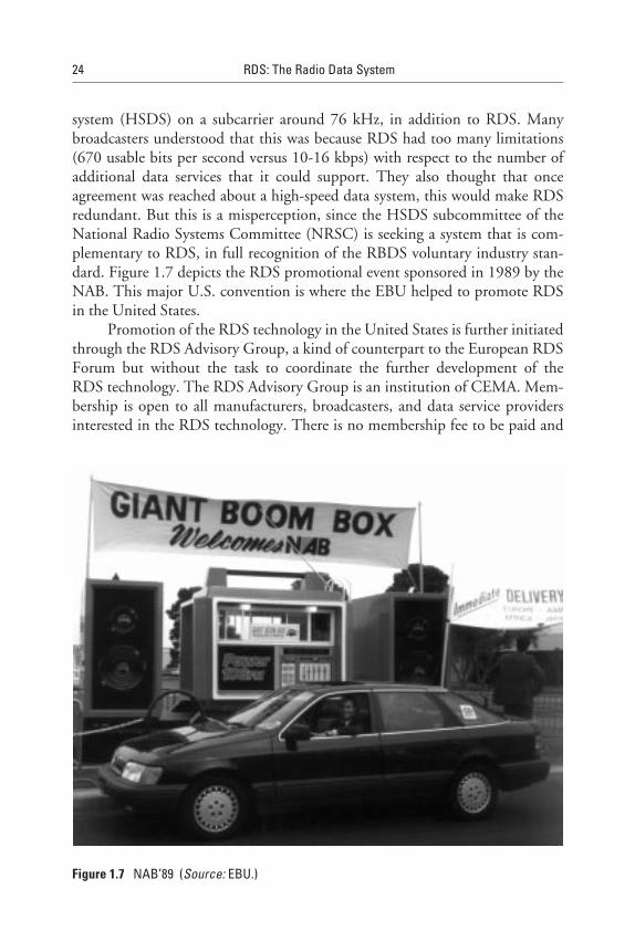
system (HSDS) on a subcarrier around 76 kHz, in addition to RDS. Manybroadcasters understood that this was because RDS had too many limitations(670 usable bits per second versus 10-16 kbps) with respect to the number ofadditional data services that it could support. They also thought that onceagreement was reached about a high-speed data system, this would make RDSredundant. But this is a misperception, since the HSDS subcommittee of theNational Radio Systems Committee (NRSC) is seeking a system that is com-plementary to RDS, in full recognition of the RBDS voluntary industry stan-dard. Figure 1.7 depicts the RDS promotional event sponsored in 1989 by theNAB. This major U.S. convention is where the EBU helped to promote RDSin the United States.
Promotion of the RDS technology in the United States is further initiatedthrough the RDS Advisory Group, a kind of counterpart to the European RDSForum but without the task to coordinate the further development of theRDS technology. The RDS Advisory Group is an institution of CEMA. Mem-bership is open to all manufacturers, broadcasters, and data service providersinterested in the RDS technology. There is no membership fee to be paid and
24 RDS: The Radio Data System
Figure 1.7 NAB’89 (Source: EBU.)

meetings take place during major conventions (on average, four times a year). Aquarterly newsletter distributed through CEMA and NAB provides updates onnew developments and products in the U.S. market. The activity is financedthrough voluntary contributions from interested consumer electronic manufac-turers. The companies that were most active in the years 1995–97 were Delco,Denon, and Pioneer.
The following Web sites provide more information and updates aboutRDS in the United States:
• CEMA: www.cemacity.org/rds/
• NAB: www.nab.org./SciTech/
1.6 Usage of RDS Worldwide
1.6.1 Europe
RDS is widely implemented in Europe. Details of the features used can befound in Appendix J.
At the end of 1997, the situation was generally as follows. The basic fea-tures PI, PS, and AF (and when applicable, TP and TA) are used by almost allnetworks and local stations in all countries. Initially, broadcasters using net-works had problems implementing radio programme-dependent RDS features,one reason being that there were generally no data links between the studiosand the RDS encoders on the transmitter sites that could be used to transportthe information.
Nowadays, this situation is changing. Audio links between the broadcast-ing house and the transmitters have become increasingly digital, and on theradio programme side, the new possibilities of digital radio and radio onthe Internet require the radio programme makers to turn their interesttowards the future and use the new multimedia. This creates ideal conditionsfor RDS to have dynamic PTY and RadioText (RT) implemented. The same isalso true for MS.
RDS-TMC, a new feature in 1997, is now being more widely used. Thedriving force behind this is the transport sector of the European Commissionand the European Conference of the Ministers of Transport (ECMT). Detailsabout its implementation are given in Chapter 7.
Radio paging (RP) via RDS is used in a number of European countries,but the increasing success of the Global System for Mobile Communications(GSM) mobile telephone services make this less and less interesting. France is
RDS System and Applications Overview 25
still the country where RDS Radio Paging (RP) is most important, but otherpockets of RP can be found elsewhere and are still developing.
The Emergency Warning System (EWS) was considered in a number ofEuropean countries, but a number of alternative technologies are already inplace, so this feature is generally not used. In the United States, there is a muchgreater interest in using this feature.
The Differential Global Positioning System (DGPS) via ODA is beingconsidered in a number of countries, and these services are already or will soonbe operational in Germany, Sweden, and the United Kingdom. However, thesystem specifications being used are not the same. In Germany, the service willbe open, and in the other countries, it is encrypted and a subscription isrequired by the end user.
1.6.2 The Special Case of Central and East European Countries
The RDS standard CENELEC EN 50067:1998 is restricted to FM BandII (87.5–108 MHz), but in Central and Eastern Europe, FM Band I(65–74 MHz) is also in use. In these countries, FM broadcasting occurs now inboth bands; formerly, it was in band I only. In principle, RDS would be feasi-ble in Band I as well, but the necessary AF codes are not defined—neither forBand I nor for any cross-referencing between bands I and II.
A decision was made in the RDS Forum not to provide further supportfor development of RDS for Band I. This was done to encourage the transfer ofradio services operating in Band I to Band II, with the view of harmonising theuse of band II for Eastern Europe in the same way as it is used in WesternEurope. It was also recommended by the RDS Forum that broadcastinginformation for motorists should only be implemented in Band II so thatRDS-TMC could then become available everywhere in Europe within the samefrequency band.
RDS is already used in a number of Central and Eastern European coun-tries, but nowhere yet is it generally implemented on all band II FM stations ornetworks. Often, the reason for using RDS is the desire to operate an RDSpaging service and/or a subscription service for DGPS; where this is the case,the basic RDS features required for tuning, such as PI, PS, and AF, are alsoimplemented.
1.6.3 United States/Canada/Mexico
The people involved in the making of the RBDS standard for the United Statesgenerally hold the view that this standard will apply to the whole of NorthAmerica, the reason being that this is one and the same market for technology.
26 RDS: The Radio Data System
Officially, this is not yet confirmed. The RBDS standard was made by the U.S.NRSC with this objective in mind, and it is indeed very likely that the marketwill, in fact, react in this way.
As already described above, only 15% of all U.S. radio stations used RDSby the end of 1997. The main reason was that up until now, there were only afew RDS receivers in the retail shops and dealers and consumers were largelyunaware of benefits that RDS could offer to them. This situation is likely tochange, and the RDS Advisory Group is active for just this very simple reason.Now, there is greater awareness among the car makers in America about thebenefits that RDS can offer to a car radio, and many 1998/99 car models willbe equipped with RDS radios for the first time.
RDS-TMC is being tested in some areas of the United States (Arizona,Minneapolis/St. Paul, and a few others), but there is no decision yet to use thistechnology because it is also thought that a high-speed data system (HSDS)may offer superior technical possibilities. The only drawback is that there areno system standards yet adopted, but the NRSC and also ISO TC 204 remainattentive and are prepared to do some standardisation work on this issue.
1.6.4 Other Countries
RDS is being used in a large number of countries all over the world, and usuallythese countries use the European CENELEC standard since a world standardfor RDS does not yet exist. However, the CENELEC standard already hasa large number of hooks that permit countries outside Europe to use thisstandard without modifying it. For example, the EN 50067:1998 contains anannex with the Extended Country Codes for all countries in the world (seeAppendix G). In addition, the character tables specified in one of the annexessupport many non-European languages. In certain cases, however, new charac-ter tables need to be developed. In such a case, the CENELEC standard is notentirely applicable and needs some modification. Some of the countries con-cerned are already considering creating a special national standard for them-selves. This is the case in China, India, and South Korea.
So far, Japan is likely to remain among those countries where RDS willnot be implemented. There are a number of reasons for this. The FM band hasa different frequency range, so the AF section of the RDS standard cannotbe applied without modification. Also, FM broadcasting doesn’t generally havethe same importance for radio listeners there as in other countries in the world,because a lot of radio listening still takes place on AM. In addition, there is thebelief that because Japan has adopted the data radio channel (DARC) standard(which is compatible with RDS and could well be used in parallel), RDS iscompletely unnecessary there. This position is particularly true for the Japanese
RDS System and Applications Overview 27
telecommunication authorities. However, disproving this belief is theJapanese consumer electronics industry, which makes and continues to makeRDS receivers by the millions for the rest of the world. Thus, one could wellimagine that these Japanese manufacturers would be quite happy for RDS toalso be used in their own country. The real reason that it is not, is a kind ofinternal policy issue, which certainly is of no interest whatsoever to the restof the world.
1.7 System Characteristics
1.7.1 Choice of Modulation Parameters
RDS development started with a number of functional requirements that hadto be fulfilled. These are as follows:
1. The radio data signals must be compatible; they must not causeinterference to the reception of sound programme signals on existingreceivers or to the operation of receivers that use the ARI system.
2. The data signals must be capable of being reliably received within acoverage area as great as that of the monophonic main programmesignal.
3. The usable data rate provided by the data channel should support thebasic requirements of station and Programme Identification, and pro-vide scope for future developments.
4. The message format should be flexible to allow the message content tobe tailored to meet the needs of individual broadcasters at any giventime.
5. The system should be capable of being reliably received on low-costreceivers.
These requirements have significantly influenced the choice of the modu-lation parameters and the baseband coding characteristics.
Figure 1.8 depicts the multiplex spectrum of a stereophonic FM broad-cast signal with the small signal level RDS signal centred around the 57 kHzsubcarrier, which is the third harmonic of the 19 kHz pilot tone of the stereo-phonic modulation system. This choice of subcarrier was critical for meetingthe requirement to minimise data signal interference to the audio channels forexisting receivers. The other parameter that is critical to achieve the same goal is
28 RDS: The Radio Data System
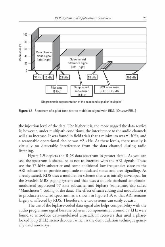
the injection level of the data. The higher it is, the more rugged the data serviceis; however, under multipath conditions, the interference to the audio channelswill also increase. It was found in field trials that a minimum was ±1 kHz, anda reasonable operational choice was ±2 kHz. At these levels, there usually isvirtually no detectable interference from the data channel during radiolistening.
Figure 1.9 depicts the RDS data spectrum in greater detail. As you cansee, the spectrum is shaped so as not to interfere with the ARI signals. Theseuse the 57 kHz subcarrier and some additional low frequencies close to theARI subcarrier to provide amplitude-modulated status and area signalling. Asalready stated, RDS uses a modulation scheme that was initially developed forthe Swedish MBS paging system and that uses a double sideband amplitude-modulated suppressed 57 kHz subcarrier and biphase (sometimes also called“Manchester”) coding of the data. The effect of such coding and modulation isto produce a notched spectrum, as is shown in Figure 1.9, so that ARI remainslargely unaffected by RDS. Therefore, the two systems can easily coexist.
The use of the biphase-coded data signal also helps compatibility with theaudio programme signal because coherent components at around 57 kHz werefound to introduce data-modulated crosstalk in receivers that used a phase-locked loop (PLL) stereo decoder, which is the demodulation technique gener-ally used nowadays.
RDS System and Applications Overview 29
Diagrammatic representation of the baseband signal or "multiplex"
Pilot tone19 kHz
Main channelmono signal(left right)+
100
Sub-channeldifference signal
(left right)−
30 Hz 15 kHz 23 kHz 53 kHz
Suppressedsub-carrier
38 kHz
RDS sub-carrier57 kHz 2.5 kHz±
100 kHz
Mod
ulat
ion
(%) 80
60
40
20
0
Figure 1.8 Spectrum of a pilot-tone stereo multiplex signal with RDS. (Source: EBU.)
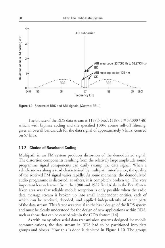
The bit rate of the RDS data stream is 1187.5 bits/s (1187.5 = 57,000 / 48)which, with biphase coding and the specified 100% cosine roll-off filtering,gives an overall bandwidth for the data signal of approximately 5 kHz, centredon 57 kHz.
1.7.2 Choice of Baseband Coding
Multipath in an FM system produces distortion of the demodulated signal.The distortion components resulting from the relatively large amplitude soundprogramme signal components can easily swamp the data signal. When avehicle moves along a road characterised by multipath interference, the qualityof the received FM signal varies rapidly. At some moments, the demodulatedaudio programme is distorted; at others, it is completely broken up. The veryimportant lesson learned from the 1980 and 1982 field trials in the Bern/Inter-laken area was that reliable mobile reception is only possible when the radiodata message stream is broken up into small independent entities, each ofwhich can be received, decoded, and applied independently of other partsof the data stream. This factor was crucial to the basic design of the RDS systemand must be clearly understood for the design of new applications within RDS,such as those that can be carried within the ODA feature [14].
As with many other serial data transmission systems designed for mobilecommunications, the data stream in RDS had to be partitioned into datagroups and blocks. How this is done is depicted in Figure 1.10. The groups
30 RDS: The Radio Data System
ARI subcarrier
ARI area code (23.7500 Hz to 53.9773 Hz)BK
ARI message code (125 Hz)SK
RDS RDS
Frequency kHz54.6 55 56 57 58 59 59.3
4
3
2
1
0
Devi
atio
nof
mai
nFM
carr
ier,
kHz
Figure 1.9 Spectra of RDS and ARI signals. (Source: EBU.)
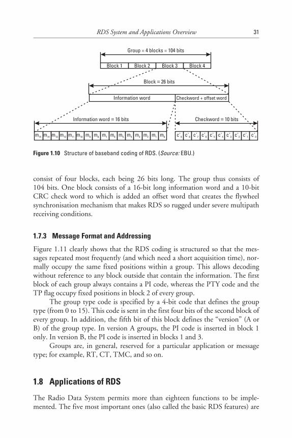
consist of four blocks, each being 26 bits long. The group thus consists of104 bits. One block consists of a 16-bit long information word and a 10-bitCRC check word to which is added an offset word that creates the flywheelsynchronisation mechanism that makes RDS so rugged under severe multipathreceiving conditions.
1.7.3 Message Format and Addressing
Figure 1.11 clearly shows that the RDS coding is structured so that the mes-sages repeated most frequently (and which need a short acquisition time), nor-mally occupy the same fixed positions within a group. This allows decodingwithout reference to any block outside that contain the information. The firstblock of each group always contains a PI code, whereas the PTY code and theTP flag occupy fixed positions in block 2 of every group.
The group type code is specified by a 4-bit code that defines the grouptype (from 0 to 15). This code is sent in the first four bits of the second block ofevery group. In addition, the fifth bit of this block defines the “version” (A orB) of the group type. In version A groups, the PI code is inserted in block 1only. In version B, the PI code is inserted in blocks 1 and 3.
Groups are, in general, reserved for a particular application or messagetype; for example, RT, CT, TMC, and so on.
1.8 Applications of RDS
The Radio Data System permits more than eighteen functions to be imple-mented. The five most important ones (also called the basic RDS features) are
RDS System and Applications Overview 31
Block 1 Block 2 Block 3 Block 4
Group = 4 blocks = 104 bits
m15 m14 m13 m12 m11 m10 m9 m8 m7 m6 m5 m4 m3 m2 m1 m0
Information word 16 bits=
c'9 c'8 c'7 c'6 c'5 c'4 c'3 c'2 c'1 c'0
Checkword 10 bits=
Block 26 bits=
Checkword + offset wordInformation word
Figure 1.10 Structure of baseband coding of RDS. (Source: EBU.)

32RDS:The
RadioData
System
Checkword+
offset A
Checkword
offset B+
Checkwordoffset
C or C'+
Checkword
offset D+PI code
Grouptypecode
B0 TP
PTYPI
t1
First transmitted bit of group Last transmitted bit of group
Block 1 Block 2 Block 3 Block 4
t2
One group 104 bits 87.6 ms= ≈
Offset C version AOffset C' version B
==
Most significant bit Leastsignificant bit
A3 A2 A1 A0 B0
Trafficprog.code
PT4 PT3 PT2 PT1 PT0
4-bit group type code 0 version A1 version B
==
Figure 1.11 Message format and addressing. (Source: EBU.)
implemented everywhere and are intended primarily to be used in the mobilereception mode with car radios having automated tuning functions:
• Programme Identification (PI): A 16-bit code containing a countrysymbol, a regional code, and a number permitting the identification ofthe broadcaster and the particular programme.
• Programme Service (PS) name: Comprising eight alphanumeric charac-ters from an uppercase and lowercase character set defined by theEBU, and serving to give the listener information about the name ofthe programme.
• Alternative Frequency (AF) lists: One or more lists can be transmitted,each containing a maximum of 25 frequencies (represented by the cor-responding band II channel numbers) of transmitters or rebroadcasttransmitters relaying the same programme.
If the programme will contain announcements about local and/orregional traffic situations, the following features should be used to identify this:
• Traffic Programme (TP) code: Serving to identify programmes that,from time to time, carry messages addressed to motorists.
• Traffic Announcement (TA) signal: Switches a traffic announcement toa preset volume level and, if the motorist is listening to a cassette ratherthan the radio, stops the cassette and switches the radio on to receivethe traffic message instead.
Most of the following other features are optional:
• Decoder Information (DI): Indicates one of a number of operatingmodes for the receiver (e.g., mono, stereo).
• Music Speech (MS): A flag indicating whether music or speech is beingbroadcasted. May be used by the receiver to give independent volumesettings of music or speech.
• Programme TYpe (PTY): An identification code to be transmitted witheach programme item and which is intended to specify the currentProgramme Type within 31 possibilities. This code could be used forsearch tuning.
RDS System and Applications Overview 33

• Programme Item Number (PIN): A code identifying a particular pro-gramme (by start time and date) to enable automatic on/off switchingof receivers.
• RadioText (RT): Either 32 or 64 characters of text for display byreceivers.
• Enhanced Other Networks information (EON): RDS information relat-ing to other broadcast services. The information includes the PI andAF for quick retuning to the service referenced, TP, TA, PTY, andPIN of these services.
• Transparent Data Channel (TDC): Provides for a continuous datastream to receivers and associated peripherals (e.g., printer or homecomputer).
• In-House (IH): A data channel for use only by the broadcaster.
• Clock Time and date (CT): A code, usually originated from standardtime transmissions, to enable receivers to display the current time anddate. This is also used to synchronise various receivers.
• Radio Paging (RP) and enhanced Radio Paging: Offers the possibility ofmobile pocket pagers with alphanumeric display of messages and alert-ing bleeps.
• Emergency Warning System (EWS): A feature using a very small amountof data for emergency warning services such as national disasters andhazardous chemical spills.
An additional and quite universal feature most recently being devel-oped is:
• Open Data Application (ODA): which permits new applications to bedesigned and implemented in still available data groups with an appli-cation identification registration from the EBU or NAB. Interestingexamples are differential GPS such as the Rasant system and the con-trol of variable message signs.
1.9 Data Capacity Impact on Applications
Attention is drawn to the fact that the RDS data transmission capacity is ratherlimited. The system can accommodate only 11.4 data groups per second; thatis, only 673 usable information bits per second. This takes into account
34 RDS: The Radio Data System
that each information word contains 16 bits per block and that the data grouphas five address bits that are used for the group type identification.
Under no circumstances can one implement all possible RDS featureswithin the same data channel. For a better understanding of these constraints,see Appendix E.
1.10 System Performance and Reliability
Here, we briefly summarise what we consider in greater detail in Appendix C.Field tests carried out by a number of broadcasters’ research laboratories allcame to the same conclusions.
When signals of the ARI system are broadcast simultaneously with RDS,most first-generation RDS demodulators show some significant degradation ofthe data transmission reliability, which is due to interference from the ARI sig-nals under multipath receiving conditions. This may be overcome however, byfiltering out the ARI signal by means of a notch filter at the RDS demodulatorinput and an appropriate RDS signal injection level of at least ±2 kHz.
One of the methods used to investigate the reliability of the RDS channelfor the transmission of real applications such as PI and PS, which are veryimportant for the operation of the automated tuning function of an RDSreceiver, is to measure the “waiting time” between successful acquisitions of aparticular RDS message.
Relatively low RDS data injection levels, say ±1 kHz, offer a reliable datasystem only under receiving conditions with little or no multipath effects (typi-cally towns with flat buildings and flat countryside). In a moving receiver, oncemultipath effects occur due to reflections of the transmitted signal caused byhigh-rise buildings or mountains, there is a sharp decrease in the reliability fora correct reception of the applications. It all depends on whether the data isrepeated sufficiently often in the data stream. In ODA applications, additionalCRC check words may also be considered to better protect the data transmis-sion application that is implemented.
Studies usually confirm the ruggedness of the fixed format PI codes com-pared, for example, with the variable addressed format of the PS codes. There-fore, consumer receivers often store the PS name, displaying the stored nameonce the PI code is received. Therefore, the use of the PS name to convey, forexample, some limited dynamic text information composed of scrolling text orshort words of a maximum of eight characters to the radio listener, is just notadmissible.
In cases where Radio Paging is implemented within the RDS data stream,the small antenna used in these special paging receivers and the reliability of
RDS System and Applications Overview 35
reception required (which is often within buildings) make an RDS injectionlevel of at least ±4 kHz necessary.
Repetition of message elements transmitted within RDS is also a generalrequirement. This applies to, for example, RP and TMC messages, but to alesser degree to RT where the occasional reception of a wrong character will beperceived as less annoying to the reader.
Error detection has to be applied to all messages, and error correction canonly be applied to some applications; for example, RT—that is, when an errorcaused by the correction system is not perceived as being critical.
References
[1] Ilmonen, K., Listener preferences for Loudness balance of broadcasts with special consid-erations to listening in noise, Yleisradio (Finnish Broadcasting Corporation), ResearchReport no. 12/1971.
[2] van der Heide, H. J., “Possibilities for the introduction and application of a programmecode in sound broadcasting,” Berichte der 4, NTG-Hörrundfunktagung, Düsseldorf,Germany, Nov. 1976.
[3] Sundin, L., and A. Sanfridsson, Programme Identification in FM broadcasting, SwedishTelecommunications Administration, Report RI 4022/77, 1977.
[4] MacEwan, D., “Radio in the 80’s Broadcasting and the ideal sound receiver of the future,”Wireless World, May 1977, pp. 36–40.
[5] Ely, S. R., VHF Radio Data: Experimental BBC transmissions, BBC Research Depart-ment Report No. BBC RD, 1981-1984.
[6] Ely, S. R., “The impact of radio-data on broadcast receivers,” The Radio and ElectronicEngineer, Vol. 52, No. 5, 1982, pp. 291–296.
[7] Swedish Telecommunication Administration: Paging receiver for the Radio Data System,Doc. 1301/A694 3798 (Alternative B), 1986.
[8] CCIR: Report 900-1 Radio-paging systems-standardisation of code and format(Annex II), 1986.
[9] ITU-R Recommendation B.S.643-2 (1995), System for automatic tuning and other appli-cations in FM radio receivers for use with the pilot-tone system.
[10] Mielke, J., and K. H. Schwaiger, “Progress with the RDS system and experimentalresults,” EBU Review, No. 217, June 1986.
[11] Shute, S. A., “The EBU Radio Data System,” International Broadcast Engineer, May/June1987.
[12] Kopitz, D., “Radio Data System-from specification to practical reality,” EBU TechnicalReview, No. 233, Feb. 1989.
36 RDS: The Radio Data System
[13] Parnall, S. J., and J. L. Riley, “RDS developments,” International Broadcasting ConventionDigest, 1990, pp. 234–240.
[14] Ely, S. R., and D. Jeffrey, Traffic Information Broadcasting in Mobile Information Systems,J. Walker, Ed., Norwood, MA: Artech House, 1990, Chapter 5.
[15] Borras Amoedo, J. M., El RDS: Una Radio Intelligente, Biblioteca Tecnica PIONEER,Ediciones Tecnicas Rede, S. A., 1991.
[16] Universal Encoder Communications Protocol UECP-EBU doc. SPB 490, version 5.1,European Broadcasting Union, 17A Ancienne Route, CH-1218 Geneva, Aug. 1997.
[17] EBU: Proposed enhancements of the EBU on CENELEC EN 50067 (RDS), Doc.SPB 482, European Broadcasting Union, 17A Ancienne Route, CH-1218 Geneva,Switzerland, 1990.
[18] EBU SPB 485: Rev 1992-Allocation of country/area identification codes in RDS, nowincluded in CENELEC EN 50067:1998.
[19] EN 50067:1990-Specifications of the Radio Data System RDS, European Committee forElectrical Standardisation (CENELEC), 35B rue de Stassart, B-1050 Brussels.
[20] EN 50067:1992-Specifications of the Radio Data System RDS, European Committee forElectrical Standardisation (CENELEC), 35B rue de Stassart, B-1050 Brussels.
[21] Marks, B., “The development of RDS standards,” 3rd Montreux International RadioSymposium: Engineering Symposium Record, 1996, pp. 133–142.
[22] CENELEC EN 50067:1998 - Specifications of the Radio Data System (RDS.) forVHF/FM broadcasting, European Committee for Electrical Standardisation (CENELEC),35B rue de Stassart, B-1050 Brussels, Switzerland, April 1998.
[23] EIA/NAB, National Radio Systems Committee: United States RBDS Standard-Specification of the Radio Broadcast Data System (RBDS), Jan. 8, 1993.
[24] EIA/NAB, National Radio Systems Committee: United States RBDS Standard version2.0, Specification of the Radio Broadcast Data System (RBDS), 1998.
[25] EBU Guidelines for the implementation of the RDS system, Doc. Tech 3260, EuropeanBroadcasting Union, 17A Ancienne Route, CH-1218 Geneva, Switzerland, Jan. 1990.
[26] NAB RDS Applications-Opportunities for Radio Broadcasters, NAB Science and Tech-nology Department, 1771 N Street, N.W., Washington D C , 1995.
[27] EBU, Specifications of the radio data system RDS for VHF/FM sound broadcasting,Doc. Tech 3244 and Supplements 1 to 4. European Broadcasting Union, 17A AncienneRoute, CH-1218 Geneva, Switzerland, 1984.
RDS System and Applications Overview 37
2Differences Between RDS and RBDS
2.1 Introduction
In this chapter, the small but subtle differences are explained between theEuropean RDS CENELEC standard and the North American RBDS NationalAssociation of Broadcasters/Electronic Industry Association (NAB/EIA) speci-fication (a voluntary U.S. industry standard). Through close collaborationbetween the RDS Forum and the U.S. National Radio Systems Committee,both standards were harmonised to a high degree in order to facilitate themanufacturing of receivers for both markets. Since receivers can detect auto-matically where they are operated, they can, in principle, configure themselvesautomatically. Therefore, it is important that encoder/receiver designers anddata service providers clearly understand the subtle differences between RDSand RBDS.
2.2 The RDS Component Within RBDS
The RDS for FM broadcasting in the frequency range 87.5–108.0 MHz wasdeveloped within the European Broadcasting Union (EBU), as explained inChapter 1. This system was specified by the EBU in 1984, and has now beenintroduced in the large majority of European countries as well as a number ofother countries all over the world. It is also now being used by a significant por-tion of the FM broadcast stations in the United States. Later, the system wasenhanced through several modifications as more experience was gained duringdifferent implementations—in 1987, on large broadcast networks that were
39
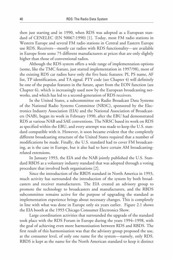
then just starting and in 1990, when RDS was adopted as a European stan-dard of CENELEC (EN 50067:1990) [1]. Today, most FM radio stations inWestern Europe and several FM radio stations in Central and Eastern Europeuse RDS. Receivers—mostly car radios with RDS functionality—are availablein Europe from some 75 different manufacturers at prices that are only slightlyhigher than those of conventional radios.
Although the RDS system offers a wide range of implementation options(some, like the TMC feature, just started implementation in 1997/98), most ofthe existing RDS car radios have only the five basic features: PI, PS name, AFlist, TP identification, and TA signal. PTY code (see Chapter 4) will definitelybe one of the popular features in the future, apart from the EON function (seeChapter 6), which is increasingly used now by the European broadcasting net-works, and which has led to a second-generation of RDS receivers.
In the United States, a subcommittee on Radio Broadcast Data Systemsof the National Radio Systems Committee (NRSC), sponsored by the Elec-tronics Industry Association (EIA) and the National Association of Broadcast-ers (NAB), began its work in February 1990, after the EBU had demonstratedRDS at various NAB and SAE conventions. The NRSC based its work on RDSas specified within the EBU, and every attempt was made to keep the U.S. stan-dard compatible with it. However, it soon became evident that the completelydifferent broadcasting structure of the United States required that a number ofmodifications be made. Finally, the U.S. standard had to cover FM broadcast-ing, as is the case in Europe, but it also had to have certain AM broadcasting-related extensions.
In January 1993, the EIA and the NAB jointly published the U.S. Stan-dard RBDS as a voluntary industry standard that was adopted through a votingprocedure that involved both organisations [2].
Since the introduction of the RBDS standard in North America in 1993,much activity has surrounded the introduction of the system by both broad-casters and receiver manufacturers. The EIA created an advisory group topromote the technology to broadcasters and manufacturers, and the RBDSsubcommittee remains active for the purpose of upgrading the standard asimplementation experience brings about necessary changes. This is completelyin line with what was done in Europe only six years earlier. Figure 2.1 showsthe EIA booth at the 1993 Chicago Consumer Electronics Show.
Large coordination activities that surrounded the upgrade of the standardtook place with the RDS Forum in Europe during the years 1994–1998, withthe goal of achieving even more harmonisation between RDS and RBDS. Thefirst result of this harmonisation was that the advisory group proposed the use,at the consumer level, of only one name for the system—namely, only RDS.RBDS is kept as the name for the North American standard to keep it distinct
40 RDS: The Radio Data System

from the European RDS CENELEC standard, since there is no single worldstandard combining the elements of both standards.
Recent changes to both standards, which were officially adopted in early1998, have resulted in a significant harmonisation of features, allowing thedevelopment of global broadcast equipment, consumer receivers, and data serv-ices. The newly revised RDS and RBDS standards both move forward into anew era for FM data services. All changes have been devised to be fully back-ward compatible with the prior standards while offering a tremendous amountfor future growth and extension. The new ODA feature (see Chapter 9) willeven permit the definition of additional functionality without the need to revisethe RDS/RBDS standards yet again.
Figure 2.2 depicts the actual construction of the RBDS standard. As isshown in this functional diagram of the RBDS standard, the RDS standardis entirely contained within the RBDS standard, and this is true word by word;that is, the corresponding text is identical with the copyright being agreed toby all the organisations concerned. In the RBDS standard, the few remainingfunctional differences are added within the appropriate sections of the text orwithin entirely new annexes. This reflects the fact that the functional core ofRBDS is completely identical with RDS. This can also be seen by examiningthe RDS/RBDS group allocations shown in Table 2.1 [3,4].
Differences Between RDS and RBDS 41
Figure 2.1 RBDS promotion during the 1993 Chicago Consumer Electronics Show. From leftto right: Casey (Denon), Haber (Radio World), Lebow (Sage Alert Systems), andKopitz. (Source: EBU.)
42 RDS: The Radio Data System
NRSCRBDS
standard
1998
CENELECRDS
standardEN50067
1998
Placeholderfor
AM RDS
Section 6
Specificationfor in-receiver
databasesystem
Section 7 andAnnex R
PI codesfor
NorthAmerica
Annex D
PTY codesfor
NorthAmerica
Annex F
Specificationfor MMBS
radio paging
Annex P
Emergencyalert
system
Annex Q
= + + + + + +
Figure 2.2 Functional diagram of the RBDS standard. (Source: NAB/EIA.)
Table 2.1RDS/RBDS Data Groups
Group Type Description of Usage
0A Basic tuning and switching information only
0B Basic tuning and switching information only
1A Programme Item Number and slow labelling codes
1B Programme Item Number
2A RadioText only
2B RadioText only
3A Applications IDentification for ODA only
3B Open Data Applications—ODA
4A Clock Time and date only
4B Open Data Application—sODA
5A Transparent Data Channels (32 channels) or ODA
5B Transparent Data Channels (32 channels) or ODA
6A In-House applications or ODA
6B In-House applications or ODA
7A Radio Paging or ODA
7B Open Data Application—sODA
8A Traffic Message Channel or ODA
8B Open Data Application—sODA
9A Emergency Warning System or ODA
9B Open Data Application—sODA
10A Programme TYpe Name
10B Open Data Application—sODA
11A Open Data Application—sODA
11B Open Data Application—sODA
12A Open Data Application—sODA
12B Open Data Application—sODA
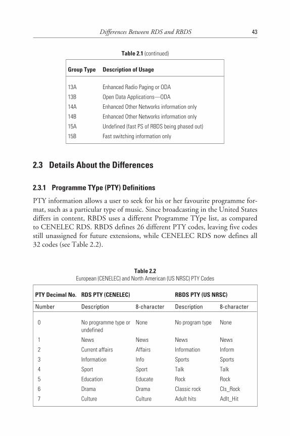
2.3 Details About the Differences
2.3.1 Programme TYpe (PTY) Definitions
PTY information allows a user to seek for his or her favourite programme for-mat, such as a particular type of music. Since broadcasting in the United Statesdiffers in content, RBDS uses a different Programme TYpe list, as comparedto CENELEC RDS. RBDS defines 26 different PTY codes, leaving five codesstill unassigned for future extensions, while CENELEC RDS now defines all32 codes (see Table 2.2).
Differences Between RDS and RBDS 43
Table 2.1 (continued)
Group Type Description of Usage
13A Enhanced Radio Paging or ODA
13B Open Data Applications—ODA
14A Enhanced Other Networks information only
14B Enhanced Other Networks information only
15A Undefined (fast PS of RBDS being phased out)
15B Fast switching information only
Table 2.2European (CENELEC) and North American (US NRSC) PTY Codes
PTY Decimal No. RDS PTY (CENELEC) RBDS PTY (US NRSC)
Number Description 8-character Description 8-character
0 No programme type orundefined
None No program type None
1 News News News News
2 Current affairs Affairs Information Inform
3 Information Info Sports Sports
4 Sport Sport Talk Talk
5 Education Educate Rock Rock
6 Drama Drama Classic rock Cls_Rock
7 Culture Culture Adult hits Adlt_Hit
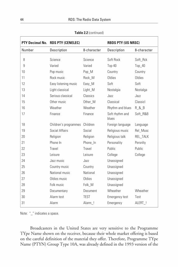
Broadcasters in the United States are very sensitive to the ProgrammeTYpe Name shown on the receiver, because their whole market offering is basedon the careful definition of the material they offer. Therefore, Programme TYpeName (PTYN) Group Type 10A, was already defined in the 1993 version of the
44 RDS: The Radio Data System
Table 2.2 (continued)
PTY Decimal No. RDS PTY (CENELEC) RBDS PTY (US NRSC)
Number Description 8-character Description 8-character
8 Science Science Soft Rock Soft_Rck
9 Varied Varied Top 40 Top_40
10 Pop music Pop_M Country Country
11 Rock music Rock_M Oldies Oldies
12 Easy listening music Easy_M Soft Soft
13 Light classical Light_M Nostalgia Nostalga
14 Serious classical Classics Jazz Jazz
15 Other music Other_M Classical Classicl
16 Weather Weather Rhythm and blues R_&_B
17 Finance Finance Soft rhythm andblues
Soft_R&B
18 Children’s programmes Children Foreign language Language
19 Social Affairs Social Religious music Rel_Musc
20 Religion Religion Religious talk REL_TALK
21 Phone In Phone_In Personality Persnlty
22 Travel Travel Public Public
23 Leisure Leisure College College
24 Jazz music Jazz Unassigned
25 Country music Country Unassigned
26 National music National Unassigned
27 Oldies music Oldies Unassigned
28 Folk music Folk_M Unassigned
29 Documentary Document Wheather Wheather
30 Alarm test TEST Emergency test Test
31 Alarm Alarm_! Emergency ALERT_!
Note: “_” indicates a space.
RBDS standard, but it is now included in both the new RDS and RBDSstandards. The default PTY eight-character name should be shown during thescanning process. Once the receiver stops on a station with the default PTYcategory, a more specific PTY category may be given with PTYN; for example,“SPORTS” is coded by PTY and then the sport is detailed as “BASEBALL” byPTYN. The PTYN is not intended to change the default eight characters thatwill be used during the search, but only to more clearly define the ProgrammeTYpe once tuned to a programme. However, if the broadcaster is satisfied withthe default PTY name, he or she will not need to use data transmission capacityto add PTYN detail to the default name.
Receivers that implement the PTY feature should allow the user to selectone entry from the two different PTY tables (European CENELEC version andNorth American RBDS version). The table may also be automatically switchedusing the Extended Country Code (ECC).
2.3.2 Programme Identification (PI) Coding
In North America (United States, Canada and Mexico), PI codes are based oncall letters rather than being assigned by a regulatory organisation—as carriedout throughout the rest of the world. A portion of the PI codes are reserved fornetwork usage and also for assignment to stations in Canada and Mexico.During the upgrade to the RBDS standard, several mistakes were discovered inthe noncall-based PI codes, which had to be corrected. For further details, seeAppendix F.
The ECC table was modified for these changes as well. The new PIassignments allow 3,584 possible nonregional PI codes for Canada and Mexico,as well as 765 national network PI codes for all three countries: the UnitedStates, Canada, and Mexico.
The ECC codes allow receivers to identify the country that the broadcastis coming from. Since PI Country Identifier codes are limited in number (i.e.,there are only 15 codes available), they must be repeated throughout the world.When the PI country identifier code is received in conjunction with the ECC,the exact country of origin can be identified. The updated ECC code table hasbeen expanded to be international in scope, and reflects recent changes in thepolitical landscape. It is contained in Annexes D and N of the RDS and RBDSstandards (for details about these codes, see Appendix G in this book). TheECC should be transmitted by all broadcasters, and it is recommended that itbe a default automatic transmission in encoders.
The ECC supports the development of global receivers that can auto-matically compensate for things such as the following:
Differences Between RDS and RBDS 45
1. E blocks (MMBS);
2. PI codes;
3. PTY tables;
4. Tuning range and step;
5. FM de-emphasis (North America uses a 75 µs pre-emphasis in thetransmitted AF response, while Europe uses 50 µs).
2.3.3 Programme Service (PS) Name
During the update to the CENELEC RDS standard, a movement was madein the RDS Forum to specifically prohibit stations from dynamically changingthe PS name [5]. In some countries, broadcasters have used the PS display as atext-messaging feature similar to RT, but only eight characters at a time.
The design intent of PS is to provide a label for the receiver preset that isinvariant, since receivers incorporating the AF will switch from one frequencyto another in following the selected programme. To combat unintendeddynamic use of the PS, the RDS standard adopted strict wording on the use ofthe PS feature.
During adoption of the RBDS draft, considerable debate about“dynamic” PS resulted in less stringent requirements for PS usage. Set makersshould realise this difference—although in actual practical system design theyshould not prepare for dynamic PS, but just cope with occasional changes of PSas required by the broadcaster to signal a different broadcast network configu-ration caused by linking or regionalisation.
Excerpts from the text of both standards follows:
• RDS standard: The Programme Service name comprises eight charac-ters, intended for static display on a receiver. It is the primary aid to lis-teners in programme service identification and selection. The use of PSto transmit text other than a single eight-character name is not permit-ted. Transmission of a PS name usually takes four type 0A groups, butto allow an instant display of the PS when a receiver pre-set is selected,the PS name is often stored for subsequent recall from memory whena programme service is selected. For this reason, PS should generallybe invariant. If a broadcaster wishes to transmit longer ProgrammeService names, programme-related information or any other text, thenRT provides this feature.
A similar effect could be experienced with a dynamic text transmission ofPTYN. As a result, dynamic PS and PTYN transmissions are expressly forbidden.
46 RDS: The Radio Data System
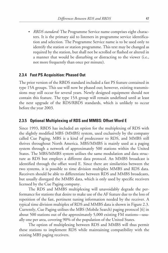
• RBDS standard: The Programme Service name comprises eight charac-ters. It is the primary aid to listeners in programme service identifica-tion and selection. The Programme Service name is to be used only toidentify the station or station programme. This text may be changed asrequired by the station, but shall not be scrolled or flashed or altered ina manner that would be disturbing or distracting to the viewer (i.e.,not more frequently than once per minute).
2.3.4 Fast PS Acquisition: Phased Out
The prior version of the RBDS standard included a fast PS feature contained intype 15A groups. This use will now be phased out; however, existing transmis-sions may still occur for several years. Newly designed equipment should notcontain this feature. The type 15A group will remain undefined until at leastthe next upgrade of the RDS/RBDS standards, which is unlikely to occurbefore the year 2003.
2.3.5 Optional Multiplexing of RDS and MMBS: Offset Word E
Since 1993, RBDS has included an option for the multiplexing of RDS withthe slightly modified MBS (MMBS) system, used exclusively by the companycalled Cue Paging. MBS is a kind of predecessor to RDS, and MMBS stillthrives throughout North America. MBS/MMBS is mainly used as a pagingsystem through a network of approximately 500 stations within the UnitedStates. The MBS/MMBS system utilises the same modulation and data struc-ture as RDS but employs a different data protocol. An MMBS broadcast isidentified through the offset word E. Since there are similarities between thetwo systems, it is possible to time division multiplex MMBS and RDS data.Receivers should be able to differentiate between RDS and MMBS broadcasts,but usually disregard the MMBS data, which is only used by specific receiverslicensed by the Cue Paging company.
The RDS and MMBS multiplexing will unavoidably degrade the per-formance for stations that desire to make use of the AF feature due to the loss ofrepetition of the fast, pertinent tuning information needed by the receiver. Atypical time division multiplex of RDS and MMBS data is shown in Figure 2.3.Currently, Cue Paging utilises the MBS (Mobile Search) paging protocol [6] inabout 500 stations out of the approximately 5,000 existing FM stations—usu-ally one per area, covering 90% of the population of the United States.
The option of multiplexing between RDS and MMBS will thus permitthese stations to implement RDS while maintaining compatibility with theexisting MBS paging receivers.
Differences Between RDS and RBDS 47
48RDS:The
RadioData
System
Checkwordoffset E 0
+=
ReceiverID
Message
Message
MMBS0A 0A 0A0A
MMBSMMBS
Block 1 Block 2 Block 3
1 s (11.4 groups)
System codeand
sleep code
Checkwordoffset E 0
+=
Checkwordoffset E 0
+=
Block 8
16 bits
16 bits
10 bits
10 bits
Checkwordoffset E 0
+=
16 bits 16 bits10 bits 10 bits
Figure 2.3 RDS/MMBS multiplexing. (Source: EBU.)

2.3.6 Optional ID Logic Feature
The ID Logic feature is a licensed technology (PRS Corporation) that allowsthe incorporation of an in-receiver database that contains the programme for-mat type and call letters for all AM and FM stations. When combined withRDS, ID Logic can provide similar data and features for non-RDS FM and allAM stations. The I-RDS feature allows the database to be updated through anRDS open data application (ODA) so that station information can be updatedand maintained automatically. The specification of ID Logic is containedwithin a separate section of the RBDS standard, while the I-RDS ODA isdescribed in detail within an annex.
According to our knowledge, the ID-Logic feature was not used anywherein 1997, which is probably due to the difficulty of creating the necessary agree-ments for a reliable and future-proof broadcast infrastructure to be operatedusing this technology.
2.3.7 Optional ODA Emergency Alert System
Within the RBDS standard, the emergency alert system ODA protocol isdefined for use in the United States. This optional feature set is constructedaround the Federal Communication Commission’s (FCC) newly developedEAS system and is open for public use. RDS and RBDS allow the silent trans-mission of emergency information. This has been combined with existingconsumer-oriented emergency features to allow additional feature functionalityto consumer receivers, as well. The EAS ODA can well accommodate privateemergency systems, but it should also be noted that Annex Q of the new RBDSstandard has no corresponding section in the RDS standard.
In Europe, there is not yet much interest in this kind of application, andit is thought that it has little or no relevance for consumer receivers. The imple-mentation will most likely remain restricted to special alert radios to be usedunder specific well-defined conditions applying to closed user groups only.
2.3.8 Option for Adding an AM Radio Data System
Section 5 of the new RBDS standard serves as a “placeholder” for a future AMdata system (AMDS). The development of an AM data system is still supportedby the NRSC and has been studied for more than five years by the RBDS sub-committee without an agreement being found as to the modulation system tobe used. The requirement, difficult to meet, is that any such system must becompatible with the C-Quam AM stereo system.
Differences Between RDS and RBDS 49
In Europe, tests in the 1980s showed that low rate data could be carriedby low frequency (LF) and medium frequency (MF) transmissions. For manyyears, the BBC 198 kHz transmitter has used phase modulation of the carrier toachieve 50 bps, but tests on “Hochschule für Verkehrswesen Dresden” showedthat it was possible to add a data stream of 200 bps using a phase modulation of±15 degrees to an AM transmitter, with minimal degradation of received audioquality.
Since 1986, extensive field trials have been conducted to find an appro-priate baseband coding to match the bit error conditions of AM channels in LF,MF, and high frequency (HF).
AMDS [7], as it has become known, owes its origin to these trials. During1994, the EBU ad hoc group R1/AMDS prepared a comprehensive proposalfor the standardisation of the baseband coding for AMDS, leaving the modula-tion system still undecided since the phase modulation that was used inthe tests is incompatible with the C-Quam AM stereo system still used in theUnited States.
2.3.9 Location/Navigation Information Deleted
The 1993 version of the RBDS standard had defined type 3A groups for loca-tion/navigation information. However, since this specification left a large numberof options open, in which studies were continued within the RBDS subcommittee,nobody had implemented this feature, which was of no interest in Europe.
The new RBDS standard deleted that kind of specification and redefinedthe type 3A group to the Open Data Application’s IDentification (AID) asrequired in the new RDS standard. As a result, the type 3A group is completelyidentical in both RDS and RBDS.
2.4 Use of the RDS Logos
In the United States, the RDS logos (shown in Figure 2.4) are now a registeredtrademark of the National Association of Broadcasters (NAB). The reason forthis registration is solely to protect the logos against other registrations by indi-viduals seeking to exploit them for commercial advantage. The copyright of thelogos is jointly owned by the BBC and the EBU. Initially, these logos weredeveloped by the BBC, and in August 1988, they were first published by theEBU in their RDS newsletters.
Before the logo can be used in the United States on any product, manu-facturers will need to perform a self-certification test on their equipment,and submit a self-certification application to the Consumer Electronic
50 RDS: The Radio Data System
Manufacturers Association (CEMA). The cost is $100.00 per year, permanufacturer. Only equipment displaying the logo will require registration.Figure 2.5 illustrates an RDS product demonstration.
Note that consumer receivers must use the term “RDS” rather than“RBDS.” The use of the RBDS term is only permitted when referring to theNorth American standard.
In Europe, there is no self-certification test required, and the RDS logoscan be used freely on equipment that implements any of the RDS features.
2.5 Conclusions
RDS and RBDS both allow broadcasters and receiver manufacturers to decidewhich of the possible standardised features they wish to implement. It is in thatcontext that the question arises as to whether RDS manufacturers can adapttheir software to modify existing products that were designed for Europe to cre-ate products for sale in the United States.
The answer to this question is not very obvious because of the largerange of implementation options that are theoretically permitted in the twostandards. However, in reality, the problem is not too difficult to be solved sim-ply because most existing RDS car radios have implemented only the five basicfeatures already mentioned above, and these also appear to be quite sufficientduring the initial phase of the RBDS implementation in the United States.
Differences Between RDS and RBDS 51
Figure 2.4 The RDS logos. (Source: EBU.)
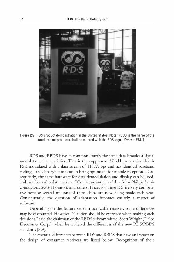
RDS and RBDS have in common exactly the same data broadcast signalmodulation characteristics. This is the suppressed 57 kHz subcarrier that isPSK modulated with a data stream of 1187.5 bps and has identical basebandcoding—the data synchronisation being optimised for mobile reception. Con-sequently, the same hardware for data demodulation and display can be used,and suitable radio data decoder ICs are currently available from Philips Semi-conductors, SGS-Thomson, and others. Prices for these ICs are very competi-tive because several millions of these chips are now being made each year.Consequently, the question of adaptation becomes entirely a matter ofsoftware.
Depending on the feature set of a particular receiver, some differencesmay be discounted. However, “Caution should be exercised when making suchdecisions,” said the chairman of the RBDS subcommittee, Scott Wright (DelcoElectronics Corp.), when he analysed the differences of the new RDS/RBDSstandards [8,9].
The essential differences between RDS and RBDS that have an impact onthe design of consumer receivers are listed below. Recognition of these
52 RDS: The Radio Data System
Figure 2.5 RDS product demonstration in the United States. Note: RBDS is the name of thestandard, but products shall be marked with the RDS logo. (Source: EBU.)
differences is essential to all manufacturers interested in a global market forRDS equipment and consumer receivers. The main differences are as follows:
• Programme TYpe definitions (PTY): The RBDS standard calls out a dif-ferent set of programme type terms.
• Programme Identification coding (PI): North American PI codes differin functionality: This affects alternate frequency switching andregionalisation.
• Dynamic Programme Service (PS) name: The RBDS standard differs inits allowance of “nondistracting” changes to the PS.
• Phase out of fast Programme Service (PS) feature: Type 15A group ofRBDS was previously defined for use as a fast PS feature. This usage isbeing discontinued.
• Multiplexed MMBS: This is used as a commercial nationwide pagingsystem in the United States. Since it shares the same modulation for-mat and data protocol as RDS, it may be time division multiplexedwith RDS. MMBS uses the offset word E (see also Appendix B), whichis defined in both the RDS and RBDS standards to permit this multi-plexing to take place without disturbing synchronisation of thereceived RDS/RBDS data stream.
If a receiver designer aimed at adapting existing RDS receiver designs foruse in North America and made a receiver comply with the RBDS standard, allthe above, as we have seen, indicates that the software changes that are neededare relatively small. Recognition of the offset word E (all zeros) would definitelybe the most important change to be made, and when PTY is implemented inthe receiver, the RBDS code table has to be used, of course. Finally, the PIcodes have to be interpreted differently as far as AF switching and regionalisa-tion are concerned (see Appendix F). That is practically all that is neededto make RDS receivers work correctly in North America (i.e., United States,Canada and Mexico).
References
[1] CENELEC, Specifications of the radio data system; EN 50067:1992, European Commit-tee for Electrotechnical Standardisation, Brussels, Belgium, 1992.
Differences Between RDS and RBDS 53
[2] EIA/NAB National Radio Systems Committee, United States RBDS Standard, Specifica-tion of the Radio Broadcast Data System (RBDS), Washington, D.C., Jan. 8, 1993.
[3] CENELEC, Specification of the radio data system (RDS) for VHF/FM sound broadcast-ing, EN50067:1998, European Committee for Electrotechnical Standardisation, Brussels,Belgium.
[4] EIA/NAB National Radio Systems Committee RBDS Subcommittee-United StatesRBDS Standard, Draft 2.0, Specification of the Radio Broadcast Data System (RBDS),Washington, D.C., Aug. 1997.
[5] RDS Forum, Document 96/007: Comments on Programme Service name (PS)-Non-standard transmission of type 0 group. European Broadcasting Union/RDS Forum, 17A,Ancienne Route, CH-1218 Geneva, Switzerland, 1996.
[6] Swedish Telecommunication Administration (Televerket)-Paging Receiver for theSwedish Public Radio Paging System, 76-1650-ZE, 1976.
[7] EBU, Proposal for a Data System for AM transmitters, EBU Document GT R1/AMDS009, GT R1 910, European Broadcasting Union, 17A, Ancienne Route, CH-1218,Geneva, Switzerland, Sept. 9, 1994.
[8] Wright, S., The Broadcaster’s Guide to RDS, Focal Press, 1997.
[9] EIA/NAB, Wright, S., “RBDS versus RDS: What are the differences and how can receiv-ers cope with both systems?” 1997.
[10] Beale, T., D. Kopitz, “RDS in Europe, RBDS in the USA - What are the differences andhow can receivers cope with both systems?” EBU Technical Review, No. 255, 1993.
54 RDS: The Radio Data System
3RDS Features Serving as Tuning Aids
3.1 Introduction
In this chapter, RDS features that help the tuning functionality of FM receiversare introduced. In this connotation, a feature in RDS is considered to be some-thing that gives a distinctive functionality. Originally in the earliest versions ofthe specification, these tended to be defined into a single RDS group such asRadioText, which is described in Chapter 4 (although there are notable excep-tions such as PI, which is described in this chapter). But, as the specificationwas enhanced, some features were defined that make use of more than onegroup to be transmitted (e.g. Radio Paging, which is described in Chapter 8) toobtain full functionality.
Many of these features are considered to be included in the minimum setof RDS features that would be implemented initially by a transmissionoperator.
3.2 Basic RDS Features
The RDS specification, EN 50067:1998, defines a number of RDS grouptypes that are generally reserved for a particular application. The type 0Agroup—basic tuning and switching information—is a special case, designedto carry the fundamental components of RDS all together in a single groupthat will be transmitted frequently to convey many pieces of information to anRDS receiver to enable it to perform a considerable number of tuning func-tions. These fundamental components, known as features, allow a degree of
55

automatic tuning in an RDS receiver and allow it to present tuning-relatedinformation to the user. The type 0A group contains all of the following RDSfeatures: Alternative Frequency (AF), Decoder Information (DI), MusicSpeech (MS), PI, Programme Type (PTY), Traffic Announcement (TA), andTraffic programme (TP). The type 0B group contains the same features exceptthe AF feature [1].
The implementation of the type 0 groups in any RDS transmission isessential, and not optional—unlike many of the other possible groups inRDS—because it carries vital information required for automated tuning of anRDS receiver.
From these basic RDS features serving as tuning aids, it is useful to ini-tially consider AF, PI, PS, and TP. They can be seen in various locations withinthe type 0A group, as shown in Figure 3.1. Furthermore, PI and TP can befound in all other groups to provide immediate information to an RDS receiverfrom every single group decoded.
The type 0B group has a very similar structure, but there is a simple dif-ference in block 3, as shown in Figure 3.2. In block 3, the AF feature is notused, so it is replaced by a second PI code. This group is normally used bysingle-service RDS transmissions, where there is no need for an AF list becausethere are, indeed, no alternates.
3.3 Programme Identification—PI
The PI code is transmitted in block 1 of every single RDS group. PI is amachine-readable code that is not intended for direct display. It is uniquelyallocated to each individual programme service within a geographical areato enable it to be distinguished from all other programme services. (Formore detail about PI coding, see Appendix F.) Irrespective of frequenciesused, transmissions with identical PI codes in any given area must have theidentical audio programme. A receiver may therefore freely switch betweentwo different transmissions with the same PI code in order to track opti-mum reception, assured that programme audio will be identical on bothtransmitters.
One important application of the information contained in the PI code isto enable an RDS receiver to automatically search for an alternative frequencyin case of bad reception of the programme to which the receiver is tuned; thecriteria for the changeover to the new frequency would be the presence of a bet-ter signal having the same PI code.
The PI code consists of 16 bits and is usually referred to by four hexadeci-mal characters, or nibbles, as shown in Figure 3.3.
56 RDS: The Radio Data System
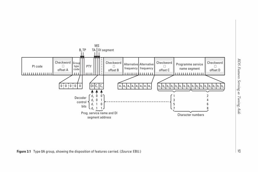
RD
SFeaturesServing
asTuning
Aids
57
Checkword
offset A+PI code PTY
Alternativefrequency
Programme servicename segment
TAB0 TP DI segment
0 0 000
Prog. service name and DIsegment address
Alternativefrequency
Grouptypecode
C0C1DI
MS
1357
2468
Character numbers
0011
0101
d3
d2
d1
d0
Decodercontrol
bits
Checkword
offset B+
Checkword
offset C+
Checkword
offset D+
a7 a6 a5 a4 a3 a2 a1 a0 b7 b6 b5 b4 b3 b2 b1 b0 b7 b6 b5 b4 b3 b2 b1 b0
Figure 3.1 Type 0A group, showing the disposition of features carried. (Source: EBU.)
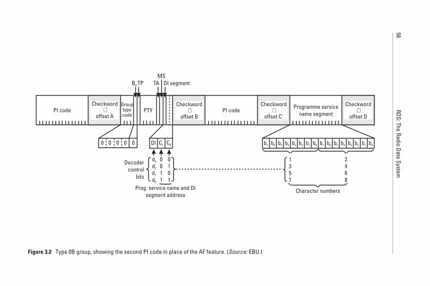
58RDS:The
RadioData
System
Checkword
offset A+PI code PI codePTY Programme service
name segment
TAB0 TP DI segment
0 0 000
Prog. service name and DIsegment address
Grouptypecode
C0C1DI
MS
1357
2468
Character numbers
0011
0101
d3
d2
d1
d0
Decodercontrol
bits
Checkword
offset B+
Checkword
offset C'+
Checkword
offset D+
b7 b6 b5 b4 b3 b2 b1 b0 b7 b6 b5 b4 b3 b2 b1 b0
Figure 3.2 Type 0B group, showing the second PI code in place of the AF feature. (Source: EBU.)
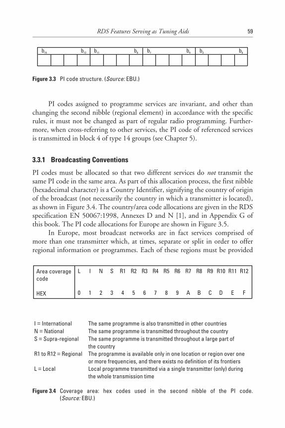
PI codes assigned to programme services are invariant, and other thanchanging the second nibble (regional element) in accordance with the specificrules, it must not be changed as part of regular radio programming. Further-more, when cross-referring to other services, the PI code of referenced servicesis transmitted in block 4 of type 14 groups (see Chapter 5).
3.3.1 Broadcasting Conventions
PI codes must be allocated so that two different services do not transmit thesame PI code in the same area. As part of this allocation process, the first nibble(hexadecimal character) is a Country Identifier, signifying the country of originof the broadcast (not necessarily the country in which a transmitter is located),as shown in Figure 3.4. The country/area code allocations are given in the RDSspecification EN 50067:1998, Annexes D and N [1], and in Appendix G ofthis book. The PI code allocations for Europe are shown in Figure 3.5.
In Europe, most broadcast networks are in fact services comprised ofmore than one transmitter which, at times, separate or split in order to offerregional information or programmes. Each of these regions must be provided
RDS Features Serving as Tuning Aids 59
b15 b12 b11 b8 b7 b4 b3 b0
Figure 3.3 PI code structure. (Source: EBU.)
Area coveragecode
HEX
L I N S R1 R2 R3 R4 R5 R6 R7 R8 R9 R10 R11 R12
0 1 2 3 4 5 6 7 8 9 A B C D E F
I InternationalN NationalS Supra-regional
R1 to R12 Regional
L Local
===
=
=
The same programme is also transmitted in other countriesThe same programme is transmitted throughout the countryThe same programme is transmitted throughout a large part ofthe countryThe programme is available only in one location or region over oneor more frequencies, and there exists no definition of its frontiersLocal programme transmitted via a single transmitter (only) duringthe whole transmission time
==
=
=
=
Figure 3.4 Coverage area: hex codes used in the second nibble of the PI code.(Source: EBU.)
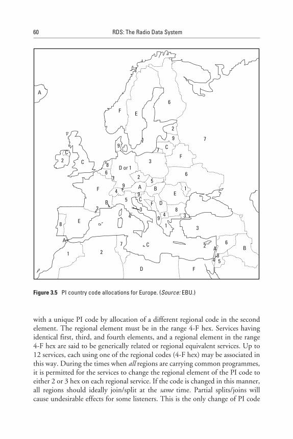
with a unique PI code by allocation of a different regional code in the secondelement. The regional element must be in the range 4-F hex. Services havingidentical first, third, and fourth elements, and a regional element in the range4-F hex are said to be generically related or regional equivalent services. Up to12 services, each using one of the regional codes (4-F hex) may be associated inthis way. During the times when all regions are carrying common programmes,it is permitted for the services to change the regional element of the PI code toeither 2 or 3 hex on each regional service. If the code is changed in this manner,all regions should ideally join/split at the same time. Partial splits/joins willcause undesirable effects for some listeners. This is the only change of PI code
60 RDS: The Radio Data System
2 C
F
68 D or 1
7
9
3
25
4A B
59C
F D
E
6
43
94
8
1
3
3
9
E8
A
1 27
D
C 2 A6
B
54
F
8
A
F E
6
F7 C
9
2
7
3
C
B
1
Figure 3.5 PI country code allocations for Europe. (Source: EBU.)
normally permitted. Changing PI codes is not permitted on programme serv-ices used as part of an Enhanced Other Network (EON).
Although within a country code area, PI codes may be reused at geo-graphically separated areas, it is preferable that each service be allocated aunique code. RDS receivers use the PI code as addresses against which to storeprogramme attributes (Programme Service name, list of alternative frequencies,etc.). Use of the same PI code by more than one programme service wouldprobably cause data about one service to be misassociated with another havingthe same PI code.
To prevent having to reuse PI codes and yet still be able to associatetogether more than 12 regional equivalent services, the Extended Generic (EG)feature should be used. The word generic has a somewhat special meaning inRDS and involves some very complex ideas, which require a very full apprecia-tion of how broadcasters view their services. Furthermore, sometimes theytransmit common programmes in a network and this must be signalled to anRDS receiver. A more detailed explanation can be found in the EBU/RDSForum document BPN 009: RDS Guidelines [2].
In this case, PI codes that have the extended generic indicator (EG) flagset, and are identical in the first and third elements only, and regional elementsin the range 4-F hex, are also regional equivalent services to each other. Up to192 (12 × 16) such services may be grouped in this way.
3.3.2 Reception
The PI code is arguably the single most important feature of RDS. It uniquelyidentifies a programme service, within any geographical area, where broadcastssharing the same PI code are guaranteed to be carrying identical programmeaudio. Although there are many designs possible for an RDS receiver, evalua-tion of the PI code is fundamental to operation.
In any receiver with preset memories, it is essential for the PI code of thebroadcast to be stored in nonvolatile memory when a service is assigned to amemory location. If no signal with the correct PI code is available, on the lasttuned frequency or AFs, when a preset is chosen, the receiver should scan theFM band, stopping on each receivable RDS service and evaluating the PI code.
The correct transmission to select is that which gives the best signal with aPI code matching that recalled from memory. If no service with a matching PIcode can be found, a receiver should select a transmission with (in order of pri-ority) a PI code identical in the first, third, and fourth elements or a PI codeidentical in the first and third elements only. Although accepting these trans-missions as regional variations of the wanted service, under no circumstances
RDS Features Serving as Tuning Aids 61

should the PI code stored in preset memory be overwritten by any otherPI code.
An RDS receiver must always evaluate the PI code and confirm it is cor-rect before it remains tuned to a different transmission. Usually, switchingbetween two different transmissions should occur only when PI codes are iden-tical in all four nibbles. Optionally, a receiver may provide a mode that enablesreceivers to switch automatically to other regional variants of the same service.
3.4 Programme Service (PS) Name
The PS name is an eight-character alphanumeric label transmitted by thebroadcaster to identify to the listener the name of the tuned service. It is notintended for automatic tuning purposes. The PS name is transmitted two char-acters at a time in either the type 0A or type 0B groups. (See Figures 3.1 and3.2 above.) A complete PS name requires a minimum of four groups, which atthe recommended rate takes just one second to be transmitted. As the receptionof a PS name takes a minimum of one second, and even longer in adversereception conditions, receivers may store the PS name to allow instant recallupon the user accessing a preset memory. Since broadcasters may choose totransmit PS names in either type 0A or 0B groups, receivers must be capable ofusing both transmission methods.
PS names can also be carried as part of the EON data and then providethe PS name of the cross-referenced programme services.
The PS name should only be used as a static feature, but it may occasion-ally change. For example, regional services may carry their own PS name duringthe day when they originate their own programmes. However, the PS name ischanged when they are transmitting a common programme originated by oneof these broadcast services during the evenings and nights.
Due to these design parameters for PS, the use of the PS feature to trans-mit text other than a single eight-character representation of the ProgrammeService name is not permitted. If a broadcaster wishes to transmit moreprogramme service information, programme-related information, or any othertext, then the RadioText feature provides the capability to achieve dynamic textpossibilities. The RDS Forum has been instrumental in keeping media regula-tors informed about the correct use of PS, which has, unfortunately, beenincorrectly implemented by several broadcasters who have not realised theimportance of these design parameters for PS [3].
Appropriate use of spaces, punctuation, and combinations of upper-case/lowercase characters and accented characters should all be used to improve
62 RDS: The Radio Data System
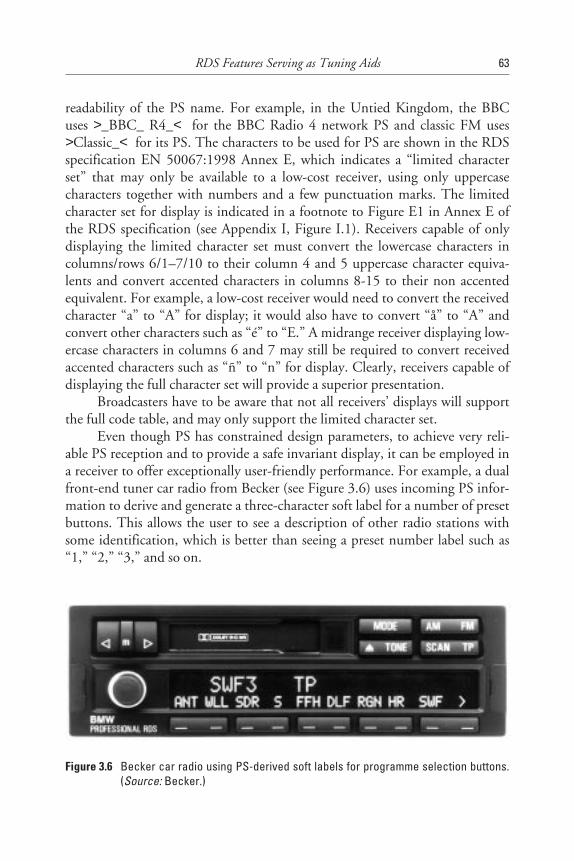
readability of the PS name. For example, in the Untied Kingdom, the BBCuses >_BBC_ R4_< for the BBC Radio 4 network PS and classic FM uses>Classic_< for its PS. The characters to be used for PS are shown in the RDSspecification EN 50067:1998 Annex E, which indicates a “limited characterset” that may only be available to a low-cost receiver, using only uppercasecharacters together with numbers and a few punctuation marks. The limitedcharacter set for display is indicated in a footnote to Figure E1 in Annex E ofthe RDS specification (see Appendix I, Figure I.1). Receivers capable of onlydisplaying the limited character set must convert the lowercase characters incolumns/rows 6/1–7/10 to their column 4 and 5 uppercase character equiva-lents and convert accented characters in columns 8-15 to their non accentedequivalent. For example, a low-cost receiver would need to convert the receivedcharacter “a” to “A” for display; it would also have to convert “å” to “A” andconvert other characters such as “é” to “E.” A midrange receiver displaying low-ercase characters in columns 6 and 7 may still be required to convert receivedaccented characters such as “ñ” to “n” for display. Clearly, receivers capable ofdisplaying the full character set will provide a superior presentation.
Broadcasters have to be aware that not all receivers’ displays will supportthe full code table, and may only support the limited character set.
Even though PS has constrained design parameters, to achieve very reli-able PS reception and to provide a safe invariant display, it can be employed ina receiver to offer exceptionally user-friendly performance. For example, a dualfront-end tuner car radio from Becker (see Figure 3.6) uses incoming PS infor-mation to derive and generate a three-character soft label for a number of presetbuttons. This allows the user to see a description of other radio stations withsome identification, which is better than seeing a preset number label such as“1,” “2,” “3,” and so on.
RDS Features Serving as Tuning Aids 63
Figure 3.6 Becker car radio using PS-derived soft labels for programme selection buttons.(Source: Becker.)
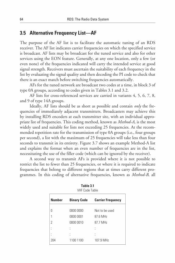
3.5 Alternative Frequency List—AF
The purpose of the AF list is to facilitate the automatic tuning of an RDSreceiver. The AF list indicates carrier frequencies on which the specified serviceis broadcast. AF lists may be broadcast for the tuned service and also for otherservices using the EON feature. Generally, at any one location, only a few (oreven none) of the frequencies indicated will carry the intended service at goodsignal strength. Receivers must ascertain the suitability of each frequency in thelist by evaluating the signal quality and then decoding the PI code to check thatthere is an exact match before switching frequencies automatically.
AFs for the tuned network are broadcast two codes at a time, in block 3 oftype 0A groups, according to codes given in Tables 3.1 and 3.2.
AF lists for cross-referenced services are carried in variants 4, 5, 6, 7, 8,and 9 of type 14A groups.
Ideally, AF lists should be as short as possible and contain only the fre-quencies of immediately adjacent transmitters. Broadcasters may achieve thisby installing RDS encoders at each transmitter site, with an individual appro-priate list of frequencies. This coding method, known as Method-A, is the mostwidely used and suitable for lists not exceeding 25 frequencies. At the recom-mended repetition rate for the transmission of type 0A groups (i.e., four groupsper second), a list with the maximum of 25 frequencies will take less than fourseconds to transmit in its entirety. Figure 3.7 shows an example Method-A listand explains the format when an even number of frequencies are in the list,necessitating the use of the filler code (which can be ignored by the receiver).
A second way to transmit AFs is provided where it is not possible torestrict the list to fewer than 25 frequencies, or where it is required to indicatefrequencies that belong to different regions that at times carry different pro-grammes. In this coding of alternative frequencies, known as Method-B, all
64 RDS: The Radio Data System
Table 3.1VHF Code Table
Number Binary Code Carrier Frequency
0 0000 0000 Not to be used
1 0000 0001 87.6 MHz
2 0000 0010 87.7 MHz
: : :: : :204 1100 1100 107.9 MHz
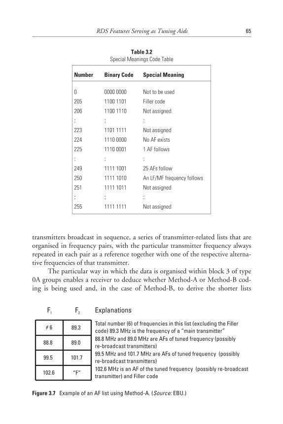
transmitters broadcast in sequence, a series of transmitter-related lists that areorganised in frequency pairs, with the particular transmitter frequency alwaysrepeated in each pair as a reference together with one of the respective alterna-tive frequencies of that transmitter.
The particular way in which the data is organised within block 3 of type0A groups enables a receiver to deduce whether Method-A or Method-B cod-ing is being used and, in the case of Method-B, to derive the shorter lists
RDS Features Serving as Tuning Aids 65
Table 3.2Special Meanings Code Table
Number Binary Code Special Meaning
0 0000 0000 Not to be used
205 1100 1101 Filler code
206 1100 1110 Not assigned
: : :223 1101 1111 Not assigned
224 1110 0000 No AF exists
225 1110 0001 1 AF follows
: : :249 1111 1001 25 AFs follow
250 1111 1010 An LF/MF frequency follows
251 1111 1011 Not assigned
: : :255 1111 1111 Not assigned
F1 F2 Explanations
# 6 89.3Total number (6) of frequencies in this list (excluding the Fillercode) 89.3 MHz is the frequency of a “main transmitter”
88.8 89.088.8 MHz and 89.0 MHz are AFs of tuned frequency (possiblyre-broadcast transmitters)
99.5 101.799.5 MHz and 101.7 MHz are AFs of tuned frequency (possiblyre-broadcast transmitters)
102.6 “F”102.6 MHz is an AF of the tuned frequency (possibly re-broadcasttransmitter) and Filler code
Figure 3.7 Example of an AF list using Method-A. (Source: EBU.)
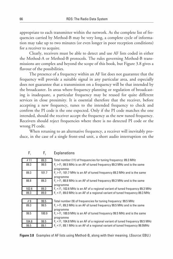
appropriate to each transmitter within the network. As the complete list of fre-quencies carried by Method-B may be very long, a complete cycle of informa-tion may take up to two minutes (or even longer in poor reception conditions)for a receiver to acquire.
Clearly, receivers must be able to detect and use AF lists coded in eitherthe Method-A or Method-B protocols. The rules governing Method-B trans-missions are complex and beyond the scope of this book, but Figure 3.8 gives aflavour of the possibilities.
The presence of a frequency within an AF list does not guarantee that thefrequency will provide a suitable signal in any particular area, and especiallydoes not guarantee that a transmission on a frequency will be that intended bythe broadcaster. In areas where frequency planning or regulation of broadcast-ing is inadequate, a particular frequency may be reused for quite differentservices in close proximity. It is essential therefore that the receiver, beforeaccepting a new frequency, tunes to the intended frequency to check andconfirm the PI code is the one expected. Only if the PI code matches the oneintended, should the receiver accept the frequency as the new tuned frequency.Receivers should reject frequencies where there is no detected PI code or thewrong PI code.
When retuning to an alternative frequency, a receiver will inevitably pro-duce, in the case of a single front-end unit, a short audio interruption on the
66 RDS: The Radio Data System
F1 F2 Explanations
# 11 89.3 Total number (11) of frequencies for tuning frequency: 89.3 MHz89.3 99.5 F F : 99.5 MHz is an AF of tuned frequency 89.3 MHz and is the same
programme2 1>
89.3 101.7 F F : 101.7 MHz is an AF of tuned frequency 89.3 MHz and is the sameprogramme
2 1>
88.8 89.3 F F : 88.8 MHz is an AF of tuned frequency 89.3 MHz and is the sameprogramme
2 1>
102.6 89.3 F F : 102.6 MHz is an AF of a regional variant of tuned frequency 89.3 MHz2 1<89.3 89.0 F F : 89.0 MHz is an AF of a regional variant of tuned frequency 89.3 MHz2 1<
# 9 99.5 Total number (9) of frequencies for tuning frequency: 99.5 MHz89.3 99.5 F F : 89.3 MHz is an AF of tuned frequency 99.5 MHz and is the same
programme2 1>
99.5 100.9 F F : 100.9 MHz is an AF of tuned frequency 99.5 MHz and is the sameprogramme
2 1>
104.8 99.5 F F : 104.8 MHz is an AF of a regional variant of tuned frequency 99.5 MHz2 1<99.5 89.1 F F : 89.1 MHz is an AF of a regional variant of tuned frequency 99.5MHz2 1<
Figure 3.8 Examples of AF lists using Method-B, along with their meaning. (Source: EBU.)
order of a few milliseconds. Checking a PI code, however, will take at least100 milliseconds, during which time it is possible for a burst of incorrect pro-gramme to be heard, should the particular frequency being tested be other thanthe intended programme. Manufacturers should adopt an intelligent process asa background activity to validate each frequency in the AF list. This will ensurethat a receiver has available for use, when required, a frequency with an opti-mum audio quality and with the correct PI code. Unwanted bursts or break-through from other programmes (of the wrong PI code) and audible mutesshould be avoided. Dual-tuner receivers may have an advantage in AF listevaluation as the checking of PI codes may be done by the second tuner whilethe first tuner continues to provide an uninterrupted audio programme for thelistener.
Some broadcasters may include frequencies of services in their AFlists—simultaneously broadcast on AM perhaps, where there is no suitable FMtransmission. In this case, it is not possible to confirm the frequency that carriesthe intended programme as no PI code is transmitted on normal AM frequen-cies. Use of AM frequencies is probably only viable where the AM tuner part ofthe receiver is separate from the FM one. This would allow a receiver, while theAM tuner is providing an audio programme, to use the FM tuner to performRDS processing and remain active to allow the earliest possible return to an FMtransmission.
3.6 Traffic Programme (TP) Flag
The RDS traffic information service allows listeners to receive traffic reportseven if listening to a CD/cassette, or with the receiver volume turned down ormuted. This service makes use of two flags: the TP and TA flags. The latter isdescribed more fully in Chapter 6; here, the tuning aspect of the TP flag is con-sidered. The TP flag is carried in block 2 of every group type and in block 4 oftype 15B groups. If the TP flag is set to /1/, this indicates that the tuned pro-gramme service provides the RDS traffic service. Broadcasters must not set theTP flag to /1/ unless the TA is also dynamically controlled [1].
Programme services that do not provide traffic services with a switchedTA flag, but instead cross-reference via EON services that do, indicate this bysetting the TP to /0/ and the TA to /1/ on the service. When a listener selectsthe RDS traffic service feature, the receiver uses the status of both the TPand the TA flags to determine whether or not the tuned service can providethe traffic information service itself, or alternatively in the case of an EON-capable receiver, via a cross-referenced service.
RDS Features Serving as Tuning Aids 67
The TP flag can be used by an RDS receiver, since it is in every RDSgroup, to easily evaluate the availability of the RDS traffic service when check-ing a frequency as part of the automatic tuning capability. If the tuned servicedoes not provide the RDS traffic service feature, an RDS receiver should indi-cate this to the listener in some way. Options include the following:
• Visually on the display or audibly by a bleep. This is particularly use-ful when going away from a service and signal strength weakens to thepoint where the TP flag status is becoming uncertain.
• The receiver may automatically start to seek for an alternative serviceable to provide a traffic service.
Alternatively, the receiver could allow the user the option of continuingto listen to the currently tuned service without the traffic service, or manuallyinitiating a search for an alternative service. The options provided might bedifferent, depending on how the user is currently operating the receiver. Forexample, a routine may be as follows:
• If the RDS traffic information service is selected while the user is lis-tening to a CD/cassette, the receiver may automatically seek and tuneto a service capable of providing a traffic service, without either beep-ing or requiring a listener to manually initiate a search.
• If listening to the radio when traffic information is selected, thereceiver should alert the listener visually or with a brief audible warn-ing if the traffic service is unavailable, but not automatically retune.The user then has the option to initiate a seek for another traffic serviceprogramme, if required, or to continue listening to the tuned servicebut without a traffic service.
The same routine should be adopted if, while tuned to a service that wasoffering a traffic information service, the status of the TP/TA flags changes andindicates that a travel service is no longer available. Interference on areas ofpoor reception will mean that the TP and/or the TA flag may at times be readunreliably. It is important that the status of TP and TA flags be evaluated overseveral groups, and that momentary switching be avoided as the result ofshort-term signal fluctuations.
68 RDS: The Radio Data System
A full description of the interaction of TP flags, TA flags, and EON isgiven in Chapter 6.
3.7 Slow Labelling Codes
The RDS specification contains some additional slow labelling codes that areused to support various features. These are specified to be carried in the type 1Agroup at a much slower rate than the main feature groups; for example, onceper minute. The type 1A group also contains the functionality of the PIN fea-ture (see Chapter 5), as shown in Figure 3.9.
3.7.1 Extended Country Code (ECC)
The ECC feature was built into the RDS specification some time after theoriginal publication of the specification, because originally it had been designedonly for Europe and the limited number of country identifier codes (only 15different codes, 1-F hex) could easily be shared across the geographical areaconsidered. Note, for example, in Figure 3.5 that E hex is shared between Swe-den and Spain. The use of RDS has grown considerably since then and, indeed,the need to accommodate newer emerging countries has resulted in the ECCfeature, which is now an important part of the full implementation of severalother features. When widely implemented, this feature allows receivers to ini-tialise automatically for country-specific applications; therefore, broadcastersare being encouraged to implement this feature.
The ECC feature, when read in conjunction with the country code partof a PI code, forms a unique Country Identifier. This may be used by a receiverto automatically select country-specific applications; for example, PTY lan-guage tables, which are different according to the broadcaster’s choice of RDSor RBDS. To support this functionality, the ECC, which consists of 8 bitstransmitted in block 3 of type 1A group’s variant 0 (as shown in Figures 3.9and 3.10), should be transmitted at least once per minute.
Returning to the example of Spain and Sweden, Romania also uses E hexin the allocated country PI code. However, each country is assigned a differentExtended Country Code: Romania = E1, Spain = E2, Sweden = E3, whichtaken together with the country code element of the PI code provides a uniqueCountry Identifier. Full listings of the ECC and PI country/area codes aregiven for European countries in EN 50067:1998 Annex D, and for the rest ofthe world in Annex N (see also Appendix G of this book) [1].
RDS Features Serving as Tuning Aids 69
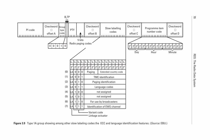
70RDS:The
RadioData
System
20
LA 0
0
0
0
1
1
1
1
0
0
1
1
0
0
1
1
0
1
0
1
0
1
0
1
(0)
(1)
(2)
(3)
(4)
(5)
(6)
(7)
LA
LA
LA
LA
LA
LA
LA
Extended country code
TMC identification
Paging identification
For use by broadcasters
Identification of EWS channel
Variant codeLinkage actuator
Checkword+
offset API code PTY Programme item
number code
B0TP
0 0 010
Grouptypecode
Slow labellingcodes
20
Minute
212223242520212223242021222324
HourDay
Paging
Language codes
not assigned
not assigned
5 bitsRadio paging codes
Checkword+
offset B
Checkword+
offset C
Checkword+
offset D
20 22 21 20 211 210 29 28 27 26 25 24 23 22 21
b1b3 b2b4b6 b5b8 b7b10 b0b9b11b13 b12b14b15
Figure 3.9 Type 1A group showing among other slow labeling codes the ECC and language identification features. (Source: EBU.)
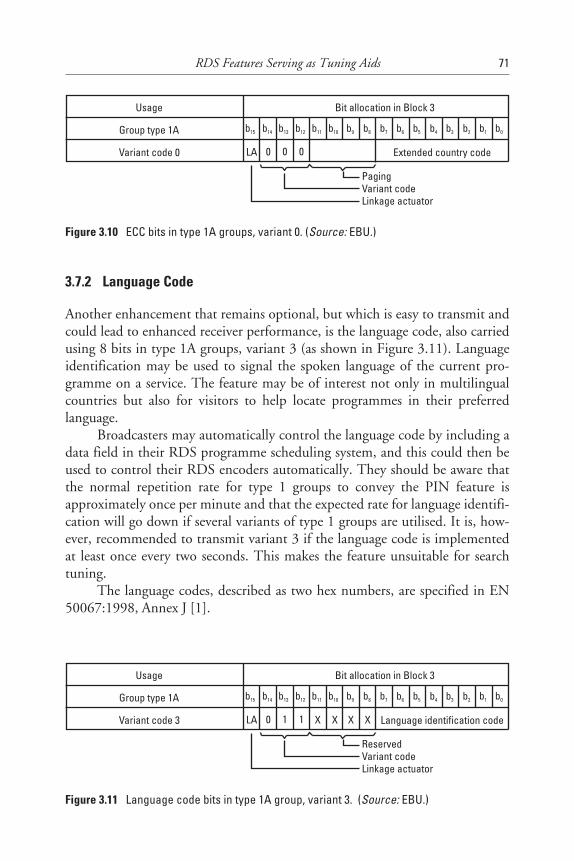
3.7.2 Language Code
Another enhancement that remains optional, but which is easy to transmit andcould lead to enhanced receiver performance, is the language code, also carriedusing 8 bits in type 1A groups, variant 3 (as shown in Figure 3.11). Languageidentification may be used to signal the spoken language of the current pro-gramme on a service. The feature may be of interest not only in multilingualcountries but also for visitors to help locate programmes in their preferredlanguage.
Broadcasters may automatically control the language code by including adata field in their RDS programme scheduling system, and this could then beused to control their RDS encoders automatically. They should be aware thatthe normal repetition rate for type 1 groups to convey the PIN feature isapproximately once per minute and that the expected rate for language identifi-cation will go down if several variants of type 1 groups are utilised. It is, how-ever, recommended to transmit variant 3 if the language code is implementedat least once every two seconds. This makes the feature unsuitable for searchtuning.
The language codes, described as two hex numbers, are specified in EN50067:1998, Annex J [1].
RDS Features Serving as Tuning Aids 71
Usage
Group type 1A
Variant code 0
Bit allocation in Block 3
PagingVariant codeLinkage actuator
LA Extended country code0 0 0
b15 b14 b13 b12 b11 b10 b9 b8 b7 b6 b5 b4 b3 b2 b1 b0
Figure 3.10 ECC bits in type 1A groups, variant 0. (Source: EBU.)
Usage
Group type 1A
Variant code 3
Bit allocation in Block 3
ReservedVariant codeLinkage actuator
LA Language identification code0 1 1 X X X X
b15 b14 b13 b12 b11 b10 b9 b8 b7 b6 b5 b4 b3 b2 b1 b0
Figure 3.11 Language code bits in type 1A group, variant 3. (Source: EBU.)

References
[1] CENELEC, EN 50067:1998-Specifications of the Radio Data System (RDS.) forVHF/FM broadcasting, European Committee for Electrical Standardisation (CENELEC),35B rue de Stassart, B-1050 Brussels, April 1998.
[2] EBU /RDS Forum: BPN 009-Radio Data System (RDS) Guidelines, to be published inAutumn 1998.
[3] RDS Forum Statement, sent with letter DT/969-S/DK dated Feb. 26, 1996, RDS ForumStatement, sent with letter DT/3255-S/DK dated Dec. 9, 1997
72 RDS: The Radio Data System
4Radio Programme-Related RDS Features
4.1 Introduction
This chapter provides a description of the original features and some new fea-tures that are related to the programme content in the audio channel of the FMtransmission.
RDS was originally designed with a strong view that it should provide fea-tures that would let the user benefit from information related to broadcast pro-grammes. In Chapter 3, it was noted that type 0A groups contain both tuningfeatures and programme-related features. One of these programme-related fea-tures, Programme TYpe (PTY), was foreseen by the original developers to besignificant for tuning purposes, so PTY information is conveyed in all RDSgroups. But PTY did not become an early success for RDS; nevertheless, it isbeing implemented by more broadcasters and receiver manufacturers alike nowthat the capabilities offered are better understood—and now that other featuresare also demanding dynamic control over the RDS encoders. More recently,the possibilities of an additional feature, PTYN, has been developed and addedto the RDS specification. [1].
PTY can be used to help the user with the programme selection processand so too can the PIN feature. Other dynamic features to be discussed in thischapter are RadioText—which has many uses, giving both programme-relatedinformation and many other possibilities. Finally, the support features DecoderIdentification/Programme TYpe Identification (DI/PTYI) are described.
73
4.2 Programme TYpe (PTY)
The PTY codes are transmitted, using five bits in block 2 of every single RDSgroup. Additionally, the type 15B group—providing fast basic tuning andswitching information—carries a second opportunity for decoding the PTYcode, which is also transmitted in block 4 (see Figure 4.1). Furthermore, thecode may also be carried in type 14A groups, variant 13 from transmissionscross-referencing a programme service.
The PTY codes are given in the RDS specification EN 50067:1998,Annex F [1]. These codes provide standardised descriptions for broadcasters todepict their programmes according to a short list of 29 standardised choices.Although simple in nature, this feature has been complex for broadcasters toimplement because they do not find it easy to narrow their programme descrip-tions down to a short list. Indeed, it is claimed to be a living issue, with catego-ries gradually changing with broadcasting trends and styles. Table 4.1 showsthe PTY codes, decimal number, the five bits listed, and a very short descrip-tion for each, together with a recommendation for both 8- or 16-character dis-plays in English. The RDS specification has introduced the possibility of16-character displays now that receiver technology is more able to use so manycharacters. Displays in other languages have been developed and agreed uponby experts for many languages through the RDS Forum, and are detailed inAppendix H. In Chapter 2, Table 2.2 shows the RBDS PTY codes list adjacentto the RDS codes list—the differences in the meanings of the same transmittedcodes must be allowed for by RDS receivers being built for the RBDS or RDSmarkets, or by a receiver making use of automated code table switching (whenit can detect the ECC feature, which is described in Chapter 3).
Great care is needed when considering PTY coding in order to conformwith either one specification or the other (e.g., RBDS or RDS). This isbecause the same defining words intended for display, such as Oldies Music,have subtly different meanings according to the specifications and differentcodes used (i.e., RDS uses PTY code 27 for Oldies and RBDS uses PTYcode 11) [1, 2].
As shown in Table 4.2, three of the PTY codes are harmonised in bothRDS and RBDS, since they have special meaning.
Although any PTY code can be used in any mode, some categories aremore suited to one particular mode of operation than another. Programmesthat are generally listened to in their entirety (to receive coherent information)are best matched to receivers offering the PTY-STANDBY mode of operation.This applies to many speech programmes such as news, weather, and drama.
Some broadcasters use PTY to indicate the general nature of their serviceas a whole, with no changes at programme junctions (static PTY); others assess
74 RDS: The Radio Data System
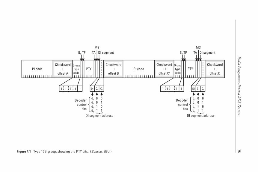
Radio
Programm
e-Related
RD
SFeatures
75
Checkword
offset A+PI code
TA
PTY
B0 TP DI segment
1 1 111
Grouptypecode
MS
PI code PTY
B0 TP DI segment
1 1 111
Grouptypecode
MSTA
DI segment address
C0C1DI
0011
0101
d3
d2
d1
d0
Decodercontrol
bits
DI segment address
C0C1DI
0011
0101
d3
d2
d1
d0
Decodercontrol
bits
Checkword
offset B+
Checkword
offset C'+
Checkword
offset D+
Figure 4.1 Type 15B group, showing the PTY bits. (Source: EBU.)
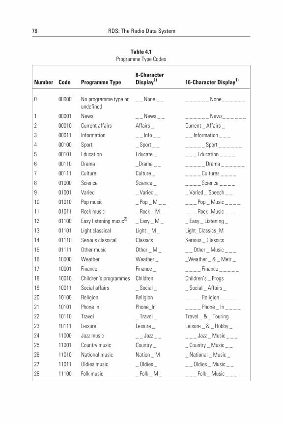
76 RDS: The Radio Data System
Table 4.1Programme Type Codes
Number Code Programme Type8-CharacterDisplay1) 16-Character Display1)
0 00000 No programme type orundefined
_ _ None _ _ _ _ _ _ _ _ None_ _ _ _ _ _
1 00001 News _ _ News _ _ _ _ _ _ _ _ News_ _ _ _ _ _
2 00010 Current affairs Affairs _ Current _ Affairs _
3 00011 Information _ _ Info _ _ _ _ Information _ _ _
4 00100 Sport _ Sport _ _ _ _ _ _ _ Sport _ _ _ _ _ _
5 00101 Education Educate _ _ _ _ Education _ _ _ _
6 00110 Drama _Drama _ _ _ _ _ _ _ Drama _ _ _ _ _ _
7 00111 Culture Culture _ _ _ _ _ Cultures _ _ _ _
8 01000 Science Science _ _ _ _ _ Science _ _ _ _
9 01001 Varied _ Varied _ _ Varied _ Speech _ _
10 01010 Pop music _ Pop _ M _ _ _ _ _ Pop _ Music _ _ _ _
11 01011 Rock music _ Rock _ M _ _ _ _ Rock_Music _ _ _
12 01100 Easy listening music2) _ Easy _ M _ _ Easy _ Listening _
13 01101 Light classical Light _ M _ Light_Classics_M
14 01110 Serious classical Classics Serious _ Classics
15 01111 Other music Other _ M _ _ _ Other _ Music _ _ _
16 10000 Weather Weather _ _Weather _ & _ Metr _
17 10001 Finance Finance _ _ _ _ _ Finance _ _ _ _ _
18 10010 Children’s programmes Children Children’s _ Progs
19 10011 Social affairs _ Social _ _ Social _ Affairs _
20 10100 Religion Religion _ _ _ _ Religion _ _ _ _
21 10101 Phone In Phone_In _ _ _ _ Phone _ In _ _ _ _
22 10110 Travel _ Travel _ Travel _ & _ Touring
23 10111 Leisure Leisure _ Leisure _ & _ Hobby _
24 11000 Jazz music _ _ Jazz _ _ _ _ _ Jazz _ Music _ _ _
25 11001 Country music Country _ _ Country _ Music _ _
26 11010 National music Nation _ M _ National _ Music _
27 11011 Oldies music _ Oldies _ _ _ Oldies _ Music _ _
28 11100 Folk music _ Folk _ M _ _ _ _ Folk _ Music _ _ _

Radio Programme-Related RDS Features 77
Table 4.1 (continued)
Number Code Programme Type8-CharacterDisplay1) 16-Character Display1)
29 11101 Documentary Document _ _ Documentary _ _ _
30 11110 Alarm test _ _ TEST _ _ _ _ _ Alarm _ Test _ _ _
31 11111 Alarm Alarm _ ! _ Alarm _ - _ Alarm _ ! _
1) These short terms are recommended for the 8- or 16-character display of the radio in English. Otherlanguage versions are available from the EBU and the RDS Forum.
2) In earlier versions of the RDS specification, the term MOR music was used for this code, but Easylistening is now more frequently used.
The symbol “_” is used to represent a space in the display
Table 4.2Special PTY Codes and Meanings
Number Programme Type Description
0 No programme type or undefined Indicates a particular programme is undefined
30 Alarm test Indicates a test transmission and may be used bya consumer receiver for display
31 Alarm Indicates a transmission of great importance,carrying information about a national or localemergency and must always be combined with aspoken message
PTY codes 1–29: Allow receivers to offer several modes of operation, which have been more clearlydefined in the last few years.
PTY-SEARCH: Allows a listener to request the receiver to find a particular type of programme, ifavailable.
PTY-SELECT: Allows a listener to request that the receiver indicate which particular ProgrammeTYpes are currently available, and which could be selected.
PTY-STANDBY (or WATCH): Allows a listener to request that the receiver standby or watch out for aparticular Programme TYpe to begin, switching to it when it does.
PTY-STORE: Allows a listener to request that the receiver (incorporating a means of recording audio)store a programme by matching requested PTY code, allowing later listening by the use.
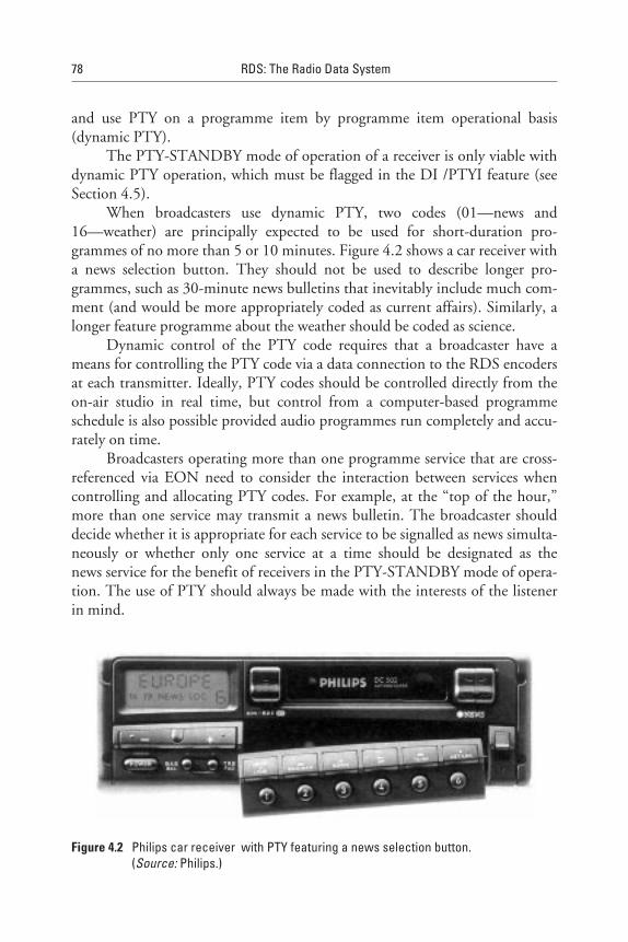
and use PTY on a programme item by programme item operational basis(dynamic PTY).
The PTY-STANDBY mode of operation of a receiver is only viable withdynamic PTY operation, which must be flagged in the DI /PTYI feature (seeSection 4.5).
When broadcasters use dynamic PTY, two codes (01—news and16—weather) are principally expected to be used for short-duration pro-grammes of no more than 5 or 10 minutes. Figure 4.2 shows a car receiver witha news selection button. They should not be used to describe longer pro-grammes, such as 30-minute news bulletins that inevitably include much com-ment (and would be more appropriately coded as current affairs). Similarly, alonger feature programme about the weather should be coded as science.
Dynamic control of the PTY code requires that a broadcaster have ameans for controlling the PTY code via a data connection to the RDS encodersat each transmitter. Ideally, PTY codes should be controlled directly from theon-air studio in real time, but control from a computer-based programmeschedule is also possible provided audio programmes run completely and accu-rately on time.
Broadcasters operating more than one programme service that are cross-referenced via EON need to consider the interaction between services whencontrolling and allocating PTY codes. For example, at the “top of the hour,”more than one service may transmit a news bulletin. The broadcaster shoulddecide whether it is appropriate for each service to be signalled as news simulta-neously or whether only one service at a time should be designated as thenews service for the benefit of receivers in the PTY-STANDBY mode of opera-tion. The use of PTY should always be made with the interests of the listenerin mind.
78 RDS: The Radio Data System
Figure 4.2 Philips car receiver with PTY featuring a news selection button.(Source: Philips.)

4.2.1 PTY-SEARCH Mode
This is the mode most often provided on early RDS receivers, but on itsown (i.e., without PTY-SELECTION or PTY-STANDBY modes, describedbelow), it may have contributed to some customer dissatisfaction. In thePTY-SEARCH mode, a listener requests their desired PTY code by choosingfrom all the types specified and theoretically possible; the receiver then searchesthe band to see if the required PTY code is being broadcast at that time. Whenthe requested code is unavailable, the listener may feel frustrated, and either hasto request another choice or repeat the search until eventually successful.
4.2.2 PTY-SELECTION Mode
In this mode, a receiver presents the listener with a display of all PTY codescurrently available on-air. On a receiver with a large display, all codes may beshown at once so that the listener is able to make an instant selection. On otherreceivers, the PTY codes available could be presented sequentially. The listeneris able to make a selection from those codes actually available.
4.2.3 PTY-STANDBY Mode
This mode (also known as Watch or Wait mode) allows the listener to program areceiver to standby for a particular PTY code to become available. It may only beused reliably when the DI-d3 bit is set to indicate that dynamic PTY is available.When tuned to a non-EON service (or using a non-EON receiver), the only pos-sibility is for a receiver to monitor the PTY code on the “tuned” service and inter-rupt CD/cassette operation when the desired PTY code becomes available.
When tuned to an EON service (and using an EON receiver), thereceiver should also monitor the PTY carried in block 3, variant 1 of type 14Agroups being received, and this will allow the receiver to offer programmesmatching the user’s preselected PTY.
When the required PTY code is no longer available, the receiver mayeither return automatically to the original service or remain tuned to the cur-rent one. If the latter option is chosen, an easy means should be provided toallow a listener to return to the original service (e.g., pressing the PTY button).The same mechanism may be used to allow a listener to return to the originalservice partway through a programme (e.g., after the sports news headlines butbefore the sport in detail).
A receiver in standby mode should not switch across to a service oncethe programme has started (i.e., the receiver should only switch at a PTYtransition).
Radio Programme-Related RDS Features 79
4.2.4 PTY-STORE Mode
This is a further refinement of the PTY-STANDBY mode of operation, whereprogrammes of the requested type are stored in memory or on tape, allowing alistener to replay them when requested. A dual-tuner RDS receiver could storethe news bulletin (PTY code 01) on one service while the user is listening to aprogramme item on another service. The user then has the opportunity to lis-ten to the news at a convenient time. A similar feature is possible with a single-tuner receiver while the listener has chosen to listen to a CD or cassette.
A receiver (dual-tuner) could offer a particularly attractive PTY imple-mentation by combining all these modes of operation into a single routine. Forexample, say a listener requests a sports programme. The receiver searches forPTY code 04 (Sport). It is currently unavailable, so the receiver automaticallygoes into the PTY-STANDBY mode. The receiver then offers the listenerthe selection of categories currently available from which to choose while thereceiver is standing by. The receiver switches across to a sports programme on aservice when it begins. If no sports programme occurs while the user continues tolisten, the receiver remains in the PTY-STANDBY mode and automatically storessports bulletins when they occur, ready for the listener to replay on demand.
4.2.5 PTY-ALARM Function and Testing
PTY code 31, ALARM, indicates a transmission of great importance, carryinginformation concerning a national or local emergency. Therefore, all receiversshould detect this code, sound an alarm, and turn up the volume.
Broadcasters need to occasionally test the broadcast chain to confirm thatit can perform dynamic PTY switching and that they can fully use PTY code30. This code is thought to be particularly useful in testing the system function-ality without causing unnecessary public concern. Consumer receivers shouldneither use this code for searching nor to cause dynamic switching. Receiversmay, if desired, display: >_TEST_< when detecting a PTY code 30 on a pro-gramme service.
4.3 Programme TYpe Name (PTYN)
The PTYN feature has been added to the RDS specification to allow a broad-caster to transmit an eight-character additional description that depicts the pro-gramme content. This can be used to enhance the PTY code description and isexpected to help address the broadcaster’s attitude that the standardised PTYcodes are too limited.
80 RDS: The Radio Data System

It is intended to aid selection of listening more precisely than using thePTY code alone. It cannot be used in PTY-SEARCH, PTY-STANDBY, orPTY-STORE modes of operation (see Section 4.2).
The PTYN feature is transmitted in type 10A groups, four characters at atime; hence, two groups are required to complete the eight-character descrip-tion. The use of PTYN to transmit text other than to a single eight-characterdescription is not permitted, and it must not be used to provide sequentialinformation. Figure 4.3 shows the type 10A group structure, which is designedto convey the eight characters for reconstruction into the normal eight-character display constraint of RDS receivers. The bit format follows that speci-fied for RadioText, but only using eight characters (see Section 4.4).
The PTYN feature is capable of adding more precise descriptions aboutprogramme content than that provided by PTY alone and is particularly usefulto distinguish between different services that use the same general PTY descrip-tion. For example, if there are three services carrying PTY coded as SPORT, thePTYN feature can be used to add the descriptions: >Cricket_<, >_Golf_< and>_Tennis_< to each.
A single-tuner receiver could use PTYN to provide a second-level descrip-tion of the tuned programme service. For example, after a listener makes aprimary selection of SPORT, a receiver tunes to each of the services coded asSPORT in turn and is able to decode and present the PTYN description to thelistener for final selection.
An attractive implementation in a dual-tuner receiver would be to usePTYN to provide a submenu. Such a receiver could present a complete listof both available PTY codes plus PTYNs, if any. For example, if there arethree services broadcasting SPORT, the PTYN feature would provide detailsenabling a listener to chose his or her favourite sport directly from the menu.
4.4 RadioText (RT)
The RT feature is primarily designed for the broadcaster to transmit text mes-sages of up to 64 characters at a time, for display by the fixed-location homereceivers. As shown in Figure 4.4, RadioText uses blocks 3 and 4 in type 2Agroups or block 4 in type 2B groups to transmit text messages of up to 64 and32 characters, respectively. A further four bits in block 2 are used as addressbits, and one bit is used as a Text A/Text B flag which toggles every time a newmessage is transmitted.
The message is transmitted four characters at a time in the type 2A groupsand two characters at a time in the type 2B groups. The text is coded in
Radio Programme-Related RDS Features 81

82RDS:The
RadioData
System
Checkword+
offset API code PTY
Programme typename segment
Programme typename segment
B0 TP
1 0 001 C0
1 2 3 4
5 6 7 8
Text character number Text character number
0
1
b6 b5 b4 b3 b2 b1 b0b7 b6 b5 b4 b3 b2 b1 b0b7 b6 b5 b4 b3 b2 b1 b0b7 b6 b5 b4 b3 b2 b1 b0b7
A/B 000Flag
PTYN segment address
Checkword+
offset B
Checkword+
offset C
Checkword+
offset D
Figure 4.3 Type 10A group, showing the PTYN bits. (Source: EBU.)

Radio
Programm
e-Related
RD
SFeatures
83
C3
Checkword+
offset API code PTY
RadioTextsegment
B0 TP
0 0 001
Grouptypecode
RadioTextsegment
Text segment addressText A/B flag.
A/B C2 C1 C0
15...
61
48...
64
00...1
Text segmentaddress code
Text character number
37...
63
26...
62
00...1
00...1
01...1
b6 b5 b4 b3 b2 b1 b0b7 b6 b5 b4 b3 b2 b1 b0b7 b6 b5 b4 b3 b2 b1 b0b7 b6 b5 b4 b3 b2 b1 b0b7
Checkword+
offset B
Checkword+
offset C
Checkword+
offset D
Figure 4.4 Type 2A groups showing the disposition of the RT feature. (Source: EBU.)
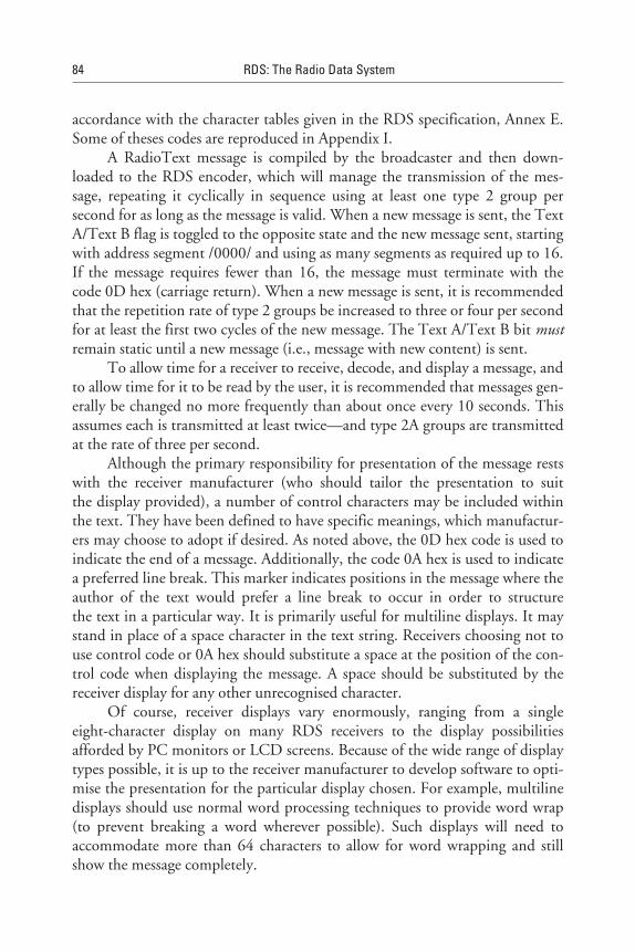
accordance with the character tables given in the RDS specification, Annex E.Some of theses codes are reproduced in Appendix I.
A RadioText message is compiled by the broadcaster and then down-loaded to the RDS encoder, which will manage the transmission of the mes-sage, repeating it cyclically in sequence using at least one type 2 group persecond for as long as the message is valid. When a new message is sent, the TextA/Text B flag is toggled to the opposite state and the new message sent, startingwith address segment /0000/ and using as many segments as required up to 16.If the message requires fewer than 16, the message must terminate with thecode 0D hex (carriage return). When a new message is sent, it is recommendedthat the repetition rate of type 2 groups be increased to three or four per secondfor at least the first two cycles of the new message. The Text A/Text B bit mustremain static until a new message (i.e., message with new content) is sent.
To allow time for a receiver to receive, decode, and display a message, andto allow time for it to be read by the user, it is recommended that messages gen-erally be changed no more frequently than about once every 10 seconds. Thisassumes each is transmitted at least twice—and type 2A groups are transmittedat the rate of three per second.
Although the primary responsibility for presentation of the message restswith the receiver manufacturer (who should tailor the presentation to suitthe display provided), a number of control characters may be included withinthe text. They have been defined to have specific meanings, which manufactur-ers may choose to adopt if desired. As noted above, the 0D hex code is used toindicate the end of a message. Additionally, the code 0A hex is used to indicatea preferred line break. This marker indicates positions in the message where theauthor of the text would prefer a line break to occur in order to structurethe text in a particular way. It is primarily useful for multiline displays. It maystand in place of a space character in the text string. Receivers choosing not touse control code or 0A hex should substitute a space at the position of the con-trol code when displaying the message. A space should be substituted by thereceiver display for any other unrecognised character.
Of course, receiver displays vary enormously, ranging from a singleeight-character display on many RDS receivers to the display possibilitiesafforded by PC monitors or LCD screens. Because of the wide range of displaytypes possible, it is up to the receiver manufacturer to develop software to opti-mise the presentation for the particular display chosen. For example, multilinedisplays should use normal word processing techniques to provide word wrap(to prevent breaking a word wherever possible). Such displays will need toaccommodate more than 64 characters to allow for word wrapping and stillshow the message completely.
84 RDS: The Radio Data System
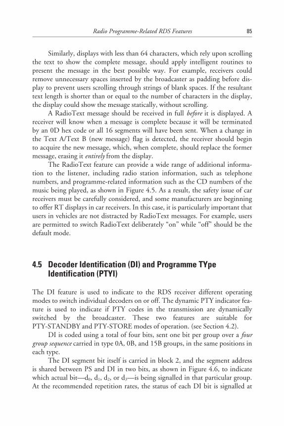
Similarly, displays with less than 64 characters, which rely upon scrollingthe text to show the complete message, should apply intelligent routines topresent the message in the best possible way. For example, receivers couldremove unnecessary spaces inserted by the broadcaster as padding before dis-play to prevent users scrolling through strings of blank spaces. If the resultanttext length is shorter than or equal to the number of characters in the display,the display could show the message statically, without scrolling.
A RadioText message should be received in full before it is displayed. Areceiver will know when a message is complete because it will be terminatedby an 0D hex code or all 16 segments will have been sent. When a change inthe Text A/Text B (new message) flag is detected, the receiver should beginto acquire the new message, which, when complete, should replace the formermessage, erasing it entirely from the display.
The RadioText feature can provide a wide range of additional informa-tion to the listener, including radio station information, such as telephonenumbers, and programme-related information such as the CD numbers of themusic being played, as shown in Figure 4.5. As a result, the safety issue of carreceivers must be carefully considered, and some manufacturers are beginningto offer RT displays in car receivers. In this case, it is particularly important thatusers in vehicles are not distracted by RadioText messages. For example, usersare permitted to switch RadioText deliberately “on” while “off” should be thedefault mode.
4.5 Decoder Identification (DI) and Programme TYpeIdentification (PTYI)
The DI feature is used to indicate to the RDS receiver different operatingmodes to switch individual decoders on or off. The dynamic PTY indicator fea-ture is used to indicate if PTY codes in the transmission are dynamicallyswitched by the broadcaster. These two features are suitable forPTY-STANDBY and PTY-STORE modes of operation. (see Section 4.2).
DI is coded using a total of four bits, sent one bit per group over a fourgroup sequence carried in type 0A, 0B, and 15B groups, in the same positions ineach type.
The DI segment bit itself is carried in block 2, and the segment addressis shared between PS and DI in two bits, as shown in Figure 4.6, to indicatewhich actual bit—d0, d1, d2, or d3—is being signalled in that particular group.At the recommended repetition rates, the status of each DI bit is signalled at
Radio Programme-Related RDS Features 85
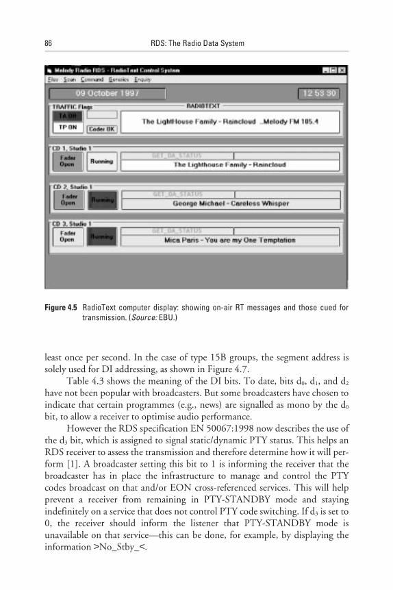
least once per second. In the case of type 15B groups, the segment address issolely used for DI addressing, as shown in Figure 4.7.
Table 4.3 shows the meaning of the DI bits. To date, bits d0, d1, and d2
have not been popular with broadcasters. But some broadcasters have chosen toindicate that certain programmes (e.g., news) are signalled as mono by the d0
bit, to allow a receiver to optimise audio performance.However the RDS specification EN 50067:1998 now describes the use of
the d3 bit, which is assigned to signal static/dynamic PTY status. This helps anRDS receiver to assess the transmission and therefore determine how it will per-form [1]. A broadcaster setting this bit to 1 is informing the receiver that thebroadcaster has in place the infrastructure to manage and control the PTYcodes broadcast on that and/or EON cross-referenced services. This will helpprevent a receiver from remaining in PTY-STANDBY mode and stayingindefinitely on a service that does not control PTY code switching. If d3 is set to0, the receiver should inform the listener that PTY-STANDBY mode isunavailable on that service—this can be done, for example, by displaying theinformation >No_Stby_<.
86 RDS: The Radio Data System
Figure 4.5 RadioText computer display: showing on-air RT messages and those cued fortransmission. (Source: EBU.)

Radio
Programm
e-Related
RD
SFeatures
87
Checkword+
offset API code PI codePTY
Programme servicename segment
TAB0 TP DI segment
0 0 100 b7 b6 b5 b4 b3 b2 b1 b0b7 b6 b5 b4 b3 b2 b1b0
Prog. service name andDI segment address
Grouptypecode
C0C1DI
MS
1357
2468
Character numbers
0011
0101
d3
d2
d1
d0
Decodercontrol
bits
Checkword+
offset B
Checkword+
offset C'
Checkword+
offset D
Figure 4.6 Type 0B groups, showing the DI segment and shared segment address bits. (Source: EBU.)
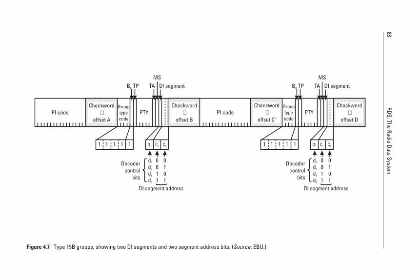
88RDS:The
RadioData
System
Checkword
offset A+PI code
TA
PTY
B0 TP DI segment
1 1 111
Grouptypecode
MS
PI code PTY
B0 TP DI segment
1 1 111
Grouptypecode
MSTA
DI segment address
C0C1DI
0011
0101
d3
d2
d1
d0
Decodercontrol
bits
DI segment address
C0C1DI
0011
0101
d3
d2
d1
d0
Decodercontrol
bits
Checkword
offset B+
Checkword
offset C'+
Checkword
offset D+
Figure 4.7 Type 15B groups, showing two DI segments and two segment address bits. (Source: EBU.)
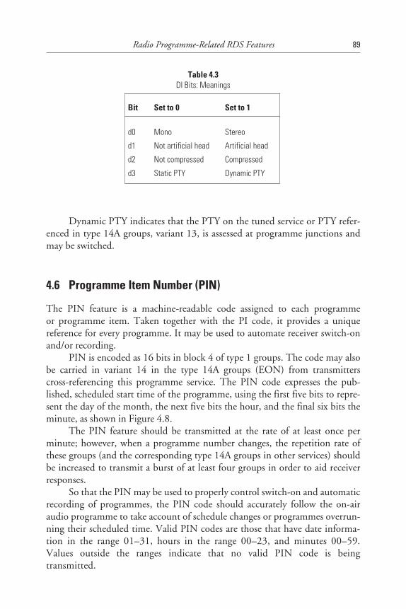
Dynamic PTY indicates that the PTY on the tuned service or PTY refer-enced in type 14A groups, variant 13, is assessed at programme junctions andmay be switched.
4.6 Programme Item Number (PIN)
The PIN feature is a machine-readable code assigned to each programmeor programme item. Taken together with the PI code, it provides a uniquereference for every programme. It may be used to automate receiver switch-onand/or recording.
PIN is encoded as 16 bits in block 4 of type 1 groups. The code may alsobe carried in variant 14 in the type 14A groups (EON) from transmitterscross-referencing this programme service. The PIN code expresses the pub-lished, scheduled start time of the programme, using the first five bits to repre-sent the day of the month, the next five bits the hour, and the final six bits theminute, as shown in Figure 4.8.
The PIN feature should be transmitted at the rate of at least once perminute; however, when a programme number changes, the repetition rate ofthese groups (and the corresponding type 14A groups in other services) shouldbe increased to transmit a burst of at least four groups in order to aid receiverresponses.
So that the PIN may be used to properly control switch-on and automaticrecording of programmes, the PIN code should accurately follow the on-airaudio programme to take account of schedule changes or programmes overrun-ning their scheduled time. Valid PIN codes are those that have date informa-tion in the range 01–31, hours in the range 00–23, and minutes 00–59.Values outside the ranges indicate that no valid PIN code is beingtransmitted.
Radio Programme-Related RDS Features 89
Table 4.3DI Bits: Meanings
Bit Set to 0 Set to 1
d0 Mono Stereo
d1 Not artificial head Artificial head
d2 Not compressed Compressed
d3 Static PTY Dynamic PTY
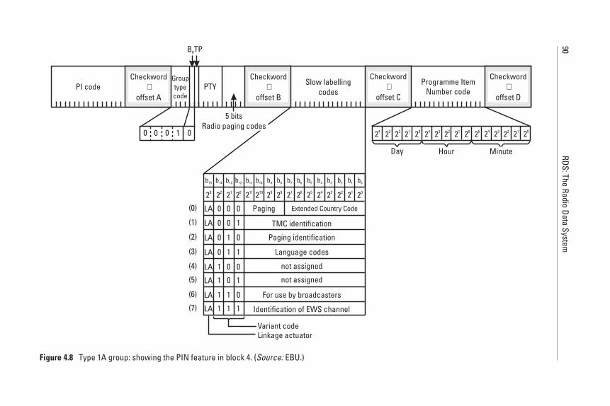
90RDS:The
RadioData
System
20
LA 0
0
0
0
1
1
1
1
0
0
1
1
0
0
1
1
0
1
0
1
0
1
0
1
(0)
(1)
(2)
(3)
(4)
(5)
(6)
(7)
LA
LA
LA
LA
LA
LA
LA
Extended Country Code
TMC identification
Paging identification
For use by broadcasters
Identification of EWS channel
Variant codeLinkage actuator
Checkword+
offset API code PTY Programme Item
Number code
B0TP
0 0 010
Grouptypecode
Slow labellingcodes
20
Minute
212223242520212223242021222324
HourDay
Paging
Language codes
not assigned
not assigned
5 bitsRadio paging codes
Checkword+
offset B
Checkword+
offset C
Checkword+
offset D
20 22 21 20 211 210 29 28 27 26 25 24 23 22 21
b1b3 b2b4b6 b5b8 b7b10 b0b9b11b13 b12b14b15
Figure 4.8 Type 1A group: showing the PIN feature in block 4. (Source: EBU.)
Although implementation of the PIN has generally been very slow tocome to the market, it could be used as a feature that equates to radio ondemand by allowing the listener to enter a PIN into an RDS receiver/cassetteunit that could then record a programme for later recall. The PIN may beimplemented in a receiver in a similar way to the PTY used in thePTY-STANDBY mode. In this case, it would be important that the scheduledstart times published for programmes are presented consistently in all journalsand programme guide listings so that the user can accurately enter program-ming, thus ensuring that the right program is recorded.
References
[1] EN 50067:1998-Specification of the Radio Data System (RDS) for VHF/FM soundbroadcasting in the frequency range from 87.5 to 108.0 MHz.
[2] EIA/NAB-National Radio Systems Committee: United States RBDS Standard Version2.0, Specification of the Radio Broadcast Data System (RBDS), 1997.
[3] EBU /RDS Forum: BPN 009-Radio Data System (RDS) Guidelines, to be published inAutumn 1998.
Radio Programme-Related RDS Features 91
5Additional Information Features
5.1 Introduction
This chapter explores several optional RDS features originally developed towiden the information-carrying ability of the Radio Data System. The originaldevelopers realised that once an RDS receiver was designed with an eight-character display, some additional features could be added very economically,such as the Clock Time feature. RDS is also ideally suited for carrying otherfeatures requiring very low data capacity needs, such as the in-house and emer-gency warning systems, which are intended for special closed user grouppurposes.
However, the most important additional information feature, addedto the RDS standard in 1992, is the EON feature, which has the amazingability to keep an RDS receiver fully informed about other transmissions andhelp the receiver tune to those transmissions for services previously requestedby the user.
5.2 Clock Time (CT)
The Clock Time feature is designed to enable a receiver to set and maintainaccurate time and date, both for display and for control purposes. Clock Timeis transmitted in a type 4A group using a total of 34 bits, as shown inFigure 5.1. A single 4A group is transmitted once per minute, inserted into thedynamic RDS multiplex data stream so that the minute edge will occur within±0.1 seconds of the end of the Clock Time group. If transmitted, Clock Time
93
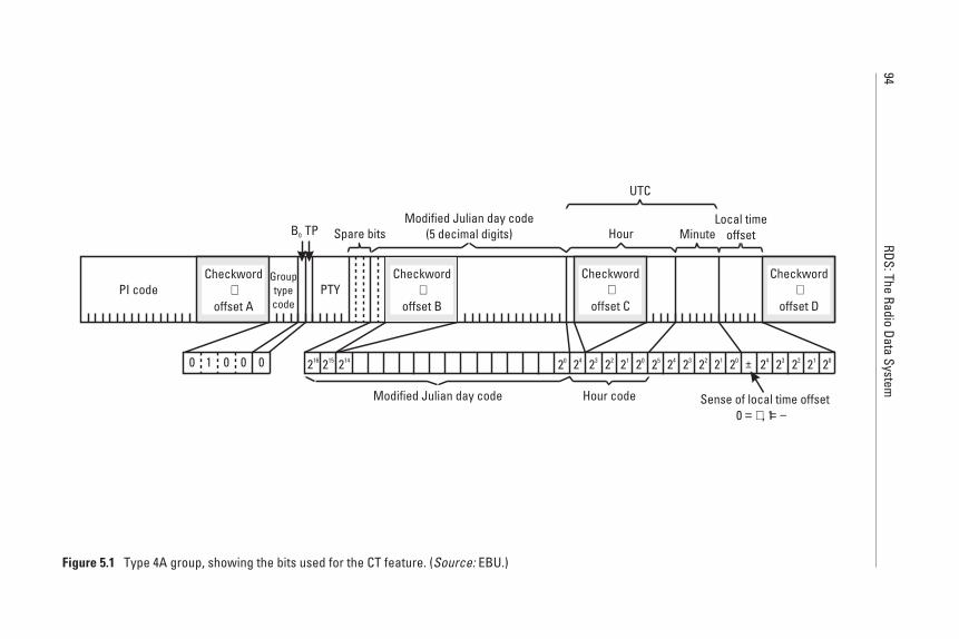
94RDS:The
RadioData
System
216
PI code PTY
B0 TP
0 1 000
Grouptypecode
Modified Julian day code(5 decimal digits)Spare bits Hour Minute
Local timeoffset
Sense of local time offset0 , 1= + = −
Hour codeModified Julian day code
215 214 20 24 23 22 21 20 25 24 23 22 21 20 24 23 22 21 20
UTC
Checkword+
offset A
Checkword+
offset B
Checkword+
offset C
Checkword+
offset D
±
Figure 5.1 Type 4A group, showing the bits used for the CT feature. (Source: EBU.)
information must be accurately set and maintained. The CT informationrelates to the epoch immediately following the start of the next group.
Clock Time is expressed as coordinated universal time (UTC) plus localtime offset. The local time offset is expressed in multiples of half hours, in therange −12 hours to +12 hours, and is coded as a six-bit binary number. Thesense of the offset is indicated by a single bit, where /0/ = positive offset (east ofzero degrees longitude) and /1/ = negative offset (west of zero degrees longi-tude). For example, 15.00 hours during the summer in the Central Europeantime zone should be expressed as 13.00 hours (UTC) and have a positive offsetof 4. Special care should be taken with the offset values when changing fromdaylight savings time (summer time) to winter time and vice versa to ensure theaccuracy of transmitted data.
The date is expressed in terms of a modified Julian day. Note that thedate changes at midnight UTC, not midnight local time. Conversion of timeand date conventions are all described in Annex G of the RDS specification EN50067:1998 [1]. It is noted that the formulae are applicable between March 1,1900 to February 28, 2100.
As CT must be accurate, it is usual for a broadcaster to synchronise theirCT transmissions to one of the national or international time references such asDCF (77.5 kHz) in Germany or MSF (60 kHz) in England. These time refer-ences are available over wide areas and relatively simple, highly reliable receiverscan be installed wherever there is an RDS encoder—to feed it with an ade-quately accurate time code signal. When accurate time reference is lost, RDSencoders should automatically suppress transmission of type 4A groups—orthey may set all bits to zero—until an accurate time has been reestablished.
Clock T is transmitted infrequently (only once per minute), and is notintended for direct display use by a receiver. The CT feature is used to set andupdate a free-running clock provided in the receiver. The receiver should usu-ally present the user with a display of the local time by calculating it from theUTC data and the offset information. It is essential that the free-running clockcontinues to function without regular type 4A groups being received. For exam-ple, a user may choose to listen to a service not providing CT information, but heor she would still expect the clock to continue to display the correct time.
RDS receivers will often be operating in areas where reception of pro-gramme services in two different time zones is possible. Some portable receivershave implemented an update on/off switch to disable automatic updatingof the clock by CT. This is done to avoid the clock showing different times,depending upon the tuned service.
The CT feature must be implemented to support some other RDSfeatures. Both Radio Paging (see Chapter 8) and Traffic Message Channel (seeChapter 7) require CT as specified in EN 50067:1998, and some Open Data
Additional Information Features 95
Applications (ODAs, see Chapter 9) may also require CT to be imple-mented [1].
5.3 Enhanced Other Networks (EON)
The EON feature was designed to allow RDS to become “intelligent,” espe-cially from the perspective of large network broadcasters (e.g., the ARD compa-nies of Germany, the BBC in the United Kingdom, and Swedish Radio) thateach operate several national radio networks.
EON information allows the updating of a considerable number of fea-tures: AF, PIN, PS, PTY, TA flag, TP identification, and linkage informationfor programme services other than that of the currently tuned service. Accord-ing to the features supported by the broadcaster and the RDS capacityavailable, some or all of this cross-reference information may be included. It isintended to allow the broadcaster to cross-reference information about all hisor her services and, if mutual agreement can be reached, also about the servicesof other broadcasters.
EON information is transmitted in type 14 groups, which has 16 variantsidentified by four bits in block 2. The information itself is carried in block 3 ofthe group, and block 4 carries the PI code of the service to which the data inblock 3 relates. This is shown in Figure 5.2. The variants may be transmitted inany order, but the repetition rate of these groups is arranged so that all data forall cross-referenced services is transmitted within a maximum of a 120-secondcycle. Not more than 20 other services should be cross-referenced by any oneservice. This limit and the maximum 120-second cycle time are important fac-tors in EON receiver design for achieving timely responses. In most areas, thetotal number of services available will not exceed 20. As a receiver changes loca-tion, the services within an RDS data stream may change, with new servicesbeing added and others removed; however, no more than 20 will ever becross-referenced by EON from any one transmitter. By keeping note of thetime since a service was referenced in EON, a receiver will be able to “mark fordeletion” services that are no longer valid.
Each EON group is entirely self-contained so that the information can beused without reference to any other group.
Although type 14A groups are usually transmitted in a regular cycle,when the status of any information on a referenced service changes (e.g., PTYor PIN changes), three or four repetitions of each appropriate group type vari-ant should be transmitted in rapid succession to assist an RDS receiver inresponding quickly to the changed information, if required (e.g., for a receiverin the PTY-STANDBY mode).
96 RDS: The Radio Data System
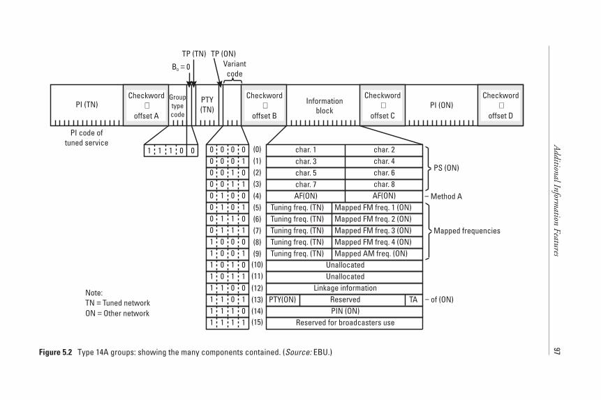
AdditionalInform
ationFeatures
97
PI (TN) PTY(TN) PI (ON)
B 00 =TP (TN)
1 1 001
Grouptypecode
Informationblock
Variantcode
(0)(1)(2)(3)(4)(5)(6)(7)(8)(9)(10)(11)(12)(13)(14)(15)
0 0 000 0 100 1 000 1 101 0 001 0 10 Tuning freq. (TN) Mapped FM freq. 1 (ON)1 1 00 Tuning freq. (TN) Mapped FM freq. 2 (ON)1 1 10 Tuning freq. (TN) Mapped FM freq. 3 (ON)0 0 01 Tuning freq. (TN) Mapped FM freq. 4 (ON)0 0 11 Tuning freq. (TN) Mapped AM freq. (ON)0 1 01 Unallocated0 1 111 0 011 0 111 1 011 1 11
TA of (ON)−
char. 1 char. 2char. 3 char. 4char. 5 char. 6char. 7 char. 8AF(ON) AF(ON)
UnallocatedLinkage information
ReservedPIN (ON)
Reserved for broadcasters use
PTY(ON)Note:TN Tuned networkON Other network
==
PS (ON)
− Method A
Mapped frequencies
TP (ON)
PI code oftuned service
Checkword+
offset A
Checkword+
offset B
Checkword+
offset C
Checkword+
offset D
Figure 5.2 Type 14A groups: showing the many components contained. (Source: EBU.)
A different mechanism is used to indicate changes in the status of TAflags of referenced services—the type 14B group (see Chapter 6).
5.3.1 Alternative Frequency Information
Alternative Frequencies of cross-referenced services are transmitted to enable anEON-capable RDS receiver to build up a complete frequency table for all theservices in memory. This allows an RDS receiver to respond immediately to arequest for another service already memorised on a preset button, even if theuser is well away from the original transmission used to source the preset infor-mation. It can do this because it will have been updated in the background,thus avoiding a PI search that may take a considerable amount of time in theincreasingly crowded FM band. There are two transmission methods specifiedto convey the AF information.
Method-A (using variant 4) is identical in structure to the Method-A cod-ing used in type 0A groups for tuned network AFs (see Chapter 3). Althoughtheoretically the number of AFs transmitted by this method may be as many as25, it is common to restrict the number to only a few.
The mapped-frequency method pairs the frequency of the tuned servicewith the corresponding frequency of the referenced service with similar cover-age areas. The tuned service frequency is transmitted as the first byte in block 3,and the frequency to which it is paired is transmitted as the second byte. Eachfrequency in the tuned network AF list is paired in turn with the correspondingfrequency for every other service being referenced. This method providesenhanced performance whereby a broadcaster transmits several services at thesame powers, from the same transmitter masts. If a receiver is providing goodreception of a service from one transmitter, it is usual to assume that switchingto another service from that same transmitter will also provide good reception.
The mapped-frequency method uses variant 5 of type 14A groups to mapone referenced service frequency to the tuned frequency. Occasionally, a fre-quency for the tuned network may be reused some distance away, and theremay be more than one corresponding frequency for one of the referencedservices. In this case, for the pairing of the second occurrence of the tunedfrequency, variant 6 is used instead of variant 5. Use of this different variantexplicitly indicates that more than one frequency is paired with this particularfrequency in the tuned network AF list. Similarly, two further variants, 7 and 8,may be used to indicate a third and fourth frequency, respectively, in the excep-tional circumstances that they are required.
The purpose of the Alternative Frequency information transmitted byEON is to ensure that a receiver maintains an up-to-date list or database ofappropriate frequencies for all of a broadcaster’s other services—not just the
98 RDS: The Radio Data System
currently tuned one. This ensures that a receiver can switch quickly to the opti-mum frequency when a listener changes the preset selection. Figure 5.3 shows aconceptual model RDS receiver with a preset button memory array and addi-tional “pool stores,” which together use AF information derived from type 0Aand type 14A groups. The PI codes and frequencies used are fictional but basedon services available in the London area.
In the case of AFs transmitted by the mapped-frequency method, eachfrequency for a service is paired with one in the AF list of the tuned service.Because the receiver is presumably using the optimum frequency for the tunedservice, it already “knows” the optimum frequency to use for the other service,should the listener choose to select the preset for it. In the case of AFs deliveredby Method-A, although no direct correspondence exists, the receiver has onlyto quickly evaluate the AF list. Method-A lists delivered by EON are likely tobe short, with no more than four or five frequencies, so evaluation of these fre-quencies can be almost instantaneous.
5.3.2 PIN and PTY Information
It is necessary to provide an EON-capable receiver with other informationto enhance the performance; the “intelligence” that EON brings and whichcan be used to allow current listening to be interrupted by information or pro-grammes from other services.
PTY is signalled in type 14A group, variant 13, and PIN in variant 14.Changes to either are indicated by immediately inserting three or four ofthe appropriate variants into the regular cycle of type 14A groups. This assiststhe receiver in responding promptly to changes, particularly when receptionconditions are not perfect, which is usually the case since the repeated variantsof type 14A groups increase the chance of “first time” decoding of the changedstatus of the feature.
When a receiver is in either PTY-STANDBY or PIN-STANDBY mode,a similar routine to that described above for EON traffic announcementsshould be followed (see Chapter 6). Switching to a programme should onlyoccur at the start of a programme. Because the start (unlike traffic announce-ments) is not signalled by using a different group type, the start can only bereliably detected by monitoring and responding to a transition of PTY code orPIN received in type 14A groups.
5.3.3 PS Information
Perhaps the simplest EON feature is the inclusion of the PS feature carried intype 14A groups, variants 0 to 3, and the coding follows closely that used in the
Additional Information Features 99
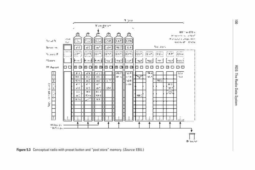
100RDS:The
RadioData
System
Figure 5.3 Conceptual radio with preset button and “pool store” memory. (Source: EBU.)
main PS feature described in Chapter 3. The eight characters are carried two ata time in these variants, so their display position is known to a receiver and theycan be built up over the 120-second cycle period, to be placed in memory asso-ciated with any presets for instant recall.
5.3.4 TP/TA Information
Type 14A groups carry information in block 2 about TP flags of cross-referencedservices in every group. Additionally, the type 14B group carries information aboutTA flags for cross-referenced services. Their use is described fully in Chapter 6.
5.4 In-House (IH) and Transparent Data Channel (TDC)
RDS can be used for completely nonprogramme-related data services, and thesehave been specified with the intention that consumer receivers do not respondin any way to their groups.
The IH data feature is reserved for data to be used solely by the serviceprovider and/or transmission operator for their own applications.
In-House data is transmitted in the 37 bits reserved in the type 6A and 6Bgroups, as shown in Figure 5.4. The content of these bits is defined unilaterallyby the service provider and/or transmission operator. The repetition rate is cho-sen to suit the application and available channel capacity.
Now that the RDS specification includes the ODA feature, the introduc-tion of new data applications previously intended for IH or TDC should beconsidered carefully for registration as ODAs in preference to using these fea-tures, because the signalling associated with ODA is more flexible [1].
The Transparent Data Channel feature allows data to be sent to any of32 addresses. The data is essentially free-format and may be for display, control,or computer applications.
TDC is transmitted in type 5 groups, as shown in Figure 5.5. Five bits inblock 2 are used for up to 32 addresses. The data is carried as 16 bits in block 3(type 5A group only) and 16 bits in block 4. The repetition rate for thesegroups must be chosen to suit the application, subject to maintaining a mini-mum rate for the basic RDS features.
5.5 Emergency Warning System (EWS)
The Emergency Warning System has been designed to take advantage of RDSFM transmissions—which already cover large broadcast service areas—to
Additional Information Features 101
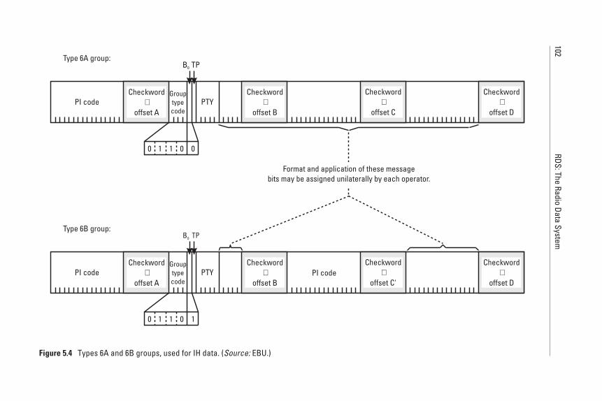
102RDS:The
RadioData
System
PI code PTY
B0 TP
B0 TP
Grouptypecode
Grouptypecode
PI code PTY PI code
Format and application of these messagebits may be assigned unilaterally by each operator.
Type 6B group:
Type 6A group:
Checkword+
offset A
Checkword+
offset A
Checkword+
offset B
Checkword+
offset B
Checkword+
offset C
Checkword+
offset C'
Checkword+
offset D
Checkword+
offset D
0 1 001
0 1 101
Figure 5.4 Types 6A and 6B groups, used for IH data. (Source: EBU.)
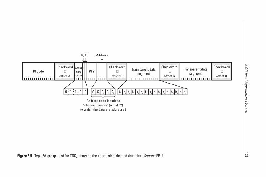
AdditionalInform
ationFeatures
103
C3 b7 b6 b5 b4 b3 b2 b1 b0b7 b6 b5 b4 b3 b2 b1b0
PI code PTY Transparent datasegment
Transparent datasegment
C2 C1 C0
Address code identities"channel number" (out of 32)
to which the data are addressed
C4
AddressB0 TP
Grouptypecode
0 1 001
Checkword+
offset A
Checkword+
offset B
Checkword+
offset C
Checkword+
offset D
Figure 5.5 Type 5A group used for TDC, showing the addressing bits and data bits. (Source: EBU.)
occasionally convey emergency status data to specialised receivers. EWS data iscarried in type 9A groups, which will be transmitted very infrequently unless anemergency or test transmission is required. The 37 bits in blocks 2, 3, and 4 areavailable for unilateral allocation in each country, as shown in Figure 5.6.
If the EWS feature is implemented, it must be signalled (say, once perminute) using type 1A groups, variant 7, and the transmission must also havethe ECC feature implemented using type 1A groups, variant 0; these are shownin Figure 3.9.
References
[1] EN 50067:1998-Specification of the Radio Data System (RDS) for VHF/FM soundbroadcasting in the frequency range from 87.5 to 108.0 MHz.
[2] EIA/NAB-National Radio Systems Committee: United States RBDS Standard version2.0, Specification of the Radio Broadcast Data System (RBDS), 1997.
104 RDS: The Radio Data System
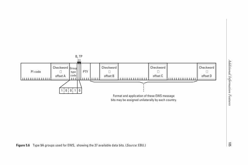
AdditionalInform
ationFeatures
105
PI code PTY
Format and application of these EWS messagebits may be assigned unilaterally by each country.
B0 TP
Grouptypecode
01 00 1
Checkword+
offset A
Checkword+
offset B
Checkword+
offset C
Checkword+
offset D
Figure 5.6 Type 9A groups used for EWS, showing the 37 available data bits. (Source: EBU.)
6Traffic Information Services
6.1 Introduction
This chapter brings together the features needed to provide both simple andmore comprehensive RDS-based traffic services. It was noted in Chapter 1 thatthe TP and TA flags have their origins in an earlier signalling system known asAutofahrer Rundfunk Information (ARI). In essence, it was designed for FMbroadcasting using a 57-kHz subcarrier to signal just two parameters, which aredirectly modelled by the TP and TA features in the RDS specification. Addi-tionally, it included the ability to indicate regionalisation, which RDS providesin the PI feature [1].
The fundamental aspects of the TP feature, which is used as a key tuningfeature, are explained fully in Chapter 3. In this chapter, the use of both trafficservice flags, TP and TA, together is explored. Then, an improved applicationof the RDS traffic service is described using the enhanced other networks(EON) feature in conjunction with the TP and TA flags by using a driver sce-nario. This scenario covers the circumstances of generating and transmitting allthe RDS features from several radio stations to make up an overall RDS trafficservice for the user.
6.2 RDS Traffic Services: Using the TP/TA Features
The RDS traffic service, which uses both TP and TA flags, is designed to allowlisteners to receive and hear traffic reports even if listening to a CD/cassette, orwith the receiver volume turned down or muted. Some receivers make use of
107
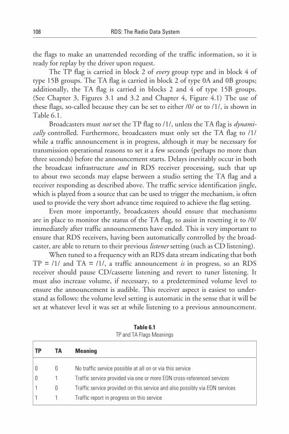
the flags to make an unattended recording of the traffic information, so it isready for replay by the driver upon request.
The TP flag is carried in block 2 of every group type and in block 4 oftype 15B groups. The TA flag is carried in block 2 of type 0A and 0B groups;additionally, the TA flag is carried in blocks 2 and 4 of type 15B groups.(See Chapter 3, Figures 3.1 and 3.2 and Chapter 4, Figure 4.1) The use ofthese flags, so-called because they can be set to either /0/ or to /1/, is shown inTable 6.1.
Broadcasters must not set the TP flag to /1/, unless the TA flag is dynami-cally controlled. Furthermore, broadcasters must only set the TA flag to /1/while a traffic announcement is in progress, although it may be necessary fortransmission operational reasons to set it a few seconds (perhaps no more thanthree seconds) before the announcement starts. Delays inevitably occur in boththe broadcast infrastructure and in RDS receiver processing, such that upto about two seconds may elapse between a studio setting the TA flag and areceiver responding as described above. The traffic service identification jingle,which is played from a source that can be used to trigger the mechanism, is oftenused to provide the very short advance time required to achieve the flag setting.
Even more importantly, broadcasters should ensure that mechanismsare in place to monitor the status of the TA flag, to assist in resetting it to /0/immediately after traffic announcements have ended. This is very important toensure that RDS receivers, having been automatically controlled by the broad-caster, are able to return to their previous listener setting (such as CD listening).
When tuned to a frequency with an RDS data stream indicating that bothTP = /1/ and TA = /1/, a traffic announcement is in progress, so an RDSreceiver should pause CD/cassette listening and revert to tuner listening. Itmust also increase volume, if necessary, to a predetermined volume level toensure the announcement is audible. This receiver aspect is easiest to under-stand as follows: the volume level setting is automatic in the sense that it will beset at whatever level it was set at while listening to a previous announcement.
108 RDS: The Radio Data System
Table 6.1TP and TA Flags Meanings
TP TA Meaning
0 0 No traffic service possible at all on or via this service
0 1 Traffic service provided via one or more EON cross-referenced services
1 0 Traffic service provided on this service and also possibly via EON services
1 1 Traffic report in progress on this service
Users can then adjust the volume level for their normal traffic announcementlistening requirements, which may be different from other listening needs.
6.3 RDS Traffic Services: Using the EON and TP/TA Features
The EON feature opens the opportunity to large network broadcasters to signalto RDS receivers that traffic announcements are available and may be receiv-able, and to provide the listener with these announcements, even though theyare being transmitted on another frequency. The basic function of EON,described in Chapter 5, is to build up a database of information about othertransmissions (over a 120-second period) and, if appropriate, to place it intoreceiver memory. In the case of the traffic service, EON is used to providedynamic information to an RDS receiver so that it can act very quickly toretune to a specific frequency; it knows from the database where a trafficannouncement is taking place.
Type 14B groups are transmitted only when there is a change in status ofthe TA flag of the referenced service. This is signalled by a minimum of four(and up to eight) type 14B groups transmitted within two seconds, with theobjective of causing rapid switching by the receiver to a traffic announcementon another service. In order to improve reception reliability, these groupsshould be spread over the two-second period in order to avoid a contiguousburst of groups being lost due to multipath propagation. Figure 6.1 shows allthe TP and TA flags in both the type 14A and 14B groups.
6.3.1 A Traffic Event Scenario
The EON traffic service therefore uses quite a complex set of interactionsbetween information being transmitted in the background, which will takesome time for an RDS receiver to acquire, and information that must be actedupon immediately. The following explanation of these interactions is based onthe situation found in the southeast of England. In this area, the BBC uses acombination of national and local services to deliver the necessary data for theRDS receiver and the local services are used to actually make traffic announce-ments on a regionalised basis. These transmissions cover county-based areas(a county is an administrative area that can normally be traversed in about60 minutes of driving time). This arrangement offers relatively locally focussedinformation delivered by traffic presenters who have good knowledge about thearea they are covering. This explanation is fictional but uses a broadly realisticidea to describe the interactions and includes some clever strategies used by thebroadcaster to achieve an economic signalling system [2].
Traffic Information Services 109
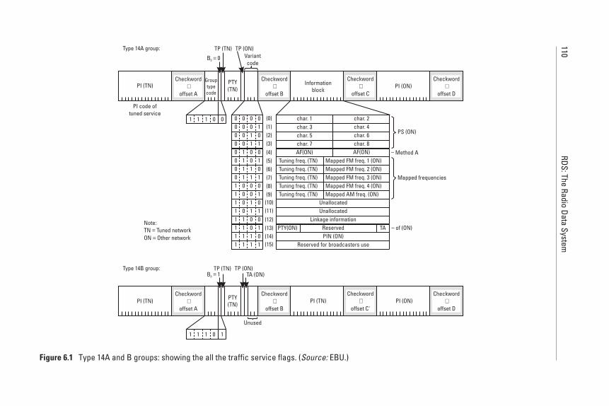
110RDS:The
RadioData
System
PI (TN)
Type 14B group:
Type 14A group:
PTY(TN)
B 10 =TP (TN)
PI (TN)
Unused
TP (ON)
1 1 101
TA (ON)
PI (TN) PTY(TN) PI (ON)
PI (ON)
B 00 =TP (TN)
1 1 001
Grouptypecode
Informationblock
Variantcode
(0)(1)(2)(3)(4)(5)(6)(7)(8)(9)(10)(11)(12)(13)(14)(15)
0 0 000 0 100 1 000 1 101 0 001 0 10 Tuning freq. (TN) Mapped FM freq. 1 (ON)1 1 00 Tuning freq. (TN) Mapped FM freq. 2 (ON)1 1 10 Tuning freq. (TN) Mapped FM freq. 3 (ON)0 0 01 Tuning freq. (TN) Mapped FM freq. 4 (ON)0 0 11 Tuning freq. (TN) Mapped AM freq. (ON)0 1 01 Unallocated0 1 111 0 011 0 111 1 011 1 11
TA of (ON)−
char. 1 char. 2char. 3 char. 4char. 5 char. 6char. 7 char. 8AF(ON) AF(ON)
UnallocatedLinkage information
ReservedPIN (ON)
Reserved for broadcasters use
PTY(ON)Note:TN Tuned networkON Other network
==
PS (ON)
− Method A
Mapped frequencies
TP (ON)
PI code oftuned service
Checkword+
offset A
Checkword+
offset B
Checkword+
offset C
Checkword+
offset D
Checkword+
offset A
Checkword+
offset B
Checkword+
offset C'
Checkword+
offset D
Figure 6.1 Type 14A and B groups: showing the all the traffic service flags. (Source: EBU.)
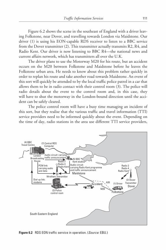
Figure 6.2 shows the scene in the southeast of England with a driver leav-ing Folkstone, near Dover, and travelling towards London via Maidstone. Ourdriver (1) is using his EON-capable RDS receiver to listen to a BBC servicefrom the Dover transmitter (2). This transmitter actually transmits R2, R4, andRadio Kent. Our driver is now listening to BBC R4—the national news andcurrent affairs network, which has transmitters all over the U.K.
The driver plans to use the Motorway M20 for his route, but an accidentoccurs on the M20 between Folkstone and Maidstone before he leaves theFolkstone urban area. He needs to know about this problem rather quickly inorder to replan his route and take another road towards Maidstone. An event ofthis sort will quickly be attended to by the local traffic police patrol in a car thatallows them to be in radio contact with their control room (3). The police willradio details about the event to the control room and, in this case, theywill have to shut the motorway in the London-bound direction until the acci-dent can be safely cleared.
The police control room will have a busy time managing an incident ofthis sort, but they realise that the various traffic and travel information (TTI)service providers need to be informed quickly about the event. Depending onthe time of day, radio stations in the area use different TTI service providers,
Traffic Information Services 111
South Eastern England
(1) DriverAccident(2) Dover
Transmitter
(3) Policecontrol room
(5) BBCKent studios
(6)Wrotham Transmitter
Dover
Folkstone
Maidstone
A20
M20
Radio 2Radio 4
Radio Kent
Radio 2Radio 4Radio Kent
Dial-up link:modems
Audio circuit: carryingtraffic announcement
PCM link:carrying audioand data
Audio circuit:carrying Radio Kent programmeand traffic announcement
LondonBroadcasting
House
(4) BBCTravel Centre (7) Central RDS
Computer
Figure 6.2 RDS EON traffic service in operation. (Source: EBU.)
including the BBC Travel Centre (4), based at Broadcasting House in London,and the Automobile Association Roadwatch service. In order to keep this exam-ple clear, it is assumed that the BBC Travel Centre is informed about the acci-dent by the police control room. The information may be sent to the trafficpresenter by dial-up modem link, fax, or a phone call, but this will dependupon operational circumstances.
So, now the BBC Travel Centre is aware of the accident and they will talkto the Radio Kent on-air studio to agree on the timing for a suitable trafficannouncement to be broadcast. This announcement may be held for a fewminutes until a suitable programme break occurs and, until a scheduled trafficannouncement time slot comes up, or it may be given urgent status. In anycase, the Radio Kent presenter will hand over control to the traffic presenter,who then can give the traffic announcement to Radio Kent listeners. It isalready known that there is a Radio Kent transmitter near Dover, and there areothers around the county to ensure good coverage, so the driver should bewithin range of a transmitter that will carry this announcement.
When a traffic announcement is being made with RDS implemented, theRadio Kent transmitters must have their TA flag set to /1/, but this will onlyhelp the user who is already tuned to a Radio Kent transmission, as described inSection 6.2. In this case, the driver is listening to Radio 4. However, he hadpreset his EON-capable RDS receiver to EON traffic service reception mode,so the receiver has already started to build up a database in memory from theBBC R4 service. When the driver started his journey, he was tuned to the BBCR4 service from the Dover transmitter (2). He may have already unknowinglymade use of the RDS AF and PI features and been retuned to the Wrothamtransmitter (6), also transmitting BBC R4. It does not matter which signal isbeing received, because both are carrying the background EON information.By now, the EON-capable RDS receiver has acquired considerable informationabout the BBC transmissions in the Kent area; indeed, it would know every-thing necessary in 120 seconds if good reception conditions are present. In thiscase, it needs to have acquired the data specifically about Radio Kent and eitherupdated a preset button-related memory or placed the information in a poolstore (see Figure 5.3).
Now, it is necessary to go back and look at the signalling systems used toprovide both dynamic TA flag control and dynamic control of the EON type14B groups. Firstly, assume that just as the starting traffic “identification jin-gle” is played, the Radio Kent on-air studio sends a command signal to theBBC central RDS computer (7) to indicate the situation: “BBC Kent trafficannouncement starting now.” (A message of this type has to be generatedby every on-air studio that is designed to control the system so that trafficannouncements can still be voiced by service providers from outside the BBC,
112 RDS: The Radio Data System
who are feeding their audio into BBC on-air studios.) The central RDS com-puter receives this message and places it into a complete database of all BBCRDS data. From this database, the computer is able to generate appropriateupdate messages for RDS encoders wherever they may be. This is done by asuitable addressing system (see Chapter 11 for more details of studio to encodercommunications and the UECP). These update messages are sent to all possibletransmitters, including the Wrotham transmitter site in North Kent (6).
6.3.2 Clever Signalling
At this point, it is desirable to take a short diversion from the story and discussthe data circuits that are used, because this is where a clever use of RDS comesin. Between BBC Broadcasting House and the main transmitter sites such asWrotham (6), there are wideband digital distribution circuits capable of carry-ing many audio channels and data. Thus, the Wrotham site has transmittersfor the national services, fed by high-quality audio from London, and dynamicRDS is directly controlled from the central RDS computer. But the BBC RadioKent transmitters at Wrotham and Dover, giving the county coverage acrossKent, do not have direct control from the central RDS computer. For example,the Dover transmitter receives RDS update data from off-air RDS signals byusing an off-air receiver tuned to BBC R2 and then decoding the EON dataabout Radio Kent. The RDS decoder is connected to the RDS encoder, andthis in turn is commanded to change the TA flag on the local Radio Kent trans-mission. Thus, the cost of data circuits is greatly reduced by this on-air signal-ling technique.
6.3.3 Update Messages Content
Now, consider the update messages and their content. The update commandfrom the central RDS computer instructs encoders referencing Radio Kentas an “other network” to set the TA flag in Radio Kent EON groups, whichresults in the required transmission of up to eight type 14B groups within twoseconds. This data is carried on-air to the Radio Kent transmitter at Dover, ofcourse, and it is also transmitted on BBC R4 from Wrotham (6). In addition, itis transmitted on BBC R4 from Dover (2), which is a rebroadcast transmitter.
As a result, the driver whose EON-capable RDS receiver is tuned to BBCR4 somewhere in the Kent area and receiving an RDS data stream with EONinformation receives a specific vector command. The type 14B groups vector areceiver to a particular PI code, probably held in memory; if it is memorised,either in preset button memory or in a pool store memory, then associatedalternative frequencies (AFs) will already have been noted for particular signal
Traffic Information Services 113
strength/quality. Thus, appropriate frequencies for Radio Kent are alreadyknown, and the EON receiver can just check the known frequencies for suit-able signal strength and switch to the traffic announcement if the PI codematch is satisfied. Once tuned directly to a Radio Kent transmitter for a trafficannouncement, the receiver monitors the TA flag in the type 0 and 15B groupsuntil it is set to /0/, whereupon it retunes to the original frequency and volumelevel setting.
Thus, the driver is able to hear the traffic announcement from BBCRadio Kent even though he had been tuned to BBC R4, and after theannouncement the receiver is retuned back to BBC R4. He heard aboutthe accident and diverted onto the A20 main road!
6.3.4 Receiver Reactions
An EON-capable RDS receiver will be controlled to give the listener arequested response by commands from the broadcaster. So, it must be certainthat it does this well, and a number of steps should be followed when set intothe EON traffic mode.
Cross-referenced services that provide traffic announcements are indi-cated as such by setting the TP (ON) bit (in block 2) to /1/ in the tuned servicetype 14A groups. This bit identifies the cross-referenced service as a trafficannouncement service to the receiver, the purpose of which is to ensure thatdata for this service is stored in receiver memory prior to it being required for atraffic announcement.
The traffic announcement is on the service referenced by the PI code inblock 4 of the type 14B group. The receiver should check the signal strength ofthe stored frequency for that service. If unacceptable, it should check, in turn,any others in the AF list for that PI and tune to the best frequency, if any othersare receivable in that area. It should also check that the PI code matches that inblock 4 of the type 14 B group, and then wait for a few seconds to establish thatthe TA flag has been set to /1/.
When a traffic announcement takes place, the broadcaster sends up toeight type 14B groups with the TA (ON) bit set to /1/ in rapid succession.Although a receiver only requires a single type 14B group to switch to a trafficannouncement on the service indicated by the PI code in block 4, sending sev-eral groups increases the likelihood of detection by the receiver. To allow thereceiver some response time to switch, these type 14 B groups should begin afew seconds prior to the start of the traffic announcement’s spoken content. Ofcourse, the TA flag in type 0A (or 0B and 15B) groups of the service providingthe traffic announcement must also be set.
114 RDS: The Radio Data System
At the end of the traffic announcement, the TA flag in the trafficannouncement providing service must be promptly cleared (reset to /0/).Optionally, type 14B groups with TA (ON) set to /0/ may be sent. They areonly used by the broadcaster for internal network management purposes, whichmay be part of the complex scenario painted before to reduce the number ofdedicated circuits within the transmission systems, to facilitate all the com-mands required.
References
[1] CENELEC, EN 50067:1998-Specifications of the Radio Data System (RDS.) forVHF/FM broadcasting, European Committee for Electrical Standardisation (CENELEC),35B rue de Stassart, B-1050 Brussels, April 1998.
[2] Howe, P., “RDS-The Engineering Concept,” BBC Radio, 1990
Traffic Information Services 115
7Intelligent Transport Systems andRDS-TMC
7.1 Introduction
Since the European Commission has chosen the RDS-TMC as a priority tech-nology to be introduced for the provision of traffic and travel information onthe major roads within the European Union member states, those involved intransport telematics have given much attention to RDS. In this chapter, weexplain the strategic and policy issues that surround RDS-TMC—the markettrends for telematics equipment in general and RDS-TMC in particular. Theresulting human/machine interface problems and safety aspects that this posesare also covered.
The objectives to be achieved, and the history of RDS-TMC develop-ment (which started some 15 years ago), are analysed. We can see that in spiteof this long development effort, RDS-TMC is not yet meeting the expectationsthat the politicians had for this technology.
The standardisation and institutional implementation issues, togetherwith the basic principles of RDS-TMC coding, are explained, with some exam-ples that help to better understand the technical detail of how RDS-TMCworks. We show aspects of existing RDS-TMC receivers and where the prob-lems are in their implementation.
Finally, we refer to alternative technologies and services that make it pos-sible to see RDS-TMC in a much wider context—that it is in a long-termdevelopment leading to a significant improvement of the infrastructuresrequired to provide better information services to the mobile road users.
117
7.2 Strategic and Policy Issues
In Europe, Japan, and the United States, huge transport telematics technologyresearch and development programmes have been underway for several years.Their main focus is to coordinate the deployment of intelligent transport sys-tems, which requires that a certain number of technical standards be developed.On the European level, this is undertaken by CEN (TC 278), CENELEC, andETSI, and on a world level by the International Standards Organisation (ISO,TC 204), IEC, and the International Telecommunication Union (ITU).The term “telematics” is derived from the terms “telecommunications” and“informatics,” and describes the fact that information processed by means ofcomputers is being distributed to assist users to better cope with different trans-port modes for which the complexity, interdependence, and density is everincreasing. In other words, information and communication technologies areincreasingly used to improve the delivery of general interest services [1].Figure 7.1 shows one view of the telematics scene.
Traffic and travel information (TTI) is one of the general interest servicesthat is being developed under these programmes. The use of RDS technologyto deliver TTI messages within the European Union has long been recognisedby the European Commission. This is in line with the resolutions of theEuropean Conference of Ministers of Transport (ECMT) and the Council ofthe European Union, who have recommended, as a priority action, since 1995,the introduction of a new language-independent TTI service calledRDS-TMC, where TMC means Traffic Message Channel [2, 3].
7.3 Market Trends for Telematics Terminal Equipment
The equipment we are particularly interested in is the RDS-TMC receiver—aspart of a car radio designed to present improved traffic and travel informationservices to the end user. We are also interested in navigational units that can beautonomous or connected (also called dual-mode) to information services oper-ated via mobile telephones (GSM), or RDS-TMC receivers for the dynamicupdating of the route guidance information used on a particular trip.
The market potential for navigational systems can simply be consideredas gigantic, and the evolution becomes obvious from the figures published in[5] and reproduced in Table 7.1.
We can note several trends. In Japan, this market is already very big, butthe European and U.S. markets are following. In Europe today, the biggestmarket is Germany where two-thirds of all upper-class car models are alreadyfactory-fitted with navigational systems.
118 RDS: The Radio Data System

In 1997/98 alone in Japan, many of the navigational systems sold alreadyhad functionality for dynamic updating via the Vehicle Information and Com-munication System (VICS) using DARC FM-multiplex data broadcast tech-nology. In Europe, similar systems first came onto the market in 1997, using
Intelligent Transport Systems and RDS-TMC 119
Table 7.11995–2000, Number of Annually Sold Car Navigational Units
1995 1996 1997 1998 1999 2000
In Europe 12,000 50,000 ,155,000 1,350,000 1,700,000 1,000,000
In Germany 12,000 40,000 ,110,000 1,200,000 1,320,000 1,500,000
In USA 5,000 20,000 ,200,000 1,500,000 — —
In Japan 600,000 800,000 1,000,000 1,200,000 1,500,000 —
GPS locating satellite
ARI/RDS-DAB traffic message radio
Mobile radio telephoneservice, indiv. traffic info
ADAC head office
Breakdown assistance disposition
Figure 7.1 The German automobile club ADAC’s view of a number of upcoming transporttelematics road information services, among which is RDS-TMC. (Source: ADAC.)
RDS-TMC for the dynamic updating; however, GSM and digital audio broad-casting (DAB) are likely to be used as well before the year 2000.
We can also note another trend. In the past, traffic information receiverswere essentially car radios for which there was a significant aftermarket—sup-ported by more than 50 different consumer electronic manufacturers, mainlyfrom Europe and the Far East, supplying a wide range of products.
Since RDS has been on the market, car manufacturers have tended moreand more to integrate the car radio in conjunction with multifunctional dis-plays on the dashboard, and these will be increasingly used together with othertelematics functionality. Additionally, they order original equipment manufac-turer (OEM) equipment meeting their own interface requirements, opposingany standardisation of these interfaces.
Most recently, the German mobile telephone provider Mannesmann-Autocom acquired VDO, a large company that manufactures vehicle instru-ments and car dashboards. Then it acquired Philips Car Systems, one of themajor car radio manufacturers and also an important supplier of telematic ter-minals and navigational systems. All this indicates that the aftermarket for allthese products may gradually shrink and that a number of different telematicsystems, as accepted by the market, will coexist through telematics equipmentthat is delivered with the car to the end user. On the other hand, due to therapid progress in telematics technology, it is reasonable to assume that the pre-dicted lifetime of the terminal equipment will be significantly shorter than thatof a car (11.5 years, on average, in Germany). This trend opens new opportuni-ties for the shrinking aftermarket.
In Germany in 1996, 60% of the three million GSM telephones alreadyin use were, according to a study made by the German automobile industryassociation VDA, in one way or another also used in cars, which means that1.7 million cars in Germany are equipped with mobile communication termi-nals. Some 96% of the units sold in 1996 were handheld units, of which 70%were supplied with optional equipment for fixed car installation. There is also atrend to integrate a GSM telephone with the car radio [6].
In 1994, the TELTEN project of the European Commission estimatedthe probable market penetration for RDS-TMC receivers for two scenarios: anoptimistic one and a pessimistic one. Estimated market penetration in motorvehicles within Europe for RDS-TMC receivers was, in the optimistic case, 2%in 1998, 10% in 2000, and 61% in 2005. In the pessimistic case, estimateswere 1% in 1998, 5% in 2000 and 48% in 2005. The latter, translated intoabsolute figures, predicts for RDS-TMC a European market of 31,000 units
120 RDS: The Radio Data System
in 1998, 235,000 units in the year 2000 and 2.3 million units in the year2005 [7].
7.4 Safety Aspects of Presentation of Traffic and TravelInformation in Moving Vehicles
As more and more in-vehicle services come to the market, equipment add-onsmight not be as thoroughly researched as equipment fitted in factories. There isalso reason for concern that multiple in-vehicle services might jeopardise safety.There can be many different devices that communicate, and that in turnwill present new information to the driver, distracting attention from the trafficaround the vehicle on the road. For example, using a handheld GSM telephonewhile driving a car is generally considered to be dangerous. A study conductedin 1997 for the German automobile club ADAC shows that even using ahands-free fixed telephone distracts a lot the driver’s attention from the traffic,and statistics about driver behaviour have indicated that all sorts of mistakes arebeing caused by distracted drivers [8].
As we have seen, telephones, navigational devices, and RDS-TMC unitswill be increasingly used. In such a case, designers will have to give particularattention to human/machine interface aspects. It will be necessary to integrateseveral communication functions into the same unit; also, the same displayin the dashboard for presenting the driver with stress-free information will beused. Driver information will be presented in sequence, and not simultane-ously, about several of these functions: GSM information services to be calledup or based on automatic call-back, navigational information, and RDS-TMCmessage presentation.
More and more types of in-vehicle equipment thus require interoperabil-ity studies to be conducted so that guidelines can be established to reduce stressand distraction to the motorist when driving. Although the ECMT and the ECare fairly active in researching these issues, clear European guidelines on thesesafety issues and related certification and labelling mechanisms did not existbefore 1998 for transport telematics terminal equipment. However, in theUnited Kingdom, there is already a draft for development prepared bythe Department of Transport, and in Germany, the public and private sectorshave agreed on a code of practice on the functions and security of in-vehiclesystems [9–11]. During 1998, this matter has received urgent EC-supportedinvestigation and has become a key research issue.
Intelligent Transport Systems and RDS-TMC 121
7.5 RDS-TMC
7.5.1 Objectives to be Achieved
The objective of RDS-TMC is to broadcast traffic and travel information(TTI) messages on VHF/FM broadcast transmissions using RDS. The mes-sages are digitally coded in such a way that they are language-independent. Thecoding also permits users to receive only those messages that are relevant totheir needs. Thus, it may be possible for a tourist to travel, for example, fromLondon to Rome, through Belgium, Germany, Switzerland, France, and Italy,always getting the traffic announcements via RDS-TMC in his or her own lan-guage, the location codes being on a smart card that was purchased in London.But for this objective to be achieved, apart from a European standard specifyingthe system, a large number of harmonised administrative arrangements have tobe agreed to among the countries concerned.
The TTI messages that are distributed will, of course, be conveyed to avariety of media that may include traffic announcements presented via speechsynthesis in the language required. The messages will be filtered on the basis ofcriteria derived from the needs of the end user (e.g., location, direction, route).This filtering is aimed at enabling the user to receive only relevant information,selected from all the messages that are available on an RDS-TMC service at anygiven time.
The importance of filtering is demonstrated in this example. Given themaximum capacity of RDS-TMC, it will be possible to transmit about 300 dif-ferent messages per hour. If the same messages were spoken and each only took15 seconds, the total announcement time would be 75 minutes—an obviousinformation overload! In addition, RDS-TMC messages could be used toprovide assistance for route planning, use of alternative transport facilities androutes, and dynamic updating of electronic maps and systems used for naviga-tional aids.
In other words, RDS-TMC will be provided to simply give assistance tothe question of how to get safely and efficiently from point A to point B.
7.5.2 History of the RDS-TMC Development
The possibility of using digitally coded traffic information within the RDS datastream was first mentioned by Bosch/Blaupunkt in 1984 at the Eurotravelconference in Grado, Italy. Bosch/Blaupunkt immediately started the technicaldevelopment in Germany, and Philips in the Netherlands followed shortlyafterwards. One year later, the European Association of Consumer ElectronicsManufacturers, known then as Eurotech (now European Association of
122 RDS: The Radio Data System
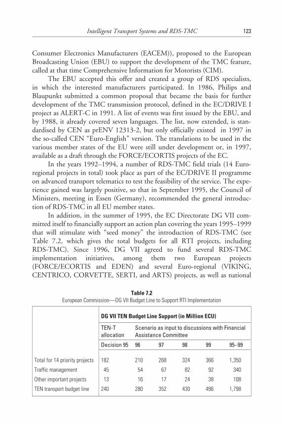
Consumer Electronics Manufacturers (EACEM)), proposed to the EuropeanBroadcasting Union (EBU) to support the development of the TMC feature,called at that time Comprehensive Information for Motorists (CIM).
The EBU accepted this offer and created a group of RDS specialists,in which the interested manufacturers participated. In 1986, Philips andBlaupunkt submitted a common proposal that became the basis for furtherdevelopment of the TMC transmission protocol, defined in the EC/DRIVE Iproject as ALERT-C in 1991. A list of events was first issued by the EBU, andby 1988, it already covered seven languages. The list, now extended, is stan-dardised by CEN as prENV 12313-2, but only officially existed in 1997 inthe so-called CEN “Euro-English” version. The translations to be used in thevarious member states of the EU were still under development or, in 1997,available as a draft through the FORCE/ECORTIS projects of the EC.
In the years 1992–1994, a number of RDS-TMC field trials (14 Euro-regional projects in total) took place as part of the EC/DRIVE II programmeon advanced transport telematics to test the feasibility of the service. The expe-rience gained was largely positive, so that in September 1995, the Council ofMinisters, meeting in Essen (Germany), recommended the general introduc-tion of RDS-TMC in all EU member states.
In addition, in the summer of 1995, the EC Directorate DG VII com-mitted itself to financially support an action plan covering the years 1995–1999that will stimulate with “seed money” the introduction of RDS-TMC (seeTable 7.2, which gives the total budgets for all RTI projects, includingRDS-TMC). Since 1996, DG VII agreed to fund several RDS-TMCimplementation initiatives, among them two European projects(FORCE/ECORTIS and EDEN) and several Euro-regional (VIKING,CENTRICO, CORVETTE, SERTI, and ARTS) projects, as well as national
Intelligent Transport Systems and RDS-TMC 123
Table 7.2European Commission—DG VII Budget Line to Support RTI Implementation
DG VII TEN Budget Line Support (in Million ECU)
TEN-Tallocation
Scenario as input to discussions with FinancialAssistance Committee
Decision 95 96 97 98 99 95–99
Total for 14 priority projects 182 210 268 324 366 1,350
Traffic management 45 54 67 82 92 1,340
Other important projects 13 16 17 24 38 1,108
TEN transport budget line 240 280 352 430 496 1,798
projects that all together involve Austria, Belgium, Denmark, Finland, France,Germany, Italy, the Netherlands, Portugal, Spain, Sweden, and the UnitedKingdom. This led to many regional RDS-TMC implementations on impor-tant sections of the Trans-European Road Network (TERN), concerning themain trunk roads in the in European Union.
The year 1997 was when the first RDS-TMC introductions started in afew EU member states (or parts of them), on a preoperational basis in mostcases. The others have firm plans to follow this plan up to the year 2000. Asa priority, these new RDS-TMC services intend first of all to cover all majorroads belonging to the TERN.
Since a public and open service is generally expected to become availableall over the European Union, it is hoped within the EC that public/privatepartnerships (i.e., partnerships between road authorities, police, automobileclubs, industry, broadcasters, etc.) will become possible within the EU memberstates, and that these states will then work together actively towards achievingRDS-TMC implementation, supporting the policy addressed in the resolutionfrom the Council of EU Ministers.
7.5.3 The Pan-European Service Objective and the Memoranda ofUnderstanding
The European Commission requested, in line with the European CouncilResolutions of September 1995 and March 1997, that EU member statesshould promote the introduction of RDS-TMC and implement their servicesaccording to the proposed prestandards to ensure continuity andinteroperability.
In the autumn of 1997, to better achieve this objective, the EuropeanCommission launched two Memoranda of Understanding (MoU), one encour-aging the introduction of RDS-TMC services and the other recommending theDATEX protocol for communication between traffic information centres.Both were to be further developed and implemented following the recommen-dations of the EDEN project for transborder TTI data exchange.
Previous to these MoUs, the European Commission pursued the objec-tive of providing to the people of Europe, a free Pan-European TTI service(PES) covering the traffic situation on the Trans-European Road Network(TERN) using RDS-TMC as the transmission mode. However, during thedrafting of the MoUs, the term PES was dropped to favour a number of differ-ent but compatible services and without insisting that the services should befree to the end user on a European scale.
124 RDS: The Radio Data System
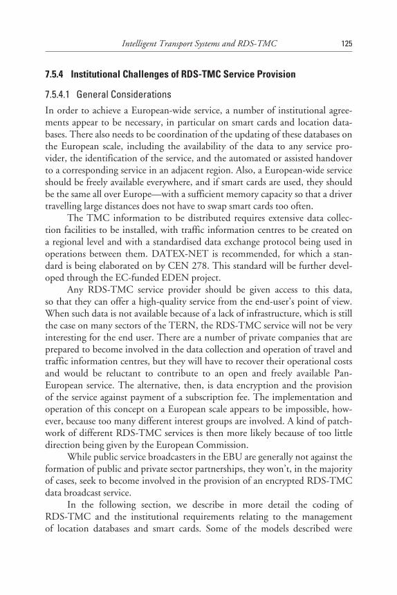
7.5.4 Institutional Challenges of RDS-TMC Service Provision
7.5.4.1 General ConsiderationsIn order to achieve a European-wide service, a number of institutional agree-ments appear to be necessary, in particular on smart cards and location data-bases. There also needs to be coordination of the updating of these databases onthe European scale, including the availability of the data to any service pro-vider, the identification of the service, and the automated or assisted handoverto a corresponding service in an adjacent region. Also, a European-wide serviceshould be freely available everywhere, and if smart cards are used, they shouldbe the same all over Europe—with a sufficient memory capacity so that a drivertravelling large distances does not have to swap smart cards too often.
The TMC information to be distributed requires extensive data collec-tion facilities to be installed, with traffic information centres to be created ona regional level and with a standardised data exchange protocol being used inoperations between them. DATEX-NET is recommended, for which a stan-dard is being elaborated on by CEN 278. This standard will be further devel-oped through the EC-funded EDEN project.
Any RDS-TMC service provider should be given access to this data,so that they can offer a high-quality service from the end-user’s point of view.When such data is not available because of a lack of infrastructure, which is stillthe case on many sectors of the TERN, the RDS-TMC service will not be veryinteresting for the end user. There are a number of private companies that areprepared to become involved in the data collection and operation of travel andtraffic information centres, but they will have to recover their operational costsand would be reluctant to contribute to an open and freely available Pan-European service. The alternative, then, is data encryption and the provisionof the service against payment of a subscription fee. The implementation andoperation of this concept on a European scale appears to be impossible, how-ever, because too many different interest groups are involved. A kind of patch-work of different RDS-TMC services is then more likely because of too littledirection being given by the European Commission.
While public service broadcasters in the EBU are generally not against theformation of public and private sector partnerships, they won’t, in the majorityof cases, seek to become involved in the provision of an encrypted RDS-TMCdata broadcast service.
In the following section, we describe in more detail the coding ofRDS-TMC and the institutional requirements relating to the managementof location databases and smart cards. Some of the models described were
Intelligent Transport Systems and RDS-TMC 125
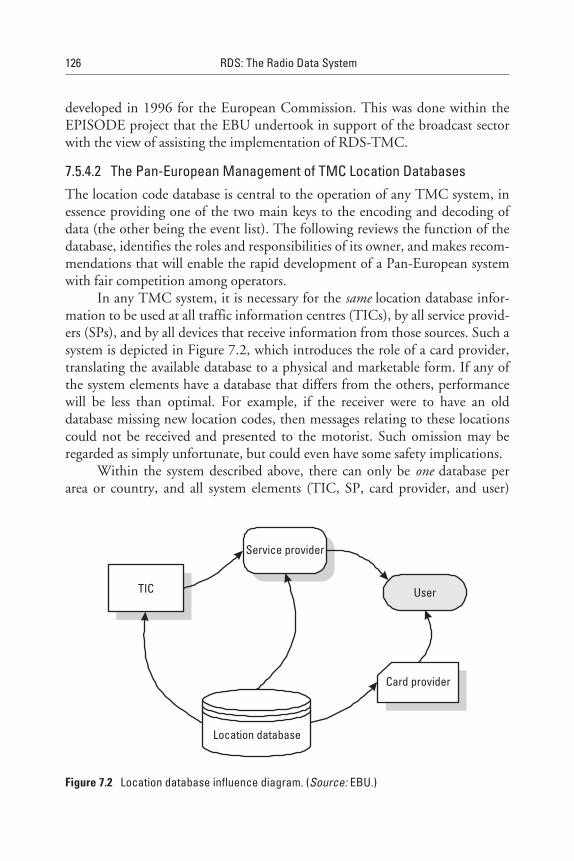
developed in 1996 for the European Commission. This was done within theEPISODE project that the EBU undertook in support of the broadcast sectorwith the view of assisting the implementation of RDS-TMC.
7.5.4.2 The Pan-European Management of TMC Location DatabasesThe location code database is central to the operation of any TMC system, inessence providing one of the two main keys to the encoding and decoding ofdata (the other being the event list). The following reviews the function of thedatabase, identifies the roles and responsibilities of its owner, and makes recom-mendations that will enable the rapid development of a Pan-European systemwith fair competition among operators.
In any TMC system, it is necessary for the same location database infor-mation to be used at all traffic information centres (TICs), by all service provid-ers (SPs), and by all devices that receive information from those sources. Such asystem is depicted in Figure 7.2, which introduces the role of a card provider,translating the available database to a physical and marketable form. If any ofthe system elements have a database that differs from the others, performancewill be less than optimal. For example, if the receiver were to have an olddatabase missing new location codes, then messages relating to these locationscould not be received and presented to the motorist. Such omission may beregarded as simply unfortunate, but could even have some safety implications.
Within the system described above, there can only be one database perarea or country, and all system elements (TIC, SP, card provider, and user)
126 RDS: The Radio Data System
TIC
Service provider
User
Card provider
Location database
Figure 7.2 Location database influence diagram. (Source: EBU.)

must derive their individual databases from this one source. It is not possiblefor more than one location database to be used within this system, whereas it ispossible for TICs, service providers, card providers, and receiver manufacturersto operate competitively. Clearly, the owner of the location database is, andmust be, in a monopoly situation.
If fair competition and reasonable access is to be given to all operators,providers, and manufacturers, it is imperative that strict regulations and guide-lines be imposed on database owners. We believe that such databases should beowned by nonprofit organisations, preferably by public authorities, and main-tained by contractors. Costs may be offset by reasonable charges for acquisitionof the database, which may be licensed for a period (to maintain system integ-rity) to operators, service providers, and card providers.
The task of the location database owner is to provide a fully maintaineddatabase, accessible on fair and equal terms to all who may request it and isupdated at regular and declared intervals. In order to ensure that all systemcomponents are kept to the latest possible standard, it will be necessary fordatabase owners to declare in advance when a new update is to be made avail-able so that, for example, card providers may ensure that mass production issuitably synchronised.
The Pan-European vision of TMC foresees that a traveller can buy or renta smart card in Italy that has location codes for London but with eventspronounced in Italian. Such a card needs to be assembled using informationderived from the U.K. database. This principle extends all over Europe, and itis clear that each database needs to be made very widely available.
Technical standards for information exchange need to be developed, suchthat any potential operator/supplier can obtain information from any databaseowner. Possibly the best way of achieving such interchangeability is to use opendatabase communication (ODBC) protocols, which will permit operators toderive whole or defined subsets of a database at ease—for example, just loca-tions in the northeast of France.
As memory sizes increase, card providers will wish to market productsthat cover larger geographical areas, and it will be possible and necessary toinclude locations derived from more than one location database. Clearly, thereare distinct advantages in encouraging database owners to synchronise theirupdates so that it is possible to manufacture products containing the latestinformation from several sources. Such a situation is depicted in Figure 7.3.
With such an aim in mind, a nonprofit-making European databaseexchange organisation should be considered that coordinates and collects infor-mation from individual database owners and makes this available to all—sub-ject to appropriate licences being issued.
Intelligent Transport Systems and RDS-TMC 127
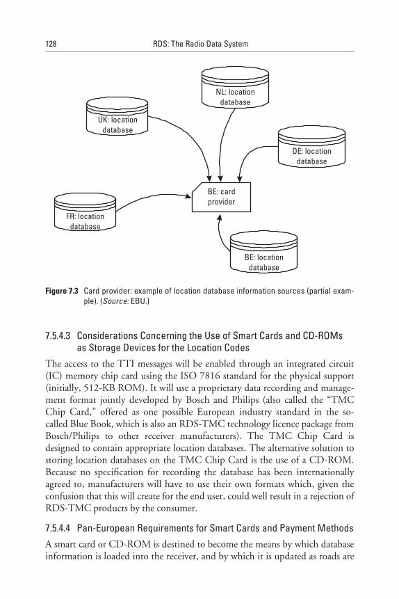
7.5.4.3 Considerations Concerning the Use of Smart Cards and CD-ROMsas Storage Devices for the Location Codes
The access to the TTI messages will be enabled through an integrated circuit(IC) memory chip card using the ISO 7816 standard for the physical support(initially, 512-KB ROM). It will use a proprietary data recording and manage-ment format jointly developed by Bosch and Philips (also called the “TMCChip Card,” offered as one possible European industry standard in the so-called Blue Book, which is also an RDS-TMC technology licence package fromBosch/Philips to other receiver manufacturers). The TMC Chip Card isdesigned to contain appropriate location databases. The alternative solution tostoring location databases on the TMC Chip Card is the use of a CD-ROM.Because no specification for recording the database has been internationallyagreed to, manufacturers will have to use their own formats which, given theconfusion that this will create for the end user, could well result in a rejection ofRDS-TMC products by the consumer.
7.5.4.4 Pan-European Requirements for Smart Cards and Payment MethodsA smart card or CD-ROM is destined to become the means by which databaseinformation is loaded into the receiver, and by which it is updated as roads are
128 RDS: The Radio Data System
UK: locationdatabase
FR: locationdatabase
BE: locationdatabase
DE: locationdatabase
NL: locationdatabase
BE: cardprovider
Figure 7.3 Card provider: example of location database information sources (partial exam-ple). (Source: EBU.)
improved. In the following, the function of these products is reviewed. Therequirements for payment in a genuine Pan-European system are identified,and a simple and effective mechanism is proposed for deriving an income fromthe sale or rental of devices that may be distributed by or on behalf of serviceproviders who cannot attract public support.
Each TMC receiver needs to have access to both a location code databaseand an event database coded in the user’s language. Without these databases,the data stream arriving is meaningless. Each user will wish to acquire a series ofdatabases, covering the areas in which he or she will travel. These are expectedto be distributed in the form of a smart card, CD-ROM, or some otherexchange media.
It is expected that smart cards or CD-ROMs will be supplied by a varietyof providers, formatted to appropriate standards using data derived fromnational databases. In order to ensure that a high quality of service is main-tained, it is imperative for these storage devices to have a version number andan expiration date, guaranteeing that out-of-date versions are no longer usable.
Each and every service provider will need to fund the costs of service pro-vision in some way. In many countries, this will be by public grant. However,some countries are unwilling to support these services, and thus a mechanismmust be included to generate a cash flow to pay for the service. This will enablea genuine Pan-European TMC service to be realised.
The simplest means of providing payment for a service is to deriveincome from the sale of cards to the user. These cards will need to be replacedperiodically in order to ensure consistent service quality, and thus a source ofregular income can be realised.
The profit on the sale or rental of cards may be used to finance the costsof obtaining the databases used, and to finance the service provider offering thedata being delivered to the user.
It is expected that in many areas an RDS-TMC service may be availablefrom more than one service provider (e.g., in the United Kingdom throughboth automobile clubs, the Automobile Association (AA), and the RoyalAutomobile Club (RAC)), permitting competition to push quality up and costsdown. The RDS-TMC standards require broadcasting a service identificationcode to be within the data stream that will enable a receiver to locate the serviceoperated by a preferred provider. To enable such a system to operate to thebenefit of the consumer, cards need to have the ability to carry one or moreservice identification (SId) codes (rather in the same manner as a GSM carddoes today), allowing a TMC receiver to automatically find the required serv-ice(s). Relationships could be established between service and card providers,permitting one card to give access to more than one service, as shown inFigure 7.3.
Intelligent Transport Systems and RDS-TMC 129
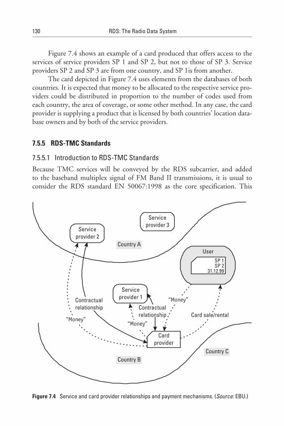
Figure 7.4 shows an example of a card produced that offers access to theservices of service providers SP 1 and SP 2, but not to those of SP 3. Serviceproviders SP 2 and SP 3 are from one country, and SP 1is from another.
The card depicted in Figure 7.4 uses elements from the databases of bothcountries. It is expected that money to be allocated to the respective service pro-viders could be distributed in proportion to the number of codes used fromeach country, the area of coverage, or some other method. In any case, the cardprovider is supplying a product that is licensed by both countries’ location data-base owners and by both of the service providers.
7.5.5 RDS-TMC Standards
7.5.5.1 Introduction to RDS-TMC StandardsBecause TMC services will be conveyed by the RDS subcarrier, and addedto the baseband multiplex signal of FM Band II transmissions, it is usual toconsider the RDS standard EN 50067:1998 as the core specification. This
130 RDS: The Radio Data System
“Money”“Money”
“Money”Contractualrelationship Contractual
relationship
Serviceprovider 2
Serviceprovider 1
Serviceprovider 3
Country A
Country BCountry C
Cardprovider
Card sale/rental
UserSP 1SP 2
31.12.99
Figure 7.4 Service and card provider relationships and payment mechanisms. (Source: EBU.)

specification, when first published in 1990 and updated in 1992, already con-tained references to the RDS-TMC feature, mentioning both type 8A groupsand a variant of the type 1A group that would be used for TMC identification.
However, the needs of a TMC service were not well defined at that stage,and work over recent years by CEN TC 278 SWG 4.1 and by the EC-fundedFORCE Project has clarified the situation, resulting in the need to define moreaspects of RDS-TMC in additional standards.
7.5.5.2 The Specification of the RDS System (CENELEC EN 50067:1998): theCore RDS Standard
The upgraded RDS standard EN 50067:1998 was developed by joint work inthe RDS Forum and CENELEC TC 207, using a very wide range of experts.This version of the standard now fully includes the new open data application(ODA) feature (see Chapter 9), originally suggested for RDS-TMC purposes.It also includes specific references and “hooks” to ENV 12313-1: June 1997,where necessary. The former RDS-TMC references were kept to leave the dooropen for non-ODA implementations of RDS-TMC in the short term, butit is recommended that these implementations no longer are recommended tobe maintained.
7.5.5.3 The Coding Protocol for RDS-TMC (ENV 12313-1): the So-CalledALERT-C Protocol
The coding protocol for RDS-TMC is defined in ENV 12313-1, which wasaccepted by voting within CEN in early 1996, but was the subject of an adden-dum and corrigendum. This addendum was originally issued in June 1996,mainly in response to comments from CEN TC 278. In view of this, ENV12313-1, Version 2.20, dated September 1996 ,was redrafted to include all pre-vious editorial changes noted in the addendum and corrigendum, and this hasbeen subsequently further improved to become ENV 12313-1, Version 3.0,dated June 1997. Therefore, this should now be taken as the main standarddescribing the so-called, ALERT-C protocol. This document contains boththe TMC message protocol and the RDS-TMC-related coding used by theRDS-TMC feature, using type (1A), 3A, and 8A groups to convey the TMCmessages with event and location codes and network and service layerinformation.
7.5.5.4 Event and Information Codes for RDS-TMC (prENV 12313-2): theALERT-C Event List
The event and information codes for RDS-TMC required by the ALERT-Cprotocol are specified in prENV 12313-2, FINAL DRAFT, dated May 1997.Although this standard does not actually require any further work to operate a
Intelligent Transport Systems and RDS-TMC 131
service, it is seen as necessary to adopt versions for each European country/lan-guage. For example, in the United Kingdom, it is normal to describe distancesin miles, but distance is described quite differently in other countries (in kilo-metres), so an agreed upon definition is useful to help uniform message genera-tion and TMC decoder presentation.
7.5.5.5 Location Referencing Rules for RDS-TMC (prENV 278/7/3/0005DRAFT)
Location referencing has been one of the most contentious issues, and rules forRDS-TMC are available as a draft dated March 1997. However, progress onCEN TC 278 SWG 7.3 has been rather slow and many workers are now awarethat there needs to be considerable effort put into resolving the outstandingissues. In particular, location database development which had begun using aformer draft has shown that considerable variation of interpretation results, andthe FORCE Project has established a subgroup (“Interpretation of the LocationReferencing Rules”) to resolve these problems.
7.5.6 Data Formats of the TMC Feature
Coding of TMC makes use of the ODA concept. Two coding protocols exist:ALERT-C, which will generally be used for the Pan-European service (PES)and which is described in ENV 12313-1, and ALERT-Plus with ALERT-C,which will be used in France and of which, in 1997, only a draft specificationexisted (prENV 278/4.1.1/0004).
The PES will operate in two different ODAs:
• The first ODA, dealing with ALERT-C only;
• The second ODA, allowing operation of a mixed ALERT-Pluswith ALERT-C service described in the draft specification prENV278/4/1.1.1/0004 or updates of it.
For this reason, the ALERT-C structure using type 8A groups is the samefor both types of protocol—both applications have the same application grouptype 8A but a different application identifier code (AID). Table 7.3 illustratesthe situation.
Figure 7.5 shows the format of type 8A groups when used forRDS-TMC. This group carries the TMC messages, service provider name, andtuning information.
The coding of ALERT-C messages is shown in Figure 7.6.
132 RDS: The Radio Data System
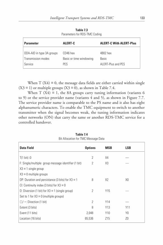
When T (X4) = 0, the message data fields are either carried within single(X3 = 1) or multiple groups (X3 = 0), as shown in Table 7.4.
When T (X4) = 1, the 8A groups carry tuning information (variants 6to 9) or the service provider name (variants 4 and 5), as shown in Figure 7.7.The service provider name is comparable to the PS name and it also has eightalphanumeric characters. To enable the TMC equipment to switch to anothertransmitter when the signal becomes weak, the tuning information indicatesother networks (ON) that carry the same or another RDS-TMC service for acontrolled handover.
Intelligent Transport Systems and RDS-TMC 133
Table 7.3Parameters for RDS-TMC Coding
Parameter ALERT-C ALERT-C With ALERT-Plus
ODA-AID in type 3A groups CD46 hex 4B02 hex
Transmission modes Basic or time windowing Basic
Service PES ALERT-Plus and PES
Table 7.4Bit Allocation for TMC Message Data
Data Field Options MSB LSB
T(1 bit) :0 2,04 2 X4 —
F: Single/multiple group message identifier (1 bit)
X3 = 1 single group
X3 = 0 multiple groups
2,0 42 X3 —
DP: Duration and persistance (3 bits) for X3 = 1
CI: Continuity index (3 bits) for X3 = 0
2,0 48 X2 X0
D: Diversion (1 bit) for X3 = 1 (single group)
Set to 1 for X3 = 0 (multiple groups)
2,0 42 Y15 —
+ / −: Direction (1 bit) 2,0 42 Y14 —
Extent (3 bits) 2,0 48 Y13 Y11
Event (11 bits) 2,048 Y10 Y0
Location (16 bits) 65,536 Z15 Z0
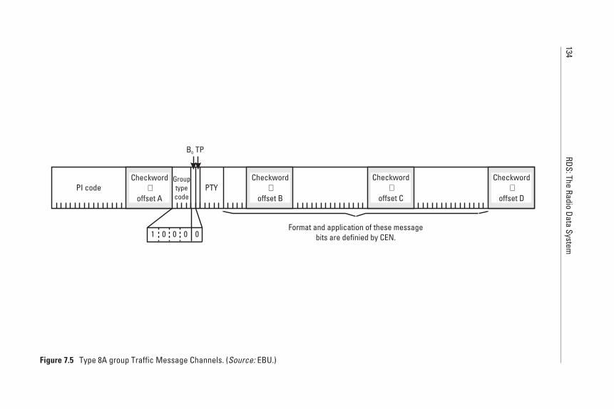
134RDS:The
RadioData
System
PI code PTY
Format and application of these messagebits are definied by CEN.
Checkword+
offset A
Checkword+
offset B
Checkword+
offset C
Checkword+
offset D
B0 TP
Grouptypecode
0 0 001
Figure 7.5 Type 8A group Traffic Message Channels. (Source: EBU.)
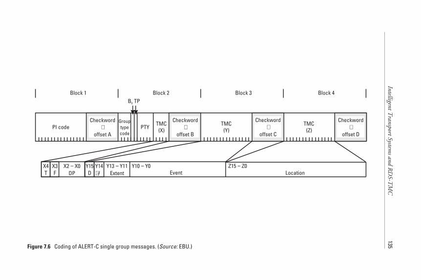
IntelligentTransportSystem
sandR
DS-T
MC
135
PI code PTY TMC(X)
TMC(Y)
TMC(Z)
Block 1 Block 2 Block 3 Block 4
X2 X0DP−X4
TX3F
Y15D
Y14/+ −
Y13 Y11Extent
−Event
Y10 Y0−Location
Z15 Z0−
Checkword+
offset A
Checkword+
offset B
Checkword+
offset C
Checkword+
offset D
B0 TP
Grouptypecode
Figure 7.6 Coding of ALERT-C single group messages. (Source: EBU.)
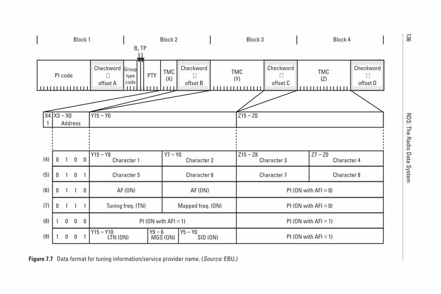
136RDS:The
RadioData
System
1X4 X3 X0− Y15 Y0− Z15 Z0−
Address
(4) 0 1 0 0 Character 1 Character 2 Character 3 Character 4
(5) 0 1 0 1 Character 5 Character 6 Character 7 Character 8
(6) 0 1 1 0 AF (ON) AF (ON) PI (ON with AFI 0)=
(7) 0 1 1 1 Tuning freq. (TN) Mapped freq. (ON) PI (ON with AFI 0)=
(8) 1 0 0 0 PI (ON with AFI 1)= PI (ON with AFI 1)=
(9) 1 0 0 1 LTN (ON) SID (ON) PI (ON with AFI 1)=MGS (ON)
Y7 Y0− Z7 Z0−Y15 Y8−
Y9 6− Y5 Y0−Y15 Y10−
Z15 Z8−
PI code PTY TMC(X)
TMC(Y)
TMC(Z)
Block 1 Block 2 Block 3 Block 4
Checkword+
offset A
Checkword+
offset B
Checkword+
offset C
Checkword+
offset D
B0 TP
Grouptypecode
Figure 7.7 Data format for tuning information/service provider name. (Source: EBU.)
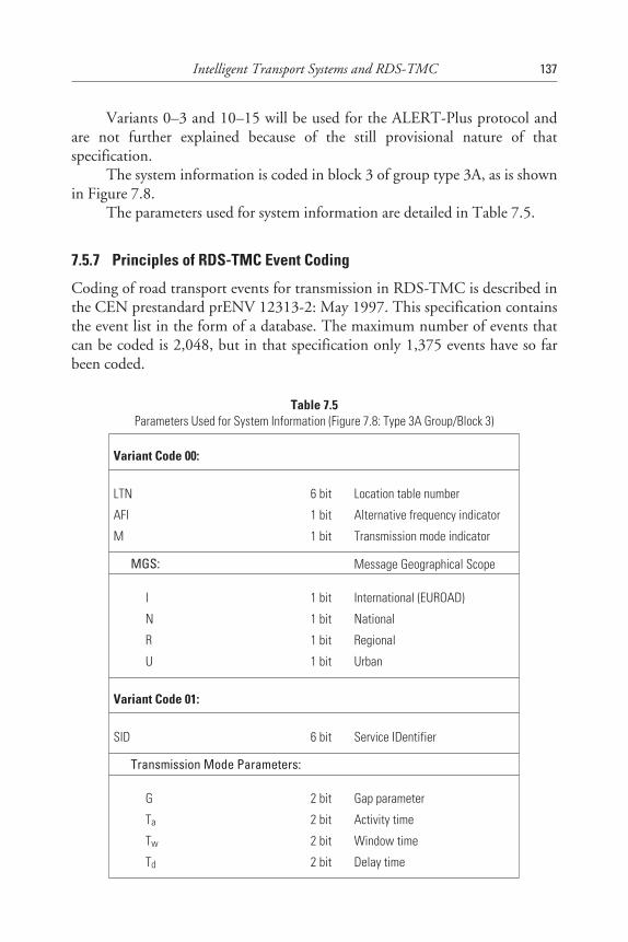
Variants 0–3 and 10–15 will be used for the ALERT-Plus protocol andare not further explained because of the still provisional nature of thatspecification.
The system information is coded in block 3 of group type 3A, as is shownin Figure 7.8.
The parameters used for system information are detailed in Table 7.5.
7.5.7 Principles of RDS-TMC Event Coding
Coding of road transport events for transmission in RDS-TMC is described inthe CEN prestandard prENV 12313-2: May 1997. This specification containsthe event list in the form of a database. The maximum number of events thatcan be coded is 2,048, but in that specification only 1,375 events have so farbeen coded.
Intelligent Transport Systems and RDS-TMC 137
Table 7.5Parameters Used for System Information (Figure 7.8: Type 3A Group/Block 3)
Variant Code 00:
LTN 6 bit Location table number
AFI 1 bit Alternative frequency indicator
M 1 bit Transmission mode indicator
MGS: Message Geographical Scope
I 1 bit International (EUROAD)
N 1 bit National
R 1 bit Regional
U 1 bit Urban
Variant Code 01:
SID 6 bit Service IDentifier
Transmission Mode Parameters:
G 2 bit Gap parameter
Ta 2 bit Activity time
Tw 2 bit Window time
Td 2 bit Delay time
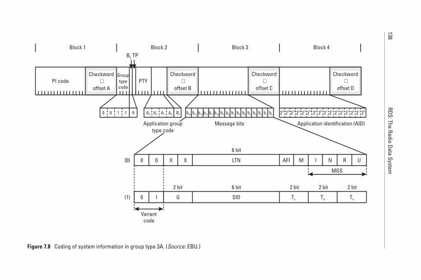
138RDS:The
RadioData
System
0 0 011
Message bits Application identification (AID)
A3 A2 B0A0A1 b0b15 b14 b13 b12 b11 b10 b9 b8 b7 b6 b5 b4 b3 b2 b1 215 214 213 212 211 210 29 28 27 26 25 24 23 22 21 20
U0(0)
(1)
0 X X LTN AFI M I N R
6 bit
MGS
0 1 G SID Ta Tw Td
6 bit2 bit 2 bit 2 bit 2 bit
Variantcode
PI code PTY
Block 1 Block 2 Block 3 Block 4
Checkword+
offset A
Checkword+
offset B
Checkword+
offset C
Checkword+
offset D
B0 TP
Grouptypecode
Application grouptype code
Figure 7.8 Coding of system information in group type 3A. (Source: EBU.)
To describe an event, we want to use an example: A passenger car hadan accident and when the car parked at the roadside waiting for assistance toarrive, two dogs jumped out and ran on the motorway. With the ongoing traf-fic, the owners were not able to catch them and bring them back into the car.Passengers from other cars passing by noticed the hazard and informed thetraffic service of the automobile association of the incident. The automobileassociation forwarded the message to the regional broadcaster, who sent out amessage about this event using the appropriate location code. The message senthas the code 922, meaning “animals on roadway.” The coding system does notpermit specifying that the animals were dogs, or what kind of dogs. The samecode is used for one or several animals and independent of the kind of ani-mal—mouse, cat, dog, crocodile or elephant.
Because there are 1,375 possible codes, the database has been structuredinto 31 categories (also called update classes) with the view of assisting the mes-sage generation operator in quickly finding the right code—in this case, 922.This message belongs to category 13: Dangerous situations.
Table 7.6 contains the list of event categories used and also how manyevents are foreseen in each of these categories. One can see from the list that theediting software used by the operator for TMC coding can then be hierarchi-cally structured along the line of these categories.
7.5.8 Principles of RDS-TMC Location Reference Coding
Most messages provide information about a location (e.g., a stretch of road, anintersection, or a region) and they refer to it by using a location reference. Thisis an identifier that can be interpreted without ambiguity by the receiving sys-tem. In RDS-TMC, locations are predefined and precoded, and the codes arestored in location code tables. The maximum number of codes in one table isdetermined by the field length for location codes in RDS-TMC; that is, 16 bits,which corresponds to 65,536 possible codes. The disadvantage of these tables isthat they need to be created and maintained as was explained above, and thereceiving system must use exactly the same table as the one used for encoding ofthe message. Otherwise, the message is not receivable.
The rules for location reference coding are specified in CEN prestandardprENV 278/7/3/0005: May 1997. These rules apply to ALERT-C messagesonly. ALERT-Plus uses a different system. Because of the provisional nature ofALERT-Plus in 1997, no further reference is made to that particular codingmethod, and all details that follow are extracted from the prestandard and applythus to ALERT-C messages only.
Predefined locations are referenced by their location code, which is thetabular address of a number of prestored location details. Each table of stored
Intelligent Transport Systems and RDS-TMC 139
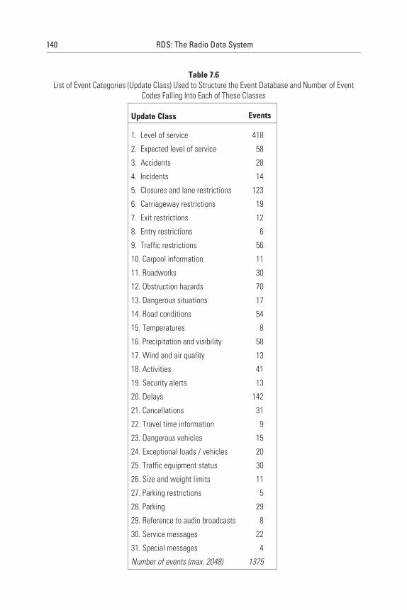
140 RDS: The Radio Data System
Table 7.6List of Event Categories (Update Class) Used to Structure the Event Database and Number of Event
Codes Falling Into Each of These Classes
Update Class Events
1. Level of service 418
2. Expected level of service 58
3. Accidents 28
4. Incidents 14
5. Closures and lane restrictions 123
6. Carriageway restrictions 19
7. Exit restrictions 12
8. Entry restrictions 6
9. Traffic restrictions 56
10. Carpool information 11
11. Roadworks 30
12. Obstruction hazards 70
13. Dangerous situations 17
14. Road conditions 54
15. Temperatures 8
16. Precipitation and visibility 58
17. Wind and air quality 13
18. Activities 41
19. Security alerts 13
20. Delays 142
21. Cancellations 31
22. Travel time information 9
23. Dangerous vehicles 15
24. Exceptional loads / vehicles 20
25. Traffic equipment status 30
26. Size and weight limits 11
27. Parking restrictions 5
28. Parking 29
29. Reference to audio broadcasts 8
30. Service messages 22
31. Special messages 4
Number of events (max. 2048) 1375
locations must be given a unique location table number by one unique agencyin each country or state. A country code (note: RDS-TMC uses the RDS coun-try codes given in Appendix G) identifies the agency responsible for locationreference coding and which one defined the location table and its number.
Many location references extend through several adjacent areas or roadsections. The concept of primary and secondary locations is then used to indi-cate the extremities of the affected sections without having to list all the inter-vening places. For example, if an accident occurs at km 14.2 on the E15 (A26road in France) and the resulting queue extends back to km 10.9, the situationlocation can be defined as E15, “km 14.2–10.9," where km 14.2 is defined asthe primary location and km 10.9 is the secondary location. The primary loca-tion is taken to be where the cause of the problem can be found, whenever acause can be pinpointed geographically. However, both primary and secondarylocations will lie on the same road.
For the primary location, the location reference is the nearest downstreamlocation in the direction of travel. The secondary location is indicated in termsof extent; that is, the number of steps back along the road through other prede-fined locations. Alternatively, a distance marker may be used.
All location codes belong to a unique location table. Within any particu-lar location code table, each location has one unique number in the range1–63,487. The other 2,048 numbers are reserved for EUROAD, an agreedupon concept used for coding messages to international travellers on the TransEuropean Road Network (TERN).
RDS-TMC uses a hierarchical structure of predefined locations. A systemof pointers provides upward references to higher level locations containing thespecified location. For example, Kent would have an upward area reference tosoutheast England, which will be upwards referenced to the United Kingdom,then the British Isles, then Europe.
Junction 25 on the M1 motorway in the United Kingdom would have asection of route referenced to a motorway segment (e.g., Leicester–Sheffield).This segment will then be referenced upwards to the whole road (i.e., themotorway M1).
Also, Junction 25 on a motorway may be offset to Junction 26 in thepositive direction, and to Junction 24 in the negative direction.
In many cases, events affecting road traffic cover a number of locations,such as where an accidents results in long tailbacks. The ALERT-C protocoldefines such occurrences by addressing the location of the accident as the pri-mary location, then identifying the end of the tailback by using the directionand extent fields. These fields consist of four bits in total: one direction bit andthree extent bits. The direction bit indicates the queue growth and not thedirection of traffic flow. The extent bits identify the number of locations along
Intelligent Transport Systems and RDS-TMC 141
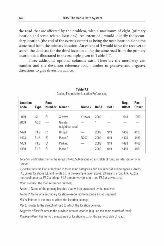
the road that are affected by the problem, with a maximum of eight (primarylocation and seven related locations). An extent of 1 would identify the secon-dary location (the end of the event’s extent) as being the next location along thesame road from the primary location. An extent of 3 would force the receiver tosearch the database for the third location along the same road from the primarylocation as is illustrated in the example given in Table 7.7.
Three additional optional columns exist. These are the motorway exitnumber and the deviation reference road number in positive and negativedirections to give diversion advice.
142 RDS: The Radio Data System
Table 7.7Coding Example for Location Referencing
LocationCode Type
RoadNumber Name 1 Name 2 Ref A Ref L
Neg.Offset
Pos.Offset
949 L3 E1 X-town Y-town 2009 — 948 950
2009 A6.2 — Greaterneighbourhood
— 1 — — —
4420 P3.2 E1 Bridge — 2009 949 4456 4423
4423 P1.3 E1 Place A N207 2009 949 4420 4459
4459 P3.3 E1 Parking — 2009 949 4423 4460
4460 P1.3 E1 Place B — 2009 949 4459 4461
Location code: Identifier in the range 0 to 65,536 describing a stretch of road, an intersection or aregion;
Type: Defines the kind of location in three main categories and a number of sub-categories: Areas(A), Linear locations (L), and Points (P). In the example given above, L3 means a road link, A6.2 ametropolitan area, P3.2 a bridge, P1.3 a motorway junction, and P3.3 a service area;
Road number: The road reference number;
Name 1: Name of the primary location that will be presented by the receiver;
Name 2: Name of a secondary location—required to describe a road segment;
Ref A: Pointer to the area to which the location belongs;
Ref L: Pointer to the stretch of road to which the location belongs;
Negative offset: Pointer to the previous area or location (e.g., on the same stretch of road);
Positive offset: Pointer to the next area or location (e.g., on the same stretch of road).
7.5.9 Example for Constructing an RDS-TMC Message
The message:
Motorway A9 Munich-Nuremberg, direction Nuremberg, stationary traf-fic between exit Pfaffenhofen and motorway interchange Holledau. Devia-tion recommended via the U31 from exit Pfaffenhofen,
requires the following message elements, which are given here as decimal num-bers and which will then be binary coded:
• Duration: 0 for no specific duration specified;
• Diversion: 1 for deviation being recommended;
• Direction of event: 1 for negative;
• Extent of event: 2 for two locations backward in the location code list;
• Event: 101 for stationary traffic;
• Location code: 12735 for motorway interchange Holledau.
The coded type 8A group for this example is shown in Figure 7.9.The corresponding part of the location code list is given in Table 7.8. For
simplification of understanding, all numbers are given as decimal numbers, butin reality these are coded as binary numbers.
7.5.10 RDS Encoders and the EBU/UECP
After editing the RDS-TMC messages in the broadcasting house, they are sentto the transmitter or the transmitter network for insertion into the RDS datastream. This task is achieved with the help of RDS encoders that receive themessages in a specified format, as shown in Figure 7.10.
RDS encoders certainly need software adaptation to allow RDS-TMC tobe implemented as it is now specified. One of the protocols of interest from theEuropean point of view is the EBU Universal Encoder Communication Proto-col (UECP), which required an urgent enhancement to include all the newlydefined possibilities specified.
The EBU document SPB 490 (version 5.1) is an upgrade to achieve thesame enhanced functionality (especially for ODA and TMC) as offered by EN500067:1998 and the most recent RDS-TMC specifications. This work wasstarted within the RDS Forum in 1996 and completed during 1997.
Intelligent Transport Systems and RDS-TMC 143
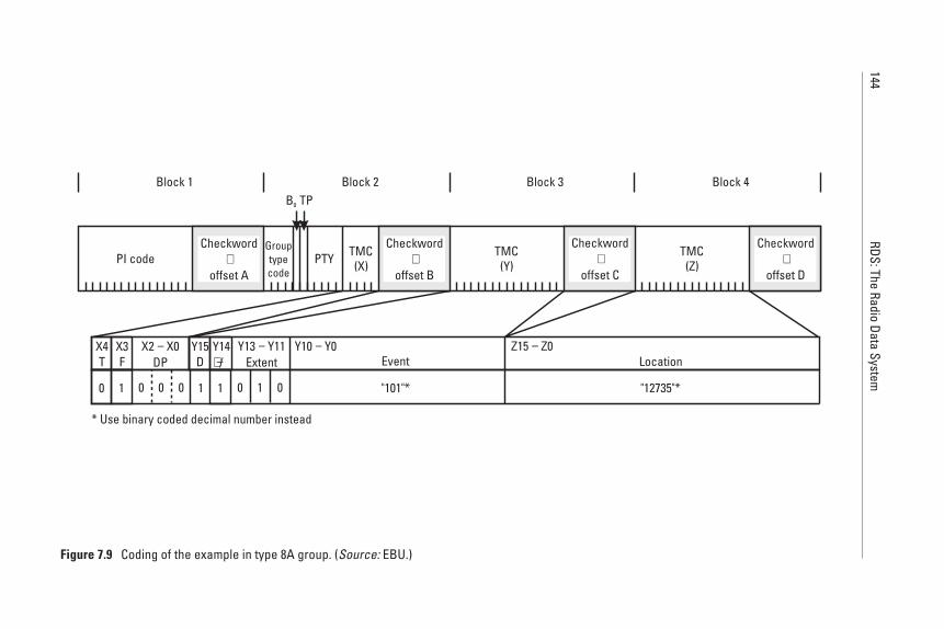
144RDS:The
RadioData
System
* Use binary coded decimal number instead
0 1 "101"* "12735"*0 0 0 1 01 1 0
PI code PTY TMC(X)
TMC(Y)
TMC(Z)
Block 1 Block 2 Block 3 Block 4
X2 X0DP−X4
TX3F
Y15D
Y14/+ −
Y13 Y11Extent
−Event
Y10 Y0−Location
Z15 Z0−
Checkword+
offset A
Checkword+
offset B
Checkword+
offset C
Checkword+
offset D
B0 TP
Grouptypecode
Figure 7.9 Coding of the example in type 8A group. (Source: EBU.)
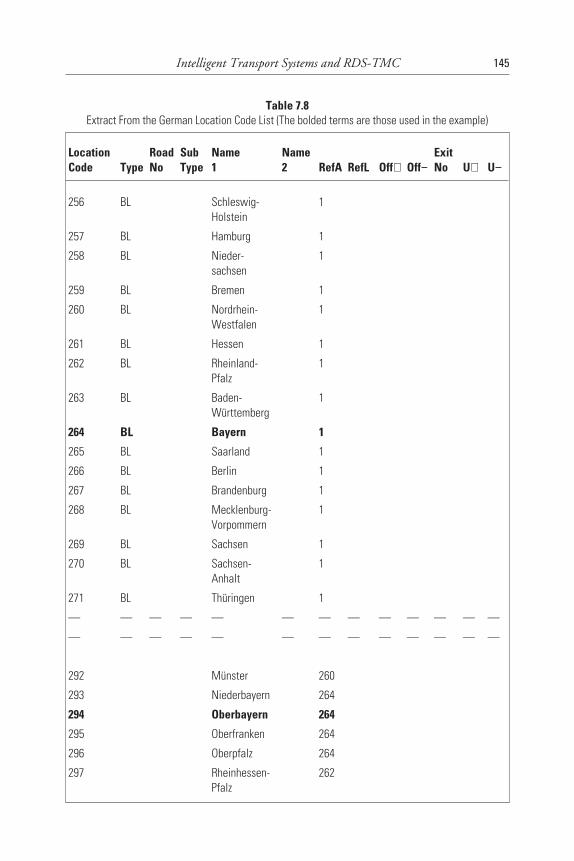
Intelligent Transport Systems and RDS-TMC 145
Table 7.8Extract From the German Location Code List (The bolded terms are those used in the example)
LocationCode Type
RoadNo
SubType
Name1
Name2 RefA RefL Off+ Off−
ExitNo U+ U−
256 BL Schleswig-Holstein
1
257 BL Hamburg 1
258 BL Nieder-sachsen
1
259 BL Bremen 1
260 BL Nordrhein-Westfalen
1
261 BL Hessen 1
262 BL Rheinland-Pfalz
1
263 BL Baden-Württemberg
1
264 BL Bayern 1
265 BL Saarland 1
266 BL Berlin 1
267 BL Brandenburg 1
268 BL Mecklenburg-Vorpommern
1
269 BL Sachsen 1
270 BL Sachsen-Anhalt
1
271 BL Thüringen 1
— — — — — — — — — — — — —
— — — — — — — — — — — — —
292 Münster 260
293 Niederbayern 264
294 Oberbayern 264
295 Oberfranken 264
296 Oberpfalz 264
297 Rheinhessen-Pfalz
262
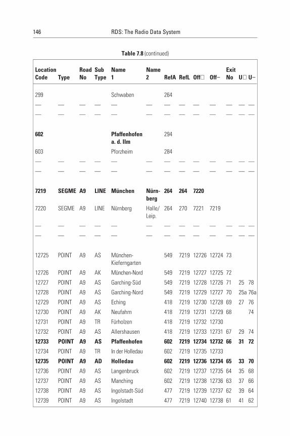
146 RDS: The Radio Data System
Table 7.8 (continued)
LocationCode Type
RoadNo
SubType
Name1
Name2 RefA RefL Off+ Off−
ExitNo U+ U−
299 Schwaben 264
— — — — — — — — — — — — —
— — — — — — — — — — — — —
602 Pfaffenhofena. d. Ilm
294
603 Pforzheim 284
— — — — — — — — — — — — —
— — — — — — — — — — — — —
7219 SEGME A9 LINE München Nürn-berg
264 264 7220
7220 SEGME A9 LINE Nürnberg Halle/Leip.
264 270 7221 7219
— — — — — — — — — — — — —
— — — — — — — — — — — — —
12725 POINT A9 AS München-Kieferngarten
549 7219 12726 12724 73
12726 POINT A9 AK München-Nord 549 7219 12727 12725 72
12727 POINT A9 AS Garching-Süd 549 7219 12728 12726 71 25 78
12728 POINT A9 AS Garching-Nord 549 7219 12729 12727 70 25a 76a
12729 POINT A9 AS Eching 418 7219 12730 12728 69 27 76
12730 POINT A9 AK Neufahrn 418 7219 12731 12729 68 74
12731 POINT A9 TR Fürholzen 418 7219 12732 12730
12732 POINT A9 AS Allershausen 418 7219 12733 12731 67 29 74
12733 POINT A9 AS Pfaffenhofen 602 7219 12734 12732 66 31 72
12734 POINT A9 TR In der Holledau 602 7219 12735 12733
12735 POINT A9 AD Holledau 602 7219 12736 12734 65 33 70
12736 POINT A9 AS Langenbruck 602 7219 12737 12735 64 35 68
12737 POINT A9 AS Manching 602 7219 12738 12736 63 37 66
12738 POINT A9 AS Ingolstadt-Süd 477 7219 12739 12737 62 39 64
12739 POINT A9 AS Ingolstadt 477 7219 12740 12738 61 41 62
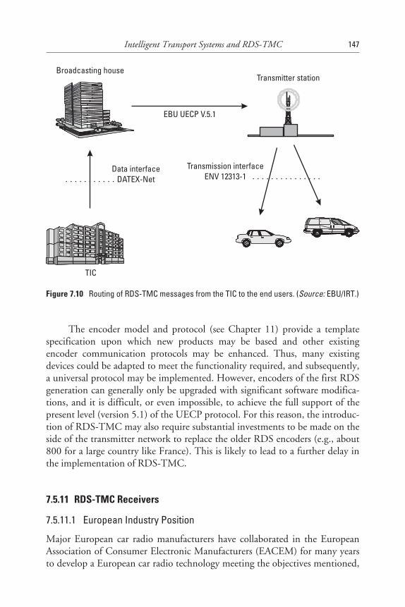
The encoder model and protocol (see Chapter 11) provide a templatespecification upon which new products may be based and other existingencoder communication protocols may be enhanced. Thus, many existingdevices could be adapted to meet the functionality required, and subsequently,a universal protocol may be implemented. However, encoders of the first RDSgeneration can generally only be upgraded with significant software modifica-tions, and it is difficult, or even impossible, to achieve the full support of thepresent level (version 5.1) of the UECP protocol. For this reason, the introduc-tion of RDS-TMC may also require substantial investments to be made on theside of the transmitter network to replace the older RDS encoders (e.g., about800 for a large country like France). This is likely to lead to a further delay inthe implementation of RDS-TMC.
7.5.11 RDS-TMC Receivers
7.5.11.1 European Industry Position
Major European car radio manufacturers have collaborated in the EuropeanAssociation of Consumer Electronic Manufacturers (EACEM) for many yearsto develop a European car radio technology meeting the objectives mentioned,
Intelligent Transport Systems and RDS-TMC 147
Broadcasting houseTransmitter station
Transmission interfaceENV 12313-1
Data interfaceDATEX-Net
EBU UECP V.5.1
TIC
Figure 7.10 Routing of RDS-TMC messages from the TIC to the end users. (Source: EBU/IRT.)
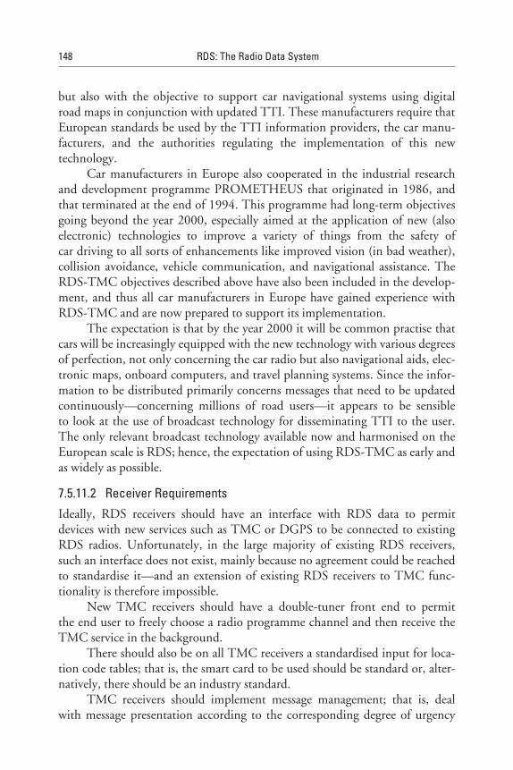
but also with the objective to support car navigational systems using digitalroad maps in conjunction with updated TTI. These manufacturers require thatEuropean standards be used by the TTI information providers, the car manu-facturers, and the authorities regulating the implementation of this newtechnology.
Car manufacturers in Europe also cooperated in the industrial researchand development programme PROMETHEUS that originated in 1986, andthat terminated at the end of 1994. This programme had long-term objectivesgoing beyond the year 2000, especially aimed at the application of new (alsoelectronic) technologies to improve a variety of things from the safety ofcar driving to all sorts of enhancements like improved vision (in bad weather),collision avoidance, vehicle communication, and navigational assistance. TheRDS-TMC objectives described above have also been included in the develop-ment, and thus all car manufacturers in Europe have gained experience withRDS-TMC and are now prepared to support its implementation.
The expectation is that by the year 2000 it will be common practise thatcars will be increasingly equipped with the new technology with various degreesof perfection, not only concerning the car radio but also navigational aids, elec-tronic maps, onboard computers, and travel planning systems. Since the infor-mation to be distributed primarily concerns messages that need to be updatedcontinuously—concerning millions of road users—it appears to be sensibleto look at the use of broadcast technology for disseminating TTI to the user.The only relevant broadcast technology available now and harmonised on theEuropean scale is RDS; hence, the expectation of using RDS-TMC as early andas widely as possible.
7.5.11.2 Receiver RequirementsIdeally, RDS receivers should have an interface with RDS data to permitdevices with new services such as TMC or DGPS to be connected to existingRDS radios. Unfortunately, in the large majority of existing RDS receivers,such an interface does not exist, mainly because no agreement could be reachedto standardise it—and an extension of existing RDS receivers to TMC func-tionality is therefore impossible.
New TMC receivers should have a double-tuner front end to permitthe end user to freely choose a radio programme channel and then receive theTMC service in the background.
There should also be on all TMC receivers a standardised input for loca-tion code tables; that is, the smart card to be used should be standard or, alter-natively, there should be an industry standard.
TMC receivers should implement message management; that is, dealwith message presentation according to the corresponding degree of urgency
148 RDS: The Radio Data System
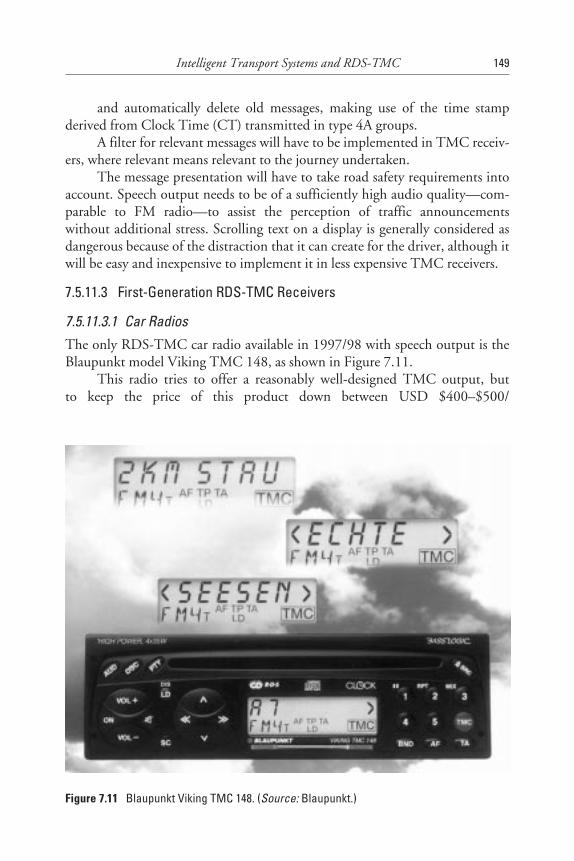
and automatically delete old messages, making use of the time stampderived from Clock Time (CT) transmitted in type 4A groups.
A filter for relevant messages will have to be implemented in TMC receiv-ers, where relevant means relevant to the journey undertaken.
The message presentation will have to take road safety requirements intoaccount. Speech output needs to be of a sufficiently high audio quality—com-parable to FM radio—to assist the perception of traffic announcementswithout additional stress. Scrolling text on a display is generally considered asdangerous because of the distraction that it can create for the driver, although itwill be easy and inexpensive to implement it in less expensive TMC receivers.
7.5.11.3 First-Generation RDS-TMC Receivers
7.5.11.3.1 Car RadiosThe only RDS-TMC car radio available in 1997/98 with speech output is theBlaupunkt model Viking TMC 148, as shown in Figure 7.11.
This radio tries to offer a reasonably well-designed TMC output, butto keep the price of this product down between USD $400–$500/
Intelligent Transport Systems and RDS-TMC 149
Figure 7.11 Blaupunkt Viking TMC 148. (Source: Blaupunkt.)
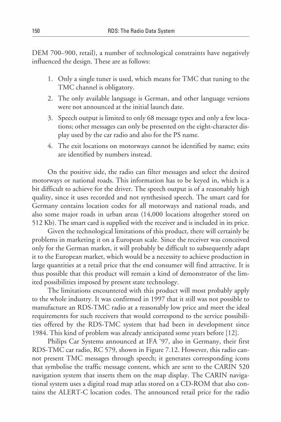
DEM 700–900, retail), a number of technological constraints have negativelyinfluenced the design. These are as follows:
1. Only a single tuner is used, which means for TMC that tuning to theTMC channel is obligatory.
2. The only available language is German, and other language versionswere not announced at the initial launch date.
3. Speech output is limited to only 68 message types and only a few loca-tions; other messages can only be presented on the eight-character dis-play used by the car radio and also for the PS name.
4. The exit locations on motorways cannot be identified by name; exitsare identified by numbers instead.
On the positive side, the radio can filter messages and select the desiredmotorways or national roads. This information has to be keyed in, which is abit difficult to achieve for the driver. The speech output is of a reasonably highquality, since it uses recorded and not synthesised speech. The smart card forGermany contains location codes for all motorways and national roads, andalso some major roads in urban areas (14,000 locations altogether stored on512 Kb). The smart card is supplied with the receiver and is included in its price.
Given the technological limitations of this product, there will certainly beproblems in marketing it on a European scale. Since the receiver was conceivedonly for the German market, it will probably be difficult to subsequently adaptit to the European market, which would be a necessity to achieve production inlarge quantities at a retail price that the end consumer will find attractive. It isthus possible that this product will remain a kind of demonstrator of the lim-ited possibilities imposed by present state technology.
The limitations encountered with this product will most probably applyto the whole industry. It was confirmed in 1997 that it still was not possible tomanufacture an RDS-TMC radio at a reasonably low price and meet the idealrequirements for such receivers that would correspond to the service possibili-ties offered by the RDS-TMC system that had been in development since1984. This kind of problem was already anticipated some years before [12].
Philips Car Systems announced at IFA ‘97, also in Germany, their firstRDS-TMC car radio, RC 579, shown in Figure 7.12. However, this radio can-not present TMC messages through speech; it generates corresponding iconsthat symbolise the traffic message content, which are sent to the CARIN 520navigation system that inserts them on the map display. The CARIN naviga-tional system uses a digital road map atlas stored on a CD-ROM that also con-tains the ALERT-C location codes. The announced retail price for the radio
150 RDS: The Radio Data System
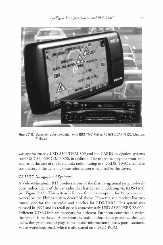
was approximately USD $500/DEM 800 and the CARIN navigation systemscosts USD $3,000/DEM 4,800, in addition. The tuner has only one front-end,and, as in the case of the Blaupunkt radio, tuning to the RDS- TMC channel iscompulsory if the dynamic route information is required by the driver.
7.5.11.3.2 Navigational SystemsA Volvo/Mitsubishi RTI product is one of the first navigational systems devel-oped independent of the car radio that has dynamic updating via RDS-TMC(see Figure 7.13). This system is factory fitted as an option for Volvo cars andworks like the Philips system described above. However, the receiver has twotuners, one for the car radio and another for RDS-TMC. This system wasreleased in 1997 and its retail price is approximately USD $3,600/SEK 28,000.Different CD-ROMs are necessary for different European countries in whichthe system is marketed. Apart from the traffic information presented throughicons, the system also displays some tourist information (hotels, petrol stations,Volvo workshops, etc.), which is also stored on the CD-ROM.
Intelligent Transport Systems and RDS-TMC 151
Figure 7.12 Dynamic route navigation with RDS-TMC Philips RC 579 + CARIN 520. (Source:Philips.)
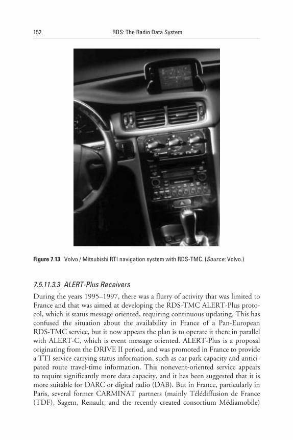
7.5.11.3.3 ALERT-Plus ReceiversDuring the years 1995–1997, there was a flurry of activity that was limited toFrance and that was aimed at developing the RDS-TMC ALERT-Plus proto-col, which is status message oriented, requiring continuous updating. This hasconfused the situation about the availability in France of a Pan-EuropeanRDS-TMC service, but it now appears the plan is to operate it there in parallelwith ALERT-C, which is event message oriented. ALERT-Plus is a proposaloriginating from the DRIVE II period, and was promoted in France to providea TTI service carrying status information, such as car park capacity and antici-pated route travel-time information. This nonevent-oriented service appearsto require significantly more data capacity, and it has been suggested that it ismore suitable for DARC or digital radio (DAB). But in France, particularly inParis, several former CARMINAT partners (mainly Télédiffusion de France(TDF), Sagem, Renault, and the recently created consortium Médiamobile)
152 RDS: The Radio Data System
Figure 7.13 Volvo / Mitsubishi RTI navigation system with RDS-TMC. (Source: Volvo.)
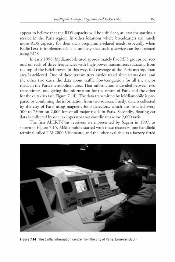
appear to believe that the RDS capacity will be sufficient, at least for starting aservice in the Paris region. In other locations where broadcasters use muchmore RDS capacity for their own programme-related needs, especially whenRadioText is implemented, it is unlikely that such a service can be operatedusing RDS.
In early 1998, Médiamobile used approximately five RDS groups per sec-ond on each of three frequencies with high-power transmitters radiating fromthe top of the Eiffel tower. In this way, full coverage of the Paris metropolitanarea is achieved. One of these transmitters carries travel time status data, andthe other two carry the data about traffic flow/congestion for all the majorroads in the Paris metropolitan area. That information is divided between twotransmitters, one giving the information for the centre of Paris and the otherfor the outskirts (see Figure 7.14). The data transmitted by Médiamobile is pre-pared by combining the information from two sources. Firstly, data is collectedby the city of Paris using magnetic loop detectors, which are installed every500 to 750m on 2,000 km of all major roads in Paris. Secondly, floating cardata is collected by one taxi operator that coordinates some 2,000 taxis.
The first ALERT-Plus receivers were presented by Sagem in 1997, asshown in Figure 7.15. Médiamobile started with these receivers: one handheldterminal called TM 2000 Visionaute, and the other available as a factory-fitted
Intelligent Transport Systems and RDS-TMC 153
Figure 7.14 The traffic information centre from the city of Paris. (Source: EBU.)
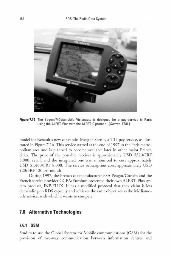
model for Renault’s new car model Megane Scenic, a TTI pay service, as illus-trated in Figure 7.16. This service started at the end of 1997 in the Paris metro-politan area and is planned to become available later in other major Frenchcities. The price of the portable receiver is approximately USD $520/FRF3,000, retail, and the integrated one was announced to cost approximatelyUSD $1,400/FRF 8,000. The service subscription costs approximately USD$20/FRF 120 per month.
During 1997, the French car manufacturer PSA Peugot/Citroën and theFrench service provider CGEA/Eurolum presented their own ALERT-Plus sys-tem product, INF-FLUX. It has a modified protocol that they claim is lessdemanding on RDS capacity and achieves the same objectives as the Médiamo-bile service, with which it wants to compete.
7.6 Alternative Technologies
7.6.1 GSM
Studies to use the Global System for Mobile communications (GSM) for theprovision of two-way communication between information centres and
154 RDS: The Radio Data System
Figure 7.15 The Sagem/Médiamobile Visionaute is designed for a pay-service in Parisusing the ALERT-Plus with the ALERT-C protocol. (Source: EBU.)
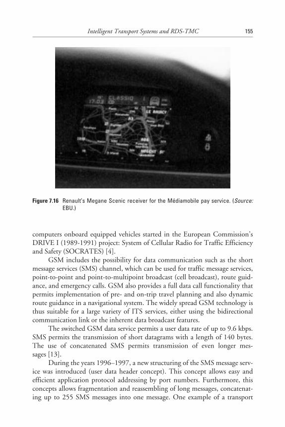
computers onboard equipped vehicles started in the European Commission’sDRIVE I (1989-1991) project: System of Cellular Radio for Traffic Efficiencyand Safety (SOCRATES) [4].
GSM includes the possibility for data communication such as the shortmessage services (SMS) channel, which can be used for traffic message services,point-to-point and point-to-multipoint broadcast (cell broadcast), route guid-ance, and emergency calls. GSM also provides a full data call functionality thatpermits implementation of pre- and on-trip travel planning and also dynamicroute guidance in a navigational system. The widely spread GSM technology isthus suitable for a large variety of ITS services, either using the bidirectionalcommunication link or the inherent data broadcast features.
The switched GSM data service permits a user data rate of up to 9.6 kbps.SMS permits the transmission of short datagrams with a length of 140 bytes.The use of concatenated SMS permits transmission of even longer mes-sages [13].
During the years 1996–1997, a new structuring of the SMS message serv-ice was introduced (user data header concept). This concept allows easy andefficient application protocol addressing by port numbers. Furthermore, thisconcepts allows fragmentation and reassembling of long messages, concatenat-ing up to 255 SMS messages into one message. One example of a transport
Intelligent Transport Systems and RDS-TMC 155
Figure 7.16 Renault’s Megane Scenic receiver for the Médiamobile pay service. (Source:EBU.)
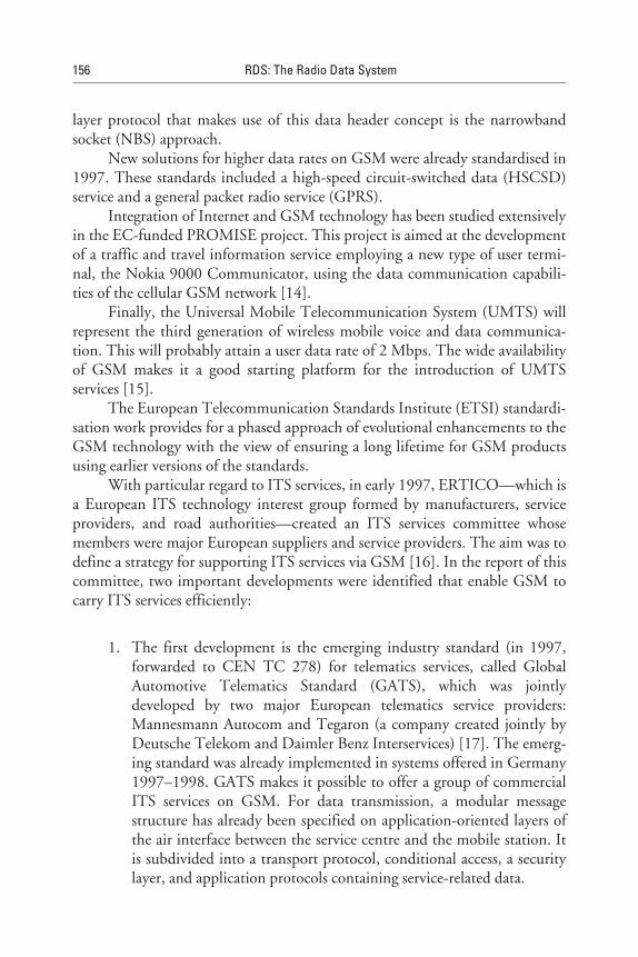
layer protocol that makes use of this data header concept is the narrowbandsocket (NBS) approach.
New solutions for higher data rates on GSM were already standardised in1997. These standards included a high-speed circuit-switched data (HSCSD)service and a general packet radio service (GPRS).
Integration of Internet and GSM technology has been studied extensivelyin the EC-funded PROMISE project. This project is aimed at the developmentof a traffic and travel information service employing a new type of user termi-nal, the Nokia 9000 Communicator, using the data communication capabili-ties of the cellular GSM network [14].
Finally, the Universal Mobile Telecommunication System (UMTS) willrepresent the third generation of wireless mobile voice and data communica-tion. This will probably attain a user data rate of 2 Mbps. The wide availabilityof GSM makes it a good starting platform for the introduction of UMTSservices [15].
The European Telecommunication Standards Institute (ETSI) standardi-sation work provides for a phased approach of evolutional enhancements to theGSM technology with the view of ensuring a long lifetime for GSM productsusing earlier versions of the standards.
With particular regard to ITS services, in early 1997, ERTICO—which isa European ITS technology interest group formed by manufacturers, serviceproviders, and road authorities—created an ITS services committee whosemembers were major European suppliers and service providers. The aim was todefine a strategy for supporting ITS services via GSM [16]. In the report of thiscommittee, two important developments were identified that enable GSM tocarry ITS services efficiently:
1. The first development is the emerging industry standard (in 1997,forwarded to CEN TC 278) for telematics services, called GlobalAutomotive Telematics Standard (GATS), which was jointlydeveloped by two major European telematics service providers:Mannesmann Autocom and Tegaron (a company created jointly byDeutsche Telekom and Daimler Benz Interservices) [17]. The emerg-ing standard was already implemented in systems offered in Germany1997–1998. GATS makes it possible to offer a group of commercialITS services on GSM. For data transmission, a modular messagestructure has already been specified on application-oriented layers ofthe air interface between the service centre and the mobile station. Itis subdivided into a transport protocol, conditional access, a securitylayer, and application protocols containing service-related data.
156 RDS: The Radio Data System
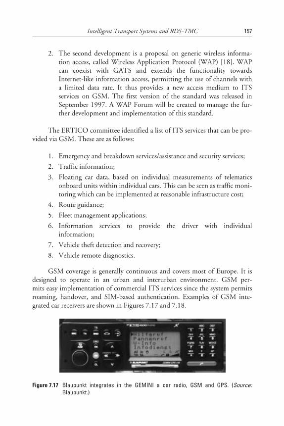
2. The second development is a proposal on generic wireless informa-tion access, called Wireless Application Protocol (WAP) [18]. WAPcan coexist with GATS and extends the functionality towardsInternet-like information access, permitting the use of channels witha limited data rate. It thus provides a new access medium to ITSservices on GSM. The first version of the standard was released inSeptember 1997. A WAP Forum will be created to manage the fur-ther development and implementation of this standard.
The ERTICO committee identified a list of ITS services that can be pro-vided via GSM. These are as follows:
1. Emergency and breakdown services/assistance and security services;
2. Traffic information;
3. Floating car data, based on individual measurements of telematicsonboard units within individual cars. This can be seen as traffic moni-toring which can be implemented at reasonable infrastructure cost;
4. Route guidance;
5. Fleet management applications;
6. Information services to provide the driver with individualinformation;
7. Vehicle theft detection and recovery;
8. Vehicle remote diagnostics.
GSM coverage is generally continuous and covers most of Europe. It isdesigned to operate in an urban and interurban environment. GSM per-mits easy implementation of commercial ITS services since the system permitsroaming, handover, and SIM-based authentication. Examples of GSM inte-grated car receivers are shown in Figures 7.17 and 7.18.
Intelligent Transport Systems and RDS-TMC 157
Figure 7.17 Blaupunkt integrates in the GEMINI a car radio, GSM and GPS. (Source:Blaupunkt.)
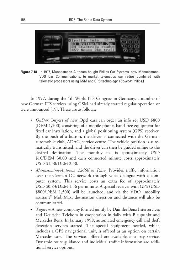
In 1997, during the 4th World ITS Congress in Germany, a number ofnew German ITS services using GSM had already started regular operation orwere announced [19]. These are as follows:
• OnStar: Buyers of new Opel cars can order an info set USD $800(DEM 1,500) consisting of a mobile phone, hand-free equipment forfixed car installation, and a global positioning system (GPS) receiver.By the push of a button, the driver is connected with the Germanautomobile club, ADAC, service centre. The vehicle position is auto-matically transmitted, and the driver can then be guided online to thedesired destination. The monthly fee is approximately USD$16/DEM 30.00 and each connected minute costs approximatelyUSD $1.30/DEM 2.50.
• Mannesmann-Autocom 22666 or Passo: Provides traffic informationover the German D2 network through voice dialogue with a com-puter system. This service costs an extra fee of approximatelyUSD $0.83/DEM 1.56 per minute. A special receiver with GPS (USD$800/DEM 1,500) will be launched, and via the VDO “mobilityassistant” MobiMax, destination direction and distance will also becommunicated.
• Tegaron: A new company formed jointly by Daimler Benz Interservicesand Deutsche Telekom in cooperation initially with Blaupunkt andMercedes Benz. In January 1998, automated emergency call and theftdetection services started. The special equipment needed, whichincludes a GPS navigational unit, is offered as an option on certainMercedes cars. The services offered are available as a pay service.Dynamic route guidance and individual traffic information are addi-tional service options.
158 RDS: The Radio Data System
Figure 7.18 In 1997, Mannesmann-Autocom bought Philips Car Systems, now Mannesmann-VDO Car Communications, to market telematics car radios combined withtelematic processors using GSM and GPS technology. (Source: Philips.)
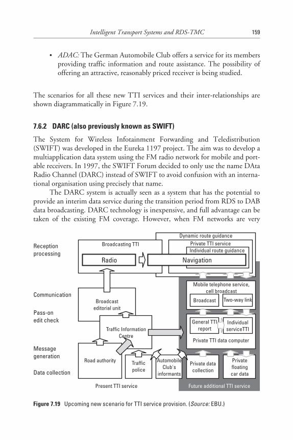
• ADAC: The German Automobile Club offers a service for its membersproviding traffic information and route assistance. The possibility ofoffering an attractive, reasonably priced receiver is being studied.
The scenarios for all these new TTI services and their inter-relationships areshown diagrammatically in Figure 7.19.
7.6.2 DARC (also previously known as SWIFT)
The System for Wireless Infotainment Forwarding and Teledistribution(SWIFT) was developed in the Eureka 1197 project. The aim was to develop amultiapplication data system using the FM radio network for mobile and port-able receivers. In 1997, the SWIFT Forum decided to only use the name DAtaRadio Channel (DARC) instead of SWIFT to avoid confusion with an interna-tional organisation using precisely that name.
The DARC system is actually seen as a system that has the potential toprovide an interim data service during the transition period from RDS to DABdata broadcasting. DARC technology is inexpensive, and full advantage can betaken of the existing FM coverage. However, when FM networks are very
Intelligent Transport Systems and RDS-TMC 159
Receptionprocessing
Communication
Pass-onedit check
Messagegeneration
Data collection
Broadcasting TTI
Broadcasteditorial unit
Private TTI serviceDynamic route guidance
Individual route guidance
Radio Navigation
Traffic InformationCentre
Road authority Trafficpolice
AutomobileClub's
informants
Privatefloatingcar data
Private datacollection
Private TTI data computer
General TTIreport
IndividualserviceTTI
Mobile telephone service,cell broadcast
Broadcast Two-way link
Present TTI service Future additional TTI service
Figure 7.19 Upcoming new scenario for TTI service provision. (Source: EBU.)
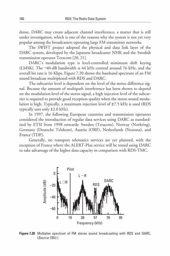
dense, DARC may create adjacent channel interference, a matter that is stillunder investigation, which is one of the reasons why the system is not yet verypopular among the broadcasters operating large FM transmitter networks.
The SWIFT project adopted the physical and data link layer of theDARC system, developed by the Japanese broadcaster NHK and the Swedishtransmission operator Teracom [20, 21].
DARC’s modulation type is level-controlled minimum shift keying(LMSK). The −40-dB bandwidth is 44 kHz centred around 76 kHz, and theoverall bit rate is 16 Kbps. Figure 7.20 shows the baseband spectrum of an FMsound broadcast multiplexed with RDS and DARC.
The subcarrier level is dependent on the level of the stereo difference sig-nal. Because the amount of multipath interference has been shown to dependon the modulation level of the stereo signal, a high injection level of the subcar-rier is required to provide good reception quality when the stereo sound modu-lation is high. Typically, a maximum injection level of ±7.5 kHz is used (RDStypically uses only ±2.0 kHz).
In 1997, the following European countries and transmission operatorsconsidered the introduction of regular data services using DARC as standard-ised by ETSI from 1998 onwards: Sweden (Teracom), Norway (Norkring),Germany (Deutsche Telekom), Austria (ORF), Netherlands (Nozema), andFrance (TDF).
Generally, no transport telematics services are yet planned, with theexception of France where the ALERT-Plus service will be tested using DARCto take advantage of the higher data capacity in comparison with RDS-TMC.
160 RDS: The Radio Data System
L R+
L R−
Pilot
RDSDARC
Ampl
itude
(dB)
−20
0
−40
−60
19 38 57 760 95Frequency (kHz)
Figure 7.20 Multiplex spectrum of FM stereo sound broadcasting with RDS and DARC.(Source: EBU.)
In Japan, the DARC system is used in conjunction with radio and infra-red beacons for the operation of the Vehicle Information and CommunicationSystem (VICS) service, which has provided traffic information to in-vehicleunits since 1996 in three large metropolitan areas (Tokyo, Aichi, and Osaka)[22, 23].
Three different service levels are in operation:
• Level 3: Colour map display giving traffic density information;
• Level 2: Simple graphic display depicting traffic information;
• Level 1: Text information essentially giving travel time.
The system is very widely supported by some 27 consumer electronicsmanufacturers, offering 74 types of onboard VICS products in 1997. In 1996,many of the navigational systems sold in Japan (800,000 units) could use VICSfor dynamic updating. There are no plans yet in Europe to use VICS, sinceRDS-TMC will give similar functionality.
7.6.3 DAB Delivery of TMC Messages
While Sweden expects to cease FM radio broadcasts in favour of digital broad-casting within 10 years, few other countries expect to make the change thatquickly, even though most European countries are now launching digital radioservices (as are Canada, Australia, and South America).
Digital audio broadcasting (DAB) promises broadcast audio quality closeto that of compact disc and includes several data stream options that can beused for additional data services such as TMC. The message capacity of DAB ispotentially as much as 1,000 times greater than RDS-TMC. Although the stan-dards for DAB have been adequately developed for audio broadcasting, theyhave not yet been fully developed for additional data. In 1997, various field tri-als were undertaken to evaluate the use of road maps delivered by DAB usingthe multi-media object-transfer (MOT) protocol for presentation on LCDdisplays.
DAB-TMC, in particular, needs more work, and the European Broad-casting Union is coordinating that work in the B/TPEG project, which issupported by a wide range of consumer electronics manufacturers, navigationsystems companies, and service providers.
It is interesting to note that the European Broadcasting Union StatementD81-1996 recommends that broadcasters should develop their infrastructuresfor RDS-TMC with the expectation that the infrastructure can be used forDAB later. Thus, it will be important to develop systems especially for TTI
Intelligent Transport Systems and RDS-TMC 161
message generation that provide output to one or more transmission deliverypossibilities and to include a smooth path for migration to DAB.
In 1997, 100 million people in Europe could already receive pilot DABtransmissions if they had the appropriate DAB receivers—but the receivers areso expensive that the market has not generally accepted them, although theyhave been available for a number of years. Nevertheless, the development ofDAB transmission networks will take a significant amount of time to achievecoverage that matches that of FM radio. For example, in the United Kingdom,the BBC plans to invest GBP 10 million/USD $16 million to achieve coveragefor 60% of the population by the end of 1998. It could easily take another fiveyears or more to reach 95% coverage, and even that is not as good as the presentFM coverage.
7.7 The Longer Term Future of TMC
RDS-TMC was given a huge boost in 1997 when the European Union (EU)raised the issue of implementation of services to a high political level, givingvery strong support to those involved in the final development phase ofRDS-TMC. The first services were being announced in the same year, and inGermany, services were beginning to reach completion and were ready for con-sumer use. While it is difficult to predict how long TMC will be delivered byRDS, it can be assumed that this high-level EU concern will result in wide-spread adoption of the technology, and thus it can be expected that RDS-TMCwill be available for many years to come. The possible development of TTIservices delivery is shown in Figure 7.21.
However, the increased availability of the TTI data gathered for thesenew TMC services suggests that there will be a surfeit of messages, especially inthe metropolitan areas, which RDS-TMC will not be able to handle due to thelimited bandwidth available in RDS. Furthermore, there is now the possibilityof using many different delivery mechanisms, such as DAB, DARC (alsoknown as SWIFT), digital video broadcasting (DVB), GSM, Internet, and tele-text in analogue TV. This new delivery environment expansion was recognisedby the EBU in Statement D81-1996 [24], which recommends that broadcast-ers should develop their infrastructures for both RDS and DAB. But the EBUis taking an even more progressive step, having authorised a new develop-ment project known as B/TPEG, which is briefed to develop the TransportProgramme Experts Group (TPEG) Protocol [25, 26]. In the short to mediumterm, the public broadcasters of the EBU support the B/TPEG activity toachieve a suitable protocol for DAB, and expect many other useful proposalsto come from the B/TPEG project.
162 RDS: The Radio Data System
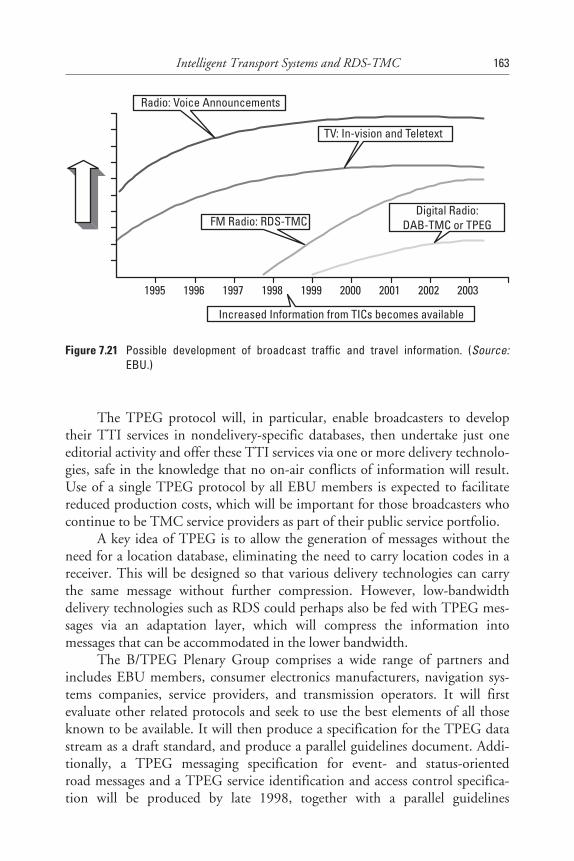
The TPEG protocol will, in particular, enable broadcasters to developtheir TTI services in nondelivery-specific databases, then undertake just oneeditorial activity and offer these TTI services via one or more delivery technolo-gies, safe in the knowledge that no on-air conflicts of information will result.Use of a single TPEG protocol by all EBU members is expected to facilitatereduced production costs, which will be important for those broadcasters whocontinue to be TMC service providers as part of their public service portfolio.
A key idea of TPEG is to allow the generation of messages without theneed for a location database, eliminating the need to carry location codes in areceiver. This will be designed so that various delivery technologies can carrythe same message without further compression. However, low-bandwidthdelivery technologies such as RDS could perhaps also be fed with TPEG mes-sages via an adaptation layer, which will compress the information intomessages that can be accommodated in the lower bandwidth.
The B/TPEG Plenary Group comprises a wide range of partners andincludes EBU members, consumer electronics manufacturers, navigation sys-tems companies, service providers, and transmission operators. It will firstevaluate other related protocols and seek to use the best elements of all thoseknown to be available. It will then produce a specification for the TPEG datastream as a draft standard, and produce a parallel guidelines document. Addi-tionally, a TPEG messaging specification for event- and status-orientedroad messages and a TPEG service identification and access control specifica-tion will be produced by late 1998, together with a parallel guidelines
Intelligent Transport Systems and RDS-TMC 163
Radio: Voice Announcements
TV: In-vision and Teletext
FM Radio: RDS-TMCDigital Radio:
DAB-TMC or TPEG
Increased Information from TICs becomes available
1995 1996 1997 1998 1999 2000 2001 2002 2003
Figure 7.21 Possible development of broadcast traffic and travel information. (Source:EBU.)
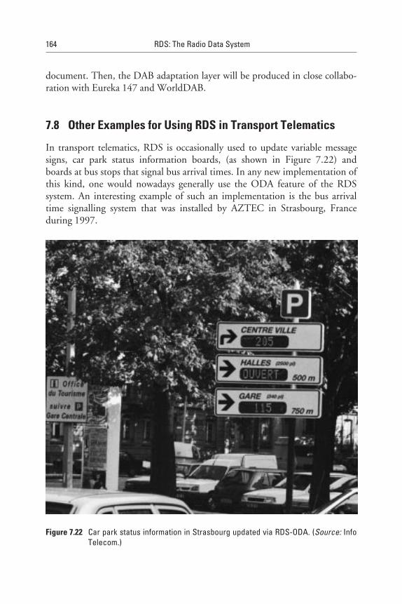
document. Then, the DAB adaptation layer will be produced in close collabo-ration with Eureka 147 and WorldDAB.
7.8 Other Examples for Using RDS in Transport Telematics
In transport telematics, RDS is occasionally used to update variable messagesigns, car park status information boards, (as shown in Figure 7.22) andboards at bus stops that signal bus arrival times. In any new implementation ofthis kind, one would nowadays generally use the ODA feature of the RDSsystem. An interesting example of such an implementation is the bus arrivaltime signalling system that was installed by AZTEC in Strasbourg, Franceduring 1997.
164 RDS: The Radio Data System
Figure 7.22 Car park status information in Strasbourg updated via RDS-ODA. (Source: InfoTelecom.)

7.9 Conclusions
As has been shown, RDS-TMC has a number of unresolved problems thatexplain to a certain degree the difficulties encountered in its general introduc-tion. As it is generally known, each technology has an optimal time windowwhere it can succeed; and after some time, other and better performing tech-nologies will take over. When these appear on the horizon, it is false to con-clude that the knowledge about the better technology is already the end of theso far believed good solution.
In consumer electronics, it takes years for the market to succeed with anew technology. Although receiver prices and profit margins for the industryare relatively low, competition and quality of the products is usually high andthe lifetime of the equipment is long.
Success is only possible when well-coordinated standards exist, the tech-nology to be used is mature, there is full consensus of all parties involved inservice provision, and the whole industry is ready to go into mass production.In addition, there must be a high demand by the end users for a product that isattractive, safe for the driver, and really useful on the road. As we have seen,RDS-TMC remains surrounded by many open questions. Final answers aboutsuccess or failure are not yet possible. The infrastructures required and builtto collect traffic and traveller information with the view of RDS-TMC serviceprovision will be needed anyway, regardless of the advent of new alternativetechnologies. Without any doubt, they represent useful long-term investmentsthat are absolutely necessary for high-quality service provision over large areassuch as the European Union or the United States.
For RDS-TMC to succeed, we need stable and widely agreed upon stan-dards for the consumer electronics industry. The way their development hasbeen coordinated by the European Commission has not, unfortunately, yet ledto the success expected. What lesson can now be learned from 15 years of devel-opment effort put into this technological concept? One thing is certain: Thosewho have participated in this experience can now contribute to the develop-ment of better solutions that will use technologies such as DAB, DARC,and GSM.
References
[1] European Commission, Community Strategy and Framework for the Deployment ofRoad Transport Telematics in Europe and Proposals for Initial Action, Brussels, 20.05.97COM(97) 223 final.
Intelligent Transport Systems and RDS-TMC 165
[2] Resolution on Standards for Traffic Messages broadcast using the Radio Data SystemTraffic Message Channel, The Council of Ministers of ECMT, Antalya, May 22-23,1991.
[3] Council Resolution of the Sept. 28, 1995 European Commission, Official Journal95/C 264.
[4] Catling, I., Advanced Technology for Road Transport: IVHS and ATT, Norwood, MA:Artech House, 1994.
[5] Bücken, R., “Verkehrsfunk auf Abruf,” Funkschau No. 20, 1997, pp. 70–73.
[6] VDA: Tatsachen und Zahlen aus der Kraftverkehswirtschaft-59. Folge, Frankfurt/M.,1995.
[7] ERTICO, TELTEN Final Report Vol. 1, European Commission DG VII, Brussels, 1994.
[8] Ungerer, D., July 1997, not yet published.
[9] European Conference of Ministers of Transport (ECMT) document, New Informationtechnologies in the Road Transport Sector-Policy Issues, Ergonomics and Safety.
[10] British Standards Institute, DD 235: Draft for Development-Guide to In-vehicle Infor-mation Systems, 1996.
[11] Agreement on Guidelines for the Design and Installation of Information and Communi-cations Systems in Motor Vehicles, German Economic Forum on Telematics inTransport, Nov. 1996.
[12] Kopitz, D., “Development of the Traffic Message Channel in RDS,” EBU TechnicalReview, No. 245, Feb. 1991, pp. 29–32.
[13] Redl, S. M., M. K. Weber, and M. W. Oliphant, An Introduction to GSM, Norwood, MA:Artech House, 1995.
[14] Geen. P., “Standardisation of Traveller and Traffic Information via Cellular Networks,”4th Word Congress on Intelligent Transport Systems, Berlin Germany, Oct. 1997.
[15] Decker, P., A. Salomäki, and S. Turunen, “GSM and UMTS as a Platform for TransportTelematics Applications,” 4th Word Congress on Intelligent Transport Systems, Berlin,Germany, Oct. 1997.
[16] GSM based ITS Services-ERTICO Strategy for Implementation, V. 1.4, ERTICO,Rue de la Régence 61, B-1000 Brussels, Belgium, Nov. 1997.
[17] Vieweg, S., GATS, “Global Automotive Telematics Standard and Example of Implemen-tation,” 4th Word Congress on Intelligent Transport Systems, Berlin, Germany, Oct. 1997.
[18] Lang, K. E., “Wireless Application Protocol,” 4th Word Congress on Intelligent TransportSystems, Berlin, Germany, Oct. 1997.
[19] “Online Motoring,” Translated reprint from ADAC Motorwelt 04/97, 4th Word Congresson Intelligent Transport Systems, Berlin, Germany, Oct. 1997.
166 RDS: The Radio Data System
[20] Scomazzon, P. and R. Andersson, “A high bit-rate data broadcasting system using the ter-restrial FM radio network / SWIFT Eureka 1197 project,” EBU Technical Review,No. 264, Summer 1995, pp. 4–12
[21] Kuroda, T., M. Takada, and O. Yamada, “Development of an FM multiplex broadcastingsystem having a large transmission capacity,” IBC, Brighton, 1990, pp. 241–245.
[22] Isobe, T., et al., “Traffic Information Services using FM multiplex broadcasting,” IVHSWorkshop on Communication with Vehicles, July 1992.
[23] Kojima, H., T. Yamamoto, and Y. Kumagai, “VICS Information Broadcasting Service /FM Multiplex Broadcasting,” 4th Word Congress on Intelligent Transport Systems, Berlin,Germany, Oct. 1997.
[24] EBU Statement D81-1996: RDS-TMC (Traffic Message Channel), EBU TechnicalReview, No. 270, Winter 199), p. 45.
[25] Parnall, S. J., “The longer term future of TMC,” Proceedings of the TMC-Now! Conference,European Broadcasting Union, CP 67, CH-1218 Grand Saconnex (GE), Switzerland,March 1997.
[26] Parnall, S. J., “TPEG” - A strawman proposal for a stream format protocol for transportinformation, BBC Research and Development Department, R&D Technical Note 0747(97)P, March 11, 1997.
[27] ADAC-The Active Partner of Road Transport Telematics, 4th Word Congress on IntelligentTransport Systems, Berlin, Germany, Oct. 1997. Also published in German in ADACMotorwelt, Dec. 1997, p. 46.
Intelligent Transport Systems and RDS-TMC 167
8Basic and Enhanced Radio Paging
8.1 Introduction
This chapter introduces the concept of FM Radio Paging. This technique offersthe fastest way to provide a full paging communication coverage for a metro-politan area or even complete region or country. FM paging is growing quicklybecause it is cost-effective and it mostly uses an infrastructure already built forother communication purposes. FM Radio Paging puts the existing telephonesystem and FM broadcasting stations to more profitable use, providing a valu-able service and generating revenue for the operator.
In addition to the paging system described in earlier versions of theRDS/RBDS standards referred to as “basic paging,” the 1998 version ofthe new RDS/RBDS standards introduces the “enhanced paging” protocolwhile keeping full compatibility with the earlier one.
The aim of the enhanced paging protocol is to upgrade the battery life-time of a pager, as well as to easily permit regional and international paging,and multioperator and multiservices operation.
8.2 What can be Achieved With Radio Paging?
The Radio Paging (RP) feature is intended to permit multiplexing of the pag-ing signals (type 1A groups, 4A groups, 7A groups, and 13A groups—used onlyfor the enhanced paging mode) into the (RDS) data stream containing any ofthe other RDS features. This technique permits the provision of Radio Pagingusing existing VHF/FM broadcasts as a transport facility, thereby avoiding the
169
need for a dedicated network of transmitters and at the same time making useof the relatively large service areas of FM transmitters.
RDS Radio Paging has the great advantage that an existing VHF/FMbroadcast network can be used to carry this service. This is especially true indeveloping countries, where it is difficult to implement a special radio transmit-ter network to only carry a paging service, as would be required for a POCSAGpaging system. From an economics point of view, this is usually the most cost-effective solution for implementing a Radio Paging service, and for a broad-caster or transmission operator, there is also the opportunity to earn revenuefrom using RDS to provide such a service. The capacity of an RDS Radio Pag-ing service is approximately 40,000 subscribers per broadcast network of trans-mitters. The capacity is strongly influenced by the mix of paging services that isprovided to users. If the paging service carries only a bleep tone to alert thesubscriber, the capacity will be higher; but if long alphanumeric messages arecarried, then the capacity will, of course, be much lower since these requiremore paging data groups to carry the information.
Some of the countries already making extensive use of the RDS RadioPaging technique are France [1], Germany, Sweden, Bulgaria, Hungary, Slove-nia, Croatia, the Czech and Slovak Republics, Ireland, Spain, Dubai, India,China, Indonesia, Russia, Ukraine, Tanzania, South Africa, Mexico, and theUnited States.
The full specification for the implementation of RDS Radio Paging isgiven in Annex M of the new RDS/RBDS specifications [2,3].
In comparison to former RDS/RBDS standards, significant enhance-ments were included, as follows:
1. A set of variable-length message types for numeric and function mes-sages has been added to the RDS paging definition, enabling moreflexible and efficient use of the transmission.
2. The new definition includes message types for both national andinternational paging. Previously, only fixed-length messages weredefined for numeric paging.
3. A repetition flag has been added. This enables more intelligent proc-essing of the received messages when messages are repeated toimprove the reception reliability.
4. A paging call counter has been added. This is a running number foreach individual message sent to a subscriber. This number permits theuser to be alerted when a message could not be received.
5. The type 13A group concept was introduced for the enhanced pagingmode.
170 RDS: The Radio Data System
6. A global addressing scheme was added for country, operator, andoperator’s service area management purposes, which permits severaloperators (15 operators per country; that is, operator codes (OPC),with 63 different service areas per country, which are paging areacodes (PAC) to provide Radio Paging services for the same servicearea without any conflict among them). These codes are carried intype 1A groups, variants 0 and 2.
7. Roaming (international links) for international paging is also possible.
8. A paging network can now be defined without any connection to thePI code, as was previously the case. Only the country code compo-nent of the PI code is being used.
9. It is possible to design and manage a paging network completelyunrelated to the radio programmes that the transmissions carry.
10. A new battery-saving mode has been defined that improves signifi-cantly (10 to 15 times) the power consumption of paging receivers(i.e., the pager is only fully powered during 0.3 seconds out of a two-minute cycle). This is achieved thanks to type 13A groups beingplaced at the beginning of the six-second interval, already definedin the basic paging mode. Battery life can be as high as up to2,000 hours.
11. The address range of receivers was enhanced from one million to tenmillion subscriber address codes.
The enhancements described permit an easy upgrade of existingnetworks.
Radio Paging is intended to provide a broadcast paging service makinguse of the type 7A group for transporting the paging messages (see Figure 8.1),associated with the use of type 1A, 4A, and 13A groups (enhanced paging modeonly). Subscribers to a paging service will require a special pocket pagingreceiver in which the subscriber address code is stored. Five types of call mes-sages are possible:
1. A simple call (bleep tone) without additional message;
2. A 10- or 15-digit (international), or 18-digit numeric message;
3. An alphanumeric message of 80 characters, maximum;
4. Variable-length message;
5. Functions message.
Basic and Enhanced Radio Paging 171
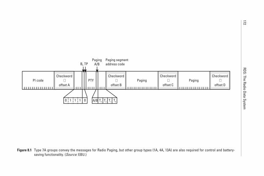
172RDS:The
RadioData
System
PI code PTY Paging Paging
PagingA/B
Paging segmentaddress code
A/B T3 T2 T1 T0
Checkword+
offset A
Checkword+
offset B
Checkword+
offset C
Checkword+
offset D
B0 TP
0 1 011
Figure 8.1 Type 7A groups convey the messages for Radio Paging, but other group types (1A, 4A, 13A) are also required for control and battery-saving functionality. (Source: EBU.)

In Figure 8.1, block 1 comprises the PI code found as the first block ofevery RDS group type. Blocks 3 and 4 are used to carry the paging messageinformation. In block 2, the last five bits are used to control the paging infor-mation. Bit A/B is used as a flag that changes its value between different pagingcalls, thus indicating the start of a new or repeated call. Bits T3–T0 are used as afour-bit paging segment address code and to indicate the type of an additionalmessage that follows.
8.3 RDS Paging Operational Infrastructure
The RDS paging network needs to bring together a paging service centre withthe existing broadcast network to allow the paging data to reach the airwaves.Various configurations are possible, and Figure 8.2 shows many of the commu-nication link options.
The public switched telephone network (PSTN) is used to relay requestcalls to the paging control terminal (PCT) and to send the required acknow-ledgements between the caller and the PCT. This requires the installation of a
Basic and Enhanced Radio Paging 173
Paging controlterminal equipment
Network distributionequipment
Transmitter siteequipment
Administrative videodisplay terminal(s)
Printer(s)Operator
stationfor entryof pages
Digital oranalogue
telephonelines from
CentralOffice
Call billingcomputer system
Pagingcontrol
computer
SimplexTNPP
Port
RS232
RS232
Modem2-wire
Leasedlines toothersites
Databridge
(Optional equipment)
Modem RDSencoder To FM
transmitter
Figure 8.2 General description of an RDS paging system. (Source: EBU/RPA.)
special exchange designed for use in paging operations, performing thebasic functions of organisation, control, and billing. These exchanges arecommercially available from several manufacturers and can be located almostanywhere.
The paging message is processed with the addition of routing codes andother system management codes and then is packaged into an appropriate pro-tocol to be carried via a suitable high-quality data transmission network to theinput point or points of the FM broadcast network [6].
Mainly, two protocols are used. Originally the Telocator Network PagingProtocol (TNPP) was developed for wide area networks serving single-frequency systems, and it has also been used in RDS networks. The EuropeanBroadcasting Union (EBU) developed the Universal Encoder CommunicationProtocol (UECP), which in its latest version, 5.1, (see also Chapter 11),contains all the necessary commands for dynamically controlling RDS data tobe broadcast. It also “transports” paging messages for the operation of boththe basic paging mode and the enhanced paging protocol from the newRDS/RBDS standards [2–4].
It is important for the broadcaster or FM transmitter network operator toensure system reliability, and this is best served by amalgamating all data into asingle stream between studio centre and transmitter. These protocols will allowthe use of satellite links, microwave data links, and data circuits by telephonecables equipped with modems for data transmission, or any combination ofthese.
The input to the FM network may be connected at the broadcast studiocentre or at one, several, or all FM transmitting stations. If the input is to onetransmitting station, all others will receive the transmitted signal, includingthe subcarrier from the original transmitter. It will also be possible to rebroad-cast the transmitted multiplex (audio and data subcarrier) from the originaltransmitter by modulating it onto another VHF frequency. However, generallyspeaking, an RDS encoder may be required at each transmitter site to modulatethe data onto the subcarrier when only the baseband audio signal is rebroad-casted. In each FM transmitting station, the required configuration may bevery similar.
When operating RDS paging, it is necessary to provide an even more rug-ged data signal than the one required for mobile reception with a car radio.This is achieved by increasing the subcarrier deviation for RDS from the nor-mal value of ±2 kHz to a level of at least ±4 kHz, the reason being the verysmall antenna used in a pager. In addition to this, each paging message has tobe repeated two or even three times at a sufficiently spaced time interval ofseveral minutes, assuming that most pagers will be used by people that are onthe move.
174 RDS: The Radio Data System
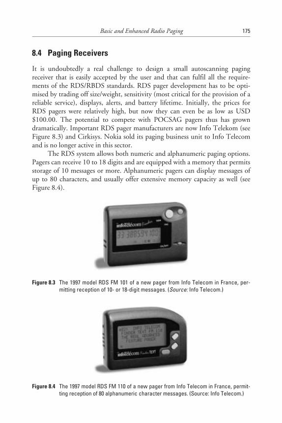
8.4 Paging Receivers
It is undoubtedly a real challenge to design a small autoscanning pagingreceiver that is easily accepted by the user and that can fulfil all the require-ments of the RDS/RBDS standards. RDS pager development has to be opti-mised by trading off size/weight, sensitivity (most critical for the provision of areliable service), displays, alerts, and battery lifetime. Initially, the prices forRDS pagers were relatively high, but now they can even be as low as USD$100.00. The potential to compete with POCSAG pagers thus has growndramatically. Important RDS pager manufacturers are now Info Telekom (seeFigure 8.3) and Cirkisys. Nokia sold its paging business unit to Info Telecomand is no longer active in this sector.
The RDS system allows both numeric and alphanumeric paging options.Pagers can receive 10 to 18 digits and are equipped with a memory that permitsstorage of 10 messages or more. Alphanumeric pagers can display messages ofup to 80 characters, and usually offer extensive memory capacity as well (seeFigure 8.4).
Basic and Enhanced Radio Paging 175
Figure 8.3 The 1997 model RDS FM 101 of a new pager from Info Telecom in France, per-mitting reception of 10- or 18-digit messages. (Source: Info Telecom.)
Figure 8.4 The 1997 model RDS FM 110 of a new pager from Info Telecom in France, permit-ting reception of 80 alphanumeric character messages. (Source: Info Telecom.)

Each RDS Radio Paging transmission includes the country code and thegroup code of the pager, with which the pager synchronises itself. To preservethe battery life, the processor of the pager turns the pager on and off asrequired. The pager is only fully powered during the transmission of pagingmessages to its own interval.
8.5 Future Developments
All operators and manufacturers involved in RDS paging collaborate closelywithin the Radio Paging Association, which is part of the RDS Forum. Thesecompanies drive the technology and are thus the leaders in the worldwide mar-ket of FM Radio Paging. Apart from RDS paging, this market also uses someother technologies such as MBS [5], which is of special interest only to thosewho use FM broadcast transmitters that are operated outside the VHF/FMBand II (87.5–108.0 MHz); that is, mainly in countries of Central and EasternEurope that still use the VHF Band I (66–74 MHz) for FM sound broadcast-ing and where RDS cannot be implemented.
Another proprietary system widely used in the United States and Canadais the system operated by Cue Network called MMBS, which consists of datamultiplexed together with the RDS data stream using the offset word 0. Thissystem can only be used in conjunction with the North American RBDS stan-dard and is not included in the CENELEC RDS standard.
More recently, FM paging has also been implemented in a few cases onthe DARC/SWIFT subcarrier system (see also Chapter 13), which offers amuch higher usable data rate than RDS.
8.6 Conclusions
In a world where mobile communications embracing mobile telephone tech-nology such as GSM are becoming a part of everyday life, one fact remains:there is invariably a cost versus coverage equation to be balanced for bothoperators and subscribers. Today, the RDS paging network can give the opera-tor national and even international coverage when linked to other operatorsworldwide. RDS paging offers a very competitive communication service topotential customer groups who rely on keeping in contact within a wide area asthey travel. Pocket pagers are easy to carry and have such a low power con-sumption that one single AA or two AAA battery cells can power them for asmuch as 1,000 hours or more. There are many other paging technologiesaround that seem to compete with RDS paging; however, with a recent sharp
176 RDS: The Radio Data System
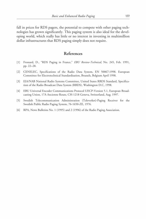
fall in prices for RDS pagers, the potential to compete with other paging tech-nologies has grown significantly. This paging system is also ideal for the devel-oping world, which really has little or no interest in investing in multimilliondollar infrastructures that RDS paging simply does not require.
References
[1] Frossard, D., “RDS Paging in France,” EBU Review-Technical, No. 245, Feb. 1991,pp. 22–28.
[2] CENELEC, Specifications of the Radio Data System, EN 50067:1998. EuropeanCommittee for Electrotechnical Standardisation, Brussels, Belgium April 1998.
[3] EIA/NAB National Radio Systems Committee, United States RBDS Standard, Specifica-tion of the Radio Broadcast Data System (RBDS), Washington D.C, 1998.
[4] EBU Universal Encoder Communications Protocol UECP-Version 5.1, European Broad-casting Union, 17A Ancienne Route, CH-1218 Geneva, Switzerland, Aug. 1997.
[5] Swedish Telecommunication Administration (Televerket)-Paging Receiver for theSwedish Public Radio Paging System, 76-1650-ZE, 1976.
[6] RPA, News Bulletins No. 1 (1995) and 2 (1996) of the Radio Paging Association.
Basic and Enhanced Radio Paging 177
9Open Data Applications (ODA)
9.1 Introduction
This chapter describes the Open Data Applications (ODA) feature that wasdeveloped by the RDS Forum to meet a service provider requirement—to useRDS for data services that would be developed after publication and during therelatively long life of the RDS and the RBDS standards. A particular motiva-tion was to facilitate the development of RDS-TMC (within the CEN stan-dardisation processes) using ODA. But other uses have already emerged—somewhere a service provider wishes to make the use public and others where theservice details are kept private, perhaps because it will be offered as a subscribedservice.
9.2 The Concept and Availability of the ODA Feature
The ODA feature was developed to allow data applications not previouslyspecified in EN 50067:1992 to be conveyed in an RDS data stream with mini-mal difficulty. The ODA feature, specified in EN 50067:1998, permits anumber of predetermined groups types to be used, and these have to be indi-cated in any RDS transmission using the ODA application identification(AID) feature to allow decoders to monitor for them and then decode the rele-vant data. A wide variety of groups are available for use by ODA data services,and these may be selected by a transmission operator at his or her convenience.The service is identified in the associated type 3A groups in the same RDS datastream. Group types shown in Table 9.1 are available for ODA. Some can only
179
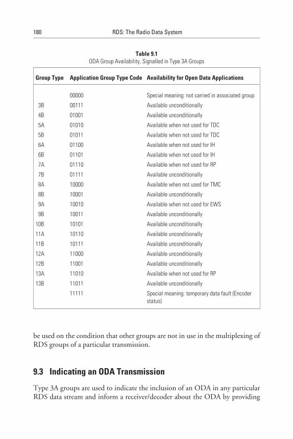
be used on the condition that other groups are not in use in the multiplexing ofRDS groups of a particular transmission.
9.3 Indicating an ODA Transmission
Type 3A groups are used to indicate the inclusion of an ODA in any particularRDS data stream and inform a receiver/decoder about the ODA by providing
180 RDS: The Radio Data System
Table 9.1ODA Group Availability, Signalled in Type 3A Groups
Group Type Application Group Type Code Availability for Open Data Applications
00000 Special meaning: not carried in associated group
3B 00111 Available unconditionally
4B 01001 Available unconditionally
5A 01010 Available when not used for TDC
5B 01011 Available when not used for TDC
6A 01100 Available when not used for IH
6B 01101 Available when not used for IH
7A 01110 Available when not used for RP
7B 01111 Available unconditionally
8A 10000 Available when not used for TMC
8B 10001 Available unconditionally
9A 10010 Available when not used for EWS
9B 10011 Available unconditionally
10B 10101 Available unconditionally
11A 10110 Available unconditionally
11B 10111 Available unconditionally
12A 11000 Available unconditionally
12B 11001 Available unconditionally
13A 11010 Available when not used for RP
13B 11011 Available unconditionally
11111 Special meaning: temporary data fault (Encoderstatus)
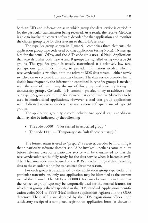
both an AID and information as to which group the data service is carried infor the particular transmission being received. As a result, the receiver/decoderis able to invoke the correct software decoder for that application and monitorthe chosen group type for data relevant to that ODA service.
The type 3A group shown in Figure 9.1 comprises three elements: theapplication group type code used by that application (using 5 bits), 16 messagebits for the actual ODA, and the AID code (this uses 16 bits). Applicationsthat actively utilise both type A and B groups are signalled using two type 3Agroups. The type 3A group is usually transmitted at a relatively low rate,perhaps one group per minute, to provide information needed when areceiver/decoder is switched onto the relevant RDS data stream—either newlyswitched on or vectored from another channel. The data service provider has todecide how frequently the information contained in type 3A groups is needed,with the view of minimising the use of this group and avoiding taking upunnecessary groups. Generally, it is common practice to try to achieve aboutone type 3A group per minute for services that expect receiver/decoders to beused in nondedicated applications. However, closed user group applicationswith dedicated receiver/decoders may use a more infrequent use of type 3Agroups.
The application group type code includes two special status conditionsthat may also be indicated by the following:
• The code 00000—“Not carried in associated group.”
• The code 11111—“Temporary data fault (Encoder status).”
The former status is used to “prepare” a receiver/decoder by informing itthat a particular software decoder should be invoked—perhaps some minutesbefore relevant data for a particular service will be transmitted so that thereceiver/decoder can be fully ready for the data service when it becomes avail-able. The latter code may be used by the RDS encoder to signal that incomingdata to the encoder cannot be transmitted for some reason.
For each group type addressed by the application group type codes of aparticular transmission, only one application may be identified as the currentuser of the channel. The AID code 0000 (Hex) may be used to indicate thatthe respective group type may be temporarily used for the normal features forwhich that group is already specified in the RDS standard. Application identifi-cation codes 0001 to FFFF (Hex) indicate applications registered in the ODAdirectory. These AIDs are allocated by the RDS registrations offices uponsatisfactory receipt of a completed registration application form (as shown in
Open Data Applications (ODA) 181
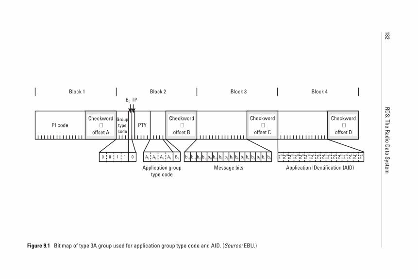
182RDS:The
RadioData
System
0 0 011
Application grouptype code
Message bits Application IDentification (AID)
A3 A2 B0A0A1 b0b15 b14 b13 b12 b11 b10 b9 b8 b7 b6 b5 b4 b3 b2 b1 215 214 213 212 211 210 29 28 27 26 25 24 23 22 21 20
PI code PTY
Block 1 Block 2 Block 3 Block 4
Checkword+
offset A
Checkword+
offset B
Checkword+
offset C
Checkword+
offset D
B0 TP
Grouptypecode
Figure 9.1 Bit map of type 3A group used for application group type code and AID. (Source: EBU.)
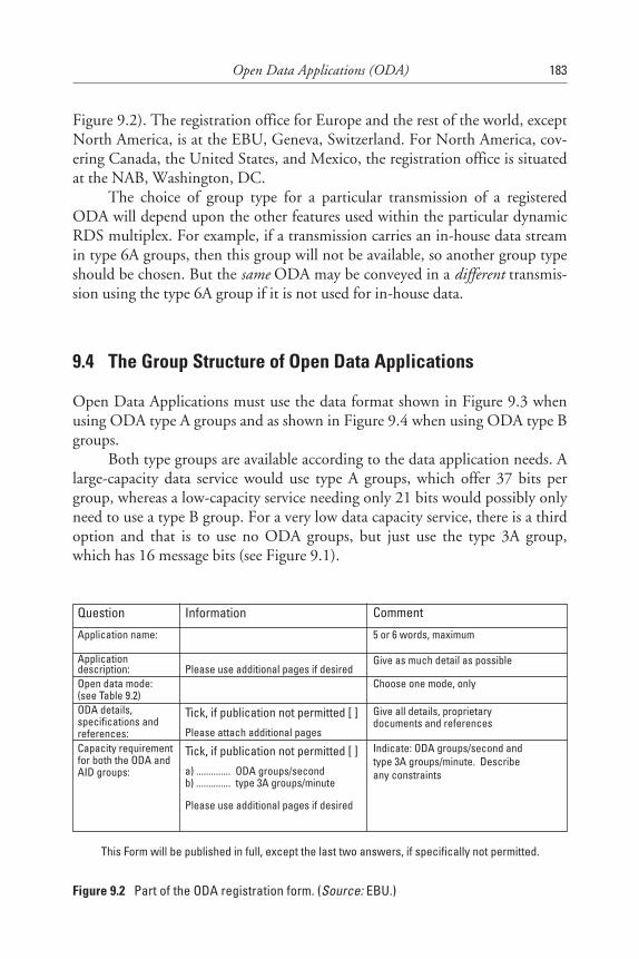
Figure 9.2). The registration office for Europe and the rest of the world, exceptNorth America, is at the EBU, Geneva, Switzerland. For North America, cov-ering Canada, the United States, and Mexico, the registration office is situatedat the NAB, Washington, DC.
The choice of group type for a particular transmission of a registeredODA will depend upon the other features used within the particular dynamicRDS multiplex. For example, if a transmission carries an in-house data streamin type 6A groups, then this group will not be available, so another group typeshould be chosen. But the same ODA may be conveyed in a different transmis-sion using the type 6A group if it is not used for in-house data.
9.4 The Group Structure of Open Data Applications
Open Data Applications must use the data format shown in Figure 9.3 whenusing ODA type A groups and as shown in Figure 9.4 when using ODA type Bgroups.
Both type groups are available according to the data application needs. Alarge-capacity data service would use type A groups, which offer 37 bits pergroup, whereas a low-capacity service needing only 21 bits would possibly onlyneed to use a type B group. For a very low data capacity service, there is a thirdoption and that is to use no ODA groups, but just use the type 3A group,which has 16 message bits (see Figure 9.1).
Open Data Applications (ODA) 183
Question Information Comment
Application name: 5 or 6 words, maximum
Applicationdescription: Please use additional pages if desired
Give as much detail as possible
Open data mode:(see Table 9.2)
Choose one mode, only
ODA details,specifications andreferences:
Tick, if publication not permitted [ ]Please attach additional pages
Give all details, proprietarydocuments and references
Capacity requirementfor both the ODA andAID groups:
Tick, if publication not permitted [ ]
a) .............. ODA groups/secondb) .............. type 3A groups/minute
Please use additional pages if desired
Indicate: ODA groups/second andtype 3A groups/minute. Describeany constraints
This Form will be published in full, except the last two answers, if specifically not permitted.
Figure 9.2 Part of the ODA registration form. (Source: EBU.)
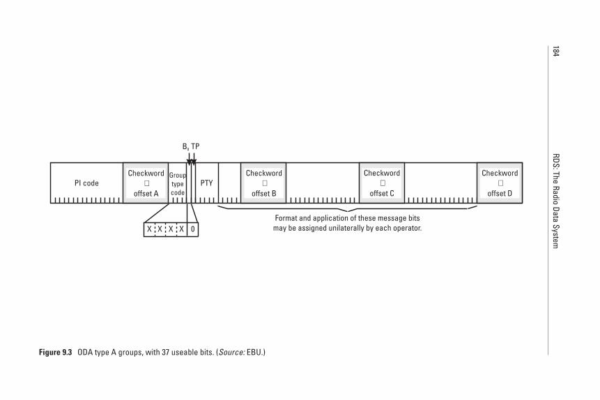
184RDS:The
RadioData
System
PI code PTY
Format and application of these message bitsmay be assigned unilaterally by each operator.
Checkword+
offset A
Checkword+
offset B
Checkword+
offset C
Checkword+
offset D
B0 TP
Grouptypecode
X X 0XX
Figure 9.3 ODA type A groups, with 37 useable bits. (Source: EBU.)
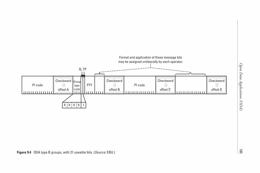
Open
Data
Applications(O
DA
)185
PI code PTYCheckword
+offset A
Checkword+
offset B
Checkword+
offset C'
Checkword+
offset D
B0 TP
Grouptypecode
X X 1XX
PI code
Format and application of these message bitsmay be assigned unilaterally by each operator.
Figure 9.4 ODA type B groups, with 21 useable bits. (Source: EBU.)
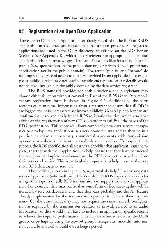
9.5 Registration of an Open Data Application
There are no Open Data Applications explicitly specified in the RDS or RBDSstandards. Instead, they are subject to a registration process. All registeredapplications are listed in the ODA directory, (published on the RDS ForumWeb site (see Appendix K), which makes reference to appropriate companionstandards and/or normative specifications. These specifications may either bepublic (i.e., specification in the public domain) or private (i.e., a proprietaryspecification not in the public domain). The terms “public” and “private” donot imply the degree of access to services provided by an application; for exam-ple, a public service may necessarily include encryption, so the details wouldnot be made available in the public domain by the data service registrant.
The RDS standard provides for both situations, and a registrant maychoose either situation without constraint. Part of the RDS Open Data Appli-cations registration form is shown in Figure 9.2. Additionally, the formrequires quite minimal information from a registrant to ensure that all ODAsare logged and basic parameters are known publicly. Generally, applications areconfirmed quickly and easily by the RDS registrations office, which also givesadvice on the requirements of new ODAs, in order to satisfy all the needs of theRDS specification. This approach allows completely new data services compa-nies to develop new applications in a very economic way and to then be in aposition to make the necessary commercial agreements with transmissionoperators anywhere they want to establish their services. To support thisprocess, the RDS specification also carries a checklist that applicants must com-plete, together with their application, to help ensure that they have consideredthe best possible implementation—from the RDS perspective as well as fromtheir service objective. This is particularly important to help preserve the verysmall RDS data capacity resource.
The checklist, shown in Figure 9.5, is particularly helpful in advising dataservice applicants (who will probably not also be RDS experts) to considerusing other aspects of (all) RDS transmissions to support their service applica-tion. For example, they may realise that some form of frequency agility will beneeded by receiver/decoders, and that they can probably use the AF featurealready implemented by the transmission operator to achieve their require-ment. On the other hand, they may not require the same network configura-tion as required by the transmission operator to provide service to an audiobroadcaster, so they would then have to include an application specific regimeto achieve the required performance. This may be achieved either in the ODAgroups or perhaps by using the type 3A group message bits, since this informa-tion could be allowed to build over a longer period.
186 RDS: The Radio Data System
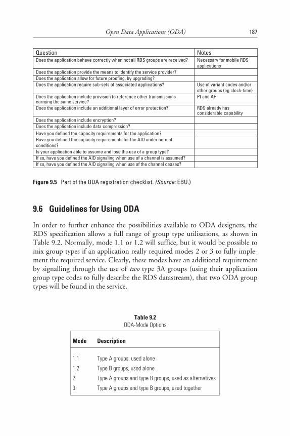
9.6 Guidelines for Using ODA
In order to further enhance the possibilities available to ODA designers, theRDS specification allows a full range of group type utilisations, as shown inTable 9.2. Normally, mode 1.1 or 1.2 will suffice, but it would be possible tomix group types if an application really required modes 2 or 3 to fully imple-ment the required service. Clearly, these modes have an additional requirementby signalling through the use of two type 3A groups (using their applicationgroup type codes to fully describe the RDS datastream), that two ODA grouptypes will be found in the service.
Open Data Applications (ODA) 187
Question NotesDoes the application behave correctly when not all RDS groups are received? Necessary for mobile RDS
applicationsDoes the application provide the means to identify the service provider?Does the application allow for future proofing, by upgrading?Does the application require sub-sets of associated applications? Use of variant codes and/or
other groups (eg clock-time)Does the application include provision to reference other transmissionscarrying the same service?
PI and AF
Does the application include an additional layer of error protection? RDS already hasconsiderable capability
Does the application include encryption?Does the application include data compression?Have you defined the capacity requirements for the application?Have you defined the capacity requirements for the AID under normalconditions?Is your application able to assume and lose the use of a group type?If so, have you defined the AID signaling when use of a channel is assumed?If so, have you defined the AID signaling when use of the channel ceases?
Figure 9.5 Part of the ODA registration checklist. (Source: EBU.)
Table 9.2ODA-Mode Options
Mode Description
1.1 Type A groups, used alone
1.2 Type B groups, used alone
2 Type A groups and type B groups, used as alternatives
3 Type A groups and type B groups, used together

To ensure reliable data reception—for example, in the mobile receptionconditions—it is recommended that data groups be repeated at least threetimes. The received blocks can then be compared bit-by-bit for acceptance, or ifthe message spans over several blocks or groups, one can use a two-byte cyclicredundancy to check in the last block for that whole message. If one byte ineach group is reserved for message identification and as a counter, the groupscould be mixed in any order and still be correctly decoded.
188 RDS: The Radio Data System
10Differential GPS
10.1 Introduction
Using RDS for Differential Global Positioning Systems (DGPS) has become areality in a large number of countries. However, although this issue has gener-ated a relatively wide interest since the early 1990s—and implementation issueswere widely discussed in both the RDS Forum and the U.S. National RadioSystems Committee—due to diverse commercial interests, no common stan-dard has ever emerged. Ultimately, the new ODA feature was commonly iden-tified as being most suitable to carry such a service.
This chapter describes the technological issues that need to be consideredif one wants to implement DGPS within RDS. Such a decision would also haveto take into account other alternative technologies that either achieve the sameor even better results than those that one can now achieve with RDS. Interna-tionally, continuous DGPS services that could, for example, serve Europeanroad users do not appear to be possible using RDS because of subscription andinstitutional challenges, which would require too much bandwidth to achievesatisfactory results.
In addition, one should also realise that whatever solution is adopted, itwill probably only permit a relatively small market sector to be developed.
10.2 Positioning With GPS
The Global Positioning System is a worldwide satellite positioning/locationsystem developed for military use by the U.S. Department of Defense (DoD).
189
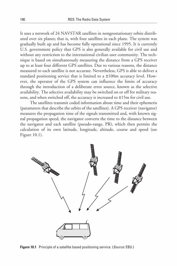
It uses a network of 24 NAVSTAR satellites in nongeostationary orbits distrib-uted over six planes; that is, with four satellites in each plane. The system wasgradually built up and has become fully operational since 1995. It is currentlyU.S. government policy that GPS is also generally available for civil use andwithout any restriction to the international civilian user community. The tech-nique is based on simultaneously measuring the distance from a GPS receiverup to at least four different GPS satellites. Due to various reasons, the distancemeasured to each satellite is not accurate. Nevertheless, GPS is able to deliver astandard positioning service that is limited to a ±100m accuracy level. How-ever, the operator of the GPS system can influence the limits of accuracythrough the introduction of a deliberate error source, known as the selectiveavailability. The selective availability may be switched on or off for military rea-sons, and when switched off, the accuracy is increased to ±15m for civil use.
The satellites transmit coded information about time and their ephemeris(parameters that describe the orbits of the satellites). A GPS receiver (navigator)measures the propagation time of the signals transmitted and, with known sig-nal propagation speed, the navigator converts the time to the distance betweenthe navigator and each satellite (pseudo-range, PR), which then permits thecalculation of its own latitude, longitude, altitude, course and speed (seeFigure 10.1).
190 RDS: The Radio Data System
Figure 10.1 Principle of a satellite based positioning service. (Source: EBU.)
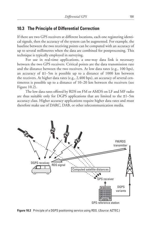
10.3 The Principle of Differential Correction
If there are two GPS receivers at different locations, each one registering identi-cal signals, then the accuracy of the system can be augmented. For example, thebaseline between the two receiving points can be computed with an accuracy ofup to several millimetres when the data are combined for postprocessing. Thistechnique is typically employed in surveying.
For use in real-time applications, a one-way data link is necessarybetween the two GPS receivers. Critical points are the data transmission rateand the distance between the two receivers. At low data rates (e.g., 100 bps),an accuracy of ±1–5m is possible up to a distance of 1000 km betweenthe receivers. At higher data rates (e.g., 2,400 bps), an accuracy of several cen-timetres is possible up to a distance of 10–20 km between the receivers (seeFigure 10.2).
The low data rates offered by RDS on FM or AMDS on LF and MF radioare thus suitable only for DGPS applications that are limited to the ±1–5maccuracy class. Higher accuracy applications require higher data rates and musttherefore make use of DARC, DAB, or other telecommunication media.
Differential GPS 191
DGPS receiver
GPS receiver
RDS signalComputed satellite distances
FM/RDStransmitter
DGPSvariants
GPS reference station
Figure 10.2 Principle of a DGPS positioning service using RDS. (Source: AZTEC.)
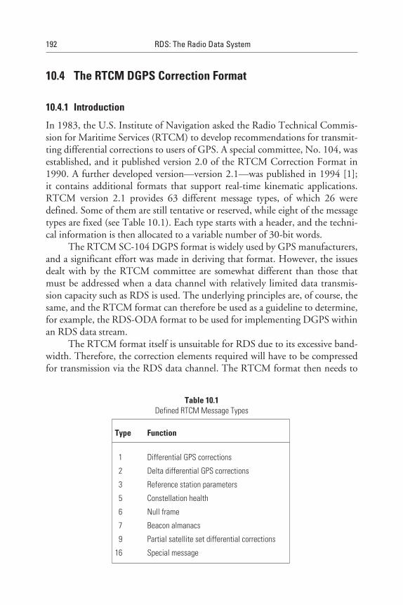
10.4 The RTCM DGPS Correction Format
10.4.1 Introduction
In 1983, the U.S. Institute of Navigation asked the Radio Technical Commis-sion for Maritime Services (RTCM) to develop recommendations for transmit-ting differential corrections to users of GPS. A special committee, No. 104, wasestablished, and it published version 2.0 of the RTCM Correction Format in1990. A further developed version—version 2.1—was published in 1994 [1];it contains additional formats that support real-time kinematic applications.RTCM version 2.1 provides 63 different message types, of which 26 weredefined. Some of them are still tentative or reserved, while eight of the messagetypes are fixed (see Table 10.1). Each type starts with a header, and the techni-cal information is then allocated to a variable number of 30-bit words.
The RTCM SC-104 DGPS format is widely used by GPS manufacturers,and a significant effort was made in deriving that format. However, the issuesdealt with by the RTCM committee are somewhat different than those thatmust be addressed when a data channel with relatively limited data transmis-sion capacity such as RDS is used. The underlying principles are, of course, thesame, and the RTCM format can therefore be used as a guideline to determine,for example, the RDS-ODA format to be used for implementing DGPS withinan RDS data stream.
The RTCM format itself is unsuitable for RDS due to its excessive band-width. Therefore, the correction elements required will have to be compressedfor transmission via the RDS data channel. The RTCM format then needs to
192 RDS: The Radio Data System
Table 10.1Defined RTCM Message Types
Type Function
1 Differential GPS corrections
2 Delta differential GPS corrections
3 Reference station parameters
5 Constellation health
6 Null frame
7 Beacon almanacs
9 Partial satellite set differential corrections
16 Special message
be reconstructed within a special service-provider-specific DGPS RDS FMsubcarrier receiver before the correction data is delivered to the navigator. Forexample, to achieve a ±5m accuracy, 20 to 50 bps within RDS-ODA to carrythe correction data will be sufficient. Remember, as explained in Chapter 9,one ODA group type A (e.g., type 11A group) can carry 37 bits for the applica-tion under consideration.
10.4.2 Required Data Elements
Differential GPS requires that certain types of information be available to theDGPS navigator [2]. In the following, some of the most important elementscommonly used by DGPS service providers and based on RTCM formats arebriefly explained.
10.4.2.1 Pseudo-Range Correction (PRC)The pseudo-range correction is the most fundamental data item needed by thenavigator. It describes the correction for a satellite that should be applied at acertain point of time (the time at which the pseudo-range measurements weremade at the reference station). The PRCs are strictly only valid for the epochwhen they are computed at the reference station. When the PRC is transmittedto a mobile user, time goes by, and the values grow older and deviate more andmore from the actual value. To overcome this, a reference station makes a pre-diction about the rate of change of the PRC, which is called the range rate cor-rection (RRC).
10.4.2.2 Range Rate Correction (RRC)The RRC is used by the navigators to propagate the PRC forward to the pointin time at which it can be applied by the navigator. Since the PRC was gener-ated at a time in the past and a variable time was required for it to be transmit-ted and received by the navigators, the rate term provides the means for thecorrection to be made current at the navigator.
The composite PRC computed by the navigators from the PRC and RRCterms is in error to the extent that unmodelled effects cause the actual pseudo-range correction to differ from the computed pseudo-range correction. Themost significant source of error is selective availability.
10.4.2.3 Age of Correction Data: Time of Correction with the ModifiedZ-Count
The correction PRC and correction rate RRC for a satellite are useless unlessthe times for which they were computed are also conveyed to the navigators.
Differential GPS 193
In RTCM, the list of PRCs and RRCs for all satellites is therefore con-nected with the epoch of their creation, called “modified z-count,” whichcounts the seconds of the current hour. A user DGPS receiver calculates thepseudo-ranges for the epoch in which it can use them. The predicted andbroadcast values of RRC grow worse the older they are, such that accuracydegrades significantly with values older than 20–25 seconds.
10.4.2.4 Satellite Identification (SATID)The correction information for each satellite is different, and there is no assur-ance that corrections are received by all navigators. Therefore, it is necessary toidentify the satellite whose corrections are being transmitted.
10.4.2.5 Ephemeris ParametersThe ephemeris is a set of parameters that describe the orbits of the satellites.The ephemeris information for each satellite is changed periodically (approxi-mately every one to two hours). The DGPS correction information is based ona particular ephemeris, available to the reference station when the correction isgenerated. It is necessary to advise the navigators of the ephemeris in use at thereference station when the corrections were computed, because the correctionsmay be properly used by the navigator only if the same ephemeris is employed.
The issue of data ephemeris (IODE) is the key that ensures that the userequipment calculations and the reference station corrections are based on thesame set of orbital and clock parameters.
10.4.2.6 User Differential Range Error (UDRE)It is important for the reference station to advise the navigators of the validityand approximate error in the differential corrections. This information permitsthe navigators to decide whether or not to use the correction from a particularsatellite and how the satellite may be weighted in the position computation.
10.4.2.7 Reference Station Location Data: Station ID and XYZ CoordinatesIn general, it is useful for the navigators to know the location of the referencestation. This permits the navigators to use ionospheric and tropospheric modelsto estimate the amount of error in the pseudo-range measurements mode atboth the reference station and the navigator.
This cannot be done at the reference station since the navigator locationsare unknown to the reference station and there is no consistent model availablefor either troposphere or ionosphere that is accepted by all GPS manufacturers.For this reason, no ionospheric or tropospheric models are used at the referencestation.
194 RDS: The Radio Data System
In the RDS case, it is assumed that the reference station is relatively closeto the FM transmitter. The limited range of most FM stations (about 100 km)implies that the navigators will not be far from the transmitter. Hence, a userclose enough to receive the FM station will generally be well within the range atwhich the differential corrections are accurate. These arguments indicate thatthere may not be a strong need for the navigators to know the location of thereference station.
However, the reference station altitude may be useful, because the atmos-pheric models that are commonly used require the altitude of both thereference station and the navigator. The tendency to site FM transmitters atrelatively high locations to improve signal coverage tends to increase the needfor reference station altitude.
10.4.2.8 Service Quality Parameter: SQ/Station HealthThis DGPS format offers positioning service providers the possibility for serv-ices with different accuracies, depending on the frequency at which correctionsare supplied. An indication in the messages is given to advise navigators of theexpected accuracy of the service. The service quality parameter, Station Healthprovides this capability.
10.5 How RDS can be Used for Differential GPS
10.5.1 Design Considerations
For an average number of satellites, the type 1 RTCM message (the mostimportant and most frequently transmitted message) is 500 to 700 bitslong (e.g., 680 bits for nine satellites) and is split into independent parts. Fora DGPS service within RDS, this data has to be rearranged so that the dataconcerning each individual satellite requires only 37 bits and can therefore beconveyed in one RDS group. Additional overhead information, which is neces-sary to reconstruct the exact RTCM message, is required only a few times perminute.
This rearrangement of the satellite data guarantees a stabilised evaluationof the data. As already noted, to transmit the original RTCM format takes along time. By creating self-sufficient or autonomous groups, only the informa-tion relating to one satellite can be affected by transmission errors such as thosecaused by multipath propagation—the rest of the data remains undisturbed.
PRCs are not transmitted with their actual value, but are related to thelast integer minute by means of the RRC. The mobile station has to reconstruct
Differential GPS 195
the current value of the PRC by using its own clock. Thus, the frequent trans-mission of the z-count can be avoided and the PRCs become nearly independ-ent of any overhead information. The data for nine satellites need 9 × 37 = 333bits, instead of the 680 bits needed by the original RTCM correction format.
When the RDS-ODA data format is used to transmit DGPS informa-tion, the AID and application group type code will be transmitted relativelyinfrequently in type 3A groups (i.e., once per minute). The DGPS correctiondata will then be mapped into the 37 available bits of the application grouptype (e.g., the type 11A group). Figure 10.3 [3] shows an example of how this isdone in principle, that is taken from the German RASANT system [4]. To beable to determine the size for the RTCM data elements described above, it isnecessary to decide how many bits will be required to map the information intothe RDS-ODA application group. This decision implies that some kind ofreduction for the RTCM data elements will be used that takes into account theavailable data transmission rate (limited in a practical implementation to onlyone or two RDS-ODA application groups per second) and the few correspond-ing bits thus available in these groups.
Each service provider has to decide this data format specifically for theservice to be provided. Therefore, the DGPS RDS decoder that the end userwishes to use will always be specific to the particular service provider in spiteof the fact that the GPS navigator uses standardised RTCM-formatted DGPScorrection data. The DGPS RDS special receiver thus has to supply the correc-tion data as input to the GPS navigator in the format of the RTCM standard.
Neither the RDS standard nor the RBDS standard contains an open stan-dard for implementing DGPS. This is due to the fact that at the time whenthe RDS-ODA specifications were drawn up within the RDS Forum in 1995,DGPS using RDS as a data transport mechanism was already implemented inseveral countries—or at least at a very advanced state of system design. Severalservice providers were competing with similar but different proprietary dataformats and advocating open and encrypted DGPS services. Because of this, noagreement was reached to include an open DGPS standard into the RDS/RBDSstandards, both under revision at that time for the purpose of upgrading. All thatcould be achieved was that there was general agreement that RDS-ODA wouldprovide a suitable means to achieve DGPS implementation within RDS.
10.5.2 Service Examples
10.5.2.1 RASANT in Germany
In May 1995, the Working Committee of the Surveying and MappingAuthorities of the Federal Republic of Germany decided to introduce a real-
196 RDS: The Radio Data System
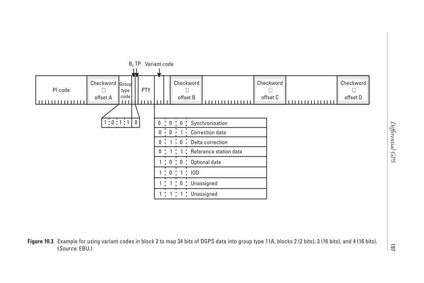
DifferentialG
PS197
1 0 0 0
0
0 0
0
0
0
0
0
0
0 01
1
1
1
1
1
1
1 1 1
1
1
1
1
PI code PTY
Variant code
Checkword+
offset A
Checkword+
offset B
Checkword+
offset C
Checkword+
offset D
B0 TP
Grouptypecode
Synchronisation
Correction data
Delta correction
Reference station data
Optional data
IOD
Unassigned
Unassigned
Figure 10.3 Example for using variant codes in block 2 to map 34 bits of DGPS data into group type 11A, blocks 2 (2 bits), 3 (16 bits), and 4 (16 bits).(Source: EBU.)

time DGPS service throughout the country. Radio Aided Satellite NavigationTechnique (RASANT), which has been developed by the WestdeutscherRundfunk (WDR) and the Landesvermessungsamt Nordrhein-Westfalen (thesurveying and mapping agency of Northrhine Westfalia), uses RDS-ODA asthe additional data channel. The service will be available from 1998 as an openservice, and it will be financed by a one-time fee paid by the user, which isincluded in the price of the RASANT decoders available from several suppliersin Germany.
The RASANT technique can process and transmit the complete varietyof RTCM messages via RDS. However, due to the low data rate of the presentRDS service, RTCM message types 1, 2, 3, 5, 9, and 16 are modified and con-veyed in an appropriate DGPS format, called DGPS variants.
Nearly all types of GPS receivers with DGPS capability can add thesePRCs to their own pseudo-ranges and improve the positional accuracy from100m down to between 1 and 3m. For the proven accuracy level of ±1–3m, anRDS capacity of one group per second is sufficient. In this case, the mainDGPS variants, as shown in Figure 10.3, are supported. More capacity isrequired if additional variants are used (e.g., the alternative frequencies of thetransmitters that carry a RASANT service).
10.5.2.2 EPOS in Sweden
Teracom, the Swedish transmission operator of the four national FM radio net-works, introduced a DGPS service called EPOS at the end of 1994. EPOSis available as a basic service with a ±10m accuracy and as a premium serviceoffering an impressive ±2m accuracy—both claimed with 95% confidence.The differential corrections for the GPS system are made available via the RDSchannel all over Sweden through a renewable annual customer subscription andusing modified RDS receivers (an EPOS receiver) purchased by the customers.
There are 12 EPOS service GPS reference stations, co-located with someof the Swedish land survey sites throughout Sweden to generate local differen-tial corrections. These are first preprocessed and then all forwarded to a centralconcentrator and RDS network server situated at the operations centre (OPC)for the entire national radio and TV services located in Stockholm.
A multidrop network then redistributes the real-time stream of differen-tial corrections to the matching local FM transmitter sites throughout Sweden.At each transmitter site, the corrections are inserted into RDS type 11A groups.There is a very short delay—less than one second—between the calculation ofthe differential corrections at the various reference stations and their receptionby the EPOS receiver. Integrity monitoring and backup functions for the
198 RDS: The Radio Data System

EPOS service are all incorporated in the system, and they are also supervisedand operated by OPC.
The commercial service is much more than just the technical infrastruc-ture described. Considerable effort was therefore invested in the design andimplementation of a custom-made subscriber management system for the han-dling of customer subscriptions and other administrative functions. Gatewaysto Teracom´s existing customer and invoicing routines were also established.The new data system even allows the customer—in addition to Teracom—toaddress and initiate his or her own EPOS receiver via the FM RDS network forthe purchased service accuracy and subscription duration once the invoice hasbeen paid. Distribution and sales of the EPOS service and the associated choiceof receivers will be accomplished through cooperation with existing wholesaleand retail outlets already selling GPS equipment.
10.6 Other Alternatives
10.6.1 Maritime Radio Beacons
The International Association of Lighthouse Authorities (IALA) has drawn upa frequency plan for maritime radio beacons to broadcast DGPS data. Imple-mentations of this type already exist in several European countries where some50 beacons are planned, with most of them operational since 1994/95 andbroadcasting DGPS data with a bit rate of 200 bps. The coverage range of thesetransmitters is on the order of 200 km. The accuracy achieved is claimed to bebetween ±1m and ±5m.
10.6.2 AMDS
Since 1994, AMDS has been used in Germany on LF and MF, mainly ontransmitters from DeutschlandRadio/DLF. AMDS uses a data rate of 200 bps,of which two-thirds is used to distribute DGPS data. The same service is alsobeing tested in field trials conducted in Norway, the Netherlands, and Switzer-land. Encoders and decoders are exclusively available from Bosch/Blaupunkt inGermany. Implementation expertise is available from Technische UniversitätDresden, where the technology used was developed. The accuracy achieved is±1m to ±5m. The coverage areas are very large. For example, the LF transmit-ter at Donebach uses 153 kHz and covers all of Germany, and Beromünsteruses 207 kHz to cover all of Switzerland.
Differential GPS 199
10.6.3 DARC
The relatively high net data rate of 9 kbps achieved with the LMSK-modulatedDARC subcarrier on 76 kHz within an FM multiplex signal allows the provi-sion of advanced GPS services, which may include a DGPS service with a highupdate rate and phase measurements that permit an accuracy of better than10 cm. This was demonstrated during 1996/97 field trials in Austria involvingthe national broadcaster ORF. Similar tests, to be carried out in Norway, arealso planned.[5].
10.7 GLONASS: the Alternative to GPS
Since 1996, the Russian Federation has been operating a system similar to GPS,called GLONASS. That system is also available for civilian use, but receivers arenot yet as commonly available as for GPS. They use a different communicationprotocol. The accuracy without differential correction is around ±10m.
10.8 EGNOS: the European Component of GNSS
The Global Navigation Satellite System (GNSS) is an action plan launched bythe European Commission. This plan has two phases [6, 7]:
1. GNSS-1 aims at implementing the European component, EuropeanGeostationary Navigation Overlay Service (EGNOS), which will usethe U.S. GPS and Russian GLONASS signals with an augmentation(differential GNSS) of their integrity and accuracy by an additionalground- and space-based infrastructure scheduled to be in opera-tion from the year 2000. This project is jointly pursued by theEuropean Commission, the European Space Agency (ESA), andthe European civil aviation control agency Eurocontrol.
2. GNSS-2 is envisaged as a new civil worldwide navigation system thatwill be internationally controlled and managed, and could be a suc-cessor of the existing military systems.
References
[1] RTCM (1994)-Recommended Standards for differential NAVSTAR GPS service, Version2.1, Radio Technical Commission for Maritime Services, Washington D.C, Jan. 3, 1994.
200 RDS: The Radio Data System
[2] Galyean, P., NRSC/RBDS DGPS Working Group—Status report of the coordinator,Torrance, CA, June 3, 1994, Working document of the RDS Forum, 1994.
[3] RDS Forum, Specification of the Radio Data System-Open DGPS, proposed additionalspecification, 1995.
[4] Raven, P., S. Sandmann, and G. Schoemackers, “RASANT Radio Aided SatelliteNavigation Technique,” EBU Review-Technical, No. 267, Spring 1996, pp. 27–31.
[5] Second SWIFT Forum, Lulea, Sweden, Published by Teracom Sweden, 1997.
[6] Global Navigation Satellite System, A brochure published in 1997 by the European GNSSOffice at the European Commission (DG VII-A2) in Brussels, Belgium.
[7] Towards a Trans-European Positioning and Navigation Network, Including a EuropeanStrategy for Global Navigation Satellite Systems (GNSS)-Communication from theCommission to the Council and the European Parliament, COM (1998) 29/21.01.98
Differential GPS 201

11RDS Encoder Communication Protocolsand the UECP
11.1 Introduction
This chapter explains the need for a communication protocol to be usedbetween broadcaster (studios) or data service provider and RDS encoders. TheEBU has developed a standard for this protocol that is commonly called theUniversal Encoder Communication Protocol (UECP). It is especially recom-mended for use when RDS is implemented within a network of several trans-mitters and also when data needs to be assembled from various data serviceproviders. The concept and the data format of this protocol are also describedin some detail.
11.2 Why RDS Encoders Need a Communication Protocol
Transmission operators who want to implement an RDS service need to installRDS encoders. They are normally installed at transmitter sites adjacent to thestereo encoder, which generates a 19 kHz signal that the RDS encoder uses tosynchronise its output RDS data stream.
Two “types” of RDS can be provided: Static RDS services can be pro-vided by an RDS encoder simply providing RDS information, such as a fixedAF list, from internal memory; whereas dynamic RDS services, such as Radio-Text, require data input to an RDS encoder. Even static RDS services may have
203
to be changed from time to time, depending upon the network configurationand the type of radio programme on air.
Dynamic RDS is needed for a number of reasons. RDS data related to theradio programme content (see Chapters 3, 4, and 6) requires a high degreeof control from the on-air studio. In the case of a data service such as TMC,an operator-specific implementation under ODA, or Radio Paging (seeChapters 7–9), a high degree of control is required from the service provider tosupply their data to the RDS encoder—either to a single broadcast transmitteror to a network of broadcast transmitters.
Simple but numerous different commands from the on-air studio or theservice provider have to be sent, via a suitable data link, to the RDS encoder.For example, the on-air studio could change the status of the TP, TA, and MSflags to reflect the programme status. Such commands are often derived from“automated” functions to avoid operator intervention. A single-service broad-caster could possibly use a dedicated audio mixer channel for announcements,so that the MS flag is set to the “speech” condition every time the fader isopened, by using “back” contacts to send a command via the data link.
Once a dynamic RDS encoder has been chosen, then in most situations, aunidirectional data link is only possible for update data to be sent to the RDSencoder. This is due to the fact that for economic reasons, the transmitteroperator had to adapt existing analogue, or even digital, audio distribution net-works, which are essentially unidirectional, to add a data distribution function.
One possibility for implementing a unidirectional data link within anexisting audio distribution network is using a subcarrier just above 15 kHz(nominally the highest audio frequency used in FM broadcasting), and usingthe fact that the audio channel is often designed for a 20 kHz bandwidth. A sys-tem of this kind is the AUDIODAT system, which was developed in Germanyby ARD/SWF. This system has a bit rate of 200 bps. Communication codecequipment for this system is available from RE Technology and Rohde &Schwarz. This allows the audio and data signals to be combined at the studio,carried on the wideband audio circuit and extracted at the transmitter site, andfor the audio to be connected to the stereo encoder and the data to be con-nected to the RDS encoder.
A number of proprietary update protocols were implemented on datalinks between source servers and the RDS encoders; several of them wereencoder manufacturer specific. These protocols were used to send data mes-sages from an RDS controller/management system (or simply an RDS encoderserver) to the RDS encoders. Acknowledgements from the encoder were notessential; instead, it was arranged to send repeats of each message in order toensure their receipt. In this way, a whole range of dynamic RDS features couldbe used by the broadcaster to enhance RDS performance for the listener. In
204 RDS: The Radio Data System
some cases, an RDS encoder controller, running on a PC, has been used to sendupdate messages to the RDS encoder. If a very full implementation is required,a dedicated RDS management computer system, frequently called an RDSserver, has to be used to control on a scheduled basis the whole range ofRDS features, including the radio programme-related data such as TP, TA,PTY, RT, and the full array of EON references.
11.3 Why the EBU and Encoder Manufacturers Developedthe UECP
In the early 1990s, the EBU studied a requirement that the various existingand implemented RDS encoder communication protocols be harmonised.Such harmonisation would then enable broadcasters to purchase RDS systemcomponents (e.g., RDS encoders, RDS server computers, and software) from avariety of sources. This would permit significant economies in network opera-tion, and it would offer the necessary high flexibility to implement in successivestages enhancements to already existing RDS implementations (specifically,within transmitter networks). RDS system component manufacturers wouldthen also be able to integrate their products with those from other manufactur-ers, enabling more complex systems to be produced than those that wouldotherwise have been possible.
These proprietary update protocols had similar functional elements; how-ever, they differed significantly in their environmental models. The structure,functionality, and addressing of their intended networks and the data structureswithin each RDS encoder are often quite different. Therefore, the UniversalEncoder Communication Protocol (UECP) specification, now widely accepted[1], was based on harmonised environmental and encoder models.
The UECP is a layered communication protocol that is in line withthe commonly used OSI reference model (ISO Recommendation 7498). TheUECP in its present version—version 5.1 (August 1997)—encompasses allcurrent RDS features, including the latest TMC specifications [2]. It is alsodesigned to accommodate all new developments that will use the open dataapplications (ODA) concept (see Chapter 9).
The model and protocol also provide a template specification upon whichnew products may be based and, most specifically, it permits other existingencoder communication protocols to be enhanced. Thus, many existing devicescan be adapted to meet the present functionality required. However, it isstrongly recommended that all new RDS encoders should permit communica-tions to also be operated under the UECP protocol (version 5.1 or later). The
RDS Encoder Communication Protocols and the UECP 205
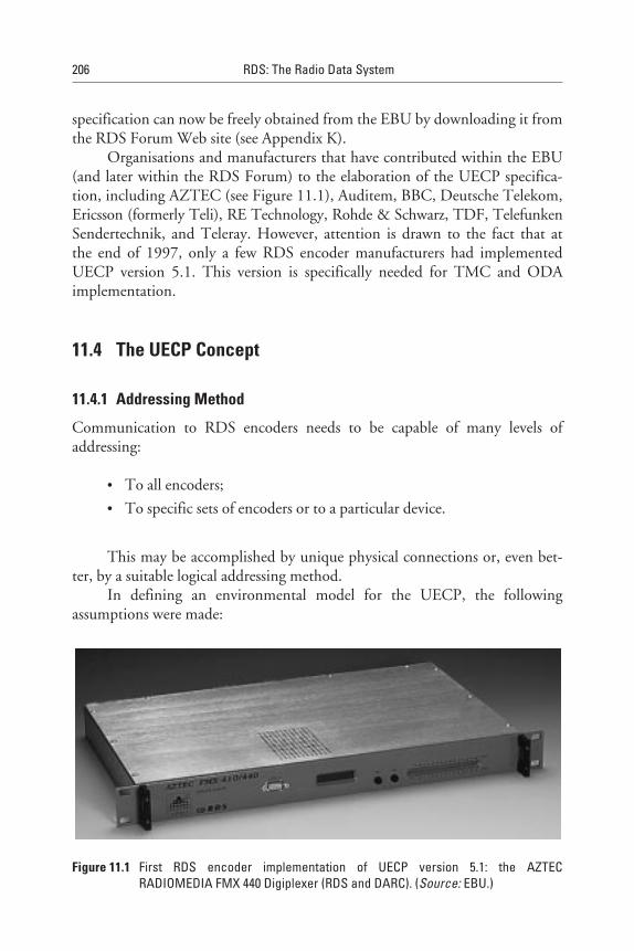
specification can now be freely obtained from the EBU by downloading it fromthe RDS Forum Web site (see Appendix K).
Organisations and manufacturers that have contributed within the EBU(and later within the RDS Forum) to the elaboration of the UECP specifica-tion, including AZTEC (see Figure 11.1), Auditem, BBC, Deutsche Telekom,Ericsson (formerly Teli), RE Technology, Rohde & Schwarz, TDF, TelefunkenSendertechnik, and Teleray. However, attention is drawn to the fact that atthe end of 1997, only a few RDS encoder manufacturers had implementedUECP version 5.1. This version is specifically needed for TMC and ODAimplementation.
11.4 The UECP Concept
11.4.1 Addressing Method
Communication to RDS encoders needs to be capable of many levels ofaddressing:
• To all encoders;
• To specific sets of encoders or to a particular device.
This may be accomplished by unique physical connections or, even bet-ter, by a suitable logical addressing method.
In defining an environmental model for the UECP, the followingassumptions were made:
206 RDS: The Radio Data System
Figure 11.1 First RDS encoder implementation of UECP version 5.1: the AZTECRADIOMEDIA FMX 440 Digiplexer (RDS and DARC). (Source: EBU.)
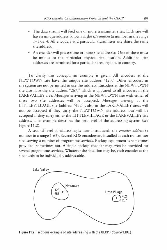
• The data stream will feed one or more transmitter sites. Each site willhave a unique address, known as the site address (a number in the range1–1,023). All encoders at a particular transmitter site share the samesite address.
• An encoder will possess one or more site addresses. One of these mustbe unique to the particular physical site location. Additional siteaddresses are permitted for a particular area, region, or country.
To clarify this concept, an example is given. All encoders at theNEWTOWN site have the unique site address “123.” Other encoders inthe system are not permitted to use this address. Encoders at the NEWTOWNsite also have the site address “267,” which is allocated to all encoders in theLAKEVALLEY area. Messages arriving at the NEWTOWN site with either ofthese two site addresses will be accepted. Messages arriving at theLITTLEVILLAGE site (address “452”), also in the LAKEVALLEY area, willnot be accepted if they carry the NEWTOWN site address, but will beaccepted if they carry either the LITTLEVILLAGE or the LAKEVALLEY siteaddress. This example describes the first level of the addressing system (seeFigure 11.2).
A second level of addressing is now introduced, the encoder address (anumber in a range 1-63). Several RDS encoders are installed at each transmittersite, serving a number of programme services. Backup equipment is sometimesprovided, sometimes not. A single backup encoder may even be provided forseveral programme services. Whatever the situation may be, each encoder at thesite needs to be individually addressable.
RDS Encoder Communication Protocols and the UECP 207
Lake Valley
Newtown
Little Village123267
452267
**
Figure 11.2 Fictitious example of site addressing with the UECP. (Source: EBU.)
An encoder will possess one or more encoder addresses. One must beunique to the encoder at that site. Additional encoder addresses may be assignedaccording to the encoder’s usage or manufacture. However, the site andencoder addresses are not intended to specify a particular radio service. Thespecification of a particular radio service, a third level of addressing, is accom-plished by using a programme service number. The site and encoder addressesshould be thought of as being entirely physical, and are used only to address acertain “box” at a certain location. The functionality of the box is irrelevant inthis context.
It is expected that many messages will be sent to all RDS encoders. Thus,the global number of zero (0) is defined for both the site and encoder addresses.Messages bearing the global site address are deemed to be acceptable at all sitesin the system. Messages bearing the global encoder address are deemed to beacceptable at all RDS encoders at sites specified by the accompanying siteaddress.
An RDS encoder will have two address lists, one of acceptable siteaddresses and the other of acceptable RDS encoder addresses. The site addresslist includes 0 (the global site address), the unique site address, and any addi-tional site group addresses.
The RDS encoder address list includes 0 (the global encoder address), theunique encoder address, and any additional encoder group addresses.
A message is acceptable to a particular RDS encoder only if the siteaddress is contained within its site address list and the RDS encoder address iscontained within its RDS encoder address list.
11.4.2 RDS Encoder Conceptual Model
11.4.2.1 Software ModelMessages are accepted by the RDS encoder in accordance with the addressingmethod described above. Applicability is further determined by optional fieldswithin the message itself (see Figure 11.3). This permits addressing of the fol-lowing structures within an RDS encoder:
• Data sets: An encoder will have one or more data sets, each of whichresults in a particular RDS output. Each data set may refer to manyprogramme services using the RDS EON feature. Only one data set isresponsible at any one time for the encoder’s output, and is knownas the current data set. Data sets are addressed by the protocol asdescribed below.
208 RDS: The Radio Data System
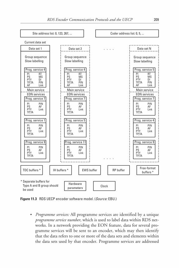
• Programme services: All programme services are identified by a uniqueprogramme service number, which is used to label data within RDS net-works. In a network providing the EON feature, data for several pro-gramme services will be sent to an encoder, which may then identifythat the data refers to one or more of the data sets and elements withinthe data sets used by that encoder. Programme services are addressed
RDS Encoder Communication Protocols and the UECP 209
Group sequenceSlow labelling
Main service Main service Main serviceEON services EON services EON services
Prog. service 4PIPSPTYTP,TAAF
RTMSDIPINLink
PIPSPTYTP,TAAF
RTMSDIPINLink
PIPSPTYTP,TAAF
RTMSDIPINLink
Data set 1 Data set 2
PIPSPTYTP,TA
PINAFLink
PIPSPTYTP,TA
PINAFLink
PIPSPTYTP,TA
PINAFLink
PIPSPTYTP,TA
PINAFLink
PIPSPTYTP,TA
PINAFLink
PIPSPTYTP,TA
PINAFLink
PIPSPTYTP,TA
PINAFLink
PIPSPTYTP,TA
PINAFLink
PIPSPTYTP,TA
PINAFLink
Data set N
Current data set
TDC buffers * IH buffers * EWS buffer RP buffer Free-formatbuffers *
Prog. service 4 Prog. service 5
Prog. service 7 Prog. service 7 Prog. service 7
Prog. service 1 Prog. service 5 Prog. service 4
Prog. service 9 Prog. service 11 Prog. service 9
Group sequenceSlow labelling
Group sequenceSlow labelling
Site address list: 0, 123, 267, ... Coder address list: 0, 5, ...
Hardwareparameters Clock
* Separate buffers forType A and B group shouldbe used
**
Figure 11.3 RDS UECP encoder software model. (Source: EBU.)
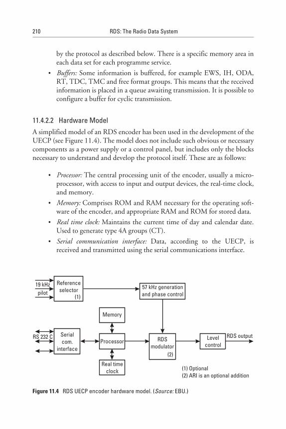
by the protocol as described below. There is a specific memory area ineach data set for each programme service.
• Buffers: Some information is buffered, for example EWS, IH, ODA,RT, TDC, TMC and free format groups. This means that the receivedinformation is placed in a queue awaiting transmission. It is possible toconfigure a buffer for cyclic transmission.
11.4.2.2 Hardware ModelA simplified model of an RDS encoder has been used in the development of theUECP (see Figure 11.4). The model does not include such obvious or necessarycomponents as a power supply or a control panel, but includes only the blocksnecessary to understand and develop the protocol itself. These are as follows:
• Processor: The central processing unit of the encoder, usually a micro-processor, with access to input and output devices, the real-time clock,and memory.
• Memory: Comprises ROM and RAM necessary for the operating soft-ware of the encoder, and appropriate RAM and ROM for stored data.
• Real time clock: Maintains the current time of day and calendar date.Used to generate type 4A groups (CT).
• Serial communication interface: Data, according to the UECP, isreceived and transmitted using the serial communications interface.
210 RDS: The Radio Data System
57 kHz generationand phase control
Referenceselector
19 kHzpilot
Memory
Processor RDSmodulator
Levelcontrol
RDS output
Real timeclock
Serialcom.
interface
(1) Optional(2) ARI is an optional addition
RS 232 C
(1)
(2)
Figure 11.4 RDS UECP encoder hardware model. (Source: EBU.)
• RDS modulator: Produces the RDS biphase signal, and optionally ARIin accordance with the CENELEC EN 50067:1998.
• 57 kHz oscillator: Frequency and phase locked to the third harmonic ofthe selected 19 kHz pilot-tone reference source.
• Reference selector (optional): Selects one source of a 19 kHz referencesignal, out of a maximum of six, to lock to the internal 57 kHzoscillator.
• Level and phase control: The level and phase of the RDS signal (option-ally ARI) may be adjusted by the processor under the appropriatecommands.
11.4.3 UECP Transmission Modes
The UECP is designed to operate in various communication modes as follows:
• Unidirectional mode: This mode is used on one-way communicationlinks. Data is transmitted to one, a group, or all RDS encoders. Answerback is not required.
• Bidirectional mode, requested response: This mode uses a two-way com-munication link to transmit data to one, a group, or all RDS encoders.It enables the server to request data, status, and error reports from RDSencoders.
• Bidirectional mode, spontaneous response: A two-way communicationlink enables a server to transmit data to RDS encoders and request datafrom RDS encoders. RDS encoders are also able to spontaneously gen-erate status and error messages.
11.4.4 UECP Protocol Description
At the physical level, it is necessary for the UECP specification to ensure electri-cal and mechanical compatibility of equipment. Interfacing to the RDSencoder is accomplished with a serial interface based on the well-known stan-dard EIA RS 232C (compatible with V24/V28). This is a full-duplex interfacewith hardware handshaking, able to operate with modems.
The data is transmitted byte-by-byte in asynchronous mode. Transmis-sion speeds can be set at the standard values between 75 and 115,200 bps.
Update data comprise a stream of data frames. A frame comprises a seriesof bytes, delimited by two reserved bytes, FE hex and FF hex, which mark thebeginning and end of the frame. Each frame contains a destination address,
RDS Encoder Communication Protocols and the UECP 211
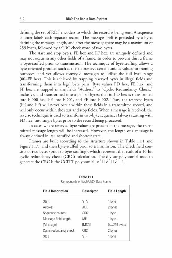
defining the set of RDS encoders to which the record is being sent. A sequencecounter labels each separate record. The message itself is preceded by a byte,defining the message length, and after the message there may be a maximum of255 bytes, followed by a CRC check word of two bytes.
The start and stop bytes, FE hex and FF hex, are uniquely defined andmay not occur in any other fields of a frame. In order to prevent this, a frameis byte-stuffed prior to transmission. The technique of byte-stuffing allows abyte-oriented protocol such as this to preserve certain unique values for framingpurposes, and yet allows conveyed messages to utilise the full byte range(00–FF hex). This is achieved by trapping reserved bytes in illegal fields andtransforming them into legal byte pairs. Byte values FD hex, FE hex, andFF hex are trapped in the fields “Address” to “Cyclic Redundancy Check,”inclusive, and transformed into a pair of bytes; that is, FD hex is transformedinto FD00 hex, FE into FD01, and FF into FD02. Thus, the reserved bytes(FE and FF) will never occur within these fields in a transmitted record, andwill only occur within the start and stop fields. When a message is received, thereverse technique is used to transform two-byte sequences (always starting withFD hex) into single bytes prior to the record being processed.
In cases where reserved byte values are present in the message, the trans-mitted message length will be increased. However, the length of a message isalways defined in its unstuffed and shortest state.
Frames are built according to the structure shown in Table 11.1 andFigure 11.5, and then byte-stuffed prior to transmission. The check field con-sists of two bytes (prior to byte-stuffing), which represent the result of a 16-bitcyclic redundancy check (CRC) calculation. The divisor polynomial used togenerate the CRC is the CCITT polynomial, x16 + x12 + x5 + 1.
212 RDS: The Radio Data System
Table 11.1Components of Each UECP Data Frame
Field Description Descriptor Field Length
Start STA 1 byte
Address ADD 2 bytes
Sequence counter SQC 1 byte
Message field length MFL 1 byte
[Message] [MSG] 0…255 bytes
Cyclic redundancy check CRC 2 bytes
Stop STP 1 byte
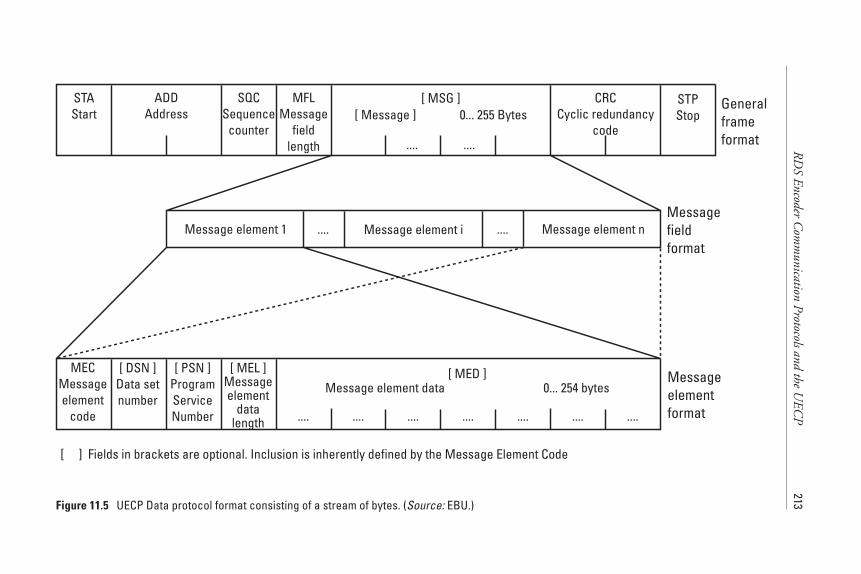
RD
SEncoder
Com
munication
Protocolsandthe
UEC
P213
STAStart
ADDAddress
SQCSequence
counter
MFLMessage
fieldlength
[ MSG ][ Message ] 0... 255 Bytes
CRCCyclic redundancy
code
STPStop
Generalframeformat
Message element 1 Message element i Message element n........Messagefieldformat
Messageelementformat
.... ....
MECMessageelement
code
[ DSN ]Data setnumber
[ PSN ]ProgramServiceNumber
[ MEL ]Messageelement
datalength
[ MED ]Message element data 0... 254 bytes
.... .... .... .... .... .... ....
[ ] Fields in brackets are optional. Inclusion is inherently defined by the Message Element Code
Figure 11.5 UECP Data protocol format consisting of a stream of bytes. (Source: EBU.)
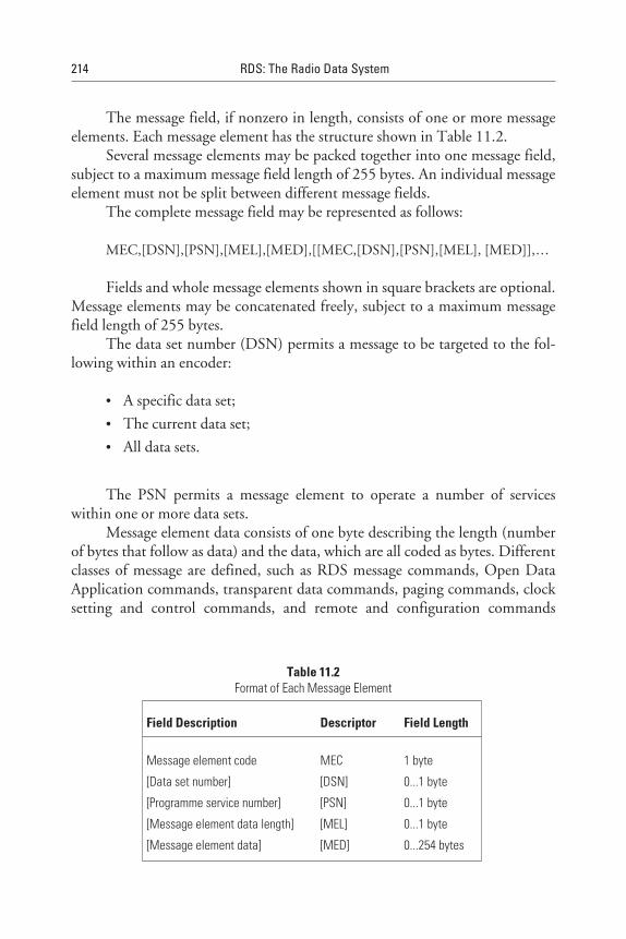
The message field, if nonzero in length, consists of one or more messageelements. Each message element has the structure shown in Table 11.2.
Several message elements may be packed together into one message field,subject to a maximum message field length of 255 bytes. An individual messageelement must not be split between different message fields.
The complete message field may be represented as follows:
MEC,[DSN],[PSN],[MEL],[MED],[[MEC,[DSN],[PSN],[MEL], [MED]],…
Fields and whole message elements shown in square brackets are optional.Message elements may be concatenated freely, subject to a maximum messagefield length of 255 bytes.
The data set number (DSN) permits a message to be targeted to the fol-lowing within an encoder:
• A specific data set;
• The current data set;
• All data sets.
The PSN permits a message element to operate a number of serviceswithin one or more data sets.
Message element data consists of one byte describing the length (numberof bytes that follow as data) and the data, which are all coded as bytes. Differentclasses of message are defined, such as RDS message commands, Open DataApplication commands, transparent data commands, paging commands, clocksetting and control commands, and remote and configuration commands
214 RDS: The Radio Data System
Table 11.2Format of Each Message Element
Field Description Descriptor Field Length
Message element code
[Data set number]
[Programme service number]
[Message element data length]
[Message element data]
MEC
[DSN]
[PSN]
[MEL]
[MED]
1 byte
0...1 byte
0...1 byte
0...1 byte
0...254 bytes
(RDS adjustment and control, ARI adjustment and control, control and setupcommands, bidirectional commands, and specific message commands).
Remote and configuration commands make it possible to control thevarious functionality options of RDS encoders, or permit request messages tobe given from the RDS encoders in the case of a bidirectional transmissionmode.
RDS message commands (for more details, see Appendix L) make it pos-sible to communicate all the RDS features that have to be processed by an RDSencoder.
The data is transmitted to the RDS encoder using the specified commandstructure and stored in memory according to the encoder software model. TheRDS encoder must also be told about the types of groups to be transmitted andabout the appropriate transmission rate for every transmitted group type. Thisis achieved with the group sequence command, which is treated by the encoderlike a group enable command. When a specific group is encountered in thesequence, data relating to that type is transmitted, if available. If no data for aspecific group type is received, then the group type is not generated and thenext group type in the sequence is used instead. With this method, the desiredrepetition rate for every group type is implicitly defined in a very flexible wayfor the broadcaster or service operator.
References
[1] EBU Universal Encoder Communications Protocol UECP, Version 5.1, European Broad-casting Union, 17A Ancienne Route, CH-1218 Geneva, Switzerland, Aug. 1997.
[2] CEN ENV 12313-1, Traffic and Traveller Information (TTI)-TTI Messages via TrafficMessage Coding, Part 1, Coding Protocol for Radio Data System-Traffic MessageChannel (RDS-TMC) using ALERT-C, European Committee for Standardisation(CEN), 36 rue de Stassart, B-1050 Brussels.
RDS Encoder Communication Protocols and the UECP 215
12RDS Demodulators and Decoders
12.1 Introduction
In this chapter, the functionality of a radio data decoder and the microcom-puter that controls the PLL tuner is explained. Existing ICs from variousmanufacturers for the RDS decoder/microprocessor (MCU) are mentioned.Then, the implementation of RDS in the three main categories of consumerreceivers—that is, car radios, home hi-fi, and portable radios—is discussed.Some known plug-in cards with an RDS radio for PCs are briefly presented,and the chapter closes with a section about professional software RDS datamonitors and data analysers for PCs and laptops in particular.
12.2 General Principles
12.2.1 RDS Demodulator/Decoder Technique and Functionality
Figure 12.1 shows the radio data demodulator/decoder in relation to the otherparts of a VHF/FM receiver equipped to use the Radio Data System. Thedecoder accepts the multiplex signal from the output of the FM discriminatoras its input, and feeds its output to a microprocessor. This microprocessordrives a display, controls the tuning of the receiver, and also performs some ofthe later stages of decoding the radio data signal. Microprocessor systems are,of course, most commonly incorporated in many of the more sophisticatedmodern receivers, employing frequency synthesised tuning (PLL) to controlthese tuning functions and the presets chosen by the user. The RDS decoder
217
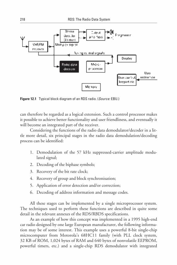
can therefore be regarded as a logical extension. Such a control processor makesit possible to achieve better functionality and user friendliness, and eventually itwill become an integrated part of the receiver.
Considering the functions of the radio data demodulator/decoder in a lit-tle more detail, six principal stages in the radio data demodulation/decodingprocess can be identified:
1. Demodulation of the 57 kHz suppressed-carrier amplitude modu-lated signal;
2. Decoding of the biphase symbols;
3. Recovery of the bit rate clock;
4. Recovery of group and block synchronisation;
5. Application of error detection and/or correction;
6. Decoding of address information and message codes.
All these stages can be implemented by a single microprocessor system.The techniques used to perform these functions are described in quite somedetail in the relevant annexes of the RDS/RBDS specifications.
As an example of how this concept was implemented in a 1995 high-endcar radio designed by one large European manufacturer, the following informa-tion may be of some interest. This example uses a powerful 8-bit single-chipmicrocomputer from Motorola’s 68HC11 family (with PLL clock system,32 KB of ROM, 1,024 bytes of RAM and 640 bytes of nonvolatile EEPROM,powerful timers, etc.) and a single-chip RDS demodulator with integrated
218 RDS: The Radio Data System
Figure 12.1 Typical block diagram of an RDS radio. (Source: EBU.)
57 kHz bandpass from either Philips or SGS/Thomson to obtain and processthe continuous synchronous data stream and the clock frequency of 1.1875 kHz(57 kHz/48). The relatively high power of the microprocessor is necessarybecause, apart from the RDS functions, it must control the PLL tuning system,the display of a car radio, the functional keys of the radio, the sophisticatedman/machine interface, the digitally controlled audio processor, the cassetteplayer, the remote controlled CD changer, the traffic announcement recordingsystem, the clock, and so on. Nearly all these operations must be done in realtime. Multitasking capability is therefore necessary for the different logicaldevices, because some devices must run simultaneously.
Every 842 µs (1000000/1187.5), the microprocessor will receive a newbit from the continuous RDS data stream delivered by the RDS demodulatorchip, load it into a 26-bit software shift register, and process the RDS data in a26-bit sequence. However, this is only true if the data stream is trulysynchronous; that is, the position of each bit in the data stream can be clearlyinterpreted. Loss of only one bit means that the microprocessor is getting asyn-chronous data. In that case, a more time-consuming task needs to be done toobtain block and group synchronisation.
To acquire group and block synchronisation at the receiver (for example,when the receiver is first switched on, or tuning to a new station, or after a pro-longed signal fade), the syndrome (see Appendix B) must be calculated for eachreceived 26-bit sequence. That is, on every data clock pulse, the syndrome ofthe currently stored 26-bit sequence (with the most recently received data bit atone end and the bit received 26 clock pulses ago at the other) is calculated onevery clock pulse. Then, with every new incoming bit (842 µs), a completemultiplication with the H-matrix (see Appendix B) has to be performed withall the 26 bits in the shift register. As a result, the 10-bit syndrome will beobtained. It must then be compared with the six known syndromes of thespecified offsets A (block 1), B (block 2), C (block 3 for group type A), C’(block 3 for group type B), D (block 4), and E (occurs only with RBDSand detects MMBS data blocks in multiples of 4 in the RDS data stream). If amatch occurs with a consecutive syndrome, 26 bits later (26 × 842 µs) after 22msec, then the microprocessor is synchronised with the data stream. RDS syn-chronisation thus occurs when two consecutive RDS blocks in series have beendetected.
If RDS reception quality is poor, this task requires a lot of processingpower; but if the reception is good, the decoding task is, of course, muchshorter. With mobile data reception, the RDS data stream can be full of errors,and a temporary 50% error rate is not uncommon. This is usually caused by thelow RDS injection level used by the broadcaster (±1.2 kHz in some criticalcases, while ±2.0 kHz is typical for the large majority of RDS implementations).
RDS Demodulators and Decoders 219
Another cause can be the simultaneous use of the ARI system (see also Appen-dix C, giving more detail about RDS data reception reliability). However, sincethe sequence of the syndromes is known, the decoding process can work asa “flywheel” mechanism, which is separately explained below. If an unknownsyndrome is detected, the respective block is bad; but if block 2 is bad, thewhole data group may be unusable unless error correction is used. However,the latter has to be used with caution because before it can be applied, the typeof error has to be identified before it can attempt any corrections—and eventhen it can generate an error, which is less problematic for data used for displayonly (e.g., PS and RT).
It is very important to detect loss of synchronisation as soon as possible.One possibility is to check the syndrome continuously for acquisition of syn-chronisation. However, errors in the channel will make it difficult to continu-ously receive the expected syndromes, and therefore the decision must be basedon the information from several blocks (e.g., up to 50 blocks). Another possi-bility is to check the number of errors in each block and base the decision onthe number of errors in 50 blocks.
One possibility for detecting block synchronisation slips of one bit is touse the PI code, which does not usually change on any given transmission. Ifthe known PI code is received correctly but is found to be shifted one bit to theright or to the left, then a one-bit clock slip is detected. The decoder can thenimmediately correct the clock slip.
12.2.2 Principles of the RDS Block Synchronisation System
The flywheel mechanism, used as a block synchronisation system in RDS, mayperhaps be more easily understood with the aid of the simple mechanical anal-ogy [1]. To develop that analogy, we first consider a conventional block syn-chronisation system, as illustrated in Figure 12.2(a). Here, the boundaries ofblocks are marked by fixed block synchronisation words.
If we represent the received data stream as an endless belt, then theseblock synchronisation words may be represented as fixed markers on the belt, asshown. In the decoder, we must have a counter that is clocked at the bit-rateand that modulo the block-size. This counter may be represented as a slottedroller whose circumference is equal to the distance between the markers on thebelt. It is easy to see that to synchronise the roller with the belt, all that is neces-sary is to allow the roller to slip until the slot meshes with one of the fixedmarkers. Once synchronised, the roller and the belt will remain in synchro-nism, even if some of the markers are damaged or missing. This illustrates theblock-synchronisation flywheel system that is needed to enable the decoder to
220 RDS: The Radio Data System

RD
SD
emodulatorsand
Decoders
221
One block
Information bits SS
Sync words
One block
Information bits Check bits andoffset word
Rigid cylinder with a slotSoft wax cylinder
Data streamData stream
Data stream
Characteristic
pattern
(syndrome)
Codewordand offset D
Codewordand offset C
Codewordand offset B
Codewordand offset A
Codewordand offset D
Fixed markers
(a)
(c)
(b)
(a) Conventional system(b) Self-synchronization code
[1] Cyclic code, regular pattern, no sync information[2] Modified cyclic code, irregular pattern,
sync information obtained(c) Group synchronization
[1] [2]
Figure 12.2 Mechanical analogies of the block synchronisation system. (Source: BBC/EBU.)

remain locked in synchronisation with the received data stream, especiallywhen the latter is heavily corrupted with errors.
The disadvantages of a conventional block synchronisation system arealso apparent from this analogy: Space must be allocated in the data stream forthe markers, and these markers have to be clearly recognisable amongst theother data in the stream. Although these difficulties can be overcome (manydata systems work this way), the particular requirements of radio data within anFM multiplex, favour a novel approach [2].
Using a similar mechanical analogy, the underlying principle of this novelblock synchronisation system is illustrated in Figure 12.2(b). Here, the receivedcode words are represented as a rack with irregular teeth, and the decoder in thereceiver is represented as a soft-wax roller, which is capable of taking an impres-sion of the rack as it is rolled along. Again, the circumference of the rotatingroller is chosen to be equal to the distance between block (code word) bounda-ries on the rack. If the roller is rolled along the rack, starting at the beginningof the code word and ending at the end, then the resulting impression on thecircumference of the cylinder will contain all the information about that codeword. If the wax roller is subjected to further processing, analogous to theprocess in the error-protecting decoder, it is possible to see that the initialimpression on the roller could be converted to one that depends not upon thetransmitted message but only on the errors in the received code word. This pat-tern is analogous to the characteristic pattern or “syndrome” of an error-protecting decoder (see Appendix B).
If the movement of the roller is started and ended away from code wordboundaries, the resulting first impression on the roller would comprise parts oftwo separate code words. It is a remarkable fundamental property of a conven-tional cyclic, or shortened cyclic code, that the characteristic pattern (syn-drome) obtained by applying the error-checking process to such a mixture will,with high probability, be the same as for that obtained from one complete validcode word. In our analogy, we represent this case by the cyclically symmetricalpattern shown on the lower left-hand roller in Figure 12.2(b). Clearly, such apattern would not provide reliable block synchronisation information.
If, however, the cyclic nature of the code is destroyed, which is done inRDS by adding binary offset words to each transmitted check word, an asym-metric pattern will result, as illustrated by analogy with the pattern on the rollerin the bottom right of Figure 12.2(b). It is easy to see that such an irregular pat-tern can provide the necessary synchronisation information.
Block synchronisation is thus first obtained by trial and error, processingeach 26-bit sequence until the expected characteristic pattern results. With a
222 RDS: The Radio Data System
high probability, this will occur only when the processed 26-bit sequence com-prises one complete code word.
Different offset words added to each check word will yield differentcharacteristic patterns, and in RDS, four different offsets are used in each datagroup to identify the four blocks that form the group. This may be illustratedby developing the mechanical analogy, as shown in Figure 12.2(c). There, thecircumference of the wax roller has been increased by a factor of four, comparedwith that of Figure 12.2(b). Then, after it has been rolled along the section ofthe rack that represents the four blocks comprising a group, four different char-acteristic patterns will result around the circumference of the roller, as illus-trated by the different shades in that figure.
It should be noted that once one characteristic pattern has been found,the rest follows in cycle sequence. Thus, all the necessary group synchronisationinformation can be obtained within one block length, and this provides rapiddata acquisition.
Here is a short summary of this novel group and block synchronisationsystem. The beginnings and ends of the data blocks may be recognised in thereceiver/decoder by using the fact that the error-checking decoder will, with ahigh level of confidence, detect block synchronisation slip. The blocks withineach group are identified by carefully chosen 10-bit binary words (offsets) thatare added (modulo two) to the CRC check words such that offset word A isadded to block 1 in each group, offset word B is added to block 2, and so on.For more details, see Appendix B.
12.2.3 Error Correction and/or Detection
The error-protecting code that is used in RDS is an optimal single-burst error-correcting code and is capable of correcting any single burst of errors that spansfive bits or less. However, the use of the full error-correcting capability greatlyincreases the undetected error rate and thus also reduces the reliability of theblock synchronisation system. In most experimental decoders used for RDSfield trials, the following restrictions were observed when performing errorcorrection:
1. When the decoder is searching for block and group synchronisation(e.g., on switch-on or on retuning the receiver to a different station),the error-correction capability of the code is not used at all. Thisallows the full error-detecting capability of the code to be used todetect synchronisation slip.
RDS Demodulators and Decoders 223

2. When the decoder has acquired group and block synchronisation,the error-correction system should be enabled, but should berestricted by attempting to correct bursts of errors spanning one ortwo bits. The encoder should attempt to detect (and then discard)blocks with longer bursts of errors.
12.3 RDS Integrated Circuits and Chip Sets
The major manufacturers of RDS components, having made them by the mil-lions, are Philips Semiconductors and SGS-Thomson. The references for theircurrent circuits are as follows:
• Philips: SAA6579T (demodulator and integrated 57 kHz bandpass fil-ter). SAA6588 is an RDS preprocessor which, in addition to thedemodulator and integrated 57 kHz bandpass filter, includes improve-ments resulting in more reliable data reception during weak signalinput. Also, it performs RDS block detection, error detection/correc-tion, synchronisation, flywheel, bit slip correction, and data processingcontrol. CCR520S, CCR526S, and CCR610S are RDS-specific com-plete chip sets for high-end RDS/EON car radios that include theMCU with RDS-specific processing software. CCR991 and CCR922are RDS-specific 8-bit MCUs with software for RDS/RBDS andMBS/MMBS (only CCR922) preprocessing.
• SGS-Thomson: TDA7330B or TDA7330BD, TDA7331B, orTDA7331BD, and TDA7479 (all these are single-chip demodulatorswith an integrated 57 kHz bandpass filter). TDA7332 orTDA73312D are 57 kHz bandpass filters. ST7285A5 is an 8-bitRDS-specific MCU (user ROM of 48 KB, data RAM of 3 KB) with anintegrated RDS demodulator and a 57 kHz bandpass filter.
Other manufacturers in the years since 1987 were Bosch-Blaupunkt (inassociation with Texas Instruments), Sanyo (LC7070, LC72721, andLC72720N—single chips with filter and demodulator), Tokyo Cosmos, NEC(uPC2539GS—filter and demodulator), Siemens, and Rohm (BU1920F—fil-ter and demodulator).
Prices have now become very competitive, and are generally at levelswhere the RDS functionality no longer adds significantly to the receiver price,except at the low end of the market.
224 RDS: The Radio Data System

12.4 Consumer Receivers
12.4.1 Car Radios
There are about 50 manufacturers in the European market with more than400 different models, from high-end models down to the midrange and evendown to low-end models, but the U.S. market still lags behind. We haveto distinguish between first- and second-generation RDS; that is, in the firstcase only PI, PS name, AF, TP and TA flag features are supported, while inthe second case, there is also EON (TA, AF, and PTY), PTY, CT, MS andeven RT).
In the early stages of certain new products, especially from less well-known companies, some of the basic RDS features could have been left out andsome malfunctioning of the RDS option was not uncommon. At a later stage ofthese products, improvements have been achieved, especially if the BBC’s serv-ices for testing receivers were used.
Those manufacturers that have been in this market now for many yearsalready have achieved, in the majority of cases, very fine products at verycompetitive prices, but to this category belong only, perhaps, a quarter of the50 manufacturers. Fortunately, they have also made the largest number ofthe existing RDS radios sold.
In the United States, Delco, Denon, and Pioneer are among thosecompanies that lead the RDS car radio market. They collaborate closely withthe American carmakers to provide OEM products and in 1997, Ford, GeneralMotors, and Toyota have all announced that they will start to offer Americancars equipped with RDS radios (see Figure 12.3).
European carmakers have also started to offer their cars with RDS radiosto the U.S. market.
12.4.2 Home Hi-Fi
There are now hundreds of models from about 25 different manufacturers onthe European market. The U.S. market still lags behind. Prices range from veryhigh to reasonably low. All support PS, some support AF, and several of themsupport RT, PTY, and CT. In this kind of product, the price of the RDS com-ponent is not significant anymore; therefore, we expect that in the future mostof these models will be equipped for RDS.
12.4.3 Portable Radios
There is still some reluctance toward this kind of product on the side ofthe manufacturers, while broadcasters believe that, especially in this area, RDS
RDS Demodulators and Decoders 225
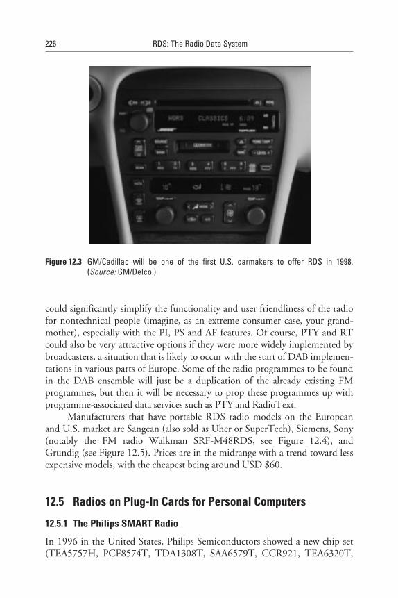
could significantly simplify the functionality and user friendliness of the radiofor nontechnical people (imagine, as an extreme consumer case, your grand-mother), especially with the PI, PS and AF features. Of course, PTY and RTcould also be very attractive options if they were more widely implemented bybroadcasters, a situation that is likely to occur with the start of DAB implemen-tations in various parts of Europe. Some of the radio programmes to be foundin the DAB ensemble will just be a duplication of the already existing FMprogrammes, but then it will be necessary to prop these programmes up withprogramme-associated data services such as PTY and RadioText.
Manufacturers that have portable RDS radio models on the Europeanand U.S. market are Sangean (also sold as Uher or SuperTech), Siemens, Sony(notably the FM radio Walkman SRF-M48RDS, see Figure 12.4), andGrundig (see Figure 12.5). Prices are in the midrange with a trend toward lessexpensive models, with the cheapest being around USD $60.
12.5 Radios on Plug-In Cards for Personal Computers
12.5.1 The Philips SMART Radio
In 1996 in the United States, Philips Semiconductors showed a new chip set(TEA5757H, PCF8574T, TDA1308T, SAA6579T, CCR921, TEA6320T,
226 RDS: The Radio Data System
Figure 12.3 GM/Cadillac will be one of the first U.S. carmakers to offer RDS in 1998.(Source: GM/Delco.)
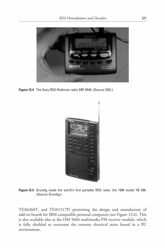
TEA6360T, and TDA1517P) permitting the design and manufacture ofadd-on boards for IBM-compatible personal computers (see Figure 12.6). Thisis also available also as the OM 5604 multimedia FM receiver module, whichis fully shielded to overcome the extreme electrical noise found in a PCenvironment.
RDS Demodulators and Decoders 227
Figure 12.4 The Sony RDS Walkman radio SRF-M48. (Source: EBU.)
Figure 12.5 Grundig made the world’s first portable RDS radio: the 1994 model YB 500.(Source: Grundig.)
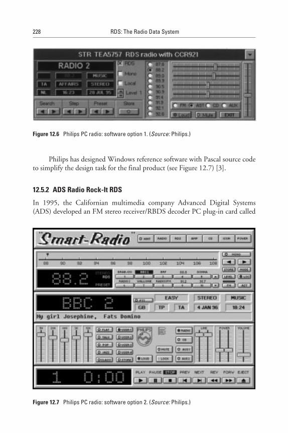
Philips has designed Windows reference software with Pascal source codeto simplify the design task for the final product (see Figure 12.7) [3].
12.5.2 ADS Radio Rock-It RDS
In 1995, the Californian multimedia company Advanced Digital Systems(ADS) developed an FM stereo receiver/RBDS decoder PC plug-in card called
228 RDS: The Radio Data System
Figure 12.6 Philips PC radio: software option 1. (Source: Philips.)
Figure 12.7 Philips PC radio: software option 2. (Source: Philips.)
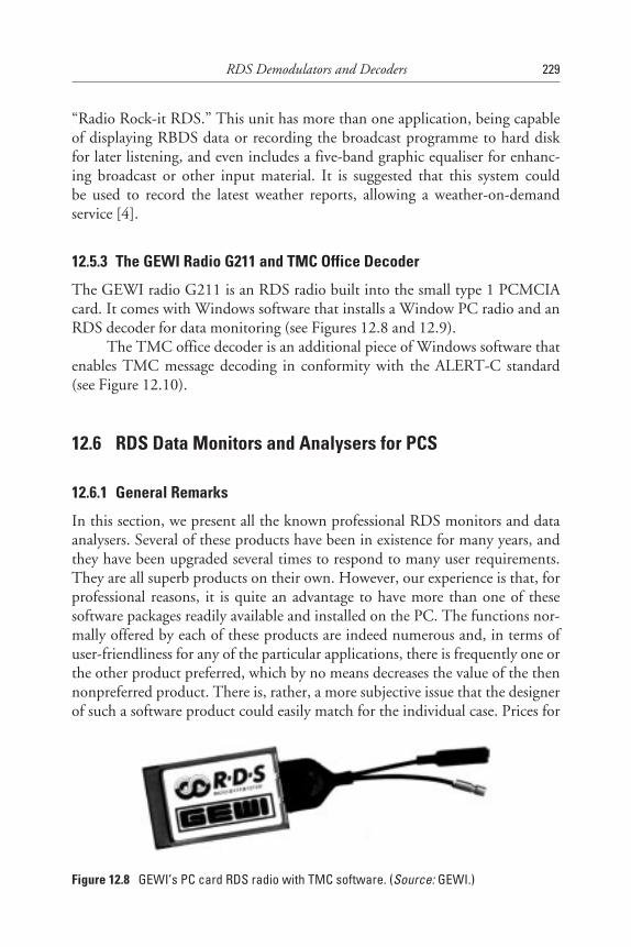
“Radio Rock-it RDS.” This unit has more than one application, being capableof displaying RBDS data or recording the broadcast programme to hard diskfor later listening, and even includes a five-band graphic equaliser for enhanc-ing broadcast or other input material. It is suggested that this system couldbe used to record the latest weather reports, allowing a weather-on-demandservice [4].
12.5.3 The GEWI Radio G211 and TMC Office Decoder
The GEWI radio G211 is an RDS radio built into the small type 1 PCMCIAcard. It comes with Windows software that installs a Window PC radio and anRDS decoder for data monitoring (see Figures 12.8 and 12.9).
The TMC office decoder is an additional piece of Windows software thatenables TMC message decoding in conformity with the ALERT-C standard(see Figure 12.10).
12.6 RDS Data Monitors and Analysers for PCS
12.6.1 General Remarks
In this section, we present all the known professional RDS monitors and dataanalysers. Several of these products have been in existence for many years, andthey have been upgraded several times to respond to many user requirements.They are all superb products on their own. However, our experience is that, forprofessional reasons, it is quite an advantage to have more than one of thesesoftware packages readily available and installed on the PC. The functions nor-mally offered by each of these products are indeed numerous and, in terms ofuser-friendliness for any of the particular applications, there is frequently one orthe other product preferred, which by no means decreases the value of the thennonpreferred product. There is, rather, a more subjective issue that the designerof such a software product could easily match for the individual case. Prices for
RDS Demodulators and Decoders 229
Figure 12.8 GEWI’s PC card RDS radio with TMC software. (Source: GEWI.)
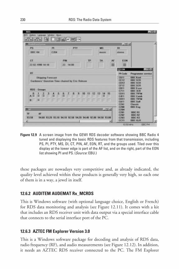
these packages are nowadays very competitive and, as already indicated, thequality level achieved within these products is generally very high, so each oneof them is in a way, a jewel in itself.
12.6.2 AUDITEM AUDEMAT Rx_MCRDS
This is Windows software (with optional language choice, English or French)for RDS data monitoring and analysis (see Figure 12.11). It comes with a kitthat includes an RDS receiver unit with data output via a special interface cablethat connects to the serial interface port of the PC.
12.6.3 AZTEC FM Explorer Version 3.0
This is a Windows software package for decoding and analysis of RDS data,radio frequency (RF), and audio measurements (see Figure 12.12). In addition,it needs an AZTEC RDS receiver connected to the PC. The FM Explorer
230 RDS: The Radio Data System
Figure 12.9 A screen image from the GEWI RDS decoder software showing BBC Radio 4tuned and displaying the basic RDS features from that transmission, includingPS, PI, PTY, MS, DI, CT, PIN, AF, EON, RT, and the groups used. Tiled over thisdisplay at the lower edge is part of the AF list, and on the right, part of the EONlist showing PI and PS. (Source: EBU.)
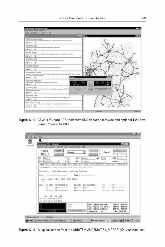
RDS Demodulators and Decoders 231
Figure 12.10 GEWI’s PC card RDS radio with RDS decoder software and optional TMC soft-ware. (Source: GEWI.)
Figure 12.11 A typical screen from the AUDITEM AUDEMAT Rx_MCRDS. (Source: Auditem.)

combines in one product a multitude of RDS functions with measurement andstatistical analysis capabilities, including that of the RF level and the modula-tion characteristics.
12.6.4 The RDS Software Decoder Version 2.0 from Franken-Team
The RDS Software Decoder is a DOS application for RDS reception thatrequires an RDS receiver to be slightly modified; that is, the digital signals RDSDATA and RDS CLOCK need to be wired from the RDS demodulator chip toa suitable socket (e.g., a 3.5-mm stereo phone jack). An interface cable, whichincludes a buffer for decoupling, is provided. The decoder is suitable for analys-ing all RDS/RBDS features as specified in the latest versions of both standards(see Figure 12.13). An RDS event recorder makes it possible to storedynamic events such as change of PI or RT. The logic analyser makes it possibleto record RDS data with various trigger modes for later analysis. Up to2,100 groups of RDS data, including check bits (three minutes), can berecorded.
232 RDS: The Radio Data System
Figure 12.12 An FM band-scan made with AZTEC’s analysis and decoding software.(Source: AZTEC.)
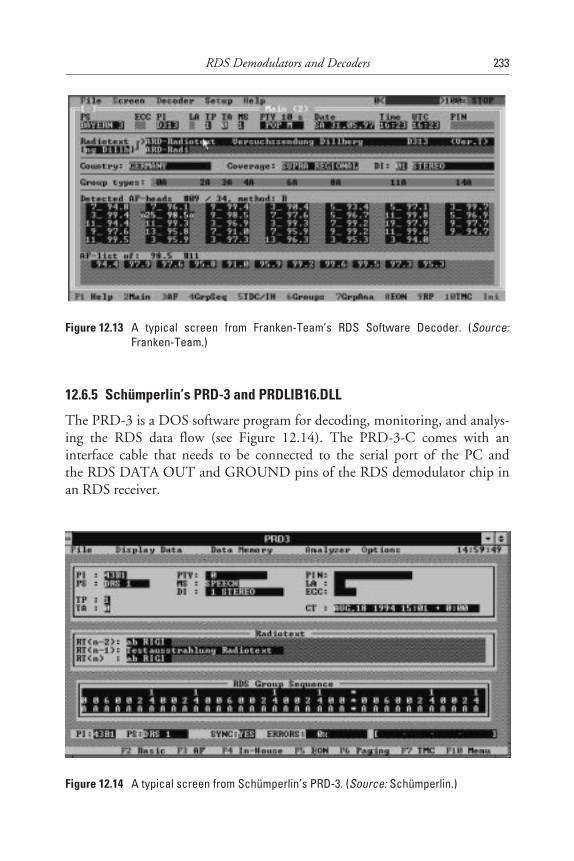
12.6.5 Schümperlin’s PRD-3 and PRDLIB16.DLL
The PRD-3 is a DOS software program for decoding, monitoring, and analys-ing the RDS data flow (see Figure 12.14). The PRD-3-C comes with aninterface cable that needs to be connected to the serial port of the PC andthe RDS DATA OUT and GROUND pins of the RDS demodulator chip inan RDS receiver.
RDS Demodulators and Decoders 233
Figure 12.13 A typical screen from Franken-Team’s RDS Software Decoder. (Source:Franken-Team.)
Figure 12.14 A typical screen from Schümperlin’s PRD-3. (Source: Schümperlin.)
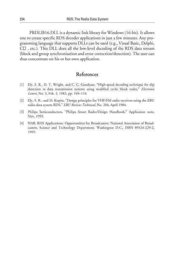
PRDLIB16.DLL is a dynamic link library for Windows (16-bit). It allowsone to create specific RDS decoder applications in just a few minutes. Any pro-gramming language that supports DLLs can be used (e.g., Visual Basic, Delphi,C++, etc.). This DLL does all the low-level decoding of the RDS data stream(block and group synchronisation and error correction/detection). The user canthus concentrate on his or her own application.
References
[1] Ely, S. R., D. T. Wright, and C. C. Goodyear, “High-speed decoding technique for slipdetection in data transmission systems using modified cyclic block codes,” ElectronicLetters, No. 3, Feb. 3, 1983, pp. 109–110.
[2] Ely, S. R., and D. Kopitz, “Design principles for VHF/FM radio receivers using the EBUradio-data system RDS,” EBU Review-Technical, No. 204, April 1984.
[3] Philips Semiconductors, “Philips Smart Radio/Design Handbook,” Application note,Nov. 1995.
[4] NAB, RDS Applications: Opportunities for Broadcasters, National Association of Broad-casters, Science and Technology Department, Washington D.C., ISBN 89324-229-2,1995.
234 RDS: The Radio Data System
13Outlook: RDS and Other Broadcast DataSystems for Radio
13.1 Introduction
This chapter reviews other radio data systems that are already used for datatransmissions in the allocated frequency bands for terrestrial or satellite radio.The possibilities offered by these systems are compared with RDS wherever thisis possible. A forecast is made about the market impact from the present pointof view for all these systems. The following systems are being reviewed: AMDSand Digital Radio Mondial, the latter for AM broadcasting replacement by anew digital broadcast system; the high-speed data systems DARC/SWIFT,HSDS, and STIC for FM broadcasting; Digital Radio (Eureka 147-DAB),ADR, DSR, DVB, and WorldSpace.
13.2 LF, MF, and HF Broadcasting
13.2.1 AM Data System
Tests in the 1980s showed that low-rate data could be carried by LF and MFtransmissions. For many years, the BBC 198 kHz transmitter has used phasemodulation of the carrier to achieve 50 bps; however, tests on “Hochschule fürVerkehrswesen Dresden” showed that it was possible to add a data stream of200 bps using a phase modulation of ±15° to an AM transmitter, with minimaldegradation of the received audio quality. Since 1986, extensive field trials have
235
been conducted to find an appropriate baseband coding to match the bit errorconditions of AM channels in LF, MF, and HF broadcast bands.
The AM Data System, or AMDS, as it has come to be known, owes itsorigin to these trials. In 1994, the AMDS specification was expanded with thehelp of the EBU, but it concerns only the baseband coding for data broadcast-ing on LF, MF, and HF. Use was made of the experience gained by thosebroadcasters in Germany, France, the Netherlands, and the United Kingdom.They had conducted field trials with phase modulation as the modulationmethod, permitting a total bit rate of 200 bps. For example, in Germany, anational working party had already attempted to draft the specification, and theEBU made use of this to considerably widen its scope. In addition, in 1995,the ITU-R Working Party 10A prepared ITU-Recommendation BS.706-1 forAMDS. However, there are major problems with all the attempts made so farto get AMDS off the ground. One problem is that the modulation methodused is incompatible with single-sideband broadcasting (SSB), which could inprinciple be used more and more for HF broadcasting. In addition, AMDS isincompatible with AM stereo, used in the United States. For these two reasons,the system has gained little support so far, and there are practically no suitablereceivers apart from a few prototypes (mainly used for TMC, and DGPS fieldtrials on LF and MF in Germany).
For HF broadcasting where changing ionospheric propagation conditionsrequire broadcasters to use several HF bands during the course of a day, AMDS(as tested in these field trials) would definitely have been of some interest if SSBwere not around the corner. In 1996, other alternatives were still being studied;for example, in the United States in the context of RBDS, and in Hong Kongby ID logic involving several large HF broadcasters from Europe and NorthAmerica. Therefore, it is quite possible that a solution will soon present itselfthat overcomes the limitations that have so far hampered the success of an RDSfor AM broadcasting.
The AMDS features described in the EBU’s specification broadly followthe ideas of the RDS features, and many will be easily recognised, such as AF,DGPS, IH, RT, TDC, and TMC. Among the new features are additional tun-ing information (ATI), basic tuning and switching information (BTI), schedul-ing information (SI and SIS), and time information (UTC). SI and SIS pick upthe idea of the EON feature of RDS and provide scheduling data for receiversto be stored in their memory. This feature is designed for HF applications,where programme breaks may occur in the order of every 15 minutes to 1 hour,resulting in many frequency and programme changes.
In 1996, there were still a number of test transmissions in LF, MF, andHF from European-based transmitters. One LF transmitter at 153 kHz forDeutschlandradio in Germany was providing TMC. Two MF transmitters in
236 RDS: The Radio Data System
Norway were providing DGPS to cover coastal waters, and one transmitterin Germany at 756 kHz was also providing DGPS. Receivable over a wide areawere the HF transmissions from Deutsche Welle in Germany, at 6,140 kHzand 13,780 kHz in German and at several other frequencies carrying foreignlanguages.
13.2.2 New Developments Using Digital Modulation
Looking into the future of LF, MF, and HF broadcasting, it is more and morelikely that analogue AM broadcasting will soon be replaced in these frequencybands with new radio systems using digital AM. These all will, of course, con-tain a radio data channel with features similar to those used in RDS.
At the time of this writing, the following steps in this development hadalready been completed [1]:
• October 1994: ITU Study Group 10 issues a report about digital AM;
• November 1994: First tests on MF in Berlin by Deutsche Telekomusing SKYWAVE 2000 by Thomcast;
• February 1995: A European working party is formed to find a consoli-dated approach;
• June 1996: EUREKA accepts the new project EU 1559 NarrowbandDigital Broadcasting (NADIB). Consortium members includedDeutsche Welle, Radio France International, Telefunken, Thomcast,Sony, Deutsche Telekom, Teracom, and the Fraunhofer Institute;
• December 1996: Start of one-hour daily test transmissions on shortwaves from Jülich (Germany);
• April 1997: Establishment of the new collaborative project DigitalRadio Mondial (DRM), led by Voice of America and aiming at thedevelopment of a digital short-wave broadcasting system that is resil-ient to fading, which characterises analogue shortwave broadcastingtoday.
13.3 FM Broadcasting
13.3.1 The Future of RDS
RDS will remain unchallenged in the market of FM broadcasting for manyyears to come, and today one can say with some confidence that no competitorto RDS is really on the horizon. The international scene for system standards
Outlook: RDS and Other Broadcast Data Systems for Radio 237
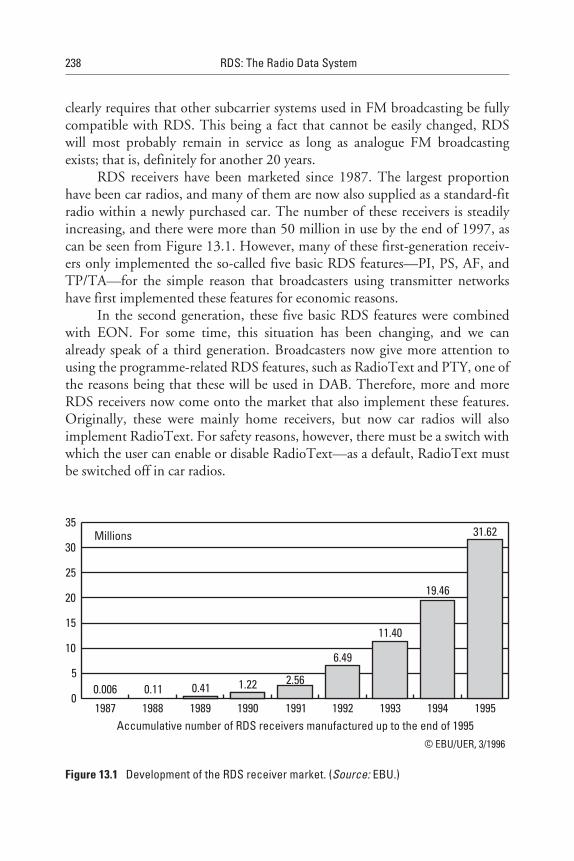
clearly requires that other subcarrier systems used in FM broadcasting be fullycompatible with RDS. This being a fact that cannot be easily changed, RDSwill most probably remain in service as long as analogue FM broadcastingexists; that is, definitely for another 20 years.
RDS receivers have been marketed since 1987. The largest proportionhave been car radios, and many of them are now also supplied as a standard-fitradio within a newly purchased car. The number of these receivers is steadilyincreasing, and there were more than 50 million in use by the end of 1997, ascan be seen from Figure 13.1. However, many of these first-generation receiv-ers only implemented the so-called five basic RDS features—PI, PS, AF, andTP/TA—for the simple reason that broadcasters using transmitter networkshave first implemented these features for economic reasons.
In the second generation, these five basic RDS features were combinedwith EON. For some time, this situation has been changing, and we canalready speak of a third generation. Broadcasters now give more attention tousing the programme-related RDS features, such as RadioText and PTY, one ofthe reasons being that these will be used in DAB. Therefore, more and moreRDS receivers now come onto the market that also implement these features.Originally, these were mainly home receivers, but now car radios will alsoimplement RadioText. For safety reasons, however, there must be a switch withwhich the user can enable or disable RadioText—as a default, RadioText mustbe switched off in car radios.
238 RDS: The Radio Data System
0
5
10
15
20
25
30
35
199519941993199219911990198919881987
31.62
19.46
11.40
6.49
2.561.220.410.110.006
Millions
© EBU/UER, 3/1996
Accumulative number of RDS receivers manufactured up to the end of 1995
Figure 13.1 Development of the RDS receiver market. (Source: EBU.)
The large majority of consumer electronic manufacturers around theworld support RDS technology. In Europe, prices for the RDS option are nowonly slightly higher than for a radio without RDS. There are already manymanufacturers that equip almost all their FM radio products for the Europeanmarket with an RDS module. Therefore, if the development continues with thesame speed as in the past, we should soon reach the state where almost all newradios are equipped for RDS performance.
13.3.2 High-Speed Data Systems
13.3.2.1 General ConsiderationsThe systems considered here use the frequency range above 61 kHz in the FMmultiplex, and only those that are compatible with RDS will be mentioned.These systems achieve a significantly higher data rate than RDS.
Generally speaking, FM subcarrier systems appear, under certain condi-tions, to have some adverse effects on the reception of the audio carried on theparent FM transmission. This is particularly true in the presence of multipathpropagation; that is in areas where the radio waves are bounced back byhigh-rise buildings or other obstacles, such as mountains. The significance andacceptability of these effects varies considerably, and depends on several factors:injection level of the subcarrier signal, its modulation system (where digital sys-tems are less damaging), the particular type of receiver (fixed, portable, or carradio) and the way it is designed, the nature of the wanted radio programme(i.e., whether there is frequently low-level audio as in classical music or whetherthere is a continuously high-level sound) and the propagation environment(most critical are mountainous regions and cities with high rise buildings).
The addition of FM subcarrier systems is permitted only if they use alltogether no more than 10% deviation of the total FM carrier deviation permit-ted, which is ±75 kHz. If several subcarriers are used, it may be necessaryto reduce the deviation for the main audio programme. Also, it is importantto examine whether a subcarrier system complies with ITU-R Recommenda-tions BS.412-7 and BS.450-2; that is, it has no adverse effect on the establishedprotection ratios used for frequency planning.
13.3.2.2 DARC/SWIFTData Radio Channel (DARC) was developed by NHK and was, up to the endof 1997, mainly used in Japan (16 kbps) and partly also the United States (bya company called Digital DJ), occupying a bandwidth of 35 kHz centredon 76 kHz. The DARC injection level changes with the level of the audio
Outlook: RDS and Other Broadcast Data Systems for Radio 239
programme modulation; that is, it is dynamic and depends precisely on thelevel of the stereo difference signal. The system characteristics are generallydescribed in ITU-R Recommendation BS.1194-1 [2, 3].
In Europe, the DARC system is getting increasingly popular for the intro-duction of special open or subscription data services, which will be broadcastedto specific user groups. DARC was extensively tested and further developed bythe Eureka 1197 Project “System for Wireless Infotainment and ForwardingTeledistribution” (SWIFT), which used the DARC modulation scheme (trans-mission layer 1 and 2) but a different baseband coding (transmission layer 3).This project started in 1994 and involved the telecommunications companiesof France, Germany, and Norway and the broadcast transmitter operator,Teracom in Sweden. The project has produced a European ETSI standard thatwas adopted in 1997 [4]. First implementations are foreseen in Austria, France,Germany, the Netherlands, Norway, Sweden, and Switzerland, beginningin 1998.
To achieve a data service range as large as that of the audio programme, ahigher data injection level is required (typically ±7.5 kHz) than the one used forRDS (typically ±2 kHz). Thus, when RDS and DARC are implemented, themaximum deviation of the audio programme has to be somewhat reduced toensure that the total deviation remains within the ±75 kHz maximumpermitted.
At the time of writing, the DARC system in Europe aimed at a nichemarket; that is, the provision of radio data channels to small portable datareceivers (e.g., made by Casio, Sharp, and Sony) and PCs, with the receiverbeing implemented on a PC card (PCMCIA) using Japanese ICs from Sanyo orOki. Use is also made of a conditional access technique with the key being elec-tronically provided through a receiver identification code, permitting the userto be charged for the services provided. Services to be provided could be elec-tronic newspapers, stock market and other financial data, an enhanced TMC,and the DGPS. Digital DJ (United States) started to launch similar services inthe major U.S. metropolitan areas (see Figure 13.2).
Since 1996, the DARC technology has been promoted by the DARCForum, which functions in a similar way to the RDS Forum, with some of themembers participating in both.
The DARC Forum holds the view that the DARC system is a flexible andtransparent data channel. It is an intermediate system that can be implementedin a short time in order to make the transition from RDS basic data services toadvanced digital radio (DAB) data services possible by using the existing FMnetwork infrastructure, which already provides excellent coverage everywhere.Thus, the DARC system can be easily implemented, providing a good coverage
240 RDS: The Radio Data System

area and a high availability for mobile reception at a fairly low cost. DARCcould also be considered to provide a good marketing test opportunity forfuture radio data broadcast services [5].
13.3.2.3 Other Subcarrier SystemsAnother system is the Seiko Telecommunication System (United States),HSDS, used on some transmitters in America and Europe. HSDS achieves19 kbps, occupying the 57–76 kHz range in the FM multiplex with the subcar-rier on 66.5 kHz.
A third system, so far of interest only in the United States, is calledMITRE Subcarrier Traffic Information Channel (STIC) centred on 72.2 kHz(with a net user data rate of 7.6 kbps) from the U.S. company, RadioDynamics.
In the United States since 1994, the NRSC High Speed Subcarrier Sub-committee has sought to evaluate the three systems with the view of achievingagreement on a voluntary U.S. standard that would recommend either one ofthese systems or a combination that incorporated all their recognised optimalfeatures after an agreed upon field evaluation under identical test conditions forthe three systems (DARC, HSDS and STIC). In March 1998, this objectivewas declared to have ended up in a deadlock due to the fact that the interestedparties (mainly the system proponents) could not agree upon a single solution.The results of the field tests, which revealed that all the three systems performedrelatively well, were submitted to ITU-R Study Group 10. This group decidedto incorporate the results into ITU-R Recommendation BS.1194-1, whichnow recommends all three systems.
Outlook: RDS and Other Broadcast Data Systems for Radio 241
Figure 13.2 The Digital DJ low-cost DARC receiver from Sharp is designed to deliver a newkind of subscriber radio data service in the United States, Europe, and Japan.(Source: EBU.)
13.4 Digital Radio DAB
13.4.1 Origins and Possible Evolution
The future is most probably set for DAB, which already is increasingly used onVHF and the L-band (1.5 GHz). DAB is a European standard of ETSI (firstpublished in 1994) [6] and a world standard recommended by the Interna-tional Telecommunications Union (ITU). The system has been developed overa period of some ten years (beginning in 1986) by the Eureka 147 Consortium,with the EBU coordinating the writing of the specification. DAB is alreadywidely implemented in large parts of Europe and Canada. Several othercountries in the world also experiment with this system. In early 1998, about150 million people were potentially able to receive DAB. However, receiverswere still expensive and therefore largely unavailable except for field trials.However, expectations in the WorldDAB Forum are high, and indicate thatthis is going to change in late 1998 [7, 8]. Most recently, some important tech-nological breakthroughs were achieved. A single chip receiver was developedjointly by Hitachi and Roke Manor, and a DABman (DAB version of aWalkman) was developed by Bosch. Clarion has developed a fully integratedone-box car receiver. In addition, a small British software company,RadioScape, has developed a full software DAB receiver that uses a standardIntel Pentium chip PC for decoding, rather than dedicated integrated circuitsspecifically designed for DAB. This opens the door to a wide range of multime-dia applications that could be implemented via software, downloadable to thereceiver; for example, a laptop computer being able to process the complete2.3 Mbps DAB multiplex in real time.
DAB has numerous advantages over VHF/FM broadcasting. It offers sig-nificantly better reception quality for both audio and data services; that is, itovercomes the adverse effects of multipath propagation, so badly experienced inVHF/FM broadcasting. DAB offers a high degree of ruggedness. In addition,DAB provides for a very high spectrum economy due to the single frequencynetwork technique and, further, a high flexibility for assembling, even dynami-cally, a number of different audio and data services to the service multiplex,called the “ensemble.” One ensemble would typically provide capacity for sixstereophonic audio programmes (each with a bit rate of 192 kbps), each havingits own programme-associated data channel PAD (32 kbps) and additionalcapacity for other radio data in both the fast information channel (FIC) and theauxiliary information channel (AIC) [9–11].
The choice for multiplexing the ensemble is so wide that in the extreme,all audio could be replaced by data, permitting one video channel with sound.
242 RDS: The Radio Data System
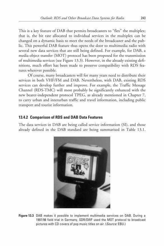
This is a key feature of DAB that permits broadcasters to “flex” the multiplex;that is, the bit rate allocated to individual services in the multiplex can bechanged on a dynamic basis to meet the needs of the broadcaster and the pub-lic. This powerful DAB feature thus opens the door to multimedia radio withseveral new data services that are still being defined. For example, for DAB, amedia object transfer (MOT) protocol has been proposed for the transmissionof multimedia services (see Figure 13.3). However, in the already existing defi-nitions, much effort has been made to preserve compatibility with RDS fea-tures wherever possible.
Of course, many broadcasters will for many years need to distribute theirservices in both VHF/FM and DAB. Nevertheless, with DAB, existing RDSservices can develop further and improve. For example, the Traffic MessageChannel (RDS-TMC) will most probably be significantly enhanced with thenew bearer-independent protocol TPEG, as already mentioned in Chapter 7,to carry urban and interurban traffic and travel information, including publictransport and tourist information.
13.4.2 Comparison of RDS and DAB Data Features
The data services in DAB are being called service information (SI), and thosealready defined in the DAB standard are being summarised in Table 13.1.
Outlook: RDS and Other Broadcast Data Systems for Radio 243
Figure 13.3 DAB makes it possible to implement multimedia services on DAB. During a1997/98 field trial in Germany, SDR/SWF used the MOT protocol to broadcastpictures with CD covers of pop music titles on air. (Source: EBU.)
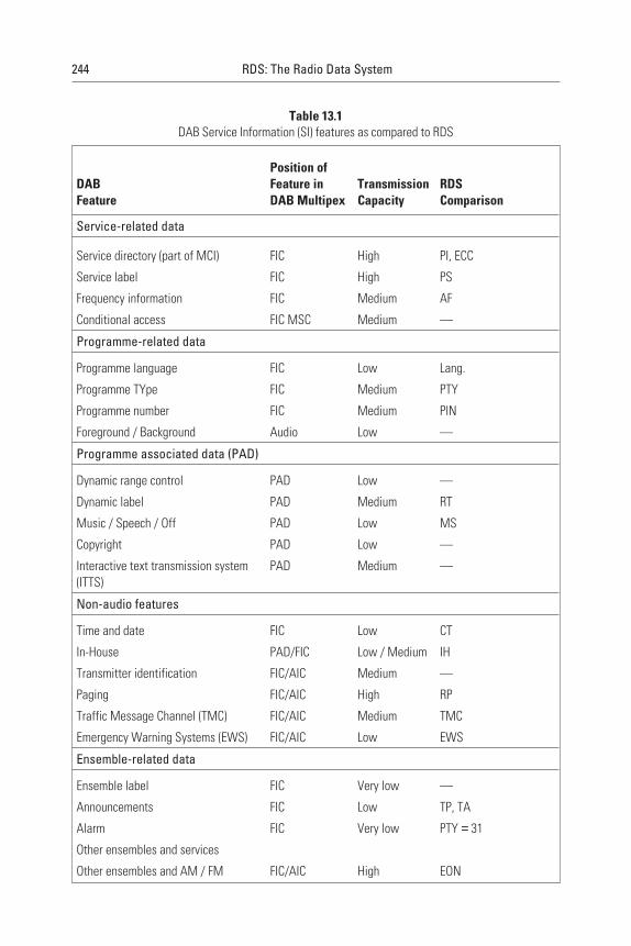
244 RDS: The Radio Data System
Table 13.1DAB Service Information (SI) features as compared to RDS
DABFeature
Position ofFeature inDAB Multipex
TransmissionCapacity
RDSComparison
Service-related data
Service directory (part of MCI) FIC High PI, ECC
Service label FIC High PS
Frequency information FIC Medium AF
Conditional access FIC MSC Medium —
Programme-related data
Programme language FIC Low Lang.
Programme TYpe FIC Medium PTY
Programme number FIC Medium PIN
Foreground / Background Audio Low —
Programme associated data (PAD)
Dynamic range control PAD Low —
Dynamic label PAD Medium RT
Music / Speech / Off PAD Low MS
Copyright PAD Low —
Interactive text transmission system(ITTS)
PAD Medium —
Non-audio features
Time and date FIC Low CT
In-House PAD/FIC Low / Medium IH
Transmitter identification FIC/AIC Medium —
Paging FIC/AIC High RP
Traffic Message Channel (TMC) FIC/AIC Medium TMC
Emergency Warning Systems (EWS) FIC/AIC Low EWS
Ensemble-related data
Ensemble label FIC Very low —
Announcements FIC Low TP, TA
Alarm FIC Very low PTY = 31
Other ensembles and services
Other ensembles and AM / FM FIC/AIC High EON

Reference is also made to how they correspond to RDS features; however, usu-ally they are enhanced. An example is the service label (“BBC Radio One”),which has sixteen characters at maximum in DAB, but has only eight at maxi-mum in RDS (“BBC R1”). The service label in DAB is thus eight characterslonger than the PS name used in RDS. It was designed to give greater freedomin describing a service. To maintain compatibility with RDS, the service label isaccompanied by additional information that allows up to eight characters to besuppressed in a receiver with a limited display. All features using a text displayin RDS and DAB use the same character tables as those detailed in Appendix I.
The frequency information feature provides a cross-reference to alterna-tive sources of service. It is similar to the RDS AF feature, which provides a listof alternative frequencies and permits programme continuity when a mobilereceiver moves across coverage area boundaries and requires retuning to obtainbetter reception. Although DAB is suited to operation in a network where alltransmitters operate on a single frequency network (SFN), DAB multiplexesmay also be available via satellite or cable, and these multiplexes may operate indifferent frequency ranges and DAB modes.
Data capacities for DAB data services are significantly higher than is pos-sible with RDS, and in Table 13.1 they are indicated in only very broad termsbecause the requirements depend on a wide range of options. “Very low” meansa few bits per second and “high” indicates 10 kbps or more.
13.4.3 RDS/DAB Interoperability
When DAB services duplicate those radio programmes available on VHF/FM,and when DAB signals are not yet widely available (especially during the yearswhen new DAB services are being introduced), there will definitely be areaswhere some services will only be available on VHF/FM. Then, the DAB fre-quency information feature will have to provide for cross-referencing to FM(and in theory, also to AM), and it shall consequently support the full range ofradio frequencies foreseen for DAB, AM, and FM.
In the years 1996–1997, the RDS Forum established a working group toexamine how various radio data features of the RDS and DAB systems couldbest be implemented by both broadcasters and receivers to allow a user to bene-fit from both systems used in his or her receiver. This was done with the view ofavoiding confusion for the technically uninformed listener. Neither systemshould be modified, the only objective being to better understand how the sys-tem features should be applied to achieve these objectives. The findings of theworking group are, at the time of writing, being considered for inclusion inthe RDS guidelines that the EBU and the RDS Forum intend to publishduring 1998.
Outlook: RDS and Other Broadcast Data Systems for Radio 245
13.5 Digital Radio by Satellite
Satellite radio is currently available in Europe via the digital satellite radio(DSR) system and the SES/ADR (ASTRA Digital Radio) system. DSR wasonly used in Germany, and it was unsuccessful in capturing a European marketbecause it was conceived in the early 1980s for fixed antenna reception only. Inthe DSR implementation phase, starting in 1985, DAB was already beingdeveloped, and contrary to DSR, it was conceived for mobile reception whilepermitting fixed reception as well. This made DSR unattractive and, finally,redundant.
Some years later, in 1994, SES introduced on its ASTRA satellites theADR system. Because of its limitation of fixed reception only (a similar limita-tion to DSR), it is likely to be around for only a few more years. ADR uses ananalogue television signal to carry in a piggyback manner a modest number ofradio channels as well as TV. In those European countries where the ASTRAsatellite system is popular, ADR is inexpensive as a transmission medium, andreceivers are available at a marginal cost increase to the ASTRA satellite TVdecoders, which are generally available at low cost. ADR can be operated toinclude an in-house data channel that makes use of the Universal EncoderCommunication Protocol, as described in Chapter 11. This permits the feedingof a network of terrestrial radio transmitters, where each individual transmittercan be fed in a regional context with RDS data as required for the terrestrialoperation.
Another system to come soon is DVB-S. Intended primarily for digitaltelevision, it can provide radio to smaller sized dishes than ADR, but thesedishes still have to be fixed and have a clear line of sight to the satellite.
The year 1998 may be a landmark year for digital radio by satellite,because a new radio system, called WorldSpace, will be launched and anotherdigital radio system, Mediastar, may come in three years’ time.
WorldSpace aims at providing low-cost digital satellite radio to portionsof Africa, the Middle East, Latin America, the Caribbean, and Asia. The trans-mission system will not use DAB, but a proprietary system instead, detailsof which are not yet in the public domain. Two of WorldSpace’s satellites areexpected to be launched in 1998, with service beginning in late 1998 or early1999. Later, the system may be used for the United States as well. It has littlesignificance for Europe, at least for now.
Mediastar, on the other hand, is intended to provide Europe with satelliteradio using DAB, with operation planned to start in 2001 using the 1.5 GHzfrequency range. Three low-orbit satellites are planned, to be positioned overthe target coverage areas. However, what impact these systems will have on thefuture of radio is generally unknown.
246 RDS: The Radio Data System
References
[1] Schall, N., “Digital developments in Amplitude-Modulated broadcasting,” Proceedings ofthe FES/ITU/PRO AV AFRICA/URTNA Regional Symposium in sound and television broad-casting for Africa, International Telecommunication Union, Geneva, Switzerland, 1997,pp. 459–463.
[2] Kuroda, T., et al., “Transmission scheme of high capacity FM multiplex BroadcastingSystem,” IEEE Trans. on Broadcasting, Vol. 42, No. 3, 1996, pp. 245–250.
[3] ITU R Recommendation BS.1194-1, System for multiplexing FM sound broadcasts witha sub-carrier data channel having a relatively large transmission capacity for stationaryand mobile reception, International Telecommunication Union, Geneva, Switzerland,March 1998.
[4] ETSI, ETS 300 751 Radio broadcasting systems, System for Wireless InfotainmentForwarding and Teledistribution (SWIFT), ETSI Secretariat, F-06921 Sophia AntipolisCedex, France, 1997.
[5] Andersson, R., “The possibilities of using DARC/SWIFT for datacasting,” Proceedings ofthe Montreux International Radio Symposium, 1998.
[6] ETSI, ETS 300 401 Radio broadcasting systems, Digital Audio Broadcasting (DAB) tomobile, portable and fixed receivers, ETSI Secretariat, F-06921 Sophia Antipolis Cedex,France, 1996.
[7] Van de Laar, H., et al., “Towards the next generation of DAB receivers,” EBU Review-Technical, No. 272, Summer 1997.
[8] Müller-Römer, F., “DAB Progress Report 1997,” EBU Review-Technical, No. 274,Winter 1997.
[9] Plenge, G., “DAB - A new sound broadcasting system - State of the development - Routesto its introduction,” EBU Review-Technical, No. 246, April 1991.
[10] Schneeberger, G., “Datendienste mit DAB,” Deutsche DAB Plattform e.V., Am Moosfeld31, D-81829 München, Germany, 1996.
[11] Lauterbach, T., Digital Audio Broadcasting: Grundlagen, Anwendungen und Einführung vonDAB, Franzis-Verlag Feldkichen, Germany, ISBN 3-7723-4842-4, 1996.
Outlook: RDS and Other Broadcast Data Systems for Radio 247
Appendix A
Appendix AModulation of the RDS Data Signal
A.1 Subcarrier Frequency
The RDS data signal is carried on a subcarrier which is added to the stereomultiplex signal (or monophonic signal as appropriate) at the input tothe VHF/FM transmitter. Block diagrams of the data source equipment atthe transmitter and a typical receiver arrangement are shown in Figures A.1and A.2, respectively.
During stereo broadcasts, the subcarrier frequency will be locked to thethird harmonic of the 19 kHz pilot-tone. Since the tolerance on the frequencyof the 19 kHz pilot-tone is ±2 Hz (see ITU-R Recommendation BS.450-2),the tolerance on the frequency of the subcarrier during stereo broadcasts is±6 Hz.
During monophonic broadcasts, the frequency of the subcarrier will be57 kHz ± 6 Hz.
A.2 Subcarrier Phase
During stereo broadcasts, the subcarrier will be locked either in phase or inquadrature to the third harmonic of the 19 kHz pilot-tone. The tolerance onthis phase angle is ±10°.
249
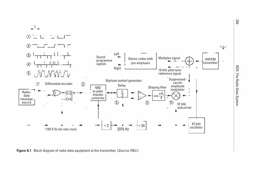
250RDS:The
RadioData
System
Stereo coder withpre-emphasis
td
1
1
2
2
3
3
5
5
4
4
Radio-data
messagesource
Differential encoder
CLK
D Q
1187.5 Hz bit-rate clock
Biphase symbol generator
NRZto polarimpulse
convertor
Delay
td
2−+
Soundprogrammesignals
Left
Right
Multiplex signal
19 kHz pilot-tonereference signal
Shaping filter
Suppressed-carrier
amplitudemodulator
cosπftd
4
57 kHzsubcarrier
VHF/FMtransmitter
57 kHzoscillator÷ 2 ÷ 24
2375 Hz
Figure A.1 Block diagram of radio-data equipment at the transmitter. (Source: EBU.)
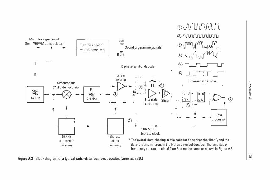
Appendix
A251
1
1
2
2
3
3
5
5
6
6
4
4
Multiplex signal input(from VHF/FM demodulator) Stereo decoder
with de-emphasis Sound programme signals
Left
Right
Synchronous57 kHz demodulator
57 kHz 2.4 kHz
F *1
57 kHzsubcarrierrecovery
Bit-rateclock
recovery
Biphase symbol decoder
Linearinverter
1187.5 Hzbit-rate clock
Integrateand dump
Slicer
D Q
CLK
D Q
CLK
Differential decoder
Dataprocessor
* The overall data-shaping in this decoder comprises the filter F and thedata-shaping inherent in the biphase symbol decoder. The amplitude/frequency characteristic of filter F isnot the same as shown in Figure A.3.
1
1
**
Figure A.2 Block diagram of a typical radio-data receiver/decoder. (Source: EBU.)
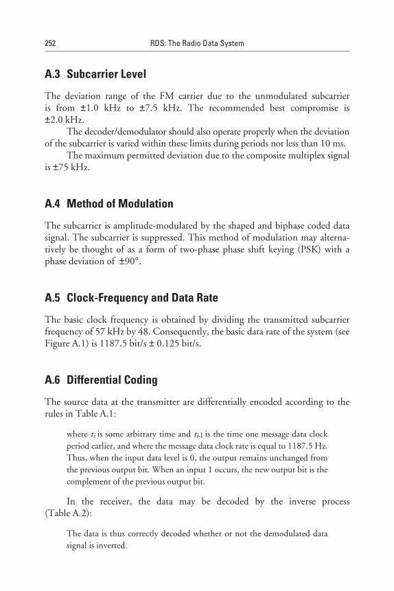
A.3 Subcarrier Level
The deviation range of the FM carrier due to the unmodulated subcarrieris from ±1.0 kHz to ±7.5 kHz. The recommended best compromise is±2.0 kHz.
The decoder/demodulator should also operate properly when the deviationof the subcarrier is varied within these limits during periods not less than 10 ms.
The maximum permitted deviation due to the composite multiplex signalis ±75 kHz.
A.4 Method of Modulation
The subcarrier is amplitude-modulated by the shaped and biphase coded datasignal. The subcarrier is suppressed. This method of modulation may alterna-tively be thought of as a form of two-phase phase shift keying (PSK) with aphase deviation of ±90°.
A.5 Clock-Frequency and Data Rate
The basic clock frequency is obtained by dividing the transmitted subcarrierfrequency of 57 kHz by 48. Consequently, the basic data rate of the system (seeFigure A.1) is 1187.5 bit/s ± 0.125 bit/s.
A.6 Differential Coding
The source data at the transmitter are differentially encoded according to therules in Table A.1:
where ti is some arbitrary time and ti-l is the time one message data clockperiod earlier, and where the message data clock rate is equal to 1187.5 Hz.Thus, when the input data level is 0, the output remains unchanged fromthe previous output bit. When an input 1 occurs, the new output bit is thecomplement of the previous output bit.
In the receiver, the data may be decoded by the inverse process(Table A.2):
The data is thus correctly decoded whether or not the demodulated datasignal is inverted.
252 RDS: The Radio Data System
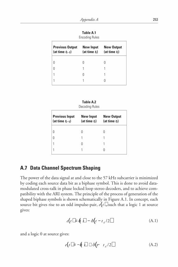
A.7 Data Channel Spectrum Shaping
The power of the data signal at and close to the 57 kHz subcarrier is minimizedby coding each source data bit as a biphase symbol. This is done to avoid data-modulated cross-talk in phase locked loop stereo decoders, and to achieve com-patibility with the ARI system. The principle of the process of generation of theshaped biphase symbols is shown schematically in Figure A.1. In concept, eachsource bit gives rise to an odd impulse-pair, ( )e t , such that a logic 1 at sourcegives:
( ) ( ) ( )e t t t t d= − −δ δ /2 (A.1)
and a logic 0 at source gives:
( ) ( ) ( )e t t t t d= − + −δ δ /2 (A.2)
Appendix A 253
Table A.1Encoding Rules
Previous Output(at time ti−1)
New Input(at time ti)
New Output(at time ti)
0 0 0
0 1 1
1 0 1
1 1 0
Table A.2Decoding Rules
Previous Input(at time ti−1)
New Input(at time ti)
New Output(at time ti)
0 0 0
0 1 1
1 0 1
1 1 0
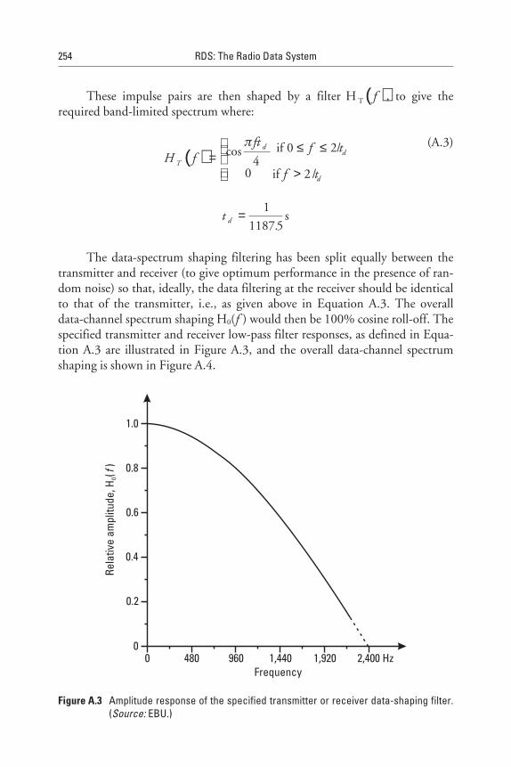
These impulse pairs are then shaped by a filter ( )H T f , to give therequired band-limited spectrum where:
( )H fft f t
f tT
dd
d
=
≤ ≤
>
cos /
/
π
40
0 2
2
if
if
(A.3)
t d =1
1187 5.s
The data-spectrum shaping filtering has been split equally between thetransmitter and receiver (to give optimum performance in the presence of ran-dom noise) so that, ideally, the data filtering at the receiver should be identicalto that of the transmitter, i.e., as given above in Equation A.3. The overalldata-channel spectrum shaping H0(f ) would then be 100% cosine roll-off. Thespecified transmitter and receiver low-pass filter responses, as defined in Equa-tion A.3 are illustrated in Figure A.3, and the overall data-channel spectrumshaping is shown in Figure A.4.
254 RDS: The Radio Data System
Rela
tive
ampl
itude
,H(
)O
f
Frequency0 480 960 1,440 1,920 2,400 Hz
0
0.2
0.4
0.6
0.8
1.0
Figure A.3 Amplitude response of the specified transmitter or receiver data-shaping filter.(Source: EBU.)

The spectrum of the transmitted biphase coded radio data signal is shownin Figure A.5 and the time function of a single biphase symbol (as transmitted)
Appendix A 255
Rela
tive
ampl
itude
,H(
)T
f
Frequency0 480 960 1,440 1,920 2,400 Hz
0
0.2
0.4
0.6
0.8
1.0
Figure A.4 Amplitude response of the combined transmitter and receiver data-shapingfilters. (Source: EBU.)
Rela
tive
ampl
itude
10
0.5
−2,400 −1,200 −240 0 240 1,200 2,400 HzModulating frequency
Figure A.5 Spectrum of biphase coded radio data signals. (Source: EBU.)
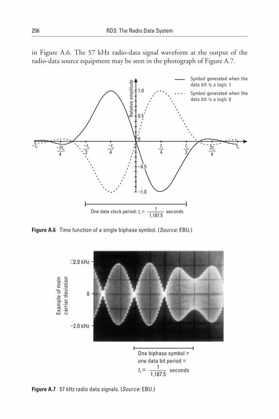
in Figure A.6. The 57 kHz radio-data signal waveform at the output of theradio-data source equipment may be seen in the photograph of Figure A.7.
256 RDS: The Radio Data System
Rela
tive
ampl
itude
1.0
0
−1.0
0.5
−0.5
One data clock period: secondstd = 11,187.5
−td −34
td 34td
−td
2−td
4td
2td
td
4
Symbol generated when thedata bit is a logic 1
Symbol generated when thedata bit is a logic 0
Figure A.6 Time function of a single biphase symbol. (Source: EBU.)
+2.0 kHz
−2.0 kHz
0
One biphase symbolone data bit period
==
td = 11,187.5
seconds
Exam
ple
ofm
ain
carr
ierd
evia
tion
Figure A.7 57 kHz radio data signals. (Source: EBU.)

References
[1] CENELEC EN 50067:1998, “Specifications of the Radio Data System (RDS) forVHF/FM broadcasting, European Committee for Electrical Standardization (CENELEC),35B Rue de Stassart, B-1050, Brussels, April 1988.
Appendix A 257
Appendix B
Appendix BRDS Data Decoding
B.1 Introduction
One form of a biphase symbol decoder was shown in Figure A.2 ofAppendix A. In that section, it was also explained that the biphase symbol gen-erator produces two impulses for each input bit. The resultant impulse train isthe cosine-shaped filtered one, and then modulated on the 57 kHz subcarrier,the basic data rate being 1187.5 bps (i.e., 57 kHz divided by 48, which is theclock frequency). The RDS demodulator/decoder techniques, as well as theirfunctionality and corresponding integrated circuits, were all explained inChapter 12. In the following section, we deal entirely with decoding the base-band data stream.
B.2 Baseband Coding Structure
Figure B.1 shows the structure of the baseband coding. The largest elementin the structure is called a “group” of 104 bits each. Each group is comprised of4 blocks of 26 bits each. Each block is comprised of an information word and acheck word. Each information word is comprised of 16 bits. Each check wordis comprised of 10 bits.
259
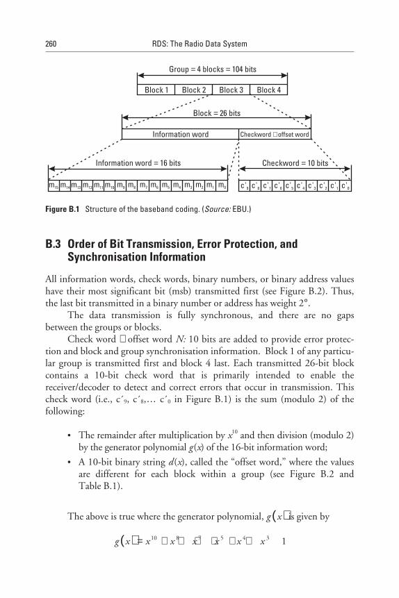
B.3 Order of Bit Transmission, Error Protection, andSynchronisation Information
All information words, check words, binary numbers, or binary address valueshave their most significant bit (msb) transmitted first (see Figure B.2). Thus,the last bit transmitted in a binary number or address has weight 2°.
The data transmission is fully synchronous, and there are no gapsbetween the groups or blocks.
Check word + offset word N: 10 bits are added to provide error protec-tion and block and group synchronisation information. Block 1 of any particu-lar group is transmitted first and block 4 last. Each transmitted 26-bit blockcontains a 10-bit check word that is primarily intended to enable thereceiver/decoder to detect and correct errors that occur in transmission. Thischeck word (i.e., c´9, c´8,… c´0 in Figure B.1) is the sum (modulo 2) of thefollowing:
• The remainder after multiplication by x10 and then division (modulo 2)by the generator polynomial g (x) of the 16-bit information word;
• A 10-bit binary string d (x), called the “offset word,” where the valuesare different for each block within a group (see Figure B.2 andTable B.1).
The above is true where the generator polynomial, ( )g x is given by
( )g x x x x x x x= + + + + + +10 8 7 5 4 3 1
260 RDS: The Radio Data System
Group 4 blocks 104 bits= =
Block 1 Block 2 Block 3 Block 4
Block 26 bits=
Information word
Information word 16 bits=
Checkword offset word+
Checkword 10 bits=
m15 m14 m13 m12 m11 m10 m9 m8 m7 m6 m5 m4 m3 m2 m1 m0 c'9 c'8 c'7 c'6 c'5 c'4 c'3 c'2 c'1 c'0
Figure B.1 Structure of the baseband coding. (Source: EBU.)
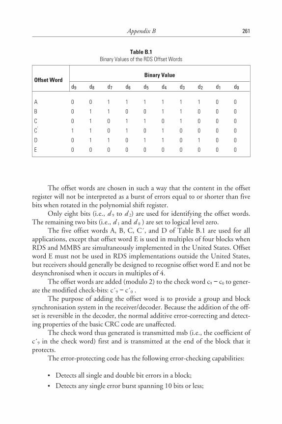
The offset words are chosen in such a way that the content in the offsetregister will not be interpreted as a burst of errors equal to or shorter than fivebits when rotated in the polynomial shift register.
Only eight bits (i.e., d 9 to d 2) are used for identifying the offset words.The remaining two bits (i.e., d 1 and d 0 ) are set to logical level zero.
The five offset words A, B, C, C´, and D of Table B.1 are used for allapplications, except that offset word E is used in multiples of four blocks whenRDS and MMBS are simultaneously implemented in the United States. Offsetword E must not be used in RDS implementations outside the United States,but receivers should generally be designed to recognise offset word E and not bedesynchronised when it occurs in multiples of 4.
The offset words are added (modulo 2) to the check word c9 − c0 to gener-ate the modified check-bits: c´9 − c´0 .
The purpose of adding the offset word is to provide a group and blocksynchronisation system in the receiver/decoder. Because the addition of the off-set is reversible in the decoder, the normal additive error-correcting and detect-ing properties of the basic CRC code are unaffected.
The check word thus generated is transmitted msb (i.e., the coefficient ofc´9 in the check word) first and is transmitted at the end of the block that itprotects.
The error-protecting code has the following error-checking capabilities:
• Detects all single and double bit errors in a block;
• Detects any single error burst spanning 10 bits or less;
Appendix B 261
Table B.1Binary Values of the RDS Offset Words
Offset WordBinary Value
d9 d8 d7 d6 d5 d4 d3 d2 d1 d0
A 0 0 1 1 1 1 1 1 0 0
B 0 1 1 0 0 1 1 0 0 0
C 0 1 0 1 1 0 1 0 0 0
C‘ 1 1 0 1 0 1 0 0 0 0
D 0 1 1 0 1 1 0 1 0 0
E 0 0 0 0 0 0 0 0 0 0
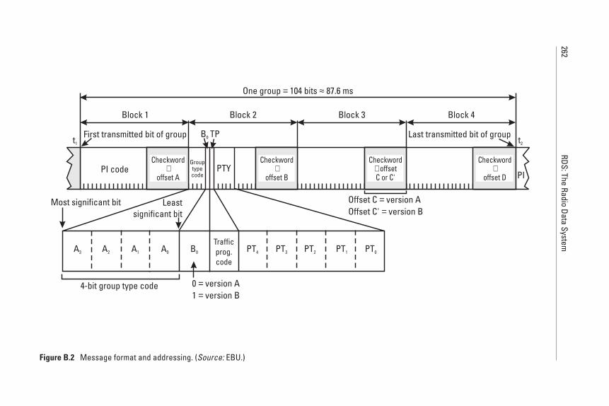
262RDS:The
RadioData
System
Checkword+
offset A
Checkword
offset B+
Checkwordoffset
C or C'+
Checkword
offset D+PI code
Grouptypecode
B0 TP
PTYPI
t1
First transmitted bit of group Last transmitted bit of group
Block 1 Block 2 Block 3 Block 4
t2
One group 104 bits 87.6 ms= ≈
Offset C version AOffset C' version B
==
Most significant bit Leastsignificant bit
A3 A2 A1 A0 B0
Trafficprog.code
PT4 PT3 PT2 PT1 PT0
4-bit group type code 0 version A1 version B
==
Figure B.2 Message format and addressing. (Source: EBU.)
• Detects about 99.8% of bursts spanning 11 bits and about 99.9% ofall longer bursts.
The code is also an optimal burst error-correcting code and is capable ofcorrecting any single burst of a span of five bits or less.
The blocks within each group are identified by the offset words A, B, C(or C´ instead of C), and D added to blocks 1, 2, 3, and 4, respectively, in eachtype A (or, with offset C´, type B) group.
The beginnings and ends of the data blocks may be recognised in thereceiver decoder by using the fact that the error-checking decoder will, with ahigh level of confidence, detect block synchronisation slip as well as additiveerrors. This system of block synchronisation is made reliable by the addition ofthe offset words (which also serve to identify the blocks within the group).These offset words destroy the cyclic property of the basic code so that in themodified code, cyclic shifts of code words do not give rise to other code words.
B.4 Message Format and Addressing of Groups
The basic design principles underlying the message format and addressingstructure are as follows:
• The messages that are to be repeated most frequently, and for which ashort acquisition time is required (i.e., PI, PTY and TP codes, as wellas the group type code) occupy the same fixed positions within everygroup. They can therefore be decoded without reference to any blockoutside the one that contains the information.
• There is no fixed rhythm of repetition of the various types of group;that is, there is ample flexibility to interleave the various kinds of mes-sages to suit the needs of the transmission operator at any given time,and to allow for future developments.
• This requires addressing to identify the information content of thoseblocks that are not dedicated to the high-repetition-rate information.
• Each group is, so far as possible, fully addressed to identify the infor-mation content of the various blocks.
• The mixture of different kinds of messages within any one group isminimised; for example, one group type is reserved for basic tuninginformation, another for RadioText, and so on. This is importantso that broadcasters who do not wish to transmit certain kinds of
Appendix B 263
messages are not forced to waste channel capacity by transmittinggroups with unused blocks. Instead, they are able to repeat more fre-quently those group types that contain the messages they want totransmit.
• To allow for future applications, the data formatting has been madeflexible. For example, the ODA feature (see Chapter 9) may be usedfor the definition of any (public domain or proprietary) futureapplication.
The main features of the message structure have been illustrated inFigure B.2. These may be seen to be as follows:
1. The first block in every group always contains a PI code.
2. The first four bits of the second block of every group are allocated to afour-bit code that specifies the application of the group (group typenumber address). Groups will be referred to as type number 0 to 15according to the binary weighting A3 = 8, A2 = 4, A1 = 2, A0 = 1 (seeFigure B.2). For each type (0 to 15), one of two versions, A or B, canbe defined. The version is specified by the fifth bit (B0) of block 2 asfollows:
a. B0 = 0 (type A versions; e.g., 0A, 1A, etc.): the PI code is insertedin block 1 only.
b. B0 = 1 (type B versions; e.g., 0B, 1B, etc.): the PI code is insertedin block 1 and block 3 of all group types.
In general, any mixture of type A and B groups is transmitted.
3. The PTY and TP identification occupy fixed locations in block 2 ofevery group.
As already stated above, the PI, PTY, and TP codes can be decoded with-out reference to any block outside the one that contains the information. Thisis essential to minimise acquisition time for these kinds of messages andto retain the advantages of the short (26-bit) block length. To permit this tobe done for the PI codes in block 3 of version B groups, a special offset word(which is called C´) is used in block 3 of version B groups. The occurrence ofoffset C´ in block 3 of any group can then be used to indicate directly thatblock 3 is a PI code, without any reference to the value of B0 in block 2.
264 RDS: The Radio Data System

References
[1] CENELEC EN 50067:1998-Specifications of the Radio Data System (RDS) forVHF/FM broadcasting, European Committee for Electrical Standardisation (CENELEC),35B rue de Stassart, B-1050 Brussels, April 1998.
[2] Parnall, S., “Decoding RDS, Electronics & Wireless World,” Part 1, Feb. 1989,pp. 148–152, Part 2, March 1989, pp. 284–287.
[3] Ohsmann, M., “Radio Data System (RDS) Decoder,” Elektor Electronics, Feb. 1991,pp. 56–61.
Appendix B 265
Appendix C
Appendix CRDS Reception Reliability
C.1 Introduction
Field tests carried out by a number of broadcasters’ research laboratories allcame to the same conclusions [1–3].
Relatively low RDS data injection levels, say ±1 kHz deviation, offer areliable data system, but only under receiving conditions with little or no multi-path effects (e.g., in open, relatively flat country with good line of sight fromthe transmitter). Multipath effects occur due to reflections of the transmittedsignal by high-rise buildings or in mountainous terrain. In a moving receiver,once multipath effects occur, there is a sharp decrease in reception reliability.However, reliability can be increased by data repetition because multipathreception has the effect of reducing reception performance for fractions of asecond as the receiver moves from good to poor to good reception locations.
C.2 Bit Error Rate
Curve (a) in Figure C.1 shows the bit error rate of the experimental referenceRDS demodulator measured as a function of the power applied at the aerialinput of the VHF/FM receiver. The VHF/FM receiver used in these measure-ments had a noise figure of 5.5 dB. For the purposes of comparison, the theo-retical bit error rate expected according to theory is given as curve (b). It may be
267
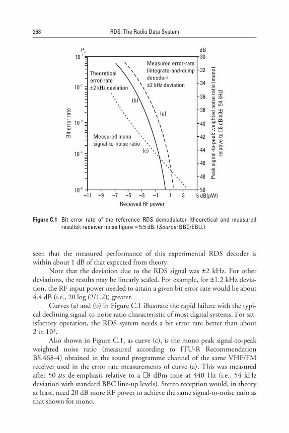
seen that the measured performance of this experimental RDS decoder iswithin about 1 dB of that expected from theory.
Note that the deviation due to the RDS signal was ±2 kHz. For otherdeviations, the results may be linearly scaled. For example, for ±1.2 kHz devia-tion, the RF input power needed to attain a given bit error rate would be about4.4 dB (i.e., 20 log (2/1.2)) greater.
Curves (a) and (b) in Figure C.1 illustrate the rapid failure with the typi-cal declining signal-to-noise ratio characteristic of most digital systems. For sat-isfactory operation, the RDS system needs a bit error rate better than about2 in 10².
Also shown in Figure C.1, as curve (c), is the mono peak signal-to-peakweighted noise ratio (measured according to ITU-R RecommendationBS.468-4) obtained in the sound programme channel of the same VHF/FMreceiver used in the error rate measurements of curve (a). This was measuredafter 50 µs de-emphasis relative to a +8 dBm tone at 440 Hz (i.e., 54 kHzdeviation with standard BBC line-up levels). Stereo reception would, in theoryat least, need 20 dB more RF power to achieve the same signal-to-noise ratio asthat shown for mono.
268 RDS: The Radio Data System
Measured error-rate(integrate-and-dumpdecoder)±2 kHz deviation
Measured monosignal-to-noise ratio
Theoreticalerror-rate
2 kHz deviation±
(a)
(b)
(c)
30
32
34
36
38
40
42
44
46
48
50
dB
Peak
sign
al-to
-pea
kw
eigh
ted
nois
era
tio(m
ono)
rela
tive
to8
dBm
0(
54kH
z)+
±
−11 −9 −7 −5 −3 −1 1 3 5 dB(pW)Received RF power
10−1
10−2
10−3
10−4
10−5
Pe
Bite
rror
rate
Figure C.1 Bit error rate of the reference RDS demodulator (theoretical and measuredresults): receiver noise figure = 5.5 dB. (Source: BBC/EBU.)
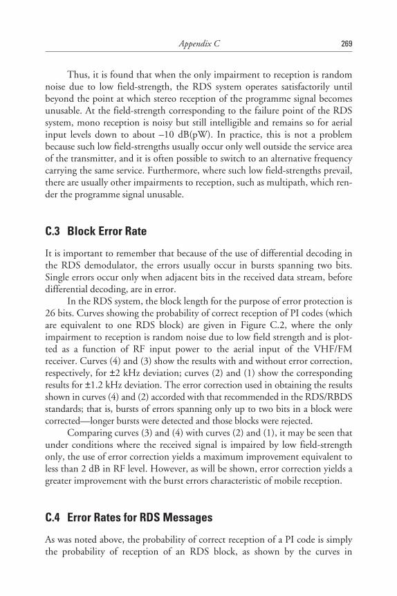
Thus, it is found that when the only impairment to reception is randomnoise due to low field-strength, the RDS system operates satisfactorily untilbeyond the point at which stereo reception of the programme signal becomesunusable. At the field-strength corresponding to the failure point of the RDSsystem, mono reception is noisy but still intelligible and remains so for aerialinput levels down to about –10 dB(pW). In practice, this is not a problembecause such low field-strengths usually occur only well outside the service areaof the transmitter, and it is often possible to switch to an alternative frequencycarrying the same service. Furthermore, where such low field-strengths prevail,there are usually other impairments to reception, such as multipath, which ren-der the programme signal unusable.
C.3 Block Error Rate
It is important to remember that because of the use of differential decoding inthe RDS demodulator, the errors usually occur in bursts spanning two bits.Single errors occur only when adjacent bits in the received data stream, beforedifferential decoding, are in error.
In the RDS system, the block length for the purpose of error protection is26 bits. Curves showing the probability of correct reception of PI codes (whichare equivalent to one RDS block) are given in Figure C.2, where the onlyimpairment to reception is random noise due to low field strength and is plot-ted as a function of RF input power to the aerial input of the VHF/FMreceiver. Curves (4) and (3) show the results with and without error correction,respectively, for ±2 kHz deviation; curves (2) and (1) show the correspondingresults for ±1.2 kHz deviation. The error correction used in obtaining the resultsshown in curves (4) and (2) accorded with that recommended in the RDS/RBDSstandards; that is, bursts of errors spanning only up to two bits in a block werecorrected—longer bursts were detected and those blocks were rejected.
Comparing curves (3) and (4) with curves (2) and (1), it may be seen thatunder conditions where the received signal is impaired by low field-strengthonly, the use of error correction yields a maximum improvement equivalent toless than 2 dB in RF level. However, as will be shown, error correction yields agreater improvement with the burst errors characteristic of mobile reception.
C.4 Error Rates for RDS Messages
As was noted above, the probability of correct reception of a PI code is simplythe probability of reception of an RDS block, as shown by the curves in
Appendix C 269
Figure C.2. The same is also true for all other kinds of messages that occupyfixed positions within all RDS group types and can therefore be decoded with-out reference to any information outside the block that contains them.Included in this category are PI, PTY, and TP identification.
Other messages require correct decoding of the group type address, andperhaps other information such as the segment address for PS codes. Inevitably,the more RDS blocks that a message and its related addressing occupy, thelower the probability of correct reception of the complete message. However, inmost applications needing long messages (e.g., RadioText), it is not necessaryto receive the whole message correctly before making use of it; missing or erro-neous characters can easily be tolerated on displayed messages.
Curves showing the probability of correct reception of PI, PS, and RTmessages when the only impairment to reception is random noise due to lowfield-strength are given in Figure C.3. The deviation due to the RDS signal was±2 kHz, and two-bit burst error correction was applied.
270 RDS: The Radio Data System
Frequency deviation1 1.2 kHz2 1.2 kHz, correction3 2.0 kHz4 2.0 kHz, correction
====
Perc
enta
geof
PIm
essa
ges
corr
ectly
rece
ived
100
90
80
70
60
50
40
30
20
10
0
%
−8 −6 −4 −2 0 2 4 dB(pW)Received RF power
4 3 2 1
Figure C.2 Influence of the RF level, error correction, and frequency deviation on thebroadcast reliability. (Source: IRT/EBU.)
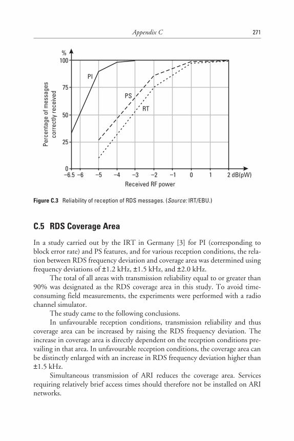
C.5 RDS Coverage Area
In a study carried out by the IRT in Germany [3] for PI (corresponding toblock error rate) and PS features, and for various reception conditions, the rela-tion between RDS frequency deviation and coverage area was determined usingfrequency deviations of ±1.2 kHz, ±1.5 kHz, and ±2.0 kHz.
The total of all areas with transmission reliability equal to or greater than90% was designated as the RDS coverage area in this study. To avoid time-consuming field measurements, the experiments were performed with a radiochannel simulator.
The study came to the following conclusions.In unfavourable reception conditions, transmission reliability and thus
coverage area can be increased by raising the RDS frequency deviation. Theincrease in coverage area is directly dependent on the reception conditions pre-vailing in that area. In unfavourable reception conditions, the coverage area canbe distinctly enlarged with an increase in RDS frequency deviation higher than±1.5 kHz.
Simultaneous transmission of ARI reduces the coverage area. Servicesrequiring relatively brief access times should therefore not be installed on ARInetworks.
Appendix C 271
Perc
enta
geof
mes
sage
sco
rrec
tlyre
ceiv
ed100
75
50
25
0
%
Received RF power−6.5 −6 −5 −4 −3 −2 −1 0 1 2 dB(pW)
PI
PS
RT
Figure C.3 Reliability of reception of RDS messages. (Source: IRT/EBU.)
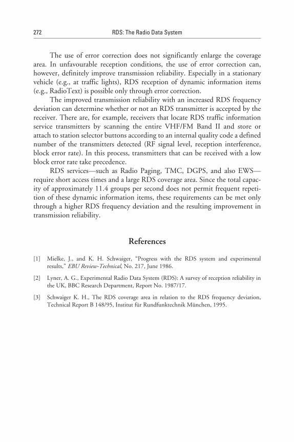
The use of error correction does not significantly enlarge the coveragearea. In unfavourable reception conditions, the use of error correction can,however, definitely improve transmission reliability. Especially in a stationaryvehicle (e.g., at traffic lights), RDS reception of dynamic information items(e.g., RadioText) is possible only through error correction.
The improved transmission reliability with an increased RDS frequencydeviation can determine whether or not an RDS transmitter is accepted by thereceiver. There are, for example, receivers that locate RDS traffic informationservice transmitters by scanning the entire VHF/FM Band II and store orattach to station selector buttons according to an internal quality code a definednumber of the transmitters detected (RF signal level, reception interference,block error rate). In this process, transmitters that can be received with a lowblock error rate take precedence.
RDS services—such as Radio Paging, TMC, DGPS, and also EWS—require short access times and a large RDS coverage area. Since the total capac-ity of approximately 11.4 groups per second does not permit frequent repeti-tion of these dynamic information items, these requirements can be met onlythrough a higher RDS frequency deviation and the resulting improvement intransmission reliability.
References
[1] Mielke, J., and K. H. Schwaiger, “Progress with the RDS system and experimentalresults,” EBU Review-Technical, No. 217, June 1986.
[2] Lyner, A. G., Experimental Radio Data System (RDS): A survey of reception reliability inthe UK, BBC Research Department, Report No. 1987/17.
[3] Schwaiger K. H., The RDS coverage area in relation to the RDS frequency deviation,Technical Report B 148/95, Institut für Rundfunktechnik München, 1995.
272 RDS: The Radio Data System
Appendix D
Appendix DRequired Data Repetition Rates forProgramme-Related RDS Features
The mixture of different kinds of messages within any one group is minimised;for example, one group type is reserved for basic tuning information, anotherfor RadioText, and so on. This is important so that broadcasters that donot wish to transmit messages of certain kinds are not forced to waste channelcapacity by transmitting groups with unused blocks. Instead, they are able torepeat more frequently those group types that contain the messages they wantto transmit. There is no fixed rhythm of repetition of the various types ofgroup; that is, there is ample flexibility to interleave the various kinds of mes-sages to suit the needs of the users at any given time and to allow for futuredevelopments.
A total of four type 0A groups are required to transmit the entire PS nameand therefore four type 0A groups will be required per second. The repetitionrate of the type 0A group may be reduced if more capacity is needed for otherapplications (see Table D.1). However, with EON receivers, search tuning isaffected by the repetition rate of type 0 groups. A minimum of two type 0Agroups per second is necessary to ensure correct functioning of PS and AF fea-tures. It should be noted that in this case, transmission of the complete PS willtake two seconds. However, under typical reception conditions, the introduc-tion of errors will cause the receiver to take four seconds or more to acquire thePS name for display.
273
Table D.1Recommended Repetition Rates for the Programme Related Features
Main FeaturesGroup Types That ContainThis Information
Appropriate RepetitionRate Per Second
Programme Identification (PI) code
Programme Type (PTY) code
Traffic Programme (TP) identificationcode
Programme Service (PS) name 4)
Alternative Frequency (AF) code pairs
Traffic Announcement (TA) code
Decoder Identification (DI) code
Music Speech (MS) code
RadioText (RT) message
Enhanced Other Networks (EON)information
All
All
All
0A, 0B
0A
0A, 0B, 15B
0A, 0B, 15B
0A, 0B, 15B
2A, 2B
14A, 14B
11.4 1)
11.4 1)
11.4 1)
1
4
4
1
4
0.2 2)
Up to 2 3)
1) Valid codes for this item will normally be transmitted with at least this repetition rate wheneverthe transmitter carries a normal broadcast programme.
2) A total of 16 type 2A groups are required to transmit a 64-character RT message and therefore 3.2type 2A groups will be required per second.
3) The maximum cycle time for the transmission of all data relating to all cross-referencedPSs shall be less than two minutes.
4) PS must only be used for identifying the PS, and it must not be used for other messages givingsequential information.
When the PIN or slow-labelling is implemented, type 1 groups should beused once per minute, but when the PIN is changed, a type 1 group should berepeated four times with a separation of about 0.5 seconds. Where RP is imple-mented in RDS, a type 1A group will be transmitted in an invariable sequence,regularly once per second, except at each full minute, where it is replaced byone type 4A group.
The mixture of groups shown in Table D.2 is suitable to meet the repeti-tion rates noted above.
274 RDS: The Radio Data System
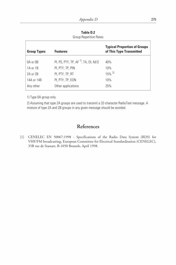
Table D.2Group Repetition Rates
Group Types FeaturesTypical Proportion of Groupsof This Type Transmitted
0A or 0B
1A or 1B
2A or 2B
14A or 14B
Any other
PI, PS, PTY, TP, AF 1), TA, DI, M/S
PI, PTY, TP, PIN
PI, PTY, TP, RT
PI, PTY, TP, EON
Other applications
40%
10%
15% 2)
10%
25%
1) Type 0A group only.
2) Assuming that type 2A groups are used to transmit a 32-character RadioText message. Amixture of type 2A and 2B groups in any given message should be avoided.
References
[1] CENELEC EN 50067:1998 - Specifications of the Radio Data System (RDS) forVHF/FM broadcasting, European Committee for Electrical Standardisation (CENELEC),35B rue de Stassart, B-1050 Brussels, April 1998.
Appendix D 275

Appendix E
Appendix ERDS Data Transmission Capacity Limits
E.1 Introduction
The use of the features to achieve automated tuning, essentially for mobilereception, requires a considerable part of the channel capacity. An RDS uses adata stream of 1187.5 bps and offers a choice of some 20 well-defined features.The data capacity is not large enough to allow all these features to be imple-mented in the same channel, as shown in the following analysis.
E.2 Calculation of RDS Capacity
The bit rate of 1187.5 bps of the RDS is fairly low and therefore the RDSchannel capacity is a rather limited resource. Bearing in mind that the fourcheck words in each group of 104 bits occupy a total of 40 bits, and that eachgroup address needs 5 bits, one arrives at a useful bit rate of
1187.5 − (1187.5/104) × (40 + 5) = 673.7 bps
277
E.3 Analysis of RDS Capacity
E.3.1 Grouping of Different Features
In order to analyse the usage of RDS capacity for each of the features, theyare grouped together in categories according to their impact on the RDSchannel capacity. Firstly, the capacity required for all the broadcastingprogramme-related features is examined and then what is left over for thenonprogramme-related features can be identified.
As is shown in Table E.1, the programme-related features can be dividedinto four categories:
• The five primary features—AF, PI, PS, and TP/TA—mainly requiredfor the automated tuning process;
• The EON information, which really is a complementary feature forautomated tuning as far as networks are concerned;
• A group of features—CT, DI, MS, PIN, PTY, and PTYI—requiringrelatively little RDS capacity to be implemented. Note that PIN onlyrequires a repetition rate of one group type 1A per minute; however, inconnection with RP it must be increased to one per second.
• RadioText.
Furthermore, in Table E.1 the nonprogramme-related features—IH, RP,TDC, and TMC—are identified.
E 3.2 Discussion on the Analysis
The following can be seen from Table E.1:
• AF, PI, PS, TP/TA: These primary functions of RDS, essentially sup-porting the automated tuning process, require already 48.35% of theavailable channel capacity.
• EON: If the automated tuning process were to be enhanced by broad-casters operating networks through the use of the EON feature, 8.24%of the capacity would have to be set aside, bringing the total up to56.59%.
• PTY, MS, DI, PIN, CT: All these features require relatively little RDScapacity. While the first three require 9.65% whether implemented ornot, for reasons of coding, the latter two add an additional 0.21%
278 RDS: The Radio Data System
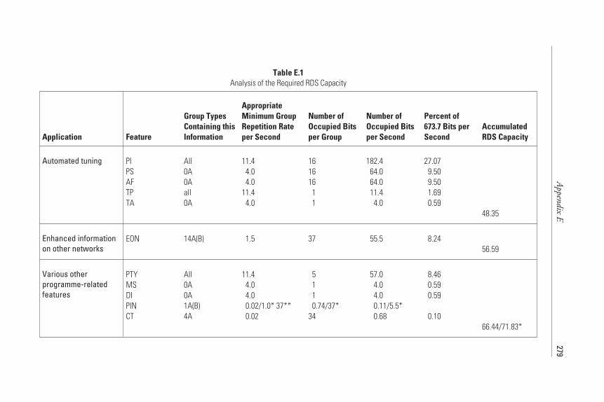
Appendix
E279
Table E.1Analysis of the Required RDS Capacity
Application Feature
Group TypesContaining thisInformation
AppropriateMinimum GroupRepetition Rateper Second
Number ofOccupied Bitsper Group
Number ofOccupied Bitsper Second
Percent of673.7 Bits perSecond
AccumulatedRDS Capacity
Automated tuning PIPSAFTPTA
All0A0Aall0A
11.44.04.0
11.44.0
161616
11
182.464.064.011.4
4.0
27.079.509.501.690.59
48.35
Enhanced informationon other networks
EON 14A(B) 1.5 37 55.5 8.2456.59
Various otherprogramme-relatedfeatures
PTYMSDIPINCT
All0A0A1A(B)4A
11.44.04.00.02/1.0* 37**0.02
5110.74/37*
34
57.04.04.00.11/5.5*0.68
8.460.590.59
0.1066.44/71.83*
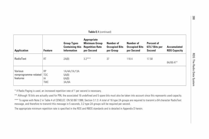
280RDS:The
RadioData
System
Table E.1 (continued)
Application Feature
Group TypesContaining thisInformation
AppropriateMinimum GroupRepetition Rateper Second
Number ofOccupied Bitsper Group
Number ofOccupied Bitsper Second
Percent of673.7 Bits perSecond
AccumulatedRDS Capacity
RadioText RT 2A(B) 3.2*** 37 118.4 17.5884/89.41*
Variousnonprogramme-relatedfeatures
RPTDCIHTMC
1A/4A/7A/13A5A(B)6A(B)3A/8A
* If Radio Paging is used, an increased repetition rate of 1 per second is necessary.
** Although 16 bits are actually used for PIN, the associated 16 undefined and 5 spare bits must also be taken into account since this represents used capacity.
*** To agree with Note 2 in Table 4 of CENELEC EN 50 067:1998, Section 3.1.3: A total of 16 type 2A groups are required to transmit a 64 character RadioTextmessage, and therefore to transmit this message in 5 seconds, 3.2 type 2A groups will be required per second.
The appropriate minimum repetition rate is specified in the RDS and RBDS standards and is detailed in Appendix D herein.

(5.6% if RP is implemented), bringing the total required to 66.44%(or 71.83% with RP).
• RT: RadioText requires an additional 17.58%, bringing the totalrequired for the programme-related features up to 84% (or 89.41%with RP).
This then leaves 16% (10% with RP), for the implementation of thenonprogramme-related features (IH, ODA, TDC, and TMC); that is, 108 bps(or 68 bps with RP). Each of them will require, if implemented, a significantproportion of the remainder. In fact, in the case of Radio Paging, the pagingtraffic is likely to account for the balance of the capacity remaining.
Type A groups, for example, can carry in ODA only up to 37 applicationbits, which means that there will only be capacity left for two to three groupsper second. This makes the dilemma of the very restricted data capacity in RDSfor other than radio programme-related applications very obvious.
However, due to the time-multiplexing possibilities of many of thesefeatures, the average capacity available for other features will be greater thanthis indicated “peak demand,” since it is unlikely, for example, that continuousRadioText will be a requirement.
E.4 Conclusion About RDS Capacity
This form of analysis makes it quite clear that, from the broadcasters’ point ofview, it seems advisable to set aside about 80% of the RDS channel capacity forthe implementation of all programme-related features. This leaves about one-fifth of the channel capacity to accommodate features unrelated to the radiatedprogrammes. This implies that only a limited number of further applicationscan actually be implemented within any specific programme service. Due con-sideration must therefore be given to how IH, ODA, RP, TDC, and TMC canbe distributed among different programme networks; for example, a networkthat carries TP/TA could only accommodate in addition, say, TMC. Thesame is also true with respect to so far unknown applications (e.g., those thatcan be implemented through ODA); their required capacity has to be carefullyexamined before any decision can be taken as to the possibility of theirimplementation.
In conclusion, RDS has a finite capacity—it is not an inexhaustibleresource. That is a fundamental reality that it shares with any other communi-cation channel, including, of course, the VHF/FM broadcast channels thatRDS exploits and serves.
Appendix E 281
References
[1] CENELEC EN 50067:1998 - Specifications of the Radio Data System (RDS) forVHF/FM broadcasting European Committee for Electrical Standardisation (CENELEC),35B rue de Stassart, B-1050 Brussels, April 1998.
[2] EBU, Guidelines for the implementation of the RDS system, Tech. 3260-E, Jan. 1990.
282 RDS: The Radio Data System
Appendix F
Appendix FPI Coding in RDS and RBDS
F.1 Introduction
PI codes are the key to the automatic tuning and follow-me features of a RDS.They act as “digital signatures” to prevent false switching between stations car-rying different programme signals (but perhaps sharing alternate frequencies).Care must be taken, therefore, in the region of borders between different coun-tries, to avoid two stations having the same PI code that are both receivable atthe same location.
Codes shall be assigned in each country in such a way that automaticsearch tuning to other transmitters radiating the same programme can locatethe same PI code; that is, all 16 bits shall be identical. In cases where during afew programme hours, a network is split to radiate different programmes, eachof these programmes shall carry a different PI code, by using differentcoverage-area codes.
PI codes in North America are issued and utilised differently than in therest of the world. The particular principles used are explained in Section F.3.
F.2 Programme Identification Code Structure
The PI code consists of 16 bits and is usually referred to by four hexadecimalcharacters, or nibbles. See Figure F.1 for an example.
283
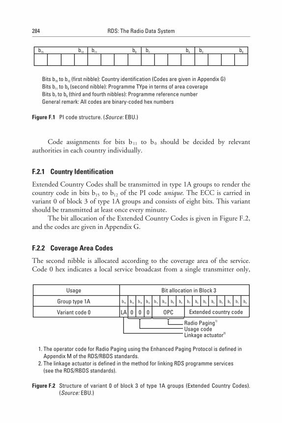
Code assignments for bits b11 to b 0 should be decided by relevantauthorities in each country individually.
F.2.1 Country Identification
Extended Country Codes shall be transmitted in type 1A groups to render thecountry code in bits b15 to b12 of the PI code unique. The ECC is carried invariant 0 of block 3 of type 1A groups and consists of eight bits. This variantshould be transmitted at least once every minute.
The bit allocation of the Extended Country Codes is given in Figure F.2,and the codes are given in Appendix G.
F.2.2 Coverage Area Codes
The second nibble is allocated according to the coverage area of the service.Code 0 hex indicates a local service broadcast from a single transmitter only,
284 RDS: The Radio Data System
b15 b12 b11 b8 b7 b4 b3 b0
Bits b to b (first nibble): Country identification (Codes are given in Appendix G)Bits b to b (second nibble): Programme TYpe in terms of area coverageBits b to b (third and fourth nibbles): Programme reference numberGeneral remark: All codes are binary-coded hex numbers
15 12
11 8
7 0
Figure F.1 PI code structure. (Source: EBU.)
Usage
Group type 1A
Variant code 0
Bit allocation in Block 3
Radio Paging1)
Usage codeLinkage actuator2)
LA OPC Extended country code0 0 0
b0b15 b14 b13 b12 b11 b10 b9 b8 b7 b6 b5 b4 b3 b2 b1
1. The operator code for Radio Paging using the Enhanced Paging Protocol is defined inAppendix M of the RDS/RBDS standards.
2. The linkage actuator is defined in the method for linking RDS programme services(see the RDS/RBDS standards).
Figure F.2 Structure of variant 0 of block 3 of type 1A groups (Extended Country Codes).(Source: EBU.)
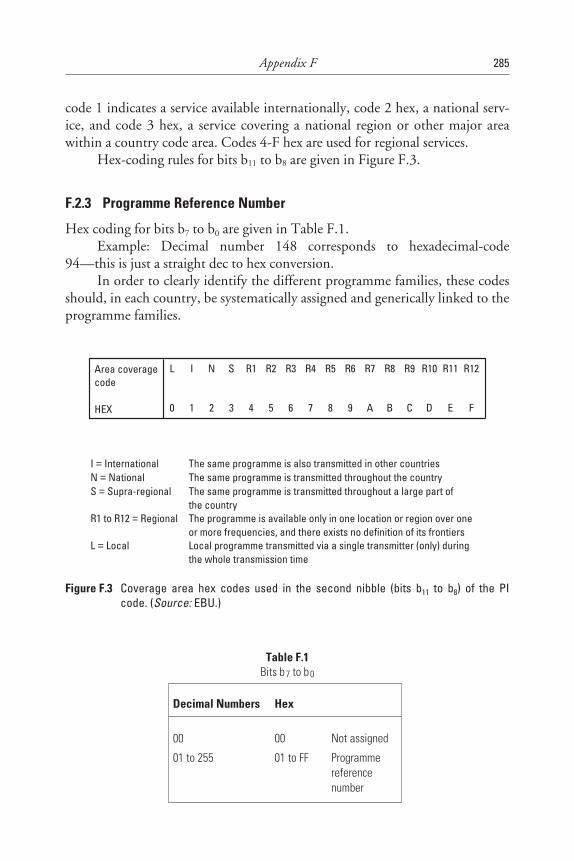
code 1 indicates a service available internationally, code 2 hex, a national serv-ice, and code 3 hex, a service covering a national region or other major areawithin a country code area. Codes 4-F hex are used for regional services.
Hex-coding rules for bits b11 to b8 are given in Figure F.3.
F.2.3 Programme Reference Number
Hex coding for bits b7 to b0 are given in Table F.1.Example: Decimal number 148 corresponds to hexadecimal-code
94—this is just a straight dec to hex conversion.In order to clearly identify the different programme families, these codes
should, in each country, be systematically assigned and generically linked to theprogramme families.
Appendix F 285
Table F.1Bits b 7 to b 0
Decimal Numbers Hex
00 00 Not assigned
01 to 255 01 to FF Programmereferencenumber
Area coveragecode
HEX
L I N S R1 R2 R3 R4 R5 R6 R7 R8 R9 R10 R11 R12
0 1 2 3 4 5 6 7 8 9 A B C D E F
I InternationalN NationalS Supra-regional
R1 to R12 Regional
L Local
===
=
=
The same programme is also transmitted in other countriesThe same programme is transmitted throughout the countryThe same programme is transmitted throughout a large part ofthe countryThe programme is available only in one location or region over oneor more frequencies, and there exists no definition of its frontiersLocal programme transmitted via a single transmitter (only) duringthe whole transmission time
==
=
=
=
Figure F.3 Coverage area hex codes used in the second nibble (bits b11 to b8) of the PIcode. (Source: EBU.)
F.3 PI Coding Rules for North America
F.3.1 Basic Principles
In North America (United States, Canada, and Mexico), PI codes are based oncall letters rather than being assigned by any national organisation, as is donein countries throughout the rest of the world. A portion of the PI codes arereserved for network usage and also for assignment to stations in Canada andMexico.
The CENELEC RDS standard accepts the usage of coverage area codesfor all possible PI codes (see Section F.2 above on coverage area codes). WithinNorth America coverage, area codes are only recognised in the following rangeof PI codes:
• B_01 to B_FF hex
• D_01 to D_FF hex
• E_01 to E_FF hex
All other PI codes do not make use of coverage area codes and must behandled as such within the receiver.
Some current European receivers store PI codes into presets in addition tostoring frequencies into presets. This function is to recognise the broadcast firstby programme rather than frequency. Thus, if a preset is pushed and the PIcode has changed, the European RDS receivers would not recognise the newPI code and go into a PI search.
A technical publication from the EBU states:
If, however, the PI code changes completely, the receiver should initiate aPI search for a frequency whose PI code exactly matches the PI code of theoriginal tuned frequency. Failing an exact PI code match, the receivershould search for a PI code differing only in the regional element (b11 tob8) from the original PI code. If neither of these criterion are met, thereceiver should remain on the original tuned frequency.
Therefore, since call letters are used to create the PI code, the receiverwould have to do a PI search every time a station would change call letters or apreset is pushed in a new listening area having a station at the same frequency as
286 RDS: The Radio Data System
the preset station. For PI codes smaller than B000 hex, future receivers couldcheck the AF list associated with a preset and if no AFs are acceptable, a PIsearch could be initiated. If no identical PI is found, the receiver should returnto the original tuned frequency and accept the new PI code.
If a PI search is performed, the regional variant search (the second searchto match PI codes, differing only in b11 to b8) should be eliminated in a PIsearch if the tuned PI is below B000 hex, or within the ranges of C001 to CFFFhex and F001 to FFFF hex.
If a feature similar to European regional variants is desired, a groupingin the B, D, and E blocks could be designated as follows. If NPR broad-casts break off national programming to go local for a period of time, itcould be assigned a PI of B_01. Note that you cannot use 0 as the secondnibble because current receivers will not search for AFs. Therefore, use 1–8 to Ffor indication of a “regional” variant. If no AFs or identical PIs are foundvia the AF list or an identical PI search, the receiver could, while tuned toNPR station 1 (PI = B101) accept a variant NPR station 2 whose PI variesonly in the second nibble (bits 5–8). Thus B201, B301, B401, … could beaccepted.
PI codes starting with the B, D, and E nibbles yield 765 possibilities for“regional” programming. These PI codes will be shared by the United States,Canada, and Mexico. The problem here becomes that a “telephone book”needs to be kept; however, there should not be too many broadcasts that fit inthis category and not many would be used.
F.3.2 Call Letter Conversion Method
The call letter conversion method to be used is described in detail in theRBDS standard, Annex D, Section 6.1. It makes uses of a conversion tableand some simple algorithms. The details required to make the conversion are,however, so extensive that they cannot be quoted in this book, and only theRBDS standard itself can help here in proceeding with the conversion of aparticular case.
The rules that are spelled out in the RBDS standard could also beimplemented in encoder software so that the station that wants to use RDS cansimply enter its call letters and subsequently the encoder would then make thePI code assignment in full compliance with these rules. The broadcast stationinterested in this matter should discuss this issue with the encoder supplier toavoid any error or misunderstanding.
Appendix F 287

References
[1] CENELEC EN 50067:1998 - Specifications of the Radio Data System (RDS.) forVHF/FM broadcasting European Committee for Electrical Standardisation (CENELEC),35B rue de Stassart, B-1050 Brussels, April 1998.
[2] EIA/NAB(1997), National Radio Systems Committee: United States RBDS Standardversion 2.0, Specification of the Radio Broadcast Data System (RBDS).
[3] EBU, Guidelines for the implementation of the RDS system, Tech. 3260-E, Jan. 1990.
288 RDS: The Radio Data System
Appendix G
Appendix GRDS Country or Area Identification Codes
G.1 Introduction
This appendix lists the RDS country or area identification codes as theyare allocated in the RDS/RBDS standards [1, 2]. Although these standardswere developed for Europe and North America only, the continued develop-ment of RDS worldwide made it necessary to allocate in the RDS/RBDS stan-dards PI country/area identification symbols throughout the world.
The PI code is used in each RDS group, always in the first block of type Aand B groups; for type B groups, the PI code is repeated in the third block.Details of the PI code usage are given in Chapter 3 and Appendix F.
The country/area code is a hex code symbol that occupies the first fourbits of the PI code. Only 15 different symbols exist, and they are repetitivelyassigned to countries in such a way that broadcasts of the one country/areasharing the same symbol cannot be received in the other country/area. How-ever, a unique identification of any country/area sharing the country/area sym-bol with other countries/areas is possible if the optional ECC has also beenimplemented.
It should also be noted that certain countries use more than one coun-try/area symbol. Germany, for example, has two symbols for historical reasons,since the respective codes were allocated before the reunification. Before, onecode was for Eastern Germany and the other for Western Germany, but nowno distinction is being made and both codes may be used all over Germany. Inthe United States, Canada, and Mexico, a range of country/area codes is used to
289

permit application of a formula for the automatic conversion of call letters intothe PI code to avoid the need for any centralised PI administration in thesecountries.
G.2 PI Code Structure
The Programme Identification code consists of 16 bits. Bits b15 to b12 make upthe country/area symbol (hex code) as defined in Section 4. Code assignmentsb11 to b0 should be assigned by relevant authorities in each country or area insuch a way, for example, that bits b11 to b8 describe the Programme TYpe interms of area coverage, and bits b7 to b0 are a programme reference number.
Codes shall always be assigned in such a way that automatic search tuningto other transmitters radiating the same programme can locate the sameProgramme Identification Code; that is, all 16 bits shall be identical.
G.3 Extended Country Codes
ECC shall be transmitted in type 1A groups ( the last eight bits in Block 3 ofVariant 0) to render the country/area code in bits 1 to 4 of the PI code unique.
G.4 Allocated Country/Area Symbols
G.4.1 Allocation of Symbols for Countries in ITU Region 1
G.4.1.1 European Broadcasting AreaTable G.1 lists the PI and ECC symbols for European countries.
290 RDS: The Radio Data System
Table G.1European Codes
Country/Area ISO Code Symbol for PI (Hex) ECC (Hex)
Albania AL 9 E0
Algeria DZ 2 E0
Andorra AD 3 E0

Appendix G 291
Table G.1 (continued)
Country/Area ISO Code Symbol for PI (Hex) ECC (Hex)
Austria AT A E0
Azores [Portugal] PT 8 E4
Belgium BE 6 E0
Belarus BY F E3
Bosnia-Herzegovina BA F E4
Bulgaria BG 8 E1
Canaries [Spain] ES E E2
Croatia HR C E3
Cyprus CY 2 E1
Czech Republic CZ 2 E2
Denmark DK 9 E1
Egypt EG F E0
Estonia EE 2 E4
Faroe Islands [Denmark] DK 9 E1
Finland FI 6 E1
France FR F E1
Germany DE D or 1 E0
Gibraltar [United Kingdom] GI A E1
Greece GR 1 E1
Hungary HU B E0
Iceland IS A E2
Iraq IQ B E1
Ireland IE 2 E3
Israel IL 4 E0
Italy IT 5 E0
Jordan JO 5 E1
Latvia LV 9 E3
Lebanon LB A E3
Libya LY D E1
Liechtenstein LI 9 E2
Lithuania LT C E2
Luxembourg LU 7 E1
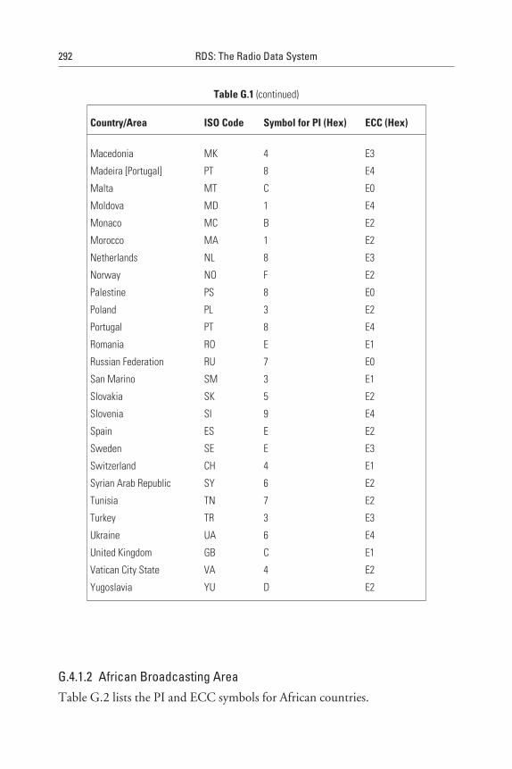
G.4.1.2 African Broadcasting AreaTable G.2 lists the PI and ECC symbols for African countries.
292 RDS: The Radio Data System
Table G.1 (continued)
Country/Area ISO Code Symbol for PI (Hex) ECC (Hex)
Macedonia MK 4 E3
Madeira [Portugal] PT 8 E4
Malta MT C E0
Moldova MD 1 E4
Monaco MC B E2
Morocco MA 1 E2
Netherlands NL 8 E3
Norway NO F E2
Palestine PS 8 E0
Poland PL 3 E2
Portugal PT 8 E4
Romania RO E E1
Russian Federation RU 7 E0
San Marino SM 3 E1
Slovakia SK 5 E2
Slovenia SI 9 E4
Spain ES E E2
Sweden SE E E3
Switzerland CH 4 E1
Syrian Arab Republic SY 6 E2
Tunisia TN 7 E2
Turkey TR 3 E3
Ukraine UA 6 E4
United Kingdom GB C E1
Vatican City State VA 4 E2
Yugoslavia YU D E2
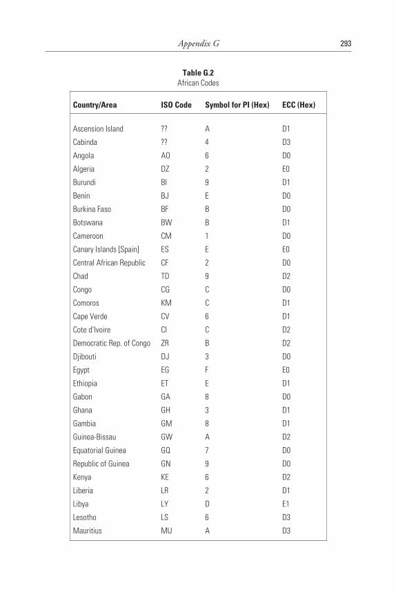
Appendix G 293
Table G.2African Codes
Country/Area ISO Code Symbol for PI (Hex) ECC (Hex)
Ascension Island ?? A D1
Cabinda ?? 4 D3
Angola AO 6 D0
Algeria DZ 2 E0
Burundi BI 9 D1
Benin BJ E D0
Burkina Faso BF B D0
Botswana BW B D1
Cameroon CM 1 D0
Canary Islands [Spain] ES E E0
Central African Republic CF 2 D0
Chad TD 9 D2
Congo CG C D0
Comoros KM C D1
Cape Verde CV 6 D1
Cote d’Ivoire CI C D2
Democratic Rep. of Congo ZR B D2
Djibouti DJ 3 D0
Egypt EG F E0
Ethiopia ET E D1
Gabon GA 8 D0
Ghana GH 3 D1
Gambia GM 8 D1
Guinea-Bissau GW A D2
Equatorial Guinea GQ 7 D0
Republic of Guinea GN 9 D0
Kenya KE 6 D2
Liberia LR 2 D1
Libya LY D E1
Lesotho LS 6 D3
Mauritius MU A D3
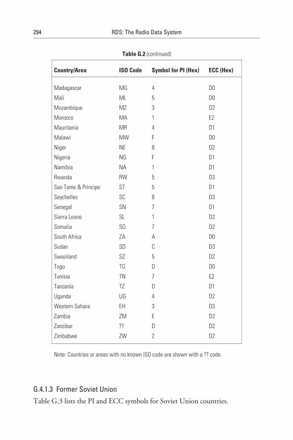
G.4.1.3 Former Soviet UnionTable G.3 lists the PI and ECC symbols for Soviet Union countries.
294 RDS: The Radio Data System
Table G.2 (continued)
Country/Area ISO Code Symbol for PI (Hex) ECC (Hex)
Madagascar MG 4 D0
Mali ML 5 D0
Mozambique MZ 3 D2
Morocco MA 1 E2
Mauritania MR 4 D1
Malawi MW F D0
Niger NE 8 D2
Nigeria NG F D1
Namibia NA 1 D1
Rwanda RW 5 D3
Sao Tome & Principe ST 5 D1
Seychelles SC 8 D3
Senegal SN 7 D1
Sierra Leone SL 1 D2
Somalia SO 7 D2
South Africa ZA A D0
Sudan SD C D3
Swaziland SZ 5 D2
Togo TG D D0
Tunisia TN 7 E2
Tanzania TZ D D1
Uganda UG 4 D2
Western Sahara EH 3 D3
Zambia ZM E D2
Zanzibar ?? D D2
Zimbabwe ZW 2 D2
Note: Countries or areas with no known ISO code are shown with a ?? code.
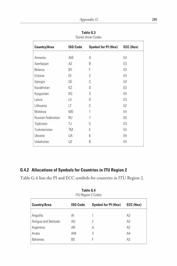
G.4.2 Allocations of Symbols for Countries in ITU Region 2
Table G.4 lists the PI and ECC symbols for countries in ITU Region 2.
Appendix G 295
Table G.3Soviet Union Codes
Country/Area ISO Code Symbol for PI (Hex) ECC (Hex)
Armenia AM A E4
Azerbaijan AZ B E3
Belarus BY F E3
Estonia EE 2 E4
Georgia GE C E4
Kazakhstan KZ D E3
Kyrgyzstan KG 3 E4
Latvia LV 9 E3
Lithuania LT C E2
Moldova MD 1 E4
Russian Federation RU 7 E0
Tajikistan TJ 5 E3
Turkmenistan TM E E4
Ukraine UA 6 E4
Uzbekistan UZ B E4
Table G.4ITU Region 2 Codes
Country/Area ISO Code Symbol for PI (Hex) ECC (Hex)
Anguilla AI 1 A2
Antigua and Barbuda AG 2 A2
Argentina AR A A2
Aruba AW 3 A4
Bahamas BS F A2
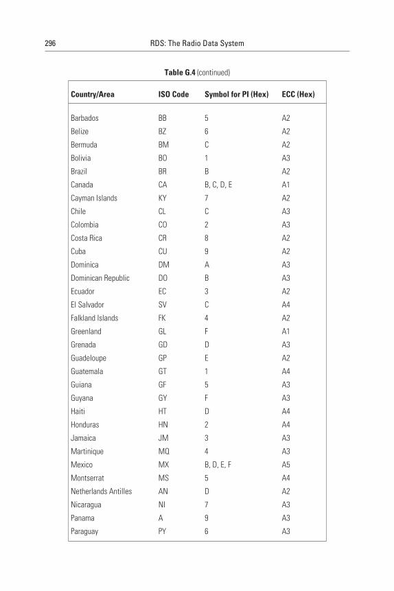
296 RDS: The Radio Data System
Table G.4 (continued)
Country/Area ISO Code Symbol for PI (Hex) ECC (Hex)
Barbados BB 5 A2
Belize BZ 6 A2
Bermuda BM C A2
Bolivia BO 1 A3
Brazil BR B A2
Canada CA B, C, D, E A1
Cayman Islands KY 7 A2
Chile CL C A3
Colombia CO 2 A3
Costa Rica CR 8 A2
Cuba CU 9 A2
Dominica DM A A3
Dominican Republic DO B A3
Ecuador EC 3 A2
El Salvador SV C A4
Falkland Islands FK 4 A2
Greenland GL F A1
Grenada GD D A3
Guadeloupe GP E A2
Guatemala GT 1 A4
Guiana GF 5 A3
Guyana GY F A3
Haiti HT D A4
Honduras HN 2 A4
Jamaica JM 3 A3
Martinique MQ 4 A3
Mexico MX B, D, E, F A5
Montserrat MS 5 A4
Netherlands Antilles AN D A2
Nicaragua NI 7 A3
Panama A 9 A3
Paraguay PY 6 A3
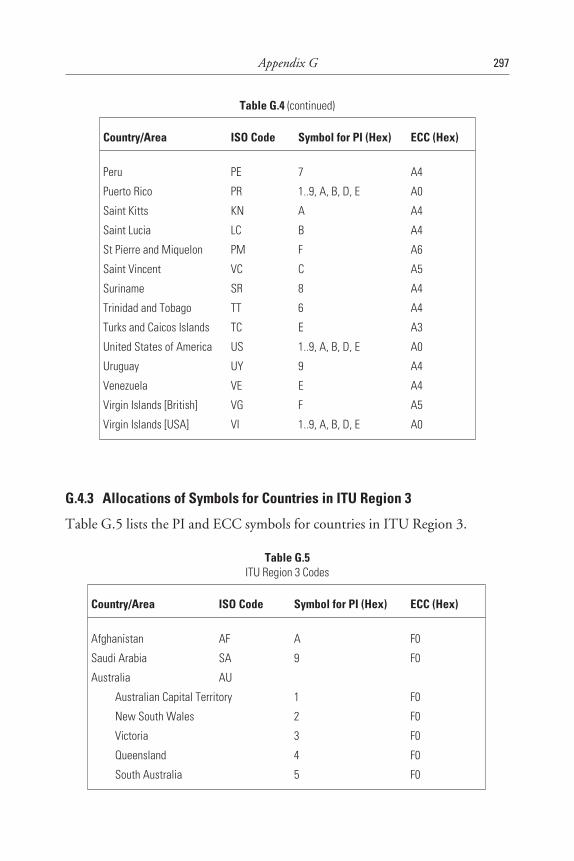
G.4.3 Allocations of Symbols for Countries in ITU Region 3
Table G.5 lists the PI and ECC symbols for countries in ITU Region 3.
Appendix G 297
Table G.4 (continued)
Country/Area ISO Code Symbol for PI (Hex) ECC (Hex)
Peru PE 7 A4
Puerto Rico PR 1..9, A, B, D, E A0
Saint Kitts KN A A4
Saint Lucia LC B A4
St Pierre and Miquelon PM F A6
Saint Vincent VC C A5
Suriname SR 8 A4
Trinidad and Tobago TT 6 A4
Turks and Caicos Islands TC E A3
United States of America US 1..9, A, B, D, E A0
Uruguay UY 9 A4
Venezuela VE E A4
Virgin Islands [British] VG F A5
Virgin Islands [USA] VI 1..9, A, B, D, E A0
Table G.5ITU Region 3 Codes
Country/Area ISO Code Symbol for PI (Hex) ECC (Hex)
Afghanistan AF A F0
Saudi Arabia SA 9 F0
Australia AU
Australian Capital Territory 1 F0
New South Wales 2 F0
Victoria 3 F0
Queensland 4 F0
South Australia 5 F0
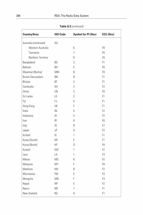
298 RDS: The Radio Data System
Table G.5 (continued)
Country/Area ISO Code Symbol for PI (Hex) ECC (Hex)
Australia (continued) AU
Western Australia 6 F0
Tasmania 7 F0
Northern Territory 8 F0
Bangladesh BD 3 F1
Bahrain BH E F0
Myanmar [Burma] MM B F0
Brunei Darussalam BN B F1
Bhutan BT 2 F1
Cambodia KH 3 F2
China CN C F0
Sri Lanka LK C F1
Fiji FJ 5 F1
Hong Kong HK F F1
India IN 5 F2
Indonesia ID C F2
Iran IR 8 F0
Iraq IQ B E1
Japan JP 9 F2
Kiribati KI 1 F1
Korea [South] KR E F1
Korea [North] KP D F0
Kuwait KW 1 F2
Laos LA 1 F3
Macau MO 6 F2
Malaysia MY F F0
Maldives MV B F2
Micronesia FM E F3
Mongolia MN F F3
Nepal NP E F2
Nauru NR 7 F1
New Zealand NZ 9 F1
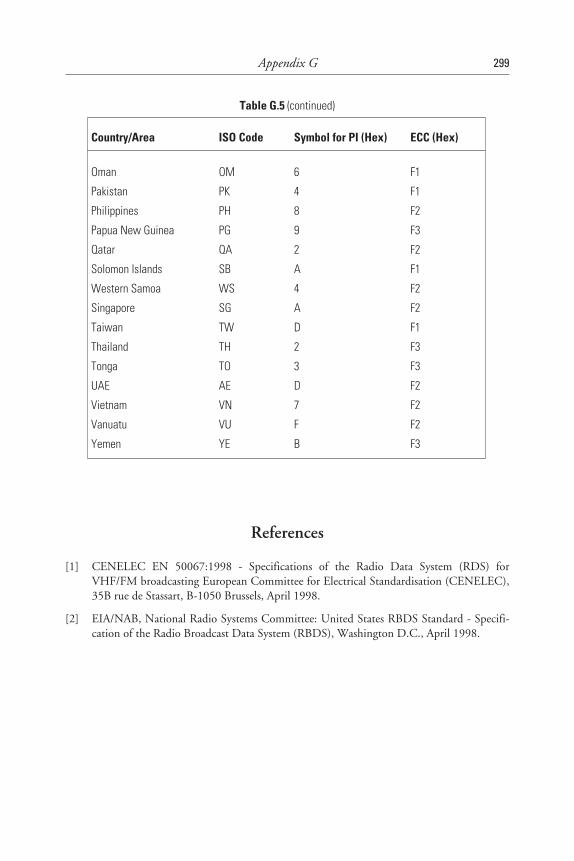
References
[1] CENELEC EN 50067:1998 - Specifications of the Radio Data System (RDS) forVHF/FM broadcasting European Committee for Electrical Standardisation (CENELEC),35B rue de Stassart, B-1050 Brussels, April 1998.
[2] EIA/NAB, National Radio Systems Committee: United States RBDS Standard - Specifi-cation of the Radio Broadcast Data System (RBDS), Washington D.C., April 1998.
Appendix G 299
Table G.5 (continued)
Country/Area ISO Code Symbol for PI (Hex) ECC (Hex)
Oman OM 6 F1
Pakistan PK 4 F1
Philippines PH 8 F2
Papua New Guinea PG 9 F3
Qatar QA 2 F2
Solomon Islands SB A F1
Western Samoa WS 4 F2
Singapore SG A F2
Taiwan TW D F1
Thailand TH 2 F3
Tonga TO 3 F3
UAE AE D F2
Vietnam VN 7 F2
Vanuatu VU F F2
Yemen YE B F3
Appendix H
Appendix HPTY Display Terms in Several DifferentLanguages
H.1 Introduction
This Appendix gives details for the following languages: English, French,German, Spanish and Swedish.
Each of the following tables have a listing of the PTY codes fromEN50067:1998 Annex F, showing the number, English language ProgrammeTYpe and then a corresponding term (and not necessarily the literally trans-lated one) of the other appropriate language, followed by their 8-character and16-character display terms which may be used.
The listings in the different languages given here, were agreed uponwithin the RDS Forum. Corresponding terms for other languages can befound, when agreed, on the RDS Forum Web site, URL: www.rds.org.uk/.
It is very important to note, that “LARGE LETTERS” (upper case) and“small letters” (lower case) are used and that “spaces” are clearly shown usingthe “_” notation. Not all receivers can display both “LARGE LETTERS” and“small letters,” but they are specified, so that receivers which do display themcan benefit from the enhanced readability of their use.
301
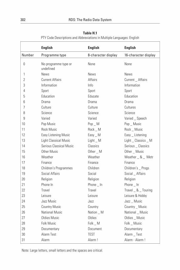
Table H.1PTY Code Descriptions and Abbreviations in Multiple Languages: English
English English English
Number Programme type 8-character display 16-character display
0 No programme type orundefined
None None
1 News News News2 Current Affairs Affairs Current _ Affairs3 Information Info Information4 Sport Sport Sport5 Education Educate Education6 Drama Drama Drama7 Culture Culture Cultures8 Science Science Science9 Varied Varied Varied _ Speech
10 Pop Music Pop _ M Pop _ Music11 Rock Music Rock _ M Rock _ Music12 Easy Listening Music Easy _ M Easy _ Listening13 Light Classical Music Light _ M Light _ Classics _ M14 Serious Classical Music Classics Serious _ Classics15 Other Music Other _ M Other _ Music16 Weather Weather Weather _ & _ Metr17 Finance Finance Finance18 Children’s Programmes Children Children’s _ Progs19 Social Affairs Social Social _ Affairs20 Religion Religion Religion21 Phone In Phone _ In Phone _ In22 Travel Travel Travel _ & _ Touring23 Leisure Leisure Leisure & Hobby24 Jazz Music Jazz Jazz _ Music25 Country Music Country Country _ Music26 National Music Nation _ M National _ Music27 Oldies Music Oldies Oldies _ Music28 Folk Music Folk _ M Folk _ Music29 Documentary Document Documentary30 Alarm Test TEST Alarm _ Test31 Alarm Alarm ! Alarm - Alarm !
Note: Large letters, small letters and the spaces are critical.
302 RDS: The Radio Data System

Table H.2PTY Code Descriptions and Abbreviations in Multiple Languages: French
English French French French
Num-ber
Programme type Programme type 8-characterdisplay
16-characterdisplay
0 No programme type orundefined
Codification de programme nonutilisée ou genre non défini
Aucun Non défini
1 News Informations Infos Informations2 Current Affairs Magazine Magazine Magazine3 Information Info-Service Services Info-Service4 Sport Sport Sport Sport5 Education Education Educatif Educatif6 Drama Dramatique Fiction Fiction7 Culture Culture Culture Culture8 Science Sciences Sciences Sciences9 Varied Divertissement Divers Divertissement
10 Pop Music Pop M _ Pop Musique _ Pop11 Rock Music Rock M _ Rock Musique _ Rock12 Easy Listening Music Chansons Chansons Chansons13 Light Classical Music Classique Léger M _ Cl _ Lég Classique _ Léger14 Serious Classical Music Musique Classique Classiq MusiqueClassique15 Other Music Autre Musique Autre _ M Autre _ Musique16 Weather Météo Météo Météo17 Finance Economie et Finances Economie Economie18 Children’s Programmes Programmes pour enfants Enfants Enfants19 Social Affairs Société Société Société20 Religion Religion Religion Religion21 Phone In Ligne ouverte et interactivité Forum Ligne _ ouverte22 Travel Voyages Voyages Voyages23 Leisure Loisirs Loisirs Loisirs24 Jazz Music Musique de jazz Jazz Jazz25 Country Music Musique de country Country Country26 National Music Chansons du pays Ch _ pays Chanson _ du _ pays27 Oldies Music Musique rétro Rétro Musique _ rétro28 Folk Music Musique folklorique Folklore Folklore29 Documentary Documentaire Document Documentaire30 Alarm Test Test d’alarme TEST TEST31 Alarm Alerte Alerte _ ! Alerte _ !
Note: Large letters, small letters and the spaces are critical.
Appendix H 303
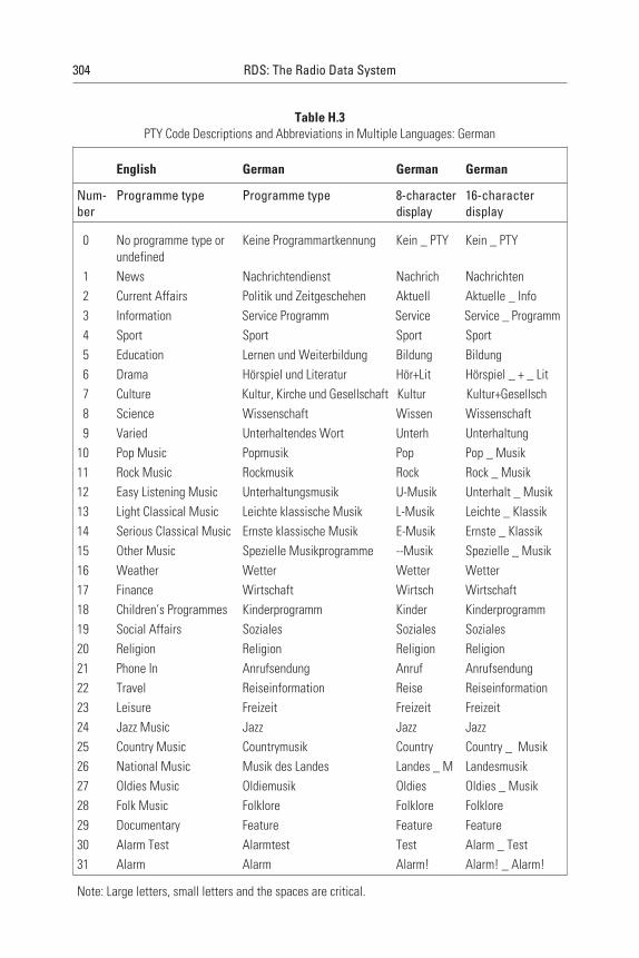
Table H.3PTY Code Descriptions and Abbreviations in Multiple Languages: German
English German German German
Num-ber
Programme type Programme type 8-characterdisplay
16-characterdisplay
0 No programme type orundefined
Keine Programmartkennung Kein _ PTY Kein _ PTY
1 News Nachrichtendienst Nachrich Nachrichten2 Current Affairs Politik und Zeitgeschehen Aktuell Aktuelle _ Info3 Information Service Programm Service Service _ Programm4 Sport Sport Sport Sport5 Education Lernen und Weiterbildung Bildung Bildung6 Drama Hörspiel und Literatur Hör+Lit Hörspiel _ + _ Lit7 Culture Kultur, Kirche und Gesellschaft Kultur Kultur+Gesellsch8 Science Wissenschaft Wissen Wissenschaft9 Varied Unterhaltendes Wort Unterh Unterhaltung
10 Pop Music Popmusik Pop Pop _ Musik11 Rock Music Rockmusik Rock Rock _ Musik12 Easy Listening Music Unterhaltungsmusik U-Musik Unterhalt _ Musik13 Light Classical Music Leichte klassische Musik L-Musik Leichte _ Klassik14 Serious Classical Music Ernste klassische Musik E-Musik Ernste _ Klassik15 Other Music Spezielle Musikprogramme --Musik Spezielle _ Musik16 Weather Wetter Wetter Wetter17 Finance Wirtschaft Wirtsch Wirtschaft18 Children’s Programmes Kinderprogramm Kinder Kinderprogramm19 Social Affairs Soziales Soziales Soziales20 Religion Religion Religion Religion21 Phone In Anrufsendung Anruf Anrufsendung22 Travel Reiseinformation Reise Reiseinformation23 Leisure Freizeit Freizeit Freizeit24 Jazz Music Jazz Jazz Jazz25 Country Music Countrymusik Country Country _ Musik26 National Music Musik des Landes Landes _ M Landesmusik27 Oldies Music Oldiemusik Oldies Oldies _ Musik28 Folk Music Folklore Folklore Folklore29 Documentary Feature Feature Feature30 Alarm Test Alarmtest Test Alarm _ Test31 Alarm Alarm Alarm! Alarm! _ Alarm!
Note: Large letters, small letters and the spaces are critical.
304 RDS: The Radio Data System
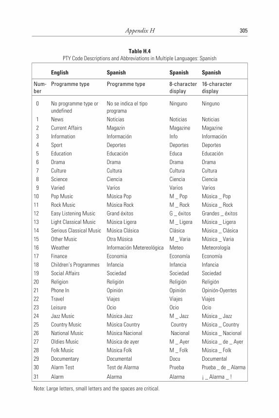
Table H.4PTY Code Descriptions and Abbreviations in Multiple Languages: Spanish
English Spanish Spanish Spanish
Num-ber
Programme type Programme type 8-characterdisplay
16-characterdisplay
0 No programme type orundefined
No se indica el tipoprograma
Ninguno Ninguno
1 News Noticias Noticias Noticias2 Current Affairs Magazin Magazine Magazine3 Information Información Info Información4 Sport Deportes Deportes Deportes5 Education Educación Educa Educación6 Drama Drama Drama Drama7 Culture Cultura Cultura Cultura8 Science Ciencia Ciencia Ciencia9 Varied Varios Varios Varios
10 Pop Music Música Pop M _ Pop Música _ Pop11 Rock Music Música Rock M _ Rock Música _ Rock12 Easy Listening Music Grand éxitos G _ éxitos Grandes _ éxitos13 Light Classical Music Música Ligera M _ Ligera Música _ Ligera14 Serious Classical Music Música Clásica Clásica Música _ Clásica15 Other Music Otra Música M _ Varia Música _ Varia16 Weather Información Metereológica Meteo Meteorología17 Finance Economia Economía Economía18 Children’s Programmes Infancia Infancia Infancia19 Social Affairs Sociedad Sociedad Sociedad20 Religion Religión Religión Religión21 Phone In Opinión Opinión Opinión-Oyentes22 Travel Viajes Viajes Viajes23 Leisure Ocio Ocio Ocio24 Jazz Music Música Jazz M _ Jazz Música _ Jazz25 Country Music Música Country Country Música _ Country26 National Music Música Nacional Nacional Música _ Nacional27 Oldies Music Música de ayer M _ Ayer Música _ de _ Ayer28 Folk Music Música Folk M _ Folk Música _ Folk29 Documentary Documental Docu Documental30 Alarm Test Test de Alarma Prueba Prueba _ de _ Alarma
31 Alarm Alarma Alarma ¡ _ Alarma _ !
Note: Large letters, small letters and the spaces are critical.
Appendix H 305
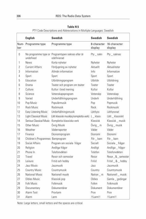
Table H.5PTY Code Descriptions and Abbreviations in Multiple Languages: Swedish
English Swedish Swedish Swedish
Num-ber
Programme type Programme type 8-characterdisplay
16-characterdisplay
0 No programme type orundefined
Programtypen saknas eller ärodefinierad
Pty _ sakn Pty _ saknas
1 News Korta nyheter Nyheter Nyheter2 Current Affairs Fördjupning av nyheter Aktuellt Aktualiteter3 Information Allmän information Info Information4 Sport Sport Sport Sport5 Education Utbildningsprogram Utbildn Utbildning6 Drama Teater och program om teater Teater Teater7 Culture Kultur i bred mening Kultur Kultur8 Science Vetenskapsprogram Vetenskp Vetenskap9 Varied Underhållningsprogram Underh Underhållning
10 Pop Music Populärmusik Pop Popmusik11 Rock Music Rockmusik Rock Rockmusik12 Easy Listening Music Underhållningsmusik Lättlyss Lättlyssnat13 Light Classical Music Lätt klassisk musik(ej kompletta verk) L _ klass Lätt _ klassiskt14 Serious Classical Music Kompletta klassiska verk Klassisk Klassisk _ musik15 Other Music Övrig Musik Övrig _ m Övrig _ musik16 Weather Väderraporter Väder Väder17 Finance Ekonomiprogram Ekonomi Ekonomi18 Children’s Programmes Barnprogram För _ barn För _ barn19 Social Affairs Program om sociala frågor Socialt Sociala _ frågor20 Religion Andliga frågor Andligt Andliga _ frågor21 Phone In Telefonväkteri Telefon Telefonväkteri22 Travel Resor och semester Resor Resor_&_semester23 Leisure Fritid och hobby Fritid Fritid _ & _ hobby24 Jazz Music Jazzmusik Jazz Jazzmusik25 Country Music Countrymusik Country Countrymusik26 National Music Nationell musik Nation _ m Nationell _ musik27 Oldies Music Klassisk pop Oldies Gamla _ godingar28 Folk Music Folkmusik Folkm Folkmusik29 Documentary Dokumentärer Dokument Dokumentärer30 Alarm Test Provlarm Prov Prov31 Alarm Larm !!Larm!! !!Larm!!
Note: Large letters, small letters and the spaces are critical.
306 RDS: The Radio Data System

References
[1] PTY display terms in several different languages, RDS Forum Document 98/009,Sept. 1998
Appendix H 307
Appendix I
Appendix ICharacter Sets for Alphanumeric Display
Three different alphanumeric character repertoires have been defined inAnnex E of the RDS/RBDS standards; they are reproduced in Figures E.1 toE.3. Taken together, they permit the composition of texts indicating the nameof the programme service and the constitution of radio data messages (e.g.,RadioText) or alphanumeric paging calls. The three code tables were designedby the EBU. They contain almost all the characters in the international refer-ence version of ISO Publication 6461. The same codes have been given to eachof these characters in all three tables. Care has been taken in the design of thecoding tables to ensure that it will be possible to satisfy all the requirementswithin large geographical areas with each repertoire, and it is therefore likelythat some receivers will be equipped to display only the characters included inone of the three repertoires. Up until 1997/98, RDS receivers have used onlyFigure I.1, or even only parts of it. Nonetheless, it is necessary to provide infor-mation identifying the repertoire in use in order to ensure that the display cor-responds as closely as possible to the intentions of the broadcasting organisationwhen received on a receiver able to display characters from more than one
309
1. Including the figures 0 to 9 and punctuation; nonetheless, in certain cases, codes have beenre-allocated to characters taken from the EBU repertoires, in accordance with the provisionof ISO Publication 646.
repertoire. Since the default code table is Figure I.1, this indication is onlyrequired if one of the other two code tables is used or if one changes from oneof them back to code table 1.
The repertoire tables were designed by the EBU with the view of coveringthe requirements satisfying the use of languages within the European broad-casting area. However, a compromise had to be made to keep these tables smallin size. As a consequence of this, one or the other character from a particularlanguage was left out, because it could be replaced by another. For example, inGreek, small theta, should be substituted by a capital theta.
In accordance with the practice in the videotext service, where more thanone character repertoire is defined also, control codes have been allocated todistinguish between the basic (Figure I.1) and two auxiliary (see Annex E of theRDS/RBDS standards) code tables. The selection of the required code table iscontrolled by the transmission of the corresponding repertoire control charac-ters—SI (0/15), SO (0/14), and LS2 (1/11 followed by 6/14)2. In radio data, itis controlled by the transmission of one of the following pairs of repertoire con-trol characters:
• 0/15, 0/15—code table of Figure I.1;
• 0/14, 0/14—code table of Figure E.2 in Annex E of the RDS/RBDSstandards;
• 1/11, 6/14—code table of Figure E.3 in Annex E of the RDS/RBDSstandards.
These characters do not occupy a space in the display, but have effect onthe displayable characters having the same address, and on all characters havingnumerically higher addresses up to but not including the address of anotherrepertoire control character. In default of a repertoire control character, thedisplay coding taking effect at address 0 should be assumed to be in accor-dance with the default code table given in Figure I.1. For example, the name“Radio 1” could be transmitted in type 0 groups as follows:
Characters: Ra di oSP 1SP
Text segment address: 0 1 2 3
310 RDS: The Radio Data System
2. The notation A/B is used to designate the character appearing in column A on line B in thetable.
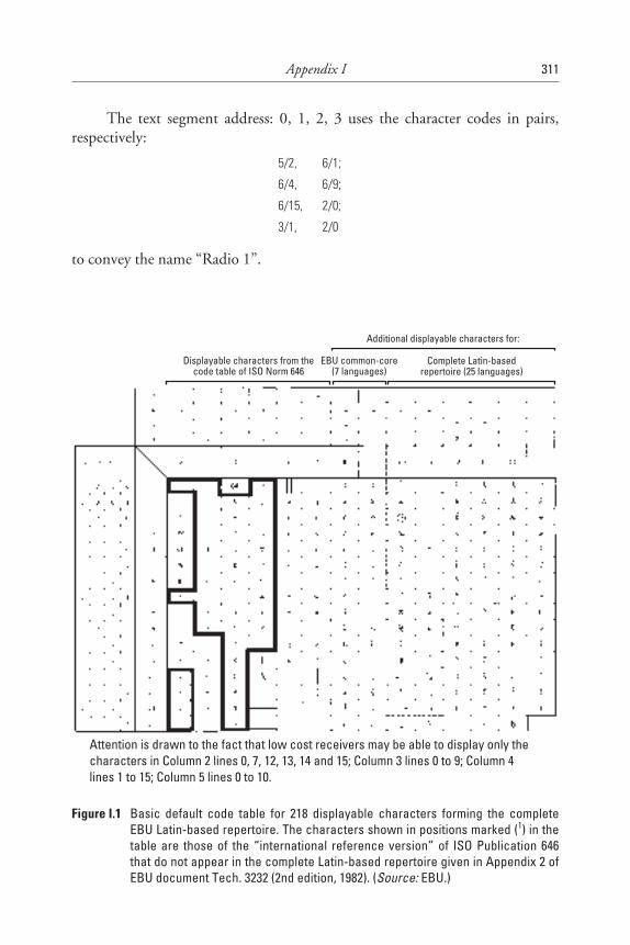
The text segment address: 0, 1, 2, 3 uses the character codes in pairs,respectively:
5/2, 6/1;
6/4, 6/9;
6/15, 2/0;
3/1, 2/0
to convey the name “Radio 1”.
Appendix I 311
Displayable characters from thecode table of ISO Norm 646
EBU common-core(7 languages)
Complete Latin-basedrepertoire (25 languages)
Additional displayable characters for:
Attention is drawn to the fact that low cost receivers may be able to display only thecharacters in Column 2 lines 0, 7, 12, 13, 14 and 15; Column 3 lines 0 to 9; Column 4lines 1 to 15; Column 5 lines 0 to 10.
Figure I.1 Basic default code table for 218 displayable characters forming the completeEBU Latin-based repertoire. The characters shown in positions marked (1) in thetable are those of the “international reference version” of ISO Publication 646that do not appear in the complete Latin-based repertoire given in Appendix 2 ofEBU document Tech. 3232 (2nd edition, 1982). (Source: EBU.)
References
[1] CENELEC EN 50067:1998 - Specifications of the Radio Data System (RDS) forVHF/FM broadcasting, European Committee for Electrical Standardisation (CENELEC),35B rue de Stassart, B-1050 Brussels, April 1998.
[2] EIA/NAB(1997) - National Radio Systems Committee: United States RBDS StandardVersion 2.0, Specification of the Radio Broadcast Data System (RBDS).
312 RDS: The Radio Data System
Appendix J
Appendix JImplemented RDS Features in VariousCountries
J.1 Introduction
When broadcasters or transmission operators implement RDS, it is relativelyeasy to implement the static RDS features such as PI, PS, and AF, because astand-alone RDS encoder at a transmitter site can be used. But programme-related RDS features require a data link from the studio to the RDS encoder,which may be inexpensive for just one single transmitter but quite expensivewhen the radio programme is going over a network of transmitters. An addi-tional complexity exists when the network is split during certain hours of theday for regionalised programming. This is one of the main reasons why somemajor broadcast networks have not yet fully implemented the dynamicprogramme-related RDS features. Another reason is, of course, related to thefact that the production of radio programme-dependent RDS data requiresadditional human resources, and there is still some reluctance to invest in thisactivity given the fact that the number of receivers that support the dynamicRDS programme-related features (and specifically RadioText) is still relativelysmall in relation to the total number of receivers that are in use. This situationis, however, slowly changing because new RDS receivers tend to increasinglysupport dynamic programme-related RDS features.
The RDS Forum has for many years published a list of RDS featuresimplemented in various countries. The following provides a summary that isderived from the data published in that list.
313
Almost all operators use a subcarrier injection level of ±2 kHz. When thislevel is different, this fact is mentioned below.
Austria: ORF uses, in addition to the static RDS features, TP/TA andEON. RT is only tested, and not really implemented. CT is not used. PTY andtraffic message channel TMC are being considered.
Belgium: VRT and RTBF use in addition to the static RDS features alsoTP/TA and EON. Only VRT uses PTY and RT. All these programmes useCT. TMC is being considered, and RTBF will start operation in late 1998.
Brazil: Interest is increasing and initial services are starting on severalradio stations in Rio de Janeiro and São Paulo.
Croatia: Croatian radio uses in addition to the static RDS features alsoTP/TA and EON. CT is implemented and so is RP using an injection level of±4 kHz.
Denmark: DR uses, in addition to the static RDS features, TP/TA andEON. CT is implemented, but not PTY. RadioText is only tested, and notreally implemented. TMC and DGPS will be implemented during 1998.
Finland: YLE uses almost all RDS features except MS. However PTY,PIN, and RT are only on two of their five networks. RP is used on two net-works that use the higher injection level of ±4 kHz.
France: Radio France uses, in addition to the static RDS features, TP/TAand EON. RT is used only in Paris on FIP. TMC is used in Paris and isplanned for use by the motorway radio programme for 1998/99. RP is used onprogrammes of Radio France. The injection level in use is ±4 kHz. Severalcommercial radio stations use TP, but they do not switch TA. CT is generallyimplemented on all stations. MS, PTY, and PIN are not yet used.
Germany: The public broadcasters use almost all RDS features, but manyof them are only implemented partially. CT is sometimes not correctly imple-mented. PIN is not used. TMC was implemented in 1997 and for DGPS theRASANT system will be used nationwide. RP is partially used. Private broad-casters use (sometimes wrongly) dynamic PS. Several programmes useprogramme-related RadioText.
Greece: ERT uses CT and RT in addition to the static RDS features, butnot EON. Private broadcasters often wrongly use dynamic PS.
Hong Kong: RTHK uses only the static RDS features and is testing TP,TA, PTY, and RT.
Hungary: Some programmes use the static RDS features, RT, and RPwith an injection level of ±4 kHz.
Ireland: RTE uses mainly static RDS features, but also PIN and EON.PTY and RT are planned. RP is used by RTE for its own staff, the injectionlevel being ±2.5 kHz. Their other networks use a deviation of ±2.2 kHz.
314 RDS: The Radio Data System

Italy: RAI mainly uses the static RDS features and is testing the otherones. CT is not used. TMC is being tested in Northern Italy, starting fromBologna. Private radio stations use dynamic PS wrongly. Many of these use fre-quencies that are “offset” by 50 kHz.
Luxembourg: RTL uses mainly the static RDS features and CT. DGPS isbeing tested.
Netherlands: Radio programmes use the static RDS features and CT. RTis frequently implemented. Not used are PTY, PIN, and MS. RP and DGPSare partially used. A regular TMC service starts in the spring of 1998 on Radio3. Some commercial radio stations wrongly use dynamic PS.
Norway: NRK programmes uses the static RDS features, EON, CT, andRT. Local radios use also RT. The DGPS is being tested.
Portugal: Most radio stations use the static RDS features. RDP plans tostart TMC in Lisbon in 1998.
Slovenia: Radio Slovenia uses, in addition to the static RDS features,TP/TA and EON. CT is implemented and so is RP, using an injection level of±4 kHz.
South Africa: SABC uses only the static RDS features and EON. RP isbeing tested.
Spain: RNE uses almost all RDS features. TMC will be implemented inMadrid and on the motorway to Barcelona and France. Private networks usemainly the static RDS features. PTY is used by some networks.
Sweden: SR has implemented all RDS features. Teracom operates DGPSand the Swedish Road Authority uses TMC nationwide. RP was in use formany years and has been closed down. Injection levels are either ±2.5 or3.0 kHz. Local radio stations use mainly the static RDS features and some testRT. Some private radio stations wrongly use dynamic PS.
Switzerland: SRG/SSR mostly use the static RDS features and EON.DGPS and TMC are planned. Some private stations wrongly use dynamic PS.
United Kingdom: BBC has implemented most RDS features except MS.Classic FM has implemented the static RDS features and RT. Furthermore,DGPS is implemented under the Additional Services Licence and on the sametransmitters. TMC will be implemented in 1998. PTY and CT are also used onmany independent radio stations.
United States: Radio stations are increasingly interested in using RDS,and in all metropolitan areas, several local radio stations now offer RDS, usu-ally implemented with static features. There is much interest in programme-related features, with trials of RT and PTY in progress.
Appendix J 315
Appendix K
Appendix KWeb Site of the RDS Forum
The Web site of the RDS Forum provides many necessary references andup-to-date information for users of the RDS technology. It also offers the possi-bility to join the RDS Forum. The structure of the Web site is as outlined inFigure K.1.
317
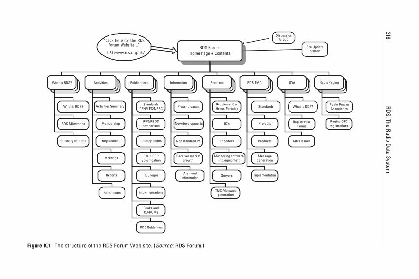
318RDS:The
RadioData
System
RDS ForumHome Page + Contents
What is RDS?
"Click here for the RDSForum Website..."
URL:www.rds.org.uk/
What is RDS?
RDS Milestones
Glossary of terms
Information
Press releases
New developments
Non standard PS
Receiver marketgrowth
Archivedinformation
Radio Paging
Radio PagingAssociation
Paging OPCregistrations
RDS-TMC
Standards
Projects
Products
Messagegeneration
Implementation
ODA
What is ODA?
RegistrationForms
Activities
Activities Summary
Membership
Registration
Meetings
Reports
Resolutions
Publications
StandardsCENELEC/NRSC
RDS/RBDScomparison
Country codes
EBU UECPSpecification
RDS logos
Books andCD-ROMs
Implementations
RDS Guidelines
Products
Receivers: Car,Home, Portable
IC's
Encoders
Monitoring softwareand equipment
Servers
TMC Messagegeneration
AIDs Issued
DiscussionGroup
Site Updatehistory
Figure K.1 The structure of the RDS Forum Web site. (Source: RDS Forum.)
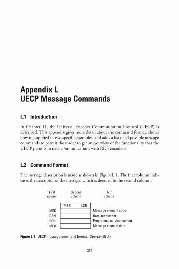
Appendix L
Appendix LUECP Message Commands
L.1 Introduction
In Chapter 11, the Universal Encoder Communication Protocol (UECP) isdescribed. This appendix gives more detail about the command format, showshow it is applied in two specific examples, and adds a list of all possible messagecommands to permit the reader to get an overview of the functionality that theUECP permits in data communications with RDS encoders.
L.2 Command Format
The message description is made as shown in Figure L.1. The first column indi-cates the descriptor of the message, which is detailed in the second column.
319
Firstcolumn
Secondcolumn
Thirdcolumn
MSB LSBMEC Message element codeDSN Data set numberPSN Programme service numberMED Message element data
Figure L.1 UECP message command format. (Source: EBU.)
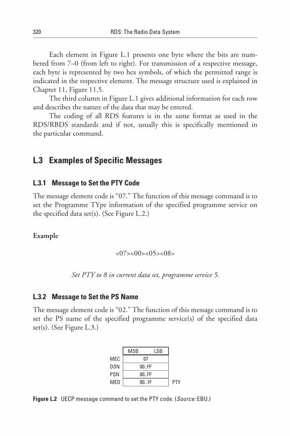
Each element in Figure L.1 presents one byte where the bits are num-bered from 7–0 (from left to right). For transmission of a respective message,each byte is represented by two hex symbols, of which the permitted range isindicated in the respective element. The message structure used is explained inChapter 11, Figure 11.5.
The third column in Figure L.1 gives additional information for each rowand describes the nature of the data that may be entered.
The coding of all RDS features is in the same format as used in theRDS/RBDS standards and if not, usually this is specifically mentioned inthe particular command.
L.3 Examples of Specific Messages
L.3.1 Message to Set the PTY Code
The message element code is “07.” The function of this message command is toset the Programme TYpe information of the specified programme service onthe specified data set(s). (See Figure L.2.)
Example
<07><00><05><08>
Set PTY to 8 in current data set, programme service 5.
L.3.2 Message to Set the PS Name
The message element code is “02.” The function of this message command is toset the PS name of the specified programme service(s) of the specified dataset(s). (See Figure L.3.)
320 RDS: The Radio Data System
MSB LSB07
00..FF00..FF00..1F PTY
MECDSNPSNMED
Figure L.2 UECP message command to set the PTY code. (Source: EBU.)
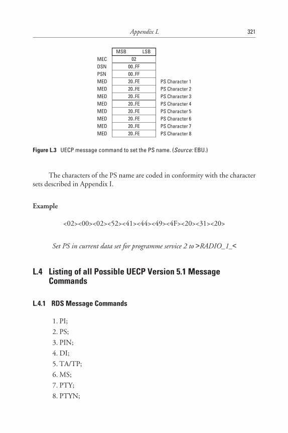
The characters of the PS name are coded in conformity with the charactersets described in Appendix I.
Example
<02><00><02><52><41><44><49><4F><20><31><20>
Set PS in current data set for programme service 2 to >RADIO_1_<
L.4 Listing of all Possible UECP Version 5.1 MessageCommands
L.4.1 RDS Message Commands
1. PI;
2. PS;
3. PIN;
4. DI;
5. TA/TP;
6. MS;
7. PTY;
8. PTYN;
Appendix L 321
MSB LSB02
00..FF00..FF20..FE20..FE20..FE20..FE20..FE20..FE20..FE20..FE
MECDSNPSNMEDMEDMEDMEDMEDMEDMEDMED
PS Character 1PS Character 2PS Character 3PS Character 4PS Character 5PS Character 6PS Character 7PS Character 8
Figure L.3 UECP message command to set the PS name. (Source: EBU.)
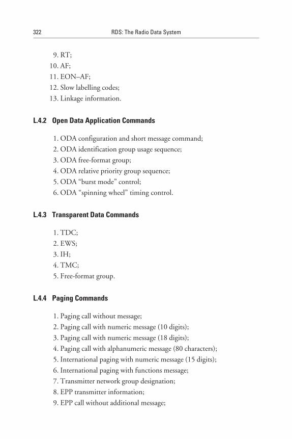
9. RT;
10. AF;
11. EON–AF;
12. Slow labelling codes;
13. Linkage information.
L.4.2 Open Data Application Commands
1. ODA configuration and short message command;
2. ODA identification group usage sequence;
3. ODA free-format group;
4. ODA relative priority group sequence;
5. ODA “burst mode” control;
6. ODA “spinning wheel” timing control.
L.4.3 Transparent Data Commands
1. TDC;
2. EWS;
3. IH;
4. TMC;
5. Free-format group.
L.4.4 Paging Commands
1. Paging call without message;
2. Paging call with numeric message (10 digits);
3. Paging call with numeric message (18 digits);
4. Paging call with alphanumeric message (80 characters);
5. International paging with numeric message (15 digits);
6. International paging with functions message;
7. Transmitter network group designation;
8. EPP transmitter information;
9. EPP call without additional message;
322 RDS: The Radio Data System

10. EPP national and international call with alphanumeric message;
11. EPP national and international call with variable-length numericmessage;
12. EPP national and international call with variable-length functionsmessage.
L.4.5 Clock Setting and Control
1. Real-time clock;
2. Real-time clock correction;
3. CT On/Off.
L.4.6 RDS Adjustment and Control
1. RDS On/Off;
2. RDS phase;
3. RDS level.
L.4.7 ARI Adjustment and Control
1. ARI On/Off;
2. ARI area;
3. ARI level.
L.4.8 Control and Setup Commands
1. Site address.
2. Encoder address;
3. Make PSN list;
4. PSN enable/disable;
5. Communication mode;
6. TA control;
7. EON-TA control;
8. Reference input select;
9. Data set select;
Appendix L 323
10. Group sequence;
11. Group variant code sequence;
12. Extended group sequence;
13. PS character code table selection;
14. Encoder access right;
15. Communications port mode configuration;
16. Communications port speed configuration;
17. Communications port timeout configuration.
L.4.9 Bidirectional Commands (Remote and Configuration Commands)
1. Message acknowledgement;
2. Request message.
L.4.10 Specific Message Commands
1. Manufacturer’s specific command.
References
[1] EBU, Universal Encoder Communications Protocol UECP-version 5.1, European Broad-casting Union, 17A, Ancienne Route, CH-1218 Geneva, Switzerland Aug. 1997.
324 RDS: The Radio Data System
Appendix M
Appendix MGlossary and Abbreviations
M.1 Glossary
This glossary provides brief descriptions of the RDS features and some otherdefinitions that are useful in the overall context of broadcasting. The RDS fea-tures follow, in alphabetical order.
M.1.1 Alternative Frequencies (AF) List
The AF feature is intended to give information on the frequency of the varioustransmitters broadcasting the same programme in the same or adjacent recep-tion areas, to enable receivers equipped with a memory to store the list(s), andto reduce the time for switching to another transmitter. This facility is particu-larly useful for mobile car and portable receivers (see Chapter 3).
M.1.2 Clock Time (CT) and Date
The CT feature is intended to update/synchronise a free-running clock in anRDS receiver. In conformity with ITU-R Recommendations, broadcast timeand date codes use coordinated universal time (UTC) and modified Julian date(MJD). However the listener/user will not use this information directly and theconversion to local time and date will be made in the receiver’s circuitry. CT is
325
used as a time stamp by various RDS applications and thus it must be transmit-ted accurately set (see Chapter 5).
M.1.3 Decoder Identification (DI) and Dynamic PTY Indicator (PTYI)
The DI and dynamic PTYI features are indicators that use designated bits toindicate which of several possible operating modes are in use with the broadcastaudio, to allow a decoder to be set in a receiver to the correct mode, and to indi-cate if PTY codes in the transmission are dynamically switched (see Chapter 4).
M.1.4 Extended Country Code (ECC)
The ECC feature is intended to supplement information supplied by the PIthat together provide a unique country code identification. The PI code onlypermits the definition of 15 different country codes, which are shared, so theydo not permit the unique identification of the country of broadcasting origin(not necessarily of transmission). The ECC feature (using eight bits) togetherwith the country identification in the PI code, describe a unique combination(see Chapter 3).
M.1.5 Enhanced Other Networks (EON) Information
The EON feature can be used to update information stored in a receiver aboutprogramme services other than the one being received. AFs, the PS name, theTP and TA flags, as well as PTY and PIN information can all be transmitted foreach other service in a two minute period (see Chapter 5).
M.1.6 Emergency Warning System (EWS)
The EWS feature is intended to provide for the coding of confidential warningmessages. These messages will be broadcast only in case of systems testing andactual emergency, and will only be evaluated by special receivers (see Chapter 5).
M.1.7 In-House Applications (IH)
The IH feature allows broadcasters or transmission operators to use a smallamount of the RDS data capacity for their own purposes, such as monitoringequipment, systems status, and remote switching. The applications of this
326 RDS: The Radio Data System
data may be decided by each operator and will only be evaluated by specialreceivers.
M.1.8 Music Speech Switch (MS)
The MS indicator feature provides a two-state flag signal to inform a receiverthat either music or speech is being broadcast at that time. This signalling maypermit a receiver equipped with two separate volume controls (one for musicand one for speech) to be automatically selected for these two conditions sothat the listener could preadjust the balance to suit individual listeningrequirements.
M.1.9 Open Data Applications (ODA)
The ODA feature is designed to allow data applications not previously specifiedin EN 50067:1998 [1] to be conveyed in a number of allocated groups in anRDS transmission. The groups allocated are indicated by the use of type 3Agroups, which are used to identify to a receiver the particular data applicationin use in accordance with the registration details in the EBU/RDS ForumOpen Data Applications Directory (see Chapter 9).
M.1.10 Programme Identification (PI)
The PI feature is a code intended to help a receiver manage received data andparticularly to discern the specific programme, associated data, and area/coun-try of the broadcast. The code is not intended for direct display and is assignedto individual radio programme services to enable it to be distinguished from allother programme services. One important application of this code is to enablea receiver to search automatically for an alternative frequency in the case ofbad reception of the programme to which the receiver is tuned. The criteria forchangeover to a new frequency is the presence of a better signal having the samePI code (see Chapter 3).
M.1.11 Programme Item Number (PIN)
The PIN feature comprises a simple code to enable receivers and recordersdesigned to make use of this feature to respond to a particular programme item(s)that a user has preselected. Use is made of the scheduled programme time, towhich the day of the month is added in order to avoid ambiguity (seeChapter 4).
Appendix M 327
M.1.12 Programme Service (PS) Name
The PS name feature is designed to provide information for an RDS receiver todisplay the name of the radio programme service instead of, for example, thetuned frequency being displayed. The PS is formatted for eight character dis-plays using either LARGE or small characters—for example, >Classic_<. ThePS name is intended to inform the listener what programme service is beingbroadcast. The programme service name is not intended to be used for auto-matic search tuning and must not be used for giving sequential information (seeChapter 4).
M.1.13 Programme TYpe (PTY)
The PTY feature uses an identification code, transmitted with each programmeitem, which is intended to specify the current Programme Type from 29 possi-bilities. This code may be used for various tuning modes and can assist a suit-able receiver and/or recorder to be preset to respond only to programme itemsof the desired type. The PTY feature also carries an alarm functionality (andtesting) to switch on the audio when a receiver is operated in a waiting/mutedreception mode (see Chapter 4).
M.1.14 Programme TYpe Name (PTYN)
The PTYN feature is used to further describe the current PTY. PTYN permitsthe display of a more specific PTY description that the broadcaster can freelydecide (e.g., PTY = 4: Sport and PTYN: Football). The PTYN is not intendedto change the default characters used to display the PTY whose code is usedduring search or wait modes, but only to show in detail the Programme Typeonce tuned to a programme. If the broadcaster is satisfied with a default PTYname, it is not necessary to use additional data capacity for PTYN. PTYN isnot intended to be used for automatic PTY selection and must not be used forgiving sequential information (see Chapter 4).
M.1.15 Radio Paging (RP)
The RP feature of RDS is intended to provide Radio Paging using existingVHF/FM broadcasts as a delivery mechanism, thereby avoiding the need fora dedicated network of transmitters. Subscribers to a paging service requirea special paging receiver in which the subscriber address code is stored (seeChapter 8).
328 RDS: The Radio Data System
M.1.16 RadioText (RT)
The RT feature allows the transmission of text messages up to 64 characters inlength to be conveyed primarily to consumer home receivers. Shorter messagesare also possible, and they may be frequently altered at a reasonable rate toallow, for example, programme-related information such as music title, con-ductor, orchestra, and CD reference number in order to decide on the CD tobe purchased (see Chapter 4).
M.1.17 Traffic Announcement (TA) Flag
The TA indicator feature is a two-state flag signal to inform a receiver whetherthere is a traffic announcement on-air or not. This signalling may permit areceiver to switch automatically from any audio mode to the traffic announce-ment, switch on the traffic announcement automatically when the receiver is ina waiting reception mode and the audio signal is muted, or switch from a pro-gramme to another one carrying a traffic announcement (see Chapter 6).
M.1.18 Transparent Data Channels (TDC)
The TDC feature is designed to allow the transmission of free-formatnonprogramme-related data in one of 32 channels. TDC was developed forclosed user group applications (and is not available in consumer receivers), andspecial receivers would be required to respond to such data. Now that ODAhas been specified, it is not expected to be used for all new applications (seeChapter 5).
M.1.19 Traffic Message Channel (TMC)
The TMC feature was developed to permit coded traffic and travel informationto be conveyed to specialised consumer receivers and navigation systems, togive language-independent responses/displays when travelling across countriesin close proximity to one another. The TMC feature is a special case of anODA using a predefined group type (8A) and type 3A groups. The TMC sys-tem is fully defined in a family of CEN standards in the number sequence:ENV 12313 (see Chapter 7).
M.1.20 Traffic Programme (TP) Flag
The TP indicator feature is a two-state flag signal to inform a receiver whetherthe transmission being received carries traffic announcements or not. The TP
Appendix M 329
flag must only be set on transmissions that dynamically switch on the TA indi-cator flag during traffic announcements. The signal may be used during auto-matic search tuning (see Chapter 3 and 6).
M.2 Additional Definitions
In all areas of broadcasting, new technologies are being introduced. Further-more, deregulation of broadcasting is leading to new relationships among thoseinvolved with broadcast services.
This has led to many new functional responsibilities, and the former (lim-ited) definition of the word broadcaster needs to be redefined. This word hasnow acquired colloquially different, assumed meanings according to the stateof development in any particular area/country. The key to explaining thefunctional responsibilities of a broadcaster and associated functions is to selectgood descriptive word(s) or phrases and define the elements and functions ofthat word.
The set of words and definitions that follow was originally developed forthe RDS situation and has since been considered in the DAB context. Thus,appropriate combinations can be used for any situation, including where RDSand DAB carry the same service. These definitions were adopted by CEN TC278 SWG 4.1 for use in standards developed therein and have been used in theCEN standard ENV 12313-1.
M.2.1 Broadcaster
A broadcaster is a traditionally incorporated organisation responsible for a con-tinuous strand of programmes, their quality, and programme-associated data,as well as being responsible for the overall coordination of “broadcast transmis-sions” (often, a broadcaster is the licensee of a national regulator). A broad-caster is normally a programme service provider (of radio and/or televisionprogrammes) and may sometimes obtain programmes from another pro-gramme service provider. A broadcaster may also be a data service provider(e.g., RDS-TMC in Germany).
M.2.2 Programme Service Provider
A programme service provider is an organisation that manages and originatesprogrammes (radio and/or television programmes) and associated data forbroadcast. This will often be carried out by a broadcaster, but allows for thesubtle distinction where a separate company is commissioned to produce a
330 RDS: The Radio Data System
programme, together with associated data (e.g., text of teacher notes for an edu-cational series).
M.2.3 Data Service Provider
A data service provider is an organisation that manages any data service by gath-ering data, processing that data, and marketing and providing the data service.A data service provider then negotiates for the use of the necessary data band-width with a broadcaster and/or transmission operator. A data service provideris responsible for the “quality” of data to his or her customers and must providesuitable customer support. Editorial control over the data may be part of a serv-ice agreement between data service provider and broadcaster. (For example, aTMC service may require the broadcaster to apply some editorial control sothat both TMC messages and other broadcast services such as spoken or teletexttraffic and travel information—possibly derived from more than onesource—are not contradictory.) It is recognised that when talking about a par-ticular service, the word data is often dropped; however, this could lead to con-fusion with a programme service provider, so care should be exercised to ensurethe context is well understood.
M.2.4 Transmission Operator
A transmission operator is an organisation responsible for the actual transmissionof the full broadcast signal, including the audio programme, programme-associated data, and data services. Normally, a transmission operator is con-tracted by a broadcaster to perform the transmission task.
M.2.5 Network Operator
A network operator is an organisation contracted to supply both programme anddata circuits interconnecting data service provider, programme service pro-vider, broadcaster, and transmission operator. According to the connections,various protocols may be used (e.g., EBU UECP, Eureka 147 ETI and STI,and TPEG).
M.3 Abbreviations
Many abbreviations are commonly used in the context of RDS, and theseare listed in Table M.1 in alphabetical order. This includes RDS features and
Appendix M 331
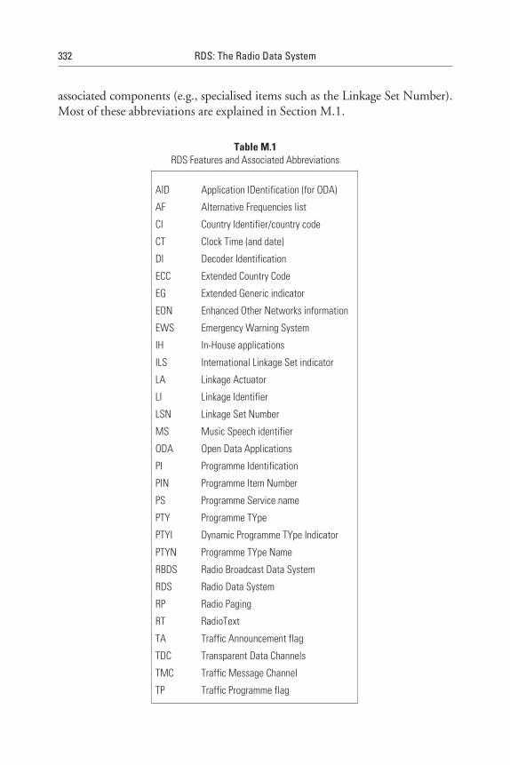
associated components (e.g., specialised items such as the Linkage Set Number).Most of these abbreviations are explained in Section M.1.
Table M.1RDS Features and Associated Abbreviations
AID Application IDentification (for ODA)
AF Alternative Frequencies list
CI Country Identifier/country code
CT Clock Time (and date)
DI Decoder Identification
ECC Extended Country Code
EG Extended Generic indicator
EON Enhanced Other Networks information
EWS Emergency Warning System
IH In-House applications
ILS International Linkage Set indicator
LA Linkage Actuator
LI Linkage Identifier
LSN Linkage Set Number
MS Music Speech identifier
ODA Open Data Applications
PI Programme Identification
PIN Programme Item Number
PS Programme Service name
PTY Programme TYpe
PTYI Dynamic Programme TYpe Indicator
PTYN Programme TYpe Name
RBDS Radio Broadcast Data System
RDS Radio Data System
RP Radio Paging
RT RadioText
TA Traffic Announcement flag
TDC Transparent Data Channels
TMC Traffic Message Channel
TP Traffic Programme flag
332 RDS: The Radio Data System
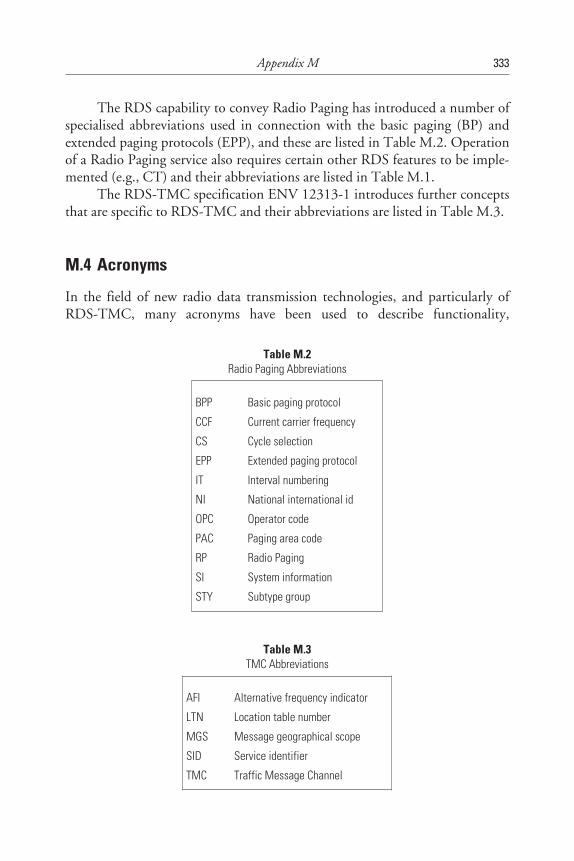
The RDS capability to convey Radio Paging has introduced a number ofspecialised abbreviations used in connection with the basic paging (BP) andextended paging protocols (EPP), and these are listed in Table M.2. Operationof a Radio Paging service also requires certain other RDS features to be imple-mented (e.g., CT) and their abbreviations are listed in Table M.1.
The RDS-TMC specification ENV 12313-1 introduces further conceptsthat are specific to RDS-TMC and their abbreviations are listed in Table M.3.
M.4 Acronyms
In the field of new radio data transmission technologies, and particularly ofRDS-TMC, many acronyms have been used to describe functionality,
Appendix M 333
Table M.3TMC Abbreviations
AFI Alternative frequency indicator
LTN Location table number
MGS Message geographical scope
SID Service identifier
TMC Traffic Message Channel
Table M.2Radio Paging Abbreviations
BPP Basic paging protocol
CCF Current carrier frequency
CS Cycle selection
EPP Extended paging protocol
IT Interval numbering
NI National international id
OPC Operator code
PAC Paging area code
RP Radio Paging
SI System information
STY Subtype group
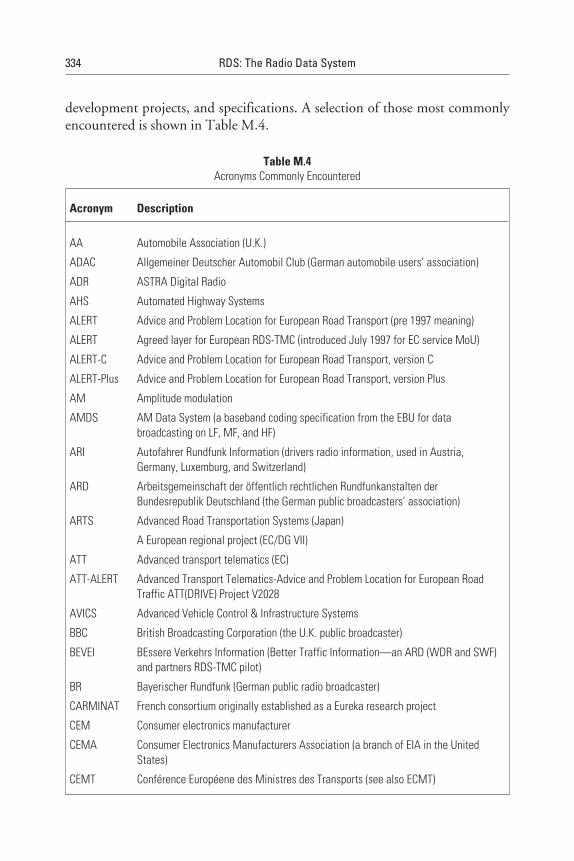
development projects, and specifications. A selection of those most commonlyencountered is shown in Table M.4.
334 RDS: The Radio Data System
Table M.4Acronyms Commonly Encountered
Acronym Description
AA Automobile Association (U.K.)
ADAC Allgemeiner Deutscher Automobil Club (German automobile users’ association)
ADR ASTRA Digital Radio
AHS Automated Highway Systems
ALERT Advice and Problem Location for European Road Transport (pre 1997 meaning)
ALERT Agreed layer for European RDS-TMC (introduced July 1997 for EC service MoU)
ALERT-C Advice and Problem Location for European Road Transport, version C
ALERT-Plus Advice and Problem Location for European Road Transport, version Plus
AM Amplitude modulation
AMDS AM Data System (a baseband coding specification from the EBU for databroadcasting on LF, MF, and HF)
ARI Autofahrer Rundfunk Information (drivers radio information, used in Austria,Germany, Luxemburg, and Switzerland)
ARD Arbeitsgemeinschaft der öffentlich rechtlichen Rundfunkanstalten derBundesrepublik Deutschland (the German public broadcasters’ association)
ARTS Advanced Road Transportation Systems (Japan)
A European regional project (EC/DG VII)
ATT Advanced transport telematics (EC)
ATT-ALERT Advanced Transport Telematics-Advice and Problem Location for European RoadTraffic ATT(DRIVE) Project V2028
AVICS Advanced Vehicle Control & Infrastructure Systems
BBC British Broadcasting Corporation (the U.K. public broadcaster)
BEVEI BEssere Verkehrs Information (Better Traffic Information—an ARD (WDR and SWF)and partners RDS-TMC pilot)
BR Bayerischer Rundfunk (German public radio broadcaster)
CARMINAT French consortium originally established as a Eureka research project
CEM Consumer electronics manufacturer
CEMA Consumer Electronics Manufacturers Association (a branch of EIA in the UnitedStates)
CEMT Conférence Européene des Ministres des Transports (see also ECMT)
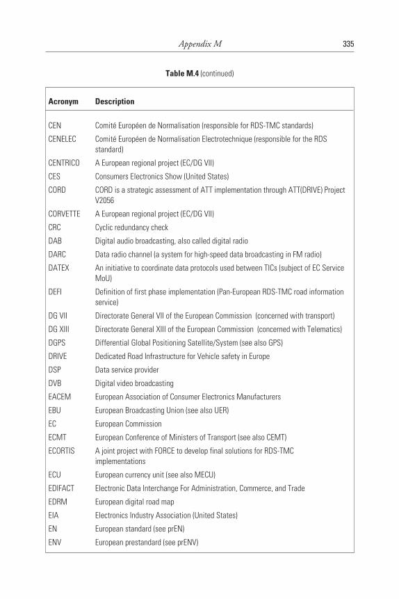
Appendix M 335
Table M.4 (continued)
Acronym Description
CEN Comité Européen de Normalisation (responsible for RDS-TMC standards)
CENELEC Comité Européen de Normalisation Electrotechnique (responsible for the RDSstandard)
CENTRICO A European regional project (EC/DG VII)
CES Consumers Electronics Show (United States)
CORD CORD is a strategic assessment of ATT implementation through ATT(DRIVE) ProjectV2056
CORVETTE A European regional project (EC/DG VII)
CRC Cyclic redundancy check
DAB Digital audio broadcasting, also called digital radio
DARC Data radio channel (a system for high-speed data broadcasting in FM radio)
DATEX An initiative to coordinate data protocols used between TICs (subject of EC ServiceMoU)
DEFI Definition of first phase implementation (Pan-European RDS-TMC road informationservice)
DG VII Directorate General VII of the European Commission (concerned with transport)
DG XIII Directorate General XIII of the European Commission (concerned with Telematics)
DGPS Differential Global Positioning Satellite/System (see also GPS)
DRIVE Dedicated Road Infrastructure for Vehicle safety in Europe
DSP Data service provider
DVB Digital video broadcasting
EACEM European Association of Consumer Electronics Manufacturers
EBU European Broadcasting Union (see also UER)
EC European Commission
ECMT European Conference of Ministers of Transport (see also CEMT)
ECORTIS A joint project with FORCE to develop final solutions for RDS-TMCimplementations
ECU European currency unit (see also MECU)
EDIFACT Electronic Data Interchange For Administration, Commerce, and Trade
EDRM European digital road map
EIA Electronics Industry Association (United States)
EN European standard (see prEN)
ENV European prestandard (see prENV)
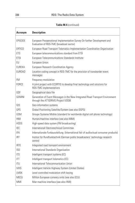
336 RDS: The Radio Data System
Table M.4 (continued)
Acronym Description
EPISODE European Preoperational Implementation Survey On further Development andEvaluation of RDS-TMC (broadcast sector)
ERTICO European Road Transport Telematics Implementation Coordination Organisation
ETS European telecommunications standard from ETSI
ETSI European Telecommunications Standards Institute
EU European Union
EUREKA European Research Coordination Agency
EUROAD Location coding concept in RDS-TMC for the provision of transborder eventmessages
FM Frequency modulation
FORCE A joint project with ECORTIS to develop final technology and solutions forRDS-TMC implementations
GDF Geographical data file
GEMINI Generation of Event Messages in the New Integrated Road Transport Environmentthrough the ATT(DRIVE) Project V2038
GIS Geo-information systems
GPS Global Positioning Satellite/System (see also DGPS)
GSM Groupe Systeme Mobile (standard for worldwide digital cell phone technology)
HMI Human/machine interface (see also MMI)
HSDS High-speed data system (FM broadcasting)
IEC International Electrotechnical Committee
IFA Internationale Funkausstellung (International fair of audiovisual consumer products)
IRT Institut für Rundfunktechnik (German public broadcasters’ technology researchcentre)
IRTE Integrated road transport environment
ISO International Standards Organisation
ITS Intelligent transport systems (EC)
ITT Intelligent transport telematics (EC)
ITU International Telecommunication Union
IVHS Intelligent Vehicle Highway System (United States)
LMSK Level controlled modulation shift keying
MECU Million European currency units (see also ECU)
MMI Man machine interface (see also HMI)
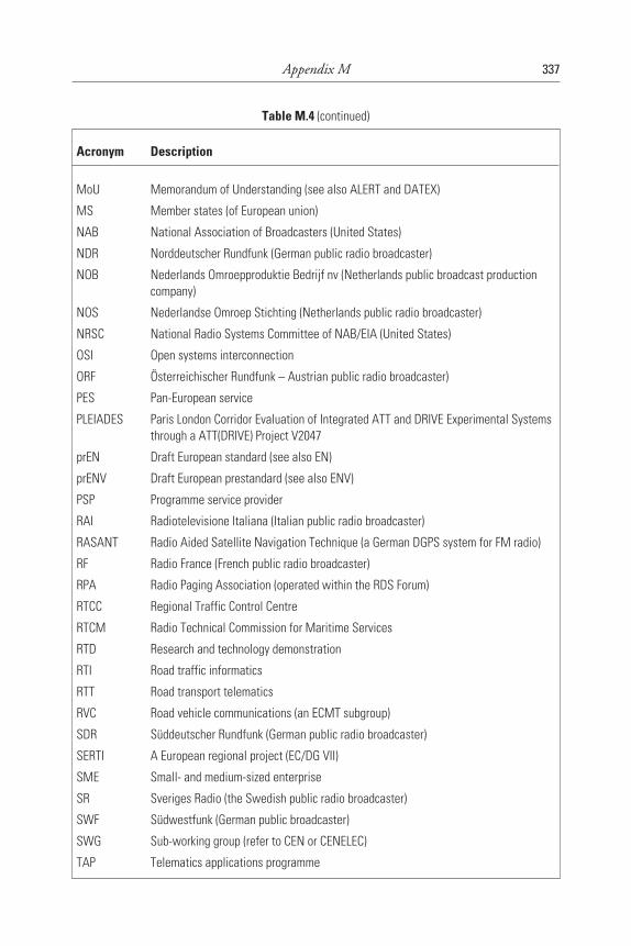
Appendix M 337
Table M.4 (continued)
Acronym Description
MoU Memorandum of Understanding (see also ALERT and DATEX)
MS Member states (of European union)
NAB National Association of Broadcasters (United States)
NDR Norddeutscher Rundfunk (German public radio broadcaster)
NOB Nederlands Omroepproduktie Bedrijf nv (Netherlands public broadcast productioncompany)
NOS Nederlandse Omroep Stichting (Netherlands public radio broadcaster)
NRSC National Radio Systems Committee of NAB/EIA (United States)
OSI Open systems interconnection
ORF Österreichischer Rundfunk – Austrian public radio broadcaster)
PES Pan-European service
PLEIADES Paris London Corridor Evaluation of Integrated ATT and DRIVE Experimental Systemsthrough a ATT(DRIVE) Project V2047
prEN Draft European standard (see also EN)
prENV Draft European prestandard (see also ENV)
PSP Programme service provider
RAI Radiotelevisione Italiana (Italian public radio broadcaster)
RASANT Radio Aided Satellite Navigation Technique (a German DGPS system for FM radio)
RF Radio France (French public radio broadcaster)
RPA Radio Paging Association (operated within the RDS Forum)
RTCC Regional Traffic Control Centre
RTCM Radio Technical Commission for Maritime Services
RTD Research and technology demonstration
RTI Road traffic informatics
RTT Road transport telematics
RVC Road vehicle communications (an ECMT subgroup)
SDR Süddeutscher Rundfunk (German public radio broadcaster)
SERTI A European regional project (EC/DG VII)
SME Small- and medium-sized enterprise
SR Sveriges Radio (the Swedish public radio broadcaster)
SWF Südwestfunk (German public broadcaster)
SWG
TAP
Sub-working group (refer to CEN or CENELEC)
Telematics applications programme
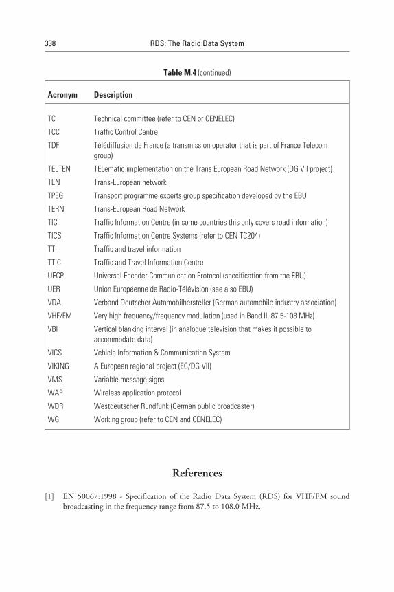
References
[1] EN 50067:1998 - Specification of the Radio Data System (RDS) for VHF/FM soundbroadcasting in the frequency range from 87.5 to 108.0 MHz.
338 RDS: The Radio Data System
Table M.4 (continued)
Acronym Description
TC Technical committee (refer to CEN or CENELEC)
TCC Traffic Control Centre
TDF Télédiffusion de France (a transmission operator that is part of France Telecomgroup)
TELTEN TELematic implementation on the Trans European Road Network (DG VII project)
TEN Trans-European network
TPEG Transport programme experts group specification developed by the EBU
TERN Trans-European Road Network
TIC Traffic Information Centre (in some countries this only covers road information)
TICS Traffic Information Centre Systems (refer to CEN TC204)
TTI Traffic and travel information
TTIC Traffic and Travel Information Centre
UECP Universal Encoder Communication Protocol (specification from the EBU)
UER Union Européenne de Radio-Télévision (see also EBU)
VDA Verband Deutscher Automobilhersteller (German automobile industry association)
VHF/FM Very high frequency/frequency modulation (used in Band II, 87.5-108 MHz)
VBI Vertical blanking interval (in analogue television that makes it possible toaccommodate data)
VICS Vehicle Information & Communication System
VIKING A European regional project (EC/DG VII)
VMS Variable message signs
WAP Wireless application protocol
WDR Westdeutscher Rundfunk (German public broadcaster)
WG Working group (refer to CEN and CENELEC)
About the Authors
Dietmar Kopitz has coordinated all RDS development work within theEuropean Broadcasting Union since the 1970s, participating in specificationwriting, elaboration of the implementation guidelines, and the Europeanand U.S. standardisation processes. He is a founder and co-chairman of theRDS Forum. In the field of RDS-TMC, he led the European Commissionfunded EPISODE project.
Bev Marks contributed to the initial BBC RDS studio and transmitter net-works implementations. For several years he has been a freelance broadcastengineer working on a number of special projects for the EBU related to radiodata broadcasting. He is involved in the RDS Forum on RDS guidelinesdevelopment and in the EPISODE project concerning standardisation ofRDS-TMC.
339
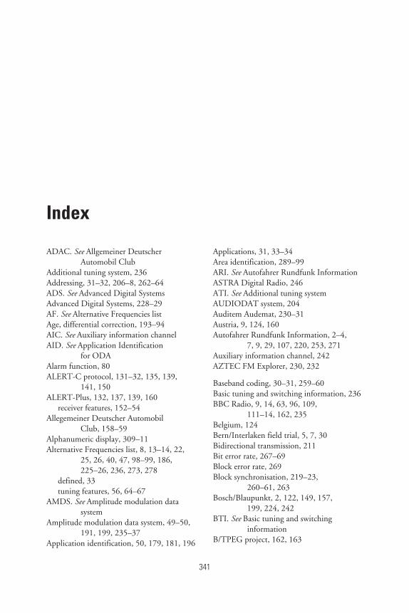
Index
ADAC. See Allgemeiner DeutscherAutomobil Club
Additional tuning system, 236Addressing, 31–32, 206–8, 262–64ADS. See Advanced Digital SystemsAdvanced Digital Systems, 228–29AF. See Alternative Frequencies listAge, differential correction, 193–94AIC. See Auxiliary information channelAID. See Application Identification
for ODAAlarm function, 80ALERT-C protocol, 131–32, 135, 139,
141, 150ALERT-Plus, 132, 137, 139, 160
receiver features, 152–54Allegemeiner Deutscher Automobil
Club, 158–59Alphanumeric display, 309–11Alternative Frequencies list, 8, 13–14, 22,
25, 26, 40, 47, 98–99, 186,225–26, 236, 273, 278
defined, 33tuning features, 56, 64–67
AMDS. See Amplitude modulation datasystem
Amplitude modulation data system, 49–50,191, 199, 235–37
Application identification, 50, 179, 181, 196
Applications, 31, 33–34Area identification, 289–99ARI. See Autofahrer Rundfunk InformationASTRA Digital Radio, 246ATI. See Additional tuning systemAUDIODAT system, 204Auditem Audemat, 230–31Austria, 9, 124, 160Autofahrer Rundfunk Information, 2–4,
7, 9, 29, 107, 220, 253, 271Auxiliary information channel, 242AZTEC FM Explorer, 230, 232
Baseband coding, 30–31, 259–60Basic tuning and switching information, 236BBC Radio, 9, 14, 63, 96, 109,
111–14, 162, 235Belgium, 124Bern/Interlaken field trial, 5, 7, 30Bidirectional transmission, 211Bit error rate, 267–69Block error rate, 269Block synchronisation, 219–23,
260–61, 263Bosch/Blaupunkt, 2, 122, 149, 157,
199, 224, 242BTI. See Basic tuning and switching
informationB/TPEG project, 162, 163
341
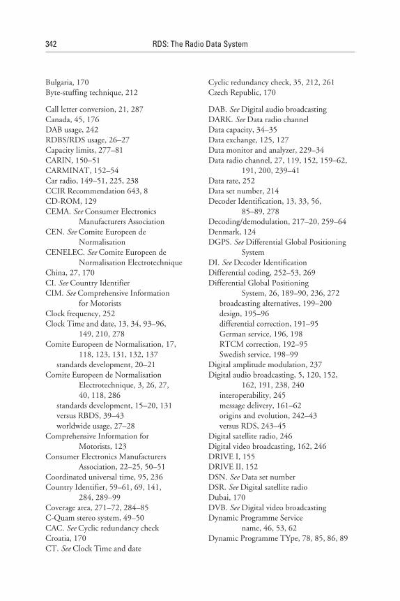
Bulgaria, 170Byte-stuffing technique, 212
Call letter conversion, 21, 287Canada, 45, 176DAB usage, 242RDBS/RDS usage, 26–27Capacity limits, 277–81CARIN, 150–51CARMINAT, 152–54Car radio, 149–51, 225, 238CCIR Recommendation 643, 8CD-ROM, 129CEMA. See Consumer Electronics
Manufacturers AssociationCEN. See Comite Europeen de
NormalisationCENELEC. See Comite Europeen de
Normalisation ElectrotechniqueChina, 27, 170CI. See Country IdentifierCIM. See Comprehensive Information
for MotoristsClock frequency, 252Clock Time and date, 13, 34, 93–96,
149, 210, 278Comite Europeen de Normalisation, 17,
118, 123, 131, 132, 137standards development, 20–21
Comite Europeen de NormalisationElectrotechnique, 3, 26, 27,40, 118, 286
standards development, 15–20, 131versus RBDS, 39–43worldwide usage, 27–28
Comprehensive Information forMotorists, 123
Consumer Electronics ManufacturersAssociation, 22–25, 50–51
Coordinated universal time, 95, 236Country Identifier, 59–61, 69, 141,
284, 289–99Coverage area, 271–72, 284–85C-Quam stereo system, 49–50CAC. See Cyclic redundancy checkCroatia, 170CT. See Clock Time and date
Cyclic redundancy check, 35, 212, 261Czech Republic, 170
DAB. See Digital audio broadcastingDARK. See Data radio channelData capacity, 34–35Data exchange, 125, 127Data monitor and analyzer, 229–34Data radio channel, 27, 119, 152, 159–62,
191, 200, 239–41Data rate, 252Data set number, 214Decoder Identification, 13, 33, 56,
85–89, 278Decoding/demodulation, 217–20, 259–64Denmark, 124DGPS. See Differential Global Positioning
SystemDI. See Decoder IdentificationDifferential coding, 252–53, 269Differential Global Positioning
System, 26, 189–90, 236, 272broadcasting alternatives, 199–200design, 195–96differential correction, 191–95German service, 196, 198RTCM correction, 192–95Swedish service, 198–99
Digital amplitude modulation, 237Digital audio broadcasting, 5, 120, 152,
162, 191, 238, 240interoperability, 245message delivery, 161–62origins and evolution, 242–43versus RDS, 243–45
Digital satellite radio, 246Digital video broadcasting, 162, 246DRIVE I, 155DRIVE II, 152DSN. See Data set numberDSR. See Digital satellite radioDubai, 170DVB. See Digital video broadcastingDynamic Programme Service
name, 46, 53, 62Dynamic Programme TYpe, 78, 85, 86, 89
342 RDS: The Radio Data System
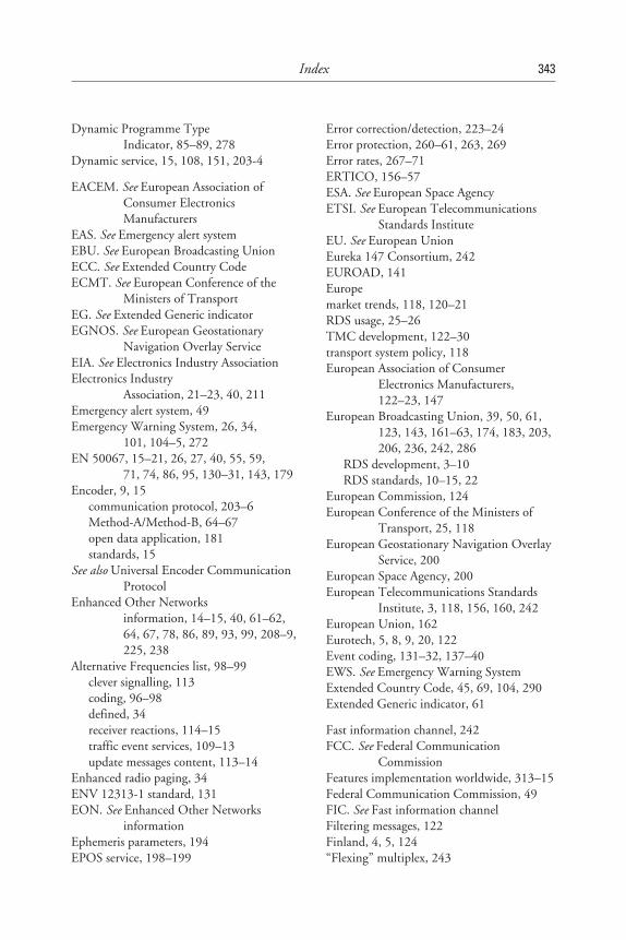
Dynamic Programme TypeIndicator, 85–89, 278
Dynamic service, 15, 108, 151, 203-4
EACEM. See European Association ofConsumer ElectronicsManufacturers
EAS. See Emergency alert systemEBU. See European Broadcasting UnionECC. See Extended Country CodeECMT. See European Conference of the
Ministers of TransportEG. See Extended Generic indicatorEGNOS. See European Geostationary
Navigation Overlay ServiceEIA. See Electronics Industry AssociationElectronics Industry
Association, 21–23, 40, 211Emergency alert system, 49Emergency Warning System, 26, 34,
101, 104–5, 272EN 50067, 15–21, 26, 27, 40, 55, 59,
71, 74, 86, 95, 130–31, 143, 179Encoder, 9, 15
communication protocol, 203–6Method-A/Method-B, 64–67open data application, 181standards, 15
See also Universal Encoder CommunicationProtocol
Enhanced Other Networksinformation, 14–15, 40, 61–62,64, 67, 78, 86, 89, 93, 99, 208–9,225, 238
Alternative Frequencies list, 98–99clever signalling, 113coding, 96–98defined, 34receiver reactions, 114–15traffic event services, 109–13update messages content, 113–14
Enhanced radio paging, 34ENV 12313-1 standard, 131EON. See Enhanced Other Networks
informationEphemeris parameters, 194EPOS service, 198–199
Error correction/detection, 223–24Error protection, 260–61, 263, 269Error rates, 267–71ERTICO, 156–57ESA. See European Space AgencyETSI. See European Telecommunications
Standards InstituteEU. See European UnionEureka 147 Consortium, 242EUROAD, 141Europemarket trends, 118, 120–21RDS usage, 25–26TMC development, 122–30transport system policy, 118European Association of Consumer
Electronics Manufacturers,122–23, 147
European Broadcasting Union, 39, 50, 61,123, 143, 161–63, 174, 183, 203,206, 236, 242, 286
RDS development, 3–10RDS standards, 10–15, 22
European Commission, 124European Conference of the Ministers of
Transport, 25, 118European Geostationary Navigation Overlay
Service, 200European Space Agency, 200European Telecommunications Standards
Institute, 3, 118, 156, 160, 242European Union, 162Eurotech, 5, 8, 9, 20, 122Event coding, 131–32, 137–40EWS. See Emergency Warning SystemExtended Country Code, 45, 69, 104, 290Extended Generic indicator, 61
Fast information channel, 242FCC. See Federal Communication
CommissionFeatures implementation worldwide, 313–15Federal Communication Commission, 49FIC. See Fast information channelFiltering messages, 122Finland, 4, 5, 124“Flexing” multiplex, 243
Index 343
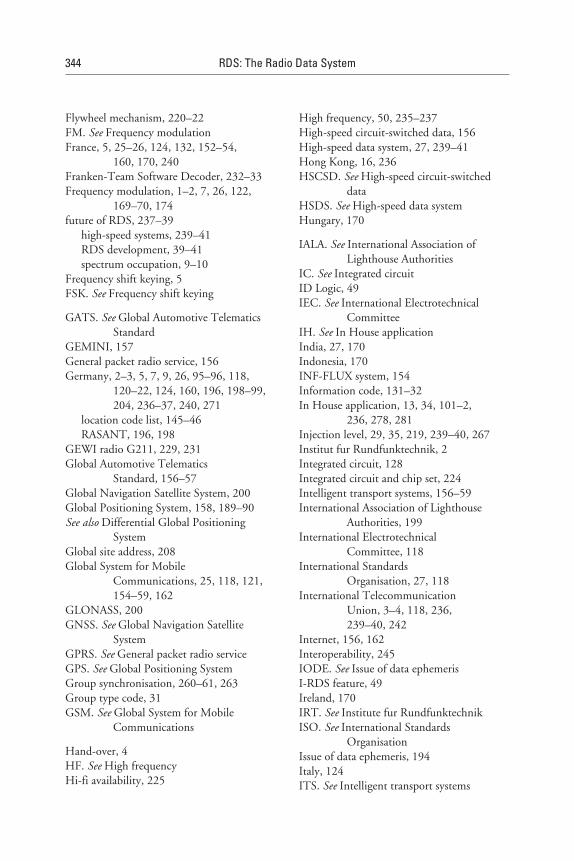
Flywheel mechanism, 220–22FM. See Frequency modulationFrance, 5, 25–26, 124, 132, 152–54,
160, 170, 240Franken-Team Software Decoder, 232–33Frequency modulation, 1–2, 7, 26, 122,
169–70, 174future of RDS, 237–39
high-speed systems, 239–41RDS development, 39–41spectrum occupation, 9–10
Frequency shift keying, 5FSK. See Frequency shift keying
GATS. See Global Automotive TelematicsStandard
GEMINI, 157General packet radio service, 156Germany, 2–3, 5, 7, 9, 26, 95–96, 118,
120–22, 124, 160, 196, 198–99,204, 236–37, 240, 271
location code list, 145–46RASANT, 196, 198
GEWI radio G211, 229, 231Global Automotive Telematics
Standard, 156–57Global Navigation Satellite System, 200Global Positioning System, 158, 189–90See also Differential Global Positioning
SystemGlobal site address, 208Global System for Mobile
Communications, 25, 118, 121,154–59, 162
GLONASS, 200GNSS. See Global Navigation Satellite
SystemGPRS. See General packet radio serviceGPS. See Global Positioning SystemGroup synchronisation, 260–61, 263Group type code, 31GSM. See Global System for Mobile
Communications
Hand-over, 4HF. See High frequencyHi-fi availability, 225
High frequency, 50, 235–237High-speed circuit-switched data, 156High-speed data system, 27, 239–41Hong Kong, 16, 236HSCSD. See High-speed circuit-switched
dataHSDS. See High-speed data systemHungary, 170
IALA. See International Association ofLighthouse Authorities
IC. See Integrated circuitID Logic, 49IEC. See International Electrotechnical
CommitteeIH. See In House applicationIndia, 27, 170Indonesia, 170INF-FLUX system, 154Information code, 131–32In House application, 13, 34, 101–2,
236, 278, 281Injection level, 29, 35, 219, 239–40, 267Institut fur Rundfunktechnik, 2Integrated circuit, 128Integrated circuit and chip set, 224Intelligent transport systems, 156–59International Association of Lighthouse
Authorities, 199International Electrotechnical
Committee, 118International Standards
Organisation, 27, 118International Telecommunication
Union, 3–4, 118, 236,239–40, 242
Internet, 156, 162Interoperability, 245IODE. See Issue of data ephemerisI-RDS feature, 49Ireland, 170IRT. See Institute fur RundfunktechnikISO. See International Standards
OrganisationIssue of data ephemeris, 194Italy, 124ITS. See Intelligent transport systems
344 RDS: The Radio Data System
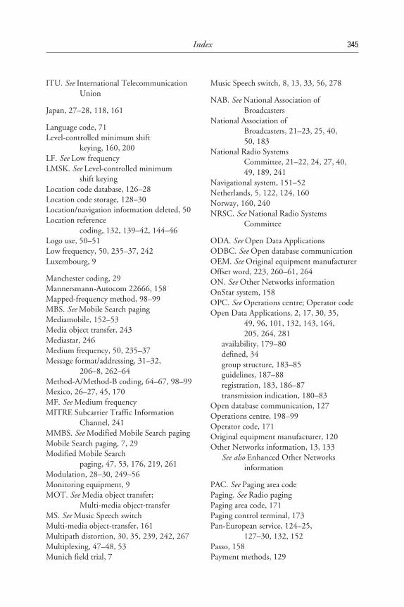
ITU. See International TelecommunicationUnion
Japan, 27–28, 118, 161
Language code, 71Level-controlled minimum shift
keying, 160, 200LF. See Low frequencyLMSK. See Level-controlled minimum
shift keyingLocation code database, 126–28Location code storage, 128–30Location/navigation information deleted, 50Location reference
coding, 132, 139–42, 144–46Logo use, 50–51Low frequency, 50, 235–37, 242Luxembourg, 9
Manchester coding, 29Mannersmann-Autocom 22666, 158Mapped-frequency method, 98–99MBS. See Mobile Search pagingMediamobile, 152–53Media object transfer, 243Mediastar, 246Medium frequency, 50, 235–37Message format/addressing, 31–32,
206–8, 262–64Method-A/Method-B coding, 64–67, 98–99Mexico, 26–27, 45, 170MF. See Medium frequencyMITRE Subcarrier Traffic Information
Channel, 241MMBS. See Modified Mobile Search pagingMobile Search paging, 7, 29Modified Mobile Search
paging, 47, 53, 176, 219, 261Modulation, 28–30, 249–56Monitoring equipment, 9MOT. See Media object transfer;
Multi-media object-transferMS. See Music Speech switchMulti-media object-transfer, 161Multipath distortion, 30, 35, 239, 242, 267Multiplexing, 47–48, 53Munich field trial, 7
Music Speech switch, 8, 13, 33, 56, 278
NAB. See National Association ofBroadcasters
National Association ofBroadcasters, 21–23, 25, 40,50, 183
National Radio SystemsCommittee, 21–22, 24, 27, 40,49, 189, 241
Navigational system, 151–52Netherlands, 5, 122, 124, 160Norway, 160, 240NRSC. See National Radio Systems
Committee
ODA. See Open Data ApplicationsODBC. See Open database communicationOEM. See Original equipment manufacturerOffset word, 223, 260–61, 264ON. See Other Networks informationOnStar system, 158OPC. See Operations centre; Operator codeOpen Data Applications, 2, 17, 30, 35,
49, 96, 101, 132, 143, 164,205, 264, 281
availability, 179–80defined, 34group structure, 183–85guidelines, 187–88registration, 183, 186–87transmission indication, 180–83
Open database communication, 127Operations centre, 198–99Operator code, 171Original equipment manufacturer, 120Other Networks information, 13, 133
See also Enhanced Other Networksinformation
PAC. See Paging area codePaging. See Radio pagingPaging area code, 171Paging control terminal, 173Pan-European service, 124–25,
127–30, 132, 152Passo, 158Payment methods, 129
Index 345
PCT. See Paging control terminalPerformance, system, 35–36PES. See Pan-European servicePhase-locked loop, 29, 217–19Phase shift keying, 252Philips integrated circuit, 224Philips RC 579, 150–51Philips Smart radio, 226–28PI. See Programme IdentificationPIN. See Programme Item NumberPLL. See Phase-locked loopPlug-in card, 226–29Pool store memory, 99–100Portable radio, 225–26Portugal, 124PRC. See Pseudo-range correctionPRD software, 233–34prENV standard, 131–32, 137, 139Private service, 186Programme Identification, 4–7, 13,
21–22, 25, 31, 35, 40, 171,173, 225–26, 264, 270, 278
broadcasting, 59–61coding rules, 286–287coding structure, 45–46, 53,
283–85, 290defined, 33reception, 61–62tuning, 56–62
Programme ItemNumber, 13, 34, 89–91, 99,274, 278
Programme reference number, 285Programme Service
name, 13, 22, 25, 35, 40, 99,101, 208–9, 225, 226, 273, 278
characteristics, 46–47defined, 33dynamic, 46, 53, 62fast acquisition, 47, 53tuning features, 62–63
Programme TYpe, 8, 13–14, 21, 25, 31,40, 53, 56, 80, 99, 226, 238, 264,270, 278
defined, 33display terms, 301–6dynamic, 78, 85–86, 89
features/usage, 43–45group 15B, 74–75programme coding, 73–78search mode, 77, 79, 81select mode, 77, 79standby mode, 74, 77–79, 81, 85, 86, 91store mode, 77, 80–81, 85
Programme TYpe name, 44, 80–82PROMETHEUS, 148PROMISE, 156PS. See Programme Service namePSA Peugot/Citroen, 154Pseudo-range correction, 193PSK. See Phase shift keyingPSTN. See Public switched telephone
networkPTY. See Programme TYpePTYI. See Dynamic Programme Type
IndicatorPTYN. See Programme TYpe namePublic service, 186Public switched telephone network, 173
Radio Aided Satellite NavigationTechnique, 196, 198
Radio Broadcast Data System, 1, 21, 196versus RDS, 21–22, 51–53North American usage, 26–27RDS component within, 39–43Radio Data System, 1, 237–39Radio Paging, 8, 14, 25, 26, 95, 272,
278, 281defined, 34features, 169–73future, 176–77infrastructure, 173–74message types, 171receiver design, 175–16reliability, 35–36
Radio Paging Association, 176Radio Rock-It RDS, 228–29Radio Technical Commission for Maritime
Services, 192–95RadioText, 13, 25, 55, 62, 153, 226,
236, 238coding, 81, 83–85computer display, 86
346 RDS: The Radio Data System
defined, 34Range rate correction, 193RASANT. See Radio Aided Satellite
Navigation TechniqueRBDS. See Radio Broadcast Data SystemRDS. See Radio data systemRDS Advisory Group, 24RDS Forum, 15, 22–23, 26, 40, 46, 61,
62, 74, 143, 176, 189, 196,206, 245, 301, 318
RDS Software Decoder, 232–33Receivers
ALERT-Plus, 152–54car radio, 149–51, 225design, 13–14, 52–53, 84–85,
93, 225–26Enhanced Other Networks, 114–15European industry, 147–48market trends, 120navigational systems, 151–52Radio Paging, 175–76requirements, 148–49
Reference station location, 194–95Regional Programme Identification, 60–61Reliability, system, 35–36, 174, 267–72Renault, 152, 154Repetition rate, 273–75Road traffic informatics, 151–52Roller mechanism, 222Romania, 69RP. See Radio PagingRRC. See Range rate correctionRT. See RadioTextRTCM. See Radio Technical Commission
for Maritime ServicesRTI. See Road traffic informaticsRussia, 170Russian Federation, 200
Safety, 121Sagem, 152Satellite-based positioning, 189–90Satellite digital radio, 246Satellite identification, 194SATID. See Satellite identificationScandinavia, 4, 5, 7Scheduling information, 236
Schumperlin software, 233–34Search mode, 77, 79, 81Seiko Telecommunication System, 241Select mode, 77, 79Service Identification, 129Service information, digital audio
broadcasting, 243–45Service provider, 126SFN. See Single frequency networkSGS-Thomson integrated circuit, 224Short message service, 155–56SI. See Scheduling information; Service
informationSId. See Service IdentificationSingle frequency network, 245Single-sided broadcasting, 236Site address, 207–8Slovak Republic, 170Slovenia, 170Slow labelling code, 69–71Smart card, 128–30, 148Smart Radio, 226–28SMS. See Short message serviceSOCRATES, 155South Africa, 16, 170South Korea, 27SP. See Service providerSpain, 69, 124, 170SPB 482 and 485, 16Spectrum shaping, 253–56SSB. See Single-sided broadcastingStandards
CEN, 20–21CENELEC, 15–20data exchange, 127EBU, 10–15Radio Paging, 170–71receiver, 148subcarrier, 241Traffic Message Channel, 130–32UECP, 211–15United States, 21–22
Standby mode, 74, 77–79, 81, 85–86,91, 99
Static service, 203STIC. See Subcarrier Traffic Information
Channel
Index 347

Store mode, 77, 80–81, 85Subcarrier, 28–29, 52, 160, 239–41
modulation, 249–56Subcarrier Traffic Information Channel, 241Sweden, 4, 5, 7, 26, 69, 96, 124, 160,
161, 170, 198–199, 240SWIFT. See System for Wireless
Infotainment Forwarding andTeledistribution
Switzerland, 5, 7, 9, 199, 240Synchronisation, 219–23, 260–61, 263System for Wireless Infotainment
Forwarding and Teledistribution,159–61, 240
TA. See Traffic Announcement flagTanzania, 170TDC. See Transparent Data ChannelsTDF. See Telediffusion de FranceTegaron, 158Telediffusion de France, 152, 160Telematics, 118–21, 164Telocator Network Paging Protocol, 174TELTEN project, 120Teracom, 160, 199–99TERN. See Trans-European Road NetworkTIC. See Traffic information centreTMC. See Traffic Message ChannelTNPP. See Telocator Network Paging
ProtocolTP. See Traffic Programme flagTPEG. See Transport Programme
Experts GroupTraffic and travel information, 118, 121–22Traffic Announcement
flag, 8, 13, 15, 22, 25, 33, 40, 56,101, 107–9, 114–15, 225, 278
Traffic information centre, 126, 127Traffic Message
Channel, 2, 9, 20–21, 27, 40, 95,117, 236
challenges, 125–30coding, 137–47coverage area, 272data formats, 132–37development, 122–24location databases, 126–28
market trends, 118–21message construction, 143objectives/policy, 118, 122, 124receiver design, 147–54safety issues, 121standards, 130–32
TPEG enhancement, 243transmission capacity, 278, 281Traffic Message Channel chip card, 128Traffic Programme
flag, 8, 13, 22, 25, 33, 56,67–69, 40, 101, 107–9, 114,225, 264, 270, 278
Trans-European RoadNetwork, 124–25, 141
Transparent DataChannels, 13, 34, 101, 103,236, 278, 281
Transport Programme ExpertsGroup, 162–63, 243
Travel and traffic information, 111TTI. See Travel and traffic informationTuning
Alternative Frequencies list, 64–67basic features, 55–56frequency synthesized, 217–20group types, 55–56Programme Identification, 56–62Programme Service name, 62–63slow labelling codes, 69–71
Traffic Programme flag, 67–69, 114
UDRE. See User differential range errorUECP. See Universal Encoder
Communication ProtocolUkraine, 170UMTS. See Universal Mobile
Telecommunication SystemUnidirectional transmission, 211United Kingdom, 5, 14, 26, 63, 95–96,
109, 111–14, 121, 124, 162United States
Radio Paging, 170, 176RDBS/RDS usage, 26–27standards promotion, 23–25standards development, 21–22transport system policy, 118
348 RDS: The Radio Data System
Universal Encoder CommunicationProtocol, 15, 23, 143, 147,174, 246
addressing, 206–8conceptual method, 208–11hardware model, 210–11message commands, 319–24need for, 203–6protocol, 211–15software model, 208–10transmission modes, 211
Universal Mobile TelecommunicationSystem, 156
Update message, 113–14User differential range error, 194UTC. See Coordinated universal time
Vehicle Information and CommunicationSystem, 119, 161
Very high frequency, 1, 122, 169, 170,174, 176, 217, 242
VHF. See Very high frequencyVICS. See Vehicle Information and
Communication SystemVisionaute terminal, 153–54Volvo, 13–14, 151–52
Waiting time, 35WAP. See Wireless Application ProtocolWDR. See Westdeutscher RundfunkWestdeutscher Rundfunk, 198Wireless Application Protocol, 157Worldwide usage, 25–28, 313–15WorldSpace, 246
Index 349