Raytek - Instrumart · 69 APPENDIX E CUTOUT TEMPLATE AND COSMETIC FRAME 71 APPENDIX F TRACEABILITY...
84
Thermalert ® GP Series Operator’s Manual Raytek ® Infrared Temperature Measurement 58823-9 Rev C 11/2002
Transcript of Raytek - Instrumart · 69 APPENDIX E CUTOUT TEMPLATE AND COSMETIC FRAME 71 APPENDIX F TRACEABILITY...

Thermalert®
GP Series
Operator’s Manual
Raytek®
Infrared Temperature Measurement
58823-9Rev C 11/2002

Worldwide HeadquartersRaytek Corporation
Box 1820, Santa Cruz, CA95061-1820Phone: (831) 458-1110
(800) 227-8074FAX: (831) 458-1239
Raytek MexicoPhone: 55-22 30-4380FAX: 55-22 30-4438
Raytek do BrasilPhone: 55-15-233-6338FAX: 55-15-233-6826
Raytek China CompanyPhone: 86-10/6437-0284FAX: 86-10/6437-0285
Raytek Japan, Inc.Phone: 81-6-4390-5015FAX: 81-6-4390-5016
European HeadquartersRaytek GmbH
Berlin, GermanyPhone: 49 030/47 80 08-0FAX: 49 030/47 10 25-1
Raytek UK Ltd.Phone: 441-908/630800FAX: 441-908/630900
Raytek FrancePhone: +33 1 64 53 15 40FAX: +33 1 64 53 15 44
Internet Address: http://www.raytek.com
Raytek and Thermalert are registered trademarks of Raytek Corp. All otherbrands or products are trademarks of their respective owners.
© 2001 Raytek Corporation

WARRANTY
Raytek warrants this instrument to be free from defects in material andworkmanship under normal use and service for the period of two yearsfrom date of purchase. This warranty extends only to the original pur-chaser. This warranty shall not apply to fuses, batteries, or any productwhich has been subject to misuse, neglect, accident, or abnormal condi-tions of operation.
In the event of failure of a product covered by this warranty, Raytek willrepair the instrument when it is returned to an authorized Service Facilitywithin two years of the original purchase, provided the warrantor’sexamination discloses to its satisfaction that the product was defective.The warrantor may, at its option, replace the product in lieu of repair.With regard to any instrument returned within two years of the originalpurchase, said repairs or replacement will be made without charge. If thefailure has been caused by misuse, neglect, accident, or abnormal condi-tions of operation, repairs will be billed at nominal cost. In such cases, anestimate will be submitted before work is started, if requested.
THE FOREGOING WARRANTY IS IN LIEU OF ALL OTHER WAR-RANTIES, EXPRESSED OR IMPLIED, INCLUDING BUT NOT LIM-ITED TO ANY IMPLIED WARRANTY OF MERCHANTIBILITY, FIT-NESS, OR ADEQUACY FOR ANY PARTICULAR PURPOSE OR USE.RAYTEK SHALL NOT BE LIABLE FOR ANY SPECIAL, INCIDENTALOR CONSEQUENTIAL DAMAGES, WHETHER IN CONTRACT,TORT, OR OTHERWISE.


TABLE OF CONTENTS
QUICK REFERENCE
SEE APPENDIX A
SECTION PAGE
1.0 DESCRIPTION
1
2.0 THERMALERT GP MONITOR
2
2.1 SPECIFICATIONS
2
2.1.1 Operational
2
2.1.2 Electrical
3
2.1.3 Physical
3
2.2 MOUNTING INSTRUCTIONS
4
2.3 ELECTRICAL INSTALLATION
5
2.3.1 Terminal Block Layout
5
2.3.2 Connecting Input Devices
6
2.3.3 Power Connections
7
2.3.4 Output Connections
8
2.3.5 Relay Accessory
8
2.4 OPERATION
9
2.4.1 Display/Key Pad
10
2.4.2 Device Selection
11
2.4.3 Emissivity
14
2.4.4 Setpoints 1 and 2
15
2.4.5 4-20mA Analog Output
19
2.4.6 Degrees C and F
20
2.4.7 Peak Hold, Valley Hold, and Average
21
2.4.8 Ambient Temperature Compensation (T-ambient)
23
2.4.9 Display and Analog Output Offsets
24
2.4.10 Thermocouple Output
25
2.4.11 Lockout Mode
26
2.4.11 Factory Defaults
26
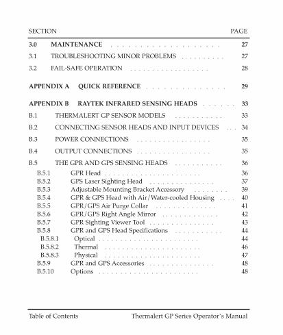
Thermalert GP Series Operator’s Manual Table of Contents
SECTION PAGE
3.0 MAINTENANCE
27
3.1 TROUBLESHOOTING MINOR PROBLEMS
27
3.2 FAIL-SAFE OPERATION
28
APPENDIX A QUICK REFERENCE
29
APPENDIX B RAYTEK INFRARED SENSING HEADS
33
B.1 THERMALERT GP SENSOR MODELS
33
B.2 CONNECTING SENSOR HEADS AND INPUT DEVICES
34
B.3 POWER CONNECTIONS
35
B.4 OUTPUT CONNECTIONS
35
B.5 THE GPR AND GPS SENSING HEADS
36
B.5.1 GPR Head
36
B.5.2 GPS Laser Sighting Head
37
B.5.3 Adjustable Mounting Bracket Accessory
39
B.5.4 GPR & GPS Head with Air/Water-cooled Housing
40
B.5.5 GPR/GPS Air Purge Collar
41
B.5.6 GPR/GPS Right Angle Mirror
42
B.5.7 GPR Sighting Viewer Tool
43
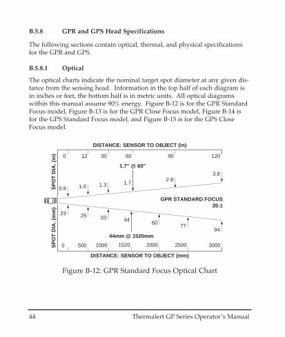
B.5.8 GPR and GPS Head Specifications
44
B.5.8.1 Optical
44
B.5.8.2 Thermal
46
B.5.8.3 Physical
47
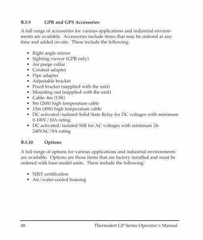
B.5.9 GPR and GPS Accessories
48
B.5.10 Options
48
Table of Contents Thermalert GP Series Operator’s Manual

SECTION PAGE
B.6 GP MINIATURE HEAD INFORMATION
49
B.6.1 GPM Head
49
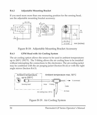
B.6.2 Adjustable Mounting Bracket
50
B.6.3 GPM Head with Air Cooling System
50
B.6.4 GPM Air Purge Jacket
52
B.6.5 GPM Right Angle Mirror
53
B.6.6 GPM Head Specifications
54
B.6.6.1 Optical
54
B.6.6.2 Thermal
55
B.6.6.3 Physical
55
B.6.6.4 Environmental
55
B.6.7 GP Miniature Head Accessories
56
B.6.8 Options
56
B.7 INSTALLATION OF SENSING HEADS
57
B.7.1 Preparation
57
B.7.1.1 Ambient Temperature
57
B.7.1.2 Distance and Spot Size
58
B.7.1.3 Atmospheric Quality
59
B.7.1.4 Electrical Interference
59
B.7.2 GPR/GPS Mechanical Installation
60
B.7.3 GPR/GPS Electrical Installation
60
B.7.4 GPM Mechanical Installation
61
B.7.5 GPM Electrical Installation
61
B.7.6 Aiming the Sensing Head
62
B.7.7 Cleaning the Sensing Head Lens
63
Thermalert GP Series Operator’s Manual Table of Contents

Table of Contents Thermalert GP Series Operator’s Manual
SECTION PAGE
APPENDIX C EMISSIVITY
65
C.1 HOW TO DETERMINE EMISSIVITY
65
C.2 TYPICAL EMISSIVITY VALUES FOR METALS
66
C.3 TYPICAL EMISSIVITY VALUES FOR NON-METALS
68
APPENDIX D MOUNTING BRACKET ACCESSORY
69
APPENDIX E CUTOUT TEMPLATE AND COSMETIC FRAME
71
APPENDIX F TRACEABILITY OF INSTRUMENT CALIBRATION
73
APPENDIX G CE CONFORMITY FOR EUROPEAN COMMUNITY
75

Thermalert GP Series Operator’s Manual 1
1.0 DESCRIPTION
The Thermalert® GP Series of instruments consist of components that can bepurchased separately or as a complete infrared temperature measurementsystem.
The GP monitor consists of printed circuit boards, A/D converters, micro-processor, control switches, and power conditioners, all mounted in a 1/8DIN panel-mount NEMA-12 (IP 54) enclosure. The GP monitor acceptsinputs from any 0-5V and 4-20mA devices, which allows it to be used as apanel meter for many applications. Other settings allow the GP to act as atemperature monitor for Raytek fixed infrared sensors (refer to Appendix B)and for other temperature gathering devices. The GP Monitor also acceptsvarious types of thermocouple inputs. It provides two setpoint alarm signalsand one of two types of analog output: 4-20 mA output or thermocouple out-put. (Factory default is 4-20 mA output.)
QUICK REFERENCE CHARTS FOR SETTING UP THE THERMALERTGP MONITOR FOR USE WITH ANY 0-5 VOLT OR 4-20 mA INPUT ORTHERMOCOUPLE INPUT/OUTPUT, AS WELL AS RAYTEK SENSINGHEADS, ARE IN APPENDIX A.
Figure 1: Thermalert GP Monitor
2 Thermalert GP Series Operator’s Manual
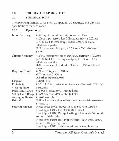
2.0 THERMALERT GP MONITOR
2.1 SPECIFICATIONS
The following sections cover thermal, operational, electrical, and physicalspecifications for each model.
2.1.1 Operational
Input Accuracy: 0-5V input resolution 1mV, accuracy ± 2mV4-20mA input resolution 0.01mA, accuracy ± 0.02mAJ, K, E, N, T thermocouple input, ± 0.5% or ± 2°C,whichever is greaterR, S thermocouple input, ± 0.5% or ± 3°C, whichever isgreater
Output Accruacy: 4-20mA output resolution 0.014mA, accuracy ± 0.02mAJ, K, E, N, T thermocouple output, ± 0.5% or ± 2°C,whichever is greaterR, S thermocouple output, ± 0.5% or ± 4°C, whichever isgreater
Response Time: GPR/GPS (system): 300msGPM (system): 400msAll other inputs: 200ms
Display: 4 digit LEDEmissivity: 0.10 to 1.09 (adjustable in 0.01 increments-H001 and H002 only) Warmup time: 5 secondsPeak Hold Range: 0 to 998 seconds (999=infinite hold)Valley Hold Range: 0 to 998 seconds (999=infinite hold)Averaging Range: 0 to 60 secondsFail-safe: Full or low scale, depending upon system failure (refer to
Section 3.2)Setpoint Ranges: Head Types H001, H002: -18 to 538°C (0 to 1000°F)
Head Type H003: 0 to 500°C (32 to 932°F)Head Type H004: 0V input setting = low scale, 5V inputsetting = high scaleHead Type H005: 4mA input setting = low scale, 20mAinpute setting = high scaleHead Type H006: scale = input thermocouple range

Thermalert GP Series Operator’s Manual 3
Thermocouple J-type: -40 to 750°C (-40 to 1382°F)Measurement Range K-type: -40 to 1250°C (-40 to 2282°F)
E-type: -40 to 700°C (-40 to 1292°F)N-type: -40 to 1300°C (-40 to 2372°F)R-type: 0 to 1750°C (32 to 3182°F)S-type: 0 to 1750°C (32 to 3182°F)T-type: -100 to 350°C (-148 to 662°F)
2.1.2 Electrical
Power: 110 - 220VAC ±20%, 50-60Hz, 100mA
Analog Output: 4 to 20mA
Thermocouple Output J-type: -40 to 750°C (-40 to 1382°F)K-type: -40 to 1250°C (-40 to 2282°F)E-type: -40 to 700°C (-40 to 1292°F)N-type: -40 to 1300°C (-40 to 2372°F)R-type: 0 to 1750°C (32 to 3182°F)S-type: 0 to 1750°C (32 to 3182°F)T-type: -100 to 350°C (-148 to 662°F)
Max loop impedance: 350 Ω
2 setpoints output: CMOS Level Hi/Lo (~5V/0V)(SP1, SP2–15mA@ 5V)
Mechanical Relays AC Contact: 250VAC, 3A(Optional) DC Contact: 30VDC, 3A
2.1.3 Physical
Dimensions: 1/8 DIN, 118mm length (1.75 in x 3.63 in x 4.75 in)
Weight: 320 grams (0.7 lbs)
Environmental Rating: NEMA-12 (IEC 529, IP 54) front panel only
Ambient Operating Temperature Range: 0 to 50°C (32 to 122°F)
Relative Humidity: 10-95%, non-condensing (with Gpm head at <30°C (86°F))
Storage Temperature: -30 to 65°C (-22 to 150°F)
4 Thermalert GP Series Operator’s Manual
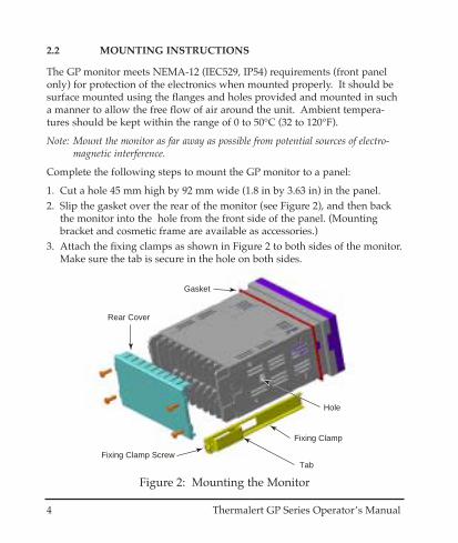
2.2 MOUNTING INSTRUCTIONS
The GP monitor meets NEMA-12 (IEC529, IP54) requirements (front panelonly) for protection of the electronics when mounted properly. It should besurface mounted using the flanges and holes provided and mounted in sucha manner to allow the free flow of air around the unit. Ambient tempera-tures should be kept within the range of 0 to 50°C (32 to 120°F).
Note: Mount the monitor as far away as possible from potential sources of electro-magnetic interference.
Complete the following steps to mount the GP monitor to a panel:
1. Cut a hole 45 mm high by 92 mm wide (1.8 in by 3.63 in) in the panel.2. Slip the gasket over the rear of the monitor (see Figure 2), and then back
the monitor into the hole from the front side of the panel. (Mountingbracket and cosmetic frame are available as accessories.)
3. Attach the fixing clamps as shown in Figure 2 to both sides of the monitor.Make sure the tab is secure in the hole on both sides.
Gasket
Hole
Fixing Clamp
TabFixing Clamp Screw
Rear Cover
Figure 2: Mounting the Monitor

4. Secure the monitor to the panel by tightening both fixing clamp screwsuntil the flanges are snug against the back surface of the panel.
5. Connect the terminal cable as described in the following section.6. After you complete the electrical installation, secure the rear cover to the
back of the monitor. (Do not operate with rear cover removed because ofelectrical shock hazard.)
2.3 ELECTRICAL INSTALLATION
2.3.1 Terminal Block Layout
The terminal block layout is shown in Figure 3. (Terminal definitions are onthe following page.)
SP1 SP2 RST NC Power
+ + + N H
+ + + +
mA out TC out Input 1 Input 2 SHD 24V Input3
Figure 3: Terminal Block Layout
Thermalert GP Series Operator’s Manual 5
6 Thermalert GP Series Operator’s Manual
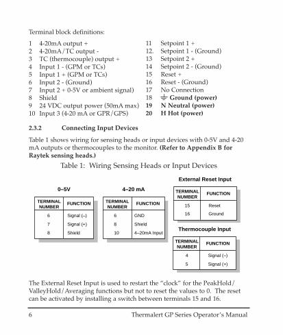
2.3.2 Connecting Input Devices
Table 1 shows wiring for sensing heads or input devices with 0-5V and 4-20mA outputs or thermocouples to the monitor. (Refer to Appendix B forRaytek sensing heads.)
The External Reset Input is used to restart the “clock” for the PeakHold/ValleyHold/Averaging functions but not to reset the values to 0. The resetcan be activated by installing a switch between terminals 15 and 16.
Table 1: Wiring Sensing Heads or Input Devices
6
7
8
Signal (–)
Signal (+)
Shield
TERMINALNUMBER
FUNCTION
0–5V
6
8
10
GND
Shield
4–20mA Input
TERMINALNUMBER
FUNCTION
4–20 mA TERMINALNUMBER
FUNCTION
15
16
Reset
Ground
External Reset Input
TERMINALNUMBER
FUNCTION
4
5
Signal (–)
Signal (+)
Thermocouple Input
Terminal block definitions:
1 4-20mA output +2 4-20mA/TC output -3 TC (thermocouple) output +4 Input 1 - (GPM or TCs)5 Input 1 + (GPM or TCs)6 Input 2 - (Ground)7 Input 2 + 0-5V or ambient signal)8 Shield9 24 VDC output power (50mA max)10 Input 3 (4-20 mA or GPR/GPS)
11 Setpoint 1 +12. Setpoint 1 - (Ground)13 Setpoint 2 +14 Setpoint 2 - (Ground)15 Reset +16 Reset - (Ground)17 No Connection18 Ground (power)19 N Neutral (power)20 H Hot (power)

Thermalert GP Series Operator’s Manual 7
18
19
20
Ground
Neutral
Hot
TERMINALNUMBER
FUNCTION
Table 3: Power Connections
Table 2: Wiring Devices that Use Power from Monitor
6
6
7
8
9
Power (-)
Signal (-)
Signal (+)
Shield
Power (+)
TERMINALNUMBER
FUNCTION
6
6
8
9
10
Power (-)
4-20mA (-)
Shield
Power (+)
4-20mA (+)
TERMINALNUMBER
FUNCTION
0-5V 4-20 mA
8
9
10
Shield
Power (+)
4-20mA (-)
TERMINALNUMBER
FUNCTION
2-Wire 4-20 mA
WARNING1. Incorrect wiring can damage the monitor and void the warranty.
Make sure to unplug the unit before wiring devices or power.
2. The unit be used in a closed cabinet to prevent electrical shock!
Refer to Section 2.4.2 for information on setting up parameters on the GPMonitor for 0-5 volt, 4-20 mA devices and thermocouples.
2.3.3 Power Connections
You can connect 110-220VAC, 50-60Hz, to the monitor. It can automaticallysense whether you connect 110 or 220 VAC. Use Table 3 as a guide.
Use Table 2 when connecting either 0-5V or 4-20mA input devices that canuse the 24VDC/50mA power available from the monitor.

8 Thermalert GP Series Operator’s Manual
2.3.5 Relay Accessory
A solid state relay accessory is available as a switching output for Setpointuse as a control for an alarm or triggering mechanism. The Thermalert GPSetpoint output can supply 15mA @ 5V for SSR control. A wiring diagramfor the relay accessory is shown in Figure 4.
Figure 4: Relay Accessory Wiring
To GP MonitorTerminal 11 or 13(Setpoint 1 or 2)
To GP MonitorTerminal 12 or 14(Digital Ground)
To Alarm orControlling Device
Two relays are necessary to take advantage of both setpoints.
Table 4: Output Connections
TERMINALNUMBER
FUNCTION
11
12
13
14
Digital ground
Setpoint 1
Digital ground
Setpoint 2
Setpoints 1 & 2
1
2
8
4-20mA output
Analog ground
Shield
TERMINALNUMBER
FUNCTION TERMINALNUMBER
FUNCTION
11
12
13
14
Optional Dual Relays4-20 mA
TERMINALNUMBER
FUNCTION
2
3
Thermocouple -
Thermocouple +
Thermocouple
2.3.4 Output Connections
The monitor has the following outputs (connections shown in Table 4): • 4 – 20mA• Thermocouple outputs (J, K, E, N, T, R, and S)• Setpoints 1 and 2

The “N” indicator, on the left side of the panel, when lit, shows that the unitis working normally. The “O” and “L” indicators are controlled by Setpoints1 and 2 (SP1, SP2). The “O” indicator, when lit, shows that the measuredtemperature or value exceeds the current SP1 or SP2 setting. The “L” indica-tor, when lit, indicates that the measured temperature or value is lower thanthe current SP1 or SP2 setting.
On the right side of the panel are two indicators that show which tempera-ture value the unit is set to if temperature sensors are attached to the moni-tor. The “C” indicates if the temperature measurement is in degrees C(Celsius). The “F” indicates if the temperature measurement is in degrees F(Fahrenheit). For 0-5 volt and 4-20 mA devices that do not measure tempera-tures, C and F can both be turned off.
Thermalert GP Series Operator’s Manual 9
2.4 OPERATION
The Thermalert GP Monitor consists of a control panel with 4 LEDs, 3 but-tons, and 5 indicating lights. Besides displaying the current temperature oruser-defined value, the LEDs also display parameter settings. By using the “I”key and the up and down arrow keys you can control the different functions,and the indicator LEDs show the function being addressed. Figure 5 showsthe startup screen when power is first turned on (no information stored onEEPROM), or when factory defaults are restored (see Section 2.4.12).
ONL
CF
Thermalert GP
Figure 5: The Control Panel Startup Screen

10 Thermalert GP Series Operator’s Manual
2.4.1 Display/Key Pad
Before turning on the power, make sure all wiring connections are secure.Table 5 shows the factory-set default values.
Note that all controls can be adjusted while the power is on without damag-ing sensor or electronics.
Table 5: Factory-set Default Values
Emissivity
Sensing Head/DeviceNumber
Display Resolution
Setpoints (SP1, SP2)
Peak Hold
Valley Hold
Averaging
Ambient TemperatureCompensation (t-amb)
Offset
0.10 - 1.09in 0.01 increments
H001 - H006
0 - 4
According to sensinghead/device type
0 - 998 seconds999 = infinite hold
0 - 998 seconds999 = infinite hold
0 - 60 seconds
-18 to 1200°C(0 to 2200°F)
-50 to 50°C(-99 to 99°F)
For 0 - 5V and 4 - 20 mA &thermocouple input, is not functional
See Section 2.4.2
See Sections 2.4.2 and 2.4.4
Infinite reset by hardware
Infinite reset by hardware
0.95
H001
0
off
0
0
0
0
0
PARAMETERS SETTING RANGE REMARKSDEFAULTVALUES
Thermalert GP Series Operator’s Manual 11
ONL
CF
Thermalert GP
Figure 6: Device Selection Display
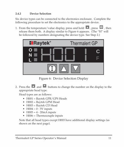
2.4.2 Device Selection
Six device types can be connected to the electronics enclosure. Complete thefollowing procedure to set the electronics to the appropriate device.
1. From the temperature/value display, press and hold , press , thenrelease them both. A display similar to Figure 6 appears. (The “H” willbe followed by numbers designating the device type. See Step 2.)
2. Press the and buttons to change the number on the display to theappropriate head type.Head types are as follows:
• H001 = Raytek GPR/GPS Heads• H002 = Raytek GPM Head• H003 = Raytek CI3 Head• H004 = 0 - 5V inputs• H005 = 4 - 20mA inputs• H006 = Thermocouple inputs
Note that all head types except H003 have additional display settings (asshown on the next page).

12 Thermalert GP Series Operator’s Manual
H001/H002If H001 or H002 are displayed, press the button once to be able toturn the decimal Off (“0”) or On (“1”). A “d” is displayed on the monitor.When the decimal is On, it will be positioned at a tenth of a degree (forexample, 888.8). For H001, press the button again to return to thetemperature display.
For H002, press the button to be able to adjust the sensor’s detectorcalibration value (“D” value) by using the up and down arrows.
Press once more to adjust the ambient calibration value (“R” value).
H003The sensor attached as H003 has a fixed emissivity and no additionalmonitor adjustments are necessary.
H004/H005If H004 or H005 are displayed, press the button once to turn the deci-mal Off or to set the location of the decimal on the display. Use the follow-ing as a guide:• d = 0 Decimal turned Off• d = 1 Decimal located at ones position (for example, 8888.)• d = 2 Decimal located at tens position (for example, 888.8)• d = 3 Decimal located at hundreds position (for example, 88.88)• d = 4 Decimal located at thousands position (for example, 8.888)
Both H004 and H005 have additional settings as follows:
For H004, press the button again to be able to adjust the 0 volt equiv-alent value (using the up and down arrows). Press once more toadjust the 5 volt equivalent value.
H005For H005, press the button again to be able to adjust the 4mA equiva-
lent value (using the up and down arrows). Press once more toadjust the 20mA equivalent value.
Thermalert GP Series Operator’s Manual 13
H006
For H006, press the button once to be able to turn the decimal Off(“0”) or On (“1”). A “d” is displayed on the monitor. When the decimal isOn, it will be positioned at a tenth of a degree (e.g., 888.8). Press thebutton again to be able to select the thermocouple input type. Use the fol-lowing as a guide:
• TC1 = J-type thermocouple input• TC2 = K-type thermocouple input• TC3 = E-type thermocouple input• TC4 = N-type thermocouple input• TC5 = R-type thermocouple input• TC6 = S-type thermocouple input• TC7 = T-type thermocouple input
3. Press the button until the temperature or user-defined value displays.
14 Thermalert GP Series Operator’s Manual
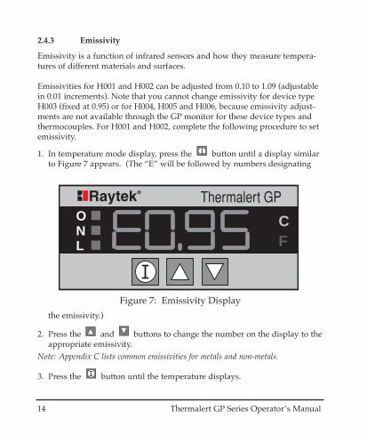
2.4.3 Emissivity
Emissivity is a function of infrared sensors and how they measure tempera-tures of different materials and surfaces.
Emissivities for H001 and H002 can be adjusted from 0.10 to 1.09 (adjustablein 0.01 increments). Note that you cannot change emissivity for device typeH003 (fixed at 0.95) or for H004, H005 and H006, because emissivity adjust-ments are not available through the GP monitor for these device types andthermocouples. For H001 and H002, complete the following procedure to setemissivity.
1. In temperature mode display, press the button until a display similarto Figure 7 appears. (The “E” will be followed by numbers designating
ONL
CF
Thermalert GP
Figure 7: Emissivity Display
the emissivity.)
2. Press the and buttons to change the number on the display to theappropriate emissivity.
Note: Appendix C lists common emissivities for metals and non-metals.
3. Press the button until the temperature displays.
Thermalert GP Series Operator’s Manual 15
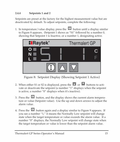
2. When either S1 or S2 is displayed, press the or buttons to acti-vate or deactivate the setpoint (a number “1” displays when the setpointis active, a number “0” displays when it’s inactive).
3. Press the button, and the display shows the current alarm tempera-ture or value (Setpoint value). Use the up and down arrows to adjust thealarm value.
4. Press the button again and a display similar to Figure 9 appears. Ifyou see a number “1,” it means the Normally Low setpoint will changestate when the target temperature or value exceeds the alarm value. If anumber “0” displays, the Normally Low setpoint will change state whenthe target temperature or value is lower than the setpoint alarm value.
2.4.4 Setpoints 1 and 2
Setpoints are preset at the factory for the highest measurement value but aredeactivated by default. To adjust setpoints, complete the following:
1. In temperature/value display, press the button until a display similarto Figure 8 appears. (Setpoint 1 shows as “S1” followed by a number 0,showing that Setpoint 1 is Inactive, or a number 1, designating active.
ONL
CF
Thermalert GP
Figure 8: Setpoint Display (Showing Setpoint 1 Active)

16 Thermalert GP Series Operator’s Manual
Figure 10: Output Examples
SP1
DB
Signal
SP1=90DB=5
GP Monitor Display= b 0 Trigger Signal Low, Output Normally Low
L
If you see a number “3,” it means the Normally High setpoint will changestate when the target temperature or value exceeds the alarm value. If anumber “2” displays, the Normally High setpoint will change state whenthe target temperature or value is lower than the setpoint alarm value.
Note that the “O” and “L” indicators on the monitor are controlled by SP1and SP2. The “L” lights when the input signal has fallen below either theSP1 or SP2 value and when the trigger level (“b”) is set to either “0” or“2”. The “O” indicator lights when the input signal has risen above eitherthe SP1 or SP2 value and when the trigger level (“b”) is set to either “1” or“3”. Figure 10 (below and continued on next page) shows examples ofhow the setpoints change state when triggered.
ONL
CF
Thermalert GP
Figure 9: Setpoint Alarm (Trigger) Display

Thermalert GP Series Operator’s Manual 17
SP1
DB
Signal
SP1=90DB=5
GP Monitor Display= b 1 Trigger Signal High, Output Normally Low
SP1
DB
Signal
SP1=90DB=5
GP Monitor Display= b 2 Trigger Signal Low, Output Normally High
SP1
DB
Signal
SP1=90DB=5
GP Monitor Display= b 3 Trigger Signal High, Output Normally High
L
O
O
18 Thermalert GP Series Operator’s Manual
ONL
CF
Thermalert GP
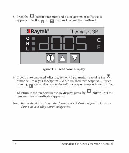
Figure 11: Deadband Display
5. Press the button once more and a display similar to Figure 11appears. Use the or buttons to adjust the deadband.
6. If you have completed adjusting Setpoint 1 parameters, pressing the button will take you to Setpoint 2. When finished with Setpoint 2, if used,pressing again takes you to the 4-20mA output setup indicator display.
To return to the temperature/value display, press the button until thetemperature/value display appears.
Note: The deadband is the temperature/value band (±) about a setpoint, wherein analarm output or relay cannot change state.
Thermalert GP Series Operator’s Manual 19
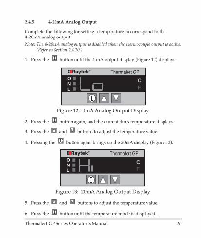
2.4.5 4-20mA Analog Output
Complete the following for setting a temperature to correspond to the 4-20mA analog output:
Note: The 4-20mA analog output is disabled when the thermocouple output is active.(Refer to Section 2.4.10.)
1. Press the button until the 4 mA output display (Figure 12) displays.
2. Press the button again, and the current 4mA temperature displays.
3. Press the and buttons to adjust the temperature value.
4. Pressing the button again brings up the 20mA display (Figure 13).
5. Press the and buttons to adjust the temperature value.
6. Press the button until the temperature mode is displayed.
ONL
CF
Thermalert GP
Figure 12: 4mA Analog Output Display
ONL
CF
Thermalert GP
Figure 13: 20mA Analog Output Display
20 Thermalert GP Series Operator’s Manual
FUNCTION ˚C ˚F
1001
0101
˚C lit on monitor˚F lit on monitorTo disable C/ F indicators (only for H004 & H005)Not available
ONL
CF
Thermalert GP
Figure 14: Degrees C Activation Display
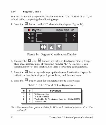
2.4.6 Degrees C and F
You can change the temperature display unit from °C to °F, from °F to °C, orto both off by completing the following steps:
1. Press the button until a “C” shows in the display (Figure 14).
2. Pressing the and buttons activates or deactivates °C as a temper-ature measurement unit. If you select number “1,” °C is active; if youselect number “0,” it is inactive. See Table 6 for setting configurations.
3. Press the button again brings up the degrees F activation display. Toactivate or deactivate degrees F, press the up and down arrows.
4. Press the button until the temperature mode is displayed.
Table 6: The °C and °F Configurations
Note: Thermocouple output is available for H004 and H005 only if either °C or °F isactivated.

Thermalert GP Series Operator’s Manual 21
2.4.7 Peak Hold, Valley Hold, and Average
The Peak Hold,Valley Hold, and Average times are factory set at 0 secondsand are not activated. If you don’t need to use these signal processing func-tions, no adjustments are necessary.
Note: Only one signal processing setting can be active at a time.
To set and activate, complete the following steps:
1. Press and hold the button and press the button and release themboth. The Peak Hold display appears (Figure 15).
2. Press the button again and the display shows the current Peak Holdvalue in seconds.
3. Set the display by using the and buttons. Note that “000” turnsoff Peak Hold.
4. Press the button again and the Valley Hold display (Figure 16)appears.
ONL
CF
Thermalert GP
Figure 15: Peak Hold Display

22 Thermalert GP Series Operator’s Manual
ONL
CF
Thermalert GP
Figure 16: Valley Hold Display
ONL
CF
Thermalert GP
Figure 17: Averaging Display
5. Press the button once more and the display shows the current ValleyHold value in seconds.
6. Set the display by using the and buttons. Note that “000” turnsoff Valley Hold.
7. Press the button again and the Averaging display (Figure 17) appears.
8. Press the button once more and the display shows the currentAveraging value in seconds.

Thermalert GP Series Operator’s Manual 23
Figure 18: Ambient Temperature Compensation Display
9. Set the display by using the and buttons. Note that “000” turnsoff Averaging.
10.Press the button until the temperature mode is displayed.
2.4.8 Ambient Temperature Compensation (T-Ambient)
Head types H001 and H002 only - The ambient temperature compensation isfactory preset as inactive. This value is normal for most applications.However, in some applications the surrounding ambient temperature ismuch higher than the target. If the target has an emissivity less than 1.0, itwill reflect a certain portion of the surrounding energy and cause an erro-neous temperature reading. To avoid this error, set in the average surround-ing temperature and the microprocessor will automatically compensate for it.
To set T-Ambient, complete the following:
1. Press and hold the button, and press the button, then releasethem both. The Peak Hold display appears (as shown in Figure 15).
2. Press the button several times until the Ambient Compensation indi-cator displays (Figure 18). The display shows either a “0” or “1” (default=“0” - Off).
3. You can activate or deactivate Ambient Temperature Compensation byusing the up and down buttons. A number “1” means it is active; a num-ber “0” means it is inactive.
ONL
CF
Thermalert GP

3. To adjust the display and output offset, press the button once more.
4. Set the display by using the and buttons.
5. Press the button until the temperature mode displays.
24 Thermalert GP Series Operator’s Manual
4. To adjust the ambient temperature compensation, press the buttononce more.
5. Set the value by using the and buttons.
6. Press the button until the temperature/value mode displays.
2.4.9 Display and Analog Output Offset
To adjust and set the Display and Analog Output Offset (applies to displayedtemperature and all analog outputs), complete the following steps:
1. Press the button and the button simultaneously then release. ThePeak Hold display appears (as shown in Figure 15).
2. Press the button several times until the Offset indicator displays(Figure 19).
ONL
CF
Thermalert GP
Figure 19: Offset Indicator Display

Thermalert GP Series Operator’s Manual 25
2.4.10 Thermocouple Output
Thermocouple output is factory preset as inactive. To adjust and set the typeof thermocouple output, complete the following steps:
1. Press and hold the button, and press the button, then releasethem both. The Peak Hold display appears (as shown in Figure 15).
2. Press the button several times until the thermocouple output indica-tor displays as shown in Figure 20.
ONL
CF
Thermalert GP
Figure 20: Thermocouple Output
3. Press the and buttons to change the number on the display to theappropriate thermocouple output type. Use the following as a guide:
4. Press the button until the temperature/value mode displays.Notes: Thermocouple output is available for H004 and H005 inputs only if either °C
or °F is activated.The 4-20mA analog output is disabled when the thermocouple output isactive.
• TC1 = J-type thermocouple output• TC2 = K-type thermocouple output• TC3 = E-type thermocouple output• TC4 = N-type thermocouple output
• TC5 = R-type thermocouple output• TC6 = S-type thermocouple output• TC7 = T-type thermocouple output

26 Thermalert GP Series Operator’s Manual
2.4.11 Lockout Mode
The Lockout Mode protects you from accidental value changes or from tam-pering. When you activate lockout, no mode values can be changed.
To activate Lockout, complete the following step:
Press and hold the button, press the button 3 times, then release.The letter “L” appears on the display for approximately 3 seconds show-ing that Lockout has been activated.
To deactivate Lockout, complete the following steps:
1. Press the button once to get the emissivity adjustment display.
2. Press the button, the button 3 times, then release. The letter “E”displays for approximately 3 seconds showing that Lockout has beendeactivated.
3. Press the button until the temperature mode displays.
2.4.12 Factory Defaults
If you need to reset the Thermalert GP monitor to its factory default settings,you can do so by pressing and holding the button and then pressing the
button 3 times.

No output
Erroneous output
Erroneous Temperature
Erroneous Temperature
Erroneous Temperature
Erroneous Temperature
Erroneous Temperature
Relays "chatter"
No power to monitor
Wrong output range
Faulty sensor cable
Field of view obstructed
Lens dirty
Wrong emissivity
Wrong signal
Deadband too narrow
Check power supply
Correct Lo/Hi output setting
Verify cable integrity
Remove obstruction
Clean lens (see Section 5.3)
Correct emissivity setting
Correct peak/valley setting
Correct deadband setting
SYMPTOM PROBABLE CAUSE SOLUTION
Thermalert GP Series Operator’s Manual 27
3.0 MAINTENANCE
Our customer service representatives are always at your disposal for ques-tions regarding application assistance, calibration, repair, and solutions tospecific problems. Our Service Department should be contacted beforereturning any equipment to us. In many cases, problems can be solved overthe telephone.
3.1 TROUBLESHOOTING MINOR PROBLEMS
Table 7 lists common symptoms, their causes, and possible solutions. If youare experiencing a problem that is not listed below, please call our ServiceDepartment. Phone numbers are listed on the Warranty/Copyright page atthe beginning of this manual.
Table 7: Troubleshooting
28 Thermalert GP Series Operator’s Manual
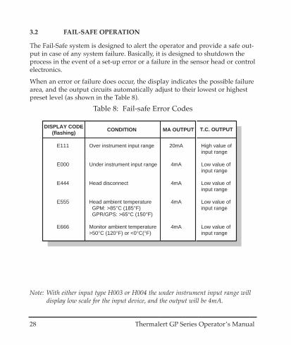
3.2 FAIL-SAFE OPERATION
The Fail-Safe system is designed to alert the operator and provide a safe out-put in case of any system failure. Basically, it is designed to shutdown theprocess in the event of a set-up error or a failure in the sensor head or controlelectronics.
When an error or failure does occur, the display indicates the possible failurearea, and the output circuits automatically adjust to their lowest or highestpreset level (as shown in the Table 8).
Table 8: Fail-safe Error Codes
20mA
4mA
4mA
4mA
4mA
E111
E000
E444
E555
E666
Over instrument input range
Under instrument input range
Head disconnect
Head ambient temperature GPM: >85°C (185°F) GPR/GPS: >65°C (150°F)
Monitor ambient temperature>50°C (120°F) or <0°C(°F)
High value ofinput range
Low value of input range
Low value of input range
Low value of input range
Low value of input range
DISPLAY CODE(flashing)
CONDITION MA OUTPUT T.C. OUTPUT
Note: With either input type H003 or H004 the under instrument input range willdisplay low scale for the input device, and the output will be 4mA.
Thermalert GP Series Operator’s Manual 29
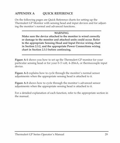
APPENDIX A QUICK REFERENCE
On the following pages are Quick Reference charts for setting up theThermalert GP Monitor with sensing head and input devices and for adjust-ing the monitor’s normal and advanced functions.
WARNINGMake sure the device attached to the monitor is wired correctlyor damage to the monitor and attached units could occur. Referto the appropriate Sensing Head and Input Device wiring chartin Section 2.3.2, and the appropriate Power Connections wiringchart in Section 2.3.3 before continuing.
Figure A-1 shows you how to set up the Thermalert GP monitor for yourparticular sensing head or for your 0–5 volt, 4–20mA, or thermocouple inputdevice.
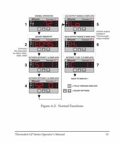
Figure A-2 explains how to cycle through the monitor’s normal sensoradjustments when the appropriate sensing head is attached to it.
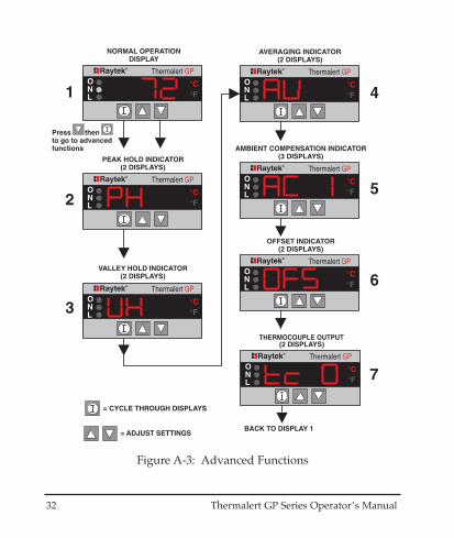
Figure A-3 shows how to cycle through the monitor’s advanced sensoradjustments when the appropriate sensing head is attached to it.
For a detailed explanation of each function, refer to the appropriate section inthe manual.

30 Thermalert GP Series Operator’s Manual
Figure A-1: Head and Input Setup
Thermalert GP Series Operator’s Manual 31
EmissivityNot Adjustable
for H003, H004,H005, H006
4/20mA outputsdisabled ifThermocoupleoutput enabled
Figure A-2: Normal Functions
32 Thermalert GP Series Operator’s Manual
Figure A-3: Advanced Functions
Thermalert GP Series Operator’s Manual 33
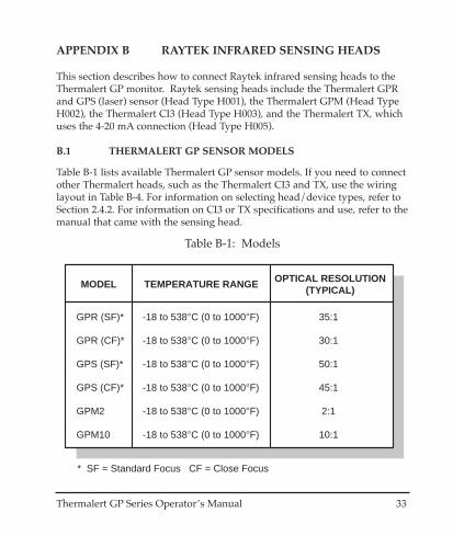
APPENDIX B RAYTEK INFRARED SENSING HEADS
This section describes how to connect Raytek infrared sensing heads to theThermalert GP monitor. Raytek sensing heads include the Thermalert GPRand GPS (laser) sensor (Head Type H001), the Thermalert GPM (Head TypeH002), the Thermalert CI3 (Head Type H003), and the Thermalert TX, whichuses the 4-20 mA connection (Head Type H005).
B.1 THERMALERT GP SENSOR MODELS
Table B-1 lists available Thermalert GP sensor models. If you need to connectother Thermalert heads, such as the Thermalert CI3 and TX, use the wiringlayout in Table B-4. For information on selecting head/device types, refer toSection 2.4.2. For information on CI3 or TX specifications and use, refer to themanual that came with the sensing head.
GPR (SF)*
GPR (CF)*
GPS (SF)*
GPS (CF)*
GPM2
GPM10
35:1
30:1
50:1
45:1
2:1
10:1
-18 to 538°C (0 to 1000°F)
-18 to 538°C (0 to 1000°F)
-18 to 538°C (0 to 1000°F)
-18 to 538°C (0 to 1000°F)
-18 to 538°C (0 to 1000°F)
-18 to 538°C (0 to 1000°F)
MODEL TEMPERATURE RANGE OPTICAL RESOLUTION(TYPICAL)
* SF = Standard Focus CF = Close Focus
Table B-1: Models
34 Thermalert GP Series Operator’s Manual
Thermalert GPR/GPS Thermalert GPM
6
7
8
9
10
Black
Green
Bare
Red
White
TERMINALNUMBER
WIRE COLOR
4
5
6
7
8
Green
Yellow
White
Brown
Bare
TERMINALNUMBER
WIRE COLOR
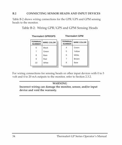
Table B-2: Wiring GPR/GPS and GPM Sensing Heads
B.2 CONNECTING SENSOR HEADS AND INPUT DEVICES
Table B-2 shows wiring connections for the GPR/GPS and GPM sensingheads to the monitor.
For wiring connections for sensing heads or other input devices with 0 to 5volt and 4 to 20 mA outputs to the monitor, refer to Section 2.3.2.
WARNINGIncorrect wiring can damage the monitor, sensor, and/or inputdevice and void the warranty.
Thermalert GP Series Operator’s Manual 35
6
6
7
8
9
Power Supply -
Signal Ground
Signal +
Shield
Power Supply +
TERMINALNUMBER
FUNCTION
CI3
8
9
10
Shield
TX (+)
TX (-)
TERMINALNUMBER
FUNCTION
TX
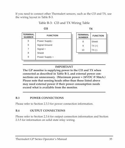
Table B-3: CI3 and TX Wiring Table
If you need to connect other Thermalert sensors, such as the CI3 and TX, usethe wiring layout in Table B-3.
IMPORTANTThe GP monitor is supplying power to the CI3 and TX whenconnected as described in Table B-3, and external power con-nections are unnecessary. (Maximum power = 24VDC @ 50mA.)Please note that sensing heads other than those listed abovemay need external power if their power consumption needsexceed what is available from the monitor.
B.3 POWER CONNECTIONS
Please refer to Section 2.3.3 for power connection information.
B.4 OUTPUT CONNECTIONS
Please refer to Section 2.3.4 for output connection information and Section2.3.5 for information on solid state relay wiring.
36 Thermalert GP Series Operator’s Manual
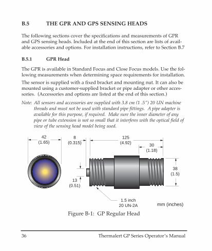
42(1.65)
125(4.92)
8(0.315)
13(0.51)
1.5 inch20 UN-2A
38(1.5)
30(1.18)
mm (inches)
Figure B-1: GP Regular Head
B.5 THE GPR AND GPS SENSING HEADS
The following sections cover the specifications and measurements of GPRand GPS sensing heads. Included at the end of this section are lists of avail-able accessories and options. For installation instructions, refer to Section B.7
B.5.1 GPR Head
The GPR is available in Standard Focus and Close Focus models. Use the fol-lowing measurements when determining space requirements for installation.
The sensor is supplied with a fixed bracket and mounting nut. It can also bemounted using a customer-supplied bracket or pipe adapter or other acces-sories. (Accessories and options are listed at the end of this section.)
Note: All sensors and accessories are supplied with 3.8 cm (1 .5”) 20 UN machinethreads and must not be used with standard pipe fittings. A pipe adapter isavailable for this purpose, if required. Make sure the inner diameter of anypipe or tube extension is not so small that it interferes with the optical field ofview of the sensing head model being used.
Thermalert GP Series Operator’s Manual 37
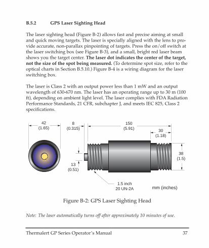
B.5.2 GPS Laser Sighting Head
The laser sighting head (Figure B-2) allows fast and precise aiming at smalland quick moving targets. The laser is specially aligned with the lens to pro-vide accurate, non-parallax pinpointing of targets. Press the on/off switch atthe laser switching box (see Figure B-3), and a small, bright red laser beamshows you the target center. The laser dot indicates the center of the target,not the size of the spot being measured. (To determine spot size, refer to theoptical charts in Section B.5.10.) Figure B-4 is a wiring diagram for the laserswitching box.
The laser is Class 2 with an output power less than 1 mW and an outputwavelength of 630-670 nm. The laser has an operating range up to 30 m (100ft), depending on ambient light level. The laser complies with FDA RadiationPerformance Standards, 21 CFR, subchapter J, and meets IEC 825, Class 2specifications.
42(1.65)
150(5.91)
8(0.315)
13(0.51)
1.5 inch20 UN-2A
38(1.5)
30(1.18)
mm (inches)
Figure B-2: GPS Laser Sighting Head
Note: The laser automatically turns off after approximately 10 minutes of use.

38 Thermalert GP Series Operator’s Manual
WARNINGAvoid exposure to laser light. Eye damage can result. Useextreme caution when operating. Never point at a person.
CAUTIONCAUTION
SENSORLaser Switching Box
Laser On/Off Switch
LAS
ER
LIG
HT
DO
NO
T S
TA
RE
INT
O B
EA
MLA
SE
R C
LAS
S II
<1M
w /
630-
670n
mIE
C 8
25/9
3
LASER RADIATION - DO NOT STARE INTO BEAM
OUTPUT < 1mW WAVELENGTH 630 - 670 nm
CLASS II LASER PRODUCT
AVOID EXPOSURE - LASER RADIATIONIS EMITTED FROM THIS APERATURE
COMPLIESWITH CFR1040.10
Figure B-3: Laser Sighting Head and Switching Box
4 61 2 43 57
1. Cap2. Plastic compression fitting3. Rubber washer4. Metal washer5. Cable shield6. Wires7. Sensor head cable
Monitor cable(8m/26ft length)
Sensor head cable(4m/13ft length)
Sensor head wires (left to right):red, blue, green, white, yellow
Monitor wires (left to right):white, green, black, red
Figure B-4: Laser Switching Box Wiring Diagram

Thermalert GP Series Operator’s Manual 39
The fixed bracket (Figure B-5) is supplied with the sensing head.
51(2.0)
89(3.5)
57 REF(2.25)
φ 39(1.52)
R 32(1.25)
76(3.0)
64(2.5)
R 29(1.15)
φ 6(0.25)
13(0.5)
6 (0.25)mm (inches)
Figure B-5: Fixed Mounting Bracket
48 119(4.75)
94(3.75)
56 REF(2.25)
φ 37.5(1.5)
R 31(1.25)
120(4.8)
100(4)
102(4.063)
48
77(3.063)
93(3.69)
7(.28)
102(4.063)
φ 6(.25)
mm (inches)
Figure B-6: Adjustable Mounting Bracket
B.5.3 Adjustable Mounting Bracket Accessory
An adjustable mounting bracket is available if you require a sensor that canbe aimed at different targets from the same mounted position.

40 Thermalert GP Series Operator’s Manual
125(4.92)
1.5 inch20 UN-2ATHREAD
1/8" NPT NIPPLE(2 PLCS)
53(2.1)
23(0.9)
51(2.01)
63(2.48)
22(0.87)
mm (inches)
Figure B-7: GPR Head with Air/Water-cooled Housing
B.5.4 GPR & GPS Head with Air/Water-cooled Housing
The air/water-cooled housing option allows the sensor to be used in ambienttemperatures up to 120°C (250°F) for air-cooled and 177°C (350°F) for water-cooled. It is supplied with two 1/8” NPT brass fittings. Air flow should be25°C (77°F) at 2.8 liters/sec (6 cfm) with a pressure drop across the housingof 0.63 Kg/cm2 (9 PSID). Water flow should be approximately 2 liters (0.5gallons) per minute. Water temperature should be 10-27°C (50-80°F) for effi-cient cooling. Using chilled water below 10°C (50°F) is not recommended.To avoid condensation, it is recommended to use the Air Purge Collar withthe Water Cooled Housing.
Figure B-8: GPS Head with Air/Water-cooled Housing
150(5.91)
1.5 inch20 UN-2ATHREAD
1/8" NPT NIPPLE(2 PLCS)
53(2.1)
23(0.9)
76(3)
63(2.48)
22(0.87)
mm (inches)
Thermalert GP Series Operator’s Manual 41
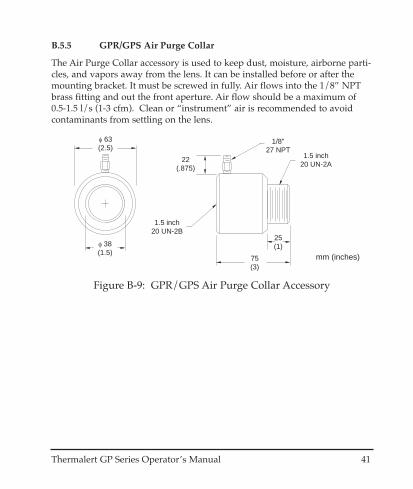
B.5.5 GPR/GPS Air Purge Collar
The Air Purge Collar accessory is used to keep dust, moisture, airborne parti-cles, and vapors away from the lens. It can be installed before or after themounting bracket. It must be screwed in fully. Air flows into the 1/8” NPTbrass fitting and out the front aperture. Air flow should be a maximum of0.5-1.5 l/s (1-3 cfm). Clean or “instrument” air is recommended to avoidcontaminants from settling on the lens.
φ 38(1.5)
φ 63(2.5)
1/8"27 NPT
1.5 inch20 UN-2B
1.5 inch20 UN-2A
75(3)
22(.875)
25(1)
mm (inches)
Figure B-9: GPR/GPS Air Purge Collar Accessory
42 Thermalert GP Series Operator’s Manual
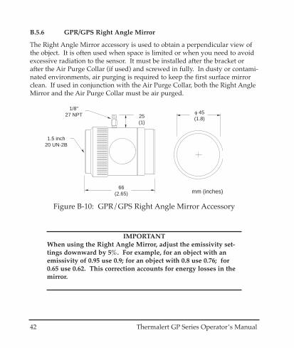
IMPORTANTWhen using the Right Angle Mirror, adjust the emissivity set-tings downward by 5%. For example, for an object with anemissivity of 0.95 use 0.9; for an object with 0.8 use 0.76; for0.65 use 0.62. This correction accounts for energy losses in themirror.
φ 45(1.8)
1/8"27 NPT
66(2.65)
1.5 inch20 UN-2B
25(1)
mm (inches)
Figure B-10: GPR/GPS Right Angle Mirror Accessory
B.5.6 GPR/GPS Right Angle Mirror
The Right Angle Mirror accessory is used to obtain a perpendicular view ofthe object. It is often used when space is limited or when you need to avoidexcessive radiation to the sensor. It must be installed after the bracket orafter the Air Purge Collar (if used) and screwed in fully. In dusty or contami-nated environments, air purging is required to keep the first surface mirrorclean. If used in conjunction with the Air Purge Collar, both the Right AngleMirror and the Air Purge Collar must be air purged.

Thermalert GP Series Operator’s Manual 43
B.5.7 GPR Sighting Viewer Tool
The Sighting Viewer Tool accessory is used to aid in the alignment of the sen-sor. It can be used when an object is small and far from the sensor. It can alsobe used when direct in-line sighting is difficult. It can be used both with andwithout the Air Purge Collar, but not with the Right Angle Mirror. For bestresults, first secure the sensor to the bracket using the mounting nut or AirPurge Collar and then screw on the Sighting Viewer Tool. Next, position andsecure the bracket. Be sure to remove the Sighting Viewer Tool when align-ment is complete.
φ 45(1.8)
66(2.65)
1.5 inch20 UN-2B
mm (inches)
Figure B-11: GPR Sighting Viewer Tool
44 Thermalert GP Series Operator’s Manual
SP
OT
DIA
. (in
)S
PO
T D
IA. (
mm
)
30 60 90 120
300025001520 200010000
0
DISTANCE: SENSOR TO OBJECT (mm)
DISTANCE: SENSOR TO OBJECT (in)
1.0
33
0.9
23
12
500
1.3 1.7
1.7" @ 60"
2.83.8
256044
44mm @ 1520mm
7794
GPR STANDARD FOCUS35:1
Figure B-12: GPR Standard Focus Optical Chart
B.5.8 GPR and GPS Head Specifications
The following sections contain optical, thermal, and physical specificationsfor the GPR and GPS.
B.5.8.1 Optical
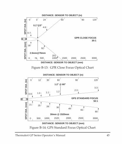
The optical charts indicate the nominal target spot diameter at any given dis-tance from the sensing head. Information in the top half of each diagram isin inches or feet, the bottom half is in metric units. All optical diagramswithin this manual assume 90% energy. Figure B-12 is for the GPR StandardFocus model, Figure B-13 is for the GPR Close Focus model, Figure B-14 isfor the GPS Standard Focus model, and Figure B-15 is for the GPS CloseFocus model.
Thermalert GP Series Operator’s Manual 45
SP
OT
DIA
. (in
)S
PO
T D
IA. (
mm
)
24 60 90 120
30002500200015005000
0
DISTANCE: SENSOR TO OBJECT (mm)
DISTANCE: SENSOR TO OBJECT (in)
92
0.7
18
3
76
4.6
1000201
0.1"@3"
2.5mm@76mm
GPR CLOSE FOCUS30:1
Figure B-13: GPR Close Focus Optical Chart
SP
OT
DIA
. (in
)S
PO
T D
IA. (
mm
)
30 60 90 120
300025001520 200010000
0
DISTANCE: SENSOR TO OBJECT (mm)
DISTANCE: SENSOR TO OBJECT (in)
1.0
28
0.9
21
12
500
1.1 1.2
1.2" @ 60"
2.33.3
254930
30mm @ 1520mm
6580
GPS STANDARD FOCUS50:1
Figure B-14: GPS Standard Focus Optical Chart

46 Thermalert GP Series Operator’s Manual
SP
OT
DIA
. (in
)S
PO
T D
IA. (
mm
)
24 60 90 120
30002500200015005000
0
DISTANCE: SENSOR TO OBJECT (mm)
DISTANCE: SENSOR TO OBJECT (in)
42
0.7
18
8
200
2
1000
100
0.18"@8"
4.5mm@200mm
GPS CLOSE FOCUS45:1
Figure B-15: GPS Close Focus Optical Chart
B.5.8.2 Thermal
Temperature range: -18 to 538°C (0 to 1000°F)
Spectral Response: 8 to 14 microns
Accuracy: ± 1% of reading or ± 1°C (2°F), whichever is(with GP monitor) greater, @ 23°C ± 5°C (73 ± 9°F) ambient
Repeatability: ±0.5% of reading or ± 1°C (2°F), whichever isgreater, @ 23°C ± 5°C (73 ± 9°F) ambient
Response Time: 300 ms (95% response, 4/20mA output)
Temperature Coefficient: 0.15°C per °C (0.15°F per °F)

Thermalert GP Series Operator’s Manual 47
B.5.8.3 Physical
Dimensions: (Refer to Figures B-1 and B-2)
Weight: GPR 275 grams (0.6 lbs), GPS 290 grams (0.65 lbs)
Environmental Rating: NEMA-4 (IEC 529, IP 65) rated with conduit adapterand compression fitting (which prevents liquid fromentering through the connector)
Ambient Operating GPR head: 0 to 65°C (32 to 150°F)Temperature Range: GPS head: 0 to 65°C (32 to 150°F)
with air cooling: 0 to 120°C (32 to 250°F)with water cooling: 0 to 177°C (32 to 350°F)
Note: GPS head laser functions only up to 50°C (120°F) and automatically shutsdown when that temperature is exceeded.
Storage Temperature: -30 to 65°C (-22 to 150°F)
Relative Humidity: 10-95%, non-condensing
Vibration: MIL-STD-810D (IEC 68-2-6): 3G’s, 11 to 200Hz, anyaxis
Mechanical Shock: MIL-STD-810D (IEC 68-2-27): 50G’s, 11msec duration,any axis
48 Thermalert GP Series Operator’s Manual
B.5.9 GPR and GPS Accessories
A full range of accessories for various applications and industrial environ-ments are available. Accessories include items that may be ordered at anytime and added on-site. These include the following:
• Right angle mirror• Sighting viewer (GPR only)• Air purge collar• Conduit adapter• Pipe adapter• Adjustable bracket• Fixed bracket (supplied with the unit)• Mounting nut (supplied with the unit)• Cable: 4m (13ft)• 8m (26ft) high temperature cable• 15m (49ft) high temperature cable• DC activated/isolated Solid State Relay for DC voltages with minimum
0-100V/10A rating• DC activated/isolated SSR for AC voltages with minimum 24-
240VAC/8A rating
B.5.10 Options
A full range of options for various applications and industrial environmentsare available. Options are those items that are factory installed and must beordered with base model units. These include the following:
• NIST certification• Air/water-cooled housing

Thermalert GP Series Operator’s Manual 49
B.6 GP MINIATURE HEAD INFORMATION
The GPM has models available with 2:1 and 10:1 optical resolution. Use thefollowing measurements when determining space requirements for installa-tion.
B.6.1 GPM Head
The sensor can be mounted using the fixed or adjustable mounting bracketaccessory or with a customer-supplied bracket or pipe adapter. (Other acces-sories and options are listed at the end of this section.)
17 (.67)
28 (1.1)
M 12x1
φ 1
4 (.
55)
11 (.43)
mm (in) preinstalled cable
standard cable length 1 m ( 3 ft.)φ 5 (.2)
Figure B-16: The GPM Sensing Head
16 (.63)
20(.8)
27(1.05)
2 (.08)
31 (1.2)
22(.75)
90
14(.51)
45
3.4 (.13)3.4 (.13)
13 (.5)
mm (inches)
Figure B-17: Fixed Mounting Bracket
50 Thermalert GP Series Operator’s Manual
B.6.2 Adjustable Mounting Bracket
If you need more more than one measuring position for the sensing head,use the adjustable mounting bracket accessory.
B.6.3 GPM Head with Air Cooling System
The air cooling option allows the sensor to be used in ambient temperaturesup to 200°C (392°F). The T-fitting allows the air cooling hose to be installedwithout interupting the connections to the electronics. The air-cooling jacketmay be combined with the air purging jacket (Section B.6.4) or with the rightangle mirror (Section B.6.5).
Figure B-18: Adjustable Mounting Bracket Accessory
22 (.75)14
(.51)
3 (.
12)
3(.12)
22(.75)
2(.08)
13 (
.5)
22 (.75)
27 (1.05)
27(1.05)
38(1.5)
mm (inches)
Ambient temperature up to 200°C
Ambient temperature max. 50°C
To terminals
T-FittingHose
Air cooling (max. 35°C)
Sensing headCable
Air hose
Figure B-19: Air Cooling System
Thermalert GP Series Operator’s Manual 51
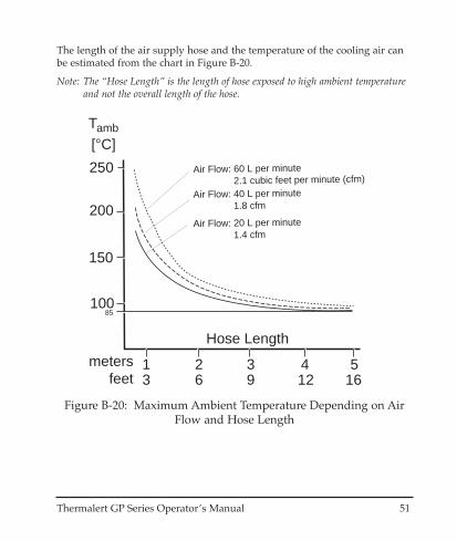
The length of the air supply hose and the temperature of the cooling air canbe estimated from the chart in Figure B-20.
Note: The “Hose Length” is the length of hose exposed to high ambient temperatureand not the overall length of the hose.
2.1 cubic feet per minute (cfm)Air Flow: 60 L per minute
1.8 cfmAir Flow: 40 L per minute
1.4 cfmAir Flow: 20 L per minute
163
100
200
Tamb
[°C]
Hose Length
250
150
85
6 9 12 51 2 3 4meters
feet
Figure B-20: Maximum Ambient Temperature Depending on AirFlow and Hose Length
52 Thermalert GP Series Operator’s Manual
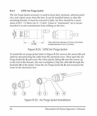
B.6.4 GPM Air Purge Jacket
The Air Purge Jacket accessory is used to keep dust, moisture, airborne parti-cles, and vapors away from the lens. It can be installed before or after themounting bracket. It must be screwed in fully. Air flow should be a maxi-mum of (0.5 - 1.5 liters/sec (1 - 3 cfm). Clean or “instrument” air is recom-mended to avoid contaminants from settling on the lens.
To install the air purge jacket (refer to Figure B-22), remove the sensor (1) andcable by disconnecting the cable from the electronics box. Then open the AirPurge Jacket (3, 4) and screw the white plastic fitting (2) onto the sensor upto the end of the threads. (Do not overtighten.) Slip the cable (6) through thebackside (4) of the jacket. Close the Air Purge Jacket (3, 4) and reconnect thewires to the electronics box.
47(1.85)
φ21
(φ.8
3)
M12
x1
Hose with inner diameter of 3 mm (.12 inches),outside diameter 5 mm (.2 inches)
Figure B-21: GPM Air Purge Jacket
123 45 6
Figure B-22: Air Purge Jacket Installation
Thermalert GP Series Operator’s Manual 53
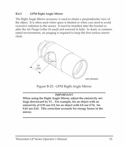
B.6.5 GPM Right Angle Mirror
The Right Angle Mirror accessory is used to obtain a perpendicular view ofthe object. It is often used when space is limited or when you need to avoidexcessive radiation to the sensor. It must be installed after the bracket orafter the Air Purge Collar (if used) and screwed in fully. In dusty or contami-nated environments, air purging is required to keep the first surface mirrorclean.
IMPORTANTWhen using the Right Angle Mirror, adjust the emissivity set-tings downward by 5%. For example, for an object with anemissivity of 0.95 use 0.9; for an object with 0.8 use 0.76; for0.65 use 0.62. This correction accounts for energy losses in themirror.
13(.51)
mm (inches)
Figure B-23: GPM Right Angle Mirror
54 Thermalert GP Series Operator’s Manual
B.6.6 GPM Head Specifications
The following sections contain optical, thermal, and physical specificationsfor the GPM.
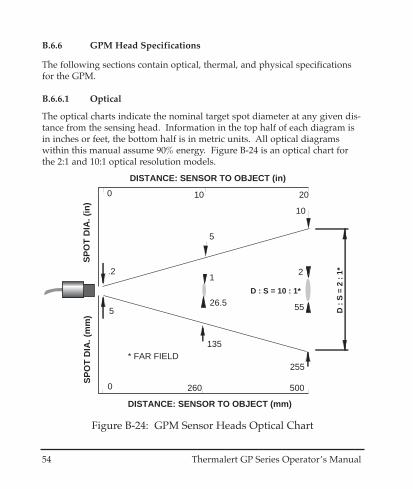
B.6.6.1 Optical
The optical charts indicate the nominal target spot diameter at any given dis-tance from the sensing head. Information in the top half of each diagram isin inches or feet, the bottom half is in metric units. All optical diagramswithin this manual assume 90% energy. Figure B-24 is an optical chart forthe 2:1 and 10:1 optical resolution models.
D :
S =
2 :
1*
260 500
135
255
DISTANCE: SENSOR TO OBJECT (mm)
10
SP
OT
DIA
. (m
m) 5
0
* FAR FIELD
DISTANCE: SENSOR TO OBJECT (in)
SP
OT
DIA
. (in
)
.2
10 200
5
D : S = 10 : 1*
55
2
26.5
1
Figure B-24: GPM Sensor Heads Optical Chart
Thermalert GP Series Operator’s Manual 55
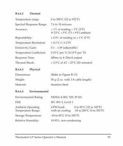
B.6.6.2 Thermal
Temperature range: 0 to 500°C (32 to 932°F)
Spectral Response Range: 7.6 to 18 microns
Accuracy: ± 1% of reading ± 1°C (2°F)@ 23°C ± 5°C (73 ± 9°F) ambient
Repeatability: ± 0.5% of reading or ± 1°C (2°F)
Temperature Resolution: ± 0.1°C (± 0.2°F)
Emissivity/Gain: 0.1 – 1.09 (adjustable)
Temperature Coefficient: 0.15°C per °C (0.15°F per °F)
Response Time: 400ms to 4/20mA output
Thermal Shock: ± 3.5°C at ∆T = 25°C (20 minutes)
B.6.6.3 Physical
Dimensions: (Refer to Figure B-13)
Weight: 50 g (2 oz. with 3 ft cable length)
Material: Stainless Steel
B.6.6.4 Environmental
Environmental Rating: NEMA-4 (IEC 529, IP 65)
EMI IEC 801-3, Level 1
Ambient Operating GPM head: 0 to 85°C (32 to 185°F)Temperature Range: with air cooling: -18 to 200°C (0 to 392°F)
Storage Temperature: -18 to 85°C (0 to 185°F)
Relative Humidity: 10-95%, non-condensing

56 Thermalert GP Series Operator’s Manual
B.6.7 GP Miniature Head Accessories
A full range of accessories for various applications and industrial environ-ments are available. Accessories include items that may be ordered at anytime and added on-site. These include the following:
• Fixed Bracket• Adjustable Bracket• Air Purge Jacket• Right Angle Mirror• T-fitting, Hose, and Air Cooling Jacket
B.6.8 Options
A full range of options for various applications and industrial environmentsare available. Options are those items that are factory installed and must beordered with base model units. These include the following:
• Longer cables–3 m (10 ft), 8 m (26 ft), and 15 m (50 ft)• NIST Certification
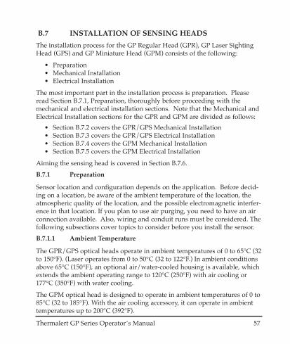
B.7 INSTALLATION OF SENSING HEADS
The installation process for the GP Regular Head (GPR), GP Laser SightingHead (GPS) and GP Miniature Head (GPM) consists of the following:
• Preparation• Mechanical Installation• Electrical Installation
The most important part in the installation process is preparation. Pleaseread Section B.7.1, Preparation, thoroughly before proceeding with themechanical and electrical installation sections. Note that the Mechanical andElectrical Installation sections for the GPR and GPM are divided as follows:
• Section B.7.2 covers the GPR/GPS Mechanical Installation• Section B.7.3 covers the GPR/GPS Electrical Installation• Section B.7.4 covers the GPM Mechanical Installation• Section B.7.5 covers the GPM Electrical Installation
Aiming the sensing head is covered in Section B.7.6.
B.7.1 Preparation
Sensor location and configuration depends on the application. Before decid-ing on a location, be aware of the ambient temperature of the location, theatmospheric quality of the location, and the possible electromagnetic interfer-ence in that location. If you plan to use air purging, you need to have an airconnection available. Also, wiring and conduit runs must be considered. Thefollowing subsections cover topics to consider before you install the sensor.
B.7.1.1 Ambient Temperature
The GPR/GPS optical heads operate in ambient temperatures of 0 to 65°C (32to 150°F). (Laser operates from 0 to 50°C (32 to 122°F.) In ambient conditionsabove 65°C (150°F), an optional air/water-cooled housing is available, whichextends the ambient operating range to 120°C (250°F) with air cooling or177°C (350°F) with water cooling.
The GPM optical head is designed to operate in ambient temperatures of 0 to85°C (32 to 185°F). With the air cooling accessory, it can operate in ambienttemperatures up to 200°C (392°F).
Thermalert GP Series Operator’s Manual 57
58 Thermalert GP Series Operator’s Manual
The electronics enclosure is designed to operate in ambient temperatures of 0to 50°C (32 to 120°F). Operation of these units outside of specified ambienttemperatures is not recommended, and accuracy cannot be guaranteed.
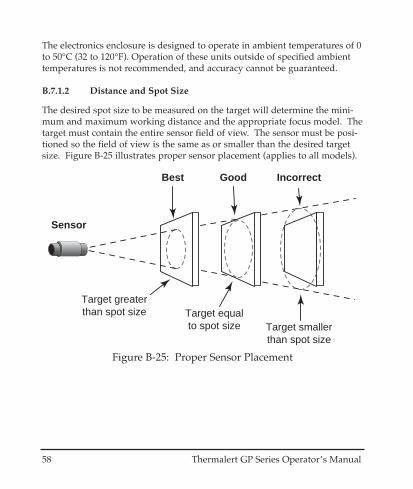
B.7.1.2 Distance and Spot Size
The desired spot size to be measured on the target will determine the mini-mum and maximum working distance and the appropriate focus model. Thetarget must contain the entire sensor field of view. The sensor must be posi-tioned so the field of view is the same as or smaller than the desired targetsize. Figure B-25 illustrates proper sensor placement (applies to all models).
Best Good Incorrect
Target equalto spot size Target smaller
than spot size
Target greaterthan spot size
Sensor
Figure B-25: Proper Sensor Placement
Thermalert GP Series Operator’s Manual 59
B.7.1.3 Atmospheric Quality
It is important to keep the lens clean at all times. A clean lens can preventerroneous readings and possible lens damage. An Air Purge Collar is avail-able, and recommended, for all models to protect the lens from smoke,fumes, dust, and other contaminants.
B.7.1.4 Electrical Interference
To minimize electrical or electromagnetic interference or “noise,” be aware ofthe following:
• Mount the sensor as far away as possible from potential sources of elec-trical interference such as motorized equipment producing large stepload changes.
• With a regular sensing head, use solid or flexible conduit between thehead and electronics box. Check continuity to ensure a good connec-tion of the conduit between the sensor head and electronics box. For agood connection, the ends of the conduit should make metal to metalcontact with the sensor head and the electronics box.
• Use shielded wire for all input and output connections. Connect theshield as described in the sensing head tables in Section B.2.
• Make sure the shield wire in the sensor cable is earth grounded.
• For additional protection, use conduit for the AC power lines and anyexternal connections. Solid conduit is better than flexible conduit inhigh noise environments.
• Do not run AC power for other equipment in the same conduit.
60 Thermalert GP Series Operator’s Manual
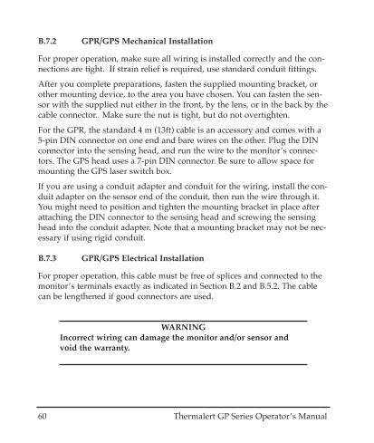
B.7.2 GPR/GPS Mechanical Installation
For proper operation, make sure all wiring is installed correctly and the con-nections are tight. If strain relief is required, use standard conduit fittings.
After you complete preparations, fasten the supplied mounting bracket, orother mounting device, to the area you have chosen. You can fasten the sen-sor with the supplied nut either in the front, by the lens, or in the back by thecable connector. Make sure the nut is tight, but do not overtighten.
For the GPR, the standard 4 m (13ft) cable is an accessory and comes with a5-pin DIN connector on one end and bare wires on the other. Plug the DINconnector into the sensing head, and run the wire to the monitor’s connec-tors. The GPS head uses a 7-pin DIN connector. Be sure to allow space formounting the GPS laser switch box.
If you are using a conduit adapter and conduit for the wiring, install the con-duit adapter on the sensor end of the conduit, then run the wire through it.You might need to position and tighten the mounting bracket in place afterattaching the DIN connector to the sensing head and screwing the sensinghead into the conduit adapter. Note that a mounting bracket may not be nec-essary if using rigid conduit.
B.7.3 GPR/GPS Electrical Installation
For proper operation, this cable must be free of splices and connected to themonitor’s terminals exactly as indicated in Section B.2 and B.5.2. The cablecan be lengthened if good connectors are used.
WARNINGIncorrect wiring can damage the monitor and/or sensor andvoid the warranty.

Thermalert GP Series Operator’s Manual 61
B.7.4 GPM Mechanical Installation
For proper operation, make sure all wiring is installed correctly and the con-nections are tight.
After you complete preparations, fasten the supplied mounting bracket, orother mounting device, to the area you have chosen. Fasten the sensor to thebracket with the supplied nut. Make sure the nut is tight, but do not over-tighten.
The sensor comes with a 1 m (3ft) cable attached to it and bare wires on theother end. Once you have the sensor mounted, run the cable to the monitor’sterminals.
B.7.5 GPM Electrical Installation
For proper operation, this cable must be free of splices and connected exactlyas indicated in Section B.2. For mounting sensor cable in a conduit, use theT-fitter and hose accessory with the sensor head.
For proper operation, this cable must be free of splices and connected to themonitor’s terminals exactly as indicated in Section B.2. This cable cannot belengthened, but it can be shortened.
WARNINGIncorrect wiring can damage the monitor and/or sensor andvoid the warranty.

62 Thermalert GP Series Operator’s Manual
B.7.6 Aiming the Sensing Head
All sensing heads that can be attached to the GP monitor are aimed using thesame technique, which is to peak the sensor to its maximum signal. (The GPShas laser aiming.) To do this, all connections must be secure and powerapplied to the monitor. If a temperature does not display, press the but-ton until it does. (Refer to Section 2.4 for operating instruction.)
To aim the sensor, complete the following:
1. Slightly loosen the mounting bracket’s nuts. 2. Point the sensor toward the target. 3. Move it around until the target’s temperature displays on the monitor. 4. Secure the mounting bracket.
Thermalert GP Series Operator’s Manual 63
B.7.7 Cleaning the Sensing Head Lens
Keep the lens clean at all times. Any foreign matter on the lens will affectmeasurement accuracy. However, care should be taken when cleaning thelens. To clean the lens, do the following:
1. Lightly blow off loose particles.2. Gently brush off remaining particles with a soft camel hair brush.3. Clean remaining “dirt” using a cotton swab dampened in distilled water.
Do not scratch the surface.
For finger prints or other grease, use any of the following:
• Denatured alcohol• Ethanol• Kodak® lens cleaner
Apply one of the above to the lens. Wipe gently with a soft, clean cloth untilyou see colors on the surface, then allow to air dry. Do not wipe the surfacedry, this may scratch the surface.
If silicones (used in hand creams) get on the lens, gently wipe the surfacewith Hexane. Allow to air dry.
WARNINGDo not use ammonia or cleaners with ammonia on the lens, thismay result in permanent damage to the lens’ surface.

64 Thermalert GP Series Operator’s Manual

Thermalert GP Series Operator’s Manual 65
APPENDIX C EMISSIVITY
The emissivity of a measured object is determined by the material it consistsof. Emissivity is a measure of an object’s ability to absorb, transmit, and emitinfrared energy. It can have a value from 0 (shiny mirror) to 1.0 (blackbody).
C.1 HOW TO DETERMINE EMISSIVITY
Section C.2 lists common emissivity values for metals, and Section C.3 listscommon emissivity values for non-metals. If your object is not similar to anythe materials given, or extra precision is desired, you can use one of the fol-lowing methods for determining a specific emissivity value.
1. If an accurate target temperature can be established using a contact tem-perature probe, you may adjust the emissivity/gain setting until the IRtemperature reading agrees with the contact device reading.
2. Cover a portion of the target’s surface with masking tape or flat blackpaint. The emissivity of both is 0.95. Allow time for the masking tape´stemperature to equalize with the temperature of the surface underneath.Measure the masked area, using an emissivity/gain setting of 0.95, andthen immediately measure the unmasked area. If the two temperatures aremuch different, emmissivity may affect your readings. Compensate byadjusting emissivity while reading the unmasked area until it agrees withthe 0.95 reading of the masked area. This value should then be usedwhenever that object or material is to be measured in the future.
66 Thermalert GP Series Operator’s Manual
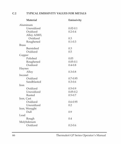
C.2 TYPICAL EMISSIVITY VALUES FOR METALS
Material Emissivity
AluminumUnoxidized 0.02-0.1Oxidized 0.2-0.4Alloy A3003,
Oxidized 0.3Roughened 0.1-0.3
BrassBurnished 0.3Oxidized 0.5
CopperPolished 0.03Roughened 0.05-0.1Oxidized 0.4-0.8
HaynesAlloy 0.3-0.8
InconelOxidized 0.7-0.95Sandblasted 0.3-0.6
IronOxidized 0.5-0.9Unoxidized 0.05-0.2Rusted 0.5-0.7
Iron, CastOxidized 0.6-0.95Unoxidized 0.2
Iron, WroughtDull 0.9
LeadRough 0.4
MolybdenumOxidized 0.2-0.6

Thermalert GP Series Operator’s Manual 67
Material Emissivity
NickelOxidized 0.2-0.5Electrolytic 0.05-0.15
PlatinumBlack 0.9
SteelCold-Rolled 0.7-0.9Ground Sheet 0.4-0.6Polished Sheet 0.1Oxidized 0.7-0.9Stainless 0.1-0.8
TitaniumOxidized 0.5-0.6

68 Thermalert GP Series Operator’s Manual
C.3 TYPICAL EMISSIVITY VALUES FOR NON-METALS
Material Emissivity
Asbestos 0.95Asphalt 0.95Basalt 0.7
CarbonUnoxidized 0.8-0.9Graphite 0.7-0.8Carborundum 0.9Ceramic 0.95Clay 0.95Concrete 0.95Cloth 0.95
GlassPlate 0.85Gravel 0.95Gypsum 0.8-0.95Ice 0.98Limestone 0.98Paint (non-al.) 0.9-0.95Paper (any color) 0.95Plastic (opaque, over 20 mils) 0.95Rubber 0.95Sand 0.9Snow 0.9Soil 0.9-0.98Water 0.93Wood, Natural 0.9-0.95
Thermalert GP Series Operator’s Manual 69
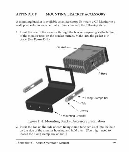
APPENDIX D MOUNTING BRACKET ACCESSORY
A mounting bracket is available as an accessory. To mount a GP Monitor to awall, post, column, or other flat surface, complete the following steps:
1. Insert the rear of the monitor through the bracket’s opening so the bottomof the monitor rests on the bracket surface. Make sure the gasket is inplace. (See Figure D-1.)
Gasket
Fixing Clamps (2)
Tab
Mounting Bracket
Screws
Hole
Figure D-1: Mounting Bracket Accessory Installation
2. Insert the Tab on the side of each fixing clamp (one per side) into the holeon the side of the monitor housing and hold them. (You might need toloosen the fixing clamp screws first.)

70 Thermalert GP Series Operator’s Manual
3. Tighten the fixing clamp screws on each fixing clamp. Make sure the tabsare snug against the bracket frame (Figure D-2). Do not overtighten.
Tighten FixingClamp Screws
Before mounting bracket,connect wires and attach rear cover
Figure D-2: Completing the Installation
4. You will need to attach wires to the monitor’s terminals and attach therear cover before mounting the bracket onto a surface. (Refer to the manu-al for wiring instructions for your particular device.
5. Use 3 appropriately sized screws or bolts to fasten the bracket onto yourwork surface.
This completes the monitor bracket accessory installation.
Thermalert GP Series Operator’s Manual 71
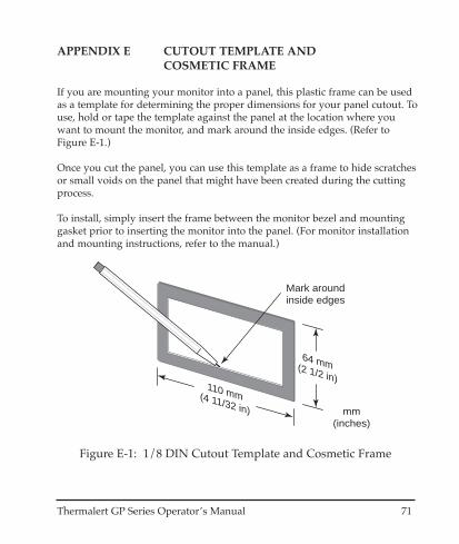
APPENDIX E CUTOUT TEMPLATE AND COSMETIC FRAME
If you are mounting your monitor into a panel, this plastic frame can be usedas a template for determining the proper dimensions for your panel cutout. Touse, hold or tape the template against the panel at the location where youwant to mount the monitor, and mark around the inside edges. (Refer toFigure E-1.)
Once you cut the panel, you can use this template as a frame to hide scratchesor small voids on the panel that might have been created during the cuttingprocess.
To install, simply insert the frame between the monitor bezel and mountinggasket prior to inserting the monitor into the panel. (For monitor installationand mounting instructions, refer to the manual.)
110 mm(4 11/32 in)
64 mm(2 1/2 in)
mm(inches)
Mark around inside edges
Figure E-1: 1/8 DIN Cutout Template and Cosmetic Frame

72 Thermalert GP Series Operator’s Manual

Thermalert GP Series Operator’s Manual 73
APPENDIX F TRACEABILITY OF INSTRUMENT CALIBRATION
The temperature sources (blackbodies) used to calibrate this instrument aretraceable to the U.S. National Institute of Standards and Technology (NIST).(Refer to Figure F-1.)
The NIST certificate describes the equipment used for calibration and anycorresponding NIST report numbers. In addition, the certificate lists testaccuracy data and the next calibration date.
NIST certificates are available as an option (must be ordered with the instru-ment). Contact the manufacturer (not NIST) to order this option.
National Institute of Standards and Technology(NIST)
NIST Certified Calibration Lab: calibration in accordance with MIL-STD-45662 and against
standards traceable to NIST
High Temperature1200 - 3000°C (2200 - 5400°F) Certified Radiation Transfer
Standard
Medium Temperature200 - 1200°C (400 - 2200°F)
Certified ThermocoupleInstrumentation & NIST
Calibrated Radiation TransferStandard Instrument
Low Temperature-18 - 870°C (0 - 1600°F)
Certified RTDInstrumentation
Calibration Source(Blackbody)
Emissivity 1.0
Calibration Source(Blackbody)
Emissivity < 1
MeasuredSource
Emissivity
Calibrated Product
Manufacturer
Figure F-1: NIST Traceability

74 Thermalert GP Series Operator’s Manual

Thermalert GP Series Operator’s Manual 75
APPENDIX G CE CONFORMITY FOR THE EUROPEAN COMMUNITY
This instrument conforms to the following standards:
• EN50081-1 Emission Standard• EN50082-1 Immunity Standard

76 Thermalert GP Series Operator’s Manual