
Rapid Mars Transits With Exhaust- Modulated Plasma Propulsion · PDF fileNASA Technical Paper...
18
NASA Technical Paper 3539 Rapid Mars Transits With Exhaust- Modulated Plasma Propulsion Franklin R. Chang-Diaz Michael M. Hsu Ellen Braden Ivan Johnson Tien Fang Yang (MASA-TP-3539) RAPID MARS TRANSITS _ITH _XHAUST-MoDULAT60 PLASMA PKCPUL_IQN (NASA. Johnson Space Center) 15 _) N96-19285 Uric|as HI/20 0101125 March 1995 https://ntrs.nasa.gov/search.jsp?R=19960014624 2018-05-03T00:59:35+00:00Z
-
Upload
hoangnguyet -
Category
Documents
-
view
215 -
download
0
Transcript of Rapid Mars Transits With Exhaust- Modulated Plasma Propulsion · PDF fileNASA Technical Paper...

NASA Technical Paper 3539
Rapid Mars Transits With Exhaust-
Modulated Plasma Propulsion
Franklin R. Chang-DiazMichael M. Hsu
Ellen Braden
Ivan Johnson
Tien Fang Yang
(MASA-TP-3539) RAPID MARS TRANSITS
_ITH _XHAUST-MoDULAT60 PLASMA
PKCPUL_IQN (NASA. Johnson Space
Center) 15 _)
N96-19285
Uric|as
HI/20 0101125
March 1995
https://ntrs.nasa.gov/search.jsp?R=19960014624 2018-05-03T00:59:35+00:00Z

NASA Technical Paper 3539
Rapid Mars Transits With Exhaust-
Modulated Plasma Propulsion
Franklin R. Chang-Diaz, Ellen Braden, and Ivan Johnson
Lyndon B. Johnson Space Center
Houston, Texas
Michael M. Hsu
United States Navy
det. Department of Physics
Cambridge University, U.K.
Tlen Fang Yang
Yang Technologies, Inc.
Cambridge, Massachusetts
March 1995

Thispublicationis availablefrom theNASA CenterforAerospaceInformation,800ElkridgeLandingRoad,LinthicumHeights,MD 21090-2934,(301)621-0390
Section
1
2
3
4
5
6
7
8
9
10
Contents
Page
Abstract .................................................................................................................................... 1
Introduction .............................................................................................................................. 1
Operational Modes ................................................................................................................... 1
System Description .................................................................................................................. 1
Mission Concept ....................................................................................................................... 2
Mission Analysis ...................................................................................................................... 3
Performance ............................................................................................................................. 5
Abort Scenarios ........................................................................................................................ 8
Extended-Stay Missions ........................................................................................................... 9
Conclusion ................................................................................................................................ 9
References ................................................................................................................................ 9
iii

Figure
1
2
Table
I
Figures
Schematic representation of the variable Isp (or exhaust-modulated plasma rocket) ..............
Theoretical rocket performance envelope for hydrogen propellant at
10 MWe and 60% efficiency ....................................................................................................
3 Typical one-way 90-day Mars transit with exhaust modulation ..............................................
4 Trajectory plot for a 90-day transit showing the thrust acceleration vectorsat 10 intervals during the mission ............................................................................................
5 Isp profile over the entire transit ..............................................................................................
6 Total fuel expenditure ...............................................................................................................
7 The eccentricity of Mars' orbit ................................................................................................
8 Typical trajectory plot for a high payload, longer duration transit ...........................................
9 A total mission with nearly symmetric inbound and outbound legs ........................................
10 Typical powered abort returning the spacecraft to Earth 75 days after abort conditionis declared .................................................................................................................................
11 Typical 180-day abort trajectory ..............................................................................................
12 Complete extended-duration mission with symmetric inbound and outbound legs ................
Tables
General System Parameters ......................................................................................................
Page
2
8
8
8
Page
2
iv
Abstract
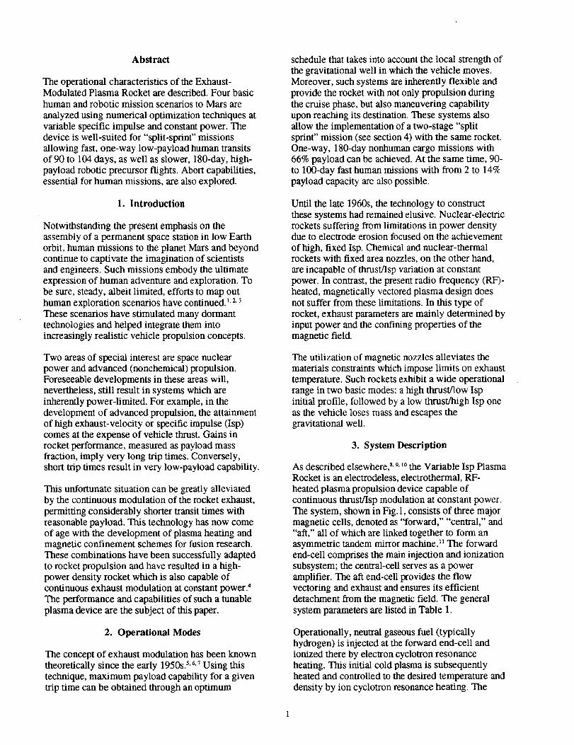
The operational characteristics of the Exhaust-Modulated Plasma Rocket are described. Four basichuman and robotic mission scenarios to Mars are
analyzed using numerical optimization techniques atvariable specific impulse and constant power. Thedevice is well-suited for "split-sprint" missionsallowing fast, one-way low-payload human transitsof 90 to 104 days, as well as slower, 180-day, high-payload robotic precursor flights. Abort capabilities,essential for human missions, are also explored.
1. Introduction
Notwithstanding the present emphasis on theassembly of a permanent space station in low Earthorbit, human missions to the planet Mars and beyondcontinue to captivate the imagination of scientistsand engineers. Such missions embody the ultimateexpression of human adventure and exploration. Tobe sure, steady, albeit limited, efforts to map outhuman exploration scenarios have continued. 1,2,3These scenarios have stimulated many dormanttechnologies and helped integrate them intoincreasingly realistic vehicle propulsion concepts.
Two areas of special interest are space nuclearpower and advanced (nonchemical) propulsion.Foreseeable developments in these areas will,nevertheless, still result in systems which areinherently power-limited. For example, in thedevelopment of advanced propulsion, the attainmentof high exhaust-velocity or specific impulse (Isp)comes at the expense of vehicle thrust. Gains inrocket performance, measured as payload massfraction, imply very long trip times. Conversely,short trip times result in very low-payload capability.
This unfortunate situation can be greatly alleviatedby the continuous modulation of the rocket exhaust,permitting considerably shorter transit times withreasonable payload. This technology has now comeof age with the development of plasma heating andmagnetic cordinement schemes for fusion research.These combinations have been successfully adaptedto rocket propulsion and have resulted in a high-power density rocket which is also capable ofcontinuous exhaust modulation at constant power?The performance and capabilities of such a tunableplasma device are the subject of this paper.
2. Operational Modes
The concept of exhaust modulation has been knowntheoretically since the early 1950s. 5,6.7 Using thistechnique, maximum payload capability for a giventrip time can be obtained through an optimum
schedule that takes into account the local strength ofthe gravitational well in which the vehicle moves.Moreover, such systems are inherently flexible andprovide the rocket with not only propulsion duringthe cruise phase, but also maneuvering capabilityupon reaching its destination. These systems alsoallow the implementation of a two-stage "splitsprint" mission (see section 4) with the same rocket.One-way, 180-day nonhuman cargo missions with66% payload can be achieved. At the same time, 90-to 100-day fast human missions with from 2 to 14%payload capacity are also possible.
Until the late 1960s, the technology to constructthese systems had remained elusive. Nuclear-electricrockets suffering from limitations in power densitydue to electrode erosion focused on the achievement
of high, fixed Isp. Chemical and nuclear-thermalrockets with fixed area nozzles, on the other hand,
are incapable of thrust/Isp variation at constantpower. In contrast, the present radio frequency (RF)-heated, magnetically vectored plasma design doesnot suffer from these limitations. In this type ofrocket, exhaust parameters are mainly determined byinput power and the confining properties of themagnetic field.
The utilization of magnetic nozzles alleviates thematerials constraints which impose limits on exhausttemperature. Such rockets exhibit a wide operationalrange in two basic modes: a high thrust/low Ispinitial profile, followed by a low thrust/lligh Isp oneas the vehicle loses mass and escapes thegravitational well.
3. System Description
As described elsewhere, 8'9.10the Variable Isp PlasmaRocket is an electrodeless, electrothermal, RF-heated plasma propulsion device capable ofcontinuous thrustflsp modulation at constant power.The system, shown in Fig. 1, consists of three majormagnetic cells, denoted as "forward," "central," and"aft," all of which are linked together to form anasymmetric tandem mirror machine) 1The forwardend-cell comprises the main injection and ionizationsubsystem; the central-cell serves as a poweramplifier. The aft end-cell provides the flowvectoring and exhaust and ensures its efficientdetachment from the magnetic field. The general
system parameters are listed in Table 1.
Operationally, neutral gaseous fuel (typicallyhydrogen) is injected at the forward end-cell andionized there by electron cyclotron resonanceheating. This initial cold plasma is subsequentlyheated and controlled to the desired temperature anddensity by ion cyclotron resonance heating. The

IFigure 1. Schematic representation of the variable
latter process occurs in the much larger central-cell
of the device. After heating, the plasma enters atwo-stage hybrid nozzle at the aft end-cell where it is
exhausted to provide modulated thrust.
Table 1. General System Parameters
Variable frequency
Four double half loop
antennae in central-cell
Two double half loop
antennae in end-cells
Transmitter operating
voltage
Central-cell magnetic field
End-cell magnetic field
Mirror field
Mirror ratio
Superconductor
500 kHz to 10 Mhz
2 MW - each
1 MW- each
10 - 30 KV
0.24T
0.6 T
1.2T
2.0
NbTi or
high temp. S.C.
The basic superconducting tandem mirror geometryhas been modified to exploit the inherent axial
lsp (or exhaust-modulated) plasma rocket.
asymmetry of these devices in order to provide apreferred flow direction. This approach is used to
guide, control, and radially confine the plasma frominjection to exhaust. The tandem mirror also ensures
magnetohydrodynamic stable operation over a widerange of plasma temperatures and densities.
Additionally, the mirror enables exhaust Isp andflow-rate control through manipulation of the end-
cells as both input and output controlling gates.
Experimental and theoretical investigations of this
propulsion concept have been carried out overseveral years. 12,13._4Based on these results, a 10MW
nuclear electric system operating at 68% efficiencyhas been considered. In terms of specific power or"'Alpha," a value of 6 Kg/KW has been assessed. 15
This value, although somewhat optimistic, reflects
brisk progress in nuclear electric technology, as wellas the high-voltage (low current) characteristic of
RF-heated propulsion. The expected rocket
performance parameters are shown in Fig. 2.
4. Mission Concept
The mission approach considered here is the familiar"split-sprint" scenario envisioned in numerous
previous studies. A one-way, slow, high-payloadcapacity, automated cargo ship leaves first and
places a habitat, fuel, and supplies on Mars. Some of
the infrastlucture will be located at strategic points
on orbit and on the planet's surface (an operatingnuclear power plant on the surface, fuel and
redundant landers on Mars orbit). Additionally, a
fuel supply will be located on orbit at the edge of theEarth's gravitational sphere of influence.

103 . 104
2
101 - 102
2.-
i I I I I i
_,', P = 10 MW, Hydrogen
\\
./" \"x
I / { I I ""I5 10 15 20 25
(Is_'lO_](sec)
1lO4
4
I-4
10_
1021 _"
-4
102 '_ 1020
30
Figure 2. Theoretical rocket performance envelope forhydrogen propellant at 10 MWe and 60% efficiency.
Following completion of this robotic mission, asmaller, low-payload, fast ship will carry the crew to
Mars. The ship will pick up its final fuel load for
Mars at a staging rendezvous point at the edge of theEarth's sphere of influence. Failure to do so willabort the mission back to Earth. The fast cruise to
Mars will be under modulated exhaust at maximum
power on a trajectory designed for Mars-orbit
insertion. Rendezvous with supplies and lander at
Mars will be required to effect a landing.
An important feature of a human mission should be
its abort capability. Failure of a major system whileen route could require return to Earth or, in some
cases, use of the destination planet as a "safe haven."Such abort capability was inherent (and used) in
project Apollo and exists today in all Space Shuttlemissions. Accordingly, interplanetary human
missions should also possess such capability.
Finally, as shown in section 6, the relative motion of
Earth and Mars poses an interesting challenge to themission designer. Very fast human opposition-class
(opposition is defined here as the opposite alignmentof the Sun and Mars with respect to an observer
situated on Earth) missions are possible with exhaust
modulation; however, a symmetric return leg cannot
be accomplished in the same Martian year for transittimes of less than 104 days. Symmetric outbound
and inbound missions of 90 days (and possibly less)
one-way are possible if the crew "winters down" on
Mars for a period of 2 earth years.
Such scenarios, while far too ambitious for the first
mission, are not implausible for future expeditionsbuilding up to a permanent outpost on the planet.The use of Martian raw materials and installation of
abundant surface nuclear power will more thanenable these long stays.
5. Mission Analysis
The power-limited equations for the interplanetary
vehicle will be described here briefly. More detaileddescriptions are provided by Irving and Melbourne.16
The thrust, "T," the power in the thrust beam, "p,"the specific mass of the power plant, "ct," and the
thrust acceleration, "a r," for power-limited systemsare written,
T=thp.c
1
p = .rhp c 2
m w
P
m
p=__PE
where rhp is the propellant flow rate and c is theexhaust velocity. This quantity is related to thespecific impulse "Isp" through the familiar relation:
c = g.Isp, where g is the acceleration of gravity atthe Earth's surface, 9.8 m/seC. The remaining
quantities are the total spacecraft mass, "m," the
power plant mass, "row," and its power rating, "P."
(1)
A rocket equation for power-limited propulsion
systems can be written from the above equations by
solving for "(at) 2'' and then integrating over time asfollows:
1 1 _ 0t a_. dt (2)m( t ) m o 2 . m W . e J,o
where "m(t)" is the spacecraft mass at time, "t," "mo"is the initial spacecraft mass, and "e" is the powerplant efficiency.
The vehicle parameters can be separated from the
trajectory parameters and the rocket equation can berewritten as:
1 1 1= __ +--. p(t) 2
re(t) m o rnw
where
!
ft)2 = 2 . e ar2.dtto
(3)

At the final time, "tr" "13" can be written as,
t/ = m. , where:E
j: = 1 tt, 2
is the performance index.
The trajectory is optimized independently of thevehicle by minimizing f, which effectivelyminimizes the amount of propellant required for themission. This optimized trajectory is then used withthe vehicle parameters, which are determined by themission planner, to calculate the power plant andpayload mass fractions.
The spacecraft mass at any time, "t," is equal to the
sum of the payload mass, "m v the power plant
mass, "row," and the propellant mass, "me(t)."
re(t) = m z + m w+ re(t) (4)
The initial propellant mass, "rap(O), "is assumed tobe exactly the amount of propellant necessary tocomplete the mission, so at the end of the mission,
%(t) = O.
From reference 16, the maximum payload massfraction and the propellant mass fraction can beshown to be,
I
mL[ =(1--15) 2mo m_m_m
(5)
mp(O) =13m o
(6)
where
(7)
Another parameter of interest is the lsp time historyof the optimized transfer. Isp(t) is a function of thethrust acceleration time history, the integral of thethrust acceleration squared, a, e, and J.
Isp (t) -1
g. at(t)
+jar 2. dtto
(8)
To compute the optimal Isp as a function of time, the
optimal control functions "are .... a_ ." "a.." and the• 6_ _ Jy" JE
resulUng value for J need to be found. Thefunctions "a .... a_," and "a_" are found by
Tx' _) lz
solving an optimization problem defined as follows.
The performance function is,
t!
to
(9)
The equations of motion are:
r=v
(10)
where li is the Sun's gravitational parameter, 1.32715 1020m3/sec 2.
The initial conditions are:
7o = _o(to),(11)
Vo = re(t0)
where _,and V_are the position and velocity vectors
of the Earth at the initial time, to. The final
(12)
conditions are:
where _ and V_ are the position and velocity
vectors of Mars at time, tF
From the calculus of variations, as shown in Brysonand HO, 17 the Hamiltonian is defined as
6
H =Z_,i.fi +Li=l
(13)

lwhere L = 2a/from equation (9), '_" are the right-
hand side of equation (I0), and ",;L" are the Lagrangei
multipliers corresponding to equation (I0).
From the first necessary conditions for an extremal,
_,r =-_-I3Y'(_v "?) 1_-_ _,y
(14)
the final time, "tf" and satisfying the terminalconstraints in equation (12).
This constrained minimization problem is solved using
a numerical optimization-method in the programHybrid Optimization Technique (HOT). HOT providesthe interplanetary simulation by integrating equations(10) and (14), numerically using equation (15) for thecontrol values, and using equations (11) and (16) forthe initial state and multiplier conditions, respectively.The initial _,'s are iterated upon using the Davidon-Fletcher-Powell Penalty Function Method, la which alsoresides in HOT.
6. Performance
A representative set of mission scenarios, asdescribed in section 4, was studied using thenumerical techniques outlined above. No attempt hasbeen made in this initial study to account for thegravitational effects of the departure and destinationplanets. Rather, the ships move in heliocentlic spaceonly under the gravity of the Sun. Boundaryconditions require zero relative velocities betweenthe ship and the planet at both the departure andarrival points. Furthermore, these points are chosento coincide with the position of the appriopriateplanet at the departure and arrival times. Optimizedtrajectories accounting for the planets' gravitationalfields and low orbit departure and arrival, as well asassorted techniques for aerobraking and gravityassist will be taken up in a future study.
where,
and
aTx =--_i
aTy =-_,y
aTz =--_,z
(15)
After application of the calculus of variations, theoptimization problem requires minimizing "I 2'' as afunction of the initial values of the Lagrangemultipliers,
Xx(0),_.,(0),Xz(0)
X,(0),Xy(0),X_(0)(16)
Given the launch date and the desired length of the trip,the initial state vector of Earth and the final state vector
of Mars (or vice versa) are calculated. From theseboundary conditions, the optimization programcomputes the value of"J" which, roughly described, isa measure of the fuel necessary to accomplish thegiven mission. From the above formulation, theassumed values of "¢£' and "e" are used to calculate
the value of "[3," the propellant mass fraction of therocket. From "13,"the payload and power plant mass
fractions are also calculated. The trajectory iscomputed considering only the heliocentric sphere ofinfluence, and seeks to match perfectly the initial andfinal state vectors of the planets.
A 90-day trajectory profile from Earth to Mars (Fig.3) will be used to illusllate the performance andproperties of an exhaust-modulated rocket. Thetrajectories are integrated in convenient half-day(43,200 seconds) segments. Vehicle moves inheliocentric space matching the initial and finalpositions and velocities of Earth and Mars, respec-tively. Vehicle starts with zero Earth-relativevelocity and arrives at Mars with zero relativevelocity as well. Techniques to optimize Earthescape and Mars capture are considered separately.

, , _ )
1 ............................. *- +"-=: ;" '" _: :-: _ _ -_...............................
i/ i _Y" ! "'q. !', !
i/ i -":: ::',, i ', i........ ,'-".......... _.-,_-...--_ .......... ,'........... _..+-.+'-.._-----. _.---i ..........
,_ ........!.........._..........i..........._"-- ........P-'.;-!..........
1 .......... .......,....... .................i::',i:........ ..............;+s ......... ; .......... ; .......... _- ! .......... i .......... i .......... _.........i+il....... ]
"2-2 -1+S -1 -&S 0 OS 1 I .$
Figure 3, Typical one-way 90-day Mars transit withexhaust modulation,
The thrust acceleration vectors associated with the
90-day trajectory are shown in Fig. 4, while the Ispas a function of time is plotted in Fig. 5. Inspectionof these graphs shows the greatest velocity changesnear the beginning and the end of the mission. Themidcourse phase of the trajectory is a high Isp, low-thrust "quasicoast" period. The vehicle massvariation as a function of time is shown in Fig. 6. It
indicates the greatest fuel expenditure at thebeginning and at the end of the trajectory.
,-" . "'., . , ,
"?"..............................................'T-!.............................
_, ......................... Pmo+........ Z ............. _........... ,-'r .............
- _ ,
_o,, ".........-+.............]..............::-..........r-'-_.+/+.+--:-.............•. _ _ + ,-,: i "_ !
, . : _._""+-.. _ .,,*" .,,,.__ !.............,....... .............._.............+. i ! I • i ,_ i i
i i i i i
• 1 -o.5 0.5 1 1.5
Figure 4. Trajectory plot for a 90-day transit showing
the thrust acceleration vectors at 10 intervals during
the mission. Thrust acceleration is nearly radial,decreasing in magnitude toward the midpoint of the
mission, reversing direction, and increasing again atMars arrival.
The eccentricity of Mars' orbit (.0934) causes a
considerable variability in the radial distance an
Earth-Mars trajectory must cover. The Earth's orbit,
being much less eccentric (.0167), is less of a factor
when determining optimal trajectories. The greater
the radial distance, the more the rocket must struggleagainst the gravity well of the Sun. Therefore, the
best possible one-way trajectories arrive at Mars, or
are launched from Mars, when the planet itself is
near perihelion. This is shown in Fig. 7.
£I
//
//
I I ISO I_ 30 II
! I
\\
Figure 5. lsp profile over the entire transit. Isp and thrust
are exchanged continuously at constant (maximum) power.The profile isnearly symmetric showing only a minordifference at Mars, due to the combined effects of a lower
Sun's gravity and reduced total mass at arrival
, J I l
m N
Figure 6. Total fuel expenditure. Most of the fuel is
spent during the initial and final high-thrust phases of
the mission. The use of gravity assist and aerobrakingtechniques may further reduce the fuel expenditure atthese two ends.
One can define a phase angle O for the transit as the
angle subtended between two radii originating at theSun and intercepting the departure and arrival points.
Trajectories which traverse small phase angles are
generally fuel-inefficient, as confirmed by experi-
mentation with these approaches. A phase angle ofroughly 60 ° yields the optimum results for a 90-day
mission. Phase angles more or less than the optimum
values, as determined through iterative runs, arefuel-inefficient. Thrust is wasted to counteract
components of the initial velocity which would
improve, rather than hinder, the rocket' s travel timeto Mars.

1 ......... i
o.s ........... i ...........
-1 ...........
•._ -1.s -i _ o o.5 1 1.s 2m
Figure 7. The eccentricity of Mars' orbit provides anoptimum window of opportunity for the transit whenthe planet's orbit is closest to that of Earth.
The Martian year of 686.9 days forces a period ofopposition of the planets approximately once every 2years. In the years 2016 and 2018, the oppositionsare relatively close to the perihelion of Mars. These2 years offer three launching options: two humanand one robotic. For example, the "tugboat" profileshown in Fig. 8 gives little regard to the travel timeof the rocket and seeks to maximize the payloadmass fraction placed in Mars orbit. As described insection 4, such a profile is used to deliver the habitat,return fuel, and supplies to Mars. Once on the planet,in situ resource utilization machinery could be set inmotion. The nuclear power plant on board mightalso be used to provide supplemental power to thehabitat and, hencel become part of the usefulpayload upon arrival.
Once the operation of the equipment is started andverified from the safety of Earth, the human missioncould commence during the next 2-year cycle. Theprofile shown in Fig. 8 is a 180-day mission with a66.66% payload mass traction. However, longermissions with better mass fractions are possible.
The first human mission considered here is a short
one shown in Fig. 9. This profile is executed withinthe same Martian year. The mission encompasses a101-day outbound trip, a 30-day stay, and a 104-dayreturn. This "speedboat" option is one of the shortestMars missions thus far projected, albeit with a 2%payload mass fraction in each direction.
Such short human transits ameliorate the
physiological hazards associated with long humanexposure to the space environment. Moreover, thecontinuous acceleration provides an artificial gravity
of sorts which may have added positive effects.Reduced mission duration (235 days) would putmuch less of a requirement on the development oflong-duration facilities and their associatedmaintenance. Radiation exposure would be reducedas well.
i ! _ i i i ,t* _ ,,,p_
........._'_"---_..........i"":'_4"-_::'"'_.........","................i : ,: : : ,. : ,
°'...../!..........:/-i..........!........... ...........
........".[..........7"_r, ........7........f;:-" ::-/ :_
.........i..........!::-:i"...... ....................!..........i i i i
• -2 .I.s .1 ,os o o.5 1 _.5AId
Figure 8. Typical trajectory plot for a high payload,longer duration transiL Values of 18% payload-massfraction and 90 days are also possible with the sameengine, illustrating the dual nature of this propulsionsystem.
,r_tory
..........i::::.................... ............,_ o-....-.._..........;..........-.........#_._......i...... !-_------_-i..........
! ",, ia,.i.:.. ! ..6-'" ! !
.I .......... ! .......... b-.-M.e_::-::-:-'-:-_'-r.'-L--.-. .......... : ......... : ..........
"2-2 .1.5 -1 -o.s 2u s 1 s
Figure 9. A total mission with nearly symmetricinbound and outbound legs. While shorter transits areallowed by the propulsion system, the planet'saSgnment becomes unfavorable for transits less than100 days. Shorter transits are possible if the missionincludes an extended stay on the surface of the planet.
Reducing the time of stay on Mars in this profiledoes not yield substantial improvements in thetransit times or payload mass fractions. Shorteningthe stay to 20 days might yield a decrease of 6 daysoutbound and 5 days inbound and keep the payloadmass fraction constant.

7. Abort Scenarios
An important attribute of the exhaust-modulatedplasma rocket is its powered abort capability.Should the habitat fail, the crew becomeincapacitated, or one or more of the modules of therocket cluster fail, the system has a limitedcapability to return directly to Earth or abort toMars, albeit with an increased travel time.
The issues associated with powered aborts back to
Earth are the nominal mission profile, the time ofabort, and the abort duration. Given the nominalmission profile and the time at which the decision toabort is implemented, the fuel remaining and theinitial state vector of the spacecraft are determined.The abort duration specifies the location of Earth atthe arrival point and, consequently, the final statevector. The same optimization program is then usedto determine the necessary mass fractions toaccomplish such an abort. Comparing the massfractions of the vehicle at the time of abort and the
mass fractions necessary to accomplish the abort, itis then possible to determine whether the desiredabort is feasible.
O.S / _' ", ,
L._.,................_:......................!....................
0 .................... )
i
Prol_t,,k_ ,'
,. :::..... .................
o.. :
,1.s"............ i...... _"_ i I-0,$ O 0.5 1 1.5
sll
Figure 10. Typical powered abort returning thespacecraft to Earth 75 days after abort condition isdeclared. Such abort windows exist within 15 to 20 daysafter Earth escape. The scenario depicted here assumesa full-up propulsion system after the abort is declared.
The abort scenarios considered here are shown in
Figs. 10 and 11. They occur 15 days into the 90-daymission, and last 75 and 180 days, respectively. Bothare possible; however, the 180-day return can makeit back with fuel to spare, as in a propellant systemfailure. Conversely, if the fuel is available, thisdemonslrates the possibility of aborts even after 15
days en route. In these cases, the velocity away fromEarth orbit and the fuel remaining are the drivingfactors. In general, the efficiency of fuel usageincreases with the abort duration. While the
calculations suggest the-possibility of poweredaborts due to a partial engine cluster failure, thesehave not yet been simulated•
The three scenarios depicted above embody thefundamental operational requirements for a humanmission to the planet Mars.
_5 .- ' t I "4 I I.- . . :
i m _q, r,*_ ni*m,t
:".............................................:.......................
-15 "'_ ........ _-'-"_ i i i1 -05 0 O_ 1 15
Figure 11. Typical l$O-day abort trajectory. Thislongerreturn patch would result from a propellantsystem failure reducing the fuel available and henceincreasing the return time. Abort windows exist within15 to 20 days from Earth escape.
d0_24S8287.90 (lays _nd. d1_24_1082.S. 90 dIyl ret k_-n
! ! i ! . •
soa_l _
: , _4_t plr_e_ mlmoJ_l
*i..... t*i ..........
Er_
.....__.-..:I.-V...-_,_.°5 '.
i s ! s'_......... ;........ _ ...... i ..........
-2 I i | i i i I
-2 -L5 -1 -0_5 _i 0.5 1 1._*
Figure 12. Complete extended-duration mission withsymmetric inbound and outbound legs. Payload-massfractions are considerably higher with this option, dueto the optimum alignment of the planets.

8. Extended-StayMissions 10.References
Finally, the extended-stay Mars mission isconsidered. The complete profile is shown in Fig.12. The 90-day outbound trip is launched during theoptimum point in an initial Martian year, This choiceincreases the payload mass to 18.12%. After a704.5-day stay, the craft returns in 90 days with a14.49% payload-mass fraction. The short transittimes minimize radiation exposure in space,assuming improved shielding of the Martian habitat.The improved payload-mass fractions are possiblebecause of the 2-year wait for the next opposition ofEarth and Mars near Mars' perihelion.
Such a long-stay mission would require refinements inclosed-environment recycling techniques, supple-mented by extensive in situ resource utilization. How-ever, the benefits gained are payload mass fractions 7to 9 times better than those offered in the 30-day staymission profile. Perhaps this would be the choiceprofile for a second, longer duration mission to Mars,once the lessons from the first have been absorbed.
The trajectories examined have not accounted forpotential improvements in performance, such asaerobraking, gravity assist, and capture into a highlyelliptical orbit. Currently, use of the "crew taxi"concept is assumed. The crew would be flown out tothe main vehicle once it had approached escapevelocity. However, given its high-thrust capability,further consideration of the performance of therocket in Earth's and Mars' spheres of influence isplanned.
•9. Conclusion
For power-limited rockets, the technique of exhaustmodulation at constant power provides the optimumapproach to fast interplanetary missions. A "split-sprint" mission scenario can be accomplished with aone-way, 180-day robotic space-tug precursormission, followed by a 101-day, low-payload,human fast boat. After a 30-day stay, the human shipcan return to Earth in 104 days. For a long-staymission, the transit times can be considerablyshorter and the payload-mass fraction increased.This modality may be utilized when a permanenthabitat is in place.
Such exhaust-modulated plasma rockets have nowreached the experimental stage and have becomeincreasingly attractive as a result of recentdevelopments in ion cyclotron plasma heatingtechniques and superconducting magnetic confinementand vectoring systems. Furthermore, these enginesprovide high-thrust orbital maneuvering capability andabort margins which are essential for human missionsto the planet Mars and beyond.
1Duke, M., et al., "EXPO Mars Program Study,"NASA Exploration Programs Office, presentationto the Associate Administrator for Exploration,October 9, 1992.
2Doherty, M.P. and Holcomb, R.S., "Summary andRecommendations on Nuclear Electric PropulsionTechnology for the Space Exploration Initiative,"NASA Technical Memorandum 105707, April1993.
3Hack, K.J., et al., "Evolutionary Use of NuclearElectric Propulsion," AIAA Space Programs andTechnologies Conference, Huntsville, Ala., AIAA90-3821, NASA Lewis Research Center,September 1990.
4Chang-Dfaz, F.R. and Yang, T.F., "DesignCharacteristics of the Variable Isp PlasmaRocket," AIAA, 22nd International Electric
Propulsion Conference, IEPC-91-128, October1991.
5Irving, J.H. and Blum, E.K., "ComparativePerformance of Ballistic and Low-Thrust Vehicles
for Flight to Mars," Vistas In Astronautics, Vol. II,Pergamon Press, New York, 1959.
_Stuhlinger, E., Ion Propulsion for Space Flight,McGraw-Hill, 1964.
7Chang, F.R., "The Hybrid Plume Plasma Rocket,"NASA Johnson Space Center Internal Report,January 1982.
*Chang, F.R. and Fisher, J.L., "A Supersonic GasTarget for a Bundle Divertor Plasma," NuclearFusion, Vol. 22, 1982.
9Chang-Dfaz, F.R., et al., "A Tandem Mirror HybridPlume Plasma Propulsion Facility," 20thInternational Electric Propulsion Conference,West Germany, IEPC-88-126; October 1988.
l°Chang-Dfaz, F.R. and Yang, T.F., "Tunable PlasmaRockets with RF-Heating and SuperconductingThrust Chambers," Research and DevelopmentAnnual Report, NASA Technical Memorandum104777, 1992.
nBaldwin, D.E. and Logan, B.G., "TMX MajorProject Proposal," Lawrence Livermore NationalLaboratory Report, 11-prop-148 (1977).
t_Kmeger, W.A., "Plasma and Neutral JetInteractions in the Exhaust of a Magnetic

ConfinementSystem,"Ph.D.Thesis,MassachusettsInstituteof Technology,June1990.
aPeng,S.,"ICRFWavePropagationandPlasmaCouplingEfficiencyinaLinearMagneticMirror,"Ph.D.Thesis,MassachusettsInstituteofTechnology,1991.
t4Yang, T.F., et al., "ICRH Plasma Heating in theTandem Mirror Rocket," AIAA-91-2338, 27thJoint Propulsion Conference, Sacramento, Cal.,June 1991.
15"Ultrahigh Power Space Nuclear Power SystemDesign and Development," Rocketdyne DivisionReport, 1990.
_Melbourne, W.G., "Interplanetary Trajectories andPayload Capabilities of Advanced PropulsionVehicles," NASA Jet Propulsion LaboratoryReport 32-68, Pasadena, Cal., March 31, 1961.
17Bryson, A.E., Jr. and Ho, Yu-Chi, Applied OptimalControl, Optimization, Estimation, and Control,Hemisphere Publishing Corporation, Washington,D.C., 1975.
tSJohnson, I.L., Jr., '_I'he Davidon-Fletcher-PowellPenalty Function Method: A Generalized IterativeTechnique for Solving Parameter OptimizationProblems," NASA Technical Note D-8251,
Johnson Space Center, May 1976.
10
Form ApprovedREPORT DOCUMENTATION PAGE OMB NO. 0704-0188
Public reporting burden for this collection of information is estimated to average 1 hour per response, including the time for reviewing instructions, searching existing data sources, gathering and
maintaining the data neecled, ancl completing and reviewing the collection of Information. Send comments regarding this burden estimate or any other aspect of this collection of information,
including suggestions for reducing this burden, to Washington Hea_,cluarters Services, Directorate for information Operations and Reports. 1215 Jefferson Davis Highway, Suite 1204, Arlington.
VA 22202-4302, and to the Office of Management and Budget. Paperwork Reduction Project (0704-0188), Washington. DC 20503.
1. AGENCY USE ONLY (Leave Blank) 2. REPORT DATE 3. REPORT TYPE AND DATES COVEREDMarch 1995 NASA Technical Pa__er
5. FUNDING NUMBERS4. TITLE AND SUBTITLE
Rapid Mars Transits With Exhaust-Modulated Plasma Propulsion
6. AUTHOR(S)
Franklin R. Chang Diaz, Michael M. Hsu*, Ellen Braden, Ivan Johnson,
Tien Fang Yang**
7. PERFORMING ORGANIZATION NAME(S) AND ADDRESS(ES)
Lyndon B. Johnson Space Center
Houston, 'IX 77058
9. SPONSORING/MONITORING AGENCY NAME(S) AND ADDRESS(ES)
National Aeronautics and Space Administration
Washington, D.C. 20546-0001
8. PERFORMING ORGANIZATIONREPORT NUMBERS
S-795
10. SPONSORING/MONITORINGAGENCY REPORT NUMBER
TP-3539
11. SUPPLEMENTARY NOTES
*US Navy det Dept of Physics, Cambridge University, U.K.**Yang Technologies, Inc., Cambridge, MA
12a. DISTRIBUTION/AVAILABILITY STATEMENTUnclassified/UnlimitedAvailable from the NASA Center for AeroSpace Information
800 Elkridge Landing Road
Linthicum Heights, MD 21090-2934
(301) 621-0390 Subject Category: 20
12b. DISTRIBUTION CODE
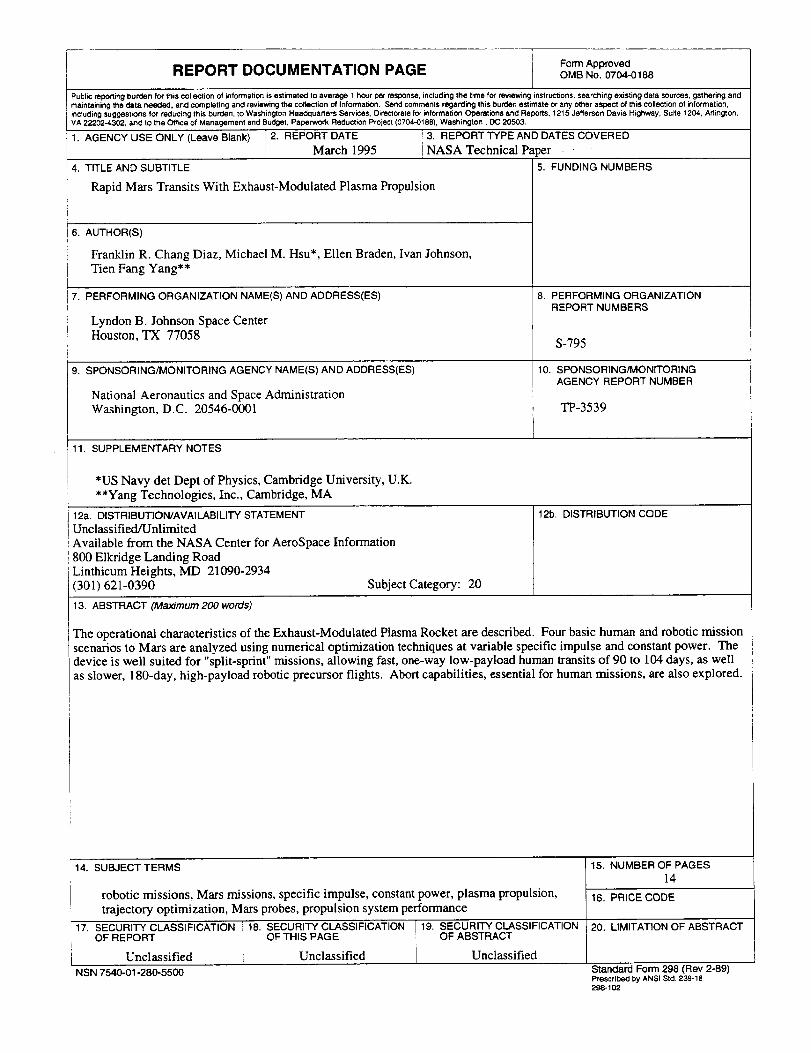
13. ABSTRACT (Maximum 200 words)
The operational charaoteristics of the Exhaust-Modulated Plasma Rocket are described. Four basic human and robotic mission
scenarios to Mars are analyzed using numerical optimization techniques at variable specific impulse and constant power. The
device is well suited for "split-sprint" missions, allowing fast, one-way low-payload human transits of 90 to 104 days, as well
as slower, 180-day, high-payload robotic precursor flights. Abort capabilities, essential for human missions, are also explored.
14. SUBJECT TERMS
robotic missions, Mars missions, specific impulse, constant power, plasma propulsion,trajectory optimization, Mars probes, propulsion system performance
17. SECURITY CLASSIFICATION 18. SECURITY CLASSIFICATION T19. SECURITY CLASSIFICATION
OF REPORT OF THIS PAGE 1 OF ABSTRACTUnclassified Unclassified Unclassified
NSN 7540-01-280-5500
15, NUMBER OF PAGES14
16. PRICE CODE
-_. LIMITATION OF ABSTRACT
Standard Form 298 (Rev 2-89)Preseriped by ANSI Std, 239-18
298-102


