RANGER PLUS LTRP ULTRASONIC LEVEL TRANSMITTER - … · The Ranger Plus™ Ultrasonic Level Sensor...
32
(877) 356-5463 | (p) 330-331-7331 | (f) 330-331-7172 | www.FLO-CORP.com | © 2017 FLO-CORP | REVA 1116 1 RANGER PLUS ™ LTRP ULTRASONIC LEVEL TRANSMITTER OPERATING INSTRUCTIONS
Transcript of RANGER PLUS LTRP ULTRASONIC LEVEL TRANSMITTER - … · The Ranger Plus™ Ultrasonic Level Sensor...

(877) 356-5463 | (p) 330-331-7331 | (f) 330-331-7172 | www.FLO-CORP.com | © 2017 FLO-CORP | REVA 1116 1
RANGER PLUS™ LTRPULTRASONIC LEVEL TRANSMITTER
OPERATING INSTRUCTIONS

(877) 356-5463 | (p) 330-331-7331 | (f) 330-331-7172 | www.FLO-CORP.com | © 2017 FLO-CORP | REVA 1116 2
Principle of OperationPlease read carefully! No liability can be accepted for damage caused by improper use or installation of the Ranger Plus™ Level Transmitter.
The Ranger Plus™ Ultrasonic Level Sensor provides accurate non-contacting level measurement up to 35 feet and features (3) Analog Outputs and (2) Switches. The analog output modes are 0-10 VDC, 4-20mA Sinking and 4-20mA Sourcing. The switches are configurable as either “PNP” or “NPN” type (sourcing or sinking). Each has an adjustable set point, hysteresis, window, initial conditions, ON delay, OFF delay and loss of target response to easily create controls and alarms. The sensor is housed in a chemically inert PVDF sealed housing for durability and long life. The sensor is well suited for a wide range of corrosive, sticky or dirty type media. The Ranger Plus™ applications include pump control, bulk inventory, batch processing, water management, high/low level alarms and much more. To configure, monitor and data log your application, download the free Ranger Plus™ software and purchase one RS-485 communication tool. Safety PrecautionsIf you are unsure of the suitability of a Ranger Plus™ Ultrasonic Level Transmitter for your installation, please consult your FLO-CORP representative for further information.
NOTE: REMOVE ALL PACKING INSERTS BEFORE OPERATING LEVEL TRANSMITTER.
Authorized PersonnelAll operations described in this operating instructions manual must be carried out only by trained specialist personnel authorized by the plant operator. During work on and with the device the required personal protection equipment must always be worn.
Warning about misuseInappropriate or incorrect use of the instrument can give rise to application-specific hazards, e.g. vessel over fill or damage
to system components through incorrect mounting or adjustment.
General Safety InstructionsThe user must take note of the safety instructions in this operating instructions manual , the country specific installation
standards as well as all prevailing safety regulations and accident prevention rules. The instrument must only be operated in a technically flawless and reliable condition. The operator is responsible for trouble-free operation of the instrument. During the entire duration of use, the user is obliged to determine the compliance of the required occupational safety measures with the current valid rules and regulations and also take note of new regulations.
DisclaimerThe information contained in this document is subject to change without notice. FLO-CORP makes no representations or warranties with respect to the contents hereof and specifically disclaims any implied warranties of merchantability or fitness for a particular purpose.

(877) 356-5463 | (p) 330-331-7331 | (f) 330-331-7172 | www.FLO-CORP.com | © 2017 FLO-CORP | REVA 1116 3
Specifications are subject to change without notice.
FEATURES & BENEFITS
APPLICATION PHOTO
• Unaffected by optical factors like color and transparency• Computer (PC) software allows remote adjustment• Standard RS-485 Serial Interface• Durable housing for long life• Threaded at both ends• Optional Threaded Jam Nut in applications where no
threaded fitting is available• Short & Overload protected I/O• Adjustable filters compensate for tank mixers or
turbulence• Temperature compensation for improved accuracy• Adjustable sensitivity• 4.0” to 12.0” deadband
SPECIFICATIONS
Active Measuring Range LTRP-10: 2.5” - 120”LTRP-35: 12” - 420”
Case Material PVDF
Temperature -40 to 158ºF (-40 - 70ºC)
Humidity 0 to 100% operating
Compensation Temperature Compensated
ResolutionDigital: 0.0034” (0.086mm); Analog: 4099 steps (over full 0-10 VDC or 0-20 mA)
RepeatabilityGreater of ±0.03” (0.76mm) or 0.1% of target distance in stable environment
Update Rate50 ms, software adjustable; affected by software filter selections
Input Power 10-30 VDC, 50 mA maximum (not including output currents)
Voltage Output 0-10, 0-5 VDC or PC customized; 10mA max. (*)
Current Loop #1 Current sourcing 4-20mA or PC customized, max. loop 500Ω (*)
Current Loop #2 Current sinking 4-20mA or PC customized, max. loop 500Ω (*)
Sinking Switch150 mA max. @ 40 VDC max., teachable set point & polarity, fault indication
Sourcing Switch150 mA max. @ input voltage, teachable set point & polarity, fault indication
Max. Range LTRP-10: 10 feetLTRP-35: 35 feet
Process Mount LTRP-10: 1.5 inchesLTRP-35: 2 inches
Adjustment Ranger Plus™ Software
Configuration Stored in non-volatile memory
Transducer Rugged piezoelectric
Protection NEMA 4X, NEMA 6P, IP68

(877) 356-5463 | (p) 330-331-7331 | (f) 330-331-7172 | www.FLO-CORP.com | © 2017 FLO-CORP | REVA 1116 4 (877) 356-5463 | (p) 330-331-7331 | (f) 330-331-7172 | www.FLO-CORP.com | © 2017 FLO-CORP | REVA 1116 5
CONNECTIONS
CABLE CONNECTION WIRE DESCRIPTION
Power Brown 10 - 30 VDC, 50 mA max (sensitivity reduced below 15 VDC)
Ground Blue Power and interface common
Voltage Output* Violet 0 - 10 VDC, 0-5 VDC or custom range values between 0 and 10 VDC
Current Loop Output* Green 4-20 mA sourcing (adjustable range
values between 0 and 20 mA)
Current Loop Output* Orange 4-20 mA sinking (adjustable range
values between 0 and 20 mA)
Switch #1 Output Black Sinking (“NPN”) or Sourcing (“PNP”), user selected
Switch #2 Output White Sinking (“NPN”) or Sourcing (“PNP”), user selected
RS-485 - Gray Serial data connection (depends on model - see model selection)
RS-485 + Yellow Serial data connection (depends on model - see model selection)
Notes
Mounting: Lower 1.5 in. or upper 1 in. NPT threadsAttached Cable: PUR jacket, 6 ft (2m) long
5.59 (142mm)
1.18 (30mm)2.60 (66mm)
DIRECTION OF MEASUREMENT
LOWER MOUNTINGTHREADS 2 INCH NPT
UPPER THREADS1 INCH NPT
3.05 (77mm)
Notes
Mounting: Lower 2 in. Upper 1 in.
Attached Cable: PUR jacket, 6.5 ft (2m) long
Weight: 24.7oz. (0.70kg)
2.22 (56mm)
LTRP-10: (2.5" - 120" Range)
LTRP-35: (12" - 420" Range)

(877) 356-5463 | (p) 330-331-7331 | (f) 330-331-7172 | www.FLO-CORP.com | © 2017 FLO-CORP | REVA 1116 4 (877) 356-5463 | (p) 330-331-7331 | (f) 330-331-7172 | www.FLO-CORP.com | © 2017 FLO-CORP | REVA 1116 5
INSTALLATION
Orient the sensor perpendicular to the liquid surface or target object for best results as shown below. Ultrasound energy must reflect back to the sensor or the sensor will not detect the target, and may detect a later multipath echo (which would “measure” as a lower tank level).

(877) 356-5463 | (p) 330-331-7331 | (f) 330-331-7172 | www.FLO-CORP.com | © 2017 FLO-CORP | REVA 1116 6 (877) 356-5463 | (p) 330-331-7331 | (f) 330-331-7172 | www.FLO-CORP.com | © 2017 FLO-CORP | REVA 1116 7
The sensor mounting location should be chosen so there are no obstacles in the beam path that reflect the ultrasound beam back to the sensor. The sensor can be mounted close to a vertical pipe or tank wall without if the wall or pipe surfaces are smooth (see “Acceptable” above). Make sure that unintended targets between the sensor and liquid surface are not in the sensor’s beam area. Keep the sensor away from horizontal pipes, vertical pipe seams, or tank seams if they are large enough to reflect the ultrasound. The sensor measures to the closest target and will detect submerged equipment if the level drops below the equipment. Position the sensor to avoid these issues (see “Avoid” below).
WIRING
Ground (blue wire)The ground wire is common to both the power supply and the output circuits.
Cable Shield (bare wire)The cable shield is not terminated at the sensor. This wire should be terminated to equipment ground near the user equipment, preferably to a single point ground for all equipment. This is important if thecable is lengthened and/or routed near electrically noisy wiring or equipment.
Power Input (brown wire)Connect a DC power supply to the DC+ (Brown) and GND (Blue) wires. These colors conform to EU standards. Reversing the power connections will not damage the sensor. A power supply voltage between 15-30 VDC is recommended. A +24 VDC supply is a commonly used standard. Target sensitivity and the maximum voltage output value is reduced at power supply voltages below 15 VDC.
Data Connections (gray & yellow)Serial data interfaces are used for:• Configuration• Synchronization• User communications between the sensor and an external data communications device* The Ranger Plus™ requires an RS-232 interface and connect directly to a PC COM port for the Ranger Plus™ Software configuration as shown below.
CABLE CONNECTION WIRE DESCRIPTION
Power Brown 10 - 30 VDC, 50 mA max (sensitivity reduced below 15 VDC)
Ground Blue Power and interface common
Voltage Output* Violet 0 - 10 VDC, 0-5 VDC or custom range values between 0 and 10 VDC
Current Loop Output* Green 4-20 mA sourcing (adjustable range
values between 0 and 20 mA)
Current Loop Output* Orange 4-20 mA sinking (adjustable range
values between 0 and 20 mA)
Switch #1 Output Black Sinking (“NPN”) or Sourcing (“PNP”), user selected
Switch #2 Output White Sinking (“NPN”) or Sourcing (“PNP”), user selected
RS-485 - Gray Serial data connection (depends on model - see model selection)
RS-485 + Yellow Serial data connection (depends on model - see model selection)

(877) 356-5463 | (p) 330-331-7331 | (f) 330-331-7172 | www.FLO-CORP.com | © 2017 FLO-CORP | REVA 1116 6 (877) 356-5463 | (p) 330-331-7331 | (f) 330-331-7172 | www.FLO-CORP.com | © 2017 FLO-CORP | REVA 1116 7
Groups of 2 to 32 sensors can be connected together and time synchronized for these purposes:• Prevent sensors in close proximity from interfering with one another (“cross-talk”)• Enable a group of sensors to measure a common target(s) at the highest possible rate
The Ranger Plus™ sensors have three analog outputs - voltage, sourcing current loop and sinking current loop. They all share the same endpoints and slope (decreasing or increasing with distance.) They are simultaneously available on separate wires.
Voltage Ouput (violet wire)This figure shows a voltage output connection:
SYNCHRONIZATION
ANALOG OUTPUTS

(877) 356-5463 | (p) 330-331-7331 | (f) 330-331-7172 | www.FLO-CORP.com | © 2017 FLO-CORP | REVA 1116 8 (877) 356-5463 | (p) 330-331-7331 | (f) 330-331-7172 | www.FLO-CORP.com | © 2017 FLO-CORP | REVA 1116 9
The default voltage output is a 0 to 10 volt DC signal proportional to the measured distance between the endpoints set by the user. The voltage range limits are adjustable to values between 0 to 10 volts using Ranger Plus™ software. The analog slope can increase or decrease with distance but all analog outputs must have the same slope. The voltage is measured relative the GND (BLUE wire). The 0 to 10 volt endpoint distances affect all voltage and current loop outputs, and can be set anywhere in the sensor’s operating range using Ranger Plus™ Software.
Sourcing Current Loop (green wire)This figure shows a sourcing current loop connection:
The default sourcing loop output is a 4-20mA signal proportional to the measured distance between two endpoints set by the user. The current low/high values are adjustable to any values between 0 and 20mA using Ranger Plus™ Software. The slope can increase or decrease with distance but all analog outputs must have the same slope. In a sourcing loop current flows out of the sensor, through the user equipment and back via the sensor’s ground (BLUE wire).
Sinking Current Loop (orange wire)
The default sinking loop output is a 4-20mA signal proportional to the measured distance between two endpoints set by the user. The current low/high values are Ranger Plus™ Software adjustable and match those of the sourcing loop. Current flows from the power supply through the user equipment then INTO the sensor (ORG wire).
The analog inputs of User Equipment are either differential (both + and - terminals) or single ended (+ and GND terminals). A different input is recommended at the user equipment. If the user equipment is single ended (+ input and GND) the sensor and user equipment cannot share a common ground or the current loop will not work.
(877) 356-5463 | (p) 330-331-7331 | (f) 330-331-7172 | www.FLO-CORP.com | © 2017 FLO-CORP | REVA 1116 8 (877) 356-5463 | (p) 330-331-7331 | (f) 330-331-7172 | www.FLO-CORP.com | © 2017 FLO-CORP | REVA 1116 9
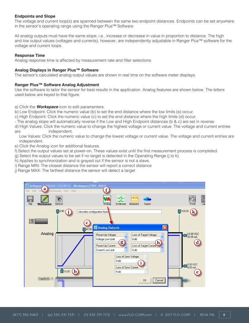
Endpoints and SlopeThe voltage and current loop(s) are spanned between the same two endpoint distances. Endpoints can be set anywhere in the sensor’s operating range using the Ranger Plus™ Software
All analog outputs must have the same slope, i.e., increase or decrease in value in proportion to distance. The high and low output values (voltages and currents), however, are independently adjustable in Ranger Plus™ software for the voltage and current loops.
Response TimeAnalog response time is affected by measurement rate and filter selections.
Analog Displays in Ranger Plus™ SoftwareThe sensor’s calculated analog output values are shown in real time on the software meter displays.
Ranger Plus™ Software Analog AdjustmentUse the software to tailor the sensor for best results in the application. Analog features are shown below. The letters used below are keyed to that figure.
a) Click the Workspace icon to edit paramenters.b) Low Endpoint: Click the numeric value (b) to set the end distance where the low limits (e) occur.c) High Endpoint: Click the numeric value (c) to set the end distance where the high limits (d) occur.- The analog slope will automatically reverse if the Low and High Endpoint distances (b & c) are set in reversed) High Values: Click the numeric value to change the highest voltage or current value. The voltage and current entries are independent. Low Values: Click the numeric value to change the lowest voltage or current value. The voltage and current entries are independent.e) Click the Analog icon for additional features.f) Select the output values set at power-on. These values exist until the first measurement process is completed. g) Select the output values to be set if no target is detected in the Operating Range (j to k).h) Applies to synchronization and is grayed out if the sensor is not a slave.i) Range MIN: The closest distance the sensor will report a correct distancej) Range MAX: The farthest distance the sensor will detect a target

(877) 356-5463 | (p) 330-331-7331 | (f) 330-331-7172 | www.FLO-CORP.com | © 2017 FLO-CORP | REVA 1116 10
The Ranger Plus™ sensors have two solid-state switch outputs. Switch #1 is on the black wire and switch #2 on the white wire. The default switch types are NPN (sinking).The switch type can be selected as either sinking (NPN), sourcing (PNP) or OFF using the Ranger Plus™ Software
Low and High AlarmsThe factory default settings for the switches are typical LOW and HIGH ALARMS. Switch #1 set as a LOW ALARM (switch OFF when level drops below the Optimum range) and Switch #2 set as a HIGH ALARM (switch OFF when level is above a high setpoint). Both levels are adjustable using the Ranger Plus™ Software. The ALARM condition is defined as SWITCH OFF so that a broken alarm wire also causes an alarm. All of this can be altered using the software.
Switch Output VoltageWhen a sinking switch is ON the voltage of the switch wire will be near 0 VDC, and when OFF will be near the voltage of the external “pull-up” source.
When a sourcing switch is ON the voltage of the switch wire will be near the sensor’s power supply voltage and when OFF will be near 0 VDC.
Sinking Switch Output
A sinking switch is an open collector transistor (solid state switch) that sinks current through an external load to GND when ON. The external device can be powered from a source different than the sensor.
SWITCH OUTPUTS

(877) 356-5463 | (p) 330-331-7331 | (f) 330-331-7172 | www.FLO-CORP.com | © 2017 FLO-CORP | REVA 1116 11 (877) 356-5463 | (p) 330-331-7331 | (f) 330-331-7172 | www.FLO-CORP.com | © 2017 FLO-CORP | REVA 1116 12
Sourcing Switch Outputs
A sourcing switch provides current to an external load to turn that load ON or OFF. Current is sourced by the sensor’s power supply, and must be considered when determining the sensor’s maximum current draw.
Switch Response TimeSwitch response times are affected by measurement rate and filter selections.
Switch Displays in Ranger Plus™ SoftwareThe sensor’s switch output states are displayed in real time in the Ranger Plus™ Software

(877) 356-5463 | (p) 330-331-7331 | (f) 330-331-7172 | www.FLO-CORP.com | © 2017 FLO-CORP | REVA 1116 11 (877) 356-5463 | (p) 330-331-7331 | (f) 330-331-7172 | www.FLO-CORP.com | © 2017 FLO-CORP | REVA 1116 12
Ranger Plus™ Software Adjustable Switch Features
Basic and extended features assure optimum system settings and control functions that otherwise require external logic or time delay relays. Each switch has the following configurable features:
• Setpoint (ON switching distance)• Polarity (ON closer or farther than setpoint)• Mode = Setpoint (with Hysteresis) or Window• ON and OFF time delays for state changes• “No Target” state and time delay• Power-up state

(877) 356-5463 | (p) 330-331-7331 | (f) 330-331-7172 | www.FLO-CORP.com | © 2017 FLO-CORP | REVA 1116 13 (877) 356-5463 | (p) 330-331-7331 | (f) 330-331-7172 | www.FLO-CORP.com | © 2017 FLO-CORP | REVA 1116 14
Ranger Plus™ Software Switch AdjustmentsUse the software to tailer the sensor for best results. Switch features are shown below. The letters used below are keyed to that figure. a) Click the Workspace icon to edit parametersb) Setpoint: Click the numeric value to set the distance where the switch turns ON (the switch turns OFF by reverse hysteresis distance (d))c) Click the Switches icon for additional features. d) Hysteresis is the distance the target must move in the reverse direction of the Setpoint to turn OFF.e) The polarity can be either ON CLOSER or ON FARTHER than the Setpoint. This is like setting a normally open or normally closed condition.- Reversing the switch polarity also reverses the hysteresis (d) direction!f) Window is an alternate mode where the switch state is Polarity (h) inside the window (over a range of distances) and the reverse if outside.g) Click these numbers to enter the window SIZE. The size is added to the Setpoint distance to become the far window distance.h) The Polarity can be either ON or OFF for targets within the window. This example shows OFFi) Select the switch state to set at power-on. This state exists until the first measurement process is completed.j) If the sensor looses the target the state can be held or set on or off (after delay k).k) If the sensor looses a target for this time period the no target state (j) is set (0 = immediate)l) Time delays can be required before turning a switch on or off. A switch state is set if a target continuously satisfies that state’s requirements for the full delay time period.m) Applies to synchronization and is grayed out when the sensor is not a SYNC slave.n) Applies to synchronization. Set in the Measure window as it also affects the analogs.o) Range MIN: The closest distance the sensor will report a correct distance.p) Range MAX: The farthest distance the sensor will detect a target.

(877) 356-5463 | (p) 330-331-7331 | (f) 330-331-7172 | www.FLO-CORP.com | © 2017 FLO-CORP | REVA 1116 13 (877) 356-5463 | (p) 330-331-7331 | (f) 330-331-7172 | www.FLO-CORP.com | © 2017 FLO-CORP | REVA 1116 14
The YELLOW and GRAY serial data communication wires are used for three purposes:
1) Setup - connect to a PC running Ranger Plus™ Software for setup, calibration, analysis and rapid sensor cloning.
2) User Applications - connect to an external system and provide distance measurement data. Several operating modes are available.
3) Synchronization (SYNC) - time synchronize a group of 2-32 sensors
The electrical interface is RS485
The Ranger Plus™ sensor uses a serial data RS485 interface that can be used over long distances. A single sensor is shown below connected to an RS485 port. To use Ranger Plus™ Software with the unit the PC must have an RS485 adapter connected. Adapters are available to convert COM or USB ports to RS485.
Up to 32 addressable sensors can be connected to the RS485 bus. Sensors can be configured into RS-485 addressable multi-drop networks as shown below.
Before connecting to a network each sensor must be assigned a unique address and all sensors must be configured to the baud rate of the network controller, as described in following. The address assignments must also be different from other connected (non FLO-CORP) devices. Sensors used in a network must be configured in continuous or start-on-poll measurement activation depending on the needs of the system.
SERIAL DATA INTERFACE

(877) 356-5463 | (p) 330-331-7331 | (f) 330-331-7172 | www.FLO-CORP.com | © 2017 FLO-CORP | REVA 1116 15 (877) 356-5463 | (p) 330-331-7331 | (f) 330-331-7172 | www.FLO-CORP.com | © 2017 FLO-CORP | REVA 1116 16
Power UpThe following occurs within 1200 ms of power ON:• Outputs are set to their power-up states• Sensor begins first measurement or becomes available for start-on-poll activation• The analog and switch outputs are set, and distance data becomes available, after completing the first measurement process
All sensor outputs remain in their power-up conditions until the first measurement process has completed.
Measurement ActivationSensor measurements can be activated in two ways – continuous or start-on-poll. The factory default and most common is continuous. The activation options are set using the software by clicking the Measure icon then using the Measurement Activation selector.
Sensor features affected by the activation mode are summarized the Table below.
OPERATION
Activation SelectionIn the Ranger Plus™ software, click the Measure icon then locate the following Measurement Activation drop down menu:

(877) 356-5463 | (p) 330-331-7331 | (f) 330-331-7172 | www.FLO-CORP.com | © 2017 FLO-CORP | REVA 1116 15 (877) 356-5463 | (p) 330-331-7331 | (f) 330-331-7172 | www.FLO-CORP.com | © 2017 FLO-CORP | REVA 1116 16
OPERATING RANGE
Continuous ActivationThis is the factory default. Measurements repeat continuously at the measurement interval. The analog and switch outputs are updated, and the distance data is stored at the end of each measurement process. At any time a serial data controller can retrieve the last stored distance data by issuing a serial data read poll without effecting ongoing measurements. Continuous mode is generally used unless:• There is an advantage to having the sensors measure only on request (see Start on Poll)• Multiple sensors are connected in a synchronized group
Start on Poll ActivationMeasurement begins when the sensor receives a serial data distance read poll from an external controller (or Ranger Plus™ software). Upon completing the measurement process the analog and switch outputs are updated, the distance measurement stored, and the sensor stops measuring.
The Ranger Plus™ software detects start-on-poll mode when the Sensor icon is clicked, and displays polling controls in the upper right corner of the screen.
The sensor measures the distance to targets within the Operating Range (target 1 to target 2). This range can be set through the software by adjusting the Range MIN and Range MAX parameters. The factory default is the widest possible, deadband to maximum range.

(877) 356-5463 | (p) 330-331-7331 | (f) 330-331-7172 | www.FLO-CORP.com | © 2017 FLO-CORP | REVA 1116 17 (877) 356-5463 | (p) 330-331-7331 | (f) 330-331-7172 | www.FLO-CORP.com | © 2017 FLO-CORP | REVA 1116 18
Range MinThe Range MIN is the closest distance that the sensor will report an accurate distance. Targets closer than Range MIN may be detected, especially at close range, but the measured distance will be Range MIN (or greater for secondary echoes). If the near distance is important, keep the target beyond Range MIN.
Range MaxThe Range MAX is the farthest distance that the sensor will detect a target. Targets farther than Range MAX are ignored. If a target is not detected closer than Range MAX a “No Target” condition exists. The Ranger Plus™ software prevents setting the Range MAX parameter to a value greater than Maximum Range.
Under “No Target” conditions the analog and switch output values or states can be configured to either hold their prior or set specific values or states, either immediately or after adjustable time periods.
The “No Target” controls can be an important and useful tool to control system response by limiting the distance the sensor will consider a target valid.
Factory DefaultsThe factory default range values are:• Range MIN = deadband• Analog far setpoint = Optimum range• Range MAX = Maximum Range
The measurement process includes the raw distance measurement, followed by one or more filter options, then any switch time delays before the result is reflected in the sensor outputs.
MEASUREMENT PROCESS

(877) 356-5463 | (p) 330-331-7331 | (f) 330-331-7172 | www.FLO-CORP.com | © 2017 FLO-CORP | REVA 1116 17 (877) 356-5463 | (p) 330-331-7331 | (f) 330-331-7172 | www.FLO-CORP.com | © 2017 FLO-CORP | REVA 1116 18
In Start on Poll activation the entire process is performed once per poll, i.e., M Input Rejection x N Averaging measurements. Some filters are disallowed in Start on Poll. If a poll is received before an ongoing measurement process finishes, the ongoing process will run to completion then another measurement process will begin.
Switch time delays can be set to implement special control functions. The most recent distance result can also be requested by an external controller over the serial data bus.
When connected to a sensor (Sensor icon clicked), distance measurements are viewed in The Ranger Plus™ Software in several ways. The software obtains the measurements via serial data interface requests in the continuous or start-on-poll mode. The values or states of the selected output(s) are also displayed.
Sensor ScreenConnect the software to the sensor (menu: Sensor – Connect). The software automatically selects the Sensor icon displays the distance in real-time with a repositioning target symbol , shows analog output value(s) on meters and shows switch state(s) as symbols . Additional display icons offer features described below.
Large DisplayClick the Large icon to pop up a large digital display that can be viewed from afar.
SENSOR VIEWING
(877) 356-5463 | (p) 330-331-7331 | (f) 330-331-7172 | www.FLO-CORP.com | © 2017 FLO-CORP | REVA 1116 19 (877) 356-5463 | (p) 330-331-7331 | (f) 330-331-7172 | www.FLO-CORP.com | © 2017 FLO-CORP | REVA 1116 20
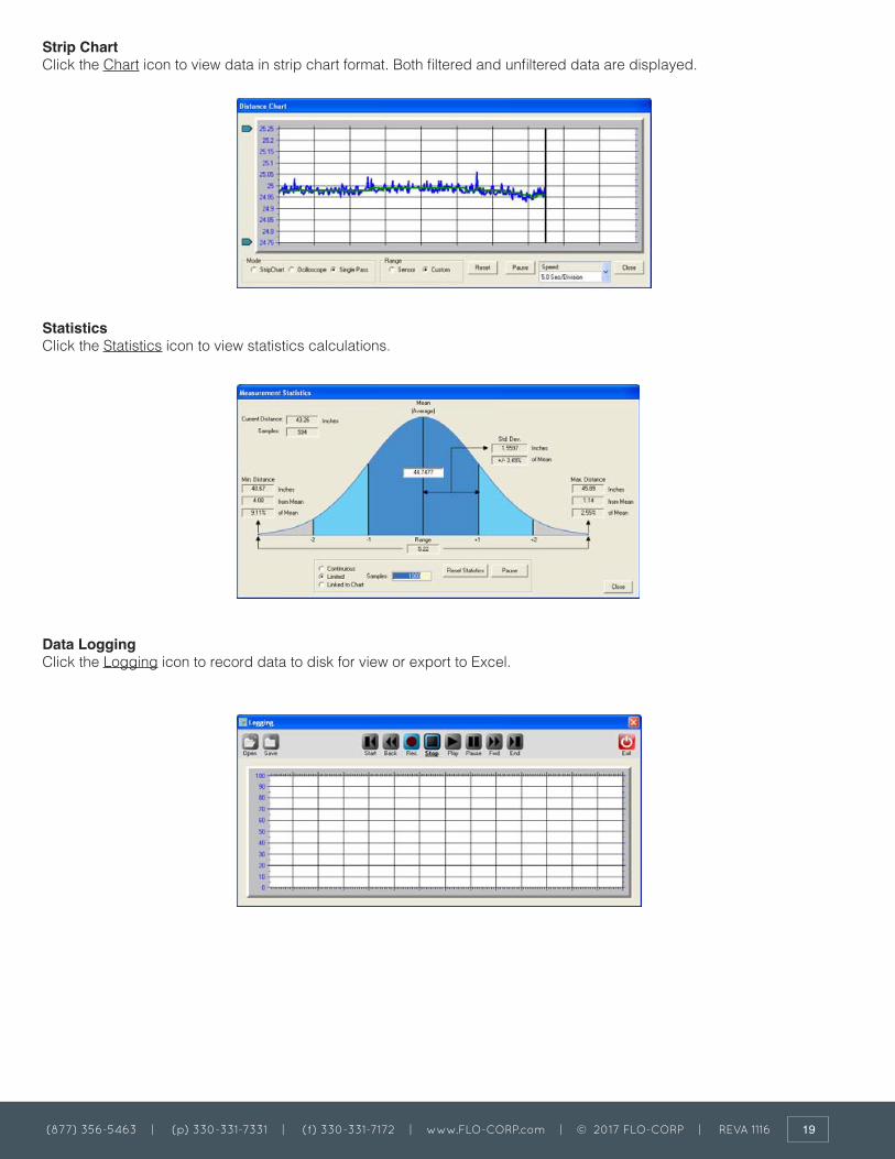
Strip ChartClick the Chart icon to view data in strip chart format. Both filtered and unfiltered data are displayed.
StatisticsClick the Statistics icon to view statistics calculations.
Data LoggingClick the Logging icon to record data to disk for view or export to Excel.

(877) 356-5463 | (p) 330-331-7331 | (f) 330-331-7172 | www.FLO-CORP.com | © 2017 FLO-CORP | REVA 1116 19 (877) 356-5463 | (p) 330-331-7331 | (f) 330-331-7172 | www.FLO-CORP.com | © 2017 FLO-CORP | REVA 1116 20
MEASUREMENT RATEThe measurement rate is how often the sensor measures the target distance. It does not require adjustment in most applications.
To accommodate special requirements the rate can be adjusted from .0001 to 200 meas./sec (measurement intervals from 2.78 hours to 5 ms) using the software.
Maximum Target Distance EffectsThe time required to detect a target is determined by the speed of sound. Sound travels at about 1 ms/ft. (3.3 ms/meter) so a target at 10 feet (3m) results in an echo delay of about 20 ms (the sound has to travel out then back). If the measurement interval is less than that time the target echo will go undetected, or may be detected in the next cycle, causing erratic measurements.
The maximum distance a sensor can detect a target is the shorter of (a) the sensor model’s maximum range, (b) the user-adjustable RangeMAX parameter, or (c) the farthest distance a target echo can return before the next measurement begins (measurement rate limited). Setting the measurement interval faster than the default may restrict the maximum detectable target distance (see below table).
Measurement Stability EffectsIf the measurement rate is set too fast the sensor may detect delayed echoes from a prior measurement cycle, causing measurement instability. This is more common at short distances but can also occur in large liquid tanks.
A delayed echo can be a more distant target or a multi-bounce echo from the primary target (echoes can bounce back and forth between two surfaces).
This effect is also more prevalent at cold temperatures because sound absorption in air is lower and it takes longer for the echoes to decay.
Multi-echo issues are minimized by slowing the measurement rate, reducing the sensitivity, and/or using materials to absorb or deflect the ultrasound.

(877) 356-5463 | (p) 330-331-7331 | (f) 330-331-7172 | www.FLO-CORP.com | © 2017 FLO-CORP | REVA 1116 21 (877) 356-5463 | (p) 330-331-7331 | (f) 330-331-7172 | www.FLO-CORP.com | © 2017 FLO-CORP | REVA 1116 22
OUTPUT RESPONSE TIME
FILTERS
The default response time for all outputs is the measurement interval. The analog, switch and serial ASCII streaming (if enabled) outputs are updated after each measurement cycle.
The response time is affected by several sensor user- adjustable features using The Ranger Plus™ Software:1. The measurement rate can be used to directly increase or decrease response time.2. Filters can be selected to process measurements for improved stability. Some filters update outputs after each measurement interval while others require several intervals. Filters can decrease response time.3. Time Delays can be used to create system responses that might otherwise require external controllers or time delay relays. They directly delay the response of the output(s) to which they are applied. The factory default settings are listed in Filters and Time Delays.
Filters are processing features that reject and/or smooth measurements, and/or limit the rate of change of the sensor distance (and therefore outputs). Their purpose is to improve sensor performance in real- world applications. The factory default has a running average of 50 enabled to slow down the response to liquid level fluctuations.OverviewThe below figure shows the flow of distance measurements through the filters to the outputs. Filters are applied in order of flow from left to right (input to output). None or one selection can be made from each category (Input Rejection, Averaging and Distance Limiting). As filters are enabled the output response time is generally slower. Some filter settings are not usable in applications requiring a fast response time.
Filter SelectionClick the Measure icon on the main screen to open the Measurements window. The location of the Filter Options is shown below.
When using filters, the first valid measurement after power ON becomes the initial condition for all further processing. The Filter Options are shown in block diagram below, followed by a description of each.

(877) 356-5463 | (p) 330-331-7331 | (f) 330-331-7172 | www.FLO-CORP.com | © 2017 FLO-CORP | REVA 1116 21 (877) 356-5463 | (p) 330-331-7331 | (f) 330-331-7172 | www.FLO-CORP.com | © 2017 FLO-CORP | REVA 1116 22
Input Rejection FiltersInput rejection filters ignore some measurements. The input to these filters is the raw sensor distance measurement. The output (“Good” data) is then input to a averaging filter (if used).
Closest of M MeasurementsThe sensor performs M distance measurements and rejects all except the closest. The number of samples (M) can be set to any value from 2 to 999. The response time is slowed by a factor of M. For example, if M=3 and the measurement interval is 50 ms the response time is 150 ms (not including any successive filters or switch time delays).
This filter is useful for applications where the desired result if the closest object detected in a given period of time. Examples include detecting the peak value of material flowing on a conveyor, or maintaining a measurement value of a poor target (weak or intermittent echo).
Farthest of M MeasurementsThe sensor performs M distance measurements and rejects all except the farthest. It is otherwise identical to the Closest of M filter described above.
This filter is useful to ignore an unintended or unwanted target that occasionally passes between the sensor and the intended target. Examples include ignoring mixer blades in tanks, ignoring traversing objects not the intended target, or rejecting sporadic interference (electrical, physical or acoustic).
X of Y Filter (Stability)At least X measurements of the previous Y must be within +/- 6.25% of the latest measurement. All measurements are ignored until this condition is satisfied, i.e., the target must remain stable before the sensor will process it. If the target remains unstable a new distance measurement will never be established.
Instability is different from the “no target” condition. A perfectly detected target may be in motion and thereby unstable.
The degree of stability required is user adjustable by changing the values of X and Y. The range of values for X is 1 to 7 and for Y is 2 to 7.
As long as each new measurement X falls within bounds the sensor response time is unaffected and the latest X is available for output (excluding averaging and switch time delays used). If the input data fall out of bounds then a delay will occur before the filter criteria can again be satisfied. The delay for a re- stabilized target could range from 1 to X measurement intervals depending on the history of the prior Y measurements.
This filter is disallowed when using Start on Poll measurement activation.
Averaging FiltersThe averaging filters receive their distance data from the input rejection filters. The averaging filter response time is therefore affected by the rejection filter selections. If an unstable target is detected by the stability filter (x of y), the averaging filter and subsequent processing are suspended at the current distance until stability returns. The distance output of the averaging filters is rate-of-change restricted by a distance restriction filter (if used).
Boxcar AverageThis filter calculates the average of N inputs (N = 2 to 255) passing through the rejection filter. The process is repeated every N inputs. The response time is therefore slowed by a factor of N. For example, if M=3 for a rejection filter and N=10 for the Boxcar average then the update period at a 50 ms measurement interval is 50 x 3 x 10 = 1500 ms.
Running AverageThis filter calculates the average of N inputs (N = 2 to 255) passing through the rejection filter. The average is updated after each input rather than after N inputs as for the boxcar average. The output response of this filter is therefore smoother than the boxcar filter since the output is updated more frequently.
This filter is disallowed when using Start on Poll measurement activation.

(877) 356-5463 | (p) 330-331-7331 | (f) 330-331-7172 | www.FLO-CORP.com | © 2017 FLO-CORP | REVA 1116 23 (877) 356-5463 | (p) 330-331-7331 | (f) 330-331-7172 | www.FLO-CORP.com | © 2017 FLO-CORP | REVA 1116 24
Distance Limiting FiltersThe distance limiting filters clamp the rate of change of measured distance before setting sensor outputs. These filters limit the rate of change of data received from the input rejection and/or averaging filters. The limited distance then drives the sensor outputs (not including switch time delays).
Rate of ChangeA maximum rate of change of distance (∆D/sec) is limited to a maximum value, whether increasing or decreasing. The maximum value is a user-entered parameter with a range of .003 in./sec to 173 in./sec.An example use of this filter is limiting the rate of change allowed when driving a motor or other mechanical system.
Slow-FastIf the target position changes quickly, the sensor assumes it is a false change but starts to recalculate slowly toward the new position. If the new position remains stable the sensor gradually increases the rate of change of measurement toward the new position until it is reached.
This filter is disallowed when using Start on Poll measurement activation.
This filter is used for targets that change position slowly but have occasional interruptions. Examples:• Measuring a roll diameter - holds a stable roll measurement yet readjusts the measurement in a reasonable time during changeovers• Mixer tanks - Ignores rotating mixer blades that pass occasionally between the sensor and liquid.• Ignore unintended targets passing between the sensor and the intended target, such as a traversing mechanism on a printer ink well.
Output Response Time The output update rate is a function of the measurement interval, filter selections and parameters, and switch time delays.
Assuming measurement interval I with a default of 50 ms, here are some example response times:• No filters Response time = I (50 ms)• Closest or Farthest of 20 measurements Response time=I*M=.05*20=1sec• Boxcar Average of 10 measurements Response time = I * N = .05 * 10 = 500 ms• Running Average Response time = I * 1 = 50 ms• Closest of 20 and Boxcar average of 10 Response time = I * M * N = .05 * 20 * 10 Response time = 10 seconds

(877) 356-5463 | (p) 330-331-7331 | (f) 330-331-7172 | www.FLO-CORP.com | © 2017 FLO-CORP | REVA 1116 23 (877) 356-5463 | (p) 330-331-7331 | (f) 330-331-7172 | www.FLO-CORP.com | © 2017 FLO-CORP | REVA 1116 24
Time Delays are used to cause actions that might otherwise require external controllers or time delay relays. They delay the response of the output(s) to which they are applied, and are useful for control and alarm functions. All time delays are adjustable between 0 ms to 5.46 minutes at a 5 ms resolution.
Switch Time DelaysEach switch has 3 independently adjustable delays:• On Delay (default = 0 sec)• Off Delay (default = 0 sec)• No-target Delay (default = 60 sec)
A time delay begins when the condition that triggers it first occurs (a distance measurement that could turn a switch ON or OFF, or no target). Time delays are re-triggered, i.e., the trigger condition must remain active for the full time delay period or the time delay will be reset to zero. If the trigger condition remains for the full time delay period then the corresponding action takes place (switch turns on or off).
Analog “No Target” Time DelayThe analog “no target” delay affects all 3 analog outputs (default = 0 sec). If the no target delay expires the analog outputs are set to their “no target” selections (high value, low value, or no change). The current loop and voltage have independent selections.A time delay begins when the no target condition first occurs. The time delay is re-triggered, i.e., no target must exist for the full time delay period or the time delay will be reset to zero. If the no target condition remains for the full time delay period then the analog outputs are set to their no target values.
At room temperature, a change of 10 degrees will result in approximately 1% change in the speed of sound and therefore the measured distance. Temperature compensation can be enabled to reduce the impact of temperature changes in some applications. This is accomplished by clicking the software Measure icon and using the Temperature Compensation selector. The default is ENABLED.
The Ranger Plus™ sensors have an internal temperature sensor. In applications where the sensor is continually powered a warm-up period of approximately 30 minutes should be allowed before calibrating. The sensor must be protected from the sun or other forms of radiant or conducted heating. Best performance is obtained when the sensor body tracks the surrounding air temperature.
The sensor will not compensate for rapid temperature changes or for temperature variations between the sensor and target.Temperature compensation is less important if the temperature environment in which the sensor is used remains fairly constant.
• Keep unintended targets from the transducer’s field of view. Keep the beam pattern in mind.• Keep the transducer away from ultrasonic noise sources, such as pressurized air nozzles.• Do not allow material to build up on the sensor face or sensor performance may suffer.
TIME DELAYS
TEMPERATURE COMPENSATION
PRECAUTIONS

(877) 356-5463 | (p) 330-331-7331 | (f) 330-331-7172 | www.FLO-CORP.com | © 2017 FLO-CORP | REVA 1116 25 (877) 356-5463 | (p) 330-331-7331 | (f) 330-331-7172 | www.FLO-CORP.com | © 2017 FLO-CORP | REVA 1116 26
RANGER PLUS™ COMMUNICATION SOFTWARE
The Ranger Plus™ software allows you to select and calibrate sensor outputs; modify sensor features (parameters); view, analyze and/or log measurements for performance evaluation; and save Setups to disk for later recall and application cloning.
InstallationThe software runs on a Windows PC and connects to a sensor via a serial data COM port. Insert the CDROM and run setup.exe and follow the directions.
Application SetupA setup is a particular combination of sensor parameters that you establish for an application. Setups can be created or changed in the software workspace, or moved in/out of the workspace from/to the sensor or file as shown below:
Main ScreenSetup parameteres are viewed on the main screen
Or in pop-up dialogs by clicking one of these icons:
Main Screen ViewThe main screen displays a setup of (a) an attached sensor, (b) a file stored on the computer disk, or (c) the workspace, as selected by these icons:
In this example the Workspace is displaying on the main screen (icon is outlined, with bold underlined title), and the workspace matches the file but not the attached sensor.
If the File icon is grayed out, clicking it will open a window to select a file from the computer disk. If the Sensor icon is

(877) 356-5463 | (p) 330-331-7331 | (f) 330-331-7172 | www.FLO-CORP.com | © 2017 FLO-CORP | REVA 1116 25 (877) 356-5463 | (p) 330-331-7331 | (f) 330-331-7172 | www.FLO-CORP.com | © 2017 FLO-CORP | REVA 1116 26
grayed out, clicking it will open a Sensor Connect dialog to connect a sensor.Moving a SetupSetups can be moved between the Workspace and a disk file, or between the Workspace and a sensor. Movement is accomplished in three ways:
1. Using Icons - use the mouse to either (a) right- drag or (b) shift-left-drag the Workspace icon to either the File or Sensor icon, or vice versa. All movement must be in or out of the workspace. For example, to move the workspace to the sensor drag the Workspace icon as shown below:
2. Using Menu selections:File – Read File to Workspace File – Write Workspace to File Sensor – Move Sensor to Workspace Sensor – Move Workspace to Sensor
3. When connecting a Sensor – When using menu Sensor – The software asks if you want the setup copied to the workspace – click Yes to copy it.
Creating a SetupSetups are created or modified in the workspace. There are 3 ways to create a new Setup:
1. Start with a Factory Default – Click Workspace icon, then select menu: Workspace – Default Settings. Select LVL-100-232. 2. Start with a Sensor – Move a setup from a connected sensor into the workspace.3. Start with a File – Move a previously stored disk file into the workspace. After loading the workspace the parameters can be modified, then moved to a file or sensor. If the setup is not moved it is lost when exiting the software.
Saving a SetupMake the workspace changes you want to test, saving them to the sensor as often as needed until the sensor is operating as needed. When finished, save the workspace to a disk file for future reference or cloning (see Moving a Setup). Use a meaningful filename when saving.

(877) 356-5463 | (p) 330-331-7331 | (f) 330-331-7172 | www.FLO-CORP.com | © 2017 FLO-CORP | REVA 1116 27 (877) 356-5463 | (p) 330-331-7331 | (f) 330-331-7172 | www.FLO-CORP.com | © 2017 FLO-CORP | REVA 1116 28
CONNECTING A SENSOR
The Ranger Plus™ Software requires both a physical and logical sensor-to-PC connection. Physical options include a direct 9-pin COM port connection or USB-to-COM adapter
1. Install a cable between the sensor and COM port. Use the cable included with the software kit or wire it yourself.2. Apply sensor power 3. Logical Connection: Connect the Ranger Plus™ software to the sensor using menu selections Sensor – Connect.
4. The Connect Sensor dialog then appears with either the default values or your previous selections. Make any changes then click Connect:
5. This message confirms a software-to-sensor link:

(877) 356-5463 | (p) 330-331-7331 | (f) 330-331-7172 | www.FLO-CORP.com | © 2017 FLO-CORP | REVA 1116 27 (877) 356-5463 | (p) 330-331-7331 | (f) 330-331-7172 | www.FLO-CORP.com | © 2017 FLO-CORP | REVA 1116 28
Move the parameters to the Workspace to (a) change them or (b) save them to disk. You can also move them later. If you intend to copy an existing Workspace to the sensor (cloning this sensor) then click No.
The Ranger Plus™ software then connects to the sensor (Sensor icon automatically selected) and offers sensor viewing.
6. If the following message appears check the (a) wiring, (b) power and (c) interface selections, or use Find Sensor to scan all sensor addresses:
7. If the above error continues, use Find Sensor to scan all sensor interface combinations. The default is address is 1. Check the “All Ports” and/or “All Baud Rates” boxes if you are unsure of those. The software will identify the first Sensor Model found, starting at address 1 through 247. The window will appear as follows as the software searches for a sensor:
8. When a sensor is found this message appears:
Click OK and the Connect Sensor dialog is redrawn with the correct paramenters (step 4).
TROUBLE SHOOTING: Cannot find the sensor - Check the following:• Is the power ON?• Check the wiring connections

(877) 356-5463 | (p) 330-331-7331 | (f) 330-331-7172 | www.FLO-CORP.com | © 2017 FLO-CORP | REVA 1116 29 (877) 356-5463 | (p) 330-331-7331 | (f) 330-331-7172 | www.FLO-CORP.com | © 2017 FLO-CORP | REVA 1116 30
OUTPUTS
After connecting a sensor, click this icon to reconfigure the outputs.
The following 9-wire dialog appears, making it possible to reconfigure the switch outputs type to sinking (NPN), sourcing (PNP) or OFF.
Make output changes before connecting your equipment. Do not change outputs when connected to operating equipment!
If wiring changes are made and the OK button clicked, the changes are made and the sensor automatically disconnects from the software:
Reconnect software to the sensor and resume with new outputs.

(877) 356-5463 | (p) 330-331-7331 | (f) 330-331-7172 | www.FLO-CORP.com | © 2017 FLO-CORP | REVA 1116 29 (877) 356-5463 | (p) 330-331-7331 | (f) 330-331-7172 | www.FLO-CORP.com | © 2017 FLO-CORP | REVA 1116 30
Analog DialogTo modify analog output features not available on the Main Screen, click this icon to display the Analog dialog.
Switch DialogTo modify switch output features not available on the Main Screen, click this icon to display the Switch dialog.
Measure DialogTo modify measurement parameters not available on the Main Screen, click this icon to display the Measure dialog.

(877) 356-5463 | (p) 330-331-7331 | (f) 330-331-7172 | www.FLO-CORP.com | © 2017 FLO-CORP | REVA 1116 31 (877) 356-5463 | (p) 330-331-7331 | (f) 330-331-7172 | www.FLO-CORP.com | © 2017 FLO-CORP | REVA 1116 32
SENSOR ADJUSTMENT
Sensor setups are made in the workspace then transferred to the sensor. The screen shot below shows the screen with the Workspace icon selected.
(a) Setups can be moved between the Workspace and a disk file or sensor
Setup changes do not take effect until moved to the sensor! Remember to save setups to disk for future recall.
(b) Click one of these ICONS for extended features associated with the analog outputs, switch outputs or measurements.
(c) Enter up to 32 characters to describe a setup. This reminder text is stored in the sensor or disk file when the parameters are moved or saved.
(d) Click the distance text to edit the Operating Range. Range MIN is the left parameter and Range MAX the right, e.g., clicking the 4.00 inch (left) value yields:
Enter a new value then type <Enter>.
(e) Click the distance text of high and/or low analog endpoints to calibrate the analog outputs. The voltage and current outputs share the endpoints.
(f) Click text of the high and/or low values to change the output range. The voltage and current loop outputs are independently adjustable.
(g) Click the distance text of the switch setpoints to calibrate the switch ON distances. Hysteresis and window options are found by clicking the Switches icon.
(h) These icons are grayed out in Workspace but operate when connected to a sensor (click Sensor icon).
(i) Equality symbols indicate whether the Workspace is equal or not to the File and Sensor.

(877) 356-5463 | (p) 330-331-7331 | (f) 330-331-7172 | www.FLO-CORP.com | © 2017 FLO-CORP | REVA 1116 31 (877) 356-5463 | (p) 330-331-7331 | (f) 330-331-7172 | www.FLO-CORP.com | © 2017 FLO-CORP | REVA 1116 32
Ordering InformationFLO-CORP MODEL NUMBER BUILDER For Assistance Call 877.356.5463
Use the diagram below, working from left to right to construct your FLO-CORP Model Number. Simply match the category number to the corresponding box number.Example: LTRP-10-N Ranger Plus™ Ultrasonic Level Transmitter (up to 10ft range) with no mounting options
Ordering Notes:(1) Select the best configuration based on your requirements. The LTRP-10 has a 1.5” NPT Process Connection. The LTRP-35 has a 2” NPT Process Connection.(2) Jam nuts are used on the lower threads of an LTRP sensor in applications where there is no threaded fitting available.(3) Consult factory for flange mounting option(4) For wireless monitoring option add Guardian 1000™ when ordering
Wireless Monitoring Option (4)(Ranger Plus with Guardian 1000™ shown)
Standard Ranger Plus™ Shown
To configure, monitor and data log your application, download the free Ranger Plus™ software and purchase one RS-485 communication tool. Add part number LTCT to purchase order.
LTRPMeasuring Range (1)10) LTRP-10: (2.5” - 120” measuring range)35) LTRP-35: (12” - 420” measuring range)
Mounting Options (2)(3)N) NoneT) Threaded Jam Nut ((LTRP-10 = 1.5in) (LTRP-35 = 2in)F) Flange
LTRP