Ultrasonic Measurement of Aircraft Strut Hydraulic Fluid Level
BA00388F/00/EN/13.12
71164377
Description of Instrument Functions
Prosonic T FMU30
Ultrasonic Level Measurement
Short instructions
2 Endress+Hauser
Short instructions
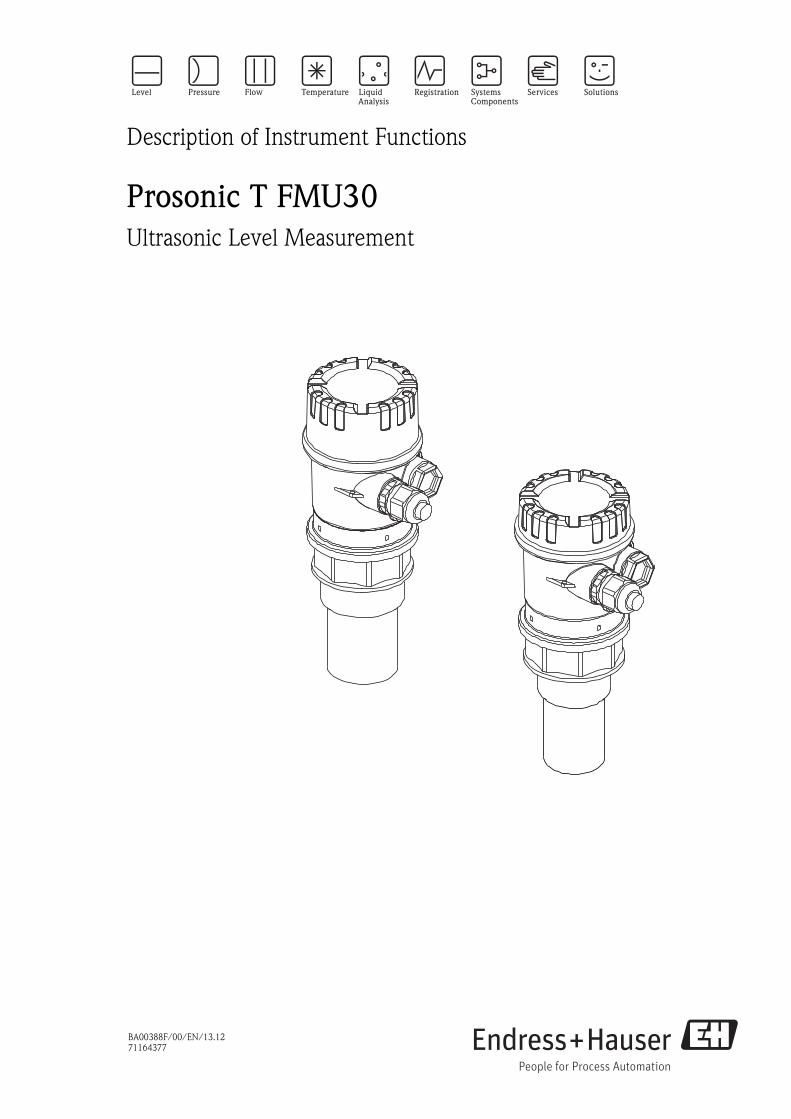
Contents of the operating instructions
This operating instructions contain all functions off the Prosonic T FMU30 operating menu.
Information on mounting, wiring, trouble shooting and maintenance can be found in the document BA00387F/00/EN.
These documents can be found on the CD-ROM "Device Desriptions + Documentation".
F
L
D
E
… …
KA290F/00/A2/12.09
71106912
BD
… …
100%
0%
100333
… …
… …
71106912
SD
Prosonic T - Quick Setup
- domeceiling
- horizontalcyl.
- bypass…
- unknown- liquid- > 4 mm
- < 4 mm(> 0.16 in)
( 0.16 in)<
- standard- calmsurface
- add. agitator…
input E(see sketch)
input F(see sketch)
- ok- too small- too big- unknown- manual
displayed(see sketch)
D and L are confirm
or specifyrange
suggestion
000measured value
Groupselection
00basic setup
01safety settings
0Csystemparameter
0EEnvelope curve
04linearisation
05extended calibr.
06output
0Adiagnostics
0A0presenterror
002tank shape
004processcond.
005emptycalibr.
006fullcalibr.
008dist./meas value
051checkdistance
003mediumproperty
052range ofmapping
053startmapping
008dist./meas value
0E1plot settings
0E2recordingcurve
0A1previouserror
0A4unlockparameter
03temperature
09display
092language
BD: blocking distance
and : increase contrast
and : decrease contrast
0A3reset
0C0tag no.
SD: safety distance
Prosonic T Table of contents
Endress+Hauser 3
Table of contents
1 Notes on use . . . . . . . . . . . . . . . . . . . . 5
1.1 Using the table of contents to locate a function
description . . . . . . . . . . . . . . . . . . . . . . . . . . . . . . . 5
1.2 Using the graphic of the function menu to locate a
function description . . . . . . . . . . . . . . . . . . . . . . . . . 5
1.3 Using the index of the function menu to locate a
function description . . . . . . . . . . . . . . . . . . . . . . . . . 5
2 Function menu . . . . . . . . . . . . . . . . . 13
3 Function group "basic setup" (00) . . . 15
3.1 Function "measured value" (000) . . . . . . . . . . . . . . 15
3.2 Function "tank shape" (002) . . . . . . . . . . . . . . . . . 15
3.4 Function "process cond." (004) . . . . . . . . . . . . . . . 16
3.6 Function "blocking dist." (059) . . . . . . . . . . . . . . . 18
3.8 Display (008) . . . . . . . . . . . . . . . . . . . . . . . . . . . . 19
3.10 Function "range of mapping" (052) . . . . . . . . . . . . 21
3.11 Funktion "start mapping" (053) . . . . . . . . . . . . . . . 21
4 Function group "safety settings" (01). 23
4.1 Function "output on alarm" (010) . . . . . . . . . . . . . 23
4.2 Function "output on alarm" (011) . . . . . . . . . . . . . 24
4.4 Function "ramp %span/min" (013) . . . . . . . . . . . . 26
4.5 Function "delay time" (014) . . . . . . . . . . . . . . . . . . 26
4.7 Function "in safety dist." (016) . . . . . . . . . . . . . . . . 27
5 Function group "temperature" (03) . . 31
5.1 Function "measured temp." (030) . . . . . . . . . . . . . 31
5.2 Function "max. temp. limit" (031) . . . . . . . . . . . . . 31
5.3 Function "max. meas. temp." (032) . . . . . . . . . . . . 31
5.5 Function "defect temp. sens." (034) . . . . . . . . . . . . 32
6 Function group "linearisation" (04) . . 33
6.1 Function "level/ullage" (040) . . . . . . . . . . . . . . . . . 33
6.5 Function "input level" (044) . . . . . . . . . . . . . . . . . . 39
6.7 Function "max. scale" (046) . . . . . . . . . . . . . . . . . . 40
6.8 Function "diameter vessel" (047) . . . . . . . . . . . . . . 40
7 Function group "extended calibr." (05) .
41
7.1 Function "selection" (050) . . . . . . . . . . . . . . . . . . . 41
7.2 Function "check distance" (051) . . . . . . . . . . . . . . 41
7.3 Function "range of mapping" (052) . . . . . . . . . . . . 42
7.4 Function "start mapping" (053) . . . . . . . . . . . . . . . 42
7.5 Function "pres. map dist." (054) . . . . . . . . . . . . . . . 43
7.7 Function "echo quality" (056) . . . . . . . . . . . . . . . . 44
7.8 Function "offset" (057) . . . . . . . . . . . . . . . . . . . . . 45
7.9 Function "output damping" (058) . . . . . . . . . . . . . . 45
7.10 Function "blocking dist." (059) . . . . . . . . . . . . . . . 45
8 Function group "output" (06) . . . . . . . 47
8.1 Function "thres. main val." (062) . . . . . . . . . . . . . . 47
8.2 Function "curr. output mode" (063) . . . . . . . . . . . . 47
8.3 Function "fixed cur. value" (064) . . . . . . . . . . . . . . 48
8.5 Function "simulation value" (066) . . . . . . . . . . . . . 50
8.6 Function "output current" (067) . . . . . . . . . . . . . . . 50
8.7 Function "4mA-value" (068) . . . . . . . . . . . . . . . . . 50
8.8 Function "20mA-value" (069) . . . . . . . . . . . . . . . . 50
9 Function group "Envelope curve" (0E) 51
9.1 Function "plot settings" (0E1) . . . . . . . . . . . . . . . . . 51
9.2 Function "recording curve" (0E2) . . . . . . . . . . . . . . 51
10 Function group "display" (09) . . . . . . . 55
10.1 Function "language" (092) . . . . . . . . . . . . . . . . . . . 55
10.2 Function "back to home" (093) . . . . . . . . . . . . . . . 55
10.4 Function "no.of decimals" (095) . . . . . . . . . . . . . . . 56
10.5 Function "sep. character" (096) . . . . . . . . . . . . . . . 56
10.6 Function "display test" (097) . . . . . . . . . . . . . . . . . 56
11 Function group "diagnostics" (0A) . . . 57
11.2 Function "previous error" (0A1) . . . . . . . . . . . . . . . 58
11.3 Function "clear last error" (0A2) . . . . . . . . . . . . . . . 58
11.6 Function "measured dist." (0A5) . . . . . . . . . . . . . . . 61
11.7 Function "measured level" (0A6) . . . . . . . . . . . . . . 61
11.8 Function "detection window" (0A7) . . . . . . . . . . . . 62
12 Function group "system parameters" (0C)
65
12.1 Function "tag no." (0C0) . . . . . . . . . . . . . . . . . . . . 65
12.2 Function "protocol+sw-no." (0C2) . . . . . . . . . . . . . 65
12.3 Function "serial no." (0C4) . . . . . . . . . . . . . . . . . . . 65
12.5 Function "temperature unit" (0C6) . . . . . . . . . . . . . 66
13 Function group "service" (0D). . . . . . . 69
14 Signal evaluation . . . . . . . . . . . . . . . . . 71
14.1 Envelope curve . . . . . . . . . . . . . . . . . . . . . . . . . . . 71
15 Trouble shooting . . . . . . . . . . . . . . . . . 75
15.1 System error messages . . . . . . . . . . . . . . . . . . . . . . 75
Index function menu . . . . . . . . . . . . . . . . . . 79

Table of contents
4 Endress+Hauser
1 Notes on use
Endress+Hauser 5
1 Notes on use
You have various options for accessing the descriptions of instrument functions or how to enter
parameters.
1.1 Using the table of contents to locate a function
description
All the functions are listed in the table of contents sorted by function group (e.g. basic setup,
safety settings, etc.). You can access a more detailed description of a function by using a page
reference / link.
The table of contents is on ä 3.
1.2 Using the graphic of the function menu to locate a
function description
This guides you step by step from the highest level, the function groups, to the exact function
description you require.
All the available function groups and instrument functions are listed in the table ( ä 79). Select
your required function group or function. You can access an exact description of the function group
or function by using a page reference.
1.3 Using the index of the function menu to locate a
function description
To simplify navigation within the function menu, each function has a position which is shown in
the display. You can access each function via a page reference in the function menu index
( ä 79) which lists all the function names alphabetically and numerically.
1 Notes on use
6 Endress+Hauser
1.4 General structure of the operating menu
The operating menu is made up of two levels:
• Function groups (00, 01, 03, …, 0A, 0C):
The individual operating Selection of the instrument are split up roughly into different function
groups. The function groups that are available include, e.g.: "basic setup", "safety settings",
"output", "display", etc.
• Functions (001, 002, 003, …, 0A6, 0C8):
Each function group consists of one or more functions. The functions perform the actual operation
or parameterisation of the instrument. Numerical values can be entered here and parameters can
be selected and saved. The available functions of the “basic setup (00)” function group include,
e.g.: "tank shape (002)",
"medium property (003)", "process cond. (004)", "empty calibr. (005)", etc.
If, for example, the application of the instrument is to be changed, carry out the following proce-
dure:
1. Select the “basic setup (00)” function group.
2. Select the "tank shape (002)" function (where the existing tank shape is selected).
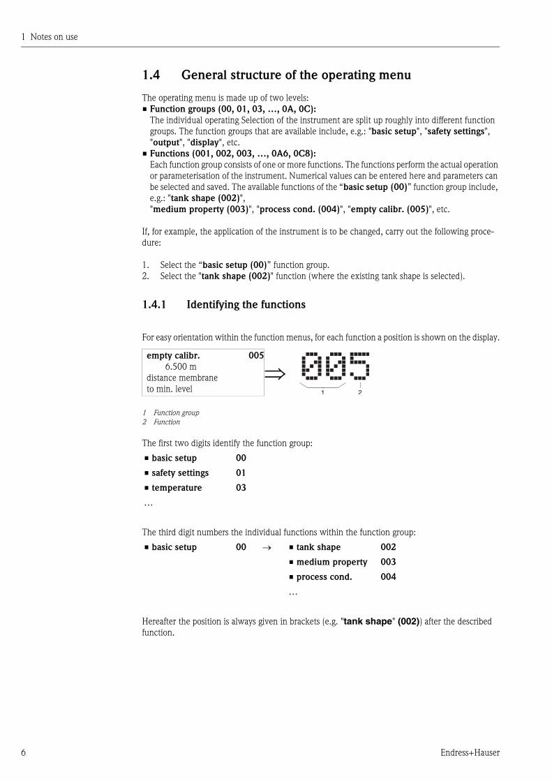
1.4.1 Identifying the functions
For easy orientation within the function menus, for each function a position is shown on the display.
The first two digits identify the function group:
The third digit numbers the individual functions within the function group:
Hereafter the position is always given in brackets (e.g. "tank shape" (002)) after the described
function.
empty calibr. 005
6.500 m
distance membrane
to min. level
1 Function group2 Function
• basic setup 00
• safety settings 01
• temperature 03
…
• basic setup 00 • tank shape 002
• medium property 003
• process cond. 004
…
2
���1
1 Notes on use
Endress+Hauser 7
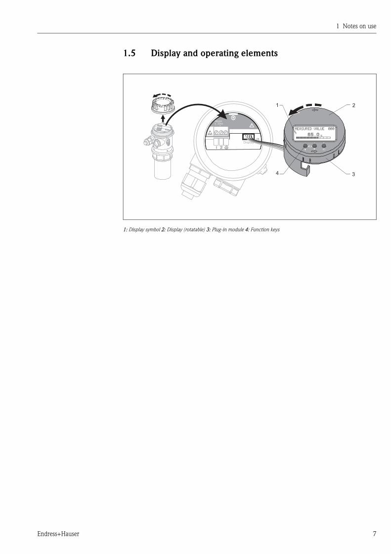
1.5 Display and operating elements
1: Display symbol 2: Display (rotatable) 3: Plug-in module 4: Function keys
4...20mA+
FEU31
-
Display
%
E
1 2
34
1 Notes on use
8 Endress+Hauser
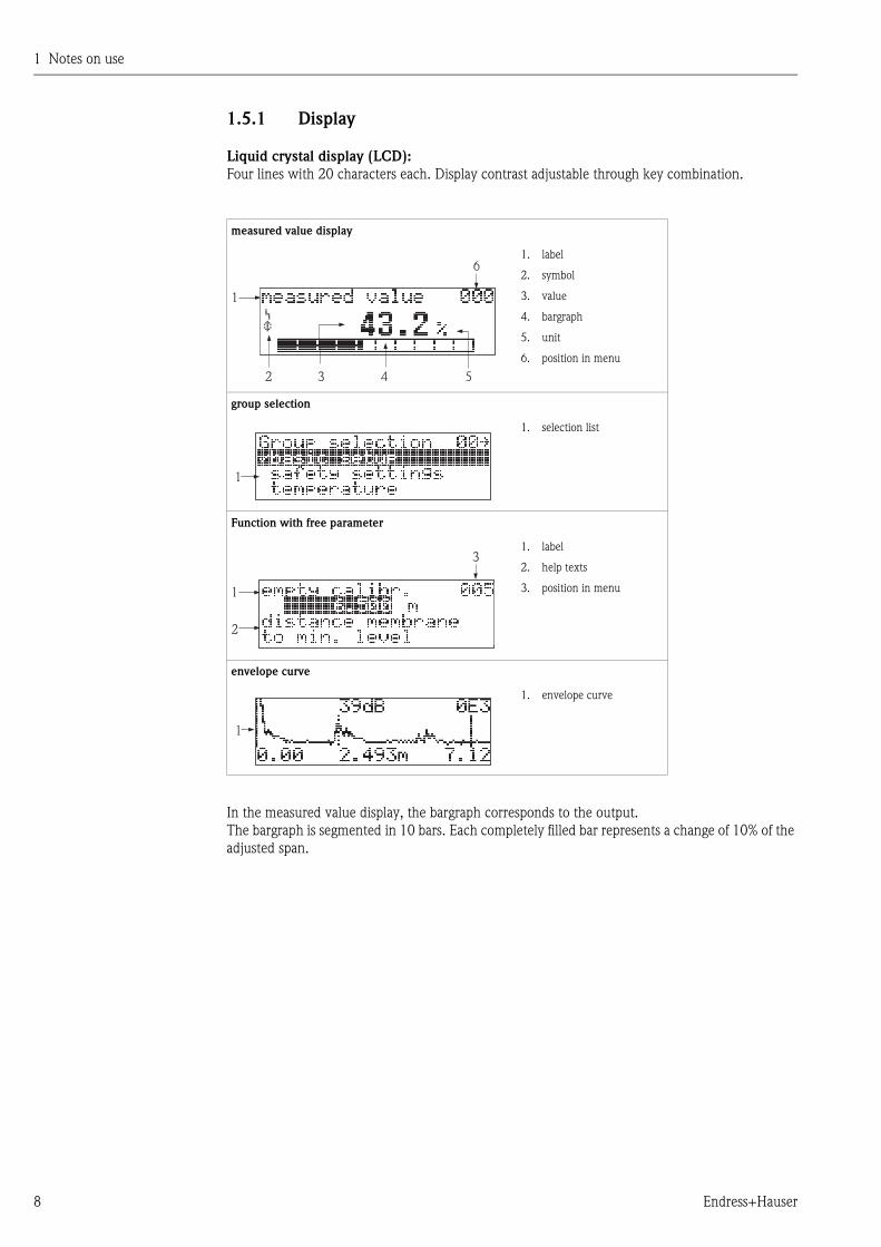
1.5.1 Display
Liquid crystal display (LCD):
Four lines with 20 characters each. Display contrast adjustable through key combination.
In the measured value display, the bargraph corresponds to the output.
The bargraph is segmented in 10 bars. Each completely filled bar represents a change of 10% of the
adjusted span.
measured value display
1. label
2. symbol
3. value
4. bargraph
5. unit
6. position in menu
group selection
1. selection list
Function with free parameter
1. label
2. help texts
3. position in menu
envelope curve
1. envelope curve
4
1
6
3 52
1
2
1
3
1
1 Notes on use
Endress+Hauser 9
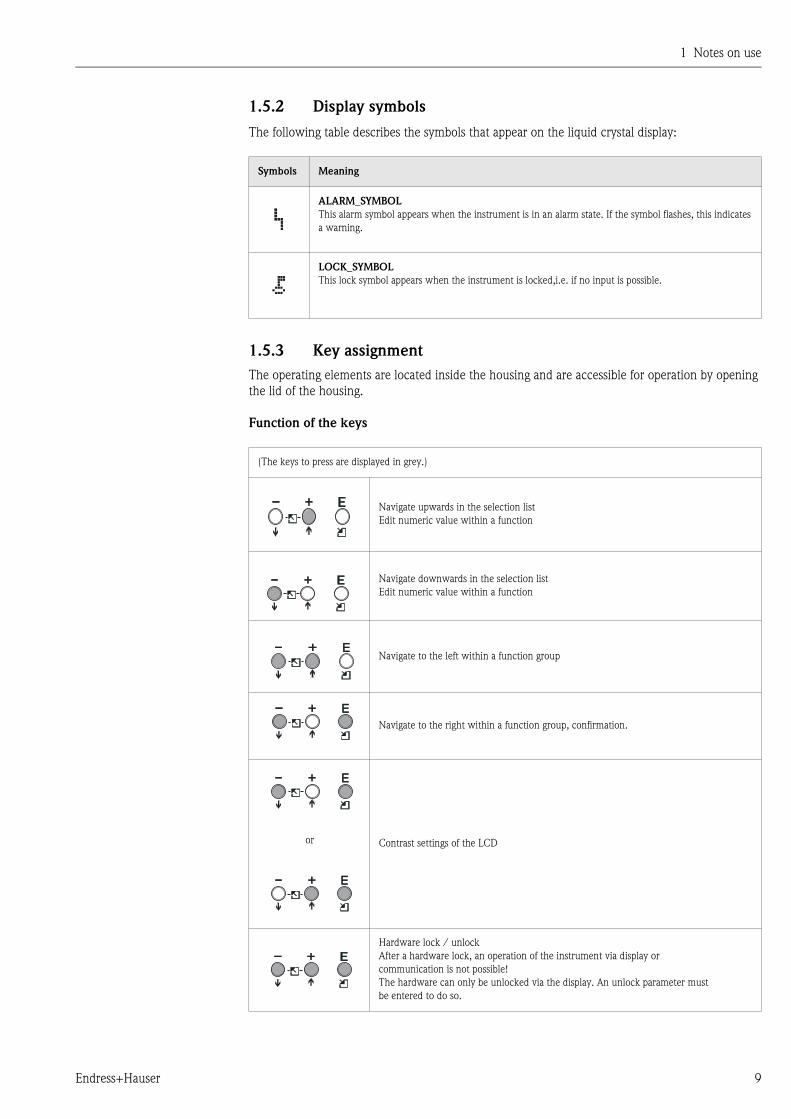
1.5.2 Display symbols
The following table describes the symbols that appear on the liquid crystal display:
1.5.3 Key assignment
The operating elements are located inside the housing and are accessible for operation by opening
the lid of the housing.
Function of the keys
Symbols Meaning
ALARM_SYMBOL
This alarm symbol appears when the instrument is in an alarm state. If the symbol flashes, this indicates
a warning.
LOCK_SYMBOL
This lock symbol appears when the instrument is locked,i.e. if no input is possible.
(The keys to press are displayed in grey.)
Navigate upwards in the selection list
Edit numeric value within a function
Navigate downwards in the selection list
Edit numeric value within a function
Navigate to the left within a function group
Navigate to the right within a function group, confirmation.
or Contrast settings of the LCD
Hardware lock / unlock
After a hardware lock, an operation of the instrument via display or
communication is not possible!
The hardware can only be unlocked via the display. An unlock parameter must
be entered to do so.
1 Notes on use
10 Endress+Hauser
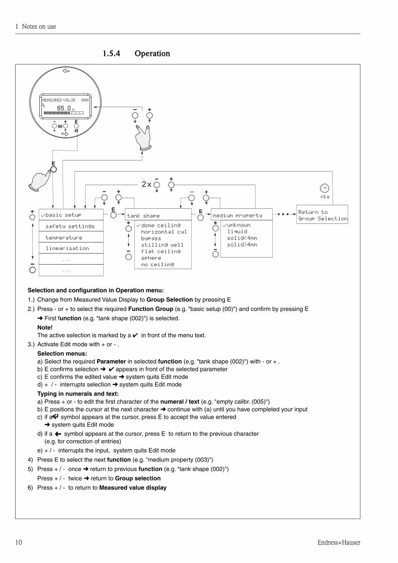
1.5.4 Operation
>3 s
...
2 x
%
������
...
...
�� ����
������
���������
���������
Selection and configuration in Operation menu:
Group Selection
Function Group
unction
Note!
Selection menus:function
Typing in numerals and text:numeral / text
function
function
Group selection
Measured value display
1.) Change from Measured Value Display to by pressing E
2.) Press - or + to select the required (e.g. "basic setup (00)") and confirm by pressing
(e.g. "tank shape (002)") is selected.
The active selection is marked by a in front of the menu text.
3.) Activate Edit mode with or .
a) Select the required in selected (e.g. "tank shape (002)") with or .b) confirms selection appears in front of the selected parameterc) confirms the edited value system quits Edit moded) / interrupts selection system quits Edit mode
a) Press or to edit the first character of the (e.g. "empty calibr. (005)")b) positions the cursor at the next character (a) until you have completed your inputc) if a symbol appears at the cursor, press to accept the value entered
system quits Edit mode
d) if a symbol appears at the cursor, press to return to the previous character(e.g. for correction of entries)
e) / interrupts the input,
4) Press to select the next (e.g. "medium property (003)")
5) Press / once return to previous (e.g. "tank shape (002)")
Press / twice return to
6) Press / to return to
E
First f
+ -
- +EE+ -
+ -E continue with
E
E
+ - system quits Edit mode
E
+ -
+ -
+ -
➜ ✔
➜
➜
➜
➜
➜
➜
➜
✔
Parameter
��������
��������������� !���������
�!"��#�������$�
������!����
����!���!����
�!� ��%!��
�����������$
%���&���!���#�
#�!��
�������$�����
"�!��������$
��%���
���������$
��������������#
➜
1 Notes on use
Endress+Hauser 11
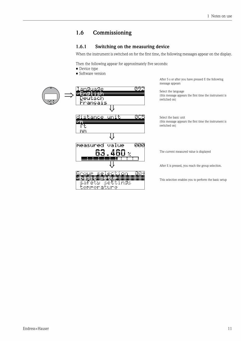
1.6 Commissioning
1.6.1 Switching on the measuring device
When the instrument is switched on for the first time, the following messages appear on the display.
Then the following appear for approximately five seconds:
• Device type
• Software version
After 5 s or after you have pressed E the following
message appears
Select the language
(this message appears the first time the instrument is
switched on)
Select the basic unit
(this message appears the first time the instrument is
switched on)
The current measured value is displayed
After E is pressed, you reach the group selection.
This selection enables you to perform the basic setup

1 Notes on use
12 Endress+Hauser
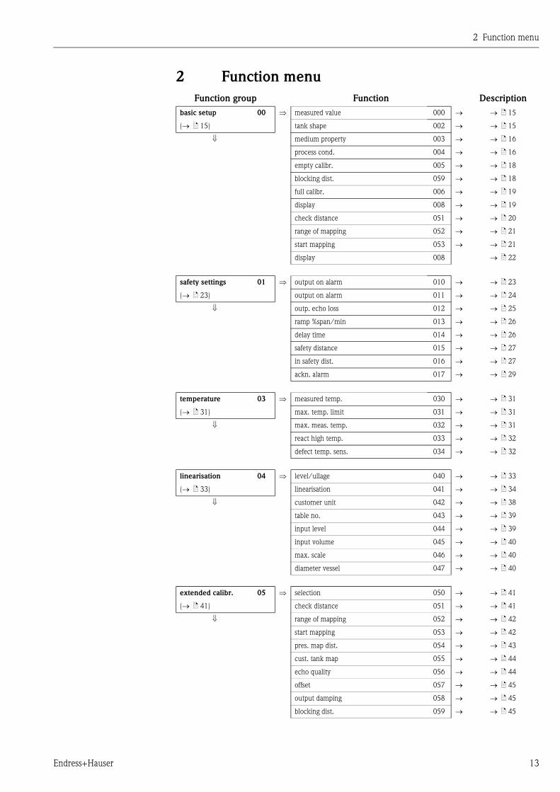
2 Function menu
Endress+Hauser 13
2 Function menu
Function group Function Description
basic setup 00 measured value 000 ä 15
( ä 15) tank shape 002 ä 15
medium property 003 ä 16
process cond. 004 ä 16
empty calibr. 005 ä 18
blocking dist. 059 ä 18
full calibr. 006 ä 19
display 008 ä 19
check distance 051 ä 20
range of mapping 052 ä 21
start mapping 053 ä 21
display 008 ä 22
safety settings 01 output on alarm 010 ä 23
( ä 23) output on alarm 011 ä 24
outp. echo loss 012 ä 25
ramp %span/min 013 ä 26
delay time 014 ä 26
safety distance 015 ä 27
in safety dist. 016 ä 27
ackn. alarm 017 ä 29
temperature 03 measured temp. 030 ä 31
( ä 31) max. temp. limit 031 ä 31
max. meas. temp. 032 ä 31
react high temp. 033 ä 32
defect temp. sens. 034 ä 32
linearisation 04 level/ullage 040 ä 33
( ä 33) linearisation 041 ä 34
customer unit 042 ä 38
table no. 043 ä 39
input level 044 ä 39
input volume 045 ä 40
max. scale 046 ä 40
diameter vessel 047 ä 40
extended calibr. 05 selection 050 ä 41
( ä 41) check distance 051 ä 41
range of mapping 052 ä 42
start mapping 053 ä 42
pres. map dist. 054 ä 43
cust. tank map 055 ä 44
echo quality 056 ä 44
offset 057 ä 45
output damping 058 ä 45
blocking dist. 059 ä 45
2 Function menu
14 Endress+Hauser
Function group Function Description
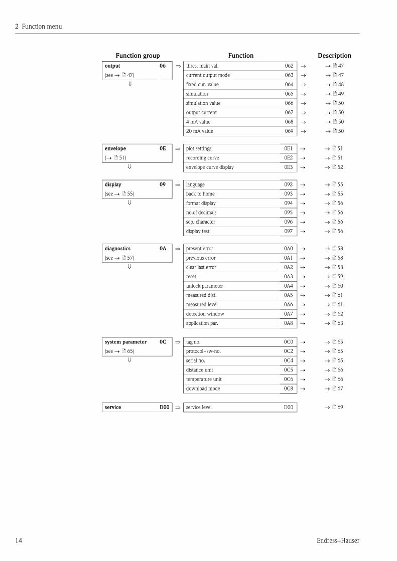
output 06 thres. main val. 062 ä 47
(see ä 47) current output mode 063 ä 47
fixed cur. value 064 ä 48
simulation 065 ä 49
simulation value 066 ä 50
output current 067 ä 50
4 mA value 068 ä 50
20 mA value 069 ä 50
envelope 0E plot settings 0E1 ä 51
( ä 51) recording curve 0E2 ä 51
envelope curve display 0E3 ä 52
display 09 language 092 ä 55
(see ä 55) back to home 093 ä 55
format display 094 ä 56
no.of decimals 095 ä 56
sep. character 096 ä 56
display test 097 ä 56
diagnostics 0A present error 0A0 ä 58
(see ä 57) previous error 0A1 ä 58
clear last error 0A2 ä 58
reset 0A3 ä 59
unlock parameter 0A4 ä 60
measured dist. 0A5 ä 61
measured level 0A6 ä 61
detection window 0A7 ä 62
application par. 0A8 ä 63
system parameter 0C tag no. 0C0 ä 65
(see ä 65) protocol+sw-no. 0C2 ä 65
serial no. 0C4 ä 65
distance unit 0C5 ä 66
temperature unit 0C6 ä 66
download mode 0C8 ä 67
service D00 service level D00 ä 69
3 Function group "basic setup" (00)
Endress+Hauser 15
3 Function group "basic setup" (00)
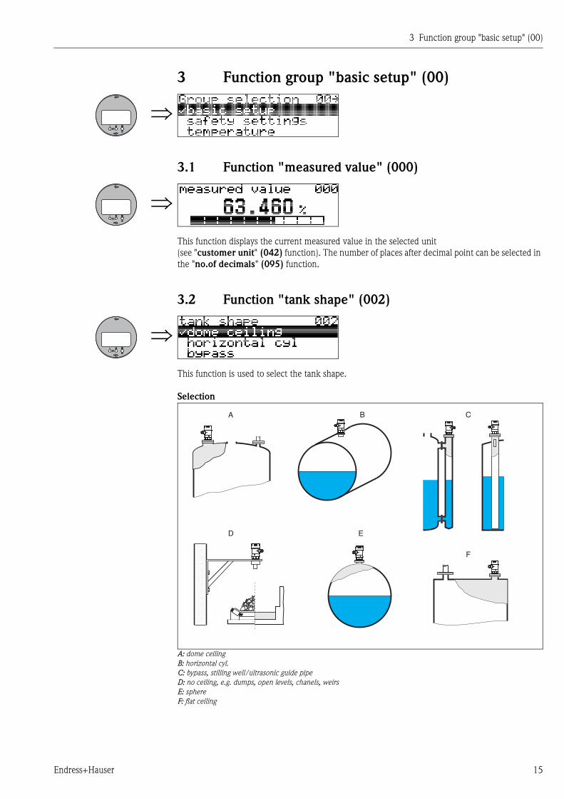
3.1 Function "measured value" (000)
This function displays the current measured value in the selected unit
(see "customer unit" (042) function). The number of places after decimal point can be selected in
the "no.of decimals" (095) function.
3.2 Function "tank shape" (002)
This function is used to select the tank shape.
Selection
A: dome ceilingB: horizontal cyl.C: bypass, stilling well/ultrasonic guide pipeD: no ceiling, e.g. dumps, open levels, chanels, weirsE: sphereF: flat ceiling
A B C
D E
F
3 Function group "basic setup" (00)
16 Endress+Hauser
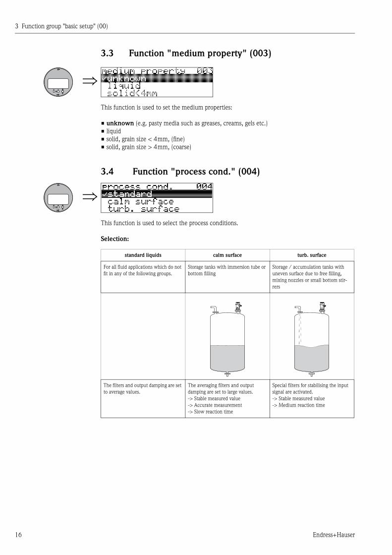
3.3 Function "medium property" (003)
This function is used to set the medium properties:
• unknown (e.g. pasty media such as greases, creams, gels etc.)
• liquid
• solid, grain size < 4mm, (fine)
• solid, grain size > 4mm, (coarse)
3.4 Function "process cond." (004)
This function is used to select the process conditions.
Selection:
standard liquids calm surface turb. surface
For all fluid applications which do not
fit in any of the following groups.
Storage tanks with immersion tube or
bottom filling
Storage / accumulation tanks with
uneven surface due to free filling,
mixing nozzles or small bottom stir-
rers
The filters and output damping are set
to average values.
The averaging filters and output
damping are set to large values.
-> Stable measured value
-> Accurate measurement
-> Slow reaction time
Special filters for stabilising the input
signal are activated.
-> Stable measured value
-> Medium reaction time
3 Function group "basic setup" (00)
Endress+Hauser 17
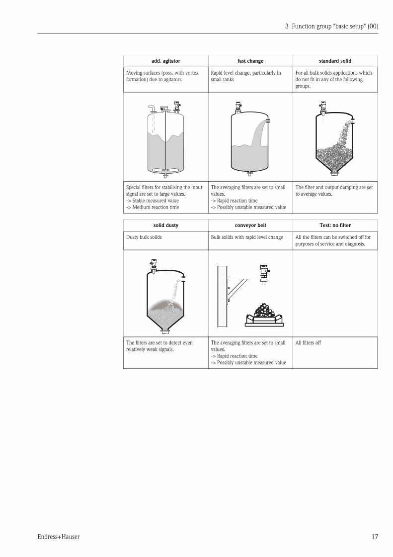
add. agitator fast change standard solid
Moving surfaces (poss. with vortex
formation) due to agitators
Rapid level change, particularly in
small tanks
For all bulk solids applications which
do not fit in any of the following
groups.
Special filters for stabilising the input
signal are set to large values.
-> Stable measured value
-> Medium reaction time
The averaging filters are set to small
values.
-> Rapid reaction time
-> Possibly unstable measured value
The filter and output damping are set
to average values.
solid dusty conveyor belt Test: no filter
Dusty bulk solids Bulk solids with rapid level change All the filters can be switched off for
purposes of service and diagnosis.
The filters are set to detect even
relatively weak signals.
The averaging filters are set to small
values.
-> Rapid reaction time
-> Possibly unstable measured value
All filters off
3 Function group "basic setup" (00)
18 Endress+Hauser
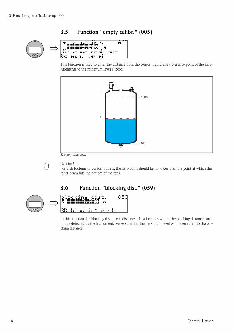
3.5 Function "empty calibr." (005)
This function is used to enter the distance from the sensor membrane (reference point of the mea-
surement) to the minimum level (=zero).
E: empty calibration
" Caution!
For dish bottoms or conical outlets, the zero point should be no lower than the point at which the
radar beam hits the bottom of the tank.
3.6 Function "blocking dist." (059)
In this function the blocking distance is displayed. Level echoes within the blocking distance can
not be detected by the Instrument. Make sure that the maximum level will never run into the blo-
cking distance.
100%
0%
E
3 Function group "basic setup" (00)
Endress+Hauser 19
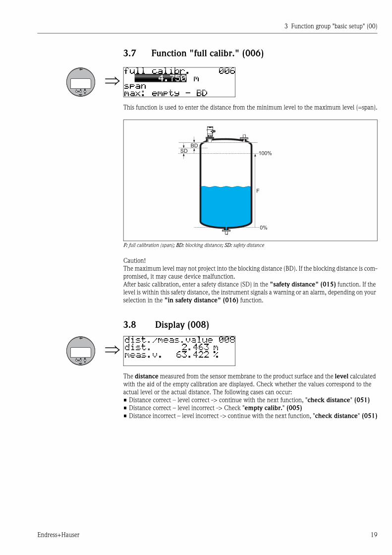
3.7 Function "full calibr." (006)
This function is used to enter the distance from the minimum level to the maximum level (=span).
F: full calibration (span); BD: blocking distance; SD: safety distance
Caution!
The maximum level may not project into the blocking distance (BD). If the blocking distance is com-
promised, it may cause device malfunction.
After basic calibration, enter a safety distance (SD) in the "safety distance" (015) function. If the
level is within this safety distance, the instrument signals a warning or an alarm, depending on your
selection in the "in safety distance" (016) function.
3.8 Display (008)
The distance measured from the sensor membrane to the product surface and the level calculated
with the aid of the empty calibration are displayed. Check whether the values correspond to the
actual level or the actual distance. The following cases can occur:
• Distance correct – level correct -> continue with the next function, "check distance" (051)
• Distance correct – level incorrect -> Check "empty calibr." (005)
• Distance incorrect – level incorrect -> continue with the next function, "check distance" (051)
100%
0%
F
BDSD
3 Function group "basic setup" (00)
20 Endress+Hauser
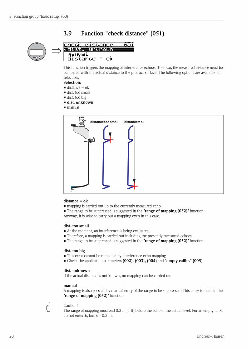
3.9 Function "check distance" (051)
This function triggers the mapping of interference echoes. To do so, the measured distance must be
compared with the actual distance to the product surface. The following options are available for
selection:
Selection:
• distance = ok
• dist. too small
• dist. too big
• dist. unknown
• manual
distance = ok
• mapping is carried out up to the currently measured echo
• The range to be suppressed is suggested in the "range of mapping (052)" function
Anyway, it is wise to carry out a mapping even in this case.
dist. too small
• At the moment, an interference is being evaluated
• Therefore, a mapping is carried out including the presently measured echoes
• The range to be suppressed is suggested in the "range of mapping (052)" function
dist. too big
• This error cannot be remedied by interference echo mapping
• Check the application parameters (002), (003), (004) and "empty calibr." (005)
dist. unknown
If the actual distance is not known, no mapping can be carried out.
manual
A mapping is also possible by manual entry of the range to be suppressed. This entry is made in the
"range of mapping (052)" function.
" Caution!
The range of mapping must end 0.3 m (1 ft) before the echo of the actual level. For an empty tank,
do not enter E, but E – 0.3 m.
+
+
distance toosmall distance =ok
3 Function group "basic setup" (00)
Endress+Hauser 21
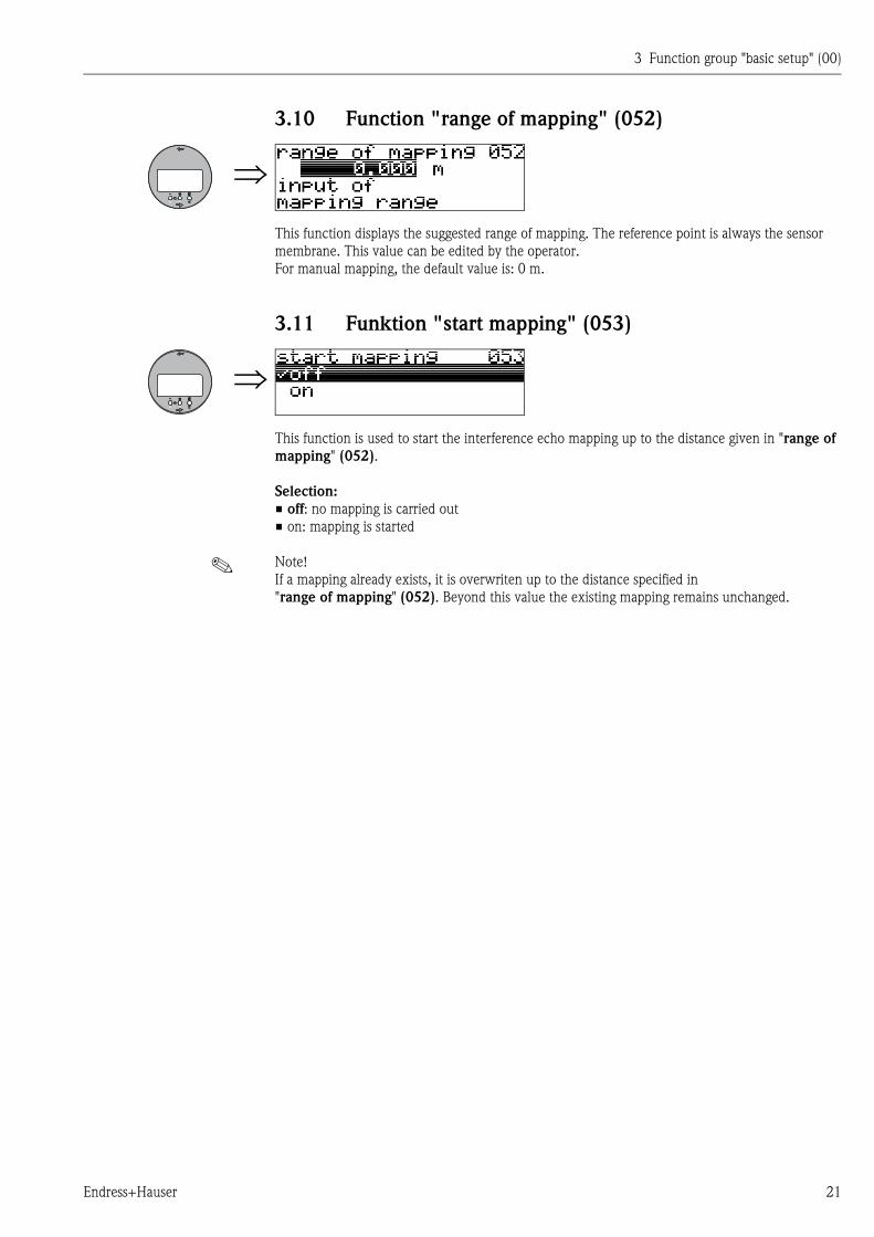
3.10 Function "range of mapping" (052)
This function displays the suggested range of mapping. The reference point is always the sensor
membrane. This value can be edited by the operator.
For manual mapping, the default value is: 0 m.
3.11 Funktion "start mapping" (053)
This function is used to start the interference echo mapping up to the distance given in "range of
mapping" (052).
Selection:
• off: no mapping is carried out
• on: mapping is started
! Note!
If a mapping already exists, it is overwriten up to the distance specified in
"range of mapping" (052). Beyond this value the existing mapping remains unchanged.
3 Function group "basic setup" (00)
22 Endress+Hauser
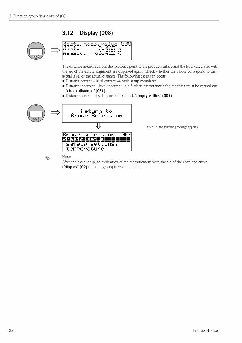
3.12 Display (008)
The distance measured from the reference point to the product surface and the level calculated with
the aid of the empty alignment are displayed again. Check whether the values correspond to the
actual level or the actual distance. The following cases can occur:
• Distance correct – level correct basic setup completed
• Distance incorrect – level incorrect a further interference echo mapping must be carried out
"check distance" (051).
• Distance correct – level incorrect check "empty calibr." (005)
! Note!
After the basic setup, an evaluation of the measurement with the aid of the envelope curve
("display" (09) function group) is recommended.
After 3 s, the following message appears
4 Function group "safety settings" (01)
Endress+Hauser 23
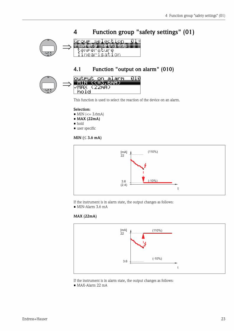
4 Function group "safety settings" (01)
4.1 Function "output on alarm" (010)
This function is used to select the reaction of the device on an alarm.
Selection:
• MIN (<= 3.6mA)
• MAX (22mA)
• hold
• user specific
MIN ( 3.6 mA)
If the instrument is in alarm state, the output changes as follows:
• MIN-Alarm 3.6 mA
MAX (22mA)
If the instrument is in alarm state, the output changes as follows:
• MAX-Alarm 22 mA
(110%)
(-10%)3.6(2.4)
t
[mA]22
(110%)
(-10%)3.6
t
[mA]22
4 Function group "safety settings" (01)
24 Endress+Hauser
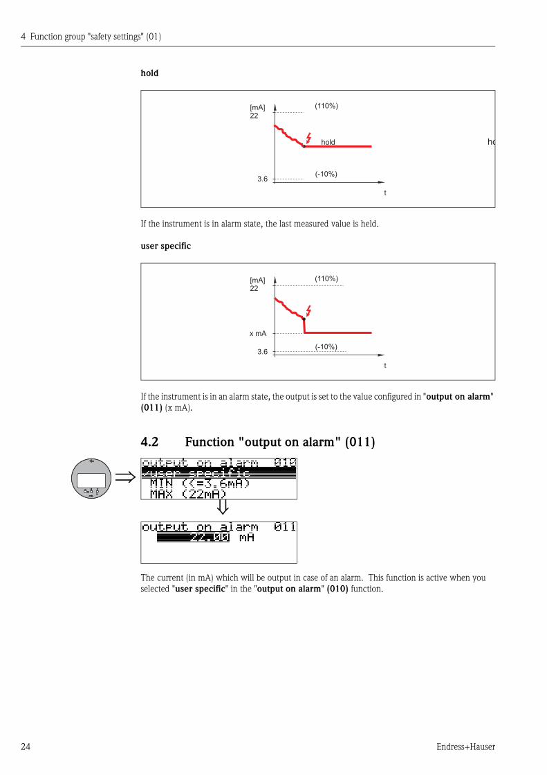
hold
If the instrument is in alarm state, the last measured value is held.
user specific
If the instrument is in an alarm state, the output is set to the value configured in "output on alarm"
(011) (x mA).
4.2 Function "output on alarm" (011)
The current (in mA) which will be output in case of an alarm. This function is active when you
selected "user specific" in the "output on alarm" (010) function.
(110%)
(-10%)3.6
t
[mA]22
hold ho
(110%)
(-10%)3.6
x mA
t
[mA]22
4 Function group "safety settings" (01)
Endress+Hauser 25
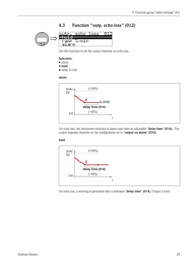
4.3 Function "outp. echo loss" (012)
Use this function to set the output response on echo loss.
Selection:
• alarm
• hold
• ramp %/min
alarm
On echo loss, the instrument switches to alarm state after an adjustable "delay time" (014). The
output response depends on the configuration set in "output on alarm" (010).
hold
On echo loss, a warning is generated after a definable "delay time" (014). Output is held.
4 Function group "safety settings" (01)
26 Endress+Hauser
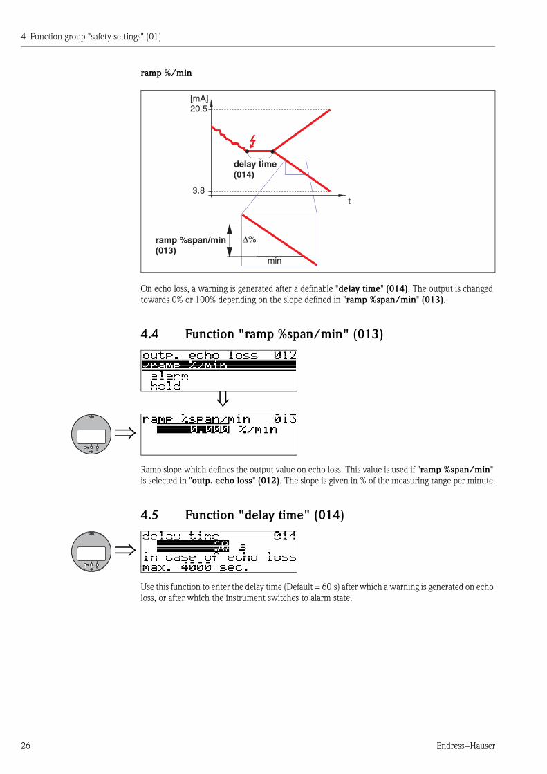
ramp %/min
On echo loss, a warning is generated after a definable "delay time" (014). The output is changed
towards 0% or 100% depending on the slope defined in "ramp %span/min" (013).
4.4 Function "ramp %span/min" (013)
Ramp slope which defines the output value on echo loss. This value is used if "ramp %span/min"
is selected in "outp. echo loss" (012). The slope is given in % of the measuring range per minute.
4.5 Function "delay time" (014)
Use this function to enter the delay time (Default = 60 s) after which a warning is generated on echo
loss, or after which the instrument switches to alarm state.
4 Function group "safety settings" (01)
Endress+Hauser 27
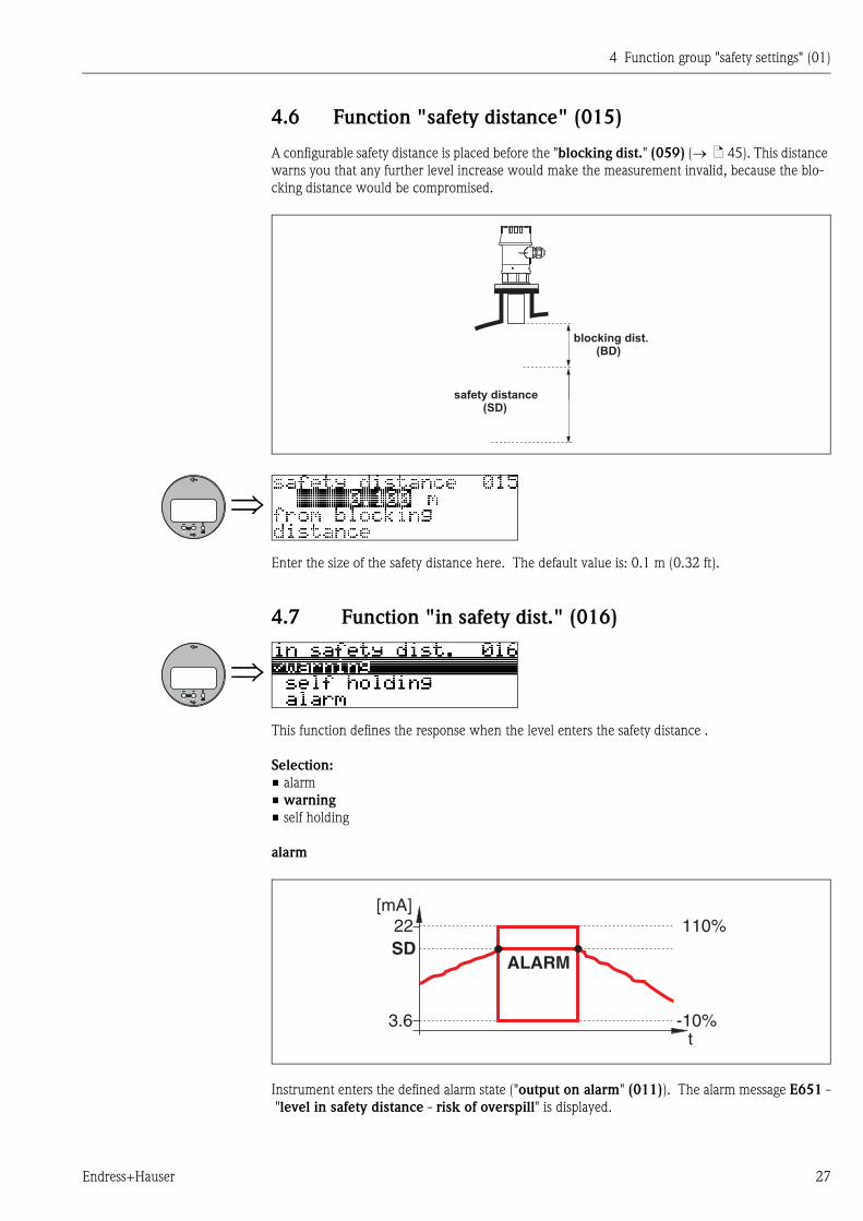
4.6 Function "safety distance" (015)
A configurable safety distance is placed before the "blocking dist." (059) ( ä 45). This distance
warns you that any further level increase would make the measurement invalid, because the blo-
cking distance would be compromised.
Enter the size of the safety distance here. The default value is: 0.1 m (0.32 ft).
4.7 Function "in safety dist." (016)
This function defines the response when the level enters the safety distance .
Selection:
• alarm
• warning
• self holding
alarm
Instrument enters the defined alarm state ("output on alarm" (011)). The alarm message E651 -
"level in safety distance - risk of overspill" is displayed.
safety distance(SD)
blocking dist.(BD)
4 Function group "safety settings" (01)
28 Endress+Hauser
If the level drops out of the safety distance, the alarm warning disappears and the instrument starts
to measure again.
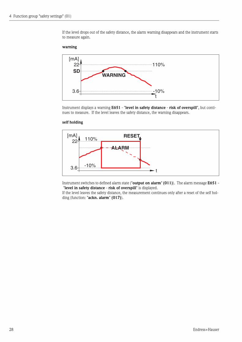
warning
Instrument displays a warning E651 - "level in safety distance - risk of overspill", but conti-
nues to measure. If the level leaves the safety distance, the warning disappears.
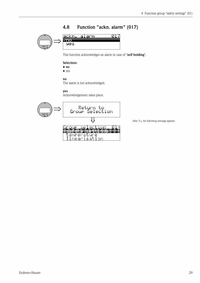
self holding
Instrument switches to defined alarm state ("output on alarm" (011)). The alarm message E651 -
"level in safety distance - risk of overspill" is displayed.
If the level leaves the safety distance, the measurement continues only after a reset of the self hol-
ding (function: "ackn. alarm" (017)).
t
[mA]22SD
110%
3.6 -10%
WARNING
4 Function group "safety settings" (01)
Endress+Hauser 29
4.8 Function "ackn. alarm" (017)
This function acknowledges an alarm in case of "self holding".
Selection:
• no
• yes
no
The alarm is not acknowledged.
yes
Acknowledgement takes place.
After 3 s, the following message appears

4 Function group "safety settings" (01)
30 Endress+Hauser
5 Function group "temperature" (03)
Endress+Hauser 31
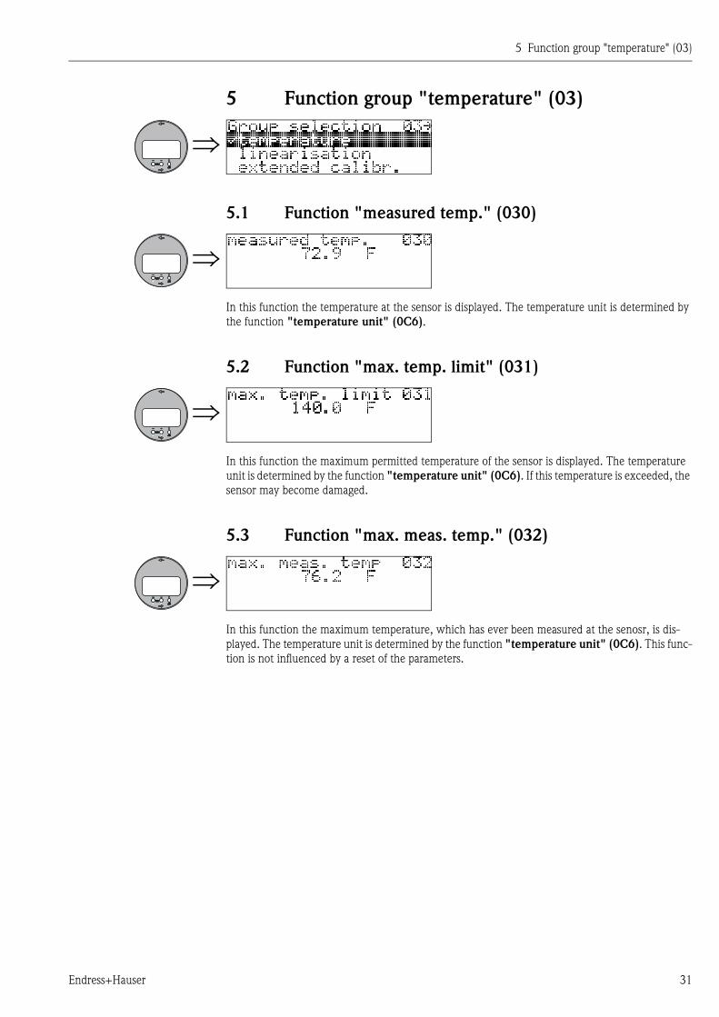
5 Function group "temperature" (03)
5.1 Function "measured temp." (030)
In this function the temperature at the sensor is displayed. The temperature unit is determined by
the function "temperature unit" (0C6).
5.2 Function "max. temp. limit" (031)
In this function the maximum permitted temperature of the sensor is displayed. The temperature
unit is determined by the function "temperature unit" (0C6). If this temperature is exceeded, the
sensor may become damaged.
5.3 Function "max. meas. temp." (032)
In this function the maximum temperature, which has ever been measured at the senosr, is dis-
played. The temperature unit is determined by the function "temperature unit" (0C6). This func-
tion is not influenced by a reset of the parameters.
5 Function group "temperature" (03)
32 Endress+Hauser
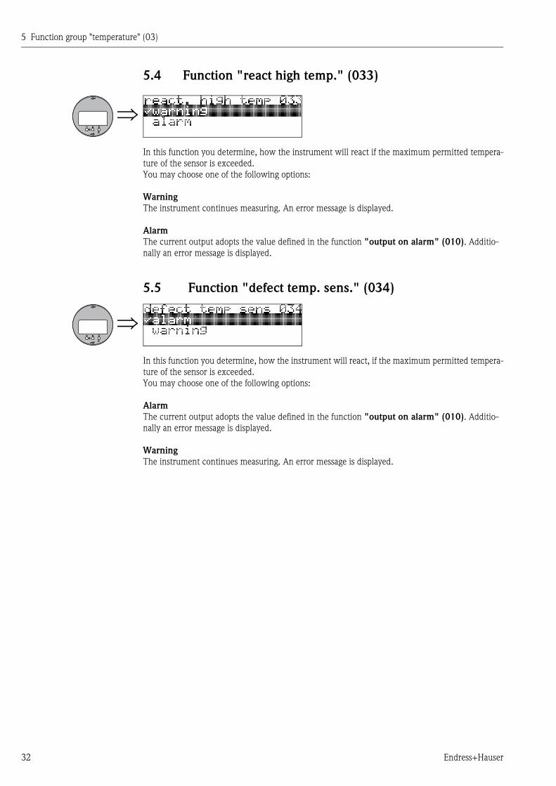
5.4 Function "react high temp." (033)
In this function you determine, how the instrument will react if the maximum permitted tempera-
ture of the sensor is exceeded.
You may choose one of the following options:
Warning
The instrument continues measuring. An error message is displayed.
Alarm
The current output adopts the value defined in the function "output on alarm" (010). Additio-
nally an error message is displayed.
5.5 Function "defect temp. sens." (034)
In this function you determine, how the instrument will react, if the maximum permitted tempera-
ture of the sensor is exceeded.
You may choose one of the following options:
Alarm
The current output adopts the value defined in the function "output on alarm" (010). Additio-
nally an error message is displayed.
Warning
The instrument continues measuring. An error message is displayed.
6 Function group "linearisation" (04)
Endress+Hauser 33
6 Function group "linearisation" (04)
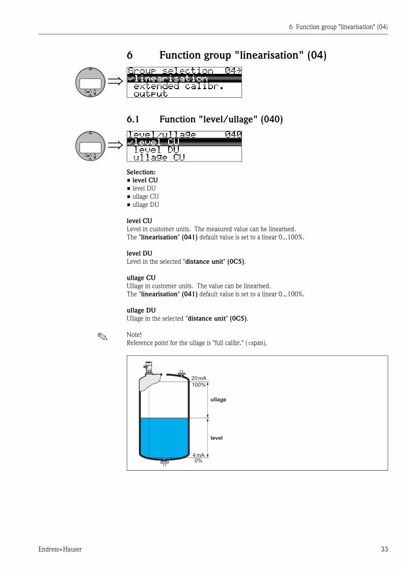
6.1 Function "level/ullage" (040)
Selection:
• level CU
• level DU
• ullage CU
• ullage DU
level CU
Level in customer units. The measured value can be linearised.
The "linearisation" (041) default value is set to a linear 0...100%.
level DU
Level in the selected "distance unit" (0C5).
ullage CU
Ullage in customer units. The value can be linearised.
The "linearisation" (041) default value is set to a linear 0...100%.
ullage DU
Ullage in the selected "distance unit" (0C5).
! Note!
Reference point for the ullage is "full calibr." (=span).
20 mA
100%
4 mA0%
level
ullage
6 Function group "linearisation" (04)
34 Endress+Hauser
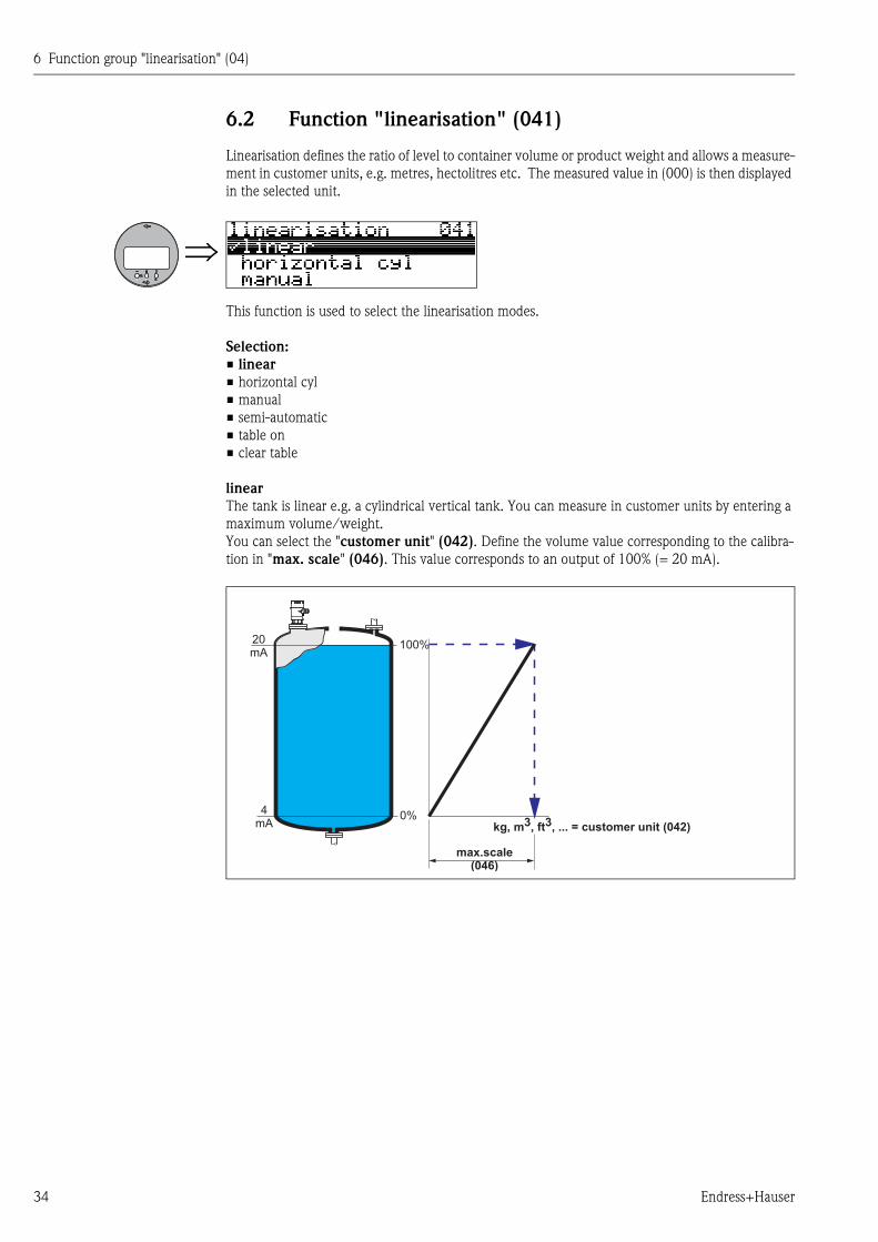
6.2 Function "linearisation" (041)
Linearisation defines the ratio of level to container volume or product weight and allows a measure-
ment in customer units, e.g. metres, hectolitres etc. The measured value in (000) is then displayed
in the selected unit.
This function is used to select the linearisation modes.
Selection:
• linear
• horizontal cyl
• manual
• semi-automatic
• table on
• clear table
linear
The tank is linear e.g. a cylindrical vertical tank. You can measure in customer units by entering a
maximum volume/weight.
You can select the "customer unit" (042). Define the volume value corresponding to the calibra-
tion in "max. scale" (046). This value corresponds to an output of 100% (= 20 mA).
100%20mA
0%4mA kg, m3, ft3, ... = customer unit (042)
max.scale(046)
6 Function group "linearisation" (04)
Endress+Hauser 35
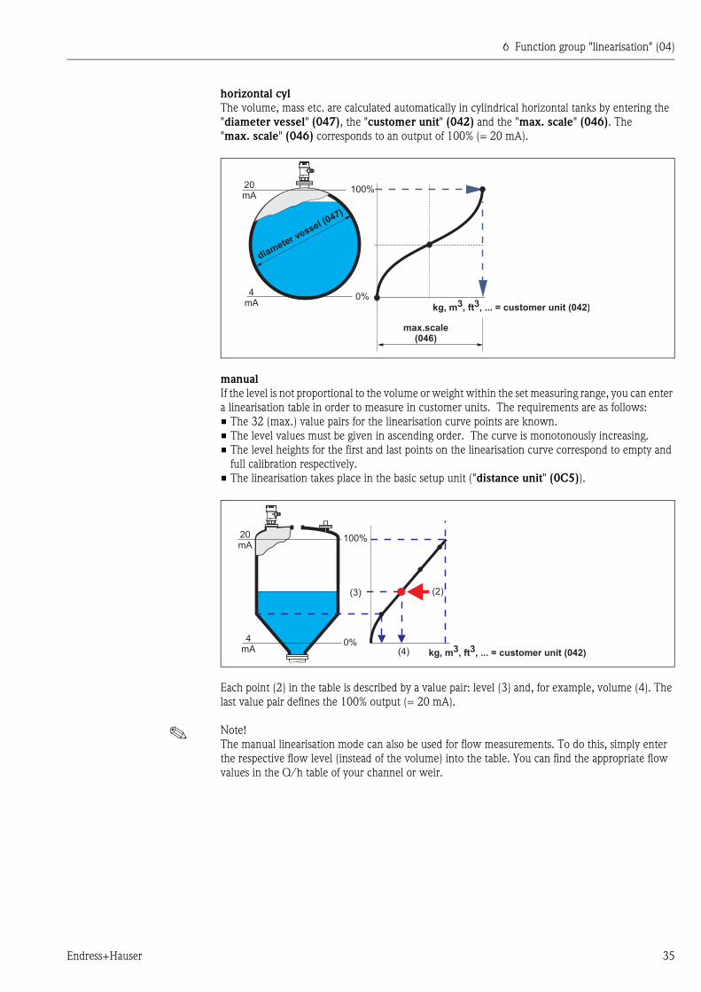
horizontal cyl
The volume, mass etc. are calculated automatically in cylindrical horizontal tanks by entering the
"diameter vessel" (047), the "customer unit" (042) and the "max. scale" (046). The
"max. scale" (046) corresponds to an output of 100% (= 20 mA).
manual
If the level is not proportional to the volume or weight within the set measuring range, you can enter
a linearisation table in order to measure in customer units. The requirements are as follows:
• The 32 (max.) value pairs for the linearisation curve points are known.
• The level values must be given in ascending order. The curve is monotonously increasing.
• The level heights for the first and last points on the linearisation curve correspond to empty and
full calibration respectively.
• The linearisation takes place in the basic setup unit ("distance unit" (0C5)).
Each point (2) in the table is described by a value pair: level (3) and, for example, volume (4). The
last value pair defines the 100% output (= 20 mA).
! Note!
The manual linearisation mode can also be used for flow measurements. To do this, simply enter
the respective flow level (instead of the volume) into the table. You can find the appropriate flow
values in the Q/h table of your channel or weir.
100%20mA
0%4mA
kg, m3, ft3, ... = customer unit (042)
max.scale(046)
diameter vessel (047)
100%20mA
0%4mA
(2)
(4)
(3)
kg, m3, ft3, ... = customer unit (042)
6 Function group "linearisation" (04)
36 Endress+Hauser
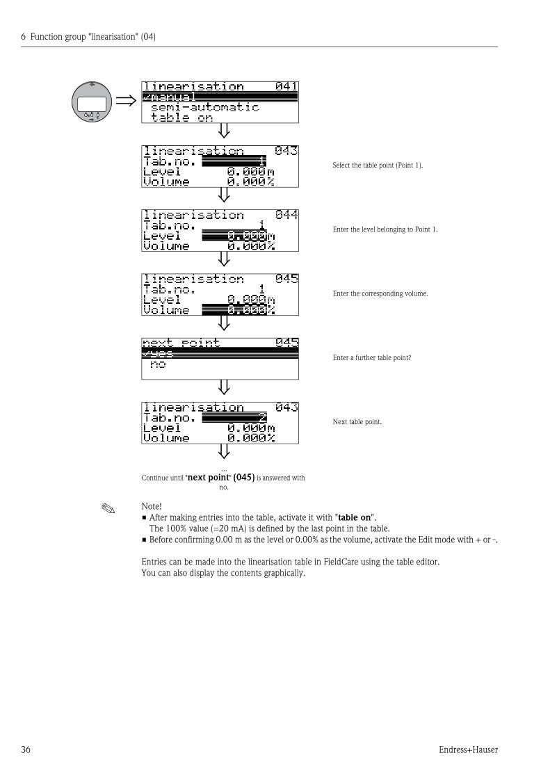
! Note!
• After making entries into the table, activate it with "table on".
The 100% value (=20 mA) is defined by the last point in the table.
• Before confirming 0.00 m as the level or 0.00% as the volume, activate the Edit mode with + or -.
Entries can be made into the linearisation table in FieldCare using the table editor.
You can also display the contents graphically.
Select the table point (Point 1).
Enter the level belonging to Point 1.
Enter the corresponding volume.
Enter a further table point?
Next table point.
...
Continue until "next point" (045) is answered with
no.
6 Function group "linearisation" (04)
Endress+Hauser 37
semi-automatic
The tank is filled in stages when the linearisation curve is entered semi-automatically. The instru-
ment automatically detects the level and the corresponding volume/weight has to be entered.
The procedure is similar to manual table entry, where the level value for each table point is given
automatically by the instrument.
! Note!
If the tank is emptied (out litres), pay attention to the following points:
• The number of points must be known in advance.
• The first table number = (32 - number of points).
• Entries in "Tab. no." (043) are made in reverse order (last entry = 1).
table on
An entered linearisation table only becomes effective when activated.
clear table
Before making entries into the linearisation table, any existing tables must be deleted. The lineari-
sation mode automatically switches to linear.
! Note!
A linearisation table can be deactivated by selecting "linear" or "horizontal cyl" (or the "level/
ullage" (040) function = "level DU", "ullage DU"). It is not deleted and can be reactivated at any
time by selecting "table on".
6 Function group "linearisation" (04)
38 Endress+Hauser
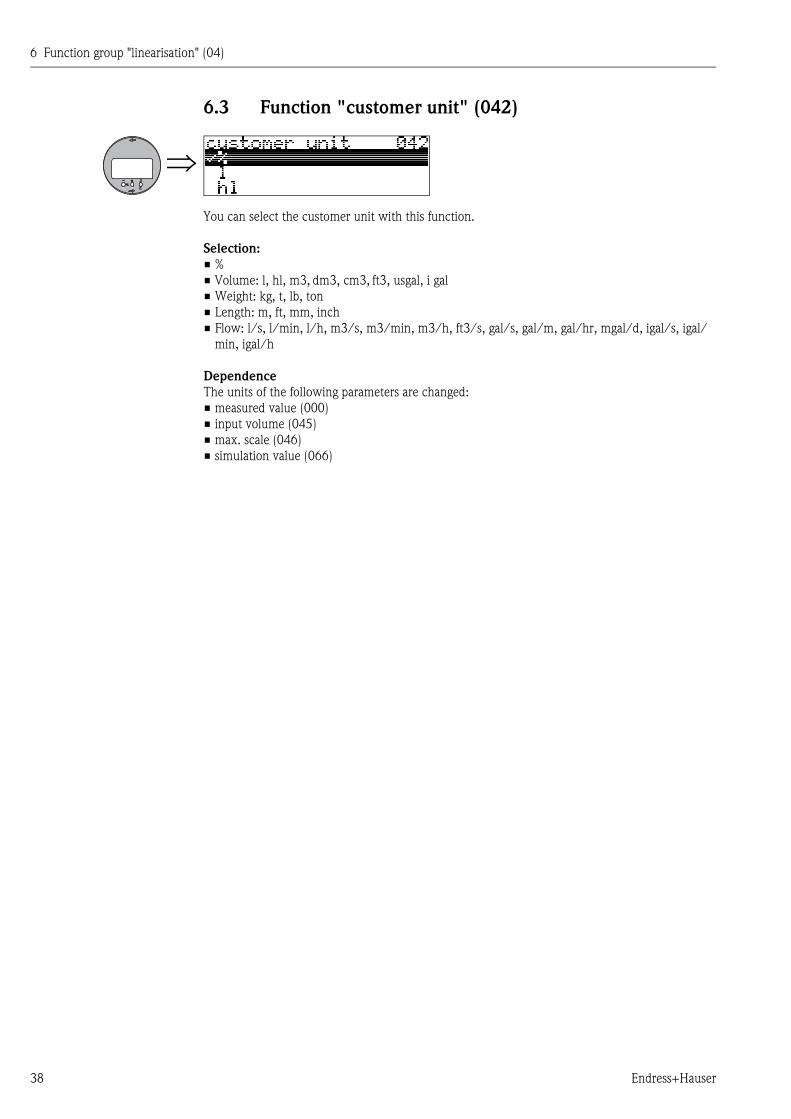
6.3 Function "customer unit" (042)
You can select the customer unit with this function.
Selection:
• %
• Volume: l, hl, m3, dm3, cm3, ft3, usgal, i gal
• Weight: kg, t, lb, ton
• Length: m, ft, mm, inch
• Flow: l/s, l/min, l/h, m3/s, m3/min, m3/h, ft3/s, gal/s, gal/m, gal/hr, mgal/d, igal/s, igal/
min, igal/h
Dependence
The units of the following parameters are changed:
• measured value (000)
• input volume (045)
• max. scale (046)
• simulation value (066)
6 Function group "linearisation" (04)
Endress+Hauser 39
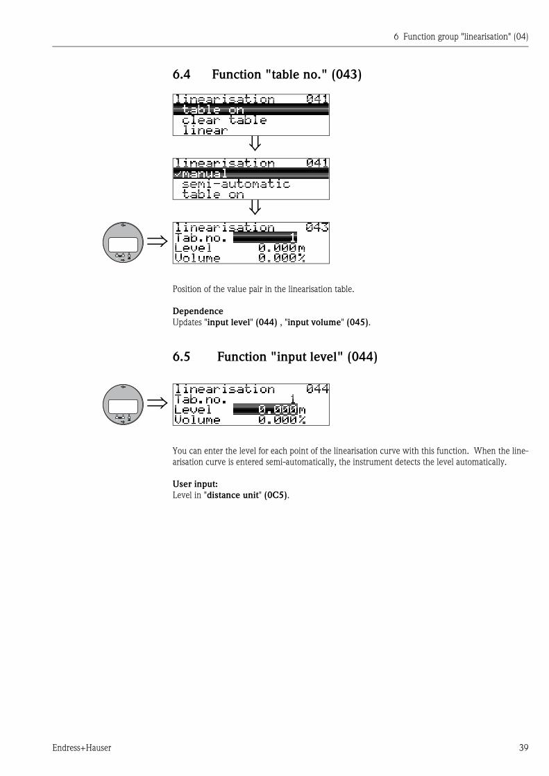
6.4 Function "table no." (043)
Position of the value pair in the linearisation table.
Dependence
Updates "input level" (044) , "input volume" (045).
6.5 Function "input level" (044)
You can enter the level for each point of the linearisation curve with this function. When the line-
arisation curve is entered semi-automatically, the instrument detects the level automatically.
User input:
Level in "distance unit" (0C5).
6 Function group "linearisation" (04)
40 Endress+Hauser
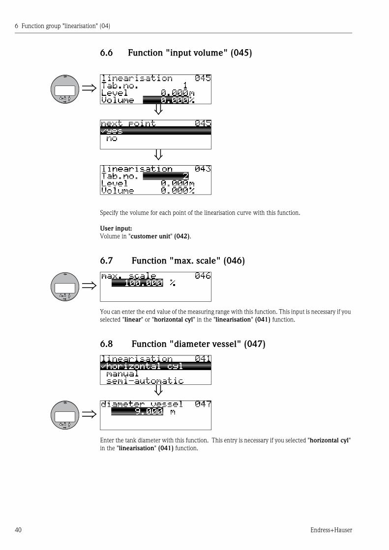
6.6 Function "input volume" (045)
Specify the volume for each point of the linearisation curve with this function.
User input:
Volume in "customer unit" (042).
6.7 Function "max. scale" (046)
You can enter the end value of the measuring range with this function. This input is necessary if you
selected "linear" or "horizontal cyl" in the "linearisation" (041) function.
6.8 Function "diameter vessel" (047)
Enter the tank diameter with this function. This entry is necessary if you selected "horizontal cyl"
in the "linearisation" (041) function.
7 Function group "extended calibr." (05)
Endress+Hauser 41
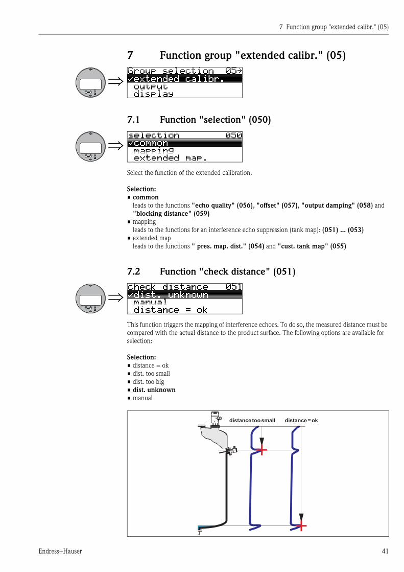
7 Function group "extended calibr." (05)
7.1 Function "selection" (050)
Select the function of the extended calibration.
Selection:
• common
leads to the functions "echo quality" (056), "offset" (057), "output damping" (058) and
"blocking distance" (059)
• mapping
leads to the functions for an interference echo suppression (tank map): (051) ... (053)
• extended map
leads to the functions " pres. map. dist." (054) and "cust. tank map" (055)
7.2 Function "check distance" (051)
This function triggers the mapping of interference echoes. To do so, the measured distance must be
compared with the actual distance to the product surface. The following options are available for
selection:
Selection:
• distance = ok
• dist. too small
• dist. too big
• dist. unknown
• manual
+
+
distance toosmall distance =ok
7 Function group "extended calibr." (05)
42 Endress+Hauser
distance = ok
• mapping is carried out up to the currently measured echo
• The range to be suppressed is suggested in the "range of mapping (052)" function
Anyway, it is wise to carry out a mapping even in this case.
dist. too small
• At the moment, an interference is being evaluated
• Therefore, a mapping is carried out including the presently measured echoes
• The range to be suppressed is suggested in the "range of mapping (052)" function
dist. too big
• This error cannot be remedied by interference echo mapping
• Check the application parameters (002), (003), (004) and "empty calibr." (005)
dist. unknown
If the actual distance is not known, no mapping can be carried out.
manual
A mapping is also possible by manual entry of the range to be suppressed. This entry is made in the
"range of mapping (052)" function.
" Caution!
The range of mapping must end 0.3 m (1 ft) before the echo of the actual level. For an empty tank,
do not enter E, but E – 0.3 m.
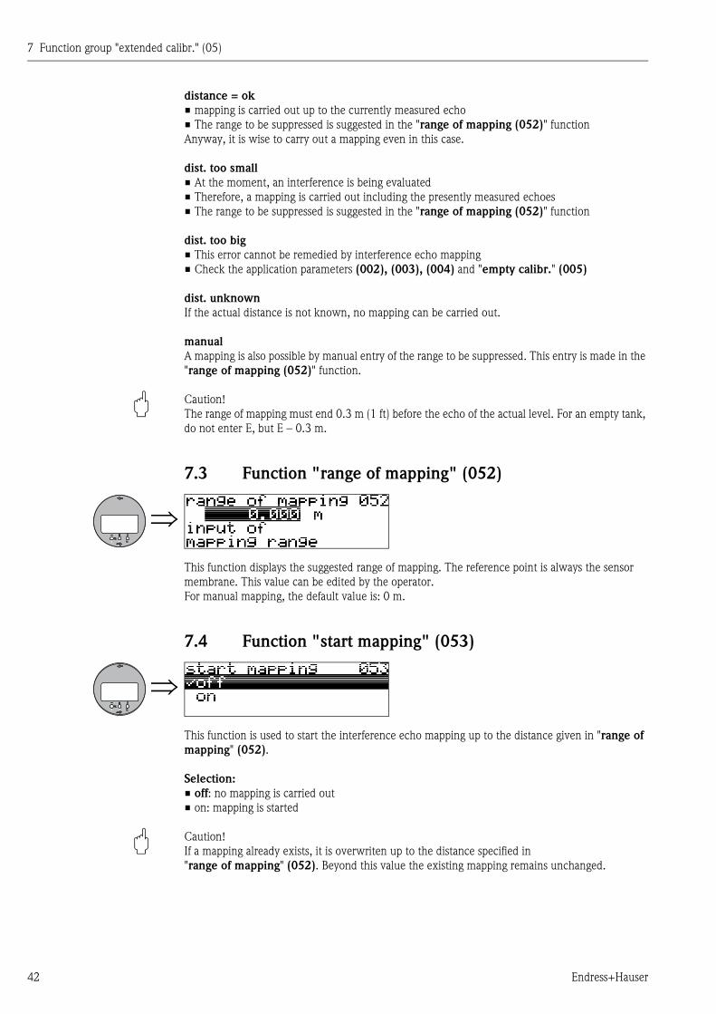
7.3 Function "range of mapping" (052)
This function displays the suggested range of mapping. The reference point is always the sensor
membrane. This value can be edited by the operator.
For manual mapping, the default value is: 0 m.
7.4 Function "start mapping" (053)
This function is used to start the interference echo mapping up to the distance given in "range of
mapping" (052).
Selection:
• off: no mapping is carried out
• on: mapping is started
" Caution!
If a mapping already exists, it is overwriten up to the distance specified in
"range of mapping" (052). Beyond this value the existing mapping remains unchanged.
7 Function group "extended calibr." (05)
Endress+Hauser 43
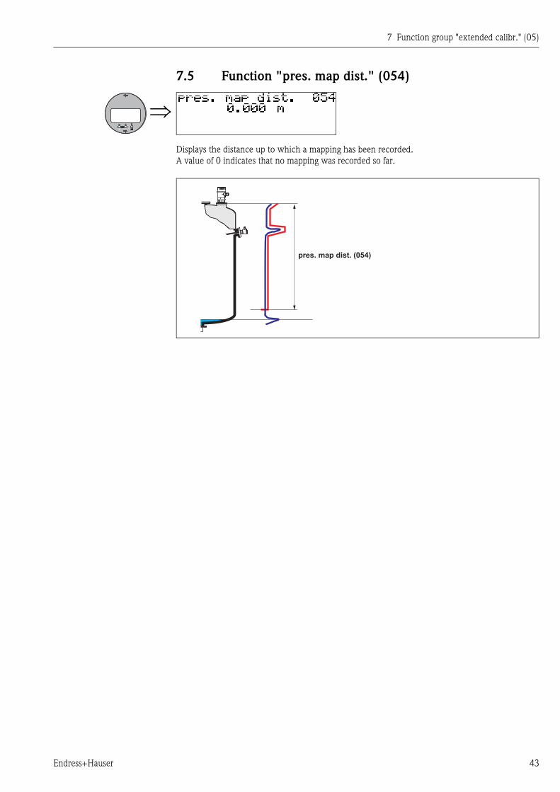
7.5 Function "pres. map dist." (054)
Displays the distance up to which a mapping has been recorded.
A value of 0 indicates that no mapping was recorded so far.
pres. map dist. (054)
7 Function group "extended calibr." (05)
44 Endress+Hauser
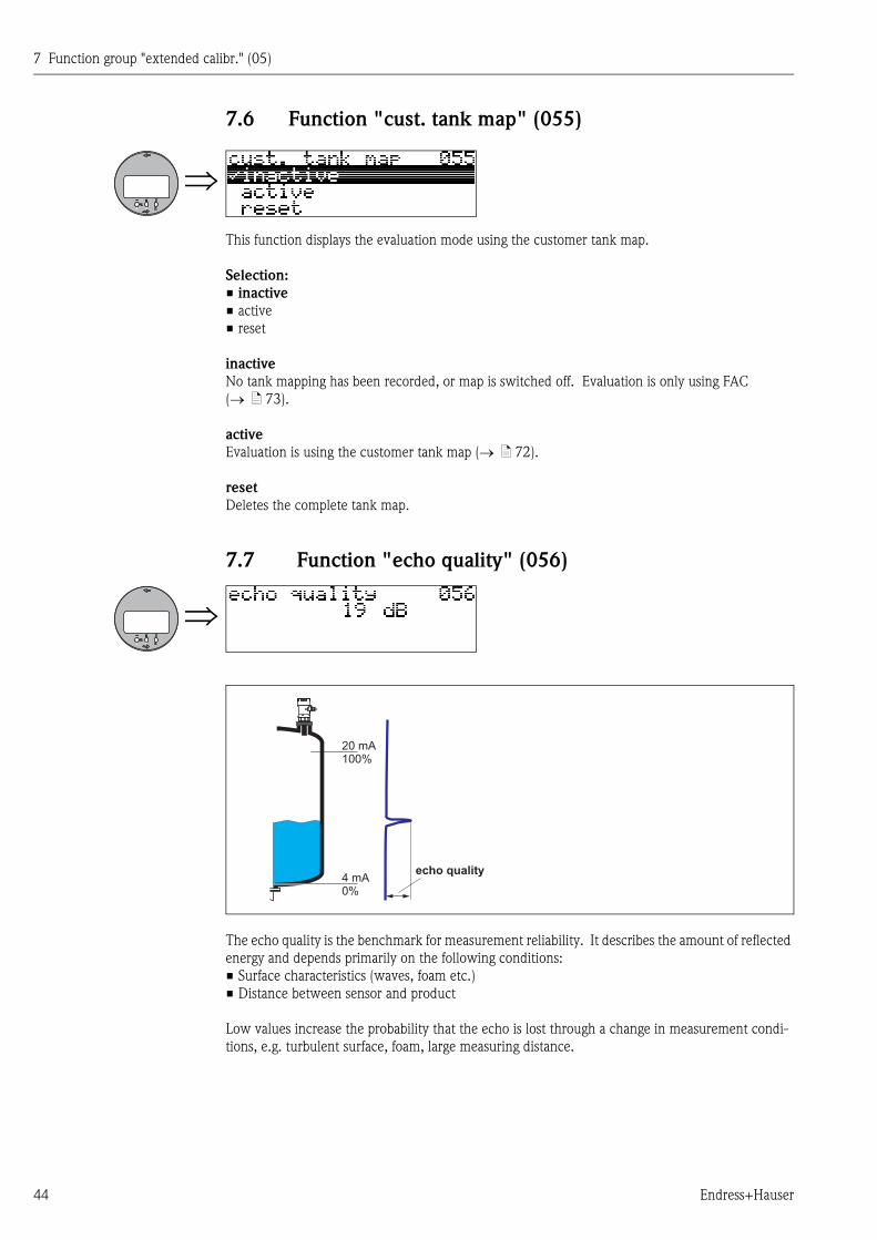
7.6 Function "cust. tank map" (055)
This function displays the evaluation mode using the customer tank map.
Selection:
• inactive
• active
• reset
inactive
No tank mapping has been recorded, or map is switched off. Evaluation is only using FAC
( ä 73).
active
Evaluation is using the customer tank map ( ä 72).
reset
Deletes the complete tank map.
7.7 Function "echo quality" (056)
The echo quality is the benchmark for measurement reliability. It describes the amount of reflected
energy and depends primarily on the following conditions:
• Surface characteristics (waves, foam etc.)
• Distance between sensor and product
Low values increase the probability that the echo is lost through a change in measurement condi-
tions, e.g. turbulent surface, foam, large measuring distance.
20 mA100%
4 mA0%
echo quality
7 Function group "extended calibr." (05)
Endress+Hauser 45
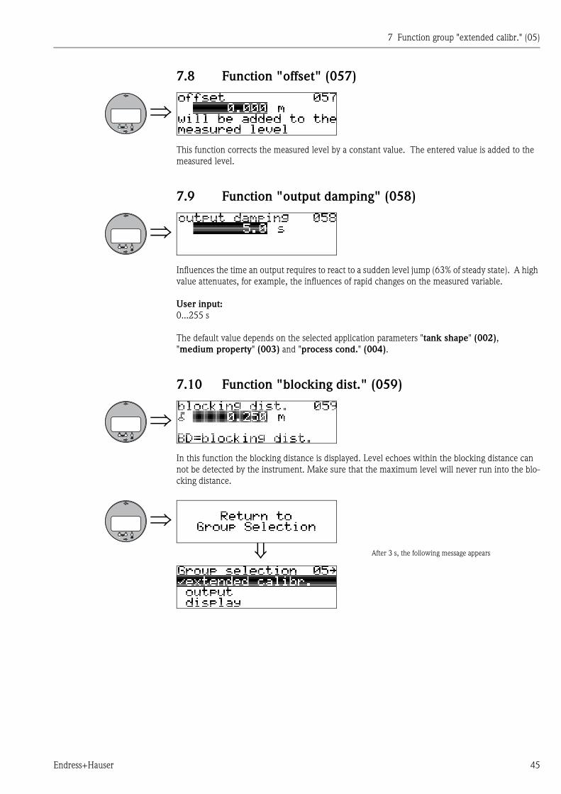
7.8 Function "offset" (057)
This function corrects the measured level by a constant value. The entered value is added to the
measured level.
7.9 Function "output damping" (058)
Influences the time an output requires to react to a sudden level jump (63% of steady state). A high
value attenuates, for example, the influences of rapid changes on the measured variable.
User input:
0...255 s
The default value depends on the selected application parameters "tank shape" (002),
"medium property" (003) and "process cond." (004).
7.10 Function "blocking dist." (059)
In this function the blocking distance is displayed. Level echoes within the blocking distance can
not be detected by the instrument. Make sure that the maximum level will never run into the blo-
cking distance.
After 3 s, the following message appears

7 Function group "extended calibr." (05)
46 Endress+Hauser
8 Function group "output" (06)
Endress+Hauser 47
8 Function group "output" (06)
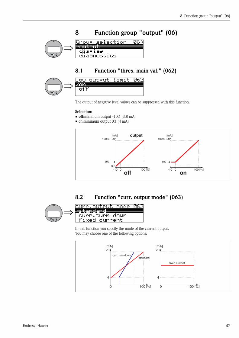
8.1 Function "thres. main val." (062)
The output of negative level values can be suppressed with this function.
Selection:
• off:minimum output -10% (3.8 mA)
• on:minimum output 0% (4 mA)
8.2 Function "curr. output mode" (063)
In this function you specify the mode of the current output.
You may choose one of the following options:
[mA]20
[mA]20
4
100 [%]0
4
100 [%]0
curr. turn down
fixed current
standard
8 Function group "output" (06)
48 Endress+Hauser
standard
The total measuring range (0 ... 100%) will be mapped to the current intervall
(4 ... 20 mA).
curr. turn down
Only a part of the measuring range will be mapped to the current intervall
(4 ... 20 mA).
Use the functions "4-mA-value" (068) and "20-mA-value" (069) to define the concerning
range.
fixed current
The current is fixed. The value of the current is defined in the "fixed current" (064) function.
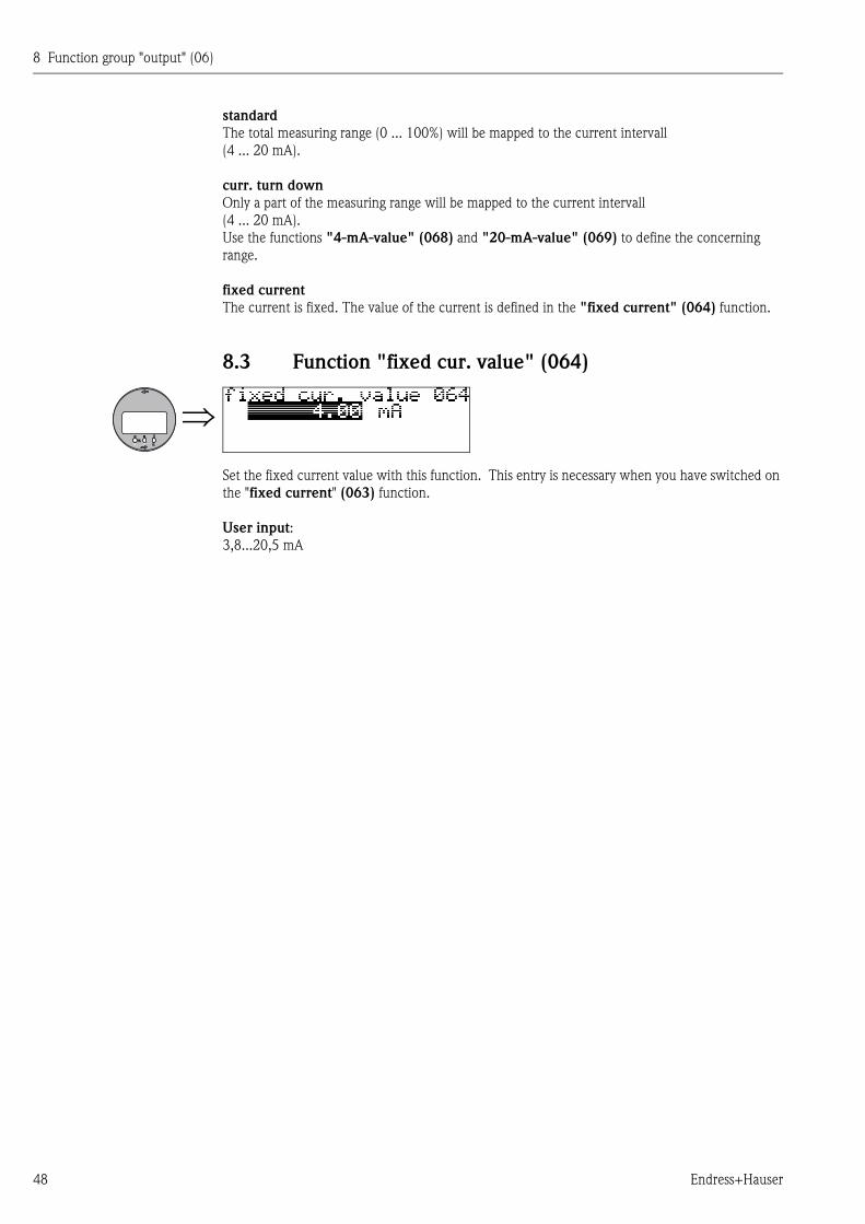
8.3 Function "fixed cur. value" (064)
Set the fixed current value with this function. This entry is necessary when you have switched on
the "fixed current" (063) function.
User input:
3,8...20,5 mA
8 Function group "output" (06)
Endress+Hauser 49
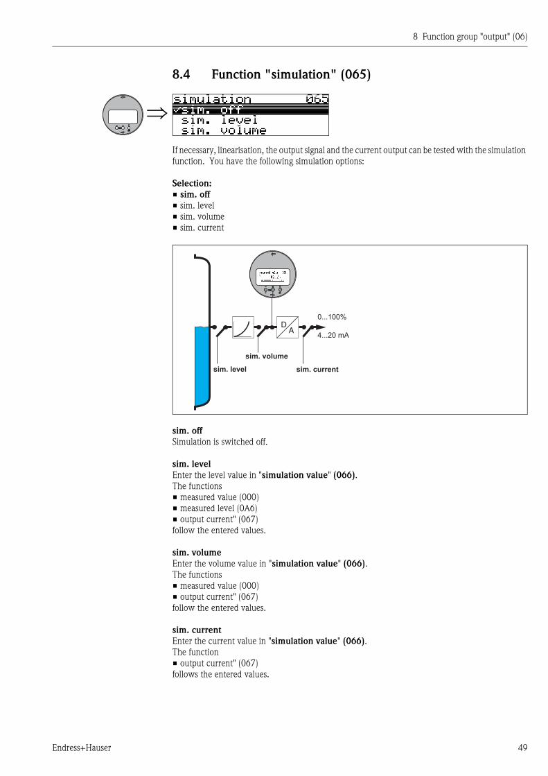
8.4 Function "simulation" (065)
If necessary, linearisation, the output signal and the current output can be tested with the simulation
function. You have the following simulation options:
Selection:
• sim. off
• sim. level
• sim. volume
• sim. current
sim. off
Simulation is switched off.
sim. level
Enter the level value in "simulation value" (066).
The functions
• measured value (000)
• measured level (0A6)
• output current" (067)
follow the entered values.
sim. volume
Enter the volume value in "simulation value" (066).
The functions
• measured value (000)
• output current" (067)
follow the entered values.
sim. current
Enter the current value in "simulation value" (066).
The function
• output current" (067)
follows the entered values.
DA
4...20 mA
0...100%
sim. level
sim. volume
sim. current
8 Function group "output" (06)
50 Endress+Hauser
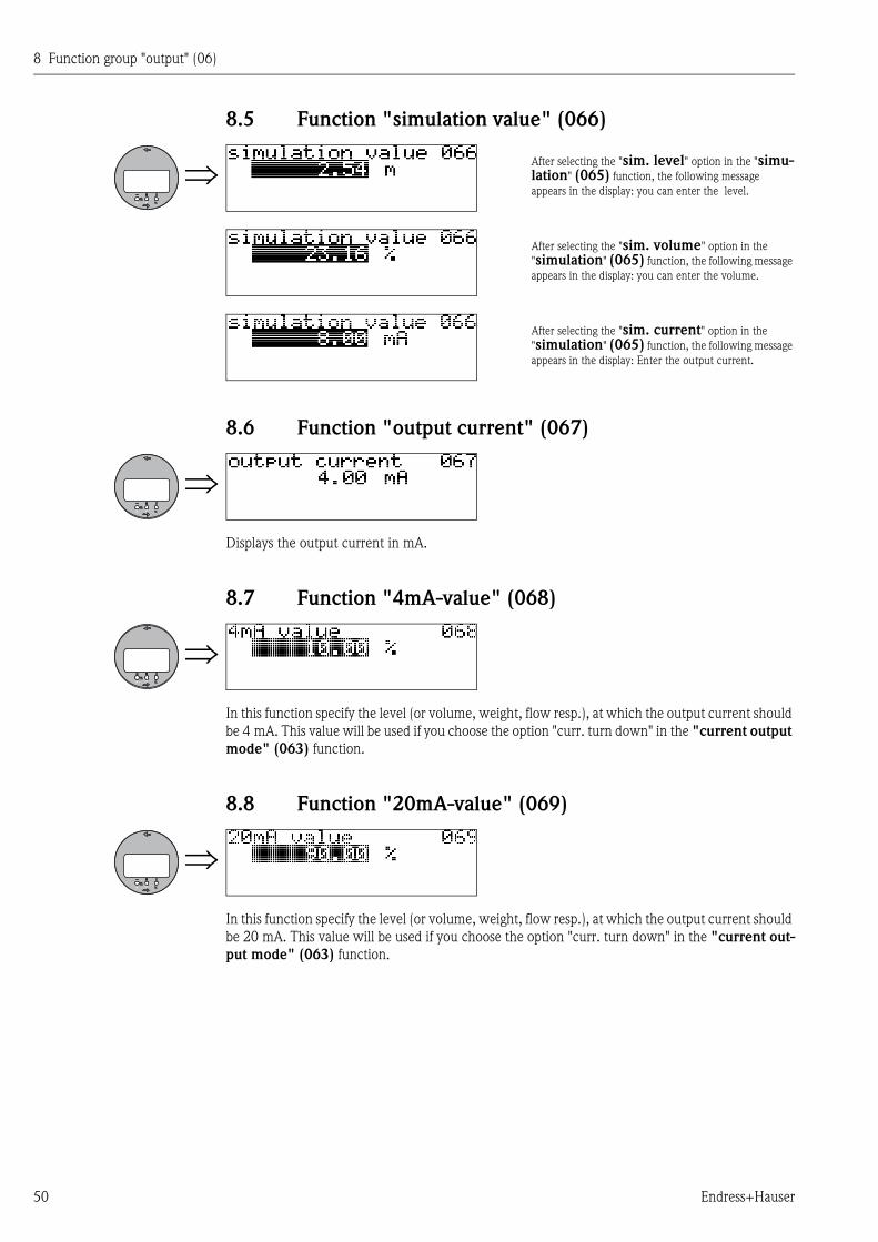
8.5 Function "simulation value" (066)
8.6 Function "output current" (067)
Displays the output current in mA.
8.7 Function "4mA-value" (068)
In this function specify the level (or volume, weight, flow resp.), at which the output current should
be 4 mA. This value will be used if you choose the option "curr. turn down" in the "current output
mode" (063) function.
8.8 Function "20mA-value" (069)
In this function specify the level (or volume, weight, flow resp.), at which the output current should
be 20 mA. This value will be used if you choose the option "curr. turn down" in the "current out-
put mode" (063) function.
After selecting the "sim. level" option in the "simu-lation" (065) function, the following message
appears in the display: you can enter the level.
After selecting the "sim. volume" option in the
"simulation" (065) function, the following message
appears in the display: you can enter the volume.
After selecting the "sim. current" option in the
"simulation" (065) function, the following message
appears in the display: Enter the output current.
9 Function group "Envelope curve" (0E)
Endress+Hauser 51
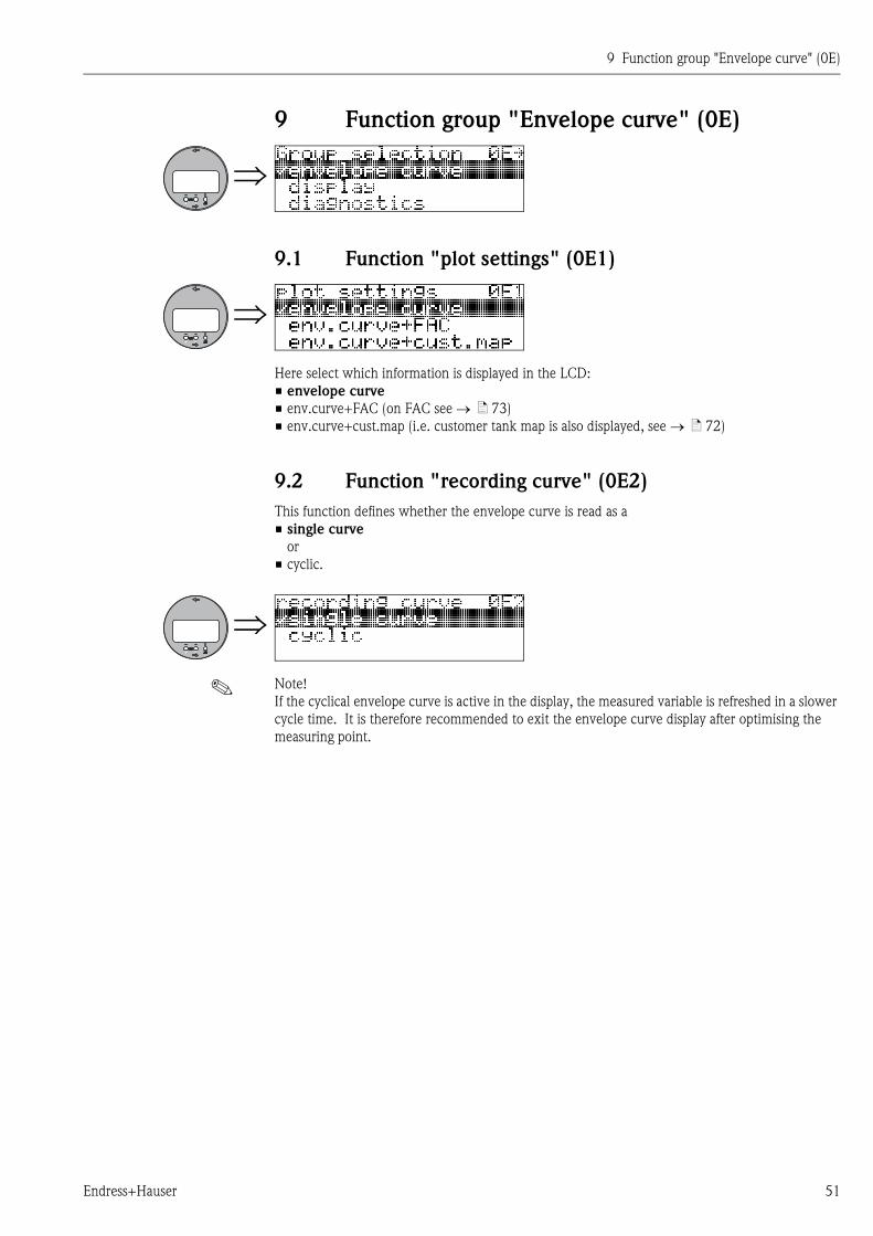
9 Function group "Envelope curve" (0E)
9.1 Function "plot settings" (0E1)
Here select which information is displayed in the LCD:
• envelope curve
• env.curve+FAC (on FAC see ä 73)
• env.curve+cust.map (i.e. customer tank map is also displayed, see ä 72)
9.2 Function "recording curve" (0E2)
This function defines whether the envelope curve is read as a
• single curve
or
• cyclic.
! Note!
If the cyclical envelope curve is active in the display, the measured variable is refreshed in a slower
cycle time. It is therefore recommended to exit the envelope curve display after optimising the
measuring point.
9 Function group "Envelope curve" (0E)
52 Endress+Hauser
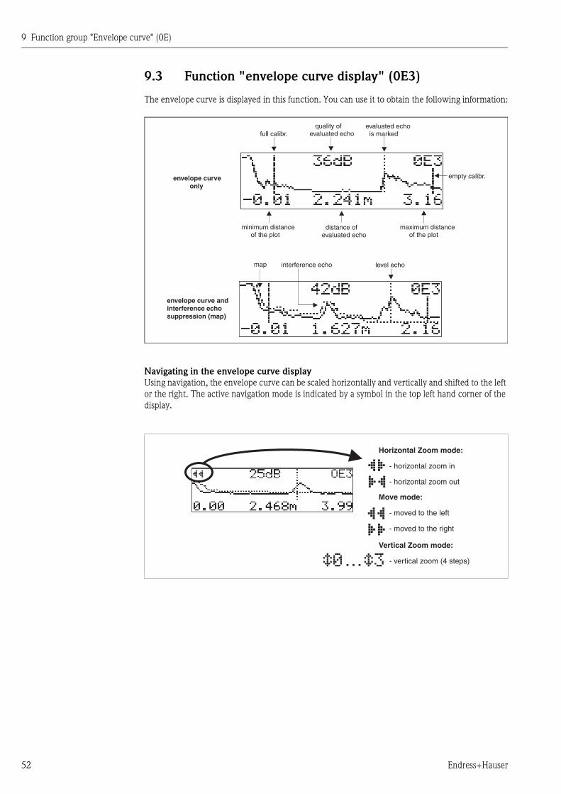
9.3 Function "envelope curve display" (0E3)
The envelope curve is displayed in this function. You can use it to obtain the following information:
Navigating in the envelope curve display
Using navigation, the envelope curve can be scaled horizontally and vertically and shifted to the left
or the right. The active navigation mode is indicated by a symbol in the top left hand corner of the
display.
minimum distanceof the plot
maximum distanceof the plot
distance ofevaluated echo
interference echo
evaluated echois marked
quality ofevaluated echo
empty calibr.envelope curveonly
envelope curve andinterference echosuppression (map)
level echomap
full calibr.
…
'�(
Move mode:
- m
-
oved to the left
moved to the right
Horizontal Zoom mode:
- h
-
orizontal zoom in
horizontal zoom out
Vertical Zoom mode:
- vertical zoom (4 steps)
9 Function group "Envelope curve" (0E)
Endress+Hauser 53
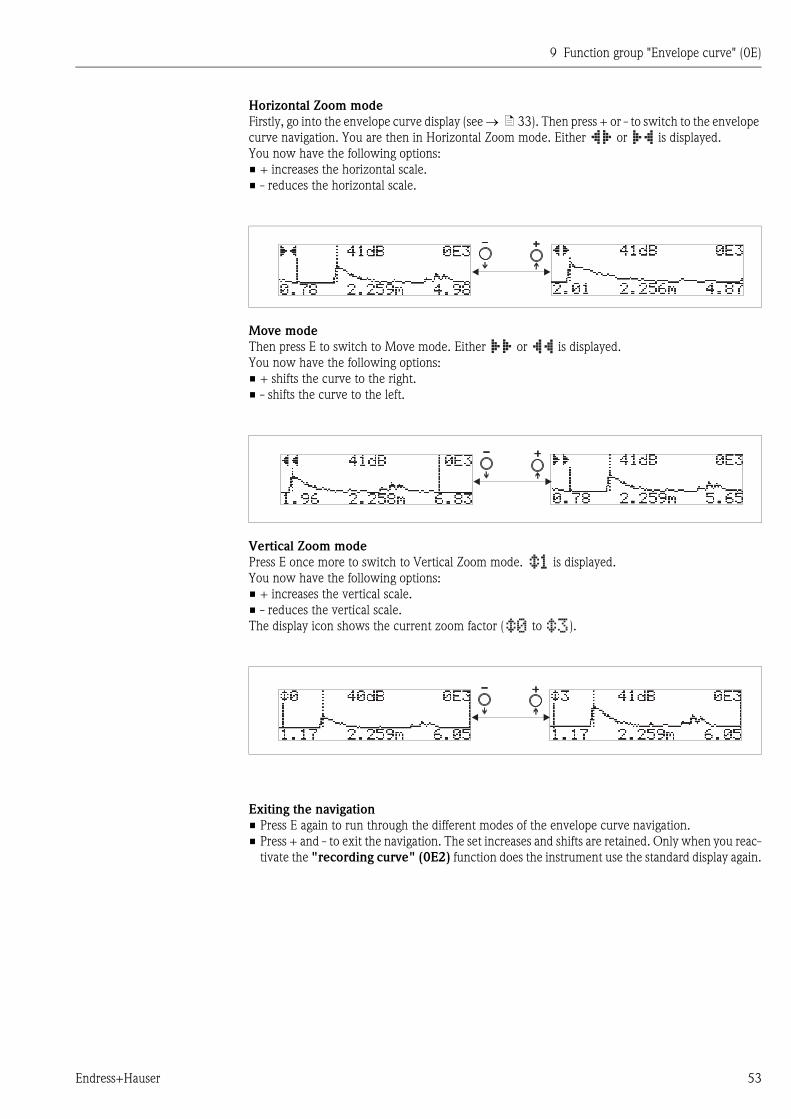
Horizontal Zoom mode
Firstly, go into the envelope curve display (see ä 33). Then press + or - to switch to the envelope
curve navigation. You are then in Horizontal Zoom mode. Either or is displayed.
You now have the following options:
• + increases the horizontal scale.
• - reduces the horizontal scale.
Move mode
Then press E to switch to Move mode. Either or is displayed.
You now have the following options:
• + shifts the curve to the right.
• - shifts the curve to the left.
Vertical Zoom mode
Press E once more to switch to Vertical Zoom mode. is displayed.
You now have the following options:
• + increases the vertical scale.
• - reduces the vertical scale.
The display icon shows the current zoom factor ( to ).
Exiting the navigation
• Press E again to run through the different modes of the envelope curve navigation.
• Press + and - to exit the navigation. The set increases and shifts are retained. Only when you reac-
tivate the "recording curve" (0E2) function does the instrument use the standard display again.

9 Function group "Envelope curve" (0E)
54 Endress+Hauser
10 Function group "display" (09)
Endress+Hauser 55
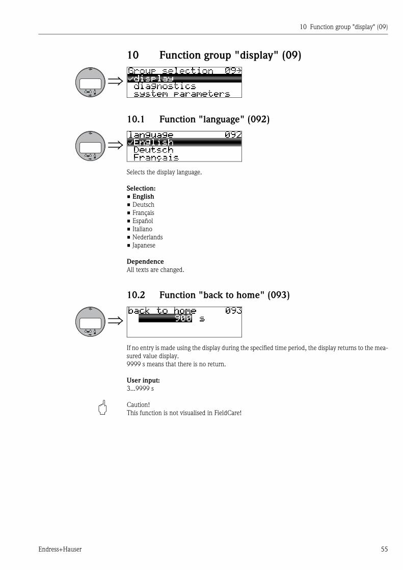
10 Function group "display" (09)
10.1 Function "language" (092)
Selects the display language.
Selection:
• English
• Deutsch
• Français
• Español
• Italiano
• Nederlands
• Japanese
Dependence
All texts are changed.
10.2 Function "back to home" (093)
If no entry is made using the display during the specified time period, the display returns to the mea-
sured value display.
9999 s means that there is no return.
User input:
3...9999 s
" Caution!
This function is not visualised in FieldCare!
10 Function group "display" (09)
56 Endress+Hauser
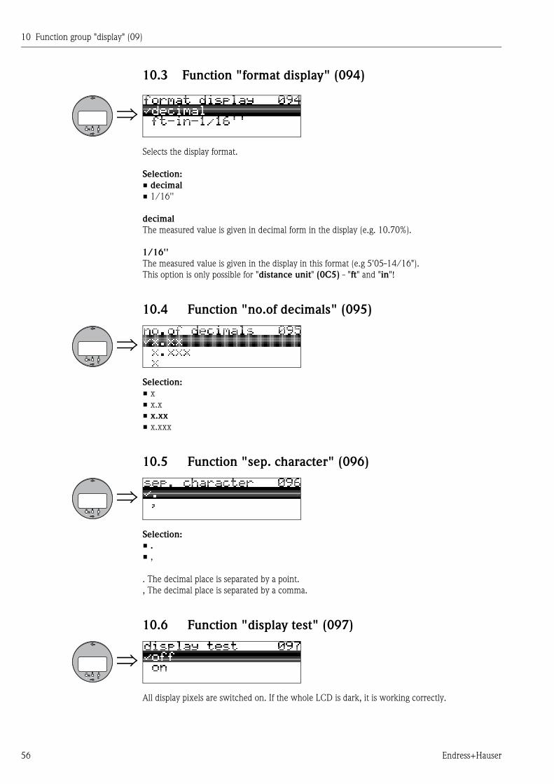
10.3 Function "format display" (094)
Selects the display format.
Selection:
• decimal
• 1/16''
decimal
The measured value is given in decimal form in the display (e.g. 10.70%).
1/16''
The measured value is given in the display in this format (e.g 5'05-14/16").
This option is only possible for "distance unit" (0C5) - "ft" and "in"!
10.4 Function "no.of decimals" (095)
Selection:
• x
• x.x
• x.xx
• x.xxx
10.5 Function "sep. character" (096)
Selection:
• .
• ,
. The decimal place is separated by a point.
, The decimal place is separated by a comma.
10.6 Function "display test" (097)
All display pixels are switched on. If the whole LCD is dark, it is working correctly.
11 Function group "diagnostics" (0A)
Endress+Hauser 57
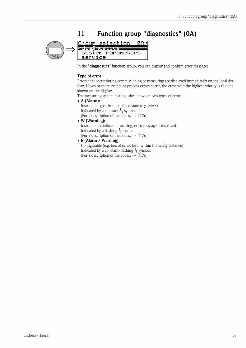
11 Function group "diagnostics" (0A)
In the "diagnostics" function group, you can display and confirm error messages.
Type of error
Errors that occur during commissioning or measuring are displayed immediately on the local dis-
play. If two or more system or process errors occur, the error with the highest priority is the one
shown on the display.
The measuring system distinguishes between two types of error:
• A (Alarm):
Instrument goes into a defined state (e.g. MAX)
Indicated by a constant symbol.
(For a description of the codes, ä 76)
• W (Warning):
Instrument continue measuring, error message is displayed.
Indicated by a flashing symbol.
(For a description of the codes, ä 76)
• E (Alarm / Warning):
Configurable (e.g. loss of echo, level within the safety distance)
Indicated by a constant/flashing symbol.
(For a description of the codes, ä 76)
11 Function group "diagnostics" (0A)
58 Endress+Hauser
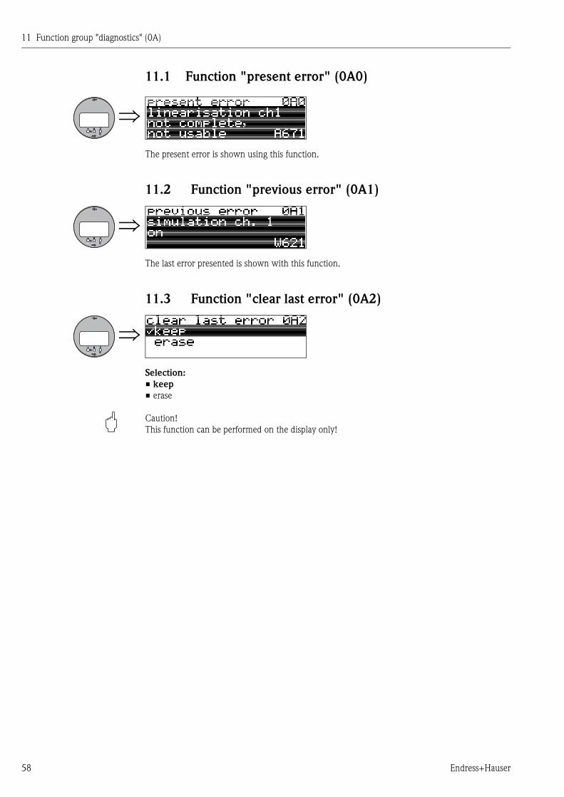
11.1 Function "present error" (0A0)
The present error is shown using this function.
11.2 Function "previous error" (0A1)
The last error presented is shown with this function.
11.3 Function "clear last error" (0A2)
Selection:
• keep
• erase
" Caution!
This function can be performed on the display only!
11 Function group "diagnostics" (0A)
Endress+Hauser 59
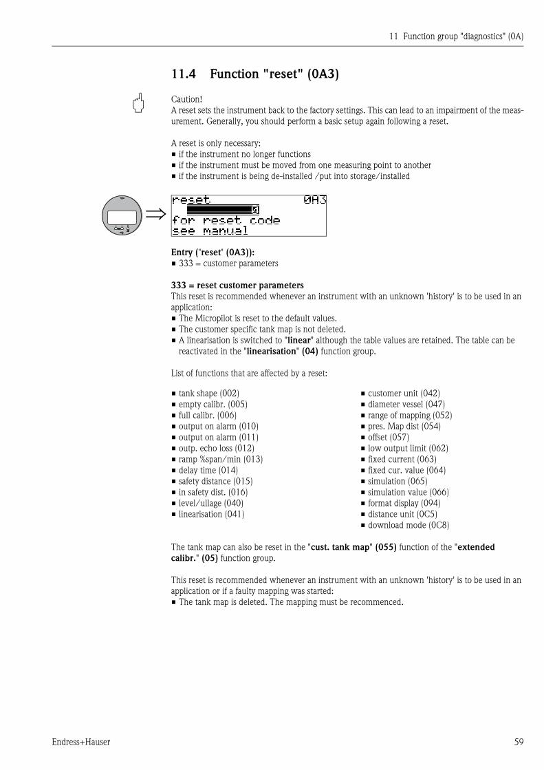
11.4 Function "reset" (0A3)
" Caution!
A reset sets the instrument back to the factory settings. This can lead to an impairment of the meas-
urement. Generally, you should perform a basic setup again following a reset.
A reset is only necessary:
• if the instrument no longer functions
• if the instrument must be moved from one measuring point to another
• if the instrument is being de-installed /put into storage/installed
Entry ("reset" (0A3)):
• 333 = customer parameters
333 = reset customer parameters
This reset is recommended whenever an instrument with an unknown 'history' is to be used in an
application:
• The Micropilot is reset to the default values.
• The customer specific tank map is not deleted.
• A linearisation is switched to "linear" although the table values are retained. The table can be
reactivated in the "linearisation" (04) function group.
List of functions that are affected by a reset:
The tank map can also be reset in the "cust. tank map" (055) function of the "extended
calibr." (05) function group.
This reset is recommended whenever an instrument with an unknown 'history' is to be used in an
application or if a faulty mapping was started:
• The tank map is deleted. The mapping must be recommenced.
• tank shape (002)
• empty calibr. (005)
• full calibr. (006)
• output on alarm (010)
• output on alarm (011)
• outp. echo loss (012)
• ramp %span/min (013)
• delay time (014)
• safety distance (015)
• in safety dist. (016)
• level/ullage (040)
• linearisation (041)
• customer unit (042)
• diameter vessel (047)
• range of mapping (052)
• pres. Map dist (054)
• offset (057)
• low output limit (062)
• fixed current (063)
• fixed cur. value (064)
• simulation (065)
• simulation value (066)
• format display (094)
• distance unit (0C5)
• download mode (0C8)
11 Function group "diagnostics" (0A)
60 Endress+Hauser
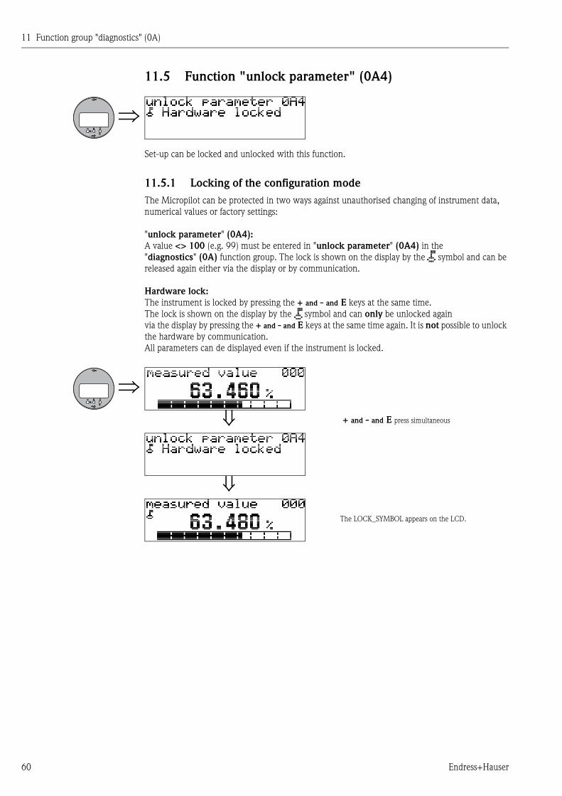
11.5 Function "unlock parameter" (0A4)
Set-up can be locked and unlocked with this function.
11.5.1 Locking of the configuration mode
The Micropilot can be protected in two ways against unauthorised changing of instrument data,
numerical values or factory settings:
"unlock parameter" (0A4):
A value <> 100 (e.g. 99) must be entered in "unlock parameter" (0A4) in the
"diagnostics" (0A) function group. The lock is shown on the display by the symbol and can be
released again either via the display or by communication.
Hardware lock:
The instrument is locked by pressing the + and - and E keys at the same time.
The lock is shown on the display by the symbol and can only be unlocked again
via the display by pressing the + and - and E keys at the same time again. It is not possible to unlock
the hardware by communication.
All parameters can de displayed even if the instrument is locked.
+ and - and E press simultaneous
The LOCK_SYMBOL appears on the LCD.
11 Function group "diagnostics" (0A)
Endress+Hauser 61
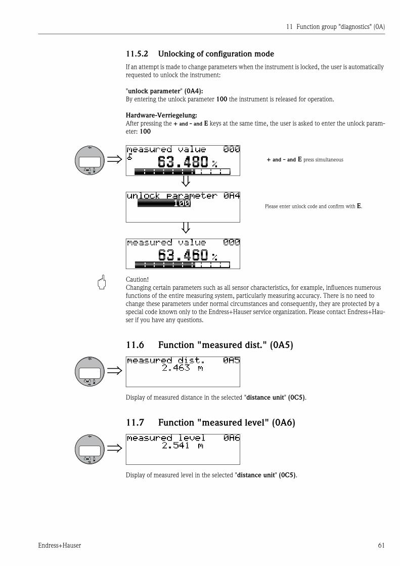
11.5.2 Unlocking of configuration mode
If an attempt is made to change parameters when the instrument is locked, the user is automatically
requested to unlock the instrument:
"unlock parameter" (0A4):
By entering the unlock parameter 100 the instrument is released for operation.
Hardware-Verriegelung:
After pressing the + and - and E keys at the same time, the user is asked to enter the unlock param-
eter: 100
" Caution!
Changing certain parameters such as all sensor characteristics, for example, influences numerous
functions of the entire measuring system, particularly measuring accuracy. There is no need to
change these parameters under normal circumstances and consequently, they are protected by a
special code known only to the Endress+Hauser service organization. Please contact Endress+Hau-
ser if you have any questions.
11.6 Function "measured dist." (0A5)
Display of measured distance in the selected "distance unit" (0C5).
11.7 Function "measured level" (0A6)
Display of measured level in the selected "distance unit" (0C5).
+ and - and E press simultaneous
Please enter unlock code and confirm with E.
11 Function group "diagnostics" (0A)
62 Endress+Hauser
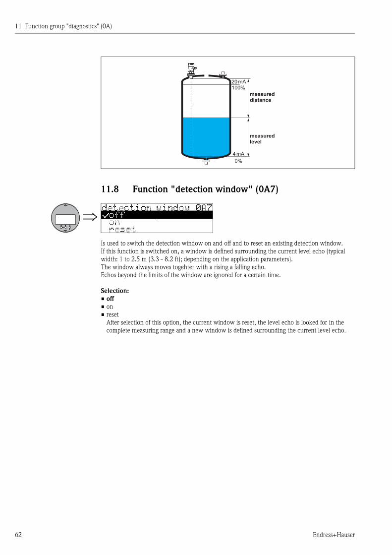
11.8 Function "detection window" (0A7)
Is used to switch the detection window on and off and to reset an existing detection window.
If this function is switched on, a window is defined surrounding the current level echo (typical
width: 1 to 2.5 m (3.3 - 8.2 ft); depending on the application parameters).
The window always moves togehter with a rising a falling echo.
Echos beyond the limits of the window are ignored for a certain time.
Selection:
• off
• on
• reset
After selection of this option, the current window is reset, the level echo is looked for in the
complete measuring range and a new window is defined surrounding the current level echo.
20 mA100%
4 mA
0%
measureddistance
measuredlevel
11 Function group "diagnostics" (0A)
Endress+Hauser 63
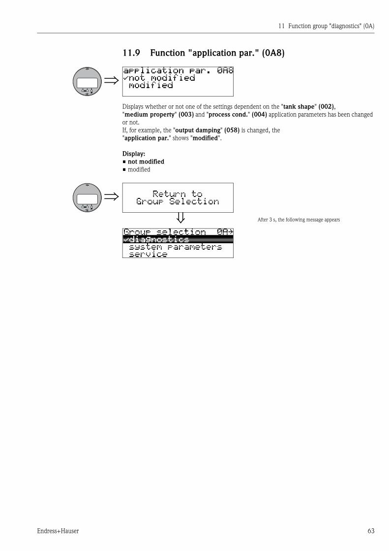
11.9 Function "application par." (0A8)
Displays whether or not one of the settings dependent on the "tank shape" (002),
"medium property" (003) and "process cond." (004) application parameters has been changed
or not.
If, for example, the "output damping" (058) is changed, the
"application par." shows "modified".
Display:
• not modified
• modified
After 3 s, the following message appears

11 Function group "diagnostics" (0A)
64 Endress+Hauser
12 Function group "system parameters" (0C)
Endress+Hauser 65
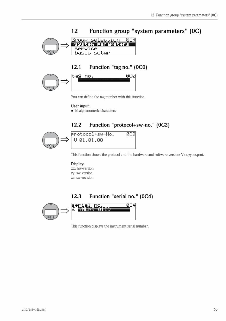
12 Function group "system parameters" (0C)
12.1 Function "tag no." (0C0)
You can define the tag number with this function.
User input:
• 16 alphanumeric characters
12.2 Function "protocol+sw-no." (0C2)
This function shows the protocol and the hardware and software version: Vxx.yy.zz.prot.
Display:
xx: hw-version
yy: sw-version
zz: sw-revision
12.3 Function "serial no." (0C4)
This function displays the instrument serial number.
��������)��*+�,
-��.,�.,��
�/0
12 Function group "system parameters" (0C)
66 Endress+Hauser
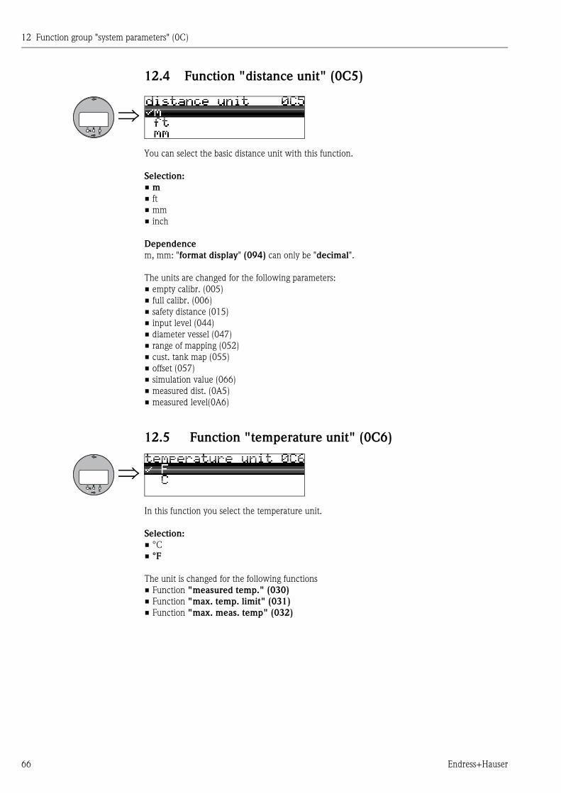
12.4 Function "distance unit" (0C5)
You can select the basic distance unit with this function.
Selection:
• m
• ft
• mm
• inch
Dependence
m, mm: "format display" (094) can only be "decimal".
The units are changed for the following parameters:
• empty calibr. (005)
• full calibr. (006)
• safety distance (015)
• input level (044)
• diameter vessel (047)
• range of mapping (052)
• cust. tank map (055)
• offset (057)
• simulation value (066)
• measured dist. (0A5)
• measured level(0A6)
12.5 Function "temperature unit" (0C6)
In this function you select the temperature unit.
Selection:
• °C
• °F
The unit is changed for the following functions
• Function "measured temp." (030)
• Function "max. temp. limit" (031)
• Function "max. meas. temp" (032)
12 Function group "system parameters" (0C)
Endress+Hauser 67
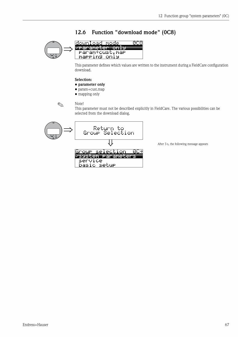
12.6 Function "download mode" (0C8)
This parameter defines which values are written to the instrument during a FieldCare configuration
download.
Selection:
• parameter only
• param+cust.map
• mapping only
! Note!
This parameter must not be described explicitly in FieldCare. The various possibilities can be
selected from the download dialog.
After 3 s, the following message appears

12 Function group "system parameters" (0C)
68 Endress+Hauser
13 Function group "service" (0D)
Endress+Hauser 69
13 Function group "service" (0D)
This function group is reserved for service purposes only.

13 Function group "service" (0D)
70 Endress+Hauser
14 Signal evaluation
Endress+Hauser 71
14 Signal evaluation
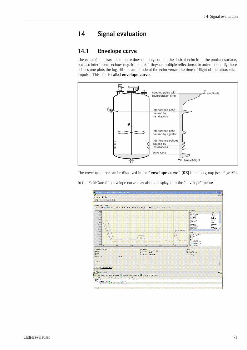
14.1 Envelope curve
The echo of an ultrasonic impulse does not only contain the desired echo from the product surface,
but also interference echoes (e.g. from tank fittings or multiple reflections). In order to identify these
echoes one plots the logarithmic amplitude of the echo versus the time-of-flight of the ultrasonic
impulse. This plot is called envelope curve.
The envelope curve can be displayed in the "envelope curve" (0E) function group (see Page 52).
In the FieldCare the envelope curve may also be displayed in the "envelope" menu:
y
x
sending pulse withreverberation time
interference echocaused byinstallations
interference echocaused by agitator
interference echoescaused byinstallations
level echo
time-of-flight
amplitude
14 Signal evaluation
72 Endress+Hauser
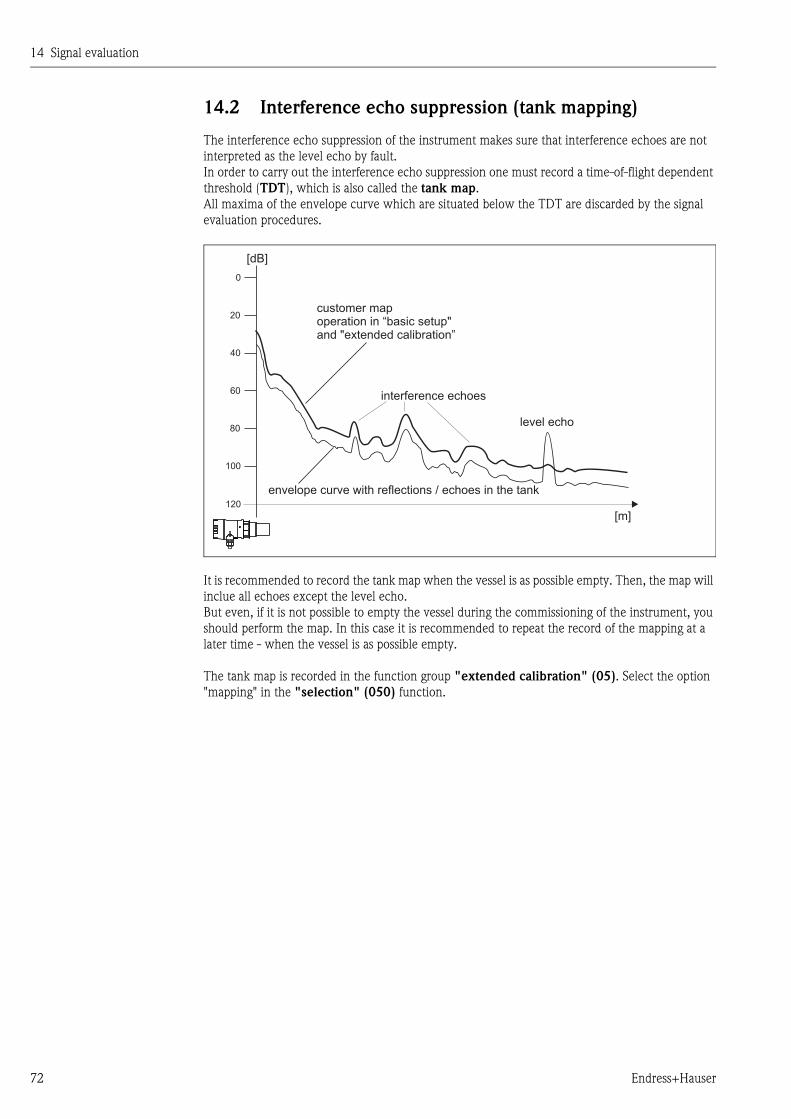
14.2 Interference echo suppression (tank mapping)
The interference echo suppression of the instrument makes sure that interference echoes are not
interpreted as the level echo by fault.
In order to carry out the interference echo suppression one must record a time-of-flight dependent
threshold (TDT), which is also called the tank map.
All maxima of the envelope curve which are situated below the TDT are discarded by the signal
evaluation procedures.
It is recommended to record the tank map when the vessel is as possible empty. Then, the map will
inclue all echoes except the level echo.
But even, if it is not possible to empty the vessel during the commissioning of the instrument, you
should perform the map. In this case it is recommended to repeat the record of the mapping at a
later time - when the vessel is as possible empty.
The tank map is recorded in the function group "extended calibration" (05). Select the option
"mapping" in the "selection" (050) function.
0
20
40
60
80
100
120
[dB]
[m]
envelope curve with reflections / echoes in the tank
customer mapoperation in “basic setup"and "extended calibration”
interference echoes
level echo
14 Signal evaluation
Endress+Hauser 73
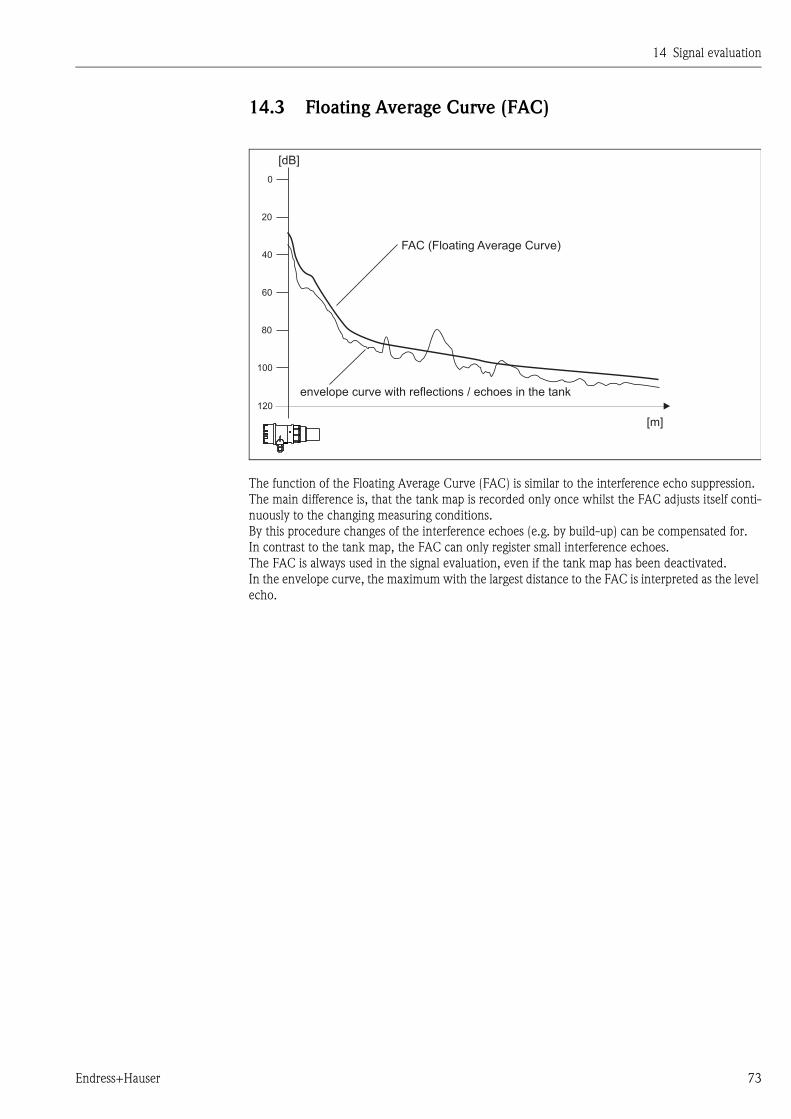
14.3 Floating Average Curve (FAC)
The function of the Floating Average Curve (FAC) is similar to the interference echo suppression.
The main difference is, that the tank map is recorded only once whilst the FAC adjusts itself conti-
nuously to the changing measuring conditions.
By this procedure changes of the interference echoes (e.g. by build-up) can be compensated for.
In contrast to the tank map, the FAC can only register small interference echoes.
The FAC is always used in the signal evaluation, even if the tank map has been deactivated.
In the envelope curve, the maximum with the largest distance to the FAC is interpreted as the level
echo.
0
20
40
60
80
100
120
[dB]
[m]
envelope curve with reflections / echoes in the tank
FAC (Floating Average Curve)

14 Signal evaluation
74 Endress+Hauser
15 Trouble shooting
Endress+Hauser 75
15 Trouble shooting
15.1 System error messages
Current error
Errors which the instrument detects during commissioning or operation are displayed:
• In the "measured value" (000) function
• In the "diagnostics" (0A) function group in the "present error" (0A0) function
(only the highest priority error is displayed; in the case of multiple errors, you can scroll between
the different error messages by pressing + or - .)
Last error
The last error is displayed in the "diagnostics" (0A) function group in the "previous error"
(0A1) function. This display can be deleted in the "clear last error" (0A2) function.
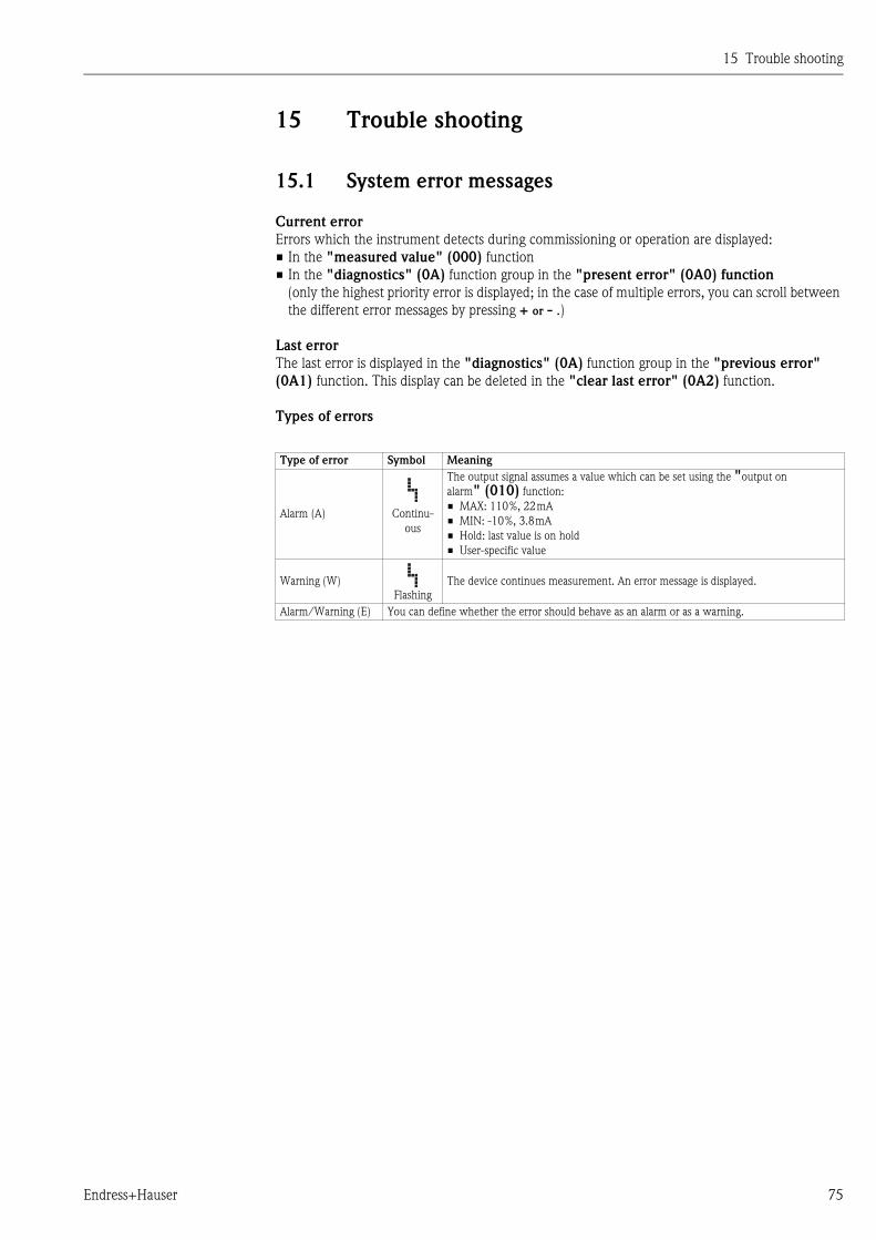
Types of errors
Type of error Symbol Meaning
Alarm (A) Continu-
ous
The output signal assumes a value which can be set using the "output on
alarm" (010) function:
• MAX: 110%, 22mA
• MIN: -10%, 3.8mA
• Hold: last value is on hold
• User-specific value
Warning (W)
Flashing
The device continues measurement. An error message is displayed.
Alarm/Warning (E) You can define whether the error should behave as an alarm or as a warning.
15 Trouble shooting
76 Endress+Hauser
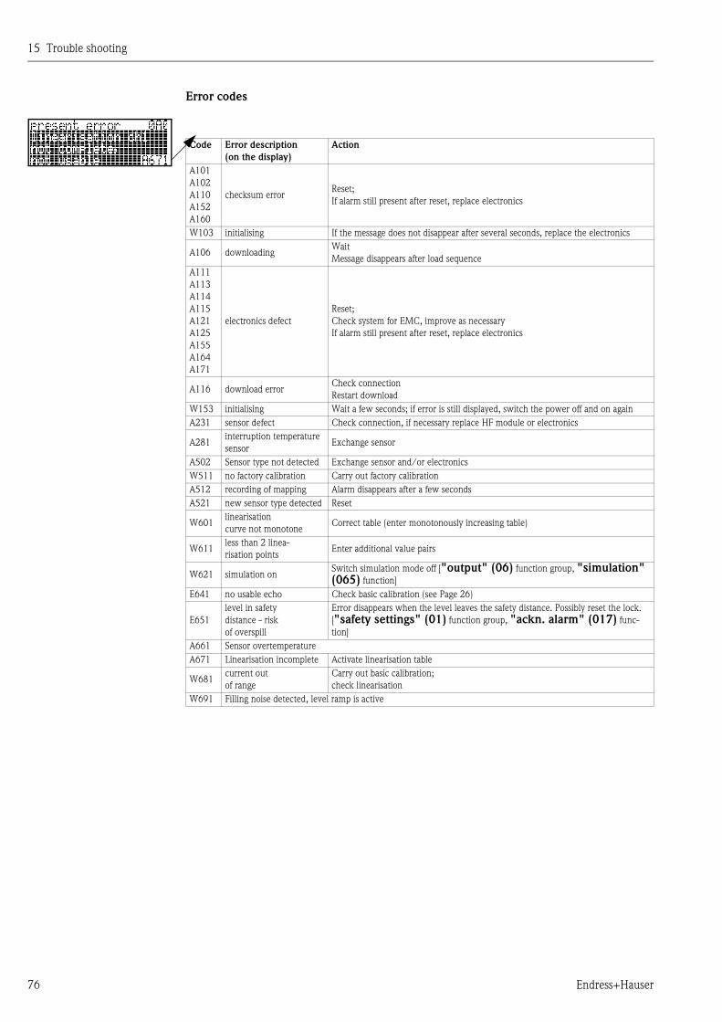
Error codes
Code Error description
(on the display)
Action
A101
A102
A110
A152
A160
checksum errorReset;
If alarm still present after reset, replace electronics
W103 initialising If the message does not disappear after several seconds, replace the electronics
A106 downloadingWait
Message disappears after load sequence
A111
A113
A114
A115
A121
A125
A155
A164
A171
electronics defect
Reset;
Check system for EMC, improve as necessary
If alarm still present after reset, replace electronics
A116 download errorCheck connection
Restart download
W153 initialising Wait a few seconds; if error is still displayed, switch the power off and on again
A231 sensor defect Check connection, if necessary replace HF module or electronics
A281interruption temperature
sensorExchange sensor
A502 Sensor type not detected Exchange sensor and/or electronics
W511 no factory calibration Carry out factory calibration
A512 recording of mapping Alarm disappears after a few seconds
A521 new sensor type detected Reset
W601linearisation
curve not monotoneCorrect table (enter monotonously increasing table)
W611less than 2 linea-
risation pointsEnter additional value pairs
W621 simulation onSwitch simulation mode off ["output" (06) function group, "simulation" (065) function]
E641 no usable echo Check basic calibration (see Page 26)
E651
level in safety
distance - risk
of overspill
Error disappears when the level leaves the safety distance. Possibly reset the lock.
["safety settings" (01) function group, "ackn. alarm" (017) func-
tion]
A661 Sensor overtemperature
A671 Linearisation incomplete Activate linearisation table
W681current out
of range
Carry out basic calibration;
check linearisation
W691 Filling noise detected, level ramp is active
15 Trouble shooting
Endress+Hauser 77
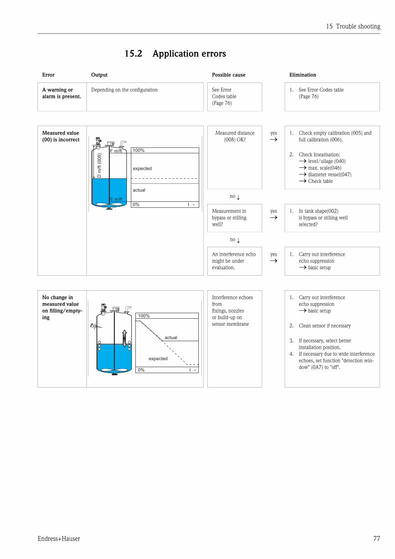
15.2 Application errors
Error Output Possible cause Elimination
A warning or
alarm is present.
Depending on the configuration See Error
Codes table
(Page 76)
1. See Error Codes table
(Page 76)
Measured value
(00) is incorrect
Measured distance
(008) OK?
yes
1. Check empty calibration (005) and
full calibration (006).
2. Check linearisation:
level/ullage (040)
max. scale(046)
diameter vessel(047)
Check table
no
Measurement in
bypass or stilling
well?
yes
1. In tank shape(002)
is bypass or stiliing well
selected?
no
An interference echo
might be under
evaluation.
yes
1. Carry out interference
echo suppression
basic setup
No change in
measured value
on filling/empty-
ing
Interference echoes
from
fixings, nozzles
or build-up on
sensor membrane
1. Carry out interference
echo suppression
basic setup
2. Clean sensor if necessary
3. If necessary, select better
installation position.
4. If necessary due to wide interference
echoes, set function "detection win-
dow" (0A7) to "off".
100%F m/ft
E m/ft0% t →
Dm
/ft(0
08
)
actual
expected
100%
0% t →
actual
expected

15 Trouble shooting
78 Endress+Hauser
Error Output Possible cause Elimination
With an uneven
surface
(e.g. filling, emp-
tying, running
agitator) the
measured value
may jump spo-
radically to
higher
levels
Signal is weakened by
uneven surface —
periodically
interference echos,
e.g. from internals,
are stronger
1. Carry out interference
echo suppression basic setup
2. Set the process cond. (004) to
"calm surface" or
"add. agitator"
3. Increase output damping (058)
4. If necessary, select a different instal-
lation position and/or a larger sensor
On filling/emp-
tying
the measured
value drops
Multiple echoes yes
1. Check tank shape (002),
e.g. "dome ceiling" or
"horizontal cyl."
2. In the blocking distance range (059)
there is no echo evaluation
3. If possible, do not select a central
installation position
4. Possible user stilling well/echo guide
pipe
E 641 (echo loss) Level echo is too
weak.
Possible causes:
• Uneven surface
through filling/
emptying
• Active agitator
• Foam
• Sensor not aligned
parallel to product
surface
yes
1. Check application parameters
(002), (003) and (004)
2. If necessary, select a different instal-
lation position and/or a larger sensor
3. Align the sensor parallel to the prod-
uct surface (particularly for bulk sol-
ids applications)
100%
0% t →
actual
expected
100%
0% t →
actual
expected
100%
0% t →
actual
expected
100%
E 641
0% t
actual
expected
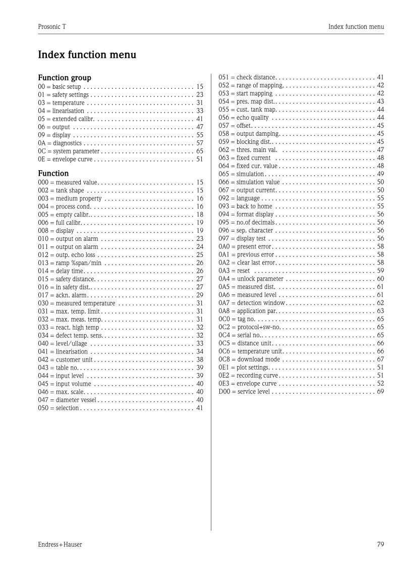
Prosonic T Index function menu
Endress+Hauser 79
Index function menu
Function group00 = basic setup . . . . . . . . . . . . . . . . . . . . . . . . . . . . . . . . 15
01 = safety settings . . . . . . . . . . . . . . . . . . . . . . . . . . . . . . 23
03 = temperature . . . . . . . . . . . . . . . . . . . . . . . . . . . . . . . 31
04 = linearisation . . . . . . . . . . . . . . . . . . . . . . . . . . . . . . . 33
05 = extended calibr. . . . . . . . . . . . . . . . . . . . . . . . . . . . . 41
06 = output . . . . . . . . . . . . . . . . . . . . . . . . . . . . . . . . . . . 47
09 = display . . . . . . . . . . . . . . . . . . . . . . . . . . . . . . . . . . . 55
0A = diagnostics . . . . . . . . . . . . . . . . . . . . . . . . . . . . . . . . 57
0C = system parameter . . . . . . . . . . . . . . . . . . . . . . . . . . . 65
0E = envelope curve . . . . . . . . . . . . . . . . . . . . . . . . . . . . . 51
Function000 = measured value. . . . . . . . . . . . . . . . . . . . . . . . . . . . 15
002 = tank shape . . . . . . . . . . . . . . . . . . . . . . . . . . . . . . . 15
003 = medium property . . . . . . . . . . . . . . . . . . . . . . . . . . 16
004 = process cond. . . . . . . . . . . . . . . . . . . . . . . . . . . . . . 16
005 = empty calibr.. . . . . . . . . . . . . . . . . . . . . . . . . . . . . . 18
006 = full calibr. . . . . . . . . . . . . . . . . . . . . . . . . . . . . . . . . 19
008 = display . . . . . . . . . . . . . . . . . . . . . . . . . . . . . . . . . . 19
010 = output on alarm . . . . . . . . . . . . . . . . . . . . . . . . . . . 23
011 = output on alarm . . . . . . . . . . . . . . . . . . . . . . . . . . . 24
012 = outp. echo loss . . . . . . . . . . . . . . . . . . . . . . . . . . . . 25
013 = ramp %span/min . . . . . . . . . . . . . . . . . . . . . . . . . . 26
014 = delay time. . . . . . . . . . . . . . . . . . . . . . . . . . . . . . . . 26
015 = safety distance. . . . . . . . . . . . . . . . . . . . . . . . . . . . . 27
016 = in safety dist.. . . . . . . . . . . . . . . . . . . . . . . . . . . . . . 27
017 = ackn. alarm. . . . . . . . . . . . . . . . . . . . . . . . . . . . . . . 29
030 = measured temperature . . . . . . . . . . . . . . . . . . . . . . 31
031 = max. temp. limit . . . . . . . . . . . . . . . . . . . . . . . . . . . 31
032 = max. meas. temp. . . . . . . . . . . . . . . . . . . . . . . . . . . 31
033 = react. high temp . . . . . . . . . . . . . . . . . . . . . . . . . . . 32
034 = defect temp. sens. . . . . . . . . . . . . . . . . . . . . . . . . . . 32
040 = level/ullage . . . . . . . . . . . . . . . . . . . . . . . . . . . . . . 33
041 = linearisation . . . . . . . . . . . . . . . . . . . . . . . . . . . . . . 34
042 = customer unit . . . . . . . . . . . . . . . . . . . . . . . . . . . . . 38
043 = table no. . . . . . . . . . . . . . . . . . . . . . . . . . . . . . . . . . 39
044 = input level . . . . . . . . . . . . . . . . . . . . . . . . . . . . . . . 39
045 = input volume . . . . . . . . . . . . . . . . . . . . . . . . . . . . . 40
046 = max. scale. . . . . . . . . . . . . . . . . . . . . . . . . . . . . . . . 40
047 = diameter vessel . . . . . . . . . . . . . . . . . . . . . . . . . . . . 40
050 = selection . . . . . . . . . . . . . . . . . . . . . . . . . . . . . . . . . 41
051 = check distance. . . . . . . . . . . . . . . . . . . . . . . . . . . . . 41
052 = range of mapping. . . . . . . . . . . . . . . . . . . . . . . . . . . 42
053 = start mapping . . . . . . . . . . . . . . . . . . . . . . . . . . . . . 42
054 = pres. map dist.. . . . . . . . . . . . . . . . . . . . . . . . . . . . . 43
055 = cust. tank map. . . . . . . . . . . . . . . . . . . . . . . . . . . . . 44
056 = echo quality . . . . . . . . . . . . . . . . . . . . . . . . . . . . . . 44
057 = offset. . . . . . . . . . . . . . . . . . . . . . . . . . . . . . . . . . . . 45
058 = output damping. . . . . . . . . . . . . . . . . . . . . . . . . . . . 45
059 = blocking dist.. . . . . . . . . . . . . . . . . . . . . . . . . . . . . . 45
062 = thres. main val. . . . . . . . . . . . . . . . . . . . . . . . . . . . 47
063 = fixed current . . . . . . . . . . . . . . . . . . . . . . . . . . . . . 48
064 = fixed cur. value . . . . . . . . . . . . . . . . . . . . . . . . . . . . 48
065 = simulation . . . . . . . . . . . . . . . . . . . . . . . . . . . . . . . . 49
066 = simulation value . . . . . . . . . . . . . . . . . . . . . . . . . . . 50
067 = output current. . . . . . . . . . . . . . . . . . . . . . . . . . . . . 50
092 = language . . . . . . . . . . . . . . . . . . . . . . . . . . . . . . . . . 55
093 = back to home . . . . . . . . . . . . . . . . . . . . . . . . . . . . . 55
094 = format display . . . . . . . . . . . . . . . . . . . . . . . . . . . . . 56
095 = no.of decimals . . . . . . . . . . . . . . . . . . . . . . . . . . . . . 56
096 = sep. character . . . . . . . . . . . . . . . . . . . . . . . . . . . . . 56
097 = display test . . . . . . . . . . . . . . . . . . . . . . . . . . . . . . . 56
0A0 = present error . . . . . . . . . . . . . . . . . . . . . . . . . . . . . . 58
0A1 = previous error . . . . . . . . . . . . . . . . . . . . . . . . . . . . . 58
0A2 = clear last error. . . . . . . . . . . . . . . . . . . . . . . . . . . . . 58
0A3 = reset . . . . . . . . . . . . . . . . . . . . . . . . . . . . . . . . . . . 59
0A4 = unlock parameter . . . . . . . . . . . . . . . . . . . . . . . . . . 60
0A5 = measured dist. . . . . . . . . . . . . . . . . . . . . . . . . . . . . 61
0A6 = measured level . . . . . . . . . . . . . . . . . . . . . . . . . . . . 61
0A7 = detection window. . . . . . . . . . . . . . . . . . . . . . . . . . 62
0A8 = application par. . . . . . . . . . . . . . . . . . . . . . . . . . . . . 63
0C0 = tag no. . . . . . . . . . . . . . . . . . . . . . . . . . . . . . . . . . . 65
0C2 = protocol+sw-no. . . . . . . . . . . . . . . . . . . . . . . . . . . . 65
0C4 = serial no.. . . . . . . . . . . . . . . . . . . . . . . . . . . . . . . . . 65
0C5 = distance unit . . . . . . . . . . . . . . . . . . . . . . . . . . . . . . 66
0C6 = temperature unit. . . . . . . . . . . . . . . . . . . . . . . . . . . 66
0C8 = download mode . . . . . . . . . . . . . . . . . . . . . . . . . . . 67
0E1 = plot settings. . . . . . . . . . . . . . . . . . . . . . . . . . . . . . . 51
0E2 = recording curve . . . . . . . . . . . . . . . . . . . . . . . . . . . . 51
0E3 = envelope curve . . . . . . . . . . . . . . . . . . . . . . . . . . . . 52
D00 = service level . . . . . . . . . . . . . . . . . . . . . . . . . . . . . . 69

www.endress.com/worldwide
BA00388F/00/EN/13.12
71164377
FM+SGML9.0
71164377