Range-Free Sensor Localization Simulations with ROCRSSI-based Algorithm Matt Magpayo...
21
Range-Free Sensor Localization Simulations with ROCRSSI-based Algorithm Matt Magpayo [email protected]
-
Upload
alfred-benson -
Category
Documents
-
view
218 -
download
0
Transcript of Range-Free Sensor Localization Simulations with ROCRSSI-based Algorithm Matt Magpayo...
Range-Free Sensor Localization Simulations with ROCRSSI-based Algorithm
Matt Magpayo

Presentation OutlinePresentation Outline
• Introduction to WSNIntroduction to WSN
• The Localization ProblemThe Localization Problem
• ROCRSSI and Signed-ROCRSSIROCRSSI and Signed-ROCRSSI
• Implementation and Simulation ResultsImplementation and Simulation Results
• Future WorkFuture Work
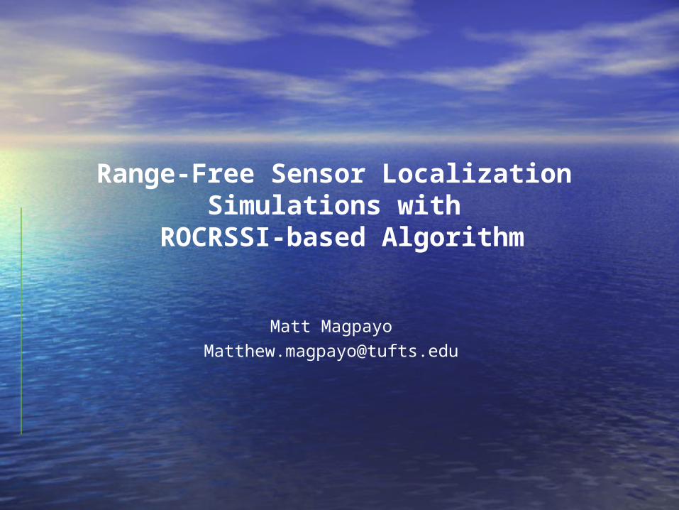
Why Wireless Sensors Why Wireless Sensors Networks?Networks?
• WSNs involve the use of numerous small, wireless sensors that WSNs involve the use of numerous small, wireless sensors that are inexpensive and easily deployed.are inexpensive and easily deployed.
• Various applicationsVarious applications– Habitat monitoring Habitat monitoring
• (forest fire detection, water pollutants)(forest fire detection, water pollutants)
– Military surveillanceMilitary surveillance• (enemy tracking, sniper detection)(enemy tracking, sniper detection)
– Medical careMedical care• (smart hospitals, patient monitoring)(smart hospitals, patient monitoring)
• Introduces Design ChallengesIntroduces Design Challenges– Limited storage capacity, limited energy supply, limited communication Limited storage capacity, limited energy supply, limited communication
bandwidthbandwidth– All designs must take each into consideration.All designs must take each into consideration.
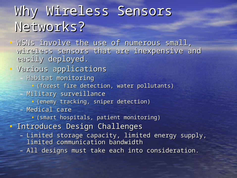
WSN Research AreasWSN Research Areas
• TrackingTracking– Detection and tracking in a sensor networkDetection and tracking in a sensor network
• RoutingRouting– Routing protocols of the sensor network.Routing protocols of the sensor network.
• LocalizationLocalization– Location information of sensor nodes.Location information of sensor nodes.
LocalizationLocalization
• Solution #1: Marking the location of each node as Solution #1: Marking the location of each node as deployeddeployed– Impractical for large number of nodes, limited mobilityImpractical for large number of nodes, limited mobility
• Solution #2: GPS capabilities on all nodesSolution #2: GPS capabilities on all nodes– Expensive and more energy consumptionExpensive and more energy consumption
• Solution #3: Anchor NodesSolution #3: Anchor Nodes– Have a small subset of nodes have GPS. Sensors use them to Have a small subset of nodes have GPS. Sensors use them to
find relative location.find relative location.• Using Ranged-Based and Ranged-Free schemesUsing Ranged-Based and Ranged-Free schemes
Range-Based Localization
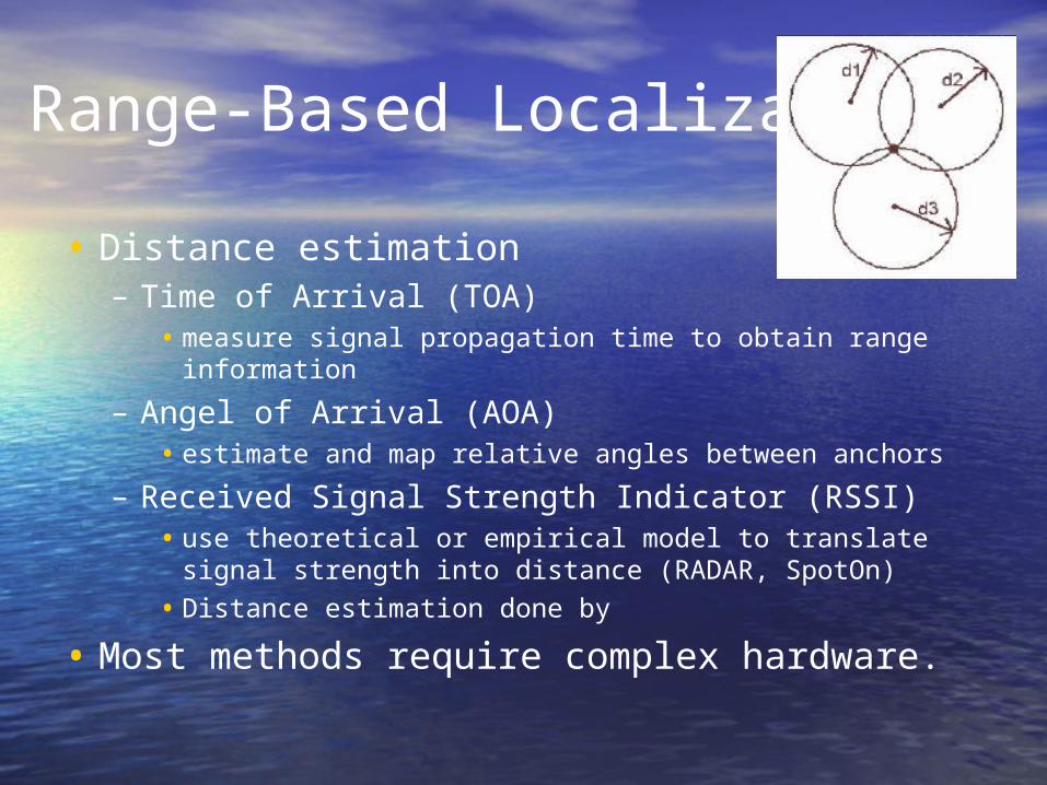
• Distance estimation – Time of Arrival (TOA)
• measure signal propagation time to obtain range information
– Angel of Arrival (AOA)• estimate and map relative angles between anchors
– Received Signal Strength Indicator (RSSI)• use theoretical or empirical model to translate signal strength into
distance (RADAR, SpotOn)
• Distance estimation done by
• Most methods require complex hardware.
Ranged-Free LocalizationRanged-Free Localization
• Never tries to estimate the absolute point-to-point distance.Never tries to estimate the absolute point-to-point distance.• Some available solutions:Some available solutions:
– Centroid Algorithm• After receiving location information of several anchors node, use centroid
formula to estimate its location
– DV-HOP• Anchor node flood their location and hop count throughout the network.
Nodes calculate their position based on the received anchor location, hop count and average-distance per hop.
– Ring Overlapping based on Comparison of Received Signal Strength Indicator (ROCRSSI)
• Reduces location of sensor to a ring of finite definite thickness by comparing RSSI values.
Summary of ROCRSSISummary of ROCRSSI
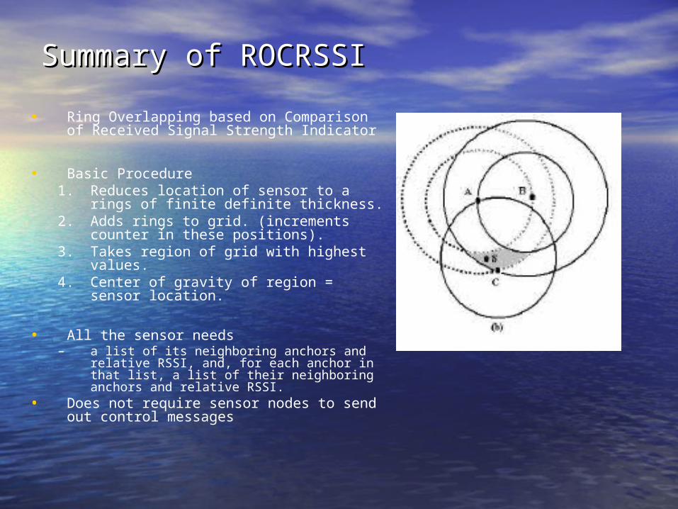
• Ring Overlapping based on Comparison of Received Signal Strength Indicator
• Basic Procedure1. Reduces location of sensor to a rings of
finite definite thickness.2. Adds rings to grid. (increments counter
in these positions).3. Takes region of grid with highest values.4. Center of gravity of region = sensor
location.
• All the sensor needs– a list of its neighboring anchors and
relative RSSI, and, for each anchor in that list, a list of their neighboring anchors and relative RSSI.
• Does not require sensor nodes to send out control messages
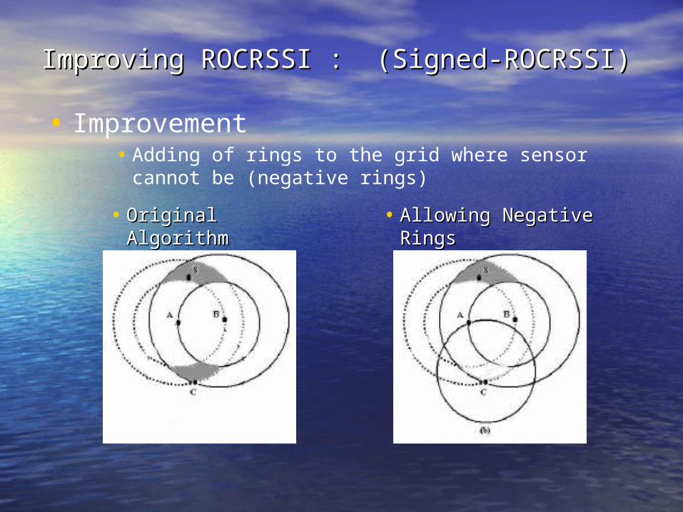
Improving ROCRSSI : (Signed-ROCRSSI) Improving ROCRSSI : (Signed-ROCRSSI)
• Improvement• Adding of rings to the grid where sensor cannot be (negative
rings)
• Original Original AlgorithmAlgorithm
• Allowing Negative Allowing Negative RingsRings
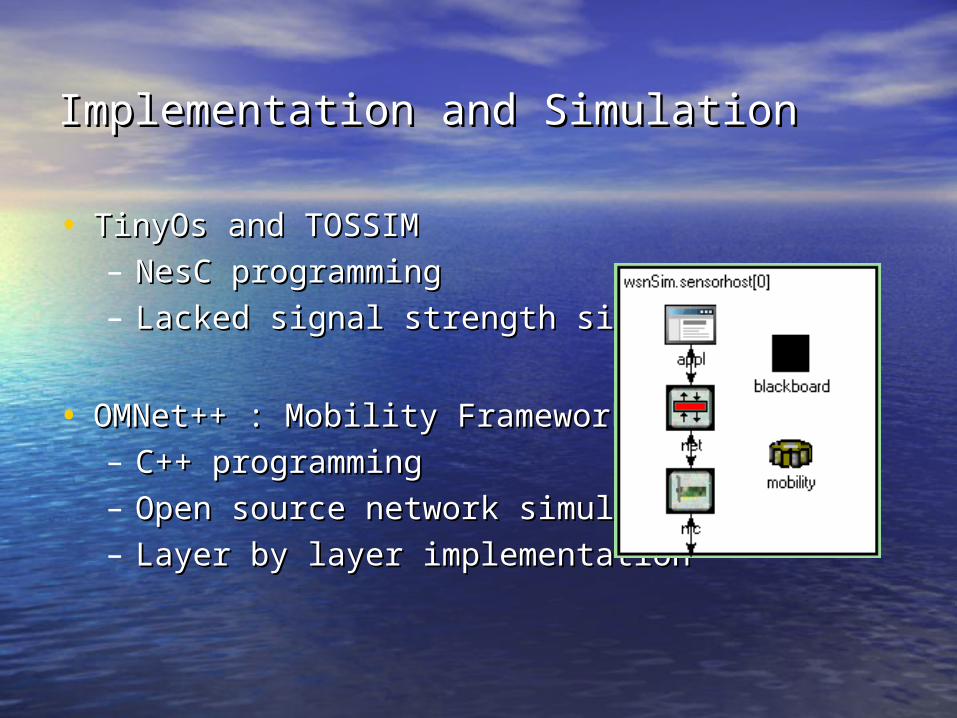
Implementation and SimulationImplementation and Simulation
• TinyOs and TOSSIMTinyOs and TOSSIM
– NesC programmingNesC programming
– Lacked signal strength simulationLacked signal strength simulation
• OMNet++ : Mobility FrameworkOMNet++ : Mobility Framework
– C++ programmingC++ programming
– Open source network simulatorOpen source network simulator
– Layer by layer implementationLayer by layer implementation

Simulation TimelineSimulation Timeline
1.1. All anchors send a broadcast message with its location.All anchors send a broadcast message with its location.
2.2. Other anchors upon receiving broadcast messages, store the Other anchors upon receiving broadcast messages, store the locations and RSSI of the message in a list of their locations and RSSI of the message in a list of their neighboring anchors.neighboring anchors.
3.3. After a predetermined interval of time, each anchor then After a predetermined interval of time, each anchor then broadcast its location, and its list of neighbors and RSSIs.broadcast its location, and its list of neighbors and RSSIs.
4.4. This broadcast is heard from sensor nodes, received, and This broadcast is heard from sensor nodes, received, and used to compute its location.used to compute its location.

Preliminary SimulationsPreliminary Simulations
• Real loc = [ 350 , 250 ]Real loc = [ 350 , 250 ]• Estimated loc = [ 374 , 258 ]Estimated loc = [ 374 , 258 ]
Sensor # Real Location
EstimatedLocation
0 350,250 331,257
1 450,200 457,195
2 375,150 374,152
3 375,275 331,257
4 180,250 170,220
5 300,200 299,192
6 550,200 516,165
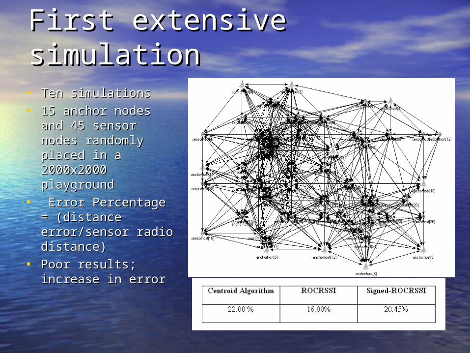
First extensive simulationFirst extensive simulation
• Ten simulationsTen simulations
• 15 anchor nodes 15 anchor nodes and 45 sensor nodes and 45 sensor nodes randomly placed in randomly placed in a 2000x2000 a 2000x2000 playgroundplayground
• Error Percentage = Error Percentage = (distance (distance error/sensor radio error/sensor radio distance)distance)
• Poor results; Poor results; increase in errorincrease in error
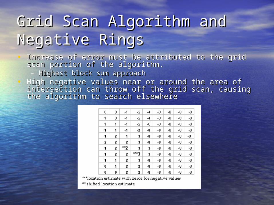
Grid Scan Algorithm and Grid Scan Algorithm and Negative RingsNegative Rings• Increase of error must be attributed to the grid scan portion Increase of error must be attributed to the grid scan portion
of the algorithm. of the algorithm. – Highest block sum approachHighest block sum approach
• High negative values near or around the area of High negative values near or around the area of intersection can throw off the grid scan, causing the intersection can throw off the grid scan, causing the algorithm to search elsewherealgorithm to search elsewhere
Alleviating shiftingAlleviating shifting
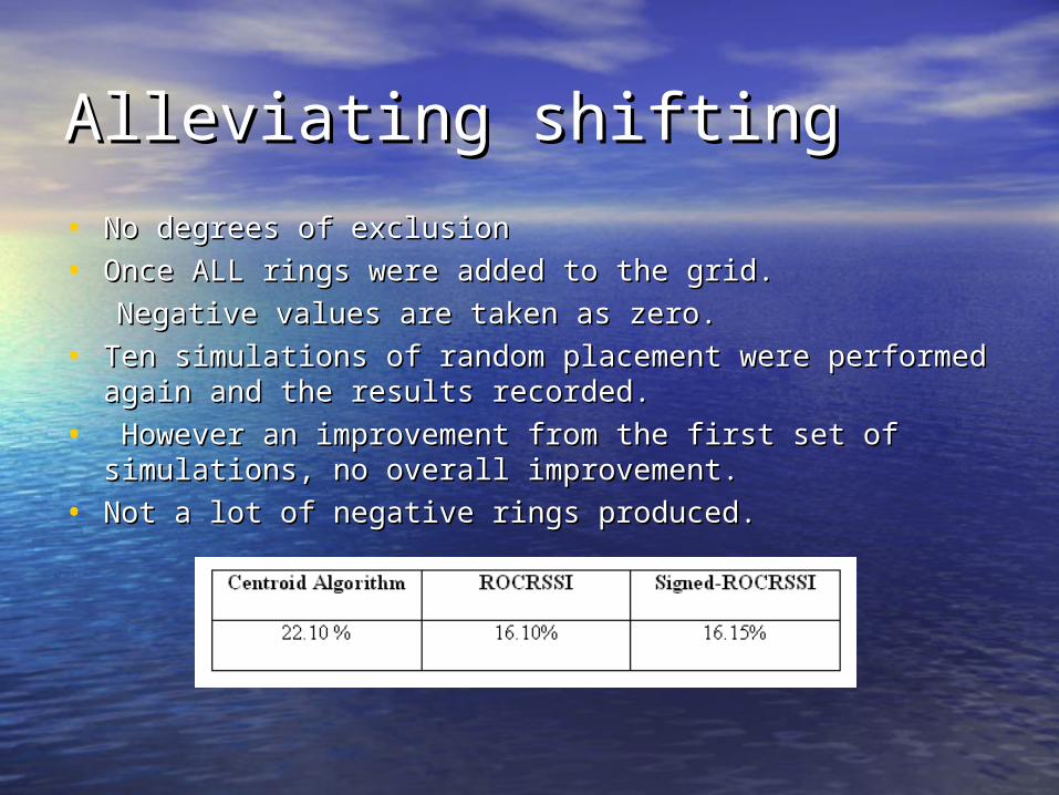
• No degrees of exclusionNo degrees of exclusion
• Once ALL rings were added to the grid.Once ALL rings were added to the grid.
Negative values are taken as zero.Negative values are taken as zero.
• Ten simulations of random placement were performed Ten simulations of random placement were performed again and the results recorded.again and the results recorded.
• However an improvement from the first set of simulations, However an improvement from the first set of simulations, no overall improvement.no overall improvement.
• Not a lot of negative rings produced.Not a lot of negative rings produced.
Further simulationsFurther simulations
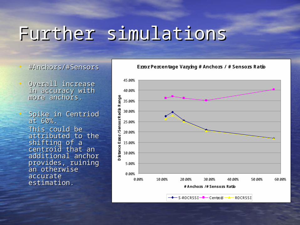
• #Anchors/#Sensors#Anchors/#Sensors
• Overall increase in Overall increase in accuracy with more accuracy with more anchors.anchors.
• Spike in Centriod at Spike in Centriod at 60%. 60%. This could be This could be attributed to the attributed to the shifting of a shifting of a centroid that an centroid that an additional anchor additional anchor provides, ruining an provides, ruining an otherwise accurate otherwise accurate estimation. estimation.
Error Percentage Varying # Anchors / # Sensors Ratio
0.00%
5.00%
10.00%
15.00%
20.00%
25.00%
30.00%
35.00%
40.00%
45.00%
0.00% 10.00% 20.00% 30.00% 40.00% 50.00% 60.00%
# Anchors / # Sensors Ratio
Dis
tan
ce E
rro
r / S
enso
r R
adio
Ran
ge
S-ROCRSSI Centroid ROCRSSI
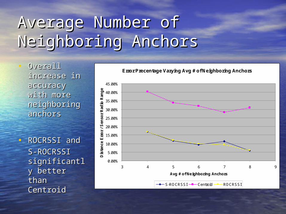
Average Number of Average Number of Neighboring AnchorsNeighboring Anchors• Overall Overall
increase in increase in accuracy with accuracy with more more neighboring neighboring anchorsanchors
• ROCRSSI and ROCRSSI and
S-ROCRSSI S-ROCRSSI significantly significantly better than better than CentroidCentroid
Error Precentage Varying Avg # of Neighboring Anchors
0.00%
5.00%
10.00%
15.00%
20.00%
25.00%
30.00%
35.00%
40.00%
45.00%
3 4 5 6 7 8 9
Avg # of Neighboring Anchors
Dis
tan
ce E
rro
r /
Sen
sor
Rad
io R
ang
e
S-ROCRSSI Centroid ROCRSSI

Varying Anchor Placement Varying Anchor Placement • Simulations on how anchor Simulations on how anchor
topology effects the estimation topology effects the estimation accuracyaccuracy
• Overall decrease in accuracyOverall decrease in accuracy
• S-ROCRSSI outperforms by 20%S-ROCRSSI outperforms by 20%
• Negative Rings Produced 88% Negative Rings Produced 88% of the timeof the time

Result SummaryResult Summary• Lack of improvement to estimation accuracy in many cases. Lack of improvement to estimation accuracy in many cases.
– lack of cases where the information negative rings gave actually lack of cases where the information negative rings gave actually came into use came into use
– Usually the negative rings only reinforced information that the Usually the negative rings only reinforced information that the original ROCRSSI algorithm already knew. original ROCRSSI algorithm already knew.
• Substantial Difference in Unattractive TopologiesSubstantial Difference in Unattractive Topologies– Where the negative rings actually made a substantial difference Where the negative rings actually made a substantial difference
was when anchors were not placed along the perimeter. was when anchors were not placed along the perimeter. – This caused a large amount of negative rings to be produced, This caused a large amount of negative rings to be produced,
giving the S-ROCRSSI algorithm more information and a better giving the S-ROCRSSI algorithm more information and a better location estimate. location estimate.
• Sensor nodes situated outside the perimeter of the anchor Sensor nodes situated outside the perimeter of the anchor nodes, will obtain a more accurate location estimation using nodes, will obtain a more accurate location estimation using the S-ROCRSSI algorithm.the S-ROCRSSI algorithm.
Conclusion / Possible Future Conclusion / Possible Future WorkWork• Despite the lack of improvement in some cases, the project Despite the lack of improvement in some cases, the project
did still demonstrate the effectiveness of the ROCRSSI did still demonstrate the effectiveness of the ROCRSSI algorithm. algorithm. – A 16% estimation error percentage is better than most range-A 16% estimation error percentage is better than most range-
based approaches out there. based approaches out there.
• This project also helped uncover an improving algorithm for This project also helped uncover an improving algorithm for sensor nodes located outside the anchor perimeter sensor nodes located outside the anchor perimeter
• Test algorithms with actual motes in real world conditions.Test algorithms with actual motes in real world conditions.
• The sensor node could alternate which location algorithm it The sensor node could alternate which location algorithm it uses by somehow estimating its general location in respect uses by somehow estimating its general location in respect to the perimeter of the network anchor nodes.to the perimeter of the network anchor nodes.

Questions?Questions?