Raman spectroscopy on amorphous carbon films
9
Raman spectroscopy on amorphous carbon films J. Schwan, S. Ulrich, V. Batori, H. Ehrhardt, and S. R. P. Silva Citation: J. Appl. Phys. 80, 440 (1996); doi: 10.1063/1.362745 View online: http://dx.doi.org/10.1063/1.362745 View Table of Contents: http://jap.aip.org/resource/1/JAPIAU/v80/i1 Published by the American Institute of Physics. Related Articles Density and confinement effects of glass forming m-toluidine in nanoporous Vycor investigated by depolarized dynamic light scattering J. Chem. Phys. 138, 114501 (2013) Effect of temperature and magnetic field on the electrical transport of polyaniline nanofibers J. Appl. Phys. 113, 093707 (2013) Brillouin light scattering spectra as local temperature sensors for thermal magnons and acoustic phonons Appl. Phys. Lett. 102, 082401 (2013) Orientation correlation of p-nitroaniline molecules in acetone solution observed by hyper-Rayleigh scattering J. Chem. Phys. 138, 054502 (2013) Multi-modal characterization of nanogram amounts of a photosensitive polymer Appl. Phys. Lett. 102, 024103 (2013) Additional information on J. Appl. Phys. Journal Homepage: http://jap.aip.org/ Journal Information: http://jap.aip.org/about/about_the_journal Top downloads: http://jap.aip.org/features/most_downloaded Information for Authors: http://jap.aip.org/authors Downloaded 19 Mar 2013 to 128.206.9.138. Redistribution subject to AIP license or copyright; see http://jap.aip.org/about/rights_and_permissions
Transcript of Raman spectroscopy on amorphous carbon films

Raman spectroscopy on amorphous carbon filmsJ. Schwan, S. Ulrich, V. Batori, H. Ehrhardt, and S. R. P. Silva Citation: J. Appl. Phys. 80, 440 (1996); doi: 10.1063/1.362745 View online: http://dx.doi.org/10.1063/1.362745 View Table of Contents: http://jap.aip.org/resource/1/JAPIAU/v80/i1 Published by the American Institute of Physics. Related ArticlesDensity and confinement effects of glass forming m-toluidine in nanoporous Vycor investigated by depolarizeddynamic light scattering J. Chem. Phys. 138, 114501 (2013) Effect of temperature and magnetic field on the electrical transport of polyaniline nanofibers J. Appl. Phys. 113, 093707 (2013) Brillouin light scattering spectra as local temperature sensors for thermal magnons and acoustic phonons Appl. Phys. Lett. 102, 082401 (2013) Orientation correlation of p-nitroaniline molecules in acetone solution observed by hyper-Rayleigh scattering J. Chem. Phys. 138, 054502 (2013) Multi-modal characterization of nanogram amounts of a photosensitive polymer Appl. Phys. Lett. 102, 024103 (2013) Additional information on J. Appl. Phys.Journal Homepage: http://jap.aip.org/ Journal Information: http://jap.aip.org/about/about_the_journal Top downloads: http://jap.aip.org/features/most_downloaded Information for Authors: http://jap.aip.org/authors
Downloaded 19 Mar 2013 to 128.206.9.138. Redistribution subject to AIP license or copyright; see http://jap.aip.org/about/rights_and_permissions
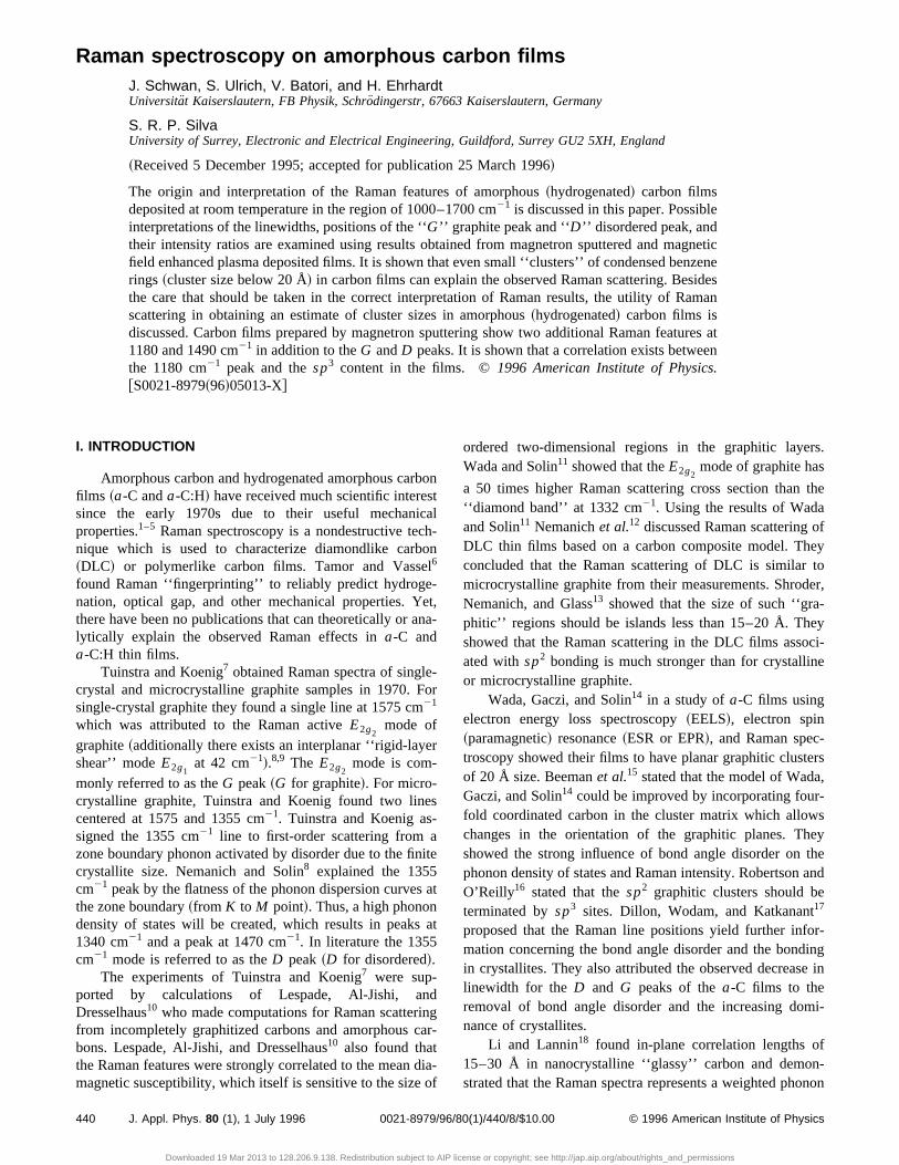
Raman spectroscopy on amorphous carbon filmsJ. Schwan, S. Ulrich, V. Batori, and H. EhrhardtUniversitat Kaiserslautern, FB Physik, Schro¨dingerstr, 67663 Kaiserslautern, Germany
S. R. P. SilvaUniversity of Surrey, Electronic and Electrical Engineering, Guildford, Surrey GU2 5XH, England
~Received 5 December 1995; accepted for publication 25 March 1996!
The origin and interpretation of the Raman features of amorphous~hydrogenated! carbon filmsdeposited at room temperature in the region of 1000–1700 cm21 is discussed in this paper. Possibleinterpretations of the linewidths, positions of the ‘‘G’’ graphite peak and ‘‘D ’’ disordered peak, andtheir intensity ratios are examined using results obtained from magnetron sputtered and magneticfield enhanced plasma deposited films. It is shown that even small ‘‘clusters’’ of condensed benzenerings ~cluster size below 20 Å! in carbon films can explain the observed Raman scattering. Besidesthe care that should be taken in the correct interpretation of Raman results, the utility of Ramanscattering in obtaining an estimate of cluster sizes in amorphous~hydrogenated! carbon films isdiscussed. Carbon films prepared by magnetron sputtering show two additional Raman features at1180 and 1490 cm21 in addition to theG andD peaks. It is shown that a correlation exists betweenthe 1180 cm21 peak and thesp3 content in the films. ©1996 American Institute of Physics.@S0021-8979~96!05013-X#
r
i
eF
-
ni
s.
the
feytoer,
yci-e
rs,
seytheand
r-ingin
i-
-non
I. INTRODUCTION
Amorphous carbon and hydrogenated amorphous cafilms ~a-C anda-C:H! have received much scientific interesince the early 1970s due to their useful mechanproperties.1–5 Raman spectroscopy is a nondestructive tenique which is used to characterize diamondlike carb~DLC! or polymerlike carbon films. Tamor and Vasse6
found Raman ‘‘fingerprinting’’ to reliably predict hydrogenation, optical gap, and other mechanical properties. Ythere have been no publications that can theoretically or alytically explain the observed Raman effects ina-C anda-C:H thin films.
Tuinstra and Koenig7 obtained Raman spectra of singlcrystal and microcrystalline graphite samples in 1970.single-crystal graphite they found a single line at 1575 cm21
which was attributed to the Raman activeE2g2mode of
graphite~additionally there exists an interplanar ‘‘rigid-layeshear’’ modeE2g1
at 42 cm21!.8,9 The E2g2mode is com-
monly referred to as theG peak~G for graphite!. For micro-crystalline graphite, Tuinstra and Koenig found two lincentered at 1575 and 1355 cm21. Tuinstra and Koenig assigned the 1355 cm21 line to first-order scattering from azone boundary phonon activated by disorder due to the ficrystallite size. Nemanich and Solin8 explained the 1355cm21 peak by the flatness of the phonon dispersion curvethe zone boundary~from K toM point!. Thus, a high phonondensity of states will be created, which results in peaks1340 cm21 and a peak at 1470 cm21. In literature the 1355cm21 mode is referred to as theD peak~D for disordered!.
The experiments of Tuinstra and Koenig7 were sup-ported by calculations of Lespade, Al-Jishi, aDresselhaus10 who made computations for Raman scatterfrom incompletely graphitized carbons and amorphous cbons. Lespade, Al-Jishi, and Dresselhaus10 also found thatthe Raman features were strongly correlated to the meanmagnetic susceptibility, which itself is sensitive to the size
440 J. Appl. Phys. 80 (1), 1 July 1996 0021-8979/9
Downloaded 19 Mar 2013 to 128.206.9.138. Redistribution subject to AIP
bonstcalch-onl-et,na-
-or
r
es
nite
s at
at
dngar-
dia-of
ordered two-dimensional regions in the graphitic layerWada and Solin11 showed that theE2g2
mode of graphite has
a 50 times higher Raman scattering cross section than‘‘diamond band’’ at 1332 cm21. Using the results of Wadaand Solin11 Nemanichet al.12 discussed Raman scattering oDLC thin films based on a carbon composite model. Thconcluded that the Raman scattering of DLC is similarmicrocrystalline graphite from their measurements. ShrodNemanich, and Glass13 showed that the size of such ‘‘gra-phitic’’ regions should be islands less than 15–20 Å. Theshowed that the Raman scattering in the DLC films assoated withsp2 bonding is much stronger than for crystallinor microcrystalline graphite.
Wada, Gaczi, and Solin14 in a study ofa-C films usingelectron energy loss spectroscopy~EELS!, electron spin~paramagnetic! resonance~ESR or EPR!, and Raman spec-troscopy showed their films to have planar graphitic clusteof 20 Å size. Beemanet al.15 stated that the model of WadaGaczi, and Solin14 could be improved by incorporating four-fold coordinated carbon in the cluster matrix which allowchanges in the orientation of the graphitic planes. Thshowed the strong influence of bond angle disorder onphonon density of states and Raman intensity. RobertsonO’Reilly16 stated that thesp2 graphitic clusters should beterminated bysp3 sites. Dillon, Wodam, and Katkanant17
proposed that the Raman line positions yield further infomation concerning the bond angle disorder and the bondin crystallites. They also attributed the observed decreaselinewidth for theD andG peaks of thea-C films to theremoval of bond angle disorder and the increasing domnance of crystallites.
Li and Lannin18 found in-plane correlation lengths of15–30 Å in nanocrystalline ‘‘glassy’’ carbon and demonstrated that the Raman spectra represents a weighted pho
6/80(1)/440/8/$10.00 © 1996 American Institute of Physics
license or copyright; see http://jap.aip.org/about/rights_and_permissions

z
n
r
i
ra
n
o-
ed
ansst-
nss,
red
e
xtge-
ofhted
or
t-ere-cted.
-he
density of states~phonon DOS! of low frequency order bycomparison with inelastic neutron scattering data. Ramscattering proved to be most useful in the characterizationcarbon films when theG peak andD peak are distinct in thespectrum. If the carbon system is highly disordered, strocontributions to theG andD peak from the phonon DOSmakes analysis more complicated and demanding.
We report that the observed Raman results of amorpho~hydrogenated! carbon films may be interpreted in terms oan amorphous carbon matrix of threefold and fourfold coodinated carbon atoms in which small regions of a few codensed benzene rings~after Ehrhardtet al.19 and Kleberet al.20 up to five fused benzene rings! are embedded. In thisarticle, it is shown that the so-calledD peak is present incondensed benzene regions even as small as one benring. Thus the nomenclature ‘‘disordered’’ peak is not meaingful for a-C:~H! films. The existence of theD peak isconsidered to be evidence for benzene or condensed benrings in amorphous~hydrogenated! carbon films. We alsoshow that theG peak is not necessarily composed only of thE2g2
mode of graphite but also ofsp2 C5C stretch vibra-tions.
A possible explanation for the position of theG peakand its width will be discussed. The article also tries to uderline the importance of theI D/I G intensity ratio and theGlinewidth. Only by taking both theI D/I G intensity ratio andtheG linewidth can an estimate of the benzene cluster sizin carbon films be obtained.
II. EXPERIMENTAL DETAILS
The films studied in this article were prepared by a manetron and a magnetically field enhanced plasma depositsystem~MEPD!. The films prepared in the unbalanced magnetron source were amorphous carbon films~with hydrogenincorporation lower than 2 at. % as determined by15Nnuclear resonance method! and were deposited by sputteringof a graphite target in an Ar atmosphere at a pressure1.531023 mbar at temperatures below 50 °C. For two diffeent argon ion/neutral carbon ratios of five and ten, carbfilms were deposited at different argon ion energies on crytalline silicon substrates. The films reveal densities up to 3g/cm3 andsp3 ratios of up to 87% as determined by EELSmeasurements.21 Carbon films with such a highsp3 ratio areoften referred to as highly tetrahedral amorphous carbfilms ~ta-C!. The deposition mechanism and other physicproperties are explained in more detail elsewhere.21
The films prepared by a MEPD were performed by ainductively coupled 13.56 MHz acetylene discharge at dferent pressures ranging from 731024 up to 231023 mbar.The a-C:H films were deposited onto a water-coolegrounded substrate holder. These films contain about 29–at. % hydrogen depending on the pressure of the dischaThe applied magnetic field was 500 G at the substrate surfas determined by Hall probe measurements. More detaabout the films and the deposition system are fouelsewhere.22
The Raman measurements were carried out on a Ramapparatus using the 515 nm line of an Ar ion laser focused
J. Appl. Phys., Vol. 80, No. 1, 1 July 1996
Downloaded 19 Mar 2013 to 128.206.9.138. Redistribution subject to AIP
anof
ng
usfr-n-
zenen-
ene
e
-
es
g-ion-
of-ons-.1
onal
nf-
d32ge.ceilsd
anto
2 mm2. The laser power was 500 mW and the spectral reslution of the apparatus was 8 cm21. Typical data acquisitiontimes were in the range of 25 min. The spectra were recordin the range of 80–3000 cm21 in order to allow reliablefitting ~Table I!. In the case of the MEPD depositeda-C:Hfilms the Raman spectra have been fitted by two Gaussiallowing all the fit parameters to vary. In the case of filmdeposited by magnetron sputtering combined with ion plaing ~MS/IP! most of the films could not be fitted by twoGaussians~except those deposited at low Ar plating energy!.To obtain a good fit it was necessary to use four Gaussia~Table II!. Here all the fit parameters such as linewidthpositions, and areas were allowed to vary@Fig. 1~b!#. OtherRaman data has been taken from the literature. Figure 1~b!shows Raman features which are due to a highly disordecarbon structure.
III. RESULTS AND DISCUSSION
Tuinstra and Koenig7 found that the Raman intensity ofthe I D/I G is inversely proportional to the graphite crystallizsizeLa :
1
La}I 1355I 1575
5I DI G, ~1!
whereLa is the graphite crystallite size as determined byray. Equation~1!, although valid for graphite, has so far nobeen proven to be valid for amorphous carbon and hydronated amorphous carbon films. Tamoret al.30 showed bycomparison with optical measurements that Eq.~1! cannot beapplied to amorphous carbon. Therefore the analogyamorphous carbon to graphite is not straightforward. Knigand White28 presented data which when extrapolated showan I D/I G ratio of four for a graphitic cluster size of 10 Å.Thus, the experiment places an upper limit of 10–20 Å f
TABLE I. Before fitting of the carbon films prepared by magnetron sputering the background of the Raman spectrum has to be subtracted. Thfore four Gaussians centered at the given wavelengths had to be subtraThe original Raman spectrum of one film can be seen in Fig. 1~a! togetherwith the background spectrum. Figure 1~b! shows the resulting Raman spectrum after the subtraction of the background together with the final fit in tdiscussed region between 1000 and 1700 cm21.
Background peaks~cm21! Assigned to:
800 Hydrogen free carbon structure~Ref. 6!
1950 Second-order combination scattering of twomain structures at 550 and 1550 cm21
~Ref. 23!
2420 Two phonon excitation from the 1100 to1300 cm21 region ~Ref. 8!
2930 Combination of the zone center 1580 cm21
mode and the zone boundary 1355 cm21
mode~Ref. 24!or combination of the density of statesfeature at 1620 cm21 and the zone boundary1355 cm21 mode~Ref. 8!
441Schwan et al.
license or copyright; see http://jap.aip.org/about/rights_and_permissions

a
s
re
n
t-
t
inr
oa
eenceures
tng
the graphitic cluster size in amorphous carbon films. Susmall cluster sizes evoke the question of the origin of theDandG peak in amorphous carbons.
A. G peak and D peak in amorphous (hydrogenated)carbon films
Consider theG peak. Single benzene rings exhibit a Rman peak at 1588 cm21 @Fig. 2~a!#. This feature is valid forbenzene, all aromatic rings, and condensed benzene ringpossible contribution to theG peak therefore may arise fromthe C5C sp2 stretch vibrations of olefinic or conjugated cabon ‘‘chains’’ ~or first-order scattering from features in thdensity of states of a graphite network! at about 1620 cm21,too. Thus, the existence of aG peak in the Raman spectrumdoes not necessarily prove that thea-C film consists only ofgraphite or fused benzene rings. TheG peak might as wellhave its origin in olefinic chains in the carbon film. Benzerings show a further Raman feature at 1486 cm21 @Fig.2~b!#.29 A peak centered at 1490 cm21 can be attributed tosemicircle stretching of carbon atoms in single aromarings or fused aromatic rings.29,31Another possible explanation for the peak at 1470 cm21 ~in finite-size crystals ofgraphite! was given by Nemanich and Solin,8 who attributedthis peak to contributions from the phonon DOS.
In the case of theD peak, interaction force constaneffects have to be considered.29 Normally, the simple valenceforce field is used to calculate vibration frequencies. If twor more oscillators in a molecule or solid are distorted froequilibrium, they may be able to affect each other’s restorforces to some extent, due to changes in the electronic stture. A more general valence force field considers the torestoring force on one oscillator to be equal to a force cstant times its own distortion plus a second force const
TABLE II. Raman features in the range between 1000 and 1700 cm21 arelisted. Possible interpretations of these features are given. The Ramantures denoted by~* ! are used for fitting.
Raman featurecm21 Possible interpretation
1180 ~* ! Nanocrystalline diamond~Ref. 25!hexagonal diamond~Refs. 12, 26, and 27! orsp
3-rich phase~Refs. 12 and 13!
1305 Hexagonal diamond~Refs. 27 and 28!
1332 Cubic diamond
1350 ~* ! D peak of microcrystalline graphite~Ref. 6! oralternating ring stretch vibration in benzeneor condensed benzene rings
1490 ~* ! Semicircle ring stretch vibration of benzeneor condensed benzene rings orin the case ofa-C:H contributions of C–Hvibrations at 1500 cm21 ~Ref. 29!or contributions from the phonon density ofstates in finite-size crystals of graphite~Ref. 8!
1580 ~* ! G peak of graphite~Ref. 6! orsp2 stretch vibration in benzene or condensedbenzene ringsor sp2 stretch vibration of olefinic/conjugatedchains
442 J. Appl. Phys., Vol. 80, No. 1, 1 July 1996
Downloaded 19 Mar 2013 to 128.206.9.138. Redistribution subject to AIP
ch
-
. A
-
e
ic
omguc-taln-nt
fea-
FIG. 1. ~a! Original Raman spectrum of MS/IP depositeda-C and its back-ground from Table I,~b! Raman spectrum of~a! subtracted by the back-ground fit to the data for MS/IP depositeda-C. Gaussian line shapes havbeen used as Lorentzian line shapes would only be expected in the presof crystalline inclusions in the amorphous carbon films. The Raman featare expected to consist of multiple lines as shown in Fig. 2~d! which is alsoan indication for Gaussian line shapes.
FIG. 2. ~a! Carbon stretch vibrations in benzene centered at 1588 cm21, ~b!semicircle stretch vibrations in benzene at 1486 cm21, ~c! alternating ringstretch in benzene centered at 1311 cm21 due to interaction force constaneffects~Ref. 29!, ~d! superposition of different Raman active modes leadito broader effective linewidths
Schwan et al.
license or copyright; see http://jap.aip.org/about/rights_and_permissions
f
-
f
,
t
o
n
e
ve
so
entsultaree-ts.c-
ad-he
ar
heore
s in
l
he
ic
erere
times the distortion of a second oscillator. The second forconstant is called the interaction force constant and caneither positive or negative. The alternating ring stretchbenzene is illustrated in Fig. 2~c!. During this vibration, theelectronic structure changes and approaches the Kekule bzene structure where electrons partially slip away frostretched bonds into contracted bonds. This leads to thequency of the alternating ring stretch vibration of benzene1311 cm21, much lower than that predicted from the simplvalence force field model~1700 cm21!. For a more detaileddiscussion see Colthupet al.29 The existence of a peak centered at about 1350 cm21 proves the existence of aromatic obenzene clusters incorporated in the amorphous~hydroge-nated! carbon films. Nevertheless, if a Raman spectrum ocarbon film reveals a peak at 1350 cm21 this peak may aswell have its origin in the phonon DOS contribution ohighly disordered graphitic structures8 ~see also Table II!.
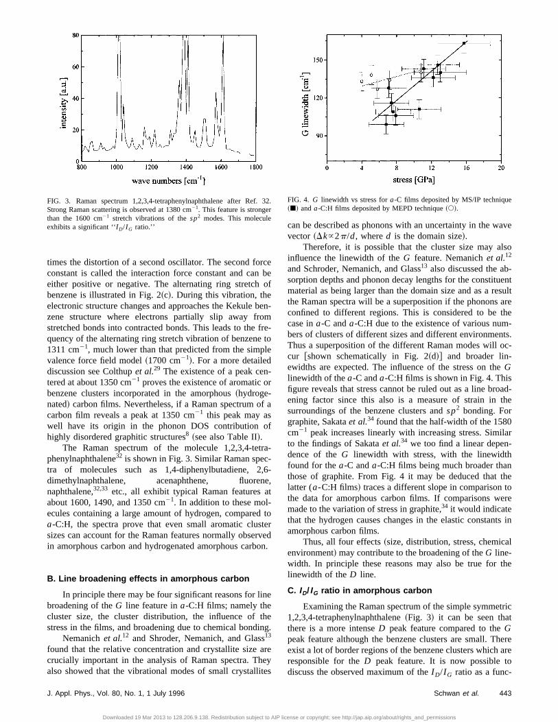
The Raman spectrum of the molecule 1,2,3,4-tetrphenylnaphthalene32 is shown in Fig. 3. Similar Raman spectra of molecules such as 1,4-diphenylbutadiene, 2dimethylnaphthalene, acenaphthene, fluorennaphthalene,32,33 etc., all exhibit typical Raman features aabout 1600, 1490, and 1350 cm21. In addition to these mol-ecules containing a large amount of hydrogen, compareda-C:H, the spectra prove that even small aromatic clussizes can account for the Raman features normally obserin amorphous carbon and hydrogenated amorphous carb
B. Line broadening effects in amorphous carbon
In principle there may be four significant reasons for linbroadening of theG line feature ina-C:H films; namely thecluster size, the cluster distribution, the influence of thstress in the films, and broadening due to chemical bondi
Nemanichet al.12 and Shroder, Nemanich, and Glass13
found that the relative concentration and crystallite size acrucially important in the analysis of Raman spectra. Thalso showed that the vibrational modes of small crystallit
FIG. 3. Raman spectrum 1,2,3,4-tetraphenylnaphthalene after Ref.Strong Raman scattering is observed at 1380 cm21. This feature is strongerthan the 1600 cm21 stretch vibrations of thesp2 modes. This moleculeexhibits a significant ‘‘I D/I G ratio.’’
J. Appl. Phys., Vol. 80, No. 1, 1 July 1996
Downloaded 19 Mar 2013 to 128.206.9.138. Redistribution subject to AIP
cebeof
en-mre-toe
r
a
f
a--6-e,t
toervedn.
e
eg.
reyes
can be described as phonons with an uncertainty in the wavector ~Dk}2p/d, whered is the domain size!.
Therefore, it is possible that the cluster size may alinfluence the linewidth of theG feature. Nemanichet al.12
and Schroder, Nemanich, and Glass13 also discussed the ab-sorption depths and phonon decay lengths for the constitumaterial as being larger than the domain size and as a rethe Raman spectra will be a superposition if the phononsconfined to different regions. This is considered to be thcase ina-C anda-C:H due to the existence of various numbers of clusters of different sizes and different environmenThus a superposition of the different Raman modes will ocur @shown schematically in Fig. 2~d!# and broader lin-ewidths are expected. The influence of the stress on theGlinewidth of thea-C anda-C:H films is shown in Fig. 4. Thisfigure reveals that stress cannot be ruled out as a line broening factor since this also is a measure of strain in tsurroundings of the benzene clusters andsp2 bonding. Forgraphite, Sakataet al.34 found that the half-width of the 1580cm21 peak increases linearly with increasing stress. Similto the findings of Sakataet al.34 we too find a linear depen-dence of theG linewidth with stress, with the linewidthfound for thea-C anda-C:H films being much broader thanthose of graphite. From Fig. 4 it may be deduced that tlatter (a-C:H films! traces a different slope in comparison tthe data for amorphous carbon films. If comparisons wemade to the variation of stress in graphite,34 it would indicatethat the hydrogen causes changes in the elastic constantamorphous carbon films.
Thus, all four effects~size, distribution, stress, chemicaenvironment! may contribute to the broadening of theG line-width. In principle these reasons may also be true for tlinewidth of theD line.
C. ID/IG ratio in amorphous carbon
Examining the Raman spectrum of the simple symmetr1,2,3,4-tetraphenylnaphthalene~Fig. 3! it can be seen thatthere is a more intenseD peak feature compared to theGpeak feature although the benzene clusters are small. Thexist a lot of border regions of the benzene clusters which aresponsible for theD peak feature. It is now possible todiscuss the observed maximum of theI D/I G ratio as a func-
32.FIG. 4. G linewidth vs stress fora-C films deposited by MS/IP technique~j! anda-C:H films deposited by MEPD technique~s!.
443Schwan et al.
license or copyright; see http://jap.aip.org/about/rights_and_permissions

m
d
s
l.
Åree,
end
g
a
n
-
dt
of
hat
ms
as
nrs
ut
r
tion of the cluster sizes in thea-C anda-C:H films shown inFig. 5. Tuinstra and Koenig7 did not find aD peak in idealgraphite. If this ideal graphite is now assumed to be moand more disturbed bysp3 bonded carbon, theD peak willdevelop and rise in magnitude in the Raman spectrum. Whthe material is composed entirely ofsp3 bonded carbon~and/or olefinic chains connected bysp3 bonded carbon! theD peak should not be detected in this model because thexist no benzene clusters that gave rise to the disorderegions which are responsible for theD peak, i.e., in a com-pletelysp3 network theI D/I G ratio will tend to zero. This isobserved by Praweret al.37 in ta-C films prepared by massselected ion beams havingsp3 ratios of about 80%. Accord-ing to the model proposed theI D/I G ratio will go through amaximum which is dependent on the cluster sizes and disbutions. Using the extrapolation of Knight and White28 andusing the experimental results that a maximum to the ratiofour was found, the optimum cluster size for a maximuI D/I G ratio is estimated to be 10 Å. But still theI D/I G ratiois generally a measure for the zone edges or bordphonons38 of the clusters~which depend on cluster sizes andistributions!.
Tamor et al.30 concluded from their measurements thathe I D/I G ratio is not a useful indicator of graphitic clusterin amorphous carbon films. The Raman results so far confithe cluster model of Wada, Gaczi, and Solin14 and Robertsonand O’Reilly.16 But Raman spectroscopy does not necessily prove the existence of large cluster sizes that are dcussed in these models. Ehrhardtet al.19 and Kleberet al.20
found cluster sizes of up to 5 fused benzene rings in tha-C:H films as derived from ESR.
Since theG linewidth is partly determined by the do-main or size of the~fused! benzene rings, theI D/I G ratio isplotted versusG linewidth in Fig. 5 for variousa-C and
FIG. 5. I D/I G ratio vsG linewidth for a-C:H h ~Ref. 6!, MEPD depositeda-C:H D, a-C:H deposited by magnetic confinement, ~Ref. 35!, a-C:Hdeposited by Mariottoet al.L ~Ref. 36!, sputtereda-C d ~Ref. 6!, i -C orta-C j ~Ref. 6!, MS/IP depositedta-C D, various graphite and other car-bons by Knightet al.l ~Ref. 28!. We propose that theD peak for carbonfilms with aG linewidth smaller than 45 cm21 is dominated by microcrys-talline graphite inclusions whereas theD peak fora-C~:H! films with Glinewidths broader than 45 cm21 is mostly dominated by small aromaticclusters with cluster sizes lower than 10 Å.
444 J. Appl. Phys., Vol. 80, No. 1, 1 July 1996
Downloaded 19 Mar 2013 to 128.206.9.138. Redistribution subject to AIP
re
en
erered
tri-
of
er
t
rm
ar-is-
eir
a-C:H films also using the data set of Tamor and Vasse6
Further data of Knight and White,28 Silva et al.35 and Mari-otto et al.36 are used. All named authors used the 5145excitation line, so that their results can be compared. Hethe difference between graphite, microcrystalline graphitchemical vapor depositeda-C:H, sputtereda-C, ta-C ~tetra-hedrally bonded amorphous carbon! deposited by laser abla-tion, and MEPD depositeda-C:H films can be clearly seen.The line through these points is for leading the eye. Thcarbon films deposited by MS/IP will be discussed later. Ithe case of microcrystalline graphite the small linewidth anlow I D/I G ratio are good indicators for the crystallinity of thesamples. As theG linewidth gets broader there is a maxi-mum in theI D/I G ratio of four. In order to get a better surveythe graphitic cluster sizes, those from Tuinstra and Koeni7
and Knight and White28 are also included on theI D/I G axisand the bottom line of theG-linewidth axis.
When theG linewidth for amorphous carbon films andamorphous hydrogenated carbon films increases abovevalue of 50 cm21 it is observed~Fig. 5! that theI D/I G ratiodecreases. As discussed previously@see Eq.~1!#, if the Glinewidth increases beyond 50 cm21, it results in a reductionin the I D/I G ratio. From the work of Tuinstra and Koenig7
we see that the maximum in theI D/I G peak value of 4 cor-responds to an effective graphitic cluster size for carbofilms of 10 Å. Therefore, when theG linewidth increasesbeyond 50 cm21, the resulting decrease in theI D/I G ratiowould be indicative of a cluster size smaller than 10 Å according to Eq.~1!. This result is confirmed by the extrapo-lated values for microcrystalline graphite by Knight anWhite.28 The data points in Fig. 5 lead to the conclusion thathe fused benzene clusters ina-C:H deposited by chemicalvapor deposition are larger than in sputtereda-C. Recenttransmission electron microscope results by Daviset al.40 ona-C:H superlattice structures show there to be no evidenceclusters greater than 5 Å in rf plasma depositeda-C:H films.The Raman data for amorphous sputtered carbon reveal tonly a minor fraction of ordered sixfold rings exists.41 Ifthere were larger clusters inside the sputtered carbon filtheG linewidth should be smaller and theI D/I G ratio shouldbe higher. In the case of ion-carbon~i -C! or highly tetrahe-dral amorphous carbon~ta-C! the I D/I G ratio together withtheG linewidth indicates the presence of little benzene~clus-ter! inclusions within the films. Thea-C:H films depositedby the MEPD also possess lowI D/I G ratio and broadGlinewidth.22,37This is also an indication for small clusters inthe films. The optical gap of these films is quite high~2 eV!which also reinforces the interpretation of cluster sizesderived from theI D/I G ratio andG linewidth.
The ta-C films deposited by the unbalanced magnetrodeviate from the data of the other carbon films. In the authoopinion the high stress in the films~up to 20 GPa measuredby the bending beam method using Stoney’s equation! isresponsible for the broadG linewidth. In these films theI D/I G ratio alone indicates an effective cluster size of abo10 Å. Thus, only the knowledge about both theI D/I G ratioand theG linewidth allows a rough estimate of the clustesize in amorphous~hydrogenated! carbon films. Having in-
Schwan et al.
license or copyright; see http://jap.aip.org/about/rights_and_permissions
u
b
t
b
g
hy-
at
ed
formation only about theI D/I G ratio does not give reliableinformation with regard to the cluster sizes in carbon films
D. Positions of the G and D peak of amorphous(hydrogenated) carbon films
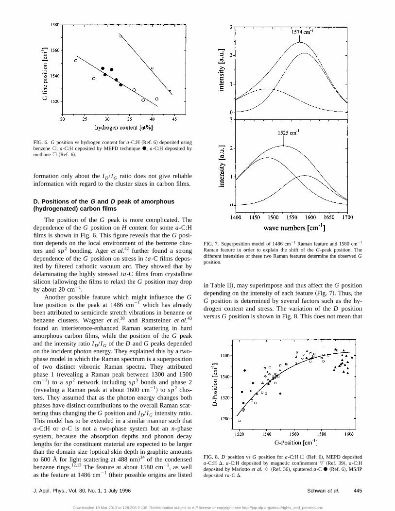
The position of theG peak is more complicated. Thedependence of theG position onH content for somea-C:Hfilms is shown in Fig. 6. This figure reveals that theG posi-tion depends on the local environment of the benzene clters andsp2 bonding. Ageret al.42 further found a strongdependence of theG position on stress inta-C films depos-ited by filtered cathodic vacuum arc. They showed thatdelaminating the highly stressedta-C films from crystallinesilicon ~allowing the films to relax! theG position may dropby about 20 cm21.
Another possible feature which might influence theGline position is the peak at 1486 cm21 which has alreadybeen attributed to semicircle stretch vibrations in benzenebenzene clusters. Wagneret al.38 and Ramsteineret al.43
found an interference-enhanced Raman scattering in hamorphous carbon films, while the position of theG peakand the intensity ratioI D/I G of theD andG peaks dependedon the incident photon energy. They explained this by a twphase model in which the Raman spectrum is a superposiof two distinct vibronic Raman spectra. They attributephase 1~revealing a Raman peak between 1300 and 15cm21! to a sp2 network includingsp3 bonds and phase 2~revealing a Raman peak at about 1600 cm21! to sp2 clus-ters. They assumed that as the photon energy changesphases have distinct contributions to the overall Raman sctering thus changing theG position andI D/I G intensity ratio.This model has to be extended in a similar manner such ta-C:H or a-C is not a two-phase system but ann-phasesystem, because the absorption depths and phonon delengths for the constituent material are expected to be larthan the domain size~optical skin depth in graphite amountsto 600 Å for light scattering at 488 nm!34 of the condensedbenzene rings.12,13 The feature at about 1580 cm21, as wellas the feature at 1486 cm21 ~their possible origins are listed
FIG. 6. G position vs hydrogen content fora-C:H ~Ref. 6! deposited usingbenzenes, a-C:H deposited by MEPD techniqued, a-C:H deposited bymethaneh ~Ref. 6!.
J. Appl. Phys., Vol. 80, No. 1, 1 July 1996
Downloaded 19 Mar 2013 to 128.206.9.138. Redistribution subject to AIP
.
s-
y
or
ard
o-iond00
othat-
hat
cayer
in Table II!, may superimpose and thus affect theG positiondepending on the intensity of each feature~Fig. 7!. Thus, theG position is determined by several factors such as thedrogen content and stress. The variation of theD positionversusG position is shown in Fig. 8. This does not mean th
FIG. 7. Superposition model of 1486 cm21 Raman feature and 1580 cm21
Raman feature in order to explain the shift of theG-peak position. Thedifferent intensities of these two Raman features determine the observGposition.
FIG. 8. D position vsG position fora-C:H h ~Ref. 6!, MEPD depositeda-C:H D, a-C:H deposited by magnetic confinement, ~Ref. 39!, a-C:Hdeposited by Mariottoet al.L ~Ref. 36!, sputtereda-C d ~Ref. 6!, MS/IPdepositedta-C D.
445Schwan et al.
license or copyright; see http://jap.aip.org/about/rights_and_permissions
t
n
r
w
h
a
ke
Ro
h
rIt
beed’’be
car-to bes a
ionssing-
llycen-hedis-toessalt oftion,g at
onhek.650
sge-ank
g. B
hnol.
the D position is a function of theG position. Figure 8shows that in principle the same arguments that hold forG position may also hold for theD position. It illustrates thatfor example stress in the films shifts theG position as well asthe D position. Figure 8 also reveals that there is a strocorrelation between theG position andD position on thetype of the films which was already shown by Tamoret al.6
E. Raman feature at 1180 cm 21 for carbon filmsdeposited by the magnetron
In the films deposited by the MS/IP technique we wenot able to obtain good fits just by considering theG andDpeaks. Acceptable fits could only be reached by adding textra peaks at approximately 1180 and 1490 cm21. The peakat 1490 cm21 has already been discussed. Together with t1180 cm21 peak a rather small and narrow peak at 130cm21 is observed for films with highsp3 content. The peakat 1180 cm21 is very broad with a bandwidth of 200 cm21.One of the components that causes such a broadening ishigh compressive stress present in the films.
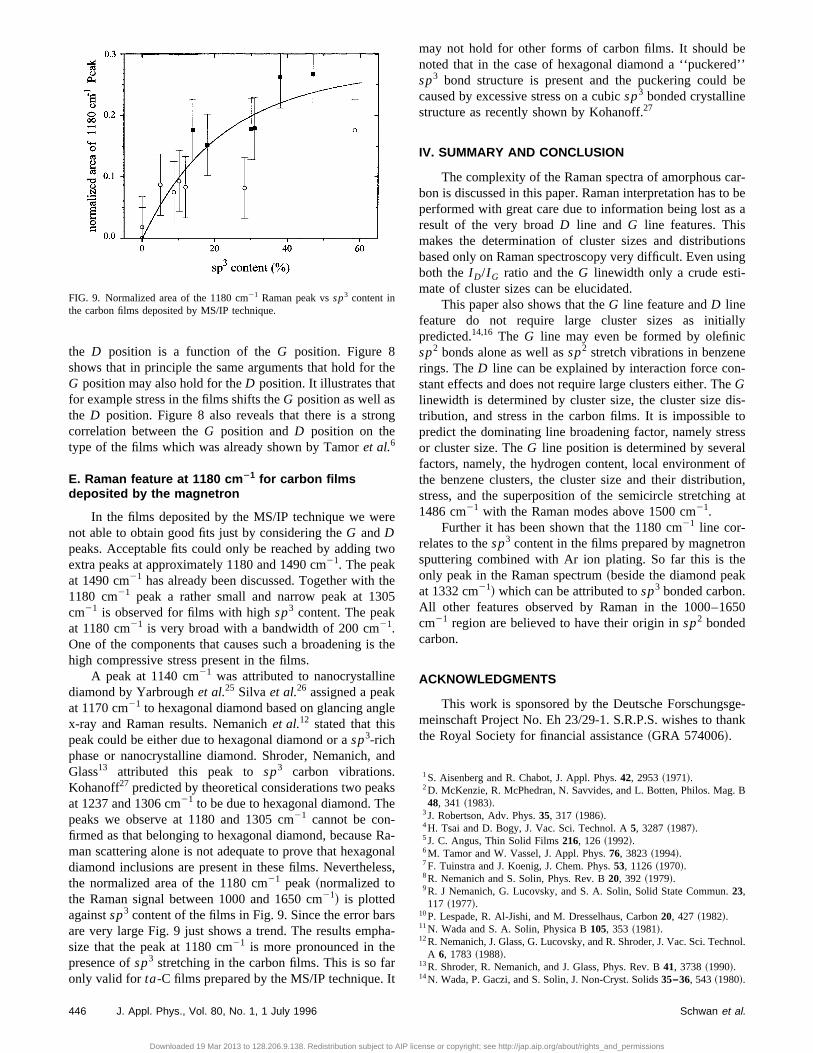
A peak at 1140 cm21 was attributed to nanocrystallinediamond by Yarbroughet al.25 Silva et al.26 assigned a peakat 1170 cm21 to hexagonal diamond based on glancing angx-ray and Raman results. Nemanichet al.12 stated that thispeak could be either due to hexagonal diamond or asp3-richphase or nanocrystalline diamond. Shroder, Nemanich,Glass13 attributed this peak tosp3 carbon vibrations.Kohanoff27 predicted by theoretical considerations two peaat 1237 and 1306 cm21 to be due to hexagonal diamond. Thpeaks we observe at 1180 and 1305 cm21 cannot be con-firmed as that belonging to hexagonal diamond, becauseman scattering alone is not adequate to prove that hexagdiamond inclusions are present in these films. Neverthelethe normalized area of the 1180 cm21 peak ~normalized tothe Raman signal between 1000 and 1650 cm21! is plottedagainstsp3 content of the films in Fig. 9. Since the error barare very large Fig. 9 just shows a trend. The results empsize that the peak at 1180 cm21 is more pronounced in thepresence ofsp3 stretching in the carbon films. This is so faonly valid for ta-C films prepared by the MS/IP technique.
FIG. 9. Normalized area of the 1180 cm21 Raman peak vssp3 content inthe carbon films deposited by MS/IP technique.
446 J. Appl. Phys., Vol. 80, No. 1, 1 July 1996
Downloaded 19 Mar 2013 to 128.206.9.138. Redistribution subject to AIP
he
g
e
o
e5
the
le
nd
s
a-nalss,
sa-
may not hold for other forms of carbon films. It shouldnoted that in the case of hexagonal diamond a ‘‘puckersp3 bond structure is present and the puckering couldcaused by excessive stress on a cubicsp3 bonded crystallinestructure as recently shown by Kohanoff.27
IV. SUMMARY AND CONCLUSION
The complexity of the Raman spectra of amorphousbon is discussed in this paper. Raman interpretation hasperformed with great care due to information being lost aresult of the very broadD line andG line features. Thismakes the determination of cluster sizes and distributbased only on Raman spectroscopy very difficult. Even uboth theI D/I G ratio and theG linewidth only a crude estimate of cluster sizes can be elucidated.
This paper also shows that theG line feature andD linefeature do not require large cluster sizes as initiapredicted.14,16 The G line may even be formed by olefinisp2 bonds alone as well assp2 stretch vibrations in benzenrings. TheD line can be explained by interaction force costant effects and does not require large clusters either. TGlinewidth is determined by cluster size, the cluster sizetribution, and stress in the carbon films. It is impossiblepredict the dominating line broadening factor, namely stror cluster size. TheG line position is determined by severfactors, namely, the hydrogen content, local environmenthe benzene clusters, the cluster size and their distribustress, and the superposition of the semicircle stretchin1486 cm21 with the Raman modes above 1500 cm21.
Further it has been shown that the 1180 cm21 line cor-relates to thesp3 content in the films prepared by magnetrsputtering combined with Ar ion plating. So far this is tonly peak in the Raman spectrum~beside the diamond peaat 1332 cm21! which can be attributed tosp3 bonded carbonAll other features observed by Raman in the 1000–1cm21 region are believed to have their origin insp2 bondedcarbon.
ACKNOWLEDGMENTS
This work is sponsored by the Deutsche Forschungmeinschaft Project No. Eh 23/29-1. S.R.P.S. wishes to ththe Royal Society for financial assistance~GRA 574006!.
1S. Aisenberg and R. Chabot, J. Appl. Phys.42, 2953~1971!.2D. McKenzie, R. McPhedran, N. Savvides, and L. Botten, Philos. Ma48, 341 ~1983!.
3J. Robertson, Adv. Phys.35, 317 ~1986!.4H. Tsai and D. Bogy, J. Vac. Sci. Technol. A5, 3287~1987!.5J. C. Angus, Thin Solid Films216, 126 ~1992!.6M. Tamor and W. Vassel, J. Appl. Phys.76, 3823~1994!.7F. Tuinstra and J. Koenig, J. Chem. Phys.53, 1126~1970!.8R. Nemanich and S. Solin, Phys. Rev. B20, 392 ~1979!.9R. J Nemanich, G. Lucovsky, and S. A. Solin, Solid State Commun.23,117 ~1977!.
10P. Lespade, R. Al-Jishi, and M. Dresselhaus, Carbon20, 427 ~1982!.11N. Wada and S. A. Solin, Physica B105, 353 ~1981!.12R. Nemanich, J. Glass, G. Lucovsky, and R. Shroder, J. Vac. Sci. TecA 6, 1783~1988!.
13R. Shroder, R. Nemanich, and J. Glass, Phys. Rev. B41, 3738~1990!.14N. Wada, P. Gaczi, and S. Solin, J. Non-Cryst. Solids35–36, 543~1980!.
Schwan et al.
license or copyright; see http://jap.aip.org/about/rights_and_permissions

n
v
e
5R,
pl.
,
.
.
.
15D. Beeman, J. Silverman, R. Lynds, and M. Anderson, Phys. Rev. B30,870 ~1984!.
16J. Robertson and E. O’Reilly, Phys. Rev. B35, 2946~1986!.17R. Dillon, J. Wodam, and V. Katkanant, Phys. Rev. B29, 3482~1984!.18F. Li and J. Lannin, Appl. Phys. Lett.61, 2116~1992!.19H. Ehrhardt, R. Kleber, A. Kru¨ger, W. Dworschak, K. Jung, I. Mu¨hling, F.Engelke, and H. Metz, Diamond Relat. Mater.1, 316 ~1992!.
20R. Kleber, K. Jung, H. Ehrhardt, I. Mu¨hling, K. Breuer, H. Metz, and F.Engelke, Thin Solid Films205, 274 ~1991!.
21J. Schwan, S. Ulrich, H. Roth, K. Jung, H. Ehrhardt, R. Samlenski,Brenn, and S. R. P. Silva, J. Appl. Phys.79, 1416~1996!.
22J. Schwan, S. Ulrich, K. Jung, H. Ehrhardt, R. Samlenski, and R. BreDiamond Relat. Mater.4, 304 ~1995!.
23W. S. Bacsa, J. S. Lannin, D. L. Pappas, and J. J. Cuomo, Phys. Re47, 10931~1993!.
24R. B. Wright, R. Varma, and D. M. Gruen, J. Nucl. Mater.63, 415~1976!.25W. Yarbrough and R. Rey, inDiamond and Related Materials, edited byA. Badzian, M. Geis, and G. Johnson~Materials Resource Society, Pitts-burgh, PA, 1988!, extended abstract Vol. EA-15, p. 33.
26S. R. P. Silva, G. Amaratunga, E. Salje, and K. Knowles, J. Mater. R29, 4962~1994!.
27J. Kohanoff, Comput. Mater. Sci.2, 221 ~1994!.28D. Knight and W. White, J. Mater. Res.4, 385 ~1989!.29N. Colthup, L. Daly, and S. Wiberley,Introduction to Infrared and RamanSpectroscopy~Academic, New York 1975!.
J. Appl. Phys., Vol. 80, No. 1, 1 July 1996
Downloaded 19 Mar 2013 to 128.206.9.138. Redistribution subject to AIP
R.
n,
. B
s.
30M. Tamor, J. Haire, C. Wu, and K. Hass, Appl. Phys. Lett.54, 123~1989!.31M. Tamor, C. Wu, R. Carter, and N. Lindsay, Appl. Phys. Lett.55, 1388
~1989!.32Sadtler Research Laboratories, Standard Raman Spectra, Vol. 9, 3553316 Spring Garden Street, Philadelphia, PA 19104.
33F. R. Dollish, W. G. Fateley, and F. F. Bentley,Characteristic RamanFrequencies of Organic Compounds~Wiley, New York 1974!.
34H. Sakata, G. Dresselhaus, M. S. Dresselhaus, and M. Endo, J. ApPhys.63, 2769~1988!.
35S. R. P. Silva, B. Rafferty, G. A. J. Amaratunga, L. M. Brown, J. Schwanand D. Franceschini, Diamond Relat. Mater.5, 401 ~1996!.
36G. Mariotto, F. Freire, and C. Achete, Thin Solid Films241, 255 ~1994!.37S. Prawer, K. W. Nugent, Y. Lifshitz, G. D. Lempert, E. Grossmann, JKulik, I. Avigal, and R. Kalish, Diamond Relat. Mater.~in press!.
38J. Wagner, M. Ramsteiner, C. Wild, and P. Koidl, Phys. Rev. B40, 1817~1989!.
39S. R. P. Silva, B. Rafferty, G. A. J. Amaratunga, J. Robertson, L. MBrown, J. Schwan, G. Mariotto, and D. Franceschini~unpublished!.
40C. A. Davis, S. R. P. Silva, K. M. Knowles, G. A. J. Amaratunga, and MW. Stobbs, Phys. Rev. Lett.75, 4258~1995!.
41F. Li and J. Lannin, Phys. Rev. Lett.65, 1905~1990!.42J. Ager III, S. Anders, A. Anders, and I. Brown, Appl. Phys. Lett.66,3444 ~1995!.
43M. Ramsteiner, J. Wagner, C. Wild, and P. Koidl, J. Appl. Phys.62, 729~1987!.
447Schwan et al.
license or copyright; see http://jap.aip.org/about/rights_and_permissions