Railway Infrastructure Management - System...
51
Railway Infrastructure Management - System Engineering and Requirement Management Master of Science Thesis by Anlin Zhu TRITA AVE 2017:66 ISSN 1651-7660 ISRN KTH/AVE/RTM-17/66 ISBN 978-91-7729-532-7 ________________________________________________________ Postal Address KTH Royal Institute of Technology Aeronautical and Vehicle Engineering Rail Vehicles SE-100 44 Stockholm Visiting Address Teknikringen 8 Stockholm Telephone +46 70 652 2441 E-mail [email protected]
Transcript of Railway Infrastructure Management - System...

Railway Infrastructure Management -
System Engineering and Requirement Management
Master of Science Thesis
by
Anlin Zhu
TRITA AVE 2017:66
ISSN 1651-7660
ISRN KTH/AVE/RTM-17/66
ISBN 978-91-7729-532-7
________________________________________________________
Postal Address
KTH Royal Institute of Technology
Aeronautical and Vehicle Engineering
Rail Vehicles
SE-100 44 Stockholm
Visiting Address
Teknikringen 8
Stockholm
Telephone
+46 70 652 2441


I
Sammanfattning Rail Control Solutions (RCS) är en del av Bombardier Transportation, som syftar till att optimera flödet av tåg. OPTIFLO är ett nytt programspaket inom RCS, som erbjuder tjänster och lösningar för att hantera utmaningar inom modern järnvägsinfrastruktur världen över. Infrastrucutre Management (IM) Service är en viktig delmodul under OPTIFLO, som utför övervakning och diagnostiska funktioner för varje påverkat system eller komponent i järnvägssignalsystem för att kontinuerligt förbättra säkerhet, tillförlitlighet och tillgänglighet. Kravhantering är ett viktigt steg när man arbetar med tekniska problem. Det här mastersprojektet är inriktat på tre moduler inom järnvägssignalområdet: systemnivå Infrastructure Management, underhållssystem för Maintenance and Diagnostic Centre (MDC) och delsystemnivå Remote Sensor Unit (RSU). För varje del har kravhantering implementerats, med hänvisning till CENELEC-standarder vid behov. Arbetet har utgått från utkast till kravspecifikation för IM och identifierat kraven för diagnostik och prestanda i varje delsystem. Både kopplingar mellan kraven i olika moduler och kopplingar mellan kraven och deras testfall är byggda i systemet DOORS för att realisera verifiering och validering i en systemteknisk process. Slutligen släpps standarddokumentationen "Systemkrav Specifikation" för de moduler som behandlar i detta arbete. Nyckelord: Järnvägssignalering, OPTIFLO, Infrastrucutre Management, Systemteknik, Krav

II
Abstract Rail Control Solutions (RCS) is one division of Bombardier Transportation, aimed at optimising flow of trains. OPTIFLO is a new solution package within RCS, providing services and solutions to address challenges in modern railway infrastructures worldwide. Infrastructure Management (IM) Service is a significant sub-module under OPTIFLO, performing monitoring and diagnostic functionalities for each impacted system or component in railway signalling systems to continuously improve safety, reliability and availability. Requirement management is a significant stage while dealing with engineering problems. In this master thesis project, three modules in railway signalling scope are focused, including system level Infrastructure Management, sub-system level Maintenance and Diagnostic Centre (MDC) and sub-system level Remote Sensor Unit (RSU). For each part, requirement managements have been implemented, referring to CENELEC standards where necessary. The work starts with the draft Requirement Specification for IM and then identify the requirements related to diagnostics and performance in each sub-system. Both links between the requirements in different modules and links between the requirements and their test cases are built from the requirement management tool DOORS to realize verification and validation following the system engineering process. Finally, the standard documentations “System Requirement Specification” for each impacted module that are mostly concerned in the thesis have been released. Key words: Railway Signalling, OPTIFLO, Infrastructure Management, System Engineering, Requirements

III
Acknowledgement This MSc thesis finalises my studies at KTH Royal Institute of Technology within the Master’s in Vehicle Engineering (focusing on Rail Vehicles). The thesis is offered by Bombardier Transportation - Rail Control Solutions Division in Stockholm in a collaboration with KTH. I would like to thank my supervisor from KTH, Mats Berg, for all the help and support. A special thanks to my supervisor at Bombardier Transportation, Jerome Rogon, for helping to solve all the problems patiently and Matthew Davison for making this work possible. I also want to thank Emil Milh for all the fruitful discussions and technical support throughout the Remote Sensor Unit project. A big thank you goes to my parents for their love and support throughout my two years’ master programme in Stockholm and KTH. Stockholm, August 2017 Anlin Zhu

IV
Abbreviations Abbreviation Description
ATC Automatic Train Control
BM Barrier Machine
CBI Computer Based Interlocking
CBR Computer Based Radio
CENELEC European Committee for Electrotechnical Standardization
CTC Centralised Traffic Control
DC Direct Current
EAPD Engineering and Product Development
EIM Event Initiated Measurement
ERTMS European Rail Traffic Management System
ETCS European Train Control System
GA Generic Application
GP Generic Product
HWDS Hardware Design Specification
HWTS Hardware Test Specification
IM Infrastructure Management
MDC Maintenance and Diagnostic Centre
OCS Object Controller System
PLC Programmable Logic Controller
PM Point Machine
RCS Rail Control Solutions
RSU Remote Sensor Unit
SCE Sensor Communication End
SE Sensor End
SIL Safety Integrity Level
SRS System Requirement Specification
SSRS Sub-system Requirement Specification
SSTS Sub-system Test Specification
STS System Test Specification
SWDS Software Design Specification
TMS Traffic Management System

Table of Contents Sammanfattning .......................................................................................................................... I Abstract ...................................................................................................................................... II Acknowledgement..................................................................................................................... III Abbreviations ............................................................................................................................ IV
1. Introduction ............................................................................................................................ 1
1.1 Railway Signalling Systems ........................................................................................... 1
1.2 Bombardier Rail Control Solutions ............................................................................... 2
1.2.1 OPTIFLO Service Solutions ................................................................................. 2
1.2.2 Infrastructure Management Service ................................................................. 3
1.3 Thesis Overview ............................................................................................................ 4
1.3.1 Scope ................................................................................................................. 5
1.3.2 Architecture ....................................................................................................... 5
2. Methodology .......................................................................................................................... 7
2.1 System Engineering ...................................................................................................... 7
2.2 CENELEC ........................................................................................................................ 8
2.3 IBM Rational DOORS .................................................................................................... 9
3. Results .................................................................................................................................. 11
3.1 Infrastructure Management System Requirement Specification .............................. 11
3.1.1 System Requirements ..................................................................................... 11
3.1.2 Verification ...................................................................................................... 14
3.1.3 Released Document ........................................................................................ 15
3.2 Maintenance and Diagnostic Centre Requirements .................................................. 15
3.3 Remote Sensor Unit Project ....................................................................................... 17
3.3.1 Verification ...................................................................................................... 18
3.3.2 Validation ........................................................................................................ 19
3.3.3 Released Documentation for RSU Version 1.0 ................................................ 21
4. Conclusions and Discussion .................................................................................................. 23
5. Recommendations ............................................................................................................... 25
References ................................................................................................................................ 26
Appendices ............................................................................................................................... 27
Appendix I Table of Contents for IM SRS Version 1.0 .................................................. 27
Appendix II Updated Table of Contents for MDC SSRS ................................................. 28
Appendix III Table of Contents for RSU SSRS Version 1.2 .............................................. 29
Appendix IV Infrastructure Management Service Module ............................................ 30
Appendix V EBI Tool Maintenance and Diagnostic Centre ............................................ 34
Appendix VI Product Description - Remote Sensor Unit Extract .................................... 38

1
1. Introduction This chapter gives an introduction to some general knowledge about railway signalling systems and OPTIFLO Service Solutions from Bombardier, including the overview and objectives of this master thesis project.
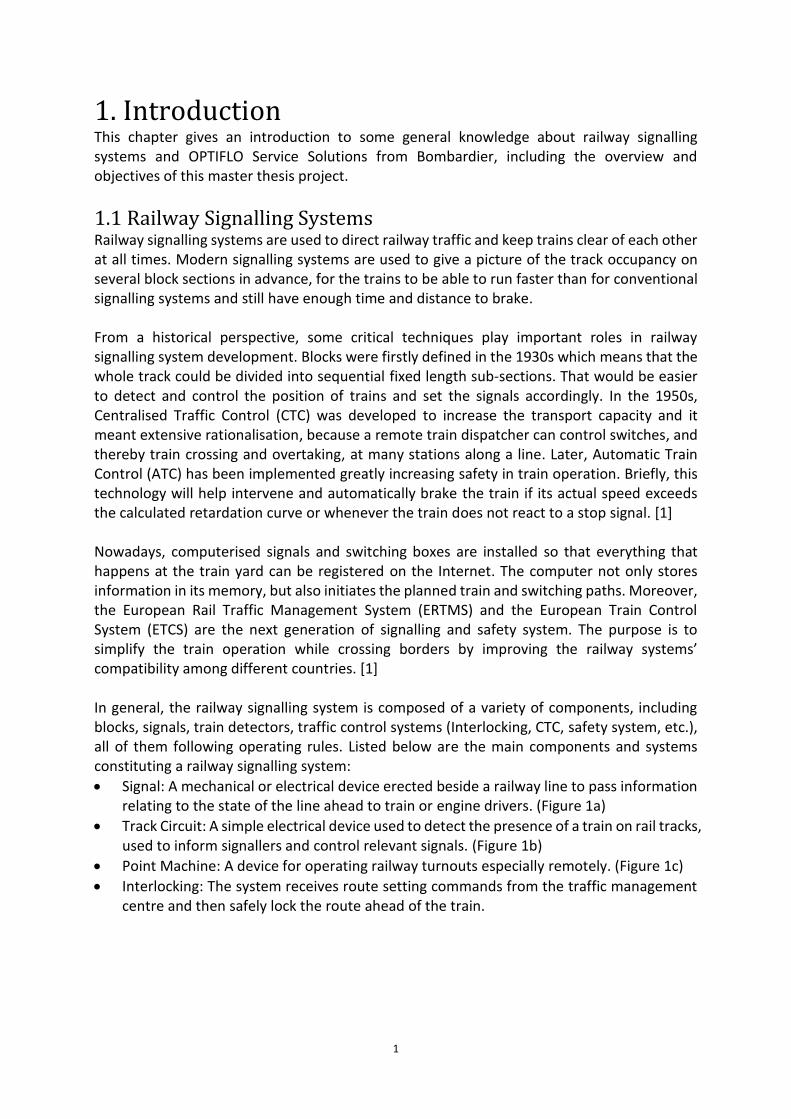
1.1 Railway Signalling Systems Railway signalling systems are used to direct railway traffic and keep trains clear of each other at all times. Modern signalling systems are used to give a picture of the track occupancy on several block sections in advance, for the trains to be able to run faster than for conventional signalling systems and still have enough time and distance to brake. From a historical perspective, some critical techniques play important roles in railway signalling system development. Blocks were firstly defined in the 1930s which means that the whole track could be divided into sequential fixed length sub-sections. That would be easier to detect and control the position of trains and set the signals accordingly. In the 1950s, Centralised Traffic Control (CTC) was developed to increase the transport capacity and it meant extensive rationalisation, because a remote train dispatcher can control switches, and thereby train crossing and overtaking, at many stations along a line. Later, Automatic Train Control (ATC) has been implemented greatly increasing safety in train operation. Briefly, this technology will help intervene and automatically brake the train if its actual speed exceeds the calculated retardation curve or whenever the train does not react to a stop signal. [1] Nowadays, computerised signals and switching boxes are installed so that everything that happens at the train yard can be registered on the Internet. The computer not only stores information in its memory, but also initiates the planned train and switching paths. Moreover, the European Rail Traffic Management System (ERTMS) and the European Train Control System (ETCS) are the next generation of signalling and safety system. The purpose is to simplify the train operation while crossing borders by improving the railway systems’ compatibility among different countries. [1] In general, the railway signalling system is composed of a variety of components, including blocks, signals, train detectors, traffic control systems (Interlocking, CTC, safety system, etc.), all of them following operating rules. Listed below are the main components and systems constituting a railway signalling system:
• Signal: A mechanical or electrical device erected beside a railway line to pass information relating to the state of the line ahead to train or engine drivers. (Figure 1a)
• Track Circuit: A simple electrical device used to detect the presence of a train on rail tracks, used to inform signallers and control relevant signals. (Figure 1b)
• Point Machine: A device for operating railway turnouts especially remotely. (Figure 1c)
• Interlocking: The system receives route setting commands from the traffic management centre and then safely lock the route ahead of the train.

2
Figure 1 Railway signalling infrastructures
1.2 Bombardier Rail Control Solutions Bombardier Rail Control Solutions aim to develop, engineer and install sophisticated railway signalling systems, and to ensure the safe and efficient operation of rail network and trains. RCS provides a series of solutions, products and platforms within Engineering & Product Development scope. From high level, solutions have been divided into three branches for different customers and applications: CITYFLO [2] for mass transit signalling system, INTERFLO [3] for main line signalling system and OPTIFLO Service Solutions [4]. This report focuses on the Infrastructure Management Service module under the framework of OPTIFLO Service Solutions.
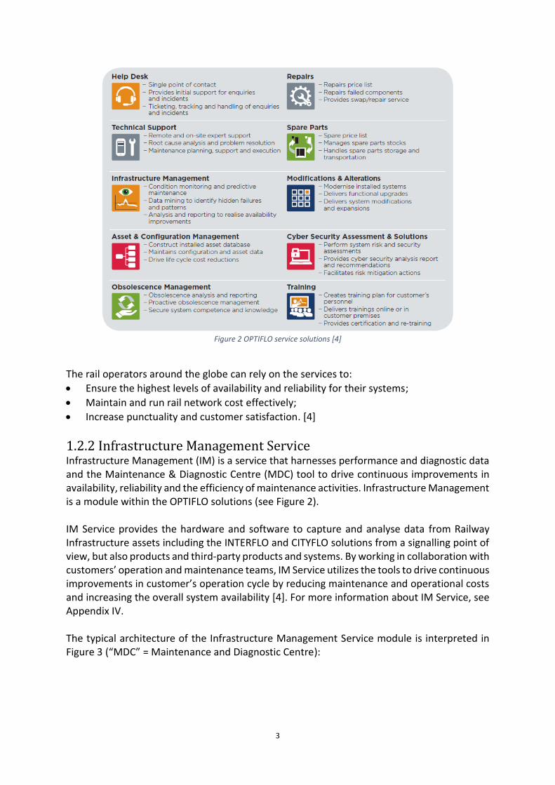
1.2.1 OPTIFLO Service Solutions OPTIFLO is the recently launched brand for Rail Control Solutions services offerings. It is a comprehensive set of service solutions tailored to address the challenges faced by railway infrastructure owners and operators [4]. OPTIFLO is designed to protect and ensure investments in rail control systems. Basically, it provides multiple services including technical support, management actions, diagnostic and monitoring functionalities, safety and security requirements, etc. for each customer application. OPTIFLO service solutions can help maximise the performance and lifespan of signalling assets with the help of professional tools, processes and high-skilled engineers [4]. And it provides tailor-made service solutions from a combination of ten service modules that can be seen in Figure 2:
3
Figure 2 OPTIFLO service solutions [4]
The rail operators around the globe can rely on the services to:
• Ensure the highest levels of availability and reliability for their systems;
• Maintain and run rail network cost effectively;
• Increase punctuality and customer satisfaction. [4]
1.2.2 Infrastructure Management Service Infrastructure Management (IM) is a service that harnesses performance and diagnostic data and the Maintenance & Diagnostic Centre (MDC) tool to drive continuous improvements in availability, reliability and the efficiency of maintenance activities. Infrastructure Management is a module within the OPTIFLO solutions (see Figure 2). IM Service provides the hardware and software to capture and analyse data from Railway Infrastructure assets including the INTERFLO and CITYFLO solutions from a signalling point of view, but also products and third-party products and systems. By working in collaboration with customers’ operation and maintenance teams, IM Service utilizes the tools to drive continuous improvements in customer’s operation cycle by reducing maintenance and operational costs and increasing the overall system availability [4]. For more information about IM Service, see Appendix IV. The typical architecture of the Infrastructure Management Service module is interpreted in Figure 3 (“MDC” = Maintenance and Diagnostic Centre):

4
Figure 3 Example of Infrastructure Management service architecture
The diagnostic and performance data from the wayside objects, for example point machines and signals, could be collected by object controllers. The collected data from non-signalling sub-systems, for example fire alarm and burglar alarm, is typically reported by the sub-systems themselves and their own products. However, where products do not report diagnostic data, then non-intrusive low cost sensors have been deployed to measure physical performance and diagnostic parameters such as electric current and temperature from signalling objects in the field (Remote Sensor Unit). All the diagnostic and performance data can be transmitted using the existing communications network, or new non-vital communication channels, for example by external sensors or radio network, which is finally to be centralized, processed and analysed in the EBI Tool MDC. The Infrastructure Management service provided by RCS includes:
• Responsive services to address the necessity of rapid reaction to failures that impede the availability for train operation
• Managing alarms & corrective support
• Investigation and data analysis services to perform in-depth analysis of batch data to enable rapid system recovery and availability enhancements
• Availability improvement service
• Predictive services to develop and refine predictive algorithms to drive continuous system performance
1.3 Thesis Overview This thesis work consists of working in close collaboration with the RCS - EAPD OPTIFLO Solution Manager, Solution Architect and the Engineers involved in development and bids. The focus is on the establishment of a requirement baseline for the Infrastructure Management module within the product.
Advanced Analytics – Data Lake –
Machine Learning
EBITool MDC
Signalling System
Network Monitoring
Station, PA, Ticketing,
liftsAsset mgt
information system
WorkstationWeb based
interface
Mobile Device
Network
Alarms, Events
Alarms, Events & Performance
Data
Alarms, Events & Performance
Data
Events
Power
Alarms, Events & Performance
Data
Performance data, Alarms, Event
Analytics data
User Interface
Event to Asset mgt

5
1.3.1 Scope The purpose is to help to finalize the requirement set for Infrastructure Management using DOORS (requirement management tool) [6], also to Identify and promote diagnostics requirement within RCS signalling products and lift them to the requirement set. The objectives are threefold:
• Help finalize and set up requirements for Infrastructure Management at system level
• Identify diagnostics requirements within RCS sub-system products and links to system level requirements
• Develop and investigate eventual tools to produce documentation from DOORS To get a better understanding of products and requirements for each RCS sub-system, it is needed to liaise with relevant stakeholders in different work areas, such as RSU Project Manager, MDC Development Team, Object Controller System (OCS) Product Manager, etc. The work is done following system engineering methodology (see Chapter 2.1) and Bombardier Transportation - RCS specific usage of it.
1.3.2 Architecture From system level to the sub-system level, this thesis work mainly covers the Infrastructure Management service module that could be linked to Maintenance and Diagnostic Centre, Object Controller System, Remote Sensor Unit, etc. The architecture of this project is given in Figure 4.
Infrastructure
Management
Maintenance &
Diagnostic Center
Object Controller
System
Remote Sensor
Unit
Computer Based
Interlocking
Computer Based
Radio
Signal - ESignal - ESwitch - ESwitch - E ......
Point MachinePoint Machine
OPTIFLO
System Level
Sub-system Level
Figure 4 Thesis project architecture
The thesis project starts with the draft of the Infrastructure Management System Requirement Specification in DOORS based on the customer demand which will impact several RCS products (part of OPTILFO solution as the sub-system) marked in green in Figure 4:
• Infrastructure Management system
6
• Maintenance and Diagnostic Centre
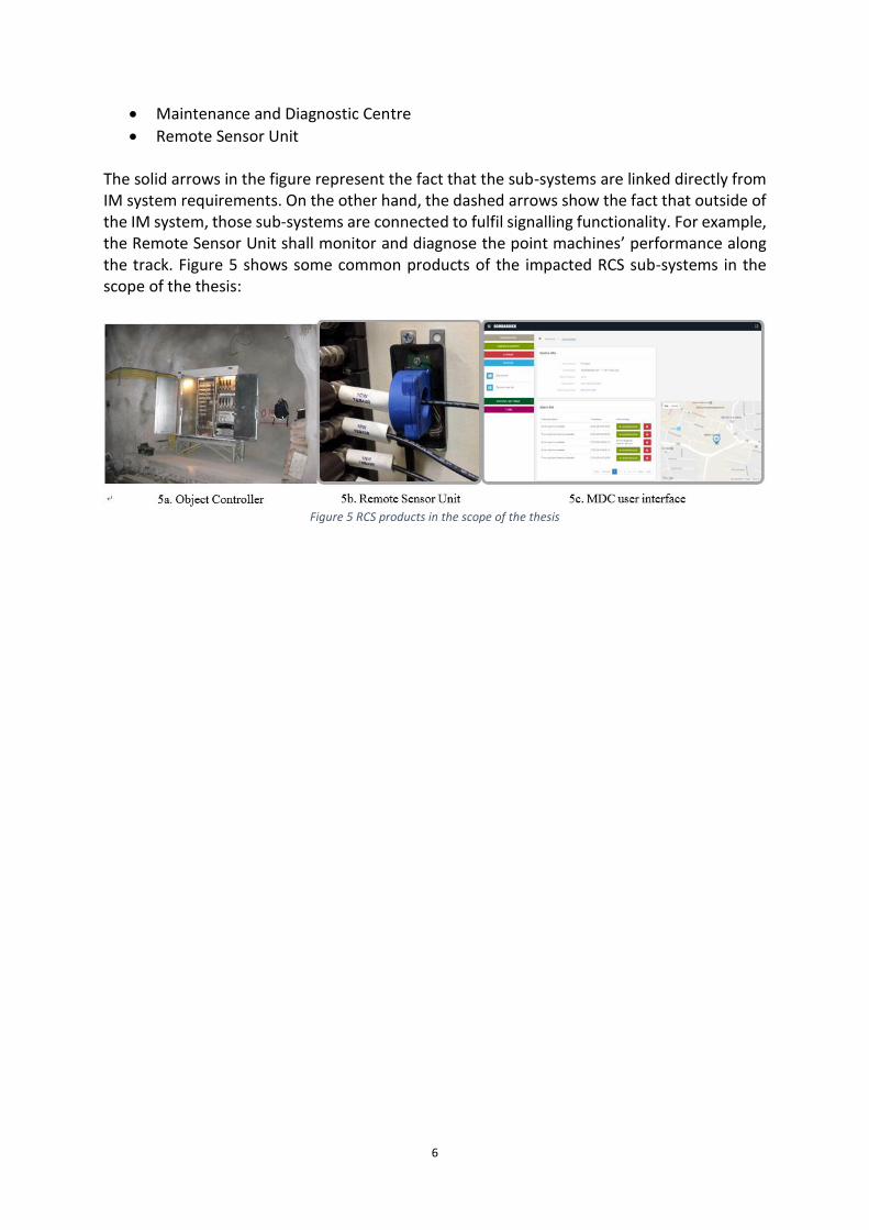
• Remote Sensor Unit The solid arrows in the figure represent the fact that the sub-systems are linked directly from IM system requirements. On the other hand, the dashed arrows show the fact that outside of the IM system, those sub-systems are connected to fulfil signalling functionality. For example, the Remote Sensor Unit shall monitor and diagnose the point machines’ performance along the track. Figure 5 shows some common products of the impacted RCS sub-systems in the scope of the thesis:
Figure 5 RCS products in the scope of the thesis

7
2. Methodology The basic method while implementing this thesis project is by following the system engineering process. System engineering is an interdisciplinary approach to create large, complex systems that meet a defined set of business and technical requirements [5]. Since the project is under the framework of OPTIFLO with a railway signalling system objective, all the rules should be in accordance with CENELEC safety standards for railway applications. Moreover, the main tool applied here is IBM Rational DOORS [6].
2.1 System Engineering System Engineering focuses on how to design and manage complex systems over their life cycles. In general, this concept contains both a practice and a process. As a practice, it is always concerned about: How a system organizes and behaves overall, how it interfaces with its users and other systems, how its sub-systems interact, and how to unite different groups to work together? As a process, system engineering clearly states a robust, structured approach to system development at high level, including concept, design, creation and operation. [5] The idea from system engineering that has been followed in this project is constructing links between requirement and design. From each unit test to the system acceptance testing to make sure the design satisfies the requirement accordingly by linking them. And how to put this idea or how to implement this concept into actions is developing and investigating system engineering process. The typical architecture of the system engineering process can be seen in Figure 6.
Figure 6 The V-model for the system engineering process [5]
While tracing the V-cycle of Figure 6 from left to right, there are four important concepts to be clarified while applying to requirement management as follows:
8
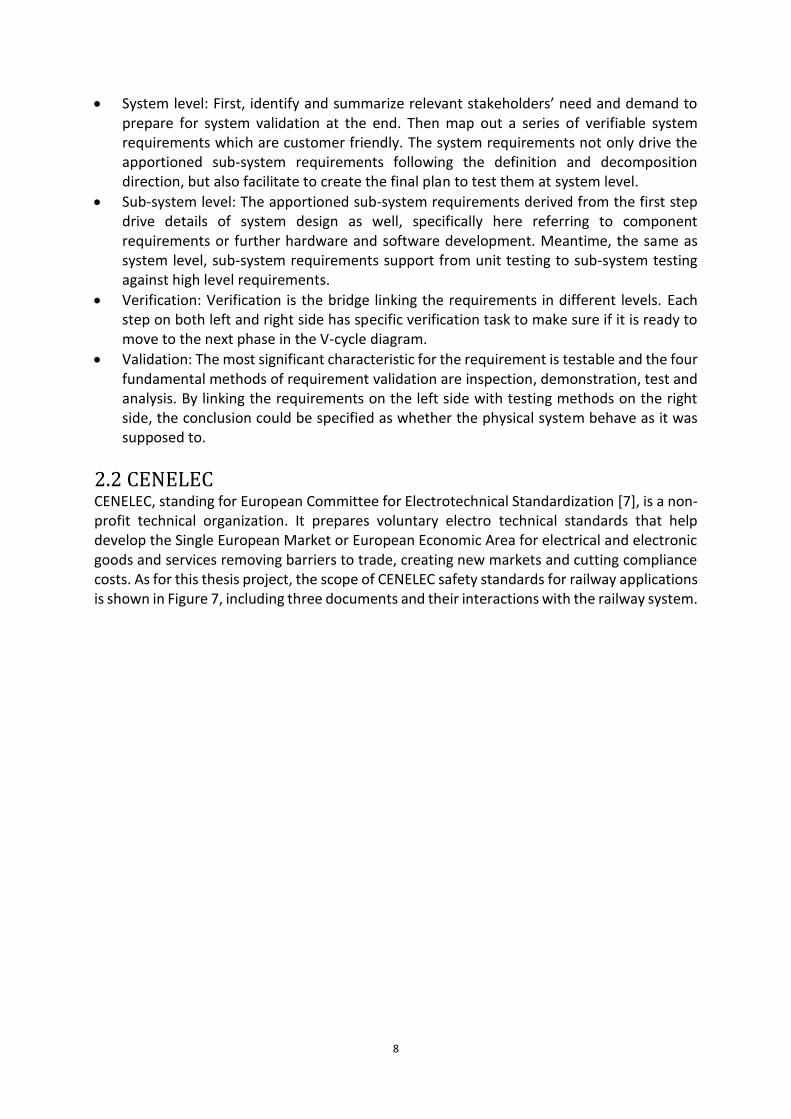
• System level: First, identify and summarize relevant stakeholders’ need and demand to prepare for system validation at the end. Then map out a series of verifiable system requirements which are customer friendly. The system requirements not only drive the apportioned sub-system requirements following the definition and decomposition direction, but also facilitate to create the final plan to test them at system level.
• Sub-system level: The apportioned sub-system requirements derived from the first step drive details of system design as well, specifically here referring to component requirements or further hardware and software development. Meantime, the same as system level, sub-system requirements support from unit testing to sub-system testing against high level requirements.
• Verification: Verification is the bridge linking the requirements in different levels. Each step on both left and right side has specific verification task to make sure if it is ready to move to the next phase in the V-cycle diagram.
• Validation: The most significant characteristic for the requirement is testable and the four fundamental methods of requirement validation are inspection, demonstration, test and analysis. By linking the requirements on the left side with testing methods on the right side, the conclusion could be specified as whether the physical system behave as it was supposed to.
2.2 CENELEC CENELEC, standing for European Committee for Electrotechnical Standardization [7], is a non-profit technical organization. It prepares voluntary electro technical standards that help develop the Single European Market or European Economic Area for electrical and electronic goods and services removing barriers to trade, creating new markets and cutting compliance costs. As for this thesis project, the scope of CENELEC safety standards for railway applications is shown in Figure 7, including three documents and their interactions with the railway system.

9
Figure 7 Scope of CENELEC safety standards for railway applications
EN 50126 [7] enables the implementation of a consistent approach to the management of Reliability, Availability, Maintainability and Safety. And safety is the state of a technical system free from unacceptable risk of harm. Moreover, Safety Integrity Level (SIL) addresses an expected level of confidence in the safety for a product with a list of tolerable hazard rate. EN 50128 [8] concentrates on the methods which need to be used to provide software which meets the demand for safety integrity which are placed upon it by these wider considerations. EN 50129 [9] defines requirements for the acceptance of safety-related electronic systems in the railway signalling field. In Bombardier, all of the solutions, products or even the components should be strictly in accordance with CENELEC standards. But OPTIFLO and Infrastructure Management do not really apply the usage of safety. On the other hand, the safety impact on the products or safety requirements should always be considered in OPTIFLO Services. And safety requirements could be generated from products or product owners. To conclude, CENELEC safety standards for railway application is the reference for the thesis project.
2.3 IBM Rational DOORS IBM Rational DOORS is a requirements management application for optimizing requirements communication, collaboration and verification throughout organization and supply chain [6]. The general user interface of one module in DOORS can be seen in Figure 8.

10
Figure 8 General user interface of IBM Rational DOORS module
IBM Rational DOORS has realized to manage the requirements in such an open and secure environment and to build links to other requirements. This management tool includes a large variety of modules for different projects that are saved in DOORS database. Within one specific module, any accessible users have the authority to edit. The main part of the module should be written in the main column and all requirements should be stated with the word “shall” or “must”. To make the module more sequential, classified and traceable, some enabling attributes and commonly used columns could be applied that are explained in Table 1.
Table 1 Examples of enabling attributes and commonly used columns in DOORS [6]
Column Introduction Example
Identity Sequence the main contents within one specific module. It
is easier for traceability while testing and linking.
IM-SRS-2
RSU-SSRS-82
Object Type An enumeration attribute defines the type of object. The
set of selectable enumeration values can differ between
modules.
Requirement
Information
Reference
Allocation
Target Scope
Indicate which sub-systems are related or the task mainly
apportioned to. Prepare for links to other requirements.
IM, MDC,
RSU, etc.
In this thesis project, the following three main functionalities of DOORS have been employed:
• Perform requirements management in a centralized location for better team collaboration. For example, work with Infrastructure Management System Requirement Specification (SRS) in a public network environment.
• Link requirements between system level IM and sub-system level to realize traceability. There are two kind of links, with in-links representing the connection from high level to surrounded sub-systems while out-links indicating the relation from sub-systems to system level [6].
• Publish standard documentation for customers accordingly. For example, release System Requirement Specification for Remote Sensor Unit project.

11
3. Results This chapter elaborates the main body and work done of the present master thesis, following the methodology articulated in the previous chapter. It has been divided into three sections:
• System level Infrastructure Management requirements
• Sub-system level MDC requirements
• Remote Sensor Unit project The general procedure to finish each sub-task is by following the system engineering process, referring to CENELEC standards for railway applications where applicable and managing requirements in DOORS. Thereafter, the proper links are finished in DOORS and requirements have been updated with the documentations to be released.
3.1 Infrastructure Management System Requirement Specification Infrastructure Management is an important service module of OPTIFLO service solution which performs responsive, analysis and predictive functionalities (For details, see Appendix IV). The purpose of this section is to release IM SRS which specifies the system level requirements for Infrastructure Management.
3.1.1 System Requirements The old version document of IM SRS in DOORS was generated based on the customer demand. It has been divided into more than a dozen of chapters, including High Level Requirement, Required Diagnostic Information, Information Display and User Functions, etc. By following the system engineering process shown in Figure 9, all the Infrastructure Management requirements should not only be written verifiable that correspond to system acceptance testing, but also be prepared to drive the apportioned sub-system requirements. In this thesis project, the later aspect has been focused to realize the traceability between system level and sub-system level, because the test specification of IM is not available in the current stage.
Figure 9 V cycle representation for Infrastructure Management
One important concept that should be interpreted beforehand is the diagnostic system and its relation with the monitored system. The typical architecture of diagnostic system is shown in Figure 10 (“MDC” = Maintenance and Diagnostic Centre, “CBI” = Computer Based Interlocking, “CBR” = Computer Based Radio, “OCS” = Object Controller System, “RSU” =

12
Remote Sensor Unit, “AC” = Air Conditioning, “TMS” = Traffic Management System, “PM” = Point Machine, “BM” = Barrier Machine).
Figure 10 The typical architecture of diagnostic system
In general, the diagnostic system consists of several sub-systems including part of signalling system with MDC as the core. It has become the most important composition in railway infrastructures to improve availability and maintainability, furthermore increasing the profits. In some cases, the diagnostic system is the monitored system. For example, as shown in Figure 11, CBI, CBR, OCS are part of the diagnostic system because they provide diagnostics. On the other hand, they are also part of the signalling system as the intersection between the Diagnostic System and the Monitored System.
Diagnostic System Monitored System
CBR
CBI
OCS
PM
BM
MDC
RSU
Figure 11 Intersection between the diagnostic system and the monitored system

13
After receiving the comments and suggestions from the Solution Manager and the MDC Team, three fundamental modifications have been employed: First, it is better to add the document overview including the Definitions and Abbreviations Chapter at the beginning. Since this document is released for general readers, not everybody would be familiar with Infrastructure Management or even some abbreviations are unique in Bombardier. When someone is reading the document, the basic structure of Infrastructure Management should be created in their minds at least. Moreover, some supporting drawings could be added as well. For example, when introducing the configuration control, “The diagnostic system shall provide configuration control functions”, one architecture of configuration control process could be added to explain how the system works to realize this functionality. Second, prevent duplicated requirements. This is a tricky task with a series of assessments to do. Because some requirements just repeat the previous one in another way that could be identified easily. But some requirements seem duplicated, while applicable for different purposes or different sub-systems. See one example in Table 2:
Table 2 Comparison between two similar requirements
Identity Requirement Chapter
IM-SRS-
9
The diagnostic system shall help the maintenance
technician to identify needed maintenance
activities based on analysis and trends of values
monitored by the diagnostic system.
4 High Level Requirement
IM-SRS-
188
The diagnostic system shall provide its user with
a troubleshooting system for the Monitored
System, including a comprehensive set of help
tips.
10.2 Diagnostic User
Function
It is clear that both the requirements concern analysis service of the diagnostic system. On the one hand, No.9 explains the general functionality of the diagnostic system for maintenance purpose. On the other hand, No.188 specifies the occasion in case the troubleshooting system is detected. They are applicable for different scenarios, and the former one is more generic compared to the user function’s requirement. That is why No.9 is allocated in High Level Requirement Chapter of IM SRS. Last but not the least, remove the requirements that are too detailed. This document specifies the system requirements at a high level. Therefore, all the requirements should be written with high compatibility and wide range of usage. Compare one example from Chapter 10 Information Display and User Functions of IM SRS in Table 3.
Table 3 One modification to be more general
Identity Requirement
IM-SRS-
204
The diagnostic system shall support a terminal emulation solution enabling
remote access to the diagnostic system.
IM-SRS-
216
Remote access (for example from another diagnostic workstation or via the
Internet) of the diagnostic system shall be possible.

14
This requirement is assigned in Chapter 10.4 Terminal Emulation of IM SRS. When talking about the emulation solution, the user interface will be considered as well, for example, whether the web interface is sufficient or not. Therefore, this requirement is more like to interpret how to realize remote access which should not be detailed at IM level. Finally, this requirement is rephrased and combined with another one stated as No.216 in Table 3. A different problem is found in Chapter 16 Juridical Recorder Function of IM SRS. JRU is a module within MDC that records the collected data from related sub-systems. Most requirements in chapter JRU are not from system level and even another DOORS module has already specified the JRU requirements from a sub-system point of view. So almost all requirements in this chapter have been removed with only two high level requirements left. Moreover, some minor corrections for each chapter have been completed.
3.1.2 Verification Verification is a concept used in system engineering and project management. It has different meanings for different applications. Here, based on the system engineering process shown in Figure 9, each step has a specific verification task, if it is ready to move to the next phase in the V cycle. Specifically, verification basically builds the bridge between system requirements and apportionment, whether one requirement in system level can also be specified in other sub-system modules in DOORS, such as MDC SSRS, RSU SSRS, etc. or could be linked to other sub-system requirements accordingly. Thereafter, Allocation Target Scope column has been added in IM SRS to prepare for links and traceability in DOORS. See Figure 12, the fourth column:
Figure 12 Snap shot of IM SRS module in DOORS
The clear criterion should be created before deciding the tags of Allocation Target Scope for each requirement. And the tags here indicate that the requirement could be apportioned to the corresponding sub-system for future works. Some examples are explained as follows: Pick “IM-SRS-2” in Figure 12, “The diagnostic system shall not affect the function of the Monitored System (including the signalling system) in any way”. This requirement can only be achieved by collaborating all systems within the diagnostic system, from the whole system

15
level. It concerns not only the functionality of each system themselves, but also the communication between them. So, put the “IM” tag here. And see “IM-SRS-4” in Figure 12, “The diagnostic system shall continuously monitor the condition and behaviour of the Monitored system”. MDC as the core of the diagnostic system, connecting adjacent sub-systems, report, analyse and display the conditions and performance of each monitored system. The other way, MDC will completely do this functionality. So, tag “MDC” for this requirement. Finally, choose “IM-SRS-13” in Figure 12, “The diagnostic system shall continuously monitor and detect security breaches, and raise alarms accordingly”. It seems that this requirement should also be allocated to MDC, because MDC collects such information from each sub-system. But security breaches and alarms will be produced by each sub-system in case some problems happen. First, each system will self-diagnose internal problems and then transmit diagnostic information or alarms to MDC through corresponding interfaces. MDC will never detect security breaches for each sub-system individually. So, it is better to tag “all sub-systems” for this requirement.
3.1.3 Released Document After solving the foremost problems stated in the previous section and tagging each requirement for future links, this document has better structure than before. Moreover, additional minor modifications, like some requirements should be stated more precisely or some clarifications could be employed after the requirements which are hard to understand. Thereafter, review the language problem, update the table of contents and publish the standard documentation from DOORS. The latest version for IM SRS is 1.0, that has been released. For the updated table of contents for IM SRS Version 1.0, see Appendix I.
3.2 Maintenance and Diagnostic Centre Requirements Maintenance and Diagnostic Centre (MDC) is a modern maintenance and diagnostic system for mainline and mass transit railways. MDC collects, analyses and presents performance and diagnostic event and alarm data from railway infrastructure assets. For more information about its user interface, key features or even use case examples, refer to Appendix V. The present work is originating from the old version document MDC SSRS in DOORS. All the requirements for MDC are created based on its operating principles and other feedbacks from general users. This module consists of both functional and non-functional requirements. Functional requirements are formulated within data collection, data process and output, while non-functional requirements contain performance, interface, configuration, security, etc. Since the document of MDC SSRS still needs to be improved, the work is in progress. For the table of contents for the latest MDC SSRS version, see Appendix II. The progress and improvement of MDC requirements made can be summarised as below:
• Provide some general feedbacks from system level point of view;
• Propose solutions to deal with Generic Application (GA) and Generic Product (GP) requirements;
• Identify the MDC requirements that could be linked to IM requirements.

16
First, the same suggestions as updating IM requirements, the Definitions and Abbreviations Chapter should be added at the beginning. Moreover, some necessary supporting drawings and clarifications could also be supplied following each requirement in addition to other minor corrections. See two examples in Table 4.
Table 4 Examples of MDC requirements needing more explanations
Identity Requirement
MDC-2453 MDC shall be horizontally scalable.
MDC-2517 If MDC loses connection with the external user management system, then
MDC shall keep the authentication for a logged in user.
As for “MDC-2453”, the topology chapter is required to show its vertical relation and to interpret how many objects, for example local MDC, need to satisfy the requirement. This requirement negotiates the capacity of each local MDC, therefore a clear definition about horizontally scalable should be given before. And for “MDC-2517”, this requirement concerns communications between MDC and other external systems, it is better to show the software architecture beforehand to define which system could be regarded as one external user management system with MDC. The most challenging problem while dealing with MDC requirements is that this module has mixed both GP and GA requirements. Take EBI Com 2000 Radio Block Centre as an example to distinguish these two concepts: EBI Com 2000 is a typical Bombardier product used to supervise communications between Interlocking and trains. Generic Product CBR2 is common for all RBC installations, while Generic Application CBR2_XX is common for all RBC installation only in one country. The snap shot of MDC SSRS from DOORS including the GP_GA column can be seen in Figure 13.
Figure 13 Snap shot of MDC SSRS module in DOORS
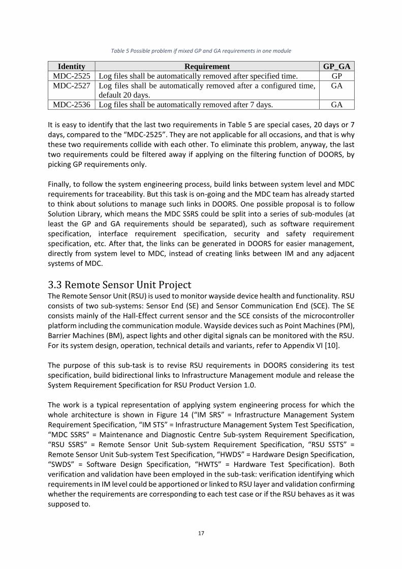
Furthermore, Table 5 shows one possible problem if GP and GA requirements are not separated.
17
Table 5 Possible problem if mixed GP and GA requirements in one module
Identity Requirement GP_GA
MDC-2525 Log files shall be automatically removed after specified time. GP
MDC-2527 Log files shall be automatically removed after a configured time,
default 20 days.
GA
MDC-2536 Log files shall be automatically removed after 7 days. GA
It is easy to identify that the last two requirements in Table 5 are special cases, 20 days or 7 days, compared to the “MDC-2525”. They are not applicable for all occasions, and that is why these two requirements collide with each other. To eliminate this problem, anyway, the last two requirements could be filtered away if applying on the filtering function of DOORS, by picking GP requirements only. Finally, to follow the system engineering process, build links between system level and MDC requirements for traceability. But this task is on-going and the MDC team has already started to think about solutions to manage such links in DOORS. One possible proposal is to follow Solution Library, which means the MDC SSRS could be split into a series of sub-modules (at least the GP and GA requirements should be separated), such as software requirement specification, interface requirement specification, security and safety requirement specification, etc. After that, the links can be generated in DOORS for easier management, directly from system level to MDC, instead of creating links between IM and any adjacent systems of MDC.
3.3 Remote Sensor Unit Project The Remote Sensor Unit (RSU) is used to monitor wayside device health and functionality. RSU consists of two sub-systems: Sensor End (SE) and Sensor Communication End (SCE). The SE consists mainly of the Hall-Effect current sensor and the SCE consists of the microcontroller platform including the communication module. Wayside devices such as Point Machines (PM), Barrier Machines (BM), aspect lights and other digital signals can be monitored with the RSU. For its system design, operation, technical details and variants, refer to Appendix VI [10]. The purpose of this sub-task is to revise RSU requirements in DOORS considering its test specification, build bidirectional links to Infrastructure Management module and release the System Requirement Specification for RSU Product Version 1.0. The work is a typical representation of applying system engineering process for which the whole architecture is shown in Figure 14 (“IM SRS” = Infrastructure Management System Requirement Specification, “IM STS” = Infrastructure Management System Test Specification, “MDC SSRS” = Maintenance and Diagnostic Centre Sub-system Requirement Specification, “RSU SSRS” = Remote Sensor Unit Sub-system Requirement Specification, “RSU SSTS” = Remote Sensor Unit Sub-system Test Specification, “HWDS” = Hardware Design Specification, “SWDS” = Software Design Specification, “HWTS” = Hardware Test Specification). Both verification and validation have been employed in the sub-task: verification identifying which requirements in IM level could be apportioned or linked to RSU layer and validation confirming whether the requirements are corresponding to each test case or if the RSU behaves as it was supposed to.

18
IM SRS
MDC SSRS RSU SSRS
IM STS
SWDS
RSU SSTS
Code
Executable
HWDS
Hardware
Designed
HWTS
Verification Verification
Validation
Validation
Figure 14 System engineering process application for Remote Sensor Unit project
In the whole V-cycle diagram, one system module could be connected to a series of sub-modules or have more than one branch. For example, IM could be linked to both MDC and RSU or continuously the RSU could be divided into hardware design and software design modules. Meanwhile, each step on the left side should link to its test specification. This sub-task focuses on the verification from IM SRS to RSU SSRS and validation from RSU SSRS to RSU SSTS indicated in Figure 14.
3.3.1 Verification The sub-task starts with the old version requirement specification for Remote Sensor Unit project based on the RSU’s attributes, functionalities, CENELEC Environmental Conditions [11], CENELEC Electromagnetic Compatibility [12], etc. First, pick up all the requirements in IM SRS module tagged by “sensors” and “all sub-systems” from DOORS. Then review all the RSU requirements to identify which of them could be linked to these filtered requirements in IM SRS. Moreover, if some requirements are missed in RSU SSRS following high level requirement, add them accordingly, because the linked requirements in both two modules should be consistent with each other. Part of the solution can be retrieved in Table 6.
19
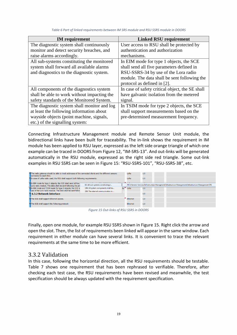
Table 6 Part of linked requirements between IM SRS module and RSU SSRS module in DOORS
IM requirement Linked RSU requirement
The diagnostic system shall continuously
monitor and detect security breaches, and
raise alarms accordingly.
User access to RSU shall be protected by
authentication and authorization
mechanisms.
All sub-systems constituting the monitored
system shall forward all available alarms
and diagnostics to the diagnostic system.
In EIM mode for type 1 objects, the SCE
shall send all five parameters defined in
RSU-SSRS-34 by use of the Lora radio
module. The data shall be sent following the
protocol as defined in [2].
All components of the diagnostics system
shall be able to work without impacting the
safety standards of the Monitored System.
In case of safety critical object, the SE shall
have galvanic isolation from the metered
signal.
The diagnostic system shall monitor and log
at least the following information about
wayside objects (point machine, signals,
etc.) of the signalling system:
In TSIM mode for type 2 objects, the SCE
shall support measurements based on the
pre-determined measurement frequency.
Connecting Infrastructure Management module and Remote Sensor Unit module, the bidirectional links have been built for traceability. The in-link shows the requirement in IM module has been applied to RSU layer, expressed as the left side orange triangle of which one example can be traced in DOORS from Figure 12, “IM-SRS-13”. And out-links will be generated automatically in the RSU module, expressed as the right side red triangle. Some out-link examples in RSU SSRS can be seen in Figure 15: “RSU-SSRS-101”, “RSU-SSRS-38”, etc.
Figure 15 Out-links of RSU SSRS in DOORS
Finally, open one module, for example RSU SSRS shown in Figure 15. Right click the arrow and open the slot. Then, the list of requirements been linked will appear in the same window. Each requirement in either module can have several links. It is convenient to trace the relevant requirements at the same time to be more efficient.
3.3.2 Validation In this case, following the horizontal direction, all the RSU requirements should be testable. Table 7 shows one requirement that has been rephrased to verifiable. Therefore, after checking each test case, the RSU requirements have been revised and meanwhile, the test specification should be always updated with the requirement specification.

20
Table 7 Verifiable requirements
Requirement “RSU-SSRS-8”
Original The SCE shall support an external voltage supply of 5VDC.
Updated The SCE shall support an external voltage supply of 5VDC ± 15%. The SCE shall
use no more than 2.5A.
The original requirement in Table 7 just states the external voltage supply should be exactly 5VDC. But in this case, the maximum current consumption and voltage tolerance should be taken into consideration from a scientific point of view. For the updated requirement, while testing, the RSU should be fed by external voltage of all three scenarios: 4.25VDC, 5VDC and 5.75VDC with the limit of current magnitude and check its behaviour. Below are the tests required to validate the requirements. The tests are divided into four categories reflecting the type of test to be performed:
• Inspection: Test routine consists of optical recognition of the requirement.
• Measurements: Test routine consists of simpler measurements with multi-meter or oscilloscope.
• Mechanical: Test routine consists of mechanical check. Does the connector fit?
• Functional: Test routine consists of one or several complex steps. In this report, some representative test cases are selected in Table 9 including the test routine and expected result following the matching RSU requirements listed in Table 8.
Table 8 Part of RSU requirements
Identity Requirement
RSU-SSRS-118 The SCE shall have 7 SE inputs and support all the inputs to be used in
any operational mode at the same time.
RSU-SSRS-21 Electrical connectors for the SCE shall be available from more than one
manufacturer.
RSU-SSRS-50 The RSU shall be mounted in either racking and/or closed boxes as
appropriate and shall be designed for easy removal for maintenance
purposes.
RSU-SSRS-34 In EIM mode for type 1 objects, the SCE shall calculate the RMS, mean,
minimum, maximum values and the duration of the saved waveform.

21
Table 9 Test cases corresponding to the requirements in Table 7
RSU-SSRS- Type of
test
Test routine Expected result
118 Inspection Check the number of
connectors on the SCE.
There shall be at least 7
connectors.
21 Analysis Check second source of the
electrical connectors.
There should be more than
one manufacturer.
50 Mechanical Access the closed boxes with
debug tools and maintenance
equipment.
The RSU shall be designed
for easy removal in closed
boxes.
34 EIM1 Generate a default EIM Type 1
object and check the result.
Check for alarms.
The EIM Type 1 object
shall be identified with
default values and with
acceptable tolerance.
Alarms have been received.
3.3.3 Released Documentation for RSU Version 1.0 Since the current work on the RSU project roadmap is to release standard documentation for RSU Product Version 1.0, some of the requirements are not applicable in the present stage but could be realized in the future, for example RSU Product Version 1.1 or 2.0. See some examples in Table 10:
Table 10 Requirements applicable for different RSU product versions
Requirement RSU product version
The SCE shall support Ethernet access. 1.0
The RSU shall be able to forward alarms to the diagnostic system
by radio or wired network.
1.1
The SCE shall support USB access (for configuration and
installation purpose).
2.0
To deal with this problem, the columns Variant and RSU Version have been implemented in this module which can be seen in Figure 16. Tags in the column Variant indicate which aspect each requirement describes, such as Split, Battery, Ethernet, LoRa, etc. Different combinations of variants could represent the rationale of dissimilar RSU products, while the RSU Version column is used for export purpose.

22
Figure 16 Snap shot of RSU SSRS in DOORS
After applying the filter function in DOORS by only picking the requirements tagged by RSU Product Version 1.0, the standard documentation required in this project has been released. This document specifies the requirements for the Remote Sensor Unit (RSU product Version 1.0). The requirements are divided into Interface Requirements, Product Requirements, Functional Requirements, Environmental Requirements, Installation & Commissioning Requirements and Security Requirements. For the table of contents of the released System Requirement Specification Version 1.2 for Remote Sensor Unit, see Appendix III.

23
4. Conclusions and Discussion The previous requirements in the Infrastructure Management system are originating from customer demands. After solving critical problems while updating this document, for instance, identifying in which areas these requirements are employed, accurately allocate each requirement to its sub-modules within IM scope. Links to the Remote Sensor Unit module in DOORS have been built afterwards. Finally, the System Requirement Specification Version 1.0 for Infrastructure Management has been released. The original requirements for MDC mainly come from its operating principle or general users’ feedbacks. Some solutions about how to separate GA and GP requirements are proposed and other trivial aspects have been updated while taking system level requirements into consideration. The System Requirement Specification for the Maintenance and Diagnostic Centre is still under revision. The Remote Sensor Unit project is a typical representative of applying the system engineering process (see Figure 13). To realize validation, all the requirements should correlate with their test cases. To do verification, diagnose the RSU requirements that could be linked back to system requirements at high level. Moreover, distinguish each requirement for different RSU variants and different RSU product versions (1.0 is the current RSU product version). The System Requirement Specification Version 1.2 for Remote Sensor Unit Product Version 1.0 has been released at the end. All the requirements for both system and its sub-system modules could derive from customer demands, operating principles, common users’ feedbacks or CENELEC standards (MDC is non-safety related). Following the system engineering process (see Figure 6), from high level, start with system specification. While updating requirements at each step, by considering both horizontal and slant directions, the requirements should not only correspond to their test specifications, but also be linked to other requirements at different levels. The general approach is to identify the system requirements that could be apportioned or implemented to its sub-systems, and vice versa. The final goal is managing the requirements for each module in IBM Rational DOORS. While finished, prepare the links for traceability. In this case, the links could be built between the requirements or connected between the requirement and its test case. Finally, filter the requirements applicable in the current stage (user friendly) when necessary and export standard documentations from DOORS accordingly. The real challenge while dealing with engineering problems is one of organisation: how can we effectively and efficiently integrate a complex combination of technologies to create a thorough system that fulfils its promises and lives up to its potential? The solution lies with system engineering. System engineering is a fundamental subject for all industries, for example in the fields of railways, aerospace and telecom. And it is an effective approach and process while managing a complex system containing a variety of surrounding sub-systems to approve a deterministic outcome. The internal arrangement within one individual system should be well organised first and its correlations to the external systems should also be considered to deal with their impacts and to build bridges between them. In that way, all related systems or components

24
within one project or product will work efficiently as a whole, which is also the basic requirement for modern operating modes and product development. Another conclusion is the importance of the Infrastructure Management Service affecting the railway signalling system. IM is the recently launched service that has extensive applications in other areas as well. This report focuses on the advantage of IM mainly for railway signalling, which will help to reduce the maintenance and operational costs and improve the system availability to ensure a steady flow of profits for the railway industry.

25
5. Recommendations The System Test Specification for Infrastructure Management system could be provided to complete the whole system engineering V cycle shown in Figure 9. Moreover, it is important to judge in which stage of the solution version, the IM requirements should be released. This is because some of them cannot be deployed for the system currently. Solution Library is a new method to deal with MDC requirements by separating the system MDC module into a series of sub-modules for good organisation. This solution could be successfully applied here which would be easier to manage the links between IM system and MDC level. For the future RSU product versions, some of the previous requirements should be updated at the same time. And a number of new requirements should be implemented, for example, the self-diagnostic function, next generation requirements or some new technologies about data transmission, etc. Another perspective is Cyber Security Requirements. Actually, this is a compulsory assessment for every system, but not directly discussed in this report. The purpose is to identify which requirements in a cyber security scope could be implemented into each system and define the level accordingly. This should be finished by cooperating with INTERFLO and CITYFLO Group to arrive at a feasible point.
26
References [1] B-L. Nelldal, A. Lindahl, Railway Traffic Planning - Chapter 5, KTH Railway Group, Division
of Traffic and Logistics, Royal Institute of Technology (KTH), Stockholm, 2011-09-28 [2] CITYFLO - Signalling for Mass Transit, Bombardier Inc. or its subsidiaries,
UK/11396/RCS/03-2014/en [3] High Speed Rail Control - The Fast Track to Sustainable Mobility, Bombardier Inc. or its
subsidiaries, UK/11393/RCS/06-2014/en [4] OPTIFLO - Rail Control Service Solutions, Bombardier Inc. or its subsidiaries,
UK/PV/RCS/09-2016/en [5] C. Shamieh, System Engineering for Dummies, Wiley Publishing, Inc., Indianapolis, Indiana,
2011 [6] O. Trangjaijing, R. Lauer, B. Lundberg, DOORS Short Instructions, 100137473, Version 1.0
(2013) [7] Railway application - The specification and demonstration of Reliability, Availability,
Maintainability and Safety (RAMS), CENELEC, EN 50126: 1999 [8] Railway application - Communications, signalling and processing systems - Software for
railway control and protection systems, CENELEC, EN 50128: 2001 [9] Railway application - Communications, signalling and processing systems - Safety related
electronic systems for signalling, CENELEC, EN 50129: 2016 [10] E. Milh, D. Forsberg, Product Description - Remote Sensor Unit, 1DOC-1019375, Version
1.1 (2017) [11] Railway applications - Environmental conditions for equipment, Part 3: Equipment for
signalling and telecommunications, CENELEC, EN 50125-3: 2003 [12] Railway applications - Electromagnetic compatibility, Part 4: Emission and immunity of
the signalling and telecommunications apparatus, CENELEC, EN 50121-4: 2015

27
Appendices Appendix I Table of Contents for IM SRS Version 1.0

28
Appendix II Updated Table of Contents for MDC SSRS

29
Appendix III Table of Contents for RSU SSRS Version 1.2

30
Appendix IV Infrastructure Management Service Module

31

32

33

34
Appendix V EBI Tool Maintenance and Diagnostic Centre

35

36

37

38
Appendix VI Product Description - Remote Sensor Unit Extract

39

40

41

42

43