Rail Accident Report - gov.uk · Report 02/2014 January 2014 Rail Accident Report Derailment at...
41
Report 02/2014 January 2014 Rail Accident Report Derailment at Castle Donington, Leicestershire 21 January 2013
Transcript of Rail Accident Report - gov.uk · Report 02/2014 January 2014 Rail Accident Report Derailment at...
Report 02/2014January 2014
Rail Accident Report
Derailment at Castle Donington, Leicestershire 21 January 2013
This investigation was carried out in accordance with:
l the Railway Safety Directive 2004/49/EC;l the Railways and Transport Safety Act 2003; and l the Railways (Accident Investigation and Reporting) Regulations 2005.
© Crown copyright 2014 You may re-use this document/publication (not including departmental or agency logos) free of charge in any format or medium. You must re-use it accurately and not in a misleading context. The material must be acknowledged as Crown copyright and you must give the title of the source publication. Where we have identified any third party copyright material you will need to obtain permission from the copyright holders concerned. This document/publication is also available at www.raib.gov.uk.
Any enquiries about this publication should be sent to:
RAIB Email: [email protected] Wharf Telephone: 01332 253300Stores Road Fax: 01332 253301 Derby UK Website: www.raib.gov.ukDE21 4BA
This report is published by the Rail Accident Investigation Branch, Department for Transport.

Report 02/2014Castle Donington
3 January 2014
Derailment at Castle Donington, Leicestershire, 21 January 2013
Contents
Summary 5Introduction 6
Preface 6Key definitions 6
The accident 7Summary of the accident 7Context 8Events preceding the accident 12Events during the accident 13Events following the accident 14
The investigation 15Sources of evidence 15
Key facts and analysis 16Background information 16Identification of the immediate cause 19Identification of causal factors 20Identification of underlying factors 27Observations 29Occurrences of a similar character 29
Summary of conclusions 30Immediate cause 30Causal factors 30Underlying factors 31Additional observations 31
Previous RAIB recommendations relevant to this investigation 32Actions reported as already taken or in progress relevant to this report 33Learning points 34Recommendations 35Appendices 36
Appendix A - Glossary of terms 36

Report 02/2014Castle Donington
4 January 2014
This page is intentionally left blank

Report 02/2014Castle Donington
5 January 2014
Summary
At about 19:55 hrs on 21 January 2013, a freight train consisting of 26 empty wagons, hauled by a diesel locomotive, derailed at Castle Donington, Leicestershire. The eighteenth wagon derailed first, followed by the nineteenth and twentieth wagons. Subsequently, the train divided between the nineteenth and twentieth wagons, causing the brake to apply. There was extensive track damage, but no-one was hurt.The immediate cause was that cyclic top before the point of derailment excited the suspension of the eighteenth wagon causing the left-hand leading wheel to become unloaded and to derail to the left. There had been a recurrence of cyclic top faults in the vicinity of where the derailment occurred, and the routine inspection and maintenance had not kept the track in an acceptable condition. In particular, planned stoneblowing on 20 November 2012, which should have included the track through the point of derailment, stopped before reaching it due to shortage of time. An underlying factor was that the ballast supporting the track was fouled, causing the track to be inadequately supported and leading to the recurrent cyclic top. The need to renew the ballast had been identified, but the work was not programmed to be carried out until 2016/17. This was in line with Network Rail’s policy for renewals on the route.The RAIB has made two recommendations, one directed to Network Rail and one to RSSB. The recommendation to Network Rail covers reviewing, and if necessary, improving the planning of stoneblowing so that there is sufficient time to complete the work. The recommendation to RSSB (in conjunction with the rail industry) is to review the current Rule Book requirements relating to the action required following an abnormal brake application, and to make any changes found necessary to reduce the risk of trains colliding with a derailed rail vehicle.The RAIB has also identified three learning points about: l checking track, following the passage of trains, after lifting and packing work; l using appropriately qualified staff to raise speed restrictions following work to
remedy poor track condition; and l staff communicating safety information so that it is clearly and accurately
understood.
Sum
mar
y

Report 02/2014Castle Donington
6 January 2014
Introduction
Preface1 The purpose of a Rail Accident Investigation Branch (RAIB) investigation is to
improve railway safety by preventing future railway accidents or by mitigating their consequences. It is not the purpose of such an investigation to establish blame or liability.
2 Accordingly, it is inappropriate that RAIB reports should be used to assign fault or blame, or determine liability, since neither the investigation nor the reporting process has been undertaken for that purpose.
3 The RAIB’s investigation (including its scope, methods, conclusions and recommendations) is independent of all other investigations, including those by the safety authority or railway industry.
Key definitions4 All dimensions and speeds in this report are given in metric units, except speed
and locations which are given in imperial units, in accordance with normal railway practice. Where appropriate the equivalent metric value is also given.
5 All mileages in this report are measured from a zero datum at London St Pancras station for the line from Sheet Stores Junction to Stenson Junction on which the derailment occurred.
6 The report contains technical terms (shown in italics the first time they appear in the report). These are explained in appendix A.
Introduction

Report 02/2014Castle Donington
7 January 2014
Figure 1: Extract from Ordnance Survey map showing location of derailment
© Crown Copyright. All rights reserved. Department for Transport 100039241. RAIB 2013
Location of derailment
The accident
Summary of the accident 7 At about 19:55 hrs on 21 January 2013, the eighteenth wagon of a freight train,
travelling from Crewe Basford Hall to Toton, derailed at Castle Donington, Leicestershire (figure 1). The train, which was travelling at 47 mph (76 km/h), continued and the following two wagons in the train were pulled into derailment as the train passed over a trailing crossover. Subsequently, the train divided between the nineteenth and twentieth wagons causing the train’s automatic brake to apply. The train finally stopped near the village of Hemington, having run for about a mile (1.6 km) from the initial point of derailment, and with the twentieth wagon obstructing the adjacent line.
8 During the derailment, an empty passenger train was approaching on the adjacent line, but was stopped before reaching the derailed train when the signaller, aware that an incident might have occurred, replaced signals to red.
9 No-one was injured in the derailment. The three derailed wagons caused damage to the track and signalling equipment, particularly at the crossover. The three derailed wagons were also damaged to a limited extent.
10 The line was closed to traffic while the damage was repaired, and it reopened at 13:58 hrs on 26 January 2013.
The
acci
dent

Report 02/2014Castle Donington
8 January 2014
Figure 2: Location of the Stenson Junction to Sheet Stores Junction line
Route taken by train 6Z68
Not to scale
N
Ambergate
Belper
Duffield
DerbyPeartree
Stoke-on-Trent
Castle Donington
Sheet Stores Jn
Birmingham New Street
Burton-on-Trent
Stenson Jn.
Long Eaton
Trent
Toton sidings
Langley Mill
Chesterfield
Chesterfield
Bulwell
Nottingham
Beeston
Attenborough
East Midlands Parkway
Leicester and London St. Pancras
Direction of travel of train 6Z68
ContextLocation11 Castle Donington is on the double-track railway between Stenson Junction
and Sheet Stores Junction (figure 2) and is of track category 4. The two lines are known as the up and down Chellaston lines. The line is mainly used by freight trains, but is also used by empty passenger trains, charter trains and as a diversionary route for passenger trains. The initial point of derailment was at 123 miles 1502 yards.
12 The train, reporting number 6Z68, was travelling on the up Chellaston line (figure 3), which has a permissible speed of 50 mph (80 km/h), and consists of continuous welded rail on concrete sleepers. The track at the site of the initial derailment is straight plain line with a slight downhill gradient.
13 Signalling in the area is by the track circuit block system with three aspect colour light signals, and axle counters to prove the absence of a train in a section. It is controlled from the East Midlands Control Centre at Derby.
Organisations involved14 Network Rail owns the infrastructure, and operates and maintains it through its
East Midlands Route1 organisation. 15 The freight train was operated by Freightliner Heavy Haul Ltd, who also employed
its driver.
1 Organisationally, the Network Rail system is divided up into a number of ‘Routes’ responsible for the operation and maintenance of their respective areas.
The accident
Report 02/2014Castle Donington
9 January 2014
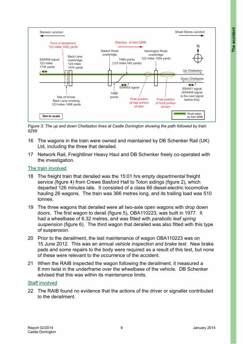
Figure 3: The up and down Chellaston lines at Castle Donington showing the path followed by train 6Z68
N
Route taken by train 6Z68Not to scale
Direction of train 6Z68
Sheet Stores JunctionStenson Junction
Down Chellaston
Up Chellaston
SS4453 signal SS4451 signal (SS4449 signal
is the next signal before this)
SS4458 signal 123 miles 1745 yards
748B points
748A points (123 miles 540 yards)
Station Road overbridge
Site of former Back Lane crossing
123 miles 1488 yards
Back Laneoverbridge123 miles1474 yards
Final position of rear portion
of train
Hemington Road overbridge
122 miles 1554 yards
Final position of front portion
of train
Point of derailment 123 miles 1502 yards
16 The wagons in the train were owned and maintained by DB Schenker Rail (UK) Ltd, including the three that derailed.
17 Network Rail, Freightliner Heavy Haul and DB Schenker freely co-operated with the investigation.
The train involved18 The freight train that derailed was the 15:01 hrs empty departmental freight
service (figure 4) from Crewe Basford Hall to Toton sidings (figure 2), which departed 126 minutes late. It consisted of a class 66 diesel-electric locomotive hauling 26 wagons. The train was 366 metres long, and its trailing load was 510 tonnes.
19 The three wagons that derailed were all two-axle open wagons with drop down doors. The first wagon to derail (figure 5), OBA110223, was built in 1977. It had a wheelbase of 6.32 metres, and was fitted with parabolic leaf spring suspension (figure 6). The third wagon that derailed was also fitted with this type of suspension.
20 Prior to the derailment, the last maintenance of wagon OBA110223 was on 15 June 2012. This was an annual vehicle inspection and brake test. New brake pads and some repairs to the body were required as a result of this test, but none of these were relevant to the occurrence of the accident.
21 When the RAIB inspected the wagon following the derailment, it measured a 6 mm twist in the underframe over the wheelbase of the vehicle. DB Schenker advised that this was within its maintenance limits.
Staff involved22 The RAIB found no evidence that the actions of the driver or signaller contributed
to the derailment.
The
acci
dent

Report 02/2014Castle Donington
10 January 2014
Figure 5: The first wagon to derail, OBA110223
Direction of travel
Figure 4: Train 6Z68, the day following the derailment. Hemington Road overbridge (figure 3) can be seen in the background
The accident

Report 02/2014Castle Donington
11 January 2014
Figure 6: Parabolic leaf spring suspension
23 The section manager (track)2 and his team based at Trent (figure 2) were responsible for the maintenance of the track through Castle Donington and for compliance with the relevant Network Rail standards on track maintenance. The section manager had worked in permanent way since 1987 and in his current post since March 2011. He reported to the Leicester track maintenance engineer within the East Midlands Route infrastructure maintenance director’s organisation.
24 The track maintenance engineer had worked in railway civil engineering in many different roles since 1978. He had been in his current role for three years but had only become responsible for the Trent section a year earlier following a reorganisation.
25 The track maintenance engineer and his team were deemed by Network Rail to have the necessary qualifications within Network Rail’s competence management system to inspect and maintain the track in the area for which they were responsible. However, it was found that a team leader did not hold the qualification required to remove an emergency speed restriction. This is covered later in this report (paragraph 87), but the RAIB has no evidence that it was a factor in the derailment.
2 Referred to as the section manager from here on.
The
acci
dent

Report 02/2014Castle Donington
12 January 2014
26 The Route asset manager (track) and his team was a separate organisation within the East Midlands Route reporting to the director of Route asset management. They were responsible for the long term management of track condition and for controlling the budget covering renewal of the permanent way.
External circumstances27 The weather was cold and clear with a frost. The ground was covered with snow,
and it was dark at the time of the accident. The weather conditions did not affect the occurrence of the accident.
Events preceding the accident28 During the evening of 10 January 2013, the driver of train 6Z96 reported that he
experienced rough riding while passing through Castle Donington in the same direction of travel on the up Chellaston line. This was the same driver that drove train 6Z68 on 21 January 2013. He reported this to the signaller at the East Midlands Control Centre when he stopped at the next signal and described the locomotive as having ‘bottomed out’. He said the location was about 30 to 40 yards (about 27 to 37 metres) beyond signal SS4458 (ie in his direction of travel) and roughly at the location of Back Lane overbridge (figure 3). The conversation was concluded with the driver agreeing with the signaller that the location was 40 to 50 yards (about 37 to 46 metres) beyond signal SS4458.
29 Following the initial report of rough riding by the driver of train 6Z96, the driver of the following freight train, reporting number 6E66, was asked by the signaller at the East Midlands Control Centre to examine the line by driving at slow speed through the section. This driver was unable to confirm the rough riding report made by the driver of train 6Z96.
30 At the East Midlands Control Centre, the shift signalling manager reported to the incident controller that the rough riding had been reported 50 yards (about 46 metres) beyond signal SS4458 and was adjacent to the new Castle Donington distribution centre, just down from the old Back Lane level crossing (figure 3).
31 The incident controller contacted the on-call team leader in the section manager’s organisation who was already responding to a reported fault on the down Chellaston line. He did not take the details of the reported rough ride on the up Chellaston line because he was driving. The section manager (who was also responding to the fault on the down Chellaston line) subsequently phoned the incident controller and was advised that the rough ride on the up Chellaston line was at approximately 123 miles 1694 yards (about 46 metres beyond signal SS4458).
32 In the darkness, the section manager and the team leader were unable to identify any defect at the location reported and normal operations were resumed. They arranged for a maintenance team to attend the following day, which undertook measured shovel packing and kango packing of the track to correct a top defect. This was about 150 metres before the point in the track where the derailment later occurred, and about 70 metres beyond the location of signal SS4458.
The accident
Report 02/2014Castle Donington
13 January 2014
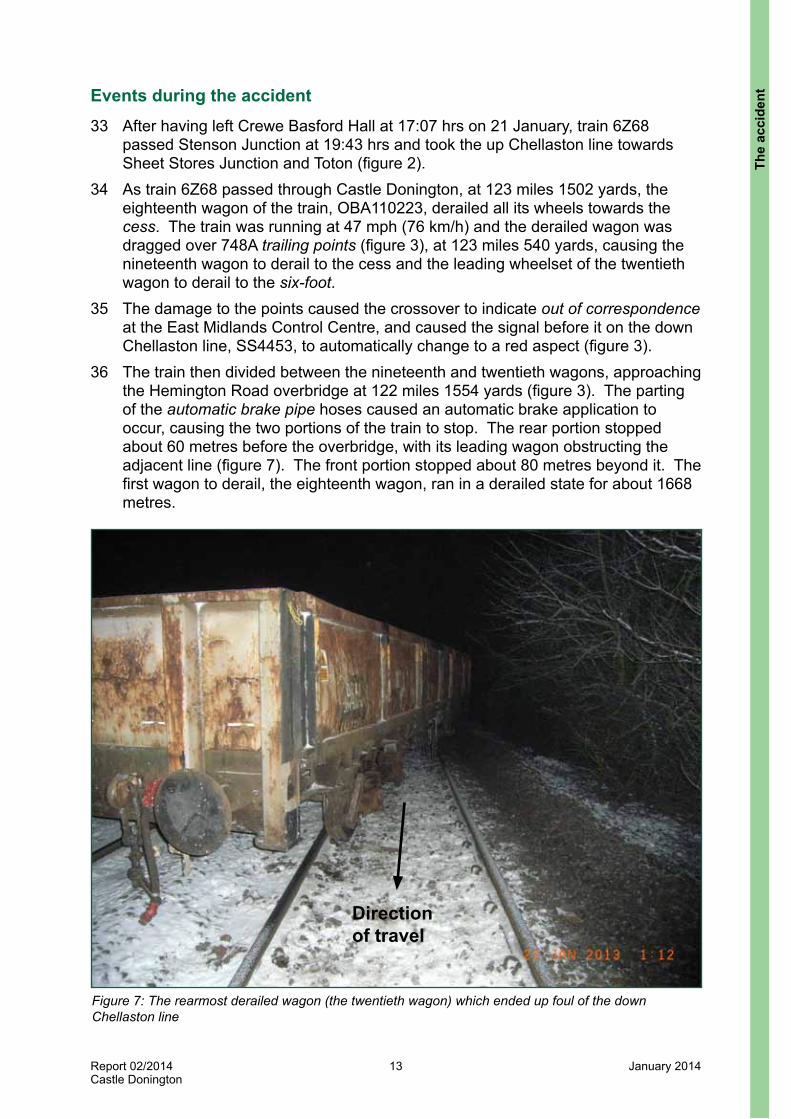
Figure 7: The rearmost derailed wagon (the twentieth wagon) which ended up foul of the down Chellaston line
Direction of travel
Events during the accident 33 After having left Crewe Basford Hall at 17:07 hrs on 21 January, train 6Z68
passed Stenson Junction at 19:43 hrs and took the up Chellaston line towards Sheet Stores Junction and Toton (figure 2).
34 As train 6Z68 passed through Castle Donington, at 123 miles 1502 yards, the eighteenth wagon of the train, OBA110223, derailed all its wheels towards the cess. The train was running at 47 mph (76 km/h) and the derailed wagon was dragged over 748A trailing points (figure 3), at 123 miles 540 yards, causing the nineteenth wagon to derail to the cess and the leading wheelset of the twentieth wagon to derail to the six-foot.
35 The damage to the points caused the crossover to indicate out of correspondence at the East Midlands Control Centre, and caused the signal before it on the down Chellaston line, SS4453, to automatically change to a red aspect (figure 3).
36 The train then divided between the nineteenth and twentieth wagons, approaching the Hemington Road overbridge at 122 miles 1554 yards (figure 3). The parting of the automatic brake pipe hoses caused an automatic brake application to occur, causing the two portions of the train to stop. The rear portion stopped about 60 metres before the overbridge, with its leading wagon obstructing the adjacent line (figure 7). The front portion stopped about 80 metres beyond it. The first wagon to derail, the eighteenth wagon, ran in a derailed state for about 1668 metres.
The
acci
dent

Report 02/2014Castle Donington
14 January 2014
Events following the accident 37 When the train was stopped, following the automatic brake application, the driver
assumed that this was caused by the automatic brake pipe hoses between two wagons becoming parted causing the air to vent and the brakes to apply. He was not aware that any derailment had occurred. Therefore, he did not (and was not required to) switch on the locomotive’s hazard lights.
38 Train 5H74, an empty diesel multiple unit, was approaching Castle Donington on the down Chellaston line and was stopped by the signaller at signal SS4449 (figure 3). At 20:02 hrs, its driver contacted the signaller who advised he was being held at the signal as a precaution because of train 6Z68 standing on the up Chellaston line and the crossover points indicating out of correspondence. At this stage, the signaller did not know the reason for this and had not been contacted by the driver of train 6Z68.
39 The driver of train 6Z68 attempted to walk down the train on the cess side to investigate the cause of the brake application but found his way blocked by lineside vegetation. Therefore, at 20:03 hrs, he contacted the signaller and first explained that the brake had applied and then added that this had occurred after having travelled over a rough piece of track in the same location that was the subject of his previous report on 10 January 2013 (paragraph 28). The driver also explained that he could not get along the cess to examine his train. In response, the signaller blocked the down Chellaston line ahead of signal SS4449, to prevent any train approaching, so that the driver could safely complete his examination from the down Chellaston line.
40 At 20:15 hrs, the driver contacted the signaller again and advised that he had found that the train had become divided and derailed, and that it was obstructing the adjacent line.
The accident

Report 02/2014Castle Donington
15 January 2014
The investigation
Sources of evidence41 The following sources of evidence were used:
l witness interviews and internal staff reports;l data from the train’s on-train data recorder;l data from Control Centre of the Future;l site photographs and measurements, including a survey of the track geometry;l data recorded by Network Rail’s track geometry recording trains;l track geometry data recorded by a stoneblower machine;l Network Rail’s maintenance records of track inspections and work at Castle
Donington;l examination of the derailed wagons’ wheelsets and suspension, particularly the
first wagon to derail;l a review of previous RAIB investigations that had relevance to this accident;l maintenance records for the derailed wagons; andl voice recordings of post-accident communications.
The
inve
stig
atio
n

Report 02/2014Castle Donington
16 January 2014
Key facts and analysis
Background informationMethods of restoring track top42 Track top, or vertical geometry, is required to be sufficiently smooth to allow trains
to pass safely along the track at the maximum permissible speed of the line. Over time, the top deteriorates unless it is subject to maintenance work to correct it. This maintenance can be by manual means, known as lifting and packing, or by mechanised means using an on-track machine.
43 Shovel packing is a relatively quick method of lifting and packing to improve track top. It entails staff packing the track by first lifting it with jacks and then using shovels to move pieces of stone forming the ballast under the sleepers. However, the top deteriorates rapidly as the pieces of stone moved under the sleepers get pushed down under the weight of passing rail traffic. The principle of kango packing is the same but uses vibrating hammers to pack ballast more effectively under the sleepers.
44 The guidance to staff on lifting and packing published in the form of Track Work Information Sheets under Network Rail’s guidance note NR/GN/TRK/7001, includes the information that shovel packing is the least preferred option for packing sleepers. The same information sheets state that kango packing is the preferred method where the ballast is in good condition, but is unsuitable for use where the ballast is contaminated.
45 Measured shovel packing is a more durable method than shovel packing because it uses measured quantities of small chippings to fill the voids rather than the larger pieces of ballast used in the shovel packing method. However, it takes more time to carry out because any voids have to be measured first.
46 Track top can be restored by mechanised means either by using a tamping machine or a stoneblower. A tamping machine corrects top, and any deficiencies in horizontal alignment, by lifting the track and compacting the ballast beneath the sleepers. Stoneblowers work by lifting the track and injecting calculated quantities of stone chippings under the sleepers. The rails and sleepers are than lowered back onto the chippings, which consolidate under traffic. Stoneblowing is a more effective method than tamping when the underlying track formation is in poor condition.
Track inspections47 Network Rail maintenance staff are responsible for inspecting the track in
accordance with Network Rail company standard NR/L2/TRK/001, ‘Inspection and Maintenance of Permanent Way’. The regime consists of visual inspections and inspections by a track geometry recording train.
Key facts and analysis

Report 02/2014Castle Donington
17 January 2014
48 Standard NR/L2/TRK/001 requires inspection of the up and down Chellaston lines:l every 2 weeks (maximum interval 17 days) by maintenance staff on foot (basic
visual inspections);l every 16 weeks (maximum interval 20 weeks) by a supervisor on foot;l every 26 weeks (maximum interval 32 weeks) by a supervisor from the cab of a
train;l every year (maximum interval a year and 8 weeks) by the track maintenance
engineer from the cab of a train; andl every 2 years (maximum interval 2 years and 16 weeks) by the track
maintenance engineer on foot.49 The inspection records provided to the RAIB showed that the line through Castle
Donington was inspected fortnightly in accordance with standard NR/L2/TRK/001. A patroller carried out these basic visual inspections by walking on either the up Chellaston line or the down Chellaston line on an alternating basis. This meant that during any patrol he could only observe the other line (which would be open to traffic) from across the six-foot.
50 The inspection records also showed that the supervisor’s and track maintenance engineer’s inspections were in accordance with standard NR/L2/TRK/001, apart from those relating to inspections from the cab of a train, which had not been done. This was reported to be because of the difficulty in arranging cab rides on a railway with no timetabled passenger trains. The RAIB does not believe that this was a factor in the derailment.
Cyclic top and its detection51 Cyclic top is a regular series of alternate high and low spots in a track. At certain
speeds, this can cause resonance in the suspension of some types of rail vehicles. In extreme cases, the bouncing motion set up can cause the vehicle to derail when one of the wheels becomes unloaded allowing its flange to climb onto and over the rail head.
52 The high and low spots in the track which combine to make up cyclic top may not be seen during a visual inspection because of voids under the sleepers. As a train passes over voids, its weight depresses the track to fill them and they then reform afterwards. This may cause the track geometry to appear to be acceptable visually, but exhibit cyclic top under load.
53 The only reliable means to identify and measure the severity of cyclic top is by running a track geometry recording train over the section of line. Network Rail planned a track geometry recording train to run over each of the up and down Chellaston lines every 24 weeks. This analyses the measured track geometry and looks for evidence of cyclic top. If allowable limits are exceeded, a track geometry fault is recorded requiring action to be taken to correct the fault either immediately (an immediate action limit fault), or within a defined timescale (an intervention limit fault)3.
3 These are often referred to as Level 2 faults.
Key
fact
s an
d an
alys
is

Report 02/2014Castle Donington
18 January 2014
54 The output from a track geometry recording train is a report listing the faults identified and a track geometry trace. These are sent to the part of Network Rail responsible for maintaining that section of line so that the section manager can implement the required action.
55 Network Rail’s standard NR/L2/TRK/001/mod11, ‘Track Geometry Inspections and Minimum Actions’ lists the minimum actions to be taken following the detection of track geometry faults. In the case of cyclic top where the permissible speed is 30 mph (48 km/h) or above, immediate action is triggered by the detection of sequential top faults, which may not individually breach track geometry limits, but at least one of which is 30 mm or more in one rail, or 50 mm or more in both rails. The action required is the immediate imposition of a 30 mph (48 km/h) emergency speed restriction, followed by remedial action within 36 hours.
56 Standard NR/L2/TRK/001/mod11 also lists intervention limits for cyclic top requiring action to less urgent timescales. This varies, from the implementation of a 30 mph (48 km/h) emergency speed restriction within 36 hours and remedial action within 14 days, to no requirement for an emergency speed restriction but remedial action within 60 days.
57 The RAIB reviewed previous records from runs of track geometry recording trains along the up Chellaston line. During the five years before the derailment it found that cyclic top in the vicinity of the point of derailment, which exceeded the intervention action limits in standard NR/L2/TRK/001/mod11, was first recorded on 24 May 2010.
58 The records show that in response, measured shovel packing and tamping were carried out such that by the time of the next run of a track geometry recording train on 1 November 2010, there were no reportable defects identified in the vicinity of the point of derailment, and the geometry trace shows that the top was much improved.
59 The track geometry recording train runs did not identify a recurrence of cyclic top faults until the run on 29 May 2012. Network Rail standards required a 30 mph (48 km/h) emergency speed restriction to be imposed and the defects to be corrected within 14 days. The defects extended over a distance from 123 miles 1609 yards to 123 miles 1461 yards on the up Chellaston line. The emergency speed restriction was imposed and measured shovel packing was carried out so that by the time of the next run of a track geometry recording train on 23 June 2012, only less serious cyclic top faults, requiring action within 60 days, were identified. This indicated that the work done in response to the previous run was partially effective. The run on 23 June 2012 was followed by further work, including two instances of measured shovel packing, intended to rectify cyclic top.
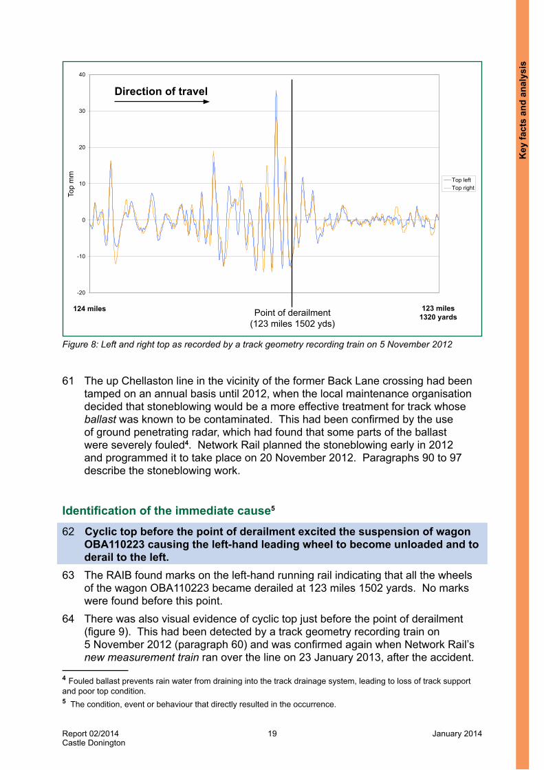
60 On 5 November 2012 the track geometry recording train reported cyclic top faults requiring immediate action in the vicinity of the former Back Lane level crossing (figure 3), between 123 miles 1521 yards and 123 miles 1398 yards; and just under 200 yards before Hemington Road bridge (figure 3), between 123 miles 129 yards and 122 miles 1741 yards. Figure 8 shows the condition of the track top in the vicinity of where the derailment occurred. The severity of the faults required the immediate implementation of an immediate 30 mph (48 km/h) emergency speed restriction, followed by action to remove the faults within 36 hours. Paragraphs 79 to 89 describe the work undertaken by Network Rail in response.
Key facts and analysis
Report 02/2014Castle Donington
19 January 2014
Figure 8: Left and right top as recorded by a track geometry recording train on 5 November 2012
Top from 124 miles to 123 miles 60 ch as measured by TRV on 5 November 2012
-20
-10
0
10
20
30
40m
m Top leftTop right
Direction of travel
Point of derailment (123 miles 1502 yds)
123 miles 1320 yards
124 miles
Top
mm
61 The up Chellaston line in the vicinity of the former Back Lane crossing had been tamped on an annual basis until 2012, when the local maintenance organisation decided that stoneblowing would be a more effective treatment for track whose ballast was known to be contaminated. This had been confirmed by the use of ground penetrating radar, which had found that some parts of the ballast were severely fouled4. Network Rail planned the stoneblowing early in 2012 and programmed it to take place on 20 November 2012. Paragraphs 90 to 97 describe the stoneblowing work.
Identification of the immediate cause5 62 Cyclic top before the point of derailment excited the suspension of wagon
OBA110223 causing the left-hand leading wheel to become unloaded and to derail to the left.
63 The RAIB found marks on the left-hand running rail indicating that all the wheels of the wagon OBA110223 became derailed at 123 miles 1502 yards. No marks were found before this point.
64 There was also visual evidence of cyclic top just before the point of derailment (figure 9). This had been detected by a track geometry recording train on 5 November 2012 (paragraph 60) and was confirmed again when Network Rail’s new measurement train ran over the line on 23 January 2013, after the accident.
4 Fouled ballast prevents rain water from draining into the track drainage system, leading to loss of track support and poor top condition.5 The condition, event or behaviour that directly resulted in the occurrence.
Key
fact
s an
d an
alys
is

Report 02/2014Castle Donington
20 January 2014
65 Network Rail’s derailment investigation team undertook a dynamic analysis to understand the contribution of cyclic top to the derailment. This predicted that the excitation frequencies from the series of 7-11 metre wavelengths in the track top starting 30 metres before the point of derailment, when traversed at 50 mph (80 km/h), were close to the wagon’s bounce and roll resonant frequencies. They were sufficient to cause the vertical load on the left-hand wheel to reduce to such an extent that a low lateral force would cause it to derail. The analysis concluded that the derailment was caused by cyclic top.
66 The RAIB did a simplified comparison between input frequency and the natural frequency of the wagon, which supported Network Rail’s conclusions.
67 Previous studies6 have identified that empty four-wheel wagons fitted with parabolic leaf spring suspension (such as OBA110223 - paragraph 19) are at greater risk of derailment while running on poor quality track with cyclic top than wagons with other suspension types, because parabolic leaf spring suspension has high vertical stiffness and low damping. Consequently, when travelling at certain speeds, wagons with this type of suspension can be excited by the wavelengths of cyclic top faults. This can cause a bouncing effect and consequent wheel unloading.
Identification of causal factors7 68 The routine inspection and maintenance of the up Chellaston line at Castle
Donington did not maintain the track top to avoid a recurrence of cyclic top faults. This was a causal factor.
Visual inspections69 Following work done in response to cyclic top reports from a track
geometry recording train on 5 November 2012 and stoneblowing on 20 November 2012, further cyclic top was not visually identified for remedial action before the derailment occurred.
70 While cyclic top may sometimes be identified by eye, its severity can only be established by measurements taken by a track geometry recording train (paragraph 52). This is a possible further factor in the derailment because in practice maintenance staff rely on the track geometry recording train to identify cyclic top for remedial action.
71 Track geometry recording trains had identified cyclic top in the vicinity of the derailment that required remedial action on previous occasions (paragraphs 57 to 60). The general area therefore had a history of this type of defect occurring.
72 Cyclic top was clearly visible just before the point of derailment when the RAIB attended the derailment site (figure 9).
6 l ‘Cost-effective reduction of derailment risk’ report T357, January 2006, www.rssb.co.uk. l ‘An investigation of derailment risk associated with cyclic top’, report RR-DYN-95-132, 13 October 1995, British
Rail Research7 Any condition, event or behaviour that was necessary for the occurrence. Avoiding or eliminating any one of these factors would have prevented it happening.
Key facts and analysis

Report 02/2014Castle Donington
21 January 2014
Figure 9: Cyclic top on the up Chellaston just before the point of derailment on the day following the derailment
Direction of travel
SS4458 Signal
73 The last basic visual inspection by a patroller before the derailment was on 17 January 2013 and was from the down Chellaston line. The last inspection from the up line was on 3 January 2013. Neither of these inspections reported any cyclic top in the Back Lane area. In fact, over the previous five months, none of the reports from basic visual inspections on foot referred to cyclic top.
74 The patroller who did the last basic visual inspection before the derailment stated that his initial training in 2011 included instruction in how to recognise cyclic top. Under standard NR/L2/TRK/001, cyclic top is one of the types of defects that a patroller should observe. However, the focus of a basic visual inspection is mainly on the identification of defects that are immediately dangerous, or are likely to see rapid deterioration before the next basic visual inspection. Cyclic top would also have been difficult to detect from a standing/walking position; it is necessary to get down to rail level to see it.
75 Although the patroller was part of the work team which did the shovel packing on 9 November 2012 (paragraphs 79 to 89), he stated that in general he was not made aware of the results of the track geometry recording train runs, or any action taken in response to them. He did not look specifically at locations where there had been cyclic top reported, or monitor any deterioration following repairs.
76 On 8 November 2012, the section manager did the last supervisor’s inspection (see paragraph 48) before the derailment occurred from the up Chellaston line, and he did not make any observations, or record any required actions, for the track in the vicinity of the derailment. However, the section manager was aware that the track in the Back Lane area was to be shovel packed the following day in response to the cyclic top reports from the track geometry recording train run of 5 November 2012 and this may have influenced what he observed and recorded.
Key
fact
s an
d an
alys
is

Report 02/2014Castle Donington
22 January 2014
77 The track maintenance engineer did a routine inspection on 17 January 2013 (with the patroller who was carrying out the basic visual inspection) and identified a defect in the track top in the up Chellaston line at 123 miles 1500 yards that appeared to exceed Network Rail’s track geometry limits. This is likely to have been the top fault of around 30 mm magnitude shown in figure 8. The track maintenance engineer booked remedial action to be taken within a month. He did not record the cyclic top in the vicinity of the derailment.
78 It is possible that the track maintenance engineer did not record the cyclic top for remedial action because he was carrying out his inspection from the adjacent down Chellaston line and was not in a good position to observe cyclic top on the up Chellaston line. He was aware that there had been a cyclic top problem at this location and had the results of the last run of the track geometry recording train on 5 November 2012 with him, which he used as a reference. However, his evidence was that he was not aware the stoneblowing had not been completed on 20 November 2012 (paragraph 90), and he may therefore have believed that the previous cyclic top defect had been corrected.
Work done in response to cyclic top faults reported by a track geometry recording train on 5 November 201279 The lifting and packing carried out in response to the track geometry
recording train run on 5 November 2012 was insufficient to eliminate the cyclic top present on any long term basis.
80 Following the cyclic top faults recorded by the track geometry recording train in the vicinity of the old Back Lane crossing and Hemington Road bridge on 5 November 2012 (paragraph 60), staff from the section manager’s team imposed a 30 mph (48 km/h) emergency speed restriction later that day.
81 The section manager arranged for a work team of six staff to carry out remedial action on Friday 9 November 2012. Although this was later than the 36 hours required for the correction of the defects, the section manager misunderstood the procedure and was under the impression that this extended timescale was acceptable once the emergency speed restriction had been imposed.
82 The section manager gave evidence that he told the team leader to use the shovel packing or kango packing methods (paragraph 43), as there was too much work to use the measured shovel packing method. The section manager was aware that the same section of line was planned to be stoneblown on 20 November 2012, so the work done would only have been required to last until then (provided the stoneblowing was completed as planned – paragraphs 90 to 97).
83 According to the records, the team leader arranged for the up Chellaston line to be blocked to train movements so the work could be done from 08:49 hrs. The work team attended the Hemington Bridge site first and then the Back Lane site. The team leader identified the high spots and the number of cycles by eye based on the overall distance reported by the track geometry recording train. He considered that the number of personnel present was about right for the work they had to do, and they used the shovel packing method to lift and pack the track. The team was unable to use the kango packing method because they were not competent in its use. However, given that the ballast in the Back Lane area was contaminated (paragraph 61), kango packing may not have been the most appropriate method.
Key facts and analysis

Report 02/2014Castle Donington
23 January 2014
84 Track Work Information Sheets 2T012 and 2T013, listed in guidance note NR/GN/TRK/7001 (paragraph 44), state that after lifting and packing has been undertaken, the track should be checked after the passage of trains because the ballast may settle unevenly. Monitoring the track while a train passes over it and measurement afterwards is necessary to establish whether any settlement as a result of the newly packed stones being pushed down under the weight of a train is acceptable.
85 The records show that the blockage of the line was given up at 12:26 hrs and although, according to witness evidence, long gaps in traffic can occur on this line, the next train passed along the up Chellaston line at 13:17 hrs.
86 The team leader provided evidence that he was still in the vicinity when a train passed on the up Chellaston line (which was presumably the one at 13:17 hrs), but that he was not there to observe the passage of a train or to check the track afterwards. There is no evidence that the train’s passage was specifically observed, or that any measurements were taken afterwards. The likelihood that the effects of the passage of a train on the shovel packing were not checked is a possible further factor in the derailment.
87 The team leader removed the emergency speed restriction that had been applied on 5 November 2012. Although the team leader had over 20 years experience in track maintenance and the records showed that he was qualified to restore track geometry by manual repair, and to confirm track is fit for operational purposes following maintenance repair, he was not qualified to remove emergency speed restrictions.
88 The team leader should have been qualified in accordance with the requirements of Network Rail standard NR/L2/TRK/001/mod13 ‘Confirming track is safe for selected line speed after work’. However, according to witness evidence, the requirements of the standard were not properly understood within the Trent section manager’s organisation. To obtain the additional qualification the team leader should have attended a course covering how to inspect the line to ensure it is safe at the higher speed, and then have been mentored and passed out as competent. There is a requirement under the standard to formally document the process of raising the speed by completing and signing off track engineering form TEF3203 ‘Infrastructure Conformance Certificate’. This was not completed.
89 It is possible that the requirements of the additional qualification to inspect the line and formally document the process of raising the speed limit may have led to different actions on the day the work was done. This is a further possible further factor in the derailment.
Stoneblowing on 20 November 201290 The stoneblowing in the Hemington Road bridge and Back Lane areas on
20 November 2012 did not cover the location of the cyclic top which caused the derailment because it was terminated early and was not subsequently planned to be completed.
91 Not all the planned work was completed during the stoneblowing on 20 November 2012 due to there being insufficient time. The stoneblowing stopped before it reached the point of derailment (figure 10). There being insufficient time to complete the stoneblowing is a further factor in the derailment.
Key
fact
s an
d an
alys
is

Report 02/2014Castle Donington
24 January 2014
Figure 10: Plot of track top showing the shovel packing carried out on 9 November 2012 and the stoneblowing on 20 November 2012 against the track recording trace of 5 November 2012 (POD = Point of derailment: 123 miles 1502 yds)
-30
-20
-10
0
10
20
30
40
Left topRight top
Direction of travel
POD
Area of shovel packing 9 November 2012 Achieved stoneblowing
Planned stoneblowing
124 miles 123 miles 1320 yds
123 miles 880 yds
123 miles 440 yds
123 miles
Top
mm
92 The plan was to stoneblow two separate sites: the first (deemed by the section manager to be of higher priority) was near the Hemington Road overbridge (figure 3), from 123 miles 550 yards to 122 miles 1584 yards; the second was in the Back Lane area from 124 miles 0 yards to 123 miles 704 yards. In the event, the first site was completed as planned, but the records show that only 220 yards of the second site was stoneblown, from 124 miles 0 yards to 123 miles 1540 yards. This distance included ramping in and ramping out in which the amount of stone blown increases/reduces in order to provide a smooth transition with the untreated track. The work therefore stopped before reaching the point of derailment at 123 miles 1502 yards.
93 The stoneblowing had been planned by the planner in the track maintenance engineer’s organisation about six months earlier, based on the normal possession lengths on the Sheet Stores Junction to Stenson Junction route. However, in the event, the possession finish time was about an hour and a half earlier than normal due to planned engineering work taking place elsewhere. The stoneblowing was not replanned when this became known some weeks before 20 November 2012. The RAIB has been unable to establish why this was not done. The absence of any replanning of the work after it became apparent that the possession length would be shorter than expected is a further factor in the derailment.
94 The track quality supervisor in charge of the stoneblowing activity on the night did not know why the track was being stoneblown, or the implications of not completing all the planned work for the safety of train movements afterwards. At the end of the work, the track quality supervisor notified the section manager of what had been completed, highlighting the shortfall.
Key facts and analysis

Report 02/2014Castle Donington
25 January 2014
95 The following day, the section manager visited the site and, on the basis of a visual inspection, decided that the stoneblowing that had been completed was sufficient because the condition of the track which had not been stoneblown appeared to be satisfactory. It is possible that at this time the shovel packing done on 9 November 2012 was still effective, and any poor top, or the effect of any voiding, was not apparent (figure 9). Alternatively, the track that had been shovel packed could have already deteriorated, but the section manager did not detect the cyclic top present by eye.
96 As a consequence of the section manager’s inspection, the track that had not been stoneblown in the lead up to the point of derailment was not replanned to be stoneblown at a later date, or to have any other remedial action taken to deal with underlying cyclic top. This is a further factor in the derailment.
97 Two days after the derailment, Network Rail arranged for a track geometry recording train to run over the up Chellaston line. This reported immediate action limit cyclic top faults in the area of the point of derailment. The recording of the top showed the effect of the stoneblowing (figure 11). Figure 11 also shows that there was poor top between where the stoneblowing was completed and the point of derailment, indicating that, by this time, and following the passage of many trains, the shovel packing done on 9 November 2012 was no longer effective. Figures 12a and 12b show a comparison of the track top on 5 November 2012 and 23 January 2013.
-20
-10
0
10
20
30
40
Top
mm
Left topRight top
Direction of travel
Point of derailment (123 miles 1502 yds)
Top
mm
123 miles 1320 yards
124 miles
Stoneblown, 20/11/2012
Figure 11: Track top following the derailment as measured on 23 January 2013
Key
fact
s an
d an
alys
is

Report 02/2014Castle Donington
26 January 2014
Figure 12a: Comparison of right top 5 November 2012 and 23 January 2013
-20
-10
0
10
20
30
40
Right top 5 Nov 2012Right top 23 Jan 2013
Point of derailment (123 miles 1502 yds)
Direction of travel
123 miles 1320 yards
124 miles
Top
mm
Stoneblown, 20/11/2012
Figure 12b: Comparison of left top 5 November 2012 and 23 January 2013
-20
-10
0
10
20
30
40
Left top 5 Nov 2012Left top 23 Jan 2013
Direction of travel
123 miles 1320 yards
124 miles
Top
mm
Stoneblown, 20/11/2012
Point of derailment (123 miles 1502 yds)
Key facts and analysis

Report 02/2014Castle Donington
27 January 2014
The driver’s report of rough riding on 10 January 201398 The location of the rough ride as reported by the driver on 10 January 2013
was not correctly advised to maintenance staff so their focus in carrying out remedial work may not have been on the correct location.
99 On 10 January 2013, the driver of train 6Z96 reported rough riding (describing the locomotive as ‘bottoming out’) to the signaller in the vicinity of the point of derailment (paragraphs 28 to 32). The driver reported it to be between 30 to 40 yards (about 27 to 37 metres) ahead of signal SS4458, located at 123 miles 1745 yards, and roughly at the Back Lane overbridge at 123 miles 1474 yards (figure 3) (ie within a range of about 271 yards (248 metres)). By the time the message was passed to the section manager, he was advised that the location was at 123 miles 1694 yards.
100 In response, the section manager and a team leader examined the up Chellaston line from the site of the old Back Lane crossing (123 miles 1488 yards) to the location of signal SS4458 the same evening, but it was done in darkness when cyclic top would not have been visible. The section manager arranged for a maintenance team to attend the following day, which carried out lifting and packing about 150 metres before the point of derailment where there was a definite top fault. This was about 72 metres beyond signal SS4458. The nature of the driver’s report of the locomotive ‘bottoming out’ suggested a discrete fault, but it is not known whether the lifting and packing covered the defect felt by the driver.
101 The information reported to the section manager may have led to the maintenance staff focussing their attention close to signal SS4458, rather than over the full distance reported by the driver, and not investigating whether there was cyclic top in the area. This is a further factor.
Identification of underlying factors8 102 The ballast supporting the track was fouled causing inadequate track
support and repeated cyclic top. This was an underlying factor.103 In the area of the derailment, the ballast was in a poor condition and subject to
rapid deterioration because of poor drainage, probably exacerbated by the wet weather in the latter part of 2012. This would have made it more difficult for the maintenance staff to maintain the track in an acceptable condition.
104 The degree of contamination of the ballast was measured by ground penetrating radar from a maintenance train on 5 April 2012 (it had also been measured in 2011 and in 2009). Network Rail uses this technique as a means to provide supporting information for renewals proposals. The ballast fouling index is derived from the radar results, and for around 100 yards leading to the point of derailment, the index was generally in the ‘fouled’ to ‘severely fouled’ region below 100 mm of ballast depth. According to Network Rail standard NR/L2/TRK/2102 ‘Design and Construction of Track’ for the route through Castle Donington, there should be a minimum of 250 mm depth of clean ballast under track that is continuously welded on concrete sleepers.
8 Any factors associated with the overall management systems, organisational arrangements or the regulatory structure.
Key
fact
s an
d an
alys
is

Report 02/2014Castle Donington
28 January 2014
105 When the track maintenance engineer routinely inspected the line on 3 February 2011, he noted that on the up Chellaston line between 123 miles 1430 yards and 124 miles 0 yards there was ‘poor top due to small ballast, no drainage’ and that a proposal should be submitted for drainage works and reballasting.
106 The RAIB was unable to find evidence that any such proposal for drainage works and reballasting was subsequently made to the Route asset manager, but there was no evidence that this omission made the derailment more likely.
107 Drainage works were carried out in August 2012 after funding became available through the Office of Rail Regulation in 2011/12 for a national programme of works to improve drainage, and track maintenance engineers were asked where the money should be spent.
108 The drainage works consisted of lowering the cess, to improve the run off of water, between 123 miles 1540 yards and 123 miles 1720 yards. This work would not have had any effect on the contaminated ballast and did not extend through to the point of derailment. Beyond 123 miles 1540 yards, through the point of derailment, there was drainage in the six-foot but witness evidence suggested that this was blocked when the derailment occurred.
109 The reballasting required was put into the renewals programme for 2016/17 as the result of a review of desired work across the East Midlands Route by the Route asset manager (track), with the track maintenance engineers. Had the track maintenance engineer’s proposal from his inspection on 3 February 2011 been actioned, it seems unlikely that the reballasting would have been carried out before the derailment occurred.
110 Witness evidence was that the extended timescale for the reballasting was because of Network Rail’s track asset policy for the route through Castle Donington. This was that the track condition was to be sustained through maintenance with minimal renewals. The purpose of such a policy is to ensure that priority is given to the more important routes where speeds are higher and which also carry passenger trains. Witness evidence suggested that with the improvements to drainage allowing the track to dry out, and annual tamping/stoneblowing, it was considered that the track would remain in an acceptable condition until the reballasting planned in 2016/7.
111 The weather records show that for England as a whole, 2012 was the wettest year on record (since 1910) even though the first three months were drier than normal. December was the fourth wettest month of the year. In the Castle Donington area, the December rainfall total was the highest since 1989, and almost double the December monthly average over the past 50 years. The wet weather is likely to have increased the rate of deterioration of the Castle Donington route, particularly between the track geometry recording train run of 23 June 2012 (paragraph 59), in which the track condition in the Back Lane area only gave rise to minor faults being reported, and the derailment occurring.
Key facts and analysis

Report 02/2014Castle Donington
29 January 2014
Observations9
Abnormal brake applications112 It is possible that an approaching train could have collided with the derailed
wagon of train 6Z68 which was foul of the down Chellaston line if the signaller had not shown vigilance and returned a signal to danger on the adjacent line (paragraph 38).
113 Train 6Z68 stopped as a result of the abnormal brake application which occurred when the train divided. The driver did not know why the brake application had occurred and thought that it was caused by the parting of automatic brake pipe hoses between two vehicles, with no other consequences.
114 The Rule Book (GE/RT8000, module TW1) required that following an abnormal brake application, the driver should first check whether any in-cab equipment intervened to cause the brake application. If this was not the case, the driver should check that the train was complete with a tail lamp. If this was found to be missing, or the air brake pipe found to be open on the rear vehicle, the driver should assume that the train had become divided and carry out the instructions in module M1 of the Rule Book.
115 Module M1 requires that the driver should immediately switch on the hazard warning lights and display a red light facing forward before checking whether other lines are obstructed and advising the signaller.
116 The driver of any other train approaching the scene, in the opposite direction, on sighting the hazard lights and the red light would be required to apply the brakes and stop as quickly as possible.
117 It is likely to take several minutes for a driver to establish whether or not the train is complete, during which time there may be no protection against another train approaching and colliding with vehicles standing foul if a derailment has occurred.
118 The RAIB believes that the rules concerning the contacting of the signaller and the actions to be taken following an abnormal brake application on a freight train should be reviewed, so that any adjacent lines that may be affected are protected as soon as possible.
Occurrences of a similar character119 The RAIB has investigated one previous derailment that was caused by cyclic
top. This was of an ultrasonic test vehicle, a four-wheel vehicle with a short wheelbase, which occurred at Cromore in Northern Ireland (report 42/2007). The vehicle, hauled by a locomotive, was travelling at excessive speed. The RAIB made a recommendation that the suspension of that type of vehicle should be modified to minimise its sensitivity to track irregularities. This was done by fitting softer rubber chevrons to the primary suspension, and hydraulic dampers.
120 At the time of publication, the RAIB was investigating the derailment of a freight train on 15 October 2013 approaching Gloucester, on the line from Newport via Lydney. The RAIB’s examination of the line on the approach to the point of derailment found that it had cyclic top.
9 An element discovered as part of the investigation that did not have a direct or indirect effect on the outcome of the accident but does deserve scrutiny.
Key
fact
s an
d an
alys
is

Report 02/2014Castle Donington
30 January 2014
Summary of conclusions
Immediate cause 121 Cyclic top before the point of derailment excited the suspension of wagon
OBA110223 causing the left-hand leading wheel to become unloaded and to derail to the left (paragraph 62).
Causal factors 122 The routine inspection and maintenance of the up Chellaston line at Castle
Donington did not maintain the track top to avoid a recurrence of cyclic top faults (paragraph 68).Factors contributing to this causal factor are:i. Following work done in response to cyclic top reports from a track geometry
recording train on 5 November 2012 and stoneblowing on 20 November 2012, further cyclic top was not visually identified for remedial action before the derailment occurred. The following are possible further factors:l its severity can only be measured by a track geometry recording train; and l the circumstances associated with the routine inspections of the track
resulted in the cyclic top not being identified as a defect requiring remedial action (paragraphs 69 to 78).
ii. The lifting and packing in response to the track geometry recording train run on 5 November 2012 was insufficient to eliminate the cyclic top present on any long term basis. The following are possible further factors:l not checking for settlement following the passage of a train, after the work
was completed; andl the team leader who removed the emergency speed restriction was not
qualified to do so due to a misunderstanding of the requirements of Network Rail’s standard NR/L2/TRK/001/mod 13 in the Trent section manager’s organisation (paragraphs 79 to 89, Learning Points 1 and 2).
iii. The stoneblowing in the Hemington Road bridge and Back Lane areas on 20 November 2012 did not cover the location of the cyclic top which caused the derailment. The following are further factors:l there was insufficient time to complete the stoneblowing; l the work was not replanned after it became apparent that the possession
length would be shorter than expected; andl the track was not stoneblown as planned and no plan was put in place
to complete the stoneblowing (or to rectify the cyclic top by other means) (paragraphs 90 to 97, Recommendation 1).
iv. The location of the rough ride as reported by the driver on 10 January 2013 was not correctly advised to maintenance staff so their focus in carrying out remedial work may not have been on the correct location. A further factor is that the maintenance team did not investigate whether there was cyclic top in the area (paragraphs 98 to 101, Learning Point 3).
Summ
ary of conclusions

Report 02/2014Castle Donington
31 January 2014
Underlying factors 123 The ballast supporting the track was fouled causing inadequate track support and
repeated cyclic top (paragraph 102).
Additional observations 124 Although not causal to the derailment on 21 January 2013, the RAIB observes
that had the signaller not shown vigilance and returned a signal to danger on the adjacent line, it is possible that an approaching train could have collided with the derailed wagon of train 6Z68 which was foul of the down Chellaston line. This could have occurred because following an abnormal brake application, which may have been caused by the train dividing, the Rule Book requires the driver to check the train is complete before contacting the signaller. This may take several minutes (paragraph 112, Recommendation 2).
Sum
mar
y of
con
clus
ions
Report 02/2014Castle Donington
32 January 2014
Previous RAIB recommendations relevant to this investigationDerailment at Bordesley Junction, Birmingham, 26 August 2011125 The RAIB’s investigation into a freight train derailment at Bordesley Junction
(RAIB report 19/2012, published on 19 September 2012) found that the track on the down main (Bordesley) line close to the junction was not tamped as planned during overnight work on 21/22 August 2011 and that this was a causal factor of the derailment. The area of track where there were track geometry faults was not tamped as planned because the work ran short of time. The track quality supervisors present had not been given any priorities for the work, or specific briefing that they should make sure they tamped the area containing the track geometry faults.
126 Following its investigation, the RAIB made a recommendation which addresses factors also identified in this investigation:Recommendation 4 Network Rail should review and implement changes to its processes for briefing staff responsible for the work carried out by on-track machines, so that their briefings will include information on whether any part of the work should be given priority over another and the reasons for such prioritisation.
127 The Office of Rail Regulation reported to the RAIB in August 2013 that Network Rail was implementing the recommendation and would provide a further update at a later date.
128 The recommendation is relevant to the RAIB’s investigation of the Castle Donington derailment because although the track quality supervisor had been told which of the two sites requiring stoneblowing was the higher priority, he was not aware of the reasons for the prioritisation, or indeed why the stoneblowing was taking place and that cyclic top was a factor (paragraph 94).
Previous RA
IB recom
mendations relevant to this investigation

Report 02/2014Castle Donington
33 January 2014
Actions reported as already taken or in progress relevant to this report129 Two days after the derailment, Network Rail ran a track geometry recording train
over the Castle Donington route (paragraph 97).130 Network Rail brought forward the reballasting of the up Chellaston line in the Back
Lane area to 2013/14. This was completed on 19 August 2013.131 Network Rail’s requirements relating to the competence of those required to raise
speeds have been implemented in the Trent section manager’s organisation (paragraph 87).
Act
ions
repo
rted
as
alre
ady
take
n or
in p
rogr
ess
rele
vant
to th
is re
port

Report 02/2014Castle Donington
34 January 2014
Learning points
132 The RAIB has identified the following key learning points10.
Learning point 1Following the lifting and packing of track, it is important that it is checked after the passage of a train to identify any settlement that may have occurred, and then is closely monitored afterwards to detect any further settlement.
Learning point 2It is important that staff who are required to raise speed restrictions, that have been implemented because of poor track condition, are appropriately qualified under the relevant industry standards to do so.
Learning point 3It is important that when communicating information concerning safety, such as the location of defective track, staff should do so clearly and accurately so that it is understood by both parties and does not change when further communicated to others.
10 ‘Learning points’ are intended to disseminate safety learning that is not covered by a recommendation. They are included in a report when the RAIB wishes to reinforce the importance of compliance with existing safety arrangements (where the RAIB has not identified management issues that justify a recommendation) and the consequences of failing to do so. They also record good practice and actions already taken by industry bodies that may have wider application.
Learning points
Report 02/2014Castle Donington
35 January 2014
Recommendations
133 The following recommendations are made11:
1 The intent of this recommendation is to reduce the risk of derailment if a stoneblower is unable to complete its planned work in the time available.
Network Rail should review, and if necessary improve, the planning of stoneblowing so that:l there is sufficient time allocated within the duration of a possession to
complete the work planned to be carried out; andl if the duration of the possession is reduced after the work has first been
planned, the implications for the completion of the work are examined, and the work re-planned so that the highest priority locations may be completed in the reduced time available (paragraph 122iii).
2 The intent of the recommendation is to reduce the risk of trains colliding with a derailed vehicle.
RSSB, in conjunction with the rail industry, should undertake a review of the Rule Book requirements relating to the action to be taken following an abnormal brake application on a freight train and make any changes found to be necessary to reduce the risk of collision with a derailed vehicle. Such a review should consider under what circumstances and how quickly the signaller should be contacted and the actions to be taken, such as cautioning the first train to pass on the adjacent line (paragraph 124).
11 Those identified in the recommendations, have a general and ongoing obligation to comply with health and safety legislation and need to take these recommendations into account in ensuring the safety of their employees and others. Additionally, for the purposes of regulation 12(1) of the Railways (Accident Investigation and Reporting) Regulations 2005, these recommendations are addressed to the Office of Rail Regulation to enable it to carry out its duties under regulation 12(2) to:
(a) ensure that recommendations are duly considered and where appropriate acted upon; and (b) report back to RAIB details of any implementation measures, or the reasons why no implementation
measures are being taken.Copies of both the regulations and the accompanying guidance notes (paragraphs 200 to 203) can be found on RAIB’s website www.raib.gov.uk.
Rec
omm
enda
tions

Report 02/2014Castle Donington
36 January 2014
Appendices
Appendix A - Glossary of terms All definitions marked with an asterisk, thus (*), have been taken from Ellis’s British Railway Engineering Encyclopaedia © Iain Ellis.www.iainellis.com.
Automatic brake pipe
In an air brake system, this pipe is pressurised to release the brakes of the vehicles in the train. The actual air pressure required to operate the brake cylinders is provided by the train pipe, which is kept permanently pressurised to supply reservoirs on each vehicle.*
Axle counter A track mounted device that accurately counts passing axles. By using an axle counter evaluator to compare the number of axles entering and leaving a block section, the signalling system can determine whether the section is clear or occupied.*
Ballast Crushed stone, nominally 48 mm in size and of a prescribed angularity, used to support sleepers, timbers or bearers both vertically and laterally.*
Cess The part of the track bed outside the ballast shoulder that should be maintained lower than the sleeper bottom to aid drainage*.
Continuous welded rail
A rail of length greater than 36.576 m (120’), or 54.864 m (180’) in certain tunnels, produced by welding together standard rails or track constructed from such rails.*
Control Centre of the Future
An information system for control staff which shows the location and running of trains in real time on a screen depicting the railway layout and records the information for later analysis if required.
Departmental A train made up of wagons used for railway engineering purposes (such as the transport of materials).
Diesel multiple unit A train consisting of two or more vehicles, semi-permanently coupled together, with a driving cab at each end. Some or all vehicles may be equipped with axles powered by one or more diesel engines.
Down In the direction away from London.
Dynamic analysis A computer based package that simulates the behaviour of a railway vehicle while in motion on the track in response to different input parameters such as track geometry and speed.
Emergency speed restriction
A speed restriction imposed for a short time, at short notice, generally for safety reasons.*
Appendices

Report 02/2014Castle Donington
37 January 2014
Hazard lights Flashing lights on the leading end of a train that may be switched on by the driver to warn the driver of any approaching train that an accident has occurred.
Kango packing Lifting and packing the track to remove dips using a hand-held vibrating hammer machine fitted with a specially designed tool to force ballast into any voids beneath sleepers.
Lifting and packing A term used to describe the different methods of packing sleepers: shovel packing, measured shovel packing and kango packing.
Measured shovel packing
A manual method of lifting and packing consisting of filling voids beneath sleepers, using a measured amount of stone chippings, to remove dips in the track and to restore it to the required level.
New measurement train
A type of track geometry recording train owned by Network Rail that operates over the network to record its track geometry, identify defects and measure track quality.
Office of Rail Regulation
The safety regulator for the railways of Great Britain. For accidents occurring on Network Rail’s infrastructure, the RAIB’s recommendations are addressed to the Office of Rail Regulation, which must monitor their implementation and report on progress to the RAIB.
On-track machine Any piece of specialist railway plant which moves only on the rails and is normally self-propelled, eg a tamping machine or a stoneblower.*
On-train data recorder
Equipment fitted on-board the train which records the train’s speed and the status of various controls and systems relating to its operation. This data is recorded to a crash-proof memory and is used to analyse driver performance and train behaviour during normal operations or following an incident or accident.
Out of correspondence
In relation to points, the situation that exists when a point end is not in the position commanded by the interlocking.
Parabolic leaf spring suspension
A type of wagon suspension, also known as a Brüninghaus spring. It is a leaf spring formed of a stack of spring leaves which are connected at the spring ends and the spring middle. At each spring end, there a device which presses together several spring leaves with a preset, constant and load-independent force normal to the large faces of the spring leaves.
Patroller A person who carries out basic visual inspections of the railway.
Permanent way The track, complete with ancillary installations such as rails, sleepers, ballast, formation and track drains, as well as lineside fencing and lineside signs.*
App
endi
ces

Report 02/2014Castle Donington
38 January 2014
Permissible speed The maximum speed at which trains may safely negotiate a section of track, as published in the Network Rail’s operating publications that contain essential information about the line.
Plain line A section of railway track which does not include any points.
Possession A period of time during which one or more lines are blocked to trains to permit work to be safely carried out on or near the line.*
Resonance The oscillation of a system when the excitation frequency is close to its natural frequency.
Rule Book Railway Group Standard GE/RT8000, which incorporates most of the rules to be observed by railway staff for the safe operation of the network.
Section A length of track bounded by signals or other control arrangements.
Shovel packing A method of manually packing ballast into voids beneath sleepers in order to remove dips and restore the track to the required level.
Six-foot The area between the tracks of a double track railway line.
Sleeper A beam made of wood, pre- or post-tensioned reinforced concrete or steel placed at regular intervals at right angles to and under the rails. Their purpose is to support the rails and to ensure that the correct gauge is maintained between the rails.*
Tail lamp The red light carried at the rear of a train, which serves to assure staff that the entire train has passed complete and no parts have become detached.*
Three aspect colour light signal
Railway signal which uses three coloured lights to indicate whether the driver has to stop, needs to be prepared to stop or can proceed without restriction. The lights may show:l Green – proceed, the next signal may be displaying green or
yellow;l Yellow – caution, the next signal may be displaying a stop
signal; andl Red – stop.
Track category A description of the use a track gets, ranging from 6 (little used, low speed) to 1a (very high speed, very high annual tonnage). These classifications are derived from the permissible speed and Equivalent Million Gross Tonnes Per Annum (EMGTPA) figures for the track concerned.*
Track circuit block A signalling system where the line beyond each signal is automatically proved clear to the end of the overlap beyond the next signal using track circuits or axle counters.*
Appendices

Report 02/2014Castle Donington
39 January 2014
Track geometry recording train
A specially equipped train that automatically measures and stores track geometry information for the lines that it runs over.
Track geometry trace
A graphical output from a track geometry recording train that shows the features of the track that have been recorded, such as its horizontal and vertical alignment.
Trailing crossover A route consisting of a pair of trailing points, not facing the normal direction of movement, between two parallel tracks that allows a train to cross to the other track.
Trailing points A section of track with moveable rails where the lines converge in the direction of travel.
Up In the direction towards London.
Vehicle inspection and brake test
A periodic maintenance activity to ensure that a rail vehicle is in a serviceable condition and its brakes are functional.
Voids A track fault caused by gaps in the ballast under the sleepers, reducing the vertical support provided to them.
App
endi
ces

Report 02/2014Castle Donington
40 January 2014
This page is intentionally left blank

This report is published by the Rail Accident Investigation Branch, Department for Transport.
© Crown copyright 2014
Any enquiries about this publication should be sent to:
RAIB Telephone: 01332 253300The Wharf Fax: 01332 253301Stores Road Email: [email protected] UK Website: www.raib.gov.ukDE21 4BA