Radio frequency mems
37
Lendi Institute of Engg and Tech Radio Frequency MEMS polayya (Asst prof, Mech dept)
-
Upload
polluck-chintada -
Category
Engineering
-
view
487 -
download
1
Transcript of Radio frequency mems

Lendi Institute of Engg and Tech
Radio Frequency MEMS
polayya (Asst prof, Mech dept)

Wireless technology utilizes RF Signal which is EM Signal
RF operates in the range 9khz to 300GhzRF MEMS is afield that is concerned with the
development of micro machined devices such as 1.filters 2.oscillators
3.switches 4.resonators 5.capacitors 6.inductors
INTRODUCTION

RF MEMS are the product of material scienceCircuit technologyMechanical engineering& communication methods RF MEMS to deliver integrated RF components on same Wafer RF MEMS can be used for achieving transmission and reception VCO Tuning RF band select filters intermediate frequency filtering time delay for phased arrays Variable delay lines
INTRODUCTION

Any communication systems consists of 3 main building blocks namely
1.transmitter 2.receiver 3.communication media 1.transmitter:- the transmitter transmits the
baseband original signal by adopting appropriate modulation techniques.
The modulated signal is transmitted to the channel through an impedance machining unit
RF based communication systems

2.receiver:- the receiver receives modulated
signal from the channel and demodulates it to get back the original signal
There exist various types of channels ,including optical fiber, conducting wire, cable and air.
When air is used as the channel antennas are required at both ends namely
1. one at transmitting end :- to transmit the modulated RF signal
2. at receiving end :- to receive RF signal

3.communication system: the basis of communication
system is to deal with the transmission of spectral power of the desired frequency component or band one point to another in an effective way

Original Signal To be
transmitted
modulator
RF oscillat
or
tuner Mixer fitter
RF oscillato
r
Amplifier and other units
De modula
r
channels
Transmitter receiver
Fig :-RF based communication systems
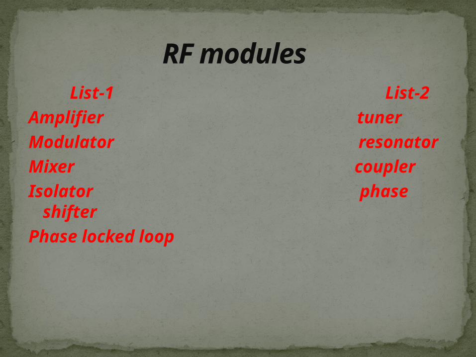
List-1 List-2
Amplifier tuner
Modulator resonator
Mixer coupler
Isolator phase shifter
Phase locked loop
RF modules
Dedicated MEMS device used for RF applications are called RF MEMS
RF MEMS technology is a high quality Three dimensionalMicroscale structure
RF MEMS
Aerospace DefensecommercialInstrumentationRF communication Microwave communicationGlobal positioning systemsBroadband wireless access and wireless data link Mobile communicationMobile robots Navigation
Applications of RF MEMS

Low power consumption High switching speedLow signal level operations Low allowable losses Low cost very high quality factor
Advantages of RF MEMS
conductor coils are called inductorsInductors are basic building blocks of all all
types of Oscillator delay and actuating circuits RF inductors are used at RF Frequency
Range Types of inductors :- straight spiral solenoid toroidal
MEMS INDUCTORS

RF micro :inductors are two types:- namely planer coil inductor solenoid type inductorplaner coil inductor:- planer inductors are either rectangular or
circular in planer inductors Q ( high quality factor ) value
can be determined with the help of this formulae Q= wLs/RsWhere Ls = inductance Rs = resistance inductor

RF antennas are of various types ,one type is solenoid structure .
Solenoid inductor can be used for tuning applications
In a receiving antenna the time variant radiated electromagnetic current appears at the surface of the solenoid structure
Solenoid inductors

A varactor is also called varicapThe short form of variable capacitor is
called varactorVaractor is an active device whose
capacitance value is varied by some meansTypes of varactors 1.semiconductor varactors 2.MEMS varactors
VARACTORS
It have long been in use not only in the RF communication systems but also in many other applications like instrumentation and control
MEMS varactors : MEMS varactor is recent developmentThe MEMS varactor coupled with an
inductor ina feedback loop sustained by negative resistance amplifier .
Semiconductor varactors
Low power consumption High quality factor Low harmonic distortion large tuning rangeTolerance for high voltage swing
Adavantages of varactors

A simple capacitor inductor circuit be act as the tuner for RF receiver
it is usually connected to the antenna When the induced RF signal in antenna matches
with this frequency resonance occurs .The method of producing resonance is known as
tuning and achieved by tuner circuitQ (high quality factor ) mathematically for tuners
Q=fr /(f +1/2 – f _1/2)
Tuner/filter

Resonators are papular where the need of high stability and selectivity arises
Resonators are used for high frequency applications at which the Lcoscillator does not have a reach
Resonator is simply occlitor ,gometrically it is a hallow chamber
The dimension of chamber plays an important role
The hallow space normally bounded by an electrically conducting surface in which oscillating electromagnetic energy is stored
RESONATOR

MEMS RESONATORS
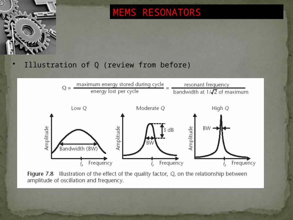
• mechanical system of a spring with spring constant k and a mass m has a resonant frequency
• In electronics, this is analogous to a series or parallel combination of capacitor and inductor, with a small series resistance (damper).
12r
kfm
MEMS RESONATORS
• Illustration of Q (review from before)
MEMS RESONATORS
• quartz crystals • IC oscillators have not been able to achieve
large Q• typical quartz crystal has a Q that reaches
10,000 or more• quality factors above 1,000 are considered high for many electronic and RF applications• frequencies of interest cover the range between 800 MHz and 2.5 GHz for front-end wireless reception and intermediate frequencies at 455 kHz and above

Patch resonator and via resonator
Micro disk resonator
Bulk mode resonator
TYPES OF RESONATORS
Resonator three dimensional high resistibility silicon substrate filled cavity resonators
fr=C
PATCH RESONATOR

MICRO DISK RESONATOR

COMB DRIVE RESONATOR
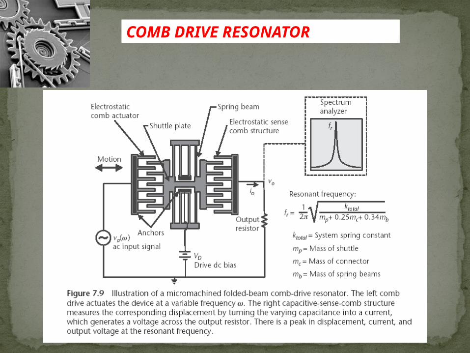
• folded springs supporting a shuttle plate
• plate oscillates back and forth in the plane of the wafer surface
• applied voltage, either positive or negative, generates an electrostatic force between the left anchor comb and shuttle comb that pulls the shuttle plate to the left
COMB DRIVE RESONATOR
Comb Drive Resonator
• A comb-drive resonator made of polycrystalline silicon
• standard surface-micromachining • beams with a thickness 2 µm, widths of 2 µm,
and lengths of 185 µm• system spring constant of 0.65 N/m
• moveable mass equal to 5.7 × 10⁻¹¹ kg• resonates at 17 kHz • same beam thickness and width but reducing
the length to 33 µm • resonates at 300 kHz
• Q can be over 50,000 in vacuum but rapidly decreases to below 50 at atmospheric pressure
• damping in air

Beam Resonator
• MEMS with higher resonant frequency
• beam resonators• University of Michigan, Ann
Arbor• reference frequency oscillators to
replace quartz crystals in cell phones
• much smaller size• ability to build several
different frequency references on a single chip
• higher resonant frequencies• ability to integrate circuitry,
either on the same chip or on a circuit chip bonded to the MEMS
• all at a lower cost than the traditional technology
Coupled Resonators as Band pass Filters
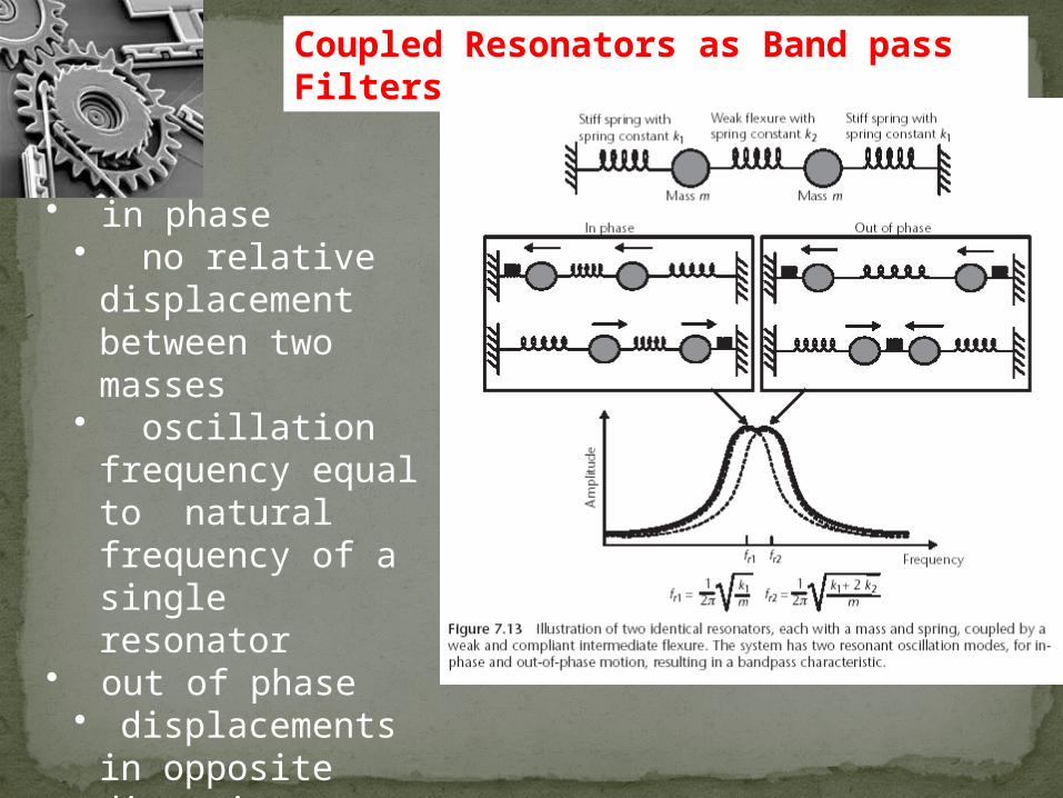
• in phase• no relative
displacement between two masses
• oscillation frequency equal to natural frequency of a single resonator
• out of phase• displacements in
opposite directions
• higher oscillation frequency
Coupled Resonators as Band pass Filters
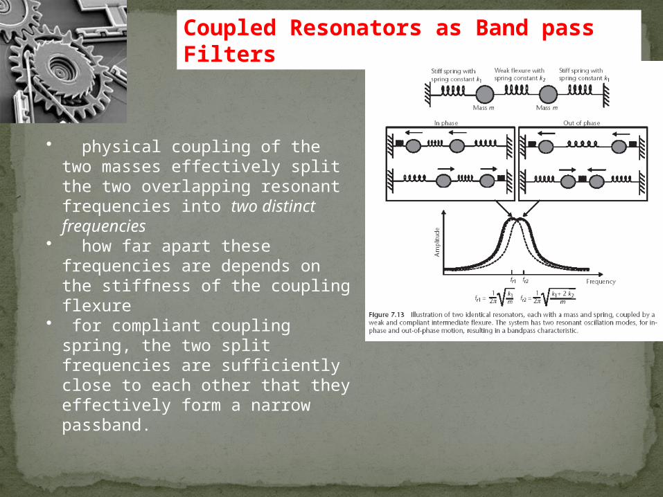
• physical coupling of the two masses effectively split the two overlapping resonant frequencies into two distinct frequencies
• how far apart these frequencies are depends on the stiffness of the coupling flexure
• for compliant coupling spring, the two split frequencies are sufficiently close to each other that they effectively form a narrow passband.
COUPLED RESONATORS AS BANDPASS FILTERS
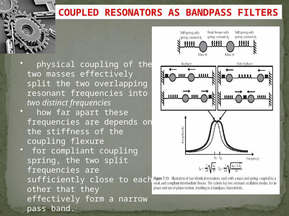
• physical coupling of the two masses effectively split the two overlapping resonant frequencies into two distinct frequencies
• how far apart these frequencies are depends on the stiffness of the coupling flexure
• for compliant coupling spring, the two split frequencies are sufficiently close to each other that they effectively form a narrow pass band.

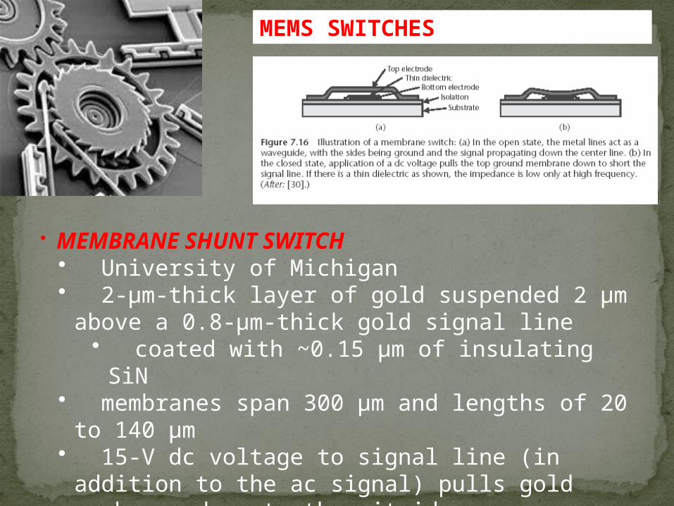
MEMS SWITCHES
• key desirable parameters in RF switches are • low insertion loss and return loss (reflection) in closed
state• high isolation in the open state• high linearity• high power-handling capability during switching• low operating voltage (for portables)• high reliability (particularly a large number of cycles
before failure)• small size• and low cost
• MEMS switches to be designed into new products, must surpass the performance of, or offer some other advantage over existing
MEMS SWITCHES
• MEMBRANE SHUNT SWITCH• University of Michigan• 2-µm-thick layer of gold suspended 2 µm above
a 0.8-µm-thick gold signal line• coated with ~0.15 µm of insulating SiN
• membranes span 300 µm and lengths of 20 to 140 µm
• 15-V dc voltage to signal line (in addition to the ac signal) pulls gold membrane down to the nitride

MEMS SWITCHES

capacitive coupled switch capacitive coupling switching is better than the contact based switching capacitive couplings are of two types 1.shunt coupling 2.series coupling

CONTACT SWITCH