Radial piston hydraulic motor with a fixed...
36
1/36 Information on available spare parts: www.boschrexroth.com/spc Radial piston hydraulic motor with a fixed displacement Types MR, MRE Nominal sizes 33 to 8200 Maximum operating pressure up to 300 bar Swept volume up to 8226 cm 3 Torques up to 32.000 Nm RE 15228/08.08 Replaces: 10.02 Overview of contents Features – Closely spaced swept volumes – Very high starting torque – High efficiency, high continuous power – Smooth rotation even at lowest speeds – High temperature shock resistance – Reversable – Highly suitable for closed loop control applications – Suitable for use with fire-resistant and bio-degradable fluids – Roller bearings for an extremely long service life – Very low operating noise – Versions with: • Sensor shaft • Incremental transducer • Brake Contents Page Ordering details 2 Section, function, symbols 3 Features, general technical data 4 Technical data 5, 6 Housing flushing 7 Pressure fluid technical data 8 Characteristic curves: Torque, power, efficiency 9 to 19 Off-load pressure 20, 21 Boost pressure 21, 22 Bearing service life 23 Unit dimensions: MR and MRE 24, 25 Unit dimensions: Shaft end 26, 27 Unit dimensions: Shaft loading 28 Holding brake: technical data, ordering details 29 Holding brake: unit dimensions 30 Shaft for speed sensing 31 Incremental transducer 32, 33 Coupling, adaptor, connection flanges 34, 35 Assembly and commissioning guidelines 36 H5619
-
Upload
truongduong -
Category
Documents
-
view
239 -
download
0
Transcript of Radial piston hydraulic motor with a fixed...
1/36
Information on available spare parts: www.boschrexroth.com/spc
Radial piston hydraulic motor with a fixed displacement
Types MR, MRE
Nominal sizes 33 to 8200Maximum operating pressure up to 300 barSwept volume up to 8226 cm3
Torques up to 32.000 Nm
RE 15228/08.08Replaces: 10.02
Overview of contents Features
– Closely spaced swept volumes– Very high starting torque– High efficiency, high continuous power– Smooth rotation even at lowest speeds– High temperature shock resistance– Reversable– Highly suitable for closed loop control applications– Suitable for use with fire-resistant and
bio-degradable fluids– Roller bearings for an extremely long service life– Very low operating noise– Versions with: •Sensorshaft •Incrementaltransducer •Brake
Contents PageOrdering details 2Section, function, symbols 3Features, general technical data 4Technical data 5, 6Housing flushing 7Pressure fluid technical data 8Characteristic curves: Torque, power, efficiency 9 to 19Off-load pressure 20, 21Boostpressure 21,22Bearingservicelife 23Unit dimensions: MR and MRE 24, 25Unit dimensions: Shaft end 26, 27Unit dimensions: Shaft loading 28Holding brake: technical data, ordering details 29Holding brake: unit dimensions 30Shaft for speed sensing 31Incremental transducer 32, 33Coupling, adaptor, connection flanges 34, 35Assembly and commissioning guidelines 36
H5619
FeaturesOrdering detailsSection, functionSymbolsMR and MRE supplementary featuresTechnical dataTechnical data Technical data Flushing of housingPressure fluid technical dataCharacteristic curves Characteristic curves Characteristic curves Characteristic curves Characteristic curves Characteristic curves Characteristic curves Characteristic curves Characteristic curves Characteristic curves Characteristic curves Characteristic curves Characteristic curves Characteristic curvesBearingservicelifeUnit dimensions: MR and MRE Unit dimensions: MR and MRE Unit dimensions: shaft variations MR and MRE Unit dimensions: shaft variations MR and MRE Shaft loadingHolding brake: technical data, ordering detailsOrdering detailsHolding brake: unit dimensions Sensor shaft for speed sensing – connections Incremental transducer - introductionUnit dimensions Incremental transducer - connection circuitTechnical dataAccessories Accessories Assembly and commissioning guidelines
2/36 Bosch Rexroth AG Hydraulics MR, MRE RE 15228/08.08
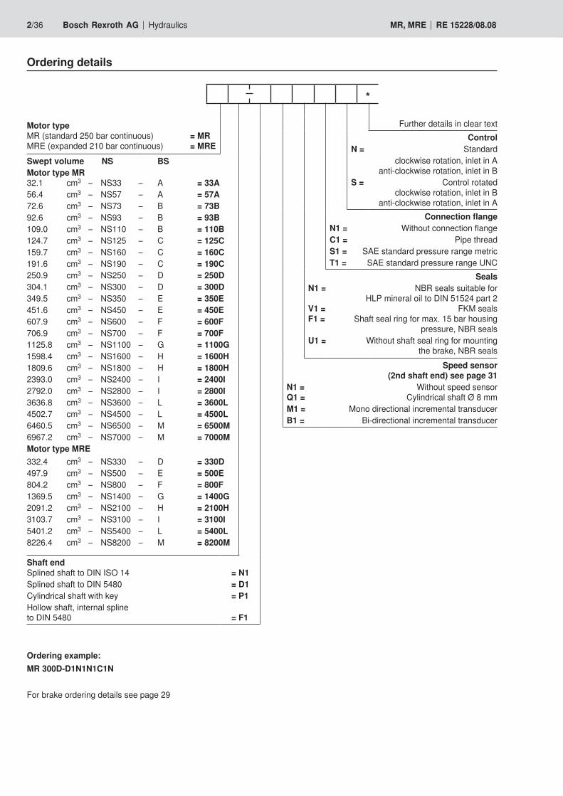
Ordering details
Motor type MR (standard 250 bar continuous) = MR MRE (expanded 210 bar continuous) = MRESwept volume NS BSMotor type MR32.1 cm3 – NS33 – A = 33A56.4 cm3 – NS57 – A = 57A72.6 cm3 – NS73 – B = 73B92.6 cm3 – NS93 – B = 93B109.0 cm3 – NS110 – B = 110B124.7 cm3 – NS125 – C = 125C159.7 cm3 – NS160 – C = 160C191.6 cm3 – NS190 – C = 190C250.9 cm3 – NS250 – D = 250D304.1 cm3 – NS300 – D = 300D349.5 cm3 – NS350 – E = 350E451.6 cm3 – NS450 – E = 450E607.9 cm3 – NS600 – F = 600F706.9 cm3 – NS700 – F = 700F1125.8 cm3 – NS1100 – G = 1100G1598.4 cm3 – NS1600 – H = 1600H1809.6 cm3 – NS1800 – H = 1800H2393.0 cm3 – NS2400 – I = 2400I2792.0 cm3 – NS2800 – I = 2800I3636.8 cm3 – NS3600 – L = 3600L4502.7 cm3 – NS4500 – L = 4500L6460.5 cm3 – NS6500 – M = 6500M6967.2 cm3 – NS7000 – M = 7000MMotor type MRE332.4 cm3 – NS330 – D = 330D497.9 cm3 – NS500 – E = 500E804.2 cm3 – NS800 – F = 800F1369.5 cm3 – NS1400 – G = 1400G2091.2 cm3 – NS2100 – H = 2100H3103.7 cm3 – NS3100 – I = 3100I5401.2 cm3 – NS5400 – L = 5400L8226.4 cm3 – NS8200 – M = 8200M
Shaft end Splined shaft to DIN ISO 14 = N1 Splined shaft to DIN 5480 = D1Cylindrical shaft with key = P1Hollow shaft, internal spline to DIN 5480 = F1
Further details in clear textControl
N = Standardclockwise rotation, inlet in A
anti-clockwiserotation,inletinBS = Control rotated
clockwiserotation,inletinB anti-clockwise rotation, inlet in A
Connection flange N1 = Without connection flange C1 = Pipe threadS1 = SAE standard pressure range metricT1 = SAE standard pressure range UNC
SealsN1 = NBRsealssuitablefor
HLP mineral oil to DIN 51524 part 2 V1 = FKM seals F1 = Shaft seal ring for max. 15 bar housing
pressure,NBRsealsU1 = Without shaft seal ring for mounting
thebrake,NBRsealsSpeed sensor
(2nd shaft end) see page 31 N1 = Without speed sensor Q1 = Cylindrical shaft Ø 8 mmM1 = Mono directional incremental transducerB1 = Bi-directionalincrementaltransducer
*
Ordering example:MR 300D-D1N1N1C1N
For brake ordering details see page 29
Hydraulics Bosch Rexroth AGRE 15228/08.08 MR, MRE 3/36
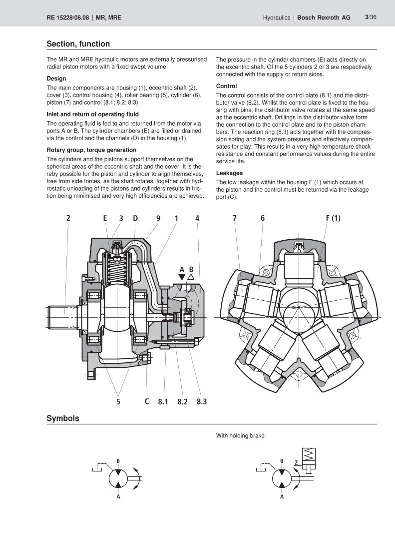
Section, function
The MR and MRE hydraulic motors are externally pressurised radial piston motors with a fixed swept volume.
DesignThe main components are housing (1), eccentric shaft (2), cover (3), control housing (4), roller bearing (5), cylinder (6), piston (7) and control (8.1; 8.2; 8.3).
Inlet and return of operating fluidThe operating fluid is fed to and returned from the motor via portsAorB.Thecylinderchambers(E)arefilledordrainedvia the control and the channels (D) in the housing (1).
Rotary group, torque generationThe cylinders and the pistons support themselves on the spherical areas of the eccentric shaft and the cover. It is the-reby possible for the piston and cylinder to align themselves, free from side forces, as the shaft rotates, together with hyd-rostatic unloading of the pistons and cylinders results in fric-tion being minimised and very high efficiencies are achieved.
A B
2 E 3 D 9 1 4 7 6 F (1)
8.38.28.1C5
Symbols
B
A
B
A
Z
With holding brake
The pressure in the cylinder chambers (E) acts directly on the excentric shaft. Of the 5 cylinders 2 or 3 are respectively connected with the supply or return sides.
ControlThe control consists of the control plate (8.1) and the distri-butor valve (8.2). Whilst the control plate is fixed to the hou-sing with pins, the distributor valve rotates at the same speed as the eccentric shaft. Drillings in the distributor valve form the connection to the control plate and to the piston cham-bers. The reaction ring (8.3) acts together with the compres-sion spring and the system pressure and effectively compen-sates for play. This results in a very high temperature shock resistance and constant performance values during the entire service life.
LeakagesThe low leakage within the housing F (1) which occurs at the piston and the control must be returned via the leakage port (C).
4/36 Bosch Rexroth AG Hydraulics MR, MRE RE 15228/08.08
General – MR; MREModel Radial piston motor, externally pressurised, constant
Type MR; MRE
Mounting style Flange mounting
Connection type Connection flange
Installation Optional (take the installation guidelines on page 36 into account)
Bearingservicelife,shaftloadability See pages 23 and 28
Direction of rotation Clockwise/anti-clockwise - reversible
Pressure fluid HLPmineraloiltoDIN51524part2;HFBandHFC as well as bio-degradable fluids on request; with phosphate ester (HFD), FKM seals are necessary
Pressure fluid temperature range °C –30 to +80
Viscosity range mm2/s 18 to 1000, recommended operating range 30 to 50 in motor housing, must be adhered to with high constant powers
Cleanliness class to ISO codes Maximum permissible pressure fluid degree of contamination is to ISO 4406 class19/16/13
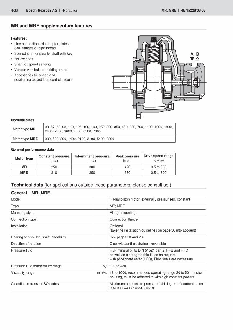
MR and MRE supplementary features
Features:• Lineconnectionsviaadaptorplates,
SAE flanges or pipe thread• Splinedshaftorparallelshaftwithkey• Hollowshaft• Shaftforspeedsensing• Versionwithbuilt-onholdingbrake• Accessoriesforspeedand
positioning closed loop control circuits
Nominal sizes
Motor type MR 33, 57, 73, 93, 110, 125, 160, 190, 250, 300, 350, 450, 600, 700, 1100, 1600, 1800, 2400, 2800, 3600, 4500, 6500, 7000
Motor type MRE 330, 500, 800, 1400, 2100, 3100, 5400, 8200
Motor type Constant pressure in bar
Intermittent pressure in bar
Peak pressure in bar
Drive speed rangein min-1
MR 250 300 420 0.5 to 800MRE 210 250 350 0.5 to 600
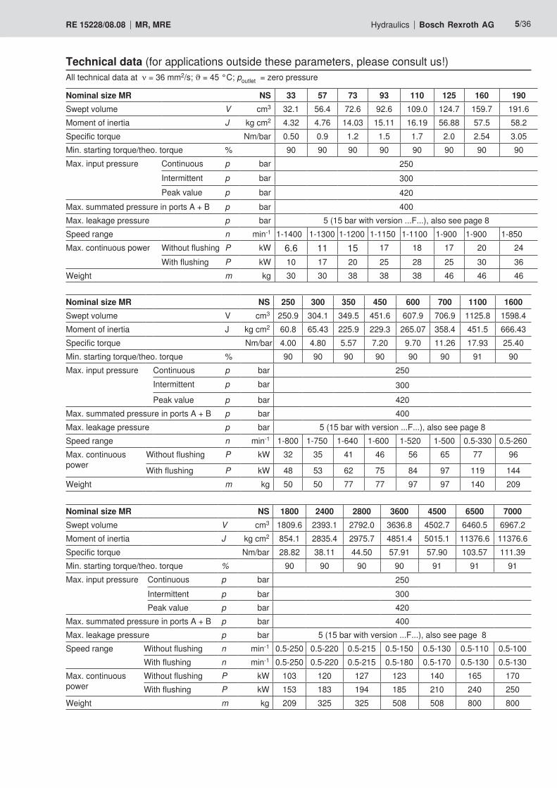
Technical data (for applications outside these parameters, please consult us!)
A B
General performance data
Hydraulics Bosch Rexroth AGRE 15228/08.08 MR, MRE 5/36
Technical data (for applications outside these parameters, please consult us!)
Nominal size MR NS 250 300 350 450 600 700 1100 1600Swept volume V cm3 250.9 304.1 349.5 451.6 607.9 706.9 1125.8 1598.4Moment of inertia J kg cm2 60.8 65.43 225.9 229.3 265.07 358.4 451.5 666.43Specific torque Nm/bar 4.00 4.80 5.57 7.20 9.70 11.26 17.93 25.40Min. starting torque/theo. torque % 90 90 90 90 90 90 91 90Max. input pressure Continuous p bar 250
Intermittent p bar 300Peak value p bar 420
Max.summatedpressureinportsA+B p bar 400Max. leakage pressure p bar 5 (15 bar with version ...F...), also see page 8Speed range n min-1 1-800 1-750 1-640 1-600 1-520 1-500 0.5-330 0.5-260Max. continuous power
Without flushing P kW 32 35 41 46 56 65 77 96
With flushing P kW 48 53 62 75 84 97 119 144Weight m kg 50 50 77 77 97 97 140 209
All technical data at ν = 36 mm2/s; ϑ = 45 °C; poutlet = zero pressure
Nominal size MR NS 33 57 73 93 110 125 160 190Swept volume V cm3 32.1 56.4 72.6 92.6 109.0 124.7 159.7 191.6Moment of inertia J kg cm2 4.32 4.76 14.03 15.11 16.19 56.88 57.5 58.2Specific torque Nm/bar 0.50 0.9 1.2 1.5 1.7 2.0 2.54 3.05Min. starting torque/theo. torque % 90 90 90 90 90 90 90 90Max. input pressure Continuous p bar 250
Intermittent p bar 300Peak value p bar 420
Max.summatedpressureinportsA+B p bar 400Max. leakage pressure p bar 5 (15 bar with version ...F...), also see page 8Speed range n min-1 1-1400 1-1300 1-1200 1-1150 1-1100 1-900 1-900 1-850Max. continuous power Without flushing P kW 6.6 11 15 17 18 17 20 24
With flushing P kW 10 17 20 25 28 25 30 36Weight m kg 30 30 38 38 38 46 46 46
Nominal size MR NS 1800 2400 2800 3600 4500 6500 7000Swept volume V cm3 1809.6 2393.1 2792.0 3636.8 4502.7 6460.5 6967.2Moment of inertia J kg cm2 854.1 2835.4 2975.7 4851.4 5015.1 11376.6 11376.6Specific torque Nm/bar 28.82 38.11 44.50 57.91 57.90 103.57 111.39Min. starting torque/theo. torque % 90 90 90 90 91 91 91Max. input pressure Continuous p bar 250
Intermittent p bar 300Peak value p bar 420
Max.summatedpressureinportsA+B p bar 400Max. leakage pressure p bar 5 (15 bar with version ...F...), also see page 8Speed range Without flushing n min-1 0.5-250 0.5-220 0.5-215 0.5-150 0.5-130 0.5-110 0.5-100
With flushing n min-1 0.5-250 0.5-220 0.5-215 0.5-180 0.5-170 0.5-130 0.5-130Max. continuous power
Without flushing P kW 103 120 127 123 140 165 170With flushing P kW 153 183 194 185 210 240 250
Weight m kg 209 325 325 508 508 800 800
6/36 Bosch Rexroth AG Hydraulics MR, MRE RE 15228/08.08
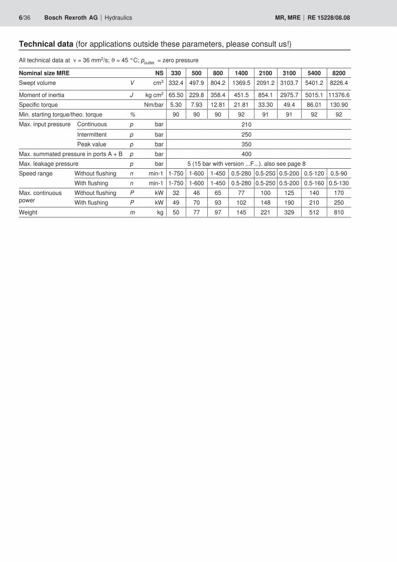
Technical data (for applications outside these parameters, please consult us!)
All technical data at ν = 36 mm2/s; ϑ = 45 °C; poutlet = zero pressure
Nominal size MRE NS 330 500 800 1400 2100 3100 5400 8200Swept volume V cm3 332.4 497.9 804.2 1369.5 2091.2 3103.7 5401.2 8226.4
Moment of inertia J kg cm2 65.50 229.8 358.4 451.5 854.1 2975.7 5015.1 11376.6Specific torque Nm/bar 5.30 7.93 12.81 21.81 33.30 49.4 86.01 130.90Min. starting torque/theo. torque % 90 90 90 92 91 91 92 92Max. input pressure Continuous p bar 210
Intermittent p bar 250Peak value p bar 350
Max.summatedpressureinportsA+B p bar 400Max. leakage pressure p bar 5 (15 bar with version ...F...). also see page 8Speed range Without flushing n min-1 1-750 1-600 1-450 0.5-280 0.5-250 0.5-200 0.5-120 0.5-90
With flushing n min-1 1-750 1-600 1-450 0.5-280 0.5-250 0.5-200 0.5-160 0.5-130Max. continuous power
Without flushing P kW 32 46 65 77 100 125 140 170With flushing P kW 49 70 93 102 148 190 210 250
Weight m kg 50 77 97 145 221 329 512 810
Hydraulics Bosch Rexroth AGRE 15228/08.08 MR, MRE 7/36
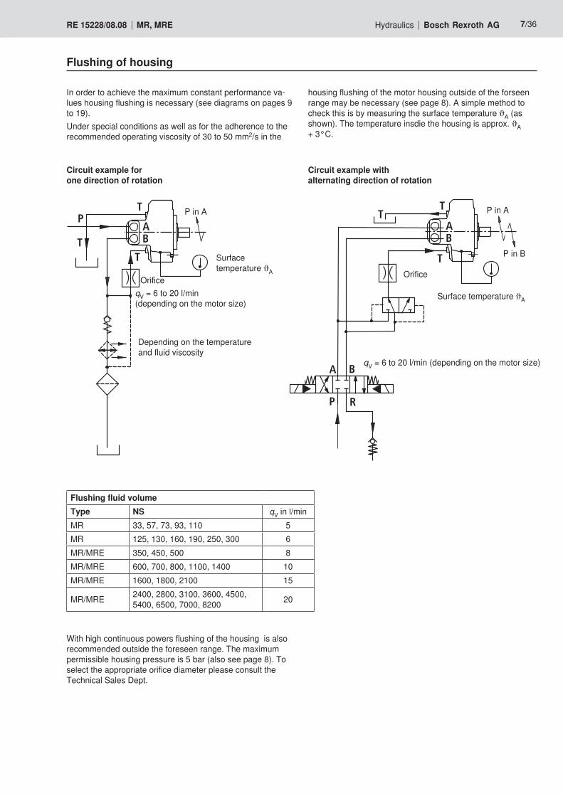
Flushing of housing
In order to achieve the maximum constant performance va-lues housing flushing is necessary (see diagrams on pages 9 to 19). Under special conditions as well as for the adherence to the recommended operating viscosity of 30 to 50 mm2/s in the
housing flushing of the motor housing outside of the forseen range may be necessary (see page 8). A simple method to check this is by measuring the surface temperature ϑA (as shown). The temperature insdie the housing is approx. ϑA + 3°C.
Circuit example for one direction of rotation
Circuit example with alternating direction of rotation
Flushing fluid volumeType NS qV in l/minMR 33, 57, 73, 93, 110 5MR 125, 130, 160, 190, 250, 300 6MR/MRE 350, 450, 500 8MR/MRE 600, 700, 800, 1100, 1400 10MR/MRE 1600, 1800, 2100 15
MR/MRE 2400, 2800, 3100, 3600, 4500, 5400, 6500, 7000, 8200 20
With high continuous powers flushing of the housing is also recommended outside the foreseen range. The maximum permissible housing pressure is 5 bar (also see page 8). To select the appropriate orifice diameter please consult the Technical Sales Dept.
AB
TT
T
AB
T
T
P
T
A B
P R
Orifice
qV = 6 to 20 l/min (depending on the motor size)
Surface temperature ϑA
Surface temperature ϑA
qV = 6 to 20 l/min (depending on the motor size)
Depending on the temperature and fluid viscosity
Orifice
P in A P in A
PinB
8/36 Bosch Rexroth AG Hydraulics MR, MRE RE 15228/08.08
Pressure fluid technical dataPressure fluidSee catalogue sheet RE 07075 for detailed information regar-ding the selection of pressure fluids before carrying out any engineering/design work. Further notes on installation and commissioning can be found on page 36 of this catalogue sheet. When operating with HF pressure fluids or bio-degradable pressure fluids possible limitations to the technical data must be taken into consideration, please consult ourselves.
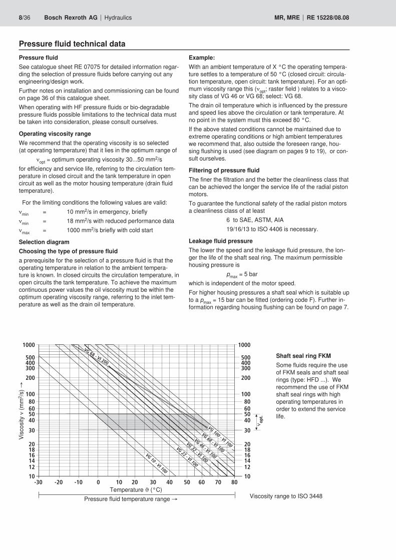
Operating viscosity rangeWe recommend that the operating viscosity is so selected (at operating temperature) that it lies in the optimum range of
νopt = optimum operating viscosity 30...50 mm2/sfor efficiency and service life, referring to the circulation tem-perature in closed circuit and the tank temperature in open circuit as well as the motor housing temperature (drain fluid temperature).
For the limiting conditions the following values are valid:νmin = 10 mm2/s in emergency, brieflyνmin = 18 mm2/s with reduced performance dataνmax = 1000 mm2/s briefly with cold start
Selection diagramChoosing the type of pressure fluida prerequisite for the selection of a pressure fluid is that the operating temperature in relation to the ambient tempera-ture is known. In closed circuits the circulation temperature, in open circuits the tank temperature. To achieve the maximum continuous power values the oil viscosity must be within the optimum operating viscosity range, referring to the inlet tem-perature as well as the drain oil temperature.
Shaft seal ring FKMSome fluids require the use of FKM seals and shaft seal rings (type: HFD ...). We recommend the use of FKM shaft seal rings with high operating temperatures in order to extend the service life.
VG 46 - VI 100
VG 68 - VI 100VG 10 - VI 100
VG 22 - VI 100
VG 32 - VI 100
VG 100 - VI 100
VG 68 - VI 200
-30 -20 -10 0 10 20 30 40 50 60 70 8010
1214161820
30
40506080
100
200
300400500
1000
10
1214161820
30
40506080
100
200
300400500
1000
Temperature ϑ (°C)Pressure fluid temperature range →
Visc
osity
ν (m
m2 /s
) →
ν opt.
Viscosity range to ISO 3448
Example: With an ambient temperature of X °C the operating tempera-ture settles to a temperature of 50 °C (closed circuit: circula-tion temperature, open circuit: tank temperature). For an opti-mum viscosity range this (νopt; raster field ) relates to a visco-sity class of VG 46 or VG 68; select: VG 68.The drain oil temperature which is influenced by the pressure and speed lies above the circulation or tank temperature. At no point in the system must this exceed 80 °C.If the above stated conditions cannot be maintained due to extreme operating conditions or high ambient temperatures we recommend that, also outside the foreseen range, hou-sing flushing is used (see diagram on pages 9 to 19), or con-sult ourselves.
Filtering of pressure fluidThe finer the filtration and the better the cleanliness class that can be achieved the longer the service life of the radial piston motors.To guarantee the functional safety of the radial piston motors a cleanliness class of at least 6 to SAE, ASTM, AIA 19/16/13 to ISO 4406 is necessary.
Leakage fluid pressureThe lower the speed and the leakage fluid pressure, the lon-ger the life of the shaft seal ring. The maximum permissible housing pressure is pmax = 5 barwhich is independent of the motor speed.For higher housing pressures a shaft seal which is suitable up to a pmax = 15 bar can be fitted (ordering code F). Further in-formation regarding housing flushing can be found on page 7.
Hydraulics Bosch Rexroth AGRE 15228/08.08 MR, MRE 9/36
60
30
90
120
150
180
210
200 400 600 800 1000 1200 1300
���
η
�����η
��� ���
���
���
�����
���
96%
8 l/min 16 l/min 39 l/min32 l/min24 l/min 47 l/min 55 l/min 71 l/min63 l/min
100 bar
150 bar
200 bar
300 bar
250 bar
3 Kw
7 Kw
5 Kw
15 Kw
11 Kw
9 Kw
13 Kw17 Kw
5
4
3
2
1
�����
27 l/min13 l/min1 l/min 4 l/min 9 l/min 18 l/min 22 l/min 40 l/min31 l/min 36 l/min 45 l/min
10Kw
�����
���
���
100 bar
150 bar
���
���
250 bar
200 bar
300 bar
5Kw
3Kw
4Kw
8Kw
7Kw
9Kw
6.6Kw
���
���
30
15
140 280 420 560 700 980840 1120 14001260
90
105
75
60
45
120
η
5
η3
4
2
1
��� ���
η �����
��� ���
�����
η
���
���
46 l/min9 l/min3 l/min 18 l/min 27 l/min 37 l/min 55 l/min 64 l/min 82 l/min73 l/min
600200 400
240
160
80
800 1000 1150
400
320
100 bar
150 bar
200 bar
250 bar
20 Kw
17 Kw18 Kw
15 Kw
13 Kw
8 Kw
10 Kw
6 Kw
300 bar
5
4
3
2
1
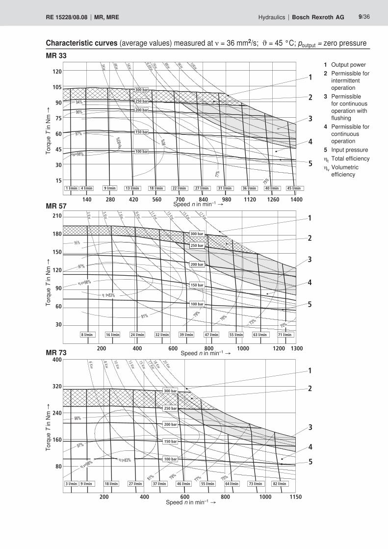
Characteristic curves (average values) measured at ν = 36 mm2/s; ϑ = 45 °C; poutput = zero pressureTo
rque
T in
Nm
→To
rque
T in
Nm
→MR 33
MR 57
MR 73
Speed n in min–1 →
Speed n in min–1 →
Speed n in min–1 →
Torq
ue T
in N
m →
1 Output power2 Permissible for
intermittent operation
3 Permissible for continuous operation with flushing
4 Permissible for continuous operation
5 Input pressureηt Total efficiencyηv Volumetric
efficiency
10/36 Bosch Rexroth AG Hydraulics MR, MRE RE 15228/08.08
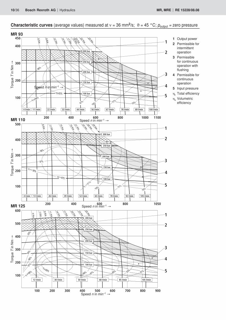
Characteristic curves (average values) measured at ν = 36 mm2/s; ϑ = 45 °C; poutput = zero pressure
Torq
ue T
in N
m →
Torq
ue T
in N
m →
MR 93
MR 110
MR 125
η
η
22 l/min4 l/min 11 l/min 33 l/min 44 l/min 67 l/min56 l/min 78 l/min 100 l/min89 l/min
200
200
100
300
400
450
400 600 800 11001000
100 bar
150 bar
200 bar
250 bar
300 bar
5
4
3
2
1
η
η t = 81%
η
52 l/min4 l/min
100
200
26 l/min
200
13 l/min
400
39 l/min
300
400
500
600
65 l/min
800
78 l/min 92 l/min
1050
105 l/min
200 bar
100 bar
150 bar
300 bar
250 bar
4
5
3
1
2
η
η
68 l/min12 l/min 30 l/min 50 l/min 105 l/min85 l/min
100
100 200 400300 500
200
300
400
500
600
800600 700 900
250 bar
100 bar
150 bar
200 bar
300 bar
5
2
3
4
1
Torq
ue T
in N
m →
Speed n in min–1 →
Speed n in min–1 →
Speed n in min–1 →
Speed n in min–1 →
1 Output power2 Permissible for
intermittent operation
3 Permissible for continuous operation with flushing
4 Permissible for continuous operation
5 Input pressureηt Total efficiencyηv Volumetric
efficiency
Hydraulics Bosch Rexroth AGRE 15228/08.08 MR, MRE 11/36
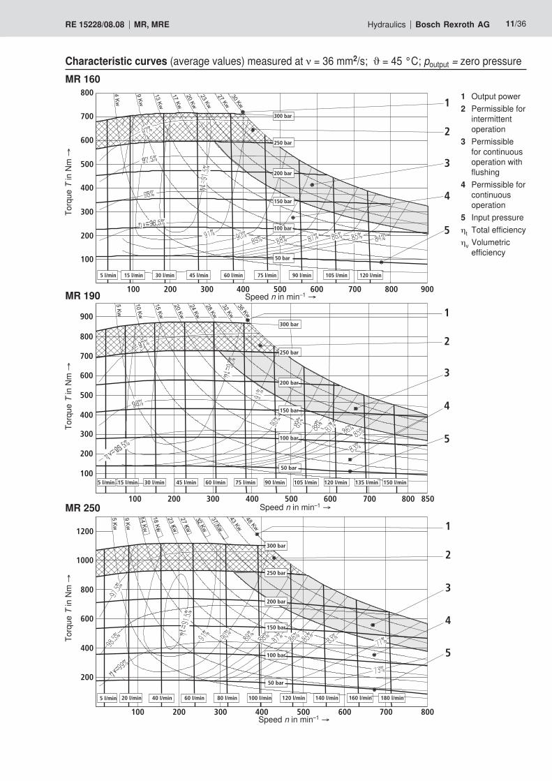
Characteristic curves (average values) measured at ν = 36 mm2/s; ϑ = 45 °C; poutput = zero pressureMR 160
Torq
ue T
in N
m →
Torq
ue T
in N
m →
MR 190
MR 250
Torq
ue T
in N
m →
300 bar
250 bar
200 bar
150 bar
100 bar
50 bar
300 bar
250 bar
200 bar
150 bar
100 bar
5 l/min 15 l/min 30 l/min 45 l/min 60 l/min 75 l/min 90 l/min 120 l/min105 l/min
100 200 300 400 500 600 700 800
800
700
600
500
400
300
200
100
900
5
4
3
2
1
50 bar
5
4
3
2
1
5 l/min 15 l/min 30 l/min 45 l/min 60 l/min 75 l/min 90 l/min 120 l/min105 l/min 135 l/min 150 l/min
100 200 300 400 500 600 700 800
900
800
700
600
500
400
300
200
100
850
5 l/min 20 l/min 40 l/min 60 l/min 80 l/min 100 l/min
300 bar
200 bar
150 bar
100 bar
50 bar
1200
1000
800
600
400
200
120 l/min 180 l/min160 l/min140 l/min
100 200 300 400 500 600 700
5
4
3
2
1
800
250 bar
Speed n in min–1 →
Speed n in min–1 →
Speed n in min–1 →
1 Output power2 Permissible for
intermittent operation
3 Permissible for continuous operation with flushing
4 Permissible for continuous operation
5 Input pressureηt Total efficiencyηv Volumetric
efficiency
12/36 Bosch Rexroth AG Hydraulics MR, MRE RE 15228/08.08
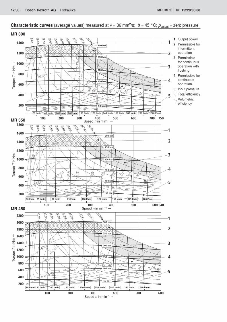
Characteristic curves (average values) measured at ν = 36 mm2/s; ϑ = 45 °C; poutput = zero pressure
MR 300
Torq
ue TinNm→
Torq
ue TinNm→
MR 350
MR 450
Torq
ue TinNm→
40 l/min 60 l/min 80 l/min20 l/min 100 l/min 120 l/min 140 l/min 160 l/min 180 l/min 200 l/min 220 l/min
5
4
3
2
1300 bar
250 bar
200 bar
150 bar
100 bar
50 bar
100 200 300 400 500 600 700 750
1400
1200
1000
800
600
400
200
10 l/min 25 l/min 50 l/min 75 l/min 100 l/min 125 l/min 150 l/min 175 l/min 200 l/min
5
4
3
2
1300 bar
250 bar
200 bar
150 bar
100 bar
50 bar
100 200 300 400 500 600
200
400
600
800
1000
1200
1400
1600
1800
640
60 l/min 90 l/min10 l/min 30 l/min 150 l/min 240 l/min210 l/min180 l/min120 l/min
5
4
3
2
1300 bar
250 bar
200 bar
150 bar
100 bar
50 bar
2200
2000
1800
1600
1400
1200
1000
800
600
400
200
100 200 300 400 500 600
Speed n in min–1→
Speed n in min–1→
Speed n in min–1→
1 Output power2 Permissible for
intermittent operation
3 Permissible for continuous operation with flushing
4 Permissible for continuous operation
5 Input pressureηt Total efficiencyηv Volumetric
efficiency
Hydraulics Bosch Rexroth AGRE 15228/08.08 MR, MRE 13/36
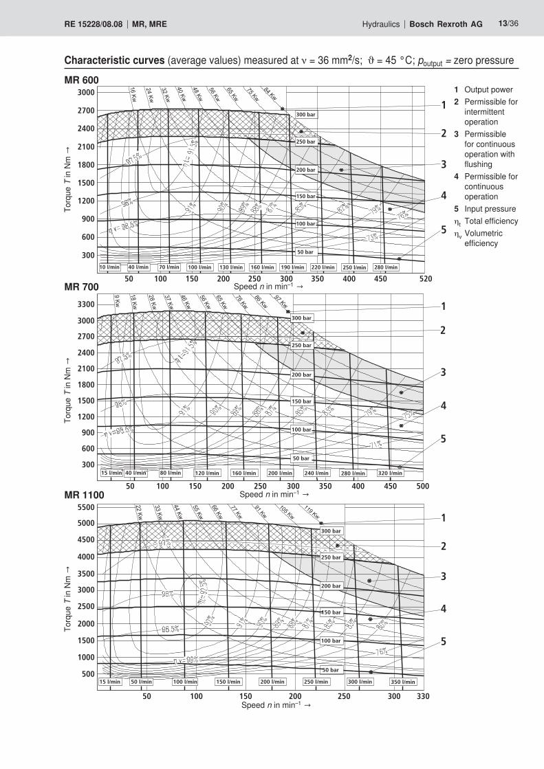
Characteristic curves (average values) measured at ν = 36 mm2/s; ϑ = 45 °C; poutput = zero pressure
MR 600To
rque
TinNm→
Torq
ue TinNm→
MR 700
MR 1100
Torq
ue TinNm→
50 100 150 200 250 300 350 400 450
5
4
3
2
1300 bar
250 bar
150 bar
100 bar
50 bar
200 bar
3000
2700
2400
2100
1800
1500
1200
600
300
900
160 l/min100 l/min 130 l/min 190 l/min 220 l/min 250 l/min 280 l/min10 l/min 40 l/min 70 l/min
520
300 bar
250 bar
150 bar
100 bar
50 bar
200 bar
50 100 150 200 250 300 350 400 450 500
3000
2700
2400
2100
1800
1500
1200
900
600
300
3300
5
4
3
2
1
240 l/min120 l/min 160 l/min 200 l/min 280 l/min 320 l/min15 l/min 40 l/min 80 l/min
5
4
3
2
1300 bar
150 bar
100 bar
50 bar500
1000
1500
2000
2500
3000
3500
4000
4500
5000
5500
50 100 150 200 250 300 330
200 bar
250 bar
300 l/min100 l/min 150 l/min 200 l/min 250 l/min 350 l/min50 l/min15 l/min
Speed n in min–1→
Speed n in min–1→
Speed n in min–1→
1 Output power2 Permissible for
intermittent operation
3 Permissible for continuous operation with flushing
4 Permissible for continuous operation
5 Input pressureηt Total efficiencyηv Volumetric
efficiency
14/36 Bosch Rexroth AG Hydraulics MR, MRE RE 15228/08.08
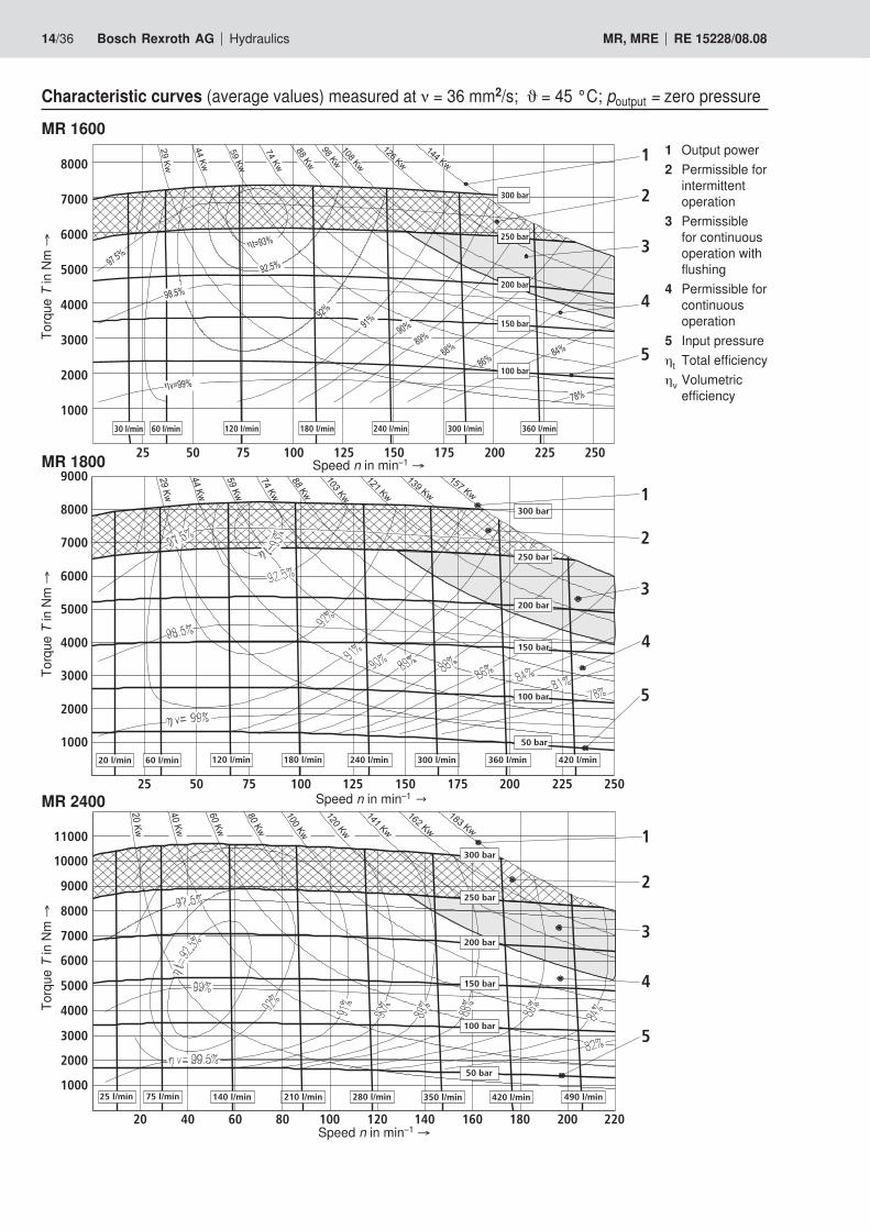
Characteristic curves (average values) measured at ν = 36 mm2/s; ϑ = 45 °C; poutput = zero pressure
MR 1600
Torq
ue T
in N
m →
Torq
ue T
in N
m →
MR 1800
MR 2400
Torq
ue T
in N
m →
240 l/min 420 l/min360 l/min
25 50 75 100 125 150 175 200 225 250
1000
9000
8000
7000
6000
5000
4000
3000
20005
4
3
2
1300 bar
250 bar
200 bar
150 bar
100 bar
50 bar
120 l/min 180 l/min 300 l/min20 l/min 60 l/min
25 l/min 75 l/min
20 40 60 80 100 120 140 160 180 200 220
11000
10000
9000
8000
7000
6000
5000
4000
3000
2000
1000
5
4
3
2
1300 bar
250 bar
200 bar
150 bar
100 bar
50 bar
420 l/min140 l/min 210 l/min 280 l/min 350 l/min 490 l/min
η
η
7525 50 100 125
1000
2000
3000
4000
175150 200 225 250
7000
5000
6000
8000
240 l/min30 l/min 120 l/min60 l/min 180 l/min
100 bar
300 l/min 360 l/min
200 bar
150 bar
5
4
300 bar
250 bar3
2
1
Speed n in min–1 →
Speed n in min–1 →
Speed n in min–1 →
1 Output power2 Permissible for
intermittent operation
3 Permissible for continuous operation with flushing
4 Permissible for continuous operation
5 Input pressureηt Total efficiencyηv Volumetric
efficiency
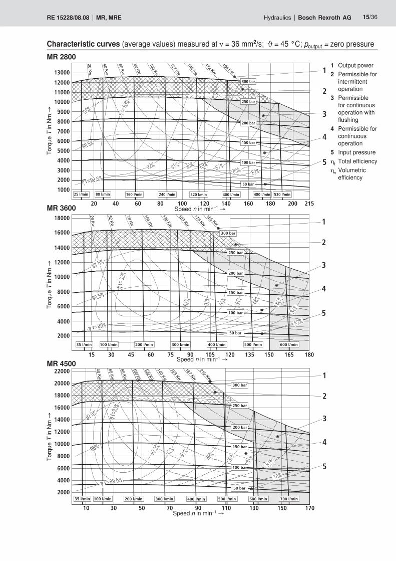
Hydraulics Bosch Rexroth AGRE 15228/08.08 MR, MRE 15/36
Characteristic curves (average values) measured at ν = 36 mm2/s; ϑ = 45 °C; poutput = zero pressureMR 2800
Torq
ue T
in N
m →
Torq
ue T
in N
m →
MR 3600
MR 4500
Torq
ue T
in N
m →
1000
2000
3000
4000
5000
6000
7000
8000
9000
10000
11000
12000
13000
20 40 60 80 100 120 140 160 180 200 215
1
2
3
4
5
2000
4000
6000
8000
10000
12000
14000
16000
18000
20000
22000
10 30 50 70 90 110 130 150 170
1
2
3
4
5
300 bar
250 bar
200 bar
150 bar
100 bar
50 bar
5
4
3
2
1
25 l/min 80 l/min 160 l/min 240 l/min 320 l/min 400 l/min 480 l/min 530 l/min
300 l/min 400 l/min 500 l/min 600 l/min
15 30 45 60 75 90 105 120 135 150 165 180
250 bar
200 bar
150 bar
100 bar
50 bar
35 l/min 200 l/min100 l/min
300 bar
2000
4000
6000
8000
10000
12000
14000
16000
18000
300 bar
250 bar
200 bar
150 bar
100 bar
50 bar
300 l/min200 l/min 400 l/min 500 l/min 600 l/min 700 l/min35 l/min 100 l/min
Speed n in min–1 →
Speed n in min–1 →
Speed n in min–1 →
1 Output power2 Permissible for
intermittent operation
3 Permissible for continuous operation with flushing
4 Permissible for continuous operation
5 Input pressureηt Total efficiencyηv Volumetric
efficiency
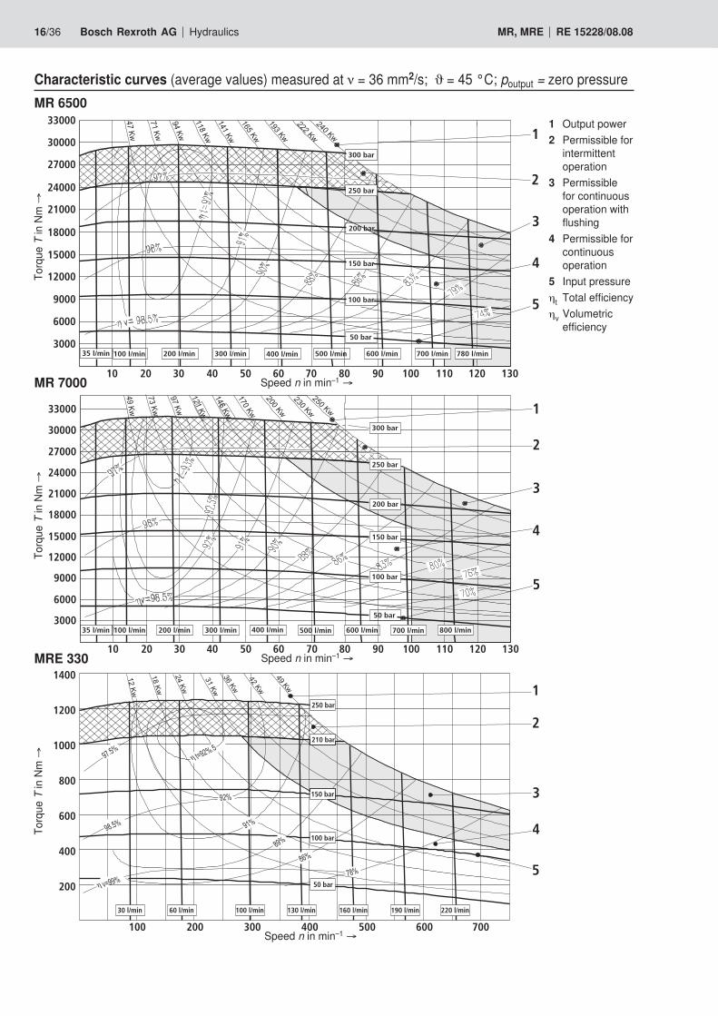
16/36 Bosch Rexroth AG Hydraulics MR, MRE RE 15228/08.08
Characteristic curves (average values) measured at ν = 36 mm2/s; ϑ = 45 °C; poutput = zero pressureMR 6500
Torq
ue T
in N
m →
Torq
ue T
in N
m →
MR 7000
MRE 330
Torq
ue T
in N
m →
3000
6000
9000
12000
15000
18000
21000
24000
27000
30000
33000
10 20 30 40 50 60 70 80 90 100 110 120 130
300 bar
250 bar
200 bar
150 bar
100 bar
50 bar
100 l/min35 l/min 300 l/min200 l/min 400 l/min 500 l/min 600 l/min 780 l/min700 l/min
1
2
3
4
5
300 bar
200 bar
150 bar
100 bar
50 bar
800 l/min35 l/min 100 l/min 200 l/min 300 l/min 400 l/min 500 l/min 700 l/min600 l/min
10 20 30 40 50 60 70 80 90 100 110 120 130
33000
30000
27000
24000
21000
18000
15000
12000
9000
6000
3000
250 bar
1
2
3
4
5
3
5
4
2
1
Speed n in min–1 →
Speed n in min–1 →
Speed n in min–1 →
1 Output power2 Permissible for
intermittent operation
3 Permissible for continuous operation with flushing
4 Permissible for continuous operation
5 Input pressureηt Total efficiencyηv Volumetric
efficiency
Hydraulics Bosch Rexroth AGRE 15228/08.08 MR, MRE 17/36
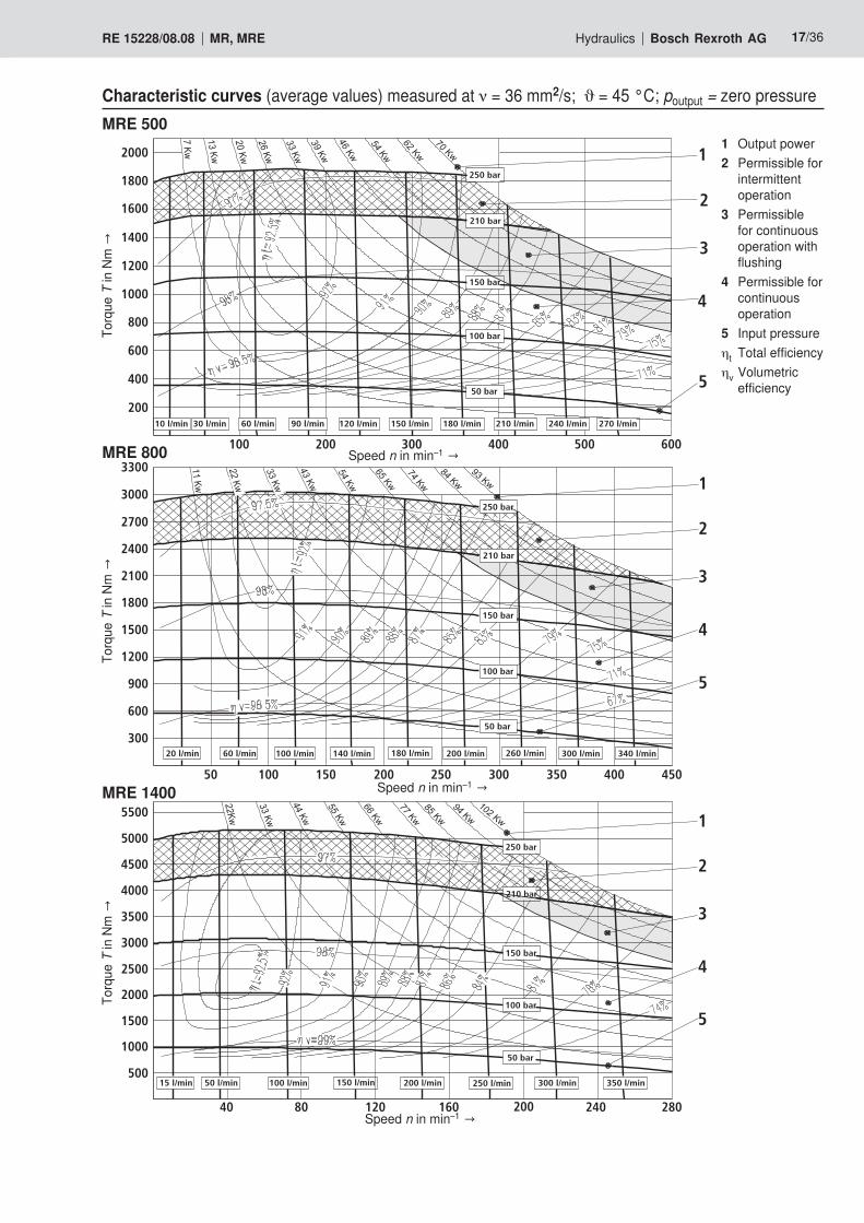
Characteristic curves (average values) measured at ν = 36 mm2/s; ϑ = 45 °C; poutput = zero pressureMRE 500
Torq
ue TinNm→
MRE 800
MRE 1400
Torq
ue TinNm→
250 bar
180 l/min 210 l/min 240 l/min 270 l/min60 l/min 150 l/min120 l/min
210 bar
150 bar
100 bar
50 bar
30 l/min10 l/min 90 l/min
100 200 300 400 500 600
2000
1800
1600
1400
1200
1000
800
600
400
200
1
2
3
4
5
60 l/min20 l/min 100 l/min 200 l/min140 l/min 180 l/min 340 l/min300 l/min260 l/min
50 100 150 200 250 300 350 400 450
300
600
900
1200
1500
1800
2100
2400
2700
3000
3300
250 bar
210 bar
150 bar
100 bar
50 bar
1
2
3
4
5
50 l/min15 l/min 100 l/min 200 l/min 300 l/min150 l/min 250 l/min 350 l/min
210 bar
150 bar
100 bar
250 bar
50 bar
1
2
3
4
5
40 80 120 160 200 240 280
500
1000
1500
2000
2500
3000
3500
4000
4500
5000
5500
Speed n in min–1→
Torq
ue TinNm→
Speed n in min–1→
Speed n in min–1→
1 Output power2 Permissible for
intermittent operation
3 Permissible for continuous operation with flushing
4 Permissible for continuous operation
5 Input pressureηt Total efficiencyηv Volumetric
efficiency
18/36 Bosch Rexroth AG Hydraulics MR, MRE RE 15228/08.08
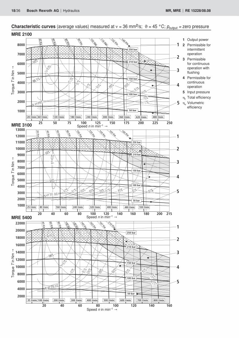
Characteristic curves (average values) measured at ν = 36 mm2/s; ϑ = 45 °C; poutput = zero pressureMRE 2100
Torq
ue TinNm→
MRE 3100
MRE 5400
Torq
ue TinNm→
1
2
3
4
5
20 l/min 60 l/min 120 l/min 240 l/min180 l/min 300 l/min 480 l/min420 l/min360 l/min
100 bar
250 bar
50 bar
150 bar
210 bar
25 50 75 100 125 150 175 200 225 250
1000
2000
3000
4000
5000
6000
7000
8000 1
2
3
4
5
20 40 60 80 100 120 140 160 180 200 215
240 l/min
1
2
3
4
5100 bar
250 bar
50 bar
150 bar
210 bar
400 l/min160 l/min 320 l/min 550 l/min480 l/min25 l/min 80 l/min1000
2000
3000
4000
5000
6000
7000
8000
9000
10000
11000
12000
13000
35 l/min 100 l/min 200 l/min 400 l/min300 l/min 800 l/min700 l/min600 l/min500 l/min
100 bar
250 bar
50 bar
150 bar
210 bar
20 40 60 80 100 120 140 160
2000
4000
6000
8000
10000
12000
14000
16000
18000
20000
22000
Speed n in min–1→
Speed n in min–1→
Torq
ue TinNm→
Speed n in min–1→
1 Output power2 Permissible for
intermittent operation
3 Permissible for continuous operation with flushing
4 Permissible for continuous operation
5 Input pressureηt Total efficiencyηv Volumetric
efficiency
Hydraulics Bosch Rexroth AGRE 15228/08.08 MR, MRE 19/36
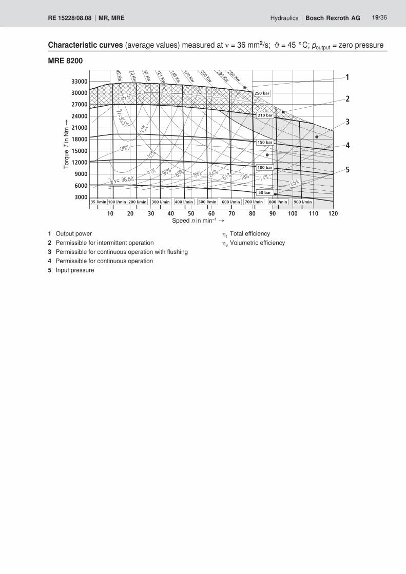
Characteristic curves (average values) measured at ν = 36 mm2/s; ϑ = 45 °C; poutput = zero pressure
MRE 8200
3000
6000
9000
12000
15000
18000
21000
24000
27000
30000
33000
100 bar
250 bar
50 bar
150 bar
210 bar
35 l/min 100 l/min 200 l/min 400 l/min300 l/min 800 l/min700 l/min600 l/min500 l/min 900 l/min
10 20 30 40 60 70 80 90 100 110 12050
1
2
3
4
5Torq
ue T
in N
m →
Speed n in min–1 →
1 Output power2 Permissible for intermittent operation3 Permissible for continuous operation with flushing4 Permissible for continuous operation5 Input pressure
ηt Total efficiencyηv Volumetric efficiency
20/36 Bosch Rexroth AG Hydraulics MR, MRE RE 15228/08.08
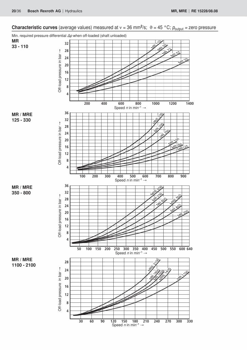
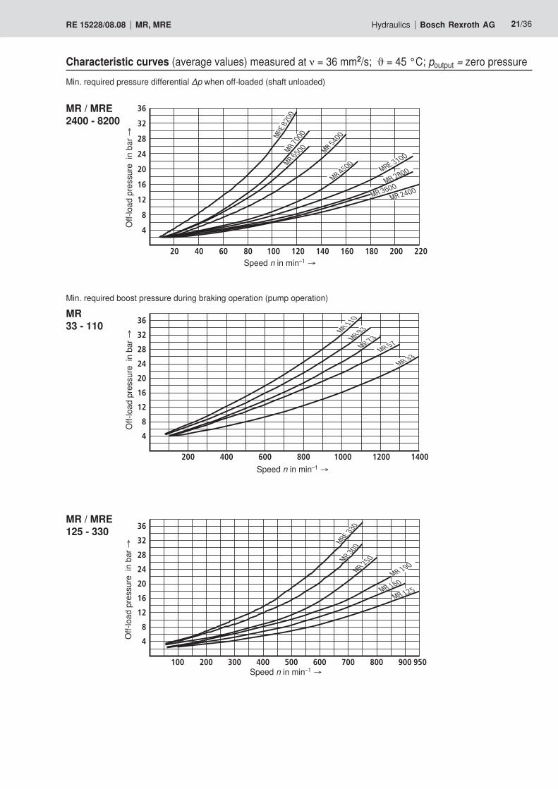
Characteristic curves (average values) measured at ν = 36 mm2/s; ϑ = 45 °C; poutput = zero pressureMin. required pressure differential ∆p when off-loaded (shaft unloaded)
4
16
12
8
28
24
20
32
200 400 800600 1000 1200 1400
8
4
20
16
12
32
28
24
36
50 150100 200 600300250 400350 500450 550 640
4
8
28
24
20
16
12
30012030 60 90 150 180 210 240 270 330
12
4
8
24
20
16
36
32
28
200100 300 500400 700600 800 900
�����
�����
�
������
�����
���
����
�����
�
�����
�
�����
�����
�����
�����
����������
��
������
�
�����
�
�����
����
����
�����
�����
����
�
�����
��
���
����
�
������
�
MR33 - 110
MR / MRE125 - 330
MR / MRE350 - 800
MR / MRE1100 - 2100
Off-
load
pre
ssur
e in
bar
→O
ff-lo
ad p
ress
ure
in b
ar →
Off-
load
pre
ssur
e in
bar
→O
ff-lo
ad p
ress
ure
in b
ar →
Speed n in min–1 →
Speed n in min–1 →
Speed n in min–1 →
Speed n in min–1 →
Hydraulics Bosch Rexroth AGRE 15228/08.08 MR, MRE 21/36
Min. required pressure differential ∆p when off-loaded (shaft unloaded)
MR / MRE2400 - 8200
MR33 - 110
MR / MRE125 - 330
Min. required boost pressure during braking operation (pump operation)
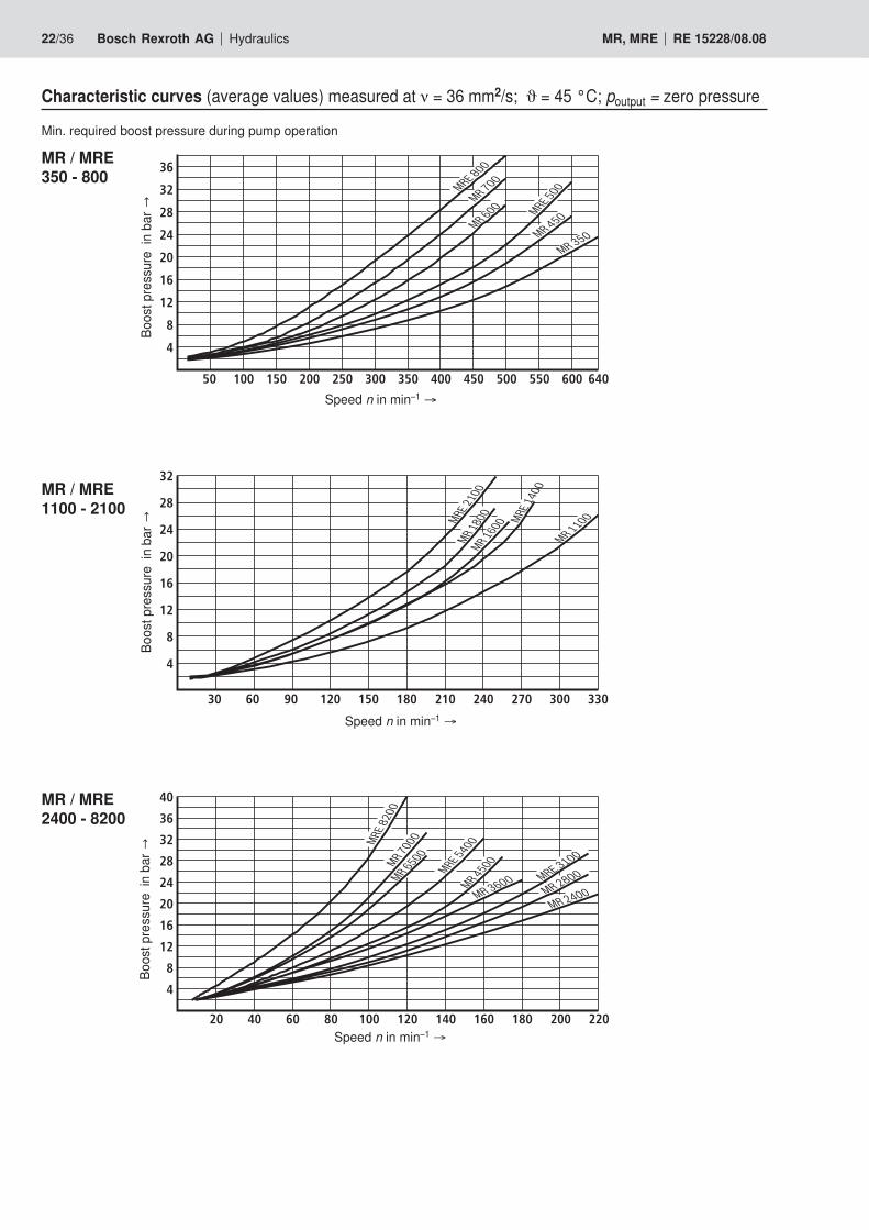
Characteristic curves (average values) measured at ν = 36 mm2/s; ϑ = 45 °C; poutput = zero pressure
�����
�
�����
�����
�����
�����
������
������
������
�����
�
�����
��
�����
�
8
4
36
32
28
24
20
16
12
4
16
12
8
28
24
20
36
32
8
4
24
20
16
12
36
32
28
200100 300 500400 600 800700 950900
200 400 800600 1000 1200 1400
604020 20012010080 180160140 220
��������
�����
��
�����
��
�����
���
�����
��
�������
�����
��
�������
�������
Off-
load
pre
ssur
e in
bar
→
Speed n in min–1 →
Off-
load
pre
ssur
e in
bar
→
Speed n in min–1 →
Off-
load
pre
ssur
e in
bar
→
Speed n in min–1 →
22/36 Bosch Rexroth AG Hydraulics MR, MRE RE 15228/08.08
Characteristic curves (average values) measured at ν = 36 mm2/s; ϑ = 45 °C; poutput = zero pressure
MR / MRE350 - 800
Min. required boost pressure during pump operation
MR / MRE1100 - 2100
MR / MRE2400 - 8200
�����
���
�������
�����
��
�����
��
�����
���
�����
��
�������
�������
�����
���
�����
���
�����
�� �����
���
�����
��
�����
��
�����
�
�����
��
�����
�
�����
������
�
�����
��
8
4
24
16
12
20
36
32
28
40
4
16
12
8
24
20
32
28
16
4
12
8
20
24
28
32
36
640100 200 300 400 500 600150 250 350 450 55050
30 2409060 120 180150 210 330270 300
10020 6040 80 120 140 160 200180 220
Boostpressureinbar→
Speed n in min–1 →
Boostpressureinbar→
Speed n in min–1 →
Boostpressureinbar→
Speed n in min–1 →
Hydraulics Bosch Rexroth AGRE 15228/08.08 MR, MRE 23/36
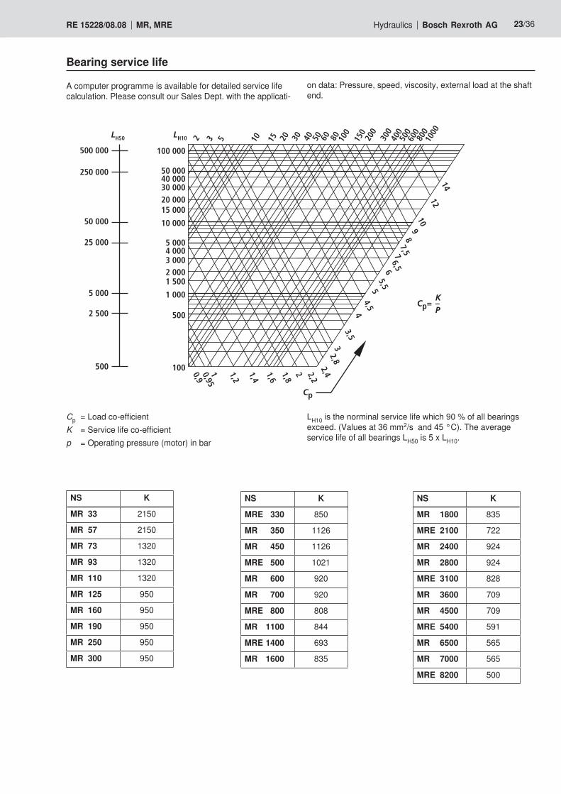
Bearing service life
on data: Pressure, speed, viscosity, external load at the shaft end.
A computer programme is available for detailed service life calculation. Please consult our Sales Dept. with the applicati-
100
500
1 000
1 5002 0003 0004 0005 000
10 000
15 000 20 00030 00040 00050 000
100 000
2 3 5 10 15 20 30 40 50 60 80 100
150
200
300
400
500
600
800
1000
14
12
109
87,57
6,565,55
4,54
3,5
32,8
2,42,2
21,8
1,6
1,4
1,2
10,95
0,9500
2 500
5 000
25 000
50 000
250 000
500 000
LH10
KCp= –
P
LH50
Cp
Cp = Load co-efficientK = Service life co-efficientp = Operating pressure (motor) in bar
LH10 is the norminal service life which 90 % of all bearings exceed. (Values at 36 mm2/s and 45 °C). The average service life of all bearings LH50 is 5 x LH10.
NS K
MRE 330 850
MR 350 1126
MR 450 1126
MRE 500 1021
MR 600 920
MR 700 920
MRE 800 808
MR 1100 844
MRE 1400 693
MR 1600 835
NS K
MR 1800 835
MRE 2100 722
MR 2400 924
MR 2800 924
MRE 3100 828
MR 3600 709
MR 4500 709
MRE 5400 591
MR 6500 565
MR 7000 565
MRE 8200 500
NS K
MR 33 2150
MR 57 2150
MR 73 1320
MR 93 1320
MR 110 1320
MR 125 950
MR 160 950
MR 190 950
MR 250 950
MR 300 950
24/36 Bosch Rexroth AG Hydraulics MR, MRE RE 15228/08.08
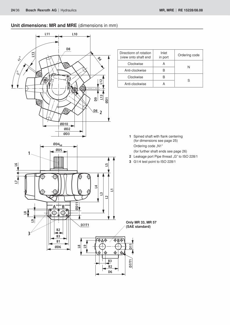
1 Spined shaft with flank centering (for dimensions see page 25) Ordering code „N1” (for further shaft ends see page 26)
2 Leakage port Pipe thread „G” to ISO 228/13 G1/4 test point to ISO 228/1
Only MR 33, MR 57 (SAE standard)
Unit dimensions: MR and MRE (dimensions in mm)
D8
ØD3ØD2
ØD10
L13
L11 L10
L12
L13
D9
ØD
1
D8
B4
2
ØD6
B1B3
B2
L9
L8
L4
L3
L2
L1
L5
L7
D5
D4h8
D7/T1
L6
D11A B
3
1
B2
B3
D6
D7/
T1
L8 L9
A B
D11
Directionn of rotation (view onto shaft end
Inlet in port Ordering code
Clockwise AN
Anti-clockwise B
Clockwise BS
Anti-clockwise A
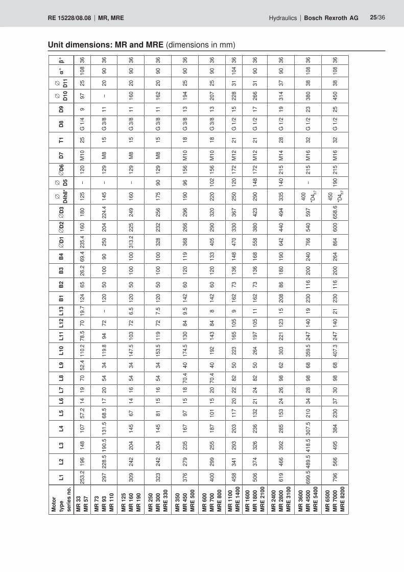
Hydraulics Bosch Rexroth AGRE 15228/08.08 MR, MRE 25/36
Mot
or
type
serie
s no
.L1
L2L3
L4L5
L6L7
L8L9
L10
L11
L12
L13
B1B2
B3B4
D1D2
D3D4
h8*
D5D6
D7T1
D8D9
D10
D11
α°β°
MR
33M
R 57
253.
219
614
810
757
.214
1970
52.4
110.
278
.570
19.7
124
6526
.269
.423
5.4
160
180
125
–12
0M
1025
G 1
/49
9725
108
36
MR
73M
R 93
MR
110
297
228.
519
0.5
131.
568
.517
2054
3411
9.8
9472
–12
050
100
9025
020
422
4.4
145
–12
9M
815
G 3
/811
–20
9036
MR
125
MR
160
MR
190
309
242
204
145
6714
1654
3414
7.5
103
726.
512
050
100
100
313.
222
524
916
0–
129
M8
15G
3/8
1116
020
9036
MR
250
MR
300
MRE
330
323
242
204
145
8115
1654
3415
3.5
119
727.
512
050
100
100
328
232
256
175
9012
9M
815
G 3
/811
162
2090
36
MR
350
MR
450
MRE
500
376
279
235
167
9715
1870
.440
174.
513
084
9.5
142
6012
011
936
826
629
619
096
156
M10
18G
3/8
1319
425
9036
MR
600
MR
700
MRE
800
400
299
255
187
101
1520
70.4
4019
214
384
814
260
120
133
405
290
320
220
102
156
M10
18G
3/8
1320
725
9036
MR
1100
MRE
140
045
834
129
320
311
720
2282
5022
316
510
59
162
7313
614
847
033
036
725
012
017
2M
1221
G 1
/215
228
3110
436
MR
1600
MR
1800
MRE
210
050
637
432
623
613
221
2482
5026
419
710
511
162
7313
616
855
838
042
329
014
817
2M
1221
G 1
/217
266
3190
36
MR
2400
MR
2800
MRE
310
061
946
639
228
515
324
2698
6230
322
112
315
208
8618
019
064
244
049
433
514
021
5M
1428
G 1
/219
314
3790
36
MR
3600
MR
4500
MRE
540
069
9.5
489.
541
8.5
307.
521
034
2898
6835
9.5
247
140
1923
011
620
024
076
654
059
740
0*D
4 h7–
215
M16
32G
1/2
2338
038
108
36
MR
6500
MR
7000
MRE
820
079
656
649
538
423
037
3098
6840
7.3
247
140
2123
011
620
026
486
460
065
8.6
450
*D4 h7
190
215
M16
32G
1/2
2545
038
108
36
Unit dimensions: MR and MRE (dimensions in mm)
26/36 Bosch Rexroth AG Hydraulics MR, MRE RE 15228/08.08
1st shaft end
N D
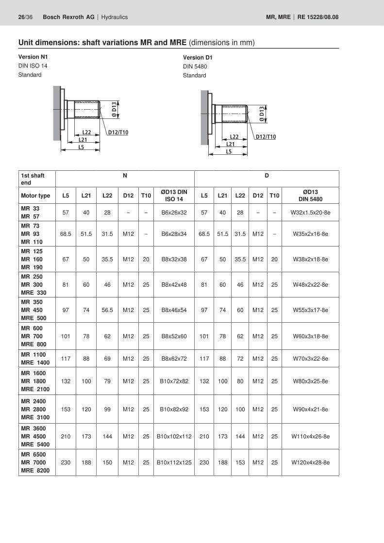
Motor type L5 L21 L22 D12 T10 ØD13 DIN ISO 14 L5 L21 L22 D12 T10 ØD13
DIN 5480MR 33MR 57 57 40 28 – – B6x26x32 57 40 28 – – W32x1.5x20-8e
MR 73MR 93MR 110
68.5 51.5 31.5 M12 – B6x28x34 68.5 51.5 31.5 M12 – W35x2x16-8e
MR 125MR 160MR 190
67 50 35.5 M12 20 B8x32x38 67 50 35.5 M12 20 W38x2x18-8e
MR 250MR 300MRE 330
81 60 46 M12 25 B8x42x48 81 60 46 M12 25 W48x2x22-8e
MR 350MR 450MRE 500
97 74 56.5 M12 25 B8x46x54 97 74 60 M12 25 W55x3x17-8e
MR 600MR 700MRE 800
101 78 62 M12 25 B8x52x60 101 78 62 M12 25 W60x3x18-8e
MR 1100MRE 1400 117 88 69 M12 25 B8x62x72 117 88 72 M12 25 W70x3x22-8e
MR 1600MR 1800MRE 2100
132 100 79 M12 25 B10x72x82 132 100 80 M12 25 W80x3x25-8e
MR 2400MR 2800MRE 3100
153 120 99 M12 25 B10x82x92 153 120 100 M12 25 W90x4x21-8e
MR 3600MR 4500MRE 5400
210 173 144 M12 25 B10x102x112 210 173 144 M12 25 W110x4x26-8e
MR 6500MR 7000MRE 8200
230 188 150 M12 25 B10x112x125 230 188 153 M12 25 W120x4x28-8e
Unit dimensions: shaft variations MR and MRE (dimensions in mm)
Ø D
13
L22
L5L21
D12/T10
Ø D
13
L22
L5L21
D12/T10
Version D1DIN 5480 Standard
Version N1DIN ISO 14Standard
Hydraulics Bosch Rexroth AGRE 15228/08.08 MR, MRE 27/36
1st shaft end
F P
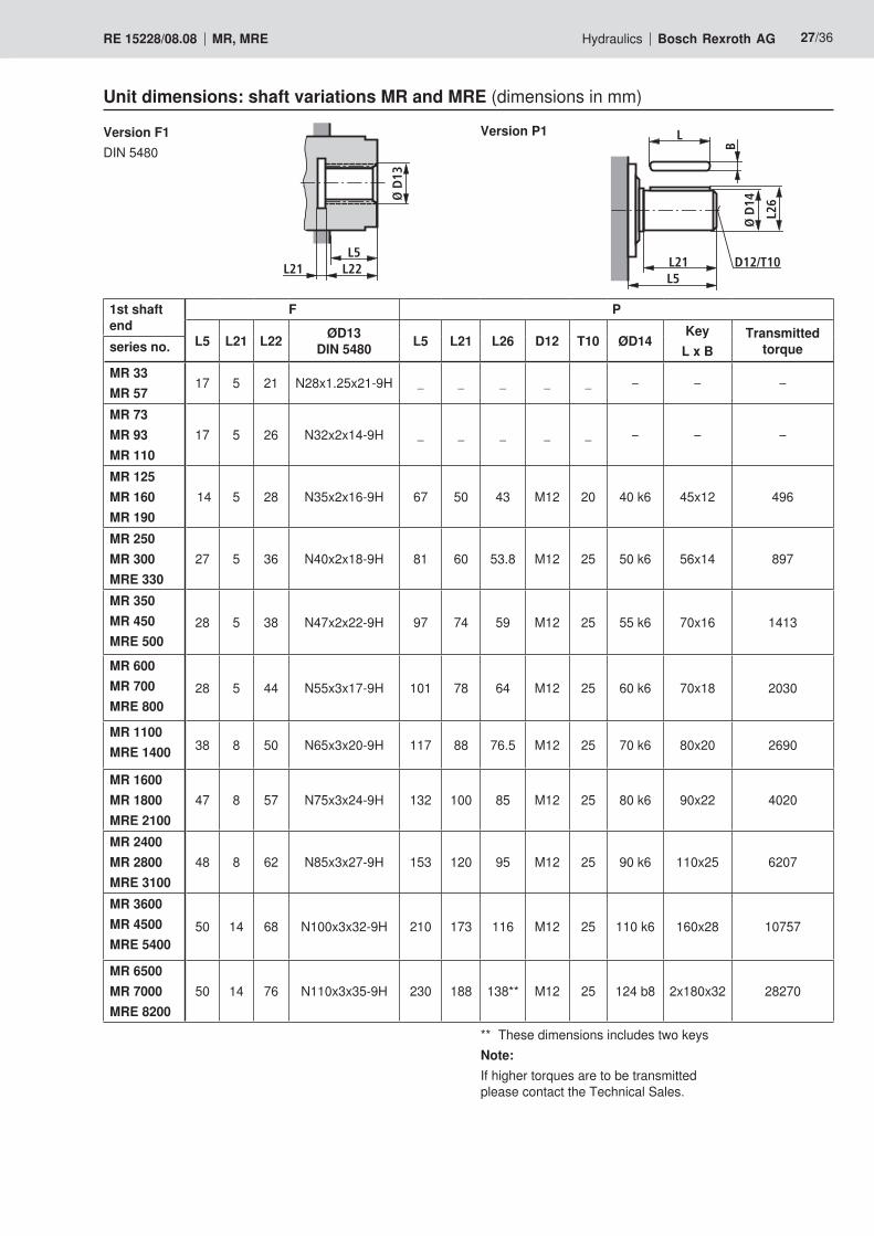
L5 L21 L22 ØD13DIN 5480 L5 L21 L26 D12 T10 ØD14
Key L x B
Transmitted torque series no.
MR 33MR 57
17 5 21 N28x1.25x21-9H _ _ _ _ _ – – –
MR 73MR 93MR 110
17 5 26 N32x2x14-9H _ _ _ _ _ – – –
MR 125MR 160MR 190
14 5 28 N35x2x16-9H 67 50 43 M12 20 40 k6 45x12 496
MR 250MR 300MRE 330
27 5 36 N40x2x18-9H 81 60 53.8 M12 25 50 k6 56x14 897
MR 350MR 450MRE 500
28 5 38 N47x2x22-9H 97 74 59 M12 25 55 k6 70x16 1413
MR 600MR 700MRE 800
28 5 44 N55x3x17-9H 101 78 64 M12 25 60 k6 70x18 2030
MR 1100MRE 1400 38 8 50 N65x3x20-9H 117 88 76.5 M12 25 70 k6 80x20 2690
MR 1600MR 1800MRE 2100
47 8 57 N75x3x24-9H 132 100 85 M12 25 80 k6 90x22 4020
MR 2400MR 2800MRE 3100
48 8 62 N85x3x27-9H 153 120 95 M12 25 90 k6 110x25 6207
MR 3600MR 4500MRE 5400
50 14 68 N100x3x32-9H 210 173 116 M12 25 110 k6 160x28 10757
MR 6500MR 7000MRE 8200
50 14 76 N110x3x35-9H 230 188 138** M12 25 124 b8 2x180x32 28270
** These dimensions includes two keysNote:If higher torques are to be transmitted please contact the Technical Sales.
Unit dimensions: shaft variations MR and MRE (dimensions in mm)
L
BØ
D14
L26
L21L5
D12/T10
Ø D
13
L22L5
L21
Version F1DIN 5480
Version P1
28/36 Bosch Rexroth AG Hydraulics MR, MRE RE 15228/08.08
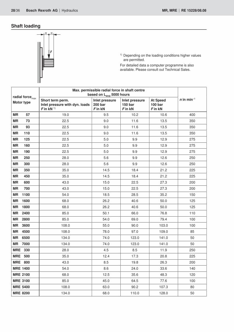
Shaft loading
1) Depending on the loading conditions higher values are permitted. For detailed data a computer programme is also available. Please consult out Technical Sales.
radial forcemax Motor type
Max. permissible radial force in shaft centre based on LH10 5000 hours
n in min–1Short term perm. Inlet pressure with dyn. loads F in kN 1)
Inlet pressure 200 bar F in kN
Inlet pressure 150 bar F in kN
At Speed 100 bar F in kN
MR 57 19.0 9.5 10.2 10.6 400MR 73 22.5 9.0 11.6 13.5 350MR 93 22.5 9.0 11.6 13.5 350MR 110 22.5 9.0 11.6 13.5 350MR 125 22.5 5.0 9.9 12.9 275MR 160 22.5 5.0 9.9 12.9 275MR 190 22.5 5.0 9.9 12.9 275MR 250 28.0 5.6 9.9 12.6 250MR 300 28.0 5.6 9.9 12.6 250MR 350 35.0 14.5 18.4 21.2 225MR 450 35.0 14.5 18.4 21.2 225MR 600 43.0 15.0 22.5 27.3 200MR 700 43.0 15.0 22.5 27.3 200MR 1100 54.0 18.5 28.5 35.2 150MR 1600 68.0 26.2 40.6 50.0 125MR 1800 68.0 26.2 40.6 50.0 125MR 2400 85.0 50.1 66.0 76.8 110MR 2800 85.0 54.0 69.0 79.4 100MR 3600 108.0 55.0 90.0 103.0 100MR 4500 108.0 78.0 97.0 109.0 85MR 6500 134.0 74.0 123.0 141.0 50MR 7000 134.0 74.0 123.0 141.0 50MRE 330 28.0 4.5 8.5 11.9 250MRE 500 35.0 12.4 17.3 20.8 225MRE 800 43.0 8.5 19.8 26.3 200MRE 1400 54.0 8.6 24.0 33.6 140MRE 2100 68.0 12.5 35.6 48.3 120MRE 3100 85.0 45.0 64.5 77.6 100MRE 5400 108.0 63.0 90.2 107.3 80MRE 8200 134.0 68.0 110.0 128.0 50
= =
F
Hydraulics Bosch Rexroth AGRE 15228/08.08 MR, MRE 29/36
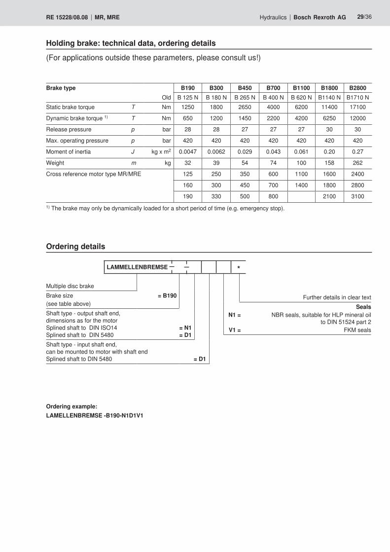
Brake typeOld
B190 B300 B450 B700 B1100 B1800 B2800B125N B180N B265N B400N B620N B1140N B1710N
Static brake torque T Nm 1250 1800 2650 4000 6200 11400 17100
Dynamic brake torque 1) T Nm 650 1200 1450 2200 4200 6250 12000
Release pressure p bar 28 28 27 27 27 30 30
Max. operating pressure p bar 420 420 420 420 420 420 420
Moment of inertia J kg x m2 0.0047 0.0062 0.029 0.043 0.061 0.20 0.27
Weight m kg 32 39 54 74 100 158 262
Cross reference motor type MR/MRE 125 250 350 600 1100 1600 2400
160 300 450 700 1400 1800 2800
190 330 500 800 2100 3100
(For applications outside these parameters, please consult us!)
1) The brake may only be dynamically loaded for a short period of time (e.g. emergency stop).
Holding brake: technical data, ordering details
Ordering details
Ordering example:LAMELLENBREMSE -B190-N1D1V1
LAMMELLENBREMSE *
Multiple disc brakeBrakesize = B190(see table above)Shaft type - output shaft end, dimensions as for the motor Splined shaft to DIN ISO14 = N1Splined shaft to DIN 5480 = D1Shaft type - input shaft end, can be mounted to motor with shaft end Splined shaft to DIN 5480 = D1
Further details in clear textSeals
N1 = NBRseals,suitableforHLPmineraloil to DIN 51524 part 2
V1 = FKM seals
30/36 Bosch Rexroth AG Hydraulics MR, MRE RE 15228/08.08
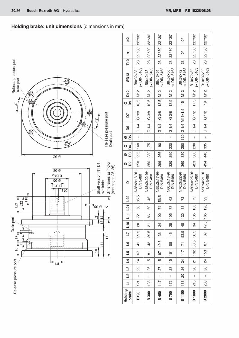
Hold
ing
brak
eL1
L2L3
L4L5
L6L7
L10
L11
L21
L22
D1Ø D2
Ø D3Ø D4
h8
Ø D5D6
D7Ø D9
D12
ØD1
3T1
0α1
α2
B190
121
–22
1467
4129
.320
7250
35.5
N38x
2x18
-9H
DIN
5480
250
225
160
–G
1/4
G 3
/810
.5M
12B8
x32x38
ex D
IN 5
463
2822
°30‘
22°3
0‘
B 30
013
6–
2515
8142
39.5
2186
6046
N48x
2x22
-9H
DIN
5480
256
232
175
–G
1/4
G 3
/810
.5M
12B8
x42x48
ex D
IN 5
463
2822
°30‘
22°3
0‘
B 45
014
7–
2715
9749
.536
2410
074
56.5
N55x
3x17
-9H
DIN
5480
296
266
190
–G
1/4
G 3
/813
.5M
12B8
x46x54
ex D
IN 5
463
2822
°30‘
22°3
0‘
B 70
017
2–
2815
101
5546
2510
578
62N6
0x3x
18-9
HDI
N 54
8032
029
022
0–
G 1
/4G
3/8
13.5
M12
B8x52x60
ex D
IN 5
463
2822
°30‘
22°3
0‘
B 11
0018
820
2624
117
7153
.548
120
8872
N70x
3x22
-9H
DIN
5480
360
330
250
120
G 1
/4M
16x1
.515
M12
B8x62x72
ex D
IN 5
463
280°
0°
B 18
0021
6–
2821
132
63.5
58.5
3413
510
079
N80x
3x25
-9H
DIN
5480
423
380
290
–G
1/4
G 1
/217
.5M
12B1
0x72x82
ex D
IN 5
463
2822
°30‘
22°3
0‘
B 28
0026
3–
3024
153
8767
42.5
165
120
99N9
0x4x
21-9
HDI
N 54
8049
444
033
5–
G 1
/4G
1/2
19M
12B1
0x82x92
ex D
IN 5
463
2822
°30‘
22°3
0‘
Holding brake: unit dimensions (dimensions in mm)
L2 L4L3
L11
L1
L10
D1
L6L7
D7
D6
L21 L22 T1
0
D12Ø D13
Ø D5Ø D4h8
Ø D3
L5
Ø D9
Ø D2
Rele
ase
pres
sure
por
t Dr
ain
port
Drai
n po
rtRe
leas
e pr
essu
re p
ort
Shaf
t ver
sion
N1 D
1,
avai
labl
edi
men
sions
as
mot
or
(see
pag
es 2
5, 2
6)
Rele
ase
pres
sure
por
t Dr
ain
port
Hydraulics Bosch Rexroth AGRE 15228/08.08 MR, MRE 31/36
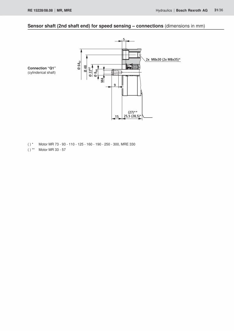
Sensor shaft (2nd shaft end) for speed sensing – connections (dimensions in mm)
Connection “Q1” (cylinderical shaft)
( ) * Motor MR 73 - 93 - 110 - 125 - 160 - 190 - 250 - 300, MRE 330( ) ** Motor MR 33 - 57
2x M8x30 (2x M8x35)*
5
Ø 2
2H7
Ø 4
8
Ø 6
4 f7
25,5 (28,5)*15
Ø 8
h8
M4
9
(27)**
5 m
α
61 L1
Ø 9
332/36 Bosch Rexroth AG Hydraulics MR, MRE RE 15228/08.08
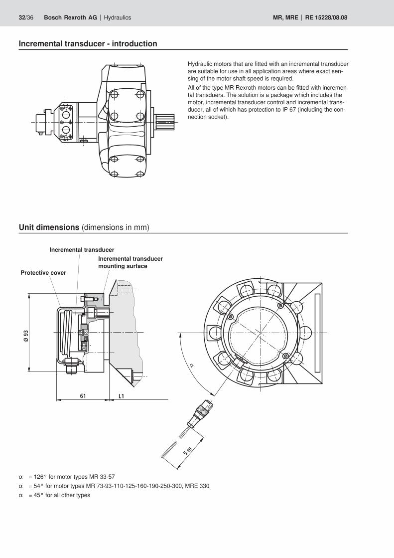
Incremental transducer - introduction
Hydraulic motors that are fitted with an incremental transducer are suitable for use in all application areas where exact sen-sing of the motor shaft speed is required.All of the type MR Rexroth motors can be fitted with incremen-tal transduers. The solution is a package which includes the motor, incremental transducer control and incremental trans-ducer, all of wihich has protection to IP 67 (including the con-nection socket).
Unit dimensions (dimensions in mm)
α =126°formotortypesMR33-57α =54°formotortypesMR73-93-110-125-160-190-250-300,MRE330α =45°forallothertypes
Incremental transducer
Protective cover
Incremental transducer mounting surface
34
1
4
1
3
11
44
33
3
2
4
1
4
1
3
11
44
22
33
2
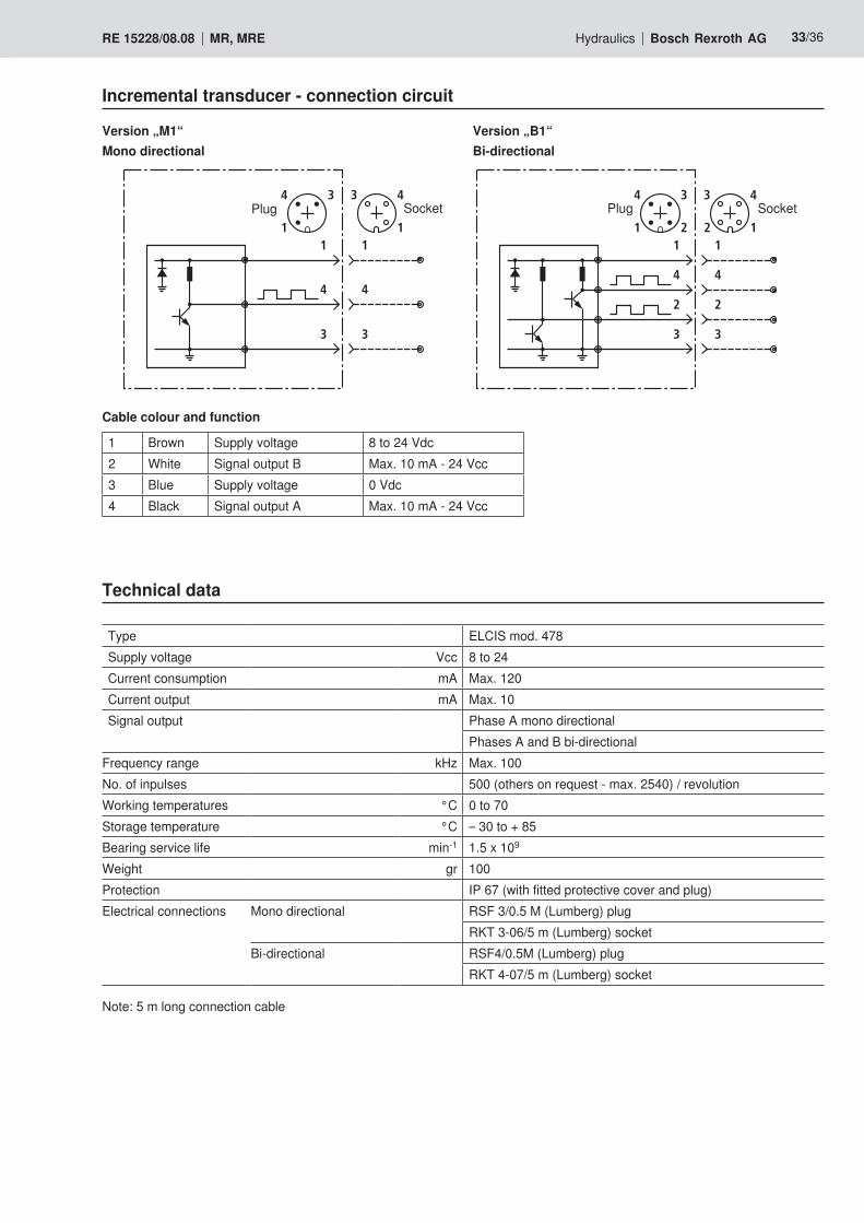
Hydraulics Bosch Rexroth AGRE 15228/08.08 MR, MRE 33/36
Technical data
Type ELCIS mod. 478Supply voltage Vcc 8 to 24Current consumption mA Max. 120Current output mA Max. 10Signal output Phase A mono directional
PhasesAandBbi-directionalFrequency range kHz Max. 100No. of inpulses 500 (others on request - max. 2540) / revolutionWorking temperatures °C 0 to 70Storage temperature °C – 30 to + 85Bearingservicelife min-1 1.5 x 10⁹
Weight gr 100Protection IP 67 (with fitted protective cover and plug)Electrical connections Mono directional RSF 3/0.5 M (Lumberg) plug
RKT 3-06/5 m (Lumberg) socketBi-directional RSF4/0.5M (Lumberg) plug RKT 4-07/5 m (Lumberg) socket
Cable colour and function
1 Brown Supply voltage 8 to 24 Vdc2 White SignaloutputB Max. 10 mA - 24 Vcc3 Blue Supply voltage 0 Vdc4 Black Signal output A Max. 10 mA - 24 Vcc
Note: 5 m long connection cable
Version „B1“Bi-directional
Version „M1“Mono directional
Plug SocketPlug Socket
Incremental transducer - connection circuit
34/36 Bosch Rexroth AG Hydraulics MR, MRE RE 15228/08.08
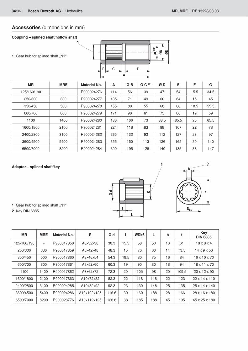
Accessories (dimensions in mm)
1 Gear hub for splined shaft „N1“
Coupling – splined shaft/hollow shaft
MR MRE Material No. A Ø B Ø CH11 Ø D E F G
125/160/190 – R900024276 114 56 39 47 54 15.5 34.5
250/300 330 R900024277 135 71 49 60 64 15 45
350/450 500 R900024278 155 80 55 68 68 18.5 55.5
600/700 800 R900024279 171 90 61 75 80 19 59
1100 1400 R900024280 186 106 73 88.5 85.5 20 65.5
1600/1800 2100 R900024281 224 118 83 98 107 22 78
2400/2800 3100 R900024282 265 132 93 112 127 23 97
3600/4500 5400 R900024283 355 150 113 126 165 30 140
6500/7000 8200 R900024284 390 195 126 140 185 38 147
I
Ø d
L
R
Dk6
b
t
21Adaptor – splined shaft/key
1 Gear hub for splined shaft „N1“2 Key DIN 6885
F G E
A
ØCH
11
ØD
ØB
1
MR MRE Material No. R Ø d I ØDk6 L b t Key DIN 6885
125/160/190 – R900017858 A8x32x38 38.3 15.5 58 50 10 61 10 x 8 x 4
250/300 330 R900017859 A8x42x48 48.3 15 70 60 14 73.5 14 x 9 x 56
350/450 500 R900017860 A8x46x54 54.3 18.5 80 75 16 84 16 x 10 x 70
600/700 800 R900017861 A8x52x60 60.3 19 90 80 18 94 18 x 11 x 70
1100 1400 R900017862 A8x62x72 72.3 20 105 98 20 109.5 20 x 12 x 90
1600/1800 2100 R900017863 A10x72x82 82.3 22 118 118 22 123 22 x 14 x 110
2400/2800 3100 R900024285 A10x82x92 92.3 23 130 148 25 135 25 x 14 x 140
3600/4500 5400 R900024286 A10x102x125 116.6 30 160 188 28 166 28 x 16 x 180
6500/7000 8200 R900023776 A10x112x125 126.6 38 185 188 45 195 45 x 25 x 180
Hydraulics Bosch Rexroth AGRE 15228/08.08 MR, MRE 35/36
MR MRE D H Material No.125/160/190250/300
–330
G 3/4 36 R900017864
350/450 600/700
500 800 G 1 1/4 40 R900017865
110016001800
14002100 G 1 1/2 45 R900017866
24002800
–3100 G 1 1/2 60 R900024266
3600/45006500/7000
54008200 G 2 60 R900023777
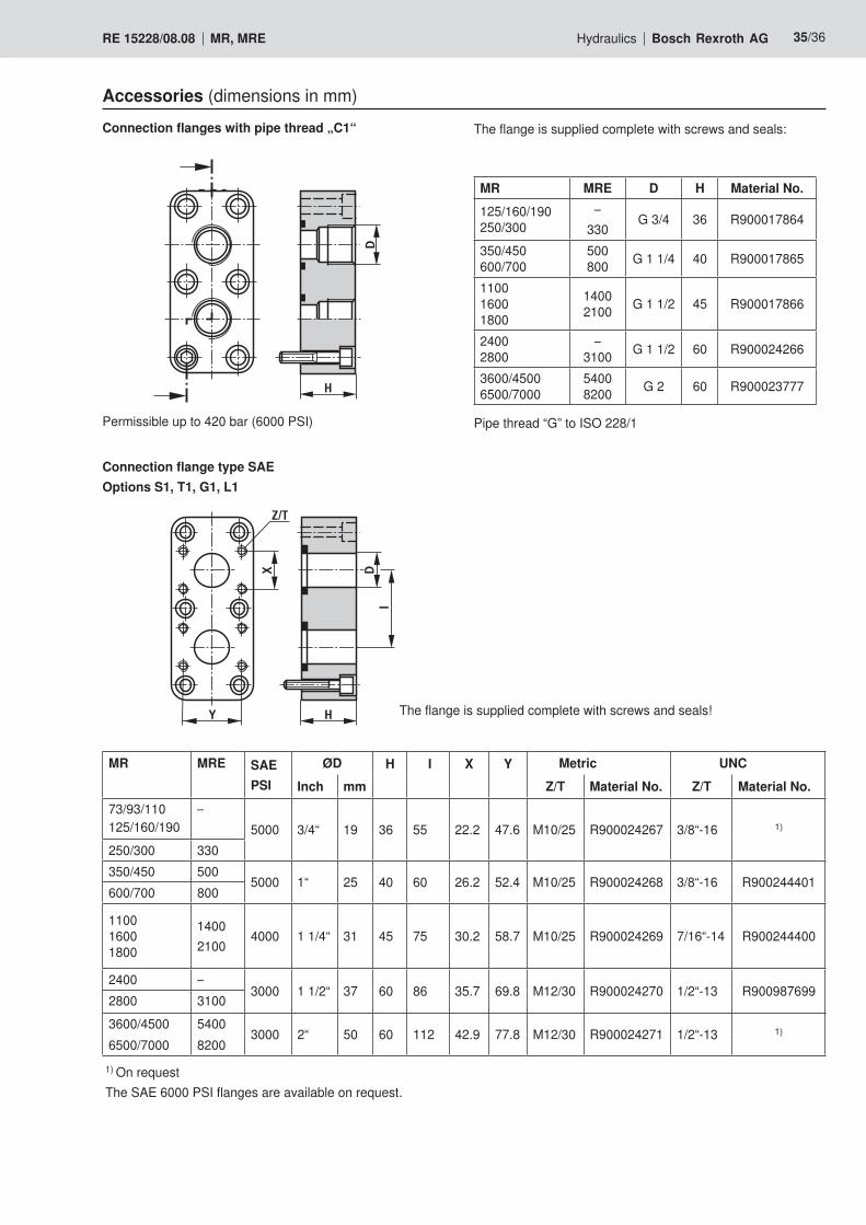
Accessories (dimensions in mm)Connection flanges with pipe thread „C1“
H
D
The flange is supplied complete with screws and seals:
Permissible up to 420 bar (6000 PSI)
Connection flange type SAEOptions S1, T1, G1, L1
The flange is supplied complete with screws and seals!H
DX
I
Y
Z/T
MR MRE SAEPSI
ØD H I X Y Metric UNCInch mm Z/T Material No. Z/T Material No.
73/93/110 125/160/190
–5000 3/4“ 19 36 55 22.2 47.6 M10/25 R900024267 3/8“-16 1)
250/300 330350/450 500
5000 1“ 25 40 60 26.2 52.4 M10/25 R900024268 3/8“-16 R900244401600/700 800
110016001800
14002100
4000 1 1/4“ 31 45 75 30.2 58.7 M10/25 R900024269 7/16“-14 R900244400
2400 –3000 1 1/2“ 37 60 86 35.7 69.8 M12/30 R900024270 1/2“-13 R900987699
2800 31003600/4500 5400
3000 2“ 50 60 112 42.9 77.8 M12/30 R900024271 1/2“-13 1)6500/7000 8200
1) On requestThe SAE 6000 PSI flanges are available on request.
Pipe thread “G” to ISO 228/1
BoschRexrothAG HydraulicsZum Eisengießer 197816 Lohr am Main, Germany Telefon +49 (0) 93 52 / 18-0 Telefax +49 (0) 93 52 / 18-23 [email protected] www.boschrexroth.de
BoschRexrothLimited Cromwell Road, St Neots, Cambs, PE19 2ES Tel: 0 14 80/22 32 56 Fax: 0 14 80/21 90 52 E-mail: [email protected]
The data specified above only serve to describe the product. No state-ments concerning a certain condition or suitability for a certain applicati-on can be derived from our information. It must be remembered that our products are subject to a natural process of wear and ageing.
36/36 Bosch Rexroth AG Hydraulics MR, MRE RE 15228/08.08
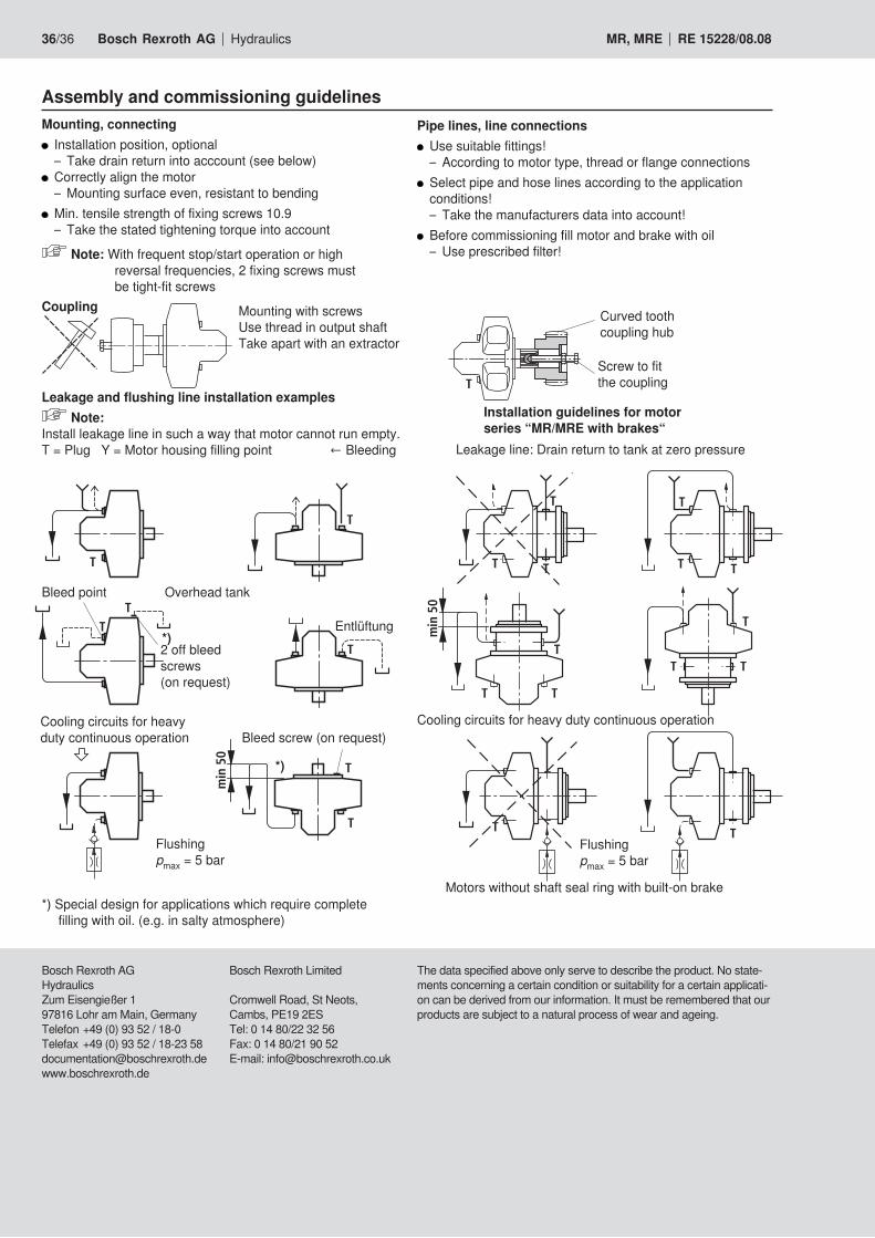
Assembly and commissioning guidelinesMounting, connecting Installation position, optional
– Take drain return into acccount (see below) Correctly align the motor
– Mounting surface even, resistant to bending Min. tensile strength of fixing screws 10.9
– Take the stated tightening torque into account
Note: With frequent stop/start operation or high reversal frequencies, 2 fixing screws must be tight-fit screws
T
TT
min
50
TT
T
TT
T
T
T T T
T T
TT
min
50
T
T T T
Pipe lines, line connections Use suitable fittings!
– According to motor type, thread or flange connections Select pipe and hose lines according to the application conditions!
– Take the manufacturers data into account! Beforecommissioningfillmotorandbrakewithoil
– Use prescribed filter!
T
Installation guidelines for motor series “MR/MRE with brakes“
Leakage line: Drain return to tank at zero pressure
Mounting with screwsUse thread in output shaftTake apart with an extractor
Coupling
Leakage and flushing line installation examples Note:
Install leakage line in such a way that motor cannot run empty. T=PlugY=Motorhousingfillingpoint ←Bleeding
2 off bleed screws(on request)
Entlüftung
Overhead tank
Cooling circuits for heavy duty continuous operationBleedscrew(onrequest)
Flushingpmax = 5 bar
Motors without shaft seal ring with built-on brake*) Special design for applications which require complete filling with oil. (e.g. in salty atmosphere)
Curved tooth coupling hub
Screw to fit the coupling
Bleedpoint
Cooling circuits for heavy duty continuous operation
Flushingpmax = 5 bar
*)
*)