Radial Piston Motors Series 60 Technical Information …files.danfoss.com/documents/Radial Piston...
32
powersolutions.danfoss.com MAKING MODERN LIVING POSSIBLE Technical Information Radial Piston Motors Series 60 Phased Out Products
Transcript of Radial Piston Motors Series 60 Technical Information …files.danfoss.com/documents/Radial Piston...
powersolutionsdanfosscom
MAKING MODERN LIVING POSSIBLE
Technical Information
Radial Piston MotorsSeries 60
Phased Out Products
Technical Information Radial Piston Motors Series 60
5369264 bull Rev BA bull Sep 20132
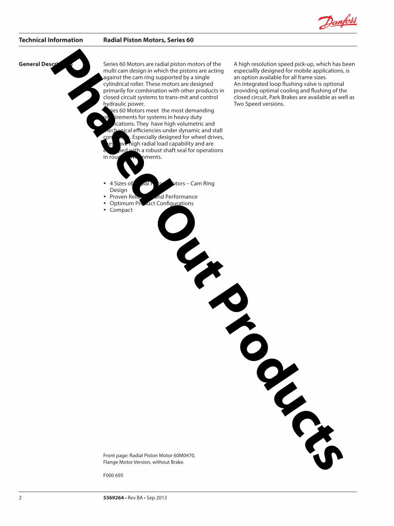
Series 60 Motors are radial piston motors of the multi cam design in which the pistons are acting against the cam ring supported by a single cylindrical roller These motors are designed primarily for combination with other products in closed circuit systems to trans-mit and control hydraulic power Series 60 Motors meet the most demanding requirements for systems in heavy duty applications They have high volumetric and mechanical efficiencies under dynamic and stall conditions Especially designed for wheel drives they have high radial load capability and are equipped with a robust shaft seal for operations in rough environments
A high resolution speed pick-up which has been especiallly designed for mobile applications is an option available for all frame sizes An integrated loop flushing valve is optional providing optimal cooling and flushing of the closed circuit Park Brakes are available as well as Two Speed versions
General Description
y 4 Sizes of Radial Piston Motors ndash Cam Ring Design
y Proven Reliability and Performance y Optimum Product Configurations y Compact
Front page Radial Piston Motor 60M0470 Flange Motor Version without Brake
F000 695
Phased Out Products
Technical Information Radial Piston Motors Series 60
369264 bull Rev BA bull Sep 2013 3
A Complete Family to Meet Market Needs y Four (4) Frame Sizes
470 cm3 (2868 in3rev) to 1750 cm3 (1068 in3rev)
y Choice of five (5) Displacements per Frame Size from 90 to 130 of Basis Volume
y Wide Range of Installation Options y Closed or Open Circuit Installations
High Performance y Speeds to 310 rpm y Pressure to 480 bar (7000 psi) y High Overall Efficiency y High Starting Torque Efficiency y Low Noise Levels
World Product y Designed for Worldwide Markets y Identical Product Available Worldwide y Mobile and Industrial Markets
The Latest Technology y Unique Product Features y High Power Density y Designed to Lower Installation Costs y Design Provides for Reduced Operating Costs
Reliability y Designed to Rigorous Standards y Manufactured to Exacting Quality Standards y Long Service Life y Output Shaft Bearings provide for High Radial
and Axial Loads
Worldwide Support y Sales and Technical Support in All
Industrialized Countries of the World y Serviced by a Worldwide Network of
Authorized Service Centers
Technical FeaturesPhased Out Products
Technical Information Radial Piston Motors Series 60
5369264 bull Rev BA bull Sep 20134
DescriptionGeneral Description 2Technical Features 3System Circuit Description 5Sectional View 5aType Designation and Order Code 5bNotes 6Technical Specifications 7Technical Data and Determination of Nominal Motor Size (Metric System) 8Technical Data (Continuation) and Determination of Nominal Motor Size (Inch System) 9
General Technical SpecificationsSpeed Range System Pressure Range Case Pressure Hydraulic Fluids Temperature Limits Loop Flushing Valve 10Charge Pressure Requirements Park Brake 11Freewheeling Option Two Speed Option Speed Pick Up 12Efficiency Curves 13Efficiency Curves 13a
DimensionsWheel Motor 0470 13bFlange Motor 0470 14Shaft Motor 047 15Wheel Motor 0780 16Flange Motor 0780 17Shaft Motor 0780 17aWheel Motor 1048 17bFlange Motor 1048 18Shaft Motor 1048 19Wheel Motor 1750 20Flange Motor 1750 21Shaft Motor 1750 21aNotes 21bPark Brakes 22Speed Sensor 23
Contents Phased Out Products
Technical Information Radial Piston Motors Series 60
369264 bull Rev BA bull Sep 2013 5
System Circuit Description
Figure 1 shows a hydrostatic transmission using a Series 90 axial piston variable displacement pump and a Series 60 radial piston motor
Figure 1 System Circuit Diagram bull Radial Piston Motor with Axial Piston Pump
Pump Motor
P001 398 E
Control handle Displacement control valve
Oricedcheck valve
Heat exchangerbypass valve
Heat exchanger
Reservoir(Oil)
Vacuum gauge
Multi-functionvalve
Servo controlcylinder
Pumpswashplate
Inputshaft
topumpcase
Charge pump
Servo pressurerrelief valve
Multi-functionvalve
Charge pressurerelief valve
Radial pistonmotorServo control
cylinder
Reversiblevariabledisplacementpump
Control uid
Suction lineCase drain uid
Working loop (high pressure)
Working loop (low pressure)
Loopushing
valve
Purge pressure relief valve
to motor case
Out put ange
Two SpeedValve
Phased Out Products
Technical Information Radial Piston Motors Series 60
5369264 bull Rev BA bull Sep 20136
Sectional View
Figure 2 Series 60 Radial Piston Motor
AAPiston
Distributor
Frame Mounting Face
BearingRim Mounting Face
P001 396
Loop ushingvalve(Option No loopushing)
Two-SpeedValve
P001 397
Section A - A
Phased Out Products
Technical Information Radial Piston Motors Series 60
369264 bull Rev BA bull Sep 2013 7
Type Designation and Order Code
6 0
Frame Size
Displacement per RevSize0470 = 470 cm3 (287 in3)0780 = 780 cm3 (476 in3)1048 = 1048cm3 (639 in3)1750 =1 750cm3 (1068 in3)
N N NNN N N
Displacement-OptionD090 = 090D100 = 100D110 = 110D120 = 120D130 = 130
Data sheetNN = Std
= Standard = optional
Brake OptionsN = None (Single Speed)K = None (Two Speed)P = With Brake
Control OptionsN N = None
Port StyleT = SAE O Ring Boss (0470 0780)S = SAE FlangeJ518cC 62 (1048 1750)
Brake TypeN = Without brake1 = Type 1 (60)3 = Type 3 (90)
Distributor Cover Options1W = Single Speed Wheel- Flange Motor2W = Two Speed Wheel- Flange Motor1S = Single Speed Shaft Motor2S = Two Speed Shaft Motor
Special HardwareN N N = NoneN N S = Speed Sensor
Pref RotationN = None Single-SpdR =CW Two-SpeedL =CCW Two-Speed
Charge Pressure00 = None14 = 14 bar18 = 18 bar20 = 20 bar24 = 24 bar
Motor DesignM =Single SpeedV =Two Speed
Shaft CongurationS1S = Shaft motor SAE-SplineW1W = Wheel MotorW2C = Flange Motor
Loop FlushingL = WithN = None
Series orProduct60=Series 60Radial PistonMotor
Phased Out Products
Technical Information Radial Piston Motors Series 60
5369264 bull Rev BA bull Sep 20138
Notes Phased Out Products
Technical Information Radial Piston Motors Series 60
369264 bull Rev BA bull Sep 2013 9
Circuit Diagram and Nomenclature
Radial Piston Motor
Figure 3 Circuit diagram middot Radial Piston Motor
PortsA B = Main pessure linesL1 L2 = Drain lines
DesignRadial piston cam ring motor in single and two speed version
Type of MountingFlange mounting with pilot
Pipe ConnectionsMain pressure ports SAE straight thread O-ring boss Size 0470 and 0780 SAE flange Code 62 Size 1048 and 1750 Other ports SAE straight thread O-ring boss Refer to ldquoDimensionsrdquo section for port sizes
Direction of Rotation Clockwise and counter-clockwise (bi-directional)
Installation PositionInstallation position as required The housing must always be filled with hydraulic fluid
Flow DirectionRefer to ldquoDimensions sectionrdquo
Hydraulic Parameters
System Pressure Range Port A and BMax pressure 480 bar (7000 psi)
Min pressure [450 bar (6500 psi) for 130 Option] See Diagram Page 11 Fig 5
Case PressureMax Continuous 3 bar (44 psi) Max intermittent 14 bar (200 psi) (cold start)
Pilot Pressure Two Speed OptionFor minimum displacement signal pressure to displacement change port ldquox1rdquo Min pressure 10 bar (145 psi) (above case pressure) Max pressure 50 bar (725 psi)
Hydraulic FluidRefer to Publication BLN-9887 or 697581 Refer to ATI-E 9101 for information relating to biodegradeable fluids
Temperature Rangeϑ min = -20 degC (-4 degF) intermittent cold startϑ nominal = 80 degC (175 degF) continuousϑ max = 85 degC (188 degF) intermittent 1)
Hydraulic fluid viscosity must be as shown below1) at the hottest point normally the case drain line
Fluid Viscosity Limitsν min = 9 mm2s ( 55 SUS) continuous ν max= 1600 mm2s (7400 SUS) intermittent cold start
FiltrationRequired cleanliness level ISO 4406 Code 1813 or betterRefer to publication BLN-9887 or 697581 and ATI-E 9201
Technical Specificatons - Radial Piston Motors Cam Ring Design
P001 390
B
L1
A
L2
Phased Out Products
Technical Information Radial Piston Motors Series 60
5369264 bull Rev BA bull Sep 201310
Technical Data ndash Radial Piston Motors
Table 1
Determination of Nominal Motor Size (Metric System)
Vg middot nInput flow Qe = mdashmdashmdashmdash lmin 1000 middot ηv
Vg middot Dp middot ηmhOutput torque Me = mdashmdashmdashmdashmdash Nm 20 middot π
Vg = Motor displacement per rev cm3 Dp = pHD - pND bar ηv = Motor volumetric efficiency ηmh = Motor mechanical ndash hydraulic (Torque) efficiency
Me middot n Qe middot Dp middot ηt Output power Pe = mdashmdashmdashmdash = mdashmdashmdashmdashmdash kW 9950 600
Qe middot 1000 middot ηvSpeed n = mdashmdashmdashmdashmdash min-1
Vg
ηv = Motor overall efficiency pHD = High pessure barpND = Low pressure bar
Frame Size
(Dimension) 0470 0780Displacement - Option 90 100 100 110 120 130
Displacement Vg cm 3 423 470 517 564 611 702 780 858 936 1014
in3
Vg 05 cm 3 212 235 259 282 306 351 390 429 468 507in3
Rated Speed n min -1 (RPM) 235 200
Output Speed max n min -1 (RPM) 310 295 280 270 260 260 250 240 230 220Theoretical Torque at Vg Nm bar 673 748 823 898 972 1117 1241 1366 1490 1614
lbfbullin1000 psi 4117 4576 5035 5494 5946 6833 7592 8357 9115 9874
Vg 05 Nm bar 337 374 411 449 486 559 621 683 745 807lbfbullin1000 psi 2062 2288 2514 2747 2973 3420 3799 4178 4558 4937
Max Flow at Vg Q l min 131 138 145 152 159 183 195 206 215 223
galmin (US
Max Flow at Vg 05 Q l min 66 69 72 76 79 91 98 103 108 112
galmin (US
Output PowerSingle Speed at Vg kW 29 41
hp 39 55
Two Speed P kW 19 27pref Direction Vg 05 hp 25 36
Two Speed P kW 14 20
not pref Direction Vg 05 hp 19 27
Weight
Wheel Motor m kg 46 74
lb 101 163
Flange Motor m kg 42 71
lb 93 157
Shaft Motor m kg 49 72lb 108 159
P
110 120 130 90
259 287 315 344 373 428 476 524 571 619
173 183 191 201 210 241 257 272 284 294
129 143 158 172 187 214 238 262 285 309
346 366 382 402 420 482 515 544 568 589
Phased Out Products
Technical Information Radial Piston Motors Series 60
369264 bull Rev BA bull Sep 2013 11
Technical Data ndash Radial Piston Motors (cont)
Table 2
Determination of Nominal Motor Size (Inch System)
Vg middot nInput flow Qe = mdashmdashmdashmdash galmin US 231 middot ηv
Vg middot Dp middot ηmhOutput torque Me = mdashmdashmdashmdashmdash lbf in 24 middot π
Vg = Motor displacement per rev in3 Dp = pHD - pND psi ηv = Motor volumetric efficiency ηmh = Motor mechanical ndash hydraulic (Torque) efficiency
Me middot n Qe middot Dp middot ηt Output power Pe = mdashmdashmdashmdash = mdashmdashmdashmdashmdash HP 5252 1715
Qe middot 231 middot ηvSpeed n = mdashmdashmdashmdashmdash min-1
Vg
ηv = Motor overall efficiency pHD = High pessure psipND = Low pressure psi
Frame Size
(Dimension) 1048 1750Displacement - Option 90 100 110 120 130 100 110 120 130
Displacement Vg cm 3 943 1048 1153 1258 1362 1575 1750 1925 2100 2275in3 575 640 704 768 831 961 107 1175 1281 1388
Vg 05 cm3 472 524 576 629 681 788 875 963 1050 1138in3
Rated Speed n min -1 (RPM) 180 150
Output Speed max n min -1 (RPM) 240 230 215 210 200 200 195 185 175 170Theoretical Torque at Vg Nm bar 1501 167 1835 2002 2168 2507 2785 3064 3342 3621
lbfbullin1000 psi 9183 10217 11226 12248 13263 15337 17038 18745 20445 22152
Vg 05 Nm bar 750 834 918 1001 1084 1253 1393 1532 1671 1810lbfbullin1000 psi 4588 5102 5616 6124 6632 7665 8522 9372 10223 11073
Max Flow at Vg Q l min 226 241 248 264 272 315 341 356 368 387
galmin (US
Max Flow at Vg 05 Q l min 113 121 124 132 136 158 171 178 184 193
galmin (US
Output PowerSingle Speed at Vg P kW 50 70
hp 67 94
Two Speed P kW 33 47 pref Direction Vg 05 hp 44 63Two Speed P kW 25 35
not pref Direction Vg 05 hp 34 47
Weight
Wheel Motor m kg 99 149
lb 218 329
Flange Motor m kg 95 144
lb 209 318
Shaft Motor m kg 96 152lb 212 335
90
288 320 351 384 416 481 534 588 641 694
600 636 655 697 718 832 901 940 970 1021
299 318 327 349 359 416 450 470 485 511
Phased Out Products
Technical Information Radial Piston Motors Series 60
5369264 bull Rev BA bull Sep 201312
Speed RangeThe Rated Speed is the max speed recommended at max permitted operating power at which normal life can be expected All other operating conditions (eg fluid viscosity and temperature charge pressure) must be within recom-mended ranges
Maximum Speed is the max operating speed permitted and cannot be exceeded without reduction in the life of the product or risking immediate failure and loss of driveline power (which may create a safety hazard)
W Braking Warning The loss of hydrostatic driveline power in any mode (eg acceleration deceleration or neutral mode of operation) may cause a loss of braking capacity A braking system which is independent of the hydrostatic transmission must therefore be provided which is adequate to stop and hold the system should the condition develop
System Pressure RangeSystem pressure is a dominant operating variable affecting hydraulic unit life High pressure which results from high load reduces expected life in a manner similar to many mechanical assemblies such as engines and gearboxes The maximum pressure is the highest intermittent pres-sure allowed It is determined by the maximum machine load demand Maximum pressure is assumed to occur a small percentage of operating time usually less than 2 of the total Maximum pressure is normally the relief valve setting It is desirable to have a machine duty cycle with the percentage of time at various loads and speeds An appro-priate design pressure can be calculated by our application department from this information This method of selecting operating pressure is recommended whenever duty cycle information is available
Case PressureUnder normal operating conditions the maximum continu-ous case pressure must not exceed 3 bar (44 psi) Maximum allowable intermittent case pressure during cold start must no exceed 14 bar (200 psi)
Hydraulic FluidsUse only recommended hydraulic fluids in accordance to manual BLN-9887 697581 and ATI-E 9101 While fluids containing anti-wear additives are not necessary for the satisfactory performance of the series 60 units they are often required for associated equipment These fluids must possess good thermal and hydrolytic stability to prevent wear erosion and corrosion of internal compo-nents It is not permissible to mix hydraulic fluids Fire-resistant fluids are also suitable at modified
Temperature LimitsRefer to page 7 for maximum allowable temperatures for petroleum based fluids These temperature limits apply at the hottest point of the transmission which is normally the case drain Heat exchangers should be sized to keep the fluid within the limits
Loop FlushingSeries 60 motors incorporate an integral loop flushing valve Installations that require additional fluid to be removed from the main hydraulic circuit because of fluid cooling requirements or circuits requiring the removal of excessive contamination from the high pressure circuit can benefit from loop flushing Series 60 motors with an integral loop flushing valve also include a purge pressure relief valve The setting of the motor charge relief valve affects the function of the flushing circuit Higher motor purge relief settings reduce the loop flushing flow and increase the flow over the pump charge pressure relief valve when the circuit is operating Lower motor purge relief settings increase the loop flushing flow and may increase the motor case pressure when the circuit is operating An appropriate combination of pump and motor charge pressure settings should be maintained to insure the proper function of the loop flushing circuit Correct charge pressure must be maintained under all conditions of operation to maintain control performance in closed loop systems
Figure 4 Loop Flushing Valve
General Technical Specifications
P001 397
Phased Out Products
Technical Information Radial Piston Motors Series 60
369264 bull Rev BA bull Sep 2013 13
Figure 5 Minimum charge pressure (above Case Pressure) Single Speed and Two Speed MotorGeneral Technical Specifications (Continued)
Charge Pressure Requirements
Park BrakeBrake Description
The brake is of the multiple-plate type A belleville spring washer is acting against the piston pressing stationary and rotating discs against each other When the brake piston is pressurized the force on the piston overcomes the force of the belleville spring and releases the brake
Figure 6 Circuit Diagramm
To move the vehicle or machine without the availability of brake release pressure a mechanical release option is available The torque specified for this brake is only validated under static conditions
Figure 7 Brake section View
P001 420E
Two SpeedMotor
Single SpeedMotor
0 20 40 60 80 100
Output Speed max speed
0
2 (30)
4 (60)
6 (90)
8 (120)
10 (150)
12 (180)
14 (210)
16 (240)
Min
Pre
ssur
e ba
r (ps
i)
18 (270)
20 (300)
P001 439 P001 406
Table 3 Input Brakes
DimensionFrame Size
0470 0780 1048 1750
Brake Torque static permitted (Applies for petroleum based fluid)
Nm 2500 4200 5700 9600lbin 22 100 37 100 50 400 84 900
Brake release pressure above case pressure
bar 15 min 30 maxpsi 218 min 435 max
Phased Out Products
Technical Information Radial Piston Motors Series 60
5369264 bull Rev BA bull Sep 201314
Series 60 Motors run in freewheeling mode with almost no losses The necessary valving needs to be added into the circuit The schematic below shows a solution closed circuit operation
The following has to be provided y The high pressure ports of the motor are
connected to the tank y A low pressure is applied to the motor drain
port (Fig 8)which pushes the pistons into their cylinders (Fig9) disengaging them from the cam The necessary case pressure is shown on table 4
General Technical Specifications (Continued)
Freewheeling Option
Speed Pick-Up
Shock Load
Table 4 Max speeds in freewheeling condition
Case pressure 15 bar (22 psi)above ports A and B Dimension
Frame Size0470 0780 1048 1750
Freewheeling Output Speed max min-1 (RPM) 770 630 560 450
Figure 8 Circuit Diagramm Figure 9 Motor Section View Fig 10 Circuit DiagrammFreewheeling Option Freewheeling mode Two Speed Option
P001 440 P001 441 P001 449
B
L1
A
x1
L2
Two Speed OptionThe Two Speed Option is available on all motor sizes allowing increased application flexibility The integral displacement change valve selects half displacement When the displacement change port ldquox1rdquo (Fig 10) is connected to tank or motor case pressure maximum displacement is selected
When a signal pressure min 10 bar ( 145 psi) above case pressure [max 50 bar ( 725 psi)] is connected to ldquox1rdquo minimum displacement is selected Motor performance and life is optimal in the preferred direction of rotation (see Dimensions) The displacement should be changed while the motor is stationary This avoids sudden or unexpected speed changes and possible transmission damage
Series 60 Motors speed pick-up (Hall Effect Sensor) is especially designed for rough outdoor mobile or heavy industrial applications where speed monitoring revolution counting speed limit control or alarm function is required with no physical contact with the sensed motor shaft
Pin 1 Supply voltage = 45 to 16 V dc Supply current At 5 V -16 mA Pin 2 Not usedPin 3 Output digital open collector NPN Pin 4 Ground For installation and connector details see Fig 28 page 23
Table 5 Pulse Frequency
Motor Frame Size 0470 0780 1048 1750Pulses per revolution 78 92 101 121
Motors are designed for 20 g external accelleration
Phased Out Products
Technical Information Radial Piston Motors Series 60
369264 bull Rev BA bull Sep 2013 15
Figure 11 shows the volumetric mechanical and overall efficiencies of a typical Series 60 single and two speed motor at full displacement and system pressures of 200 bar (2900 psi) and 400 bar (5800 psi) with a fluid viscosity of 20 mm2s (98 SUS) at a temperature of 60 degC (140 degF)
Figure 12 shows the overall efficiency of a typical Series 60 single and two speed motor at full displacement with system pressure up to 480 bar (7000 psi) with a fluid viscosity of 20mm2s ( 98 SUS) at a temperature of 60 degC (140 degF)
General Technical Specifications (Continued)
Efficiency Graphs and Maps
Figure 11 Volumetric Mechanical and Overall Efficiency
Figure 12 Overall Efficiency
P001 392ESpeed of rated speed
Eci
ency
0 25 50 75 100
74
76
78
80
82
84
86
88
90
92
94
96
98
100
ηt = 400 bar (5800 psi)
Overall Eciencyηt = 200 bar (2900 psi)
Volumetric Eciencyηv = 200 bar (2900 psi)
ηm= 400 bar (5800 psi)
ηv = 400 bar (5800 psi)
Mechanical Eciency ηm = 200 bar (2900 psi)
Speed of rated speed
0
Syst
em p
ress
ure
∆p
bar (
psi)
25 75 100
85
8992
94
95
80
500
480 (7000)
300 (4350)
200 (2900)
100 (1450)
400 (5800)
500 (7250)
P001 394E
Phased Out Products
Technical Information Radial Piston Motors Series 60
5369264 bull Rev BA bull Sep 201316
Figure 13 shows the volumetric mechanical and overall efficiencies of a typical Series 60 single and two speed motor at half displacement in the preferred direction and system pressures of 200 bar (2900 psi) and 400 bar (5800 psi) with a fluid viscosity of 20 mm2s ( 98 SUS) at a temperature of 60deg C (140deg F)
Figure 14 shows the overall efficiency of a typical Series 60 single and two speed motor at half displacement in the preferred direction and system pressure up to 480 bar (7000) psi) with a fluid viscosity of 20 mm2s ( 98 SUS) at a temperature of 60 degC (140 deg F)
General Technical Specifications (Continued)
Efficiency Graphs and Maps
Figure 13 Volumetric Mechanical and Overall Efficiency at half displacement in the preferred direction
Figure 14 Overall Efficiency at half displacement in the preferred direction
P001 393 E
Speed of rated speed
Eci
ency
ηm= 200 bar (2900 psi)
0 25 50 75 100
65
70
75
80
85
90
95
100Volumetric Eciency ηv = 200 bar (2900 psi)
Mech Eciencyηm= 400 bar (5800 psi)
Overall Eciency ηt = 200 bar (2900 psi)
ηv = 400 bar (5800 psi)
ηt = 400 bar (5800 psi)
0 25 50 75
Speed of rated speed
78 84
88
9091
92
Syst
em p
ress
ure
∆p
bar (
psi)
500 (7250)
300 (4350)
200 (2900 )
100 (1450)
0
400 (5800)
480 (7000)
100P001 402 E
Phased Out Products
Technical Information Radial Piston Motors Series 60
369264 bull Rev BA bull Sep 2013 17
Dimensions60M0470 60V0470
Figure 15 Wheel Motor 60M0470 Single Speed VersionWheel Motor 60V0470 Two Speed Version
View X
TwoSpeed
L1A
B
300
(11
8)
81(319)
2020
2010
R 175R (069)
Purge Pressure Relief Valve
Case Drain Ports L1 + L2
degdeg
degdeg
Loop Flushing Shuttle Valve
L2
x1
265
(10
43)
175 +025-010
(689) +01 -004
30deg
for Speed Pick Up9 16-18UNF-2Binclined 15 degoptional
oslash05 Aoslash(02 ) A
80(315)
77(303)
94(37)
225(886)
P001 426E
oslash92
8-0
2(D
ia 3
65
-01
)
DisplacementChange Port X1716-20UNF-2B
Main Ports A + B 1 116-12UNF-2B
Studs 10x36 deg M14x15
13(51)
36(142)
6(24)
oslash14
0(D
ia 5
51)
oslash17
5(D
ia 6
89)
oslash22
3(D
ia 8
78)
Case Drain Port L1 34-16UNF-2B10deg inclined
64( L1L2 )(252)
54 (213)
7(28)
425 (167)
MountingSurface for Brake (Option)
Purge Pressure Relief Valve
312(123)
15 (59)
180(709)
oslash22
4-0
2(D
ia 8
82
-01
)
80 (32
)
67 (264)
90 (35
4)
82 (323)
505(199)
96(38)
TwoSpeed
A
10(4)
X
Single Speed MotorPortFlow
Rotation in outLH(CCW) B ARH (CW) A B
Two Speed MotorPref Rotation Right
Rotation in outLH(CCW) A BRH (CW) B A
Two Speed MotorPref Rotation Left
Rotation in outLH(CCW) B ARH (CW) A B
Rotation Radial Load Curve
P001 425E
Distance from Hub Mounting Face mm (in)
-4 -2 0 2 6-6-79 4 8 99
-200 -100 -50 0 50 100 150 200-150 250
Max
Rad
ial L
oad
kN (
lb)
0
20
40
60
4500
9000
0
13 500
18 000 80
Dynamic loadat DierentialPressure250 bar (3600 psi)
Phased Out Products
Technical Information Radial Piston Motors Series 60
5369264 bull Rev BA bull Sep 201318
Dimensions60M0470 60V0470
Figure 16 Flange Motor 60M0470 Single Speed VersionFlange Motor 60V0470 Two Speed Version
Single Speed MotorPortFlow
Rotation in outLH(CCW) B ARH (CW) A B
Two Speed MotorPref Rotation Right
Rotation in outLH(CCW) A BRH (CW) B A
Two Speed MotorPref Rotation Left
Rotation in outLH(CCW) B ARH (CW) A B
View X
X
P001 427E
TwoSpeed
L1A
B
300
(11
8)
81(319)
2020
2010
R 175R (069)
Purge Pressure Relief Valve
Case Drain Ports L1 + L2
degdeg
degdeg
Loop Flushing Shuttle Valve
L2
x1
265
(10
43)
175 +025-010
(689) +01 -004
30deg
for Speed Pick Up9 16-18UNF-2Binclined 15 degoptional
oslash05 Aoslash(02 ) A
80(315)
77(303)
94(37)
225(886)
P001 426E
Rotation Radial Load Curve
Dynamic loadat DierentialPressure250 bar (3600 psi)
Distance from Hub Mounting Face mm (in)
-4 -2 0 2 6-6-79 4 8 99
-200 -100 -50 0 50 100 150 200-150 250
Max
Rad
ial L
oad
kN (
lb)
0
20
40
60
4500
9000
13 500
0
oslash92
8-0
2(D
ia 3
65
-01
)
DisplacementChange Port X1716-20UNF-2B
Main Ports A + B 1 116-12UNF-2B25deg inclined
Studs 5x72 deg M14x15
12(47)
37(146)
6(24)
oslash14
0(D
ia 5
51)
oslash17
5(D
ia 6
89)
oslash22
3(D
ia 8
78)
Case Drain Ports L1 34-16UNF-2B10deg inclined
64( L1L2 )(252)
25 (98)
7(28)
425 (167)
MountingSurface for Brake (Option)
Purge Pressure Relief Valve
280(110)
15 (59)147(579)
oslash22
4-0
2(D
ia 8
82
-01
)
80 (32
)
67 (264)90 (3
54)
82 (323)
505(199)
96(38)
Two Speed
A
10(4)
Phased Out Products
Technical Information Radial Piston Motors Series 60
369264 bull Rev BA bull Sep 2013 19
Dimensions60M0470 60V0470
Figure 17 Shaft Motor 60M0470 Single Speed VersionShaft Motor 60V0470 Two Speed Version
Single Speed MotorPortFlow
Rotation in outLH(CCW) B ARH (CW) A B
Two Speed MotorPref Rotation Right
Rotation in outLH(CCW) A BRH (CW) B A
Two Speed MotorPref Rotation Left
Rotation in outLH(CCW) B ARH (CW) A B
View X
P001 428E
TwoSpeed
L1A
B
300
(11
8)
81(319)
2020
2010
R 175R (069)
Purge Pressure Relief Valve
Case Drain Ports L1 + L2
degdeg
degdeg
Loop Flushing Shuttle Valve
L2
x1
265
(10
43)
175 +025-010
(689) +01 -004
30deg
for Speed Pick Up9 16-18UNF-2Binclined 15 degoptional
oslash05 Aoslash(02 ) A
80(315)
77(303)
94(37)
225(886)
X
P001 426E
Rotation
Max Radial Load
DisplacementChange Port X1716-20UNF-2B
Main Ports A + B 1 116-12UNF-2B25deg inclined
Case Drain Port L1 34-16UNF-2B10deg inclined
395 (156)
18 ( L1L2 )(7)
MountingSurface for Brake (Option)
Purge Pressure Relief Valve
oslash22
3(D
ia 8
78)
80 (32
)
15 (59)
90 (35
4)
315 (124)
Two Speed
23(91)10 (39)
oslash20
0-0
07
(Dia
787
4-0
03)
312(123)
203 (799)
39(154)
54 (213)
38-
16U
NC
x15
(59)
full
THD
254
(10
)
34(134)
R25 +02(R10 +01 )
87 (343)
47(185)
Shaft Spline Data5 ssalC a1129B ISNA Spline standard
Spline Fit Pitch D
03 elgnA erusserPNo of teethSplineMajor Dia
A
-50 -40 -30 -20 -10 0
-2 -1
50
60
30
40
20
0
10
Allo
wab
lera
dial
Loa
d kN
(lb
)
Distance from Shaftshoulder mm (in)
0
2250
6750
9000
11250
4500
13500
0
Dynamic loadat ∆p = 250 bar (3600 psi)
Flat Root Side Fit4863 (1916)
231224508 (20)
Phased Out Products
Technical Information Radial Piston Motors Series 60
5369264 bull Rev BA bull Sep 201320
Dimensions60M0780 60V780
Figure 18 Wheel Motor 60M0780 Single Speed VersionWheel Motor 60V0780 TwoSpeed Version
Single Speed MotorPortFlow
Rotation in outLH(CCW) B ARH (CW) A B
Two Speed MotorPref Rotation Right
Rotation in outLH(CCW) A BRH (CW) B A
Two Speed MotorPref Rotation Left
Rotation in outLH(CCW) B ARH (CW) A B
20
40
60
80
0
4500
9000
13 500
18 000
Max
Rad
ial L
oad
kN (
lb)
Dynamic load atDierential Pressure250 bar (3600 psi)
Distance from Hub Mounting Face mm (in)
-200 -150 -100 -50 0 50 100 150 200 250
-79 -6 -4 -2 0 2 4 6 8 98
oslash16
08
-02
(Dia
63
3 -0
1)
DisplacementChange Port X1716-20UNF-2B
Main Ports A + B 1 116-12UNF-2B25deg inclined
Studs 6x60 deg M18x15
15(6)
36(142)
8(31)
oslash20
5(D
ia 8
1)
oslash24
7(D
ia 9
7)
oslash26
6(D
ia 1
05)
Case Drain Port L134-16UNF-2B10deg inclined
70( L1L2 ) (276)
58 (228)
7(28)
44 (173)
MountingSurface for Brake (Option)
Purge Pressure Relief Valve
334(123)
17 (7)
195(768)
oslash25
3-0
2(D
ia 9
96
-01
)96 (38
)
72 (283)
106
(42
)
88 (35)
51(201)
104(409)
A
TwoSpeed
17(7)
View X
for Speed Pick Up9 16-18UNF-2Binclined 15 degoptional
L2L1A
B
335
(13
2)
267(1051)
R 175R (069)
Purge Pressure Relief Valve
Case Drain Ports L1 + L2
Loop Flushing Shuttle Valve
x1
TwoSpeed
300
(11
81)
175 +025-010
(689) +01 -004
oslash05 Aoslash(02 ) A
30deg
15deg15deg
15deg15deg
96(38)
93(37)
91(36)
109(43)
P001 435E
P001 436E
Rotation Radial Load Curve
X
Phased Out Products
Technical Information Radial Piston Motors Series 60
369264 bull Rev BA bull Sep 2013 21
Dimensions60M0780 60 V780
Figure 19 Flange Motor 60M0780 Single Speed VersionFlange Motor 60V0780 Two Speed Version
Single Speed MotorPortFlow
Rotation in outLH(CCW) B ARH (CW) A B
Two Speed MotorPref Rotation Right
Rotation in outLH(CCW) A BRH (CW) B A
Two Speed MotorPref Rotation Left
Rotation in outLH(CCW) B ARH (CW) A B
View X
X
Max
Rad
ial L
oad
kN (
lb)
0
20
40
60
4500
9000
13 500
0
8018 000
Distance from Hub Mounting Face mm (in)
-4 -2 0 2 6-6-79 4 8 99
-200 -100 -50 0 50 100 150 200-150 250
Dynamic loadat DierentialPressure250 bar (3600 psi)
72 (283)
DisplacementChange Port X1716-20UNF-2B
Main Ports A + B 1 116-12UNF-2B25deg inclined
Case Drain Port L134-16UNF-2B
10deg inclined
70( L1L2 )(276)
27 (106)
7(28)
44 (173)
MountingSurface for Brake (Option)
304(119)
17 (7)
25(10)
oslash25
3-0
2(D
ia 9
96
-01
)
96 (38
)
106
(42
)
88 (35)
51(201)
104(409)
Two Speed
A
oslash16
08
-02
(Dia
63
3 -0
1)
Studs 6x60 deg M18x15
15(6)
36(142)
7(3)
oslash20
5(D
ia 8
1)
oslash24
7(D
ia 9
7)
oslash26
6(D
ia 1
05)
Purge Pressure Relief Valve
164(65)
for Speed Pick Up9 16-18UNF-2Binclined 15 degoptional
L2L1A
B
335
(13
2)
267(1051)
R 175R (069)
Purge Pressure Relief Valve
Case Drain Ports L1 + L2
Loop Flushing Shuttle Valve
x1
TwoSpeed
300
(11
81)
175 +025-010
(689) +01 -004
oslash05 Aoslash(02 ) A
30deg
15deg15deg
15deg15deg
96(38)
93(37)
91(36)
109(43)
P001 436E
P001 437E
Rotation Radial Load Curve
Phased Out Products
Technical Information Radial Piston Motors Series 60
5369264 bull Rev BA bull Sep 201322
Dimensions60M0780 60V780
Figure 20 Shaft Motor 60M0780 Single Speed VersionShaft Motor 60V0780 Two Speed Version
Single Speed MotorPortFlow
Rotation in outLH(CCW) B ARH (CW) A B
Two Speed MotorPref Rotation Right
Rotation in outLH(CCW) A BRH (CW) B A
Two Speed MotorPref Rotation Left
Rotation in outLH(CCW) B ARH (CW) A B
View X
for Speed Pick Up9 16-18UNF-2Binclined 15 degoptional
L2L1A
B
335
(13
2)
267(1051)
R 175R (069)
Purge Pressure Relief Valve
Case Drain Ports L1 + L2
Loop Flushing Shuttle Valve
x1
TwoSpeed
300
(11
81)
175 +025-010
(689) +01 -004
oslash05 Aoslash(02 ) A
30deg
15deg15deg
15deg15deg
96(38)
93(37)
91(36)
109(43)
X
P001 436E
Rotation
Max Radial Load
DisplacementChange Port X1716-20UNF-2B
Main Ports A + B1 116-12UNF-2B25deg inclined
Case Drain Port L134-16UNF-2B10deg inclined
44 (173)
18 ( L1L2 ) (71)
MountingSurface for Brake (Option)
Purge Pressure Relief Valve
oslash26
7(D
ia 1
051
)96 (38
)
16 (63)
106
(42
)
37 (146)
Two Speed
25(98)16 (63)
oslash22
4-0
15
(Dia
88
19-0
06)
343(1350)
215 (846)
40(157)
70 (276)
38-
16 U
NC
x15
(59)
full
THD
381
(15
)
46(181)
R3 +02(R12 +01 )
97 (382)
54(213)
A
-100 -80 -60 -40 -20 0
-4 -2
100
60
80
40
0
20
Allo
wab
lera
dial
Loa
d kN
(lb)
Distance from Shaftshoulder mm (in)
0
9000
13500
4500
18000
0
22500
P001 438E
Dynamic load at∆p = 250 bar (3600 psi)
Shaft Spline Data5 ssalC a1129B ISNA Spline standard
Spline Fit Pitch D
03 elgnA erusserPNo of teethSplineMajor Dia
Flat Root Side Fit635 (25)
208166667 (2625)
Phased Out Products
Technical Information Radial Piston Motors Series 60
369264 bull Rev BA bull Sep 2013 23
Dimensions60M1048 60V1048
Figure 21 Wheel Motor 60M1048 Single Speed VersionWheel Motor 60V0470 Two Speed Version
Single Speed MotorPortFlow
Rotation in outLH(CCW) B ARH (CW) A B
Two Speed MotorPref Rotation Right
Rotation in outLH(CCW) A BRH (CW) B A
Two Speed MotorPref Rotation Left
Rotation in outLH(CCW) B ARH (CW) A B
View X
P001 414E
X
P001 415E
295(1161)
x110
degdeg
L1A
B
R 20 R (079)
108(425)
108(425)
Purge Pressure Relief Valve Loop Flushing Shuttle Valve
L2
TwoSpeed37
5 (1
476
)
2020
20
Case Drain Ports L1 + L2
degdeg
335
(13
19)
225 +025-010
(89) +01 -004
30deg
for Speed Pick Up9 16-18UNF-2Binclined 15 degoptional
oslash075oslash(03 )
AA
118(465)
Rotation Radial Load Curve
20
40
60
80
100
0
4500
9000
13 500
18 000
22 500
Max
Rad
ial L
oad
kN (
lb)
Distance from Hub Mounting Face mm (in)
-200 -150 -100 -50 0 50 100 150 200 250
-79 -6 -4 -2 0 2 4 6 8 98
Dynamic load atDierentialPressure250 bar (3600 psi)
Studs 5x72 deg M22x15
Case Drain Ports L1 + L2 34-16UNF-2B
66( L2 ) (260)
565(222)
Main Ports A + B 075-Code 62Split Flange Boss per SAE J 51838-16UNC-2B 22 (088) min full thread depth
8 (31)
48 (189)
MountingSurface for Brake (Option)
16(63)
47(185)
Purge Pressure Relief Valve
112(441)
379(1492)
19 (75)
220(866)
8 (31)
oslash17
58
-02
(Dia
69
2 -0
1)
oslash22
5(D
ia 8
86)
280
(Dia
11
02)oslash
292
(Dia
115
0)
508
(20
0)
285
-02
(11
22-0
1)
96 (37
8)
DisplacementChange Port X1716-20UNF-2B
79 (31)
115
(45
3)
Two Speed
96 (378)
238(94)
81( L1 )(319)
24(9)
A
Phased Out Products
Technical Information Radial Piston Motors Series 60
5369264 bull Rev BA bull Sep 201324
Dimensions60M1048 60V1048
Figure 22 Flange Motor 60M1048 Single Speed VersionFlange Motor 60V1048 Two Speed Version
Single Speed MotorPortFlow
Rotation in outLH(CCW) B ARH (CW) A B
Two Speed MotorPref Rotation Right
Rotation in outLH(CCW) A BRH (CW) B A
Two Speed MotorPref Rotation Left
Rotation in outLH(CCW) B ARH (CW) A B
View X
X
295(1161)
x1
10deg
deg
L1A
B
R 20 R (079)
108(425)
108(425)
Purge Pressure Relief Valve Loop Flushing Shuttle Valve
L2
TwoSpeed37
5 (1
476
)
2020
20
Case Drain Ports L1 + L2
degdeg
335
(13
19)
225 +025-010
(89) +01 -004
30deg
for Speed Pick Up9 16-18UNF-2Binclined 15 degoptional
oslash075oslash(03 )
AA
118(465)
Dynamic loadat DierentialPressure250 bar (3600 psi)
Max
Rad
ial L
oad
kN (
lb)
0
20
40
60
4500
9000
13 500
0
Distance from Hub Mounting Face mm (in)
-4 -2 0 2 6-6-79 4 8 99
-200 -100 -50 0 50 100 150 200-150 250
Studs 6x60 deg M18x15
Case Drain Ports L1 + L2 34-16UNF-2B
66( L2 ) (26)
255(100)
Main Ports A + B 075-Code 62Split Flange Boss per SAE J 51838-16UNC-2B 22 (088) min full thread depth
8(31)
48 (189)
MountingSurface for Brake (Option)
15(59)
36(142)
Purge Pressure Relief Valve
112(441)
322(127)
19 (75)
1745(687)
6(24)
oslash16
08
-02
(Dia
63
3 -0
1)
oslash20
5 (D
ia 8
07)
250
(Dia
98
4)
oslash29
2(D
ia11
50)
508
(20
)
285
-02
(11
22-0
1)
96 (37
8)
DisplacementChange Port X1716-20UNF-2B
79 (311)11
5 (4
53)
Two Speed
96 (378)
238(94)
81( L1 )(319)
A
255 (10)
P001 415E
Rotation Radial Load Curve
P001 416E
Phased Out Products
Technical Information Radial Piston Motors Series 60
369264 bull Rev BA bull Sep 2013 25
Dimensions60M1048 60V1048
Figure 23 Shaft Motor 60M1048 Single Speed VersionShaft Motor 60M1048 Two Speed Version
Single Speed MotorPortFlow
Rotation in outLH(CCW) B ARH (CW) A B
Two Speed MotorPref Rotation Right
Rotation in outLH(CCW) A BRH (CW) B A
Two Speed MotorPref Rotation Left
Rotation in outLH(CCW) B ARH (CW) A B
View X
295(1161)
x110
degdeg
L1A
B
R 20 R (079)
108(425)
108(425)
Purge Pressure Relief Valve Loop Flushing Shuttle Valve
L2
TwoSpeed37
5 (1
476
)
2020
20
Case Drain Ports L1 + L2
degdeg
335
(13
19)
225 +025-010
(89) +01 -004
30deg
for Speed Pick Up9 16-18UNF-2Binclined 15 degoptional
oslash075oslash(03 )
AA
118(465)
P001 415E
Rotation
Max Radial Load
X
73 ( L1 )(287)
28(110)13 (51)
oslash28
0-0
15
(Dia
110
24-0
06)
372(146)
2325 (915)
50 (197)
70 (276)
38-
16U
NC
15 (
59) f
ull T
HD
381
(15
)
46(181)
123 (484)
R 3 +02(R12 +01 )
515 (203)
Main Ports A + B 075-Code 62Split Flange Boss per SAE J 51838-16UNC-2B22 (088) min full thread depth
Case Drain Ports L1+L234-16UNF-2B
40 (157)
MountingSurface for Brake (Option)
104(41)
238(94)
508
(20
0)
oslash29
2(D
ia11
5)96 (37
8)
DisplacementChange Port X1716-20UNF-2B
17(67)
115
(45
3)
Two Speed
58( L2 )(228)
PurgePressureRelief ValveA
-100 -80 -60 -40 -20 0
-4 -2
120
60
80
40
0
20
Allo
wab
lera
dial
Loa
d kN
(lb)
Distance from Shaftshoulder mm (in)
0
9000
13500
4500
18000
0
22500 10027000
P001 417E
Dynamic load at ∆p = 250 bar (3600 psi)
Shaft Spline Data5 ssalC a1129B ISNA Spline standard
Spline Fit Pitch Dia
03 elgnA erusserPNo of teethSplineMajor Dia
Flat Root Side Fit73025 (30)
23816762 (30)
Phased Out Products
Technical Information Radial Piston Motors Series 60
5369264 bull Rev BA bull Sep 201326
Dimensions60M1750 60V1750
Figure 24 Wheel Motor 60M1750 Single Speed VersionWheel Motor 60V1750 Two Speed Version
Single Speed MotorPortFlow
Rotation in outLH(CCW) B ARH (CW) A B
Two Speed MotorPref Rotation Right
Rotation in outLH(CCW) A BRH (CW) B A
Two Speed MotorPref Rotation Left
Rotation in outLH(CCW) B ARH (CW) A B
View X
X
Rotation Radial Load Curve
P001 430E
P001 429E
L2L1A
B
425
(16
73)
Purge Pressure Relief Valve
Case Drain Ports L1 + L2
Loop Flushing Shuttle Valve
x1
Two Speed
385
(15
16)
225 +025-010
(89) +01 -004
oslash075 Aoslash(03 ) A
30deg
for Speed Pick Up9 16-18UNF-2Binclined 15 degoptional
15deg15deg
15deg15deg
350(1378)
R 20 R (079)
124(488)
124(488)
138(543)
Dynamic load atDierentialPressure250 bar (3600 psi)
(in)Distance from Hub Mounting Face mm
-200 -150 -100 -50 0 50 100 150 200 250
-79 -6 -4 -2 0 2 4 6 8 98
Max
Rad
ial L
oad
kN (
lb)
20
40
140
160
60
80
100
120
180
0
4500
9000
13 500
27 000
36 000
18 000
22 500
31 500
40 500
0
Studs 10x36 deg M22x15
Case Drain Ports L1 + L2 78-14UNF-2B
69(272)
Main Ports A + B 100-Code 62Split Flange Boss per SAE J 518716-14UNC-2B 27 (106) min full thread depth
11(43)
66 (2598)
MountingSurface for Brake (Option)
16(63)
47(185)
Purge Pressure Relief Valve
132(520)
433(1705)
225 (886)
254(100)
8 (31)
oslash17
58
-02
(Dia
69
2 -0
1)
oslash22
5(D
ia 8
86)
280
(Dia
11
02)oslash
350
(Dia
137
8)
571
5(2
25)
oslash33
0-0
2(D
ia12
992
-008
)
115
(45
28)
DisplacementChange Port X1716-20UNF-2B
99 (390)
141
(55
5)
Two Speed
116 (4567)
2776(1093)
96( L1L2 )(378)
20(0787)
A
Phased Out Products
Technical Information Radial Piston Motors Series 60
369264 bull Rev BA bull Sep 2013 27
Dimensions60M1750 60V1750
Figure 25 Flange Motor 60M1750 Single Speed VersionFlange Motor 60V1750 Two Speed Version
Single Speed MotorPortFlow
Rotation in outLH(CCW) B ARH (CW) A B
Two Speed MotorPref Rotation Right
Rotation in outLH(CCW) A BRH (CW) B A
Two Speed MotorPref Rotation Left
Rotation in outLH(CCW) B ARH (CW) A B
View X
X
P001 430E
Rotation Radial Load Curve
P001 431E
L2L1A
B
425
(16
73)
Purge Pressure Relief Valve
Case Drain Ports L1 + L2
Loop Flushing Shuttle Valve
x1
Two Speed
385
(15
16)
225 +025-010
(89) +01 -004
oslash075 Aoslash(03 ) A
30deg
for Speed Pick Up9 16-18UNF-2Binclined 15 degoptional
15deg15deg
15deg15deg
350(1378)
R 20 R (079)
124(488)
124(488)
138(543)
0
Dynamic loadat DierentialPressure250 bar (3600 psi)
Distance from Hub Mounting Face mm (in)
-6 -4 -2 0 2 64 8 99-79
-200 -100 -50 0 50 100 150 200-150 250
Max
Rad
ial L
oad
kN (
lb)
0
20
40
60
4500
9000
13 500
8018 000
10022 500
12027 000
14031 500
16036 000
18040 500
Studs 10x36 deg M22x15
Case Drain Ports L1 + L2 78-14UNF-2B
32(126)
Main Ports A + B 100-Code 62Split Flange Boss per SAE J 518716-14UNC-2B 27 (106) min full thread depth
11(43)
66 (2598)
MountingSurface for Brake (Option)
16(63)
47(185)
Purge Pressure Relief Valve
132(520)
389(1531)
225 (886)
210(1827)
8 (31)
oslash17
58
-02
(Dia
69
2 -0
1)
oslash22
5(D
ia 8
86)
280
(Dia
11
02)oslash
350
(Dia
137
8)
571
5(2
25)
oslash33
0-0
2(D
ia 1
299
2-0
08)
115
(45
28)
DisplacementChange Port X1716-20UNF-2B
99 (390)
141
(55
5)
Two Speed
116 (4567)
2776(1093)
96( L1 L2 )(378)
29 (114)
A
Phased Out Products
Technical Information Radial Piston Motors Series 60
5369264 bull Rev BA bull Sep 201328
Dimensions60M1750 60V1750
Figure 26 Shaft Motor 60M1750 Single Speed VersionShaft Motor 60V1750 Two Speed Version
Single Speed MotorPortFlow
Rotation in outLH(CCW) B ARH (CW) A B
Two Speed MotorPref Rotation Right
Rotation in outLH(CCW) A BRH (CW) B A
Two Speed MotorPref Rotation Left
Rotation in outLH(CCW) B ARH (CW) A B
View X
L2L1A
B
425
(16
73)
Purge Pressure Relief Valve
Case Drain Ports L1 + L2
Loop Flushing Shuttle Valve
x1
Two Speed
385
(15
16)
225 +025-010
(89) +01 -004
oslash075 Aoslash(03 ) A
30deg
for Speed Pick Up9 16-18UNF-2Binclined 15 degoptional
15deg15deg
15deg15deg
350(1378)
R 20 R (079)
124(488)
124(488)
138(543)
P001 430E
Rotation
X
Max Radial Load
Displacementchange Port X1716-20UNF-2B
24(94)15 (59)
oslash31
5-0
15
(Dia
124
02-0
06)
440(173)
2835 (1116)
48 (189)
90 (354)
12-
13 U
NC
X22
(86)
full
THD
381
(15
)
63(248)
141 (555)
R4 +02(R16 +01 )
97 (382)
Main Ports A + B 100-Code 62Split Flange Boss per SAE J 518716-14UNC-2B27 (106) min full thread depth
Case Drain Ports L1+L278-20UNF-2B
20 (079) ( L1+L2 )
50 (197)
MountingSurface for Brake (Option)Purge Pressure
Relief Valve
121 (48)
278(109)
572
(22
5)
oslash33
0(D
ia12
99)11
5 (4
53)
17 (67)
141
(55
5)
Two Speed
9 (35)
oslash35
0(D
ia13
78)
A
-100 -80 -60 -40 -20 0
-4 -2
200
100
150
0
50
Allo
wab
lera
dial
Loa
d kN
(lb)
Distance from Shaftshoulder mm (in)
0
22500
11250
33750
0
45000
P001 432E
Dynamic load at ∆p = 250 bar (3600 psi)
Shaft Spline Data5 ssalC a1129B ISNA Spline standard
Spline Fit Pitch Dia
03 elgnA erusserPNo of teethSplineMajor Dia
Flat Root Side Fit889 (35)
288169207 (3625)
Phased Out Products
Technical Information Radial Piston Motors Series 60
369264 bull Rev BA bull Sep 2013 29
NotesPhased Out Products
Technical Information Radial Piston Motors Series 60
5369264 bull Rev BA bull Sep 201330
DimensionsBrakes
Figure 27 Radial Piston Motor with Brake (0ptional)
P001 418E
Table 6 Brake Dimensions
Series Dimension
A B C
60M0470 23 (090) 74 (290) oslash212 (Dia 835)
60M0780 42 (165) 100 (394) oslash245 (Dia 965)
60M1048 30 (118) 90 (354) oslash280 (Dia 1102)
60M1750 38 (147) 107 (421) oslash320 (Dia 1260)
B
CX7
MountingFace
Mechanical BrakeRelease 1 to be used with Mech Brake Release 2
Mechanical BrakeRelease 2to be used with Mech Brake Release 1
A
Hydraulic BrakeRelease X7916-18UNF-2B
Mechanical BrakeRelease 1 to be used with Mech Brake Release 2
Mechanical BrakeRelease 2to be used with Mech Brake Release 1
TwoSpeed
X
View X
Phased Out Products
Technical Information Radial Piston Motors Series 60
369264 bull Rev BA bull Sep 2013 31
DimensionsSpeed Sensor
Figure 28 Radial Piston Motor with Speed Sensor (0ptional)
Section A - A (11)Speed Sensor
Connecto IdNoStraightRight angle
Connector is not supplied with the motorPlease order separatly using above Id No
Table 7 Speed Sensor Connector
Electrical details see page12
P001 444E
A
A
30deg 15 deg
31m
ax (1
22)
Pin 1Pin 2
Pin 3
Pin 4
Key Way
Wrench-Flats
Connector Insert
View Y
Y
127
(50)
500724500725
Phased Out Products
Comatrolwwwcomatrolcom
Schwarzmuumlller-Inverterwwwschwarzmueller-invertercom
Turolla wwwturollaocgcom
Valmovawwwvalmovacom
Hydro-Gear wwwhydro-gearcom
Daikin-Sauer-Danfosswwwdaikin-sauer-danfosscom
Danfoss Power Solutions is a global manufacturer and supplier of high-quality hydraulic and electronic components We specialize in providing state-of-the-art technology and solutions that excel in the harsh operating conditions of the mobile off -highway market Building on our extensive applications expertise we work closely with our customers to ensure exceptional performance for a broad range of off -highway vehicles
We help OEMs around the world speed up system development reduce costs and bring vehicles to market faster Danfoss ndash Your Strongest Partner in Mobile Hydraulics
Go to wwwpowersolutionsdanfosscom for further product information
Wherever off -highway vehicles are at work so is Danfoss
We off er expert worldwide support for our customers ensuring the best possible solutions for outstanding performance And with an extensive network of Global Service Partners we also provide comprehensive global service for all of our components
Please contact the Danfoss Power Solution representative nearest you
Products we off er
Bent Axis Motors
Closed Circuit Axial Piston Pumps and Motors
Displays
Electrohydraulic Power Steering
Electrohydraulics
Hydraulic Power Steering
Integrated Systems
Joysticks and Control Handles
Microcontrollers and Software
Open Circuit Axial Piston Pumps
Orbital Motors
PLUS+1reg GUIDE
Proportional Valves
Sensors
Steering
Transit Mixer Drives
Local address
Danfoss can accept no responsibility for possible errors in catalogues brochures and other printed material Danfoss reserves the right to alter its products without notice This also applies to products already on order provided that such alterations can be made without subsequential changes being necessary in specifications already agreedAll trademarks in this material are property of the respective companies Danfoss and the Danfoss logotype are trademarks of Danfoss AS All rights reserved
Danfoss Power Solutions22F Block C Yishan RdShanghai 200233 ChinaPhone +86 21 3418 5200
Danfoss Power Solutions GmbH amp Co OHGKrokamp 35D-24539 Neumuumlnster GermanyPhone +49 4321 871 0
Danfoss Power Solutions ApSNordborgvej 81DK-6430 Nordborg DenmarkPhone +45 7488 2222
Danfoss Power Solutions US Company2800 East 13th StreetAmes IA 50010 USAPhone +1 515 239 6000
369264 bull Rev BA bull Sep 2013 wwwdanfosscom copy Danfoss AS 2013-09
Phased Out Products
Technical Information Radial Piston Motors Series 60
5369264 bull Rev BA bull Sep 20132
Series 60 Motors are radial piston motors of the multi cam design in which the pistons are acting against the cam ring supported by a single cylindrical roller These motors are designed primarily for combination with other products in closed circuit systems to trans-mit and control hydraulic power Series 60 Motors meet the most demanding requirements for systems in heavy duty applications They have high volumetric and mechanical efficiencies under dynamic and stall conditions Especially designed for wheel drives they have high radial load capability and are equipped with a robust shaft seal for operations in rough environments
A high resolution speed pick-up which has been especiallly designed for mobile applications is an option available for all frame sizes An integrated loop flushing valve is optional providing optimal cooling and flushing of the closed circuit Park Brakes are available as well as Two Speed versions
General Description
y 4 Sizes of Radial Piston Motors ndash Cam Ring Design
y Proven Reliability and Performance y Optimum Product Configurations y Compact
Front page Radial Piston Motor 60M0470 Flange Motor Version without Brake
F000 695
Phased Out Products
Technical Information Radial Piston Motors Series 60
369264 bull Rev BA bull Sep 2013 3
A Complete Family to Meet Market Needs y Four (4) Frame Sizes
470 cm3 (2868 in3rev) to 1750 cm3 (1068 in3rev)
y Choice of five (5) Displacements per Frame Size from 90 to 130 of Basis Volume
y Wide Range of Installation Options y Closed or Open Circuit Installations
High Performance y Speeds to 310 rpm y Pressure to 480 bar (7000 psi) y High Overall Efficiency y High Starting Torque Efficiency y Low Noise Levels
World Product y Designed for Worldwide Markets y Identical Product Available Worldwide y Mobile and Industrial Markets
The Latest Technology y Unique Product Features y High Power Density y Designed to Lower Installation Costs y Design Provides for Reduced Operating Costs
Reliability y Designed to Rigorous Standards y Manufactured to Exacting Quality Standards y Long Service Life y Output Shaft Bearings provide for High Radial
and Axial Loads
Worldwide Support y Sales and Technical Support in All
Industrialized Countries of the World y Serviced by a Worldwide Network of
Authorized Service Centers
Technical FeaturesPhased Out Products
Technical Information Radial Piston Motors Series 60
5369264 bull Rev BA bull Sep 20134
DescriptionGeneral Description 2Technical Features 3System Circuit Description 5Sectional View 5aType Designation and Order Code 5bNotes 6Technical Specifications 7Technical Data and Determination of Nominal Motor Size (Metric System) 8Technical Data (Continuation) and Determination of Nominal Motor Size (Inch System) 9
General Technical SpecificationsSpeed Range System Pressure Range Case Pressure Hydraulic Fluids Temperature Limits Loop Flushing Valve 10Charge Pressure Requirements Park Brake 11Freewheeling Option Two Speed Option Speed Pick Up 12Efficiency Curves 13Efficiency Curves 13a
DimensionsWheel Motor 0470 13bFlange Motor 0470 14Shaft Motor 047 15Wheel Motor 0780 16Flange Motor 0780 17Shaft Motor 0780 17aWheel Motor 1048 17bFlange Motor 1048 18Shaft Motor 1048 19Wheel Motor 1750 20Flange Motor 1750 21Shaft Motor 1750 21aNotes 21bPark Brakes 22Speed Sensor 23
Contents Phased Out Products
Technical Information Radial Piston Motors Series 60
369264 bull Rev BA bull Sep 2013 5
System Circuit Description
Figure 1 shows a hydrostatic transmission using a Series 90 axial piston variable displacement pump and a Series 60 radial piston motor
Figure 1 System Circuit Diagram bull Radial Piston Motor with Axial Piston Pump
Pump Motor
P001 398 E
Control handle Displacement control valve
Oricedcheck valve
Heat exchangerbypass valve
Heat exchanger
Reservoir(Oil)
Vacuum gauge
Multi-functionvalve
Servo controlcylinder
Pumpswashplate
Inputshaft
topumpcase
Charge pump
Servo pressurerrelief valve
Multi-functionvalve
Charge pressurerelief valve
Radial pistonmotorServo control
cylinder
Reversiblevariabledisplacementpump
Control uid
Suction lineCase drain uid
Working loop (high pressure)
Working loop (low pressure)
Loopushing
valve
Purge pressure relief valve
to motor case
Out put ange
Two SpeedValve
Phased Out Products
Technical Information Radial Piston Motors Series 60
5369264 bull Rev BA bull Sep 20136
Sectional View
Figure 2 Series 60 Radial Piston Motor
AAPiston
Distributor
Frame Mounting Face
BearingRim Mounting Face
P001 396
Loop ushingvalve(Option No loopushing)
Two-SpeedValve
P001 397
Section A - A
Phased Out Products
Technical Information Radial Piston Motors Series 60
369264 bull Rev BA bull Sep 2013 7
Type Designation and Order Code
6 0
Frame Size
Displacement per RevSize0470 = 470 cm3 (287 in3)0780 = 780 cm3 (476 in3)1048 = 1048cm3 (639 in3)1750 =1 750cm3 (1068 in3)
N N NNN N N
Displacement-OptionD090 = 090D100 = 100D110 = 110D120 = 120D130 = 130
Data sheetNN = Std
= Standard = optional
Brake OptionsN = None (Single Speed)K = None (Two Speed)P = With Brake
Control OptionsN N = None
Port StyleT = SAE O Ring Boss (0470 0780)S = SAE FlangeJ518cC 62 (1048 1750)
Brake TypeN = Without brake1 = Type 1 (60)3 = Type 3 (90)
Distributor Cover Options1W = Single Speed Wheel- Flange Motor2W = Two Speed Wheel- Flange Motor1S = Single Speed Shaft Motor2S = Two Speed Shaft Motor
Special HardwareN N N = NoneN N S = Speed Sensor
Pref RotationN = None Single-SpdR =CW Two-SpeedL =CCW Two-Speed
Charge Pressure00 = None14 = 14 bar18 = 18 bar20 = 20 bar24 = 24 bar
Motor DesignM =Single SpeedV =Two Speed
Shaft CongurationS1S = Shaft motor SAE-SplineW1W = Wheel MotorW2C = Flange Motor
Loop FlushingL = WithN = None
Series orProduct60=Series 60Radial PistonMotor
Phased Out Products
Technical Information Radial Piston Motors Series 60
5369264 bull Rev BA bull Sep 20138
Notes Phased Out Products
Technical Information Radial Piston Motors Series 60
369264 bull Rev BA bull Sep 2013 9
Circuit Diagram and Nomenclature
Radial Piston Motor
Figure 3 Circuit diagram middot Radial Piston Motor
PortsA B = Main pessure linesL1 L2 = Drain lines
DesignRadial piston cam ring motor in single and two speed version
Type of MountingFlange mounting with pilot
Pipe ConnectionsMain pressure ports SAE straight thread O-ring boss Size 0470 and 0780 SAE flange Code 62 Size 1048 and 1750 Other ports SAE straight thread O-ring boss Refer to ldquoDimensionsrdquo section for port sizes
Direction of Rotation Clockwise and counter-clockwise (bi-directional)
Installation PositionInstallation position as required The housing must always be filled with hydraulic fluid
Flow DirectionRefer to ldquoDimensions sectionrdquo
Hydraulic Parameters
System Pressure Range Port A and BMax pressure 480 bar (7000 psi)
Min pressure [450 bar (6500 psi) for 130 Option] See Diagram Page 11 Fig 5
Case PressureMax Continuous 3 bar (44 psi) Max intermittent 14 bar (200 psi) (cold start)
Pilot Pressure Two Speed OptionFor minimum displacement signal pressure to displacement change port ldquox1rdquo Min pressure 10 bar (145 psi) (above case pressure) Max pressure 50 bar (725 psi)
Hydraulic FluidRefer to Publication BLN-9887 or 697581 Refer to ATI-E 9101 for information relating to biodegradeable fluids
Temperature Rangeϑ min = -20 degC (-4 degF) intermittent cold startϑ nominal = 80 degC (175 degF) continuousϑ max = 85 degC (188 degF) intermittent 1)
Hydraulic fluid viscosity must be as shown below1) at the hottest point normally the case drain line
Fluid Viscosity Limitsν min = 9 mm2s ( 55 SUS) continuous ν max= 1600 mm2s (7400 SUS) intermittent cold start
FiltrationRequired cleanliness level ISO 4406 Code 1813 or betterRefer to publication BLN-9887 or 697581 and ATI-E 9201
Technical Specificatons - Radial Piston Motors Cam Ring Design
P001 390
B
L1
A
L2
Phased Out Products
Technical Information Radial Piston Motors Series 60
5369264 bull Rev BA bull Sep 201310
Technical Data ndash Radial Piston Motors
Table 1
Determination of Nominal Motor Size (Metric System)
Vg middot nInput flow Qe = mdashmdashmdashmdash lmin 1000 middot ηv
Vg middot Dp middot ηmhOutput torque Me = mdashmdashmdashmdashmdash Nm 20 middot π
Vg = Motor displacement per rev cm3 Dp = pHD - pND bar ηv = Motor volumetric efficiency ηmh = Motor mechanical ndash hydraulic (Torque) efficiency
Me middot n Qe middot Dp middot ηt Output power Pe = mdashmdashmdashmdash = mdashmdashmdashmdashmdash kW 9950 600
Qe middot 1000 middot ηvSpeed n = mdashmdashmdashmdashmdash min-1
Vg
ηv = Motor overall efficiency pHD = High pessure barpND = Low pressure bar
Frame Size
(Dimension) 0470 0780Displacement - Option 90 100 100 110 120 130
Displacement Vg cm 3 423 470 517 564 611 702 780 858 936 1014
in3
Vg 05 cm 3 212 235 259 282 306 351 390 429 468 507in3
Rated Speed n min -1 (RPM) 235 200
Output Speed max n min -1 (RPM) 310 295 280 270 260 260 250 240 230 220Theoretical Torque at Vg Nm bar 673 748 823 898 972 1117 1241 1366 1490 1614
lbfbullin1000 psi 4117 4576 5035 5494 5946 6833 7592 8357 9115 9874
Vg 05 Nm bar 337 374 411 449 486 559 621 683 745 807lbfbullin1000 psi 2062 2288 2514 2747 2973 3420 3799 4178 4558 4937
Max Flow at Vg Q l min 131 138 145 152 159 183 195 206 215 223
galmin (US
Max Flow at Vg 05 Q l min 66 69 72 76 79 91 98 103 108 112
galmin (US
Output PowerSingle Speed at Vg kW 29 41
hp 39 55
Two Speed P kW 19 27pref Direction Vg 05 hp 25 36
Two Speed P kW 14 20
not pref Direction Vg 05 hp 19 27
Weight
Wheel Motor m kg 46 74
lb 101 163
Flange Motor m kg 42 71
lb 93 157
Shaft Motor m kg 49 72lb 108 159
P
110 120 130 90
259 287 315 344 373 428 476 524 571 619
173 183 191 201 210 241 257 272 284 294
129 143 158 172 187 214 238 262 285 309
346 366 382 402 420 482 515 544 568 589
Phased Out Products
Technical Information Radial Piston Motors Series 60
369264 bull Rev BA bull Sep 2013 11
Technical Data ndash Radial Piston Motors (cont)
Table 2
Determination of Nominal Motor Size (Inch System)
Vg middot nInput flow Qe = mdashmdashmdashmdash galmin US 231 middot ηv
Vg middot Dp middot ηmhOutput torque Me = mdashmdashmdashmdashmdash lbf in 24 middot π
Vg = Motor displacement per rev in3 Dp = pHD - pND psi ηv = Motor volumetric efficiency ηmh = Motor mechanical ndash hydraulic (Torque) efficiency
Me middot n Qe middot Dp middot ηt Output power Pe = mdashmdashmdashmdash = mdashmdashmdashmdashmdash HP 5252 1715
Qe middot 231 middot ηvSpeed n = mdashmdashmdashmdashmdash min-1
Vg
ηv = Motor overall efficiency pHD = High pessure psipND = Low pressure psi
Frame Size
(Dimension) 1048 1750Displacement - Option 90 100 110 120 130 100 110 120 130
Displacement Vg cm 3 943 1048 1153 1258 1362 1575 1750 1925 2100 2275in3 575 640 704 768 831 961 107 1175 1281 1388
Vg 05 cm3 472 524 576 629 681 788 875 963 1050 1138in3
Rated Speed n min -1 (RPM) 180 150
Output Speed max n min -1 (RPM) 240 230 215 210 200 200 195 185 175 170Theoretical Torque at Vg Nm bar 1501 167 1835 2002 2168 2507 2785 3064 3342 3621
lbfbullin1000 psi 9183 10217 11226 12248 13263 15337 17038 18745 20445 22152
Vg 05 Nm bar 750 834 918 1001 1084 1253 1393 1532 1671 1810lbfbullin1000 psi 4588 5102 5616 6124 6632 7665 8522 9372 10223 11073
Max Flow at Vg Q l min 226 241 248 264 272 315 341 356 368 387
galmin (US
Max Flow at Vg 05 Q l min 113 121 124 132 136 158 171 178 184 193
galmin (US
Output PowerSingle Speed at Vg P kW 50 70
hp 67 94
Two Speed P kW 33 47 pref Direction Vg 05 hp 44 63Two Speed P kW 25 35
not pref Direction Vg 05 hp 34 47
Weight
Wheel Motor m kg 99 149
lb 218 329
Flange Motor m kg 95 144
lb 209 318
Shaft Motor m kg 96 152lb 212 335
90
288 320 351 384 416 481 534 588 641 694
600 636 655 697 718 832 901 940 970 1021
299 318 327 349 359 416 450 470 485 511
Phased Out Products
Technical Information Radial Piston Motors Series 60
5369264 bull Rev BA bull Sep 201312
Speed RangeThe Rated Speed is the max speed recommended at max permitted operating power at which normal life can be expected All other operating conditions (eg fluid viscosity and temperature charge pressure) must be within recom-mended ranges
Maximum Speed is the max operating speed permitted and cannot be exceeded without reduction in the life of the product or risking immediate failure and loss of driveline power (which may create a safety hazard)
W Braking Warning The loss of hydrostatic driveline power in any mode (eg acceleration deceleration or neutral mode of operation) may cause a loss of braking capacity A braking system which is independent of the hydrostatic transmission must therefore be provided which is adequate to stop and hold the system should the condition develop
System Pressure RangeSystem pressure is a dominant operating variable affecting hydraulic unit life High pressure which results from high load reduces expected life in a manner similar to many mechanical assemblies such as engines and gearboxes The maximum pressure is the highest intermittent pres-sure allowed It is determined by the maximum machine load demand Maximum pressure is assumed to occur a small percentage of operating time usually less than 2 of the total Maximum pressure is normally the relief valve setting It is desirable to have a machine duty cycle with the percentage of time at various loads and speeds An appro-priate design pressure can be calculated by our application department from this information This method of selecting operating pressure is recommended whenever duty cycle information is available
Case PressureUnder normal operating conditions the maximum continu-ous case pressure must not exceed 3 bar (44 psi) Maximum allowable intermittent case pressure during cold start must no exceed 14 bar (200 psi)
Hydraulic FluidsUse only recommended hydraulic fluids in accordance to manual BLN-9887 697581 and ATI-E 9101 While fluids containing anti-wear additives are not necessary for the satisfactory performance of the series 60 units they are often required for associated equipment These fluids must possess good thermal and hydrolytic stability to prevent wear erosion and corrosion of internal compo-nents It is not permissible to mix hydraulic fluids Fire-resistant fluids are also suitable at modified
Temperature LimitsRefer to page 7 for maximum allowable temperatures for petroleum based fluids These temperature limits apply at the hottest point of the transmission which is normally the case drain Heat exchangers should be sized to keep the fluid within the limits
Loop FlushingSeries 60 motors incorporate an integral loop flushing valve Installations that require additional fluid to be removed from the main hydraulic circuit because of fluid cooling requirements or circuits requiring the removal of excessive contamination from the high pressure circuit can benefit from loop flushing Series 60 motors with an integral loop flushing valve also include a purge pressure relief valve The setting of the motor charge relief valve affects the function of the flushing circuit Higher motor purge relief settings reduce the loop flushing flow and increase the flow over the pump charge pressure relief valve when the circuit is operating Lower motor purge relief settings increase the loop flushing flow and may increase the motor case pressure when the circuit is operating An appropriate combination of pump and motor charge pressure settings should be maintained to insure the proper function of the loop flushing circuit Correct charge pressure must be maintained under all conditions of operation to maintain control performance in closed loop systems
Figure 4 Loop Flushing Valve
General Technical Specifications
P001 397
Phased Out Products
Technical Information Radial Piston Motors Series 60
369264 bull Rev BA bull Sep 2013 13
Figure 5 Minimum charge pressure (above Case Pressure) Single Speed and Two Speed MotorGeneral Technical Specifications (Continued)
Charge Pressure Requirements
Park BrakeBrake Description
The brake is of the multiple-plate type A belleville spring washer is acting against the piston pressing stationary and rotating discs against each other When the brake piston is pressurized the force on the piston overcomes the force of the belleville spring and releases the brake
Figure 6 Circuit Diagramm
To move the vehicle or machine without the availability of brake release pressure a mechanical release option is available The torque specified for this brake is only validated under static conditions
Figure 7 Brake section View
P001 420E
Two SpeedMotor
Single SpeedMotor
0 20 40 60 80 100
Output Speed max speed
0
2 (30)
4 (60)
6 (90)
8 (120)
10 (150)
12 (180)
14 (210)
16 (240)
Min
Pre
ssur
e ba
r (ps
i)
18 (270)
20 (300)
P001 439 P001 406
Table 3 Input Brakes
DimensionFrame Size
0470 0780 1048 1750
Brake Torque static permitted (Applies for petroleum based fluid)
Nm 2500 4200 5700 9600lbin 22 100 37 100 50 400 84 900
Brake release pressure above case pressure
bar 15 min 30 maxpsi 218 min 435 max
Phased Out Products
Technical Information Radial Piston Motors Series 60
5369264 bull Rev BA bull Sep 201314
Series 60 Motors run in freewheeling mode with almost no losses The necessary valving needs to be added into the circuit The schematic below shows a solution closed circuit operation
The following has to be provided y The high pressure ports of the motor are
connected to the tank y A low pressure is applied to the motor drain
port (Fig 8)which pushes the pistons into their cylinders (Fig9) disengaging them from the cam The necessary case pressure is shown on table 4
General Technical Specifications (Continued)
Freewheeling Option
Speed Pick-Up
Shock Load
Table 4 Max speeds in freewheeling condition
Case pressure 15 bar (22 psi)above ports A and B Dimension
Frame Size0470 0780 1048 1750
Freewheeling Output Speed max min-1 (RPM) 770 630 560 450
Figure 8 Circuit Diagramm Figure 9 Motor Section View Fig 10 Circuit DiagrammFreewheeling Option Freewheeling mode Two Speed Option
P001 440 P001 441 P001 449
B
L1
A
x1
L2
Two Speed OptionThe Two Speed Option is available on all motor sizes allowing increased application flexibility The integral displacement change valve selects half displacement When the displacement change port ldquox1rdquo (Fig 10) is connected to tank or motor case pressure maximum displacement is selected
When a signal pressure min 10 bar ( 145 psi) above case pressure [max 50 bar ( 725 psi)] is connected to ldquox1rdquo minimum displacement is selected Motor performance and life is optimal in the preferred direction of rotation (see Dimensions) The displacement should be changed while the motor is stationary This avoids sudden or unexpected speed changes and possible transmission damage
Series 60 Motors speed pick-up (Hall Effect Sensor) is especially designed for rough outdoor mobile or heavy industrial applications where speed monitoring revolution counting speed limit control or alarm function is required with no physical contact with the sensed motor shaft
Pin 1 Supply voltage = 45 to 16 V dc Supply current At 5 V -16 mA Pin 2 Not usedPin 3 Output digital open collector NPN Pin 4 Ground For installation and connector details see Fig 28 page 23
Table 5 Pulse Frequency
Motor Frame Size 0470 0780 1048 1750Pulses per revolution 78 92 101 121
Motors are designed for 20 g external accelleration
Phased Out Products
Technical Information Radial Piston Motors Series 60
369264 bull Rev BA bull Sep 2013 15
Figure 11 shows the volumetric mechanical and overall efficiencies of a typical Series 60 single and two speed motor at full displacement and system pressures of 200 bar (2900 psi) and 400 bar (5800 psi) with a fluid viscosity of 20 mm2s (98 SUS) at a temperature of 60 degC (140 degF)
Figure 12 shows the overall efficiency of a typical Series 60 single and two speed motor at full displacement with system pressure up to 480 bar (7000 psi) with a fluid viscosity of 20mm2s ( 98 SUS) at a temperature of 60 degC (140 degF)
General Technical Specifications (Continued)
Efficiency Graphs and Maps
Figure 11 Volumetric Mechanical and Overall Efficiency
Figure 12 Overall Efficiency
P001 392ESpeed of rated speed
Eci
ency
0 25 50 75 100
74
76
78
80
82
84
86
88
90
92
94
96
98
100
ηt = 400 bar (5800 psi)
Overall Eciencyηt = 200 bar (2900 psi)
Volumetric Eciencyηv = 200 bar (2900 psi)
ηm= 400 bar (5800 psi)
ηv = 400 bar (5800 psi)
Mechanical Eciency ηm = 200 bar (2900 psi)
Speed of rated speed
0
Syst
em p
ress
ure
∆p
bar (
psi)
25 75 100
85
8992
94
95
80
500
480 (7000)
300 (4350)
200 (2900)
100 (1450)
400 (5800)
500 (7250)
P001 394E
Phased Out Products
Technical Information Radial Piston Motors Series 60
5369264 bull Rev BA bull Sep 201316
Figure 13 shows the volumetric mechanical and overall efficiencies of a typical Series 60 single and two speed motor at half displacement in the preferred direction and system pressures of 200 bar (2900 psi) and 400 bar (5800 psi) with a fluid viscosity of 20 mm2s ( 98 SUS) at a temperature of 60deg C (140deg F)
Figure 14 shows the overall efficiency of a typical Series 60 single and two speed motor at half displacement in the preferred direction and system pressure up to 480 bar (7000) psi) with a fluid viscosity of 20 mm2s ( 98 SUS) at a temperature of 60 degC (140 deg F)
General Technical Specifications (Continued)
Efficiency Graphs and Maps
Figure 13 Volumetric Mechanical and Overall Efficiency at half displacement in the preferred direction
Figure 14 Overall Efficiency at half displacement in the preferred direction
P001 393 E
Speed of rated speed
Eci
ency
ηm= 200 bar (2900 psi)
0 25 50 75 100
65
70
75
80
85
90
95
100Volumetric Eciency ηv = 200 bar (2900 psi)
Mech Eciencyηm= 400 bar (5800 psi)
Overall Eciency ηt = 200 bar (2900 psi)
ηv = 400 bar (5800 psi)
ηt = 400 bar (5800 psi)
0 25 50 75
Speed of rated speed
78 84
88
9091
92
Syst
em p
ress
ure
∆p
bar (
psi)
500 (7250)
300 (4350)
200 (2900 )
100 (1450)
0
400 (5800)
480 (7000)
100P001 402 E
Phased Out Products
Technical Information Radial Piston Motors Series 60
369264 bull Rev BA bull Sep 2013 17
Dimensions60M0470 60V0470
Figure 15 Wheel Motor 60M0470 Single Speed VersionWheel Motor 60V0470 Two Speed Version
View X
TwoSpeed
L1A
B
300
(11
8)
81(319)
2020
2010
R 175R (069)
Purge Pressure Relief Valve
Case Drain Ports L1 + L2
degdeg
degdeg
Loop Flushing Shuttle Valve
L2
x1
265
(10
43)
175 +025-010
(689) +01 -004
30deg
for Speed Pick Up9 16-18UNF-2Binclined 15 degoptional
oslash05 Aoslash(02 ) A
80(315)
77(303)
94(37)
225(886)
P001 426E
oslash92
8-0
2(D
ia 3
65
-01
)
DisplacementChange Port X1716-20UNF-2B
Main Ports A + B 1 116-12UNF-2B
Studs 10x36 deg M14x15
13(51)
36(142)
6(24)
oslash14
0(D
ia 5
51)
oslash17
5(D
ia 6
89)
oslash22
3(D
ia 8
78)
Case Drain Port L1 34-16UNF-2B10deg inclined
64( L1L2 )(252)
54 (213)
7(28)
425 (167)
MountingSurface for Brake (Option)
Purge Pressure Relief Valve
312(123)
15 (59)
180(709)
oslash22
4-0
2(D
ia 8
82
-01
)
80 (32
)
67 (264)
90 (35
4)
82 (323)
505(199)
96(38)
TwoSpeed
A
10(4)
X
Single Speed MotorPortFlow
Rotation in outLH(CCW) B ARH (CW) A B
Two Speed MotorPref Rotation Right
Rotation in outLH(CCW) A BRH (CW) B A
Two Speed MotorPref Rotation Left
Rotation in outLH(CCW) B ARH (CW) A B
Rotation Radial Load Curve
P001 425E
Distance from Hub Mounting Face mm (in)
-4 -2 0 2 6-6-79 4 8 99
-200 -100 -50 0 50 100 150 200-150 250
Max
Rad
ial L
oad
kN (
lb)
0
20
40
60
4500
9000
0
13 500
18 000 80
Dynamic loadat DierentialPressure250 bar (3600 psi)
Phased Out Products
Technical Information Radial Piston Motors Series 60
5369264 bull Rev BA bull Sep 201318
Dimensions60M0470 60V0470
Figure 16 Flange Motor 60M0470 Single Speed VersionFlange Motor 60V0470 Two Speed Version
Single Speed MotorPortFlow
Rotation in outLH(CCW) B ARH (CW) A B
Two Speed MotorPref Rotation Right
Rotation in outLH(CCW) A BRH (CW) B A
Two Speed MotorPref Rotation Left
Rotation in outLH(CCW) B ARH (CW) A B
View X
X
P001 427E
TwoSpeed
L1A
B
300
(11
8)
81(319)
2020
2010
R 175R (069)
Purge Pressure Relief Valve
Case Drain Ports L1 + L2
degdeg
degdeg
Loop Flushing Shuttle Valve
L2
x1
265
(10
43)
175 +025-010
(689) +01 -004
30deg
for Speed Pick Up9 16-18UNF-2Binclined 15 degoptional
oslash05 Aoslash(02 ) A
80(315)
77(303)
94(37)
225(886)
P001 426E
Rotation Radial Load Curve
Dynamic loadat DierentialPressure250 bar (3600 psi)
Distance from Hub Mounting Face mm (in)
-4 -2 0 2 6-6-79 4 8 99
-200 -100 -50 0 50 100 150 200-150 250
Max
Rad
ial L
oad
kN (
lb)
0
20
40
60
4500
9000
13 500
0
oslash92
8-0
2(D
ia 3
65
-01
)
DisplacementChange Port X1716-20UNF-2B
Main Ports A + B 1 116-12UNF-2B25deg inclined
Studs 5x72 deg M14x15
12(47)
37(146)
6(24)
oslash14
0(D
ia 5
51)
oslash17
5(D
ia 6
89)
oslash22
3(D
ia 8
78)
Case Drain Ports L1 34-16UNF-2B10deg inclined
64( L1L2 )(252)
25 (98)
7(28)
425 (167)
MountingSurface for Brake (Option)
Purge Pressure Relief Valve
280(110)
15 (59)147(579)
oslash22
4-0
2(D
ia 8
82
-01
)
80 (32
)
67 (264)90 (3
54)
82 (323)
505(199)
96(38)
Two Speed
A
10(4)
Phased Out Products
Technical Information Radial Piston Motors Series 60
369264 bull Rev BA bull Sep 2013 19
Dimensions60M0470 60V0470
Figure 17 Shaft Motor 60M0470 Single Speed VersionShaft Motor 60V0470 Two Speed Version
Single Speed MotorPortFlow
Rotation in outLH(CCW) B ARH (CW) A B
Two Speed MotorPref Rotation Right
Rotation in outLH(CCW) A BRH (CW) B A
Two Speed MotorPref Rotation Left
Rotation in outLH(CCW) B ARH (CW) A B
View X
P001 428E
TwoSpeed
L1A
B
300
(11
8)
81(319)
2020
2010
R 175R (069)
Purge Pressure Relief Valve
Case Drain Ports L1 + L2
degdeg
degdeg
Loop Flushing Shuttle Valve
L2
x1
265
(10
43)
175 +025-010
(689) +01 -004
30deg
for Speed Pick Up9 16-18UNF-2Binclined 15 degoptional
oslash05 Aoslash(02 ) A
80(315)
77(303)
94(37)
225(886)
X
P001 426E
Rotation
Max Radial Load
DisplacementChange Port X1716-20UNF-2B
Main Ports A + B 1 116-12UNF-2B25deg inclined
Case Drain Port L1 34-16UNF-2B10deg inclined
395 (156)
18 ( L1L2 )(7)
MountingSurface for Brake (Option)
Purge Pressure Relief Valve
oslash22
3(D
ia 8
78)
80 (32
)
15 (59)
90 (35
4)
315 (124)
Two Speed
23(91)10 (39)
oslash20
0-0
07
(Dia
787
4-0
03)
312(123)
203 (799)
39(154)
54 (213)
38-
16U
NC
x15
(59)
full
THD
254
(10
)
34(134)
R25 +02(R10 +01 )
87 (343)
47(185)
Shaft Spline Data5 ssalC a1129B ISNA Spline standard
Spline Fit Pitch D
03 elgnA erusserPNo of teethSplineMajor Dia
A
-50 -40 -30 -20 -10 0
-2 -1
50
60
30
40
20
0
10
Allo
wab
lera
dial
Loa
d kN
(lb
)
Distance from Shaftshoulder mm (in)
0
2250
6750
9000
11250
4500
13500
0
Dynamic loadat ∆p = 250 bar (3600 psi)
Flat Root Side Fit4863 (1916)
231224508 (20)
Phased Out Products
Technical Information Radial Piston Motors Series 60
5369264 bull Rev BA bull Sep 201320
Dimensions60M0780 60V780
Figure 18 Wheel Motor 60M0780 Single Speed VersionWheel Motor 60V0780 TwoSpeed Version
Single Speed MotorPortFlow
Rotation in outLH(CCW) B ARH (CW) A B
Two Speed MotorPref Rotation Right
Rotation in outLH(CCW) A BRH (CW) B A
Two Speed MotorPref Rotation Left
Rotation in outLH(CCW) B ARH (CW) A B
20
40
60
80
0
4500
9000
13 500
18 000
Max
Rad
ial L
oad
kN (
lb)
Dynamic load atDierential Pressure250 bar (3600 psi)
Distance from Hub Mounting Face mm (in)
-200 -150 -100 -50 0 50 100 150 200 250
-79 -6 -4 -2 0 2 4 6 8 98
oslash16
08
-02
(Dia
63
3 -0
1)
DisplacementChange Port X1716-20UNF-2B
Main Ports A + B 1 116-12UNF-2B25deg inclined
Studs 6x60 deg M18x15
15(6)
36(142)
8(31)
oslash20
5(D
ia 8
1)
oslash24
7(D
ia 9
7)
oslash26
6(D
ia 1
05)
Case Drain Port L134-16UNF-2B10deg inclined
70( L1L2 ) (276)
58 (228)
7(28)
44 (173)
MountingSurface for Brake (Option)
Purge Pressure Relief Valve
334(123)
17 (7)
195(768)
oslash25
3-0
2(D
ia 9
96
-01
)96 (38
)
72 (283)
106
(42
)
88 (35)
51(201)
104(409)
A
TwoSpeed
17(7)
View X
for Speed Pick Up9 16-18UNF-2Binclined 15 degoptional
L2L1A
B
335
(13
2)
267(1051)
R 175R (069)
Purge Pressure Relief Valve
Case Drain Ports L1 + L2
Loop Flushing Shuttle Valve
x1
TwoSpeed
300
(11
81)
175 +025-010
(689) +01 -004
oslash05 Aoslash(02 ) A
30deg
15deg15deg
15deg15deg
96(38)
93(37)
91(36)
109(43)
P001 435E
P001 436E
Rotation Radial Load Curve
X
Phased Out Products
Technical Information Radial Piston Motors Series 60
369264 bull Rev BA bull Sep 2013 21
Dimensions60M0780 60 V780
Figure 19 Flange Motor 60M0780 Single Speed VersionFlange Motor 60V0780 Two Speed Version
Single Speed MotorPortFlow
Rotation in outLH(CCW) B ARH (CW) A B
Two Speed MotorPref Rotation Right
Rotation in outLH(CCW) A BRH (CW) B A
Two Speed MotorPref Rotation Left
Rotation in outLH(CCW) B ARH (CW) A B
View X
X
Max
Rad
ial L
oad
kN (
lb)
0
20
40
60
4500
9000
13 500
0
8018 000
Distance from Hub Mounting Face mm (in)
-4 -2 0 2 6-6-79 4 8 99
-200 -100 -50 0 50 100 150 200-150 250
Dynamic loadat DierentialPressure250 bar (3600 psi)
72 (283)
DisplacementChange Port X1716-20UNF-2B
Main Ports A + B 1 116-12UNF-2B25deg inclined
Case Drain Port L134-16UNF-2B
10deg inclined
70( L1L2 )(276)
27 (106)
7(28)
44 (173)
MountingSurface for Brake (Option)
304(119)
17 (7)
25(10)
oslash25
3-0
2(D
ia 9
96
-01
)
96 (38
)
106
(42
)
88 (35)
51(201)
104(409)
Two Speed
A
oslash16
08
-02
(Dia
63
3 -0
1)
Studs 6x60 deg M18x15
15(6)
36(142)
7(3)
oslash20
5(D
ia 8
1)
oslash24
7(D
ia 9
7)
oslash26
6(D
ia 1
05)
Purge Pressure Relief Valve
164(65)
for Speed Pick Up9 16-18UNF-2Binclined 15 degoptional
L2L1A
B
335
(13
2)
267(1051)
R 175R (069)
Purge Pressure Relief Valve
Case Drain Ports L1 + L2
Loop Flushing Shuttle Valve
x1
TwoSpeed
300
(11
81)
175 +025-010
(689) +01 -004
oslash05 Aoslash(02 ) A
30deg
15deg15deg
15deg15deg
96(38)
93(37)
91(36)
109(43)
P001 436E
P001 437E
Rotation Radial Load Curve
Phased Out Products
Technical Information Radial Piston Motors Series 60
5369264 bull Rev BA bull Sep 201322
Dimensions60M0780 60V780
Figure 20 Shaft Motor 60M0780 Single Speed VersionShaft Motor 60V0780 Two Speed Version
Single Speed MotorPortFlow
Rotation in outLH(CCW) B ARH (CW) A B
Two Speed MotorPref Rotation Right
Rotation in outLH(CCW) A BRH (CW) B A
Two Speed MotorPref Rotation Left
Rotation in outLH(CCW) B ARH (CW) A B
View X
for Speed Pick Up9 16-18UNF-2Binclined 15 degoptional
L2L1A
B
335
(13
2)
267(1051)
R 175R (069)
Purge Pressure Relief Valve
Case Drain Ports L1 + L2
Loop Flushing Shuttle Valve
x1
TwoSpeed
300
(11
81)
175 +025-010
(689) +01 -004
oslash05 Aoslash(02 ) A
30deg
15deg15deg
15deg15deg
96(38)
93(37)
91(36)
109(43)
X
P001 436E
Rotation
Max Radial Load
DisplacementChange Port X1716-20UNF-2B
Main Ports A + B1 116-12UNF-2B25deg inclined
Case Drain Port L134-16UNF-2B10deg inclined
44 (173)
18 ( L1L2 ) (71)
MountingSurface for Brake (Option)
Purge Pressure Relief Valve
oslash26
7(D
ia 1
051
)96 (38
)
16 (63)
106
(42
)
37 (146)
Two Speed
25(98)16 (63)
oslash22
4-0
15
(Dia
88
19-0
06)
343(1350)
215 (846)
40(157)
70 (276)
38-
16 U
NC
x15
(59)
full
THD
381
(15
)
46(181)
R3 +02(R12 +01 )
97 (382)
54(213)
A
-100 -80 -60 -40 -20 0
-4 -2
100
60
80
40
0
20
Allo
wab
lera
dial
Loa
d kN
(lb)
Distance from Shaftshoulder mm (in)
0
9000
13500
4500
18000
0
22500
P001 438E
Dynamic load at∆p = 250 bar (3600 psi)
Shaft Spline Data5 ssalC a1129B ISNA Spline standard
Spline Fit Pitch D
03 elgnA erusserPNo of teethSplineMajor Dia
Flat Root Side Fit635 (25)
208166667 (2625)
Phased Out Products
Technical Information Radial Piston Motors Series 60
369264 bull Rev BA bull Sep 2013 23
Dimensions60M1048 60V1048
Figure 21 Wheel Motor 60M1048 Single Speed VersionWheel Motor 60V0470 Two Speed Version
Single Speed MotorPortFlow
Rotation in outLH(CCW) B ARH (CW) A B
Two Speed MotorPref Rotation Right
Rotation in outLH(CCW) A BRH (CW) B A
Two Speed MotorPref Rotation Left
Rotation in outLH(CCW) B ARH (CW) A B
View X
P001 414E
X
P001 415E
295(1161)
x110
degdeg
L1A
B
R 20 R (079)
108(425)
108(425)
Purge Pressure Relief Valve Loop Flushing Shuttle Valve
L2
TwoSpeed37
5 (1
476
)
2020
20
Case Drain Ports L1 + L2
degdeg
335
(13
19)
225 +025-010
(89) +01 -004
30deg
for Speed Pick Up9 16-18UNF-2Binclined 15 degoptional
oslash075oslash(03 )
AA
118(465)
Rotation Radial Load Curve
20
40
60
80
100
0
4500
9000
13 500
18 000
22 500
Max
Rad
ial L
oad
kN (
lb)
Distance from Hub Mounting Face mm (in)
-200 -150 -100 -50 0 50 100 150 200 250
-79 -6 -4 -2 0 2 4 6 8 98
Dynamic load atDierentialPressure250 bar (3600 psi)
Studs 5x72 deg M22x15
Case Drain Ports L1 + L2 34-16UNF-2B
66( L2 ) (260)
565(222)
Main Ports A + B 075-Code 62Split Flange Boss per SAE J 51838-16UNC-2B 22 (088) min full thread depth
8 (31)
48 (189)
MountingSurface for Brake (Option)
16(63)
47(185)
Purge Pressure Relief Valve
112(441)
379(1492)
19 (75)
220(866)
8 (31)
oslash17
58
-02
(Dia
69
2 -0
1)
oslash22
5(D
ia 8
86)
280
(Dia
11
02)oslash
292
(Dia
115
0)
508
(20
0)
285
-02
(11
22-0
1)
96 (37
8)
DisplacementChange Port X1716-20UNF-2B
79 (31)
115
(45
3)
Two Speed
96 (378)
238(94)
81( L1 )(319)
24(9)
A
Phased Out Products
Technical Information Radial Piston Motors Series 60
5369264 bull Rev BA bull Sep 201324
Dimensions60M1048 60V1048
Figure 22 Flange Motor 60M1048 Single Speed VersionFlange Motor 60V1048 Two Speed Version
Single Speed MotorPortFlow
Rotation in outLH(CCW) B ARH (CW) A B
Two Speed MotorPref Rotation Right
Rotation in outLH(CCW) A BRH (CW) B A
Two Speed MotorPref Rotation Left
Rotation in outLH(CCW) B ARH (CW) A B
View X
X
295(1161)
x1
10deg
deg
L1A
B
R 20 R (079)
108(425)
108(425)
Purge Pressure Relief Valve Loop Flushing Shuttle Valve
L2
TwoSpeed37
5 (1
476
)
2020
20
Case Drain Ports L1 + L2
degdeg
335
(13
19)
225 +025-010
(89) +01 -004
30deg
for Speed Pick Up9 16-18UNF-2Binclined 15 degoptional
oslash075oslash(03 )
AA
118(465)
Dynamic loadat DierentialPressure250 bar (3600 psi)
Max
Rad
ial L
oad
kN (
lb)
0
20
40
60
4500
9000
13 500
0
Distance from Hub Mounting Face mm (in)
-4 -2 0 2 6-6-79 4 8 99
-200 -100 -50 0 50 100 150 200-150 250
Studs 6x60 deg M18x15
Case Drain Ports L1 + L2 34-16UNF-2B
66( L2 ) (26)
255(100)
Main Ports A + B 075-Code 62Split Flange Boss per SAE J 51838-16UNC-2B 22 (088) min full thread depth
8(31)
48 (189)
MountingSurface for Brake (Option)
15(59)
36(142)
Purge Pressure Relief Valve
112(441)
322(127)
19 (75)
1745(687)
6(24)
oslash16
08
-02
(Dia
63
3 -0
1)
oslash20
5 (D
ia 8
07)
250
(Dia
98
4)
oslash29
2(D
ia11
50)
508
(20
)
285
-02
(11
22-0
1)
96 (37
8)
DisplacementChange Port X1716-20UNF-2B
79 (311)11
5 (4
53)
Two Speed
96 (378)
238(94)
81( L1 )(319)
A
255 (10)
P001 415E
Rotation Radial Load Curve
P001 416E
Phased Out Products
Technical Information Radial Piston Motors Series 60
369264 bull Rev BA bull Sep 2013 25
Dimensions60M1048 60V1048
Figure 23 Shaft Motor 60M1048 Single Speed VersionShaft Motor 60M1048 Two Speed Version
Single Speed MotorPortFlow
Rotation in outLH(CCW) B ARH (CW) A B
Two Speed MotorPref Rotation Right
Rotation in outLH(CCW) A BRH (CW) B A
Two Speed MotorPref Rotation Left
Rotation in outLH(CCW) B ARH (CW) A B
View X
295(1161)
x110
degdeg
L1A
B
R 20 R (079)
108(425)
108(425)
Purge Pressure Relief Valve Loop Flushing Shuttle Valve
L2
TwoSpeed37
5 (1
476
)
2020
20
Case Drain Ports L1 + L2
degdeg
335
(13
19)
225 +025-010
(89) +01 -004
30deg
for Speed Pick Up9 16-18UNF-2Binclined 15 degoptional
oslash075oslash(03 )
AA
118(465)
P001 415E
Rotation
Max Radial Load
X
73 ( L1 )(287)
28(110)13 (51)
oslash28
0-0
15
(Dia
110
24-0
06)
372(146)
2325 (915)
50 (197)
70 (276)
38-
16U
NC
15 (
59) f
ull T
HD
381
(15
)
46(181)
123 (484)
R 3 +02(R12 +01 )
515 (203)
Main Ports A + B 075-Code 62Split Flange Boss per SAE J 51838-16UNC-2B22 (088) min full thread depth
Case Drain Ports L1+L234-16UNF-2B
40 (157)
MountingSurface for Brake (Option)
104(41)
238(94)
508
(20
0)
oslash29
2(D
ia11
5)96 (37
8)
DisplacementChange Port X1716-20UNF-2B
17(67)
115
(45
3)
Two Speed
58( L2 )(228)
PurgePressureRelief ValveA
-100 -80 -60 -40 -20 0
-4 -2
120
60
80
40
0
20
Allo
wab
lera
dial
Loa
d kN
(lb)
Distance from Shaftshoulder mm (in)
0
9000
13500
4500
18000
0
22500 10027000
P001 417E
Dynamic load at ∆p = 250 bar (3600 psi)
Shaft Spline Data5 ssalC a1129B ISNA Spline standard
Spline Fit Pitch Dia
03 elgnA erusserPNo of teethSplineMajor Dia
Flat Root Side Fit73025 (30)
23816762 (30)
Phased Out Products
Technical Information Radial Piston Motors Series 60
5369264 bull Rev BA bull Sep 201326
Dimensions60M1750 60V1750
Figure 24 Wheel Motor 60M1750 Single Speed VersionWheel Motor 60V1750 Two Speed Version
Single Speed MotorPortFlow
Rotation in outLH(CCW) B ARH (CW) A B
Two Speed MotorPref Rotation Right
Rotation in outLH(CCW) A BRH (CW) B A
Two Speed MotorPref Rotation Left
Rotation in outLH(CCW) B ARH (CW) A B
View X
X
Rotation Radial Load Curve
P001 430E
P001 429E
L2L1A
B
425
(16
73)
Purge Pressure Relief Valve
Case Drain Ports L1 + L2
Loop Flushing Shuttle Valve
x1
Two Speed
385
(15
16)
225 +025-010
(89) +01 -004
oslash075 Aoslash(03 ) A
30deg
for Speed Pick Up9 16-18UNF-2Binclined 15 degoptional
15deg15deg
15deg15deg
350(1378)
R 20 R (079)
124(488)
124(488)
138(543)
Dynamic load atDierentialPressure250 bar (3600 psi)
(in)Distance from Hub Mounting Face mm
-200 -150 -100 -50 0 50 100 150 200 250
-79 -6 -4 -2 0 2 4 6 8 98
Max
Rad
ial L
oad
kN (
lb)
20
40
140
160
60
80
100
120
180
0
4500
9000
13 500
27 000
36 000
18 000
22 500
31 500
40 500
0
Studs 10x36 deg M22x15
Case Drain Ports L1 + L2 78-14UNF-2B
69(272)
Main Ports A + B 100-Code 62Split Flange Boss per SAE J 518716-14UNC-2B 27 (106) min full thread depth
11(43)
66 (2598)
MountingSurface for Brake (Option)
16(63)
47(185)
Purge Pressure Relief Valve
132(520)
433(1705)
225 (886)
254(100)
8 (31)
oslash17
58
-02
(Dia
69
2 -0
1)
oslash22
5(D
ia 8
86)
280
(Dia
11
02)oslash
350
(Dia
137
8)
571
5(2
25)
oslash33
0-0
2(D
ia12
992
-008
)
115
(45
28)
DisplacementChange Port X1716-20UNF-2B
99 (390)
141
(55
5)
Two Speed
116 (4567)
2776(1093)
96( L1L2 )(378)
20(0787)
A
Phased Out Products
Technical Information Radial Piston Motors Series 60
369264 bull Rev BA bull Sep 2013 27
Dimensions60M1750 60V1750
Figure 25 Flange Motor 60M1750 Single Speed VersionFlange Motor 60V1750 Two Speed Version
Single Speed MotorPortFlow
Rotation in outLH(CCW) B ARH (CW) A B
Two Speed MotorPref Rotation Right
Rotation in outLH(CCW) A BRH (CW) B A
Two Speed MotorPref Rotation Left
Rotation in outLH(CCW) B ARH (CW) A B
View X
X
P001 430E
Rotation Radial Load Curve
P001 431E
L2L1A
B
425
(16
73)
Purge Pressure Relief Valve
Case Drain Ports L1 + L2
Loop Flushing Shuttle Valve
x1
Two Speed
385
(15
16)
225 +025-010
(89) +01 -004
oslash075 Aoslash(03 ) A
30deg
for Speed Pick Up9 16-18UNF-2Binclined 15 degoptional
15deg15deg
15deg15deg
350(1378)
R 20 R (079)
124(488)
124(488)
138(543)
0
Dynamic loadat DierentialPressure250 bar (3600 psi)
Distance from Hub Mounting Face mm (in)
-6 -4 -2 0 2 64 8 99-79
-200 -100 -50 0 50 100 150 200-150 250
Max
Rad
ial L
oad
kN (
lb)
0
20
40
60
4500
9000
13 500
8018 000
10022 500
12027 000
14031 500
16036 000
18040 500
Studs 10x36 deg M22x15
Case Drain Ports L1 + L2 78-14UNF-2B
32(126)
Main Ports A + B 100-Code 62Split Flange Boss per SAE J 518716-14UNC-2B 27 (106) min full thread depth
11(43)
66 (2598)
MountingSurface for Brake (Option)
16(63)
47(185)
Purge Pressure Relief Valve
132(520)
389(1531)
225 (886)
210(1827)
8 (31)
oslash17
58
-02
(Dia
69
2 -0
1)
oslash22
5(D
ia 8
86)
280
(Dia
11
02)oslash
350
(Dia
137
8)
571
5(2
25)
oslash33
0-0
2(D
ia 1
299
2-0
08)
115
(45
28)
DisplacementChange Port X1716-20UNF-2B
99 (390)
141
(55
5)
Two Speed
116 (4567)
2776(1093)
96( L1 L2 )(378)
29 (114)
A
Phased Out Products
Technical Information Radial Piston Motors Series 60
5369264 bull Rev BA bull Sep 201328
Dimensions60M1750 60V1750
Figure 26 Shaft Motor 60M1750 Single Speed VersionShaft Motor 60V1750 Two Speed Version
Single Speed MotorPortFlow
Rotation in outLH(CCW) B ARH (CW) A B
Two Speed MotorPref Rotation Right
Rotation in outLH(CCW) A BRH (CW) B A
Two Speed MotorPref Rotation Left
Rotation in outLH(CCW) B ARH (CW) A B
View X
L2L1A
B
425
(16
73)
Purge Pressure Relief Valve
Case Drain Ports L1 + L2
Loop Flushing Shuttle Valve
x1
Two Speed
385
(15
16)
225 +025-010
(89) +01 -004
oslash075 Aoslash(03 ) A
30deg
for Speed Pick Up9 16-18UNF-2Binclined 15 degoptional
15deg15deg
15deg15deg
350(1378)
R 20 R (079)
124(488)
124(488)
138(543)
P001 430E
Rotation
X
Max Radial Load
Displacementchange Port X1716-20UNF-2B
24(94)15 (59)
oslash31
5-0
15
(Dia
124
02-0
06)
440(173)
2835 (1116)
48 (189)
90 (354)
12-
13 U
NC
X22
(86)
full
THD
381
(15
)
63(248)
141 (555)
R4 +02(R16 +01 )
97 (382)
Main Ports A + B 100-Code 62Split Flange Boss per SAE J 518716-14UNC-2B27 (106) min full thread depth
Case Drain Ports L1+L278-20UNF-2B
20 (079) ( L1+L2 )
50 (197)
MountingSurface for Brake (Option)Purge Pressure
Relief Valve
121 (48)
278(109)
572
(22
5)
oslash33
0(D
ia12
99)11
5 (4
53)
17 (67)
141
(55
5)
Two Speed
9 (35)
oslash35
0(D
ia13
78)
A
-100 -80 -60 -40 -20 0
-4 -2
200
100
150
0
50
Allo
wab
lera
dial
Loa
d kN
(lb)
Distance from Shaftshoulder mm (in)
0
22500
11250
33750
0
45000
P001 432E
Dynamic load at ∆p = 250 bar (3600 psi)
Shaft Spline Data5 ssalC a1129B ISNA Spline standard
Spline Fit Pitch Dia
03 elgnA erusserPNo of teethSplineMajor Dia
Flat Root Side Fit889 (35)
288169207 (3625)
Phased Out Products
Technical Information Radial Piston Motors Series 60
369264 bull Rev BA bull Sep 2013 29
NotesPhased Out Products
Technical Information Radial Piston Motors Series 60
5369264 bull Rev BA bull Sep 201330
DimensionsBrakes
Figure 27 Radial Piston Motor with Brake (0ptional)
P001 418E
Table 6 Brake Dimensions
Series Dimension
A B C
60M0470 23 (090) 74 (290) oslash212 (Dia 835)
60M0780 42 (165) 100 (394) oslash245 (Dia 965)
60M1048 30 (118) 90 (354) oslash280 (Dia 1102)
60M1750 38 (147) 107 (421) oslash320 (Dia 1260)
B
CX7
MountingFace
Mechanical BrakeRelease 1 to be used with Mech Brake Release 2
Mechanical BrakeRelease 2to be used with Mech Brake Release 1
A
Hydraulic BrakeRelease X7916-18UNF-2B
Mechanical BrakeRelease 1 to be used with Mech Brake Release 2
Mechanical BrakeRelease 2to be used with Mech Brake Release 1
TwoSpeed
X
View X
Phased Out Products
Technical Information Radial Piston Motors Series 60
369264 bull Rev BA bull Sep 2013 31
DimensionsSpeed Sensor
Figure 28 Radial Piston Motor with Speed Sensor (0ptional)
Section A - A (11)Speed Sensor
Connecto IdNoStraightRight angle
Connector is not supplied with the motorPlease order separatly using above Id No
Table 7 Speed Sensor Connector
Electrical details see page12
P001 444E
A
A
30deg 15 deg
31m
ax (1
22)
Pin 1Pin 2
Pin 3
Pin 4
Key Way
Wrench-Flats
Connector Insert
View Y
Y
127
(50)
500724500725
Phased Out Products
Comatrolwwwcomatrolcom
Schwarzmuumlller-Inverterwwwschwarzmueller-invertercom
Turolla wwwturollaocgcom
Valmovawwwvalmovacom
Hydro-Gear wwwhydro-gearcom
Daikin-Sauer-Danfosswwwdaikin-sauer-danfosscom
Danfoss Power Solutions is a global manufacturer and supplier of high-quality hydraulic and electronic components We specialize in providing state-of-the-art technology and solutions that excel in the harsh operating conditions of the mobile off -highway market Building on our extensive applications expertise we work closely with our customers to ensure exceptional performance for a broad range of off -highway vehicles
We help OEMs around the world speed up system development reduce costs and bring vehicles to market faster Danfoss ndash Your Strongest Partner in Mobile Hydraulics
Go to wwwpowersolutionsdanfosscom for further product information
Wherever off -highway vehicles are at work so is Danfoss
We off er expert worldwide support for our customers ensuring the best possible solutions for outstanding performance And with an extensive network of Global Service Partners we also provide comprehensive global service for all of our components
Please contact the Danfoss Power Solution representative nearest you
Products we off er
Bent Axis Motors
Closed Circuit Axial Piston Pumps and Motors
Displays
Electrohydraulic Power Steering
Electrohydraulics
Hydraulic Power Steering
Integrated Systems
Joysticks and Control Handles
Microcontrollers and Software
Open Circuit Axial Piston Pumps
Orbital Motors
PLUS+1reg GUIDE
Proportional Valves
Sensors
Steering
Transit Mixer Drives
Local address
Danfoss can accept no responsibility for possible errors in catalogues brochures and other printed material Danfoss reserves the right to alter its products without notice This also applies to products already on order provided that such alterations can be made without subsequential changes being necessary in specifications already agreedAll trademarks in this material are property of the respective companies Danfoss and the Danfoss logotype are trademarks of Danfoss AS All rights reserved
Danfoss Power Solutions22F Block C Yishan RdShanghai 200233 ChinaPhone +86 21 3418 5200
Danfoss Power Solutions GmbH amp Co OHGKrokamp 35D-24539 Neumuumlnster GermanyPhone +49 4321 871 0
Danfoss Power Solutions ApSNordborgvej 81DK-6430 Nordborg DenmarkPhone +45 7488 2222
Danfoss Power Solutions US Company2800 East 13th StreetAmes IA 50010 USAPhone +1 515 239 6000
369264 bull Rev BA bull Sep 2013 wwwdanfosscom copy Danfoss AS 2013-09
Phased Out Products
Technical Information Radial Piston Motors Series 60
5369264 bull Rev BA bull Sep 20134
DescriptionGeneral Description 2Technical Features 3System Circuit Description 5Sectional View 5aType Designation and Order Code 5bNotes 6Technical Specifications 7Technical Data and Determination of Nominal Motor Size (Metric System) 8Technical Data (Continuation) and Determination of Nominal Motor Size (Inch System) 9
General Technical SpecificationsSpeed Range System Pressure Range Case Pressure Hydraulic Fluids Temperature Limits Loop Flushing Valve 10Charge Pressure Requirements Park Brake 11Freewheeling Option Two Speed Option Speed Pick Up 12Efficiency Curves 13Efficiency Curves 13a
DimensionsWheel Motor 0470 13bFlange Motor 0470 14Shaft Motor 047 15Wheel Motor 0780 16Flange Motor 0780 17Shaft Motor 0780 17aWheel Motor 1048 17bFlange Motor 1048 18Shaft Motor 1048 19Wheel Motor 1750 20Flange Motor 1750 21Shaft Motor 1750 21aNotes 21bPark Brakes 22Speed Sensor 23
Contents Phased Out Products
Technical Information Radial Piston Motors Series 60
369264 bull Rev BA bull Sep 2013 5
System Circuit Description
Figure 1 shows a hydrostatic transmission using a Series 90 axial piston variable displacement pump and a Series 60 radial piston motor
Figure 1 System Circuit Diagram bull Radial Piston Motor with Axial Piston Pump
Pump Motor
P001 398 E
Control handle Displacement control valve
Oricedcheck valve
Heat exchangerbypass valve
Heat exchanger
Reservoir(Oil)
Vacuum gauge
Multi-functionvalve
Servo controlcylinder
Pumpswashplate
Inputshaft
topumpcase
Charge pump
Servo pressurerrelief valve
Multi-functionvalve
Charge pressurerelief valve
Radial pistonmotorServo control
cylinder
Reversiblevariabledisplacementpump
Control uid
Suction lineCase drain uid
Working loop (high pressure)
Working loop (low pressure)
Loopushing
valve
Purge pressure relief valve
to motor case
Out put ange
Two SpeedValve
Phased Out Products
Technical Information Radial Piston Motors Series 60
5369264 bull Rev BA bull Sep 20136
Sectional View
Figure 2 Series 60 Radial Piston Motor
AAPiston
Distributor
Frame Mounting Face
BearingRim Mounting Face
P001 396
Loop ushingvalve(Option No loopushing)
Two-SpeedValve
P001 397
Section A - A
Phased Out Products
Technical Information Radial Piston Motors Series 60
369264 bull Rev BA bull Sep 2013 7
Type Designation and Order Code
6 0
Frame Size
Displacement per RevSize0470 = 470 cm3 (287 in3)0780 = 780 cm3 (476 in3)1048 = 1048cm3 (639 in3)1750 =1 750cm3 (1068 in3)
N N NNN N N
Displacement-OptionD090 = 090D100 = 100D110 = 110D120 = 120D130 = 130
Data sheetNN = Std
= Standard = optional
Brake OptionsN = None (Single Speed)K = None (Two Speed)P = With Brake
Control OptionsN N = None
Port StyleT = SAE O Ring Boss (0470 0780)S = SAE FlangeJ518cC 62 (1048 1750)
Brake TypeN = Without brake1 = Type 1 (60)3 = Type 3 (90)
Distributor Cover Options1W = Single Speed Wheel- Flange Motor2W = Two Speed Wheel- Flange Motor1S = Single Speed Shaft Motor2S = Two Speed Shaft Motor
Special HardwareN N N = NoneN N S = Speed Sensor
Pref RotationN = None Single-SpdR =CW Two-SpeedL =CCW Two-Speed
Charge Pressure00 = None14 = 14 bar18 = 18 bar20 = 20 bar24 = 24 bar
Motor DesignM =Single SpeedV =Two Speed
Shaft CongurationS1S = Shaft motor SAE-SplineW1W = Wheel MotorW2C = Flange Motor
Loop FlushingL = WithN = None
Series orProduct60=Series 60Radial PistonMotor
Phased Out Products
Technical Information Radial Piston Motors Series 60
5369264 bull Rev BA bull Sep 20138
Notes Phased Out Products
Technical Information Radial Piston Motors Series 60
369264 bull Rev BA bull Sep 2013 9
Circuit Diagram and Nomenclature
Radial Piston Motor
Figure 3 Circuit diagram middot Radial Piston Motor
PortsA B = Main pessure linesL1 L2 = Drain lines
DesignRadial piston cam ring motor in single and two speed version
Type of MountingFlange mounting with pilot
Pipe ConnectionsMain pressure ports SAE straight thread O-ring boss Size 0470 and 0780 SAE flange Code 62 Size 1048 and 1750 Other ports SAE straight thread O-ring boss Refer to ldquoDimensionsrdquo section for port sizes
Direction of Rotation Clockwise and counter-clockwise (bi-directional)
Installation PositionInstallation position as required The housing must always be filled with hydraulic fluid
Flow DirectionRefer to ldquoDimensions sectionrdquo
Hydraulic Parameters
System Pressure Range Port A and BMax pressure 480 bar (7000 psi)
Min pressure [450 bar (6500 psi) for 130 Option] See Diagram Page 11 Fig 5
Case PressureMax Continuous 3 bar (44 psi) Max intermittent 14 bar (200 psi) (cold start)
Pilot Pressure Two Speed OptionFor minimum displacement signal pressure to displacement change port ldquox1rdquo Min pressure 10 bar (145 psi) (above case pressure) Max pressure 50 bar (725 psi)
Hydraulic FluidRefer to Publication BLN-9887 or 697581 Refer to ATI-E 9101 for information relating to biodegradeable fluids
Temperature Rangeϑ min = -20 degC (-4 degF) intermittent cold startϑ nominal = 80 degC (175 degF) continuousϑ max = 85 degC (188 degF) intermittent 1)
Hydraulic fluid viscosity must be as shown below1) at the hottest point normally the case drain line
Fluid Viscosity Limitsν min = 9 mm2s ( 55 SUS) continuous ν max= 1600 mm2s (7400 SUS) intermittent cold start
FiltrationRequired cleanliness level ISO 4406 Code 1813 or betterRefer to publication BLN-9887 or 697581 and ATI-E 9201
Technical Specificatons - Radial Piston Motors Cam Ring Design
P001 390
B
L1
A
L2
Phased Out Products
Technical Information Radial Piston Motors Series 60
5369264 bull Rev BA bull Sep 201310
Technical Data ndash Radial Piston Motors
Table 1
Determination of Nominal Motor Size (Metric System)
Vg middot nInput flow Qe = mdashmdashmdashmdash lmin 1000 middot ηv
Vg middot Dp middot ηmhOutput torque Me = mdashmdashmdashmdashmdash Nm 20 middot π
Vg = Motor displacement per rev cm3 Dp = pHD - pND bar ηv = Motor volumetric efficiency ηmh = Motor mechanical ndash hydraulic (Torque) efficiency
Me middot n Qe middot Dp middot ηt Output power Pe = mdashmdashmdashmdash = mdashmdashmdashmdashmdash kW 9950 600
Qe middot 1000 middot ηvSpeed n = mdashmdashmdashmdashmdash min-1
Vg
ηv = Motor overall efficiency pHD = High pessure barpND = Low pressure bar
Frame Size
(Dimension) 0470 0780Displacement - Option 90 100 100 110 120 130
Displacement Vg cm 3 423 470 517 564 611 702 780 858 936 1014
in3
Vg 05 cm 3 212 235 259 282 306 351 390 429 468 507in3
Rated Speed n min -1 (RPM) 235 200
Output Speed max n min -1 (RPM) 310 295 280 270 260 260 250 240 230 220Theoretical Torque at Vg Nm bar 673 748 823 898 972 1117 1241 1366 1490 1614
lbfbullin1000 psi 4117 4576 5035 5494 5946 6833 7592 8357 9115 9874
Vg 05 Nm bar 337 374 411 449 486 559 621 683 745 807lbfbullin1000 psi 2062 2288 2514 2747 2973 3420 3799 4178 4558 4937
Max Flow at Vg Q l min 131 138 145 152 159 183 195 206 215 223
galmin (US
Max Flow at Vg 05 Q l min 66 69 72 76 79 91 98 103 108 112
galmin (US
Output PowerSingle Speed at Vg kW 29 41
hp 39 55
Two Speed P kW 19 27pref Direction Vg 05 hp 25 36
Two Speed P kW 14 20
not pref Direction Vg 05 hp 19 27
Weight
Wheel Motor m kg 46 74
lb 101 163
Flange Motor m kg 42 71
lb 93 157
Shaft Motor m kg 49 72lb 108 159
P
110 120 130 90
259 287 315 344 373 428 476 524 571 619
173 183 191 201 210 241 257 272 284 294
129 143 158 172 187 214 238 262 285 309
346 366 382 402 420 482 515 544 568 589
Phased Out Products
Technical Information Radial Piston Motors Series 60
369264 bull Rev BA bull Sep 2013 11
Technical Data ndash Radial Piston Motors (cont)
Table 2
Determination of Nominal Motor Size (Inch System)
Vg middot nInput flow Qe = mdashmdashmdashmdash galmin US 231 middot ηv
Vg middot Dp middot ηmhOutput torque Me = mdashmdashmdashmdashmdash lbf in 24 middot π
Vg = Motor displacement per rev in3 Dp = pHD - pND psi ηv = Motor volumetric efficiency ηmh = Motor mechanical ndash hydraulic (Torque) efficiency
Me middot n Qe middot Dp middot ηt Output power Pe = mdashmdashmdashmdash = mdashmdashmdashmdashmdash HP 5252 1715
Qe middot 231 middot ηvSpeed n = mdashmdashmdashmdashmdash min-1
Vg
ηv = Motor overall efficiency pHD = High pessure psipND = Low pressure psi
Frame Size
(Dimension) 1048 1750Displacement - Option 90 100 110 120 130 100 110 120 130
Displacement Vg cm 3 943 1048 1153 1258 1362 1575 1750 1925 2100 2275in3 575 640 704 768 831 961 107 1175 1281 1388
Vg 05 cm3 472 524 576 629 681 788 875 963 1050 1138in3
Rated Speed n min -1 (RPM) 180 150
Output Speed max n min -1 (RPM) 240 230 215 210 200 200 195 185 175 170Theoretical Torque at Vg Nm bar 1501 167 1835 2002 2168 2507 2785 3064 3342 3621
lbfbullin1000 psi 9183 10217 11226 12248 13263 15337 17038 18745 20445 22152
Vg 05 Nm bar 750 834 918 1001 1084 1253 1393 1532 1671 1810lbfbullin1000 psi 4588 5102 5616 6124 6632 7665 8522 9372 10223 11073
Max Flow at Vg Q l min 226 241 248 264 272 315 341 356 368 387
galmin (US
Max Flow at Vg 05 Q l min 113 121 124 132 136 158 171 178 184 193
galmin (US
Output PowerSingle Speed at Vg P kW 50 70
hp 67 94
Two Speed P kW 33 47 pref Direction Vg 05 hp 44 63Two Speed P kW 25 35
not pref Direction Vg 05 hp 34 47
Weight
Wheel Motor m kg 99 149
lb 218 329
Flange Motor m kg 95 144
lb 209 318
Shaft Motor m kg 96 152lb 212 335
90
288 320 351 384 416 481 534 588 641 694
600 636 655 697 718 832 901 940 970 1021
299 318 327 349 359 416 450 470 485 511
Phased Out Products
Technical Information Radial Piston Motors Series 60
5369264 bull Rev BA bull Sep 201312
Speed RangeThe Rated Speed is the max speed recommended at max permitted operating power at which normal life can be expected All other operating conditions (eg fluid viscosity and temperature charge pressure) must be within recom-mended ranges
Maximum Speed is the max operating speed permitted and cannot be exceeded without reduction in the life of the product or risking immediate failure and loss of driveline power (which may create a safety hazard)
W Braking Warning The loss of hydrostatic driveline power in any mode (eg acceleration deceleration or neutral mode of operation) may cause a loss of braking capacity A braking system which is independent of the hydrostatic transmission must therefore be provided which is adequate to stop and hold the system should the condition develop
System Pressure RangeSystem pressure is a dominant operating variable affecting hydraulic unit life High pressure which results from high load reduces expected life in a manner similar to many mechanical assemblies such as engines and gearboxes The maximum pressure is the highest intermittent pres-sure allowed It is determined by the maximum machine load demand Maximum pressure is assumed to occur a small percentage of operating time usually less than 2 of the total Maximum pressure is normally the relief valve setting It is desirable to have a machine duty cycle with the percentage of time at various loads and speeds An appro-priate design pressure can be calculated by our application department from this information This method of selecting operating pressure is recommended whenever duty cycle information is available
Case PressureUnder normal operating conditions the maximum continu-ous case pressure must not exceed 3 bar (44 psi) Maximum allowable intermittent case pressure during cold start must no exceed 14 bar (200 psi)
Hydraulic FluidsUse only recommended hydraulic fluids in accordance to manual BLN-9887 697581 and ATI-E 9101 While fluids containing anti-wear additives are not necessary for the satisfactory performance of the series 60 units they are often required for associated equipment These fluids must possess good thermal and hydrolytic stability to prevent wear erosion and corrosion of internal compo-nents It is not permissible to mix hydraulic fluids Fire-resistant fluids are also suitable at modified
Temperature LimitsRefer to page 7 for maximum allowable temperatures for petroleum based fluids These temperature limits apply at the hottest point of the transmission which is normally the case drain Heat exchangers should be sized to keep the fluid within the limits
Loop FlushingSeries 60 motors incorporate an integral loop flushing valve Installations that require additional fluid to be removed from the main hydraulic circuit because of fluid cooling requirements or circuits requiring the removal of excessive contamination from the high pressure circuit can benefit from loop flushing Series 60 motors with an integral loop flushing valve also include a purge pressure relief valve The setting of the motor charge relief valve affects the function of the flushing circuit Higher motor purge relief settings reduce the loop flushing flow and increase the flow over the pump charge pressure relief valve when the circuit is operating Lower motor purge relief settings increase the loop flushing flow and may increase the motor case pressure when the circuit is operating An appropriate combination of pump and motor charge pressure settings should be maintained to insure the proper function of the loop flushing circuit Correct charge pressure must be maintained under all conditions of operation to maintain control performance in closed loop systems
Figure 4 Loop Flushing Valve
General Technical Specifications
P001 397
Phased Out Products
Technical Information Radial Piston Motors Series 60
369264 bull Rev BA bull Sep 2013 13
Figure 5 Minimum charge pressure (above Case Pressure) Single Speed and Two Speed MotorGeneral Technical Specifications (Continued)
Charge Pressure Requirements
Park BrakeBrake Description
The brake is of the multiple-plate type A belleville spring washer is acting against the piston pressing stationary and rotating discs against each other When the brake piston is pressurized the force on the piston overcomes the force of the belleville spring and releases the brake
Figure 6 Circuit Diagramm
To move the vehicle or machine without the availability of brake release pressure a mechanical release option is available The torque specified for this brake is only validated under static conditions
Figure 7 Brake section View
P001 420E
Two SpeedMotor
Single SpeedMotor
0 20 40 60 80 100
Output Speed max speed
0
2 (30)
4 (60)
6 (90)
8 (120)
10 (150)
12 (180)
14 (210)
16 (240)
Min
Pre
ssur
e ba
r (ps
i)
18 (270)
20 (300)
P001 439 P001 406
Table 3 Input Brakes
DimensionFrame Size
0470 0780 1048 1750
Brake Torque static permitted (Applies for petroleum based fluid)
Nm 2500 4200 5700 9600lbin 22 100 37 100 50 400 84 900
Brake release pressure above case pressure
bar 15 min 30 maxpsi 218 min 435 max
Phased Out Products
Technical Information Radial Piston Motors Series 60
5369264 bull Rev BA bull Sep 201314
Series 60 Motors run in freewheeling mode with almost no losses The necessary valving needs to be added into the circuit The schematic below shows a solution closed circuit operation
The following has to be provided y The high pressure ports of the motor are
connected to the tank y A low pressure is applied to the motor drain
port (Fig 8)which pushes the pistons into their cylinders (Fig9) disengaging them from the cam The necessary case pressure is shown on table 4
General Technical Specifications (Continued)
Freewheeling Option
Speed Pick-Up
Shock Load
Table 4 Max speeds in freewheeling condition
Case pressure 15 bar (22 psi)above ports A and B Dimension
Frame Size0470 0780 1048 1750
Freewheeling Output Speed max min-1 (RPM) 770 630 560 450
Figure 8 Circuit Diagramm Figure 9 Motor Section View Fig 10 Circuit DiagrammFreewheeling Option Freewheeling mode Two Speed Option
P001 440 P001 441 P001 449
B
L1
A
x1
L2
Two Speed OptionThe Two Speed Option is available on all motor sizes allowing increased application flexibility The integral displacement change valve selects half displacement When the displacement change port ldquox1rdquo (Fig 10) is connected to tank or motor case pressure maximum displacement is selected
When a signal pressure min 10 bar ( 145 psi) above case pressure [max 50 bar ( 725 psi)] is connected to ldquox1rdquo minimum displacement is selected Motor performance and life is optimal in the preferred direction of rotation (see Dimensions) The displacement should be changed while the motor is stationary This avoids sudden or unexpected speed changes and possible transmission damage
Series 60 Motors speed pick-up (Hall Effect Sensor) is especially designed for rough outdoor mobile or heavy industrial applications where speed monitoring revolution counting speed limit control or alarm function is required with no physical contact with the sensed motor shaft
Pin 1 Supply voltage = 45 to 16 V dc Supply current At 5 V -16 mA Pin 2 Not usedPin 3 Output digital open collector NPN Pin 4 Ground For installation and connector details see Fig 28 page 23
Table 5 Pulse Frequency
Motor Frame Size 0470 0780 1048 1750Pulses per revolution 78 92 101 121
Motors are designed for 20 g external accelleration
Phased Out Products
Technical Information Radial Piston Motors Series 60
369264 bull Rev BA bull Sep 2013 15
Figure 11 shows the volumetric mechanical and overall efficiencies of a typical Series 60 single and two speed motor at full displacement and system pressures of 200 bar (2900 psi) and 400 bar (5800 psi) with a fluid viscosity of 20 mm2s (98 SUS) at a temperature of 60 degC (140 degF)
Figure 12 shows the overall efficiency of a typical Series 60 single and two speed motor at full displacement with system pressure up to 480 bar (7000 psi) with a fluid viscosity of 20mm2s ( 98 SUS) at a temperature of 60 degC (140 degF)
General Technical Specifications (Continued)
Efficiency Graphs and Maps
Figure 11 Volumetric Mechanical and Overall Efficiency
Figure 12 Overall Efficiency
P001 392ESpeed of rated speed
Eci
ency
0 25 50 75 100
74
76
78
80
82
84
86
88
90
92
94
96
98
100
ηt = 400 bar (5800 psi)
Overall Eciencyηt = 200 bar (2900 psi)
Volumetric Eciencyηv = 200 bar (2900 psi)
ηm= 400 bar (5800 psi)
ηv = 400 bar (5800 psi)
Mechanical Eciency ηm = 200 bar (2900 psi)
Speed of rated speed
0
Syst
em p
ress
ure
∆p
bar (
psi)
25 75 100
85
8992
94
95
80
500
480 (7000)
300 (4350)
200 (2900)
100 (1450)
400 (5800)
500 (7250)
P001 394E
Phased Out Products
Technical Information Radial Piston Motors Series 60
5369264 bull Rev BA bull Sep 201316
Figure 13 shows the volumetric mechanical and overall efficiencies of a typical Series 60 single and two speed motor at half displacement in the preferred direction and system pressures of 200 bar (2900 psi) and 400 bar (5800 psi) with a fluid viscosity of 20 mm2s ( 98 SUS) at a temperature of 60deg C (140deg F)
Figure 14 shows the overall efficiency of a typical Series 60 single and two speed motor at half displacement in the preferred direction and system pressure up to 480 bar (7000) psi) with a fluid viscosity of 20 mm2s ( 98 SUS) at a temperature of 60 degC (140 deg F)
General Technical Specifications (Continued)
Efficiency Graphs and Maps
Figure 13 Volumetric Mechanical and Overall Efficiency at half displacement in the preferred direction
Figure 14 Overall Efficiency at half displacement in the preferred direction
P001 393 E
Speed of rated speed
Eci
ency
ηm= 200 bar (2900 psi)
0 25 50 75 100
65
70
75
80
85
90
95
100Volumetric Eciency ηv = 200 bar (2900 psi)
Mech Eciencyηm= 400 bar (5800 psi)
Overall Eciency ηt = 200 bar (2900 psi)
ηv = 400 bar (5800 psi)
ηt = 400 bar (5800 psi)
0 25 50 75
Speed of rated speed
78 84
88
9091
92
Syst
em p
ress
ure
∆p
bar (
psi)
500 (7250)
300 (4350)
200 (2900 )
100 (1450)
0
400 (5800)
480 (7000)
100P001 402 E
Phased Out Products
Technical Information Radial Piston Motors Series 60
369264 bull Rev BA bull Sep 2013 17
Dimensions60M0470 60V0470
Figure 15 Wheel Motor 60M0470 Single Speed VersionWheel Motor 60V0470 Two Speed Version
View X
TwoSpeed
L1A
B
300
(11
8)
81(319)
2020
2010
R 175R (069)
Purge Pressure Relief Valve
Case Drain Ports L1 + L2
degdeg
degdeg
Loop Flushing Shuttle Valve
L2
x1
265
(10
43)
175 +025-010
(689) +01 -004
30deg
for Speed Pick Up9 16-18UNF-2Binclined 15 degoptional
oslash05 Aoslash(02 ) A
80(315)
77(303)
94(37)
225(886)
P001 426E
oslash92
8-0
2(D
ia 3
65
-01
)
DisplacementChange Port X1716-20UNF-2B
Main Ports A + B 1 116-12UNF-2B
Studs 10x36 deg M14x15
13(51)
36(142)
6(24)
oslash14
0(D
ia 5
51)
oslash17
5(D
ia 6
89)
oslash22
3(D
ia 8
78)
Case Drain Port L1 34-16UNF-2B10deg inclined
64( L1L2 )(252)
54 (213)
7(28)
425 (167)
MountingSurface for Brake (Option)
Purge Pressure Relief Valve
312(123)
15 (59)
180(709)
oslash22
4-0
2(D
ia 8
82
-01
)
80 (32
)
67 (264)
90 (35
4)
82 (323)
505(199)
96(38)
TwoSpeed
A
10(4)
X
Single Speed MotorPortFlow
Rotation in outLH(CCW) B ARH (CW) A B
Two Speed MotorPref Rotation Right
Rotation in outLH(CCW) A BRH (CW) B A
Two Speed MotorPref Rotation Left
Rotation in outLH(CCW) B ARH (CW) A B
Rotation Radial Load Curve
P001 425E
Distance from Hub Mounting Face mm (in)
-4 -2 0 2 6-6-79 4 8 99
-200 -100 -50 0 50 100 150 200-150 250
Max
Rad
ial L
oad
kN (
lb)
0
20
40
60
4500
9000
0
13 500
18 000 80
Dynamic loadat DierentialPressure250 bar (3600 psi)
Phased Out Products
Technical Information Radial Piston Motors Series 60
5369264 bull Rev BA bull Sep 201318
Dimensions60M0470 60V0470
Figure 16 Flange Motor 60M0470 Single Speed VersionFlange Motor 60V0470 Two Speed Version
Single Speed MotorPortFlow
Rotation in outLH(CCW) B ARH (CW) A B
Two Speed MotorPref Rotation Right
Rotation in outLH(CCW) A BRH (CW) B A
Two Speed MotorPref Rotation Left
Rotation in outLH(CCW) B ARH (CW) A B
View X
X
P001 427E
TwoSpeed
L1A
B
300
(11
8)
81(319)
2020
2010
R 175R (069)
Purge Pressure Relief Valve
Case Drain Ports L1 + L2
degdeg
degdeg
Loop Flushing Shuttle Valve
L2
x1
265
(10
43)
175 +025-010
(689) +01 -004
30deg
for Speed Pick Up9 16-18UNF-2Binclined 15 degoptional
oslash05 Aoslash(02 ) A
80(315)
77(303)
94(37)
225(886)
P001 426E
Rotation Radial Load Curve
Dynamic loadat DierentialPressure250 bar (3600 psi)
Distance from Hub Mounting Face mm (in)
-4 -2 0 2 6-6-79 4 8 99
-200 -100 -50 0 50 100 150 200-150 250
Max
Rad
ial L
oad
kN (
lb)
0
20
40
60
4500
9000
13 500
0
oslash92
8-0
2(D
ia 3
65
-01
)
DisplacementChange Port X1716-20UNF-2B
Main Ports A + B 1 116-12UNF-2B25deg inclined
Studs 5x72 deg M14x15
12(47)
37(146)
6(24)
oslash14
0(D
ia 5
51)
oslash17
5(D
ia 6
89)
oslash22
3(D
ia 8
78)
Case Drain Ports L1 34-16UNF-2B10deg inclined
64( L1L2 )(252)
25 (98)
7(28)
425 (167)
MountingSurface for Brake (Option)
Purge Pressure Relief Valve
280(110)
15 (59)147(579)
oslash22
4-0
2(D
ia 8
82
-01
)
80 (32
)
67 (264)90 (3
54)
82 (323)
505(199)
96(38)
Two Speed
A
10(4)
Phased Out Products
Technical Information Radial Piston Motors Series 60
369264 bull Rev BA bull Sep 2013 19
Dimensions60M0470 60V0470
Figure 17 Shaft Motor 60M0470 Single Speed VersionShaft Motor 60V0470 Two Speed Version
Single Speed MotorPortFlow
Rotation in outLH(CCW) B ARH (CW) A B
Two Speed MotorPref Rotation Right
Rotation in outLH(CCW) A BRH (CW) B A
Two Speed MotorPref Rotation Left
Rotation in outLH(CCW) B ARH (CW) A B
View X
P001 428E
TwoSpeed
L1A
B
300
(11
8)
81(319)
2020
2010
R 175R (069)
Purge Pressure Relief Valve
Case Drain Ports L1 + L2
degdeg
degdeg
Loop Flushing Shuttle Valve
L2
x1
265
(10
43)
175 +025-010
(689) +01 -004
30deg
for Speed Pick Up9 16-18UNF-2Binclined 15 degoptional
oslash05 Aoslash(02 ) A
80(315)
77(303)
94(37)
225(886)
X
P001 426E
Rotation
Max Radial Load
DisplacementChange Port X1716-20UNF-2B
Main Ports A + B 1 116-12UNF-2B25deg inclined
Case Drain Port L1 34-16UNF-2B10deg inclined
395 (156)
18 ( L1L2 )(7)
MountingSurface for Brake (Option)
Purge Pressure Relief Valve
oslash22
3(D
ia 8
78)
80 (32
)
15 (59)
90 (35
4)
315 (124)
Two Speed
23(91)10 (39)
oslash20
0-0
07
(Dia
787
4-0
03)
312(123)
203 (799)
39(154)
54 (213)
38-
16U
NC
x15
(59)
full
THD
254
(10
)
34(134)
R25 +02(R10 +01 )
87 (343)
47(185)
Shaft Spline Data5 ssalC a1129B ISNA Spline standard
Spline Fit Pitch D
03 elgnA erusserPNo of teethSplineMajor Dia
A
-50 -40 -30 -20 -10 0
-2 -1
50
60
30
40
20
0
10
Allo
wab
lera
dial
Loa
d kN
(lb
)
Distance from Shaftshoulder mm (in)
0
2250
6750
9000
11250
4500
13500
0
Dynamic loadat ∆p = 250 bar (3600 psi)
Flat Root Side Fit4863 (1916)
231224508 (20)
Phased Out Products
Technical Information Radial Piston Motors Series 60
5369264 bull Rev BA bull Sep 201320
Dimensions60M0780 60V780
Figure 18 Wheel Motor 60M0780 Single Speed VersionWheel Motor 60V0780 TwoSpeed Version
Single Speed MotorPortFlow
Rotation in outLH(CCW) B ARH (CW) A B
Two Speed MotorPref Rotation Right
Rotation in outLH(CCW) A BRH (CW) B A
Two Speed MotorPref Rotation Left
Rotation in outLH(CCW) B ARH (CW) A B
20
40
60
80
0
4500
9000
13 500
18 000
Max
Rad
ial L
oad
kN (
lb)
Dynamic load atDierential Pressure250 bar (3600 psi)
Distance from Hub Mounting Face mm (in)
-200 -150 -100 -50 0 50 100 150 200 250
-79 -6 -4 -2 0 2 4 6 8 98
oslash16
08
-02
(Dia
63
3 -0
1)
DisplacementChange Port X1716-20UNF-2B
Main Ports A + B 1 116-12UNF-2B25deg inclined
Studs 6x60 deg M18x15
15(6)
36(142)
8(31)
oslash20
5(D
ia 8
1)
oslash24
7(D
ia 9
7)
oslash26
6(D
ia 1
05)
Case Drain Port L134-16UNF-2B10deg inclined
70( L1L2 ) (276)
58 (228)
7(28)
44 (173)
MountingSurface for Brake (Option)
Purge Pressure Relief Valve
334(123)
17 (7)
195(768)
oslash25
3-0
2(D
ia 9
96
-01
)96 (38
)
72 (283)
106
(42
)
88 (35)
51(201)
104(409)
A
TwoSpeed
17(7)
View X
for Speed Pick Up9 16-18UNF-2Binclined 15 degoptional
L2L1A
B
335
(13
2)
267(1051)
R 175R (069)
Purge Pressure Relief Valve
Case Drain Ports L1 + L2
Loop Flushing Shuttle Valve
x1
TwoSpeed
300
(11
81)
175 +025-010
(689) +01 -004
oslash05 Aoslash(02 ) A
30deg
15deg15deg
15deg15deg
96(38)
93(37)
91(36)
109(43)
P001 435E
P001 436E
Rotation Radial Load Curve
X
Phased Out Products
Technical Information Radial Piston Motors Series 60
369264 bull Rev BA bull Sep 2013 21
Dimensions60M0780 60 V780
Figure 19 Flange Motor 60M0780 Single Speed VersionFlange Motor 60V0780 Two Speed Version
Single Speed MotorPortFlow
Rotation in outLH(CCW) B ARH (CW) A B
Two Speed MotorPref Rotation Right
Rotation in outLH(CCW) A BRH (CW) B A
Two Speed MotorPref Rotation Left
Rotation in outLH(CCW) B ARH (CW) A B
View X
X
Max
Rad
ial L
oad
kN (
lb)
0
20
40
60
4500
9000
13 500
0
8018 000
Distance from Hub Mounting Face mm (in)
-4 -2 0 2 6-6-79 4 8 99
-200 -100 -50 0 50 100 150 200-150 250
Dynamic loadat DierentialPressure250 bar (3600 psi)
72 (283)
DisplacementChange Port X1716-20UNF-2B
Main Ports A + B 1 116-12UNF-2B25deg inclined
Case Drain Port L134-16UNF-2B
10deg inclined
70( L1L2 )(276)
27 (106)
7(28)
44 (173)
MountingSurface for Brake (Option)
304(119)
17 (7)
25(10)
oslash25
3-0
2(D
ia 9
96
-01
)
96 (38
)
106
(42
)
88 (35)
51(201)
104(409)
Two Speed
A
oslash16
08
-02
(Dia
63
3 -0
1)
Studs 6x60 deg M18x15
15(6)
36(142)
7(3)
oslash20
5(D
ia 8
1)
oslash24
7(D
ia 9
7)
oslash26
6(D
ia 1
05)
Purge Pressure Relief Valve
164(65)
for Speed Pick Up9 16-18UNF-2Binclined 15 degoptional
L2L1A
B
335
(13
2)
267(1051)
R 175R (069)
Purge Pressure Relief Valve
Case Drain Ports L1 + L2
Loop Flushing Shuttle Valve
x1
TwoSpeed
300
(11
81)
175 +025-010
(689) +01 -004
oslash05 Aoslash(02 ) A
30deg
15deg15deg
15deg15deg
96(38)
93(37)
91(36)
109(43)
P001 436E
P001 437E
Rotation Radial Load Curve
Phased Out Products
Technical Information Radial Piston Motors Series 60
5369264 bull Rev BA bull Sep 201322
Dimensions60M0780 60V780
Figure 20 Shaft Motor 60M0780 Single Speed VersionShaft Motor 60V0780 Two Speed Version
Single Speed MotorPortFlow
Rotation in outLH(CCW) B ARH (CW) A B
Two Speed MotorPref Rotation Right
Rotation in outLH(CCW) A BRH (CW) B A
Two Speed MotorPref Rotation Left
Rotation in outLH(CCW) B ARH (CW) A B
View X
for Speed Pick Up9 16-18UNF-2Binclined 15 degoptional
L2L1A
B
335
(13
2)
267(1051)
R 175R (069)
Purge Pressure Relief Valve
Case Drain Ports L1 + L2
Loop Flushing Shuttle Valve
x1
TwoSpeed
300
(11
81)
175 +025-010
(689) +01 -004
oslash05 Aoslash(02 ) A
30deg
15deg15deg
15deg15deg
96(38)
93(37)
91(36)
109(43)
X
P001 436E
Rotation
Max Radial Load
DisplacementChange Port X1716-20UNF-2B
Main Ports A + B1 116-12UNF-2B25deg inclined
Case Drain Port L134-16UNF-2B10deg inclined
44 (173)
18 ( L1L2 ) (71)
MountingSurface for Brake (Option)
Purge Pressure Relief Valve
oslash26
7(D
ia 1
051
)96 (38
)
16 (63)
106
(42
)
37 (146)
Two Speed
25(98)16 (63)
oslash22
4-0
15
(Dia
88
19-0
06)
343(1350)
215 (846)
40(157)
70 (276)
38-
16 U
NC
x15
(59)
full
THD
381
(15
)
46(181)
R3 +02(R12 +01 )
97 (382)
54(213)
A
-100 -80 -60 -40 -20 0
-4 -2
100
60
80
40
0
20
Allo
wab
lera
dial
Loa
d kN
(lb)
Distance from Shaftshoulder mm (in)
0
9000
13500
4500
18000
0
22500
P001 438E
Dynamic load at∆p = 250 bar (3600 psi)
Shaft Spline Data5 ssalC a1129B ISNA Spline standard
Spline Fit Pitch D
03 elgnA erusserPNo of teethSplineMajor Dia
Flat Root Side Fit635 (25)
208166667 (2625)
Phased Out Products
Technical Information Radial Piston Motors Series 60
369264 bull Rev BA bull Sep 2013 23
Dimensions60M1048 60V1048
Figure 21 Wheel Motor 60M1048 Single Speed VersionWheel Motor 60V0470 Two Speed Version
Single Speed MotorPortFlow
Rotation in outLH(CCW) B ARH (CW) A B
Two Speed MotorPref Rotation Right
Rotation in outLH(CCW) A BRH (CW) B A
Two Speed MotorPref Rotation Left
Rotation in outLH(CCW) B ARH (CW) A B
View X
P001 414E
X
P001 415E
295(1161)
x110
degdeg
L1A
B
R 20 R (079)
108(425)
108(425)
Purge Pressure Relief Valve Loop Flushing Shuttle Valve
L2
TwoSpeed37
5 (1
476
)
2020
20
Case Drain Ports L1 + L2
degdeg
335
(13
19)
225 +025-010
(89) +01 -004
30deg
for Speed Pick Up9 16-18UNF-2Binclined 15 degoptional
oslash075oslash(03 )
AA
118(465)
Rotation Radial Load Curve
20
40
60
80
100
0
4500
9000
13 500
18 000
22 500
Max
Rad
ial L
oad
kN (
lb)
Distance from Hub Mounting Face mm (in)
-200 -150 -100 -50 0 50 100 150 200 250
-79 -6 -4 -2 0 2 4 6 8 98
Dynamic load atDierentialPressure250 bar (3600 psi)
Studs 5x72 deg M22x15
Case Drain Ports L1 + L2 34-16UNF-2B
66( L2 ) (260)
565(222)
Main Ports A + B 075-Code 62Split Flange Boss per SAE J 51838-16UNC-2B 22 (088) min full thread depth
8 (31)
48 (189)
MountingSurface for Brake (Option)
16(63)
47(185)
Purge Pressure Relief Valve
112(441)
379(1492)
19 (75)
220(866)
8 (31)
oslash17
58
-02
(Dia
69
2 -0
1)
oslash22
5(D
ia 8
86)
280
(Dia
11
02)oslash
292
(Dia
115
0)
508
(20
0)
285
-02
(11
22-0
1)
96 (37
8)
DisplacementChange Port X1716-20UNF-2B
79 (31)
115
(45
3)
Two Speed
96 (378)
238(94)
81( L1 )(319)
24(9)
A
Phased Out Products
Technical Information Radial Piston Motors Series 60
5369264 bull Rev BA bull Sep 201324
Dimensions60M1048 60V1048
Figure 22 Flange Motor 60M1048 Single Speed VersionFlange Motor 60V1048 Two Speed Version
Single Speed MotorPortFlow
Rotation in outLH(CCW) B ARH (CW) A B
Two Speed MotorPref Rotation Right
Rotation in outLH(CCW) A BRH (CW) B A
Two Speed MotorPref Rotation Left
Rotation in outLH(CCW) B ARH (CW) A B
View X
X
295(1161)
x1
10deg
deg
L1A
B
R 20 R (079)
108(425)
108(425)
Purge Pressure Relief Valve Loop Flushing Shuttle Valve
L2
TwoSpeed37
5 (1
476
)
2020
20
Case Drain Ports L1 + L2
degdeg
335
(13
19)
225 +025-010
(89) +01 -004
30deg
for Speed Pick Up9 16-18UNF-2Binclined 15 degoptional
oslash075oslash(03 )
AA
118(465)
Dynamic loadat DierentialPressure250 bar (3600 psi)
Max
Rad
ial L
oad
kN (
lb)
0
20
40
60
4500
9000
13 500
0
Distance from Hub Mounting Face mm (in)
-4 -2 0 2 6-6-79 4 8 99
-200 -100 -50 0 50 100 150 200-150 250
Studs 6x60 deg M18x15
Case Drain Ports L1 + L2 34-16UNF-2B
66( L2 ) (26)
255(100)
Main Ports A + B 075-Code 62Split Flange Boss per SAE J 51838-16UNC-2B 22 (088) min full thread depth
8(31)
48 (189)
MountingSurface for Brake (Option)
15(59)
36(142)
Purge Pressure Relief Valve
112(441)
322(127)
19 (75)
1745(687)
6(24)
oslash16
08
-02
(Dia
63
3 -0
1)
oslash20
5 (D
ia 8
07)
250
(Dia
98
4)
oslash29
2(D
ia11
50)
508
(20
)
285
-02
(11
22-0
1)
96 (37
8)
DisplacementChange Port X1716-20UNF-2B
79 (311)11
5 (4
53)
Two Speed
96 (378)
238(94)
81( L1 )(319)
A
255 (10)
P001 415E
Rotation Radial Load Curve
P001 416E
Phased Out Products
Technical Information Radial Piston Motors Series 60
369264 bull Rev BA bull Sep 2013 25
Dimensions60M1048 60V1048
Figure 23 Shaft Motor 60M1048 Single Speed VersionShaft Motor 60M1048 Two Speed Version
Single Speed MotorPortFlow
Rotation in outLH(CCW) B ARH (CW) A B
Two Speed MotorPref Rotation Right
Rotation in outLH(CCW) A BRH (CW) B A
Two Speed MotorPref Rotation Left
Rotation in outLH(CCW) B ARH (CW) A B
View X
295(1161)
x110
degdeg
L1A
B
R 20 R (079)
108(425)
108(425)
Purge Pressure Relief Valve Loop Flushing Shuttle Valve
L2
TwoSpeed37
5 (1
476
)
2020
20
Case Drain Ports L1 + L2
degdeg
335
(13
19)
225 +025-010
(89) +01 -004
30deg
for Speed Pick Up9 16-18UNF-2Binclined 15 degoptional
oslash075oslash(03 )
AA
118(465)
P001 415E
Rotation
Max Radial Load
X
73 ( L1 )(287)
28(110)13 (51)
oslash28
0-0
15
(Dia
110
24-0
06)
372(146)
2325 (915)
50 (197)
70 (276)
38-
16U
NC
15 (
59) f
ull T
HD
381
(15
)
46(181)
123 (484)
R 3 +02(R12 +01 )
515 (203)
Main Ports A + B 075-Code 62Split Flange Boss per SAE J 51838-16UNC-2B22 (088) min full thread depth
Case Drain Ports L1+L234-16UNF-2B
40 (157)
MountingSurface for Brake (Option)
104(41)
238(94)
508
(20
0)
oslash29
2(D
ia11
5)96 (37
8)
DisplacementChange Port X1716-20UNF-2B
17(67)
115
(45
3)
Two Speed
58( L2 )(228)
PurgePressureRelief ValveA
-100 -80 -60 -40 -20 0
-4 -2
120
60
80
40
0
20
Allo
wab
lera
dial
Loa
d kN
(lb)
Distance from Shaftshoulder mm (in)
0
9000
13500
4500
18000
0
22500 10027000
P001 417E
Dynamic load at ∆p = 250 bar (3600 psi)
Shaft Spline Data5 ssalC a1129B ISNA Spline standard
Spline Fit Pitch Dia
03 elgnA erusserPNo of teethSplineMajor Dia
Flat Root Side Fit73025 (30)
23816762 (30)
Phased Out Products
Technical Information Radial Piston Motors Series 60
5369264 bull Rev BA bull Sep 201326
Dimensions60M1750 60V1750
Figure 24 Wheel Motor 60M1750 Single Speed VersionWheel Motor 60V1750 Two Speed Version
Single Speed MotorPortFlow
Rotation in outLH(CCW) B ARH (CW) A B
Two Speed MotorPref Rotation Right
Rotation in outLH(CCW) A BRH (CW) B A
Two Speed MotorPref Rotation Left
Rotation in outLH(CCW) B ARH (CW) A B
View X
X
Rotation Radial Load Curve
P001 430E
P001 429E
L2L1A
B
425
(16
73)
Purge Pressure Relief Valve
Case Drain Ports L1 + L2
Loop Flushing Shuttle Valve
x1
Two Speed
385
(15
16)
225 +025-010
(89) +01 -004
oslash075 Aoslash(03 ) A
30deg
for Speed Pick Up9 16-18UNF-2Binclined 15 degoptional
15deg15deg
15deg15deg
350(1378)
R 20 R (079)
124(488)
124(488)
138(543)
Dynamic load atDierentialPressure250 bar (3600 psi)
(in)Distance from Hub Mounting Face mm
-200 -150 -100 -50 0 50 100 150 200 250
-79 -6 -4 -2 0 2 4 6 8 98
Max
Rad
ial L
oad
kN (
lb)
20
40
140
160
60
80
100
120
180
0
4500
9000
13 500
27 000
36 000
18 000
22 500
31 500
40 500
0
Studs 10x36 deg M22x15
Case Drain Ports L1 + L2 78-14UNF-2B
69(272)
Main Ports A + B 100-Code 62Split Flange Boss per SAE J 518716-14UNC-2B 27 (106) min full thread depth
11(43)
66 (2598)
MountingSurface for Brake (Option)
16(63)
47(185)
Purge Pressure Relief Valve
132(520)
433(1705)
225 (886)
254(100)
8 (31)
oslash17
58
-02
(Dia
69
2 -0
1)
oslash22
5(D
ia 8
86)
280
(Dia
11
02)oslash
350
(Dia
137
8)
571
5(2
25)
oslash33
0-0
2(D
ia12
992
-008
)
115
(45
28)
DisplacementChange Port X1716-20UNF-2B
99 (390)
141
(55
5)
Two Speed
116 (4567)
2776(1093)
96( L1L2 )(378)
20(0787)
A
Phased Out Products
Technical Information Radial Piston Motors Series 60
369264 bull Rev BA bull Sep 2013 27
Dimensions60M1750 60V1750
Figure 25 Flange Motor 60M1750 Single Speed VersionFlange Motor 60V1750 Two Speed Version
Single Speed MotorPortFlow
Rotation in outLH(CCW) B ARH (CW) A B
Two Speed MotorPref Rotation Right
Rotation in outLH(CCW) A BRH (CW) B A
Two Speed MotorPref Rotation Left
Rotation in outLH(CCW) B ARH (CW) A B
View X
X
P001 430E
Rotation Radial Load Curve
P001 431E
L2L1A
B
425
(16
73)
Purge Pressure Relief Valve
Case Drain Ports L1 + L2
Loop Flushing Shuttle Valve
x1
Two Speed
385
(15
16)
225 +025-010
(89) +01 -004
oslash075 Aoslash(03 ) A
30deg
for Speed Pick Up9 16-18UNF-2Binclined 15 degoptional
15deg15deg
15deg15deg
350(1378)
R 20 R (079)
124(488)
124(488)
138(543)
0
Dynamic loadat DierentialPressure250 bar (3600 psi)
Distance from Hub Mounting Face mm (in)
-6 -4 -2 0 2 64 8 99-79
-200 -100 -50 0 50 100 150 200-150 250
Max
Rad
ial L
oad
kN (
lb)
0
20
40
60
4500
9000
13 500
8018 000
10022 500
12027 000
14031 500
16036 000
18040 500
Studs 10x36 deg M22x15
Case Drain Ports L1 + L2 78-14UNF-2B
32(126)
Main Ports A + B 100-Code 62Split Flange Boss per SAE J 518716-14UNC-2B 27 (106) min full thread depth
11(43)
66 (2598)
MountingSurface for Brake (Option)
16(63)
47(185)
Purge Pressure Relief Valve
132(520)
389(1531)
225 (886)
210(1827)
8 (31)
oslash17
58
-02
(Dia
69
2 -0
1)
oslash22
5(D
ia 8
86)
280
(Dia
11
02)oslash
350
(Dia
137
8)
571
5(2
25)
oslash33
0-0
2(D
ia 1
299
2-0
08)
115
(45
28)
DisplacementChange Port X1716-20UNF-2B
99 (390)
141
(55
5)
Two Speed
116 (4567)
2776(1093)
96( L1 L2 )(378)
29 (114)
A
Phased Out Products
Technical Information Radial Piston Motors Series 60
5369264 bull Rev BA bull Sep 201328
Dimensions60M1750 60V1750
Figure 26 Shaft Motor 60M1750 Single Speed VersionShaft Motor 60V1750 Two Speed Version
Single Speed MotorPortFlow
Rotation in outLH(CCW) B ARH (CW) A B
Two Speed MotorPref Rotation Right
Rotation in outLH(CCW) A BRH (CW) B A
Two Speed MotorPref Rotation Left
Rotation in outLH(CCW) B ARH (CW) A B
View X
L2L1A
B
425
(16
73)
Purge Pressure Relief Valve
Case Drain Ports L1 + L2
Loop Flushing Shuttle Valve
x1
Two Speed
385
(15
16)
225 +025-010
(89) +01 -004
oslash075 Aoslash(03 ) A
30deg
for Speed Pick Up9 16-18UNF-2Binclined 15 degoptional
15deg15deg
15deg15deg
350(1378)
R 20 R (079)
124(488)
124(488)
138(543)
P001 430E
Rotation
X
Max Radial Load
Displacementchange Port X1716-20UNF-2B
24(94)15 (59)
oslash31
5-0
15
(Dia
124
02-0
06)
440(173)
2835 (1116)
48 (189)
90 (354)
12-
13 U
NC
X22
(86)
full
THD
381
(15
)
63(248)
141 (555)
R4 +02(R16 +01 )
97 (382)
Main Ports A + B 100-Code 62Split Flange Boss per SAE J 518716-14UNC-2B27 (106) min full thread depth
Case Drain Ports L1+L278-20UNF-2B
20 (079) ( L1+L2 )
50 (197)
MountingSurface for Brake (Option)Purge Pressure
Relief Valve
121 (48)
278(109)
572
(22
5)
oslash33
0(D
ia12
99)11
5 (4
53)
17 (67)
141
(55
5)
Two Speed
9 (35)
oslash35
0(D
ia13
78)
A
-100 -80 -60 -40 -20 0
-4 -2
200
100
150
0
50
Allo
wab
lera
dial
Loa
d kN
(lb)
Distance from Shaftshoulder mm (in)
0
22500
11250
33750
0
45000
P001 432E
Dynamic load at ∆p = 250 bar (3600 psi)
Shaft Spline Data5 ssalC a1129B ISNA Spline standard
Spline Fit Pitch Dia
03 elgnA erusserPNo of teethSplineMajor Dia
Flat Root Side Fit889 (35)
288169207 (3625)
Phased Out Products
Technical Information Radial Piston Motors Series 60
369264 bull Rev BA bull Sep 2013 29
NotesPhased Out Products
Technical Information Radial Piston Motors Series 60
5369264 bull Rev BA bull Sep 201330
DimensionsBrakes
Figure 27 Radial Piston Motor with Brake (0ptional)
P001 418E
Table 6 Brake Dimensions
Series Dimension
A B C
60M0470 23 (090) 74 (290) oslash212 (Dia 835)
60M0780 42 (165) 100 (394) oslash245 (Dia 965)
60M1048 30 (118) 90 (354) oslash280 (Dia 1102)
60M1750 38 (147) 107 (421) oslash320 (Dia 1260)
B
CX7
MountingFace
Mechanical BrakeRelease 1 to be used with Mech Brake Release 2
Mechanical BrakeRelease 2to be used with Mech Brake Release 1
A
Hydraulic BrakeRelease X7916-18UNF-2B
Mechanical BrakeRelease 1 to be used with Mech Brake Release 2
Mechanical BrakeRelease 2to be used with Mech Brake Release 1
TwoSpeed
X
View X
Phased Out Products
Technical Information Radial Piston Motors Series 60
369264 bull Rev BA bull Sep 2013 31
DimensionsSpeed Sensor
Figure 28 Radial Piston Motor with Speed Sensor (0ptional)
Section A - A (11)Speed Sensor
Connecto IdNoStraightRight angle
Connector is not supplied with the motorPlease order separatly using above Id No
Table 7 Speed Sensor Connector
Electrical details see page12
P001 444E
A
A
30deg 15 deg
31m
ax (1
22)
Pin 1Pin 2
Pin 3
Pin 4
Key Way
Wrench-Flats
Connector Insert
View Y
Y
127
(50)
500724500725
Phased Out Products
Comatrolwwwcomatrolcom
Schwarzmuumlller-Inverterwwwschwarzmueller-invertercom
Turolla wwwturollaocgcom
Valmovawwwvalmovacom
Hydro-Gear wwwhydro-gearcom
Daikin-Sauer-Danfosswwwdaikin-sauer-danfosscom
Danfoss Power Solutions is a global manufacturer and supplier of high-quality hydraulic and electronic components We specialize in providing state-of-the-art technology and solutions that excel in the harsh operating conditions of the mobile off -highway market Building on our extensive applications expertise we work closely with our customers to ensure exceptional performance for a broad range of off -highway vehicles
We help OEMs around the world speed up system development reduce costs and bring vehicles to market faster Danfoss ndash Your Strongest Partner in Mobile Hydraulics
Go to wwwpowersolutionsdanfosscom for further product information
Wherever off -highway vehicles are at work so is Danfoss
We off er expert worldwide support for our customers ensuring the best possible solutions for outstanding performance And with an extensive network of Global Service Partners we also provide comprehensive global service for all of our components
Please contact the Danfoss Power Solution representative nearest you
Products we off er
Bent Axis Motors
Closed Circuit Axial Piston Pumps and Motors
Displays
Electrohydraulic Power Steering
Electrohydraulics
Hydraulic Power Steering
Integrated Systems
Joysticks and Control Handles
Microcontrollers and Software
Open Circuit Axial Piston Pumps
Orbital Motors
PLUS+1reg GUIDE
Proportional Valves
Sensors
Steering
Transit Mixer Drives
Local address
Danfoss can accept no responsibility for possible errors in catalogues brochures and other printed material Danfoss reserves the right to alter its products without notice This also applies to products already on order provided that such alterations can be made without subsequential changes being necessary in specifications already agreedAll trademarks in this material are property of the respective companies Danfoss and the Danfoss logotype are trademarks of Danfoss AS All rights reserved
Danfoss Power Solutions22F Block C Yishan RdShanghai 200233 ChinaPhone +86 21 3418 5200
Danfoss Power Solutions GmbH amp Co OHGKrokamp 35D-24539 Neumuumlnster GermanyPhone +49 4321 871 0
Danfoss Power Solutions ApSNordborgvej 81DK-6430 Nordborg DenmarkPhone +45 7488 2222
Danfoss Power Solutions US Company2800 East 13th StreetAmes IA 50010 USAPhone +1 515 239 6000
369264 bull Rev BA bull Sep 2013 wwwdanfosscom copy Danfoss AS 2013-09
Phased Out Products
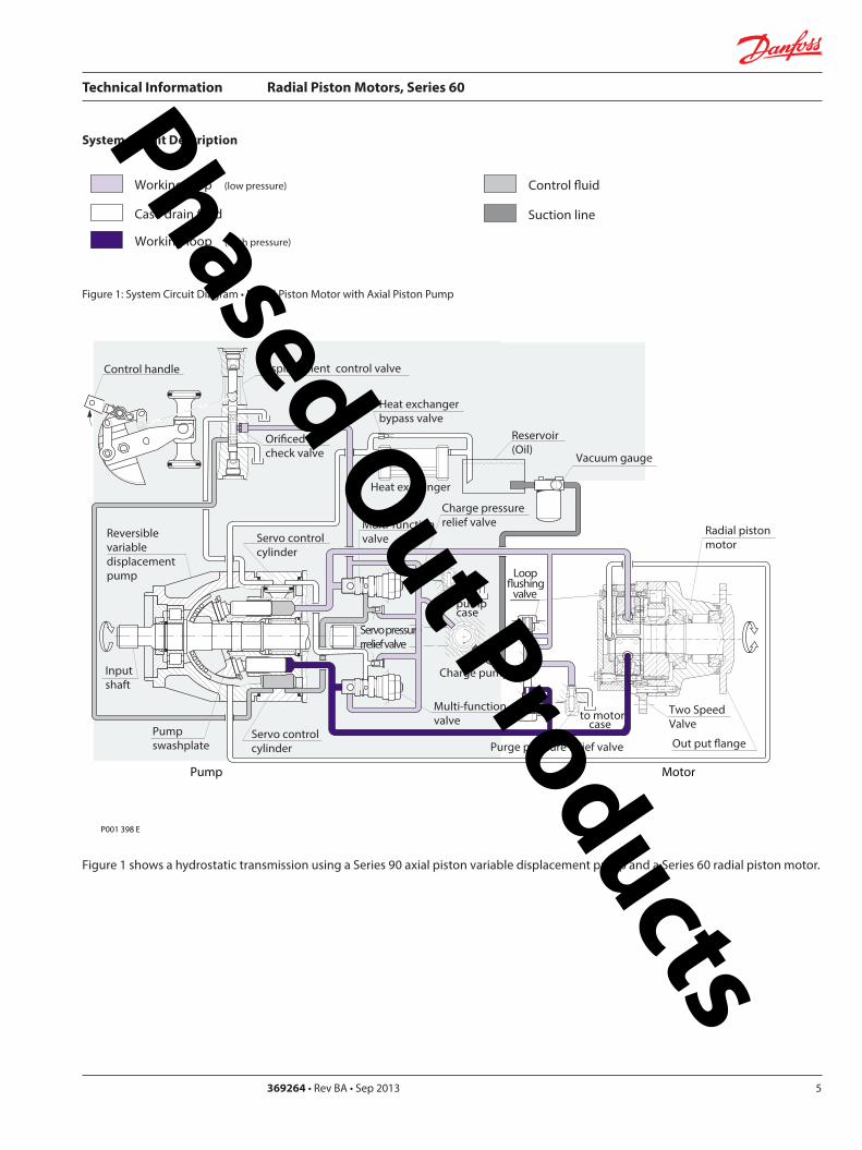
Technical Information Radial Piston Motors Series 60
5369264 bull Rev BA bull Sep 20136
Sectional View
Figure 2 Series 60 Radial Piston Motor
AAPiston
Distributor
Frame Mounting Face
BearingRim Mounting Face
P001 396
Loop ushingvalve(Option No loopushing)
Two-SpeedValve
P001 397
Section A - A
Phased Out Products
Technical Information Radial Piston Motors Series 60
369264 bull Rev BA bull Sep 2013 7
Type Designation and Order Code
6 0
Frame Size
Displacement per RevSize0470 = 470 cm3 (287 in3)0780 = 780 cm3 (476 in3)1048 = 1048cm3 (639 in3)1750 =1 750cm3 (1068 in3)
N N NNN N N
Displacement-OptionD090 = 090D100 = 100D110 = 110D120 = 120D130 = 130
Data sheetNN = Std
= Standard = optional
Brake OptionsN = None (Single Speed)K = None (Two Speed)P = With Brake
Control OptionsN N = None
Port StyleT = SAE O Ring Boss (0470 0780)S = SAE FlangeJ518cC 62 (1048 1750)
Brake TypeN = Without brake1 = Type 1 (60)3 = Type 3 (90)
Distributor Cover Options1W = Single Speed Wheel- Flange Motor2W = Two Speed Wheel- Flange Motor1S = Single Speed Shaft Motor2S = Two Speed Shaft Motor
Special HardwareN N N = NoneN N S = Speed Sensor
Pref RotationN = None Single-SpdR =CW Two-SpeedL =CCW Two-Speed
Charge Pressure00 = None14 = 14 bar18 = 18 bar20 = 20 bar24 = 24 bar
Motor DesignM =Single SpeedV =Two Speed
Shaft CongurationS1S = Shaft motor SAE-SplineW1W = Wheel MotorW2C = Flange Motor
Loop FlushingL = WithN = None
Series orProduct60=Series 60Radial PistonMotor
Phased Out Products
Technical Information Radial Piston Motors Series 60
5369264 bull Rev BA bull Sep 20138
Notes Phased Out Products
Technical Information Radial Piston Motors Series 60
369264 bull Rev BA bull Sep 2013 9
Circuit Diagram and Nomenclature
Radial Piston Motor
Figure 3 Circuit diagram middot Radial Piston Motor
PortsA B = Main pessure linesL1 L2 = Drain lines
DesignRadial piston cam ring motor in single and two speed version
Type of MountingFlange mounting with pilot
Pipe ConnectionsMain pressure ports SAE straight thread O-ring boss Size 0470 and 0780 SAE flange Code 62 Size 1048 and 1750 Other ports SAE straight thread O-ring boss Refer to ldquoDimensionsrdquo section for port sizes
Direction of Rotation Clockwise and counter-clockwise (bi-directional)
Installation PositionInstallation position as required The housing must always be filled with hydraulic fluid
Flow DirectionRefer to ldquoDimensions sectionrdquo
Hydraulic Parameters
System Pressure Range Port A and BMax pressure 480 bar (7000 psi)
Min pressure [450 bar (6500 psi) for 130 Option] See Diagram Page 11 Fig 5
Case PressureMax Continuous 3 bar (44 psi) Max intermittent 14 bar (200 psi) (cold start)
Pilot Pressure Two Speed OptionFor minimum displacement signal pressure to displacement change port ldquox1rdquo Min pressure 10 bar (145 psi) (above case pressure) Max pressure 50 bar (725 psi)
Hydraulic FluidRefer to Publication BLN-9887 or 697581 Refer to ATI-E 9101 for information relating to biodegradeable fluids
Temperature Rangeϑ min = -20 degC (-4 degF) intermittent cold startϑ nominal = 80 degC (175 degF) continuousϑ max = 85 degC (188 degF) intermittent 1)
Hydraulic fluid viscosity must be as shown below1) at the hottest point normally the case drain line
Fluid Viscosity Limitsν min = 9 mm2s ( 55 SUS) continuous ν max= 1600 mm2s (7400 SUS) intermittent cold start
FiltrationRequired cleanliness level ISO 4406 Code 1813 or betterRefer to publication BLN-9887 or 697581 and ATI-E 9201
Technical Specificatons - Radial Piston Motors Cam Ring Design
P001 390
B
L1
A
L2
Phased Out Products
Technical Information Radial Piston Motors Series 60
5369264 bull Rev BA bull Sep 201310
Technical Data ndash Radial Piston Motors
Table 1
Determination of Nominal Motor Size (Metric System)
Vg middot nInput flow Qe = mdashmdashmdashmdash lmin 1000 middot ηv
Vg middot Dp middot ηmhOutput torque Me = mdashmdashmdashmdashmdash Nm 20 middot π
Vg = Motor displacement per rev cm3 Dp = pHD - pND bar ηv = Motor volumetric efficiency ηmh = Motor mechanical ndash hydraulic (Torque) efficiency
Me middot n Qe middot Dp middot ηt Output power Pe = mdashmdashmdashmdash = mdashmdashmdashmdashmdash kW 9950 600
Qe middot 1000 middot ηvSpeed n = mdashmdashmdashmdashmdash min-1
Vg
ηv = Motor overall efficiency pHD = High pessure barpND = Low pressure bar
Frame Size
(Dimension) 0470 0780Displacement - Option 90 100 100 110 120 130
Displacement Vg cm 3 423 470 517 564 611 702 780 858 936 1014
in3
Vg 05 cm 3 212 235 259 282 306 351 390 429 468 507in3
Rated Speed n min -1 (RPM) 235 200
Output Speed max n min -1 (RPM) 310 295 280 270 260 260 250 240 230 220Theoretical Torque at Vg Nm bar 673 748 823 898 972 1117 1241 1366 1490 1614
lbfbullin1000 psi 4117 4576 5035 5494 5946 6833 7592 8357 9115 9874
Vg 05 Nm bar 337 374 411 449 486 559 621 683 745 807lbfbullin1000 psi 2062 2288 2514 2747 2973 3420 3799 4178 4558 4937
Max Flow at Vg Q l min 131 138 145 152 159 183 195 206 215 223
galmin (US
Max Flow at Vg 05 Q l min 66 69 72 76 79 91 98 103 108 112
galmin (US
Output PowerSingle Speed at Vg kW 29 41
hp 39 55
Two Speed P kW 19 27pref Direction Vg 05 hp 25 36
Two Speed P kW 14 20
not pref Direction Vg 05 hp 19 27
Weight
Wheel Motor m kg 46 74
lb 101 163
Flange Motor m kg 42 71
lb 93 157
Shaft Motor m kg 49 72lb 108 159
P
110 120 130 90
259 287 315 344 373 428 476 524 571 619
173 183 191 201 210 241 257 272 284 294
129 143 158 172 187 214 238 262 285 309
346 366 382 402 420 482 515 544 568 589
Phased Out Products
Technical Information Radial Piston Motors Series 60
369264 bull Rev BA bull Sep 2013 11
Technical Data ndash Radial Piston Motors (cont)
Table 2
Determination of Nominal Motor Size (Inch System)
Vg middot nInput flow Qe = mdashmdashmdashmdash galmin US 231 middot ηv
Vg middot Dp middot ηmhOutput torque Me = mdashmdashmdashmdashmdash lbf in 24 middot π
Vg = Motor displacement per rev in3 Dp = pHD - pND psi ηv = Motor volumetric efficiency ηmh = Motor mechanical ndash hydraulic (Torque) efficiency
Me middot n Qe middot Dp middot ηt Output power Pe = mdashmdashmdashmdash = mdashmdashmdashmdashmdash HP 5252 1715
Qe middot 231 middot ηvSpeed n = mdashmdashmdashmdashmdash min-1
Vg
ηv = Motor overall efficiency pHD = High pessure psipND = Low pressure psi
Frame Size
(Dimension) 1048 1750Displacement - Option 90 100 110 120 130 100 110 120 130
Displacement Vg cm 3 943 1048 1153 1258 1362 1575 1750 1925 2100 2275in3 575 640 704 768 831 961 107 1175 1281 1388
Vg 05 cm3 472 524 576 629 681 788 875 963 1050 1138in3
Rated Speed n min -1 (RPM) 180 150
Output Speed max n min -1 (RPM) 240 230 215 210 200 200 195 185 175 170Theoretical Torque at Vg Nm bar 1501 167 1835 2002 2168 2507 2785 3064 3342 3621
lbfbullin1000 psi 9183 10217 11226 12248 13263 15337 17038 18745 20445 22152
Vg 05 Nm bar 750 834 918 1001 1084 1253 1393 1532 1671 1810lbfbullin1000 psi 4588 5102 5616 6124 6632 7665 8522 9372 10223 11073
Max Flow at Vg Q l min 226 241 248 264 272 315 341 356 368 387
galmin (US
Max Flow at Vg 05 Q l min 113 121 124 132 136 158 171 178 184 193
galmin (US
Output PowerSingle Speed at Vg P kW 50 70
hp 67 94
Two Speed P kW 33 47 pref Direction Vg 05 hp 44 63Two Speed P kW 25 35
not pref Direction Vg 05 hp 34 47
Weight
Wheel Motor m kg 99 149
lb 218 329
Flange Motor m kg 95 144
lb 209 318
Shaft Motor m kg 96 152lb 212 335
90
288 320 351 384 416 481 534 588 641 694
600 636 655 697 718 832 901 940 970 1021
299 318 327 349 359 416 450 470 485 511
Phased Out Products
Technical Information Radial Piston Motors Series 60
5369264 bull Rev BA bull Sep 201312
Speed RangeThe Rated Speed is the max speed recommended at max permitted operating power at which normal life can be expected All other operating conditions (eg fluid viscosity and temperature charge pressure) must be within recom-mended ranges
Maximum Speed is the max operating speed permitted and cannot be exceeded without reduction in the life of the product or risking immediate failure and loss of driveline power (which may create a safety hazard)
W Braking Warning The loss of hydrostatic driveline power in any mode (eg acceleration deceleration or neutral mode of operation) may cause a loss of braking capacity A braking system which is independent of the hydrostatic transmission must therefore be provided which is adequate to stop and hold the system should the condition develop
System Pressure RangeSystem pressure is a dominant operating variable affecting hydraulic unit life High pressure which results from high load reduces expected life in a manner similar to many mechanical assemblies such as engines and gearboxes The maximum pressure is the highest intermittent pres-sure allowed It is determined by the maximum machine load demand Maximum pressure is assumed to occur a small percentage of operating time usually less than 2 of the total Maximum pressure is normally the relief valve setting It is desirable to have a machine duty cycle with the percentage of time at various loads and speeds An appro-priate design pressure can be calculated by our application department from this information This method of selecting operating pressure is recommended whenever duty cycle information is available
Case PressureUnder normal operating conditions the maximum continu-ous case pressure must not exceed 3 bar (44 psi) Maximum allowable intermittent case pressure during cold start must no exceed 14 bar (200 psi)
Hydraulic FluidsUse only recommended hydraulic fluids in accordance to manual BLN-9887 697581 and ATI-E 9101 While fluids containing anti-wear additives are not necessary for the satisfactory performance of the series 60 units they are often required for associated equipment These fluids must possess good thermal and hydrolytic stability to prevent wear erosion and corrosion of internal compo-nents It is not permissible to mix hydraulic fluids Fire-resistant fluids are also suitable at modified
Temperature LimitsRefer to page 7 for maximum allowable temperatures for petroleum based fluids These temperature limits apply at the hottest point of the transmission which is normally the case drain Heat exchangers should be sized to keep the fluid within the limits
Loop FlushingSeries 60 motors incorporate an integral loop flushing valve Installations that require additional fluid to be removed from the main hydraulic circuit because of fluid cooling requirements or circuits requiring the removal of excessive contamination from the high pressure circuit can benefit from loop flushing Series 60 motors with an integral loop flushing valve also include a purge pressure relief valve The setting of the motor charge relief valve affects the function of the flushing circuit Higher motor purge relief settings reduce the loop flushing flow and increase the flow over the pump charge pressure relief valve when the circuit is operating Lower motor purge relief settings increase the loop flushing flow and may increase the motor case pressure when the circuit is operating An appropriate combination of pump and motor charge pressure settings should be maintained to insure the proper function of the loop flushing circuit Correct charge pressure must be maintained under all conditions of operation to maintain control performance in closed loop systems
Figure 4 Loop Flushing Valve
General Technical Specifications
P001 397
Phased Out Products
Technical Information Radial Piston Motors Series 60
369264 bull Rev BA bull Sep 2013 13
Figure 5 Minimum charge pressure (above Case Pressure) Single Speed and Two Speed MotorGeneral Technical Specifications (Continued)
Charge Pressure Requirements
Park BrakeBrake Description
The brake is of the multiple-plate type A belleville spring washer is acting against the piston pressing stationary and rotating discs against each other When the brake piston is pressurized the force on the piston overcomes the force of the belleville spring and releases the brake
Figure 6 Circuit Diagramm
To move the vehicle or machine without the availability of brake release pressure a mechanical release option is available The torque specified for this brake is only validated under static conditions
Figure 7 Brake section View
P001 420E
Two SpeedMotor
Single SpeedMotor
0 20 40 60 80 100
Output Speed max speed
0
2 (30)
4 (60)
6 (90)
8 (120)
10 (150)
12 (180)
14 (210)
16 (240)
Min
Pre
ssur
e ba
r (ps
i)
18 (270)
20 (300)
P001 439 P001 406
Table 3 Input Brakes
DimensionFrame Size
0470 0780 1048 1750
Brake Torque static permitted (Applies for petroleum based fluid)
Nm 2500 4200 5700 9600lbin 22 100 37 100 50 400 84 900
Brake release pressure above case pressure
bar 15 min 30 maxpsi 218 min 435 max
Phased Out Products
Technical Information Radial Piston Motors Series 60
5369264 bull Rev BA bull Sep 201314
Series 60 Motors run in freewheeling mode with almost no losses The necessary valving needs to be added into the circuit The schematic below shows a solution closed circuit operation
The following has to be provided y The high pressure ports of the motor are
connected to the tank y A low pressure is applied to the motor drain
port (Fig 8)which pushes the pistons into their cylinders (Fig9) disengaging them from the cam The necessary case pressure is shown on table 4
General Technical Specifications (Continued)
Freewheeling Option
Speed Pick-Up
Shock Load
Table 4 Max speeds in freewheeling condition
Case pressure 15 bar (22 psi)above ports A and B Dimension
Frame Size0470 0780 1048 1750
Freewheeling Output Speed max min-1 (RPM) 770 630 560 450
Figure 8 Circuit Diagramm Figure 9 Motor Section View Fig 10 Circuit DiagrammFreewheeling Option Freewheeling mode Two Speed Option
P001 440 P001 441 P001 449
B
L1
A
x1
L2
Two Speed OptionThe Two Speed Option is available on all motor sizes allowing increased application flexibility The integral displacement change valve selects half displacement When the displacement change port ldquox1rdquo (Fig 10) is connected to tank or motor case pressure maximum displacement is selected
When a signal pressure min 10 bar ( 145 psi) above case pressure [max 50 bar ( 725 psi)] is connected to ldquox1rdquo minimum displacement is selected Motor performance and life is optimal in the preferred direction of rotation (see Dimensions) The displacement should be changed while the motor is stationary This avoids sudden or unexpected speed changes and possible transmission damage
Series 60 Motors speed pick-up (Hall Effect Sensor) is especially designed for rough outdoor mobile or heavy industrial applications where speed monitoring revolution counting speed limit control or alarm function is required with no physical contact with the sensed motor shaft
Pin 1 Supply voltage = 45 to 16 V dc Supply current At 5 V -16 mA Pin 2 Not usedPin 3 Output digital open collector NPN Pin 4 Ground For installation and connector details see Fig 28 page 23
Table 5 Pulse Frequency
Motor Frame Size 0470 0780 1048 1750Pulses per revolution 78 92 101 121
Motors are designed for 20 g external accelleration
Phased Out Products
Technical Information Radial Piston Motors Series 60
369264 bull Rev BA bull Sep 2013 15
Figure 11 shows the volumetric mechanical and overall efficiencies of a typical Series 60 single and two speed motor at full displacement and system pressures of 200 bar (2900 psi) and 400 bar (5800 psi) with a fluid viscosity of 20 mm2s (98 SUS) at a temperature of 60 degC (140 degF)
Figure 12 shows the overall efficiency of a typical Series 60 single and two speed motor at full displacement with system pressure up to 480 bar (7000 psi) with a fluid viscosity of 20mm2s ( 98 SUS) at a temperature of 60 degC (140 degF)
General Technical Specifications (Continued)
Efficiency Graphs and Maps
Figure 11 Volumetric Mechanical and Overall Efficiency
Figure 12 Overall Efficiency
P001 392ESpeed of rated speed
Eci
ency
0 25 50 75 100
74
76
78
80
82
84
86
88
90
92
94
96
98
100
ηt = 400 bar (5800 psi)
Overall Eciencyηt = 200 bar (2900 psi)
Volumetric Eciencyηv = 200 bar (2900 psi)
ηm= 400 bar (5800 psi)
ηv = 400 bar (5800 psi)
Mechanical Eciency ηm = 200 bar (2900 psi)
Speed of rated speed
0
Syst
em p
ress
ure
∆p
bar (
psi)
25 75 100
85
8992
94
95
80
500
480 (7000)
300 (4350)
200 (2900)
100 (1450)
400 (5800)
500 (7250)
P001 394E
Phased Out Products
Technical Information Radial Piston Motors Series 60
5369264 bull Rev BA bull Sep 201316
Figure 13 shows the volumetric mechanical and overall efficiencies of a typical Series 60 single and two speed motor at half displacement in the preferred direction and system pressures of 200 bar (2900 psi) and 400 bar (5800 psi) with a fluid viscosity of 20 mm2s ( 98 SUS) at a temperature of 60deg C (140deg F)
Figure 14 shows the overall efficiency of a typical Series 60 single and two speed motor at half displacement in the preferred direction and system pressure up to 480 bar (7000) psi) with a fluid viscosity of 20 mm2s ( 98 SUS) at a temperature of 60 degC (140 deg F)
General Technical Specifications (Continued)
Efficiency Graphs and Maps
Figure 13 Volumetric Mechanical and Overall Efficiency at half displacement in the preferred direction
Figure 14 Overall Efficiency at half displacement in the preferred direction
P001 393 E
Speed of rated speed
Eci
ency
ηm= 200 bar (2900 psi)
0 25 50 75 100
65
70
75
80
85
90
95
100Volumetric Eciency ηv = 200 bar (2900 psi)
Mech Eciencyηm= 400 bar (5800 psi)
Overall Eciency ηt = 200 bar (2900 psi)
ηv = 400 bar (5800 psi)
ηt = 400 bar (5800 psi)
0 25 50 75
Speed of rated speed
78 84
88
9091
92
Syst
em p
ress
ure
∆p
bar (
psi)
500 (7250)
300 (4350)
200 (2900 )
100 (1450)
0
400 (5800)
480 (7000)
100P001 402 E
Phased Out Products
Technical Information Radial Piston Motors Series 60
369264 bull Rev BA bull Sep 2013 17
Dimensions60M0470 60V0470
Figure 15 Wheel Motor 60M0470 Single Speed VersionWheel Motor 60V0470 Two Speed Version
View X
TwoSpeed
L1A
B
300
(11
8)
81(319)
2020
2010
R 175R (069)
Purge Pressure Relief Valve
Case Drain Ports L1 + L2
degdeg
degdeg
Loop Flushing Shuttle Valve
L2
x1
265
(10
43)
175 +025-010
(689) +01 -004
30deg
for Speed Pick Up9 16-18UNF-2Binclined 15 degoptional
oslash05 Aoslash(02 ) A
80(315)
77(303)
94(37)
225(886)
P001 426E
oslash92
8-0
2(D
ia 3
65
-01
)
DisplacementChange Port X1716-20UNF-2B
Main Ports A + B 1 116-12UNF-2B
Studs 10x36 deg M14x15
13(51)
36(142)
6(24)
oslash14
0(D
ia 5
51)
oslash17
5(D
ia 6
89)
oslash22
3(D
ia 8
78)
Case Drain Port L1 34-16UNF-2B10deg inclined
64( L1L2 )(252)
54 (213)
7(28)
425 (167)
MountingSurface for Brake (Option)
Purge Pressure Relief Valve
312(123)
15 (59)
180(709)
oslash22
4-0
2(D
ia 8
82
-01
)
80 (32
)
67 (264)
90 (35
4)
82 (323)
505(199)
96(38)
TwoSpeed
A
10(4)
X
Single Speed MotorPortFlow
Rotation in outLH(CCW) B ARH (CW) A B
Two Speed MotorPref Rotation Right
Rotation in outLH(CCW) A BRH (CW) B A
Two Speed MotorPref Rotation Left
Rotation in outLH(CCW) B ARH (CW) A B
Rotation Radial Load Curve
P001 425E
Distance from Hub Mounting Face mm (in)
-4 -2 0 2 6-6-79 4 8 99
-200 -100 -50 0 50 100 150 200-150 250
Max
Rad
ial L
oad
kN (
lb)
0
20
40
60
4500
9000
0
13 500
18 000 80
Dynamic loadat DierentialPressure250 bar (3600 psi)
Phased Out Products
Technical Information Radial Piston Motors Series 60
5369264 bull Rev BA bull Sep 201318
Dimensions60M0470 60V0470
Figure 16 Flange Motor 60M0470 Single Speed VersionFlange Motor 60V0470 Two Speed Version
Single Speed MotorPortFlow
Rotation in outLH(CCW) B ARH (CW) A B
Two Speed MotorPref Rotation Right
Rotation in outLH(CCW) A BRH (CW) B A
Two Speed MotorPref Rotation Left
Rotation in outLH(CCW) B ARH (CW) A B
View X
X
P001 427E
TwoSpeed
L1A
B
300
(11
8)
81(319)
2020
2010
R 175R (069)
Purge Pressure Relief Valve
Case Drain Ports L1 + L2
degdeg
degdeg
Loop Flushing Shuttle Valve
L2
x1
265
(10
43)
175 +025-010
(689) +01 -004
30deg
for Speed Pick Up9 16-18UNF-2Binclined 15 degoptional
oslash05 Aoslash(02 ) A
80(315)
77(303)
94(37)
225(886)
P001 426E
Rotation Radial Load Curve
Dynamic loadat DierentialPressure250 bar (3600 psi)
Distance from Hub Mounting Face mm (in)
-4 -2 0 2 6-6-79 4 8 99
-200 -100 -50 0 50 100 150 200-150 250
Max
Rad
ial L
oad
kN (
lb)
0
20
40
60
4500
9000
13 500
0
oslash92
8-0
2(D
ia 3
65
-01
)
DisplacementChange Port X1716-20UNF-2B
Main Ports A + B 1 116-12UNF-2B25deg inclined
Studs 5x72 deg M14x15
12(47)
37(146)
6(24)
oslash14
0(D
ia 5
51)
oslash17
5(D
ia 6
89)
oslash22
3(D
ia 8
78)
Case Drain Ports L1 34-16UNF-2B10deg inclined
64( L1L2 )(252)
25 (98)
7(28)
425 (167)
MountingSurface for Brake (Option)
Purge Pressure Relief Valve
280(110)
15 (59)147(579)
oslash22
4-0
2(D
ia 8
82
-01
)
80 (32
)
67 (264)90 (3
54)
82 (323)
505(199)
96(38)
Two Speed
A
10(4)
Phased Out Products
Technical Information Radial Piston Motors Series 60
369264 bull Rev BA bull Sep 2013 19
Dimensions60M0470 60V0470
Figure 17 Shaft Motor 60M0470 Single Speed VersionShaft Motor 60V0470 Two Speed Version
Single Speed MotorPortFlow
Rotation in outLH(CCW) B ARH (CW) A B
Two Speed MotorPref Rotation Right
Rotation in outLH(CCW) A BRH (CW) B A
Two Speed MotorPref Rotation Left
Rotation in outLH(CCW) B ARH (CW) A B
View X
P001 428E
TwoSpeed
L1A
B
300
(11
8)
81(319)
2020
2010
R 175R (069)
Purge Pressure Relief Valve
Case Drain Ports L1 + L2
degdeg
degdeg
Loop Flushing Shuttle Valve
L2
x1
265
(10
43)
175 +025-010
(689) +01 -004
30deg
for Speed Pick Up9 16-18UNF-2Binclined 15 degoptional
oslash05 Aoslash(02 ) A
80(315)
77(303)
94(37)
225(886)
X
P001 426E
Rotation
Max Radial Load
DisplacementChange Port X1716-20UNF-2B
Main Ports A + B 1 116-12UNF-2B25deg inclined
Case Drain Port L1 34-16UNF-2B10deg inclined
395 (156)
18 ( L1L2 )(7)
MountingSurface for Brake (Option)
Purge Pressure Relief Valve
oslash22
3(D
ia 8
78)
80 (32
)
15 (59)
90 (35
4)
315 (124)
Two Speed
23(91)10 (39)
oslash20
0-0
07
(Dia
787
4-0
03)
312(123)
203 (799)
39(154)
54 (213)
38-
16U
NC
x15
(59)
full
THD
254
(10
)
34(134)
R25 +02(R10 +01 )
87 (343)
47(185)
Shaft Spline Data5 ssalC a1129B ISNA Spline standard
Spline Fit Pitch D
03 elgnA erusserPNo of teethSplineMajor Dia
A
-50 -40 -30 -20 -10 0
-2 -1
50
60
30
40
20
0
10
Allo
wab
lera
dial
Loa
d kN
(lb
)
Distance from Shaftshoulder mm (in)
0
2250
6750
9000
11250
4500
13500
0
Dynamic loadat ∆p = 250 bar (3600 psi)
Flat Root Side Fit4863 (1916)
231224508 (20)
Phased Out Products
Technical Information Radial Piston Motors Series 60
5369264 bull Rev BA bull Sep 201320
Dimensions60M0780 60V780
Figure 18 Wheel Motor 60M0780 Single Speed VersionWheel Motor 60V0780 TwoSpeed Version
Single Speed MotorPortFlow
Rotation in outLH(CCW) B ARH (CW) A B
Two Speed MotorPref Rotation Right
Rotation in outLH(CCW) A BRH (CW) B A
Two Speed MotorPref Rotation Left
Rotation in outLH(CCW) B ARH (CW) A B
20
40
60
80
0
4500
9000
13 500
18 000
Max
Rad
ial L
oad
kN (
lb)
Dynamic load atDierential Pressure250 bar (3600 psi)
Distance from Hub Mounting Face mm (in)
-200 -150 -100 -50 0 50 100 150 200 250
-79 -6 -4 -2 0 2 4 6 8 98
oslash16
08
-02
(Dia
63
3 -0
1)
DisplacementChange Port X1716-20UNF-2B
Main Ports A + B 1 116-12UNF-2B25deg inclined
Studs 6x60 deg M18x15
15(6)
36(142)
8(31)
oslash20
5(D
ia 8
1)
oslash24
7(D
ia 9
7)
oslash26
6(D
ia 1
05)
Case Drain Port L134-16UNF-2B10deg inclined
70( L1L2 ) (276)
58 (228)
7(28)
44 (173)
MountingSurface for Brake (Option)
Purge Pressure Relief Valve
334(123)
17 (7)
195(768)
oslash25
3-0
2(D
ia 9
96
-01
)96 (38
)
72 (283)
106
(42
)
88 (35)
51(201)
104(409)
A
TwoSpeed
17(7)
View X
for Speed Pick Up9 16-18UNF-2Binclined 15 degoptional
L2L1A
B
335
(13
2)
267(1051)
R 175R (069)
Purge Pressure Relief Valve
Case Drain Ports L1 + L2
Loop Flushing Shuttle Valve
x1
TwoSpeed
300
(11
81)
175 +025-010
(689) +01 -004
oslash05 Aoslash(02 ) A
30deg
15deg15deg
15deg15deg
96(38)
93(37)
91(36)
109(43)
P001 435E
P001 436E
Rotation Radial Load Curve
X
Phased Out Products
Technical Information Radial Piston Motors Series 60
369264 bull Rev BA bull Sep 2013 21
Dimensions60M0780 60 V780
Figure 19 Flange Motor 60M0780 Single Speed VersionFlange Motor 60V0780 Two Speed Version
Single Speed MotorPortFlow
Rotation in outLH(CCW) B ARH (CW) A B
Two Speed MotorPref Rotation Right
Rotation in outLH(CCW) A BRH (CW) B A
Two Speed MotorPref Rotation Left
Rotation in outLH(CCW) B ARH (CW) A B
View X
X
Max
Rad
ial L
oad
kN (
lb)
0
20
40
60
4500
9000
13 500
0
8018 000
Distance from Hub Mounting Face mm (in)
-4 -2 0 2 6-6-79 4 8 99
-200 -100 -50 0 50 100 150 200-150 250
Dynamic loadat DierentialPressure250 bar (3600 psi)
72 (283)
DisplacementChange Port X1716-20UNF-2B
Main Ports A + B 1 116-12UNF-2B25deg inclined
Case Drain Port L134-16UNF-2B
10deg inclined
70( L1L2 )(276)
27 (106)
7(28)
44 (173)
MountingSurface for Brake (Option)
304(119)
17 (7)
25(10)
oslash25
3-0
2(D
ia 9
96
-01
)
96 (38
)
106
(42
)
88 (35)
51(201)
104(409)
Two Speed
A
oslash16
08
-02
(Dia
63
3 -0
1)
Studs 6x60 deg M18x15
15(6)
36(142)
7(3)
oslash20
5(D
ia 8
1)
oslash24
7(D
ia 9
7)
oslash26
6(D
ia 1
05)
Purge Pressure Relief Valve
164(65)
for Speed Pick Up9 16-18UNF-2Binclined 15 degoptional
L2L1A
B
335
(13
2)
267(1051)
R 175R (069)
Purge Pressure Relief Valve
Case Drain Ports L1 + L2
Loop Flushing Shuttle Valve
x1
TwoSpeed
300
(11
81)
175 +025-010
(689) +01 -004
oslash05 Aoslash(02 ) A
30deg
15deg15deg
15deg15deg
96(38)
93(37)
91(36)
109(43)
P001 436E
P001 437E
Rotation Radial Load Curve
Phased Out Products
Technical Information Radial Piston Motors Series 60
5369264 bull Rev BA bull Sep 201322
Dimensions60M0780 60V780
Figure 20 Shaft Motor 60M0780 Single Speed VersionShaft Motor 60V0780 Two Speed Version
Single Speed MotorPortFlow
Rotation in outLH(CCW) B ARH (CW) A B
Two Speed MotorPref Rotation Right
Rotation in outLH(CCW) A BRH (CW) B A
Two Speed MotorPref Rotation Left
Rotation in outLH(CCW) B ARH (CW) A B
View X
for Speed Pick Up9 16-18UNF-2Binclined 15 degoptional
L2L1A
B
335
(13
2)
267(1051)
R 175R (069)
Purge Pressure Relief Valve
Case Drain Ports L1 + L2
Loop Flushing Shuttle Valve
x1
TwoSpeed
300
(11
81)
175 +025-010
(689) +01 -004
oslash05 Aoslash(02 ) A
30deg
15deg15deg
15deg15deg
96(38)
93(37)
91(36)
109(43)
X
P001 436E
Rotation
Max Radial Load
DisplacementChange Port X1716-20UNF-2B
Main Ports A + B1 116-12UNF-2B25deg inclined
Case Drain Port L134-16UNF-2B10deg inclined
44 (173)
18 ( L1L2 ) (71)
MountingSurface for Brake (Option)
Purge Pressure Relief Valve
oslash26
7(D
ia 1
051
)96 (38
)
16 (63)
106
(42
)
37 (146)
Two Speed
25(98)16 (63)
oslash22
4-0
15
(Dia
88
19-0
06)
343(1350)
215 (846)
40(157)
70 (276)
38-
16 U
NC
x15
(59)
full
THD
381
(15
)
46(181)
R3 +02(R12 +01 )
97 (382)
54(213)
A
-100 -80 -60 -40 -20 0
-4 -2
100
60
80
40
0
20
Allo
wab
lera
dial
Loa
d kN
(lb)
Distance from Shaftshoulder mm (in)
0
9000
13500
4500
18000
0
22500
P001 438E
Dynamic load at∆p = 250 bar (3600 psi)
Shaft Spline Data5 ssalC a1129B ISNA Spline standard
Spline Fit Pitch D
03 elgnA erusserPNo of teethSplineMajor Dia
Flat Root Side Fit635 (25)
208166667 (2625)
Phased Out Products
Technical Information Radial Piston Motors Series 60
369264 bull Rev BA bull Sep 2013 23
Dimensions60M1048 60V1048
Figure 21 Wheel Motor 60M1048 Single Speed VersionWheel Motor 60V0470 Two Speed Version
Single Speed MotorPortFlow
Rotation in outLH(CCW) B ARH (CW) A B
Two Speed MotorPref Rotation Right
Rotation in outLH(CCW) A BRH (CW) B A
Two Speed MotorPref Rotation Left
Rotation in outLH(CCW) B ARH (CW) A B
View X
P001 414E
X
P001 415E
295(1161)
x110
degdeg
L1A
B
R 20 R (079)
108(425)
108(425)
Purge Pressure Relief Valve Loop Flushing Shuttle Valve
L2
TwoSpeed37
5 (1
476
)
2020
20
Case Drain Ports L1 + L2
degdeg
335
(13
19)
225 +025-010
(89) +01 -004
30deg
for Speed Pick Up9 16-18UNF-2Binclined 15 degoptional
oslash075oslash(03 )
AA
118(465)
Rotation Radial Load Curve
20
40
60
80
100
0
4500
9000
13 500
18 000
22 500
Max
Rad
ial L
oad
kN (
lb)
Distance from Hub Mounting Face mm (in)
-200 -150 -100 -50 0 50 100 150 200 250
-79 -6 -4 -2 0 2 4 6 8 98
Dynamic load atDierentialPressure250 bar (3600 psi)
Studs 5x72 deg M22x15
Case Drain Ports L1 + L2 34-16UNF-2B
66( L2 ) (260)
565(222)
Main Ports A + B 075-Code 62Split Flange Boss per SAE J 51838-16UNC-2B 22 (088) min full thread depth
8 (31)
48 (189)
MountingSurface for Brake (Option)
16(63)
47(185)
Purge Pressure Relief Valve
112(441)
379(1492)
19 (75)
220(866)
8 (31)
oslash17
58
-02
(Dia
69
2 -0
1)
oslash22
5(D
ia 8
86)
280
(Dia
11
02)oslash
292
(Dia
115
0)
508
(20
0)
285
-02
(11
22-0
1)
96 (37
8)
DisplacementChange Port X1716-20UNF-2B
79 (31)
115
(45
3)
Two Speed
96 (378)
238(94)
81( L1 )(319)
24(9)
A
Phased Out Products
Technical Information Radial Piston Motors Series 60
5369264 bull Rev BA bull Sep 201324
Dimensions60M1048 60V1048
Figure 22 Flange Motor 60M1048 Single Speed VersionFlange Motor 60V1048 Two Speed Version
Single Speed MotorPortFlow
Rotation in outLH(CCW) B ARH (CW) A B
Two Speed MotorPref Rotation Right
Rotation in outLH(CCW) A BRH (CW) B A
Two Speed MotorPref Rotation Left
Rotation in outLH(CCW) B ARH (CW) A B
View X
X
295(1161)
x1
10deg
deg
L1A
B
R 20 R (079)
108(425)
108(425)
Purge Pressure Relief Valve Loop Flushing Shuttle Valve
L2
TwoSpeed37
5 (1
476
)
2020
20
Case Drain Ports L1 + L2
degdeg
335
(13
19)
225 +025-010
(89) +01 -004
30deg
for Speed Pick Up9 16-18UNF-2Binclined 15 degoptional
oslash075oslash(03 )
AA
118(465)
Dynamic loadat DierentialPressure250 bar (3600 psi)
Max
Rad
ial L
oad
kN (
lb)
0
20
40
60
4500
9000
13 500
0
Distance from Hub Mounting Face mm (in)
-4 -2 0 2 6-6-79 4 8 99
-200 -100 -50 0 50 100 150 200-150 250
Studs 6x60 deg M18x15
Case Drain Ports L1 + L2 34-16UNF-2B
66( L2 ) (26)
255(100)
Main Ports A + B 075-Code 62Split Flange Boss per SAE J 51838-16UNC-2B 22 (088) min full thread depth
8(31)
48 (189)
MountingSurface for Brake (Option)
15(59)
36(142)
Purge Pressure Relief Valve
112(441)
322(127)
19 (75)
1745(687)
6(24)
oslash16
08
-02
(Dia
63
3 -0
1)
oslash20
5 (D
ia 8
07)
250
(Dia
98
4)
oslash29
2(D
ia11
50)
508
(20
)
285
-02
(11
22-0
1)
96 (37
8)
DisplacementChange Port X1716-20UNF-2B
79 (311)11
5 (4
53)
Two Speed
96 (378)
238(94)
81( L1 )(319)
A
255 (10)
P001 415E
Rotation Radial Load Curve
P001 416E
Phased Out Products
Technical Information Radial Piston Motors Series 60
369264 bull Rev BA bull Sep 2013 25
Dimensions60M1048 60V1048
Figure 23 Shaft Motor 60M1048 Single Speed VersionShaft Motor 60M1048 Two Speed Version
Single Speed MotorPortFlow
Rotation in outLH(CCW) B ARH (CW) A B
Two Speed MotorPref Rotation Right
Rotation in outLH(CCW) A BRH (CW) B A
Two Speed MotorPref Rotation Left
Rotation in outLH(CCW) B ARH (CW) A B
View X
295(1161)
x110
degdeg
L1A
B
R 20 R (079)
108(425)
108(425)
Purge Pressure Relief Valve Loop Flushing Shuttle Valve
L2
TwoSpeed37
5 (1
476
)
2020
20
Case Drain Ports L1 + L2
degdeg
335
(13
19)
225 +025-010
(89) +01 -004
30deg
for Speed Pick Up9 16-18UNF-2Binclined 15 degoptional
oslash075oslash(03 )
AA
118(465)
P001 415E
Rotation
Max Radial Load
X
73 ( L1 )(287)
28(110)13 (51)
oslash28
0-0
15
(Dia
110
24-0
06)
372(146)
2325 (915)
50 (197)
70 (276)
38-
16U
NC
15 (
59) f
ull T
HD
381
(15
)
46(181)
123 (484)
R 3 +02(R12 +01 )
515 (203)
Main Ports A + B 075-Code 62Split Flange Boss per SAE J 51838-16UNC-2B22 (088) min full thread depth
Case Drain Ports L1+L234-16UNF-2B
40 (157)
MountingSurface for Brake (Option)
104(41)
238(94)
508
(20
0)
oslash29
2(D
ia11
5)96 (37
8)
DisplacementChange Port X1716-20UNF-2B
17(67)
115
(45
3)
Two Speed
58( L2 )(228)
PurgePressureRelief ValveA
-100 -80 -60 -40 -20 0
-4 -2
120
60
80
40
0
20
Allo
wab
lera
dial
Loa
d kN
(lb)
Distance from Shaftshoulder mm (in)
0
9000
13500
4500
18000
0
22500 10027000
P001 417E
Dynamic load at ∆p = 250 bar (3600 psi)
Shaft Spline Data5 ssalC a1129B ISNA Spline standard
Spline Fit Pitch Dia
03 elgnA erusserPNo of teethSplineMajor Dia
Flat Root Side Fit73025 (30)
23816762 (30)
Phased Out Products
Technical Information Radial Piston Motors Series 60
5369264 bull Rev BA bull Sep 201326
Dimensions60M1750 60V1750
Figure 24 Wheel Motor 60M1750 Single Speed VersionWheel Motor 60V1750 Two Speed Version
Single Speed MotorPortFlow
Rotation in outLH(CCW) B ARH (CW) A B
Two Speed MotorPref Rotation Right
Rotation in outLH(CCW) A BRH (CW) B A
Two Speed MotorPref Rotation Left
Rotation in outLH(CCW) B ARH (CW) A B
View X
X
Rotation Radial Load Curve
P001 430E
P001 429E
L2L1A
B
425
(16
73)
Purge Pressure Relief Valve
Case Drain Ports L1 + L2
Loop Flushing Shuttle Valve
x1
Two Speed
385
(15
16)
225 +025-010
(89) +01 -004
oslash075 Aoslash(03 ) A
30deg
for Speed Pick Up9 16-18UNF-2Binclined 15 degoptional
15deg15deg
15deg15deg
350(1378)
R 20 R (079)
124(488)
124(488)
138(543)
Dynamic load atDierentialPressure250 bar (3600 psi)
(in)Distance from Hub Mounting Face mm
-200 -150 -100 -50 0 50 100 150 200 250
-79 -6 -4 -2 0 2 4 6 8 98
Max
Rad
ial L
oad
kN (
lb)
20
40
140
160
60
80
100
120
180
0
4500
9000
13 500
27 000
36 000
18 000
22 500
31 500
40 500
0
Studs 10x36 deg M22x15
Case Drain Ports L1 + L2 78-14UNF-2B
69(272)
Main Ports A + B 100-Code 62Split Flange Boss per SAE J 518716-14UNC-2B 27 (106) min full thread depth
11(43)
66 (2598)
MountingSurface for Brake (Option)
16(63)
47(185)
Purge Pressure Relief Valve
132(520)
433(1705)
225 (886)
254(100)
8 (31)
oslash17
58
-02
(Dia
69
2 -0
1)
oslash22
5(D
ia 8
86)
280
(Dia
11
02)oslash
350
(Dia
137
8)
571
5(2
25)
oslash33
0-0
2(D
ia12
992
-008
)
115
(45
28)
DisplacementChange Port X1716-20UNF-2B
99 (390)
141
(55
5)
Two Speed
116 (4567)
2776(1093)
96( L1L2 )(378)
20(0787)
A
Phased Out Products
Technical Information Radial Piston Motors Series 60
369264 bull Rev BA bull Sep 2013 27
Dimensions60M1750 60V1750
Figure 25 Flange Motor 60M1750 Single Speed VersionFlange Motor 60V1750 Two Speed Version
Single Speed MotorPortFlow
Rotation in outLH(CCW) B ARH (CW) A B
Two Speed MotorPref Rotation Right
Rotation in outLH(CCW) A BRH (CW) B A
Two Speed MotorPref Rotation Left
Rotation in outLH(CCW) B ARH (CW) A B
View X
X
P001 430E
Rotation Radial Load Curve
P001 431E
L2L1A
B
425
(16
73)
Purge Pressure Relief Valve
Case Drain Ports L1 + L2
Loop Flushing Shuttle Valve
x1
Two Speed
385
(15
16)
225 +025-010
(89) +01 -004
oslash075 Aoslash(03 ) A
30deg
for Speed Pick Up9 16-18UNF-2Binclined 15 degoptional
15deg15deg
15deg15deg
350(1378)
R 20 R (079)
124(488)
124(488)
138(543)
0
Dynamic loadat DierentialPressure250 bar (3600 psi)
Distance from Hub Mounting Face mm (in)
-6 -4 -2 0 2 64 8 99-79
-200 -100 -50 0 50 100 150 200-150 250
Max
Rad
ial L
oad
kN (
lb)
0
20
40
60
4500
9000
13 500
8018 000
10022 500
12027 000
14031 500
16036 000
18040 500
Studs 10x36 deg M22x15
Case Drain Ports L1 + L2 78-14UNF-2B
32(126)
Main Ports A + B 100-Code 62Split Flange Boss per SAE J 518716-14UNC-2B 27 (106) min full thread depth
11(43)
66 (2598)
MountingSurface for Brake (Option)
16(63)
47(185)
Purge Pressure Relief Valve
132(520)
389(1531)
225 (886)
210(1827)
8 (31)
oslash17
58
-02
(Dia
69
2 -0
1)
oslash22
5(D
ia 8
86)
280
(Dia
11
02)oslash
350
(Dia
137
8)
571
5(2
25)
oslash33
0-0
2(D
ia 1
299
2-0
08)
115
(45
28)
DisplacementChange Port X1716-20UNF-2B
99 (390)
141
(55
5)
Two Speed
116 (4567)
2776(1093)
96( L1 L2 )(378)
29 (114)
A
Phased Out Products
Technical Information Radial Piston Motors Series 60
5369264 bull Rev BA bull Sep 201328
Dimensions60M1750 60V1750
Figure 26 Shaft Motor 60M1750 Single Speed VersionShaft Motor 60V1750 Two Speed Version
Single Speed MotorPortFlow
Rotation in outLH(CCW) B ARH (CW) A B
Two Speed MotorPref Rotation Right
Rotation in outLH(CCW) A BRH (CW) B A
Two Speed MotorPref Rotation Left
Rotation in outLH(CCW) B ARH (CW) A B
View X
L2L1A
B
425
(16
73)
Purge Pressure Relief Valve
Case Drain Ports L1 + L2
Loop Flushing Shuttle Valve
x1
Two Speed
385
(15
16)
225 +025-010
(89) +01 -004
oslash075 Aoslash(03 ) A
30deg
for Speed Pick Up9 16-18UNF-2Binclined 15 degoptional
15deg15deg
15deg15deg
350(1378)
R 20 R (079)
124(488)
124(488)
138(543)
P001 430E
Rotation
X
Max Radial Load
Displacementchange Port X1716-20UNF-2B
24(94)15 (59)
oslash31
5-0
15
(Dia
124
02-0
06)
440(173)
2835 (1116)
48 (189)
90 (354)
12-
13 U
NC
X22
(86)
full
THD
381
(15
)
63(248)
141 (555)
R4 +02(R16 +01 )
97 (382)
Main Ports A + B 100-Code 62Split Flange Boss per SAE J 518716-14UNC-2B27 (106) min full thread depth
Case Drain Ports L1+L278-20UNF-2B
20 (079) ( L1+L2 )
50 (197)
MountingSurface for Brake (Option)Purge Pressure
Relief Valve
121 (48)
278(109)
572
(22
5)
oslash33
0(D
ia12
99)11
5 (4
53)
17 (67)
141
(55
5)
Two Speed
9 (35)
oslash35
0(D
ia13
78)
A
-100 -80 -60 -40 -20 0
-4 -2
200
100
150
0
50
Allo
wab
lera
dial
Loa
d kN
(lb)
Distance from Shaftshoulder mm (in)
0
22500
11250
33750
0
45000
P001 432E
Dynamic load at ∆p = 250 bar (3600 psi)
Shaft Spline Data5 ssalC a1129B ISNA Spline standard
Spline Fit Pitch Dia
03 elgnA erusserPNo of teethSplineMajor Dia
Flat Root Side Fit889 (35)
288169207 (3625)
Phased Out Products
Technical Information Radial Piston Motors Series 60
369264 bull Rev BA bull Sep 2013 29
NotesPhased Out Products
Technical Information Radial Piston Motors Series 60
5369264 bull Rev BA bull Sep 201330
DimensionsBrakes
Figure 27 Radial Piston Motor with Brake (0ptional)
P001 418E
Table 6 Brake Dimensions
Series Dimension
A B C
60M0470 23 (090) 74 (290) oslash212 (Dia 835)
60M0780 42 (165) 100 (394) oslash245 (Dia 965)
60M1048 30 (118) 90 (354) oslash280 (Dia 1102)
60M1750 38 (147) 107 (421) oslash320 (Dia 1260)
B
CX7
MountingFace
Mechanical BrakeRelease 1 to be used with Mech Brake Release 2
Mechanical BrakeRelease 2to be used with Mech Brake Release 1
A
Hydraulic BrakeRelease X7916-18UNF-2B
Mechanical BrakeRelease 1 to be used with Mech Brake Release 2
Mechanical BrakeRelease 2to be used with Mech Brake Release 1
TwoSpeed
X
View X
Phased Out Products
Technical Information Radial Piston Motors Series 60
369264 bull Rev BA bull Sep 2013 31
DimensionsSpeed Sensor
Figure 28 Radial Piston Motor with Speed Sensor (0ptional)
Section A - A (11)Speed Sensor
Connecto IdNoStraightRight angle
Connector is not supplied with the motorPlease order separatly using above Id No
Table 7 Speed Sensor Connector
Electrical details see page12
P001 444E
A
A
30deg 15 deg
31m
ax (1
22)
Pin 1Pin 2
Pin 3
Pin 4
Key Way
Wrench-Flats
Connector Insert
View Y
Y
127
(50)
500724500725
Phased Out Products
Comatrolwwwcomatrolcom
Schwarzmuumlller-Inverterwwwschwarzmueller-invertercom
Turolla wwwturollaocgcom
Valmovawwwvalmovacom
Hydro-Gear wwwhydro-gearcom
Daikin-Sauer-Danfosswwwdaikin-sauer-danfosscom
Danfoss Power Solutions is a global manufacturer and supplier of high-quality hydraulic and electronic components We specialize in providing state-of-the-art technology and solutions that excel in the harsh operating conditions of the mobile off -highway market Building on our extensive applications expertise we work closely with our customers to ensure exceptional performance for a broad range of off -highway vehicles
We help OEMs around the world speed up system development reduce costs and bring vehicles to market faster Danfoss ndash Your Strongest Partner in Mobile Hydraulics
Go to wwwpowersolutionsdanfosscom for further product information
Wherever off -highway vehicles are at work so is Danfoss
We off er expert worldwide support for our customers ensuring the best possible solutions for outstanding performance And with an extensive network of Global Service Partners we also provide comprehensive global service for all of our components
Please contact the Danfoss Power Solution representative nearest you
Products we off er
Bent Axis Motors
Closed Circuit Axial Piston Pumps and Motors
Displays
Electrohydraulic Power Steering
Electrohydraulics
Hydraulic Power Steering
Integrated Systems
Joysticks and Control Handles
Microcontrollers and Software
Open Circuit Axial Piston Pumps
Orbital Motors
PLUS+1reg GUIDE
Proportional Valves
Sensors
Steering
Transit Mixer Drives
Local address
Danfoss can accept no responsibility for possible errors in catalogues brochures and other printed material Danfoss reserves the right to alter its products without notice This also applies to products already on order provided that such alterations can be made without subsequential changes being necessary in specifications already agreedAll trademarks in this material are property of the respective companies Danfoss and the Danfoss logotype are trademarks of Danfoss AS All rights reserved
Danfoss Power Solutions22F Block C Yishan RdShanghai 200233 ChinaPhone +86 21 3418 5200
Danfoss Power Solutions GmbH amp Co OHGKrokamp 35D-24539 Neumuumlnster GermanyPhone +49 4321 871 0
Danfoss Power Solutions ApSNordborgvej 81DK-6430 Nordborg DenmarkPhone +45 7488 2222
Danfoss Power Solutions US Company2800 East 13th StreetAmes IA 50010 USAPhone +1 515 239 6000
369264 bull Rev BA bull Sep 2013 wwwdanfosscom copy Danfoss AS 2013-09
Phased Out Products
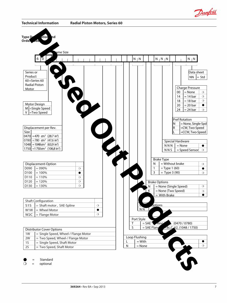
Technical Information Radial Piston Motors Series 60
369264 bull Rev BA bull Sep 2013 7
Type Designation and Order Code
6 0
Frame Size
Displacement per RevSize0470 = 470 cm3 (287 in3)0780 = 780 cm3 (476 in3)1048 = 1048cm3 (639 in3)1750 =1 750cm3 (1068 in3)
N N NNN N N
Displacement-OptionD090 = 090D100 = 100D110 = 110D120 = 120D130 = 130
Data sheetNN = Std
= Standard = optional
Brake OptionsN = None (Single Speed)K = None (Two Speed)P = With Brake
Control OptionsN N = None
Port StyleT = SAE O Ring Boss (0470 0780)S = SAE FlangeJ518cC 62 (1048 1750)
Brake TypeN = Without brake1 = Type 1 (60)3 = Type 3 (90)
Distributor Cover Options1W = Single Speed Wheel- Flange Motor2W = Two Speed Wheel- Flange Motor1S = Single Speed Shaft Motor2S = Two Speed Shaft Motor
Special HardwareN N N = NoneN N S = Speed Sensor
Pref RotationN = None Single-SpdR =CW Two-SpeedL =CCW Two-Speed
Charge Pressure00 = None14 = 14 bar18 = 18 bar20 = 20 bar24 = 24 bar
Motor DesignM =Single SpeedV =Two Speed
Shaft CongurationS1S = Shaft motor SAE-SplineW1W = Wheel MotorW2C = Flange Motor
Loop FlushingL = WithN = None
Series orProduct60=Series 60Radial PistonMotor
Phased Out Products
Technical Information Radial Piston Motors Series 60
5369264 bull Rev BA bull Sep 20138
Notes Phased Out Products
Technical Information Radial Piston Motors Series 60
369264 bull Rev BA bull Sep 2013 9
Circuit Diagram and Nomenclature
Radial Piston Motor
Figure 3 Circuit diagram middot Radial Piston Motor
PortsA B = Main pessure linesL1 L2 = Drain lines
DesignRadial piston cam ring motor in single and two speed version
Type of MountingFlange mounting with pilot
Pipe ConnectionsMain pressure ports SAE straight thread O-ring boss Size 0470 and 0780 SAE flange Code 62 Size 1048 and 1750 Other ports SAE straight thread O-ring boss Refer to ldquoDimensionsrdquo section for port sizes
Direction of Rotation Clockwise and counter-clockwise (bi-directional)
Installation PositionInstallation position as required The housing must always be filled with hydraulic fluid
Flow DirectionRefer to ldquoDimensions sectionrdquo
Hydraulic Parameters
System Pressure Range Port A and BMax pressure 480 bar (7000 psi)
Min pressure [450 bar (6500 psi) for 130 Option] See Diagram Page 11 Fig 5
Case PressureMax Continuous 3 bar (44 psi) Max intermittent 14 bar (200 psi) (cold start)
Pilot Pressure Two Speed OptionFor minimum displacement signal pressure to displacement change port ldquox1rdquo Min pressure 10 bar (145 psi) (above case pressure) Max pressure 50 bar (725 psi)
Hydraulic FluidRefer to Publication BLN-9887 or 697581 Refer to ATI-E 9101 for information relating to biodegradeable fluids
Temperature Rangeϑ min = -20 degC (-4 degF) intermittent cold startϑ nominal = 80 degC (175 degF) continuousϑ max = 85 degC (188 degF) intermittent 1)
Hydraulic fluid viscosity must be as shown below1) at the hottest point normally the case drain line
Fluid Viscosity Limitsν min = 9 mm2s ( 55 SUS) continuous ν max= 1600 mm2s (7400 SUS) intermittent cold start
FiltrationRequired cleanliness level ISO 4406 Code 1813 or betterRefer to publication BLN-9887 or 697581 and ATI-E 9201
Technical Specificatons - Radial Piston Motors Cam Ring Design
P001 390
B
L1
A
L2
Phased Out Products
Technical Information Radial Piston Motors Series 60
5369264 bull Rev BA bull Sep 201310
Technical Data ndash Radial Piston Motors
Table 1
Determination of Nominal Motor Size (Metric System)
Vg middot nInput flow Qe = mdashmdashmdashmdash lmin 1000 middot ηv
Vg middot Dp middot ηmhOutput torque Me = mdashmdashmdashmdashmdash Nm 20 middot π
Vg = Motor displacement per rev cm3 Dp = pHD - pND bar ηv = Motor volumetric efficiency ηmh = Motor mechanical ndash hydraulic (Torque) efficiency
Me middot n Qe middot Dp middot ηt Output power Pe = mdashmdashmdashmdash = mdashmdashmdashmdashmdash kW 9950 600
Qe middot 1000 middot ηvSpeed n = mdashmdashmdashmdashmdash min-1
Vg
ηv = Motor overall efficiency pHD = High pessure barpND = Low pressure bar
Frame Size
(Dimension) 0470 0780Displacement - Option 90 100 100 110 120 130
Displacement Vg cm 3 423 470 517 564 611 702 780 858 936 1014
in3
Vg 05 cm 3 212 235 259 282 306 351 390 429 468 507in3
Rated Speed n min -1 (RPM) 235 200
Output Speed max n min -1 (RPM) 310 295 280 270 260 260 250 240 230 220Theoretical Torque at Vg Nm bar 673 748 823 898 972 1117 1241 1366 1490 1614
lbfbullin1000 psi 4117 4576 5035 5494 5946 6833 7592 8357 9115 9874
Vg 05 Nm bar 337 374 411 449 486 559 621 683 745 807lbfbullin1000 psi 2062 2288 2514 2747 2973 3420 3799 4178 4558 4937
Max Flow at Vg Q l min 131 138 145 152 159 183 195 206 215 223
galmin (US
Max Flow at Vg 05 Q l min 66 69 72 76 79 91 98 103 108 112
galmin (US
Output PowerSingle Speed at Vg kW 29 41
hp 39 55
Two Speed P kW 19 27pref Direction Vg 05 hp 25 36
Two Speed P kW 14 20
not pref Direction Vg 05 hp 19 27
Weight
Wheel Motor m kg 46 74
lb 101 163
Flange Motor m kg 42 71
lb 93 157
Shaft Motor m kg 49 72lb 108 159
P
110 120 130 90
259 287 315 344 373 428 476 524 571 619
173 183 191 201 210 241 257 272 284 294
129 143 158 172 187 214 238 262 285 309
346 366 382 402 420 482 515 544 568 589
Phased Out Products
Technical Information Radial Piston Motors Series 60
369264 bull Rev BA bull Sep 2013 11
Technical Data ndash Radial Piston Motors (cont)
Table 2
Determination of Nominal Motor Size (Inch System)
Vg middot nInput flow Qe = mdashmdashmdashmdash galmin US 231 middot ηv
Vg middot Dp middot ηmhOutput torque Me = mdashmdashmdashmdashmdash lbf in 24 middot π
Vg = Motor displacement per rev in3 Dp = pHD - pND psi ηv = Motor volumetric efficiency ηmh = Motor mechanical ndash hydraulic (Torque) efficiency
Me middot n Qe middot Dp middot ηt Output power Pe = mdashmdashmdashmdash = mdashmdashmdashmdashmdash HP 5252 1715
Qe middot 231 middot ηvSpeed n = mdashmdashmdashmdashmdash min-1
Vg
ηv = Motor overall efficiency pHD = High pessure psipND = Low pressure psi
Frame Size
(Dimension) 1048 1750Displacement - Option 90 100 110 120 130 100 110 120 130
Displacement Vg cm 3 943 1048 1153 1258 1362 1575 1750 1925 2100 2275in3 575 640 704 768 831 961 107 1175 1281 1388
Vg 05 cm3 472 524 576 629 681 788 875 963 1050 1138in3
Rated Speed n min -1 (RPM) 180 150
Output Speed max n min -1 (RPM) 240 230 215 210 200 200 195 185 175 170Theoretical Torque at Vg Nm bar 1501 167 1835 2002 2168 2507 2785 3064 3342 3621
lbfbullin1000 psi 9183 10217 11226 12248 13263 15337 17038 18745 20445 22152
Vg 05 Nm bar 750 834 918 1001 1084 1253 1393 1532 1671 1810lbfbullin1000 psi 4588 5102 5616 6124 6632 7665 8522 9372 10223 11073
Max Flow at Vg Q l min 226 241 248 264 272 315 341 356 368 387
galmin (US
Max Flow at Vg 05 Q l min 113 121 124 132 136 158 171 178 184 193
galmin (US
Output PowerSingle Speed at Vg P kW 50 70
hp 67 94
Two Speed P kW 33 47 pref Direction Vg 05 hp 44 63Two Speed P kW 25 35
not pref Direction Vg 05 hp 34 47
Weight
Wheel Motor m kg 99 149
lb 218 329
Flange Motor m kg 95 144
lb 209 318
Shaft Motor m kg 96 152lb 212 335
90
288 320 351 384 416 481 534 588 641 694
600 636 655 697 718 832 901 940 970 1021
299 318 327 349 359 416 450 470 485 511
Phased Out Products
Technical Information Radial Piston Motors Series 60
5369264 bull Rev BA bull Sep 201312
Speed RangeThe Rated Speed is the max speed recommended at max permitted operating power at which normal life can be expected All other operating conditions (eg fluid viscosity and temperature charge pressure) must be within recom-mended ranges
Maximum Speed is the max operating speed permitted and cannot be exceeded without reduction in the life of the product or risking immediate failure and loss of driveline power (which may create a safety hazard)
W Braking Warning The loss of hydrostatic driveline power in any mode (eg acceleration deceleration or neutral mode of operation) may cause a loss of braking capacity A braking system which is independent of the hydrostatic transmission must therefore be provided which is adequate to stop and hold the system should the condition develop
System Pressure RangeSystem pressure is a dominant operating variable affecting hydraulic unit life High pressure which results from high load reduces expected life in a manner similar to many mechanical assemblies such as engines and gearboxes The maximum pressure is the highest intermittent pres-sure allowed It is determined by the maximum machine load demand Maximum pressure is assumed to occur a small percentage of operating time usually less than 2 of the total Maximum pressure is normally the relief valve setting It is desirable to have a machine duty cycle with the percentage of time at various loads and speeds An appro-priate design pressure can be calculated by our application department from this information This method of selecting operating pressure is recommended whenever duty cycle information is available
Case PressureUnder normal operating conditions the maximum continu-ous case pressure must not exceed 3 bar (44 psi) Maximum allowable intermittent case pressure during cold start must no exceed 14 bar (200 psi)
Hydraulic FluidsUse only recommended hydraulic fluids in accordance to manual BLN-9887 697581 and ATI-E 9101 While fluids containing anti-wear additives are not necessary for the satisfactory performance of the series 60 units they are often required for associated equipment These fluids must possess good thermal and hydrolytic stability to prevent wear erosion and corrosion of internal compo-nents It is not permissible to mix hydraulic fluids Fire-resistant fluids are also suitable at modified
Temperature LimitsRefer to page 7 for maximum allowable temperatures for petroleum based fluids These temperature limits apply at the hottest point of the transmission which is normally the case drain Heat exchangers should be sized to keep the fluid within the limits
Loop FlushingSeries 60 motors incorporate an integral loop flushing valve Installations that require additional fluid to be removed from the main hydraulic circuit because of fluid cooling requirements or circuits requiring the removal of excessive contamination from the high pressure circuit can benefit from loop flushing Series 60 motors with an integral loop flushing valve also include a purge pressure relief valve The setting of the motor charge relief valve affects the function of the flushing circuit Higher motor purge relief settings reduce the loop flushing flow and increase the flow over the pump charge pressure relief valve when the circuit is operating Lower motor purge relief settings increase the loop flushing flow and may increase the motor case pressure when the circuit is operating An appropriate combination of pump and motor charge pressure settings should be maintained to insure the proper function of the loop flushing circuit Correct charge pressure must be maintained under all conditions of operation to maintain control performance in closed loop systems
Figure 4 Loop Flushing Valve
General Technical Specifications
P001 397
Phased Out Products
Technical Information Radial Piston Motors Series 60
369264 bull Rev BA bull Sep 2013 13
Figure 5 Minimum charge pressure (above Case Pressure) Single Speed and Two Speed MotorGeneral Technical Specifications (Continued)
Charge Pressure Requirements
Park BrakeBrake Description
The brake is of the multiple-plate type A belleville spring washer is acting against the piston pressing stationary and rotating discs against each other When the brake piston is pressurized the force on the piston overcomes the force of the belleville spring and releases the brake
Figure 6 Circuit Diagramm
To move the vehicle or machine without the availability of brake release pressure a mechanical release option is available The torque specified for this brake is only validated under static conditions
Figure 7 Brake section View
P001 420E
Two SpeedMotor
Single SpeedMotor
0 20 40 60 80 100
Output Speed max speed
0
2 (30)
4 (60)
6 (90)
8 (120)
10 (150)
12 (180)
14 (210)
16 (240)
Min
Pre
ssur
e ba
r (ps
i)
18 (270)
20 (300)
P001 439 P001 406
Table 3 Input Brakes
DimensionFrame Size
0470 0780 1048 1750
Brake Torque static permitted (Applies for petroleum based fluid)
Nm 2500 4200 5700 9600lbin 22 100 37 100 50 400 84 900
Brake release pressure above case pressure
bar 15 min 30 maxpsi 218 min 435 max
Phased Out Products
Technical Information Radial Piston Motors Series 60
5369264 bull Rev BA bull Sep 201314
Series 60 Motors run in freewheeling mode with almost no losses The necessary valving needs to be added into the circuit The schematic below shows a solution closed circuit operation
The following has to be provided y The high pressure ports of the motor are
connected to the tank y A low pressure is applied to the motor drain
port (Fig 8)which pushes the pistons into their cylinders (Fig9) disengaging them from the cam The necessary case pressure is shown on table 4
General Technical Specifications (Continued)
Freewheeling Option
Speed Pick-Up
Shock Load
Table 4 Max speeds in freewheeling condition
Case pressure 15 bar (22 psi)above ports A and B Dimension
Frame Size0470 0780 1048 1750
Freewheeling Output Speed max min-1 (RPM) 770 630 560 450
Figure 8 Circuit Diagramm Figure 9 Motor Section View Fig 10 Circuit DiagrammFreewheeling Option Freewheeling mode Two Speed Option
P001 440 P001 441 P001 449
B
L1
A
x1
L2
Two Speed OptionThe Two Speed Option is available on all motor sizes allowing increased application flexibility The integral displacement change valve selects half displacement When the displacement change port ldquox1rdquo (Fig 10) is connected to tank or motor case pressure maximum displacement is selected
When a signal pressure min 10 bar ( 145 psi) above case pressure [max 50 bar ( 725 psi)] is connected to ldquox1rdquo minimum displacement is selected Motor performance and life is optimal in the preferred direction of rotation (see Dimensions) The displacement should be changed while the motor is stationary This avoids sudden or unexpected speed changes and possible transmission damage
Series 60 Motors speed pick-up (Hall Effect Sensor) is especially designed for rough outdoor mobile or heavy industrial applications where speed monitoring revolution counting speed limit control or alarm function is required with no physical contact with the sensed motor shaft
Pin 1 Supply voltage = 45 to 16 V dc Supply current At 5 V -16 mA Pin 2 Not usedPin 3 Output digital open collector NPN Pin 4 Ground For installation and connector details see Fig 28 page 23
Table 5 Pulse Frequency
Motor Frame Size 0470 0780 1048 1750Pulses per revolution 78 92 101 121
Motors are designed for 20 g external accelleration
Phased Out Products
Technical Information Radial Piston Motors Series 60
369264 bull Rev BA bull Sep 2013 15
Figure 11 shows the volumetric mechanical and overall efficiencies of a typical Series 60 single and two speed motor at full displacement and system pressures of 200 bar (2900 psi) and 400 bar (5800 psi) with a fluid viscosity of 20 mm2s (98 SUS) at a temperature of 60 degC (140 degF)
Figure 12 shows the overall efficiency of a typical Series 60 single and two speed motor at full displacement with system pressure up to 480 bar (7000 psi) with a fluid viscosity of 20mm2s ( 98 SUS) at a temperature of 60 degC (140 degF)
General Technical Specifications (Continued)
Efficiency Graphs and Maps
Figure 11 Volumetric Mechanical and Overall Efficiency
Figure 12 Overall Efficiency
P001 392ESpeed of rated speed
Eci
ency
0 25 50 75 100
74
76
78
80
82
84
86
88
90
92
94
96
98
100
ηt = 400 bar (5800 psi)
Overall Eciencyηt = 200 bar (2900 psi)
Volumetric Eciencyηv = 200 bar (2900 psi)
ηm= 400 bar (5800 psi)
ηv = 400 bar (5800 psi)
Mechanical Eciency ηm = 200 bar (2900 psi)
Speed of rated speed
0
Syst
em p
ress
ure
∆p
bar (
psi)
25 75 100
85
8992
94
95
80
500
480 (7000)
300 (4350)
200 (2900)
100 (1450)
400 (5800)
500 (7250)
P001 394E
Phased Out Products
Technical Information Radial Piston Motors Series 60
5369264 bull Rev BA bull Sep 201316
Figure 13 shows the volumetric mechanical and overall efficiencies of a typical Series 60 single and two speed motor at half displacement in the preferred direction and system pressures of 200 bar (2900 psi) and 400 bar (5800 psi) with a fluid viscosity of 20 mm2s ( 98 SUS) at a temperature of 60deg C (140deg F)
Figure 14 shows the overall efficiency of a typical Series 60 single and two speed motor at half displacement in the preferred direction and system pressure up to 480 bar (7000) psi) with a fluid viscosity of 20 mm2s ( 98 SUS) at a temperature of 60 degC (140 deg F)
General Technical Specifications (Continued)
Efficiency Graphs and Maps
Figure 13 Volumetric Mechanical and Overall Efficiency at half displacement in the preferred direction
Figure 14 Overall Efficiency at half displacement in the preferred direction
P001 393 E
Speed of rated speed
Eci
ency
ηm= 200 bar (2900 psi)
0 25 50 75 100
65
70
75
80
85
90
95
100Volumetric Eciency ηv = 200 bar (2900 psi)
Mech Eciencyηm= 400 bar (5800 psi)
Overall Eciency ηt = 200 bar (2900 psi)
ηv = 400 bar (5800 psi)
ηt = 400 bar (5800 psi)
0 25 50 75
Speed of rated speed
78 84
88
9091
92
Syst
em p
ress
ure
∆p
bar (
psi)
500 (7250)
300 (4350)
200 (2900 )
100 (1450)
0
400 (5800)
480 (7000)
100P001 402 E
Phased Out Products
Technical Information Radial Piston Motors Series 60
369264 bull Rev BA bull Sep 2013 17
Dimensions60M0470 60V0470
Figure 15 Wheel Motor 60M0470 Single Speed VersionWheel Motor 60V0470 Two Speed Version
View X
TwoSpeed
L1A
B
300
(11
8)
81(319)
2020
2010
R 175R (069)
Purge Pressure Relief Valve
Case Drain Ports L1 + L2
degdeg
degdeg
Loop Flushing Shuttle Valve
L2
x1
265
(10
43)
175 +025-010
(689) +01 -004
30deg
for Speed Pick Up9 16-18UNF-2Binclined 15 degoptional
oslash05 Aoslash(02 ) A
80(315)
77(303)
94(37)
225(886)
P001 426E
oslash92
8-0
2(D
ia 3
65
-01
)
DisplacementChange Port X1716-20UNF-2B
Main Ports A + B 1 116-12UNF-2B
Studs 10x36 deg M14x15
13(51)
36(142)
6(24)
oslash14
0(D
ia 5
51)
oslash17
5(D
ia 6
89)
oslash22
3(D
ia 8
78)
Case Drain Port L1 34-16UNF-2B10deg inclined
64( L1L2 )(252)
54 (213)
7(28)
425 (167)
MountingSurface for Brake (Option)
Purge Pressure Relief Valve
312(123)
15 (59)
180(709)
oslash22
4-0
2(D
ia 8
82
-01
)
80 (32
)
67 (264)
90 (35
4)
82 (323)
505(199)
96(38)
TwoSpeed
A
10(4)
X
Single Speed MotorPortFlow
Rotation in outLH(CCW) B ARH (CW) A B
Two Speed MotorPref Rotation Right
Rotation in outLH(CCW) A BRH (CW) B A
Two Speed MotorPref Rotation Left
Rotation in outLH(CCW) B ARH (CW) A B
Rotation Radial Load Curve
P001 425E
Distance from Hub Mounting Face mm (in)
-4 -2 0 2 6-6-79 4 8 99
-200 -100 -50 0 50 100 150 200-150 250
Max
Rad
ial L
oad
kN (
lb)
0
20
40
60
4500
9000
0
13 500
18 000 80
Dynamic loadat DierentialPressure250 bar (3600 psi)
Phased Out Products
Technical Information Radial Piston Motors Series 60
5369264 bull Rev BA bull Sep 201318
Dimensions60M0470 60V0470
Figure 16 Flange Motor 60M0470 Single Speed VersionFlange Motor 60V0470 Two Speed Version
Single Speed MotorPortFlow
Rotation in outLH(CCW) B ARH (CW) A B
Two Speed MotorPref Rotation Right
Rotation in outLH(CCW) A BRH (CW) B A
Two Speed MotorPref Rotation Left
Rotation in outLH(CCW) B ARH (CW) A B
View X
X
P001 427E
TwoSpeed
L1A
B
300
(11
8)
81(319)
2020
2010
R 175R (069)
Purge Pressure Relief Valve
Case Drain Ports L1 + L2
degdeg
degdeg
Loop Flushing Shuttle Valve
L2
x1
265
(10
43)
175 +025-010
(689) +01 -004
30deg
for Speed Pick Up9 16-18UNF-2Binclined 15 degoptional
oslash05 Aoslash(02 ) A
80(315)
77(303)
94(37)
225(886)
P001 426E
Rotation Radial Load Curve
Dynamic loadat DierentialPressure250 bar (3600 psi)
Distance from Hub Mounting Face mm (in)
-4 -2 0 2 6-6-79 4 8 99
-200 -100 -50 0 50 100 150 200-150 250
Max
Rad
ial L
oad
kN (
lb)
0
20
40
60
4500
9000
13 500
0
oslash92
8-0
2(D
ia 3
65
-01
)
DisplacementChange Port X1716-20UNF-2B
Main Ports A + B 1 116-12UNF-2B25deg inclined
Studs 5x72 deg M14x15
12(47)
37(146)
6(24)
oslash14
0(D
ia 5
51)
oslash17
5(D
ia 6
89)
oslash22
3(D
ia 8
78)
Case Drain Ports L1 34-16UNF-2B10deg inclined
64( L1L2 )(252)
25 (98)
7(28)
425 (167)
MountingSurface for Brake (Option)
Purge Pressure Relief Valve
280(110)
15 (59)147(579)
oslash22
4-0
2(D
ia 8
82
-01
)
80 (32
)
67 (264)90 (3
54)
82 (323)
505(199)
96(38)
Two Speed
A
10(4)
Phased Out Products
Technical Information Radial Piston Motors Series 60
369264 bull Rev BA bull Sep 2013 19
Dimensions60M0470 60V0470
Figure 17 Shaft Motor 60M0470 Single Speed VersionShaft Motor 60V0470 Two Speed Version
Single Speed MotorPortFlow
Rotation in outLH(CCW) B ARH (CW) A B
Two Speed MotorPref Rotation Right
Rotation in outLH(CCW) A BRH (CW) B A
Two Speed MotorPref Rotation Left
Rotation in outLH(CCW) B ARH (CW) A B
View X
P001 428E
TwoSpeed
L1A
B
300
(11
8)
81(319)
2020
2010
R 175R (069)
Purge Pressure Relief Valve
Case Drain Ports L1 + L2
degdeg
degdeg
Loop Flushing Shuttle Valve
L2
x1
265
(10
43)
175 +025-010
(689) +01 -004
30deg
for Speed Pick Up9 16-18UNF-2Binclined 15 degoptional
oslash05 Aoslash(02 ) A
80(315)
77(303)
94(37)
225(886)
X
P001 426E
Rotation
Max Radial Load
DisplacementChange Port X1716-20UNF-2B
Main Ports A + B 1 116-12UNF-2B25deg inclined
Case Drain Port L1 34-16UNF-2B10deg inclined
395 (156)
18 ( L1L2 )(7)
MountingSurface for Brake (Option)
Purge Pressure Relief Valve
oslash22
3(D
ia 8
78)
80 (32
)
15 (59)
90 (35
4)
315 (124)
Two Speed
23(91)10 (39)
oslash20
0-0
07
(Dia
787
4-0
03)
312(123)
203 (799)
39(154)
54 (213)
38-
16U
NC
x15
(59)
full
THD
254
(10
)
34(134)
R25 +02(R10 +01 )
87 (343)
47(185)
Shaft Spline Data5 ssalC a1129B ISNA Spline standard
Spline Fit Pitch D
03 elgnA erusserPNo of teethSplineMajor Dia
A
-50 -40 -30 -20 -10 0
-2 -1
50
60
30
40
20
0
10
Allo
wab
lera
dial
Loa
d kN
(lb
)
Distance from Shaftshoulder mm (in)
0
2250
6750
9000
11250
4500
13500
0
Dynamic loadat ∆p = 250 bar (3600 psi)
Flat Root Side Fit4863 (1916)
231224508 (20)
Phased Out Products
Technical Information Radial Piston Motors Series 60
5369264 bull Rev BA bull Sep 201320
Dimensions60M0780 60V780
Figure 18 Wheel Motor 60M0780 Single Speed VersionWheel Motor 60V0780 TwoSpeed Version
Single Speed MotorPortFlow
Rotation in outLH(CCW) B ARH (CW) A B
Two Speed MotorPref Rotation Right
Rotation in outLH(CCW) A BRH (CW) B A
Two Speed MotorPref Rotation Left
Rotation in outLH(CCW) B ARH (CW) A B
20
40
60
80
0
4500
9000
13 500
18 000
Max
Rad
ial L
oad
kN (
lb)
Dynamic load atDierential Pressure250 bar (3600 psi)
Distance from Hub Mounting Face mm (in)
-200 -150 -100 -50 0 50 100 150 200 250
-79 -6 -4 -2 0 2 4 6 8 98
oslash16
08
-02
(Dia
63
3 -0
1)
DisplacementChange Port X1716-20UNF-2B
Main Ports A + B 1 116-12UNF-2B25deg inclined
Studs 6x60 deg M18x15
15(6)
36(142)
8(31)
oslash20
5(D
ia 8
1)
oslash24
7(D
ia 9
7)
oslash26
6(D
ia 1
05)
Case Drain Port L134-16UNF-2B10deg inclined
70( L1L2 ) (276)
58 (228)
7(28)
44 (173)
MountingSurface for Brake (Option)
Purge Pressure Relief Valve
334(123)
17 (7)
195(768)
oslash25
3-0
2(D
ia 9
96
-01
)96 (38
)
72 (283)
106
(42
)
88 (35)
51(201)
104(409)
A
TwoSpeed
17(7)
View X
for Speed Pick Up9 16-18UNF-2Binclined 15 degoptional
L2L1A
B
335
(13
2)
267(1051)
R 175R (069)
Purge Pressure Relief Valve
Case Drain Ports L1 + L2
Loop Flushing Shuttle Valve
x1
TwoSpeed
300
(11
81)
175 +025-010
(689) +01 -004
oslash05 Aoslash(02 ) A
30deg
15deg15deg
15deg15deg
96(38)
93(37)
91(36)
109(43)
P001 435E
P001 436E
Rotation Radial Load Curve
X
Phased Out Products
Technical Information Radial Piston Motors Series 60
369264 bull Rev BA bull Sep 2013 21
Dimensions60M0780 60 V780
Figure 19 Flange Motor 60M0780 Single Speed VersionFlange Motor 60V0780 Two Speed Version
Single Speed MotorPortFlow
Rotation in outLH(CCW) B ARH (CW) A B
Two Speed MotorPref Rotation Right
Rotation in outLH(CCW) A BRH (CW) B A
Two Speed MotorPref Rotation Left
Rotation in outLH(CCW) B ARH (CW) A B
View X
X
Max
Rad
ial L
oad
kN (
lb)
0
20
40
60
4500
9000
13 500
0
8018 000
Distance from Hub Mounting Face mm (in)
-4 -2 0 2 6-6-79 4 8 99
-200 -100 -50 0 50 100 150 200-150 250
Dynamic loadat DierentialPressure250 bar (3600 psi)
72 (283)
DisplacementChange Port X1716-20UNF-2B
Main Ports A + B 1 116-12UNF-2B25deg inclined
Case Drain Port L134-16UNF-2B
10deg inclined
70( L1L2 )(276)
27 (106)
7(28)
44 (173)
MountingSurface for Brake (Option)
304(119)
17 (7)
25(10)
oslash25
3-0
2(D
ia 9
96
-01
)
96 (38
)
106
(42
)
88 (35)
51(201)
104(409)
Two Speed
A
oslash16
08
-02
(Dia
63
3 -0
1)
Studs 6x60 deg M18x15
15(6)
36(142)
7(3)
oslash20
5(D
ia 8
1)
oslash24
7(D
ia 9
7)
oslash26
6(D
ia 1
05)
Purge Pressure Relief Valve
164(65)
for Speed Pick Up9 16-18UNF-2Binclined 15 degoptional
L2L1A
B
335
(13
2)
267(1051)
R 175R (069)
Purge Pressure Relief Valve
Case Drain Ports L1 + L2
Loop Flushing Shuttle Valve
x1
TwoSpeed
300
(11
81)
175 +025-010
(689) +01 -004
oslash05 Aoslash(02 ) A
30deg
15deg15deg
15deg15deg
96(38)
93(37)
91(36)
109(43)
P001 436E
P001 437E
Rotation Radial Load Curve
Phased Out Products
Technical Information Radial Piston Motors Series 60
5369264 bull Rev BA bull Sep 201322
Dimensions60M0780 60V780
Figure 20 Shaft Motor 60M0780 Single Speed VersionShaft Motor 60V0780 Two Speed Version
Single Speed MotorPortFlow
Rotation in outLH(CCW) B ARH (CW) A B
Two Speed MotorPref Rotation Right
Rotation in outLH(CCW) A BRH (CW) B A
Two Speed MotorPref Rotation Left
Rotation in outLH(CCW) B ARH (CW) A B
View X
for Speed Pick Up9 16-18UNF-2Binclined 15 degoptional
L2L1A
B
335
(13
2)
267(1051)
R 175R (069)
Purge Pressure Relief Valve
Case Drain Ports L1 + L2
Loop Flushing Shuttle Valve
x1
TwoSpeed
300
(11
81)
175 +025-010
(689) +01 -004
oslash05 Aoslash(02 ) A
30deg
15deg15deg
15deg15deg
96(38)
93(37)
91(36)
109(43)
X
P001 436E
Rotation
Max Radial Load
DisplacementChange Port X1716-20UNF-2B
Main Ports A + B1 116-12UNF-2B25deg inclined
Case Drain Port L134-16UNF-2B10deg inclined
44 (173)
18 ( L1L2 ) (71)
MountingSurface for Brake (Option)
Purge Pressure Relief Valve
oslash26
7(D
ia 1
051
)96 (38
)
16 (63)
106
(42
)
37 (146)
Two Speed
25(98)16 (63)
oslash22
4-0
15
(Dia
88
19-0
06)
343(1350)
215 (846)
40(157)
70 (276)
38-
16 U
NC
x15
(59)
full
THD
381
(15
)
46(181)
R3 +02(R12 +01 )
97 (382)
54(213)
A
-100 -80 -60 -40 -20 0
-4 -2
100
60
80
40
0
20
Allo
wab
lera
dial
Loa
d kN
(lb)
Distance from Shaftshoulder mm (in)
0
9000
13500
4500
18000
0
22500
P001 438E
Dynamic load at∆p = 250 bar (3600 psi)
Shaft Spline Data5 ssalC a1129B ISNA Spline standard
Spline Fit Pitch D
03 elgnA erusserPNo of teethSplineMajor Dia
Flat Root Side Fit635 (25)
208166667 (2625)
Phased Out Products
Technical Information Radial Piston Motors Series 60
369264 bull Rev BA bull Sep 2013 23
Dimensions60M1048 60V1048
Figure 21 Wheel Motor 60M1048 Single Speed VersionWheel Motor 60V0470 Two Speed Version
Single Speed MotorPortFlow
Rotation in outLH(CCW) B ARH (CW) A B
Two Speed MotorPref Rotation Right
Rotation in outLH(CCW) A BRH (CW) B A
Two Speed MotorPref Rotation Left
Rotation in outLH(CCW) B ARH (CW) A B
View X
P001 414E
X
P001 415E
295(1161)
x110
degdeg
L1A
B
R 20 R (079)
108(425)
108(425)
Purge Pressure Relief Valve Loop Flushing Shuttle Valve
L2
TwoSpeed37
5 (1
476
)
2020
20
Case Drain Ports L1 + L2
degdeg
335
(13
19)
225 +025-010
(89) +01 -004
30deg
for Speed Pick Up9 16-18UNF-2Binclined 15 degoptional
oslash075oslash(03 )
AA
118(465)
Rotation Radial Load Curve
20
40
60
80
100
0
4500
9000
13 500
18 000
22 500
Max
Rad
ial L
oad
kN (
lb)
Distance from Hub Mounting Face mm (in)
-200 -150 -100 -50 0 50 100 150 200 250
-79 -6 -4 -2 0 2 4 6 8 98
Dynamic load atDierentialPressure250 bar (3600 psi)
Studs 5x72 deg M22x15
Case Drain Ports L1 + L2 34-16UNF-2B
66( L2 ) (260)
565(222)
Main Ports A + B 075-Code 62Split Flange Boss per SAE J 51838-16UNC-2B 22 (088) min full thread depth
8 (31)
48 (189)
MountingSurface for Brake (Option)
16(63)
47(185)
Purge Pressure Relief Valve
112(441)
379(1492)
19 (75)
220(866)
8 (31)
oslash17
58
-02
(Dia
69
2 -0
1)
oslash22
5(D
ia 8
86)
280
(Dia
11
02)oslash
292
(Dia
115
0)
508
(20
0)
285
-02
(11
22-0
1)
96 (37
8)
DisplacementChange Port X1716-20UNF-2B
79 (31)
115
(45
3)
Two Speed
96 (378)
238(94)
81( L1 )(319)
24(9)
A
Phased Out Products
Technical Information Radial Piston Motors Series 60
5369264 bull Rev BA bull Sep 201324
Dimensions60M1048 60V1048
Figure 22 Flange Motor 60M1048 Single Speed VersionFlange Motor 60V1048 Two Speed Version
Single Speed MotorPortFlow
Rotation in outLH(CCW) B ARH (CW) A B
Two Speed MotorPref Rotation Right
Rotation in outLH(CCW) A BRH (CW) B A
Two Speed MotorPref Rotation Left
Rotation in outLH(CCW) B ARH (CW) A B
View X
X
295(1161)
x1
10deg
deg
L1A
B
R 20 R (079)
108(425)
108(425)
Purge Pressure Relief Valve Loop Flushing Shuttle Valve
L2
TwoSpeed37
5 (1
476
)
2020
20
Case Drain Ports L1 + L2
degdeg
335
(13
19)
225 +025-010
(89) +01 -004
30deg
for Speed Pick Up9 16-18UNF-2Binclined 15 degoptional
oslash075oslash(03 )
AA
118(465)
Dynamic loadat DierentialPressure250 bar (3600 psi)
Max
Rad
ial L
oad
kN (
lb)
0
20
40
60
4500
9000
13 500
0
Distance from Hub Mounting Face mm (in)
-4 -2 0 2 6-6-79 4 8 99
-200 -100 -50 0 50 100 150 200-150 250
Studs 6x60 deg M18x15
Case Drain Ports L1 + L2 34-16UNF-2B
66( L2 ) (26)
255(100)
Main Ports A + B 075-Code 62Split Flange Boss per SAE J 51838-16UNC-2B 22 (088) min full thread depth
8(31)
48 (189)
MountingSurface for Brake (Option)
15(59)
36(142)
Purge Pressure Relief Valve
112(441)
322(127)
19 (75)
1745(687)
6(24)
oslash16
08
-02
(Dia
63
3 -0
1)
oslash20
5 (D
ia 8
07)
250
(Dia
98
4)
oslash29
2(D
ia11
50)
508
(20
)
285
-02
(11
22-0
1)
96 (37
8)
DisplacementChange Port X1716-20UNF-2B
79 (311)11
5 (4
53)
Two Speed
96 (378)
238(94)
81( L1 )(319)
A
255 (10)
P001 415E
Rotation Radial Load Curve
P001 416E
Phased Out Products
Technical Information Radial Piston Motors Series 60
369264 bull Rev BA bull Sep 2013 25
Dimensions60M1048 60V1048
Figure 23 Shaft Motor 60M1048 Single Speed VersionShaft Motor 60M1048 Two Speed Version
Single Speed MotorPortFlow
Rotation in outLH(CCW) B ARH (CW) A B
Two Speed MotorPref Rotation Right
Rotation in outLH(CCW) A BRH (CW) B A
Two Speed MotorPref Rotation Left
Rotation in outLH(CCW) B ARH (CW) A B
View X
295(1161)
x110
degdeg
L1A
B
R 20 R (079)
108(425)
108(425)
Purge Pressure Relief Valve Loop Flushing Shuttle Valve
L2
TwoSpeed37
5 (1
476
)
2020
20
Case Drain Ports L1 + L2
degdeg
335
(13
19)
225 +025-010
(89) +01 -004
30deg
for Speed Pick Up9 16-18UNF-2Binclined 15 degoptional
oslash075oslash(03 )
AA
118(465)
P001 415E
Rotation
Max Radial Load
X
73 ( L1 )(287)
28(110)13 (51)
oslash28
0-0
15
(Dia
110
24-0
06)
372(146)
2325 (915)
50 (197)
70 (276)
38-
16U
NC
15 (
59) f
ull T
HD
381
(15
)
46(181)
123 (484)
R 3 +02(R12 +01 )
515 (203)
Main Ports A + B 075-Code 62Split Flange Boss per SAE J 51838-16UNC-2B22 (088) min full thread depth
Case Drain Ports L1+L234-16UNF-2B
40 (157)
MountingSurface for Brake (Option)
104(41)
238(94)
508
(20
0)
oslash29
2(D
ia11
5)96 (37
8)
DisplacementChange Port X1716-20UNF-2B
17(67)
115
(45
3)
Two Speed
58( L2 )(228)
PurgePressureRelief ValveA
-100 -80 -60 -40 -20 0
-4 -2
120
60
80
40
0
20
Allo
wab
lera
dial
Loa
d kN
(lb)
Distance from Shaftshoulder mm (in)
0
9000
13500
4500
18000
0
22500 10027000
P001 417E
Dynamic load at ∆p = 250 bar (3600 psi)
Shaft Spline Data5 ssalC a1129B ISNA Spline standard
Spline Fit Pitch Dia
03 elgnA erusserPNo of teethSplineMajor Dia
Flat Root Side Fit73025 (30)
23816762 (30)
Phased Out Products
Technical Information Radial Piston Motors Series 60
5369264 bull Rev BA bull Sep 201326
Dimensions60M1750 60V1750
Figure 24 Wheel Motor 60M1750 Single Speed VersionWheel Motor 60V1750 Two Speed Version
Single Speed MotorPortFlow
Rotation in outLH(CCW) B ARH (CW) A B
Two Speed MotorPref Rotation Right
Rotation in outLH(CCW) A BRH (CW) B A
Two Speed MotorPref Rotation Left
Rotation in outLH(CCW) B ARH (CW) A B
View X
X
Rotation Radial Load Curve
P001 430E
P001 429E
L2L1A
B
425
(16
73)
Purge Pressure Relief Valve
Case Drain Ports L1 + L2
Loop Flushing Shuttle Valve
x1
Two Speed
385
(15
16)
225 +025-010
(89) +01 -004
oslash075 Aoslash(03 ) A
30deg
for Speed Pick Up9 16-18UNF-2Binclined 15 degoptional
15deg15deg
15deg15deg
350(1378)
R 20 R (079)
124(488)
124(488)
138(543)
Dynamic load atDierentialPressure250 bar (3600 psi)
(in)Distance from Hub Mounting Face mm
-200 -150 -100 -50 0 50 100 150 200 250
-79 -6 -4 -2 0 2 4 6 8 98
Max
Rad
ial L
oad
kN (
lb)
20
40
140
160
60
80
100
120
180
0
4500
9000
13 500
27 000
36 000
18 000
22 500
31 500
40 500
0
Studs 10x36 deg M22x15
Case Drain Ports L1 + L2 78-14UNF-2B
69(272)
Main Ports A + B 100-Code 62Split Flange Boss per SAE J 518716-14UNC-2B 27 (106) min full thread depth
11(43)
66 (2598)
MountingSurface for Brake (Option)
16(63)
47(185)
Purge Pressure Relief Valve
132(520)
433(1705)
225 (886)
254(100)
8 (31)
oslash17
58
-02
(Dia
69
2 -0
1)
oslash22
5(D
ia 8
86)
280
(Dia
11
02)oslash
350
(Dia
137
8)
571
5(2
25)
oslash33
0-0
2(D
ia12
992
-008
)
115
(45
28)
DisplacementChange Port X1716-20UNF-2B
99 (390)
141
(55
5)
Two Speed
116 (4567)
2776(1093)
96( L1L2 )(378)
20(0787)
A
Phased Out Products
Technical Information Radial Piston Motors Series 60
369264 bull Rev BA bull Sep 2013 27
Dimensions60M1750 60V1750
Figure 25 Flange Motor 60M1750 Single Speed VersionFlange Motor 60V1750 Two Speed Version
Single Speed MotorPortFlow
Rotation in outLH(CCW) B ARH (CW) A B
Two Speed MotorPref Rotation Right
Rotation in outLH(CCW) A BRH (CW) B A
Two Speed MotorPref Rotation Left
Rotation in outLH(CCW) B ARH (CW) A B
View X
X
P001 430E
Rotation Radial Load Curve
P001 431E
L2L1A
B
425
(16
73)
Purge Pressure Relief Valve
Case Drain Ports L1 + L2
Loop Flushing Shuttle Valve
x1
Two Speed
385
(15
16)
225 +025-010
(89) +01 -004
oslash075 Aoslash(03 ) A
30deg
for Speed Pick Up9 16-18UNF-2Binclined 15 degoptional
15deg15deg
15deg15deg
350(1378)
R 20 R (079)
124(488)
124(488)
138(543)
0
Dynamic loadat DierentialPressure250 bar (3600 psi)
Distance from Hub Mounting Face mm (in)
-6 -4 -2 0 2 64 8 99-79
-200 -100 -50 0 50 100 150 200-150 250
Max
Rad
ial L
oad
kN (
lb)
0
20
40
60
4500
9000
13 500
8018 000
10022 500
12027 000
14031 500
16036 000
18040 500
Studs 10x36 deg M22x15
Case Drain Ports L1 + L2 78-14UNF-2B
32(126)
Main Ports A + B 100-Code 62Split Flange Boss per SAE J 518716-14UNC-2B 27 (106) min full thread depth
11(43)
66 (2598)
MountingSurface for Brake (Option)
16(63)
47(185)
Purge Pressure Relief Valve
132(520)
389(1531)
225 (886)
210(1827)
8 (31)
oslash17
58
-02
(Dia
69
2 -0
1)
oslash22
5(D
ia 8
86)
280
(Dia
11
02)oslash
350
(Dia
137
8)
571
5(2
25)
oslash33
0-0
2(D
ia 1
299
2-0
08)
115
(45
28)
DisplacementChange Port X1716-20UNF-2B
99 (390)
141
(55
5)
Two Speed
116 (4567)
2776(1093)
96( L1 L2 )(378)
29 (114)
A
Phased Out Products
Technical Information Radial Piston Motors Series 60
5369264 bull Rev BA bull Sep 201328
Dimensions60M1750 60V1750
Figure 26 Shaft Motor 60M1750 Single Speed VersionShaft Motor 60V1750 Two Speed Version
Single Speed MotorPortFlow
Rotation in outLH(CCW) B ARH (CW) A B
Two Speed MotorPref Rotation Right
Rotation in outLH(CCW) A BRH (CW) B A
Two Speed MotorPref Rotation Left
Rotation in outLH(CCW) B ARH (CW) A B
View X
L2L1A
B
425
(16
73)
Purge Pressure Relief Valve
Case Drain Ports L1 + L2
Loop Flushing Shuttle Valve
x1
Two Speed
385
(15
16)
225 +025-010
(89) +01 -004
oslash075 Aoslash(03 ) A
30deg
for Speed Pick Up9 16-18UNF-2Binclined 15 degoptional
15deg15deg
15deg15deg
350(1378)
R 20 R (079)
124(488)
124(488)
138(543)
P001 430E
Rotation
X
Max Radial Load
Displacementchange Port X1716-20UNF-2B
24(94)15 (59)
oslash31
5-0
15
(Dia
124
02-0
06)
440(173)
2835 (1116)
48 (189)
90 (354)
12-
13 U
NC
X22
(86)
full
THD
381
(15
)
63(248)
141 (555)
R4 +02(R16 +01 )
97 (382)
Main Ports A + B 100-Code 62Split Flange Boss per SAE J 518716-14UNC-2B27 (106) min full thread depth
Case Drain Ports L1+L278-20UNF-2B
20 (079) ( L1+L2 )
50 (197)
MountingSurface for Brake (Option)Purge Pressure
Relief Valve
121 (48)
278(109)
572
(22
5)
oslash33
0(D
ia12
99)11
5 (4
53)
17 (67)
141
(55
5)
Two Speed
9 (35)
oslash35
0(D
ia13
78)
A
-100 -80 -60 -40 -20 0
-4 -2
200
100
150
0
50
Allo
wab
lera
dial
Loa
d kN
(lb)
Distance from Shaftshoulder mm (in)
0
22500
11250
33750
0
45000
P001 432E
Dynamic load at ∆p = 250 bar (3600 psi)
Shaft Spline Data5 ssalC a1129B ISNA Spline standard
Spline Fit Pitch Dia
03 elgnA erusserPNo of teethSplineMajor Dia
Flat Root Side Fit889 (35)
288169207 (3625)
Phased Out Products
Technical Information Radial Piston Motors Series 60
369264 bull Rev BA bull Sep 2013 29
NotesPhased Out Products
Technical Information Radial Piston Motors Series 60
5369264 bull Rev BA bull Sep 201330
DimensionsBrakes
Figure 27 Radial Piston Motor with Brake (0ptional)
P001 418E
Table 6 Brake Dimensions
Series Dimension
A B C
60M0470 23 (090) 74 (290) oslash212 (Dia 835)
60M0780 42 (165) 100 (394) oslash245 (Dia 965)
60M1048 30 (118) 90 (354) oslash280 (Dia 1102)
60M1750 38 (147) 107 (421) oslash320 (Dia 1260)
B
CX7
MountingFace
Mechanical BrakeRelease 1 to be used with Mech Brake Release 2
Mechanical BrakeRelease 2to be used with Mech Brake Release 1
A
Hydraulic BrakeRelease X7916-18UNF-2B
Mechanical BrakeRelease 1 to be used with Mech Brake Release 2
Mechanical BrakeRelease 2to be used with Mech Brake Release 1
TwoSpeed
X
View X
Phased Out Products
Technical Information Radial Piston Motors Series 60
369264 bull Rev BA bull Sep 2013 31
DimensionsSpeed Sensor
Figure 28 Radial Piston Motor with Speed Sensor (0ptional)
Section A - A (11)Speed Sensor
Connecto IdNoStraightRight angle
Connector is not supplied with the motorPlease order separatly using above Id No
Table 7 Speed Sensor Connector
Electrical details see page12
P001 444E
A
A
30deg 15 deg
31m
ax (1
22)
Pin 1Pin 2
Pin 3
Pin 4
Key Way
Wrench-Flats
Connector Insert
View Y
Y
127
(50)
500724500725
Phased Out Products
Comatrolwwwcomatrolcom
Schwarzmuumlller-Inverterwwwschwarzmueller-invertercom
Turolla wwwturollaocgcom
Valmovawwwvalmovacom
Hydro-Gear wwwhydro-gearcom
Daikin-Sauer-Danfosswwwdaikin-sauer-danfosscom
Danfoss Power Solutions is a global manufacturer and supplier of high-quality hydraulic and electronic components We specialize in providing state-of-the-art technology and solutions that excel in the harsh operating conditions of the mobile off -highway market Building on our extensive applications expertise we work closely with our customers to ensure exceptional performance for a broad range of off -highway vehicles
We help OEMs around the world speed up system development reduce costs and bring vehicles to market faster Danfoss ndash Your Strongest Partner in Mobile Hydraulics
Go to wwwpowersolutionsdanfosscom for further product information
Wherever off -highway vehicles are at work so is Danfoss
We off er expert worldwide support for our customers ensuring the best possible solutions for outstanding performance And with an extensive network of Global Service Partners we also provide comprehensive global service for all of our components
Please contact the Danfoss Power Solution representative nearest you
Products we off er
Bent Axis Motors
Closed Circuit Axial Piston Pumps and Motors
Displays
Electrohydraulic Power Steering
Electrohydraulics
Hydraulic Power Steering
Integrated Systems
Joysticks and Control Handles
Microcontrollers and Software
Open Circuit Axial Piston Pumps
Orbital Motors
PLUS+1reg GUIDE
Proportional Valves
Sensors
Steering
Transit Mixer Drives
Local address
Danfoss can accept no responsibility for possible errors in catalogues brochures and other printed material Danfoss reserves the right to alter its products without notice This also applies to products already on order provided that such alterations can be made without subsequential changes being necessary in specifications already agreedAll trademarks in this material are property of the respective companies Danfoss and the Danfoss logotype are trademarks of Danfoss AS All rights reserved
Danfoss Power Solutions22F Block C Yishan RdShanghai 200233 ChinaPhone +86 21 3418 5200
Danfoss Power Solutions GmbH amp Co OHGKrokamp 35D-24539 Neumuumlnster GermanyPhone +49 4321 871 0
Danfoss Power Solutions ApSNordborgvej 81DK-6430 Nordborg DenmarkPhone +45 7488 2222
Danfoss Power Solutions US Company2800 East 13th StreetAmes IA 50010 USAPhone +1 515 239 6000
369264 bull Rev BA bull Sep 2013 wwwdanfosscom copy Danfoss AS 2013-09
Phased Out Products
Technical Information Radial Piston Motors Series 60
5369264 bull Rev BA bull Sep 20138
Notes Phased Out Products
Technical Information Radial Piston Motors Series 60
369264 bull Rev BA bull Sep 2013 9
Circuit Diagram and Nomenclature
Radial Piston Motor
Figure 3 Circuit diagram middot Radial Piston Motor
PortsA B = Main pessure linesL1 L2 = Drain lines
DesignRadial piston cam ring motor in single and two speed version
Type of MountingFlange mounting with pilot
Pipe ConnectionsMain pressure ports SAE straight thread O-ring boss Size 0470 and 0780 SAE flange Code 62 Size 1048 and 1750 Other ports SAE straight thread O-ring boss Refer to ldquoDimensionsrdquo section for port sizes
Direction of Rotation Clockwise and counter-clockwise (bi-directional)
Installation PositionInstallation position as required The housing must always be filled with hydraulic fluid
Flow DirectionRefer to ldquoDimensions sectionrdquo
Hydraulic Parameters
System Pressure Range Port A and BMax pressure 480 bar (7000 psi)
Min pressure [450 bar (6500 psi) for 130 Option] See Diagram Page 11 Fig 5
Case PressureMax Continuous 3 bar (44 psi) Max intermittent 14 bar (200 psi) (cold start)
Pilot Pressure Two Speed OptionFor minimum displacement signal pressure to displacement change port ldquox1rdquo Min pressure 10 bar (145 psi) (above case pressure) Max pressure 50 bar (725 psi)
Hydraulic FluidRefer to Publication BLN-9887 or 697581 Refer to ATI-E 9101 for information relating to biodegradeable fluids
Temperature Rangeϑ min = -20 degC (-4 degF) intermittent cold startϑ nominal = 80 degC (175 degF) continuousϑ max = 85 degC (188 degF) intermittent 1)
Hydraulic fluid viscosity must be as shown below1) at the hottest point normally the case drain line
Fluid Viscosity Limitsν min = 9 mm2s ( 55 SUS) continuous ν max= 1600 mm2s (7400 SUS) intermittent cold start
FiltrationRequired cleanliness level ISO 4406 Code 1813 or betterRefer to publication BLN-9887 or 697581 and ATI-E 9201
Technical Specificatons - Radial Piston Motors Cam Ring Design
P001 390
B
L1
A
L2
Phased Out Products
Technical Information Radial Piston Motors Series 60
5369264 bull Rev BA bull Sep 201310
Technical Data ndash Radial Piston Motors
Table 1
Determination of Nominal Motor Size (Metric System)
Vg middot nInput flow Qe = mdashmdashmdashmdash lmin 1000 middot ηv
Vg middot Dp middot ηmhOutput torque Me = mdashmdashmdashmdashmdash Nm 20 middot π
Vg = Motor displacement per rev cm3 Dp = pHD - pND bar ηv = Motor volumetric efficiency ηmh = Motor mechanical ndash hydraulic (Torque) efficiency
Me middot n Qe middot Dp middot ηt Output power Pe = mdashmdashmdashmdash = mdashmdashmdashmdashmdash kW 9950 600
Qe middot 1000 middot ηvSpeed n = mdashmdashmdashmdashmdash min-1
Vg
ηv = Motor overall efficiency pHD = High pessure barpND = Low pressure bar
Frame Size
(Dimension) 0470 0780Displacement - Option 90 100 100 110 120 130
Displacement Vg cm 3 423 470 517 564 611 702 780 858 936 1014
in3
Vg 05 cm 3 212 235 259 282 306 351 390 429 468 507in3
Rated Speed n min -1 (RPM) 235 200
Output Speed max n min -1 (RPM) 310 295 280 270 260 260 250 240 230 220Theoretical Torque at Vg Nm bar 673 748 823 898 972 1117 1241 1366 1490 1614
lbfbullin1000 psi 4117 4576 5035 5494 5946 6833 7592 8357 9115 9874
Vg 05 Nm bar 337 374 411 449 486 559 621 683 745 807lbfbullin1000 psi 2062 2288 2514 2747 2973 3420 3799 4178 4558 4937
Max Flow at Vg Q l min 131 138 145 152 159 183 195 206 215 223
galmin (US
Max Flow at Vg 05 Q l min 66 69 72 76 79 91 98 103 108 112
galmin (US
Output PowerSingle Speed at Vg kW 29 41
hp 39 55
Two Speed P kW 19 27pref Direction Vg 05 hp 25 36
Two Speed P kW 14 20
not pref Direction Vg 05 hp 19 27
Weight
Wheel Motor m kg 46 74
lb 101 163
Flange Motor m kg 42 71
lb 93 157
Shaft Motor m kg 49 72lb 108 159
P
110 120 130 90
259 287 315 344 373 428 476 524 571 619
173 183 191 201 210 241 257 272 284 294
129 143 158 172 187 214 238 262 285 309
346 366 382 402 420 482 515 544 568 589
Phased Out Products
Technical Information Radial Piston Motors Series 60
369264 bull Rev BA bull Sep 2013 11
Technical Data ndash Radial Piston Motors (cont)
Table 2
Determination of Nominal Motor Size (Inch System)
Vg middot nInput flow Qe = mdashmdashmdashmdash galmin US 231 middot ηv
Vg middot Dp middot ηmhOutput torque Me = mdashmdashmdashmdashmdash lbf in 24 middot π
Vg = Motor displacement per rev in3 Dp = pHD - pND psi ηv = Motor volumetric efficiency ηmh = Motor mechanical ndash hydraulic (Torque) efficiency
Me middot n Qe middot Dp middot ηt Output power Pe = mdashmdashmdashmdash = mdashmdashmdashmdashmdash HP 5252 1715
Qe middot 231 middot ηvSpeed n = mdashmdashmdashmdashmdash min-1
Vg
ηv = Motor overall efficiency pHD = High pessure psipND = Low pressure psi
Frame Size
(Dimension) 1048 1750Displacement - Option 90 100 110 120 130 100 110 120 130
Displacement Vg cm 3 943 1048 1153 1258 1362 1575 1750 1925 2100 2275in3 575 640 704 768 831 961 107 1175 1281 1388
Vg 05 cm3 472 524 576 629 681 788 875 963 1050 1138in3
Rated Speed n min -1 (RPM) 180 150
Output Speed max n min -1 (RPM) 240 230 215 210 200 200 195 185 175 170Theoretical Torque at Vg Nm bar 1501 167 1835 2002 2168 2507 2785 3064 3342 3621
lbfbullin1000 psi 9183 10217 11226 12248 13263 15337 17038 18745 20445 22152
Vg 05 Nm bar 750 834 918 1001 1084 1253 1393 1532 1671 1810lbfbullin1000 psi 4588 5102 5616 6124 6632 7665 8522 9372 10223 11073
Max Flow at Vg Q l min 226 241 248 264 272 315 341 356 368 387
galmin (US
Max Flow at Vg 05 Q l min 113 121 124 132 136 158 171 178 184 193
galmin (US
Output PowerSingle Speed at Vg P kW 50 70
hp 67 94
Two Speed P kW 33 47 pref Direction Vg 05 hp 44 63Two Speed P kW 25 35
not pref Direction Vg 05 hp 34 47
Weight
Wheel Motor m kg 99 149
lb 218 329
Flange Motor m kg 95 144
lb 209 318
Shaft Motor m kg 96 152lb 212 335
90
288 320 351 384 416 481 534 588 641 694
600 636 655 697 718 832 901 940 970 1021
299 318 327 349 359 416 450 470 485 511
Phased Out Products
Technical Information Radial Piston Motors Series 60
5369264 bull Rev BA bull Sep 201312
Speed RangeThe Rated Speed is the max speed recommended at max permitted operating power at which normal life can be expected All other operating conditions (eg fluid viscosity and temperature charge pressure) must be within recom-mended ranges
Maximum Speed is the max operating speed permitted and cannot be exceeded without reduction in the life of the product or risking immediate failure and loss of driveline power (which may create a safety hazard)
W Braking Warning The loss of hydrostatic driveline power in any mode (eg acceleration deceleration or neutral mode of operation) may cause a loss of braking capacity A braking system which is independent of the hydrostatic transmission must therefore be provided which is adequate to stop and hold the system should the condition develop
System Pressure RangeSystem pressure is a dominant operating variable affecting hydraulic unit life High pressure which results from high load reduces expected life in a manner similar to many mechanical assemblies such as engines and gearboxes The maximum pressure is the highest intermittent pres-sure allowed It is determined by the maximum machine load demand Maximum pressure is assumed to occur a small percentage of operating time usually less than 2 of the total Maximum pressure is normally the relief valve setting It is desirable to have a machine duty cycle with the percentage of time at various loads and speeds An appro-priate design pressure can be calculated by our application department from this information This method of selecting operating pressure is recommended whenever duty cycle information is available
Case PressureUnder normal operating conditions the maximum continu-ous case pressure must not exceed 3 bar (44 psi) Maximum allowable intermittent case pressure during cold start must no exceed 14 bar (200 psi)
Hydraulic FluidsUse only recommended hydraulic fluids in accordance to manual BLN-9887 697581 and ATI-E 9101 While fluids containing anti-wear additives are not necessary for the satisfactory performance of the series 60 units they are often required for associated equipment These fluids must possess good thermal and hydrolytic stability to prevent wear erosion and corrosion of internal compo-nents It is not permissible to mix hydraulic fluids Fire-resistant fluids are also suitable at modified
Temperature LimitsRefer to page 7 for maximum allowable temperatures for petroleum based fluids These temperature limits apply at the hottest point of the transmission which is normally the case drain Heat exchangers should be sized to keep the fluid within the limits
Loop FlushingSeries 60 motors incorporate an integral loop flushing valve Installations that require additional fluid to be removed from the main hydraulic circuit because of fluid cooling requirements or circuits requiring the removal of excessive contamination from the high pressure circuit can benefit from loop flushing Series 60 motors with an integral loop flushing valve also include a purge pressure relief valve The setting of the motor charge relief valve affects the function of the flushing circuit Higher motor purge relief settings reduce the loop flushing flow and increase the flow over the pump charge pressure relief valve when the circuit is operating Lower motor purge relief settings increase the loop flushing flow and may increase the motor case pressure when the circuit is operating An appropriate combination of pump and motor charge pressure settings should be maintained to insure the proper function of the loop flushing circuit Correct charge pressure must be maintained under all conditions of operation to maintain control performance in closed loop systems
Figure 4 Loop Flushing Valve
General Technical Specifications
P001 397
Phased Out Products
Technical Information Radial Piston Motors Series 60
369264 bull Rev BA bull Sep 2013 13
Figure 5 Minimum charge pressure (above Case Pressure) Single Speed and Two Speed MotorGeneral Technical Specifications (Continued)
Charge Pressure Requirements
Park BrakeBrake Description
The brake is of the multiple-plate type A belleville spring washer is acting against the piston pressing stationary and rotating discs against each other When the brake piston is pressurized the force on the piston overcomes the force of the belleville spring and releases the brake
Figure 6 Circuit Diagramm
To move the vehicle or machine without the availability of brake release pressure a mechanical release option is available The torque specified for this brake is only validated under static conditions
Figure 7 Brake section View
P001 420E
Two SpeedMotor
Single SpeedMotor
0 20 40 60 80 100
Output Speed max speed
0
2 (30)
4 (60)
6 (90)
8 (120)
10 (150)
12 (180)
14 (210)
16 (240)
Min
Pre
ssur
e ba
r (ps
i)
18 (270)
20 (300)
P001 439 P001 406
Table 3 Input Brakes
DimensionFrame Size
0470 0780 1048 1750
Brake Torque static permitted (Applies for petroleum based fluid)
Nm 2500 4200 5700 9600lbin 22 100 37 100 50 400 84 900
Brake release pressure above case pressure
bar 15 min 30 maxpsi 218 min 435 max
Phased Out Products
Technical Information Radial Piston Motors Series 60
5369264 bull Rev BA bull Sep 201314
Series 60 Motors run in freewheeling mode with almost no losses The necessary valving needs to be added into the circuit The schematic below shows a solution closed circuit operation
The following has to be provided y The high pressure ports of the motor are
connected to the tank y A low pressure is applied to the motor drain
port (Fig 8)which pushes the pistons into their cylinders (Fig9) disengaging them from the cam The necessary case pressure is shown on table 4
General Technical Specifications (Continued)
Freewheeling Option
Speed Pick-Up
Shock Load
Table 4 Max speeds in freewheeling condition
Case pressure 15 bar (22 psi)above ports A and B Dimension
Frame Size0470 0780 1048 1750
Freewheeling Output Speed max min-1 (RPM) 770 630 560 450
Figure 8 Circuit Diagramm Figure 9 Motor Section View Fig 10 Circuit DiagrammFreewheeling Option Freewheeling mode Two Speed Option
P001 440 P001 441 P001 449
B
L1
A
x1
L2
Two Speed OptionThe Two Speed Option is available on all motor sizes allowing increased application flexibility The integral displacement change valve selects half displacement When the displacement change port ldquox1rdquo (Fig 10) is connected to tank or motor case pressure maximum displacement is selected
When a signal pressure min 10 bar ( 145 psi) above case pressure [max 50 bar ( 725 psi)] is connected to ldquox1rdquo minimum displacement is selected Motor performance and life is optimal in the preferred direction of rotation (see Dimensions) The displacement should be changed while the motor is stationary This avoids sudden or unexpected speed changes and possible transmission damage
Series 60 Motors speed pick-up (Hall Effect Sensor) is especially designed for rough outdoor mobile or heavy industrial applications where speed monitoring revolution counting speed limit control or alarm function is required with no physical contact with the sensed motor shaft
Pin 1 Supply voltage = 45 to 16 V dc Supply current At 5 V -16 mA Pin 2 Not usedPin 3 Output digital open collector NPN Pin 4 Ground For installation and connector details see Fig 28 page 23
Table 5 Pulse Frequency
Motor Frame Size 0470 0780 1048 1750Pulses per revolution 78 92 101 121
Motors are designed for 20 g external accelleration
Phased Out Products
Technical Information Radial Piston Motors Series 60
369264 bull Rev BA bull Sep 2013 15
Figure 11 shows the volumetric mechanical and overall efficiencies of a typical Series 60 single and two speed motor at full displacement and system pressures of 200 bar (2900 psi) and 400 bar (5800 psi) with a fluid viscosity of 20 mm2s (98 SUS) at a temperature of 60 degC (140 degF)
Figure 12 shows the overall efficiency of a typical Series 60 single and two speed motor at full displacement with system pressure up to 480 bar (7000 psi) with a fluid viscosity of 20mm2s ( 98 SUS) at a temperature of 60 degC (140 degF)
General Technical Specifications (Continued)
Efficiency Graphs and Maps
Figure 11 Volumetric Mechanical and Overall Efficiency
Figure 12 Overall Efficiency
P001 392ESpeed of rated speed
Eci
ency
0 25 50 75 100
74
76
78
80
82
84
86
88
90
92
94
96
98
100
ηt = 400 bar (5800 psi)
Overall Eciencyηt = 200 bar (2900 psi)
Volumetric Eciencyηv = 200 bar (2900 psi)
ηm= 400 bar (5800 psi)
ηv = 400 bar (5800 psi)
Mechanical Eciency ηm = 200 bar (2900 psi)
Speed of rated speed
0
Syst
em p
ress
ure
∆p
bar (
psi)
25 75 100
85
8992
94
95
80
500
480 (7000)
300 (4350)
200 (2900)
100 (1450)
400 (5800)
500 (7250)
P001 394E
Phased Out Products
Technical Information Radial Piston Motors Series 60
5369264 bull Rev BA bull Sep 201316
Figure 13 shows the volumetric mechanical and overall efficiencies of a typical Series 60 single and two speed motor at half displacement in the preferred direction and system pressures of 200 bar (2900 psi) and 400 bar (5800 psi) with a fluid viscosity of 20 mm2s ( 98 SUS) at a temperature of 60deg C (140deg F)
Figure 14 shows the overall efficiency of a typical Series 60 single and two speed motor at half displacement in the preferred direction and system pressure up to 480 bar (7000) psi) with a fluid viscosity of 20 mm2s ( 98 SUS) at a temperature of 60 degC (140 deg F)
General Technical Specifications (Continued)
Efficiency Graphs and Maps
Figure 13 Volumetric Mechanical and Overall Efficiency at half displacement in the preferred direction
Figure 14 Overall Efficiency at half displacement in the preferred direction
P001 393 E
Speed of rated speed
Eci
ency
ηm= 200 bar (2900 psi)
0 25 50 75 100
65
70
75
80
85
90
95
100Volumetric Eciency ηv = 200 bar (2900 psi)
Mech Eciencyηm= 400 bar (5800 psi)
Overall Eciency ηt = 200 bar (2900 psi)
ηv = 400 bar (5800 psi)
ηt = 400 bar (5800 psi)
0 25 50 75
Speed of rated speed
78 84
88
9091
92
Syst
em p
ress
ure
∆p
bar (
psi)
500 (7250)
300 (4350)
200 (2900 )
100 (1450)
0
400 (5800)
480 (7000)
100P001 402 E
Phased Out Products
Technical Information Radial Piston Motors Series 60
369264 bull Rev BA bull Sep 2013 17
Dimensions60M0470 60V0470
Figure 15 Wheel Motor 60M0470 Single Speed VersionWheel Motor 60V0470 Two Speed Version
View X
TwoSpeed
L1A
B
300
(11
8)
81(319)
2020
2010
R 175R (069)
Purge Pressure Relief Valve
Case Drain Ports L1 + L2
degdeg
degdeg
Loop Flushing Shuttle Valve
L2
x1
265
(10
43)
175 +025-010
(689) +01 -004
30deg
for Speed Pick Up9 16-18UNF-2Binclined 15 degoptional
oslash05 Aoslash(02 ) A
80(315)
77(303)
94(37)
225(886)
P001 426E
oslash92
8-0
2(D
ia 3
65
-01
)
DisplacementChange Port X1716-20UNF-2B
Main Ports A + B 1 116-12UNF-2B
Studs 10x36 deg M14x15
13(51)
36(142)
6(24)
oslash14
0(D
ia 5
51)
oslash17
5(D
ia 6
89)
oslash22
3(D
ia 8
78)
Case Drain Port L1 34-16UNF-2B10deg inclined
64( L1L2 )(252)
54 (213)
7(28)
425 (167)
MountingSurface for Brake (Option)
Purge Pressure Relief Valve
312(123)
15 (59)
180(709)
oslash22
4-0
2(D
ia 8
82
-01
)
80 (32
)
67 (264)
90 (35
4)
82 (323)
505(199)
96(38)
TwoSpeed
A
10(4)
X
Single Speed MotorPortFlow
Rotation in outLH(CCW) B ARH (CW) A B
Two Speed MotorPref Rotation Right
Rotation in outLH(CCW) A BRH (CW) B A
Two Speed MotorPref Rotation Left
Rotation in outLH(CCW) B ARH (CW) A B
Rotation Radial Load Curve
P001 425E
Distance from Hub Mounting Face mm (in)
-4 -2 0 2 6-6-79 4 8 99
-200 -100 -50 0 50 100 150 200-150 250
Max
Rad
ial L
oad
kN (
lb)
0
20
40
60
4500
9000
0
13 500
18 000 80
Dynamic loadat DierentialPressure250 bar (3600 psi)
Phased Out Products
Technical Information Radial Piston Motors Series 60
5369264 bull Rev BA bull Sep 201318
Dimensions60M0470 60V0470
Figure 16 Flange Motor 60M0470 Single Speed VersionFlange Motor 60V0470 Two Speed Version
Single Speed MotorPortFlow
Rotation in outLH(CCW) B ARH (CW) A B
Two Speed MotorPref Rotation Right
Rotation in outLH(CCW) A BRH (CW) B A
Two Speed MotorPref Rotation Left
Rotation in outLH(CCW) B ARH (CW) A B
View X
X
P001 427E
TwoSpeed
L1A
B
300
(11
8)
81(319)
2020
2010
R 175R (069)
Purge Pressure Relief Valve
Case Drain Ports L1 + L2
degdeg
degdeg
Loop Flushing Shuttle Valve
L2
x1
265
(10
43)
175 +025-010
(689) +01 -004
30deg
for Speed Pick Up9 16-18UNF-2Binclined 15 degoptional
oslash05 Aoslash(02 ) A
80(315)
77(303)
94(37)
225(886)
P001 426E
Rotation Radial Load Curve
Dynamic loadat DierentialPressure250 bar (3600 psi)
Distance from Hub Mounting Face mm (in)
-4 -2 0 2 6-6-79 4 8 99
-200 -100 -50 0 50 100 150 200-150 250
Max
Rad
ial L
oad
kN (
lb)
0
20
40
60
4500
9000
13 500
0
oslash92
8-0
2(D
ia 3
65
-01
)
DisplacementChange Port X1716-20UNF-2B
Main Ports A + B 1 116-12UNF-2B25deg inclined
Studs 5x72 deg M14x15
12(47)
37(146)
6(24)
oslash14
0(D
ia 5
51)
oslash17
5(D
ia 6
89)
oslash22
3(D
ia 8
78)
Case Drain Ports L1 34-16UNF-2B10deg inclined
64( L1L2 )(252)
25 (98)
7(28)
425 (167)
MountingSurface for Brake (Option)
Purge Pressure Relief Valve
280(110)
15 (59)147(579)
oslash22
4-0
2(D
ia 8
82
-01
)
80 (32
)
67 (264)90 (3
54)
82 (323)
505(199)
96(38)
Two Speed
A
10(4)
Phased Out Products
Technical Information Radial Piston Motors Series 60
369264 bull Rev BA bull Sep 2013 19
Dimensions60M0470 60V0470
Figure 17 Shaft Motor 60M0470 Single Speed VersionShaft Motor 60V0470 Two Speed Version
Single Speed MotorPortFlow
Rotation in outLH(CCW) B ARH (CW) A B
Two Speed MotorPref Rotation Right
Rotation in outLH(CCW) A BRH (CW) B A
Two Speed MotorPref Rotation Left
Rotation in outLH(CCW) B ARH (CW) A B
View X
P001 428E
TwoSpeed
L1A
B
300
(11
8)
81(319)
2020
2010
R 175R (069)
Purge Pressure Relief Valve
Case Drain Ports L1 + L2
degdeg
degdeg
Loop Flushing Shuttle Valve
L2
x1
265
(10
43)
175 +025-010
(689) +01 -004
30deg
for Speed Pick Up9 16-18UNF-2Binclined 15 degoptional
oslash05 Aoslash(02 ) A
80(315)
77(303)
94(37)
225(886)
X
P001 426E
Rotation
Max Radial Load
DisplacementChange Port X1716-20UNF-2B
Main Ports A + B 1 116-12UNF-2B25deg inclined
Case Drain Port L1 34-16UNF-2B10deg inclined
395 (156)
18 ( L1L2 )(7)
MountingSurface for Brake (Option)
Purge Pressure Relief Valve
oslash22
3(D
ia 8
78)
80 (32
)
15 (59)
90 (35
4)
315 (124)
Two Speed
23(91)10 (39)
oslash20
0-0
07
(Dia
787
4-0
03)
312(123)
203 (799)
39(154)
54 (213)
38-
16U
NC
x15
(59)
full
THD
254
(10
)
34(134)
R25 +02(R10 +01 )
87 (343)
47(185)
Shaft Spline Data5 ssalC a1129B ISNA Spline standard
Spline Fit Pitch D
03 elgnA erusserPNo of teethSplineMajor Dia
A
-50 -40 -30 -20 -10 0
-2 -1
50
60
30
40
20
0
10
Allo
wab
lera
dial
Loa
d kN
(lb
)
Distance from Shaftshoulder mm (in)
0
2250
6750
9000
11250
4500
13500
0
Dynamic loadat ∆p = 250 bar (3600 psi)
Flat Root Side Fit4863 (1916)
231224508 (20)
Phased Out Products
Technical Information Radial Piston Motors Series 60
5369264 bull Rev BA bull Sep 201320
Dimensions60M0780 60V780
Figure 18 Wheel Motor 60M0780 Single Speed VersionWheel Motor 60V0780 TwoSpeed Version
Single Speed MotorPortFlow
Rotation in outLH(CCW) B ARH (CW) A B
Two Speed MotorPref Rotation Right
Rotation in outLH(CCW) A BRH (CW) B A
Two Speed MotorPref Rotation Left
Rotation in outLH(CCW) B ARH (CW) A B
20
40
60
80
0
4500
9000
13 500
18 000
Max
Rad
ial L
oad
kN (
lb)
Dynamic load atDierential Pressure250 bar (3600 psi)
Distance from Hub Mounting Face mm (in)
-200 -150 -100 -50 0 50 100 150 200 250
-79 -6 -4 -2 0 2 4 6 8 98
oslash16
08
-02
(Dia
63
3 -0
1)
DisplacementChange Port X1716-20UNF-2B
Main Ports A + B 1 116-12UNF-2B25deg inclined
Studs 6x60 deg M18x15
15(6)
36(142)
8(31)
oslash20
5(D
ia 8
1)
oslash24
7(D
ia 9
7)
oslash26
6(D
ia 1
05)
Case Drain Port L134-16UNF-2B10deg inclined
70( L1L2 ) (276)
58 (228)
7(28)
44 (173)
MountingSurface for Brake (Option)
Purge Pressure Relief Valve
334(123)
17 (7)
195(768)
oslash25
3-0
2(D
ia 9
96
-01
)96 (38
)
72 (283)
106
(42
)
88 (35)
51(201)
104(409)
A
TwoSpeed
17(7)
View X
for Speed Pick Up9 16-18UNF-2Binclined 15 degoptional
L2L1A
B
335
(13
2)
267(1051)
R 175R (069)
Purge Pressure Relief Valve
Case Drain Ports L1 + L2
Loop Flushing Shuttle Valve
x1
TwoSpeed
300
(11
81)
175 +025-010
(689) +01 -004
oslash05 Aoslash(02 ) A
30deg
15deg15deg
15deg15deg
96(38)
93(37)
91(36)
109(43)
P001 435E
P001 436E
Rotation Radial Load Curve
X
Phased Out Products
Technical Information Radial Piston Motors Series 60
369264 bull Rev BA bull Sep 2013 21
Dimensions60M0780 60 V780
Figure 19 Flange Motor 60M0780 Single Speed VersionFlange Motor 60V0780 Two Speed Version
Single Speed MotorPortFlow
Rotation in outLH(CCW) B ARH (CW) A B
Two Speed MotorPref Rotation Right
Rotation in outLH(CCW) A BRH (CW) B A
Two Speed MotorPref Rotation Left
Rotation in outLH(CCW) B ARH (CW) A B
View X
X
Max
Rad
ial L
oad
kN (
lb)
0
20
40
60
4500
9000
13 500
0
8018 000
Distance from Hub Mounting Face mm (in)
-4 -2 0 2 6-6-79 4 8 99
-200 -100 -50 0 50 100 150 200-150 250
Dynamic loadat DierentialPressure250 bar (3600 psi)
72 (283)
DisplacementChange Port X1716-20UNF-2B
Main Ports A + B 1 116-12UNF-2B25deg inclined
Case Drain Port L134-16UNF-2B
10deg inclined
70( L1L2 )(276)
27 (106)
7(28)
44 (173)
MountingSurface for Brake (Option)
304(119)
17 (7)
25(10)
oslash25
3-0
2(D
ia 9
96
-01
)
96 (38
)
106
(42
)
88 (35)
51(201)
104(409)
Two Speed
A
oslash16
08
-02
(Dia
63
3 -0
1)
Studs 6x60 deg M18x15
15(6)
36(142)
7(3)
oslash20
5(D
ia 8
1)
oslash24
7(D
ia 9
7)
oslash26
6(D
ia 1
05)
Purge Pressure Relief Valve
164(65)
for Speed Pick Up9 16-18UNF-2Binclined 15 degoptional
L2L1A
B
335
(13
2)
267(1051)
R 175R (069)
Purge Pressure Relief Valve
Case Drain Ports L1 + L2
Loop Flushing Shuttle Valve
x1
TwoSpeed
300
(11
81)
175 +025-010
(689) +01 -004
oslash05 Aoslash(02 ) A
30deg
15deg15deg
15deg15deg
96(38)
93(37)
91(36)
109(43)
P001 436E
P001 437E
Rotation Radial Load Curve
Phased Out Products
Technical Information Radial Piston Motors Series 60
5369264 bull Rev BA bull Sep 201322
Dimensions60M0780 60V780
Figure 20 Shaft Motor 60M0780 Single Speed VersionShaft Motor 60V0780 Two Speed Version
Single Speed MotorPortFlow
Rotation in outLH(CCW) B ARH (CW) A B
Two Speed MotorPref Rotation Right
Rotation in outLH(CCW) A BRH (CW) B A
Two Speed MotorPref Rotation Left
Rotation in outLH(CCW) B ARH (CW) A B
View X
for Speed Pick Up9 16-18UNF-2Binclined 15 degoptional
L2L1A
B
335
(13
2)
267(1051)
R 175R (069)
Purge Pressure Relief Valve
Case Drain Ports L1 + L2
Loop Flushing Shuttle Valve
x1
TwoSpeed
300
(11
81)
175 +025-010
(689) +01 -004
oslash05 Aoslash(02 ) A
30deg
15deg15deg
15deg15deg
96(38)
93(37)
91(36)
109(43)
X
P001 436E
Rotation
Max Radial Load
DisplacementChange Port X1716-20UNF-2B
Main Ports A + B1 116-12UNF-2B25deg inclined
Case Drain Port L134-16UNF-2B10deg inclined
44 (173)
18 ( L1L2 ) (71)
MountingSurface for Brake (Option)
Purge Pressure Relief Valve
oslash26
7(D
ia 1
051
)96 (38
)
16 (63)
106
(42
)
37 (146)
Two Speed
25(98)16 (63)
oslash22
4-0
15
(Dia
88
19-0
06)
343(1350)
215 (846)
40(157)
70 (276)
38-
16 U
NC
x15
(59)
full
THD
381
(15
)
46(181)
R3 +02(R12 +01 )
97 (382)
54(213)
A
-100 -80 -60 -40 -20 0
-4 -2
100
60
80
40
0
20
Allo
wab
lera
dial
Loa
d kN
(lb)
Distance from Shaftshoulder mm (in)
0
9000
13500
4500
18000
0
22500
P001 438E
Dynamic load at∆p = 250 bar (3600 psi)
Shaft Spline Data5 ssalC a1129B ISNA Spline standard
Spline Fit Pitch D
03 elgnA erusserPNo of teethSplineMajor Dia
Flat Root Side Fit635 (25)
208166667 (2625)
Phased Out Products
Technical Information Radial Piston Motors Series 60
369264 bull Rev BA bull Sep 2013 23
Dimensions60M1048 60V1048
Figure 21 Wheel Motor 60M1048 Single Speed VersionWheel Motor 60V0470 Two Speed Version
Single Speed MotorPortFlow
Rotation in outLH(CCW) B ARH (CW) A B
Two Speed MotorPref Rotation Right
Rotation in outLH(CCW) A BRH (CW) B A
Two Speed MotorPref Rotation Left
Rotation in outLH(CCW) B ARH (CW) A B
View X
P001 414E
X
P001 415E
295(1161)
x110
degdeg
L1A
B
R 20 R (079)
108(425)
108(425)
Purge Pressure Relief Valve Loop Flushing Shuttle Valve
L2
TwoSpeed37
5 (1
476
)
2020
20
Case Drain Ports L1 + L2
degdeg
335
(13
19)
225 +025-010
(89) +01 -004
30deg
for Speed Pick Up9 16-18UNF-2Binclined 15 degoptional
oslash075oslash(03 )
AA
118(465)
Rotation Radial Load Curve
20
40
60
80
100
0
4500
9000
13 500
18 000
22 500
Max
Rad
ial L
oad
kN (
lb)
Distance from Hub Mounting Face mm (in)
-200 -150 -100 -50 0 50 100 150 200 250
-79 -6 -4 -2 0 2 4 6 8 98
Dynamic load atDierentialPressure250 bar (3600 psi)
Studs 5x72 deg M22x15
Case Drain Ports L1 + L2 34-16UNF-2B
66( L2 ) (260)
565(222)
Main Ports A + B 075-Code 62Split Flange Boss per SAE J 51838-16UNC-2B 22 (088) min full thread depth
8 (31)
48 (189)
MountingSurface for Brake (Option)
16(63)
47(185)
Purge Pressure Relief Valve
112(441)
379(1492)
19 (75)
220(866)
8 (31)
oslash17
58
-02
(Dia
69
2 -0
1)
oslash22
5(D
ia 8
86)
280
(Dia
11
02)oslash
292
(Dia
115
0)
508
(20
0)
285
-02
(11
22-0
1)
96 (37
8)
DisplacementChange Port X1716-20UNF-2B
79 (31)
115
(45
3)
Two Speed
96 (378)
238(94)
81( L1 )(319)
24(9)
A
Phased Out Products
Technical Information Radial Piston Motors Series 60
5369264 bull Rev BA bull Sep 201324
Dimensions60M1048 60V1048
Figure 22 Flange Motor 60M1048 Single Speed VersionFlange Motor 60V1048 Two Speed Version
Single Speed MotorPortFlow
Rotation in outLH(CCW) B ARH (CW) A B
Two Speed MotorPref Rotation Right
Rotation in outLH(CCW) A BRH (CW) B A
Two Speed MotorPref Rotation Left
Rotation in outLH(CCW) B ARH (CW) A B
View X
X
295(1161)
x1
10deg
deg
L1A
B
R 20 R (079)
108(425)
108(425)
Purge Pressure Relief Valve Loop Flushing Shuttle Valve
L2
TwoSpeed37
5 (1
476
)
2020
20
Case Drain Ports L1 + L2
degdeg
335
(13
19)
225 +025-010
(89) +01 -004
30deg
for Speed Pick Up9 16-18UNF-2Binclined 15 degoptional
oslash075oslash(03 )
AA
118(465)
Dynamic loadat DierentialPressure250 bar (3600 psi)
Max
Rad
ial L
oad
kN (
lb)
0
20
40
60
4500
9000
13 500
0
Distance from Hub Mounting Face mm (in)
-4 -2 0 2 6-6-79 4 8 99
-200 -100 -50 0 50 100 150 200-150 250
Studs 6x60 deg M18x15
Case Drain Ports L1 + L2 34-16UNF-2B
66( L2 ) (26)
255(100)
Main Ports A + B 075-Code 62Split Flange Boss per SAE J 51838-16UNC-2B 22 (088) min full thread depth
8(31)
48 (189)
MountingSurface for Brake (Option)
15(59)
36(142)
Purge Pressure Relief Valve
112(441)
322(127)
19 (75)
1745(687)
6(24)
oslash16
08
-02
(Dia
63
3 -0
1)
oslash20
5 (D
ia 8
07)
250
(Dia
98
4)
oslash29
2(D
ia11
50)
508
(20
)
285
-02
(11
22-0
1)
96 (37
8)
DisplacementChange Port X1716-20UNF-2B
79 (311)11
5 (4
53)
Two Speed
96 (378)
238(94)
81( L1 )(319)
A
255 (10)
P001 415E
Rotation Radial Load Curve
P001 416E
Phased Out Products
Technical Information Radial Piston Motors Series 60
369264 bull Rev BA bull Sep 2013 25
Dimensions60M1048 60V1048
Figure 23 Shaft Motor 60M1048 Single Speed VersionShaft Motor 60M1048 Two Speed Version
Single Speed MotorPortFlow
Rotation in outLH(CCW) B ARH (CW) A B
Two Speed MotorPref Rotation Right
Rotation in outLH(CCW) A BRH (CW) B A
Two Speed MotorPref Rotation Left
Rotation in outLH(CCW) B ARH (CW) A B
View X
295(1161)
x110
degdeg
L1A
B
R 20 R (079)
108(425)
108(425)
Purge Pressure Relief Valve Loop Flushing Shuttle Valve
L2
TwoSpeed37
5 (1
476
)
2020
20
Case Drain Ports L1 + L2
degdeg
335
(13
19)
225 +025-010
(89) +01 -004
30deg
for Speed Pick Up9 16-18UNF-2Binclined 15 degoptional
oslash075oslash(03 )
AA
118(465)
P001 415E
Rotation
Max Radial Load
X
73 ( L1 )(287)
28(110)13 (51)
oslash28
0-0
15
(Dia
110
24-0
06)
372(146)
2325 (915)
50 (197)
70 (276)
38-
16U
NC
15 (
59) f
ull T
HD
381
(15
)
46(181)
123 (484)
R 3 +02(R12 +01 )
515 (203)
Main Ports A + B 075-Code 62Split Flange Boss per SAE J 51838-16UNC-2B22 (088) min full thread depth
Case Drain Ports L1+L234-16UNF-2B
40 (157)
MountingSurface for Brake (Option)
104(41)
238(94)
508
(20
0)
oslash29
2(D
ia11
5)96 (37
8)
DisplacementChange Port X1716-20UNF-2B
17(67)
115
(45
3)
Two Speed
58( L2 )(228)
PurgePressureRelief ValveA
-100 -80 -60 -40 -20 0
-4 -2
120
60
80
40
0
20
Allo
wab
lera
dial
Loa
d kN
(lb)
Distance from Shaftshoulder mm (in)
0
9000
13500
4500
18000
0
22500 10027000
P001 417E
Dynamic load at ∆p = 250 bar (3600 psi)
Shaft Spline Data5 ssalC a1129B ISNA Spline standard
Spline Fit Pitch Dia
03 elgnA erusserPNo of teethSplineMajor Dia
Flat Root Side Fit73025 (30)
23816762 (30)
Phased Out Products
Technical Information Radial Piston Motors Series 60
5369264 bull Rev BA bull Sep 201326
Dimensions60M1750 60V1750
Figure 24 Wheel Motor 60M1750 Single Speed VersionWheel Motor 60V1750 Two Speed Version
Single Speed MotorPortFlow
Rotation in outLH(CCW) B ARH (CW) A B
Two Speed MotorPref Rotation Right
Rotation in outLH(CCW) A BRH (CW) B A
Two Speed MotorPref Rotation Left
Rotation in outLH(CCW) B ARH (CW) A B
View X
X
Rotation Radial Load Curve
P001 430E
P001 429E
L2L1A
B
425
(16
73)
Purge Pressure Relief Valve
Case Drain Ports L1 + L2
Loop Flushing Shuttle Valve
x1
Two Speed
385
(15
16)
225 +025-010
(89) +01 -004
oslash075 Aoslash(03 ) A
30deg
for Speed Pick Up9 16-18UNF-2Binclined 15 degoptional
15deg15deg
15deg15deg
350(1378)
R 20 R (079)
124(488)
124(488)
138(543)
Dynamic load atDierentialPressure250 bar (3600 psi)
(in)Distance from Hub Mounting Face mm
-200 -150 -100 -50 0 50 100 150 200 250
-79 -6 -4 -2 0 2 4 6 8 98
Max
Rad
ial L
oad
kN (
lb)
20
40
140
160
60
80
100
120
180
0
4500
9000
13 500
27 000
36 000
18 000
22 500
31 500
40 500
0
Studs 10x36 deg M22x15
Case Drain Ports L1 + L2 78-14UNF-2B
69(272)
Main Ports A + B 100-Code 62Split Flange Boss per SAE J 518716-14UNC-2B 27 (106) min full thread depth
11(43)
66 (2598)
MountingSurface for Brake (Option)
16(63)
47(185)
Purge Pressure Relief Valve
132(520)
433(1705)
225 (886)
254(100)
8 (31)
oslash17
58
-02
(Dia
69
2 -0
1)
oslash22
5(D
ia 8
86)
280
(Dia
11
02)oslash
350
(Dia
137
8)
571
5(2
25)
oslash33
0-0
2(D
ia12
992
-008
)
115
(45
28)
DisplacementChange Port X1716-20UNF-2B
99 (390)
141
(55
5)
Two Speed
116 (4567)
2776(1093)
96( L1L2 )(378)
20(0787)
A
Phased Out Products
Technical Information Radial Piston Motors Series 60
369264 bull Rev BA bull Sep 2013 27
Dimensions60M1750 60V1750
Figure 25 Flange Motor 60M1750 Single Speed VersionFlange Motor 60V1750 Two Speed Version
Single Speed MotorPortFlow
Rotation in outLH(CCW) B ARH (CW) A B
Two Speed MotorPref Rotation Right
Rotation in outLH(CCW) A BRH (CW) B A
Two Speed MotorPref Rotation Left
Rotation in outLH(CCW) B ARH (CW) A B
View X
X
P001 430E
Rotation Radial Load Curve
P001 431E
L2L1A
B
425
(16
73)
Purge Pressure Relief Valve
Case Drain Ports L1 + L2
Loop Flushing Shuttle Valve
x1
Two Speed
385
(15
16)
225 +025-010
(89) +01 -004
oslash075 Aoslash(03 ) A
30deg
for Speed Pick Up9 16-18UNF-2Binclined 15 degoptional
15deg15deg
15deg15deg
350(1378)
R 20 R (079)
124(488)
124(488)
138(543)
0
Dynamic loadat DierentialPressure250 bar (3600 psi)
Distance from Hub Mounting Face mm (in)
-6 -4 -2 0 2 64 8 99-79
-200 -100 -50 0 50 100 150 200-150 250
Max
Rad
ial L
oad
kN (
lb)
0
20
40
60
4500
9000
13 500
8018 000
10022 500
12027 000
14031 500
16036 000
18040 500
Studs 10x36 deg M22x15
Case Drain Ports L1 + L2 78-14UNF-2B
32(126)
Main Ports A + B 100-Code 62Split Flange Boss per SAE J 518716-14UNC-2B 27 (106) min full thread depth
11(43)
66 (2598)
MountingSurface for Brake (Option)
16(63)
47(185)
Purge Pressure Relief Valve
132(520)
389(1531)
225 (886)
210(1827)
8 (31)
oslash17
58
-02
(Dia
69
2 -0
1)
oslash22
5(D
ia 8
86)
280
(Dia
11
02)oslash
350
(Dia
137
8)
571
5(2
25)
oslash33
0-0
2(D
ia 1
299
2-0
08)
115
(45
28)
DisplacementChange Port X1716-20UNF-2B
99 (390)
141
(55
5)
Two Speed
116 (4567)
2776(1093)
96( L1 L2 )(378)
29 (114)
A
Phased Out Products
Technical Information Radial Piston Motors Series 60
5369264 bull Rev BA bull Sep 201328
Dimensions60M1750 60V1750
Figure 26 Shaft Motor 60M1750 Single Speed VersionShaft Motor 60V1750 Two Speed Version
Single Speed MotorPortFlow
Rotation in outLH(CCW) B ARH (CW) A B
Two Speed MotorPref Rotation Right
Rotation in outLH(CCW) A BRH (CW) B A
Two Speed MotorPref Rotation Left
Rotation in outLH(CCW) B ARH (CW) A B
View X
L2L1A
B
425
(16
73)
Purge Pressure Relief Valve
Case Drain Ports L1 + L2
Loop Flushing Shuttle Valve
x1
Two Speed
385
(15
16)
225 +025-010
(89) +01 -004
oslash075 Aoslash(03 ) A
30deg
for Speed Pick Up9 16-18UNF-2Binclined 15 degoptional
15deg15deg
15deg15deg
350(1378)
R 20 R (079)
124(488)
124(488)
138(543)
P001 430E
Rotation
X
Max Radial Load
Displacementchange Port X1716-20UNF-2B
24(94)15 (59)
oslash31
5-0
15
(Dia
124
02-0
06)
440(173)
2835 (1116)
48 (189)
90 (354)
12-
13 U
NC
X22
(86)
full
THD
381
(15
)
63(248)
141 (555)
R4 +02(R16 +01 )
97 (382)
Main Ports A + B 100-Code 62Split Flange Boss per SAE J 518716-14UNC-2B27 (106) min full thread depth
Case Drain Ports L1+L278-20UNF-2B
20 (079) ( L1+L2 )
50 (197)
MountingSurface for Brake (Option)Purge Pressure
Relief Valve
121 (48)
278(109)
572
(22
5)
oslash33
0(D
ia12
99)11
5 (4
53)
17 (67)
141
(55
5)
Two Speed
9 (35)
oslash35
0(D
ia13
78)
A
-100 -80 -60 -40 -20 0
-4 -2
200
100
150
0
50
Allo
wab
lera
dial
Loa
d kN
(lb)
Distance from Shaftshoulder mm (in)
0
22500
11250
33750
0
45000
P001 432E
Dynamic load at ∆p = 250 bar (3600 psi)
Shaft Spline Data5 ssalC a1129B ISNA Spline standard
Spline Fit Pitch Dia
03 elgnA erusserPNo of teethSplineMajor Dia
Flat Root Side Fit889 (35)
288169207 (3625)
Phased Out Products
Technical Information Radial Piston Motors Series 60
369264 bull Rev BA bull Sep 2013 29
NotesPhased Out Products
Technical Information Radial Piston Motors Series 60
5369264 bull Rev BA bull Sep 201330
DimensionsBrakes
Figure 27 Radial Piston Motor with Brake (0ptional)
P001 418E
Table 6 Brake Dimensions
Series Dimension
A B C
60M0470 23 (090) 74 (290) oslash212 (Dia 835)
60M0780 42 (165) 100 (394) oslash245 (Dia 965)
60M1048 30 (118) 90 (354) oslash280 (Dia 1102)
60M1750 38 (147) 107 (421) oslash320 (Dia 1260)
B
CX7
MountingFace
Mechanical BrakeRelease 1 to be used with Mech Brake Release 2
Mechanical BrakeRelease 2to be used with Mech Brake Release 1
A
Hydraulic BrakeRelease X7916-18UNF-2B
Mechanical BrakeRelease 1 to be used with Mech Brake Release 2
Mechanical BrakeRelease 2to be used with Mech Brake Release 1
TwoSpeed
X
View X
Phased Out Products
Technical Information Radial Piston Motors Series 60
369264 bull Rev BA bull Sep 2013 31
DimensionsSpeed Sensor
Figure 28 Radial Piston Motor with Speed Sensor (0ptional)
Section A - A (11)Speed Sensor
Connecto IdNoStraightRight angle
Connector is not supplied with the motorPlease order separatly using above Id No
Table 7 Speed Sensor Connector
Electrical details see page12
P001 444E
A
A
30deg 15 deg
31m
ax (1
22)
Pin 1Pin 2
Pin 3
Pin 4
Key Way
Wrench-Flats
Connector Insert
View Y
Y
127
(50)
500724500725
Phased Out Products
Comatrolwwwcomatrolcom
Schwarzmuumlller-Inverterwwwschwarzmueller-invertercom
Turolla wwwturollaocgcom
Valmovawwwvalmovacom
Hydro-Gear wwwhydro-gearcom
Daikin-Sauer-Danfosswwwdaikin-sauer-danfosscom
Danfoss Power Solutions is a global manufacturer and supplier of high-quality hydraulic and electronic components We specialize in providing state-of-the-art technology and solutions that excel in the harsh operating conditions of the mobile off -highway market Building on our extensive applications expertise we work closely with our customers to ensure exceptional performance for a broad range of off -highway vehicles
We help OEMs around the world speed up system development reduce costs and bring vehicles to market faster Danfoss ndash Your Strongest Partner in Mobile Hydraulics
Go to wwwpowersolutionsdanfosscom for further product information
Wherever off -highway vehicles are at work so is Danfoss
We off er expert worldwide support for our customers ensuring the best possible solutions for outstanding performance And with an extensive network of Global Service Partners we also provide comprehensive global service for all of our components
Please contact the Danfoss Power Solution representative nearest you
Products we off er
Bent Axis Motors
Closed Circuit Axial Piston Pumps and Motors
Displays
Electrohydraulic Power Steering
Electrohydraulics
Hydraulic Power Steering
Integrated Systems
Joysticks and Control Handles
Microcontrollers and Software
Open Circuit Axial Piston Pumps
Orbital Motors
PLUS+1reg GUIDE
Proportional Valves
Sensors
Steering
Transit Mixer Drives
Local address
Danfoss can accept no responsibility for possible errors in catalogues brochures and other printed material Danfoss reserves the right to alter its products without notice This also applies to products already on order provided that such alterations can be made without subsequential changes being necessary in specifications already agreedAll trademarks in this material are property of the respective companies Danfoss and the Danfoss logotype are trademarks of Danfoss AS All rights reserved
Danfoss Power Solutions22F Block C Yishan RdShanghai 200233 ChinaPhone +86 21 3418 5200
Danfoss Power Solutions GmbH amp Co OHGKrokamp 35D-24539 Neumuumlnster GermanyPhone +49 4321 871 0
Danfoss Power Solutions ApSNordborgvej 81DK-6430 Nordborg DenmarkPhone +45 7488 2222
Danfoss Power Solutions US Company2800 East 13th StreetAmes IA 50010 USAPhone +1 515 239 6000
369264 bull Rev BA bull Sep 2013 wwwdanfosscom copy Danfoss AS 2013-09
Phased Out Products
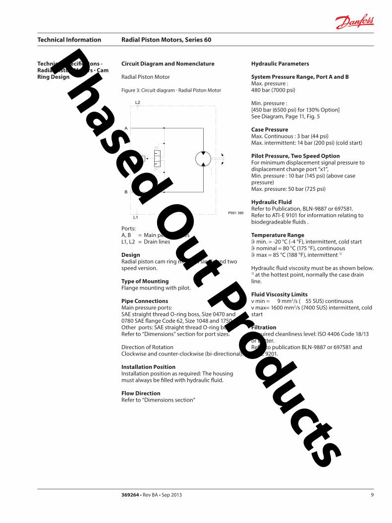
Technical Information Radial Piston Motors Series 60
369264 bull Rev BA bull Sep 2013 9
Circuit Diagram and Nomenclature
Radial Piston Motor
Figure 3 Circuit diagram middot Radial Piston Motor
PortsA B = Main pessure linesL1 L2 = Drain lines
DesignRadial piston cam ring motor in single and two speed version
Type of MountingFlange mounting with pilot
Pipe ConnectionsMain pressure ports SAE straight thread O-ring boss Size 0470 and 0780 SAE flange Code 62 Size 1048 and 1750 Other ports SAE straight thread O-ring boss Refer to ldquoDimensionsrdquo section for port sizes
Direction of Rotation Clockwise and counter-clockwise (bi-directional)
Installation PositionInstallation position as required The housing must always be filled with hydraulic fluid
Flow DirectionRefer to ldquoDimensions sectionrdquo
Hydraulic Parameters
System Pressure Range Port A and BMax pressure 480 bar (7000 psi)
Min pressure [450 bar (6500 psi) for 130 Option] See Diagram Page 11 Fig 5
Case PressureMax Continuous 3 bar (44 psi) Max intermittent 14 bar (200 psi) (cold start)
Pilot Pressure Two Speed OptionFor minimum displacement signal pressure to displacement change port ldquox1rdquo Min pressure 10 bar (145 psi) (above case pressure) Max pressure 50 bar (725 psi)
Hydraulic FluidRefer to Publication BLN-9887 or 697581 Refer to ATI-E 9101 for information relating to biodegradeable fluids
Temperature Rangeϑ min = -20 degC (-4 degF) intermittent cold startϑ nominal = 80 degC (175 degF) continuousϑ max = 85 degC (188 degF) intermittent 1)
Hydraulic fluid viscosity must be as shown below1) at the hottest point normally the case drain line
Fluid Viscosity Limitsν min = 9 mm2s ( 55 SUS) continuous ν max= 1600 mm2s (7400 SUS) intermittent cold start
FiltrationRequired cleanliness level ISO 4406 Code 1813 or betterRefer to publication BLN-9887 or 697581 and ATI-E 9201
Technical Specificatons - Radial Piston Motors Cam Ring Design
P001 390
B
L1
A
L2
Phased Out Products
Technical Information Radial Piston Motors Series 60
5369264 bull Rev BA bull Sep 201310
Technical Data ndash Radial Piston Motors
Table 1
Determination of Nominal Motor Size (Metric System)
Vg middot nInput flow Qe = mdashmdashmdashmdash lmin 1000 middot ηv
Vg middot Dp middot ηmhOutput torque Me = mdashmdashmdashmdashmdash Nm 20 middot π
Vg = Motor displacement per rev cm3 Dp = pHD - pND bar ηv = Motor volumetric efficiency ηmh = Motor mechanical ndash hydraulic (Torque) efficiency
Me middot n Qe middot Dp middot ηt Output power Pe = mdashmdashmdashmdash = mdashmdashmdashmdashmdash kW 9950 600
Qe middot 1000 middot ηvSpeed n = mdashmdashmdashmdashmdash min-1
Vg
ηv = Motor overall efficiency pHD = High pessure barpND = Low pressure bar
Frame Size
(Dimension) 0470 0780Displacement - Option 90 100 100 110 120 130
Displacement Vg cm 3 423 470 517 564 611 702 780 858 936 1014
in3
Vg 05 cm 3 212 235 259 282 306 351 390 429 468 507in3
Rated Speed n min -1 (RPM) 235 200
Output Speed max n min -1 (RPM) 310 295 280 270 260 260 250 240 230 220Theoretical Torque at Vg Nm bar 673 748 823 898 972 1117 1241 1366 1490 1614
lbfbullin1000 psi 4117 4576 5035 5494 5946 6833 7592 8357 9115 9874
Vg 05 Nm bar 337 374 411 449 486 559 621 683 745 807lbfbullin1000 psi 2062 2288 2514 2747 2973 3420 3799 4178 4558 4937
Max Flow at Vg Q l min 131 138 145 152 159 183 195 206 215 223
galmin (US
Max Flow at Vg 05 Q l min 66 69 72 76 79 91 98 103 108 112
galmin (US
Output PowerSingle Speed at Vg kW 29 41
hp 39 55
Two Speed P kW 19 27pref Direction Vg 05 hp 25 36
Two Speed P kW 14 20
not pref Direction Vg 05 hp 19 27
Weight
Wheel Motor m kg 46 74
lb 101 163
Flange Motor m kg 42 71
lb 93 157
Shaft Motor m kg 49 72lb 108 159
P
110 120 130 90
259 287 315 344 373 428 476 524 571 619
173 183 191 201 210 241 257 272 284 294
129 143 158 172 187 214 238 262 285 309
346 366 382 402 420 482 515 544 568 589
Phased Out Products
Technical Information Radial Piston Motors Series 60
369264 bull Rev BA bull Sep 2013 11
Technical Data ndash Radial Piston Motors (cont)
Table 2
Determination of Nominal Motor Size (Inch System)
Vg middot nInput flow Qe = mdashmdashmdashmdash galmin US 231 middot ηv
Vg middot Dp middot ηmhOutput torque Me = mdashmdashmdashmdashmdash lbf in 24 middot π
Vg = Motor displacement per rev in3 Dp = pHD - pND psi ηv = Motor volumetric efficiency ηmh = Motor mechanical ndash hydraulic (Torque) efficiency
Me middot n Qe middot Dp middot ηt Output power Pe = mdashmdashmdashmdash = mdashmdashmdashmdashmdash HP 5252 1715
Qe middot 231 middot ηvSpeed n = mdashmdashmdashmdashmdash min-1
Vg
ηv = Motor overall efficiency pHD = High pessure psipND = Low pressure psi
Frame Size
(Dimension) 1048 1750Displacement - Option 90 100 110 120 130 100 110 120 130
Displacement Vg cm 3 943 1048 1153 1258 1362 1575 1750 1925 2100 2275in3 575 640 704 768 831 961 107 1175 1281 1388
Vg 05 cm3 472 524 576 629 681 788 875 963 1050 1138in3
Rated Speed n min -1 (RPM) 180 150
Output Speed max n min -1 (RPM) 240 230 215 210 200 200 195 185 175 170Theoretical Torque at Vg Nm bar 1501 167 1835 2002 2168 2507 2785 3064 3342 3621
lbfbullin1000 psi 9183 10217 11226 12248 13263 15337 17038 18745 20445 22152
Vg 05 Nm bar 750 834 918 1001 1084 1253 1393 1532 1671 1810lbfbullin1000 psi 4588 5102 5616 6124 6632 7665 8522 9372 10223 11073
Max Flow at Vg Q l min 226 241 248 264 272 315 341 356 368 387
galmin (US
Max Flow at Vg 05 Q l min 113 121 124 132 136 158 171 178 184 193
galmin (US
Output PowerSingle Speed at Vg P kW 50 70
hp 67 94
Two Speed P kW 33 47 pref Direction Vg 05 hp 44 63Two Speed P kW 25 35
not pref Direction Vg 05 hp 34 47
Weight
Wheel Motor m kg 99 149
lb 218 329
Flange Motor m kg 95 144
lb 209 318
Shaft Motor m kg 96 152lb 212 335
90
288 320 351 384 416 481 534 588 641 694
600 636 655 697 718 832 901 940 970 1021
299 318 327 349 359 416 450 470 485 511
Phased Out Products
Technical Information Radial Piston Motors Series 60
5369264 bull Rev BA bull Sep 201312
Speed RangeThe Rated Speed is the max speed recommended at max permitted operating power at which normal life can be expected All other operating conditions (eg fluid viscosity and temperature charge pressure) must be within recom-mended ranges
Maximum Speed is the max operating speed permitted and cannot be exceeded without reduction in the life of the product or risking immediate failure and loss of driveline power (which may create a safety hazard)
W Braking Warning The loss of hydrostatic driveline power in any mode (eg acceleration deceleration or neutral mode of operation) may cause a loss of braking capacity A braking system which is independent of the hydrostatic transmission must therefore be provided which is adequate to stop and hold the system should the condition develop
System Pressure RangeSystem pressure is a dominant operating variable affecting hydraulic unit life High pressure which results from high load reduces expected life in a manner similar to many mechanical assemblies such as engines and gearboxes The maximum pressure is the highest intermittent pres-sure allowed It is determined by the maximum machine load demand Maximum pressure is assumed to occur a small percentage of operating time usually less than 2 of the total Maximum pressure is normally the relief valve setting It is desirable to have a machine duty cycle with the percentage of time at various loads and speeds An appro-priate design pressure can be calculated by our application department from this information This method of selecting operating pressure is recommended whenever duty cycle information is available
Case PressureUnder normal operating conditions the maximum continu-ous case pressure must not exceed 3 bar (44 psi) Maximum allowable intermittent case pressure during cold start must no exceed 14 bar (200 psi)
Hydraulic FluidsUse only recommended hydraulic fluids in accordance to manual BLN-9887 697581 and ATI-E 9101 While fluids containing anti-wear additives are not necessary for the satisfactory performance of the series 60 units they are often required for associated equipment These fluids must possess good thermal and hydrolytic stability to prevent wear erosion and corrosion of internal compo-nents It is not permissible to mix hydraulic fluids Fire-resistant fluids are also suitable at modified
Temperature LimitsRefer to page 7 for maximum allowable temperatures for petroleum based fluids These temperature limits apply at the hottest point of the transmission which is normally the case drain Heat exchangers should be sized to keep the fluid within the limits
Loop FlushingSeries 60 motors incorporate an integral loop flushing valve Installations that require additional fluid to be removed from the main hydraulic circuit because of fluid cooling requirements or circuits requiring the removal of excessive contamination from the high pressure circuit can benefit from loop flushing Series 60 motors with an integral loop flushing valve also include a purge pressure relief valve The setting of the motor charge relief valve affects the function of the flushing circuit Higher motor purge relief settings reduce the loop flushing flow and increase the flow over the pump charge pressure relief valve when the circuit is operating Lower motor purge relief settings increase the loop flushing flow and may increase the motor case pressure when the circuit is operating An appropriate combination of pump and motor charge pressure settings should be maintained to insure the proper function of the loop flushing circuit Correct charge pressure must be maintained under all conditions of operation to maintain control performance in closed loop systems
Figure 4 Loop Flushing Valve
General Technical Specifications
P001 397
Phased Out Products
Technical Information Radial Piston Motors Series 60
369264 bull Rev BA bull Sep 2013 13
Figure 5 Minimum charge pressure (above Case Pressure) Single Speed and Two Speed MotorGeneral Technical Specifications (Continued)
Charge Pressure Requirements
Park BrakeBrake Description
The brake is of the multiple-plate type A belleville spring washer is acting against the piston pressing stationary and rotating discs against each other When the brake piston is pressurized the force on the piston overcomes the force of the belleville spring and releases the brake
Figure 6 Circuit Diagramm
To move the vehicle or machine without the availability of brake release pressure a mechanical release option is available The torque specified for this brake is only validated under static conditions
Figure 7 Brake section View
P001 420E
Two SpeedMotor
Single SpeedMotor
0 20 40 60 80 100
Output Speed max speed
0
2 (30)
4 (60)
6 (90)
8 (120)
10 (150)
12 (180)
14 (210)
16 (240)
Min
Pre
ssur
e ba
r (ps
i)
18 (270)
20 (300)
P001 439 P001 406
Table 3 Input Brakes
DimensionFrame Size
0470 0780 1048 1750
Brake Torque static permitted (Applies for petroleum based fluid)
Nm 2500 4200 5700 9600lbin 22 100 37 100 50 400 84 900
Brake release pressure above case pressure
bar 15 min 30 maxpsi 218 min 435 max
Phased Out Products
Technical Information Radial Piston Motors Series 60
5369264 bull Rev BA bull Sep 201314
Series 60 Motors run in freewheeling mode with almost no losses The necessary valving needs to be added into the circuit The schematic below shows a solution closed circuit operation
The following has to be provided y The high pressure ports of the motor are
connected to the tank y A low pressure is applied to the motor drain
port (Fig 8)which pushes the pistons into their cylinders (Fig9) disengaging them from the cam The necessary case pressure is shown on table 4
General Technical Specifications (Continued)
Freewheeling Option
Speed Pick-Up
Shock Load
Table 4 Max speeds in freewheeling condition
Case pressure 15 bar (22 psi)above ports A and B Dimension
Frame Size0470 0780 1048 1750
Freewheeling Output Speed max min-1 (RPM) 770 630 560 450
Figure 8 Circuit Diagramm Figure 9 Motor Section View Fig 10 Circuit DiagrammFreewheeling Option Freewheeling mode Two Speed Option
P001 440 P001 441 P001 449
B
L1
A
x1
L2
Two Speed OptionThe Two Speed Option is available on all motor sizes allowing increased application flexibility The integral displacement change valve selects half displacement When the displacement change port ldquox1rdquo (Fig 10) is connected to tank or motor case pressure maximum displacement is selected
When a signal pressure min 10 bar ( 145 psi) above case pressure [max 50 bar ( 725 psi)] is connected to ldquox1rdquo minimum displacement is selected Motor performance and life is optimal in the preferred direction of rotation (see Dimensions) The displacement should be changed while the motor is stationary This avoids sudden or unexpected speed changes and possible transmission damage
Series 60 Motors speed pick-up (Hall Effect Sensor) is especially designed for rough outdoor mobile or heavy industrial applications where speed monitoring revolution counting speed limit control or alarm function is required with no physical contact with the sensed motor shaft
Pin 1 Supply voltage = 45 to 16 V dc Supply current At 5 V -16 mA Pin 2 Not usedPin 3 Output digital open collector NPN Pin 4 Ground For installation and connector details see Fig 28 page 23
Table 5 Pulse Frequency
Motor Frame Size 0470 0780 1048 1750Pulses per revolution 78 92 101 121
Motors are designed for 20 g external accelleration
Phased Out Products
Technical Information Radial Piston Motors Series 60
369264 bull Rev BA bull Sep 2013 15
Figure 11 shows the volumetric mechanical and overall efficiencies of a typical Series 60 single and two speed motor at full displacement and system pressures of 200 bar (2900 psi) and 400 bar (5800 psi) with a fluid viscosity of 20 mm2s (98 SUS) at a temperature of 60 degC (140 degF)
Figure 12 shows the overall efficiency of a typical Series 60 single and two speed motor at full displacement with system pressure up to 480 bar (7000 psi) with a fluid viscosity of 20mm2s ( 98 SUS) at a temperature of 60 degC (140 degF)
General Technical Specifications (Continued)
Efficiency Graphs and Maps
Figure 11 Volumetric Mechanical and Overall Efficiency
Figure 12 Overall Efficiency
P001 392ESpeed of rated speed
Eci
ency
0 25 50 75 100
74
76
78
80
82
84
86
88
90
92
94
96
98
100
ηt = 400 bar (5800 psi)
Overall Eciencyηt = 200 bar (2900 psi)
Volumetric Eciencyηv = 200 bar (2900 psi)
ηm= 400 bar (5800 psi)
ηv = 400 bar (5800 psi)
Mechanical Eciency ηm = 200 bar (2900 psi)
Speed of rated speed
0
Syst
em p
ress
ure
∆p
bar (
psi)
25 75 100
85
8992
94
95
80
500
480 (7000)
300 (4350)
200 (2900)
100 (1450)
400 (5800)
500 (7250)
P001 394E
Phased Out Products
Technical Information Radial Piston Motors Series 60
5369264 bull Rev BA bull Sep 201316
Figure 13 shows the volumetric mechanical and overall efficiencies of a typical Series 60 single and two speed motor at half displacement in the preferred direction and system pressures of 200 bar (2900 psi) and 400 bar (5800 psi) with a fluid viscosity of 20 mm2s ( 98 SUS) at a temperature of 60deg C (140deg F)
Figure 14 shows the overall efficiency of a typical Series 60 single and two speed motor at half displacement in the preferred direction and system pressure up to 480 bar (7000) psi) with a fluid viscosity of 20 mm2s ( 98 SUS) at a temperature of 60 degC (140 deg F)
General Technical Specifications (Continued)
Efficiency Graphs and Maps
Figure 13 Volumetric Mechanical and Overall Efficiency at half displacement in the preferred direction
Figure 14 Overall Efficiency at half displacement in the preferred direction
P001 393 E
Speed of rated speed
Eci
ency
ηm= 200 bar (2900 psi)
0 25 50 75 100
65
70
75
80
85
90
95
100Volumetric Eciency ηv = 200 bar (2900 psi)
Mech Eciencyηm= 400 bar (5800 psi)
Overall Eciency ηt = 200 bar (2900 psi)
ηv = 400 bar (5800 psi)
ηt = 400 bar (5800 psi)
0 25 50 75
Speed of rated speed
78 84
88
9091
92
Syst
em p
ress
ure
∆p
bar (
psi)
500 (7250)
300 (4350)
200 (2900 )
100 (1450)
0
400 (5800)
480 (7000)
100P001 402 E
Phased Out Products
Technical Information Radial Piston Motors Series 60
369264 bull Rev BA bull Sep 2013 17
Dimensions60M0470 60V0470
Figure 15 Wheel Motor 60M0470 Single Speed VersionWheel Motor 60V0470 Two Speed Version
View X
TwoSpeed
L1A
B
300
(11
8)
81(319)
2020
2010
R 175R (069)
Purge Pressure Relief Valve
Case Drain Ports L1 + L2
degdeg
degdeg
Loop Flushing Shuttle Valve
L2
x1
265
(10
43)
175 +025-010
(689) +01 -004
30deg
for Speed Pick Up9 16-18UNF-2Binclined 15 degoptional
oslash05 Aoslash(02 ) A
80(315)
77(303)
94(37)
225(886)
P001 426E
oslash92
8-0
2(D
ia 3
65
-01
)
DisplacementChange Port X1716-20UNF-2B
Main Ports A + B 1 116-12UNF-2B
Studs 10x36 deg M14x15
13(51)
36(142)
6(24)
oslash14
0(D
ia 5
51)
oslash17
5(D
ia 6
89)
oslash22
3(D
ia 8
78)
Case Drain Port L1 34-16UNF-2B10deg inclined
64( L1L2 )(252)
54 (213)
7(28)
425 (167)
MountingSurface for Brake (Option)
Purge Pressure Relief Valve
312(123)
15 (59)
180(709)
oslash22
4-0
2(D
ia 8
82
-01
)
80 (32
)
67 (264)
90 (35
4)
82 (323)
505(199)
96(38)
TwoSpeed
A
10(4)
X
Single Speed MotorPortFlow
Rotation in outLH(CCW) B ARH (CW) A B
Two Speed MotorPref Rotation Right
Rotation in outLH(CCW) A BRH (CW) B A
Two Speed MotorPref Rotation Left
Rotation in outLH(CCW) B ARH (CW) A B
Rotation Radial Load Curve
P001 425E
Distance from Hub Mounting Face mm (in)
-4 -2 0 2 6-6-79 4 8 99
-200 -100 -50 0 50 100 150 200-150 250
Max
Rad
ial L
oad
kN (
lb)
0
20
40
60
4500
9000
0
13 500
18 000 80
Dynamic loadat DierentialPressure250 bar (3600 psi)
Phased Out Products
Technical Information Radial Piston Motors Series 60
5369264 bull Rev BA bull Sep 201318
Dimensions60M0470 60V0470
Figure 16 Flange Motor 60M0470 Single Speed VersionFlange Motor 60V0470 Two Speed Version
Single Speed MotorPortFlow
Rotation in outLH(CCW) B ARH (CW) A B
Two Speed MotorPref Rotation Right
Rotation in outLH(CCW) A BRH (CW) B A
Two Speed MotorPref Rotation Left
Rotation in outLH(CCW) B ARH (CW) A B
View X
X
P001 427E
TwoSpeed
L1A
B
300
(11
8)
81(319)
2020
2010
R 175R (069)
Purge Pressure Relief Valve
Case Drain Ports L1 + L2
degdeg
degdeg
Loop Flushing Shuttle Valve
L2
x1
265
(10
43)
175 +025-010
(689) +01 -004
30deg
for Speed Pick Up9 16-18UNF-2Binclined 15 degoptional
oslash05 Aoslash(02 ) A
80(315)
77(303)
94(37)
225(886)
P001 426E
Rotation Radial Load Curve
Dynamic loadat DierentialPressure250 bar (3600 psi)
Distance from Hub Mounting Face mm (in)
-4 -2 0 2 6-6-79 4 8 99
-200 -100 -50 0 50 100 150 200-150 250
Max
Rad
ial L
oad
kN (
lb)
0
20
40
60
4500
9000
13 500
0
oslash92
8-0
2(D
ia 3
65
-01
)
DisplacementChange Port X1716-20UNF-2B
Main Ports A + B 1 116-12UNF-2B25deg inclined
Studs 5x72 deg M14x15
12(47)
37(146)
6(24)
oslash14
0(D
ia 5
51)
oslash17
5(D
ia 6
89)
oslash22
3(D
ia 8
78)
Case Drain Ports L1 34-16UNF-2B10deg inclined
64( L1L2 )(252)
25 (98)
7(28)
425 (167)
MountingSurface for Brake (Option)
Purge Pressure Relief Valve
280(110)
15 (59)147(579)
oslash22
4-0
2(D
ia 8
82
-01
)
80 (32
)
67 (264)90 (3
54)
82 (323)
505(199)
96(38)
Two Speed
A
10(4)
Phased Out Products
Technical Information Radial Piston Motors Series 60
369264 bull Rev BA bull Sep 2013 19
Dimensions60M0470 60V0470
Figure 17 Shaft Motor 60M0470 Single Speed VersionShaft Motor 60V0470 Two Speed Version
Single Speed MotorPortFlow
Rotation in outLH(CCW) B ARH (CW) A B
Two Speed MotorPref Rotation Right
Rotation in outLH(CCW) A BRH (CW) B A
Two Speed MotorPref Rotation Left
Rotation in outLH(CCW) B ARH (CW) A B
View X
P001 428E
TwoSpeed
L1A
B
300
(11
8)
81(319)
2020
2010
R 175R (069)
Purge Pressure Relief Valve
Case Drain Ports L1 + L2
degdeg
degdeg
Loop Flushing Shuttle Valve
L2
x1
265
(10
43)
175 +025-010
(689) +01 -004
30deg
for Speed Pick Up9 16-18UNF-2Binclined 15 degoptional
oslash05 Aoslash(02 ) A
80(315)
77(303)
94(37)
225(886)
X
P001 426E
Rotation
Max Radial Load
DisplacementChange Port X1716-20UNF-2B
Main Ports A + B 1 116-12UNF-2B25deg inclined
Case Drain Port L1 34-16UNF-2B10deg inclined
395 (156)
18 ( L1L2 )(7)
MountingSurface for Brake (Option)
Purge Pressure Relief Valve
oslash22
3(D
ia 8
78)
80 (32
)
15 (59)
90 (35
4)
315 (124)
Two Speed
23(91)10 (39)
oslash20
0-0
07
(Dia
787
4-0
03)
312(123)
203 (799)
39(154)
54 (213)
38-
16U
NC
x15
(59)
full
THD
254
(10
)
34(134)
R25 +02(R10 +01 )
87 (343)
47(185)
Shaft Spline Data5 ssalC a1129B ISNA Spline standard
Spline Fit Pitch D
03 elgnA erusserPNo of teethSplineMajor Dia
A
-50 -40 -30 -20 -10 0
-2 -1
50
60
30
40
20
0
10
Allo
wab
lera
dial
Loa
d kN
(lb
)
Distance from Shaftshoulder mm (in)
0
2250
6750
9000
11250
4500
13500
0
Dynamic loadat ∆p = 250 bar (3600 psi)
Flat Root Side Fit4863 (1916)
231224508 (20)
Phased Out Products
Technical Information Radial Piston Motors Series 60
5369264 bull Rev BA bull Sep 201320
Dimensions60M0780 60V780
Figure 18 Wheel Motor 60M0780 Single Speed VersionWheel Motor 60V0780 TwoSpeed Version
Single Speed MotorPortFlow
Rotation in outLH(CCW) B ARH (CW) A B
Two Speed MotorPref Rotation Right
Rotation in outLH(CCW) A BRH (CW) B A
Two Speed MotorPref Rotation Left
Rotation in outLH(CCW) B ARH (CW) A B
20
40
60
80
0
4500
9000
13 500
18 000
Max
Rad
ial L
oad
kN (
lb)
Dynamic load atDierential Pressure250 bar (3600 psi)
Distance from Hub Mounting Face mm (in)
-200 -150 -100 -50 0 50 100 150 200 250
-79 -6 -4 -2 0 2 4 6 8 98
oslash16
08
-02
(Dia
63
3 -0
1)
DisplacementChange Port X1716-20UNF-2B
Main Ports A + B 1 116-12UNF-2B25deg inclined
Studs 6x60 deg M18x15
15(6)
36(142)
8(31)
oslash20
5(D
ia 8
1)
oslash24
7(D
ia 9
7)
oslash26
6(D
ia 1
05)
Case Drain Port L134-16UNF-2B10deg inclined
70( L1L2 ) (276)
58 (228)
7(28)
44 (173)
MountingSurface for Brake (Option)
Purge Pressure Relief Valve
334(123)
17 (7)
195(768)
oslash25
3-0
2(D
ia 9
96
-01
)96 (38
)
72 (283)
106
(42
)
88 (35)
51(201)
104(409)
A
TwoSpeed
17(7)
View X
for Speed Pick Up9 16-18UNF-2Binclined 15 degoptional
L2L1A
B
335
(13
2)
267(1051)
R 175R (069)
Purge Pressure Relief Valve
Case Drain Ports L1 + L2
Loop Flushing Shuttle Valve
x1
TwoSpeed
300
(11
81)
175 +025-010
(689) +01 -004
oslash05 Aoslash(02 ) A
30deg
15deg15deg
15deg15deg
96(38)
93(37)
91(36)
109(43)
P001 435E
P001 436E
Rotation Radial Load Curve
X
Phased Out Products
Technical Information Radial Piston Motors Series 60
369264 bull Rev BA bull Sep 2013 21
Dimensions60M0780 60 V780
Figure 19 Flange Motor 60M0780 Single Speed VersionFlange Motor 60V0780 Two Speed Version
Single Speed MotorPortFlow
Rotation in outLH(CCW) B ARH (CW) A B
Two Speed MotorPref Rotation Right
Rotation in outLH(CCW) A BRH (CW) B A
Two Speed MotorPref Rotation Left
Rotation in outLH(CCW) B ARH (CW) A B
View X
X
Max
Rad
ial L
oad
kN (
lb)
0
20
40
60
4500
9000
13 500
0
8018 000
Distance from Hub Mounting Face mm (in)
-4 -2 0 2 6-6-79 4 8 99
-200 -100 -50 0 50 100 150 200-150 250
Dynamic loadat DierentialPressure250 bar (3600 psi)
72 (283)
DisplacementChange Port X1716-20UNF-2B
Main Ports A + B 1 116-12UNF-2B25deg inclined
Case Drain Port L134-16UNF-2B
10deg inclined
70( L1L2 )(276)
27 (106)
7(28)
44 (173)
MountingSurface for Brake (Option)
304(119)
17 (7)
25(10)
oslash25
3-0
2(D
ia 9
96
-01
)
96 (38
)
106
(42
)
88 (35)
51(201)
104(409)
Two Speed
A
oslash16
08
-02
(Dia
63
3 -0
1)
Studs 6x60 deg M18x15
15(6)
36(142)
7(3)
oslash20
5(D
ia 8
1)
oslash24
7(D
ia 9
7)
oslash26
6(D
ia 1
05)
Purge Pressure Relief Valve
164(65)
for Speed Pick Up9 16-18UNF-2Binclined 15 degoptional
L2L1A
B
335
(13
2)
267(1051)
R 175R (069)
Purge Pressure Relief Valve
Case Drain Ports L1 + L2
Loop Flushing Shuttle Valve
x1
TwoSpeed
300
(11
81)
175 +025-010
(689) +01 -004
oslash05 Aoslash(02 ) A
30deg
15deg15deg
15deg15deg
96(38)
93(37)
91(36)
109(43)
P001 436E
P001 437E
Rotation Radial Load Curve
Phased Out Products
Technical Information Radial Piston Motors Series 60
5369264 bull Rev BA bull Sep 201322
Dimensions60M0780 60V780
Figure 20 Shaft Motor 60M0780 Single Speed VersionShaft Motor 60V0780 Two Speed Version
Single Speed MotorPortFlow
Rotation in outLH(CCW) B ARH (CW) A B
Two Speed MotorPref Rotation Right
Rotation in outLH(CCW) A BRH (CW) B A
Two Speed MotorPref Rotation Left
Rotation in outLH(CCW) B ARH (CW) A B
View X
for Speed Pick Up9 16-18UNF-2Binclined 15 degoptional
L2L1A
B
335
(13
2)
267(1051)
R 175R (069)
Purge Pressure Relief Valve
Case Drain Ports L1 + L2
Loop Flushing Shuttle Valve
x1
TwoSpeed
300
(11
81)
175 +025-010
(689) +01 -004
oslash05 Aoslash(02 ) A
30deg
15deg15deg
15deg15deg
96(38)
93(37)
91(36)
109(43)
X
P001 436E
Rotation
Max Radial Load
DisplacementChange Port X1716-20UNF-2B
Main Ports A + B1 116-12UNF-2B25deg inclined
Case Drain Port L134-16UNF-2B10deg inclined
44 (173)
18 ( L1L2 ) (71)
MountingSurface for Brake (Option)
Purge Pressure Relief Valve
oslash26
7(D
ia 1
051
)96 (38
)
16 (63)
106
(42
)
37 (146)
Two Speed
25(98)16 (63)
oslash22
4-0
15
(Dia
88
19-0
06)
343(1350)
215 (846)
40(157)
70 (276)
38-
16 U
NC
x15
(59)
full
THD
381
(15
)
46(181)
R3 +02(R12 +01 )
97 (382)
54(213)
A
-100 -80 -60 -40 -20 0
-4 -2
100
60
80
40
0
20
Allo
wab
lera
dial
Loa
d kN
(lb)
Distance from Shaftshoulder mm (in)
0
9000
13500
4500
18000
0
22500
P001 438E
Dynamic load at∆p = 250 bar (3600 psi)
Shaft Spline Data5 ssalC a1129B ISNA Spline standard
Spline Fit Pitch D
03 elgnA erusserPNo of teethSplineMajor Dia
Flat Root Side Fit635 (25)
208166667 (2625)
Phased Out Products
Technical Information Radial Piston Motors Series 60
369264 bull Rev BA bull Sep 2013 23
Dimensions60M1048 60V1048
Figure 21 Wheel Motor 60M1048 Single Speed VersionWheel Motor 60V0470 Two Speed Version
Single Speed MotorPortFlow
Rotation in outLH(CCW) B ARH (CW) A B
Two Speed MotorPref Rotation Right
Rotation in outLH(CCW) A BRH (CW) B A
Two Speed MotorPref Rotation Left
Rotation in outLH(CCW) B ARH (CW) A B
View X
P001 414E
X
P001 415E
295(1161)
x110
degdeg
L1A
B
R 20 R (079)
108(425)
108(425)
Purge Pressure Relief Valve Loop Flushing Shuttle Valve
L2
TwoSpeed37
5 (1
476
)
2020
20
Case Drain Ports L1 + L2
degdeg
335
(13
19)
225 +025-010
(89) +01 -004
30deg
for Speed Pick Up9 16-18UNF-2Binclined 15 degoptional
oslash075oslash(03 )
AA
118(465)
Rotation Radial Load Curve
20
40
60
80
100
0
4500
9000
13 500
18 000
22 500
Max
Rad
ial L
oad
kN (
lb)
Distance from Hub Mounting Face mm (in)
-200 -150 -100 -50 0 50 100 150 200 250
-79 -6 -4 -2 0 2 4 6 8 98
Dynamic load atDierentialPressure250 bar (3600 psi)
Studs 5x72 deg M22x15
Case Drain Ports L1 + L2 34-16UNF-2B
66( L2 ) (260)
565(222)
Main Ports A + B 075-Code 62Split Flange Boss per SAE J 51838-16UNC-2B 22 (088) min full thread depth
8 (31)
48 (189)
MountingSurface for Brake (Option)
16(63)
47(185)
Purge Pressure Relief Valve
112(441)
379(1492)
19 (75)
220(866)
8 (31)
oslash17
58
-02
(Dia
69
2 -0
1)
oslash22
5(D
ia 8
86)
280
(Dia
11
02)oslash
292
(Dia
115
0)
508
(20
0)
285
-02
(11
22-0
1)
96 (37
8)
DisplacementChange Port X1716-20UNF-2B
79 (31)
115
(45
3)
Two Speed
96 (378)
238(94)
81( L1 )(319)
24(9)
A
Phased Out Products
Technical Information Radial Piston Motors Series 60
5369264 bull Rev BA bull Sep 201324
Dimensions60M1048 60V1048
Figure 22 Flange Motor 60M1048 Single Speed VersionFlange Motor 60V1048 Two Speed Version
Single Speed MotorPortFlow
Rotation in outLH(CCW) B ARH (CW) A B
Two Speed MotorPref Rotation Right
Rotation in outLH(CCW) A BRH (CW) B A
Two Speed MotorPref Rotation Left
Rotation in outLH(CCW) B ARH (CW) A B
View X
X
295(1161)
x1
10deg
deg
L1A
B
R 20 R (079)
108(425)
108(425)
Purge Pressure Relief Valve Loop Flushing Shuttle Valve
L2
TwoSpeed37
5 (1
476
)
2020
20
Case Drain Ports L1 + L2
degdeg
335
(13
19)
225 +025-010
(89) +01 -004
30deg
for Speed Pick Up9 16-18UNF-2Binclined 15 degoptional
oslash075oslash(03 )
AA
118(465)
Dynamic loadat DierentialPressure250 bar (3600 psi)
Max
Rad
ial L
oad
kN (
lb)
0
20
40
60
4500
9000
13 500
0
Distance from Hub Mounting Face mm (in)
-4 -2 0 2 6-6-79 4 8 99
-200 -100 -50 0 50 100 150 200-150 250
Studs 6x60 deg M18x15
Case Drain Ports L1 + L2 34-16UNF-2B
66( L2 ) (26)
255(100)
Main Ports A + B 075-Code 62Split Flange Boss per SAE J 51838-16UNC-2B 22 (088) min full thread depth
8(31)
48 (189)
MountingSurface for Brake (Option)
15(59)
36(142)
Purge Pressure Relief Valve
112(441)
322(127)
19 (75)
1745(687)
6(24)
oslash16
08
-02
(Dia
63
3 -0
1)
oslash20
5 (D
ia 8
07)
250
(Dia
98
4)
oslash29
2(D
ia11
50)
508
(20
)
285
-02
(11
22-0
1)
96 (37
8)
DisplacementChange Port X1716-20UNF-2B
79 (311)11
5 (4
53)
Two Speed
96 (378)
238(94)
81( L1 )(319)
A
255 (10)
P001 415E
Rotation Radial Load Curve
P001 416E
Phased Out Products
Technical Information Radial Piston Motors Series 60
369264 bull Rev BA bull Sep 2013 25
Dimensions60M1048 60V1048
Figure 23 Shaft Motor 60M1048 Single Speed VersionShaft Motor 60M1048 Two Speed Version
Single Speed MotorPortFlow
Rotation in outLH(CCW) B ARH (CW) A B
Two Speed MotorPref Rotation Right
Rotation in outLH(CCW) A BRH (CW) B A
Two Speed MotorPref Rotation Left
Rotation in outLH(CCW) B ARH (CW) A B
View X
295(1161)
x110
degdeg
L1A
B
R 20 R (079)
108(425)
108(425)
Purge Pressure Relief Valve Loop Flushing Shuttle Valve
L2
TwoSpeed37
5 (1
476
)
2020
20
Case Drain Ports L1 + L2
degdeg
335
(13
19)
225 +025-010
(89) +01 -004
30deg
for Speed Pick Up9 16-18UNF-2Binclined 15 degoptional
oslash075oslash(03 )
AA
118(465)
P001 415E
Rotation
Max Radial Load
X
73 ( L1 )(287)
28(110)13 (51)
oslash28
0-0
15
(Dia
110
24-0
06)
372(146)
2325 (915)
50 (197)
70 (276)
38-
16U
NC
15 (
59) f
ull T
HD
381
(15
)
46(181)
123 (484)
R 3 +02(R12 +01 )
515 (203)
Main Ports A + B 075-Code 62Split Flange Boss per SAE J 51838-16UNC-2B22 (088) min full thread depth
Case Drain Ports L1+L234-16UNF-2B
40 (157)
MountingSurface for Brake (Option)
104(41)
238(94)
508
(20
0)
oslash29
2(D
ia11
5)96 (37
8)
DisplacementChange Port X1716-20UNF-2B
17(67)
115
(45
3)
Two Speed
58( L2 )(228)
PurgePressureRelief ValveA
-100 -80 -60 -40 -20 0
-4 -2
120
60
80
40
0
20
Allo
wab
lera
dial
Loa
d kN
(lb)
Distance from Shaftshoulder mm (in)
0
9000
13500
4500
18000
0
22500 10027000
P001 417E
Dynamic load at ∆p = 250 bar (3600 psi)
Shaft Spline Data5 ssalC a1129B ISNA Spline standard
Spline Fit Pitch Dia
03 elgnA erusserPNo of teethSplineMajor Dia
Flat Root Side Fit73025 (30)
23816762 (30)
Phased Out Products
Technical Information Radial Piston Motors Series 60
5369264 bull Rev BA bull Sep 201326
Dimensions60M1750 60V1750
Figure 24 Wheel Motor 60M1750 Single Speed VersionWheel Motor 60V1750 Two Speed Version
Single Speed MotorPortFlow
Rotation in outLH(CCW) B ARH (CW) A B
Two Speed MotorPref Rotation Right
Rotation in outLH(CCW) A BRH (CW) B A
Two Speed MotorPref Rotation Left
Rotation in outLH(CCW) B ARH (CW) A B
View X
X
Rotation Radial Load Curve
P001 430E
P001 429E
L2L1A
B
425
(16
73)
Purge Pressure Relief Valve
Case Drain Ports L1 + L2
Loop Flushing Shuttle Valve
x1
Two Speed
385
(15
16)
225 +025-010
(89) +01 -004
oslash075 Aoslash(03 ) A
30deg
for Speed Pick Up9 16-18UNF-2Binclined 15 degoptional
15deg15deg
15deg15deg
350(1378)
R 20 R (079)
124(488)
124(488)
138(543)
Dynamic load atDierentialPressure250 bar (3600 psi)
(in)Distance from Hub Mounting Face mm
-200 -150 -100 -50 0 50 100 150 200 250
-79 -6 -4 -2 0 2 4 6 8 98
Max
Rad
ial L
oad
kN (
lb)
20
40
140
160
60
80
100
120
180
0
4500
9000
13 500
27 000
36 000
18 000
22 500
31 500
40 500
0
Studs 10x36 deg M22x15
Case Drain Ports L1 + L2 78-14UNF-2B
69(272)
Main Ports A + B 100-Code 62Split Flange Boss per SAE J 518716-14UNC-2B 27 (106) min full thread depth
11(43)
66 (2598)
MountingSurface for Brake (Option)
16(63)
47(185)
Purge Pressure Relief Valve
132(520)
433(1705)
225 (886)
254(100)
8 (31)
oslash17
58
-02
(Dia
69
2 -0
1)
oslash22
5(D
ia 8
86)
280
(Dia
11
02)oslash
350
(Dia
137
8)
571
5(2
25)
oslash33
0-0
2(D
ia12
992
-008
)
115
(45
28)
DisplacementChange Port X1716-20UNF-2B
99 (390)
141
(55
5)
Two Speed
116 (4567)
2776(1093)
96( L1L2 )(378)
20(0787)
A
Phased Out Products
Technical Information Radial Piston Motors Series 60
369264 bull Rev BA bull Sep 2013 27
Dimensions60M1750 60V1750
Figure 25 Flange Motor 60M1750 Single Speed VersionFlange Motor 60V1750 Two Speed Version
Single Speed MotorPortFlow
Rotation in outLH(CCW) B ARH (CW) A B
Two Speed MotorPref Rotation Right
Rotation in outLH(CCW) A BRH (CW) B A
Two Speed MotorPref Rotation Left
Rotation in outLH(CCW) B ARH (CW) A B
View X
X
P001 430E
Rotation Radial Load Curve
P001 431E
L2L1A
B
425
(16
73)
Purge Pressure Relief Valve
Case Drain Ports L1 + L2
Loop Flushing Shuttle Valve
x1
Two Speed
385
(15
16)
225 +025-010
(89) +01 -004
oslash075 Aoslash(03 ) A
30deg
for Speed Pick Up9 16-18UNF-2Binclined 15 degoptional
15deg15deg
15deg15deg
350(1378)
R 20 R (079)
124(488)
124(488)
138(543)
0
Dynamic loadat DierentialPressure250 bar (3600 psi)
Distance from Hub Mounting Face mm (in)
-6 -4 -2 0 2 64 8 99-79
-200 -100 -50 0 50 100 150 200-150 250
Max
Rad
ial L
oad
kN (
lb)
0
20
40
60
4500
9000
13 500
8018 000
10022 500
12027 000
14031 500
16036 000
18040 500
Studs 10x36 deg M22x15
Case Drain Ports L1 + L2 78-14UNF-2B
32(126)
Main Ports A + B 100-Code 62Split Flange Boss per SAE J 518716-14UNC-2B 27 (106) min full thread depth
11(43)
66 (2598)
MountingSurface for Brake (Option)
16(63)
47(185)
Purge Pressure Relief Valve
132(520)
389(1531)
225 (886)
210(1827)
8 (31)
oslash17
58
-02
(Dia
69
2 -0
1)
oslash22
5(D
ia 8
86)
280
(Dia
11
02)oslash
350
(Dia
137
8)
571
5(2
25)
oslash33
0-0
2(D
ia 1
299
2-0
08)
115
(45
28)
DisplacementChange Port X1716-20UNF-2B
99 (390)
141
(55
5)
Two Speed
116 (4567)
2776(1093)
96( L1 L2 )(378)
29 (114)
A
Phased Out Products
Technical Information Radial Piston Motors Series 60
5369264 bull Rev BA bull Sep 201328
Dimensions60M1750 60V1750
Figure 26 Shaft Motor 60M1750 Single Speed VersionShaft Motor 60V1750 Two Speed Version
Single Speed MotorPortFlow
Rotation in outLH(CCW) B ARH (CW) A B
Two Speed MotorPref Rotation Right
Rotation in outLH(CCW) A BRH (CW) B A
Two Speed MotorPref Rotation Left
Rotation in outLH(CCW) B ARH (CW) A B
View X
L2L1A
B
425
(16
73)
Purge Pressure Relief Valve
Case Drain Ports L1 + L2
Loop Flushing Shuttle Valve
x1
Two Speed
385
(15
16)
225 +025-010
(89) +01 -004
oslash075 Aoslash(03 ) A
30deg
for Speed Pick Up9 16-18UNF-2Binclined 15 degoptional
15deg15deg
15deg15deg
350(1378)
R 20 R (079)
124(488)
124(488)
138(543)
P001 430E
Rotation
X
Max Radial Load
Displacementchange Port X1716-20UNF-2B
24(94)15 (59)
oslash31
5-0
15
(Dia
124
02-0
06)
440(173)
2835 (1116)
48 (189)
90 (354)
12-
13 U
NC
X22
(86)
full
THD
381
(15
)
63(248)
141 (555)
R4 +02(R16 +01 )
97 (382)
Main Ports A + B 100-Code 62Split Flange Boss per SAE J 518716-14UNC-2B27 (106) min full thread depth
Case Drain Ports L1+L278-20UNF-2B
20 (079) ( L1+L2 )
50 (197)
MountingSurface for Brake (Option)Purge Pressure
Relief Valve
121 (48)
278(109)
572
(22
5)
oslash33
0(D
ia12
99)11
5 (4
53)
17 (67)
141
(55
5)
Two Speed
9 (35)
oslash35
0(D
ia13
78)
A
-100 -80 -60 -40 -20 0
-4 -2
200
100
150
0
50
Allo
wab
lera
dial
Loa
d kN
(lb)
Distance from Shaftshoulder mm (in)
0
22500
11250
33750
0
45000
P001 432E
Dynamic load at ∆p = 250 bar (3600 psi)
Shaft Spline Data5 ssalC a1129B ISNA Spline standard
Spline Fit Pitch Dia
03 elgnA erusserPNo of teethSplineMajor Dia
Flat Root Side Fit889 (35)
288169207 (3625)
Phased Out Products
Technical Information Radial Piston Motors Series 60
369264 bull Rev BA bull Sep 2013 29
NotesPhased Out Products
Technical Information Radial Piston Motors Series 60
5369264 bull Rev BA bull Sep 201330
DimensionsBrakes
Figure 27 Radial Piston Motor with Brake (0ptional)
P001 418E
Table 6 Brake Dimensions
Series Dimension
A B C
60M0470 23 (090) 74 (290) oslash212 (Dia 835)
60M0780 42 (165) 100 (394) oslash245 (Dia 965)
60M1048 30 (118) 90 (354) oslash280 (Dia 1102)
60M1750 38 (147) 107 (421) oslash320 (Dia 1260)
B
CX7
MountingFace
Mechanical BrakeRelease 1 to be used with Mech Brake Release 2
Mechanical BrakeRelease 2to be used with Mech Brake Release 1
A
Hydraulic BrakeRelease X7916-18UNF-2B
Mechanical BrakeRelease 1 to be used with Mech Brake Release 2
Mechanical BrakeRelease 2to be used with Mech Brake Release 1
TwoSpeed
X
View X
Phased Out Products
Technical Information Radial Piston Motors Series 60
369264 bull Rev BA bull Sep 2013 31
DimensionsSpeed Sensor
Figure 28 Radial Piston Motor with Speed Sensor (0ptional)
Section A - A (11)Speed Sensor
Connecto IdNoStraightRight angle
Connector is not supplied with the motorPlease order separatly using above Id No
Table 7 Speed Sensor Connector
Electrical details see page12
P001 444E
A
A
30deg 15 deg
31m
ax (1
22)
Pin 1Pin 2
Pin 3
Pin 4
Key Way
Wrench-Flats
Connector Insert
View Y
Y
127
(50)
500724500725
Phased Out Products
Comatrolwwwcomatrolcom
Schwarzmuumlller-Inverterwwwschwarzmueller-invertercom
Turolla wwwturollaocgcom
Valmovawwwvalmovacom
Hydro-Gear wwwhydro-gearcom
Daikin-Sauer-Danfosswwwdaikin-sauer-danfosscom
Danfoss Power Solutions is a global manufacturer and supplier of high-quality hydraulic and electronic components We specialize in providing state-of-the-art technology and solutions that excel in the harsh operating conditions of the mobile off -highway market Building on our extensive applications expertise we work closely with our customers to ensure exceptional performance for a broad range of off -highway vehicles
We help OEMs around the world speed up system development reduce costs and bring vehicles to market faster Danfoss ndash Your Strongest Partner in Mobile Hydraulics
Go to wwwpowersolutionsdanfosscom for further product information
Wherever off -highway vehicles are at work so is Danfoss
We off er expert worldwide support for our customers ensuring the best possible solutions for outstanding performance And with an extensive network of Global Service Partners we also provide comprehensive global service for all of our components
Please contact the Danfoss Power Solution representative nearest you
Products we off er
Bent Axis Motors
Closed Circuit Axial Piston Pumps and Motors
Displays
Electrohydraulic Power Steering
Electrohydraulics
Hydraulic Power Steering
Integrated Systems
Joysticks and Control Handles
Microcontrollers and Software
Open Circuit Axial Piston Pumps
Orbital Motors
PLUS+1reg GUIDE
Proportional Valves
Sensors
Steering
Transit Mixer Drives
Local address
Danfoss can accept no responsibility for possible errors in catalogues brochures and other printed material Danfoss reserves the right to alter its products without notice This also applies to products already on order provided that such alterations can be made without subsequential changes being necessary in specifications already agreedAll trademarks in this material are property of the respective companies Danfoss and the Danfoss logotype are trademarks of Danfoss AS All rights reserved
Danfoss Power Solutions22F Block C Yishan RdShanghai 200233 ChinaPhone +86 21 3418 5200
Danfoss Power Solutions GmbH amp Co OHGKrokamp 35D-24539 Neumuumlnster GermanyPhone +49 4321 871 0
Danfoss Power Solutions ApSNordborgvej 81DK-6430 Nordborg DenmarkPhone +45 7488 2222
Danfoss Power Solutions US Company2800 East 13th StreetAmes IA 50010 USAPhone +1 515 239 6000
369264 bull Rev BA bull Sep 2013 wwwdanfosscom copy Danfoss AS 2013-09
Phased Out Products
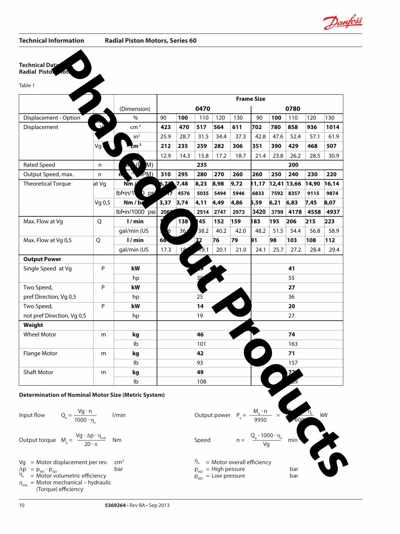
Technical Information Radial Piston Motors Series 60
369264 bull Rev BA bull Sep 2013 11
Technical Data ndash Radial Piston Motors (cont)
Table 2
Determination of Nominal Motor Size (Inch System)
Vg middot nInput flow Qe = mdashmdashmdashmdash galmin US 231 middot ηv
Vg middot Dp middot ηmhOutput torque Me = mdashmdashmdashmdashmdash lbf in 24 middot π
Vg = Motor displacement per rev in3 Dp = pHD - pND psi ηv = Motor volumetric efficiency ηmh = Motor mechanical ndash hydraulic (Torque) efficiency
Me middot n Qe middot Dp middot ηt Output power Pe = mdashmdashmdashmdash = mdashmdashmdashmdashmdash HP 5252 1715
Qe middot 231 middot ηvSpeed n = mdashmdashmdashmdashmdash min-1
Vg
ηv = Motor overall efficiency pHD = High pessure psipND = Low pressure psi
Frame Size
(Dimension) 1048 1750Displacement - Option 90 100 110 120 130 100 110 120 130
Displacement Vg cm 3 943 1048 1153 1258 1362 1575 1750 1925 2100 2275in3 575 640 704 768 831 961 107 1175 1281 1388
Vg 05 cm3 472 524 576 629 681 788 875 963 1050 1138in3
Rated Speed n min -1 (RPM) 180 150
Output Speed max n min -1 (RPM) 240 230 215 210 200 200 195 185 175 170Theoretical Torque at Vg Nm bar 1501 167 1835 2002 2168 2507 2785 3064 3342 3621
lbfbullin1000 psi 9183 10217 11226 12248 13263 15337 17038 18745 20445 22152
Vg 05 Nm bar 750 834 918 1001 1084 1253 1393 1532 1671 1810lbfbullin1000 psi 4588 5102 5616 6124 6632 7665 8522 9372 10223 11073
Max Flow at Vg Q l min 226 241 248 264 272 315 341 356 368 387
galmin (US
Max Flow at Vg 05 Q l min 113 121 124 132 136 158 171 178 184 193
galmin (US
Output PowerSingle Speed at Vg P kW 50 70
hp 67 94
Two Speed P kW 33 47 pref Direction Vg 05 hp 44 63Two Speed P kW 25 35
not pref Direction Vg 05 hp 34 47
Weight
Wheel Motor m kg 99 149
lb 218 329
Flange Motor m kg 95 144
lb 209 318
Shaft Motor m kg 96 152lb 212 335
90
288 320 351 384 416 481 534 588 641 694
600 636 655 697 718 832 901 940 970 1021
299 318 327 349 359 416 450 470 485 511
Phased Out Products
Technical Information Radial Piston Motors Series 60
5369264 bull Rev BA bull Sep 201312
Speed RangeThe Rated Speed is the max speed recommended at max permitted operating power at which normal life can be expected All other operating conditions (eg fluid viscosity and temperature charge pressure) must be within recom-mended ranges
Maximum Speed is the max operating speed permitted and cannot be exceeded without reduction in the life of the product or risking immediate failure and loss of driveline power (which may create a safety hazard)
W Braking Warning The loss of hydrostatic driveline power in any mode (eg acceleration deceleration or neutral mode of operation) may cause a loss of braking capacity A braking system which is independent of the hydrostatic transmission must therefore be provided which is adequate to stop and hold the system should the condition develop
System Pressure RangeSystem pressure is a dominant operating variable affecting hydraulic unit life High pressure which results from high load reduces expected life in a manner similar to many mechanical assemblies such as engines and gearboxes The maximum pressure is the highest intermittent pres-sure allowed It is determined by the maximum machine load demand Maximum pressure is assumed to occur a small percentage of operating time usually less than 2 of the total Maximum pressure is normally the relief valve setting It is desirable to have a machine duty cycle with the percentage of time at various loads and speeds An appro-priate design pressure can be calculated by our application department from this information This method of selecting operating pressure is recommended whenever duty cycle information is available
Case PressureUnder normal operating conditions the maximum continu-ous case pressure must not exceed 3 bar (44 psi) Maximum allowable intermittent case pressure during cold start must no exceed 14 bar (200 psi)
Hydraulic FluidsUse only recommended hydraulic fluids in accordance to manual BLN-9887 697581 and ATI-E 9101 While fluids containing anti-wear additives are not necessary for the satisfactory performance of the series 60 units they are often required for associated equipment These fluids must possess good thermal and hydrolytic stability to prevent wear erosion and corrosion of internal compo-nents It is not permissible to mix hydraulic fluids Fire-resistant fluids are also suitable at modified
Temperature LimitsRefer to page 7 for maximum allowable temperatures for petroleum based fluids These temperature limits apply at the hottest point of the transmission which is normally the case drain Heat exchangers should be sized to keep the fluid within the limits
Loop FlushingSeries 60 motors incorporate an integral loop flushing valve Installations that require additional fluid to be removed from the main hydraulic circuit because of fluid cooling requirements or circuits requiring the removal of excessive contamination from the high pressure circuit can benefit from loop flushing Series 60 motors with an integral loop flushing valve also include a purge pressure relief valve The setting of the motor charge relief valve affects the function of the flushing circuit Higher motor purge relief settings reduce the loop flushing flow and increase the flow over the pump charge pressure relief valve when the circuit is operating Lower motor purge relief settings increase the loop flushing flow and may increase the motor case pressure when the circuit is operating An appropriate combination of pump and motor charge pressure settings should be maintained to insure the proper function of the loop flushing circuit Correct charge pressure must be maintained under all conditions of operation to maintain control performance in closed loop systems
Figure 4 Loop Flushing Valve
General Technical Specifications
P001 397
Phased Out Products
Technical Information Radial Piston Motors Series 60
369264 bull Rev BA bull Sep 2013 13
Figure 5 Minimum charge pressure (above Case Pressure) Single Speed and Two Speed MotorGeneral Technical Specifications (Continued)
Charge Pressure Requirements
Park BrakeBrake Description
The brake is of the multiple-plate type A belleville spring washer is acting against the piston pressing stationary and rotating discs against each other When the brake piston is pressurized the force on the piston overcomes the force of the belleville spring and releases the brake
Figure 6 Circuit Diagramm
To move the vehicle or machine without the availability of brake release pressure a mechanical release option is available The torque specified for this brake is only validated under static conditions
Figure 7 Brake section View
P001 420E
Two SpeedMotor
Single SpeedMotor
0 20 40 60 80 100
Output Speed max speed
0
2 (30)
4 (60)
6 (90)
8 (120)
10 (150)
12 (180)
14 (210)
16 (240)
Min
Pre
ssur
e ba
r (ps
i)
18 (270)
20 (300)
P001 439 P001 406
Table 3 Input Brakes
DimensionFrame Size
0470 0780 1048 1750
Brake Torque static permitted (Applies for petroleum based fluid)
Nm 2500 4200 5700 9600lbin 22 100 37 100 50 400 84 900
Brake release pressure above case pressure
bar 15 min 30 maxpsi 218 min 435 max
Phased Out Products
Technical Information Radial Piston Motors Series 60
5369264 bull Rev BA bull Sep 201314
Series 60 Motors run in freewheeling mode with almost no losses The necessary valving needs to be added into the circuit The schematic below shows a solution closed circuit operation
The following has to be provided y The high pressure ports of the motor are
connected to the tank y A low pressure is applied to the motor drain
port (Fig 8)which pushes the pistons into their cylinders (Fig9) disengaging them from the cam The necessary case pressure is shown on table 4
General Technical Specifications (Continued)
Freewheeling Option
Speed Pick-Up
Shock Load
Table 4 Max speeds in freewheeling condition
Case pressure 15 bar (22 psi)above ports A and B Dimension
Frame Size0470 0780 1048 1750
Freewheeling Output Speed max min-1 (RPM) 770 630 560 450
Figure 8 Circuit Diagramm Figure 9 Motor Section View Fig 10 Circuit DiagrammFreewheeling Option Freewheeling mode Two Speed Option
P001 440 P001 441 P001 449
B
L1
A
x1
L2
Two Speed OptionThe Two Speed Option is available on all motor sizes allowing increased application flexibility The integral displacement change valve selects half displacement When the displacement change port ldquox1rdquo (Fig 10) is connected to tank or motor case pressure maximum displacement is selected
When a signal pressure min 10 bar ( 145 psi) above case pressure [max 50 bar ( 725 psi)] is connected to ldquox1rdquo minimum displacement is selected Motor performance and life is optimal in the preferred direction of rotation (see Dimensions) The displacement should be changed while the motor is stationary This avoids sudden or unexpected speed changes and possible transmission damage
Series 60 Motors speed pick-up (Hall Effect Sensor) is especially designed for rough outdoor mobile or heavy industrial applications where speed monitoring revolution counting speed limit control or alarm function is required with no physical contact with the sensed motor shaft
Pin 1 Supply voltage = 45 to 16 V dc Supply current At 5 V -16 mA Pin 2 Not usedPin 3 Output digital open collector NPN Pin 4 Ground For installation and connector details see Fig 28 page 23
Table 5 Pulse Frequency
Motor Frame Size 0470 0780 1048 1750Pulses per revolution 78 92 101 121
Motors are designed for 20 g external accelleration
Phased Out Products
Technical Information Radial Piston Motors Series 60
369264 bull Rev BA bull Sep 2013 15
Figure 11 shows the volumetric mechanical and overall efficiencies of a typical Series 60 single and two speed motor at full displacement and system pressures of 200 bar (2900 psi) and 400 bar (5800 psi) with a fluid viscosity of 20 mm2s (98 SUS) at a temperature of 60 degC (140 degF)
Figure 12 shows the overall efficiency of a typical Series 60 single and two speed motor at full displacement with system pressure up to 480 bar (7000 psi) with a fluid viscosity of 20mm2s ( 98 SUS) at a temperature of 60 degC (140 degF)
General Technical Specifications (Continued)
Efficiency Graphs and Maps
Figure 11 Volumetric Mechanical and Overall Efficiency
Figure 12 Overall Efficiency
P001 392ESpeed of rated speed
Eci
ency
0 25 50 75 100
74
76
78
80
82
84
86
88
90
92
94
96
98
100
ηt = 400 bar (5800 psi)
Overall Eciencyηt = 200 bar (2900 psi)
Volumetric Eciencyηv = 200 bar (2900 psi)
ηm= 400 bar (5800 psi)
ηv = 400 bar (5800 psi)
Mechanical Eciency ηm = 200 bar (2900 psi)
Speed of rated speed
0
Syst
em p
ress
ure
∆p
bar (
psi)
25 75 100
85
8992
94
95
80
500
480 (7000)
300 (4350)
200 (2900)
100 (1450)
400 (5800)
500 (7250)
P001 394E
Phased Out Products
Technical Information Radial Piston Motors Series 60
5369264 bull Rev BA bull Sep 201316
Figure 13 shows the volumetric mechanical and overall efficiencies of a typical Series 60 single and two speed motor at half displacement in the preferred direction and system pressures of 200 bar (2900 psi) and 400 bar (5800 psi) with a fluid viscosity of 20 mm2s ( 98 SUS) at a temperature of 60deg C (140deg F)
Figure 14 shows the overall efficiency of a typical Series 60 single and two speed motor at half displacement in the preferred direction and system pressure up to 480 bar (7000) psi) with a fluid viscosity of 20 mm2s ( 98 SUS) at a temperature of 60 degC (140 deg F)
General Technical Specifications (Continued)
Efficiency Graphs and Maps
Figure 13 Volumetric Mechanical and Overall Efficiency at half displacement in the preferred direction
Figure 14 Overall Efficiency at half displacement in the preferred direction
P001 393 E
Speed of rated speed
Eci
ency
ηm= 200 bar (2900 psi)
0 25 50 75 100
65
70
75
80
85
90
95
100Volumetric Eciency ηv = 200 bar (2900 psi)
Mech Eciencyηm= 400 bar (5800 psi)
Overall Eciency ηt = 200 bar (2900 psi)
ηv = 400 bar (5800 psi)
ηt = 400 bar (5800 psi)
0 25 50 75
Speed of rated speed
78 84
88
9091
92
Syst
em p
ress
ure
∆p
bar (
psi)
500 (7250)
300 (4350)
200 (2900 )
100 (1450)
0
400 (5800)
480 (7000)
100P001 402 E
Phased Out Products
Technical Information Radial Piston Motors Series 60
369264 bull Rev BA bull Sep 2013 17
Dimensions60M0470 60V0470
Figure 15 Wheel Motor 60M0470 Single Speed VersionWheel Motor 60V0470 Two Speed Version
View X
TwoSpeed
L1A
B
300
(11
8)
81(319)
2020
2010
R 175R (069)
Purge Pressure Relief Valve
Case Drain Ports L1 + L2
degdeg
degdeg
Loop Flushing Shuttle Valve
L2
x1
265
(10
43)
175 +025-010
(689) +01 -004
30deg
for Speed Pick Up9 16-18UNF-2Binclined 15 degoptional
oslash05 Aoslash(02 ) A
80(315)
77(303)
94(37)
225(886)
P001 426E
oslash92
8-0
2(D
ia 3
65
-01
)
DisplacementChange Port X1716-20UNF-2B
Main Ports A + B 1 116-12UNF-2B
Studs 10x36 deg M14x15
13(51)
36(142)
6(24)
oslash14
0(D
ia 5
51)
oslash17
5(D
ia 6
89)
oslash22
3(D
ia 8
78)
Case Drain Port L1 34-16UNF-2B10deg inclined
64( L1L2 )(252)
54 (213)
7(28)
425 (167)
MountingSurface for Brake (Option)
Purge Pressure Relief Valve
312(123)
15 (59)
180(709)
oslash22
4-0
2(D
ia 8
82
-01
)
80 (32
)
67 (264)
90 (35
4)
82 (323)
505(199)
96(38)
TwoSpeed
A
10(4)
X
Single Speed MotorPortFlow
Rotation in outLH(CCW) B ARH (CW) A B
Two Speed MotorPref Rotation Right
Rotation in outLH(CCW) A BRH (CW) B A
Two Speed MotorPref Rotation Left
Rotation in outLH(CCW) B ARH (CW) A B
Rotation Radial Load Curve
P001 425E
Distance from Hub Mounting Face mm (in)
-4 -2 0 2 6-6-79 4 8 99
-200 -100 -50 0 50 100 150 200-150 250
Max
Rad
ial L
oad
kN (
lb)
0
20
40
60
4500
9000
0
13 500
18 000 80
Dynamic loadat DierentialPressure250 bar (3600 psi)
Phased Out Products
Technical Information Radial Piston Motors Series 60
5369264 bull Rev BA bull Sep 201318
Dimensions60M0470 60V0470
Figure 16 Flange Motor 60M0470 Single Speed VersionFlange Motor 60V0470 Two Speed Version
Single Speed MotorPortFlow
Rotation in outLH(CCW) B ARH (CW) A B
Two Speed MotorPref Rotation Right
Rotation in outLH(CCW) A BRH (CW) B A
Two Speed MotorPref Rotation Left
Rotation in outLH(CCW) B ARH (CW) A B
View X
X
P001 427E
TwoSpeed
L1A
B
300
(11
8)
81(319)
2020
2010
R 175R (069)
Purge Pressure Relief Valve
Case Drain Ports L1 + L2
degdeg
degdeg
Loop Flushing Shuttle Valve
L2
x1
265
(10
43)
175 +025-010
(689) +01 -004
30deg
for Speed Pick Up9 16-18UNF-2Binclined 15 degoptional
oslash05 Aoslash(02 ) A
80(315)
77(303)
94(37)
225(886)
P001 426E
Rotation Radial Load Curve
Dynamic loadat DierentialPressure250 bar (3600 psi)
Distance from Hub Mounting Face mm (in)
-4 -2 0 2 6-6-79 4 8 99
-200 -100 -50 0 50 100 150 200-150 250
Max
Rad
ial L
oad
kN (
lb)
0
20
40
60
4500
9000
13 500
0
oslash92
8-0
2(D
ia 3
65
-01
)
DisplacementChange Port X1716-20UNF-2B
Main Ports A + B 1 116-12UNF-2B25deg inclined
Studs 5x72 deg M14x15
12(47)
37(146)
6(24)
oslash14
0(D
ia 5
51)
oslash17
5(D
ia 6
89)
oslash22
3(D
ia 8
78)
Case Drain Ports L1 34-16UNF-2B10deg inclined
64( L1L2 )(252)
25 (98)
7(28)
425 (167)
MountingSurface for Brake (Option)
Purge Pressure Relief Valve
280(110)
15 (59)147(579)
oslash22
4-0
2(D
ia 8
82
-01
)
80 (32
)
67 (264)90 (3
54)
82 (323)
505(199)
96(38)
Two Speed
A
10(4)
Phased Out Products
Technical Information Radial Piston Motors Series 60
369264 bull Rev BA bull Sep 2013 19
Dimensions60M0470 60V0470
Figure 17 Shaft Motor 60M0470 Single Speed VersionShaft Motor 60V0470 Two Speed Version
Single Speed MotorPortFlow
Rotation in outLH(CCW) B ARH (CW) A B
Two Speed MotorPref Rotation Right
Rotation in outLH(CCW) A BRH (CW) B A
Two Speed MotorPref Rotation Left
Rotation in outLH(CCW) B ARH (CW) A B
View X
P001 428E
TwoSpeed
L1A
B
300
(11
8)
81(319)
2020
2010
R 175R (069)
Purge Pressure Relief Valve
Case Drain Ports L1 + L2
degdeg
degdeg
Loop Flushing Shuttle Valve
L2
x1
265
(10
43)
175 +025-010
(689) +01 -004
30deg
for Speed Pick Up9 16-18UNF-2Binclined 15 degoptional
oslash05 Aoslash(02 ) A
80(315)
77(303)
94(37)
225(886)
X
P001 426E
Rotation
Max Radial Load
DisplacementChange Port X1716-20UNF-2B
Main Ports A + B 1 116-12UNF-2B25deg inclined
Case Drain Port L1 34-16UNF-2B10deg inclined
395 (156)
18 ( L1L2 )(7)
MountingSurface for Brake (Option)
Purge Pressure Relief Valve
oslash22
3(D
ia 8
78)
80 (32
)
15 (59)
90 (35
4)
315 (124)
Two Speed
23(91)10 (39)
oslash20
0-0
07
(Dia
787
4-0
03)
312(123)
203 (799)
39(154)
54 (213)
38-
16U
NC
x15
(59)
full
THD
254
(10
)
34(134)
R25 +02(R10 +01 )
87 (343)
47(185)
Shaft Spline Data5 ssalC a1129B ISNA Spline standard
Spline Fit Pitch D
03 elgnA erusserPNo of teethSplineMajor Dia
A
-50 -40 -30 -20 -10 0
-2 -1
50
60
30
40
20
0
10
Allo
wab
lera
dial
Loa
d kN
(lb
)
Distance from Shaftshoulder mm (in)
0
2250
6750
9000
11250
4500
13500
0
Dynamic loadat ∆p = 250 bar (3600 psi)
Flat Root Side Fit4863 (1916)
231224508 (20)
Phased Out Products
Technical Information Radial Piston Motors Series 60
5369264 bull Rev BA bull Sep 201320
Dimensions60M0780 60V780
Figure 18 Wheel Motor 60M0780 Single Speed VersionWheel Motor 60V0780 TwoSpeed Version
Single Speed MotorPortFlow
Rotation in outLH(CCW) B ARH (CW) A B
Two Speed MotorPref Rotation Right
Rotation in outLH(CCW) A BRH (CW) B A
Two Speed MotorPref Rotation Left
Rotation in outLH(CCW) B ARH (CW) A B
20
40
60
80
0
4500
9000
13 500
18 000
Max
Rad
ial L
oad
kN (
lb)
Dynamic load atDierential Pressure250 bar (3600 psi)
Distance from Hub Mounting Face mm (in)
-200 -150 -100 -50 0 50 100 150 200 250
-79 -6 -4 -2 0 2 4 6 8 98
oslash16
08
-02
(Dia
63
3 -0
1)
DisplacementChange Port X1716-20UNF-2B
Main Ports A + B 1 116-12UNF-2B25deg inclined
Studs 6x60 deg M18x15
15(6)
36(142)
8(31)
oslash20
5(D
ia 8
1)
oslash24
7(D
ia 9
7)
oslash26
6(D
ia 1
05)
Case Drain Port L134-16UNF-2B10deg inclined
70( L1L2 ) (276)
58 (228)
7(28)
44 (173)
MountingSurface for Brake (Option)
Purge Pressure Relief Valve
334(123)
17 (7)
195(768)
oslash25
3-0
2(D
ia 9
96
-01
)96 (38
)
72 (283)
106
(42
)
88 (35)
51(201)
104(409)
A
TwoSpeed
17(7)
View X
for Speed Pick Up9 16-18UNF-2Binclined 15 degoptional
L2L1A
B
335
(13
2)
267(1051)
R 175R (069)
Purge Pressure Relief Valve
Case Drain Ports L1 + L2
Loop Flushing Shuttle Valve
x1
TwoSpeed
300
(11
81)
175 +025-010
(689) +01 -004
oslash05 Aoslash(02 ) A
30deg
15deg15deg
15deg15deg
96(38)
93(37)
91(36)
109(43)
P001 435E
P001 436E
Rotation Radial Load Curve
X
Phased Out Products
Technical Information Radial Piston Motors Series 60
369264 bull Rev BA bull Sep 2013 21
Dimensions60M0780 60 V780
Figure 19 Flange Motor 60M0780 Single Speed VersionFlange Motor 60V0780 Two Speed Version
Single Speed MotorPortFlow
Rotation in outLH(CCW) B ARH (CW) A B
Two Speed MotorPref Rotation Right
Rotation in outLH(CCW) A BRH (CW) B A
Two Speed MotorPref Rotation Left
Rotation in outLH(CCW) B ARH (CW) A B
View X
X
Max
Rad
ial L
oad
kN (
lb)
0
20
40
60
4500
9000
13 500
0
8018 000
Distance from Hub Mounting Face mm (in)
-4 -2 0 2 6-6-79 4 8 99
-200 -100 -50 0 50 100 150 200-150 250
Dynamic loadat DierentialPressure250 bar (3600 psi)
72 (283)
DisplacementChange Port X1716-20UNF-2B
Main Ports A + B 1 116-12UNF-2B25deg inclined
Case Drain Port L134-16UNF-2B
10deg inclined
70( L1L2 )(276)
27 (106)
7(28)
44 (173)
MountingSurface for Brake (Option)
304(119)
17 (7)
25(10)
oslash25
3-0
2(D
ia 9
96
-01
)
96 (38
)
106
(42
)
88 (35)
51(201)
104(409)
Two Speed
A
oslash16
08
-02
(Dia
63
3 -0
1)
Studs 6x60 deg M18x15
15(6)
36(142)
7(3)
oslash20
5(D
ia 8
1)
oslash24
7(D
ia 9
7)
oslash26
6(D
ia 1
05)
Purge Pressure Relief Valve
164(65)
for Speed Pick Up9 16-18UNF-2Binclined 15 degoptional
L2L1A
B
335
(13
2)
267(1051)
R 175R (069)
Purge Pressure Relief Valve
Case Drain Ports L1 + L2
Loop Flushing Shuttle Valve
x1
TwoSpeed
300
(11
81)
175 +025-010
(689) +01 -004
oslash05 Aoslash(02 ) A
30deg
15deg15deg
15deg15deg
96(38)
93(37)
91(36)
109(43)
P001 436E
P001 437E
Rotation Radial Load Curve
Phased Out Products
Technical Information Radial Piston Motors Series 60
5369264 bull Rev BA bull Sep 201322
Dimensions60M0780 60V780
Figure 20 Shaft Motor 60M0780 Single Speed VersionShaft Motor 60V0780 Two Speed Version
Single Speed MotorPortFlow
Rotation in outLH(CCW) B ARH (CW) A B
Two Speed MotorPref Rotation Right
Rotation in outLH(CCW) A BRH (CW) B A
Two Speed MotorPref Rotation Left
Rotation in outLH(CCW) B ARH (CW) A B
View X
for Speed Pick Up9 16-18UNF-2Binclined 15 degoptional
L2L1A
B
335
(13
2)
267(1051)
R 175R (069)
Purge Pressure Relief Valve
Case Drain Ports L1 + L2
Loop Flushing Shuttle Valve
x1
TwoSpeed
300
(11
81)
175 +025-010
(689) +01 -004
oslash05 Aoslash(02 ) A
30deg
15deg15deg
15deg15deg
96(38)
93(37)
91(36)
109(43)
X
P001 436E
Rotation
Max Radial Load
DisplacementChange Port X1716-20UNF-2B
Main Ports A + B1 116-12UNF-2B25deg inclined
Case Drain Port L134-16UNF-2B10deg inclined
44 (173)
18 ( L1L2 ) (71)
MountingSurface for Brake (Option)
Purge Pressure Relief Valve
oslash26
7(D
ia 1
051
)96 (38
)
16 (63)
106
(42
)
37 (146)
Two Speed
25(98)16 (63)
oslash22
4-0
15
(Dia
88
19-0
06)
343(1350)
215 (846)
40(157)
70 (276)
38-
16 U
NC
x15
(59)
full
THD
381
(15
)
46(181)
R3 +02(R12 +01 )
97 (382)
54(213)
A
-100 -80 -60 -40 -20 0
-4 -2
100
60
80
40
0
20
Allo
wab
lera
dial
Loa
d kN
(lb)
Distance from Shaftshoulder mm (in)
0
9000
13500
4500
18000
0
22500
P001 438E
Dynamic load at∆p = 250 bar (3600 psi)
Shaft Spline Data5 ssalC a1129B ISNA Spline standard
Spline Fit Pitch D
03 elgnA erusserPNo of teethSplineMajor Dia
Flat Root Side Fit635 (25)
208166667 (2625)
Phased Out Products
Technical Information Radial Piston Motors Series 60
369264 bull Rev BA bull Sep 2013 23
Dimensions60M1048 60V1048
Figure 21 Wheel Motor 60M1048 Single Speed VersionWheel Motor 60V0470 Two Speed Version
Single Speed MotorPortFlow
Rotation in outLH(CCW) B ARH (CW) A B
Two Speed MotorPref Rotation Right
Rotation in outLH(CCW) A BRH (CW) B A
Two Speed MotorPref Rotation Left
Rotation in outLH(CCW) B ARH (CW) A B
View X
P001 414E
X
P001 415E
295(1161)
x110
degdeg
L1A
B
R 20 R (079)
108(425)
108(425)
Purge Pressure Relief Valve Loop Flushing Shuttle Valve
L2
TwoSpeed37
5 (1
476
)
2020
20
Case Drain Ports L1 + L2
degdeg
335
(13
19)
225 +025-010
(89) +01 -004
30deg
for Speed Pick Up9 16-18UNF-2Binclined 15 degoptional
oslash075oslash(03 )
AA
118(465)
Rotation Radial Load Curve
20
40
60
80
100
0
4500
9000
13 500
18 000
22 500
Max
Rad
ial L
oad
kN (
lb)
Distance from Hub Mounting Face mm (in)
-200 -150 -100 -50 0 50 100 150 200 250
-79 -6 -4 -2 0 2 4 6 8 98
Dynamic load atDierentialPressure250 bar (3600 psi)
Studs 5x72 deg M22x15
Case Drain Ports L1 + L2 34-16UNF-2B
66( L2 ) (260)
565(222)
Main Ports A + B 075-Code 62Split Flange Boss per SAE J 51838-16UNC-2B 22 (088) min full thread depth
8 (31)
48 (189)
MountingSurface for Brake (Option)
16(63)
47(185)
Purge Pressure Relief Valve
112(441)
379(1492)
19 (75)
220(866)
8 (31)
oslash17
58
-02
(Dia
69
2 -0
1)
oslash22
5(D
ia 8
86)
280
(Dia
11
02)oslash
292
(Dia
115
0)
508
(20
0)
285
-02
(11
22-0
1)
96 (37
8)
DisplacementChange Port X1716-20UNF-2B
79 (31)
115
(45
3)
Two Speed
96 (378)
238(94)
81( L1 )(319)
24(9)
A
Phased Out Products
Technical Information Radial Piston Motors Series 60
5369264 bull Rev BA bull Sep 201324
Dimensions60M1048 60V1048
Figure 22 Flange Motor 60M1048 Single Speed VersionFlange Motor 60V1048 Two Speed Version
Single Speed MotorPortFlow
Rotation in outLH(CCW) B ARH (CW) A B
Two Speed MotorPref Rotation Right
Rotation in outLH(CCW) A BRH (CW) B A
Two Speed MotorPref Rotation Left
Rotation in outLH(CCW) B ARH (CW) A B
View X
X
295(1161)
x1
10deg
deg
L1A
B
R 20 R (079)
108(425)
108(425)
Purge Pressure Relief Valve Loop Flushing Shuttle Valve
L2
TwoSpeed37
5 (1
476
)
2020
20
Case Drain Ports L1 + L2
degdeg
335
(13
19)
225 +025-010
(89) +01 -004
30deg
for Speed Pick Up9 16-18UNF-2Binclined 15 degoptional
oslash075oslash(03 )
AA
118(465)
Dynamic loadat DierentialPressure250 bar (3600 psi)
Max
Rad
ial L
oad
kN (
lb)
0
20
40
60
4500
9000
13 500
0
Distance from Hub Mounting Face mm (in)
-4 -2 0 2 6-6-79 4 8 99
-200 -100 -50 0 50 100 150 200-150 250
Studs 6x60 deg M18x15
Case Drain Ports L1 + L2 34-16UNF-2B
66( L2 ) (26)
255(100)
Main Ports A + B 075-Code 62Split Flange Boss per SAE J 51838-16UNC-2B 22 (088) min full thread depth
8(31)
48 (189)
MountingSurface for Brake (Option)
15(59)
36(142)
Purge Pressure Relief Valve
112(441)
322(127)
19 (75)
1745(687)
6(24)
oslash16
08
-02
(Dia
63
3 -0
1)
oslash20
5 (D
ia 8
07)
250
(Dia
98
4)
oslash29
2(D
ia11
50)
508
(20
)
285
-02
(11
22-0
1)
96 (37
8)
DisplacementChange Port X1716-20UNF-2B
79 (311)11
5 (4
53)
Two Speed
96 (378)
238(94)
81( L1 )(319)
A
255 (10)
P001 415E
Rotation Radial Load Curve
P001 416E
Phased Out Products
Technical Information Radial Piston Motors Series 60
369264 bull Rev BA bull Sep 2013 25
Dimensions60M1048 60V1048
Figure 23 Shaft Motor 60M1048 Single Speed VersionShaft Motor 60M1048 Two Speed Version
Single Speed MotorPortFlow
Rotation in outLH(CCW) B ARH (CW) A B
Two Speed MotorPref Rotation Right
Rotation in outLH(CCW) A BRH (CW) B A
Two Speed MotorPref Rotation Left
Rotation in outLH(CCW) B ARH (CW) A B
View X
295(1161)
x110
degdeg
L1A
B
R 20 R (079)
108(425)
108(425)
Purge Pressure Relief Valve Loop Flushing Shuttle Valve
L2
TwoSpeed37
5 (1
476
)
2020
20
Case Drain Ports L1 + L2
degdeg
335
(13
19)
225 +025-010
(89) +01 -004
30deg
for Speed Pick Up9 16-18UNF-2Binclined 15 degoptional
oslash075oslash(03 )
AA
118(465)
P001 415E
Rotation
Max Radial Load
X
73 ( L1 )(287)
28(110)13 (51)
oslash28
0-0
15
(Dia
110
24-0
06)
372(146)
2325 (915)
50 (197)
70 (276)
38-
16U
NC
15 (
59) f
ull T
HD
381
(15
)
46(181)
123 (484)
R 3 +02(R12 +01 )
515 (203)
Main Ports A + B 075-Code 62Split Flange Boss per SAE J 51838-16UNC-2B22 (088) min full thread depth
Case Drain Ports L1+L234-16UNF-2B
40 (157)
MountingSurface for Brake (Option)
104(41)
238(94)
508
(20
0)
oslash29
2(D
ia11
5)96 (37
8)
DisplacementChange Port X1716-20UNF-2B
17(67)
115
(45
3)
Two Speed
58( L2 )(228)
PurgePressureRelief ValveA
-100 -80 -60 -40 -20 0
-4 -2
120
60
80
40
0
20
Allo
wab
lera
dial
Loa
d kN
(lb)
Distance from Shaftshoulder mm (in)
0
9000
13500
4500
18000
0
22500 10027000
P001 417E
Dynamic load at ∆p = 250 bar (3600 psi)
Shaft Spline Data5 ssalC a1129B ISNA Spline standard
Spline Fit Pitch Dia
03 elgnA erusserPNo of teethSplineMajor Dia
Flat Root Side Fit73025 (30)
23816762 (30)
Phased Out Products
Technical Information Radial Piston Motors Series 60
5369264 bull Rev BA bull Sep 201326
Dimensions60M1750 60V1750
Figure 24 Wheel Motor 60M1750 Single Speed VersionWheel Motor 60V1750 Two Speed Version
Single Speed MotorPortFlow
Rotation in outLH(CCW) B ARH (CW) A B
Two Speed MotorPref Rotation Right
Rotation in outLH(CCW) A BRH (CW) B A
Two Speed MotorPref Rotation Left
Rotation in outLH(CCW) B ARH (CW) A B
View X
X
Rotation Radial Load Curve
P001 430E
P001 429E
L2L1A
B
425
(16
73)
Purge Pressure Relief Valve
Case Drain Ports L1 + L2
Loop Flushing Shuttle Valve
x1
Two Speed
385
(15
16)
225 +025-010
(89) +01 -004
oslash075 Aoslash(03 ) A
30deg
for Speed Pick Up9 16-18UNF-2Binclined 15 degoptional
15deg15deg
15deg15deg
350(1378)
R 20 R (079)
124(488)
124(488)
138(543)
Dynamic load atDierentialPressure250 bar (3600 psi)
(in)Distance from Hub Mounting Face mm
-200 -150 -100 -50 0 50 100 150 200 250
-79 -6 -4 -2 0 2 4 6 8 98
Max
Rad
ial L
oad
kN (
lb)
20
40
140
160
60
80
100
120
180
0
4500
9000
13 500
27 000
36 000
18 000
22 500
31 500
40 500
0
Studs 10x36 deg M22x15
Case Drain Ports L1 + L2 78-14UNF-2B
69(272)
Main Ports A + B 100-Code 62Split Flange Boss per SAE J 518716-14UNC-2B 27 (106) min full thread depth
11(43)
66 (2598)
MountingSurface for Brake (Option)
16(63)
47(185)
Purge Pressure Relief Valve
132(520)
433(1705)
225 (886)
254(100)
8 (31)
oslash17
58
-02
(Dia
69
2 -0
1)
oslash22
5(D
ia 8
86)
280
(Dia
11
02)oslash
350
(Dia
137
8)
571
5(2
25)
oslash33
0-0
2(D
ia12
992
-008
)
115
(45
28)
DisplacementChange Port X1716-20UNF-2B
99 (390)
141
(55
5)
Two Speed
116 (4567)
2776(1093)
96( L1L2 )(378)
20(0787)
A
Phased Out Products
Technical Information Radial Piston Motors Series 60
369264 bull Rev BA bull Sep 2013 27
Dimensions60M1750 60V1750
Figure 25 Flange Motor 60M1750 Single Speed VersionFlange Motor 60V1750 Two Speed Version
Single Speed MotorPortFlow
Rotation in outLH(CCW) B ARH (CW) A B
Two Speed MotorPref Rotation Right
Rotation in outLH(CCW) A BRH (CW) B A
Two Speed MotorPref Rotation Left
Rotation in outLH(CCW) B ARH (CW) A B
View X
X
P001 430E
Rotation Radial Load Curve
P001 431E
L2L1A
B
425
(16
73)
Purge Pressure Relief Valve
Case Drain Ports L1 + L2
Loop Flushing Shuttle Valve
x1
Two Speed
385
(15
16)
225 +025-010
(89) +01 -004
oslash075 Aoslash(03 ) A
30deg
for Speed Pick Up9 16-18UNF-2Binclined 15 degoptional
15deg15deg
15deg15deg
350(1378)
R 20 R (079)
124(488)
124(488)
138(543)
0
Dynamic loadat DierentialPressure250 bar (3600 psi)
Distance from Hub Mounting Face mm (in)
-6 -4 -2 0 2 64 8 99-79
-200 -100 -50 0 50 100 150 200-150 250
Max
Rad
ial L
oad
kN (
lb)
0
20
40
60
4500
9000
13 500
8018 000
10022 500
12027 000
14031 500
16036 000
18040 500
Studs 10x36 deg M22x15
Case Drain Ports L1 + L2 78-14UNF-2B
32(126)
Main Ports A + B 100-Code 62Split Flange Boss per SAE J 518716-14UNC-2B 27 (106) min full thread depth
11(43)
66 (2598)
MountingSurface for Brake (Option)
16(63)
47(185)
Purge Pressure Relief Valve
132(520)
389(1531)
225 (886)
210(1827)
8 (31)
oslash17
58
-02
(Dia
69
2 -0
1)
oslash22
5(D
ia 8
86)
280
(Dia
11
02)oslash
350
(Dia
137
8)
571
5(2
25)
oslash33
0-0
2(D
ia 1
299
2-0
08)
115
(45
28)
DisplacementChange Port X1716-20UNF-2B
99 (390)
141
(55
5)
Two Speed
116 (4567)
2776(1093)
96( L1 L2 )(378)
29 (114)
A
Phased Out Products
Technical Information Radial Piston Motors Series 60
5369264 bull Rev BA bull Sep 201328
Dimensions60M1750 60V1750
Figure 26 Shaft Motor 60M1750 Single Speed VersionShaft Motor 60V1750 Two Speed Version
Single Speed MotorPortFlow
Rotation in outLH(CCW) B ARH (CW) A B
Two Speed MotorPref Rotation Right
Rotation in outLH(CCW) A BRH (CW) B A
Two Speed MotorPref Rotation Left
Rotation in outLH(CCW) B ARH (CW) A B
View X
L2L1A
B
425
(16
73)
Purge Pressure Relief Valve
Case Drain Ports L1 + L2
Loop Flushing Shuttle Valve
x1
Two Speed
385
(15
16)
225 +025-010
(89) +01 -004
oslash075 Aoslash(03 ) A
30deg
for Speed Pick Up9 16-18UNF-2Binclined 15 degoptional
15deg15deg
15deg15deg
350(1378)
R 20 R (079)
124(488)
124(488)
138(543)
P001 430E
Rotation
X
Max Radial Load
Displacementchange Port X1716-20UNF-2B
24(94)15 (59)
oslash31
5-0
15
(Dia
124
02-0
06)
440(173)
2835 (1116)
48 (189)
90 (354)
12-
13 U
NC
X22
(86)
full
THD
381
(15
)
63(248)
141 (555)
R4 +02(R16 +01 )
97 (382)
Main Ports A + B 100-Code 62Split Flange Boss per SAE J 518716-14UNC-2B27 (106) min full thread depth
Case Drain Ports L1+L278-20UNF-2B
20 (079) ( L1+L2 )
50 (197)
MountingSurface for Brake (Option)Purge Pressure
Relief Valve
121 (48)
278(109)
572
(22
5)
oslash33
0(D
ia12
99)11
5 (4
53)
17 (67)
141
(55
5)
Two Speed
9 (35)
oslash35
0(D
ia13
78)
A
-100 -80 -60 -40 -20 0
-4 -2
200
100
150
0
50
Allo
wab
lera
dial
Loa
d kN
(lb)
Distance from Shaftshoulder mm (in)
0
22500
11250
33750
0
45000
P001 432E
Dynamic load at ∆p = 250 bar (3600 psi)
Shaft Spline Data5 ssalC a1129B ISNA Spline standard
Spline Fit Pitch Dia
03 elgnA erusserPNo of teethSplineMajor Dia
Flat Root Side Fit889 (35)
288169207 (3625)
Phased Out Products
Technical Information Radial Piston Motors Series 60
369264 bull Rev BA bull Sep 2013 29
NotesPhased Out Products
Technical Information Radial Piston Motors Series 60
5369264 bull Rev BA bull Sep 201330
DimensionsBrakes
Figure 27 Radial Piston Motor with Brake (0ptional)
P001 418E
Table 6 Brake Dimensions
Series Dimension
A B C
60M0470 23 (090) 74 (290) oslash212 (Dia 835)
60M0780 42 (165) 100 (394) oslash245 (Dia 965)
60M1048 30 (118) 90 (354) oslash280 (Dia 1102)
60M1750 38 (147) 107 (421) oslash320 (Dia 1260)
B
CX7
MountingFace
Mechanical BrakeRelease 1 to be used with Mech Brake Release 2
Mechanical BrakeRelease 2to be used with Mech Brake Release 1
A
Hydraulic BrakeRelease X7916-18UNF-2B
Mechanical BrakeRelease 1 to be used with Mech Brake Release 2
Mechanical BrakeRelease 2to be used with Mech Brake Release 1
TwoSpeed
X
View X
Phased Out Products
Technical Information Radial Piston Motors Series 60
369264 bull Rev BA bull Sep 2013 31
DimensionsSpeed Sensor
Figure 28 Radial Piston Motor with Speed Sensor (0ptional)
Section A - A (11)Speed Sensor
Connecto IdNoStraightRight angle
Connector is not supplied with the motorPlease order separatly using above Id No
Table 7 Speed Sensor Connector
Electrical details see page12
P001 444E
A
A
30deg 15 deg
31m
ax (1
22)
Pin 1Pin 2
Pin 3
Pin 4
Key Way
Wrench-Flats
Connector Insert
View Y
Y
127
(50)
500724500725
Phased Out Products
Comatrolwwwcomatrolcom
Schwarzmuumlller-Inverterwwwschwarzmueller-invertercom
Turolla wwwturollaocgcom
Valmovawwwvalmovacom
Hydro-Gear wwwhydro-gearcom
Daikin-Sauer-Danfosswwwdaikin-sauer-danfosscom
Danfoss Power Solutions is a global manufacturer and supplier of high-quality hydraulic and electronic components We specialize in providing state-of-the-art technology and solutions that excel in the harsh operating conditions of the mobile off -highway market Building on our extensive applications expertise we work closely with our customers to ensure exceptional performance for a broad range of off -highway vehicles
We help OEMs around the world speed up system development reduce costs and bring vehicles to market faster Danfoss ndash Your Strongest Partner in Mobile Hydraulics
Go to wwwpowersolutionsdanfosscom for further product information
Wherever off -highway vehicles are at work so is Danfoss
We off er expert worldwide support for our customers ensuring the best possible solutions for outstanding performance And with an extensive network of Global Service Partners we also provide comprehensive global service for all of our components
Please contact the Danfoss Power Solution representative nearest you
Products we off er
Bent Axis Motors
Closed Circuit Axial Piston Pumps and Motors
Displays
Electrohydraulic Power Steering
Electrohydraulics
Hydraulic Power Steering
Integrated Systems
Joysticks and Control Handles
Microcontrollers and Software
Open Circuit Axial Piston Pumps
Orbital Motors
PLUS+1reg GUIDE
Proportional Valves
Sensors
Steering
Transit Mixer Drives
Local address
Danfoss can accept no responsibility for possible errors in catalogues brochures and other printed material Danfoss reserves the right to alter its products without notice This also applies to products already on order provided that such alterations can be made without subsequential changes being necessary in specifications already agreedAll trademarks in this material are property of the respective companies Danfoss and the Danfoss logotype are trademarks of Danfoss AS All rights reserved
Danfoss Power Solutions22F Block C Yishan RdShanghai 200233 ChinaPhone +86 21 3418 5200
Danfoss Power Solutions GmbH amp Co OHGKrokamp 35D-24539 Neumuumlnster GermanyPhone +49 4321 871 0
Danfoss Power Solutions ApSNordborgvej 81DK-6430 Nordborg DenmarkPhone +45 7488 2222
Danfoss Power Solutions US Company2800 East 13th StreetAmes IA 50010 USAPhone +1 515 239 6000
369264 bull Rev BA bull Sep 2013 wwwdanfosscom copy Danfoss AS 2013-09
Phased Out Products
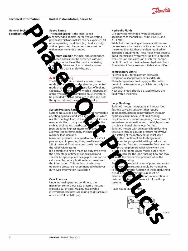
Technical Information Radial Piston Motors Series 60
5369264 bull Rev BA bull Sep 201314
Series 60 Motors run in freewheeling mode with almost no losses The necessary valving needs to be added into the circuit The schematic below shows a solution closed circuit operation
The following has to be provided y The high pressure ports of the motor are
connected to the tank y A low pressure is applied to the motor drain
port (Fig 8)which pushes the pistons into their cylinders (Fig9) disengaging them from the cam The necessary case pressure is shown on table 4
General Technical Specifications (Continued)
Freewheeling Option
Speed Pick-Up
Shock Load
Table 4 Max speeds in freewheeling condition
Case pressure 15 bar (22 psi)above ports A and B Dimension
Frame Size0470 0780 1048 1750
Freewheeling Output Speed max min-1 (RPM) 770 630 560 450
Figure 8 Circuit Diagramm Figure 9 Motor Section View Fig 10 Circuit DiagrammFreewheeling Option Freewheeling mode Two Speed Option
P001 440 P001 441 P001 449
B
L1
A
x1
L2
Two Speed OptionThe Two Speed Option is available on all motor sizes allowing increased application flexibility The integral displacement change valve selects half displacement When the displacement change port ldquox1rdquo (Fig 10) is connected to tank or motor case pressure maximum displacement is selected
When a signal pressure min 10 bar ( 145 psi) above case pressure [max 50 bar ( 725 psi)] is connected to ldquox1rdquo minimum displacement is selected Motor performance and life is optimal in the preferred direction of rotation (see Dimensions) The displacement should be changed while the motor is stationary This avoids sudden or unexpected speed changes and possible transmission damage
Series 60 Motors speed pick-up (Hall Effect Sensor) is especially designed for rough outdoor mobile or heavy industrial applications where speed monitoring revolution counting speed limit control or alarm function is required with no physical contact with the sensed motor shaft
Pin 1 Supply voltage = 45 to 16 V dc Supply current At 5 V -16 mA Pin 2 Not usedPin 3 Output digital open collector NPN Pin 4 Ground For installation and connector details see Fig 28 page 23
Table 5 Pulse Frequency
Motor Frame Size 0470 0780 1048 1750Pulses per revolution 78 92 101 121
Motors are designed for 20 g external accelleration
Phased Out Products
Technical Information Radial Piston Motors Series 60
369264 bull Rev BA bull Sep 2013 15
Figure 11 shows the volumetric mechanical and overall efficiencies of a typical Series 60 single and two speed motor at full displacement and system pressures of 200 bar (2900 psi) and 400 bar (5800 psi) with a fluid viscosity of 20 mm2s (98 SUS) at a temperature of 60 degC (140 degF)
Figure 12 shows the overall efficiency of a typical Series 60 single and two speed motor at full displacement with system pressure up to 480 bar (7000 psi) with a fluid viscosity of 20mm2s ( 98 SUS) at a temperature of 60 degC (140 degF)
General Technical Specifications (Continued)
Efficiency Graphs and Maps
Figure 11 Volumetric Mechanical and Overall Efficiency
Figure 12 Overall Efficiency
P001 392ESpeed of rated speed
Eci
ency
0 25 50 75 100
74
76
78
80
82
84
86
88
90
92
94
96
98
100
ηt = 400 bar (5800 psi)
Overall Eciencyηt = 200 bar (2900 psi)
Volumetric Eciencyηv = 200 bar (2900 psi)
ηm= 400 bar (5800 psi)
ηv = 400 bar (5800 psi)
Mechanical Eciency ηm = 200 bar (2900 psi)
Speed of rated speed
0
Syst
em p
ress
ure
∆p
bar (
psi)
25 75 100
85
8992
94
95
80
500
480 (7000)
300 (4350)
200 (2900)
100 (1450)
400 (5800)
500 (7250)
P001 394E
Phased Out Products
Technical Information Radial Piston Motors Series 60
5369264 bull Rev BA bull Sep 201316
Figure 13 shows the volumetric mechanical and overall efficiencies of a typical Series 60 single and two speed motor at half displacement in the preferred direction and system pressures of 200 bar (2900 psi) and 400 bar (5800 psi) with a fluid viscosity of 20 mm2s ( 98 SUS) at a temperature of 60deg C (140deg F)
Figure 14 shows the overall efficiency of a typical Series 60 single and two speed motor at half displacement in the preferred direction and system pressure up to 480 bar (7000) psi) with a fluid viscosity of 20 mm2s ( 98 SUS) at a temperature of 60 degC (140 deg F)
General Technical Specifications (Continued)
Efficiency Graphs and Maps
Figure 13 Volumetric Mechanical and Overall Efficiency at half displacement in the preferred direction
Figure 14 Overall Efficiency at half displacement in the preferred direction
P001 393 E
Speed of rated speed
Eci
ency
ηm= 200 bar (2900 psi)
0 25 50 75 100
65
70
75
80
85
90
95
100Volumetric Eciency ηv = 200 bar (2900 psi)
Mech Eciencyηm= 400 bar (5800 psi)
Overall Eciency ηt = 200 bar (2900 psi)
ηv = 400 bar (5800 psi)
ηt = 400 bar (5800 psi)
0 25 50 75
Speed of rated speed
78 84
88
9091
92
Syst
em p
ress
ure
∆p
bar (
psi)
500 (7250)
300 (4350)
200 (2900 )
100 (1450)
0
400 (5800)
480 (7000)
100P001 402 E
Phased Out Products
Technical Information Radial Piston Motors Series 60
369264 bull Rev BA bull Sep 2013 17
Dimensions60M0470 60V0470
Figure 15 Wheel Motor 60M0470 Single Speed VersionWheel Motor 60V0470 Two Speed Version
View X
TwoSpeed
L1A
B
300
(11
8)
81(319)
2020
2010
R 175R (069)
Purge Pressure Relief Valve
Case Drain Ports L1 + L2
degdeg
degdeg
Loop Flushing Shuttle Valve
L2
x1
265
(10
43)
175 +025-010
(689) +01 -004
30deg
for Speed Pick Up9 16-18UNF-2Binclined 15 degoptional
oslash05 Aoslash(02 ) A
80(315)
77(303)
94(37)
225(886)
P001 426E
oslash92
8-0
2(D
ia 3
65
-01
)
DisplacementChange Port X1716-20UNF-2B
Main Ports A + B 1 116-12UNF-2B
Studs 10x36 deg M14x15
13(51)
36(142)
6(24)
oslash14
0(D
ia 5
51)
oslash17
5(D
ia 6
89)
oslash22
3(D
ia 8
78)
Case Drain Port L1 34-16UNF-2B10deg inclined
64( L1L2 )(252)
54 (213)
7(28)
425 (167)
MountingSurface for Brake (Option)
Purge Pressure Relief Valve
312(123)
15 (59)
180(709)
oslash22
4-0
2(D
ia 8
82
-01
)
80 (32
)
67 (264)
90 (35
4)
82 (323)
505(199)
96(38)
TwoSpeed
A
10(4)
X
Single Speed MotorPortFlow
Rotation in outLH(CCW) B ARH (CW) A B
Two Speed MotorPref Rotation Right
Rotation in outLH(CCW) A BRH (CW) B A
Two Speed MotorPref Rotation Left
Rotation in outLH(CCW) B ARH (CW) A B
Rotation Radial Load Curve
P001 425E
Distance from Hub Mounting Face mm (in)
-4 -2 0 2 6-6-79 4 8 99
-200 -100 -50 0 50 100 150 200-150 250
Max
Rad
ial L
oad
kN (
lb)
0
20
40
60
4500
9000
0
13 500
18 000 80
Dynamic loadat DierentialPressure250 bar (3600 psi)
Phased Out Products
Technical Information Radial Piston Motors Series 60
5369264 bull Rev BA bull Sep 201318
Dimensions60M0470 60V0470
Figure 16 Flange Motor 60M0470 Single Speed VersionFlange Motor 60V0470 Two Speed Version
Single Speed MotorPortFlow
Rotation in outLH(CCW) B ARH (CW) A B
Two Speed MotorPref Rotation Right
Rotation in outLH(CCW) A BRH (CW) B A
Two Speed MotorPref Rotation Left
Rotation in outLH(CCW) B ARH (CW) A B
View X
X
P001 427E
TwoSpeed
L1A
B
300
(11
8)
81(319)
2020
2010
R 175R (069)
Purge Pressure Relief Valve
Case Drain Ports L1 + L2
degdeg
degdeg
Loop Flushing Shuttle Valve
L2
x1
265
(10
43)
175 +025-010
(689) +01 -004
30deg
for Speed Pick Up9 16-18UNF-2Binclined 15 degoptional
oslash05 Aoslash(02 ) A
80(315)
77(303)
94(37)
225(886)
P001 426E
Rotation Radial Load Curve
Dynamic loadat DierentialPressure250 bar (3600 psi)
Distance from Hub Mounting Face mm (in)
-4 -2 0 2 6-6-79 4 8 99
-200 -100 -50 0 50 100 150 200-150 250
Max
Rad
ial L
oad
kN (
lb)
0
20
40
60
4500
9000
13 500
0
oslash92
8-0
2(D
ia 3
65
-01
)
DisplacementChange Port X1716-20UNF-2B
Main Ports A + B 1 116-12UNF-2B25deg inclined
Studs 5x72 deg M14x15
12(47)
37(146)
6(24)
oslash14
0(D
ia 5
51)
oslash17
5(D
ia 6
89)
oslash22
3(D
ia 8
78)
Case Drain Ports L1 34-16UNF-2B10deg inclined
64( L1L2 )(252)
25 (98)
7(28)
425 (167)
MountingSurface for Brake (Option)
Purge Pressure Relief Valve
280(110)
15 (59)147(579)
oslash22
4-0
2(D
ia 8
82
-01
)
80 (32
)
67 (264)90 (3
54)
82 (323)
505(199)
96(38)
Two Speed
A
10(4)
Phased Out Products
Technical Information Radial Piston Motors Series 60
369264 bull Rev BA bull Sep 2013 19
Dimensions60M0470 60V0470
Figure 17 Shaft Motor 60M0470 Single Speed VersionShaft Motor 60V0470 Two Speed Version
Single Speed MotorPortFlow
Rotation in outLH(CCW) B ARH (CW) A B
Two Speed MotorPref Rotation Right
Rotation in outLH(CCW) A BRH (CW) B A
Two Speed MotorPref Rotation Left
Rotation in outLH(CCW) B ARH (CW) A B
View X
P001 428E
TwoSpeed
L1A
B
300
(11
8)
81(319)
2020
2010
R 175R (069)
Purge Pressure Relief Valve
Case Drain Ports L1 + L2
degdeg
degdeg
Loop Flushing Shuttle Valve
L2
x1
265
(10
43)
175 +025-010
(689) +01 -004
30deg
for Speed Pick Up9 16-18UNF-2Binclined 15 degoptional
oslash05 Aoslash(02 ) A
80(315)
77(303)
94(37)
225(886)
X
P001 426E
Rotation
Max Radial Load
DisplacementChange Port X1716-20UNF-2B
Main Ports A + B 1 116-12UNF-2B25deg inclined
Case Drain Port L1 34-16UNF-2B10deg inclined
395 (156)
18 ( L1L2 )(7)
MountingSurface for Brake (Option)
Purge Pressure Relief Valve
oslash22
3(D
ia 8
78)
80 (32
)
15 (59)
90 (35
4)
315 (124)
Two Speed
23(91)10 (39)
oslash20
0-0
07
(Dia
787
4-0
03)
312(123)
203 (799)
39(154)
54 (213)
38-
16U
NC
x15
(59)
full
THD
254
(10
)
34(134)
R25 +02(R10 +01 )
87 (343)
47(185)
Shaft Spline Data5 ssalC a1129B ISNA Spline standard
Spline Fit Pitch D
03 elgnA erusserPNo of teethSplineMajor Dia
A
-50 -40 -30 -20 -10 0
-2 -1
50
60
30
40
20
0
10
Allo
wab
lera
dial
Loa
d kN
(lb
)
Distance from Shaftshoulder mm (in)
0
2250
6750
9000
11250
4500
13500
0
Dynamic loadat ∆p = 250 bar (3600 psi)
Flat Root Side Fit4863 (1916)
231224508 (20)
Phased Out Products
Technical Information Radial Piston Motors Series 60
5369264 bull Rev BA bull Sep 201320
Dimensions60M0780 60V780
Figure 18 Wheel Motor 60M0780 Single Speed VersionWheel Motor 60V0780 TwoSpeed Version
Single Speed MotorPortFlow
Rotation in outLH(CCW) B ARH (CW) A B
Two Speed MotorPref Rotation Right
Rotation in outLH(CCW) A BRH (CW) B A
Two Speed MotorPref Rotation Left
Rotation in outLH(CCW) B ARH (CW) A B
20
40
60
80
0
4500
9000
13 500
18 000
Max
Rad
ial L
oad
kN (
lb)
Dynamic load atDierential Pressure250 bar (3600 psi)
Distance from Hub Mounting Face mm (in)
-200 -150 -100 -50 0 50 100 150 200 250
-79 -6 -4 -2 0 2 4 6 8 98
oslash16
08
-02
(Dia
63
3 -0
1)
DisplacementChange Port X1716-20UNF-2B
Main Ports A + B 1 116-12UNF-2B25deg inclined
Studs 6x60 deg M18x15
15(6)
36(142)
8(31)
oslash20
5(D
ia 8
1)
oslash24
7(D
ia 9
7)
oslash26
6(D
ia 1
05)
Case Drain Port L134-16UNF-2B10deg inclined
70( L1L2 ) (276)
58 (228)
7(28)
44 (173)
MountingSurface for Brake (Option)
Purge Pressure Relief Valve
334(123)
17 (7)
195(768)
oslash25
3-0
2(D
ia 9
96
-01
)96 (38
)
72 (283)
106
(42
)
88 (35)
51(201)
104(409)
A
TwoSpeed
17(7)
View X
for Speed Pick Up9 16-18UNF-2Binclined 15 degoptional
L2L1A
B
335
(13
2)
267(1051)
R 175R (069)
Purge Pressure Relief Valve
Case Drain Ports L1 + L2
Loop Flushing Shuttle Valve
x1
TwoSpeed
300
(11
81)
175 +025-010
(689) +01 -004
oslash05 Aoslash(02 ) A
30deg
15deg15deg
15deg15deg
96(38)
93(37)
91(36)
109(43)
P001 435E
P001 436E
Rotation Radial Load Curve
X
Phased Out Products
Technical Information Radial Piston Motors Series 60
369264 bull Rev BA bull Sep 2013 21
Dimensions60M0780 60 V780
Figure 19 Flange Motor 60M0780 Single Speed VersionFlange Motor 60V0780 Two Speed Version
Single Speed MotorPortFlow
Rotation in outLH(CCW) B ARH (CW) A B
Two Speed MotorPref Rotation Right
Rotation in outLH(CCW) A BRH (CW) B A
Two Speed MotorPref Rotation Left
Rotation in outLH(CCW) B ARH (CW) A B
View X
X
Max
Rad
ial L
oad
kN (
lb)
0
20
40
60
4500
9000
13 500
0
8018 000
Distance from Hub Mounting Face mm (in)
-4 -2 0 2 6-6-79 4 8 99
-200 -100 -50 0 50 100 150 200-150 250
Dynamic loadat DierentialPressure250 bar (3600 psi)
72 (283)
DisplacementChange Port X1716-20UNF-2B
Main Ports A + B 1 116-12UNF-2B25deg inclined
Case Drain Port L134-16UNF-2B
10deg inclined
70( L1L2 )(276)
27 (106)
7(28)
44 (173)
MountingSurface for Brake (Option)
304(119)
17 (7)
25(10)
oslash25
3-0
2(D
ia 9
96
-01
)
96 (38
)
106
(42
)
88 (35)
51(201)
104(409)
Two Speed
A
oslash16
08
-02
(Dia
63
3 -0
1)
Studs 6x60 deg M18x15
15(6)
36(142)
7(3)
oslash20
5(D
ia 8
1)
oslash24
7(D
ia 9
7)
oslash26
6(D
ia 1
05)
Purge Pressure Relief Valve
164(65)
for Speed Pick Up9 16-18UNF-2Binclined 15 degoptional
L2L1A
B
335
(13
2)
267(1051)
R 175R (069)
Purge Pressure Relief Valve
Case Drain Ports L1 + L2
Loop Flushing Shuttle Valve
x1
TwoSpeed
300
(11
81)
175 +025-010
(689) +01 -004
oslash05 Aoslash(02 ) A
30deg
15deg15deg
15deg15deg
96(38)
93(37)
91(36)
109(43)
P001 436E
P001 437E
Rotation Radial Load Curve
Phased Out Products
Technical Information Radial Piston Motors Series 60
5369264 bull Rev BA bull Sep 201322
Dimensions60M0780 60V780
Figure 20 Shaft Motor 60M0780 Single Speed VersionShaft Motor 60V0780 Two Speed Version
Single Speed MotorPortFlow
Rotation in outLH(CCW) B ARH (CW) A B
Two Speed MotorPref Rotation Right
Rotation in outLH(CCW) A BRH (CW) B A
Two Speed MotorPref Rotation Left
Rotation in outLH(CCW) B ARH (CW) A B
View X
for Speed Pick Up9 16-18UNF-2Binclined 15 degoptional
L2L1A
B
335
(13
2)
267(1051)
R 175R (069)
Purge Pressure Relief Valve
Case Drain Ports L1 + L2
Loop Flushing Shuttle Valve
x1
TwoSpeed
300
(11
81)
175 +025-010
(689) +01 -004
oslash05 Aoslash(02 ) A
30deg
15deg15deg
15deg15deg
96(38)
93(37)
91(36)
109(43)
X
P001 436E
Rotation
Max Radial Load
DisplacementChange Port X1716-20UNF-2B
Main Ports A + B1 116-12UNF-2B25deg inclined
Case Drain Port L134-16UNF-2B10deg inclined
44 (173)
18 ( L1L2 ) (71)
MountingSurface for Brake (Option)
Purge Pressure Relief Valve
oslash26
7(D
ia 1
051
)96 (38
)
16 (63)
106
(42
)
37 (146)
Two Speed
25(98)16 (63)
oslash22
4-0
15
(Dia
88
19-0
06)
343(1350)
215 (846)
40(157)
70 (276)
38-
16 U
NC
x15
(59)
full
THD
381
(15
)
46(181)
R3 +02(R12 +01 )
97 (382)
54(213)
A
-100 -80 -60 -40 -20 0
-4 -2
100
60
80
40
0
20
Allo
wab
lera
dial
Loa
d kN
(lb)
Distance from Shaftshoulder mm (in)
0
9000
13500
4500
18000
0
22500
P001 438E
Dynamic load at∆p = 250 bar (3600 psi)
Shaft Spline Data5 ssalC a1129B ISNA Spline standard
Spline Fit Pitch D
03 elgnA erusserPNo of teethSplineMajor Dia
Flat Root Side Fit635 (25)
208166667 (2625)
Phased Out Products
Technical Information Radial Piston Motors Series 60
369264 bull Rev BA bull Sep 2013 23
Dimensions60M1048 60V1048
Figure 21 Wheel Motor 60M1048 Single Speed VersionWheel Motor 60V0470 Two Speed Version
Single Speed MotorPortFlow
Rotation in outLH(CCW) B ARH (CW) A B
Two Speed MotorPref Rotation Right
Rotation in outLH(CCW) A BRH (CW) B A
Two Speed MotorPref Rotation Left
Rotation in outLH(CCW) B ARH (CW) A B
View X
P001 414E
X
P001 415E
295(1161)
x110
degdeg
L1A
B
R 20 R (079)
108(425)
108(425)
Purge Pressure Relief Valve Loop Flushing Shuttle Valve
L2
TwoSpeed37
5 (1
476
)
2020
20
Case Drain Ports L1 + L2
degdeg
335
(13
19)
225 +025-010
(89) +01 -004
30deg
for Speed Pick Up9 16-18UNF-2Binclined 15 degoptional
oslash075oslash(03 )
AA
118(465)
Rotation Radial Load Curve
20
40
60
80
100
0
4500
9000
13 500
18 000
22 500
Max
Rad
ial L
oad
kN (
lb)
Distance from Hub Mounting Face mm (in)
-200 -150 -100 -50 0 50 100 150 200 250
-79 -6 -4 -2 0 2 4 6 8 98
Dynamic load atDierentialPressure250 bar (3600 psi)
Studs 5x72 deg M22x15
Case Drain Ports L1 + L2 34-16UNF-2B
66( L2 ) (260)
565(222)
Main Ports A + B 075-Code 62Split Flange Boss per SAE J 51838-16UNC-2B 22 (088) min full thread depth
8 (31)
48 (189)
MountingSurface for Brake (Option)
16(63)
47(185)
Purge Pressure Relief Valve
112(441)
379(1492)
19 (75)
220(866)
8 (31)
oslash17
58
-02
(Dia
69
2 -0
1)
oslash22
5(D
ia 8
86)
280
(Dia
11
02)oslash
292
(Dia
115
0)
508
(20
0)
285
-02
(11
22-0
1)
96 (37
8)
DisplacementChange Port X1716-20UNF-2B
79 (31)
115
(45
3)
Two Speed
96 (378)
238(94)
81( L1 )(319)
24(9)
A
Phased Out Products
Technical Information Radial Piston Motors Series 60
5369264 bull Rev BA bull Sep 201324
Dimensions60M1048 60V1048
Figure 22 Flange Motor 60M1048 Single Speed VersionFlange Motor 60V1048 Two Speed Version
Single Speed MotorPortFlow
Rotation in outLH(CCW) B ARH (CW) A B
Two Speed MotorPref Rotation Right
Rotation in outLH(CCW) A BRH (CW) B A
Two Speed MotorPref Rotation Left
Rotation in outLH(CCW) B ARH (CW) A B
View X
X
295(1161)
x1
10deg
deg
L1A
B
R 20 R (079)
108(425)
108(425)
Purge Pressure Relief Valve Loop Flushing Shuttle Valve
L2
TwoSpeed37
5 (1
476
)
2020
20
Case Drain Ports L1 + L2
degdeg
335
(13
19)
225 +025-010
(89) +01 -004
30deg
for Speed Pick Up9 16-18UNF-2Binclined 15 degoptional
oslash075oslash(03 )
AA
118(465)
Dynamic loadat DierentialPressure250 bar (3600 psi)
Max
Rad
ial L
oad
kN (
lb)
0
20
40
60
4500
9000
13 500
0
Distance from Hub Mounting Face mm (in)
-4 -2 0 2 6-6-79 4 8 99
-200 -100 -50 0 50 100 150 200-150 250
Studs 6x60 deg M18x15
Case Drain Ports L1 + L2 34-16UNF-2B
66( L2 ) (26)
255(100)
Main Ports A + B 075-Code 62Split Flange Boss per SAE J 51838-16UNC-2B 22 (088) min full thread depth
8(31)
48 (189)
MountingSurface for Brake (Option)
15(59)
36(142)
Purge Pressure Relief Valve
112(441)
322(127)
19 (75)
1745(687)
6(24)
oslash16
08
-02
(Dia
63
3 -0
1)
oslash20
5 (D
ia 8
07)
250
(Dia
98
4)
oslash29
2(D
ia11
50)
508
(20
)
285
-02
(11
22-0
1)
96 (37
8)
DisplacementChange Port X1716-20UNF-2B
79 (311)11
5 (4
53)
Two Speed
96 (378)
238(94)
81( L1 )(319)
A
255 (10)
P001 415E
Rotation Radial Load Curve
P001 416E
Phased Out Products
Technical Information Radial Piston Motors Series 60
369264 bull Rev BA bull Sep 2013 25
Dimensions60M1048 60V1048
Figure 23 Shaft Motor 60M1048 Single Speed VersionShaft Motor 60M1048 Two Speed Version
Single Speed MotorPortFlow
Rotation in outLH(CCW) B ARH (CW) A B
Two Speed MotorPref Rotation Right
Rotation in outLH(CCW) A BRH (CW) B A
Two Speed MotorPref Rotation Left
Rotation in outLH(CCW) B ARH (CW) A B
View X
295(1161)
x110
degdeg
L1A
B
R 20 R (079)
108(425)
108(425)
Purge Pressure Relief Valve Loop Flushing Shuttle Valve
L2
TwoSpeed37
5 (1
476
)
2020
20
Case Drain Ports L1 + L2
degdeg
335
(13
19)
225 +025-010
(89) +01 -004
30deg
for Speed Pick Up9 16-18UNF-2Binclined 15 degoptional
oslash075oslash(03 )
AA
118(465)
P001 415E
Rotation
Max Radial Load
X
73 ( L1 )(287)
28(110)13 (51)
oslash28
0-0
15
(Dia
110
24-0
06)
372(146)
2325 (915)
50 (197)
70 (276)
38-
16U
NC
15 (
59) f
ull T
HD
381
(15
)
46(181)
123 (484)
R 3 +02(R12 +01 )
515 (203)
Main Ports A + B 075-Code 62Split Flange Boss per SAE J 51838-16UNC-2B22 (088) min full thread depth
Case Drain Ports L1+L234-16UNF-2B
40 (157)
MountingSurface for Brake (Option)
104(41)
238(94)
508
(20
0)
oslash29
2(D
ia11
5)96 (37
8)
DisplacementChange Port X1716-20UNF-2B
17(67)
115
(45
3)
Two Speed
58( L2 )(228)
PurgePressureRelief ValveA
-100 -80 -60 -40 -20 0
-4 -2
120
60
80
40
0
20
Allo
wab
lera
dial
Loa
d kN
(lb)
Distance from Shaftshoulder mm (in)
0
9000
13500
4500
18000
0
22500 10027000
P001 417E
Dynamic load at ∆p = 250 bar (3600 psi)
Shaft Spline Data5 ssalC a1129B ISNA Spline standard
Spline Fit Pitch Dia
03 elgnA erusserPNo of teethSplineMajor Dia
Flat Root Side Fit73025 (30)
23816762 (30)
Phased Out Products
Technical Information Radial Piston Motors Series 60
5369264 bull Rev BA bull Sep 201326
Dimensions60M1750 60V1750
Figure 24 Wheel Motor 60M1750 Single Speed VersionWheel Motor 60V1750 Two Speed Version
Single Speed MotorPortFlow
Rotation in outLH(CCW) B ARH (CW) A B
Two Speed MotorPref Rotation Right
Rotation in outLH(CCW) A BRH (CW) B A
Two Speed MotorPref Rotation Left
Rotation in outLH(CCW) B ARH (CW) A B
View X
X
Rotation Radial Load Curve
P001 430E
P001 429E
L2L1A
B
425
(16
73)
Purge Pressure Relief Valve
Case Drain Ports L1 + L2
Loop Flushing Shuttle Valve
x1
Two Speed
385
(15
16)
225 +025-010
(89) +01 -004
oslash075 Aoslash(03 ) A
30deg
for Speed Pick Up9 16-18UNF-2Binclined 15 degoptional
15deg15deg
15deg15deg
350(1378)
R 20 R (079)
124(488)
124(488)
138(543)
Dynamic load atDierentialPressure250 bar (3600 psi)
(in)Distance from Hub Mounting Face mm
-200 -150 -100 -50 0 50 100 150 200 250
-79 -6 -4 -2 0 2 4 6 8 98
Max
Rad
ial L
oad
kN (
lb)
20
40
140
160
60
80
100
120
180
0
4500
9000
13 500
27 000
36 000
18 000
22 500
31 500
40 500
0
Studs 10x36 deg M22x15
Case Drain Ports L1 + L2 78-14UNF-2B
69(272)
Main Ports A + B 100-Code 62Split Flange Boss per SAE J 518716-14UNC-2B 27 (106) min full thread depth
11(43)
66 (2598)
MountingSurface for Brake (Option)
16(63)
47(185)
Purge Pressure Relief Valve
132(520)
433(1705)
225 (886)
254(100)
8 (31)
oslash17
58
-02
(Dia
69
2 -0
1)
oslash22
5(D
ia 8
86)
280
(Dia
11
02)oslash
350
(Dia
137
8)
571
5(2
25)
oslash33
0-0
2(D
ia12
992
-008
)
115
(45
28)
DisplacementChange Port X1716-20UNF-2B
99 (390)
141
(55
5)
Two Speed
116 (4567)
2776(1093)
96( L1L2 )(378)
20(0787)
A
Phased Out Products
Technical Information Radial Piston Motors Series 60
369264 bull Rev BA bull Sep 2013 27
Dimensions60M1750 60V1750
Figure 25 Flange Motor 60M1750 Single Speed VersionFlange Motor 60V1750 Two Speed Version
Single Speed MotorPortFlow
Rotation in outLH(CCW) B ARH (CW) A B
Two Speed MotorPref Rotation Right
Rotation in outLH(CCW) A BRH (CW) B A
Two Speed MotorPref Rotation Left
Rotation in outLH(CCW) B ARH (CW) A B
View X
X
P001 430E
Rotation Radial Load Curve
P001 431E
L2L1A
B
425
(16
73)
Purge Pressure Relief Valve
Case Drain Ports L1 + L2
Loop Flushing Shuttle Valve
x1
Two Speed
385
(15
16)
225 +025-010
(89) +01 -004
oslash075 Aoslash(03 ) A
30deg
for Speed Pick Up9 16-18UNF-2Binclined 15 degoptional
15deg15deg
15deg15deg
350(1378)
R 20 R (079)
124(488)
124(488)
138(543)
0
Dynamic loadat DierentialPressure250 bar (3600 psi)
Distance from Hub Mounting Face mm (in)
-6 -4 -2 0 2 64 8 99-79
-200 -100 -50 0 50 100 150 200-150 250
Max
Rad
ial L
oad
kN (
lb)
0
20
40
60
4500
9000
13 500
8018 000
10022 500
12027 000
14031 500
16036 000
18040 500
Studs 10x36 deg M22x15
Case Drain Ports L1 + L2 78-14UNF-2B
32(126)
Main Ports A + B 100-Code 62Split Flange Boss per SAE J 518716-14UNC-2B 27 (106) min full thread depth
11(43)
66 (2598)
MountingSurface for Brake (Option)
16(63)
47(185)
Purge Pressure Relief Valve
132(520)
389(1531)
225 (886)
210(1827)
8 (31)
oslash17
58
-02
(Dia
69
2 -0
1)
oslash22
5(D
ia 8
86)
280
(Dia
11
02)oslash
350
(Dia
137
8)
571
5(2
25)
oslash33
0-0
2(D
ia 1
299
2-0
08)
115
(45
28)
DisplacementChange Port X1716-20UNF-2B
99 (390)
141
(55
5)
Two Speed
116 (4567)
2776(1093)
96( L1 L2 )(378)
29 (114)
A
Phased Out Products
Technical Information Radial Piston Motors Series 60
5369264 bull Rev BA bull Sep 201328
Dimensions60M1750 60V1750
Figure 26 Shaft Motor 60M1750 Single Speed VersionShaft Motor 60V1750 Two Speed Version
Single Speed MotorPortFlow
Rotation in outLH(CCW) B ARH (CW) A B
Two Speed MotorPref Rotation Right
Rotation in outLH(CCW) A BRH (CW) B A
Two Speed MotorPref Rotation Left
Rotation in outLH(CCW) B ARH (CW) A B
View X
L2L1A
B
425
(16
73)
Purge Pressure Relief Valve
Case Drain Ports L1 + L2
Loop Flushing Shuttle Valve
x1
Two Speed
385
(15
16)
225 +025-010
(89) +01 -004
oslash075 Aoslash(03 ) A
30deg
for Speed Pick Up9 16-18UNF-2Binclined 15 degoptional
15deg15deg
15deg15deg
350(1378)
R 20 R (079)
124(488)
124(488)
138(543)
P001 430E
Rotation
X
Max Radial Load
Displacementchange Port X1716-20UNF-2B
24(94)15 (59)
oslash31
5-0
15
(Dia
124
02-0
06)
440(173)
2835 (1116)
48 (189)
90 (354)
12-
13 U
NC
X22
(86)
full
THD
381
(15
)
63(248)
141 (555)
R4 +02(R16 +01 )
97 (382)
Main Ports A + B 100-Code 62Split Flange Boss per SAE J 518716-14UNC-2B27 (106) min full thread depth
Case Drain Ports L1+L278-20UNF-2B
20 (079) ( L1+L2 )
50 (197)
MountingSurface for Brake (Option)Purge Pressure
Relief Valve
121 (48)
278(109)
572
(22
5)
oslash33
0(D
ia12
99)11
5 (4
53)
17 (67)
141
(55
5)
Two Speed
9 (35)
oslash35
0(D
ia13
78)
A
-100 -80 -60 -40 -20 0
-4 -2
200
100
150
0
50
Allo
wab
lera
dial
Loa
d kN
(lb)
Distance from Shaftshoulder mm (in)
0
22500
11250
33750
0
45000
P001 432E
Dynamic load at ∆p = 250 bar (3600 psi)
Shaft Spline Data5 ssalC a1129B ISNA Spline standard
Spline Fit Pitch Dia
03 elgnA erusserPNo of teethSplineMajor Dia
Flat Root Side Fit889 (35)
288169207 (3625)
Phased Out Products
Technical Information Radial Piston Motors Series 60
369264 bull Rev BA bull Sep 2013 29
NotesPhased Out Products
Technical Information Radial Piston Motors Series 60
5369264 bull Rev BA bull Sep 201330
DimensionsBrakes
Figure 27 Radial Piston Motor with Brake (0ptional)
P001 418E
Table 6 Brake Dimensions
Series Dimension
A B C
60M0470 23 (090) 74 (290) oslash212 (Dia 835)
60M0780 42 (165) 100 (394) oslash245 (Dia 965)
60M1048 30 (118) 90 (354) oslash280 (Dia 1102)
60M1750 38 (147) 107 (421) oslash320 (Dia 1260)
B
CX7
MountingFace
Mechanical BrakeRelease 1 to be used with Mech Brake Release 2
Mechanical BrakeRelease 2to be used with Mech Brake Release 1
A
Hydraulic BrakeRelease X7916-18UNF-2B
Mechanical BrakeRelease 1 to be used with Mech Brake Release 2
Mechanical BrakeRelease 2to be used with Mech Brake Release 1
TwoSpeed
X
View X
Phased Out Products
Technical Information Radial Piston Motors Series 60
369264 bull Rev BA bull Sep 2013 31
DimensionsSpeed Sensor
Figure 28 Radial Piston Motor with Speed Sensor (0ptional)
Section A - A (11)Speed Sensor
Connecto IdNoStraightRight angle
Connector is not supplied with the motorPlease order separatly using above Id No
Table 7 Speed Sensor Connector
Electrical details see page12
P001 444E
A
A
30deg 15 deg
31m
ax (1
22)
Pin 1Pin 2
Pin 3
Pin 4
Key Way
Wrench-Flats
Connector Insert
View Y
Y
127
(50)
500724500725
Phased Out Products
Comatrolwwwcomatrolcom
Schwarzmuumlller-Inverterwwwschwarzmueller-invertercom
Turolla wwwturollaocgcom
Valmovawwwvalmovacom
Hydro-Gear wwwhydro-gearcom
Daikin-Sauer-Danfosswwwdaikin-sauer-danfosscom
Danfoss Power Solutions is a global manufacturer and supplier of high-quality hydraulic and electronic components We specialize in providing state-of-the-art technology and solutions that excel in the harsh operating conditions of the mobile off -highway market Building on our extensive applications expertise we work closely with our customers to ensure exceptional performance for a broad range of off -highway vehicles
We help OEMs around the world speed up system development reduce costs and bring vehicles to market faster Danfoss ndash Your Strongest Partner in Mobile Hydraulics
Go to wwwpowersolutionsdanfosscom for further product information
Wherever off -highway vehicles are at work so is Danfoss
We off er expert worldwide support for our customers ensuring the best possible solutions for outstanding performance And with an extensive network of Global Service Partners we also provide comprehensive global service for all of our components
Please contact the Danfoss Power Solution representative nearest you
Products we off er
Bent Axis Motors
Closed Circuit Axial Piston Pumps and Motors
Displays
Electrohydraulic Power Steering
Electrohydraulics
Hydraulic Power Steering
Integrated Systems
Joysticks and Control Handles
Microcontrollers and Software
Open Circuit Axial Piston Pumps
Orbital Motors
PLUS+1reg GUIDE
Proportional Valves
Sensors
Steering
Transit Mixer Drives
Local address
Danfoss can accept no responsibility for possible errors in catalogues brochures and other printed material Danfoss reserves the right to alter its products without notice This also applies to products already on order provided that such alterations can be made without subsequential changes being necessary in specifications already agreedAll trademarks in this material are property of the respective companies Danfoss and the Danfoss logotype are trademarks of Danfoss AS All rights reserved
Danfoss Power Solutions22F Block C Yishan RdShanghai 200233 ChinaPhone +86 21 3418 5200
Danfoss Power Solutions GmbH amp Co OHGKrokamp 35D-24539 Neumuumlnster GermanyPhone +49 4321 871 0
Danfoss Power Solutions ApSNordborgvej 81DK-6430 Nordborg DenmarkPhone +45 7488 2222
Danfoss Power Solutions US Company2800 East 13th StreetAmes IA 50010 USAPhone +1 515 239 6000
369264 bull Rev BA bull Sep 2013 wwwdanfosscom copy Danfoss AS 2013-09
Phased Out Products
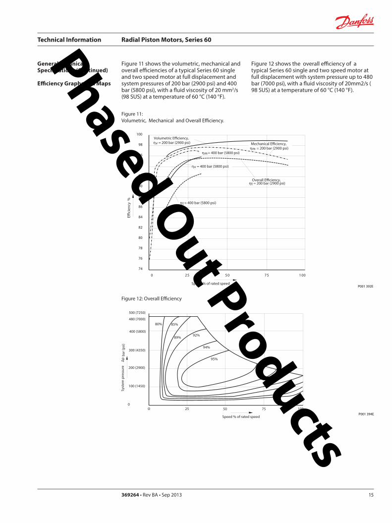
Technical Information Radial Piston Motors Series 60
5369264 bull Rev BA bull Sep 201316
Figure 13 shows the volumetric mechanical and overall efficiencies of a typical Series 60 single and two speed motor at half displacement in the preferred direction and system pressures of 200 bar (2900 psi) and 400 bar (5800 psi) with a fluid viscosity of 20 mm2s ( 98 SUS) at a temperature of 60deg C (140deg F)
Figure 14 shows the overall efficiency of a typical Series 60 single and two speed motor at half displacement in the preferred direction and system pressure up to 480 bar (7000) psi) with a fluid viscosity of 20 mm2s ( 98 SUS) at a temperature of 60 degC (140 deg F)
General Technical Specifications (Continued)
Efficiency Graphs and Maps
Figure 13 Volumetric Mechanical and Overall Efficiency at half displacement in the preferred direction
Figure 14 Overall Efficiency at half displacement in the preferred direction
P001 393 E
Speed of rated speed
Eci
ency
ηm= 200 bar (2900 psi)
0 25 50 75 100
65
70
75
80
85
90
95
100Volumetric Eciency ηv = 200 bar (2900 psi)
Mech Eciencyηm= 400 bar (5800 psi)
Overall Eciency ηt = 200 bar (2900 psi)
ηv = 400 bar (5800 psi)
ηt = 400 bar (5800 psi)
0 25 50 75
Speed of rated speed
78 84
88
9091
92
Syst
em p
ress
ure
∆p
bar (
psi)
500 (7250)
300 (4350)
200 (2900 )
100 (1450)
0
400 (5800)
480 (7000)
100P001 402 E
Phased Out Products
Technical Information Radial Piston Motors Series 60
369264 bull Rev BA bull Sep 2013 17
Dimensions60M0470 60V0470
Figure 15 Wheel Motor 60M0470 Single Speed VersionWheel Motor 60V0470 Two Speed Version
View X
TwoSpeed
L1A
B
300
(11
8)
81(319)
2020
2010
R 175R (069)
Purge Pressure Relief Valve
Case Drain Ports L1 + L2
degdeg
degdeg
Loop Flushing Shuttle Valve
L2
x1
265
(10
43)
175 +025-010
(689) +01 -004
30deg
for Speed Pick Up9 16-18UNF-2Binclined 15 degoptional
oslash05 Aoslash(02 ) A
80(315)
77(303)
94(37)
225(886)
P001 426E
oslash92
8-0
2(D
ia 3
65
-01
)
DisplacementChange Port X1716-20UNF-2B
Main Ports A + B 1 116-12UNF-2B
Studs 10x36 deg M14x15
13(51)
36(142)
6(24)
oslash14
0(D
ia 5
51)
oslash17
5(D
ia 6
89)
oslash22
3(D
ia 8
78)
Case Drain Port L1 34-16UNF-2B10deg inclined
64( L1L2 )(252)
54 (213)
7(28)
425 (167)
MountingSurface for Brake (Option)
Purge Pressure Relief Valve
312(123)
15 (59)
180(709)
oslash22
4-0
2(D
ia 8
82
-01
)
80 (32
)
67 (264)
90 (35
4)
82 (323)
505(199)
96(38)
TwoSpeed
A
10(4)
X
Single Speed MotorPortFlow
Rotation in outLH(CCW) B ARH (CW) A B
Two Speed MotorPref Rotation Right
Rotation in outLH(CCW) A BRH (CW) B A
Two Speed MotorPref Rotation Left
Rotation in outLH(CCW) B ARH (CW) A B
Rotation Radial Load Curve
P001 425E
Distance from Hub Mounting Face mm (in)
-4 -2 0 2 6-6-79 4 8 99
-200 -100 -50 0 50 100 150 200-150 250
Max
Rad
ial L
oad
kN (
lb)
0
20
40
60
4500
9000
0
13 500
18 000 80
Dynamic loadat DierentialPressure250 bar (3600 psi)
Phased Out Products
Technical Information Radial Piston Motors Series 60
5369264 bull Rev BA bull Sep 201318
Dimensions60M0470 60V0470
Figure 16 Flange Motor 60M0470 Single Speed VersionFlange Motor 60V0470 Two Speed Version
Single Speed MotorPortFlow
Rotation in outLH(CCW) B ARH (CW) A B
Two Speed MotorPref Rotation Right
Rotation in outLH(CCW) A BRH (CW) B A
Two Speed MotorPref Rotation Left
Rotation in outLH(CCW) B ARH (CW) A B
View X
X
P001 427E
TwoSpeed
L1A
B
300
(11
8)
81(319)
2020
2010
R 175R (069)
Purge Pressure Relief Valve
Case Drain Ports L1 + L2
degdeg
degdeg
Loop Flushing Shuttle Valve
L2
x1
265
(10
43)
175 +025-010
(689) +01 -004
30deg
for Speed Pick Up9 16-18UNF-2Binclined 15 degoptional
oslash05 Aoslash(02 ) A
80(315)
77(303)
94(37)
225(886)
P001 426E
Rotation Radial Load Curve
Dynamic loadat DierentialPressure250 bar (3600 psi)
Distance from Hub Mounting Face mm (in)
-4 -2 0 2 6-6-79 4 8 99
-200 -100 -50 0 50 100 150 200-150 250
Max
Rad
ial L
oad
kN (
lb)
0
20
40
60
4500
9000
13 500
0
oslash92
8-0
2(D
ia 3
65
-01
)
DisplacementChange Port X1716-20UNF-2B
Main Ports A + B 1 116-12UNF-2B25deg inclined
Studs 5x72 deg M14x15
12(47)
37(146)
6(24)
oslash14
0(D
ia 5
51)
oslash17
5(D
ia 6
89)
oslash22
3(D
ia 8
78)
Case Drain Ports L1 34-16UNF-2B10deg inclined
64( L1L2 )(252)
25 (98)
7(28)
425 (167)
MountingSurface for Brake (Option)
Purge Pressure Relief Valve
280(110)
15 (59)147(579)
oslash22
4-0
2(D
ia 8
82
-01
)
80 (32
)
67 (264)90 (3
54)
82 (323)
505(199)
96(38)
Two Speed
A
10(4)
Phased Out Products
Technical Information Radial Piston Motors Series 60
369264 bull Rev BA bull Sep 2013 19
Dimensions60M0470 60V0470
Figure 17 Shaft Motor 60M0470 Single Speed VersionShaft Motor 60V0470 Two Speed Version
Single Speed MotorPortFlow
Rotation in outLH(CCW) B ARH (CW) A B
Two Speed MotorPref Rotation Right
Rotation in outLH(CCW) A BRH (CW) B A
Two Speed MotorPref Rotation Left
Rotation in outLH(CCW) B ARH (CW) A B
View X
P001 428E
TwoSpeed
L1A
B
300
(11
8)
81(319)
2020
2010
R 175R (069)
Purge Pressure Relief Valve
Case Drain Ports L1 + L2
degdeg
degdeg
Loop Flushing Shuttle Valve
L2
x1
265
(10
43)
175 +025-010
(689) +01 -004
30deg
for Speed Pick Up9 16-18UNF-2Binclined 15 degoptional
oslash05 Aoslash(02 ) A
80(315)
77(303)
94(37)
225(886)
X
P001 426E
Rotation
Max Radial Load
DisplacementChange Port X1716-20UNF-2B
Main Ports A + B 1 116-12UNF-2B25deg inclined
Case Drain Port L1 34-16UNF-2B10deg inclined
395 (156)
18 ( L1L2 )(7)
MountingSurface for Brake (Option)
Purge Pressure Relief Valve
oslash22
3(D
ia 8
78)
80 (32
)
15 (59)
90 (35
4)
315 (124)
Two Speed
23(91)10 (39)
oslash20
0-0
07
(Dia
787
4-0
03)
312(123)
203 (799)
39(154)
54 (213)
38-
16U
NC
x15
(59)
full
THD
254
(10
)
34(134)
R25 +02(R10 +01 )
87 (343)
47(185)
Shaft Spline Data5 ssalC a1129B ISNA Spline standard
Spline Fit Pitch D
03 elgnA erusserPNo of teethSplineMajor Dia
A
-50 -40 -30 -20 -10 0
-2 -1
50
60
30
40
20
0
10
Allo
wab
lera
dial
Loa
d kN
(lb
)
Distance from Shaftshoulder mm (in)
0
2250
6750
9000
11250
4500
13500
0
Dynamic loadat ∆p = 250 bar (3600 psi)
Flat Root Side Fit4863 (1916)
231224508 (20)
Phased Out Products
Technical Information Radial Piston Motors Series 60
5369264 bull Rev BA bull Sep 201320
Dimensions60M0780 60V780
Figure 18 Wheel Motor 60M0780 Single Speed VersionWheel Motor 60V0780 TwoSpeed Version
Single Speed MotorPortFlow
Rotation in outLH(CCW) B ARH (CW) A B
Two Speed MotorPref Rotation Right
Rotation in outLH(CCW) A BRH (CW) B A
Two Speed MotorPref Rotation Left
Rotation in outLH(CCW) B ARH (CW) A B
20
40
60
80
0
4500
9000
13 500
18 000
Max
Rad
ial L
oad
kN (
lb)
Dynamic load atDierential Pressure250 bar (3600 psi)
Distance from Hub Mounting Face mm (in)
-200 -150 -100 -50 0 50 100 150 200 250
-79 -6 -4 -2 0 2 4 6 8 98
oslash16
08
-02
(Dia
63
3 -0
1)
DisplacementChange Port X1716-20UNF-2B
Main Ports A + B 1 116-12UNF-2B25deg inclined
Studs 6x60 deg M18x15
15(6)
36(142)
8(31)
oslash20
5(D
ia 8
1)
oslash24
7(D
ia 9
7)
oslash26
6(D
ia 1
05)
Case Drain Port L134-16UNF-2B10deg inclined
70( L1L2 ) (276)
58 (228)
7(28)
44 (173)
MountingSurface for Brake (Option)
Purge Pressure Relief Valve
334(123)
17 (7)
195(768)
oslash25
3-0
2(D
ia 9
96
-01
)96 (38
)
72 (283)
106
(42
)
88 (35)
51(201)
104(409)
A
TwoSpeed
17(7)
View X
for Speed Pick Up9 16-18UNF-2Binclined 15 degoptional
L2L1A
B
335
(13
2)
267(1051)
R 175R (069)
Purge Pressure Relief Valve
Case Drain Ports L1 + L2
Loop Flushing Shuttle Valve
x1
TwoSpeed
300
(11
81)
175 +025-010
(689) +01 -004
oslash05 Aoslash(02 ) A
30deg
15deg15deg
15deg15deg
96(38)
93(37)
91(36)
109(43)
P001 435E
P001 436E
Rotation Radial Load Curve
X
Phased Out Products
Technical Information Radial Piston Motors Series 60
369264 bull Rev BA bull Sep 2013 21
Dimensions60M0780 60 V780
Figure 19 Flange Motor 60M0780 Single Speed VersionFlange Motor 60V0780 Two Speed Version
Single Speed MotorPortFlow
Rotation in outLH(CCW) B ARH (CW) A B
Two Speed MotorPref Rotation Right
Rotation in outLH(CCW) A BRH (CW) B A
Two Speed MotorPref Rotation Left
Rotation in outLH(CCW) B ARH (CW) A B
View X
X
Max
Rad
ial L
oad
kN (
lb)
0
20
40
60
4500
9000
13 500
0
8018 000
Distance from Hub Mounting Face mm (in)
-4 -2 0 2 6-6-79 4 8 99
-200 -100 -50 0 50 100 150 200-150 250
Dynamic loadat DierentialPressure250 bar (3600 psi)
72 (283)
DisplacementChange Port X1716-20UNF-2B
Main Ports A + B 1 116-12UNF-2B25deg inclined
Case Drain Port L134-16UNF-2B
10deg inclined
70( L1L2 )(276)
27 (106)
7(28)
44 (173)
MountingSurface for Brake (Option)
304(119)
17 (7)
25(10)
oslash25
3-0
2(D
ia 9
96
-01
)
96 (38
)
106
(42
)
88 (35)
51(201)
104(409)
Two Speed
A
oslash16
08
-02
(Dia
63
3 -0
1)
Studs 6x60 deg M18x15
15(6)
36(142)
7(3)
oslash20
5(D
ia 8
1)
oslash24
7(D
ia 9
7)
oslash26
6(D
ia 1
05)
Purge Pressure Relief Valve
164(65)
for Speed Pick Up9 16-18UNF-2Binclined 15 degoptional
L2L1A
B
335
(13
2)
267(1051)
R 175R (069)
Purge Pressure Relief Valve
Case Drain Ports L1 + L2
Loop Flushing Shuttle Valve
x1
TwoSpeed
300
(11
81)
175 +025-010
(689) +01 -004
oslash05 Aoslash(02 ) A
30deg
15deg15deg
15deg15deg
96(38)
93(37)
91(36)
109(43)
P001 436E
P001 437E
Rotation Radial Load Curve
Phased Out Products
Technical Information Radial Piston Motors Series 60
5369264 bull Rev BA bull Sep 201322
Dimensions60M0780 60V780
Figure 20 Shaft Motor 60M0780 Single Speed VersionShaft Motor 60V0780 Two Speed Version
Single Speed MotorPortFlow
Rotation in outLH(CCW) B ARH (CW) A B
Two Speed MotorPref Rotation Right
Rotation in outLH(CCW) A BRH (CW) B A
Two Speed MotorPref Rotation Left
Rotation in outLH(CCW) B ARH (CW) A B
View X
for Speed Pick Up9 16-18UNF-2Binclined 15 degoptional
L2L1A
B
335
(13
2)
267(1051)
R 175R (069)
Purge Pressure Relief Valve
Case Drain Ports L1 + L2
Loop Flushing Shuttle Valve
x1
TwoSpeed
300
(11
81)
175 +025-010
(689) +01 -004
oslash05 Aoslash(02 ) A
30deg
15deg15deg
15deg15deg
96(38)
93(37)
91(36)
109(43)
X
P001 436E
Rotation
Max Radial Load
DisplacementChange Port X1716-20UNF-2B
Main Ports A + B1 116-12UNF-2B25deg inclined
Case Drain Port L134-16UNF-2B10deg inclined
44 (173)
18 ( L1L2 ) (71)
MountingSurface for Brake (Option)
Purge Pressure Relief Valve
oslash26
7(D
ia 1
051
)96 (38
)
16 (63)
106
(42
)
37 (146)
Two Speed
25(98)16 (63)
oslash22
4-0
15
(Dia
88
19-0
06)
343(1350)
215 (846)
40(157)
70 (276)
38-
16 U
NC
x15
(59)
full
THD
381
(15
)
46(181)
R3 +02(R12 +01 )
97 (382)
54(213)
A
-100 -80 -60 -40 -20 0
-4 -2
100
60
80
40
0
20
Allo
wab
lera
dial
Loa
d kN
(lb)
Distance from Shaftshoulder mm (in)
0
9000
13500
4500
18000
0
22500
P001 438E
Dynamic load at∆p = 250 bar (3600 psi)
Shaft Spline Data5 ssalC a1129B ISNA Spline standard
Spline Fit Pitch D
03 elgnA erusserPNo of teethSplineMajor Dia
Flat Root Side Fit635 (25)
208166667 (2625)
Phased Out Products
Technical Information Radial Piston Motors Series 60
369264 bull Rev BA bull Sep 2013 23
Dimensions60M1048 60V1048
Figure 21 Wheel Motor 60M1048 Single Speed VersionWheel Motor 60V0470 Two Speed Version
Single Speed MotorPortFlow
Rotation in outLH(CCW) B ARH (CW) A B
Two Speed MotorPref Rotation Right
Rotation in outLH(CCW) A BRH (CW) B A
Two Speed MotorPref Rotation Left
Rotation in outLH(CCW) B ARH (CW) A B
View X
P001 414E
X
P001 415E
295(1161)
x110
degdeg
L1A
B
R 20 R (079)
108(425)
108(425)
Purge Pressure Relief Valve Loop Flushing Shuttle Valve
L2
TwoSpeed37
5 (1
476
)
2020
20
Case Drain Ports L1 + L2
degdeg
335
(13
19)
225 +025-010
(89) +01 -004
30deg
for Speed Pick Up9 16-18UNF-2Binclined 15 degoptional
oslash075oslash(03 )
AA
118(465)
Rotation Radial Load Curve
20
40
60
80
100
0
4500
9000
13 500
18 000
22 500
Max
Rad
ial L
oad
kN (
lb)
Distance from Hub Mounting Face mm (in)
-200 -150 -100 -50 0 50 100 150 200 250
-79 -6 -4 -2 0 2 4 6 8 98
Dynamic load atDierentialPressure250 bar (3600 psi)
Studs 5x72 deg M22x15
Case Drain Ports L1 + L2 34-16UNF-2B
66( L2 ) (260)
565(222)
Main Ports A + B 075-Code 62Split Flange Boss per SAE J 51838-16UNC-2B 22 (088) min full thread depth
8 (31)
48 (189)
MountingSurface for Brake (Option)
16(63)
47(185)
Purge Pressure Relief Valve
112(441)
379(1492)
19 (75)
220(866)
8 (31)
oslash17
58
-02
(Dia
69
2 -0
1)
oslash22
5(D
ia 8
86)
280
(Dia
11
02)oslash
292
(Dia
115
0)
508
(20
0)
285
-02
(11
22-0
1)
96 (37
8)
DisplacementChange Port X1716-20UNF-2B
79 (31)
115
(45
3)
Two Speed
96 (378)
238(94)
81( L1 )(319)
24(9)
A
Phased Out Products
Technical Information Radial Piston Motors Series 60
5369264 bull Rev BA bull Sep 201324
Dimensions60M1048 60V1048
Figure 22 Flange Motor 60M1048 Single Speed VersionFlange Motor 60V1048 Two Speed Version
Single Speed MotorPortFlow
Rotation in outLH(CCW) B ARH (CW) A B
Two Speed MotorPref Rotation Right
Rotation in outLH(CCW) A BRH (CW) B A
Two Speed MotorPref Rotation Left
Rotation in outLH(CCW) B ARH (CW) A B
View X
X
295(1161)
x1
10deg
deg
L1A
B
R 20 R (079)
108(425)
108(425)
Purge Pressure Relief Valve Loop Flushing Shuttle Valve
L2
TwoSpeed37
5 (1
476
)
2020
20
Case Drain Ports L1 + L2
degdeg
335
(13
19)
225 +025-010
(89) +01 -004
30deg
for Speed Pick Up9 16-18UNF-2Binclined 15 degoptional
oslash075oslash(03 )
AA
118(465)
Dynamic loadat DierentialPressure250 bar (3600 psi)
Max
Rad
ial L
oad
kN (
lb)
0
20
40
60
4500
9000
13 500
0
Distance from Hub Mounting Face mm (in)
-4 -2 0 2 6-6-79 4 8 99
-200 -100 -50 0 50 100 150 200-150 250
Studs 6x60 deg M18x15
Case Drain Ports L1 + L2 34-16UNF-2B
66( L2 ) (26)
255(100)
Main Ports A + B 075-Code 62Split Flange Boss per SAE J 51838-16UNC-2B 22 (088) min full thread depth
8(31)
48 (189)
MountingSurface for Brake (Option)
15(59)
36(142)
Purge Pressure Relief Valve
112(441)
322(127)
19 (75)
1745(687)
6(24)
oslash16
08
-02
(Dia
63
3 -0
1)
oslash20
5 (D
ia 8
07)
250
(Dia
98
4)
oslash29
2(D
ia11
50)
508
(20
)
285
-02
(11
22-0
1)
96 (37
8)
DisplacementChange Port X1716-20UNF-2B
79 (311)11
5 (4
53)
Two Speed
96 (378)
238(94)
81( L1 )(319)
A
255 (10)
P001 415E
Rotation Radial Load Curve
P001 416E
Phased Out Products
Technical Information Radial Piston Motors Series 60
369264 bull Rev BA bull Sep 2013 25
Dimensions60M1048 60V1048
Figure 23 Shaft Motor 60M1048 Single Speed VersionShaft Motor 60M1048 Two Speed Version
Single Speed MotorPortFlow
Rotation in outLH(CCW) B ARH (CW) A B
Two Speed MotorPref Rotation Right
Rotation in outLH(CCW) A BRH (CW) B A
Two Speed MotorPref Rotation Left
Rotation in outLH(CCW) B ARH (CW) A B
View X
295(1161)
x110
degdeg
L1A
B
R 20 R (079)
108(425)
108(425)
Purge Pressure Relief Valve Loop Flushing Shuttle Valve
L2
TwoSpeed37
5 (1
476
)
2020
20
Case Drain Ports L1 + L2
degdeg
335
(13
19)
225 +025-010
(89) +01 -004
30deg
for Speed Pick Up9 16-18UNF-2Binclined 15 degoptional
oslash075oslash(03 )
AA
118(465)
P001 415E
Rotation
Max Radial Load
X
73 ( L1 )(287)
28(110)13 (51)
oslash28
0-0
15
(Dia
110
24-0
06)
372(146)
2325 (915)
50 (197)
70 (276)
38-
16U
NC
15 (
59) f
ull T
HD
381
(15
)
46(181)
123 (484)
R 3 +02(R12 +01 )
515 (203)
Main Ports A + B 075-Code 62Split Flange Boss per SAE J 51838-16UNC-2B22 (088) min full thread depth
Case Drain Ports L1+L234-16UNF-2B
40 (157)
MountingSurface for Brake (Option)
104(41)
238(94)
508
(20
0)
oslash29
2(D
ia11
5)96 (37
8)
DisplacementChange Port X1716-20UNF-2B
17(67)
115
(45
3)
Two Speed
58( L2 )(228)
PurgePressureRelief ValveA
-100 -80 -60 -40 -20 0
-4 -2
120
60
80
40
0
20
Allo
wab
lera
dial
Loa
d kN
(lb)
Distance from Shaftshoulder mm (in)
0
9000
13500
4500
18000
0
22500 10027000
P001 417E
Dynamic load at ∆p = 250 bar (3600 psi)
Shaft Spline Data5 ssalC a1129B ISNA Spline standard
Spline Fit Pitch Dia
03 elgnA erusserPNo of teethSplineMajor Dia
Flat Root Side Fit73025 (30)
23816762 (30)
Phased Out Products
Technical Information Radial Piston Motors Series 60
5369264 bull Rev BA bull Sep 201326
Dimensions60M1750 60V1750
Figure 24 Wheel Motor 60M1750 Single Speed VersionWheel Motor 60V1750 Two Speed Version
Single Speed MotorPortFlow
Rotation in outLH(CCW) B ARH (CW) A B
Two Speed MotorPref Rotation Right
Rotation in outLH(CCW) A BRH (CW) B A
Two Speed MotorPref Rotation Left
Rotation in outLH(CCW) B ARH (CW) A B
View X
X
Rotation Radial Load Curve
P001 430E
P001 429E
L2L1A
B
425
(16
73)
Purge Pressure Relief Valve
Case Drain Ports L1 + L2
Loop Flushing Shuttle Valve
x1
Two Speed
385
(15
16)
225 +025-010
(89) +01 -004
oslash075 Aoslash(03 ) A
30deg
for Speed Pick Up9 16-18UNF-2Binclined 15 degoptional
15deg15deg
15deg15deg
350(1378)
R 20 R (079)
124(488)
124(488)
138(543)
Dynamic load atDierentialPressure250 bar (3600 psi)
(in)Distance from Hub Mounting Face mm
-200 -150 -100 -50 0 50 100 150 200 250
-79 -6 -4 -2 0 2 4 6 8 98
Max
Rad
ial L
oad
kN (
lb)
20
40
140
160
60
80
100
120
180
0
4500
9000
13 500
27 000
36 000
18 000
22 500
31 500
40 500
0
Studs 10x36 deg M22x15
Case Drain Ports L1 + L2 78-14UNF-2B
69(272)
Main Ports A + B 100-Code 62Split Flange Boss per SAE J 518716-14UNC-2B 27 (106) min full thread depth
11(43)
66 (2598)
MountingSurface for Brake (Option)
16(63)
47(185)
Purge Pressure Relief Valve
132(520)
433(1705)
225 (886)
254(100)
8 (31)
oslash17
58
-02
(Dia
69
2 -0
1)
oslash22
5(D
ia 8
86)
280
(Dia
11
02)oslash
350
(Dia
137
8)
571
5(2
25)
oslash33
0-0
2(D
ia12
992
-008
)
115
(45
28)
DisplacementChange Port X1716-20UNF-2B
99 (390)
141
(55
5)
Two Speed
116 (4567)
2776(1093)
96( L1L2 )(378)
20(0787)
A
Phased Out Products
Technical Information Radial Piston Motors Series 60
369264 bull Rev BA bull Sep 2013 27
Dimensions60M1750 60V1750
Figure 25 Flange Motor 60M1750 Single Speed VersionFlange Motor 60V1750 Two Speed Version
Single Speed MotorPortFlow
Rotation in outLH(CCW) B ARH (CW) A B
Two Speed MotorPref Rotation Right
Rotation in outLH(CCW) A BRH (CW) B A
Two Speed MotorPref Rotation Left
Rotation in outLH(CCW) B ARH (CW) A B
View X
X
P001 430E
Rotation Radial Load Curve
P001 431E
L2L1A
B
425
(16
73)
Purge Pressure Relief Valve
Case Drain Ports L1 + L2
Loop Flushing Shuttle Valve
x1
Two Speed
385
(15
16)
225 +025-010
(89) +01 -004
oslash075 Aoslash(03 ) A
30deg
for Speed Pick Up9 16-18UNF-2Binclined 15 degoptional
15deg15deg
15deg15deg
350(1378)
R 20 R (079)
124(488)
124(488)
138(543)
0
Dynamic loadat DierentialPressure250 bar (3600 psi)
Distance from Hub Mounting Face mm (in)
-6 -4 -2 0 2 64 8 99-79
-200 -100 -50 0 50 100 150 200-150 250
Max
Rad
ial L
oad
kN (
lb)
0
20
40
60
4500
9000
13 500
8018 000
10022 500
12027 000
14031 500
16036 000
18040 500
Studs 10x36 deg M22x15
Case Drain Ports L1 + L2 78-14UNF-2B
32(126)
Main Ports A + B 100-Code 62Split Flange Boss per SAE J 518716-14UNC-2B 27 (106) min full thread depth
11(43)
66 (2598)
MountingSurface for Brake (Option)
16(63)
47(185)
Purge Pressure Relief Valve
132(520)
389(1531)
225 (886)
210(1827)
8 (31)
oslash17
58
-02
(Dia
69
2 -0
1)
oslash22
5(D
ia 8
86)
280
(Dia
11
02)oslash
350
(Dia
137
8)
571
5(2
25)
oslash33
0-0
2(D
ia 1
299
2-0
08)
115
(45
28)
DisplacementChange Port X1716-20UNF-2B
99 (390)
141
(55
5)
Two Speed
116 (4567)
2776(1093)
96( L1 L2 )(378)
29 (114)
A
Phased Out Products
Technical Information Radial Piston Motors Series 60
5369264 bull Rev BA bull Sep 201328
Dimensions60M1750 60V1750
Figure 26 Shaft Motor 60M1750 Single Speed VersionShaft Motor 60V1750 Two Speed Version
Single Speed MotorPortFlow
Rotation in outLH(CCW) B ARH (CW) A B
Two Speed MotorPref Rotation Right
Rotation in outLH(CCW) A BRH (CW) B A
Two Speed MotorPref Rotation Left
Rotation in outLH(CCW) B ARH (CW) A B
View X
L2L1A
B
425
(16
73)
Purge Pressure Relief Valve
Case Drain Ports L1 + L2
Loop Flushing Shuttle Valve
x1
Two Speed
385
(15
16)
225 +025-010
(89) +01 -004
oslash075 Aoslash(03 ) A
30deg
for Speed Pick Up9 16-18UNF-2Binclined 15 degoptional
15deg15deg
15deg15deg
350(1378)
R 20 R (079)
124(488)
124(488)
138(543)
P001 430E
Rotation
X
Max Radial Load
Displacementchange Port X1716-20UNF-2B
24(94)15 (59)
oslash31
5-0
15
(Dia
124
02-0
06)
440(173)
2835 (1116)
48 (189)
90 (354)
12-
13 U
NC
X22
(86)
full
THD
381
(15
)
63(248)
141 (555)
R4 +02(R16 +01 )
97 (382)
Main Ports A + B 100-Code 62Split Flange Boss per SAE J 518716-14UNC-2B27 (106) min full thread depth
Case Drain Ports L1+L278-20UNF-2B
20 (079) ( L1+L2 )
50 (197)
MountingSurface for Brake (Option)Purge Pressure
Relief Valve
121 (48)
278(109)
572
(22
5)
oslash33
0(D
ia12
99)11
5 (4
53)
17 (67)
141
(55
5)
Two Speed
9 (35)
oslash35
0(D
ia13
78)
A
-100 -80 -60 -40 -20 0
-4 -2
200
100
150
0
50
Allo
wab
lera
dial
Loa
d kN
(lb)
Distance from Shaftshoulder mm (in)
0
22500
11250
33750
0
45000
P001 432E
Dynamic load at ∆p = 250 bar (3600 psi)
Shaft Spline Data5 ssalC a1129B ISNA Spline standard
Spline Fit Pitch Dia
03 elgnA erusserPNo of teethSplineMajor Dia
Flat Root Side Fit889 (35)
288169207 (3625)
Phased Out Products
Technical Information Radial Piston Motors Series 60
369264 bull Rev BA bull Sep 2013 29
NotesPhased Out Products
Technical Information Radial Piston Motors Series 60
5369264 bull Rev BA bull Sep 201330
DimensionsBrakes
Figure 27 Radial Piston Motor with Brake (0ptional)
P001 418E
Table 6 Brake Dimensions
Series Dimension
A B C
60M0470 23 (090) 74 (290) oslash212 (Dia 835)
60M0780 42 (165) 100 (394) oslash245 (Dia 965)
60M1048 30 (118) 90 (354) oslash280 (Dia 1102)
60M1750 38 (147) 107 (421) oslash320 (Dia 1260)
B
CX7
MountingFace
Mechanical BrakeRelease 1 to be used with Mech Brake Release 2
Mechanical BrakeRelease 2to be used with Mech Brake Release 1
A
Hydraulic BrakeRelease X7916-18UNF-2B
Mechanical BrakeRelease 1 to be used with Mech Brake Release 2
Mechanical BrakeRelease 2to be used with Mech Brake Release 1
TwoSpeed
X
View X
Phased Out Products
Technical Information Radial Piston Motors Series 60
369264 bull Rev BA bull Sep 2013 31
DimensionsSpeed Sensor
Figure 28 Radial Piston Motor with Speed Sensor (0ptional)
Section A - A (11)Speed Sensor
Connecto IdNoStraightRight angle
Connector is not supplied with the motorPlease order separatly using above Id No
Table 7 Speed Sensor Connector
Electrical details see page12
P001 444E
A
A
30deg 15 deg
31m
ax (1
22)
Pin 1Pin 2
Pin 3
Pin 4
Key Way
Wrench-Flats
Connector Insert
View Y
Y
127
(50)
500724500725
Phased Out Products
Comatrolwwwcomatrolcom
Schwarzmuumlller-Inverterwwwschwarzmueller-invertercom
Turolla wwwturollaocgcom
Valmovawwwvalmovacom
Hydro-Gear wwwhydro-gearcom
Daikin-Sauer-Danfosswwwdaikin-sauer-danfosscom
Danfoss Power Solutions is a global manufacturer and supplier of high-quality hydraulic and electronic components We specialize in providing state-of-the-art technology and solutions that excel in the harsh operating conditions of the mobile off -highway market Building on our extensive applications expertise we work closely with our customers to ensure exceptional performance for a broad range of off -highway vehicles
We help OEMs around the world speed up system development reduce costs and bring vehicles to market faster Danfoss ndash Your Strongest Partner in Mobile Hydraulics
Go to wwwpowersolutionsdanfosscom for further product information
Wherever off -highway vehicles are at work so is Danfoss
We off er expert worldwide support for our customers ensuring the best possible solutions for outstanding performance And with an extensive network of Global Service Partners we also provide comprehensive global service for all of our components
Please contact the Danfoss Power Solution representative nearest you
Products we off er
Bent Axis Motors
Closed Circuit Axial Piston Pumps and Motors
Displays
Electrohydraulic Power Steering
Electrohydraulics
Hydraulic Power Steering
Integrated Systems
Joysticks and Control Handles
Microcontrollers and Software
Open Circuit Axial Piston Pumps
Orbital Motors
PLUS+1reg GUIDE
Proportional Valves
Sensors
Steering
Transit Mixer Drives
Local address
Danfoss can accept no responsibility for possible errors in catalogues brochures and other printed material Danfoss reserves the right to alter its products without notice This also applies to products already on order provided that such alterations can be made without subsequential changes being necessary in specifications already agreedAll trademarks in this material are property of the respective companies Danfoss and the Danfoss logotype are trademarks of Danfoss AS All rights reserved
Danfoss Power Solutions22F Block C Yishan RdShanghai 200233 ChinaPhone +86 21 3418 5200
Danfoss Power Solutions GmbH amp Co OHGKrokamp 35D-24539 Neumuumlnster GermanyPhone +49 4321 871 0
Danfoss Power Solutions ApSNordborgvej 81DK-6430 Nordborg DenmarkPhone +45 7488 2222
Danfoss Power Solutions US Company2800 East 13th StreetAmes IA 50010 USAPhone +1 515 239 6000
369264 bull Rev BA bull Sep 2013 wwwdanfosscom copy Danfoss AS 2013-09
Phased Out Products
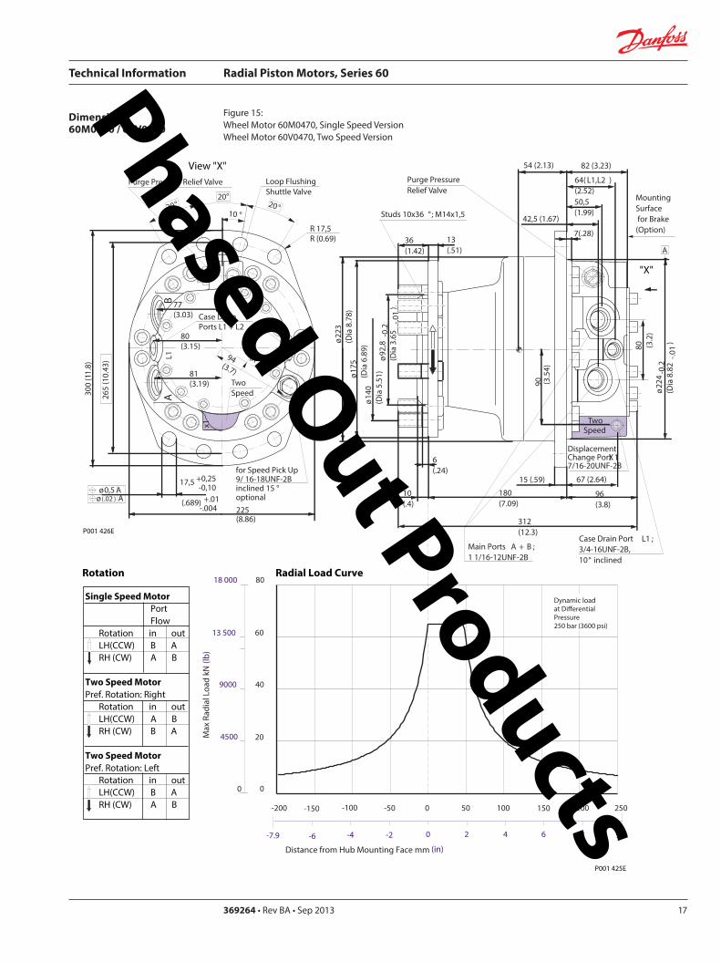
Technical Information Radial Piston Motors Series 60
369264 bull Rev BA bull Sep 2013 17
Dimensions60M0470 60V0470
Figure 15 Wheel Motor 60M0470 Single Speed VersionWheel Motor 60V0470 Two Speed Version
View X
TwoSpeed
L1A
B
300
(11
8)
81(319)
2020
2010
R 175R (069)
Purge Pressure Relief Valve
Case Drain Ports L1 + L2
degdeg
degdeg
Loop Flushing Shuttle Valve
L2
x1
265
(10
43)
175 +025-010
(689) +01 -004
30deg
for Speed Pick Up9 16-18UNF-2Binclined 15 degoptional
oslash05 Aoslash(02 ) A
80(315)
77(303)
94(37)
225(886)
P001 426E
oslash92
8-0
2(D
ia 3
65
-01
)
DisplacementChange Port X1716-20UNF-2B
Main Ports A + B 1 116-12UNF-2B
Studs 10x36 deg M14x15
13(51)
36(142)
6(24)
oslash14
0(D
ia 5
51)
oslash17
5(D
ia 6
89)
oslash22
3(D
ia 8
78)
Case Drain Port L1 34-16UNF-2B10deg inclined
64( L1L2 )(252)
54 (213)
7(28)
425 (167)
MountingSurface for Brake (Option)
Purge Pressure Relief Valve
312(123)
15 (59)
180(709)
oslash22
4-0
2(D
ia 8
82
-01
)
80 (32
)
67 (264)
90 (35
4)
82 (323)
505(199)
96(38)
TwoSpeed
A
10(4)
X
Single Speed MotorPortFlow
Rotation in outLH(CCW) B ARH (CW) A B
Two Speed MotorPref Rotation Right
Rotation in outLH(CCW) A BRH (CW) B A
Two Speed MotorPref Rotation Left
Rotation in outLH(CCW) B ARH (CW) A B
Rotation Radial Load Curve
P001 425E
Distance from Hub Mounting Face mm (in)
-4 -2 0 2 6-6-79 4 8 99
-200 -100 -50 0 50 100 150 200-150 250
Max
Rad
ial L
oad
kN (
lb)
0
20
40
60
4500
9000
0
13 500
18 000 80
Dynamic loadat DierentialPressure250 bar (3600 psi)
Phased Out Products
Technical Information Radial Piston Motors Series 60
5369264 bull Rev BA bull Sep 201318
Dimensions60M0470 60V0470
Figure 16 Flange Motor 60M0470 Single Speed VersionFlange Motor 60V0470 Two Speed Version
Single Speed MotorPortFlow
Rotation in outLH(CCW) B ARH (CW) A B
Two Speed MotorPref Rotation Right
Rotation in outLH(CCW) A BRH (CW) B A
Two Speed MotorPref Rotation Left
Rotation in outLH(CCW) B ARH (CW) A B
View X
X
P001 427E
TwoSpeed
L1A
B
300
(11
8)
81(319)
2020
2010
R 175R (069)
Purge Pressure Relief Valve
Case Drain Ports L1 + L2
degdeg
degdeg
Loop Flushing Shuttle Valve
L2
x1
265
(10
43)
175 +025-010
(689) +01 -004
30deg
for Speed Pick Up9 16-18UNF-2Binclined 15 degoptional
oslash05 Aoslash(02 ) A
80(315)
77(303)
94(37)
225(886)
P001 426E
Rotation Radial Load Curve
Dynamic loadat DierentialPressure250 bar (3600 psi)
Distance from Hub Mounting Face mm (in)
-4 -2 0 2 6-6-79 4 8 99
-200 -100 -50 0 50 100 150 200-150 250
Max
Rad
ial L
oad
kN (
lb)
0
20
40
60
4500
9000
13 500
0
oslash92
8-0
2(D
ia 3
65
-01
)
DisplacementChange Port X1716-20UNF-2B
Main Ports A + B 1 116-12UNF-2B25deg inclined
Studs 5x72 deg M14x15
12(47)
37(146)
6(24)
oslash14
0(D
ia 5
51)
oslash17
5(D
ia 6
89)
oslash22
3(D
ia 8
78)
Case Drain Ports L1 34-16UNF-2B10deg inclined
64( L1L2 )(252)
25 (98)
7(28)
425 (167)
MountingSurface for Brake (Option)
Purge Pressure Relief Valve
280(110)
15 (59)147(579)
oslash22
4-0
2(D
ia 8
82
-01
)
80 (32
)
67 (264)90 (3
54)
82 (323)
505(199)
96(38)
Two Speed
A
10(4)
Phased Out Products
Technical Information Radial Piston Motors Series 60
369264 bull Rev BA bull Sep 2013 19
Dimensions60M0470 60V0470
Figure 17 Shaft Motor 60M0470 Single Speed VersionShaft Motor 60V0470 Two Speed Version
Single Speed MotorPortFlow
Rotation in outLH(CCW) B ARH (CW) A B
Two Speed MotorPref Rotation Right
Rotation in outLH(CCW) A BRH (CW) B A
Two Speed MotorPref Rotation Left
Rotation in outLH(CCW) B ARH (CW) A B
View X
P001 428E
TwoSpeed
L1A
B
300
(11
8)
81(319)
2020
2010
R 175R (069)
Purge Pressure Relief Valve
Case Drain Ports L1 + L2
degdeg
degdeg
Loop Flushing Shuttle Valve
L2
x1
265
(10
43)
175 +025-010
(689) +01 -004
30deg
for Speed Pick Up9 16-18UNF-2Binclined 15 degoptional
oslash05 Aoslash(02 ) A
80(315)
77(303)
94(37)
225(886)
X
P001 426E
Rotation
Max Radial Load
DisplacementChange Port X1716-20UNF-2B
Main Ports A + B 1 116-12UNF-2B25deg inclined
Case Drain Port L1 34-16UNF-2B10deg inclined
395 (156)
18 ( L1L2 )(7)
MountingSurface for Brake (Option)
Purge Pressure Relief Valve
oslash22
3(D
ia 8
78)
80 (32
)
15 (59)
90 (35
4)
315 (124)
Two Speed
23(91)10 (39)
oslash20
0-0
07
(Dia
787
4-0
03)
312(123)
203 (799)
39(154)
54 (213)
38-
16U
NC
x15
(59)
full
THD
254
(10
)
34(134)
R25 +02(R10 +01 )
87 (343)
47(185)
Shaft Spline Data5 ssalC a1129B ISNA Spline standard
Spline Fit Pitch D
03 elgnA erusserPNo of teethSplineMajor Dia
A
-50 -40 -30 -20 -10 0
-2 -1
50
60
30
40
20
0
10
Allo
wab
lera
dial
Loa
d kN
(lb
)
Distance from Shaftshoulder mm (in)
0
2250
6750
9000
11250
4500
13500
0
Dynamic loadat ∆p = 250 bar (3600 psi)
Flat Root Side Fit4863 (1916)
231224508 (20)
Phased Out Products
Technical Information Radial Piston Motors Series 60
5369264 bull Rev BA bull Sep 201320
Dimensions60M0780 60V780
Figure 18 Wheel Motor 60M0780 Single Speed VersionWheel Motor 60V0780 TwoSpeed Version
Single Speed MotorPortFlow
Rotation in outLH(CCW) B ARH (CW) A B
Two Speed MotorPref Rotation Right
Rotation in outLH(CCW) A BRH (CW) B A
Two Speed MotorPref Rotation Left
Rotation in outLH(CCW) B ARH (CW) A B
20
40
60
80
0
4500
9000
13 500
18 000
Max
Rad
ial L
oad
kN (
lb)
Dynamic load atDierential Pressure250 bar (3600 psi)
Distance from Hub Mounting Face mm (in)
-200 -150 -100 -50 0 50 100 150 200 250
-79 -6 -4 -2 0 2 4 6 8 98
oslash16
08
-02
(Dia
63
3 -0
1)
DisplacementChange Port X1716-20UNF-2B
Main Ports A + B 1 116-12UNF-2B25deg inclined
Studs 6x60 deg M18x15
15(6)
36(142)
8(31)
oslash20
5(D
ia 8
1)
oslash24
7(D
ia 9
7)
oslash26
6(D
ia 1
05)
Case Drain Port L134-16UNF-2B10deg inclined
70( L1L2 ) (276)
58 (228)
7(28)
44 (173)
MountingSurface for Brake (Option)
Purge Pressure Relief Valve
334(123)
17 (7)
195(768)
oslash25
3-0
2(D
ia 9
96
-01
)96 (38
)
72 (283)
106
(42
)
88 (35)
51(201)
104(409)
A
TwoSpeed
17(7)
View X
for Speed Pick Up9 16-18UNF-2Binclined 15 degoptional
L2L1A
B
335
(13
2)
267(1051)
R 175R (069)
Purge Pressure Relief Valve
Case Drain Ports L1 + L2
Loop Flushing Shuttle Valve
x1
TwoSpeed
300
(11
81)
175 +025-010
(689) +01 -004
oslash05 Aoslash(02 ) A
30deg
15deg15deg
15deg15deg
96(38)
93(37)
91(36)
109(43)
P001 435E
P001 436E
Rotation Radial Load Curve
X
Phased Out Products
Technical Information Radial Piston Motors Series 60
369264 bull Rev BA bull Sep 2013 21
Dimensions60M0780 60 V780
Figure 19 Flange Motor 60M0780 Single Speed VersionFlange Motor 60V0780 Two Speed Version
Single Speed MotorPortFlow
Rotation in outLH(CCW) B ARH (CW) A B
Two Speed MotorPref Rotation Right
Rotation in outLH(CCW) A BRH (CW) B A
Two Speed MotorPref Rotation Left
Rotation in outLH(CCW) B ARH (CW) A B
View X
X
Max
Rad
ial L
oad
kN (
lb)
0
20
40
60
4500
9000
13 500
0
8018 000
Distance from Hub Mounting Face mm (in)
-4 -2 0 2 6-6-79 4 8 99
-200 -100 -50 0 50 100 150 200-150 250
Dynamic loadat DierentialPressure250 bar (3600 psi)
72 (283)
DisplacementChange Port X1716-20UNF-2B
Main Ports A + B 1 116-12UNF-2B25deg inclined
Case Drain Port L134-16UNF-2B
10deg inclined
70( L1L2 )(276)
27 (106)
7(28)
44 (173)
MountingSurface for Brake (Option)
304(119)
17 (7)
25(10)
oslash25
3-0
2(D
ia 9
96
-01
)
96 (38
)
106
(42
)
88 (35)
51(201)
104(409)
Two Speed
A
oslash16
08
-02
(Dia
63
3 -0
1)
Studs 6x60 deg M18x15
15(6)
36(142)
7(3)
oslash20
5(D
ia 8
1)
oslash24
7(D
ia 9
7)
oslash26
6(D
ia 1
05)
Purge Pressure Relief Valve
164(65)
for Speed Pick Up9 16-18UNF-2Binclined 15 degoptional
L2L1A
B
335
(13
2)
267(1051)
R 175R (069)
Purge Pressure Relief Valve
Case Drain Ports L1 + L2
Loop Flushing Shuttle Valve
x1
TwoSpeed
300
(11
81)
175 +025-010
(689) +01 -004
oslash05 Aoslash(02 ) A
30deg
15deg15deg
15deg15deg
96(38)
93(37)
91(36)
109(43)
P001 436E
P001 437E
Rotation Radial Load Curve
Phased Out Products
Technical Information Radial Piston Motors Series 60
5369264 bull Rev BA bull Sep 201322
Dimensions60M0780 60V780
Figure 20 Shaft Motor 60M0780 Single Speed VersionShaft Motor 60V0780 Two Speed Version
Single Speed MotorPortFlow
Rotation in outLH(CCW) B ARH (CW) A B
Two Speed MotorPref Rotation Right
Rotation in outLH(CCW) A BRH (CW) B A
Two Speed MotorPref Rotation Left
Rotation in outLH(CCW) B ARH (CW) A B
View X
for Speed Pick Up9 16-18UNF-2Binclined 15 degoptional
L2L1A
B
335
(13
2)
267(1051)
R 175R (069)
Purge Pressure Relief Valve
Case Drain Ports L1 + L2
Loop Flushing Shuttle Valve
x1
TwoSpeed
300
(11
81)
175 +025-010
(689) +01 -004
oslash05 Aoslash(02 ) A
30deg
15deg15deg
15deg15deg
96(38)
93(37)
91(36)
109(43)
X
P001 436E
Rotation
Max Radial Load
DisplacementChange Port X1716-20UNF-2B
Main Ports A + B1 116-12UNF-2B25deg inclined
Case Drain Port L134-16UNF-2B10deg inclined
44 (173)
18 ( L1L2 ) (71)
MountingSurface for Brake (Option)
Purge Pressure Relief Valve
oslash26
7(D
ia 1
051
)96 (38
)
16 (63)
106
(42
)
37 (146)
Two Speed
25(98)16 (63)
oslash22
4-0
15
(Dia
88
19-0
06)
343(1350)
215 (846)
40(157)
70 (276)
38-
16 U
NC
x15
(59)
full
THD
381
(15
)
46(181)
R3 +02(R12 +01 )
97 (382)
54(213)
A
-100 -80 -60 -40 -20 0
-4 -2
100
60
80
40
0
20
Allo
wab
lera
dial
Loa
d kN
(lb)
Distance from Shaftshoulder mm (in)
0
9000
13500
4500
18000
0
22500
P001 438E
Dynamic load at∆p = 250 bar (3600 psi)
Shaft Spline Data5 ssalC a1129B ISNA Spline standard
Spline Fit Pitch D
03 elgnA erusserPNo of teethSplineMajor Dia
Flat Root Side Fit635 (25)
208166667 (2625)
Phased Out Products
Technical Information Radial Piston Motors Series 60
369264 bull Rev BA bull Sep 2013 23
Dimensions60M1048 60V1048
Figure 21 Wheel Motor 60M1048 Single Speed VersionWheel Motor 60V0470 Two Speed Version
Single Speed MotorPortFlow
Rotation in outLH(CCW) B ARH (CW) A B
Two Speed MotorPref Rotation Right
Rotation in outLH(CCW) A BRH (CW) B A
Two Speed MotorPref Rotation Left
Rotation in outLH(CCW) B ARH (CW) A B
View X
P001 414E
X
P001 415E
295(1161)
x110
degdeg
L1A
B
R 20 R (079)
108(425)
108(425)
Purge Pressure Relief Valve Loop Flushing Shuttle Valve
L2
TwoSpeed37
5 (1
476
)
2020
20
Case Drain Ports L1 + L2
degdeg
335
(13
19)
225 +025-010
(89) +01 -004
30deg
for Speed Pick Up9 16-18UNF-2Binclined 15 degoptional
oslash075oslash(03 )
AA
118(465)
Rotation Radial Load Curve
20
40
60
80
100
0
4500
9000
13 500
18 000
22 500
Max
Rad
ial L
oad
kN (
lb)
Distance from Hub Mounting Face mm (in)
-200 -150 -100 -50 0 50 100 150 200 250
-79 -6 -4 -2 0 2 4 6 8 98
Dynamic load atDierentialPressure250 bar (3600 psi)
Studs 5x72 deg M22x15
Case Drain Ports L1 + L2 34-16UNF-2B
66( L2 ) (260)
565(222)
Main Ports A + B 075-Code 62Split Flange Boss per SAE J 51838-16UNC-2B 22 (088) min full thread depth
8 (31)
48 (189)
MountingSurface for Brake (Option)
16(63)
47(185)
Purge Pressure Relief Valve
112(441)
379(1492)
19 (75)
220(866)
8 (31)
oslash17
58
-02
(Dia
69
2 -0
1)
oslash22
5(D
ia 8
86)
280
(Dia
11
02)oslash
292
(Dia
115
0)
508
(20
0)
285
-02
(11
22-0
1)
96 (37
8)
DisplacementChange Port X1716-20UNF-2B
79 (31)
115
(45
3)
Two Speed
96 (378)
238(94)
81( L1 )(319)
24(9)
A
Phased Out Products
Technical Information Radial Piston Motors Series 60
5369264 bull Rev BA bull Sep 201324
Dimensions60M1048 60V1048
Figure 22 Flange Motor 60M1048 Single Speed VersionFlange Motor 60V1048 Two Speed Version
Single Speed MotorPortFlow
Rotation in outLH(CCW) B ARH (CW) A B
Two Speed MotorPref Rotation Right
Rotation in outLH(CCW) A BRH (CW) B A
Two Speed MotorPref Rotation Left
Rotation in outLH(CCW) B ARH (CW) A B
View X
X
295(1161)
x1
10deg
deg
L1A
B
R 20 R (079)
108(425)
108(425)
Purge Pressure Relief Valve Loop Flushing Shuttle Valve
L2
TwoSpeed37
5 (1
476
)
2020
20
Case Drain Ports L1 + L2
degdeg
335
(13
19)
225 +025-010
(89) +01 -004
30deg
for Speed Pick Up9 16-18UNF-2Binclined 15 degoptional
oslash075oslash(03 )
AA
118(465)
Dynamic loadat DierentialPressure250 bar (3600 psi)
Max
Rad
ial L
oad
kN (
lb)
0
20
40
60
4500
9000
13 500
0
Distance from Hub Mounting Face mm (in)
-4 -2 0 2 6-6-79 4 8 99
-200 -100 -50 0 50 100 150 200-150 250
Studs 6x60 deg M18x15
Case Drain Ports L1 + L2 34-16UNF-2B
66( L2 ) (26)
255(100)
Main Ports A + B 075-Code 62Split Flange Boss per SAE J 51838-16UNC-2B 22 (088) min full thread depth
8(31)
48 (189)
MountingSurface for Brake (Option)
15(59)
36(142)
Purge Pressure Relief Valve
112(441)
322(127)
19 (75)
1745(687)
6(24)
oslash16
08
-02
(Dia
63
3 -0
1)
oslash20
5 (D
ia 8
07)
250
(Dia
98
4)
oslash29
2(D
ia11
50)
508
(20
)
285
-02
(11
22-0
1)
96 (37
8)
DisplacementChange Port X1716-20UNF-2B
79 (311)11
5 (4
53)
Two Speed
96 (378)
238(94)
81( L1 )(319)
A
255 (10)
P001 415E
Rotation Radial Load Curve
P001 416E
Phased Out Products
Technical Information Radial Piston Motors Series 60
369264 bull Rev BA bull Sep 2013 25
Dimensions60M1048 60V1048
Figure 23 Shaft Motor 60M1048 Single Speed VersionShaft Motor 60M1048 Two Speed Version
Single Speed MotorPortFlow
Rotation in outLH(CCW) B ARH (CW) A B
Two Speed MotorPref Rotation Right
Rotation in outLH(CCW) A BRH (CW) B A
Two Speed MotorPref Rotation Left
Rotation in outLH(CCW) B ARH (CW) A B
View X
295(1161)
x110
degdeg
L1A
B
R 20 R (079)
108(425)
108(425)
Purge Pressure Relief Valve Loop Flushing Shuttle Valve
L2
TwoSpeed37
5 (1
476
)
2020
20
Case Drain Ports L1 + L2
degdeg
335
(13
19)
225 +025-010
(89) +01 -004
30deg
for Speed Pick Up9 16-18UNF-2Binclined 15 degoptional
oslash075oslash(03 )
AA
118(465)
P001 415E
Rotation
Max Radial Load
X
73 ( L1 )(287)
28(110)13 (51)
oslash28
0-0
15
(Dia
110
24-0
06)
372(146)
2325 (915)
50 (197)
70 (276)
38-
16U
NC
15 (
59) f
ull T
HD
381
(15
)
46(181)
123 (484)
R 3 +02(R12 +01 )
515 (203)
Main Ports A + B 075-Code 62Split Flange Boss per SAE J 51838-16UNC-2B22 (088) min full thread depth
Case Drain Ports L1+L234-16UNF-2B
40 (157)
MountingSurface for Brake (Option)
104(41)
238(94)
508
(20
0)
oslash29
2(D
ia11
5)96 (37
8)
DisplacementChange Port X1716-20UNF-2B
17(67)
115
(45
3)
Two Speed
58( L2 )(228)
PurgePressureRelief ValveA
-100 -80 -60 -40 -20 0
-4 -2
120
60
80
40
0
20
Allo
wab
lera
dial
Loa
d kN
(lb)
Distance from Shaftshoulder mm (in)
0
9000
13500
4500
18000
0
22500 10027000
P001 417E
Dynamic load at ∆p = 250 bar (3600 psi)
Shaft Spline Data5 ssalC a1129B ISNA Spline standard
Spline Fit Pitch Dia
03 elgnA erusserPNo of teethSplineMajor Dia
Flat Root Side Fit73025 (30)
23816762 (30)
Phased Out Products
Technical Information Radial Piston Motors Series 60
5369264 bull Rev BA bull Sep 201326
Dimensions60M1750 60V1750
Figure 24 Wheel Motor 60M1750 Single Speed VersionWheel Motor 60V1750 Two Speed Version
Single Speed MotorPortFlow
Rotation in outLH(CCW) B ARH (CW) A B
Two Speed MotorPref Rotation Right
Rotation in outLH(CCW) A BRH (CW) B A
Two Speed MotorPref Rotation Left
Rotation in outLH(CCW) B ARH (CW) A B
View X
X
Rotation Radial Load Curve
P001 430E
P001 429E
L2L1A
B
425
(16
73)
Purge Pressure Relief Valve
Case Drain Ports L1 + L2
Loop Flushing Shuttle Valve
x1
Two Speed
385
(15
16)
225 +025-010
(89) +01 -004
oslash075 Aoslash(03 ) A
30deg
for Speed Pick Up9 16-18UNF-2Binclined 15 degoptional
15deg15deg
15deg15deg
350(1378)
R 20 R (079)
124(488)
124(488)
138(543)
Dynamic load atDierentialPressure250 bar (3600 psi)
(in)Distance from Hub Mounting Face mm
-200 -150 -100 -50 0 50 100 150 200 250
-79 -6 -4 -2 0 2 4 6 8 98
Max
Rad
ial L
oad
kN (
lb)
20
40
140
160
60
80
100
120
180
0
4500
9000
13 500
27 000
36 000
18 000
22 500
31 500
40 500
0
Studs 10x36 deg M22x15
Case Drain Ports L1 + L2 78-14UNF-2B
69(272)
Main Ports A + B 100-Code 62Split Flange Boss per SAE J 518716-14UNC-2B 27 (106) min full thread depth
11(43)
66 (2598)
MountingSurface for Brake (Option)
16(63)
47(185)
Purge Pressure Relief Valve
132(520)
433(1705)
225 (886)
254(100)
8 (31)
oslash17
58
-02
(Dia
69
2 -0
1)
oslash22
5(D
ia 8
86)
280
(Dia
11
02)oslash
350
(Dia
137
8)
571
5(2
25)
oslash33
0-0
2(D
ia12
992
-008
)
115
(45
28)
DisplacementChange Port X1716-20UNF-2B
99 (390)
141
(55
5)
Two Speed
116 (4567)
2776(1093)
96( L1L2 )(378)
20(0787)
A
Phased Out Products
Technical Information Radial Piston Motors Series 60
369264 bull Rev BA bull Sep 2013 27
Dimensions60M1750 60V1750
Figure 25 Flange Motor 60M1750 Single Speed VersionFlange Motor 60V1750 Two Speed Version
Single Speed MotorPortFlow
Rotation in outLH(CCW) B ARH (CW) A B
Two Speed MotorPref Rotation Right
Rotation in outLH(CCW) A BRH (CW) B A
Two Speed MotorPref Rotation Left
Rotation in outLH(CCW) B ARH (CW) A B
View X
X
P001 430E
Rotation Radial Load Curve
P001 431E
L2L1A
B
425
(16
73)
Purge Pressure Relief Valve
Case Drain Ports L1 + L2
Loop Flushing Shuttle Valve
x1
Two Speed
385
(15
16)
225 +025-010
(89) +01 -004
oslash075 Aoslash(03 ) A
30deg
for Speed Pick Up9 16-18UNF-2Binclined 15 degoptional
15deg15deg
15deg15deg
350(1378)
R 20 R (079)
124(488)
124(488)
138(543)
0
Dynamic loadat DierentialPressure250 bar (3600 psi)
Distance from Hub Mounting Face mm (in)
-6 -4 -2 0 2 64 8 99-79
-200 -100 -50 0 50 100 150 200-150 250
Max
Rad
ial L
oad
kN (
lb)
0
20
40
60
4500
9000
13 500
8018 000
10022 500
12027 000
14031 500
16036 000
18040 500
Studs 10x36 deg M22x15
Case Drain Ports L1 + L2 78-14UNF-2B
32(126)
Main Ports A + B 100-Code 62Split Flange Boss per SAE J 518716-14UNC-2B 27 (106) min full thread depth
11(43)
66 (2598)
MountingSurface for Brake (Option)
16(63)
47(185)
Purge Pressure Relief Valve
132(520)
389(1531)
225 (886)
210(1827)
8 (31)
oslash17
58
-02
(Dia
69
2 -0
1)
oslash22
5(D
ia 8
86)
280
(Dia
11
02)oslash
350
(Dia
137
8)
571
5(2
25)
oslash33
0-0
2(D
ia 1
299
2-0
08)
115
(45
28)
DisplacementChange Port X1716-20UNF-2B
99 (390)
141
(55
5)
Two Speed
116 (4567)
2776(1093)
96( L1 L2 )(378)
29 (114)
A
Phased Out Products
Technical Information Radial Piston Motors Series 60
5369264 bull Rev BA bull Sep 201328
Dimensions60M1750 60V1750
Figure 26 Shaft Motor 60M1750 Single Speed VersionShaft Motor 60V1750 Two Speed Version
Single Speed MotorPortFlow
Rotation in outLH(CCW) B ARH (CW) A B
Two Speed MotorPref Rotation Right
Rotation in outLH(CCW) A BRH (CW) B A
Two Speed MotorPref Rotation Left
Rotation in outLH(CCW) B ARH (CW) A B
View X
L2L1A
B
425
(16
73)
Purge Pressure Relief Valve
Case Drain Ports L1 + L2
Loop Flushing Shuttle Valve
x1
Two Speed
385
(15
16)
225 +025-010
(89) +01 -004
oslash075 Aoslash(03 ) A
30deg
for Speed Pick Up9 16-18UNF-2Binclined 15 degoptional
15deg15deg
15deg15deg
350(1378)
R 20 R (079)
124(488)
124(488)
138(543)
P001 430E
Rotation
X
Max Radial Load
Displacementchange Port X1716-20UNF-2B
24(94)15 (59)
oslash31
5-0
15
(Dia
124
02-0
06)
440(173)
2835 (1116)
48 (189)
90 (354)
12-
13 U
NC
X22
(86)
full
THD
381
(15
)
63(248)
141 (555)
R4 +02(R16 +01 )
97 (382)
Main Ports A + B 100-Code 62Split Flange Boss per SAE J 518716-14UNC-2B27 (106) min full thread depth
Case Drain Ports L1+L278-20UNF-2B
20 (079) ( L1+L2 )
50 (197)
MountingSurface for Brake (Option)Purge Pressure
Relief Valve
121 (48)
278(109)
572
(22
5)
oslash33
0(D
ia12
99)11
5 (4
53)
17 (67)
141
(55
5)
Two Speed
9 (35)
oslash35
0(D
ia13
78)
A
-100 -80 -60 -40 -20 0
-4 -2
200
100
150
0
50
Allo
wab
lera
dial
Loa
d kN
(lb)
Distance from Shaftshoulder mm (in)
0
22500
11250
33750
0
45000
P001 432E
Dynamic load at ∆p = 250 bar (3600 psi)
Shaft Spline Data5 ssalC a1129B ISNA Spline standard
Spline Fit Pitch Dia
03 elgnA erusserPNo of teethSplineMajor Dia
Flat Root Side Fit889 (35)
288169207 (3625)
Phased Out Products
Technical Information Radial Piston Motors Series 60
369264 bull Rev BA bull Sep 2013 29
NotesPhased Out Products
Technical Information Radial Piston Motors Series 60
5369264 bull Rev BA bull Sep 201330
DimensionsBrakes
Figure 27 Radial Piston Motor with Brake (0ptional)
P001 418E
Table 6 Brake Dimensions
Series Dimension
A B C
60M0470 23 (090) 74 (290) oslash212 (Dia 835)
60M0780 42 (165) 100 (394) oslash245 (Dia 965)
60M1048 30 (118) 90 (354) oslash280 (Dia 1102)
60M1750 38 (147) 107 (421) oslash320 (Dia 1260)
B
CX7
MountingFace
Mechanical BrakeRelease 1 to be used with Mech Brake Release 2
Mechanical BrakeRelease 2to be used with Mech Brake Release 1
A
Hydraulic BrakeRelease X7916-18UNF-2B
Mechanical BrakeRelease 1 to be used with Mech Brake Release 2
Mechanical BrakeRelease 2to be used with Mech Brake Release 1
TwoSpeed
X
View X
Phased Out Products
Technical Information Radial Piston Motors Series 60
369264 bull Rev BA bull Sep 2013 31
DimensionsSpeed Sensor
Figure 28 Radial Piston Motor with Speed Sensor (0ptional)
Section A - A (11)Speed Sensor
Connecto IdNoStraightRight angle
Connector is not supplied with the motorPlease order separatly using above Id No
Table 7 Speed Sensor Connector
Electrical details see page12
P001 444E
A
A
30deg 15 deg
31m
ax (1
22)
Pin 1Pin 2
Pin 3
Pin 4
Key Way
Wrench-Flats
Connector Insert
View Y
Y
127
(50)
500724500725
Phased Out Products
Comatrolwwwcomatrolcom
Schwarzmuumlller-Inverterwwwschwarzmueller-invertercom
Turolla wwwturollaocgcom
Valmovawwwvalmovacom
Hydro-Gear wwwhydro-gearcom
Daikin-Sauer-Danfosswwwdaikin-sauer-danfosscom
Danfoss Power Solutions is a global manufacturer and supplier of high-quality hydraulic and electronic components We specialize in providing state-of-the-art technology and solutions that excel in the harsh operating conditions of the mobile off -highway market Building on our extensive applications expertise we work closely with our customers to ensure exceptional performance for a broad range of off -highway vehicles
We help OEMs around the world speed up system development reduce costs and bring vehicles to market faster Danfoss ndash Your Strongest Partner in Mobile Hydraulics
Go to wwwpowersolutionsdanfosscom for further product information
Wherever off -highway vehicles are at work so is Danfoss
We off er expert worldwide support for our customers ensuring the best possible solutions for outstanding performance And with an extensive network of Global Service Partners we also provide comprehensive global service for all of our components
Please contact the Danfoss Power Solution representative nearest you
Products we off er
Bent Axis Motors
Closed Circuit Axial Piston Pumps and Motors
Displays
Electrohydraulic Power Steering
Electrohydraulics
Hydraulic Power Steering
Integrated Systems
Joysticks and Control Handles
Microcontrollers and Software
Open Circuit Axial Piston Pumps
Orbital Motors
PLUS+1reg GUIDE
Proportional Valves
Sensors
Steering
Transit Mixer Drives
Local address
Danfoss can accept no responsibility for possible errors in catalogues brochures and other printed material Danfoss reserves the right to alter its products without notice This also applies to products already on order provided that such alterations can be made without subsequential changes being necessary in specifications already agreedAll trademarks in this material are property of the respective companies Danfoss and the Danfoss logotype are trademarks of Danfoss AS All rights reserved
Danfoss Power Solutions22F Block C Yishan RdShanghai 200233 ChinaPhone +86 21 3418 5200
Danfoss Power Solutions GmbH amp Co OHGKrokamp 35D-24539 Neumuumlnster GermanyPhone +49 4321 871 0
Danfoss Power Solutions ApSNordborgvej 81DK-6430 Nordborg DenmarkPhone +45 7488 2222
Danfoss Power Solutions US Company2800 East 13th StreetAmes IA 50010 USAPhone +1 515 239 6000
369264 bull Rev BA bull Sep 2013 wwwdanfosscom copy Danfoss AS 2013-09
Phased Out Products
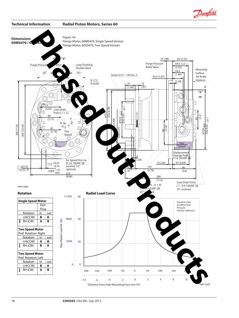
Technical Information Radial Piston Motors Series 60
5369264 bull Rev BA bull Sep 201318
Dimensions60M0470 60V0470
Figure 16 Flange Motor 60M0470 Single Speed VersionFlange Motor 60V0470 Two Speed Version
Single Speed MotorPortFlow
Rotation in outLH(CCW) B ARH (CW) A B
Two Speed MotorPref Rotation Right
Rotation in outLH(CCW) A BRH (CW) B A
Two Speed MotorPref Rotation Left
Rotation in outLH(CCW) B ARH (CW) A B
View X
X
P001 427E
TwoSpeed
L1A
B
300
(11
8)
81(319)
2020
2010
R 175R (069)
Purge Pressure Relief Valve
Case Drain Ports L1 + L2
degdeg
degdeg
Loop Flushing Shuttle Valve
L2
x1
265
(10
43)
175 +025-010
(689) +01 -004
30deg
for Speed Pick Up9 16-18UNF-2Binclined 15 degoptional
oslash05 Aoslash(02 ) A
80(315)
77(303)
94(37)
225(886)
P001 426E
Rotation Radial Load Curve
Dynamic loadat DierentialPressure250 bar (3600 psi)
Distance from Hub Mounting Face mm (in)
-4 -2 0 2 6-6-79 4 8 99
-200 -100 -50 0 50 100 150 200-150 250
Max
Rad
ial L
oad
kN (
lb)
0
20
40
60
4500
9000
13 500
0
oslash92
8-0
2(D
ia 3
65
-01
)
DisplacementChange Port X1716-20UNF-2B
Main Ports A + B 1 116-12UNF-2B25deg inclined
Studs 5x72 deg M14x15
12(47)
37(146)
6(24)
oslash14
0(D
ia 5
51)
oslash17
5(D
ia 6
89)
oslash22
3(D
ia 8
78)
Case Drain Ports L1 34-16UNF-2B10deg inclined
64( L1L2 )(252)
25 (98)
7(28)
425 (167)
MountingSurface for Brake (Option)
Purge Pressure Relief Valve
280(110)
15 (59)147(579)
oslash22
4-0
2(D
ia 8
82
-01
)
80 (32
)
67 (264)90 (3
54)
82 (323)
505(199)
96(38)
Two Speed
A
10(4)
Phased Out Products
Technical Information Radial Piston Motors Series 60
369264 bull Rev BA bull Sep 2013 19
Dimensions60M0470 60V0470
Figure 17 Shaft Motor 60M0470 Single Speed VersionShaft Motor 60V0470 Two Speed Version
Single Speed MotorPortFlow
Rotation in outLH(CCW) B ARH (CW) A B
Two Speed MotorPref Rotation Right
Rotation in outLH(CCW) A BRH (CW) B A
Two Speed MotorPref Rotation Left
Rotation in outLH(CCW) B ARH (CW) A B
View X
P001 428E
TwoSpeed
L1A
B
300
(11
8)
81(319)
2020
2010
R 175R (069)
Purge Pressure Relief Valve
Case Drain Ports L1 + L2
degdeg
degdeg
Loop Flushing Shuttle Valve
L2
x1
265
(10
43)
175 +025-010
(689) +01 -004
30deg
for Speed Pick Up9 16-18UNF-2Binclined 15 degoptional
oslash05 Aoslash(02 ) A
80(315)
77(303)
94(37)
225(886)
X
P001 426E
Rotation
Max Radial Load
DisplacementChange Port X1716-20UNF-2B
Main Ports A + B 1 116-12UNF-2B25deg inclined
Case Drain Port L1 34-16UNF-2B10deg inclined
395 (156)
18 ( L1L2 )(7)
MountingSurface for Brake (Option)
Purge Pressure Relief Valve
oslash22
3(D
ia 8
78)
80 (32
)
15 (59)
90 (35
4)
315 (124)
Two Speed
23(91)10 (39)
oslash20
0-0
07
(Dia
787
4-0
03)
312(123)
203 (799)
39(154)
54 (213)
38-
16U
NC
x15
(59)
full
THD
254
(10
)
34(134)
R25 +02(R10 +01 )
87 (343)
47(185)
Shaft Spline Data5 ssalC a1129B ISNA Spline standard
Spline Fit Pitch D
03 elgnA erusserPNo of teethSplineMajor Dia
A
-50 -40 -30 -20 -10 0
-2 -1
50
60
30
40
20
0
10
Allo
wab
lera
dial
Loa
d kN
(lb
)
Distance from Shaftshoulder mm (in)
0
2250
6750
9000
11250
4500
13500
0
Dynamic loadat ∆p = 250 bar (3600 psi)
Flat Root Side Fit4863 (1916)
231224508 (20)
Phased Out Products
Technical Information Radial Piston Motors Series 60
5369264 bull Rev BA bull Sep 201320
Dimensions60M0780 60V780
Figure 18 Wheel Motor 60M0780 Single Speed VersionWheel Motor 60V0780 TwoSpeed Version
Single Speed MotorPortFlow
Rotation in outLH(CCW) B ARH (CW) A B
Two Speed MotorPref Rotation Right
Rotation in outLH(CCW) A BRH (CW) B A
Two Speed MotorPref Rotation Left
Rotation in outLH(CCW) B ARH (CW) A B
20
40
60
80
0
4500
9000
13 500
18 000
Max
Rad
ial L
oad
kN (
lb)
Dynamic load atDierential Pressure250 bar (3600 psi)
Distance from Hub Mounting Face mm (in)
-200 -150 -100 -50 0 50 100 150 200 250
-79 -6 -4 -2 0 2 4 6 8 98
oslash16
08
-02
(Dia
63
3 -0
1)
DisplacementChange Port X1716-20UNF-2B
Main Ports A + B 1 116-12UNF-2B25deg inclined
Studs 6x60 deg M18x15
15(6)
36(142)
8(31)
oslash20
5(D
ia 8
1)
oslash24
7(D
ia 9
7)
oslash26
6(D
ia 1
05)
Case Drain Port L134-16UNF-2B10deg inclined
70( L1L2 ) (276)
58 (228)
7(28)
44 (173)
MountingSurface for Brake (Option)
Purge Pressure Relief Valve
334(123)
17 (7)
195(768)
oslash25
3-0
2(D
ia 9
96
-01
)96 (38
)
72 (283)
106
(42
)
88 (35)
51(201)
104(409)
A
TwoSpeed
17(7)
View X
for Speed Pick Up9 16-18UNF-2Binclined 15 degoptional
L2L1A
B
335
(13
2)
267(1051)
R 175R (069)
Purge Pressure Relief Valve
Case Drain Ports L1 + L2
Loop Flushing Shuttle Valve
x1
TwoSpeed
300
(11
81)
175 +025-010
(689) +01 -004
oslash05 Aoslash(02 ) A
30deg
15deg15deg
15deg15deg
96(38)
93(37)
91(36)
109(43)
P001 435E
P001 436E
Rotation Radial Load Curve
X
Phased Out Products
Technical Information Radial Piston Motors Series 60
369264 bull Rev BA bull Sep 2013 21
Dimensions60M0780 60 V780
Figure 19 Flange Motor 60M0780 Single Speed VersionFlange Motor 60V0780 Two Speed Version
Single Speed MotorPortFlow
Rotation in outLH(CCW) B ARH (CW) A B
Two Speed MotorPref Rotation Right
Rotation in outLH(CCW) A BRH (CW) B A
Two Speed MotorPref Rotation Left
Rotation in outLH(CCW) B ARH (CW) A B
View X
X
Max
Rad
ial L
oad
kN (
lb)
0
20
40
60
4500
9000
13 500
0
8018 000
Distance from Hub Mounting Face mm (in)
-4 -2 0 2 6-6-79 4 8 99
-200 -100 -50 0 50 100 150 200-150 250
Dynamic loadat DierentialPressure250 bar (3600 psi)
72 (283)
DisplacementChange Port X1716-20UNF-2B
Main Ports A + B 1 116-12UNF-2B25deg inclined
Case Drain Port L134-16UNF-2B
10deg inclined
70( L1L2 )(276)
27 (106)
7(28)
44 (173)
MountingSurface for Brake (Option)
304(119)
17 (7)
25(10)
oslash25
3-0
2(D
ia 9
96
-01
)
96 (38
)
106
(42
)
88 (35)
51(201)
104(409)
Two Speed
A
oslash16
08
-02
(Dia
63
3 -0
1)
Studs 6x60 deg M18x15
15(6)
36(142)
7(3)
oslash20
5(D
ia 8
1)
oslash24
7(D
ia 9
7)
oslash26
6(D
ia 1
05)
Purge Pressure Relief Valve
164(65)
for Speed Pick Up9 16-18UNF-2Binclined 15 degoptional
L2L1A
B
335
(13
2)
267(1051)
R 175R (069)
Purge Pressure Relief Valve
Case Drain Ports L1 + L2
Loop Flushing Shuttle Valve
x1
TwoSpeed
300
(11
81)
175 +025-010
(689) +01 -004
oslash05 Aoslash(02 ) A
30deg
15deg15deg
15deg15deg
96(38)
93(37)
91(36)
109(43)
P001 436E
P001 437E
Rotation Radial Load Curve
Phased Out Products
Technical Information Radial Piston Motors Series 60
5369264 bull Rev BA bull Sep 201322
Dimensions60M0780 60V780
Figure 20 Shaft Motor 60M0780 Single Speed VersionShaft Motor 60V0780 Two Speed Version
Single Speed MotorPortFlow
Rotation in outLH(CCW) B ARH (CW) A B
Two Speed MotorPref Rotation Right
Rotation in outLH(CCW) A BRH (CW) B A
Two Speed MotorPref Rotation Left
Rotation in outLH(CCW) B ARH (CW) A B
View X
for Speed Pick Up9 16-18UNF-2Binclined 15 degoptional
L2L1A
B
335
(13
2)
267(1051)
R 175R (069)
Purge Pressure Relief Valve
Case Drain Ports L1 + L2
Loop Flushing Shuttle Valve
x1
TwoSpeed
300
(11
81)
175 +025-010
(689) +01 -004
oslash05 Aoslash(02 ) A
30deg
15deg15deg
15deg15deg
96(38)
93(37)
91(36)
109(43)
X
P001 436E
Rotation
Max Radial Load
DisplacementChange Port X1716-20UNF-2B
Main Ports A + B1 116-12UNF-2B25deg inclined
Case Drain Port L134-16UNF-2B10deg inclined
44 (173)
18 ( L1L2 ) (71)
MountingSurface for Brake (Option)
Purge Pressure Relief Valve
oslash26
7(D
ia 1
051
)96 (38
)
16 (63)
106
(42
)
37 (146)
Two Speed
25(98)16 (63)
oslash22
4-0
15
(Dia
88
19-0
06)
343(1350)
215 (846)
40(157)
70 (276)
38-
16 U
NC
x15
(59)
full
THD
381
(15
)
46(181)
R3 +02(R12 +01 )
97 (382)
54(213)
A
-100 -80 -60 -40 -20 0
-4 -2
100
60
80
40
0
20
Allo
wab
lera
dial
Loa
d kN
(lb)
Distance from Shaftshoulder mm (in)
0
9000
13500
4500
18000
0
22500
P001 438E
Dynamic load at∆p = 250 bar (3600 psi)
Shaft Spline Data5 ssalC a1129B ISNA Spline standard
Spline Fit Pitch D
03 elgnA erusserPNo of teethSplineMajor Dia
Flat Root Side Fit635 (25)
208166667 (2625)
Phased Out Products
Technical Information Radial Piston Motors Series 60
369264 bull Rev BA bull Sep 2013 23
Dimensions60M1048 60V1048
Figure 21 Wheel Motor 60M1048 Single Speed VersionWheel Motor 60V0470 Two Speed Version
Single Speed MotorPortFlow
Rotation in outLH(CCW) B ARH (CW) A B
Two Speed MotorPref Rotation Right
Rotation in outLH(CCW) A BRH (CW) B A
Two Speed MotorPref Rotation Left
Rotation in outLH(CCW) B ARH (CW) A B
View X
P001 414E
X
P001 415E
295(1161)
x110
degdeg
L1A
B
R 20 R (079)
108(425)
108(425)
Purge Pressure Relief Valve Loop Flushing Shuttle Valve
L2
TwoSpeed37
5 (1
476
)
2020
20
Case Drain Ports L1 + L2
degdeg
335
(13
19)
225 +025-010
(89) +01 -004
30deg
for Speed Pick Up9 16-18UNF-2Binclined 15 degoptional
oslash075oslash(03 )
AA
118(465)
Rotation Radial Load Curve
20
40
60
80
100
0
4500
9000
13 500
18 000
22 500
Max
Rad
ial L
oad
kN (
lb)
Distance from Hub Mounting Face mm (in)
-200 -150 -100 -50 0 50 100 150 200 250
-79 -6 -4 -2 0 2 4 6 8 98
Dynamic load atDierentialPressure250 bar (3600 psi)
Studs 5x72 deg M22x15
Case Drain Ports L1 + L2 34-16UNF-2B
66( L2 ) (260)
565(222)
Main Ports A + B 075-Code 62Split Flange Boss per SAE J 51838-16UNC-2B 22 (088) min full thread depth
8 (31)
48 (189)
MountingSurface for Brake (Option)
16(63)
47(185)
Purge Pressure Relief Valve
112(441)
379(1492)
19 (75)
220(866)
8 (31)
oslash17
58
-02
(Dia
69
2 -0
1)
oslash22
5(D
ia 8
86)
280
(Dia
11
02)oslash
292
(Dia
115
0)
508
(20
0)
285
-02
(11
22-0
1)
96 (37
8)
DisplacementChange Port X1716-20UNF-2B
79 (31)
115
(45
3)
Two Speed
96 (378)
238(94)
81( L1 )(319)
24(9)
A
Phased Out Products
Technical Information Radial Piston Motors Series 60
5369264 bull Rev BA bull Sep 201324
Dimensions60M1048 60V1048
Figure 22 Flange Motor 60M1048 Single Speed VersionFlange Motor 60V1048 Two Speed Version
Single Speed MotorPortFlow
Rotation in outLH(CCW) B ARH (CW) A B
Two Speed MotorPref Rotation Right
Rotation in outLH(CCW) A BRH (CW) B A
Two Speed MotorPref Rotation Left
Rotation in outLH(CCW) B ARH (CW) A B
View X
X
295(1161)
x1
10deg
deg
L1A
B
R 20 R (079)
108(425)
108(425)
Purge Pressure Relief Valve Loop Flushing Shuttle Valve
L2
TwoSpeed37
5 (1
476
)
2020
20
Case Drain Ports L1 + L2
degdeg
335
(13
19)
225 +025-010
(89) +01 -004
30deg
for Speed Pick Up9 16-18UNF-2Binclined 15 degoptional
oslash075oslash(03 )
AA
118(465)
Dynamic loadat DierentialPressure250 bar (3600 psi)
Max
Rad
ial L
oad
kN (
lb)
0
20
40
60
4500
9000
13 500
0
Distance from Hub Mounting Face mm (in)
-4 -2 0 2 6-6-79 4 8 99
-200 -100 -50 0 50 100 150 200-150 250
Studs 6x60 deg M18x15
Case Drain Ports L1 + L2 34-16UNF-2B
66( L2 ) (26)
255(100)
Main Ports A + B 075-Code 62Split Flange Boss per SAE J 51838-16UNC-2B 22 (088) min full thread depth
8(31)
48 (189)
MountingSurface for Brake (Option)
15(59)
36(142)
Purge Pressure Relief Valve
112(441)
322(127)
19 (75)
1745(687)
6(24)
oslash16
08
-02
(Dia
63
3 -0
1)
oslash20
5 (D
ia 8
07)
250
(Dia
98
4)
oslash29
2(D
ia11
50)
508
(20
)
285
-02
(11
22-0
1)
96 (37
8)
DisplacementChange Port X1716-20UNF-2B
79 (311)11
5 (4
53)
Two Speed
96 (378)
238(94)
81( L1 )(319)
A
255 (10)
P001 415E
Rotation Radial Load Curve
P001 416E
Phased Out Products
Technical Information Radial Piston Motors Series 60
369264 bull Rev BA bull Sep 2013 25
Dimensions60M1048 60V1048
Figure 23 Shaft Motor 60M1048 Single Speed VersionShaft Motor 60M1048 Two Speed Version
Single Speed MotorPortFlow
Rotation in outLH(CCW) B ARH (CW) A B
Two Speed MotorPref Rotation Right
Rotation in outLH(CCW) A BRH (CW) B A
Two Speed MotorPref Rotation Left
Rotation in outLH(CCW) B ARH (CW) A B
View X
295(1161)
x110
degdeg
L1A
B
R 20 R (079)
108(425)
108(425)
Purge Pressure Relief Valve Loop Flushing Shuttle Valve
L2
TwoSpeed37
5 (1
476
)
2020
20
Case Drain Ports L1 + L2
degdeg
335
(13
19)
225 +025-010
(89) +01 -004
30deg
for Speed Pick Up9 16-18UNF-2Binclined 15 degoptional
oslash075oslash(03 )
AA
118(465)
P001 415E
Rotation
Max Radial Load
X
73 ( L1 )(287)
28(110)13 (51)
oslash28
0-0
15
(Dia
110
24-0
06)
372(146)
2325 (915)
50 (197)
70 (276)
38-
16U
NC
15 (
59) f
ull T
HD
381
(15
)
46(181)
123 (484)
R 3 +02(R12 +01 )
515 (203)
Main Ports A + B 075-Code 62Split Flange Boss per SAE J 51838-16UNC-2B22 (088) min full thread depth
Case Drain Ports L1+L234-16UNF-2B
40 (157)
MountingSurface for Brake (Option)
104(41)
238(94)
508
(20
0)
oslash29
2(D
ia11
5)96 (37
8)
DisplacementChange Port X1716-20UNF-2B
17(67)
115
(45
3)
Two Speed
58( L2 )(228)
PurgePressureRelief ValveA
-100 -80 -60 -40 -20 0
-4 -2
120
60
80
40
0
20
Allo
wab
lera
dial
Loa
d kN
(lb)
Distance from Shaftshoulder mm (in)
0
9000
13500
4500
18000
0
22500 10027000
P001 417E
Dynamic load at ∆p = 250 bar (3600 psi)
Shaft Spline Data5 ssalC a1129B ISNA Spline standard
Spline Fit Pitch Dia
03 elgnA erusserPNo of teethSplineMajor Dia
Flat Root Side Fit73025 (30)
23816762 (30)
Phased Out Products
Technical Information Radial Piston Motors Series 60
5369264 bull Rev BA bull Sep 201326
Dimensions60M1750 60V1750
Figure 24 Wheel Motor 60M1750 Single Speed VersionWheel Motor 60V1750 Two Speed Version
Single Speed MotorPortFlow
Rotation in outLH(CCW) B ARH (CW) A B
Two Speed MotorPref Rotation Right
Rotation in outLH(CCW) A BRH (CW) B A
Two Speed MotorPref Rotation Left
Rotation in outLH(CCW) B ARH (CW) A B
View X
X
Rotation Radial Load Curve
P001 430E
P001 429E
L2L1A
B
425
(16
73)
Purge Pressure Relief Valve
Case Drain Ports L1 + L2
Loop Flushing Shuttle Valve
x1
Two Speed
385
(15
16)
225 +025-010
(89) +01 -004
oslash075 Aoslash(03 ) A
30deg
for Speed Pick Up9 16-18UNF-2Binclined 15 degoptional
15deg15deg
15deg15deg
350(1378)
R 20 R (079)
124(488)
124(488)
138(543)
Dynamic load atDierentialPressure250 bar (3600 psi)
(in)Distance from Hub Mounting Face mm
-200 -150 -100 -50 0 50 100 150 200 250
-79 -6 -4 -2 0 2 4 6 8 98
Max
Rad
ial L
oad
kN (
lb)
20
40
140
160
60
80
100
120
180
0
4500
9000
13 500
27 000
36 000
18 000
22 500
31 500
40 500
0
Studs 10x36 deg M22x15
Case Drain Ports L1 + L2 78-14UNF-2B
69(272)
Main Ports A + B 100-Code 62Split Flange Boss per SAE J 518716-14UNC-2B 27 (106) min full thread depth
11(43)
66 (2598)
MountingSurface for Brake (Option)
16(63)
47(185)
Purge Pressure Relief Valve
132(520)
433(1705)
225 (886)
254(100)
8 (31)
oslash17
58
-02
(Dia
69
2 -0
1)
oslash22
5(D
ia 8
86)
280
(Dia
11
02)oslash
350
(Dia
137
8)
571
5(2
25)
oslash33
0-0
2(D
ia12
992
-008
)
115
(45
28)
DisplacementChange Port X1716-20UNF-2B
99 (390)
141
(55
5)
Two Speed
116 (4567)
2776(1093)
96( L1L2 )(378)
20(0787)
A
Phased Out Products
Technical Information Radial Piston Motors Series 60
369264 bull Rev BA bull Sep 2013 27
Dimensions60M1750 60V1750
Figure 25 Flange Motor 60M1750 Single Speed VersionFlange Motor 60V1750 Two Speed Version
Single Speed MotorPortFlow
Rotation in outLH(CCW) B ARH (CW) A B
Two Speed MotorPref Rotation Right
Rotation in outLH(CCW) A BRH (CW) B A
Two Speed MotorPref Rotation Left
Rotation in outLH(CCW) B ARH (CW) A B
View X
X
P001 430E
Rotation Radial Load Curve
P001 431E
L2L1A
B
425
(16
73)
Purge Pressure Relief Valve
Case Drain Ports L1 + L2
Loop Flushing Shuttle Valve
x1
Two Speed
385
(15
16)
225 +025-010
(89) +01 -004
oslash075 Aoslash(03 ) A
30deg
for Speed Pick Up9 16-18UNF-2Binclined 15 degoptional
15deg15deg
15deg15deg
350(1378)
R 20 R (079)
124(488)
124(488)
138(543)
0
Dynamic loadat DierentialPressure250 bar (3600 psi)
Distance from Hub Mounting Face mm (in)
-6 -4 -2 0 2 64 8 99-79
-200 -100 -50 0 50 100 150 200-150 250
Max
Rad
ial L
oad
kN (
lb)
0
20
40
60
4500
9000
13 500
8018 000
10022 500
12027 000
14031 500
16036 000
18040 500
Studs 10x36 deg M22x15
Case Drain Ports L1 + L2 78-14UNF-2B
32(126)
Main Ports A + B 100-Code 62Split Flange Boss per SAE J 518716-14UNC-2B 27 (106) min full thread depth
11(43)
66 (2598)
MountingSurface for Brake (Option)
16(63)
47(185)
Purge Pressure Relief Valve
132(520)
389(1531)
225 (886)
210(1827)
8 (31)
oslash17
58
-02
(Dia
69
2 -0
1)
oslash22
5(D
ia 8
86)
280
(Dia
11
02)oslash
350
(Dia
137
8)
571
5(2
25)
oslash33
0-0
2(D
ia 1
299
2-0
08)
115
(45
28)
DisplacementChange Port X1716-20UNF-2B
99 (390)
141
(55
5)
Two Speed
116 (4567)
2776(1093)
96( L1 L2 )(378)
29 (114)
A
Phased Out Products
Technical Information Radial Piston Motors Series 60
5369264 bull Rev BA bull Sep 201328
Dimensions60M1750 60V1750
Figure 26 Shaft Motor 60M1750 Single Speed VersionShaft Motor 60V1750 Two Speed Version
Single Speed MotorPortFlow
Rotation in outLH(CCW) B ARH (CW) A B
Two Speed MotorPref Rotation Right
Rotation in outLH(CCW) A BRH (CW) B A
Two Speed MotorPref Rotation Left
Rotation in outLH(CCW) B ARH (CW) A B
View X
L2L1A
B
425
(16
73)
Purge Pressure Relief Valve
Case Drain Ports L1 + L2
Loop Flushing Shuttle Valve
x1
Two Speed
385
(15
16)
225 +025-010
(89) +01 -004
oslash075 Aoslash(03 ) A
30deg
for Speed Pick Up9 16-18UNF-2Binclined 15 degoptional
15deg15deg
15deg15deg
350(1378)
R 20 R (079)
124(488)
124(488)
138(543)
P001 430E
Rotation
X
Max Radial Load
Displacementchange Port X1716-20UNF-2B
24(94)15 (59)
oslash31
5-0
15
(Dia
124
02-0
06)
440(173)
2835 (1116)
48 (189)
90 (354)
12-
13 U
NC
X22
(86)
full
THD
381
(15
)
63(248)
141 (555)
R4 +02(R16 +01 )
97 (382)
Main Ports A + B 100-Code 62Split Flange Boss per SAE J 518716-14UNC-2B27 (106) min full thread depth
Case Drain Ports L1+L278-20UNF-2B
20 (079) ( L1+L2 )
50 (197)
MountingSurface for Brake (Option)Purge Pressure
Relief Valve
121 (48)
278(109)
572
(22
5)
oslash33
0(D
ia12
99)11
5 (4
53)
17 (67)
141
(55
5)
Two Speed
9 (35)
oslash35
0(D
ia13
78)
A
-100 -80 -60 -40 -20 0
-4 -2
200
100
150
0
50
Allo
wab
lera
dial
Loa
d kN
(lb)
Distance from Shaftshoulder mm (in)
0
22500
11250
33750
0
45000
P001 432E
Dynamic load at ∆p = 250 bar (3600 psi)
Shaft Spline Data5 ssalC a1129B ISNA Spline standard
Spline Fit Pitch Dia
03 elgnA erusserPNo of teethSplineMajor Dia
Flat Root Side Fit889 (35)
288169207 (3625)
Phased Out Products
Technical Information Radial Piston Motors Series 60
369264 bull Rev BA bull Sep 2013 29
NotesPhased Out Products
Technical Information Radial Piston Motors Series 60
5369264 bull Rev BA bull Sep 201330
DimensionsBrakes
Figure 27 Radial Piston Motor with Brake (0ptional)
P001 418E
Table 6 Brake Dimensions
Series Dimension
A B C
60M0470 23 (090) 74 (290) oslash212 (Dia 835)
60M0780 42 (165) 100 (394) oslash245 (Dia 965)
60M1048 30 (118) 90 (354) oslash280 (Dia 1102)
60M1750 38 (147) 107 (421) oslash320 (Dia 1260)
B
CX7
MountingFace
Mechanical BrakeRelease 1 to be used with Mech Brake Release 2
Mechanical BrakeRelease 2to be used with Mech Brake Release 1
A
Hydraulic BrakeRelease X7916-18UNF-2B
Mechanical BrakeRelease 1 to be used with Mech Brake Release 2
Mechanical BrakeRelease 2to be used with Mech Brake Release 1
TwoSpeed
X
View X
Phased Out Products
Technical Information Radial Piston Motors Series 60
369264 bull Rev BA bull Sep 2013 31
DimensionsSpeed Sensor
Figure 28 Radial Piston Motor with Speed Sensor (0ptional)
Section A - A (11)Speed Sensor
Connecto IdNoStraightRight angle
Connector is not supplied with the motorPlease order separatly using above Id No
Table 7 Speed Sensor Connector
Electrical details see page12
P001 444E
A
A
30deg 15 deg
31m
ax (1
22)
Pin 1Pin 2
Pin 3
Pin 4
Key Way
Wrench-Flats
Connector Insert
View Y
Y
127
(50)
500724500725
Phased Out Products
Comatrolwwwcomatrolcom
Schwarzmuumlller-Inverterwwwschwarzmueller-invertercom
Turolla wwwturollaocgcom
Valmovawwwvalmovacom
Hydro-Gear wwwhydro-gearcom
Daikin-Sauer-Danfosswwwdaikin-sauer-danfosscom
Danfoss Power Solutions is a global manufacturer and supplier of high-quality hydraulic and electronic components We specialize in providing state-of-the-art technology and solutions that excel in the harsh operating conditions of the mobile off -highway market Building on our extensive applications expertise we work closely with our customers to ensure exceptional performance for a broad range of off -highway vehicles
We help OEMs around the world speed up system development reduce costs and bring vehicles to market faster Danfoss ndash Your Strongest Partner in Mobile Hydraulics
Go to wwwpowersolutionsdanfosscom for further product information
Wherever off -highway vehicles are at work so is Danfoss
We off er expert worldwide support for our customers ensuring the best possible solutions for outstanding performance And with an extensive network of Global Service Partners we also provide comprehensive global service for all of our components
Please contact the Danfoss Power Solution representative nearest you
Products we off er
Bent Axis Motors
Closed Circuit Axial Piston Pumps and Motors
Displays
Electrohydraulic Power Steering
Electrohydraulics
Hydraulic Power Steering
Integrated Systems
Joysticks and Control Handles
Microcontrollers and Software
Open Circuit Axial Piston Pumps
Orbital Motors
PLUS+1reg GUIDE
Proportional Valves
Sensors
Steering
Transit Mixer Drives
Local address
Danfoss can accept no responsibility for possible errors in catalogues brochures and other printed material Danfoss reserves the right to alter its products without notice This also applies to products already on order provided that such alterations can be made without subsequential changes being necessary in specifications already agreedAll trademarks in this material are property of the respective companies Danfoss and the Danfoss logotype are trademarks of Danfoss AS All rights reserved
Danfoss Power Solutions22F Block C Yishan RdShanghai 200233 ChinaPhone +86 21 3418 5200
Danfoss Power Solutions GmbH amp Co OHGKrokamp 35D-24539 Neumuumlnster GermanyPhone +49 4321 871 0
Danfoss Power Solutions ApSNordborgvej 81DK-6430 Nordborg DenmarkPhone +45 7488 2222
Danfoss Power Solutions US Company2800 East 13th StreetAmes IA 50010 USAPhone +1 515 239 6000
369264 bull Rev BA bull Sep 2013 wwwdanfosscom copy Danfoss AS 2013-09
Phased Out Products
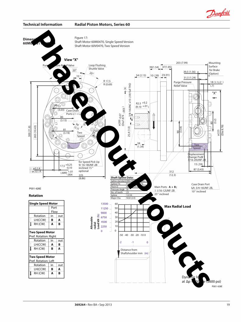
Technical Information Radial Piston Motors Series 60
369264 bull Rev BA bull Sep 2013 19
Dimensions60M0470 60V0470
Figure 17 Shaft Motor 60M0470 Single Speed VersionShaft Motor 60V0470 Two Speed Version
Single Speed MotorPortFlow
Rotation in outLH(CCW) B ARH (CW) A B
Two Speed MotorPref Rotation Right
Rotation in outLH(CCW) A BRH (CW) B A
Two Speed MotorPref Rotation Left
Rotation in outLH(CCW) B ARH (CW) A B
View X
P001 428E
TwoSpeed
L1A
B
300
(11
8)
81(319)
2020
2010
R 175R (069)
Purge Pressure Relief Valve
Case Drain Ports L1 + L2
degdeg
degdeg
Loop Flushing Shuttle Valve
L2
x1
265
(10
43)
175 +025-010
(689) +01 -004
30deg
for Speed Pick Up9 16-18UNF-2Binclined 15 degoptional
oslash05 Aoslash(02 ) A
80(315)
77(303)
94(37)
225(886)
X
P001 426E
Rotation
Max Radial Load
DisplacementChange Port X1716-20UNF-2B
Main Ports A + B 1 116-12UNF-2B25deg inclined
Case Drain Port L1 34-16UNF-2B10deg inclined
395 (156)
18 ( L1L2 )(7)
MountingSurface for Brake (Option)
Purge Pressure Relief Valve
oslash22
3(D
ia 8
78)
80 (32
)
15 (59)
90 (35
4)
315 (124)
Two Speed
23(91)10 (39)
oslash20
0-0
07
(Dia
787
4-0
03)
312(123)
203 (799)
39(154)
54 (213)
38-
16U
NC
x15
(59)
full
THD
254
(10
)
34(134)
R25 +02(R10 +01 )
87 (343)
47(185)
Shaft Spline Data5 ssalC a1129B ISNA Spline standard
Spline Fit Pitch D
03 elgnA erusserPNo of teethSplineMajor Dia
A
-50 -40 -30 -20 -10 0
-2 -1
50
60
30
40
20
0
10
Allo
wab
lera
dial
Loa
d kN
(lb
)
Distance from Shaftshoulder mm (in)
0
2250
6750
9000
11250
4500
13500
0
Dynamic loadat ∆p = 250 bar (3600 psi)
Flat Root Side Fit4863 (1916)
231224508 (20)
Phased Out Products
Technical Information Radial Piston Motors Series 60
5369264 bull Rev BA bull Sep 201320
Dimensions60M0780 60V780
Figure 18 Wheel Motor 60M0780 Single Speed VersionWheel Motor 60V0780 TwoSpeed Version
Single Speed MotorPortFlow
Rotation in outLH(CCW) B ARH (CW) A B
Two Speed MotorPref Rotation Right
Rotation in outLH(CCW) A BRH (CW) B A
Two Speed MotorPref Rotation Left
Rotation in outLH(CCW) B ARH (CW) A B
20
40
60
80
0
4500
9000
13 500
18 000
Max
Rad
ial L
oad
kN (
lb)
Dynamic load atDierential Pressure250 bar (3600 psi)
Distance from Hub Mounting Face mm (in)
-200 -150 -100 -50 0 50 100 150 200 250
-79 -6 -4 -2 0 2 4 6 8 98
oslash16
08
-02
(Dia
63
3 -0
1)
DisplacementChange Port X1716-20UNF-2B
Main Ports A + B 1 116-12UNF-2B25deg inclined
Studs 6x60 deg M18x15
15(6)
36(142)
8(31)
oslash20
5(D
ia 8
1)
oslash24
7(D
ia 9
7)
oslash26
6(D
ia 1
05)
Case Drain Port L134-16UNF-2B10deg inclined
70( L1L2 ) (276)
58 (228)
7(28)
44 (173)
MountingSurface for Brake (Option)
Purge Pressure Relief Valve
334(123)
17 (7)
195(768)
oslash25
3-0
2(D
ia 9
96
-01
)96 (38
)
72 (283)
106
(42
)
88 (35)
51(201)
104(409)
A
TwoSpeed
17(7)
View X
for Speed Pick Up9 16-18UNF-2Binclined 15 degoptional
L2L1A
B
335
(13
2)
267(1051)
R 175R (069)
Purge Pressure Relief Valve
Case Drain Ports L1 + L2
Loop Flushing Shuttle Valve
x1
TwoSpeed
300
(11
81)
175 +025-010
(689) +01 -004
oslash05 Aoslash(02 ) A
30deg
15deg15deg
15deg15deg
96(38)
93(37)
91(36)
109(43)
P001 435E
P001 436E
Rotation Radial Load Curve
X
Phased Out Products
Technical Information Radial Piston Motors Series 60
369264 bull Rev BA bull Sep 2013 21
Dimensions60M0780 60 V780
Figure 19 Flange Motor 60M0780 Single Speed VersionFlange Motor 60V0780 Two Speed Version
Single Speed MotorPortFlow
Rotation in outLH(CCW) B ARH (CW) A B
Two Speed MotorPref Rotation Right
Rotation in outLH(CCW) A BRH (CW) B A
Two Speed MotorPref Rotation Left
Rotation in outLH(CCW) B ARH (CW) A B
View X
X
Max
Rad
ial L
oad
kN (
lb)
0
20
40
60
4500
9000
13 500
0
8018 000
Distance from Hub Mounting Face mm (in)
-4 -2 0 2 6-6-79 4 8 99
-200 -100 -50 0 50 100 150 200-150 250
Dynamic loadat DierentialPressure250 bar (3600 psi)
72 (283)
DisplacementChange Port X1716-20UNF-2B
Main Ports A + B 1 116-12UNF-2B25deg inclined
Case Drain Port L134-16UNF-2B
10deg inclined
70( L1L2 )(276)
27 (106)
7(28)
44 (173)
MountingSurface for Brake (Option)
304(119)
17 (7)
25(10)
oslash25
3-0
2(D
ia 9
96
-01
)
96 (38
)
106
(42
)
88 (35)
51(201)
104(409)
Two Speed
A
oslash16
08
-02
(Dia
63
3 -0
1)
Studs 6x60 deg M18x15
15(6)
36(142)
7(3)
oslash20
5(D
ia 8
1)
oslash24
7(D
ia 9
7)
oslash26
6(D
ia 1
05)
Purge Pressure Relief Valve
164(65)
for Speed Pick Up9 16-18UNF-2Binclined 15 degoptional
L2L1A
B
335
(13
2)
267(1051)
R 175R (069)
Purge Pressure Relief Valve
Case Drain Ports L1 + L2
Loop Flushing Shuttle Valve
x1
TwoSpeed
300
(11
81)
175 +025-010
(689) +01 -004
oslash05 Aoslash(02 ) A
30deg
15deg15deg
15deg15deg
96(38)
93(37)
91(36)
109(43)
P001 436E
P001 437E
Rotation Radial Load Curve
Phased Out Products
Technical Information Radial Piston Motors Series 60
5369264 bull Rev BA bull Sep 201322
Dimensions60M0780 60V780
Figure 20 Shaft Motor 60M0780 Single Speed VersionShaft Motor 60V0780 Two Speed Version
Single Speed MotorPortFlow
Rotation in outLH(CCW) B ARH (CW) A B
Two Speed MotorPref Rotation Right
Rotation in outLH(CCW) A BRH (CW) B A
Two Speed MotorPref Rotation Left
Rotation in outLH(CCW) B ARH (CW) A B
View X
for Speed Pick Up9 16-18UNF-2Binclined 15 degoptional
L2L1A
B
335
(13
2)
267(1051)
R 175R (069)
Purge Pressure Relief Valve
Case Drain Ports L1 + L2
Loop Flushing Shuttle Valve
x1
TwoSpeed
300
(11
81)
175 +025-010
(689) +01 -004
oslash05 Aoslash(02 ) A
30deg
15deg15deg
15deg15deg
96(38)
93(37)
91(36)
109(43)
X
P001 436E
Rotation
Max Radial Load
DisplacementChange Port X1716-20UNF-2B
Main Ports A + B1 116-12UNF-2B25deg inclined
Case Drain Port L134-16UNF-2B10deg inclined
44 (173)
18 ( L1L2 ) (71)
MountingSurface for Brake (Option)
Purge Pressure Relief Valve
oslash26
7(D
ia 1
051
)96 (38
)
16 (63)
106
(42
)
37 (146)
Two Speed
25(98)16 (63)
oslash22
4-0
15
(Dia
88
19-0
06)
343(1350)
215 (846)
40(157)
70 (276)
38-
16 U
NC
x15
(59)
full
THD
381
(15
)
46(181)
R3 +02(R12 +01 )
97 (382)
54(213)
A
-100 -80 -60 -40 -20 0
-4 -2
100
60
80
40
0
20
Allo
wab
lera
dial
Loa
d kN
(lb)
Distance from Shaftshoulder mm (in)
0
9000
13500
4500
18000
0
22500
P001 438E
Dynamic load at∆p = 250 bar (3600 psi)
Shaft Spline Data5 ssalC a1129B ISNA Spline standard
Spline Fit Pitch D
03 elgnA erusserPNo of teethSplineMajor Dia
Flat Root Side Fit635 (25)
208166667 (2625)
Phased Out Products
Technical Information Radial Piston Motors Series 60
369264 bull Rev BA bull Sep 2013 23
Dimensions60M1048 60V1048
Figure 21 Wheel Motor 60M1048 Single Speed VersionWheel Motor 60V0470 Two Speed Version
Single Speed MotorPortFlow
Rotation in outLH(CCW) B ARH (CW) A B
Two Speed MotorPref Rotation Right
Rotation in outLH(CCW) A BRH (CW) B A
Two Speed MotorPref Rotation Left
Rotation in outLH(CCW) B ARH (CW) A B
View X
P001 414E
X
P001 415E
295(1161)
x110
degdeg
L1A
B
R 20 R (079)
108(425)
108(425)
Purge Pressure Relief Valve Loop Flushing Shuttle Valve
L2
TwoSpeed37
5 (1
476
)
2020
20
Case Drain Ports L1 + L2
degdeg
335
(13
19)
225 +025-010
(89) +01 -004
30deg
for Speed Pick Up9 16-18UNF-2Binclined 15 degoptional
oslash075oslash(03 )
AA
118(465)
Rotation Radial Load Curve
20
40
60
80
100
0
4500
9000
13 500
18 000
22 500
Max
Rad
ial L
oad
kN (
lb)
Distance from Hub Mounting Face mm (in)
-200 -150 -100 -50 0 50 100 150 200 250
-79 -6 -4 -2 0 2 4 6 8 98
Dynamic load atDierentialPressure250 bar (3600 psi)
Studs 5x72 deg M22x15
Case Drain Ports L1 + L2 34-16UNF-2B
66( L2 ) (260)
565(222)
Main Ports A + B 075-Code 62Split Flange Boss per SAE J 51838-16UNC-2B 22 (088) min full thread depth
8 (31)
48 (189)
MountingSurface for Brake (Option)
16(63)
47(185)
Purge Pressure Relief Valve
112(441)
379(1492)
19 (75)
220(866)
8 (31)
oslash17
58
-02
(Dia
69
2 -0
1)
oslash22
5(D
ia 8
86)
280
(Dia
11
02)oslash
292
(Dia
115
0)
508
(20
0)
285
-02
(11
22-0
1)
96 (37
8)
DisplacementChange Port X1716-20UNF-2B
79 (31)
115
(45
3)
Two Speed
96 (378)
238(94)
81( L1 )(319)
24(9)
A
Phased Out Products
Technical Information Radial Piston Motors Series 60
5369264 bull Rev BA bull Sep 201324
Dimensions60M1048 60V1048
Figure 22 Flange Motor 60M1048 Single Speed VersionFlange Motor 60V1048 Two Speed Version
Single Speed MotorPortFlow
Rotation in outLH(CCW) B ARH (CW) A B
Two Speed MotorPref Rotation Right
Rotation in outLH(CCW) A BRH (CW) B A
Two Speed MotorPref Rotation Left
Rotation in outLH(CCW) B ARH (CW) A B
View X
X
295(1161)
x1
10deg
deg
L1A
B
R 20 R (079)
108(425)
108(425)
Purge Pressure Relief Valve Loop Flushing Shuttle Valve
L2
TwoSpeed37
5 (1
476
)
2020
20
Case Drain Ports L1 + L2
degdeg
335
(13
19)
225 +025-010
(89) +01 -004
30deg
for Speed Pick Up9 16-18UNF-2Binclined 15 degoptional
oslash075oslash(03 )
AA
118(465)
Dynamic loadat DierentialPressure250 bar (3600 psi)
Max
Rad
ial L
oad
kN (
lb)
0
20
40
60
4500
9000
13 500
0
Distance from Hub Mounting Face mm (in)
-4 -2 0 2 6-6-79 4 8 99
-200 -100 -50 0 50 100 150 200-150 250
Studs 6x60 deg M18x15
Case Drain Ports L1 + L2 34-16UNF-2B
66( L2 ) (26)
255(100)
Main Ports A + B 075-Code 62Split Flange Boss per SAE J 51838-16UNC-2B 22 (088) min full thread depth
8(31)
48 (189)
MountingSurface for Brake (Option)
15(59)
36(142)
Purge Pressure Relief Valve
112(441)
322(127)
19 (75)
1745(687)
6(24)
oslash16
08
-02
(Dia
63
3 -0
1)
oslash20
5 (D
ia 8
07)
250
(Dia
98
4)
oslash29
2(D
ia11
50)
508
(20
)
285
-02
(11
22-0
1)
96 (37
8)
DisplacementChange Port X1716-20UNF-2B
79 (311)11
5 (4
53)
Two Speed
96 (378)
238(94)
81( L1 )(319)
A
255 (10)
P001 415E
Rotation Radial Load Curve
P001 416E
Phased Out Products
Technical Information Radial Piston Motors Series 60
369264 bull Rev BA bull Sep 2013 25
Dimensions60M1048 60V1048
Figure 23 Shaft Motor 60M1048 Single Speed VersionShaft Motor 60M1048 Two Speed Version
Single Speed MotorPortFlow
Rotation in outLH(CCW) B ARH (CW) A B
Two Speed MotorPref Rotation Right
Rotation in outLH(CCW) A BRH (CW) B A
Two Speed MotorPref Rotation Left
Rotation in outLH(CCW) B ARH (CW) A B
View X
295(1161)
x110
degdeg
L1A
B
R 20 R (079)
108(425)
108(425)
Purge Pressure Relief Valve Loop Flushing Shuttle Valve
L2
TwoSpeed37
5 (1
476
)
2020
20
Case Drain Ports L1 + L2
degdeg
335
(13
19)
225 +025-010
(89) +01 -004
30deg
for Speed Pick Up9 16-18UNF-2Binclined 15 degoptional
oslash075oslash(03 )
AA
118(465)
P001 415E
Rotation
Max Radial Load
X
73 ( L1 )(287)
28(110)13 (51)
oslash28
0-0
15
(Dia
110
24-0
06)
372(146)
2325 (915)
50 (197)
70 (276)
38-
16U
NC
15 (
59) f
ull T
HD
381
(15
)
46(181)
123 (484)
R 3 +02(R12 +01 )
515 (203)
Main Ports A + B 075-Code 62Split Flange Boss per SAE J 51838-16UNC-2B22 (088) min full thread depth
Case Drain Ports L1+L234-16UNF-2B
40 (157)
MountingSurface for Brake (Option)
104(41)
238(94)
508
(20
0)
oslash29
2(D
ia11
5)96 (37
8)
DisplacementChange Port X1716-20UNF-2B
17(67)
115
(45
3)
Two Speed
58( L2 )(228)
PurgePressureRelief ValveA
-100 -80 -60 -40 -20 0
-4 -2
120
60
80
40
0
20
Allo
wab
lera
dial
Loa
d kN
(lb)
Distance from Shaftshoulder mm (in)
0
9000
13500
4500
18000
0
22500 10027000
P001 417E
Dynamic load at ∆p = 250 bar (3600 psi)
Shaft Spline Data5 ssalC a1129B ISNA Spline standard
Spline Fit Pitch Dia
03 elgnA erusserPNo of teethSplineMajor Dia
Flat Root Side Fit73025 (30)
23816762 (30)
Phased Out Products
Technical Information Radial Piston Motors Series 60
5369264 bull Rev BA bull Sep 201326
Dimensions60M1750 60V1750
Figure 24 Wheel Motor 60M1750 Single Speed VersionWheel Motor 60V1750 Two Speed Version
Single Speed MotorPortFlow
Rotation in outLH(CCW) B ARH (CW) A B
Two Speed MotorPref Rotation Right
Rotation in outLH(CCW) A BRH (CW) B A
Two Speed MotorPref Rotation Left
Rotation in outLH(CCW) B ARH (CW) A B
View X
X
Rotation Radial Load Curve
P001 430E
P001 429E
L2L1A
B
425
(16
73)
Purge Pressure Relief Valve
Case Drain Ports L1 + L2
Loop Flushing Shuttle Valve
x1
Two Speed
385
(15
16)
225 +025-010
(89) +01 -004
oslash075 Aoslash(03 ) A
30deg
for Speed Pick Up9 16-18UNF-2Binclined 15 degoptional
15deg15deg
15deg15deg
350(1378)
R 20 R (079)
124(488)
124(488)
138(543)
Dynamic load atDierentialPressure250 bar (3600 psi)
(in)Distance from Hub Mounting Face mm
-200 -150 -100 -50 0 50 100 150 200 250
-79 -6 -4 -2 0 2 4 6 8 98
Max
Rad
ial L
oad
kN (
lb)
20
40
140
160
60
80
100
120
180
0
4500
9000
13 500
27 000
36 000
18 000
22 500
31 500
40 500
0
Studs 10x36 deg M22x15
Case Drain Ports L1 + L2 78-14UNF-2B
69(272)
Main Ports A + B 100-Code 62Split Flange Boss per SAE J 518716-14UNC-2B 27 (106) min full thread depth
11(43)
66 (2598)
MountingSurface for Brake (Option)
16(63)
47(185)
Purge Pressure Relief Valve
132(520)
433(1705)
225 (886)
254(100)
8 (31)
oslash17
58
-02
(Dia
69
2 -0
1)
oslash22
5(D
ia 8
86)
280
(Dia
11
02)oslash
350
(Dia
137
8)
571
5(2
25)
oslash33
0-0
2(D
ia12
992
-008
)
115
(45
28)
DisplacementChange Port X1716-20UNF-2B
99 (390)
141
(55
5)
Two Speed
116 (4567)
2776(1093)
96( L1L2 )(378)
20(0787)
A
Phased Out Products
Technical Information Radial Piston Motors Series 60
369264 bull Rev BA bull Sep 2013 27
Dimensions60M1750 60V1750
Figure 25 Flange Motor 60M1750 Single Speed VersionFlange Motor 60V1750 Two Speed Version
Single Speed MotorPortFlow
Rotation in outLH(CCW) B ARH (CW) A B
Two Speed MotorPref Rotation Right
Rotation in outLH(CCW) A BRH (CW) B A
Two Speed MotorPref Rotation Left
Rotation in outLH(CCW) B ARH (CW) A B
View X
X
P001 430E
Rotation Radial Load Curve
P001 431E
L2L1A
B
425
(16
73)
Purge Pressure Relief Valve
Case Drain Ports L1 + L2
Loop Flushing Shuttle Valve
x1
Two Speed
385
(15
16)
225 +025-010
(89) +01 -004
oslash075 Aoslash(03 ) A
30deg
for Speed Pick Up9 16-18UNF-2Binclined 15 degoptional
15deg15deg
15deg15deg
350(1378)
R 20 R (079)
124(488)
124(488)
138(543)
0
Dynamic loadat DierentialPressure250 bar (3600 psi)
Distance from Hub Mounting Face mm (in)
-6 -4 -2 0 2 64 8 99-79
-200 -100 -50 0 50 100 150 200-150 250
Max
Rad
ial L
oad
kN (
lb)
0
20
40
60
4500
9000
13 500
8018 000
10022 500
12027 000
14031 500
16036 000
18040 500
Studs 10x36 deg M22x15
Case Drain Ports L1 + L2 78-14UNF-2B
32(126)
Main Ports A + B 100-Code 62Split Flange Boss per SAE J 518716-14UNC-2B 27 (106) min full thread depth
11(43)
66 (2598)
MountingSurface for Brake (Option)
16(63)
47(185)
Purge Pressure Relief Valve
132(520)
389(1531)
225 (886)
210(1827)
8 (31)
oslash17
58
-02
(Dia
69
2 -0
1)
oslash22
5(D
ia 8
86)
280
(Dia
11
02)oslash
350
(Dia
137
8)
571
5(2
25)
oslash33
0-0
2(D
ia 1
299
2-0
08)
115
(45
28)
DisplacementChange Port X1716-20UNF-2B
99 (390)
141
(55
5)
Two Speed
116 (4567)
2776(1093)
96( L1 L2 )(378)
29 (114)
A
Phased Out Products
Technical Information Radial Piston Motors Series 60
5369264 bull Rev BA bull Sep 201328
Dimensions60M1750 60V1750
Figure 26 Shaft Motor 60M1750 Single Speed VersionShaft Motor 60V1750 Two Speed Version
Single Speed MotorPortFlow
Rotation in outLH(CCW) B ARH (CW) A B
Two Speed MotorPref Rotation Right
Rotation in outLH(CCW) A BRH (CW) B A
Two Speed MotorPref Rotation Left
Rotation in outLH(CCW) B ARH (CW) A B
View X
L2L1A
B
425
(16
73)
Purge Pressure Relief Valve
Case Drain Ports L1 + L2
Loop Flushing Shuttle Valve
x1
Two Speed
385
(15
16)
225 +025-010
(89) +01 -004
oslash075 Aoslash(03 ) A
30deg
for Speed Pick Up9 16-18UNF-2Binclined 15 degoptional
15deg15deg
15deg15deg
350(1378)
R 20 R (079)
124(488)
124(488)
138(543)
P001 430E
Rotation
X
Max Radial Load
Displacementchange Port X1716-20UNF-2B
24(94)15 (59)
oslash31
5-0
15
(Dia
124
02-0
06)
440(173)
2835 (1116)
48 (189)
90 (354)
12-
13 U
NC
X22
(86)
full
THD
381
(15
)
63(248)
141 (555)
R4 +02(R16 +01 )
97 (382)
Main Ports A + B 100-Code 62Split Flange Boss per SAE J 518716-14UNC-2B27 (106) min full thread depth
Case Drain Ports L1+L278-20UNF-2B
20 (079) ( L1+L2 )
50 (197)
MountingSurface for Brake (Option)Purge Pressure
Relief Valve
121 (48)
278(109)
572
(22
5)
oslash33
0(D
ia12
99)11
5 (4
53)
17 (67)
141
(55
5)
Two Speed
9 (35)
oslash35
0(D
ia13
78)
A
-100 -80 -60 -40 -20 0
-4 -2
200
100
150
0
50
Allo
wab
lera
dial
Loa
d kN
(lb)
Distance from Shaftshoulder mm (in)
0
22500
11250
33750
0
45000
P001 432E
Dynamic load at ∆p = 250 bar (3600 psi)
Shaft Spline Data5 ssalC a1129B ISNA Spline standard
Spline Fit Pitch Dia
03 elgnA erusserPNo of teethSplineMajor Dia
Flat Root Side Fit889 (35)
288169207 (3625)
Phased Out Products
Technical Information Radial Piston Motors Series 60
369264 bull Rev BA bull Sep 2013 29
NotesPhased Out Products
Technical Information Radial Piston Motors Series 60
5369264 bull Rev BA bull Sep 201330
DimensionsBrakes
Figure 27 Radial Piston Motor with Brake (0ptional)
P001 418E
Table 6 Brake Dimensions
Series Dimension
A B C
60M0470 23 (090) 74 (290) oslash212 (Dia 835)
60M0780 42 (165) 100 (394) oslash245 (Dia 965)
60M1048 30 (118) 90 (354) oslash280 (Dia 1102)
60M1750 38 (147) 107 (421) oslash320 (Dia 1260)
B
CX7
MountingFace
Mechanical BrakeRelease 1 to be used with Mech Brake Release 2
Mechanical BrakeRelease 2to be used with Mech Brake Release 1
A
Hydraulic BrakeRelease X7916-18UNF-2B
Mechanical BrakeRelease 1 to be used with Mech Brake Release 2
Mechanical BrakeRelease 2to be used with Mech Brake Release 1
TwoSpeed
X
View X
Phased Out Products
Technical Information Radial Piston Motors Series 60
369264 bull Rev BA bull Sep 2013 31
DimensionsSpeed Sensor
Figure 28 Radial Piston Motor with Speed Sensor (0ptional)
Section A - A (11)Speed Sensor
Connecto IdNoStraightRight angle
Connector is not supplied with the motorPlease order separatly using above Id No
Table 7 Speed Sensor Connector
Electrical details see page12
P001 444E
A
A
30deg 15 deg
31m
ax (1
22)
Pin 1Pin 2
Pin 3
Pin 4
Key Way
Wrench-Flats
Connector Insert
View Y
Y
127
(50)
500724500725
Phased Out Products
Comatrolwwwcomatrolcom
Schwarzmuumlller-Inverterwwwschwarzmueller-invertercom
Turolla wwwturollaocgcom
Valmovawwwvalmovacom
Hydro-Gear wwwhydro-gearcom
Daikin-Sauer-Danfosswwwdaikin-sauer-danfosscom
Danfoss Power Solutions is a global manufacturer and supplier of high-quality hydraulic and electronic components We specialize in providing state-of-the-art technology and solutions that excel in the harsh operating conditions of the mobile off -highway market Building on our extensive applications expertise we work closely with our customers to ensure exceptional performance for a broad range of off -highway vehicles
We help OEMs around the world speed up system development reduce costs and bring vehicles to market faster Danfoss ndash Your Strongest Partner in Mobile Hydraulics
Go to wwwpowersolutionsdanfosscom for further product information
Wherever off -highway vehicles are at work so is Danfoss
We off er expert worldwide support for our customers ensuring the best possible solutions for outstanding performance And with an extensive network of Global Service Partners we also provide comprehensive global service for all of our components
Please contact the Danfoss Power Solution representative nearest you
Products we off er
Bent Axis Motors
Closed Circuit Axial Piston Pumps and Motors
Displays
Electrohydraulic Power Steering
Electrohydraulics
Hydraulic Power Steering
Integrated Systems
Joysticks and Control Handles
Microcontrollers and Software
Open Circuit Axial Piston Pumps
Orbital Motors
PLUS+1reg GUIDE
Proportional Valves
Sensors
Steering
Transit Mixer Drives
Local address
Danfoss can accept no responsibility for possible errors in catalogues brochures and other printed material Danfoss reserves the right to alter its products without notice This also applies to products already on order provided that such alterations can be made without subsequential changes being necessary in specifications already agreedAll trademarks in this material are property of the respective companies Danfoss and the Danfoss logotype are trademarks of Danfoss AS All rights reserved
Danfoss Power Solutions22F Block C Yishan RdShanghai 200233 ChinaPhone +86 21 3418 5200
Danfoss Power Solutions GmbH amp Co OHGKrokamp 35D-24539 Neumuumlnster GermanyPhone +49 4321 871 0
Danfoss Power Solutions ApSNordborgvej 81DK-6430 Nordborg DenmarkPhone +45 7488 2222
Danfoss Power Solutions US Company2800 East 13th StreetAmes IA 50010 USAPhone +1 515 239 6000
369264 bull Rev BA bull Sep 2013 wwwdanfosscom copy Danfoss AS 2013-09
Phased Out Products
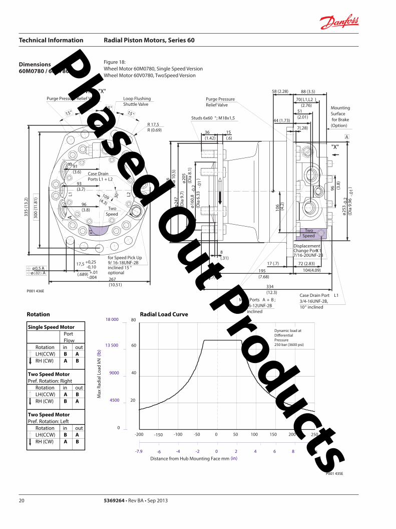
Technical Information Radial Piston Motors Series 60
5369264 bull Rev BA bull Sep 201320
Dimensions60M0780 60V780
Figure 18 Wheel Motor 60M0780 Single Speed VersionWheel Motor 60V0780 TwoSpeed Version
Single Speed MotorPortFlow
Rotation in outLH(CCW) B ARH (CW) A B
Two Speed MotorPref Rotation Right
Rotation in outLH(CCW) A BRH (CW) B A
Two Speed MotorPref Rotation Left
Rotation in outLH(CCW) B ARH (CW) A B
20
40
60
80
0
4500
9000
13 500
18 000
Max
Rad
ial L
oad
kN (
lb)
Dynamic load atDierential Pressure250 bar (3600 psi)
Distance from Hub Mounting Face mm (in)
-200 -150 -100 -50 0 50 100 150 200 250
-79 -6 -4 -2 0 2 4 6 8 98
oslash16
08
-02
(Dia
63
3 -0
1)
DisplacementChange Port X1716-20UNF-2B
Main Ports A + B 1 116-12UNF-2B25deg inclined
Studs 6x60 deg M18x15
15(6)
36(142)
8(31)
oslash20
5(D
ia 8
1)
oslash24
7(D
ia 9
7)
oslash26
6(D
ia 1
05)
Case Drain Port L134-16UNF-2B10deg inclined
70( L1L2 ) (276)
58 (228)
7(28)
44 (173)
MountingSurface for Brake (Option)
Purge Pressure Relief Valve
334(123)
17 (7)
195(768)
oslash25
3-0
2(D
ia 9
96
-01
)96 (38
)
72 (283)
106
(42
)
88 (35)
51(201)
104(409)
A
TwoSpeed
17(7)
View X
for Speed Pick Up9 16-18UNF-2Binclined 15 degoptional
L2L1A
B
335
(13
2)
267(1051)
R 175R (069)
Purge Pressure Relief Valve
Case Drain Ports L1 + L2
Loop Flushing Shuttle Valve
x1
TwoSpeed
300
(11
81)
175 +025-010
(689) +01 -004
oslash05 Aoslash(02 ) A
30deg
15deg15deg
15deg15deg
96(38)
93(37)
91(36)
109(43)
P001 435E
P001 436E
Rotation Radial Load Curve
X
Phased Out Products
Technical Information Radial Piston Motors Series 60
369264 bull Rev BA bull Sep 2013 21
Dimensions60M0780 60 V780
Figure 19 Flange Motor 60M0780 Single Speed VersionFlange Motor 60V0780 Two Speed Version
Single Speed MotorPortFlow
Rotation in outLH(CCW) B ARH (CW) A B
Two Speed MotorPref Rotation Right
Rotation in outLH(CCW) A BRH (CW) B A
Two Speed MotorPref Rotation Left
Rotation in outLH(CCW) B ARH (CW) A B
View X
X
Max
Rad
ial L
oad
kN (
lb)
0
20
40
60
4500
9000
13 500
0
8018 000
Distance from Hub Mounting Face mm (in)
-4 -2 0 2 6-6-79 4 8 99
-200 -100 -50 0 50 100 150 200-150 250
Dynamic loadat DierentialPressure250 bar (3600 psi)
72 (283)
DisplacementChange Port X1716-20UNF-2B
Main Ports A + B 1 116-12UNF-2B25deg inclined
Case Drain Port L134-16UNF-2B
10deg inclined
70( L1L2 )(276)
27 (106)
7(28)
44 (173)
MountingSurface for Brake (Option)
304(119)
17 (7)
25(10)
oslash25
3-0
2(D
ia 9
96
-01
)
96 (38
)
106
(42
)
88 (35)
51(201)
104(409)
Two Speed
A
oslash16
08
-02
(Dia
63
3 -0
1)
Studs 6x60 deg M18x15
15(6)
36(142)
7(3)
oslash20
5(D
ia 8
1)
oslash24
7(D
ia 9
7)
oslash26
6(D
ia 1
05)
Purge Pressure Relief Valve
164(65)
for Speed Pick Up9 16-18UNF-2Binclined 15 degoptional
L2L1A
B
335
(13
2)
267(1051)
R 175R (069)
Purge Pressure Relief Valve
Case Drain Ports L1 + L2
Loop Flushing Shuttle Valve
x1
TwoSpeed
300
(11
81)
175 +025-010
(689) +01 -004
oslash05 Aoslash(02 ) A
30deg
15deg15deg
15deg15deg
96(38)
93(37)
91(36)
109(43)
P001 436E
P001 437E
Rotation Radial Load Curve
Phased Out Products
Technical Information Radial Piston Motors Series 60
5369264 bull Rev BA bull Sep 201322
Dimensions60M0780 60V780
Figure 20 Shaft Motor 60M0780 Single Speed VersionShaft Motor 60V0780 Two Speed Version
Single Speed MotorPortFlow
Rotation in outLH(CCW) B ARH (CW) A B
Two Speed MotorPref Rotation Right
Rotation in outLH(CCW) A BRH (CW) B A
Two Speed MotorPref Rotation Left
Rotation in outLH(CCW) B ARH (CW) A B
View X
for Speed Pick Up9 16-18UNF-2Binclined 15 degoptional
L2L1A
B
335
(13
2)
267(1051)
R 175R (069)
Purge Pressure Relief Valve
Case Drain Ports L1 + L2
Loop Flushing Shuttle Valve
x1
TwoSpeed
300
(11
81)
175 +025-010
(689) +01 -004
oslash05 Aoslash(02 ) A
30deg
15deg15deg
15deg15deg
96(38)
93(37)
91(36)
109(43)
X
P001 436E
Rotation
Max Radial Load
DisplacementChange Port X1716-20UNF-2B
Main Ports A + B1 116-12UNF-2B25deg inclined
Case Drain Port L134-16UNF-2B10deg inclined
44 (173)
18 ( L1L2 ) (71)
MountingSurface for Brake (Option)
Purge Pressure Relief Valve
oslash26
7(D
ia 1
051
)96 (38
)
16 (63)
106
(42
)
37 (146)
Two Speed
25(98)16 (63)
oslash22
4-0
15
(Dia
88
19-0
06)
343(1350)
215 (846)
40(157)
70 (276)
38-
16 U
NC
x15
(59)
full
THD
381
(15
)
46(181)
R3 +02(R12 +01 )
97 (382)
54(213)
A
-100 -80 -60 -40 -20 0
-4 -2
100
60
80
40
0
20
Allo
wab
lera
dial
Loa
d kN
(lb)
Distance from Shaftshoulder mm (in)
0
9000
13500
4500
18000
0
22500
P001 438E
Dynamic load at∆p = 250 bar (3600 psi)
Shaft Spline Data5 ssalC a1129B ISNA Spline standard
Spline Fit Pitch D
03 elgnA erusserPNo of teethSplineMajor Dia
Flat Root Side Fit635 (25)
208166667 (2625)
Phased Out Products
Technical Information Radial Piston Motors Series 60
369264 bull Rev BA bull Sep 2013 23
Dimensions60M1048 60V1048
Figure 21 Wheel Motor 60M1048 Single Speed VersionWheel Motor 60V0470 Two Speed Version
Single Speed MotorPortFlow
Rotation in outLH(CCW) B ARH (CW) A B
Two Speed MotorPref Rotation Right
Rotation in outLH(CCW) A BRH (CW) B A
Two Speed MotorPref Rotation Left
Rotation in outLH(CCW) B ARH (CW) A B
View X
P001 414E
X
P001 415E
295(1161)
x110
degdeg
L1A
B
R 20 R (079)
108(425)
108(425)
Purge Pressure Relief Valve Loop Flushing Shuttle Valve
L2
TwoSpeed37
5 (1
476
)
2020
20
Case Drain Ports L1 + L2
degdeg
335
(13
19)
225 +025-010
(89) +01 -004
30deg
for Speed Pick Up9 16-18UNF-2Binclined 15 degoptional
oslash075oslash(03 )
AA
118(465)
Rotation Radial Load Curve
20
40
60
80
100
0
4500
9000
13 500
18 000
22 500
Max
Rad
ial L
oad
kN (
lb)
Distance from Hub Mounting Face mm (in)
-200 -150 -100 -50 0 50 100 150 200 250
-79 -6 -4 -2 0 2 4 6 8 98
Dynamic load atDierentialPressure250 bar (3600 psi)
Studs 5x72 deg M22x15
Case Drain Ports L1 + L2 34-16UNF-2B
66( L2 ) (260)
565(222)
Main Ports A + B 075-Code 62Split Flange Boss per SAE J 51838-16UNC-2B 22 (088) min full thread depth
8 (31)
48 (189)
MountingSurface for Brake (Option)
16(63)
47(185)
Purge Pressure Relief Valve
112(441)
379(1492)
19 (75)
220(866)
8 (31)
oslash17
58
-02
(Dia
69
2 -0
1)
oslash22
5(D
ia 8
86)
280
(Dia
11
02)oslash
292
(Dia
115
0)
508
(20
0)
285
-02
(11
22-0
1)
96 (37
8)
DisplacementChange Port X1716-20UNF-2B
79 (31)
115
(45
3)
Two Speed
96 (378)
238(94)
81( L1 )(319)
24(9)
A
Phased Out Products
Technical Information Radial Piston Motors Series 60
5369264 bull Rev BA bull Sep 201324
Dimensions60M1048 60V1048
Figure 22 Flange Motor 60M1048 Single Speed VersionFlange Motor 60V1048 Two Speed Version
Single Speed MotorPortFlow
Rotation in outLH(CCW) B ARH (CW) A B
Two Speed MotorPref Rotation Right
Rotation in outLH(CCW) A BRH (CW) B A
Two Speed MotorPref Rotation Left
Rotation in outLH(CCW) B ARH (CW) A B
View X
X
295(1161)
x1
10deg
deg
L1A
B
R 20 R (079)
108(425)
108(425)
Purge Pressure Relief Valve Loop Flushing Shuttle Valve
L2
TwoSpeed37
5 (1
476
)
2020
20
Case Drain Ports L1 + L2
degdeg
335
(13
19)
225 +025-010
(89) +01 -004
30deg
for Speed Pick Up9 16-18UNF-2Binclined 15 degoptional
oslash075oslash(03 )
AA
118(465)
Dynamic loadat DierentialPressure250 bar (3600 psi)
Max
Rad
ial L
oad
kN (
lb)
0
20
40
60
4500
9000
13 500
0
Distance from Hub Mounting Face mm (in)
-4 -2 0 2 6-6-79 4 8 99
-200 -100 -50 0 50 100 150 200-150 250
Studs 6x60 deg M18x15
Case Drain Ports L1 + L2 34-16UNF-2B
66( L2 ) (26)
255(100)
Main Ports A + B 075-Code 62Split Flange Boss per SAE J 51838-16UNC-2B 22 (088) min full thread depth
8(31)
48 (189)
MountingSurface for Brake (Option)
15(59)
36(142)
Purge Pressure Relief Valve
112(441)
322(127)
19 (75)
1745(687)
6(24)
oslash16
08
-02
(Dia
63
3 -0
1)
oslash20
5 (D
ia 8
07)
250
(Dia
98
4)
oslash29
2(D
ia11
50)
508
(20
)
285
-02
(11
22-0
1)
96 (37
8)
DisplacementChange Port X1716-20UNF-2B
79 (311)11
5 (4
53)
Two Speed
96 (378)
238(94)
81( L1 )(319)
A
255 (10)
P001 415E
Rotation Radial Load Curve
P001 416E
Phased Out Products
Technical Information Radial Piston Motors Series 60
369264 bull Rev BA bull Sep 2013 25
Dimensions60M1048 60V1048
Figure 23 Shaft Motor 60M1048 Single Speed VersionShaft Motor 60M1048 Two Speed Version
Single Speed MotorPortFlow
Rotation in outLH(CCW) B ARH (CW) A B
Two Speed MotorPref Rotation Right
Rotation in outLH(CCW) A BRH (CW) B A
Two Speed MotorPref Rotation Left
Rotation in outLH(CCW) B ARH (CW) A B
View X
295(1161)
x110
degdeg
L1A
B
R 20 R (079)
108(425)
108(425)
Purge Pressure Relief Valve Loop Flushing Shuttle Valve
L2
TwoSpeed37
5 (1
476
)
2020
20
Case Drain Ports L1 + L2
degdeg
335
(13
19)
225 +025-010
(89) +01 -004
30deg
for Speed Pick Up9 16-18UNF-2Binclined 15 degoptional
oslash075oslash(03 )
AA
118(465)
P001 415E
Rotation
Max Radial Load
X
73 ( L1 )(287)
28(110)13 (51)
oslash28
0-0
15
(Dia
110
24-0
06)
372(146)
2325 (915)
50 (197)
70 (276)
38-
16U
NC
15 (
59) f
ull T
HD
381
(15
)
46(181)
123 (484)
R 3 +02(R12 +01 )
515 (203)
Main Ports A + B 075-Code 62Split Flange Boss per SAE J 51838-16UNC-2B22 (088) min full thread depth
Case Drain Ports L1+L234-16UNF-2B
40 (157)
MountingSurface for Brake (Option)
104(41)
238(94)
508
(20
0)
oslash29
2(D
ia11
5)96 (37
8)
DisplacementChange Port X1716-20UNF-2B
17(67)
115
(45
3)
Two Speed
58( L2 )(228)
PurgePressureRelief ValveA
-100 -80 -60 -40 -20 0
-4 -2
120
60
80
40
0
20
Allo
wab
lera
dial
Loa
d kN
(lb)
Distance from Shaftshoulder mm (in)
0
9000
13500
4500
18000
0
22500 10027000
P001 417E
Dynamic load at ∆p = 250 bar (3600 psi)
Shaft Spline Data5 ssalC a1129B ISNA Spline standard
Spline Fit Pitch Dia
03 elgnA erusserPNo of teethSplineMajor Dia
Flat Root Side Fit73025 (30)
23816762 (30)
Phased Out Products
Technical Information Radial Piston Motors Series 60
5369264 bull Rev BA bull Sep 201326
Dimensions60M1750 60V1750
Figure 24 Wheel Motor 60M1750 Single Speed VersionWheel Motor 60V1750 Two Speed Version
Single Speed MotorPortFlow
Rotation in outLH(CCW) B ARH (CW) A B
Two Speed MotorPref Rotation Right
Rotation in outLH(CCW) A BRH (CW) B A
Two Speed MotorPref Rotation Left
Rotation in outLH(CCW) B ARH (CW) A B
View X
X
Rotation Radial Load Curve
P001 430E
P001 429E
L2L1A
B
425
(16
73)
Purge Pressure Relief Valve
Case Drain Ports L1 + L2
Loop Flushing Shuttle Valve
x1
Two Speed
385
(15
16)
225 +025-010
(89) +01 -004
oslash075 Aoslash(03 ) A
30deg
for Speed Pick Up9 16-18UNF-2Binclined 15 degoptional
15deg15deg
15deg15deg
350(1378)
R 20 R (079)
124(488)
124(488)
138(543)
Dynamic load atDierentialPressure250 bar (3600 psi)
(in)Distance from Hub Mounting Face mm
-200 -150 -100 -50 0 50 100 150 200 250
-79 -6 -4 -2 0 2 4 6 8 98
Max
Rad
ial L
oad
kN (
lb)
20
40
140
160
60
80
100
120
180
0
4500
9000
13 500
27 000
36 000
18 000
22 500
31 500
40 500
0
Studs 10x36 deg M22x15
Case Drain Ports L1 + L2 78-14UNF-2B
69(272)
Main Ports A + B 100-Code 62Split Flange Boss per SAE J 518716-14UNC-2B 27 (106) min full thread depth
11(43)
66 (2598)
MountingSurface for Brake (Option)
16(63)
47(185)
Purge Pressure Relief Valve
132(520)
433(1705)
225 (886)
254(100)
8 (31)
oslash17
58
-02
(Dia
69
2 -0
1)
oslash22
5(D
ia 8
86)
280
(Dia
11
02)oslash
350
(Dia
137
8)
571
5(2
25)
oslash33
0-0
2(D
ia12
992
-008
)
115
(45
28)
DisplacementChange Port X1716-20UNF-2B
99 (390)
141
(55
5)
Two Speed
116 (4567)
2776(1093)
96( L1L2 )(378)
20(0787)
A
Phased Out Products
Technical Information Radial Piston Motors Series 60
369264 bull Rev BA bull Sep 2013 27
Dimensions60M1750 60V1750
Figure 25 Flange Motor 60M1750 Single Speed VersionFlange Motor 60V1750 Two Speed Version
Single Speed MotorPortFlow
Rotation in outLH(CCW) B ARH (CW) A B
Two Speed MotorPref Rotation Right
Rotation in outLH(CCW) A BRH (CW) B A
Two Speed MotorPref Rotation Left
Rotation in outLH(CCW) B ARH (CW) A B
View X
X
P001 430E
Rotation Radial Load Curve
P001 431E
L2L1A
B
425
(16
73)
Purge Pressure Relief Valve
Case Drain Ports L1 + L2
Loop Flushing Shuttle Valve
x1
Two Speed
385
(15
16)
225 +025-010
(89) +01 -004
oslash075 Aoslash(03 ) A
30deg
for Speed Pick Up9 16-18UNF-2Binclined 15 degoptional
15deg15deg
15deg15deg
350(1378)
R 20 R (079)
124(488)
124(488)
138(543)
0
Dynamic loadat DierentialPressure250 bar (3600 psi)
Distance from Hub Mounting Face mm (in)
-6 -4 -2 0 2 64 8 99-79
-200 -100 -50 0 50 100 150 200-150 250
Max
Rad
ial L
oad
kN (
lb)
0
20
40
60
4500
9000
13 500
8018 000
10022 500
12027 000
14031 500
16036 000
18040 500
Studs 10x36 deg M22x15
Case Drain Ports L1 + L2 78-14UNF-2B
32(126)
Main Ports A + B 100-Code 62Split Flange Boss per SAE J 518716-14UNC-2B 27 (106) min full thread depth
11(43)
66 (2598)
MountingSurface for Brake (Option)
16(63)
47(185)
Purge Pressure Relief Valve
132(520)
389(1531)
225 (886)
210(1827)
8 (31)
oslash17
58
-02
(Dia
69
2 -0
1)
oslash22
5(D
ia 8
86)
280
(Dia
11
02)oslash
350
(Dia
137
8)
571
5(2
25)
oslash33
0-0
2(D
ia 1
299
2-0
08)
115
(45
28)
DisplacementChange Port X1716-20UNF-2B
99 (390)
141
(55
5)
Two Speed
116 (4567)
2776(1093)
96( L1 L2 )(378)
29 (114)
A
Phased Out Products
Technical Information Radial Piston Motors Series 60
5369264 bull Rev BA bull Sep 201328
Dimensions60M1750 60V1750
Figure 26 Shaft Motor 60M1750 Single Speed VersionShaft Motor 60V1750 Two Speed Version
Single Speed MotorPortFlow
Rotation in outLH(CCW) B ARH (CW) A B
Two Speed MotorPref Rotation Right
Rotation in outLH(CCW) A BRH (CW) B A
Two Speed MotorPref Rotation Left
Rotation in outLH(CCW) B ARH (CW) A B
View X
L2L1A
B
425
(16
73)
Purge Pressure Relief Valve
Case Drain Ports L1 + L2
Loop Flushing Shuttle Valve
x1
Two Speed
385
(15
16)
225 +025-010
(89) +01 -004
oslash075 Aoslash(03 ) A
30deg
for Speed Pick Up9 16-18UNF-2Binclined 15 degoptional
15deg15deg
15deg15deg
350(1378)
R 20 R (079)
124(488)
124(488)
138(543)
P001 430E
Rotation
X
Max Radial Load
Displacementchange Port X1716-20UNF-2B
24(94)15 (59)
oslash31
5-0
15
(Dia
124
02-0
06)
440(173)
2835 (1116)
48 (189)
90 (354)
12-
13 U
NC
X22
(86)
full
THD
381
(15
)
63(248)
141 (555)
R4 +02(R16 +01 )
97 (382)
Main Ports A + B 100-Code 62Split Flange Boss per SAE J 518716-14UNC-2B27 (106) min full thread depth
Case Drain Ports L1+L278-20UNF-2B
20 (079) ( L1+L2 )
50 (197)
MountingSurface for Brake (Option)Purge Pressure
Relief Valve
121 (48)
278(109)
572
(22
5)
oslash33
0(D
ia12
99)11
5 (4
53)
17 (67)
141
(55
5)
Two Speed
9 (35)
oslash35
0(D
ia13
78)
A
-100 -80 -60 -40 -20 0
-4 -2
200
100
150
0
50
Allo
wab
lera
dial
Loa
d kN
(lb)
Distance from Shaftshoulder mm (in)
0
22500
11250
33750
0
45000
P001 432E
Dynamic load at ∆p = 250 bar (3600 psi)
Shaft Spline Data5 ssalC a1129B ISNA Spline standard
Spline Fit Pitch Dia
03 elgnA erusserPNo of teethSplineMajor Dia
Flat Root Side Fit889 (35)
288169207 (3625)
Phased Out Products
Technical Information Radial Piston Motors Series 60
369264 bull Rev BA bull Sep 2013 29
NotesPhased Out Products
Technical Information Radial Piston Motors Series 60
5369264 bull Rev BA bull Sep 201330
DimensionsBrakes
Figure 27 Radial Piston Motor with Brake (0ptional)
P001 418E
Table 6 Brake Dimensions
Series Dimension
A B C
60M0470 23 (090) 74 (290) oslash212 (Dia 835)
60M0780 42 (165) 100 (394) oslash245 (Dia 965)
60M1048 30 (118) 90 (354) oslash280 (Dia 1102)
60M1750 38 (147) 107 (421) oslash320 (Dia 1260)
B
CX7
MountingFace
Mechanical BrakeRelease 1 to be used with Mech Brake Release 2
Mechanical BrakeRelease 2to be used with Mech Brake Release 1
A
Hydraulic BrakeRelease X7916-18UNF-2B
Mechanical BrakeRelease 1 to be used with Mech Brake Release 2
Mechanical BrakeRelease 2to be used with Mech Brake Release 1
TwoSpeed
X
View X
Phased Out Products
Technical Information Radial Piston Motors Series 60
369264 bull Rev BA bull Sep 2013 31
DimensionsSpeed Sensor
Figure 28 Radial Piston Motor with Speed Sensor (0ptional)
Section A - A (11)Speed Sensor
Connecto IdNoStraightRight angle
Connector is not supplied with the motorPlease order separatly using above Id No
Table 7 Speed Sensor Connector
Electrical details see page12
P001 444E
A
A
30deg 15 deg
31m
ax (1
22)
Pin 1Pin 2
Pin 3
Pin 4
Key Way
Wrench-Flats
Connector Insert
View Y
Y
127
(50)
500724500725
Phased Out Products
Comatrolwwwcomatrolcom
Schwarzmuumlller-Inverterwwwschwarzmueller-invertercom
Turolla wwwturollaocgcom
Valmovawwwvalmovacom
Hydro-Gear wwwhydro-gearcom
Daikin-Sauer-Danfosswwwdaikin-sauer-danfosscom
Danfoss Power Solutions is a global manufacturer and supplier of high-quality hydraulic and electronic components We specialize in providing state-of-the-art technology and solutions that excel in the harsh operating conditions of the mobile off -highway market Building on our extensive applications expertise we work closely with our customers to ensure exceptional performance for a broad range of off -highway vehicles
We help OEMs around the world speed up system development reduce costs and bring vehicles to market faster Danfoss ndash Your Strongest Partner in Mobile Hydraulics
Go to wwwpowersolutionsdanfosscom for further product information
Wherever off -highway vehicles are at work so is Danfoss
We off er expert worldwide support for our customers ensuring the best possible solutions for outstanding performance And with an extensive network of Global Service Partners we also provide comprehensive global service for all of our components
Please contact the Danfoss Power Solution representative nearest you
Products we off er
Bent Axis Motors
Closed Circuit Axial Piston Pumps and Motors
Displays
Electrohydraulic Power Steering
Electrohydraulics
Hydraulic Power Steering
Integrated Systems
Joysticks and Control Handles
Microcontrollers and Software
Open Circuit Axial Piston Pumps
Orbital Motors
PLUS+1reg GUIDE
Proportional Valves
Sensors
Steering
Transit Mixer Drives
Local address
Danfoss can accept no responsibility for possible errors in catalogues brochures and other printed material Danfoss reserves the right to alter its products without notice This also applies to products already on order provided that such alterations can be made without subsequential changes being necessary in specifications already agreedAll trademarks in this material are property of the respective companies Danfoss and the Danfoss logotype are trademarks of Danfoss AS All rights reserved
Danfoss Power Solutions22F Block C Yishan RdShanghai 200233 ChinaPhone +86 21 3418 5200
Danfoss Power Solutions GmbH amp Co OHGKrokamp 35D-24539 Neumuumlnster GermanyPhone +49 4321 871 0
Danfoss Power Solutions ApSNordborgvej 81DK-6430 Nordborg DenmarkPhone +45 7488 2222
Danfoss Power Solutions US Company2800 East 13th StreetAmes IA 50010 USAPhone +1 515 239 6000
369264 bull Rev BA bull Sep 2013 wwwdanfosscom copy Danfoss AS 2013-09
Phased Out Products
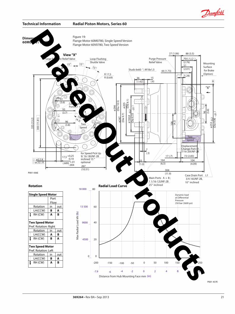
Technical Information Radial Piston Motors Series 60
369264 bull Rev BA bull Sep 2013 21
Dimensions60M0780 60 V780
Figure 19 Flange Motor 60M0780 Single Speed VersionFlange Motor 60V0780 Two Speed Version
Single Speed MotorPortFlow
Rotation in outLH(CCW) B ARH (CW) A B
Two Speed MotorPref Rotation Right
Rotation in outLH(CCW) A BRH (CW) B A
Two Speed MotorPref Rotation Left
Rotation in outLH(CCW) B ARH (CW) A B
View X
X
Max
Rad
ial L
oad
kN (
lb)
0
20
40
60
4500
9000
13 500
0
8018 000
Distance from Hub Mounting Face mm (in)
-4 -2 0 2 6-6-79 4 8 99
-200 -100 -50 0 50 100 150 200-150 250
Dynamic loadat DierentialPressure250 bar (3600 psi)
72 (283)
DisplacementChange Port X1716-20UNF-2B
Main Ports A + B 1 116-12UNF-2B25deg inclined
Case Drain Port L134-16UNF-2B
10deg inclined
70( L1L2 )(276)
27 (106)
7(28)
44 (173)
MountingSurface for Brake (Option)
304(119)
17 (7)
25(10)
oslash25
3-0
2(D
ia 9
96
-01
)
96 (38
)
106
(42
)
88 (35)
51(201)
104(409)
Two Speed
A
oslash16
08
-02
(Dia
63
3 -0
1)
Studs 6x60 deg M18x15
15(6)
36(142)
7(3)
oslash20
5(D
ia 8
1)
oslash24
7(D
ia 9
7)
oslash26
6(D
ia 1
05)
Purge Pressure Relief Valve
164(65)
for Speed Pick Up9 16-18UNF-2Binclined 15 degoptional
L2L1A
B
335
(13
2)
267(1051)
R 175R (069)
Purge Pressure Relief Valve
Case Drain Ports L1 + L2
Loop Flushing Shuttle Valve
x1
TwoSpeed
300
(11
81)
175 +025-010
(689) +01 -004
oslash05 Aoslash(02 ) A
30deg
15deg15deg
15deg15deg
96(38)
93(37)
91(36)
109(43)
P001 436E
P001 437E
Rotation Radial Load Curve
Phased Out Products
Technical Information Radial Piston Motors Series 60
5369264 bull Rev BA bull Sep 201322
Dimensions60M0780 60V780
Figure 20 Shaft Motor 60M0780 Single Speed VersionShaft Motor 60V0780 Two Speed Version
Single Speed MotorPortFlow
Rotation in outLH(CCW) B ARH (CW) A B
Two Speed MotorPref Rotation Right
Rotation in outLH(CCW) A BRH (CW) B A
Two Speed MotorPref Rotation Left
Rotation in outLH(CCW) B ARH (CW) A B
View X
for Speed Pick Up9 16-18UNF-2Binclined 15 degoptional
L2L1A
B
335
(13
2)
267(1051)
R 175R (069)
Purge Pressure Relief Valve
Case Drain Ports L1 + L2
Loop Flushing Shuttle Valve
x1
TwoSpeed
300
(11
81)
175 +025-010
(689) +01 -004
oslash05 Aoslash(02 ) A
30deg
15deg15deg
15deg15deg
96(38)
93(37)
91(36)
109(43)
X
P001 436E
Rotation
Max Radial Load
DisplacementChange Port X1716-20UNF-2B
Main Ports A + B1 116-12UNF-2B25deg inclined
Case Drain Port L134-16UNF-2B10deg inclined
44 (173)
18 ( L1L2 ) (71)
MountingSurface for Brake (Option)
Purge Pressure Relief Valve
oslash26
7(D
ia 1
051
)96 (38
)
16 (63)
106
(42
)
37 (146)
Two Speed
25(98)16 (63)
oslash22
4-0
15
(Dia
88
19-0
06)
343(1350)
215 (846)
40(157)
70 (276)
38-
16 U
NC
x15
(59)
full
THD
381
(15
)
46(181)
R3 +02(R12 +01 )
97 (382)
54(213)
A
-100 -80 -60 -40 -20 0
-4 -2
100
60
80
40
0
20
Allo
wab
lera
dial
Loa
d kN
(lb)
Distance from Shaftshoulder mm (in)
0
9000
13500
4500
18000
0
22500
P001 438E
Dynamic load at∆p = 250 bar (3600 psi)
Shaft Spline Data5 ssalC a1129B ISNA Spline standard
Spline Fit Pitch D
03 elgnA erusserPNo of teethSplineMajor Dia
Flat Root Side Fit635 (25)
208166667 (2625)
Phased Out Products
Technical Information Radial Piston Motors Series 60
369264 bull Rev BA bull Sep 2013 23
Dimensions60M1048 60V1048
Figure 21 Wheel Motor 60M1048 Single Speed VersionWheel Motor 60V0470 Two Speed Version
Single Speed MotorPortFlow
Rotation in outLH(CCW) B ARH (CW) A B
Two Speed MotorPref Rotation Right
Rotation in outLH(CCW) A BRH (CW) B A
Two Speed MotorPref Rotation Left
Rotation in outLH(CCW) B ARH (CW) A B
View X
P001 414E
X
P001 415E
295(1161)
x110
degdeg
L1A
B
R 20 R (079)
108(425)
108(425)
Purge Pressure Relief Valve Loop Flushing Shuttle Valve
L2
TwoSpeed37
5 (1
476
)
2020
20
Case Drain Ports L1 + L2
degdeg
335
(13
19)
225 +025-010
(89) +01 -004
30deg
for Speed Pick Up9 16-18UNF-2Binclined 15 degoptional
oslash075oslash(03 )
AA
118(465)
Rotation Radial Load Curve
20
40
60
80
100
0
4500
9000
13 500
18 000
22 500
Max
Rad
ial L
oad
kN (
lb)
Distance from Hub Mounting Face mm (in)
-200 -150 -100 -50 0 50 100 150 200 250
-79 -6 -4 -2 0 2 4 6 8 98
Dynamic load atDierentialPressure250 bar (3600 psi)
Studs 5x72 deg M22x15
Case Drain Ports L1 + L2 34-16UNF-2B
66( L2 ) (260)
565(222)
Main Ports A + B 075-Code 62Split Flange Boss per SAE J 51838-16UNC-2B 22 (088) min full thread depth
8 (31)
48 (189)
MountingSurface for Brake (Option)
16(63)
47(185)
Purge Pressure Relief Valve
112(441)
379(1492)
19 (75)
220(866)
8 (31)
oslash17
58
-02
(Dia
69
2 -0
1)
oslash22
5(D
ia 8
86)
280
(Dia
11
02)oslash
292
(Dia
115
0)
508
(20
0)
285
-02
(11
22-0
1)
96 (37
8)
DisplacementChange Port X1716-20UNF-2B
79 (31)
115
(45
3)
Two Speed
96 (378)
238(94)
81( L1 )(319)
24(9)
A
Phased Out Products
Technical Information Radial Piston Motors Series 60
5369264 bull Rev BA bull Sep 201324
Dimensions60M1048 60V1048
Figure 22 Flange Motor 60M1048 Single Speed VersionFlange Motor 60V1048 Two Speed Version
Single Speed MotorPortFlow
Rotation in outLH(CCW) B ARH (CW) A B
Two Speed MotorPref Rotation Right
Rotation in outLH(CCW) A BRH (CW) B A
Two Speed MotorPref Rotation Left
Rotation in outLH(CCW) B ARH (CW) A B
View X
X
295(1161)
x1
10deg
deg
L1A
B
R 20 R (079)
108(425)
108(425)
Purge Pressure Relief Valve Loop Flushing Shuttle Valve
L2
TwoSpeed37
5 (1
476
)
2020
20
Case Drain Ports L1 + L2
degdeg
335
(13
19)
225 +025-010
(89) +01 -004
30deg
for Speed Pick Up9 16-18UNF-2Binclined 15 degoptional
oslash075oslash(03 )
AA
118(465)
Dynamic loadat DierentialPressure250 bar (3600 psi)
Max
Rad
ial L
oad
kN (
lb)
0
20
40
60
4500
9000
13 500
0
Distance from Hub Mounting Face mm (in)
-4 -2 0 2 6-6-79 4 8 99
-200 -100 -50 0 50 100 150 200-150 250
Studs 6x60 deg M18x15
Case Drain Ports L1 + L2 34-16UNF-2B
66( L2 ) (26)
255(100)
Main Ports A + B 075-Code 62Split Flange Boss per SAE J 51838-16UNC-2B 22 (088) min full thread depth
8(31)
48 (189)
MountingSurface for Brake (Option)
15(59)
36(142)
Purge Pressure Relief Valve
112(441)
322(127)
19 (75)
1745(687)
6(24)
oslash16
08
-02
(Dia
63
3 -0
1)
oslash20
5 (D
ia 8
07)
250
(Dia
98
4)
oslash29
2(D
ia11
50)
508
(20
)
285
-02
(11
22-0
1)
96 (37
8)
DisplacementChange Port X1716-20UNF-2B
79 (311)11
5 (4
53)
Two Speed
96 (378)
238(94)
81( L1 )(319)
A
255 (10)
P001 415E
Rotation Radial Load Curve
P001 416E
Phased Out Products
Technical Information Radial Piston Motors Series 60
369264 bull Rev BA bull Sep 2013 25
Dimensions60M1048 60V1048
Figure 23 Shaft Motor 60M1048 Single Speed VersionShaft Motor 60M1048 Two Speed Version
Single Speed MotorPortFlow
Rotation in outLH(CCW) B ARH (CW) A B
Two Speed MotorPref Rotation Right
Rotation in outLH(CCW) A BRH (CW) B A
Two Speed MotorPref Rotation Left
Rotation in outLH(CCW) B ARH (CW) A B
View X
295(1161)
x110
degdeg
L1A
B
R 20 R (079)
108(425)
108(425)
Purge Pressure Relief Valve Loop Flushing Shuttle Valve
L2
TwoSpeed37
5 (1
476
)
2020
20
Case Drain Ports L1 + L2
degdeg
335
(13
19)
225 +025-010
(89) +01 -004
30deg
for Speed Pick Up9 16-18UNF-2Binclined 15 degoptional
oslash075oslash(03 )
AA
118(465)
P001 415E
Rotation
Max Radial Load
X
73 ( L1 )(287)
28(110)13 (51)
oslash28
0-0
15
(Dia
110
24-0
06)
372(146)
2325 (915)
50 (197)
70 (276)
38-
16U
NC
15 (
59) f
ull T
HD
381
(15
)
46(181)
123 (484)
R 3 +02(R12 +01 )
515 (203)
Main Ports A + B 075-Code 62Split Flange Boss per SAE J 51838-16UNC-2B22 (088) min full thread depth
Case Drain Ports L1+L234-16UNF-2B
40 (157)
MountingSurface for Brake (Option)
104(41)
238(94)
508
(20
0)
oslash29
2(D
ia11
5)96 (37
8)
DisplacementChange Port X1716-20UNF-2B
17(67)
115
(45
3)
Two Speed
58( L2 )(228)
PurgePressureRelief ValveA
-100 -80 -60 -40 -20 0
-4 -2
120
60
80
40
0
20
Allo
wab
lera
dial
Loa
d kN
(lb)
Distance from Shaftshoulder mm (in)
0
9000
13500
4500
18000
0
22500 10027000
P001 417E
Dynamic load at ∆p = 250 bar (3600 psi)
Shaft Spline Data5 ssalC a1129B ISNA Spline standard
Spline Fit Pitch Dia
03 elgnA erusserPNo of teethSplineMajor Dia
Flat Root Side Fit73025 (30)
23816762 (30)
Phased Out Products
Technical Information Radial Piston Motors Series 60
5369264 bull Rev BA bull Sep 201326
Dimensions60M1750 60V1750
Figure 24 Wheel Motor 60M1750 Single Speed VersionWheel Motor 60V1750 Two Speed Version
Single Speed MotorPortFlow
Rotation in outLH(CCW) B ARH (CW) A B
Two Speed MotorPref Rotation Right
Rotation in outLH(CCW) A BRH (CW) B A
Two Speed MotorPref Rotation Left
Rotation in outLH(CCW) B ARH (CW) A B
View X
X
Rotation Radial Load Curve
P001 430E
P001 429E
L2L1A
B
425
(16
73)
Purge Pressure Relief Valve
Case Drain Ports L1 + L2
Loop Flushing Shuttle Valve
x1
Two Speed
385
(15
16)
225 +025-010
(89) +01 -004
oslash075 Aoslash(03 ) A
30deg
for Speed Pick Up9 16-18UNF-2Binclined 15 degoptional
15deg15deg
15deg15deg
350(1378)
R 20 R (079)
124(488)
124(488)
138(543)
Dynamic load atDierentialPressure250 bar (3600 psi)
(in)Distance from Hub Mounting Face mm
-200 -150 -100 -50 0 50 100 150 200 250
-79 -6 -4 -2 0 2 4 6 8 98
Max
Rad
ial L
oad
kN (
lb)
20
40
140
160
60
80
100
120
180
0
4500
9000
13 500
27 000
36 000
18 000
22 500
31 500
40 500
0
Studs 10x36 deg M22x15
Case Drain Ports L1 + L2 78-14UNF-2B
69(272)
Main Ports A + B 100-Code 62Split Flange Boss per SAE J 518716-14UNC-2B 27 (106) min full thread depth
11(43)
66 (2598)
MountingSurface for Brake (Option)
16(63)
47(185)
Purge Pressure Relief Valve
132(520)
433(1705)
225 (886)
254(100)
8 (31)
oslash17
58
-02
(Dia
69
2 -0
1)
oslash22
5(D
ia 8
86)
280
(Dia
11
02)oslash
350
(Dia
137
8)
571
5(2
25)
oslash33
0-0
2(D
ia12
992
-008
)
115
(45
28)
DisplacementChange Port X1716-20UNF-2B
99 (390)
141
(55
5)
Two Speed
116 (4567)
2776(1093)
96( L1L2 )(378)
20(0787)
A
Phased Out Products
Technical Information Radial Piston Motors Series 60
369264 bull Rev BA bull Sep 2013 27
Dimensions60M1750 60V1750
Figure 25 Flange Motor 60M1750 Single Speed VersionFlange Motor 60V1750 Two Speed Version
Single Speed MotorPortFlow
Rotation in outLH(CCW) B ARH (CW) A B
Two Speed MotorPref Rotation Right
Rotation in outLH(CCW) A BRH (CW) B A
Two Speed MotorPref Rotation Left
Rotation in outLH(CCW) B ARH (CW) A B
View X
X
P001 430E
Rotation Radial Load Curve
P001 431E
L2L1A
B
425
(16
73)
Purge Pressure Relief Valve
Case Drain Ports L1 + L2
Loop Flushing Shuttle Valve
x1
Two Speed
385
(15
16)
225 +025-010
(89) +01 -004
oslash075 Aoslash(03 ) A
30deg
for Speed Pick Up9 16-18UNF-2Binclined 15 degoptional
15deg15deg
15deg15deg
350(1378)
R 20 R (079)
124(488)
124(488)
138(543)
0
Dynamic loadat DierentialPressure250 bar (3600 psi)
Distance from Hub Mounting Face mm (in)
-6 -4 -2 0 2 64 8 99-79
-200 -100 -50 0 50 100 150 200-150 250
Max
Rad
ial L
oad
kN (
lb)
0
20
40
60
4500
9000
13 500
8018 000
10022 500
12027 000
14031 500
16036 000
18040 500
Studs 10x36 deg M22x15
Case Drain Ports L1 + L2 78-14UNF-2B
32(126)
Main Ports A + B 100-Code 62Split Flange Boss per SAE J 518716-14UNC-2B 27 (106) min full thread depth
11(43)
66 (2598)
MountingSurface for Brake (Option)
16(63)
47(185)
Purge Pressure Relief Valve
132(520)
389(1531)
225 (886)
210(1827)
8 (31)
oslash17
58
-02
(Dia
69
2 -0
1)
oslash22
5(D
ia 8
86)
280
(Dia
11
02)oslash
350
(Dia
137
8)
571
5(2
25)
oslash33
0-0
2(D
ia 1
299
2-0
08)
115
(45
28)
DisplacementChange Port X1716-20UNF-2B
99 (390)
141
(55
5)
Two Speed
116 (4567)
2776(1093)
96( L1 L2 )(378)
29 (114)
A
Phased Out Products
Technical Information Radial Piston Motors Series 60
5369264 bull Rev BA bull Sep 201328
Dimensions60M1750 60V1750
Figure 26 Shaft Motor 60M1750 Single Speed VersionShaft Motor 60V1750 Two Speed Version
Single Speed MotorPortFlow
Rotation in outLH(CCW) B ARH (CW) A B
Two Speed MotorPref Rotation Right
Rotation in outLH(CCW) A BRH (CW) B A
Two Speed MotorPref Rotation Left
Rotation in outLH(CCW) B ARH (CW) A B
View X
L2L1A
B
425
(16
73)
Purge Pressure Relief Valve
Case Drain Ports L1 + L2
Loop Flushing Shuttle Valve
x1
Two Speed
385
(15
16)
225 +025-010
(89) +01 -004
oslash075 Aoslash(03 ) A
30deg
for Speed Pick Up9 16-18UNF-2Binclined 15 degoptional
15deg15deg
15deg15deg
350(1378)
R 20 R (079)
124(488)
124(488)
138(543)
P001 430E
Rotation
X
Max Radial Load
Displacementchange Port X1716-20UNF-2B
24(94)15 (59)
oslash31
5-0
15
(Dia
124
02-0
06)
440(173)
2835 (1116)
48 (189)
90 (354)
12-
13 U
NC
X22
(86)
full
THD
381
(15
)
63(248)
141 (555)
R4 +02(R16 +01 )
97 (382)
Main Ports A + B 100-Code 62Split Flange Boss per SAE J 518716-14UNC-2B27 (106) min full thread depth
Case Drain Ports L1+L278-20UNF-2B
20 (079) ( L1+L2 )
50 (197)
MountingSurface for Brake (Option)Purge Pressure
Relief Valve
121 (48)
278(109)
572
(22
5)
oslash33
0(D
ia12
99)11
5 (4
53)
17 (67)
141
(55
5)
Two Speed
9 (35)
oslash35
0(D
ia13
78)
A
-100 -80 -60 -40 -20 0
-4 -2
200
100
150
0
50
Allo
wab
lera
dial
Loa
d kN
(lb)
Distance from Shaftshoulder mm (in)
0
22500
11250
33750
0
45000
P001 432E
Dynamic load at ∆p = 250 bar (3600 psi)
Shaft Spline Data5 ssalC a1129B ISNA Spline standard
Spline Fit Pitch Dia
03 elgnA erusserPNo of teethSplineMajor Dia
Flat Root Side Fit889 (35)
288169207 (3625)
Phased Out Products
Technical Information Radial Piston Motors Series 60
369264 bull Rev BA bull Sep 2013 29
NotesPhased Out Products
Technical Information Radial Piston Motors Series 60
5369264 bull Rev BA bull Sep 201330
DimensionsBrakes
Figure 27 Radial Piston Motor with Brake (0ptional)
P001 418E
Table 6 Brake Dimensions
Series Dimension
A B C
60M0470 23 (090) 74 (290) oslash212 (Dia 835)
60M0780 42 (165) 100 (394) oslash245 (Dia 965)
60M1048 30 (118) 90 (354) oslash280 (Dia 1102)
60M1750 38 (147) 107 (421) oslash320 (Dia 1260)
B
CX7
MountingFace
Mechanical BrakeRelease 1 to be used with Mech Brake Release 2
Mechanical BrakeRelease 2to be used with Mech Brake Release 1
A
Hydraulic BrakeRelease X7916-18UNF-2B
Mechanical BrakeRelease 1 to be used with Mech Brake Release 2
Mechanical BrakeRelease 2to be used with Mech Brake Release 1
TwoSpeed
X
View X
Phased Out Products
Technical Information Radial Piston Motors Series 60
369264 bull Rev BA bull Sep 2013 31
DimensionsSpeed Sensor
Figure 28 Radial Piston Motor with Speed Sensor (0ptional)
Section A - A (11)Speed Sensor
Connecto IdNoStraightRight angle
Connector is not supplied with the motorPlease order separatly using above Id No
Table 7 Speed Sensor Connector
Electrical details see page12
P001 444E
A
A
30deg 15 deg
31m
ax (1
22)
Pin 1Pin 2
Pin 3
Pin 4
Key Way
Wrench-Flats
Connector Insert
View Y
Y
127
(50)
500724500725
Phased Out Products
Comatrolwwwcomatrolcom
Schwarzmuumlller-Inverterwwwschwarzmueller-invertercom
Turolla wwwturollaocgcom
Valmovawwwvalmovacom
Hydro-Gear wwwhydro-gearcom
Daikin-Sauer-Danfosswwwdaikin-sauer-danfosscom
Danfoss Power Solutions is a global manufacturer and supplier of high-quality hydraulic and electronic components We specialize in providing state-of-the-art technology and solutions that excel in the harsh operating conditions of the mobile off -highway market Building on our extensive applications expertise we work closely with our customers to ensure exceptional performance for a broad range of off -highway vehicles
We help OEMs around the world speed up system development reduce costs and bring vehicles to market faster Danfoss ndash Your Strongest Partner in Mobile Hydraulics
Go to wwwpowersolutionsdanfosscom for further product information
Wherever off -highway vehicles are at work so is Danfoss
We off er expert worldwide support for our customers ensuring the best possible solutions for outstanding performance And with an extensive network of Global Service Partners we also provide comprehensive global service for all of our components
Please contact the Danfoss Power Solution representative nearest you
Products we off er
Bent Axis Motors
Closed Circuit Axial Piston Pumps and Motors
Displays
Electrohydraulic Power Steering
Electrohydraulics
Hydraulic Power Steering
Integrated Systems
Joysticks and Control Handles
Microcontrollers and Software
Open Circuit Axial Piston Pumps
Orbital Motors
PLUS+1reg GUIDE
Proportional Valves
Sensors
Steering
Transit Mixer Drives
Local address
Danfoss can accept no responsibility for possible errors in catalogues brochures and other printed material Danfoss reserves the right to alter its products without notice This also applies to products already on order provided that such alterations can be made without subsequential changes being necessary in specifications already agreedAll trademarks in this material are property of the respective companies Danfoss and the Danfoss logotype are trademarks of Danfoss AS All rights reserved
Danfoss Power Solutions22F Block C Yishan RdShanghai 200233 ChinaPhone +86 21 3418 5200
Danfoss Power Solutions GmbH amp Co OHGKrokamp 35D-24539 Neumuumlnster GermanyPhone +49 4321 871 0
Danfoss Power Solutions ApSNordborgvej 81DK-6430 Nordborg DenmarkPhone +45 7488 2222
Danfoss Power Solutions US Company2800 East 13th StreetAmes IA 50010 USAPhone +1 515 239 6000
369264 bull Rev BA bull Sep 2013 wwwdanfosscom copy Danfoss AS 2013-09
Phased Out Products
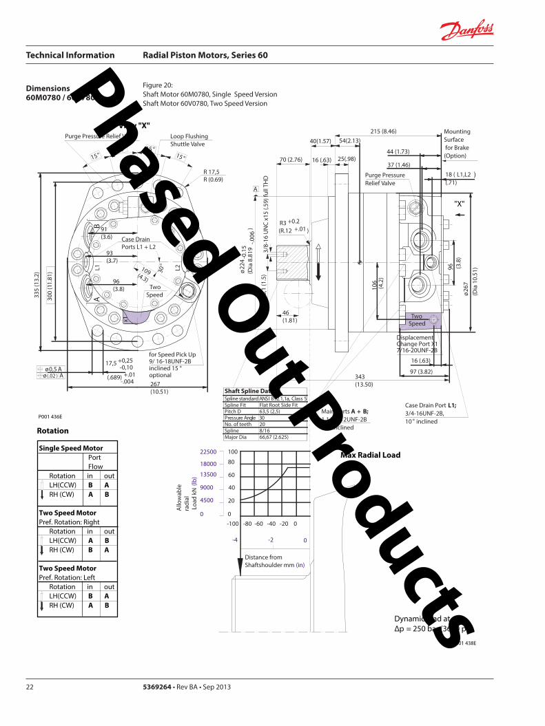
Technical Information Radial Piston Motors Series 60
5369264 bull Rev BA bull Sep 201322
Dimensions60M0780 60V780
Figure 20 Shaft Motor 60M0780 Single Speed VersionShaft Motor 60V0780 Two Speed Version
Single Speed MotorPortFlow
Rotation in outLH(CCW) B ARH (CW) A B
Two Speed MotorPref Rotation Right
Rotation in outLH(CCW) A BRH (CW) B A
Two Speed MotorPref Rotation Left
Rotation in outLH(CCW) B ARH (CW) A B
View X
for Speed Pick Up9 16-18UNF-2Binclined 15 degoptional
L2L1A
B
335
(13
2)
267(1051)
R 175R (069)
Purge Pressure Relief Valve
Case Drain Ports L1 + L2
Loop Flushing Shuttle Valve
x1
TwoSpeed
300
(11
81)
175 +025-010
(689) +01 -004
oslash05 Aoslash(02 ) A
30deg
15deg15deg
15deg15deg
96(38)
93(37)
91(36)
109(43)
X
P001 436E
Rotation
Max Radial Load
DisplacementChange Port X1716-20UNF-2B
Main Ports A + B1 116-12UNF-2B25deg inclined
Case Drain Port L134-16UNF-2B10deg inclined
44 (173)
18 ( L1L2 ) (71)
MountingSurface for Brake (Option)
Purge Pressure Relief Valve
oslash26
7(D
ia 1
051
)96 (38
)
16 (63)
106
(42
)
37 (146)
Two Speed
25(98)16 (63)
oslash22
4-0
15
(Dia
88
19-0
06)
343(1350)
215 (846)
40(157)
70 (276)
38-
16 U
NC
x15
(59)
full
THD
381
(15
)
46(181)
R3 +02(R12 +01 )
97 (382)
54(213)
A
-100 -80 -60 -40 -20 0
-4 -2
100
60
80
40
0
20
Allo
wab
lera
dial
Loa
d kN
(lb)
Distance from Shaftshoulder mm (in)
0
9000
13500
4500
18000
0
22500
P001 438E
Dynamic load at∆p = 250 bar (3600 psi)
Shaft Spline Data5 ssalC a1129B ISNA Spline standard
Spline Fit Pitch D
03 elgnA erusserPNo of teethSplineMajor Dia
Flat Root Side Fit635 (25)
208166667 (2625)
Phased Out Products
Technical Information Radial Piston Motors Series 60
369264 bull Rev BA bull Sep 2013 23
Dimensions60M1048 60V1048
Figure 21 Wheel Motor 60M1048 Single Speed VersionWheel Motor 60V0470 Two Speed Version
Single Speed MotorPortFlow
Rotation in outLH(CCW) B ARH (CW) A B
Two Speed MotorPref Rotation Right
Rotation in outLH(CCW) A BRH (CW) B A
Two Speed MotorPref Rotation Left
Rotation in outLH(CCW) B ARH (CW) A B
View X
P001 414E
X
P001 415E
295(1161)
x110
degdeg
L1A
B
R 20 R (079)
108(425)
108(425)
Purge Pressure Relief Valve Loop Flushing Shuttle Valve
L2
TwoSpeed37
5 (1
476
)
2020
20
Case Drain Ports L1 + L2
degdeg
335
(13
19)
225 +025-010
(89) +01 -004
30deg
for Speed Pick Up9 16-18UNF-2Binclined 15 degoptional
oslash075oslash(03 )
AA
118(465)
Rotation Radial Load Curve
20
40
60
80
100
0
4500
9000
13 500
18 000
22 500
Max
Rad
ial L
oad
kN (
lb)
Distance from Hub Mounting Face mm (in)
-200 -150 -100 -50 0 50 100 150 200 250
-79 -6 -4 -2 0 2 4 6 8 98
Dynamic load atDierentialPressure250 bar (3600 psi)
Studs 5x72 deg M22x15
Case Drain Ports L1 + L2 34-16UNF-2B
66( L2 ) (260)
565(222)
Main Ports A + B 075-Code 62Split Flange Boss per SAE J 51838-16UNC-2B 22 (088) min full thread depth
8 (31)
48 (189)
MountingSurface for Brake (Option)
16(63)
47(185)
Purge Pressure Relief Valve
112(441)
379(1492)
19 (75)
220(866)
8 (31)
oslash17
58
-02
(Dia
69
2 -0
1)
oslash22
5(D
ia 8
86)
280
(Dia
11
02)oslash
292
(Dia
115
0)
508
(20
0)
285
-02
(11
22-0
1)
96 (37
8)
DisplacementChange Port X1716-20UNF-2B
79 (31)
115
(45
3)
Two Speed
96 (378)
238(94)
81( L1 )(319)
24(9)
A
Phased Out Products
Technical Information Radial Piston Motors Series 60
5369264 bull Rev BA bull Sep 201324
Dimensions60M1048 60V1048
Figure 22 Flange Motor 60M1048 Single Speed VersionFlange Motor 60V1048 Two Speed Version
Single Speed MotorPortFlow
Rotation in outLH(CCW) B ARH (CW) A B
Two Speed MotorPref Rotation Right
Rotation in outLH(CCW) A BRH (CW) B A
Two Speed MotorPref Rotation Left
Rotation in outLH(CCW) B ARH (CW) A B
View X
X
295(1161)
x1
10deg
deg
L1A
B
R 20 R (079)
108(425)
108(425)
Purge Pressure Relief Valve Loop Flushing Shuttle Valve
L2
TwoSpeed37
5 (1
476
)
2020
20
Case Drain Ports L1 + L2
degdeg
335
(13
19)
225 +025-010
(89) +01 -004
30deg
for Speed Pick Up9 16-18UNF-2Binclined 15 degoptional
oslash075oslash(03 )
AA
118(465)
Dynamic loadat DierentialPressure250 bar (3600 psi)
Max
Rad
ial L
oad
kN (
lb)
0
20
40
60
4500
9000
13 500
0
Distance from Hub Mounting Face mm (in)
-4 -2 0 2 6-6-79 4 8 99
-200 -100 -50 0 50 100 150 200-150 250
Studs 6x60 deg M18x15
Case Drain Ports L1 + L2 34-16UNF-2B
66( L2 ) (26)
255(100)
Main Ports A + B 075-Code 62Split Flange Boss per SAE J 51838-16UNC-2B 22 (088) min full thread depth
8(31)
48 (189)
MountingSurface for Brake (Option)
15(59)
36(142)
Purge Pressure Relief Valve
112(441)
322(127)
19 (75)
1745(687)
6(24)
oslash16
08
-02
(Dia
63
3 -0
1)
oslash20
5 (D
ia 8
07)
250
(Dia
98
4)
oslash29
2(D
ia11
50)
508
(20
)
285
-02
(11
22-0
1)
96 (37
8)
DisplacementChange Port X1716-20UNF-2B
79 (311)11
5 (4
53)
Two Speed
96 (378)
238(94)
81( L1 )(319)
A
255 (10)
P001 415E
Rotation Radial Load Curve
P001 416E
Phased Out Products
Technical Information Radial Piston Motors Series 60
369264 bull Rev BA bull Sep 2013 25
Dimensions60M1048 60V1048
Figure 23 Shaft Motor 60M1048 Single Speed VersionShaft Motor 60M1048 Two Speed Version
Single Speed MotorPortFlow
Rotation in outLH(CCW) B ARH (CW) A B
Two Speed MotorPref Rotation Right
Rotation in outLH(CCW) A BRH (CW) B A
Two Speed MotorPref Rotation Left
Rotation in outLH(CCW) B ARH (CW) A B
View X
295(1161)
x110
degdeg
L1A
B
R 20 R (079)
108(425)
108(425)
Purge Pressure Relief Valve Loop Flushing Shuttle Valve
L2
TwoSpeed37
5 (1
476
)
2020
20
Case Drain Ports L1 + L2
degdeg
335
(13
19)
225 +025-010
(89) +01 -004
30deg
for Speed Pick Up9 16-18UNF-2Binclined 15 degoptional
oslash075oslash(03 )
AA
118(465)
P001 415E
Rotation
Max Radial Load
X
73 ( L1 )(287)
28(110)13 (51)
oslash28
0-0
15
(Dia
110
24-0
06)
372(146)
2325 (915)
50 (197)
70 (276)
38-
16U
NC
15 (
59) f
ull T
HD
381
(15
)
46(181)
123 (484)
R 3 +02(R12 +01 )
515 (203)
Main Ports A + B 075-Code 62Split Flange Boss per SAE J 51838-16UNC-2B22 (088) min full thread depth
Case Drain Ports L1+L234-16UNF-2B
40 (157)
MountingSurface for Brake (Option)
104(41)
238(94)
508
(20
0)
oslash29
2(D
ia11
5)96 (37
8)
DisplacementChange Port X1716-20UNF-2B
17(67)
115
(45
3)
Two Speed
58( L2 )(228)
PurgePressureRelief ValveA
-100 -80 -60 -40 -20 0
-4 -2
120
60
80
40
0
20
Allo
wab
lera
dial
Loa
d kN
(lb)
Distance from Shaftshoulder mm (in)
0
9000
13500
4500
18000
0
22500 10027000
P001 417E
Dynamic load at ∆p = 250 bar (3600 psi)
Shaft Spline Data5 ssalC a1129B ISNA Spline standard
Spline Fit Pitch Dia
03 elgnA erusserPNo of teethSplineMajor Dia
Flat Root Side Fit73025 (30)
23816762 (30)
Phased Out Products
Technical Information Radial Piston Motors Series 60
5369264 bull Rev BA bull Sep 201326
Dimensions60M1750 60V1750
Figure 24 Wheel Motor 60M1750 Single Speed VersionWheel Motor 60V1750 Two Speed Version
Single Speed MotorPortFlow
Rotation in outLH(CCW) B ARH (CW) A B
Two Speed MotorPref Rotation Right
Rotation in outLH(CCW) A BRH (CW) B A
Two Speed MotorPref Rotation Left
Rotation in outLH(CCW) B ARH (CW) A B
View X
X
Rotation Radial Load Curve
P001 430E
P001 429E
L2L1A
B
425
(16
73)
Purge Pressure Relief Valve
Case Drain Ports L1 + L2
Loop Flushing Shuttle Valve
x1
Two Speed
385
(15
16)
225 +025-010
(89) +01 -004
oslash075 Aoslash(03 ) A
30deg
for Speed Pick Up9 16-18UNF-2Binclined 15 degoptional
15deg15deg
15deg15deg
350(1378)
R 20 R (079)
124(488)
124(488)
138(543)
Dynamic load atDierentialPressure250 bar (3600 psi)
(in)Distance from Hub Mounting Face mm
-200 -150 -100 -50 0 50 100 150 200 250
-79 -6 -4 -2 0 2 4 6 8 98
Max
Rad
ial L
oad
kN (
lb)
20
40
140
160
60
80
100
120
180
0
4500
9000
13 500
27 000
36 000
18 000
22 500
31 500
40 500
0
Studs 10x36 deg M22x15
Case Drain Ports L1 + L2 78-14UNF-2B
69(272)
Main Ports A + B 100-Code 62Split Flange Boss per SAE J 518716-14UNC-2B 27 (106) min full thread depth
11(43)
66 (2598)
MountingSurface for Brake (Option)
16(63)
47(185)
Purge Pressure Relief Valve
132(520)
433(1705)
225 (886)
254(100)
8 (31)
oslash17
58
-02
(Dia
69
2 -0
1)
oslash22
5(D
ia 8
86)
280
(Dia
11
02)oslash
350
(Dia
137
8)
571
5(2
25)
oslash33
0-0
2(D
ia12
992
-008
)
115
(45
28)
DisplacementChange Port X1716-20UNF-2B
99 (390)
141
(55
5)
Two Speed
116 (4567)
2776(1093)
96( L1L2 )(378)
20(0787)
A
Phased Out Products
Technical Information Radial Piston Motors Series 60
369264 bull Rev BA bull Sep 2013 27
Dimensions60M1750 60V1750
Figure 25 Flange Motor 60M1750 Single Speed VersionFlange Motor 60V1750 Two Speed Version
Single Speed MotorPortFlow
Rotation in outLH(CCW) B ARH (CW) A B
Two Speed MotorPref Rotation Right
Rotation in outLH(CCW) A BRH (CW) B A
Two Speed MotorPref Rotation Left
Rotation in outLH(CCW) B ARH (CW) A B
View X
X
P001 430E
Rotation Radial Load Curve
P001 431E
L2L1A
B
425
(16
73)
Purge Pressure Relief Valve
Case Drain Ports L1 + L2
Loop Flushing Shuttle Valve
x1
Two Speed
385
(15
16)
225 +025-010
(89) +01 -004
oslash075 Aoslash(03 ) A
30deg
for Speed Pick Up9 16-18UNF-2Binclined 15 degoptional
15deg15deg
15deg15deg
350(1378)
R 20 R (079)
124(488)
124(488)
138(543)
0
Dynamic loadat DierentialPressure250 bar (3600 psi)
Distance from Hub Mounting Face mm (in)
-6 -4 -2 0 2 64 8 99-79
-200 -100 -50 0 50 100 150 200-150 250
Max
Rad
ial L
oad
kN (
lb)
0
20
40
60
4500
9000
13 500
8018 000
10022 500
12027 000
14031 500
16036 000
18040 500
Studs 10x36 deg M22x15
Case Drain Ports L1 + L2 78-14UNF-2B
32(126)
Main Ports A + B 100-Code 62Split Flange Boss per SAE J 518716-14UNC-2B 27 (106) min full thread depth
11(43)
66 (2598)
MountingSurface for Brake (Option)
16(63)
47(185)
Purge Pressure Relief Valve
132(520)
389(1531)
225 (886)
210(1827)
8 (31)
oslash17
58
-02
(Dia
69
2 -0
1)
oslash22
5(D
ia 8
86)
280
(Dia
11
02)oslash
350
(Dia
137
8)
571
5(2
25)
oslash33
0-0
2(D
ia 1
299
2-0
08)
115
(45
28)
DisplacementChange Port X1716-20UNF-2B
99 (390)
141
(55
5)
Two Speed
116 (4567)
2776(1093)
96( L1 L2 )(378)
29 (114)
A
Phased Out Products
Technical Information Radial Piston Motors Series 60
5369264 bull Rev BA bull Sep 201328
Dimensions60M1750 60V1750
Figure 26 Shaft Motor 60M1750 Single Speed VersionShaft Motor 60V1750 Two Speed Version
Single Speed MotorPortFlow
Rotation in outLH(CCW) B ARH (CW) A B
Two Speed MotorPref Rotation Right
Rotation in outLH(CCW) A BRH (CW) B A
Two Speed MotorPref Rotation Left
Rotation in outLH(CCW) B ARH (CW) A B
View X
L2L1A
B
425
(16
73)
Purge Pressure Relief Valve
Case Drain Ports L1 + L2
Loop Flushing Shuttle Valve
x1
Two Speed
385
(15
16)
225 +025-010
(89) +01 -004
oslash075 Aoslash(03 ) A
30deg
for Speed Pick Up9 16-18UNF-2Binclined 15 degoptional
15deg15deg
15deg15deg
350(1378)
R 20 R (079)
124(488)
124(488)
138(543)
P001 430E
Rotation
X
Max Radial Load
Displacementchange Port X1716-20UNF-2B
24(94)15 (59)
oslash31
5-0
15
(Dia
124
02-0
06)
440(173)
2835 (1116)
48 (189)
90 (354)
12-
13 U
NC
X22
(86)
full
THD
381
(15
)
63(248)
141 (555)
R4 +02(R16 +01 )
97 (382)
Main Ports A + B 100-Code 62Split Flange Boss per SAE J 518716-14UNC-2B27 (106) min full thread depth
Case Drain Ports L1+L278-20UNF-2B
20 (079) ( L1+L2 )
50 (197)
MountingSurface for Brake (Option)Purge Pressure
Relief Valve
121 (48)
278(109)
572
(22
5)
oslash33
0(D
ia12
99)11
5 (4
53)
17 (67)
141
(55
5)
Two Speed
9 (35)
oslash35
0(D
ia13
78)
A
-100 -80 -60 -40 -20 0
-4 -2
200
100
150
0
50
Allo
wab
lera
dial
Loa
d kN
(lb)
Distance from Shaftshoulder mm (in)
0
22500
11250
33750
0
45000
P001 432E
Dynamic load at ∆p = 250 bar (3600 psi)
Shaft Spline Data5 ssalC a1129B ISNA Spline standard
Spline Fit Pitch Dia
03 elgnA erusserPNo of teethSplineMajor Dia
Flat Root Side Fit889 (35)
288169207 (3625)
Phased Out Products
Technical Information Radial Piston Motors Series 60
369264 bull Rev BA bull Sep 2013 29
NotesPhased Out Products
Technical Information Radial Piston Motors Series 60
5369264 bull Rev BA bull Sep 201330
DimensionsBrakes
Figure 27 Radial Piston Motor with Brake (0ptional)
P001 418E
Table 6 Brake Dimensions
Series Dimension
A B C
60M0470 23 (090) 74 (290) oslash212 (Dia 835)
60M0780 42 (165) 100 (394) oslash245 (Dia 965)
60M1048 30 (118) 90 (354) oslash280 (Dia 1102)
60M1750 38 (147) 107 (421) oslash320 (Dia 1260)
B
CX7
MountingFace
Mechanical BrakeRelease 1 to be used with Mech Brake Release 2
Mechanical BrakeRelease 2to be used with Mech Brake Release 1
A
Hydraulic BrakeRelease X7916-18UNF-2B
Mechanical BrakeRelease 1 to be used with Mech Brake Release 2
Mechanical BrakeRelease 2to be used with Mech Brake Release 1
TwoSpeed
X
View X
Phased Out Products
Technical Information Radial Piston Motors Series 60
369264 bull Rev BA bull Sep 2013 31
DimensionsSpeed Sensor
Figure 28 Radial Piston Motor with Speed Sensor (0ptional)
Section A - A (11)Speed Sensor
Connecto IdNoStraightRight angle
Connector is not supplied with the motorPlease order separatly using above Id No
Table 7 Speed Sensor Connector
Electrical details see page12
P001 444E
A
A
30deg 15 deg
31m
ax (1
22)
Pin 1Pin 2
Pin 3
Pin 4
Key Way
Wrench-Flats
Connector Insert
View Y
Y
127
(50)
500724500725
Phased Out Products
Comatrolwwwcomatrolcom
Schwarzmuumlller-Inverterwwwschwarzmueller-invertercom
Turolla wwwturollaocgcom
Valmovawwwvalmovacom
Hydro-Gear wwwhydro-gearcom
Daikin-Sauer-Danfosswwwdaikin-sauer-danfosscom
Danfoss Power Solutions is a global manufacturer and supplier of high-quality hydraulic and electronic components We specialize in providing state-of-the-art technology and solutions that excel in the harsh operating conditions of the mobile off -highway market Building on our extensive applications expertise we work closely with our customers to ensure exceptional performance for a broad range of off -highway vehicles
We help OEMs around the world speed up system development reduce costs and bring vehicles to market faster Danfoss ndash Your Strongest Partner in Mobile Hydraulics
Go to wwwpowersolutionsdanfosscom for further product information
Wherever off -highway vehicles are at work so is Danfoss
We off er expert worldwide support for our customers ensuring the best possible solutions for outstanding performance And with an extensive network of Global Service Partners we also provide comprehensive global service for all of our components
Please contact the Danfoss Power Solution representative nearest you
Products we off er
Bent Axis Motors
Closed Circuit Axial Piston Pumps and Motors
Displays
Electrohydraulic Power Steering
Electrohydraulics
Hydraulic Power Steering
Integrated Systems
Joysticks and Control Handles
Microcontrollers and Software
Open Circuit Axial Piston Pumps
Orbital Motors
PLUS+1reg GUIDE
Proportional Valves
Sensors
Steering
Transit Mixer Drives
Local address
Danfoss can accept no responsibility for possible errors in catalogues brochures and other printed material Danfoss reserves the right to alter its products without notice This also applies to products already on order provided that such alterations can be made without subsequential changes being necessary in specifications already agreedAll trademarks in this material are property of the respective companies Danfoss and the Danfoss logotype are trademarks of Danfoss AS All rights reserved
Danfoss Power Solutions22F Block C Yishan RdShanghai 200233 ChinaPhone +86 21 3418 5200
Danfoss Power Solutions GmbH amp Co OHGKrokamp 35D-24539 Neumuumlnster GermanyPhone +49 4321 871 0
Danfoss Power Solutions ApSNordborgvej 81DK-6430 Nordborg DenmarkPhone +45 7488 2222
Danfoss Power Solutions US Company2800 East 13th StreetAmes IA 50010 USAPhone +1 515 239 6000
369264 bull Rev BA bull Sep 2013 wwwdanfosscom copy Danfoss AS 2013-09
Phased Out Products
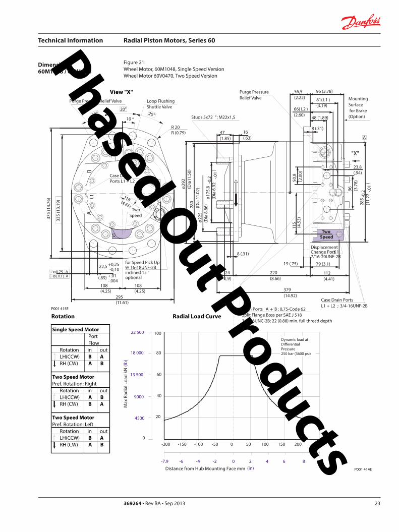
Technical Information Radial Piston Motors Series 60
369264 bull Rev BA bull Sep 2013 23
Dimensions60M1048 60V1048
Figure 21 Wheel Motor 60M1048 Single Speed VersionWheel Motor 60V0470 Two Speed Version
Single Speed MotorPortFlow
Rotation in outLH(CCW) B ARH (CW) A B
Two Speed MotorPref Rotation Right
Rotation in outLH(CCW) A BRH (CW) B A
Two Speed MotorPref Rotation Left
Rotation in outLH(CCW) B ARH (CW) A B
View X
P001 414E
X
P001 415E
295(1161)
x110
degdeg
L1A
B
R 20 R (079)
108(425)
108(425)
Purge Pressure Relief Valve Loop Flushing Shuttle Valve
L2
TwoSpeed37
5 (1
476
)
2020
20
Case Drain Ports L1 + L2
degdeg
335
(13
19)
225 +025-010
(89) +01 -004
30deg
for Speed Pick Up9 16-18UNF-2Binclined 15 degoptional
oslash075oslash(03 )
AA
118(465)
Rotation Radial Load Curve
20
40
60
80
100
0
4500
9000
13 500
18 000
22 500
Max
Rad
ial L
oad
kN (
lb)
Distance from Hub Mounting Face mm (in)
-200 -150 -100 -50 0 50 100 150 200 250
-79 -6 -4 -2 0 2 4 6 8 98
Dynamic load atDierentialPressure250 bar (3600 psi)
Studs 5x72 deg M22x15
Case Drain Ports L1 + L2 34-16UNF-2B
66( L2 ) (260)
565(222)
Main Ports A + B 075-Code 62Split Flange Boss per SAE J 51838-16UNC-2B 22 (088) min full thread depth
8 (31)
48 (189)
MountingSurface for Brake (Option)
16(63)
47(185)
Purge Pressure Relief Valve
112(441)
379(1492)
19 (75)
220(866)
8 (31)
oslash17
58
-02
(Dia
69
2 -0
1)
oslash22
5(D
ia 8
86)
280
(Dia
11
02)oslash
292
(Dia
115
0)
508
(20
0)
285
-02
(11
22-0
1)
96 (37
8)
DisplacementChange Port X1716-20UNF-2B
79 (31)
115
(45
3)
Two Speed
96 (378)
238(94)
81( L1 )(319)
24(9)
A
Phased Out Products
Technical Information Radial Piston Motors Series 60
5369264 bull Rev BA bull Sep 201324
Dimensions60M1048 60V1048
Figure 22 Flange Motor 60M1048 Single Speed VersionFlange Motor 60V1048 Two Speed Version
Single Speed MotorPortFlow
Rotation in outLH(CCW) B ARH (CW) A B
Two Speed MotorPref Rotation Right
Rotation in outLH(CCW) A BRH (CW) B A
Two Speed MotorPref Rotation Left
Rotation in outLH(CCW) B ARH (CW) A B
View X
X
295(1161)
x1
10deg
deg
L1A
B
R 20 R (079)
108(425)
108(425)
Purge Pressure Relief Valve Loop Flushing Shuttle Valve
L2
TwoSpeed37
5 (1
476
)
2020
20
Case Drain Ports L1 + L2
degdeg
335
(13
19)
225 +025-010
(89) +01 -004
30deg
for Speed Pick Up9 16-18UNF-2Binclined 15 degoptional
oslash075oslash(03 )
AA
118(465)
Dynamic loadat DierentialPressure250 bar (3600 psi)
Max
Rad
ial L
oad
kN (
lb)
0
20
40
60
4500
9000
13 500
0
Distance from Hub Mounting Face mm (in)
-4 -2 0 2 6-6-79 4 8 99
-200 -100 -50 0 50 100 150 200-150 250
Studs 6x60 deg M18x15
Case Drain Ports L1 + L2 34-16UNF-2B
66( L2 ) (26)
255(100)
Main Ports A + B 075-Code 62Split Flange Boss per SAE J 51838-16UNC-2B 22 (088) min full thread depth
8(31)
48 (189)
MountingSurface for Brake (Option)
15(59)
36(142)
Purge Pressure Relief Valve
112(441)
322(127)
19 (75)
1745(687)
6(24)
oslash16
08
-02
(Dia
63
3 -0
1)
oslash20
5 (D
ia 8
07)
250
(Dia
98
4)
oslash29
2(D
ia11
50)
508
(20
)
285
-02
(11
22-0
1)
96 (37
8)
DisplacementChange Port X1716-20UNF-2B
79 (311)11
5 (4
53)
Two Speed
96 (378)
238(94)
81( L1 )(319)
A
255 (10)
P001 415E
Rotation Radial Load Curve
P001 416E
Phased Out Products
Technical Information Radial Piston Motors Series 60
369264 bull Rev BA bull Sep 2013 25
Dimensions60M1048 60V1048
Figure 23 Shaft Motor 60M1048 Single Speed VersionShaft Motor 60M1048 Two Speed Version
Single Speed MotorPortFlow
Rotation in outLH(CCW) B ARH (CW) A B
Two Speed MotorPref Rotation Right
Rotation in outLH(CCW) A BRH (CW) B A
Two Speed MotorPref Rotation Left
Rotation in outLH(CCW) B ARH (CW) A B
View X
295(1161)
x110
degdeg
L1A
B
R 20 R (079)
108(425)
108(425)
Purge Pressure Relief Valve Loop Flushing Shuttle Valve
L2
TwoSpeed37
5 (1
476
)
2020
20
Case Drain Ports L1 + L2
degdeg
335
(13
19)
225 +025-010
(89) +01 -004
30deg
for Speed Pick Up9 16-18UNF-2Binclined 15 degoptional
oslash075oslash(03 )
AA
118(465)
P001 415E
Rotation
Max Radial Load
X
73 ( L1 )(287)
28(110)13 (51)
oslash28
0-0
15
(Dia
110
24-0
06)
372(146)
2325 (915)
50 (197)
70 (276)
38-
16U
NC
15 (
59) f
ull T
HD
381
(15
)
46(181)
123 (484)
R 3 +02(R12 +01 )
515 (203)
Main Ports A + B 075-Code 62Split Flange Boss per SAE J 51838-16UNC-2B22 (088) min full thread depth
Case Drain Ports L1+L234-16UNF-2B
40 (157)
MountingSurface for Brake (Option)
104(41)
238(94)
508
(20
0)
oslash29
2(D
ia11
5)96 (37
8)
DisplacementChange Port X1716-20UNF-2B
17(67)
115
(45
3)
Two Speed
58( L2 )(228)
PurgePressureRelief ValveA
-100 -80 -60 -40 -20 0
-4 -2
120
60
80
40
0
20
Allo
wab
lera
dial
Loa
d kN
(lb)
Distance from Shaftshoulder mm (in)
0
9000
13500
4500
18000
0
22500 10027000
P001 417E
Dynamic load at ∆p = 250 bar (3600 psi)
Shaft Spline Data5 ssalC a1129B ISNA Spline standard
Spline Fit Pitch Dia
03 elgnA erusserPNo of teethSplineMajor Dia
Flat Root Side Fit73025 (30)
23816762 (30)
Phased Out Products
Technical Information Radial Piston Motors Series 60
5369264 bull Rev BA bull Sep 201326
Dimensions60M1750 60V1750
Figure 24 Wheel Motor 60M1750 Single Speed VersionWheel Motor 60V1750 Two Speed Version
Single Speed MotorPortFlow
Rotation in outLH(CCW) B ARH (CW) A B
Two Speed MotorPref Rotation Right
Rotation in outLH(CCW) A BRH (CW) B A
Two Speed MotorPref Rotation Left
Rotation in outLH(CCW) B ARH (CW) A B
View X
X
Rotation Radial Load Curve
P001 430E
P001 429E
L2L1A
B
425
(16
73)
Purge Pressure Relief Valve
Case Drain Ports L1 + L2
Loop Flushing Shuttle Valve
x1
Two Speed
385
(15
16)
225 +025-010
(89) +01 -004
oslash075 Aoslash(03 ) A
30deg
for Speed Pick Up9 16-18UNF-2Binclined 15 degoptional
15deg15deg
15deg15deg
350(1378)
R 20 R (079)
124(488)
124(488)
138(543)
Dynamic load atDierentialPressure250 bar (3600 psi)
(in)Distance from Hub Mounting Face mm
-200 -150 -100 -50 0 50 100 150 200 250
-79 -6 -4 -2 0 2 4 6 8 98
Max
Rad
ial L
oad
kN (
lb)
20
40
140
160
60
80
100
120
180
0
4500
9000
13 500
27 000
36 000
18 000
22 500
31 500
40 500
0
Studs 10x36 deg M22x15
Case Drain Ports L1 + L2 78-14UNF-2B
69(272)
Main Ports A + B 100-Code 62Split Flange Boss per SAE J 518716-14UNC-2B 27 (106) min full thread depth
11(43)
66 (2598)
MountingSurface for Brake (Option)
16(63)
47(185)
Purge Pressure Relief Valve
132(520)
433(1705)
225 (886)
254(100)
8 (31)
oslash17
58
-02
(Dia
69
2 -0
1)
oslash22
5(D
ia 8
86)
280
(Dia
11
02)oslash
350
(Dia
137
8)
571
5(2
25)
oslash33
0-0
2(D
ia12
992
-008
)
115
(45
28)
DisplacementChange Port X1716-20UNF-2B
99 (390)
141
(55
5)
Two Speed
116 (4567)
2776(1093)
96( L1L2 )(378)
20(0787)
A
Phased Out Products
Technical Information Radial Piston Motors Series 60
369264 bull Rev BA bull Sep 2013 27
Dimensions60M1750 60V1750
Figure 25 Flange Motor 60M1750 Single Speed VersionFlange Motor 60V1750 Two Speed Version
Single Speed MotorPortFlow
Rotation in outLH(CCW) B ARH (CW) A B
Two Speed MotorPref Rotation Right
Rotation in outLH(CCW) A BRH (CW) B A
Two Speed MotorPref Rotation Left
Rotation in outLH(CCW) B ARH (CW) A B
View X
X
P001 430E
Rotation Radial Load Curve
P001 431E
L2L1A
B
425
(16
73)
Purge Pressure Relief Valve
Case Drain Ports L1 + L2
Loop Flushing Shuttle Valve
x1
Two Speed
385
(15
16)
225 +025-010
(89) +01 -004
oslash075 Aoslash(03 ) A
30deg
for Speed Pick Up9 16-18UNF-2Binclined 15 degoptional
15deg15deg
15deg15deg
350(1378)
R 20 R (079)
124(488)
124(488)
138(543)
0
Dynamic loadat DierentialPressure250 bar (3600 psi)
Distance from Hub Mounting Face mm (in)
-6 -4 -2 0 2 64 8 99-79
-200 -100 -50 0 50 100 150 200-150 250
Max
Rad
ial L
oad
kN (
lb)
0
20
40
60
4500
9000
13 500
8018 000
10022 500
12027 000
14031 500
16036 000
18040 500
Studs 10x36 deg M22x15
Case Drain Ports L1 + L2 78-14UNF-2B
32(126)
Main Ports A + B 100-Code 62Split Flange Boss per SAE J 518716-14UNC-2B 27 (106) min full thread depth
11(43)
66 (2598)
MountingSurface for Brake (Option)
16(63)
47(185)
Purge Pressure Relief Valve
132(520)
389(1531)
225 (886)
210(1827)
8 (31)
oslash17
58
-02
(Dia
69
2 -0
1)
oslash22
5(D
ia 8
86)
280
(Dia
11
02)oslash
350
(Dia
137
8)
571
5(2
25)
oslash33
0-0
2(D
ia 1
299
2-0
08)
115
(45
28)
DisplacementChange Port X1716-20UNF-2B
99 (390)
141
(55
5)
Two Speed
116 (4567)
2776(1093)
96( L1 L2 )(378)
29 (114)
A
Phased Out Products
Technical Information Radial Piston Motors Series 60
5369264 bull Rev BA bull Sep 201328
Dimensions60M1750 60V1750
Figure 26 Shaft Motor 60M1750 Single Speed VersionShaft Motor 60V1750 Two Speed Version
Single Speed MotorPortFlow
Rotation in outLH(CCW) B ARH (CW) A B
Two Speed MotorPref Rotation Right
Rotation in outLH(CCW) A BRH (CW) B A
Two Speed MotorPref Rotation Left
Rotation in outLH(CCW) B ARH (CW) A B
View X
L2L1A
B
425
(16
73)
Purge Pressure Relief Valve
Case Drain Ports L1 + L2
Loop Flushing Shuttle Valve
x1
Two Speed
385
(15
16)
225 +025-010
(89) +01 -004
oslash075 Aoslash(03 ) A
30deg
for Speed Pick Up9 16-18UNF-2Binclined 15 degoptional
15deg15deg
15deg15deg
350(1378)
R 20 R (079)
124(488)
124(488)
138(543)
P001 430E
Rotation
X
Max Radial Load
Displacementchange Port X1716-20UNF-2B
24(94)15 (59)
oslash31
5-0
15
(Dia
124
02-0
06)
440(173)
2835 (1116)
48 (189)
90 (354)
12-
13 U
NC
X22
(86)
full
THD
381
(15
)
63(248)
141 (555)
R4 +02(R16 +01 )
97 (382)
Main Ports A + B 100-Code 62Split Flange Boss per SAE J 518716-14UNC-2B27 (106) min full thread depth
Case Drain Ports L1+L278-20UNF-2B
20 (079) ( L1+L2 )
50 (197)
MountingSurface for Brake (Option)Purge Pressure
Relief Valve
121 (48)
278(109)
572
(22
5)
oslash33
0(D
ia12
99)11
5 (4
53)
17 (67)
141
(55
5)
Two Speed
9 (35)
oslash35
0(D
ia13
78)
A
-100 -80 -60 -40 -20 0
-4 -2
200
100
150
0
50
Allo
wab
lera
dial
Loa
d kN
(lb)
Distance from Shaftshoulder mm (in)
0
22500
11250
33750
0
45000
P001 432E
Dynamic load at ∆p = 250 bar (3600 psi)
Shaft Spline Data5 ssalC a1129B ISNA Spline standard
Spline Fit Pitch Dia
03 elgnA erusserPNo of teethSplineMajor Dia
Flat Root Side Fit889 (35)
288169207 (3625)
Phased Out Products
Technical Information Radial Piston Motors Series 60
369264 bull Rev BA bull Sep 2013 29
NotesPhased Out Products
Technical Information Radial Piston Motors Series 60
5369264 bull Rev BA bull Sep 201330
DimensionsBrakes
Figure 27 Radial Piston Motor with Brake (0ptional)
P001 418E
Table 6 Brake Dimensions
Series Dimension
A B C
60M0470 23 (090) 74 (290) oslash212 (Dia 835)
60M0780 42 (165) 100 (394) oslash245 (Dia 965)
60M1048 30 (118) 90 (354) oslash280 (Dia 1102)
60M1750 38 (147) 107 (421) oslash320 (Dia 1260)
B
CX7
MountingFace
Mechanical BrakeRelease 1 to be used with Mech Brake Release 2
Mechanical BrakeRelease 2to be used with Mech Brake Release 1
A
Hydraulic BrakeRelease X7916-18UNF-2B
Mechanical BrakeRelease 1 to be used with Mech Brake Release 2
Mechanical BrakeRelease 2to be used with Mech Brake Release 1
TwoSpeed
X
View X
Phased Out Products
Technical Information Radial Piston Motors Series 60
369264 bull Rev BA bull Sep 2013 31
DimensionsSpeed Sensor
Figure 28 Radial Piston Motor with Speed Sensor (0ptional)
Section A - A (11)Speed Sensor
Connecto IdNoStraightRight angle
Connector is not supplied with the motorPlease order separatly using above Id No
Table 7 Speed Sensor Connector
Electrical details see page12
P001 444E
A
A
30deg 15 deg
31m
ax (1
22)
Pin 1Pin 2
Pin 3
Pin 4
Key Way
Wrench-Flats
Connector Insert
View Y
Y
127
(50)
500724500725
Phased Out Products
Comatrolwwwcomatrolcom
Schwarzmuumlller-Inverterwwwschwarzmueller-invertercom
Turolla wwwturollaocgcom
Valmovawwwvalmovacom
Hydro-Gear wwwhydro-gearcom
Daikin-Sauer-Danfosswwwdaikin-sauer-danfosscom
Danfoss Power Solutions is a global manufacturer and supplier of high-quality hydraulic and electronic components We specialize in providing state-of-the-art technology and solutions that excel in the harsh operating conditions of the mobile off -highway market Building on our extensive applications expertise we work closely with our customers to ensure exceptional performance for a broad range of off -highway vehicles
We help OEMs around the world speed up system development reduce costs and bring vehicles to market faster Danfoss ndash Your Strongest Partner in Mobile Hydraulics
Go to wwwpowersolutionsdanfosscom for further product information
Wherever off -highway vehicles are at work so is Danfoss
We off er expert worldwide support for our customers ensuring the best possible solutions for outstanding performance And with an extensive network of Global Service Partners we also provide comprehensive global service for all of our components
Please contact the Danfoss Power Solution representative nearest you
Products we off er
Bent Axis Motors
Closed Circuit Axial Piston Pumps and Motors
Displays
Electrohydraulic Power Steering
Electrohydraulics
Hydraulic Power Steering
Integrated Systems
Joysticks and Control Handles
Microcontrollers and Software
Open Circuit Axial Piston Pumps
Orbital Motors
PLUS+1reg GUIDE
Proportional Valves
Sensors
Steering
Transit Mixer Drives
Local address
Danfoss can accept no responsibility for possible errors in catalogues brochures and other printed material Danfoss reserves the right to alter its products without notice This also applies to products already on order provided that such alterations can be made without subsequential changes being necessary in specifications already agreedAll trademarks in this material are property of the respective companies Danfoss and the Danfoss logotype are trademarks of Danfoss AS All rights reserved
Danfoss Power Solutions22F Block C Yishan RdShanghai 200233 ChinaPhone +86 21 3418 5200
Danfoss Power Solutions GmbH amp Co OHGKrokamp 35D-24539 Neumuumlnster GermanyPhone +49 4321 871 0
Danfoss Power Solutions ApSNordborgvej 81DK-6430 Nordborg DenmarkPhone +45 7488 2222
Danfoss Power Solutions US Company2800 East 13th StreetAmes IA 50010 USAPhone +1 515 239 6000
369264 bull Rev BA bull Sep 2013 wwwdanfosscom copy Danfoss AS 2013-09
Phased Out Products
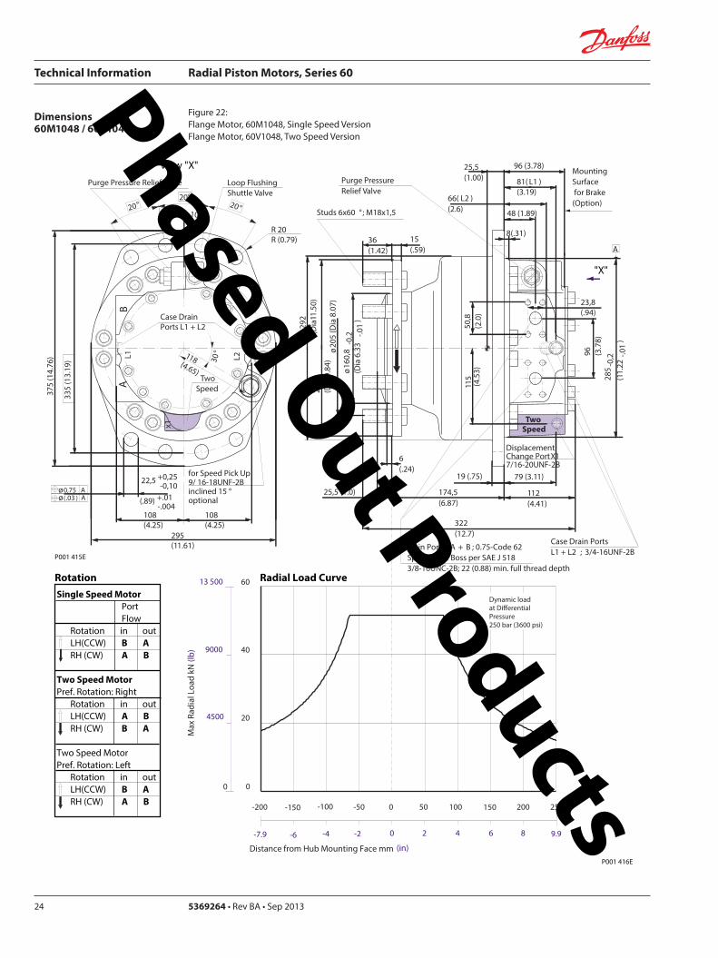
Technical Information Radial Piston Motors Series 60
5369264 bull Rev BA bull Sep 201324
Dimensions60M1048 60V1048
Figure 22 Flange Motor 60M1048 Single Speed VersionFlange Motor 60V1048 Two Speed Version
Single Speed MotorPortFlow
Rotation in outLH(CCW) B ARH (CW) A B
Two Speed MotorPref Rotation Right
Rotation in outLH(CCW) A BRH (CW) B A
Two Speed MotorPref Rotation Left
Rotation in outLH(CCW) B ARH (CW) A B
View X
X
295(1161)
x1
10deg
deg
L1A
B
R 20 R (079)
108(425)
108(425)
Purge Pressure Relief Valve Loop Flushing Shuttle Valve
L2
TwoSpeed37
5 (1
476
)
2020
20
Case Drain Ports L1 + L2
degdeg
335
(13
19)
225 +025-010
(89) +01 -004
30deg
for Speed Pick Up9 16-18UNF-2Binclined 15 degoptional
oslash075oslash(03 )
AA
118(465)
Dynamic loadat DierentialPressure250 bar (3600 psi)
Max
Rad
ial L
oad
kN (
lb)
0
20
40
60
4500
9000
13 500
0
Distance from Hub Mounting Face mm (in)
-4 -2 0 2 6-6-79 4 8 99
-200 -100 -50 0 50 100 150 200-150 250
Studs 6x60 deg M18x15
Case Drain Ports L1 + L2 34-16UNF-2B
66( L2 ) (26)
255(100)
Main Ports A + B 075-Code 62Split Flange Boss per SAE J 51838-16UNC-2B 22 (088) min full thread depth
8(31)
48 (189)
MountingSurface for Brake (Option)
15(59)
36(142)
Purge Pressure Relief Valve
112(441)
322(127)
19 (75)
1745(687)
6(24)
oslash16
08
-02
(Dia
63
3 -0
1)
oslash20
5 (D
ia 8
07)
250
(Dia
98
4)
oslash29
2(D
ia11
50)
508
(20
)
285
-02
(11
22-0
1)
96 (37
8)
DisplacementChange Port X1716-20UNF-2B
79 (311)11
5 (4
53)
Two Speed
96 (378)
238(94)
81( L1 )(319)
A
255 (10)
P001 415E
Rotation Radial Load Curve
P001 416E
Phased Out Products
Technical Information Radial Piston Motors Series 60
369264 bull Rev BA bull Sep 2013 25
Dimensions60M1048 60V1048
Figure 23 Shaft Motor 60M1048 Single Speed VersionShaft Motor 60M1048 Two Speed Version
Single Speed MotorPortFlow
Rotation in outLH(CCW) B ARH (CW) A B
Two Speed MotorPref Rotation Right
Rotation in outLH(CCW) A BRH (CW) B A
Two Speed MotorPref Rotation Left
Rotation in outLH(CCW) B ARH (CW) A B
View X
295(1161)
x110
degdeg
L1A
B
R 20 R (079)
108(425)
108(425)
Purge Pressure Relief Valve Loop Flushing Shuttle Valve
L2
TwoSpeed37
5 (1
476
)
2020
20
Case Drain Ports L1 + L2
degdeg
335
(13
19)
225 +025-010
(89) +01 -004
30deg
for Speed Pick Up9 16-18UNF-2Binclined 15 degoptional
oslash075oslash(03 )
AA
118(465)
P001 415E
Rotation
Max Radial Load
X
73 ( L1 )(287)
28(110)13 (51)
oslash28
0-0
15
(Dia
110
24-0
06)
372(146)
2325 (915)
50 (197)
70 (276)
38-
16U
NC
15 (
59) f
ull T
HD
381
(15
)
46(181)
123 (484)
R 3 +02(R12 +01 )
515 (203)
Main Ports A + B 075-Code 62Split Flange Boss per SAE J 51838-16UNC-2B22 (088) min full thread depth
Case Drain Ports L1+L234-16UNF-2B
40 (157)
MountingSurface for Brake (Option)
104(41)
238(94)
508
(20
0)
oslash29
2(D
ia11
5)96 (37
8)
DisplacementChange Port X1716-20UNF-2B
17(67)
115
(45
3)
Two Speed
58( L2 )(228)
PurgePressureRelief ValveA
-100 -80 -60 -40 -20 0
-4 -2
120
60
80
40
0
20
Allo
wab
lera
dial
Loa
d kN
(lb)
Distance from Shaftshoulder mm (in)
0
9000
13500
4500
18000
0
22500 10027000
P001 417E
Dynamic load at ∆p = 250 bar (3600 psi)
Shaft Spline Data5 ssalC a1129B ISNA Spline standard
Spline Fit Pitch Dia
03 elgnA erusserPNo of teethSplineMajor Dia
Flat Root Side Fit73025 (30)
23816762 (30)
Phased Out Products
Technical Information Radial Piston Motors Series 60
5369264 bull Rev BA bull Sep 201326
Dimensions60M1750 60V1750
Figure 24 Wheel Motor 60M1750 Single Speed VersionWheel Motor 60V1750 Two Speed Version
Single Speed MotorPortFlow
Rotation in outLH(CCW) B ARH (CW) A B
Two Speed MotorPref Rotation Right
Rotation in outLH(CCW) A BRH (CW) B A
Two Speed MotorPref Rotation Left
Rotation in outLH(CCW) B ARH (CW) A B
View X
X
Rotation Radial Load Curve
P001 430E
P001 429E
L2L1A
B
425
(16
73)
Purge Pressure Relief Valve
Case Drain Ports L1 + L2
Loop Flushing Shuttle Valve
x1
Two Speed
385
(15
16)
225 +025-010
(89) +01 -004
oslash075 Aoslash(03 ) A
30deg
for Speed Pick Up9 16-18UNF-2Binclined 15 degoptional
15deg15deg
15deg15deg
350(1378)
R 20 R (079)
124(488)
124(488)
138(543)
Dynamic load atDierentialPressure250 bar (3600 psi)
(in)Distance from Hub Mounting Face mm
-200 -150 -100 -50 0 50 100 150 200 250
-79 -6 -4 -2 0 2 4 6 8 98
Max
Rad
ial L
oad
kN (
lb)
20
40
140
160
60
80
100
120
180
0
4500
9000
13 500
27 000
36 000
18 000
22 500
31 500
40 500
0
Studs 10x36 deg M22x15
Case Drain Ports L1 + L2 78-14UNF-2B
69(272)
Main Ports A + B 100-Code 62Split Flange Boss per SAE J 518716-14UNC-2B 27 (106) min full thread depth
11(43)
66 (2598)
MountingSurface for Brake (Option)
16(63)
47(185)
Purge Pressure Relief Valve
132(520)
433(1705)
225 (886)
254(100)
8 (31)
oslash17
58
-02
(Dia
69
2 -0
1)
oslash22
5(D
ia 8
86)
280
(Dia
11
02)oslash
350
(Dia
137
8)
571
5(2
25)
oslash33
0-0
2(D
ia12
992
-008
)
115
(45
28)
DisplacementChange Port X1716-20UNF-2B
99 (390)
141
(55
5)
Two Speed
116 (4567)
2776(1093)
96( L1L2 )(378)
20(0787)
A
Phased Out Products
Technical Information Radial Piston Motors Series 60
369264 bull Rev BA bull Sep 2013 27
Dimensions60M1750 60V1750
Figure 25 Flange Motor 60M1750 Single Speed VersionFlange Motor 60V1750 Two Speed Version
Single Speed MotorPortFlow
Rotation in outLH(CCW) B ARH (CW) A B
Two Speed MotorPref Rotation Right
Rotation in outLH(CCW) A BRH (CW) B A
Two Speed MotorPref Rotation Left
Rotation in outLH(CCW) B ARH (CW) A B
View X
X
P001 430E
Rotation Radial Load Curve
P001 431E
L2L1A
B
425
(16
73)
Purge Pressure Relief Valve
Case Drain Ports L1 + L2
Loop Flushing Shuttle Valve
x1
Two Speed
385
(15
16)
225 +025-010
(89) +01 -004
oslash075 Aoslash(03 ) A
30deg
for Speed Pick Up9 16-18UNF-2Binclined 15 degoptional
15deg15deg
15deg15deg
350(1378)
R 20 R (079)
124(488)
124(488)
138(543)
0
Dynamic loadat DierentialPressure250 bar (3600 psi)
Distance from Hub Mounting Face mm (in)
-6 -4 -2 0 2 64 8 99-79
-200 -100 -50 0 50 100 150 200-150 250
Max
Rad
ial L
oad
kN (
lb)
0
20
40
60
4500
9000
13 500
8018 000
10022 500
12027 000
14031 500
16036 000
18040 500
Studs 10x36 deg M22x15
Case Drain Ports L1 + L2 78-14UNF-2B
32(126)
Main Ports A + B 100-Code 62Split Flange Boss per SAE J 518716-14UNC-2B 27 (106) min full thread depth
11(43)
66 (2598)
MountingSurface for Brake (Option)
16(63)
47(185)
Purge Pressure Relief Valve
132(520)
389(1531)
225 (886)
210(1827)
8 (31)
oslash17
58
-02
(Dia
69
2 -0
1)
oslash22
5(D
ia 8
86)
280
(Dia
11
02)oslash
350
(Dia
137
8)
571
5(2
25)
oslash33
0-0
2(D
ia 1
299
2-0
08)
115
(45
28)
DisplacementChange Port X1716-20UNF-2B
99 (390)
141
(55
5)
Two Speed
116 (4567)
2776(1093)
96( L1 L2 )(378)
29 (114)
A
Phased Out Products
Technical Information Radial Piston Motors Series 60
5369264 bull Rev BA bull Sep 201328
Dimensions60M1750 60V1750
Figure 26 Shaft Motor 60M1750 Single Speed VersionShaft Motor 60V1750 Two Speed Version
Single Speed MotorPortFlow
Rotation in outLH(CCW) B ARH (CW) A B
Two Speed MotorPref Rotation Right
Rotation in outLH(CCW) A BRH (CW) B A
Two Speed MotorPref Rotation Left
Rotation in outLH(CCW) B ARH (CW) A B
View X
L2L1A
B
425
(16
73)
Purge Pressure Relief Valve
Case Drain Ports L1 + L2
Loop Flushing Shuttle Valve
x1
Two Speed
385
(15
16)
225 +025-010
(89) +01 -004
oslash075 Aoslash(03 ) A
30deg
for Speed Pick Up9 16-18UNF-2Binclined 15 degoptional
15deg15deg
15deg15deg
350(1378)
R 20 R (079)
124(488)
124(488)
138(543)
P001 430E
Rotation
X
Max Radial Load
Displacementchange Port X1716-20UNF-2B
24(94)15 (59)
oslash31
5-0
15
(Dia
124
02-0
06)
440(173)
2835 (1116)
48 (189)
90 (354)
12-
13 U
NC
X22
(86)
full
THD
381
(15
)
63(248)
141 (555)
R4 +02(R16 +01 )
97 (382)
Main Ports A + B 100-Code 62Split Flange Boss per SAE J 518716-14UNC-2B27 (106) min full thread depth
Case Drain Ports L1+L278-20UNF-2B
20 (079) ( L1+L2 )
50 (197)
MountingSurface for Brake (Option)Purge Pressure
Relief Valve
121 (48)
278(109)
572
(22
5)
oslash33
0(D
ia12
99)11
5 (4
53)
17 (67)
141
(55
5)
Two Speed
9 (35)
oslash35
0(D
ia13
78)
A
-100 -80 -60 -40 -20 0
-4 -2
200
100
150
0
50
Allo
wab
lera
dial
Loa
d kN
(lb)
Distance from Shaftshoulder mm (in)
0
22500
11250
33750
0
45000
P001 432E
Dynamic load at ∆p = 250 bar (3600 psi)
Shaft Spline Data5 ssalC a1129B ISNA Spline standard
Spline Fit Pitch Dia
03 elgnA erusserPNo of teethSplineMajor Dia
Flat Root Side Fit889 (35)
288169207 (3625)
Phased Out Products
Technical Information Radial Piston Motors Series 60
369264 bull Rev BA bull Sep 2013 29
NotesPhased Out Products
Technical Information Radial Piston Motors Series 60
5369264 bull Rev BA bull Sep 201330
DimensionsBrakes
Figure 27 Radial Piston Motor with Brake (0ptional)
P001 418E
Table 6 Brake Dimensions
Series Dimension
A B C
60M0470 23 (090) 74 (290) oslash212 (Dia 835)
60M0780 42 (165) 100 (394) oslash245 (Dia 965)
60M1048 30 (118) 90 (354) oslash280 (Dia 1102)
60M1750 38 (147) 107 (421) oslash320 (Dia 1260)
B
CX7
MountingFace
Mechanical BrakeRelease 1 to be used with Mech Brake Release 2
Mechanical BrakeRelease 2to be used with Mech Brake Release 1
A
Hydraulic BrakeRelease X7916-18UNF-2B
Mechanical BrakeRelease 1 to be used with Mech Brake Release 2
Mechanical BrakeRelease 2to be used with Mech Brake Release 1
TwoSpeed
X
View X
Phased Out Products
Technical Information Radial Piston Motors Series 60
369264 bull Rev BA bull Sep 2013 31
DimensionsSpeed Sensor
Figure 28 Radial Piston Motor with Speed Sensor (0ptional)
Section A - A (11)Speed Sensor
Connecto IdNoStraightRight angle
Connector is not supplied with the motorPlease order separatly using above Id No
Table 7 Speed Sensor Connector
Electrical details see page12
P001 444E
A
A
30deg 15 deg
31m
ax (1
22)
Pin 1Pin 2
Pin 3
Pin 4
Key Way
Wrench-Flats
Connector Insert
View Y
Y
127
(50)
500724500725
Phased Out Products
Comatrolwwwcomatrolcom
Schwarzmuumlller-Inverterwwwschwarzmueller-invertercom
Turolla wwwturollaocgcom
Valmovawwwvalmovacom
Hydro-Gear wwwhydro-gearcom
Daikin-Sauer-Danfosswwwdaikin-sauer-danfosscom
Danfoss Power Solutions is a global manufacturer and supplier of high-quality hydraulic and electronic components We specialize in providing state-of-the-art technology and solutions that excel in the harsh operating conditions of the mobile off -highway market Building on our extensive applications expertise we work closely with our customers to ensure exceptional performance for a broad range of off -highway vehicles
We help OEMs around the world speed up system development reduce costs and bring vehicles to market faster Danfoss ndash Your Strongest Partner in Mobile Hydraulics
Go to wwwpowersolutionsdanfosscom for further product information
Wherever off -highway vehicles are at work so is Danfoss
We off er expert worldwide support for our customers ensuring the best possible solutions for outstanding performance And with an extensive network of Global Service Partners we also provide comprehensive global service for all of our components
Please contact the Danfoss Power Solution representative nearest you
Products we off er
Bent Axis Motors
Closed Circuit Axial Piston Pumps and Motors
Displays
Electrohydraulic Power Steering
Electrohydraulics
Hydraulic Power Steering
Integrated Systems
Joysticks and Control Handles
Microcontrollers and Software
Open Circuit Axial Piston Pumps
Orbital Motors
PLUS+1reg GUIDE
Proportional Valves
Sensors
Steering
Transit Mixer Drives
Local address
Danfoss can accept no responsibility for possible errors in catalogues brochures and other printed material Danfoss reserves the right to alter its products without notice This also applies to products already on order provided that such alterations can be made without subsequential changes being necessary in specifications already agreedAll trademarks in this material are property of the respective companies Danfoss and the Danfoss logotype are trademarks of Danfoss AS All rights reserved
Danfoss Power Solutions22F Block C Yishan RdShanghai 200233 ChinaPhone +86 21 3418 5200
Danfoss Power Solutions GmbH amp Co OHGKrokamp 35D-24539 Neumuumlnster GermanyPhone +49 4321 871 0
Danfoss Power Solutions ApSNordborgvej 81DK-6430 Nordborg DenmarkPhone +45 7488 2222
Danfoss Power Solutions US Company2800 East 13th StreetAmes IA 50010 USAPhone +1 515 239 6000
369264 bull Rev BA bull Sep 2013 wwwdanfosscom copy Danfoss AS 2013-09
Phased Out Products
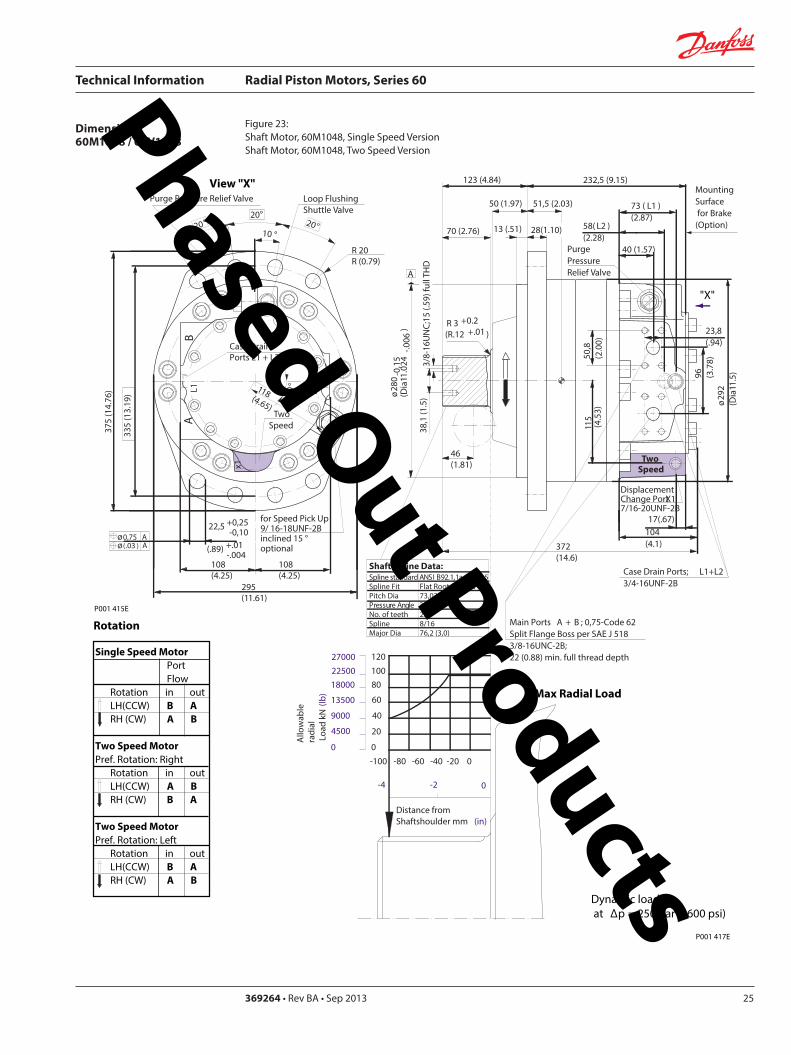
Technical Information Radial Piston Motors Series 60
369264 bull Rev BA bull Sep 2013 25
Dimensions60M1048 60V1048
Figure 23 Shaft Motor 60M1048 Single Speed VersionShaft Motor 60M1048 Two Speed Version
Single Speed MotorPortFlow
Rotation in outLH(CCW) B ARH (CW) A B
Two Speed MotorPref Rotation Right
Rotation in outLH(CCW) A BRH (CW) B A
Two Speed MotorPref Rotation Left
Rotation in outLH(CCW) B ARH (CW) A B
View X
295(1161)
x110
degdeg
L1A
B
R 20 R (079)
108(425)
108(425)
Purge Pressure Relief Valve Loop Flushing Shuttle Valve
L2
TwoSpeed37
5 (1
476
)
2020
20
Case Drain Ports L1 + L2
degdeg
335
(13
19)
225 +025-010
(89) +01 -004
30deg
for Speed Pick Up9 16-18UNF-2Binclined 15 degoptional
oslash075oslash(03 )
AA
118(465)
P001 415E
Rotation
Max Radial Load
X
73 ( L1 )(287)
28(110)13 (51)
oslash28
0-0
15
(Dia
110
24-0
06)
372(146)
2325 (915)
50 (197)
70 (276)
38-
16U
NC
15 (
59) f
ull T
HD
381
(15
)
46(181)
123 (484)
R 3 +02(R12 +01 )
515 (203)
Main Ports A + B 075-Code 62Split Flange Boss per SAE J 51838-16UNC-2B22 (088) min full thread depth
Case Drain Ports L1+L234-16UNF-2B
40 (157)
MountingSurface for Brake (Option)
104(41)
238(94)
508
(20
0)
oslash29
2(D
ia11
5)96 (37
8)
DisplacementChange Port X1716-20UNF-2B
17(67)
115
(45
3)
Two Speed
58( L2 )(228)
PurgePressureRelief ValveA
-100 -80 -60 -40 -20 0
-4 -2
120
60
80
40
0
20
Allo
wab
lera
dial
Loa
d kN
(lb)
Distance from Shaftshoulder mm (in)
0
9000
13500
4500
18000
0
22500 10027000
P001 417E
Dynamic load at ∆p = 250 bar (3600 psi)
Shaft Spline Data5 ssalC a1129B ISNA Spline standard
Spline Fit Pitch Dia
03 elgnA erusserPNo of teethSplineMajor Dia
Flat Root Side Fit73025 (30)
23816762 (30)
Phased Out Products
Technical Information Radial Piston Motors Series 60
5369264 bull Rev BA bull Sep 201326
Dimensions60M1750 60V1750
Figure 24 Wheel Motor 60M1750 Single Speed VersionWheel Motor 60V1750 Two Speed Version
Single Speed MotorPortFlow
Rotation in outLH(CCW) B ARH (CW) A B
Two Speed MotorPref Rotation Right
Rotation in outLH(CCW) A BRH (CW) B A
Two Speed MotorPref Rotation Left
Rotation in outLH(CCW) B ARH (CW) A B
View X
X
Rotation Radial Load Curve
P001 430E
P001 429E
L2L1A
B
425
(16
73)
Purge Pressure Relief Valve
Case Drain Ports L1 + L2
Loop Flushing Shuttle Valve
x1
Two Speed
385
(15
16)
225 +025-010
(89) +01 -004
oslash075 Aoslash(03 ) A
30deg
for Speed Pick Up9 16-18UNF-2Binclined 15 degoptional
15deg15deg
15deg15deg
350(1378)
R 20 R (079)
124(488)
124(488)
138(543)
Dynamic load atDierentialPressure250 bar (3600 psi)
(in)Distance from Hub Mounting Face mm
-200 -150 -100 -50 0 50 100 150 200 250
-79 -6 -4 -2 0 2 4 6 8 98
Max
Rad
ial L
oad
kN (
lb)
20
40
140
160
60
80
100
120
180
0
4500
9000
13 500
27 000
36 000
18 000
22 500
31 500
40 500
0
Studs 10x36 deg M22x15
Case Drain Ports L1 + L2 78-14UNF-2B
69(272)
Main Ports A + B 100-Code 62Split Flange Boss per SAE J 518716-14UNC-2B 27 (106) min full thread depth
11(43)
66 (2598)
MountingSurface for Brake (Option)
16(63)
47(185)
Purge Pressure Relief Valve
132(520)
433(1705)
225 (886)
254(100)
8 (31)
oslash17
58
-02
(Dia
69
2 -0
1)
oslash22
5(D
ia 8
86)
280
(Dia
11
02)oslash
350
(Dia
137
8)
571
5(2
25)
oslash33
0-0
2(D
ia12
992
-008
)
115
(45
28)
DisplacementChange Port X1716-20UNF-2B
99 (390)
141
(55
5)
Two Speed
116 (4567)
2776(1093)
96( L1L2 )(378)
20(0787)
A
Phased Out Products
Technical Information Radial Piston Motors Series 60
369264 bull Rev BA bull Sep 2013 27
Dimensions60M1750 60V1750
Figure 25 Flange Motor 60M1750 Single Speed VersionFlange Motor 60V1750 Two Speed Version
Single Speed MotorPortFlow
Rotation in outLH(CCW) B ARH (CW) A B
Two Speed MotorPref Rotation Right
Rotation in outLH(CCW) A BRH (CW) B A
Two Speed MotorPref Rotation Left
Rotation in outLH(CCW) B ARH (CW) A B
View X
X
P001 430E
Rotation Radial Load Curve
P001 431E
L2L1A
B
425
(16
73)
Purge Pressure Relief Valve
Case Drain Ports L1 + L2
Loop Flushing Shuttle Valve
x1
Two Speed
385
(15
16)
225 +025-010
(89) +01 -004
oslash075 Aoslash(03 ) A
30deg
for Speed Pick Up9 16-18UNF-2Binclined 15 degoptional
15deg15deg
15deg15deg
350(1378)
R 20 R (079)
124(488)
124(488)
138(543)
0
Dynamic loadat DierentialPressure250 bar (3600 psi)
Distance from Hub Mounting Face mm (in)
-6 -4 -2 0 2 64 8 99-79
-200 -100 -50 0 50 100 150 200-150 250
Max
Rad
ial L
oad
kN (
lb)
0
20
40
60
4500
9000
13 500
8018 000
10022 500
12027 000
14031 500
16036 000
18040 500
Studs 10x36 deg M22x15
Case Drain Ports L1 + L2 78-14UNF-2B
32(126)
Main Ports A + B 100-Code 62Split Flange Boss per SAE J 518716-14UNC-2B 27 (106) min full thread depth
11(43)
66 (2598)
MountingSurface for Brake (Option)
16(63)
47(185)
Purge Pressure Relief Valve
132(520)
389(1531)
225 (886)
210(1827)
8 (31)
oslash17
58
-02
(Dia
69
2 -0
1)
oslash22
5(D
ia 8
86)
280
(Dia
11
02)oslash
350
(Dia
137
8)
571
5(2
25)
oslash33
0-0
2(D
ia 1
299
2-0
08)
115
(45
28)
DisplacementChange Port X1716-20UNF-2B
99 (390)
141
(55
5)
Two Speed
116 (4567)
2776(1093)
96( L1 L2 )(378)
29 (114)
A
Phased Out Products
Technical Information Radial Piston Motors Series 60
5369264 bull Rev BA bull Sep 201328
Dimensions60M1750 60V1750
Figure 26 Shaft Motor 60M1750 Single Speed VersionShaft Motor 60V1750 Two Speed Version
Single Speed MotorPortFlow
Rotation in outLH(CCW) B ARH (CW) A B
Two Speed MotorPref Rotation Right
Rotation in outLH(CCW) A BRH (CW) B A
Two Speed MotorPref Rotation Left
Rotation in outLH(CCW) B ARH (CW) A B
View X
L2L1A
B
425
(16
73)
Purge Pressure Relief Valve
Case Drain Ports L1 + L2
Loop Flushing Shuttle Valve
x1
Two Speed
385
(15
16)
225 +025-010
(89) +01 -004
oslash075 Aoslash(03 ) A
30deg
for Speed Pick Up9 16-18UNF-2Binclined 15 degoptional
15deg15deg
15deg15deg
350(1378)
R 20 R (079)
124(488)
124(488)
138(543)
P001 430E
Rotation
X
Max Radial Load
Displacementchange Port X1716-20UNF-2B
24(94)15 (59)
oslash31
5-0
15
(Dia
124
02-0
06)
440(173)
2835 (1116)
48 (189)
90 (354)
12-
13 U
NC
X22
(86)
full
THD
381
(15
)
63(248)
141 (555)
R4 +02(R16 +01 )
97 (382)
Main Ports A + B 100-Code 62Split Flange Boss per SAE J 518716-14UNC-2B27 (106) min full thread depth
Case Drain Ports L1+L278-20UNF-2B
20 (079) ( L1+L2 )
50 (197)
MountingSurface for Brake (Option)Purge Pressure
Relief Valve
121 (48)
278(109)
572
(22
5)
oslash33
0(D
ia12
99)11
5 (4
53)
17 (67)
141
(55
5)
Two Speed
9 (35)
oslash35
0(D
ia13
78)
A
-100 -80 -60 -40 -20 0
-4 -2
200
100
150
0
50
Allo
wab
lera
dial
Loa
d kN
(lb)
Distance from Shaftshoulder mm (in)
0
22500
11250
33750
0
45000
P001 432E
Dynamic load at ∆p = 250 bar (3600 psi)
Shaft Spline Data5 ssalC a1129B ISNA Spline standard
Spline Fit Pitch Dia
03 elgnA erusserPNo of teethSplineMajor Dia
Flat Root Side Fit889 (35)
288169207 (3625)
Phased Out Products
Technical Information Radial Piston Motors Series 60
369264 bull Rev BA bull Sep 2013 29
NotesPhased Out Products
Technical Information Radial Piston Motors Series 60
5369264 bull Rev BA bull Sep 201330
DimensionsBrakes
Figure 27 Radial Piston Motor with Brake (0ptional)
P001 418E
Table 6 Brake Dimensions
Series Dimension
A B C
60M0470 23 (090) 74 (290) oslash212 (Dia 835)
60M0780 42 (165) 100 (394) oslash245 (Dia 965)
60M1048 30 (118) 90 (354) oslash280 (Dia 1102)
60M1750 38 (147) 107 (421) oslash320 (Dia 1260)
B
CX7
MountingFace
Mechanical BrakeRelease 1 to be used with Mech Brake Release 2
Mechanical BrakeRelease 2to be used with Mech Brake Release 1
A
Hydraulic BrakeRelease X7916-18UNF-2B
Mechanical BrakeRelease 1 to be used with Mech Brake Release 2
Mechanical BrakeRelease 2to be used with Mech Brake Release 1
TwoSpeed
X
View X
Phased Out Products
Technical Information Radial Piston Motors Series 60
369264 bull Rev BA bull Sep 2013 31
DimensionsSpeed Sensor
Figure 28 Radial Piston Motor with Speed Sensor (0ptional)
Section A - A (11)Speed Sensor
Connecto IdNoStraightRight angle
Connector is not supplied with the motorPlease order separatly using above Id No
Table 7 Speed Sensor Connector
Electrical details see page12
P001 444E
A
A
30deg 15 deg
31m
ax (1
22)
Pin 1Pin 2
Pin 3
Pin 4
Key Way
Wrench-Flats
Connector Insert
View Y
Y
127
(50)
500724500725
Phased Out Products
Comatrolwwwcomatrolcom
Schwarzmuumlller-Inverterwwwschwarzmueller-invertercom
Turolla wwwturollaocgcom
Valmovawwwvalmovacom
Hydro-Gear wwwhydro-gearcom
Daikin-Sauer-Danfosswwwdaikin-sauer-danfosscom
Danfoss Power Solutions is a global manufacturer and supplier of high-quality hydraulic and electronic components We specialize in providing state-of-the-art technology and solutions that excel in the harsh operating conditions of the mobile off -highway market Building on our extensive applications expertise we work closely with our customers to ensure exceptional performance for a broad range of off -highway vehicles
We help OEMs around the world speed up system development reduce costs and bring vehicles to market faster Danfoss ndash Your Strongest Partner in Mobile Hydraulics
Go to wwwpowersolutionsdanfosscom for further product information
Wherever off -highway vehicles are at work so is Danfoss
We off er expert worldwide support for our customers ensuring the best possible solutions for outstanding performance And with an extensive network of Global Service Partners we also provide comprehensive global service for all of our components
Please contact the Danfoss Power Solution representative nearest you
Products we off er
Bent Axis Motors
Closed Circuit Axial Piston Pumps and Motors
Displays
Electrohydraulic Power Steering
Electrohydraulics
Hydraulic Power Steering
Integrated Systems
Joysticks and Control Handles
Microcontrollers and Software
Open Circuit Axial Piston Pumps
Orbital Motors
PLUS+1reg GUIDE
Proportional Valves
Sensors
Steering
Transit Mixer Drives
Local address
Danfoss can accept no responsibility for possible errors in catalogues brochures and other printed material Danfoss reserves the right to alter its products without notice This also applies to products already on order provided that such alterations can be made without subsequential changes being necessary in specifications already agreedAll trademarks in this material are property of the respective companies Danfoss and the Danfoss logotype are trademarks of Danfoss AS All rights reserved
Danfoss Power Solutions22F Block C Yishan RdShanghai 200233 ChinaPhone +86 21 3418 5200
Danfoss Power Solutions GmbH amp Co OHGKrokamp 35D-24539 Neumuumlnster GermanyPhone +49 4321 871 0
Danfoss Power Solutions ApSNordborgvej 81DK-6430 Nordborg DenmarkPhone +45 7488 2222
Danfoss Power Solutions US Company2800 East 13th StreetAmes IA 50010 USAPhone +1 515 239 6000
369264 bull Rev BA bull Sep 2013 wwwdanfosscom copy Danfoss AS 2013-09
Phased Out Products
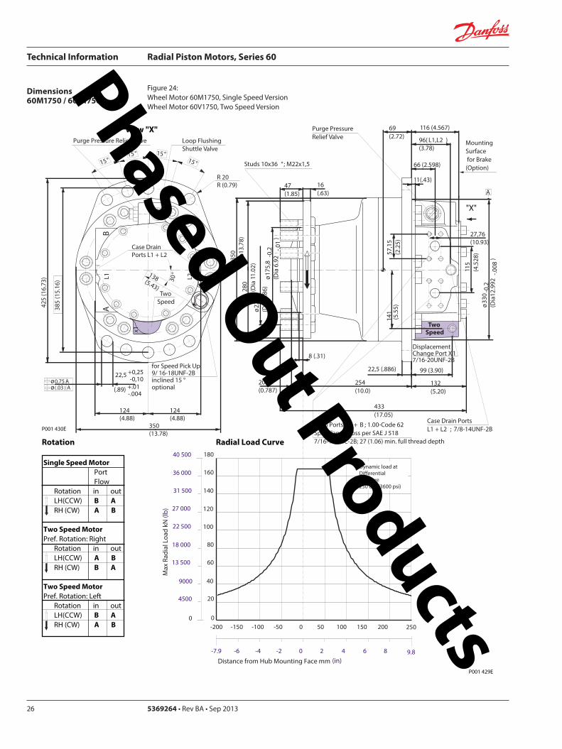
Technical Information Radial Piston Motors Series 60
5369264 bull Rev BA bull Sep 201326
Dimensions60M1750 60V1750
Figure 24 Wheel Motor 60M1750 Single Speed VersionWheel Motor 60V1750 Two Speed Version
Single Speed MotorPortFlow
Rotation in outLH(CCW) B ARH (CW) A B
Two Speed MotorPref Rotation Right
Rotation in outLH(CCW) A BRH (CW) B A
Two Speed MotorPref Rotation Left
Rotation in outLH(CCW) B ARH (CW) A B
View X
X
Rotation Radial Load Curve
P001 430E
P001 429E
L2L1A
B
425
(16
73)
Purge Pressure Relief Valve
Case Drain Ports L1 + L2
Loop Flushing Shuttle Valve
x1
Two Speed
385
(15
16)
225 +025-010
(89) +01 -004
oslash075 Aoslash(03 ) A
30deg
for Speed Pick Up9 16-18UNF-2Binclined 15 degoptional
15deg15deg
15deg15deg
350(1378)
R 20 R (079)
124(488)
124(488)
138(543)
Dynamic load atDierentialPressure250 bar (3600 psi)
(in)Distance from Hub Mounting Face mm
-200 -150 -100 -50 0 50 100 150 200 250
-79 -6 -4 -2 0 2 4 6 8 98
Max
Rad
ial L
oad
kN (
lb)
20
40
140
160
60
80
100
120
180
0
4500
9000
13 500
27 000
36 000
18 000
22 500
31 500
40 500
0
Studs 10x36 deg M22x15
Case Drain Ports L1 + L2 78-14UNF-2B
69(272)
Main Ports A + B 100-Code 62Split Flange Boss per SAE J 518716-14UNC-2B 27 (106) min full thread depth
11(43)
66 (2598)
MountingSurface for Brake (Option)
16(63)
47(185)
Purge Pressure Relief Valve
132(520)
433(1705)
225 (886)
254(100)
8 (31)
oslash17
58
-02
(Dia
69
2 -0
1)
oslash22
5(D
ia 8
86)
280
(Dia
11
02)oslash
350
(Dia
137
8)
571
5(2
25)
oslash33
0-0
2(D
ia12
992
-008
)
115
(45
28)
DisplacementChange Port X1716-20UNF-2B
99 (390)
141
(55
5)
Two Speed
116 (4567)
2776(1093)
96( L1L2 )(378)
20(0787)
A
Phased Out Products
Technical Information Radial Piston Motors Series 60
369264 bull Rev BA bull Sep 2013 27
Dimensions60M1750 60V1750
Figure 25 Flange Motor 60M1750 Single Speed VersionFlange Motor 60V1750 Two Speed Version
Single Speed MotorPortFlow
Rotation in outLH(CCW) B ARH (CW) A B
Two Speed MotorPref Rotation Right
Rotation in outLH(CCW) A BRH (CW) B A
Two Speed MotorPref Rotation Left
Rotation in outLH(CCW) B ARH (CW) A B
View X
X
P001 430E
Rotation Radial Load Curve
P001 431E
L2L1A
B
425
(16
73)
Purge Pressure Relief Valve
Case Drain Ports L1 + L2
Loop Flushing Shuttle Valve
x1
Two Speed
385
(15
16)
225 +025-010
(89) +01 -004
oslash075 Aoslash(03 ) A
30deg
for Speed Pick Up9 16-18UNF-2Binclined 15 degoptional
15deg15deg
15deg15deg
350(1378)
R 20 R (079)
124(488)
124(488)
138(543)
0
Dynamic loadat DierentialPressure250 bar (3600 psi)
Distance from Hub Mounting Face mm (in)
-6 -4 -2 0 2 64 8 99-79
-200 -100 -50 0 50 100 150 200-150 250
Max
Rad
ial L
oad
kN (
lb)
0
20
40
60
4500
9000
13 500
8018 000
10022 500
12027 000
14031 500
16036 000
18040 500
Studs 10x36 deg M22x15
Case Drain Ports L1 + L2 78-14UNF-2B
32(126)
Main Ports A + B 100-Code 62Split Flange Boss per SAE J 518716-14UNC-2B 27 (106) min full thread depth
11(43)
66 (2598)
MountingSurface for Brake (Option)
16(63)
47(185)
Purge Pressure Relief Valve
132(520)
389(1531)
225 (886)
210(1827)
8 (31)
oslash17
58
-02
(Dia
69
2 -0
1)
oslash22
5(D
ia 8
86)
280
(Dia
11
02)oslash
350
(Dia
137
8)
571
5(2
25)
oslash33
0-0
2(D
ia 1
299
2-0
08)
115
(45
28)
DisplacementChange Port X1716-20UNF-2B
99 (390)
141
(55
5)
Two Speed
116 (4567)
2776(1093)
96( L1 L2 )(378)
29 (114)
A
Phased Out Products
Technical Information Radial Piston Motors Series 60
5369264 bull Rev BA bull Sep 201328
Dimensions60M1750 60V1750
Figure 26 Shaft Motor 60M1750 Single Speed VersionShaft Motor 60V1750 Two Speed Version
Single Speed MotorPortFlow
Rotation in outLH(CCW) B ARH (CW) A B
Two Speed MotorPref Rotation Right
Rotation in outLH(CCW) A BRH (CW) B A
Two Speed MotorPref Rotation Left
Rotation in outLH(CCW) B ARH (CW) A B
View X
L2L1A
B
425
(16
73)
Purge Pressure Relief Valve
Case Drain Ports L1 + L2
Loop Flushing Shuttle Valve
x1
Two Speed
385
(15
16)
225 +025-010
(89) +01 -004
oslash075 Aoslash(03 ) A
30deg
for Speed Pick Up9 16-18UNF-2Binclined 15 degoptional
15deg15deg
15deg15deg
350(1378)
R 20 R (079)
124(488)
124(488)
138(543)
P001 430E
Rotation
X
Max Radial Load
Displacementchange Port X1716-20UNF-2B
24(94)15 (59)
oslash31
5-0
15
(Dia
124
02-0
06)
440(173)
2835 (1116)
48 (189)
90 (354)
12-
13 U
NC
X22
(86)
full
THD
381
(15
)
63(248)
141 (555)
R4 +02(R16 +01 )
97 (382)
Main Ports A + B 100-Code 62Split Flange Boss per SAE J 518716-14UNC-2B27 (106) min full thread depth
Case Drain Ports L1+L278-20UNF-2B
20 (079) ( L1+L2 )
50 (197)
MountingSurface for Brake (Option)Purge Pressure
Relief Valve
121 (48)
278(109)
572
(22
5)
oslash33
0(D
ia12
99)11
5 (4
53)
17 (67)
141
(55
5)
Two Speed
9 (35)
oslash35
0(D
ia13
78)
A
-100 -80 -60 -40 -20 0
-4 -2
200
100
150
0
50
Allo
wab
lera
dial
Loa
d kN
(lb)
Distance from Shaftshoulder mm (in)
0
22500
11250
33750
0
45000
P001 432E
Dynamic load at ∆p = 250 bar (3600 psi)
Shaft Spline Data5 ssalC a1129B ISNA Spline standard
Spline Fit Pitch Dia
03 elgnA erusserPNo of teethSplineMajor Dia
Flat Root Side Fit889 (35)
288169207 (3625)
Phased Out Products
Technical Information Radial Piston Motors Series 60
369264 bull Rev BA bull Sep 2013 29
NotesPhased Out Products
Technical Information Radial Piston Motors Series 60
5369264 bull Rev BA bull Sep 201330
DimensionsBrakes
Figure 27 Radial Piston Motor with Brake (0ptional)
P001 418E
Table 6 Brake Dimensions
Series Dimension
A B C
60M0470 23 (090) 74 (290) oslash212 (Dia 835)
60M0780 42 (165) 100 (394) oslash245 (Dia 965)
60M1048 30 (118) 90 (354) oslash280 (Dia 1102)
60M1750 38 (147) 107 (421) oslash320 (Dia 1260)
B
CX7
MountingFace
Mechanical BrakeRelease 1 to be used with Mech Brake Release 2
Mechanical BrakeRelease 2to be used with Mech Brake Release 1
A
Hydraulic BrakeRelease X7916-18UNF-2B
Mechanical BrakeRelease 1 to be used with Mech Brake Release 2
Mechanical BrakeRelease 2to be used with Mech Brake Release 1
TwoSpeed
X
View X
Phased Out Products
Technical Information Radial Piston Motors Series 60
369264 bull Rev BA bull Sep 2013 31
DimensionsSpeed Sensor
Figure 28 Radial Piston Motor with Speed Sensor (0ptional)
Section A - A (11)Speed Sensor
Connecto IdNoStraightRight angle
Connector is not supplied with the motorPlease order separatly using above Id No
Table 7 Speed Sensor Connector
Electrical details see page12
P001 444E
A
A
30deg 15 deg
31m
ax (1
22)
Pin 1Pin 2
Pin 3
Pin 4
Key Way
Wrench-Flats
Connector Insert
View Y
Y
127
(50)
500724500725
Phased Out Products
Comatrolwwwcomatrolcom
Schwarzmuumlller-Inverterwwwschwarzmueller-invertercom
Turolla wwwturollaocgcom
Valmovawwwvalmovacom
Hydro-Gear wwwhydro-gearcom
Daikin-Sauer-Danfosswwwdaikin-sauer-danfosscom
Danfoss Power Solutions is a global manufacturer and supplier of high-quality hydraulic and electronic components We specialize in providing state-of-the-art technology and solutions that excel in the harsh operating conditions of the mobile off -highway market Building on our extensive applications expertise we work closely with our customers to ensure exceptional performance for a broad range of off -highway vehicles
We help OEMs around the world speed up system development reduce costs and bring vehicles to market faster Danfoss ndash Your Strongest Partner in Mobile Hydraulics
Go to wwwpowersolutionsdanfosscom for further product information
Wherever off -highway vehicles are at work so is Danfoss
We off er expert worldwide support for our customers ensuring the best possible solutions for outstanding performance And with an extensive network of Global Service Partners we also provide comprehensive global service for all of our components
Please contact the Danfoss Power Solution representative nearest you
Products we off er
Bent Axis Motors
Closed Circuit Axial Piston Pumps and Motors
Displays
Electrohydraulic Power Steering
Electrohydraulics
Hydraulic Power Steering
Integrated Systems
Joysticks and Control Handles
Microcontrollers and Software
Open Circuit Axial Piston Pumps
Orbital Motors
PLUS+1reg GUIDE
Proportional Valves
Sensors
Steering
Transit Mixer Drives
Local address
Danfoss can accept no responsibility for possible errors in catalogues brochures and other printed material Danfoss reserves the right to alter its products without notice This also applies to products already on order provided that such alterations can be made without subsequential changes being necessary in specifications already agreedAll trademarks in this material are property of the respective companies Danfoss and the Danfoss logotype are trademarks of Danfoss AS All rights reserved
Danfoss Power Solutions22F Block C Yishan RdShanghai 200233 ChinaPhone +86 21 3418 5200
Danfoss Power Solutions GmbH amp Co OHGKrokamp 35D-24539 Neumuumlnster GermanyPhone +49 4321 871 0
Danfoss Power Solutions ApSNordborgvej 81DK-6430 Nordborg DenmarkPhone +45 7488 2222
Danfoss Power Solutions US Company2800 East 13th StreetAmes IA 50010 USAPhone +1 515 239 6000
369264 bull Rev BA bull Sep 2013 wwwdanfosscom copy Danfoss AS 2013-09
Phased Out Products
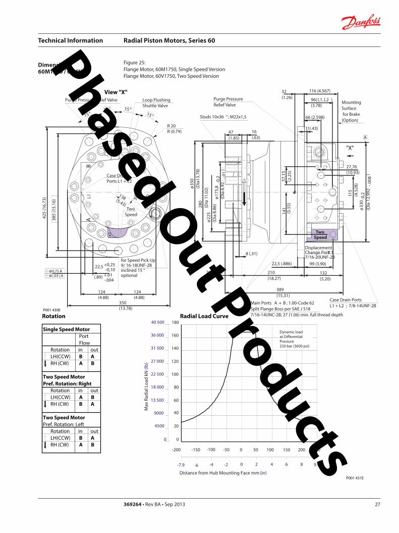
Technical Information Radial Piston Motors Series 60
369264 bull Rev BA bull Sep 2013 27
Dimensions60M1750 60V1750
Figure 25 Flange Motor 60M1750 Single Speed VersionFlange Motor 60V1750 Two Speed Version
Single Speed MotorPortFlow
Rotation in outLH(CCW) B ARH (CW) A B
Two Speed MotorPref Rotation Right
Rotation in outLH(CCW) A BRH (CW) B A
Two Speed MotorPref Rotation Left
Rotation in outLH(CCW) B ARH (CW) A B
View X
X
P001 430E
Rotation Radial Load Curve
P001 431E
L2L1A
B
425
(16
73)
Purge Pressure Relief Valve
Case Drain Ports L1 + L2
Loop Flushing Shuttle Valve
x1
Two Speed
385
(15
16)
225 +025-010
(89) +01 -004
oslash075 Aoslash(03 ) A
30deg
for Speed Pick Up9 16-18UNF-2Binclined 15 degoptional
15deg15deg
15deg15deg
350(1378)
R 20 R (079)
124(488)
124(488)
138(543)
0
Dynamic loadat DierentialPressure250 bar (3600 psi)
Distance from Hub Mounting Face mm (in)
-6 -4 -2 0 2 64 8 99-79
-200 -100 -50 0 50 100 150 200-150 250
Max
Rad
ial L
oad
kN (
lb)
0
20
40
60
4500
9000
13 500
8018 000
10022 500
12027 000
14031 500
16036 000
18040 500
Studs 10x36 deg M22x15
Case Drain Ports L1 + L2 78-14UNF-2B
32(126)
Main Ports A + B 100-Code 62Split Flange Boss per SAE J 518716-14UNC-2B 27 (106) min full thread depth
11(43)
66 (2598)
MountingSurface for Brake (Option)
16(63)
47(185)
Purge Pressure Relief Valve
132(520)
389(1531)
225 (886)
210(1827)
8 (31)
oslash17
58
-02
(Dia
69
2 -0
1)
oslash22
5(D
ia 8
86)
280
(Dia
11
02)oslash
350
(Dia
137
8)
571
5(2
25)
oslash33
0-0
2(D
ia 1
299
2-0
08)
115
(45
28)
DisplacementChange Port X1716-20UNF-2B
99 (390)
141
(55
5)
Two Speed
116 (4567)
2776(1093)
96( L1 L2 )(378)
29 (114)
A
Phased Out Products
Technical Information Radial Piston Motors Series 60
5369264 bull Rev BA bull Sep 201328
Dimensions60M1750 60V1750
Figure 26 Shaft Motor 60M1750 Single Speed VersionShaft Motor 60V1750 Two Speed Version
Single Speed MotorPortFlow
Rotation in outLH(CCW) B ARH (CW) A B
Two Speed MotorPref Rotation Right
Rotation in outLH(CCW) A BRH (CW) B A
Two Speed MotorPref Rotation Left
Rotation in outLH(CCW) B ARH (CW) A B
View X
L2L1A
B
425
(16
73)
Purge Pressure Relief Valve
Case Drain Ports L1 + L2
Loop Flushing Shuttle Valve
x1
Two Speed
385
(15
16)
225 +025-010
(89) +01 -004
oslash075 Aoslash(03 ) A
30deg
for Speed Pick Up9 16-18UNF-2Binclined 15 degoptional
15deg15deg
15deg15deg
350(1378)
R 20 R (079)
124(488)
124(488)
138(543)
P001 430E
Rotation
X
Max Radial Load
Displacementchange Port X1716-20UNF-2B
24(94)15 (59)
oslash31
5-0
15
(Dia
124
02-0
06)
440(173)
2835 (1116)
48 (189)
90 (354)
12-
13 U
NC
X22
(86)
full
THD
381
(15
)
63(248)
141 (555)
R4 +02(R16 +01 )
97 (382)
Main Ports A + B 100-Code 62Split Flange Boss per SAE J 518716-14UNC-2B27 (106) min full thread depth
Case Drain Ports L1+L278-20UNF-2B
20 (079) ( L1+L2 )
50 (197)
MountingSurface for Brake (Option)Purge Pressure
Relief Valve
121 (48)
278(109)
572
(22
5)
oslash33
0(D
ia12
99)11
5 (4
53)
17 (67)
141
(55
5)
Two Speed
9 (35)
oslash35
0(D
ia13
78)
A
-100 -80 -60 -40 -20 0
-4 -2
200
100
150
0
50
Allo
wab
lera
dial
Loa
d kN
(lb)
Distance from Shaftshoulder mm (in)
0
22500
11250
33750
0
45000
P001 432E
Dynamic load at ∆p = 250 bar (3600 psi)
Shaft Spline Data5 ssalC a1129B ISNA Spline standard
Spline Fit Pitch Dia
03 elgnA erusserPNo of teethSplineMajor Dia
Flat Root Side Fit889 (35)
288169207 (3625)
Phased Out Products
Technical Information Radial Piston Motors Series 60
369264 bull Rev BA bull Sep 2013 29
NotesPhased Out Products
Technical Information Radial Piston Motors Series 60
5369264 bull Rev BA bull Sep 201330
DimensionsBrakes
Figure 27 Radial Piston Motor with Brake (0ptional)
P001 418E
Table 6 Brake Dimensions
Series Dimension
A B C
60M0470 23 (090) 74 (290) oslash212 (Dia 835)
60M0780 42 (165) 100 (394) oslash245 (Dia 965)
60M1048 30 (118) 90 (354) oslash280 (Dia 1102)
60M1750 38 (147) 107 (421) oslash320 (Dia 1260)
B
CX7
MountingFace
Mechanical BrakeRelease 1 to be used with Mech Brake Release 2
Mechanical BrakeRelease 2to be used with Mech Brake Release 1
A
Hydraulic BrakeRelease X7916-18UNF-2B
Mechanical BrakeRelease 1 to be used with Mech Brake Release 2
Mechanical BrakeRelease 2to be used with Mech Brake Release 1
TwoSpeed
X
View X
Phased Out Products
Technical Information Radial Piston Motors Series 60
369264 bull Rev BA bull Sep 2013 31
DimensionsSpeed Sensor
Figure 28 Radial Piston Motor with Speed Sensor (0ptional)
Section A - A (11)Speed Sensor
Connecto IdNoStraightRight angle
Connector is not supplied with the motorPlease order separatly using above Id No
Table 7 Speed Sensor Connector
Electrical details see page12
P001 444E
A
A
30deg 15 deg
31m
ax (1
22)
Pin 1Pin 2
Pin 3
Pin 4
Key Way
Wrench-Flats
Connector Insert
View Y
Y
127
(50)
500724500725
Phased Out Products
Comatrolwwwcomatrolcom
Schwarzmuumlller-Inverterwwwschwarzmueller-invertercom
Turolla wwwturollaocgcom
Valmovawwwvalmovacom
Hydro-Gear wwwhydro-gearcom
Daikin-Sauer-Danfosswwwdaikin-sauer-danfosscom
Danfoss Power Solutions is a global manufacturer and supplier of high-quality hydraulic and electronic components We specialize in providing state-of-the-art technology and solutions that excel in the harsh operating conditions of the mobile off -highway market Building on our extensive applications expertise we work closely with our customers to ensure exceptional performance for a broad range of off -highway vehicles
We help OEMs around the world speed up system development reduce costs and bring vehicles to market faster Danfoss ndash Your Strongest Partner in Mobile Hydraulics
Go to wwwpowersolutionsdanfosscom for further product information
Wherever off -highway vehicles are at work so is Danfoss
We off er expert worldwide support for our customers ensuring the best possible solutions for outstanding performance And with an extensive network of Global Service Partners we also provide comprehensive global service for all of our components
Please contact the Danfoss Power Solution representative nearest you
Products we off er
Bent Axis Motors
Closed Circuit Axial Piston Pumps and Motors
Displays
Electrohydraulic Power Steering
Electrohydraulics
Hydraulic Power Steering
Integrated Systems
Joysticks and Control Handles
Microcontrollers and Software
Open Circuit Axial Piston Pumps
Orbital Motors
PLUS+1reg GUIDE
Proportional Valves
Sensors
Steering
Transit Mixer Drives
Local address
Danfoss can accept no responsibility for possible errors in catalogues brochures and other printed material Danfoss reserves the right to alter its products without notice This also applies to products already on order provided that such alterations can be made without subsequential changes being necessary in specifications already agreedAll trademarks in this material are property of the respective companies Danfoss and the Danfoss logotype are trademarks of Danfoss AS All rights reserved
Danfoss Power Solutions22F Block C Yishan RdShanghai 200233 ChinaPhone +86 21 3418 5200
Danfoss Power Solutions GmbH amp Co OHGKrokamp 35D-24539 Neumuumlnster GermanyPhone +49 4321 871 0
Danfoss Power Solutions ApSNordborgvej 81DK-6430 Nordborg DenmarkPhone +45 7488 2222
Danfoss Power Solutions US Company2800 East 13th StreetAmes IA 50010 USAPhone +1 515 239 6000
369264 bull Rev BA bull Sep 2013 wwwdanfosscom copy Danfoss AS 2013-09
Phased Out Products
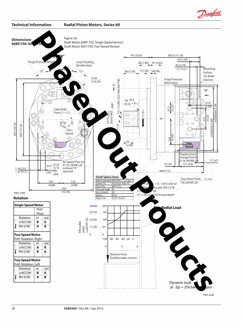
Technical Information Radial Piston Motors Series 60
5369264 bull Rev BA bull Sep 201328
Dimensions60M1750 60V1750
Figure 26 Shaft Motor 60M1750 Single Speed VersionShaft Motor 60V1750 Two Speed Version
Single Speed MotorPortFlow
Rotation in outLH(CCW) B ARH (CW) A B
Two Speed MotorPref Rotation Right
Rotation in outLH(CCW) A BRH (CW) B A
Two Speed MotorPref Rotation Left
Rotation in outLH(CCW) B ARH (CW) A B
View X
L2L1A
B
425
(16
73)
Purge Pressure Relief Valve
Case Drain Ports L1 + L2
Loop Flushing Shuttle Valve
x1
Two Speed
385
(15
16)
225 +025-010
(89) +01 -004
oslash075 Aoslash(03 ) A
30deg
for Speed Pick Up9 16-18UNF-2Binclined 15 degoptional
15deg15deg
15deg15deg
350(1378)
R 20 R (079)
124(488)
124(488)
138(543)
P001 430E
Rotation
X
Max Radial Load
Displacementchange Port X1716-20UNF-2B
24(94)15 (59)
oslash31
5-0
15
(Dia
124
02-0
06)
440(173)
2835 (1116)
48 (189)
90 (354)
12-
13 U
NC
X22
(86)
full
THD
381
(15
)
63(248)
141 (555)
R4 +02(R16 +01 )
97 (382)
Main Ports A + B 100-Code 62Split Flange Boss per SAE J 518716-14UNC-2B27 (106) min full thread depth
Case Drain Ports L1+L278-20UNF-2B
20 (079) ( L1+L2 )
50 (197)
MountingSurface for Brake (Option)Purge Pressure
Relief Valve
121 (48)
278(109)
572
(22
5)
oslash33
0(D
ia12
99)11
5 (4
53)
17 (67)
141
(55
5)
Two Speed
9 (35)
oslash35
0(D
ia13
78)
A
-100 -80 -60 -40 -20 0
-4 -2
200
100
150
0
50
Allo
wab
lera
dial
Loa
d kN
(lb)
Distance from Shaftshoulder mm (in)
0
22500
11250
33750
0
45000
P001 432E
Dynamic load at ∆p = 250 bar (3600 psi)
Shaft Spline Data5 ssalC a1129B ISNA Spline standard
Spline Fit Pitch Dia
03 elgnA erusserPNo of teethSplineMajor Dia
Flat Root Side Fit889 (35)
288169207 (3625)
Phased Out Products
Technical Information Radial Piston Motors Series 60
369264 bull Rev BA bull Sep 2013 29
NotesPhased Out Products
Technical Information Radial Piston Motors Series 60
5369264 bull Rev BA bull Sep 201330
DimensionsBrakes
Figure 27 Radial Piston Motor with Brake (0ptional)
P001 418E
Table 6 Brake Dimensions
Series Dimension
A B C
60M0470 23 (090) 74 (290) oslash212 (Dia 835)
60M0780 42 (165) 100 (394) oslash245 (Dia 965)
60M1048 30 (118) 90 (354) oslash280 (Dia 1102)
60M1750 38 (147) 107 (421) oslash320 (Dia 1260)
B
CX7
MountingFace
Mechanical BrakeRelease 1 to be used with Mech Brake Release 2
Mechanical BrakeRelease 2to be used with Mech Brake Release 1
A
Hydraulic BrakeRelease X7916-18UNF-2B
Mechanical BrakeRelease 1 to be used with Mech Brake Release 2
Mechanical BrakeRelease 2to be used with Mech Brake Release 1
TwoSpeed
X
View X
Phased Out Products
Technical Information Radial Piston Motors Series 60
369264 bull Rev BA bull Sep 2013 31
DimensionsSpeed Sensor
Figure 28 Radial Piston Motor with Speed Sensor (0ptional)
Section A - A (11)Speed Sensor
Connecto IdNoStraightRight angle
Connector is not supplied with the motorPlease order separatly using above Id No
Table 7 Speed Sensor Connector
Electrical details see page12
P001 444E
A
A
30deg 15 deg
31m
ax (1
22)
Pin 1Pin 2
Pin 3
Pin 4
Key Way
Wrench-Flats
Connector Insert
View Y
Y
127
(50)
500724500725
Phased Out Products
Comatrolwwwcomatrolcom
Schwarzmuumlller-Inverterwwwschwarzmueller-invertercom
Turolla wwwturollaocgcom
Valmovawwwvalmovacom
Hydro-Gear wwwhydro-gearcom
Daikin-Sauer-Danfosswwwdaikin-sauer-danfosscom
Danfoss Power Solutions is a global manufacturer and supplier of high-quality hydraulic and electronic components We specialize in providing state-of-the-art technology and solutions that excel in the harsh operating conditions of the mobile off -highway market Building on our extensive applications expertise we work closely with our customers to ensure exceptional performance for a broad range of off -highway vehicles
We help OEMs around the world speed up system development reduce costs and bring vehicles to market faster Danfoss ndash Your Strongest Partner in Mobile Hydraulics
Go to wwwpowersolutionsdanfosscom for further product information
Wherever off -highway vehicles are at work so is Danfoss
We off er expert worldwide support for our customers ensuring the best possible solutions for outstanding performance And with an extensive network of Global Service Partners we also provide comprehensive global service for all of our components
Please contact the Danfoss Power Solution representative nearest you
Products we off er
Bent Axis Motors
Closed Circuit Axial Piston Pumps and Motors
Displays
Electrohydraulic Power Steering
Electrohydraulics
Hydraulic Power Steering
Integrated Systems
Joysticks and Control Handles
Microcontrollers and Software
Open Circuit Axial Piston Pumps
Orbital Motors
PLUS+1reg GUIDE
Proportional Valves
Sensors
Steering
Transit Mixer Drives
Local address
Danfoss can accept no responsibility for possible errors in catalogues brochures and other printed material Danfoss reserves the right to alter its products without notice This also applies to products already on order provided that such alterations can be made without subsequential changes being necessary in specifications already agreedAll trademarks in this material are property of the respective companies Danfoss and the Danfoss logotype are trademarks of Danfoss AS All rights reserved
Danfoss Power Solutions22F Block C Yishan RdShanghai 200233 ChinaPhone +86 21 3418 5200
Danfoss Power Solutions GmbH amp Co OHGKrokamp 35D-24539 Neumuumlnster GermanyPhone +49 4321 871 0
Danfoss Power Solutions ApSNordborgvej 81DK-6430 Nordborg DenmarkPhone +45 7488 2222
Danfoss Power Solutions US Company2800 East 13th StreetAmes IA 50010 USAPhone +1 515 239 6000
369264 bull Rev BA bull Sep 2013 wwwdanfosscom copy Danfoss AS 2013-09
Phased Out Products
Technical Information Radial Piston Motors Series 60
369264 bull Rev BA bull Sep 2013 29
NotesPhased Out Products
Technical Information Radial Piston Motors Series 60
5369264 bull Rev BA bull Sep 201330
DimensionsBrakes
Figure 27 Radial Piston Motor with Brake (0ptional)
P001 418E
Table 6 Brake Dimensions
Series Dimension
A B C
60M0470 23 (090) 74 (290) oslash212 (Dia 835)
60M0780 42 (165) 100 (394) oslash245 (Dia 965)
60M1048 30 (118) 90 (354) oslash280 (Dia 1102)
60M1750 38 (147) 107 (421) oslash320 (Dia 1260)
B
CX7
MountingFace
Mechanical BrakeRelease 1 to be used with Mech Brake Release 2
Mechanical BrakeRelease 2to be used with Mech Brake Release 1
A
Hydraulic BrakeRelease X7916-18UNF-2B
Mechanical BrakeRelease 1 to be used with Mech Brake Release 2
Mechanical BrakeRelease 2to be used with Mech Brake Release 1
TwoSpeed
X
View X
Phased Out Products
Technical Information Radial Piston Motors Series 60
369264 bull Rev BA bull Sep 2013 31
DimensionsSpeed Sensor
Figure 28 Radial Piston Motor with Speed Sensor (0ptional)
Section A - A (11)Speed Sensor
Connecto IdNoStraightRight angle
Connector is not supplied with the motorPlease order separatly using above Id No
Table 7 Speed Sensor Connector
Electrical details see page12
P001 444E
A
A
30deg 15 deg
31m
ax (1
22)
Pin 1Pin 2
Pin 3
Pin 4
Key Way
Wrench-Flats
Connector Insert
View Y
Y
127
(50)
500724500725
Phased Out Products
Comatrolwwwcomatrolcom
Schwarzmuumlller-Inverterwwwschwarzmueller-invertercom
Turolla wwwturollaocgcom
Valmovawwwvalmovacom
Hydro-Gear wwwhydro-gearcom
Daikin-Sauer-Danfosswwwdaikin-sauer-danfosscom
Danfoss Power Solutions is a global manufacturer and supplier of high-quality hydraulic and electronic components We specialize in providing state-of-the-art technology and solutions that excel in the harsh operating conditions of the mobile off -highway market Building on our extensive applications expertise we work closely with our customers to ensure exceptional performance for a broad range of off -highway vehicles
We help OEMs around the world speed up system development reduce costs and bring vehicles to market faster Danfoss ndash Your Strongest Partner in Mobile Hydraulics
Go to wwwpowersolutionsdanfosscom for further product information
Wherever off -highway vehicles are at work so is Danfoss
We off er expert worldwide support for our customers ensuring the best possible solutions for outstanding performance And with an extensive network of Global Service Partners we also provide comprehensive global service for all of our components
Please contact the Danfoss Power Solution representative nearest you
Products we off er
Bent Axis Motors
Closed Circuit Axial Piston Pumps and Motors
Displays
Electrohydraulic Power Steering
Electrohydraulics
Hydraulic Power Steering
Integrated Systems
Joysticks and Control Handles
Microcontrollers and Software
Open Circuit Axial Piston Pumps
Orbital Motors
PLUS+1reg GUIDE
Proportional Valves
Sensors
Steering
Transit Mixer Drives
Local address
Danfoss can accept no responsibility for possible errors in catalogues brochures and other printed material Danfoss reserves the right to alter its products without notice This also applies to products already on order provided that such alterations can be made without subsequential changes being necessary in specifications already agreedAll trademarks in this material are property of the respective companies Danfoss and the Danfoss logotype are trademarks of Danfoss AS All rights reserved
Danfoss Power Solutions22F Block C Yishan RdShanghai 200233 ChinaPhone +86 21 3418 5200
Danfoss Power Solutions GmbH amp Co OHGKrokamp 35D-24539 Neumuumlnster GermanyPhone +49 4321 871 0
Danfoss Power Solutions ApSNordborgvej 81DK-6430 Nordborg DenmarkPhone +45 7488 2222
Danfoss Power Solutions US Company2800 East 13th StreetAmes IA 50010 USAPhone +1 515 239 6000
369264 bull Rev BA bull Sep 2013 wwwdanfosscom copy Danfoss AS 2013-09
Phased Out Products
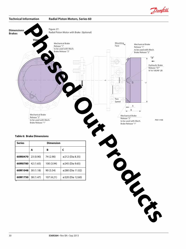
Technical Information Radial Piston Motors Series 60
5369264 bull Rev BA bull Sep 201330
DimensionsBrakes
Figure 27 Radial Piston Motor with Brake (0ptional)
P001 418E
Table 6 Brake Dimensions
Series Dimension
A B C
60M0470 23 (090) 74 (290) oslash212 (Dia 835)
60M0780 42 (165) 100 (394) oslash245 (Dia 965)
60M1048 30 (118) 90 (354) oslash280 (Dia 1102)
60M1750 38 (147) 107 (421) oslash320 (Dia 1260)
B
CX7
MountingFace
Mechanical BrakeRelease 1 to be used with Mech Brake Release 2
Mechanical BrakeRelease 2to be used with Mech Brake Release 1
A
Hydraulic BrakeRelease X7916-18UNF-2B
Mechanical BrakeRelease 1 to be used with Mech Brake Release 2
Mechanical BrakeRelease 2to be used with Mech Brake Release 1
TwoSpeed
X
View X
Phased Out Products
Technical Information Radial Piston Motors Series 60
369264 bull Rev BA bull Sep 2013 31
DimensionsSpeed Sensor
Figure 28 Radial Piston Motor with Speed Sensor (0ptional)
Section A - A (11)Speed Sensor
Connecto IdNoStraightRight angle
Connector is not supplied with the motorPlease order separatly using above Id No
Table 7 Speed Sensor Connector
Electrical details see page12
P001 444E
A
A
30deg 15 deg
31m
ax (1
22)
Pin 1Pin 2
Pin 3
Pin 4
Key Way
Wrench-Flats
Connector Insert
View Y
Y
127
(50)
500724500725
Phased Out Products
Comatrolwwwcomatrolcom
Schwarzmuumlller-Inverterwwwschwarzmueller-invertercom
Turolla wwwturollaocgcom
Valmovawwwvalmovacom
Hydro-Gear wwwhydro-gearcom
Daikin-Sauer-Danfosswwwdaikin-sauer-danfosscom
Danfoss Power Solutions is a global manufacturer and supplier of high-quality hydraulic and electronic components We specialize in providing state-of-the-art technology and solutions that excel in the harsh operating conditions of the mobile off -highway market Building on our extensive applications expertise we work closely with our customers to ensure exceptional performance for a broad range of off -highway vehicles
We help OEMs around the world speed up system development reduce costs and bring vehicles to market faster Danfoss ndash Your Strongest Partner in Mobile Hydraulics
Go to wwwpowersolutionsdanfosscom for further product information
Wherever off -highway vehicles are at work so is Danfoss
We off er expert worldwide support for our customers ensuring the best possible solutions for outstanding performance And with an extensive network of Global Service Partners we also provide comprehensive global service for all of our components
Please contact the Danfoss Power Solution representative nearest you
Products we off er
Bent Axis Motors
Closed Circuit Axial Piston Pumps and Motors
Displays
Electrohydraulic Power Steering
Electrohydraulics
Hydraulic Power Steering
Integrated Systems
Joysticks and Control Handles
Microcontrollers and Software
Open Circuit Axial Piston Pumps
Orbital Motors
PLUS+1reg GUIDE
Proportional Valves
Sensors
Steering
Transit Mixer Drives
Local address
Danfoss can accept no responsibility for possible errors in catalogues brochures and other printed material Danfoss reserves the right to alter its products without notice This also applies to products already on order provided that such alterations can be made without subsequential changes being necessary in specifications already agreedAll trademarks in this material are property of the respective companies Danfoss and the Danfoss logotype are trademarks of Danfoss AS All rights reserved
Danfoss Power Solutions22F Block C Yishan RdShanghai 200233 ChinaPhone +86 21 3418 5200
Danfoss Power Solutions GmbH amp Co OHGKrokamp 35D-24539 Neumuumlnster GermanyPhone +49 4321 871 0
Danfoss Power Solutions ApSNordborgvej 81DK-6430 Nordborg DenmarkPhone +45 7488 2222
Danfoss Power Solutions US Company2800 East 13th StreetAmes IA 50010 USAPhone +1 515 239 6000
369264 bull Rev BA bull Sep 2013 wwwdanfosscom copy Danfoss AS 2013-09
Phased Out Products
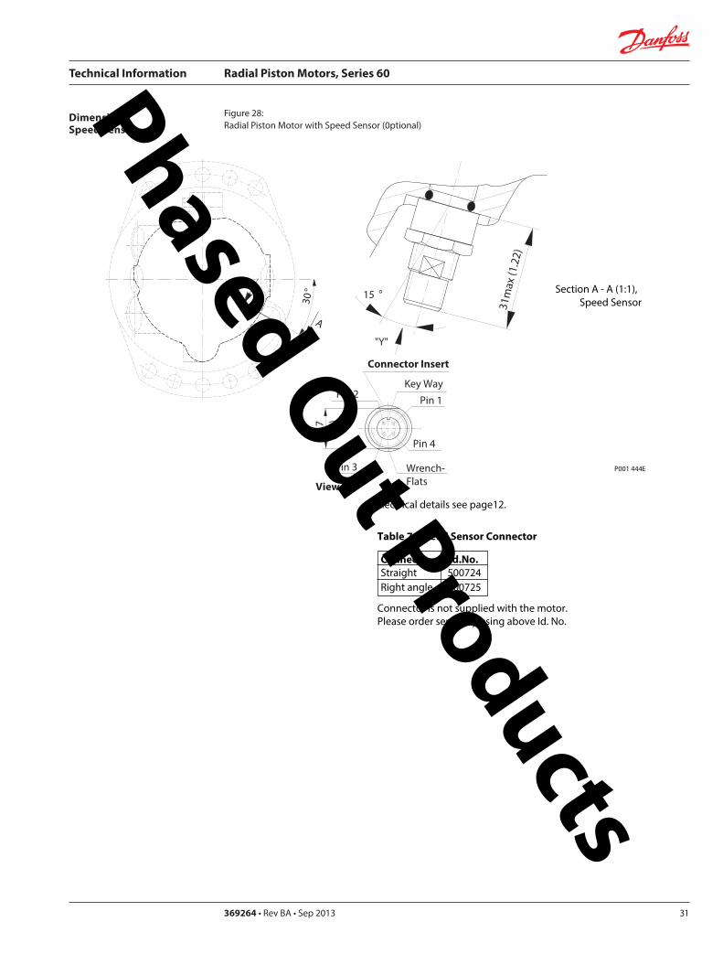
Technical Information Radial Piston Motors Series 60
369264 bull Rev BA bull Sep 2013 31
DimensionsSpeed Sensor
Figure 28 Radial Piston Motor with Speed Sensor (0ptional)
Section A - A (11)Speed Sensor
Connecto IdNoStraightRight angle
Connector is not supplied with the motorPlease order separatly using above Id No
Table 7 Speed Sensor Connector
Electrical details see page12
P001 444E
A
A
30deg 15 deg
31m
ax (1
22)
Pin 1Pin 2
Pin 3
Pin 4
Key Way
Wrench-Flats
Connector Insert
View Y
Y
127
(50)
500724500725
Phased Out Products
Comatrolwwwcomatrolcom
Schwarzmuumlller-Inverterwwwschwarzmueller-invertercom
Turolla wwwturollaocgcom
Valmovawwwvalmovacom
Hydro-Gear wwwhydro-gearcom
Daikin-Sauer-Danfosswwwdaikin-sauer-danfosscom
Danfoss Power Solutions is a global manufacturer and supplier of high-quality hydraulic and electronic components We specialize in providing state-of-the-art technology and solutions that excel in the harsh operating conditions of the mobile off -highway market Building on our extensive applications expertise we work closely with our customers to ensure exceptional performance for a broad range of off -highway vehicles
We help OEMs around the world speed up system development reduce costs and bring vehicles to market faster Danfoss ndash Your Strongest Partner in Mobile Hydraulics
Go to wwwpowersolutionsdanfosscom for further product information
Wherever off -highway vehicles are at work so is Danfoss
We off er expert worldwide support for our customers ensuring the best possible solutions for outstanding performance And with an extensive network of Global Service Partners we also provide comprehensive global service for all of our components
Please contact the Danfoss Power Solution representative nearest you
Products we off er
Bent Axis Motors
Closed Circuit Axial Piston Pumps and Motors
Displays
Electrohydraulic Power Steering
Electrohydraulics
Hydraulic Power Steering
Integrated Systems
Joysticks and Control Handles
Microcontrollers and Software
Open Circuit Axial Piston Pumps
Orbital Motors
PLUS+1reg GUIDE
Proportional Valves
Sensors
Steering
Transit Mixer Drives
Local address
Danfoss can accept no responsibility for possible errors in catalogues brochures and other printed material Danfoss reserves the right to alter its products without notice This also applies to products already on order provided that such alterations can be made without subsequential changes being necessary in specifications already agreedAll trademarks in this material are property of the respective companies Danfoss and the Danfoss logotype are trademarks of Danfoss AS All rights reserved
Danfoss Power Solutions22F Block C Yishan RdShanghai 200233 ChinaPhone +86 21 3418 5200
Danfoss Power Solutions GmbH amp Co OHGKrokamp 35D-24539 Neumuumlnster GermanyPhone +49 4321 871 0
Danfoss Power Solutions ApSNordborgvej 81DK-6430 Nordborg DenmarkPhone +45 7488 2222
Danfoss Power Solutions US Company2800 East 13th StreetAmes IA 50010 USAPhone +1 515 239 6000
369264 bull Rev BA bull Sep 2013 wwwdanfosscom copy Danfoss AS 2013-09
Phased Out Products