< Radhakrishna ...grouper.ieee.org/groups/802/20/Contribs/C802.20-05-79r1.pdf · IEEE...
40
R.Canchi, K. Murakami and M. Kitahara, KYOCERA Slide 1 IEEE C802.20-05/79r1 Submission The contributor is familiar with IEEE patent policy, as outlined in Section 6.3 of the IEEE-SA Standards Board Operations Manual <http://standards.ieee.org/guides/opman/sect6.html#6.3 > and in Understanding Patent Issues During IEEE Standards Development <http://standards.ieee.org/board/pat/guide.html >. Patent Policy The contributor grants a free, irrevocable license to the IEEE to incorporate material contained in this contribution, and any modifications thereof, in the creation of an IEEE Standards publication; to copyright in the IEEE’s name any IEEE Standards publication even though it may include portions of this contribution; and at the IEEE’s sole discretion to permit others to reproduce in whole or in part the resulting IEEE Standards publication. The contributor also acknowledges and accepts that this contribution may be made public by IEEE 802.20. Release This document has been prepared to assist the IEEE 802.20 Working Group. It is offered as a basis for discussion and is not binding on the contributing individual(s) or organization(s). The material in this document is subject to change in form and content after further study. The contributor(s) reserve(s) the right to add, amend or withdraw material contained herein. Notice To discus and Adopt MBTDD 625kHz MC Mode for Draft Specifications of IEEE802.20 MBWA Purpose This document presents the Technology Performance and Evaluation Criteria Report 1 of the Technology Proposal MBTDD 625k-MC for IEEE 802. 20 MBWA Abstract MBWA Call for Proposal Re: Voice: +1-408-952-4701 Fax: +1-408-954-8709 Email: [email protected] Voice: +81-45-943-6130 Fax: +81-45-943-6175 Email: [email protected] Voice: +81-45-943-6102 Fax: +81-45-943-6175 Email: [email protected] Radhakrishna Canchi KTRC, 2480 N. First Street #280 San Jose, CA 95131 Kazuhiro Murakami KYOCERA,2-1-1 Kagahara, Tsuzuki-ku, Yokohama, KANAGAWA 224-8502, JAPAN Miinako Kithara 2-1-1 Kagahara, Tsuzuki-ku, Yokohama, KANAGAWA 224-8502, JAPAN Source(s) 2006-JAN-06 Date Submitted MBTDD 625k-MC Mode (BEST-WINE) Performance Report 1 Presentation Title IEEE 802.20 Working Group on Mobile Broadband Wireless Access <http://grouper.ieee.org/groups/802/20/ > Project
Transcript of < Radhakrishna ...grouper.ieee.org/groups/802/20/Contribs/C802.20-05-79r1.pdf · IEEE...

R.Canchi, K. Murakami and M. Kitahara, KYOCERASlide 1
IEEE C802.20-05/79r1
Submission
The contributor is familiar with IEEE patent policy, as outlined in Section 6.3 of the IEEE-SA Standards Board Operations Manual<http://standards.ieee.org/guides/opman/sect6.html#6.3> and in Understanding Patent Issues During IEEE Standards Development<http://standards.ieee.org/board/pat/guide.html>.
Patent Policy
The contributor grants a free, irrevocable license to the IEEE to incorporate material contained in this contribution, and any modifications thereof, in the creation of an IEEE Standards publication; to copyright in the IEEE’s name any IEEE Standards publication even though it may includeportions of this contribution; and at the IEEE’s sole discretion to permit others to reproduce in whole or in part the resulting IEEE Standards publication. The contributor also acknowledges and accepts that this contribution may be made public by IEEE 802.20.
Release
This document has been prepared to assist the IEEE 802.20 Working Group. It is offered as a basis for discussion and is not binding on the contributing individual(s) or organization(s). The material in this document is subject to change in form and content after further study. The contributor(s) reserve(s) the right to add, amend or withdraw material contained herein.
Notice
To discus and Adopt MBTDD 625kHz MC Mode for Draft Specifications of IEEE802.20 MBWAPurpose
This document presents the Technology Performance and Evaluation Criteria Report 1 of the Technology Proposal MBTDD 625k-MC for IEEE 802. 20 MBWA
Abstract
MBWA Call for ProposalRe:
Voice: +1-408-952-4701Fax: +1-408-954-8709Email: [email protected]
Voice: +81-45-943-6130Fax: +81-45-943-6175Email: [email protected]
Voice: +81-45-943-6102Fax: +81-45-943-6175Email: [email protected]
Radhakrishna CanchiKTRC, 2480 N. First Street #280 San Jose, CA 95131
Kazuhiro MurakamiKYOCERA,2-1-1 Kagahara, Tsuzuki-ku, Yokohama, KANAGAWA 224-8502, JAPAN
Miinako Kithara2-1-1 Kagahara, Tsuzuki-ku, Yokohama, KANAGAWA 224-8502, JAPAN
Source(s)
2006-JAN-06Date Submitted
MBTDD 625k-MC Mode (BEST-WINE) Performance Report 1 PresentationTitle
IEEE 802.20 Working Group on Mobile Broadband Wireless Access <http://grouper.ieee.org/groups/802/20/>
Project

IEEE C802.20-05/79r1
Submission
MBTDD 625kMBTDD 625k--MC Mode MC Mode (BEST(BEST--WINE: WINE: BBroadband Mobilroadband MobilEESSpapaTTial ial WWireless ireless IInternterNNet Accet AccEEss )ss )Performance Report 1 PresentationPerformance Report 1 Presentation
IEEE 802.20 Plenary MeetingHawaii
January 16-19, 2006

R.Canchi, K. Murakami and M. Kitahara, KYOCERASlide 3
IEEE C802.20-05/79r1
Submission
ChangesChanges
• The title has been changed to MBTDD 625k-MC
• Slides with the Title underlined and highlighted show the changes in the Evaluation Report 1

R.Canchi, K. Murakami and M. Kitahara, KYOCERASlide 4
IEEE C802.20-05/79r1
Submission
MBTDD 625kMBTDD 625k--MC Mode MC Mode (BEST(BEST--WINE: WINE: BBroadband Mobilroadband MobilEE SSpapaTTial ial
WWireless ireless IInternterNNet Accet AccEEss )ss )
• Proposed Draft Technology Specifications■ Enhanced MAC Layer and PHY layer Draft
Specifications to the base specifications of HC-SDMA*■■ AND AND
● Base Technical Specifications “ATIS-PP-0700004-2005, High Capacity-Spatial Division Multiple Access (HC-SDMA)*”.
● * The copyright of this document is owned by the Alliance for Telecommunications Industry Solutions. Any request to reproduce this document, or portion thereof, shall be directed to ATIS, 1200 G Street, NW, Suite 500, Washington, DC 20005.
● * For Electronic Downloads, Paper Copy or CD-ROM please follow the link https://www.atis.org/atis/docstore/doc_display.asp?ID=3617

R.Canchi, K. Murakami and M. Kitahara, KYOCERASlide 5
IEEE C802.20-05/79r1
Submission
MBTDD 625kMBTDD 625k--MC MC (BEST(BEST--WINE)WINE)Technology Performance Technology Performance Outline of PresentationOutline of Presentation
• System Model• RF Parameters• Link budget• Basic PHY layer (link level) information• Simulation environment• Simulation Results
■ Link Level■ System Level
• Conclusion

R.Canchi, K. Murakami and M. Kitahara, KYOCERASlide 6
IEEE C802.20-05/79r1
Submission
System Calibration ModelSystem Calibration Model

R.Canchi, K. Murakami and M. Kitahara, KYOCERASlide 7
IEEE C802.20-05/79r1
Submission
System Lay out and and UT positionsSystem Lay out and and UT positions
-5
-4
-3
-2
-1
0
1
2
3
4
5
-5 -4 -3 -2 -1 0 1 2 3 4 5
-5
-4
-3
-2
-1
0
1
2
3
4
5
-6 -4 -2 0 2 4 6

R.Canchi, K. Murakami and M. Kitahara, KYOCERASlide 8
IEEE C802.20-05/79r1
Submission
RF ParametersRF Parameters
-58.5dBm-42.6dBm-39.1dBm
Mod 0 : -58.5 dBm Mod 8 : - 42.6 dBm Mod 10 : - 39.1 dBm
Receiver Blocking – MS (level of same technology blocking signal at frequency offset of 2 times Channel BW)
12[*]
-50.8 dBm-36.8 dBm-31.4 dBm
Mod 0 : -50.8 dBm Mod 7 : -36.8 dBm Mod 10 : -31.4 dBm
Receiver Blocking – BS (level of same technology blocking signal at frequency offset of 2 times Channel BW)
11[*]
30 dB27 dB25 dB
Mod 0 to 6 : 30 dB Mod 7 to 8 : 27 dB Mod 9 to 10 : 25 dB
Receiver Selectivity -- MS10*30 dBMod 1 /Mod 10 : 30 dBReceiver Selectivity -- BS9*
See link budgetSpecify at BER of 0.1%Receiver reference sensitivity (to be proposed by each technology)
810 dB10 dBReceiver noise figure -- MS75 dB5 dBReceiver noise figure -- BS6
35.4 dB36.8 dBACLR - Attenuation of emissions into an adjacent channel (same Ch BW) – MS
5*
50.2 dB43 dBACLR - Attenuation of emissions into an adjacent channel (same Ch BW) – BS
4*
-13 dBmAttenuation of the transmit power P by: 43
+10 log(P) dB
Out of Band emission limits – BS and MS (emission measured in 1 MHz resolution bandwidth)
3+27 dBm27 dBmTransmitter Power -- MS2+44 dBm43 dBm/MHzTransmitter Power -- BS1
2.5 MHzTDD - SYSTEM
Base Value1 MHz Channel
RF Parameter TDD System
#

R.Canchi, K. Murakami and M. Kitahara, KYOCERASlide 9
IEEE C802.20-05/79r1
Submission
MBTDD 625kMBTDD 625k--MC MC (BEST(BEST--WINE)WINE) SystemSystem’’s PHY s PHY and MAC Layer informationand MAC Layer information
• Channel Configuration
Specification
TDD
TDMA ・SDMA625 kHz
5 ms2usec
Uplink Time Slot slots 3Length 545 usPayload 182 symbols
Downlink Time Slot slots 3Length 1090 usPayload 494 symbols
500 ksps
Items
Symbol rate
Frame LenghtCarrier space
Mutiple AccessDuplexing
symbol duration
2.5MHz
frequency
625kHz

R.Canchi, K. Murakami and M. Kitahara, KYOCERASlide 10
IEEE C802.20-05/79r1
Submission
MBTDD 625kMBTDD 625k--MC MC (BEST(BEST--WINE)WINE) SystemSystem’’s s PHY and MAC Layer informationPHY and MAC Layer information
• Modulation classDown Link(Kbps) Up Link(Kbps)
ModClass ModulationMethod Data Rate
/Slot Data Rate
/Carrier Data Rate
/Slot Data Rate
/Carrier
0 BPSK 35 106 6 19 1 BPSK 50 149 13 38 2 QPSK 82 245 26 77 3 QPSK 126 379 43 130 4 8PSK 162 485 58 173 5 8PSK 198 595 72 216 6 12QAM 262 787 98 293 7 16QAM 307 922 115 346 8 24QAM 354 1061 133 398 9 32QAM 378 1133 142 427
10 64QAM 498 1493 190 571

R.Canchi, K. Murakami and M. Kitahara, KYOCERASlide 11
IEEE C802.20-05/79r1
Submission
Simulation Channel EnvironmentsSimulation Channel Environments
• Suburban Macro at 3KMPH – Pedestrian B
• Suburban Macro at 120 KMPH – Vehicular B

R.Canchi, K. Murakami and M. Kitahara, KYOCERASlide 12
IEEE C802.20-05/79r1
Submission
Basic PHY layer (link level) informationBasic PHY layer (link level) information
• Link Level simulation Parameters■ TDD /TDMA system■ 3 timeslot structure ■BS antenna number 12antennas ■UT antenna numbers
●Antennas used for transmission :1●Antennas used of receiving: 4
■Adaptive Array Antenna Algorithm : MMSE■Receiver equalizer.

R.Canchi, K. Murakami and M. Kitahara, KYOCERASlide 13
IEEE C802.20-05/79r1
Submission
Channel models used in Link Level SimulationsChannel models used in Link Level Simulations
Models case-iii case-iv PDP Pedestrian-B (Phase I)
Vehicular-B (Phase I)
Number of Paths 6 6 0 0 -2.5 0
-0.9 200 0 300 -4.9 800 -12.8 8900 -8.0 1200 -10.0 12900 -7.8 2300 -25.2 17100 Rel
ativ
e Pa
th p
ower
(d
B)
Del
ay (n
s)
-23.9 3700 -16.0 20000 Speed (km/h) 3 120
Topology 0.5λ 0.5λ PAS RMS angle spread of 35 degrees per
path with a Laplacian distribution RMS angle spread of 35 degrees per
path with a Laplacian distribution DoT (degrees) -22.5 22.5 M
obile
St
atio
n
AoA (degrees) 67.5 (all paths) 67.5 (all paths)
Topology 0.5λ-spacing PAS Laplacian distribution with RMS angle spread of 2 degrees per path
depending on AoA/AoD
Bas
e St
atio
n
AoD/AoA (degrees)
50ο for 2ο RMS angle spread per path 20ο for 5ο RMS angle spread per path

R.Canchi, K. Murakami and M. Kitahara, KYOCERASlide 14
IEEE C802.20-05/79r1
Submission
SubSub--path Spatial parameters AoD and AoA path Spatial parameters AoD and AoA offset offset
• sub-path AoD and AoA offset
Sub-path # (m) Offset for a 2 deg AS at BS(Macrocell)AoDmn ,,∆ (degrees)
Offset for a 35 deg AS atMS
AoAmn ,,∆ (degrees)
1, 2 ± 0.0894 ± 1.56493, 4 ± 0.2826 ± 4.94475, 6 ± 0.4984 ± 8.72247, 8 ± 0.7431 ± 13.0045
9, 10 ± 1.0257 ± 17.949211, 12 ± 1.3594 ± 23.789913, 14 ± 1.7688 ± 30.953815, 16 ± 2.2961 ± 40.182417, 18 ± 3.0389 ± 53.181619, 20 ± 4.3101 ± 75.4274

R.Canchi, K. Murakami and M. Kitahara, KYOCERASlide 15
IEEE C802.20-05/79r1
Submission
System level Simulation environmentSystem level Simulation environment
• simulation target featureTDD system3 timeslot structureSpatial Davison multiple Access feature (Max. 4 )Power controlLink adaptation

R.Canchi, K. Murakami and M. Kitahara, KYOCERASlide 16
IEEE C802.20-05/79r1
Submission
System level Simulation environmentSystem level Simulation environment
simulation parameters
• BS antenna number 12antennas (0.5λ) • UT antenna number 4antennas(0.5λ)• 19BS 3sector• BS max Tx power 39dBm/12ant • UT max Tx power 27dBm• BS antenna gain 17dBi • UT antenna gain 0dBi• BS NF 5dB• UT NF 10dB• Temperature 15℃• BS cable loss 3dB• UT body loss 3dB• Simulation (2.5MHz BW= 625kHz ×4carrier)

R.Canchi, K. Murakami and M. Kitahara, KYOCERASlide 17
IEEE C802.20-05/79r1
Submission
System level simulation channel modelSystem level simulation channel modelChannel Scenario Suburban MacroNumber of paths (N) 6Number of sub-paths (M) per-path 20Mean AS at BS E[ ASσ ] =50
AS at BS as a lognormal RV( )10 ^ , ~ (0,1)AS AS ASx xσ = ε +µ η
ASµ = 0.69
ASε = 0.13
ASAoDASr σσ= / 1.2Per-path AS at BS (Fixed) 20
BS per-path AoD Distribution standarddistribution
),0( 2AoDση where
ASASAoD r σ=σ
Mean AS at MS E[σAS, MS] = 680
Per-path AS at MS (fixed) 350
MS Per-path AoA Distribution (Pr)),0( 2AoAση
Delay spread as a lognormal RV ( )10 ^ , ~ (0,1)DS DS DSx xσ = ε +µ η
µDS = - 6.80εDS = 0.288
Mean total RMS Delay Spread E[ DSσ ] = 0.17 µs
DSdelaysDSr σσ= / 1.4
Distribution for path delaysLognormal shadowing standard deviation 10dBPathloss model (dB), d is in meters 31.5 + 35log10(d)

R.Canchi, K. Murakami and M. Kitahara, KYOCERASlide 18
IEEE C802.20-05/79r1
Submission
Link level simulation ResultLink level simulation Result
• Uplink (Vehicular B model) FER vs. SINR Performance
0.01
0.1
1
-5 0 5 10 15 20 25 30
sinr [dB]
fer
120km/h mod7
120km/h mod6120km/h mod5
120km/h mod4
120km/h mod3 120km/h mod2
120km/h mod1
120km/h mod0

R.Canchi, K. Murakami and M. Kitahara, KYOCERASlide 19
IEEE C802.20-05/79r1
Submission
Link level simulation ResultLink level simulation Result
• Downlink (Vehicular B model) FER vs. SINR Performance
0.01
0.1
1
- 10 - 5 0 5 10 15 20 25 30
SINR[dB]
FER
120km/h mod8
120km/h mod7
120km/h mod6
120km/h mod5
120km/h mod4
120km/h mod3
120km/h mod2
120km/h mod1
120km/h mod0

R.Canchi, K. Murakami and M. Kitahara, KYOCERASlide 20
IEEE C802.20-05/79r1
Submission
Link level simulation ResultLink level simulation Result
• Uplink (Pedestrian B model) FER vs. SINR Performance
0.01
0.1
1
-10 -5 0 5 10 15 20 25 30
sinr [dB]
fer
3km/h mod7
3km/h mod6 3km/h mod5
3km/h mod4
3km/h mod3
3km/h mod23km/h mod1
3km/h mod0

R.Canchi, K. Murakami and M. Kitahara, KYOCERASlide 21
IEEE C802.20-05/79r1
Submission
Link level simulation ResultLink level simulation Result
• Downlink (PedestrianB model) FER vs. SINR Performance
0.01
0.1
1
- 10 - 5 0 5 10 15 20 25 30
SINR[dB]
FER
3km/ h mod83km/ h mod73km/ h mod63km/ h mod53km/ h mod43km/ h mod33km/ h mod23km/ h mod13km/ h mod0
R.Canchi, K. Murakami and M. Kitahara, KYOCERASlide 22
IEEE C802.20-05/79r1
Submission
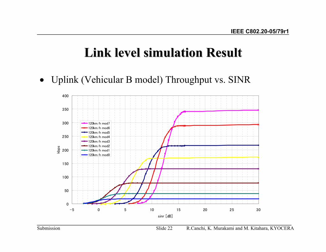
Link level simulation ResultLink level simulation Result
• Uplink (Vehicular B model) Throughput vs. SINR
0
50
100
150
200
250
300
350
400
-5 0 5 10 15 20 25 30
sinr [dB]
kbps
120km/h mod7
120km/h mod6
120km/h mod5120km/h mod4
120km/h mod3
120km/h mod2120km/h mod1
120km/h mod0
R.Canchi, K. Murakami and M. Kitahara, KYOCERASlide 23
IEEE C802.20-05/79r1
Submission
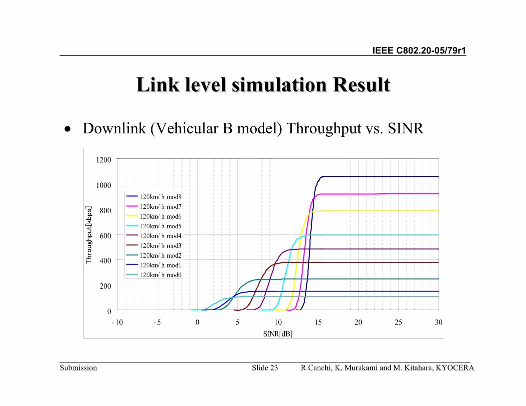
Link level simulation ResultLink level simulation Result
• Downlink (Vehicular B model) Throughput vs. SINR
0
200
400
600
800
1000
1200
- 10 - 5 0 5 10 15 20 25 30SINR[dB]
Thro
ugh
put[
kbps]
120km/ h mod8120km/ h mod7120km/ h mod6120km/ h mod5120km/ h mod4120km/ h mod3120km/ h mod2120km/ h mod1120km/ h mod0

R.Canchi, K. Murakami and M. Kitahara, KYOCERASlide 24
IEEE C802.20-05/79r1
Submission
Link level simulation ResultLink level simulation Result
• Uplink (Pedestrian B model) Throughput vs. SINR
0
50
100
150
200
250
300
350
400
-10 -5 0 5 10 15 20 25 30
sinr [dB]
kbps
3km/h mod7
3km/h mod6
3km/h mod5 3km/h mod4
3km/h mod3
3km/h mod23km/h mod1
3km/h mod0

R.Canchi, K. Murakami and M. Kitahara, KYOCERASlide 25
IEEE C802.20-05/79r1
Submission
Link level simulation ResultLink level simulation Result
• Downlink (Pedestrian B model) Throughput vs. SINR
0
200
400
600
800
1000
1200
- 10 - 5 0 5 10 15 20 25 30SINR[dB]
Thro
ugh
put[
kbps
]
3km/ h mod83km/ h mod73km/ h mod63km/ h mod53km/ h mod43km/ h mod33km/ h mod23km/ h mod13km/ h mod0

R.Canchi, K. Murakami and M. Kitahara, KYOCERASlide 26
IEEE C802.20-05/79r1
Submission
System level simulation calibration result
System level simulation calibration condition and parameters
Number of paths: 1Environment: Suburban macroNumber of BS & MS antenna: 1Inter BS separation 2.5kmNumber of carriers: 1(625kHz). 1 user/timeslot @sector
• user1 @ (-60, R/2) intimeslot1• user2 @ (0,R/2) in timeslot2• user3 @ (60, R) in timeslot3• (degree, distance from the BS)

R.Canchi, K. Murakami and M. Kitahara, KYOCERASlide 27
IEEE C802.20-05/79r1
Submission
• 120km/h User Date Rate CDF
System level simulation resultSystem level simulation result
Uplink
Downlink
0
0.1
0.2
0.3
0.4
0.5
0.6
0.7
0.8
0.9
1
0 200 400 600 800 1000 1200 1400
Throughput (kbps)
Pro
babi
lity
Up
Down
10% o f use rs experience <=136 kbps
[Up/Down]
Prob
abilit
yThroughput (kbps)

R.Canchi, K. Murakami and M. Kitahara, KYOCERASlide 28
IEEE C802.20-05/79r1
Submission
0
0.1
0.2
0.3
0.4
0.5
0.6
0.7
0.8
0.9
1
0 200 400 600 800 1000 1200 1400
Throughpu t (kbps)P
roba
bilit
y
Up
Down
10% of users expe rience <=467 kbps
[Down]
10% of users experience <=170 kbps
[Up]
• 3km/h User Date Rate CDF
Uplink
Downlink
Prob
abilit
yThroughput (kbps)
System level simulation resultSystem level simulation result

R.Canchi, K. Murakami and M. Kitahara, KYOCERASlide 29
IEEE C802.20-05/79r1
Submission
• Load User vs. Base station SeparationDownlink -3 Kmph

R.Canchi, K. Murakami and M. Kitahara, KYOCERASlide 30
IEEE C802.20-05/79r1
Submission
• Load User vs. Base station SeparationDownlink -120 Kmph

R.Canchi, K. Murakami and M. Kitahara, KYOCERASlide 31
IEEE C802.20-05/79r1
Submission
• Load User vs Base station SeparationUplink -3 Kmph

R.Canchi, K. Murakami and M. Kitahara, KYOCERASlide 32
IEEE C802.20-05/79r1
Submission
• Load User vs Base station SeparationUplink - 120 Kmph

R.Canchi, K. Murakami and M. Kitahara, KYOCERASlide 33
IEEE C802.20-05/79r1
Submission
• Aggregate throughput vs Base station SeparationDownlink - 3 Kmph
R.Canchi, K. Murakami and M. Kitahara, KYOCERASlide 34
IEEE C802.20-05/79r1
Submission
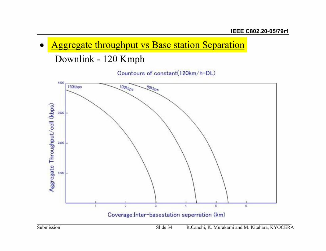
• Aggregate throughput vs Base station SeparationDownlink - 120 Kmph

R.Canchi, K. Murakami and M. Kitahara, KYOCERASlide 35
IEEE C802.20-05/79r1
Submission
• Aggregate throughput vs Base station SeparationUplink - 3 Kmph

R.Canchi, K. Murakami and M. Kitahara, KYOCERASlide 36
IEEE C802.20-05/79r1
Submission
• Aggregate throughput vs Base station SeparationUplink - 120 Kmph

R.Canchi, K. Murakami and M. Kitahara, KYOCERASlide 37
IEEE C802.20-05/79r1
Submission
• Fairness criteriaThe CDF of the Normalized throughput with Respect to average user throughputwas determined for Cell radius 1km.
Table 7-1 Suburban Pedestrian B Case
Table 7-2 Suburban Vehicular B Case
1.128%0.823%<0.50.013%0.006%<0.20.002%0.001%<0.1
DownlinkUplinkNormalized throughput with Respect to average user throughput
9.310%1.257%<0.51.738%0.017%<0.20.887%0.003%<0.1
DownlinkUplinkNormalized throughput with Respect to average user throughput

R.Canchi, K. Murakami and M. Kitahara, KYOCERASlide 38
IEEE C802.20-05/79r1
Submission
Summary ResultsSummary Results--SimulationSimulation
1.6994.063Downlink
2.4793.018Uplink
Spectral Efficiency @Vehicular B
Spectral Efficiency @pedestrian B

IEEE C802.20-05/79r1
Submission
AppendixAppendix
Practical System Results
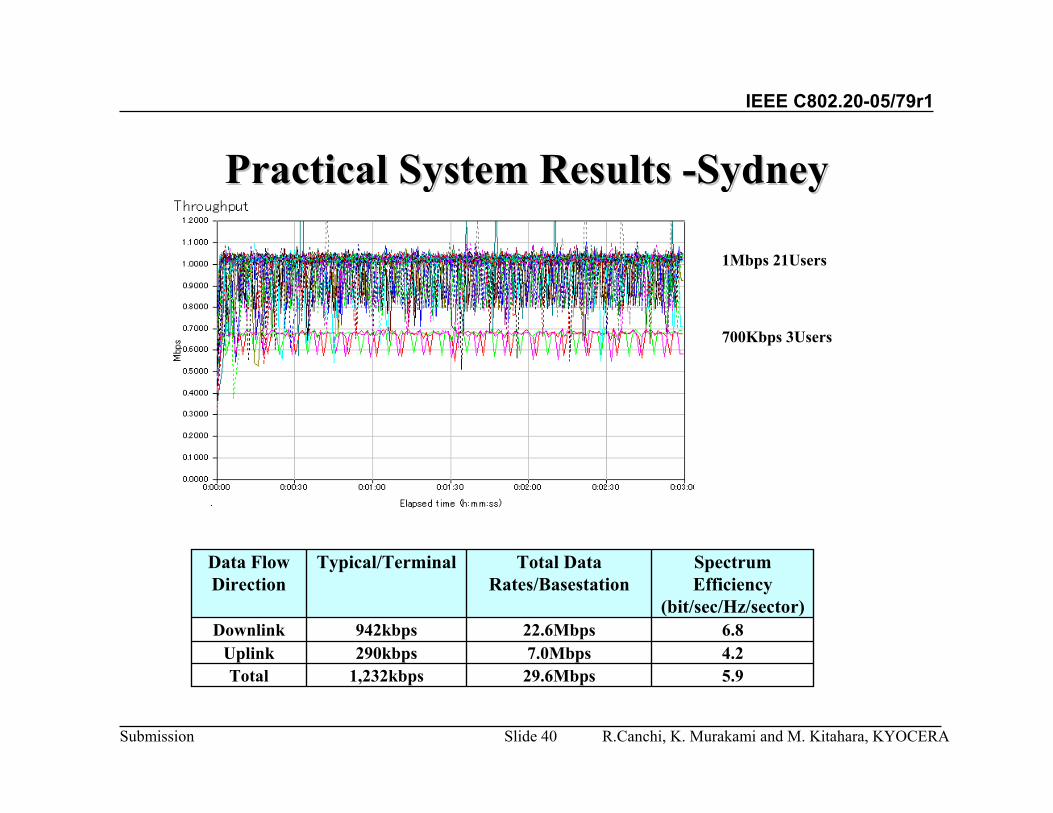
R.Canchi, K. Murakami and M. Kitahara, KYOCERASlide 40
IEEE C802.20-05/79r1
Submission
Practical System Results Practical System Results --SydneySydney
1Mbps 21Users
700Kbps 3Users
5.929.6Mbps1,232kbpsTotal4.27.0Mbps290kbpsUplink6.822.6Mbps942kbpsDownlink
Spectrum Efficiency
(bit/sec/Hz/sector)
Total Data Rates/Basestation
Typical/TerminalData Flow Direction