
Project IEEE 802.20 Working Group on Mobile Broadband...
34
2007-03-11 IEEE C802.20-07/09 1 Project IEEE 802.20 Working Group on Mobile Broadband Wireless Access <http://grouper.ieee.org/groups/802/20/ > Title UMBFDD Draft Technology Overview Date Submitted 2007-3-5 (5 March 2007) Source(s) Al Jette Voice: 1 (847) 632-4201 Email: [email protected] Shirish Nagaraj Voice: 1 (847) 632-2362Email: [email protected] Val Oprescu Voice: 1 (847) 435-0053 Email: [email protected] Re: MBWA Call for Proposals (802.20 - 07/02) Abstract This contribution provides a high-level presentation of the UMBFDD proposal. Purpose For consideration by 802.20 as it evaluates proposals for FDD MBWA. Notice This document has been prepared to assist the IEEE 802.20 Working Group. It is offered as a basis for discussion and is not binding on the contributing individual(s) or organization(s). The material in this document is subject to change in form and content after further study. The contributor(s) reserve(s) the right to add, amend or withdraw material contained herein. Release The contributor grants a free, irrevocable license to the IEEE to incorporate material contained in this contribution, and any modifications thereof, in the creation of an IEEE Standards publication; to copyright in the IEEE’s name any IEEE Standards publication even though it may include portions of this contribution; and at the IEEE’s sole discretion to permit others to reproduce in whole or in part the resulting IEEE Standards publication. The contributor also acknowledges and accepts that this contribution may be made public by IEEE 802.20. Patent Policy The contributor is familiar with IEEE patent policy, as outlined in Section 6.3 of the IEEE-SA Standards Board Operations Manual <http://standards.ieee.org/guides/opman/sect6.html#6.3 > and in Understanding Patent Issues During IEEE Standards Development <http://standards.ieee.org/board/pat/guide.html >.
Transcript of Project IEEE 802.20 Working Group on Mobile Broadband...
2007-03-11 IEEE C802.20-07/09
1
Project IEEE 802.20 Working Group on Mobile Broadband Wireless Access
<http://grouper.ieee.org/groups/802/20/>
Title UMBFDD Draft Technology Overview
Date Submitted 2007-3-5 (5 March 2007)
Source(s) Al Jette Voice: 1 (847) 632-4201 Email: [email protected]
Shirish Nagaraj Voice: 1 (847) 632-2362Email:
Val Oprescu
Voice: 1 (847) 435-0053
Email: [email protected]
Re: MBWA Call for Proposals (802.20 - 07/02)
Abstract This contribution provides a high-level presentation of the UMBFDD proposal.
Purpose For consideration by 802.20 as it evaluates proposals for FDD MBWA.
Notice This document has been prepared to assist the IEEE 802.20 Working Group. It is offered as a basis for discussion and is not binding on the contributing individual(s) or organization(s). The material in this document is subject to change in form and content after further study. The contributor(s) reserve(s) the right to add, amend or withdraw material contained herein.
Release The contributor grants a free, irrevocable license to the IEEE to incorporate material contained in this contribution, and any modifications thereof, in the creation of an IEEE Standards publication; to copyright in the IEEE’s name any IEEE Standards publication even though it may include portions of this contribution; and at the IEEE’s sole discretion to permit others to reproduce in whole or in part the resulting IEEE Standards publication. The contributor also acknowledges and accepts that this contribution may be made public by IEEE 802.20.
Patent Policy
The contributor is familiar with IEEE patent policy, as outlined in Section 6.3 of the IEEE-SA Standards Board Operations Manual <http://standards.ieee.org/guides/opman/sect6.html#6.3> and in Understanding Patent Issues During IEEE Standards Development <http://standards.ieee.org/board/pat/guide.html>.
2007-03-11 IEEE C802.20-07/09
2
UMBFDD Candidate Proposal for IEEE 802.20
he Ultra Mobile Broadband FDD (UMBFDD) proposal is being submitted to IEEE 802.20 as a candidate air interface technology. It represents a complete FDD proposal, fully compliant with the approved Project Authorization Request (PAR)
and detailed requirements that have been developed by the 802.20. UMBFDD consists of the applicable 3GPP2’s UMBTM air interface specifications, which are targeted for initial publication in April 2007. The drafting of the specifications, which has been going on since at least July 2006, has been carried out by a large and diverse group of influential industry players, inclusive of both manufacturers and operators. Prior to acceptance in the specification, proposals have undergone rigorous scrutiny and consensus-building modifications. At the time of the drafting of this paper, the UMBTM specifications have already gone through the Revise and Freeze phase and have been sent to 3GPP2’s organizational partners (standards development organizations in various regions) for final approval. The UMBTM set of specifications (see Table 1) consists of almost 1200 pages across ten documents covering the Physical, Data Link and Upper Layers of the air interface. The text is “Stage 3”, i.e. implementable requirements, containing specific language which identifies mandatory and optional features on both the fixed infrastructure and the mobile units. The description of functionality is highly modularized, with modules, called “protocols”, grouped in “layers” and “planes”. In general, protocol data units move up and down the stack across layers, while the “planes” handle primarily control information. Modules are considered “basic” or “default”, since, especially at higher layers, they are theoretically replaceable by alternative protocols that perform the functionality in a different manner. Modules communicate with homologous modules across the air interface via “headers” and “messages”. They also communicate with modules on the same side of the air interface, not necessarily in the same functional layer or plane, by accepting (and executing) ”commands” and by issuing “indications”. Information common to several modules can be stored and maintained statically or dynamically as “public data”. Protocols are designed to work as state machines having defined transitions between states. Protocols can have several instances at the same time, with functional sets of instances being grouped in distinct “personalities”.
Between certain layers, abstract interfaces using Service Access Points (SAPs) and primitives are defined.
UMBFDD at a glance
A system consists of a set of multi-sectored fixed transceivers ( called Access Networks or ANs ) in two-way radio communications with a set of mobile transceivers (Access Terminals or ATs). The ANs may or may not be synchronized with each other, but in general, sectors of the same AN are viewed as always being synchronized. Each
T
2007-03-11 IEEE C802.20-07/09
3
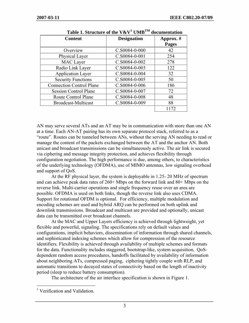
Table 1. Structure of the V&V1 UMBTM documentation Content Designation Approx. #
Pages Overview C.S0084-0-000 42
Physical Layer C.S0084-0-001 254 MAC Layer C.S0084-0-002 278
Radio Link Layer C.S0084-0-003 122 Application Layer C.S0084-0-004 32 Security Functions C.S0084-0-005 50
Connection Control Plane C.S0084-0-006 186 Session Control Plane C.S0084-0-007 72 Route Control Plane C.S0084-0-008 48 Broadcast-Multicast C.S0084-0-009 88
1172
AN may serve several ATs and an AT may be in communication with more than one AN at a time. Each AN-AT pairing has its own separate protocol stack, referred to as a “route”. Routes can be tunneled between ANs, without the serving AN needing to read or manage the content of the packets exchanged between the AT and the anchor AN. Both unicast and broadcast transmissions can be simultaneously active. The air link is secured via ciphering and message integrity protection, and achieves flexibility through configuration negotiation. The high performance is due, among others, to characteristics of the underlying technology (OFDMA), use of MIMO antennas, low signaling overhead and support of QoS.
At the RF physical layer, the system is deployable in 1.25- 20 MHz of spectrum and can achieve peak data rates of 260+ Mbps on the forward link and 80+ Mbps on the reverse link. Multi-carrier operations and single frequency reuse over an area are possible. OFDMA is used on both links, though the reverse link also uses CDMA. Support for rotational OFDM is optional. For efficiency, multiple modulation and encoding schemes are used and hybrid ARQ can be performed on both uplink and downlink transmissions. Broadcast and multicast are provided and optionally, unicast data can be transmitted over broadcast channels.
At the MAC and Upper Layers efficiency is achieved through lightweight, yet flexible and powerful, signaling. The specifications rely on default values and configurations, implicit behaviors, dissemination of information through shared channels, and sophisticated indexing schemes which allow for compression of the resource identifiers. Flexibility is achieved through availability of multiple schemes and formats for the data. Functionality includes staggered, bootstrap-like, system acquisition, QoS-dependent random access procedures, handoffs facilitated by availability of information about neighboring ATs, compressed paging, ciphering tightly couple with RLP, and automatic transitions to decayed states of connectivity based on the length of inactivity period (sleep to reduce battery consumption).
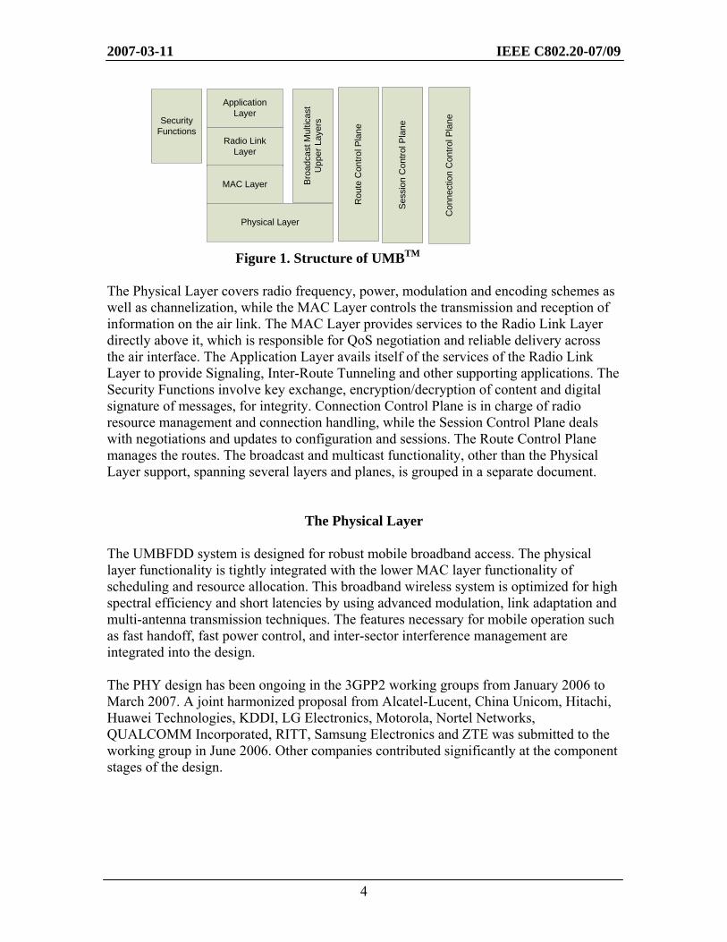
The architecture of the air interface specification is shown in Figure 1. 1 Verification and Validation.
2007-03-11 IEEE C802.20-07/09
4
Figure 1. Structure of UMBTM
The Physical Layer covers radio frequency, power, modulation and encoding schemes as well as channelization, while the MAC Layer controls the transmission and reception of information on the air link. The MAC Layer provides services to the Radio Link Layer directly above it, which is responsible for QoS negotiation and reliable delivery across the air interface. The Application Layer avails itself of the services of the Radio Link Layer to provide Signaling, Inter-Route Tunneling and other supporting applications. The Security Functions involve key exchange, encryption/decryption of content and digital signature of messages, for integrity. Connection Control Plane is in charge of radio resource management and connection handling, while the Session Control Plane deals with negotiations and updates to configuration and sessions. The Route Control Plane manages the routes. The broadcast and multicast functionality, other than the Physical Layer support, spanning several layers and planes, is grouped in a separate document.
The Physical Layer The UMBFDD system is designed for robust mobile broadband access. The physical layer functionality is tightly integrated with the lower MAC layer functionality of scheduling and resource allocation. This broadband wireless system is optimized for high spectral efficiency and short latencies by using advanced modulation, link adaptation and multi-antenna transmission techniques. The features necessary for mobile operation such as fast handoff, fast power control, and inter-sector interference management are integrated into the design. The PHY design has been ongoing in the 3GPP2 working groups from January 2006 to March 2007. A joint harmonized proposal from Alcatel-Lucent, China Unicom, Hitachi, Huawei Technologies, KDDI, LG Electronics, Motorola, Nortel Networks, QUALCOMM Incorporated, RITT, Samsung Electronics and ZTE was submitted to the working group in June 2006. Other companies contributed significantly at the component stages of the design.
Application Layer
Radio Link Layer
MAC Layer
Physical Layer
Sess
ion
Con
trol P
lane
Con
nect
ion
Con
trol P
laneSecurity
Functions
Rou
te C
ontro
l Pla
ne
Broa
dcas
t Mul
ticas
t U
pper
Lay
ers
2007-03-11 IEEE C802.20-07/09
5
PHY Overview The design is scalable in bandwidth with fine granularity from 1.25 to 20 MHz. The system uses adaptive coding and modulation with resource adaptive synchronous H-ARQ and turbo coding. Modulations supported include QPSK, 16-QAM, 8-PSK and 64-QAM. A short HARQ re-transmission latency of approximately 7 ms is supported on both forward and reverse links. The system allows for subband scheduling which exhibits enhanced performance and shows multi-user diversity gains for latency-sensitive traffic. The OFDMA forward link features MIMO and open loop transmit diversity, with support for the following: single codeword MIMO with closed loop rate and rank adaptation (SCW), multi-codeword (layered) MIMO with per-layer rate adaptation (MCW), and STTD. Efficient use of frequency diversity and frequency-selective transmission on both links results in optimized trade-offs for different channel and traffic mixes. Further, precoding and SDMA (multi-user MIMO) are supported. Significant effort has been made to make significant improvements to VoIP capacity. Signaling enhancements, such as group resource allocation (GRA), result in very high VoIP capacity. Further, dynamic sharing of sources between data and control is also permitted for improved resource utilization. The reverse link supports quasi-orthogonal transmissions. The orthogonal transmissions are based on OFDMA, while non-orthogonal transmissions are based on layer superposed OFDMA (LS-OFDMA) and SDMA. The precoded CDMA reverse link segment allows for statistical multiplexing of various control channels. It has optional support for low-rate data transmissions which are subject to AT capabilities. Fast access and fast request with reduced overhead are also supported using the CDMA control segment. In addition, an OFDMA control channel is also provided, which can be used for highly periodic control transmissions such as channel quality indications (CQI). The CDMA pilot provides a broadband reference for power control and sub-band scheduling. It has efficient handoff support and has optimized throughput / fairness tradeoff through power control. The distributed power control is based on other cell interference indications. Interference management through fractional frequency reuse is also supported. This results in improved coverage and edge user performance. Dynamic fractional frequency reuse can be used to optimize bandwidth utilization. The system allows for efficient handoff support with FL softer handoff group selection, which improves edge user performance. Independent switching of FL and RL serving sectors is also allowed. Rotational OFDM transmissions are optionally supported. The OFDMA numerology is as shown in Table 2. A Superframe on the forward link consists of a superframe preamble followed by 25 PHY Frames. Each PHY Frame and the superframe preamble consist of 8 OFDM symbols. The first RL PHY Frame in a superframe is elongated (16 OFDM symbols) so as to align the forward and reverse links. The superframe preamble carries acquisition pilots and overhead channels for initial acquisition. A guard time of 78.13 ms is inserted
2007-03-11 IEEE C802.20-07/09
6
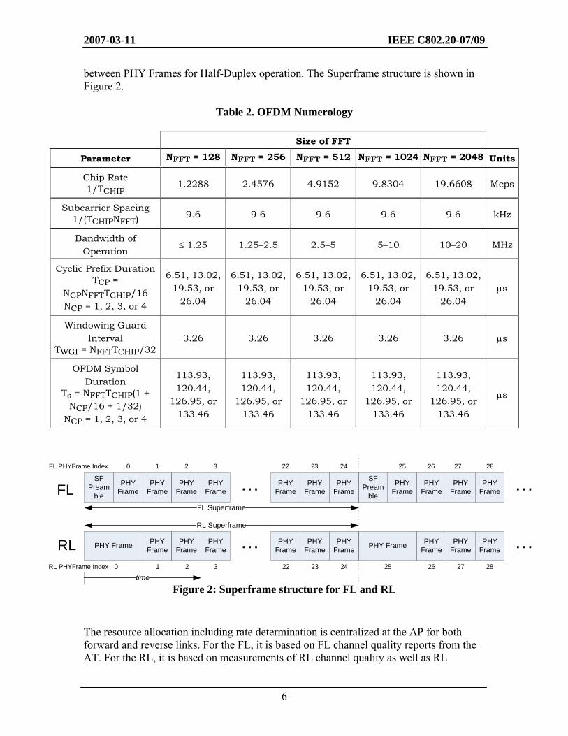
between PHY Frames for Half-Duplex operation. The Superframe structure is shown in Figure 2.
Table 2. OFDM Numerology
Size of FFT
Parameter NFFT = 128 NFFT = 256 NFFT = 512 NFFT = 1024 NFFT = 2048 Units
Chip Rate 1/TCHIP 1.2288 2.4576 4.9152 9.8304 19.6608 Mcps
Subcarrier Spacing 1/(TCHIPNFFT) 9.6 9.6 9.6 9.6 9.6 kHz
Bandwidth of Operation
≤ 1.25 1.25–2.5 2.5–5 5–10 10–20 MHz
Cyclic Prefix Duration TCP =
NCPNFFTTCHIP/16 NCP = 1, 2, 3, or 4
6.51, 13.02, 19.53, or
26.04
6.51, 13.02, 19.53, or
26.04
6.51, 13.02, 19.53, or
26.04
6.51, 13.02, 19.53, or
26.04
6.51, 13.02, 19.53, or
26.04 μs
Windowing Guard Interval
TWGI = NFFTTCHIP/32 3.26 3.26 3.26 3.26 3.26 μs
OFDM Symbol Duration
Ts = NFFTTCHIP(1 + NCP/16 + 1/32)
NCP = 1, 2, 3, or 4
113.93, 120.44,
126.95, or 133.46
113.93, 120.44,
126.95, or 133.46
113.93, 120.44,
126.95, or 133.46
113.93, 120.44,
126.95, or 133.46
113.93, 120.44,
126.95, or 133.46
μs
Figure 2: Superframe structure for FL and RL The resource allocation including rate determination is centralized at the AP for both forward and reverse links. For the FL, it is based on FL channel quality reports from the AT. For the RL, it is based on measurements of RL channel quality as well as RL
FL
RL
FL Superframe
PHY Frame
RL Superframe
PHY Frame
PHY Frame
PHY Frame
PHY Frame PHY Frame
PHY Frame
PHY Frame
PHY Frame
PHY Frame
PHY Frame
PHY Frame
…
…
0 1 2 3 22 23
0 1 2 3 22 23
PHY Frame
PHY Frame
PHY Frame
PHY Frame
PHY Frame PHY Frame
PHY Frame
PHY Frame
…
…
24 25 26 27
24 25 26 27
time
FL PHYFrame Index
RL PHYFrame Index
SF Pream
ble
SF Pream
ble
PHY Frame
PHY Frame
28
28
2007-03-11 IEEE C802.20-07/09
7
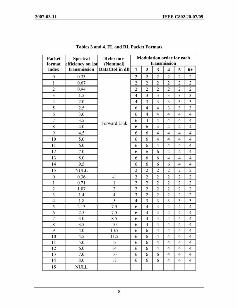
feedback from the AT including resource requests. The network assigns FL and RL resources via the Shared Control Channel (F-SCCH). The CDMA traffic resource allocation is AT-centric (autonomous) once a CDMA traffic zone has been allocated by the AP. The scheduler tries to maximize system capacity, manage QoS requirements such as the AT throughput and latency, and maintain fairness across ATs with widely disparate channel qualities. The design ensures that the scheduler has information required to utilize features such as sub-band scheduling, fractional frequency reuse, precoding, and SDMA to achieve the above goals. The CDMA traffic zone transmissions allow for bursty low-bit rate traffic and cell-edge users to communicate without explicitly being scheduled by the AP. The CDMA resource allocation is semi-static at the AP. The fundamental unit of assignment is logical subcarrier. This is a static resource that maps to a unique physical subcarrier. The mapping of logical subcarriers to physical subcarriers can change over time (hopping). Sets of logical subcarriers are specified using nodes on a channel tree. Each base node addresses 1 channel unit. The channel unit is 16 tones over 1 PHY Frame (minimum resource allocation unit). Each HARQ transmission follows at a fixed duration after the previous one. The assignments can be persistent or non-persistent. Non-persistent assignments expire after one packet, while persistent assignments persist until supplemented, decremented, de-assigned or packet loss. Persistent assignments reduce signaling requirements when multiple users are scheduled simultaneously. It can also be used to eliminate request latency for RL assignments. Grouped Resource allocation (GRA) via bitmap signaling provides efficient support of VoIP-like applications. The rate 1/3 convolutional code for block lengths is ≤ 128. The rate 1/5 turbo code for block lengths is > 128. The code is punctured or repeated to achieve the desired code rate. Synchronous HARQ on both links uses a channel interleaver. It is based on bit-reversal. It provides almost-regular puncture patterns and good interleaver distance properties at all code rates. The packet formats support the following modulation formats QPSK, 8PSK, 16QAM, 64QAM. It also supports a wide range of spectral efficiencies. Modulation step-down is used at high spectral efficiencies; here later HARQ transmissions use lower order modulation. This avoids repetition of coded bits and gains up to 1 dB for later transmissions. The packet formats supported in the forward and reverse links are shown in the Tables 3 and 4. Forward Link PHY Details A description of the FL pilot, control and data channels is given in Table 5. The control channels are of two types: the ones transmitted in the superframe preamble, which are used for system acquisition, broadcast information and quick paging, and others that are transmitted in regular PHY frames, which are used for supporting data scheduling and resource allocation.
2007-03-11 IEEE C802.20-07/09
8
Tables 3 and 4. FL and RL Packet Formats
Modulation order for each transmission
Packet format index
Spectral efficiency on 1st
transmission
Reference (Nominal)
DataCtoI in dB 1 2 3 4 5 6+ 0 0.33 2 2 2 2 2 2 1 0.67 2 2 2 2 2 2 2 0.94 2 2 2 2 2 2 3 1.5 4 3 3 3 3 3 4 2.0 4 3 3 3 3 3 5 2.5 6 4 4 3 3 3 6 3.0 6 4 4 4 4 4 7 3.5 6 4 4 4 4 4 8 4.0 6 6 4 4 4 4 9 4.5 6 6 4 4 4 4 10 5.0 6 6 4 4 4 4 11 6.0 6 6 4 4 4 4 12 7.0 6 6 6 4 4 4 13 8.0 6 6 6 4 4 4 14 9.5 6 6 6 6 4 4 15 NULL
Forward Link
2 2 2 2 2 2 0 0.36 -1 2 2 2 2 2 2 1 0.71 1 2 2 2 2 2 2 2 1.07 2 2 2 2 2 2 2 3 1.4 4 3 2 2 2 2 2 4 1.8 5 4 3 3 3 3 3 5 2.13 7.5 6 4 4 4 4 4 6 2.5 7.5 6 4 4 4 4 4 7 3.0 8.5 6 4 4 4 4 4 8 3.5 10 6 4 4 4 4 4 9 4.0 10.5 6 6 4 4 4 4 10 4.5 11.5 6 6 4 4 4 4 11 5.0 13 6 6 4 4 4 4 12 6.0 14 6 6 4 4 4 4 13 7.0 16 6 6 6 4 4 4 14 8.0 17 6 6 6 4 4 4 15 NULL
2007-03-11 IEEE C802.20-07/09
9
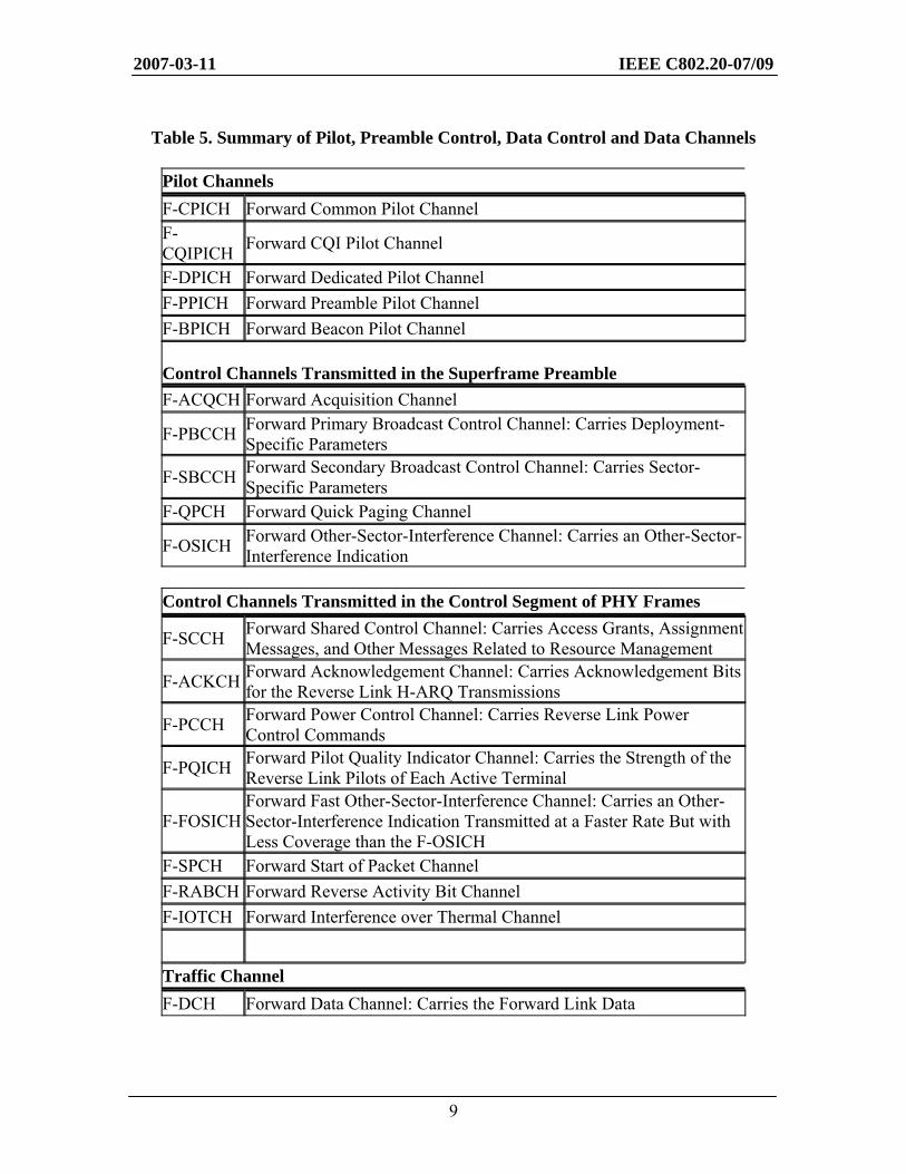
Table 5. Summary of Pilot, Preamble Control, Data Control and Data Channels
Pilot Channels F-CPICH Forward Common Pilot Channel F-CQIPICH Forward CQI Pilot Channel
F-DPICH Forward Dedicated Pilot Channel F-PPICH Forward Preamble Pilot Channel F-BPICH Forward Beacon Pilot Channel Control Channels Transmitted in the Superframe Preamble F-ACQCH Forward Acquisition Channel
F-PBCCH Forward Primary Broadcast Control Channel: Carries Deployment-Specific Parameters
F-SBCCH Forward Secondary Broadcast Control Channel: Carries Sector-Specific Parameters
F-QPCH Forward Quick Paging Channel
F-OSICH Forward Other-Sector-Interference Channel: Carries an Other-Sector-Interference Indication
Control Channels Transmitted in the Control Segment of PHY Frames
F-SCCH Forward Shared Control Channel: Carries Access Grants, Assignment Messages, and Other Messages Related to Resource Management
F-ACKCH Forward Acknowledgement Channel: Carries Acknowledgement Bits for the Reverse Link H-ARQ Transmissions
F-PCCH Forward Power Control Channel: Carries Reverse Link Power Control Commands
F-PQICH Forward Pilot Quality Indicator Channel: Carries the Strength of the Reverse Link Pilots of Each Active Terminal
F-FOSICH Forward Fast Other-Sector-Interference Channel: Carries an Other-Sector-Interference Indication Transmitted at a Faster Rate But with Less Coverage than the F-OSICH
F-SPCH Forward Start of Packet Channel F-RABCH Forward Reverse Activity Bit Channel F-IOTCH Forward Interference over Thermal Channel
Traffic Channel F-DCH Forward Data Channel: Carries the Forward Link Data
2007-03-11 IEEE C802.20-07/09
10
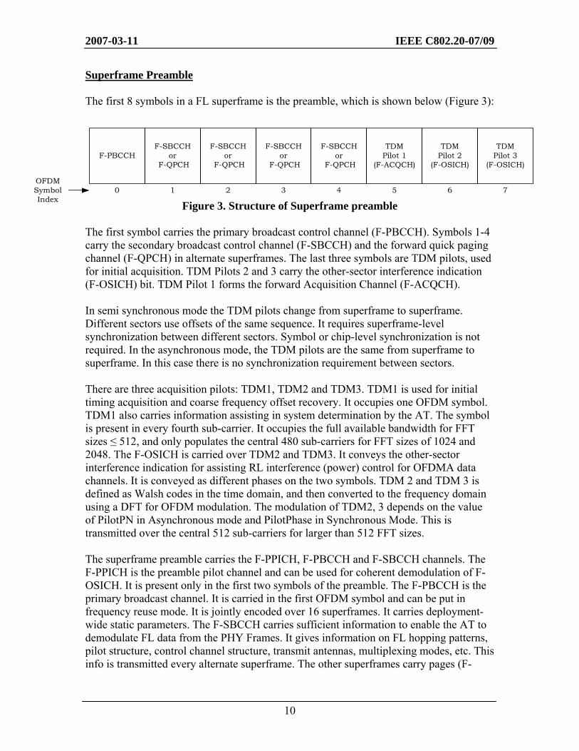
Superframe Preamble The first 8 symbols in a FL superframe is the preamble, which is shown below (Figure 3):
Figure 3. Structure of Superframe preamble The first symbol carries the primary broadcast control channel (F-PBCCH). Symbols 1-4 carry the secondary broadcast control channel (F-SBCCH) and the forward quick paging channel (F-QPCH) in alternate superframes. The last three symbols are TDM pilots, used for initial acquisition. TDM Pilots 2 and 3 carry the other-sector interference indication (F-OSICH) bit. TDM Pilot 1 forms the forward Acquisition Channel (F-ACQCH). In semi synchronous mode the TDM pilots change from superframe to superframe. Different sectors use offsets of the same sequence. It requires superframe-level synchronization between different sectors. Symbol or chip-level synchronization is not required. In the asynchronous mode, the TDM pilots are the same from superframe to superframe. In this case there is no synchronization requirement between sectors. There are three acquisition pilots: TDM1, TDM2 and TDM3. TDM1 is used for initial timing acquisition and coarse frequency offset recovery. It occupies one OFDM symbol. TDM1 also carries information assisting in system determination by the AT. The symbol is present in every fourth sub-carrier. It occupies the full available bandwidth for FFT sizes ≤ 512, and only populates the central 480 sub-carriers for FFT sizes of 1024 and 2048. The F-OSICH is carried over TDM2 and TDM3. It conveys the other-sector interference indication for assisting RL interference (power) control for OFDMA data channels. It is conveyed as different phases on the two symbols. TDM 2 and TDM 3 is defined as Walsh codes in the time domain, and then converted to the frequency domain using a DFT for OFDM modulation. The modulation of TDM2, 3 depends on the value of PilotPN in Asynchronous mode and PilotPhase in Synchronous Mode. This is transmitted over the central 512 sub-carriers for larger than 512 FFT sizes. The superframe preamble carries the F-PPICH, F-PBCCH and F-SBCCH channels. The F-PPICH is the preamble pilot channel and can be used for coherent demodulation of F-OSICH. It is present only in the first two symbols of the preamble. The F-PBCCH is the primary broadcast channel. It is carried in the first OFDM symbol and can be put in frequency reuse mode. It is jointly encoded over 16 superframes. It carries deployment-wide static parameters. The F-SBCCH carries sufficient information to enable the AT to demodulate FL data from the PHY Frames. It gives information on FL hopping patterns, pilot structure, control channel structure, transmit antennas, multiplexing modes, etc. This info is transmitted every alternate superframe. The other superframes carry pages (F-
TDMPilot 1
(F-ACQCH)
5
TDMPilot 2
(F-OSICH)
6
TDMPilot 3
(F-OSICH)
7
F-SBCCHor
F-QPCH
4
F-PBCCH
0
F-SBCCHor
F-QPCH
2
F-SBCCHor
F-QPCH
1
F-SBCCHor
F-QPCH
3OFDM Symbol Index
2007-03-11 IEEE C802.20-07/09
11
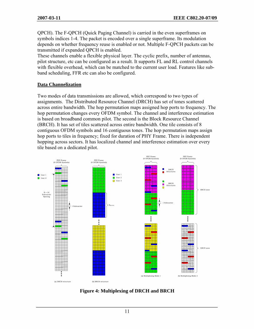
QPCH). The F-QPCH (Quick Paging Channel) is carried in the even superframes on symbols indices 1-4. The packet is encoded over a single superframe. Its modulation depends on whether frequency reuse is enabled or not. Multiple F-QPCH packets can be transmitted if expanded QPCH is enabled. These channels enable a flexible physical layer. The cyclic prefix, number of antennas, pilot structure, etc can be configured as a result. It supports FL and RL control channels with flexible overhead, which can be matched to the current user load. Features like sub-band scheduling, FFR etc can also be configured. Data Channelization Two modes of data transmissions are allowed, which correspond to two types of assignments. The Distributed Resource Channel (DRCH) has set of tones scattered across entire bandwidth. The hop permutation maps assigned hop ports to frequency. The hop permutation changes every OFDM symbol. The channel and interference estimation is based on broadband common pilot. The second is the Block Resource Channel (BRCH). It has set of tiles scattered across entire bandwidth. One tile consists of 8 contiguous OFDM symbols and 16 contiguous tones. The hop permutation maps assign hop ports to tiles in frequency; fixed for duration of PHY Frame. There is independent hopping across sectors. It has localized channel and interference estimation over every tile based on a dedicated pilot.
Figure 4: Multiplexing of DRCH and BRCH
PHY Frame(8 OFDM Symbols)
NBLOCK
User 1
User 2
User 3
PHY Frame(8 OFDM Symbols)
N = 34Subcarrier
Spacing
1 Subcarrier
User 1
User 2
(a) DRCH structure (b) BRCH structure
PHY Frame(8 OFDM Symbols)
PHY Frame(8 OFDM Symbols)
1 Subcarrier
(a) Multiplexing Mode 1 (b) Multiplexing Mode 2
BRCH zone
DRCH Structures
BRCH Structures
DRCH zone
2007-03-11 IEEE C802.20-07/09
12
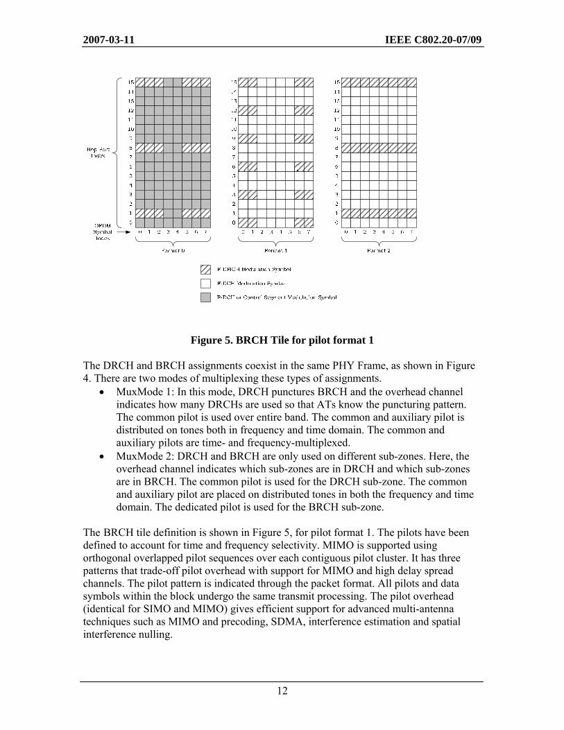
Figure 5. BRCH Tile for pilot format 1 The DRCH and BRCH assignments coexist in the same PHY Frame, as shown in Figure 4. There are two modes of multiplexing these types of assignments.
• MuxMode 1: In this mode, DRCH punctures BRCH and the overhead channel indicates how many DRCHs are used so that ATs know the puncturing pattern. The common pilot is used over entire band. The common and auxiliary pilot is distributed on tones both in frequency and time domain. The common and auxiliary pilots are time- and frequency-multiplexed.
• MuxMode 2: DRCH and BRCH are only used on different sub-zones. Here, the overhead channel indicates which sub-zones are in DRCH and which sub-zones are in BRCH. The common pilot is used for the DRCH sub-zone. The common and auxiliary pilot are placed on distributed tones in both the frequency and time domain. The dedicated pilot is used for the BRCH sub-zone.
The BRCH tile definition is shown in Figure 5, for pilot format 1. The pilots have been defined to account for time and frequency selectivity. MIMO is supported using orthogonal overlapped pilot sequences over each contiguous pilot cluster. It has three patterns that trade-off pilot overhead with support for MIMO and high delay spread channels. The pilot pattern is indicated through the packet format. All pilots and data symbols within the block undergo the same transmit processing. The pilot overhead (identical for SIMO and MIMO) gives efficient support for advanced multi-antenna techniques such as MIMO and precoding, SDMA, interference estimation and spatial interference nulling.
2007-03-11 IEEE C802.20-07/09
13
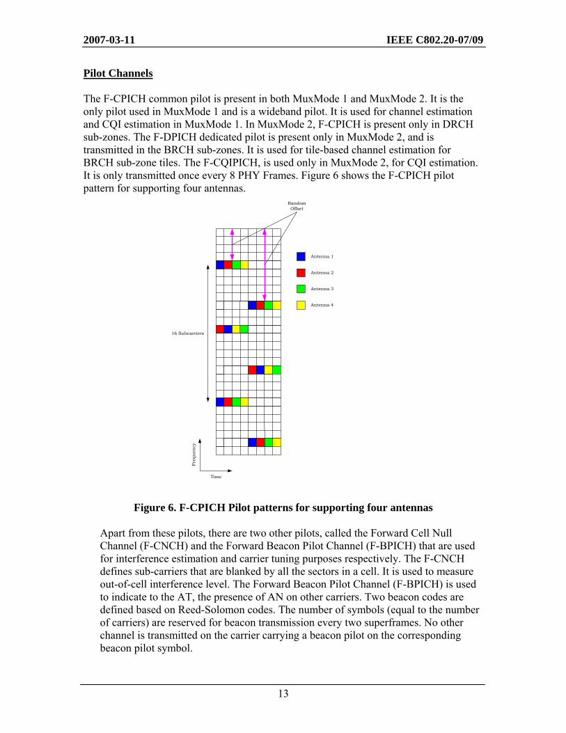
Pilot Channels The F-CPICH common pilot is present in both MuxMode 1 and MuxMode 2. It is the only pilot used in MuxMode 1 and is a wideband pilot. It is used for channel estimation and CQI estimation in MuxMode 1. In MuxMode 2, F-CPICH is present only in DRCH sub-zones. The F-DPICH dedicated pilot is present only in MuxMode 2, and is transmitted in the BRCH sub-zones. It is used for tile-based channel estimation for BRCH sub-zone tiles. The F-CQIPICH, is used only in MuxMode 2, for CQI estimation. It is only transmitted once every 8 PHY Frames. Figure 6 shows the F-CPICH pilot pattern for supporting four antennas.
Figure 6. F-CPICH Pilot patterns for supporting four antennas
Apart from these pilots, there are two other pilots, called the Forward Cell Null Channel (F-CNCH) and the Forward Beacon Pilot Channel (F-BPICH) that are used for interference estimation and carrier tuning purposes respectively. The F-CNCH defines sub-carriers that are blanked by all the sectors in a cell. It is used to measure out-of-cell interference level. The Forward Beacon Pilot Channel (F-BPICH) is used to indicate to the AT, the presence of AN on other carriers. Two beacon codes are defined based on Reed-Solomon codes. The number of symbols (equal to the number of carriers) are reserved for beacon transmission every two superframes. No other channel is transmitted on the carrier carrying a beacon pilot on the corresponding beacon pilot symbol.
Antenna 1
16 Subcarriers
Antenna 2
Antenna 3
Antenna 4
RandomOffset
Freq
uen
cy
Time
2007-03-11 IEEE C802.20-07/09
14
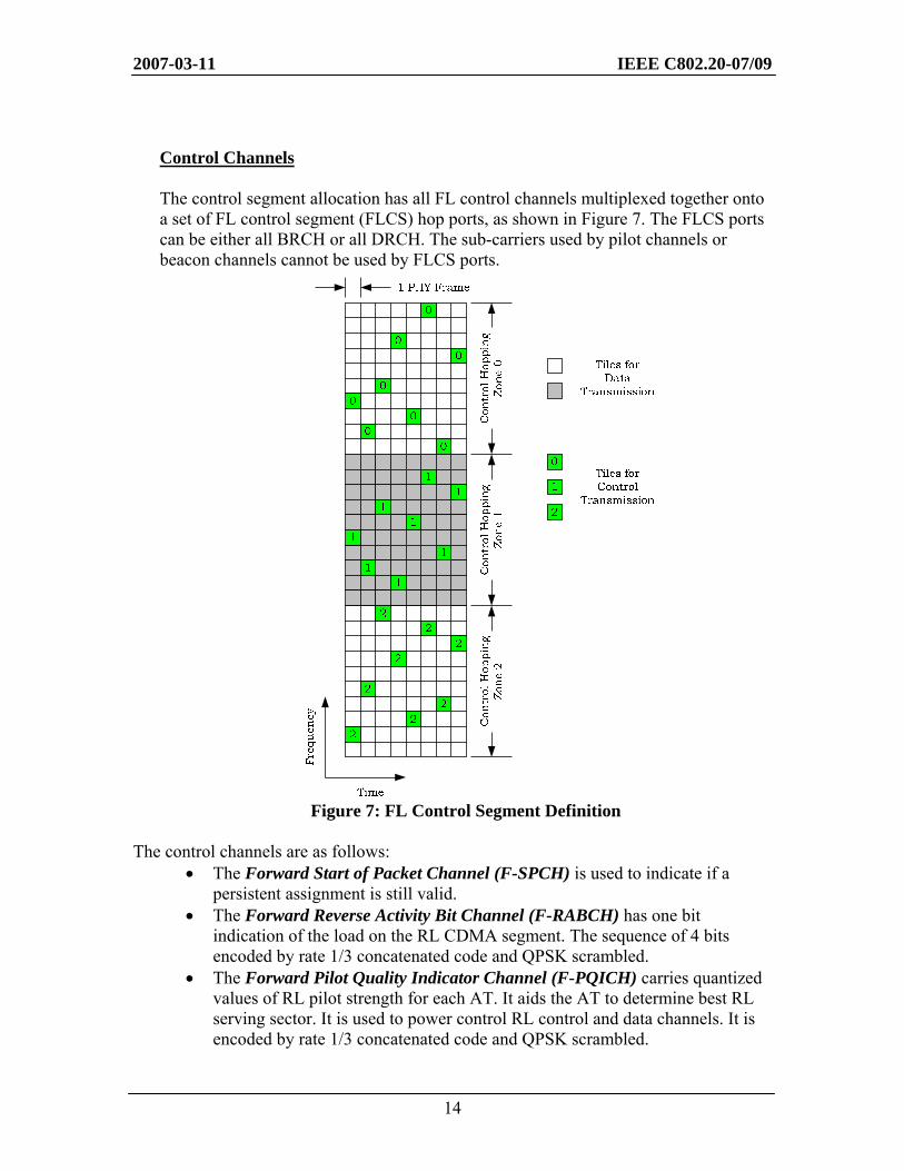
Control Channels The control segment allocation has all FL control channels multiplexed together onto a set of FL control segment (FLCS) hop ports, as shown in Figure 7. The FLCS ports can be either all BRCH or all DRCH. The sub-carriers used by pilot channels or beacon channels cannot be used by FLCS ports.
Figure 7: FL Control Segment Definition The control channels are as follows:
• The Forward Start of Packet Channel (F-SPCH) is used to indicate if a persistent assignment is still valid.
• The Forward Reverse Activity Bit Channel (F-RABCH) has one bit indication of the load on the RL CDMA segment. The sequence of 4 bits encoded by rate 1/3 concatenated code and QPSK scrambled.
• The Forward Pilot Quality Indicator Channel (F-PQICH) carries quantized values of RL pilot strength for each AT. It aids the AT to determine best RL serving sector. It is used to power control RL control and data channels. It is encoded by rate 1/3 concatenated code and QPSK scrambled.
2007-03-11 IEEE C802.20-07/09
15
• The Forward Fast Other Sector Interference Channel (F-FOSICH) is used for fast indications of interference levels. It is encoded by rate 1/3 concatenated code and QPSK scrambled.
• The Forward Interference Over Thermal Channel (F-IOTCH) is used for indications of interference levels on a given sub-band. It is encoded by rate 1/3 concatenated code and QPSK scrambled.
• The Forward Power Control Channel (F-PCCH) has one bit up/down power control command for RL CDMA control channel transmit power.
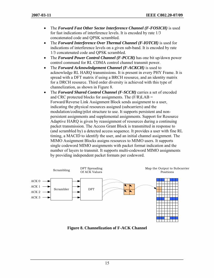
• The Forward Acknowledgement Channel (F-ACKCH) is used to acknowledge RL HARQ transmissions. It is present in every PHY Frame. It is spread with a DFT matrix if using a BRCH resource, and an identity matrix for a DRCH resource. Third order diversity is achieved with this type of channelization, as shown in Figure 8.
• The Forward Shared Control Channel (F-SCCH) carries a set of encoded and CRC protected blocks for assignments. The (F/R)LAB = Forward/Reverse Link Assignment Block sends assignment to a user, indicating the physical resources assigned (subcarriers) and the modulation/coding/pilot structure to use. It supports persistent and non-persistent assignments and supplemental assignments. Support for Resource Adaptive HARQ is given by reassignment of resources during a continuing packet transmission. The Access Grant Block is transmitted in response to (and scrambled by) a detected access sequence. It provides a user with fine RL timing, a MACID to identify the user, and an initial channel assignment. The MIMO Assignment Blocks assigns resources to MIMO users. It supports single codeword MIMO assignments with packet format indication and the number of layers to transmit. It supports multi-codeword MIMO assignments by providing independent packet formats per codeword.
Figure 8. Channelization of F-ACK Channel
DFTScrambler
ACK 3
ACK 0
ACK 1
ACK 2
Scrambling DFT SpreadingOf ACK Values
Map the Output to Subcarrier Positions
2007-03-11 IEEE C802.20-07/09
16
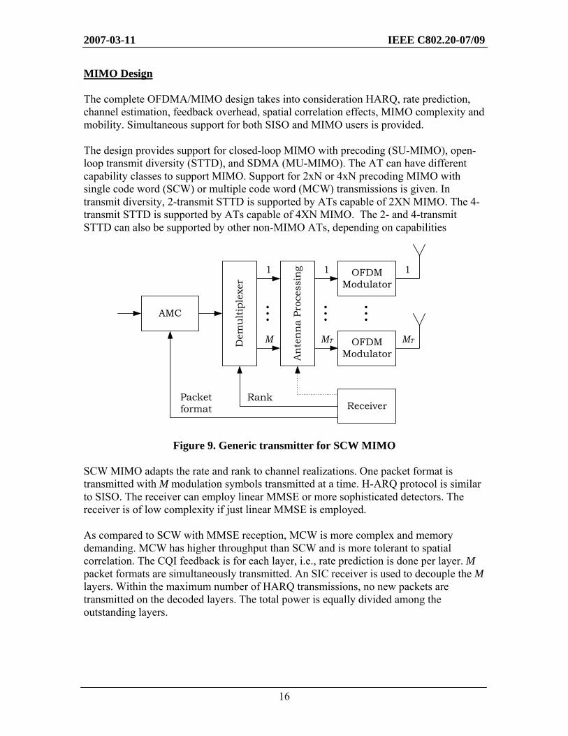
MIMO Design The complete OFDMA/MIMO design takes into consideration HARQ, rate prediction, channel estimation, feedback overhead, spatial correlation effects, MIMO complexity and mobility. Simultaneous support for both SISO and MIMO users is provided. The design provides support for closed-loop MIMO with precoding (SU-MIMO), open-loop transmit diversity (STTD), and SDMA (MU-MIMO). The AT can have different capability classes to support MIMO. Support for 2xN or 4xN precoding MIMO with single code word (SCW) or multiple code word (MCW) transmissions is given. In transmit diversity, 2-transmit STTD is supported by ATs capable of 2XN MIMO. The 4-transmit STTD is supported by ATs capable of 4XN MIMO. The 2- and 4-transmit STTD can also be supported by other non-MIMO ATs, depending on capabilities
Figure 9. Generic transmitter for SCW MIMO SCW MIMO adapts the rate and rank to channel realizations. One packet format is transmitted with M modulation symbols transmitted at a time. H-ARQ protocol is similar to SISO. The receiver can employ linear MMSE or more sophisticated detectors. The receiver is of low complexity if just linear MMSE is employed. As compared to SCW with MMSE reception, MCW is more complex and memory demanding. MCW has higher throughput than SCW and is more tolerant to spatial correlation. The CQI feedback is for each layer, i.e., rate prediction is done per layer. M packet formats are simultaneously transmitted. An SIC receiver is used to decouple the M layers. Within the maximum number of HARQ transmissions, no new packets are transmitted on the decoded layers. The total power is equally divided among the outstanding layers.
AMC
Dem
ult
iple
xer
An
ten
na
Proc
essi
ng OFDM
Modulator
OFDM Modulator
Receiver
.........
Packet format
Rank
1
MT
1
M
1
MT
2007-03-11 IEEE C802.20-07/09
17
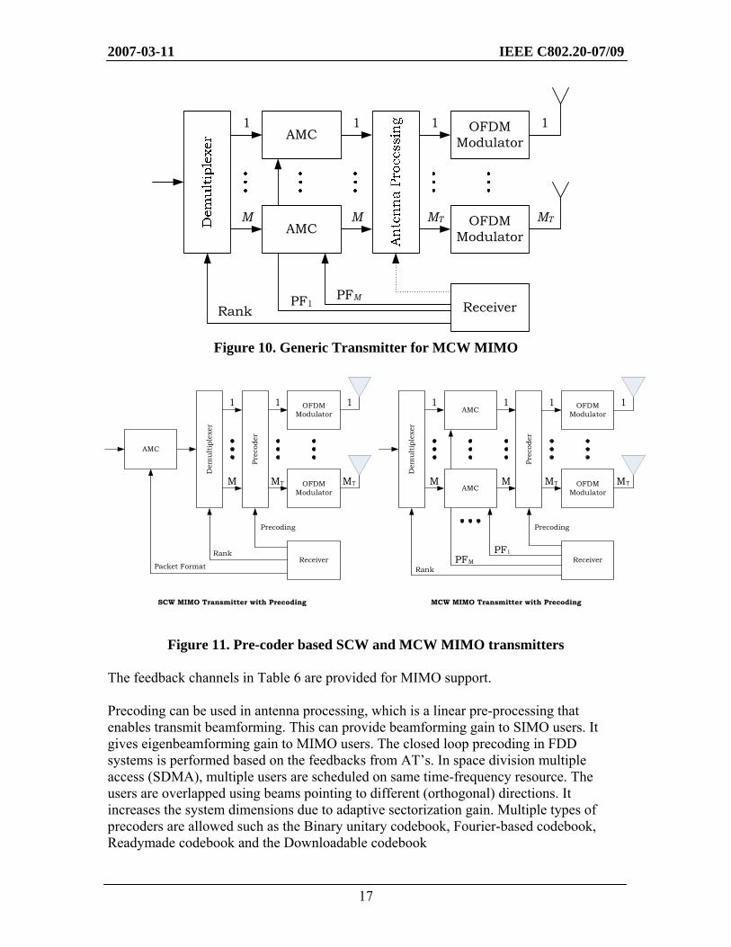
Figure 10. Generic Transmitter for MCW MIMO
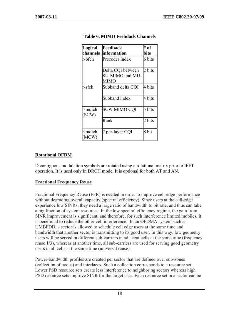
Figure 11. Pre-coder based SCW and MCW MIMO transmitters The feedback channels in Table 6 are provided for MIMO support. Precoding can be used in antenna processing, which is a linear pre-processing that enables transmit beamforming. This can provide beamforming gain to SIMO users. It gives eigenbeamforming gain to MIMO users. The closed loop precoding in FDD systems is performed based on the feedbacks from AT’s. In space division multiple access (SDMA), multiple users are scheduled on same time-frequency resource. The users are overlapped using beams pointing to different (orthogonal) directions. It increases the system dimensions due to adaptive sectorization gain. Multiple types of precoders are allowed such as the Binary unitary codebook, Fourier-based codebook, Readymade codebook and the Downloadable codebook
AMC OFDM Modulator
OFDM Modulator
ReceiverRank
1
MT
1
M
1
MTAMC
1
M
PF1PFM
Receiver
OFDMModulator
OFDMModulator
AMC
AMC
Precoding
Dem
ult
iple
xer
Prec
oder
TM
1PFMPF
M
1
M TM
1 1 1
RankReceiver
OFDMModulator
OFDMModulator
AMC
Precoding
Prec
oder
TMM TM
1 1 1
Rank
Dem
ult
iple
xer
Packet Format
SCW MIMO Transmitter with Precoding MCW MIMO Transmitter with Precoding
2007-03-11 IEEE C802.20-07/09
18
Table 6. MIMO Feebdack Channels
Logical channels
Feedback information
# of bits
Precoder index 6 bits r-bfch
Delta CQI between SU-MIMO and MU-MIMO
2 bits
Subband delta CQI 4 bits r-sfch
Subband index 4 bits
SCW MIMO CQI 5 bits r-mqich (SCW)
Rank 2 bits
r-mqich (MCW)
2 per-layer CQI 8 bit
Rotational OFDM D contiguous modulation symbols are rotated using a rotational matrix prior to IFFT operation. It is used only in DRCH mode. It is optional for both AT and AN. Fractional Frequency Reuse Fractional Frequency Reuse (FFR) is needed in order to improve cell-edge performance without degrading overall capacity (spectral efficiency). Since users at the cell-edge experience low SINRs, they need a large ratio of bandwidth to bit rate, and thus can take a big fraction of system resources. In the low spectral efficiency regime, the gain from SINR improvement is significant, and therefore, for such interference limited mobiles, it is beneficial to reduce the other-cell interference. In an OFDMA system such as UMBFDD, a sector is allowed to schedule cell edge users at the same time and bandwidth that another sector is transmitting to its good user. In this way, low geometry users will be served in different sub-carriers in adjacent cells at the same time (frequency reuse 1/3), whereas at another time, all sub-carriers are used for serving good geometry users in all cells at the same time (universal reuse). Power-bandwidth profiles are created per sector that are defined over sub-zones (collection of nodes) and interlaces. Such a collection corresponds to a resource set. Lower PSD resource sets create less interference to neighboring sectors whereas high PSD resource sets improve SINR for the target user. Each resource set in a sector can be
2007-03-11 IEEE C802.20-07/09
19
allocated a PSD corresponding to the geometry of the users that should be scheduled by that sector over that resource set. By portioning the resource sets across sectors in this manner, one can make sure that each geometry-class of user, due to interference avoidance gain, is able to experience the desired SINR. The users report a regular wide-band CQI, and a sub-band CQI. Further, long-term interference differences, referred to as VCQI, seen over the different resource sets are also signaled at a slower rate (L3 signaling). This enables the scheduler to have full knowledge of the users’ SINRs in order to take the scheduling decisions. BCMCS: Broadcast and Supercast The system supports broadcast services using a single frequency network (SFN) transmission. Broadcast sub-bands are defined to be a set of 128 contiguous tones over one interlace. At least one sub-band on each interlace is not assigned for BCMCS transmission in order to carry control signaling to support the reverse link. Unicast transmission hopping avoids the sub-bands given to BCMCS. There are two numerologies for BCMCS, with each deployment uses one format only. These numerologies trade-off overhead, operation at high speeds, and delay spreads (up to 40 μs for repeater). For both numerologies, BCMCS frames line up with the PHY Frames for regular unicast transmission. The coding and modulation used are • Inner rate 1/5 turbo code, same as in unicast design • Outer Reed-Solomon code to collect time-diversity • Support hierarchical modulation for different data rates depending on SNR • Two layers of transmission: base layer and enhancement layer The packet formats defined support QPSK, 16QAM, 64QAM with modulation step-down. Variable rate transmission in time domain as well as frequency domain is supported for zone-based BCMCS. This gives a transition from SFN-specific OFDM numerology to unicast OFDM numerology during the transmission of a given packet. Further, a logical channel at the enhanced layer can be superposed on a logical channel at the base layer to result in hierarchical modulation that users in better conditions can demodulate, in order to get better quality. Further, there is support for Supercast, wherein broadcast transmissions are overlapped with unicast transmissions (to good users) in the same time/frequency resources. The power-split between broadcast and unicast is sector-specific and interlace, and re-transmission number specific. This gives rise to various degrees of SFN operation. The unicast users that are scheduled on top of the broadcast layer decode the BCMCS signal first, and then decode the unicast signal after interference cancellation.
2007-03-11 IEEE C802.20-07/09
20
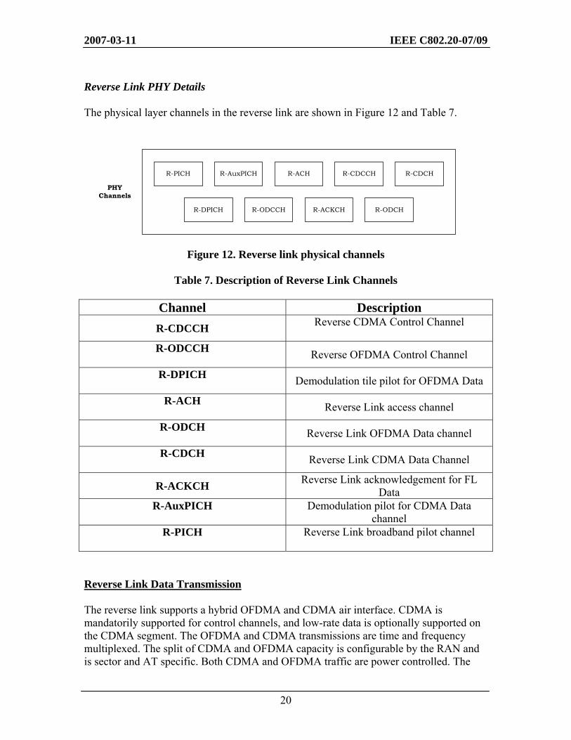
Reverse Link PHY Details The physical layer channels in the reverse link are shown in Figure 12 and Table 7.
Figure 12. Reverse link physical channels
Table 7. Description of Reverse Link Channels
Channel Description R-CDCCH Reverse CDMA Control Channel
R-ODCCH
Reverse OFDMA Control Channel
R-DPICH Demodulation tile pilot for OFDMA Data
R-ACH Reverse Link access channel
R-ODCH Reverse Link OFDMA Data channel
R-CDCH Reverse Link CDMA Data Channel
R-ACKCH Reverse Link acknowledgement for FL Data
R-AuxPICH
Demodulation pilot for CDMA Data channel
R-PICH
Reverse Link broadband pilot channel
Reverse Link Data Transmission The reverse link supports a hybrid OFDMA and CDMA air interface. CDMA is mandatorily supported for control channels, and low-rate data is optionally supported on the CDMA segment. The OFDMA and CDMA transmissions are time and frequency multiplexed. The split of CDMA and OFDMA capacity is configurable by the RAN and is sector and AT specific. Both CDMA and OFDMA traffic are power controlled. The
PHYChannels
R-PICH R-AuxPICH R-ACH R-CDCCH R-CDCH
R-DPICH R-ODCCH R-ACKCH R-ODCH
2007-03-11 IEEE C802.20-07/09
21
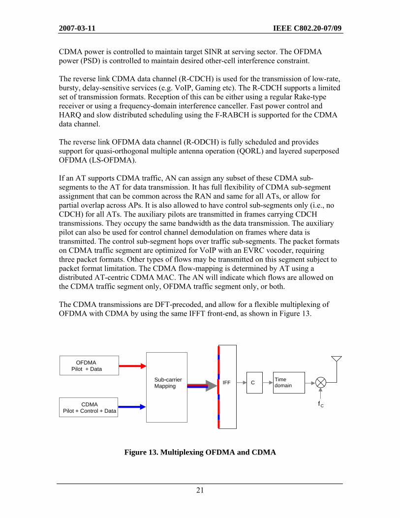
CDMA power is controlled to maintain target SINR at serving sector. The OFDMA power (PSD) is controlled to maintain desired other-cell interference constraint. The reverse link CDMA data channel (R-CDCH) is used for the transmission of low-rate, bursty, delay-sensitive services (e.g. VoIP, Gaming etc). The R-CDCH supports a limited set of transmission formats. Reception of this can be either using a regular Rake-type receiver or using a frequency-domain interference canceller. Fast power control and HARQ and slow distributed scheduling using the F-RABCH is supported for the CDMA data channel. The reverse link OFDMA data channel (R-ODCH) is fully scheduled and provides support for quasi-orthogonal multiple antenna operation (QORL) and layered superposed OFDMA (LS-OFDMA). If an AT supports CDMA traffic, AN can assign any subset of these CDMA sub-segments to the AT for data transmission. It has full flexibility of CDMA sub-segment assignment that can be common across the RAN and same for all ATs, or allow for partial overlap across APs. It is also allowed to have control sub-segments only (i.e., no CDCH) for all ATs. The auxiliary pilots are transmitted in frames carrying CDCH transmissions. They occupy the same bandwidth as the data transmission. The auxiliary pilot can also be used for control channel demodulation on frames where data is transmitted. The control sub-segment hops over traffic sub-segments. The packet formats on CDMA traffic segment are optimized for VoIP with an EVRC vocoder, requiring three packet formats. Other types of flows may be transmitted on this segment subject to packet format limitation. The CDMA flow-mapping is determined by AT using a distributed AT-centric CDMA MAC. The AN will indicate which flows are allowed on the CDMA traffic segment only, OFDMA traffic segment only, or both. The CDMA transmissions are DFT-precoded, and allow for a flexible multiplexing of OFDMA with CDMA by using the same IFFT front-end, as shown in Figure 13.
Figure 13. Multiplexing OFDMA and CDMA
Sub-carrier Mapping
- C Time domain
fC
IFF
CDMA Pilot + Control + Data
OFDMA Pilot + Data
2007-03-11 IEEE C802.20-07/09
22
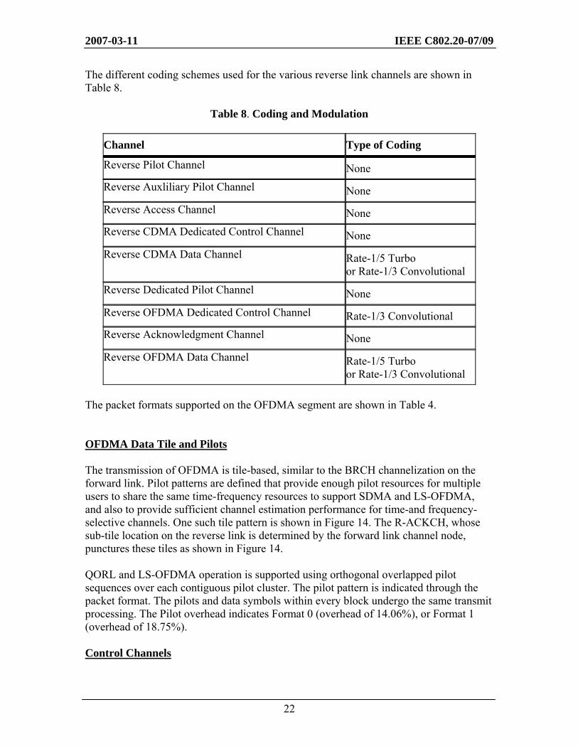
The different coding schemes used for the various reverse link channels are shown in Table 8.
Table 8. Coding and Modulation
Channel Type of Coding
Reverse Pilot Channel None Reverse Auxliliary Pilot Channel None Reverse Access Channel None Reverse CDMA Dedicated Control Channel None Reverse CDMA Data Channel Rate-1/5 Turbo
or Rate-1/3 Convolutional Reverse Dedicated Pilot Channel None Reverse OFDMA Dedicated Control Channel Rate-1/3 Convolutional Reverse Acknowledgment Channel None Reverse OFDMA Data Channel Rate-1/5 Turbo
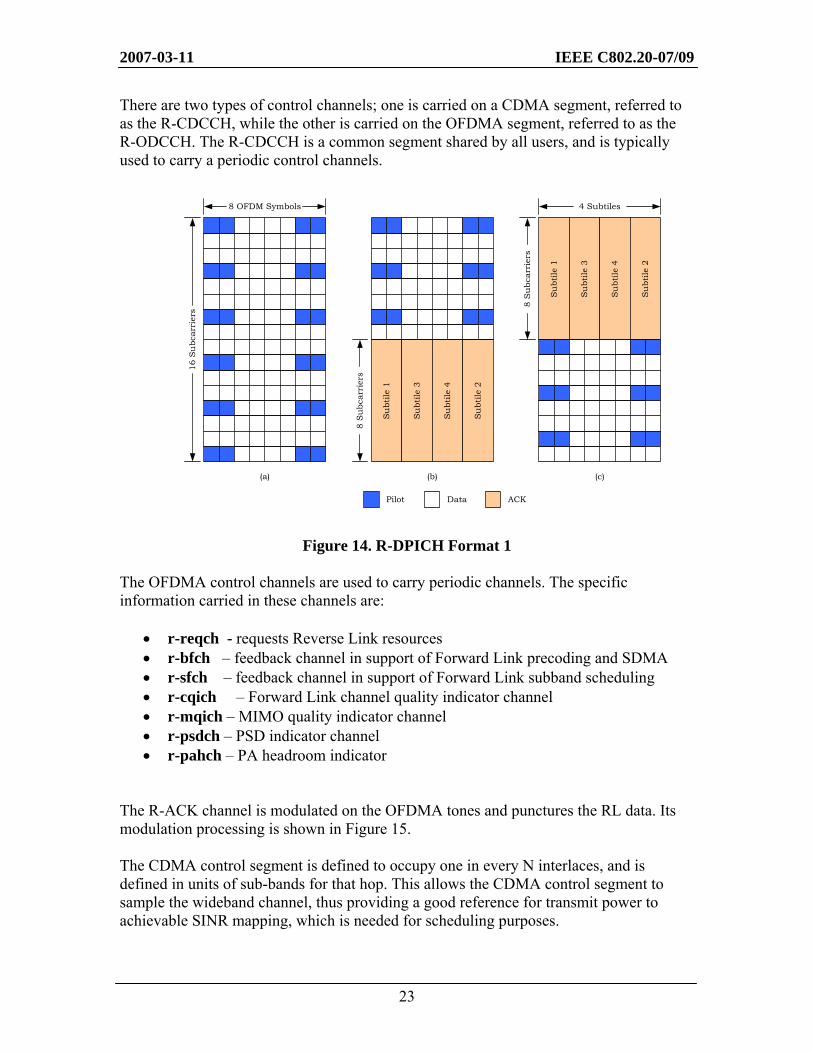
or Rate-1/3 Convolutional The packet formats supported on the OFDMA segment are shown in Table 4. OFDMA Data Tile and Pilots The transmission of OFDMA is tile-based, similar to the BRCH channelization on the forward link. Pilot patterns are defined that provide enough pilot resources for multiple users to share the same time-frequency resources to support SDMA and LS-OFDMA, and also to provide sufficient channel estimation performance for time-and frequency-selective channels. One such tile pattern is shown in Figure 14. The R-ACKCH, whose sub-tile location on the reverse link is determined by the forward link channel node, punctures these tiles as shown in Figure 14. QORL and LS-OFDMA operation is supported using orthogonal overlapped pilot sequences over each contiguous pilot cluster. The pilot pattern is indicated through the packet format. The pilots and data symbols within every block undergo the same transmit processing. The Pilot overhead indicates Format 0 (overhead of 14.06%), or Format 1 (overhead of 18.75%). Control Channels
2007-03-11 IEEE C802.20-07/09
23
There are two types of control channels; one is carried on a CDMA segment, referred to as the R-CDCCH, while the other is carried on the OFDMA segment, referred to as the R-ODCCH. The R-CDCCH is a common segment shared by all users, and is typically used to carry a periodic control channels.
Figure 14. R-DPICH Format 1 The OFDMA control channels are used to carry periodic channels. The specific information carried in these channels are:
• r-reqch - requests Reverse Link resources • r-bfch – feedback channel in support of Forward Link precoding and SDMA • r-sfch – feedback channel in support of Forward Link subband scheduling • r-cqich – Forward Link channel quality indicator channel • r-mqich – MIMO quality indicator channel • r-psdch – PSD indicator channel • r-pahch – PA headroom indicator
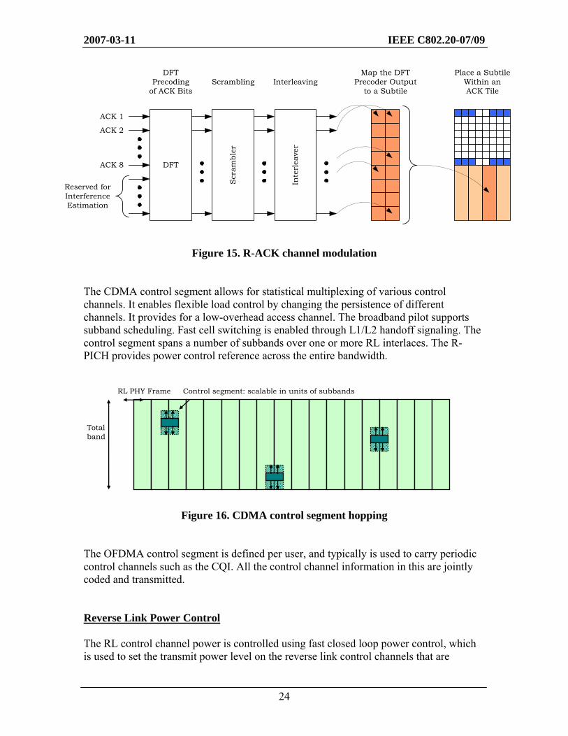
The R-ACK channel is modulated on the OFDMA tones and punctures the RL data. Its modulation processing is shown in Figure 15. The CDMA control segment is defined to occupy one in every N interlaces, and is defined in units of sub-bands for that hop. This allows the CDMA control segment to sample the wideband channel, thus providing a good reference for transmit power to achievable SINR mapping, which is needed for scheduling purposes.
Su
btile
1
Su
btile
3
Su
btile
4
Su
btile
2
4 Subtiles
8 S
ubc
arri
ers
(c)
8 OFDM Symbols
16 S
ubc
arri
ers
(a)
Su
btile
1
Su
btile
3
Su
btile
4
Su
btile
2
8 S
ubc
arri
ers
(b)
Pilot Data ACK
2007-03-11 IEEE C802.20-07/09
24
Figure 15. R-ACK channel modulation The CDMA control segment allows for statistical multiplexing of various control channels. It enables flexible load control by changing the persistence of different channels. It provides for a low-overhead access channel. The broadband pilot supports subband scheduling. Fast cell switching is enabled through L1/L2 handoff signaling. The control segment spans a number of subbands over one or more RL interlaces. The R-PICH provides power control reference across the entire bandwidth.
Figure 16. CDMA control segment hopping
The OFDMA control segment is defined per user, and typically is used to carry periodic control channels such as the CQI. All the control channel information in this are jointly coded and transmitted. Reverse Link Power Control The RL control channel power is controlled using fast closed loop power control, which is used to set the transmit power level on the reverse link control channels that are
RL PHY Frame
Total band
Control segment: scalable in units of subbands
DFTPrecoding
of ACK BitsScrambling
Map the DFT Precoder Output
to a Subtile
Inte
rlea
ver
DFTACK 8
ACK 1
ACK 2
Scr
ambl
er
Reserved forInterferenceEstimation
InterleavingPlace a Subtile
Within anACK Tile
2007-03-11 IEEE C802.20-07/09
25
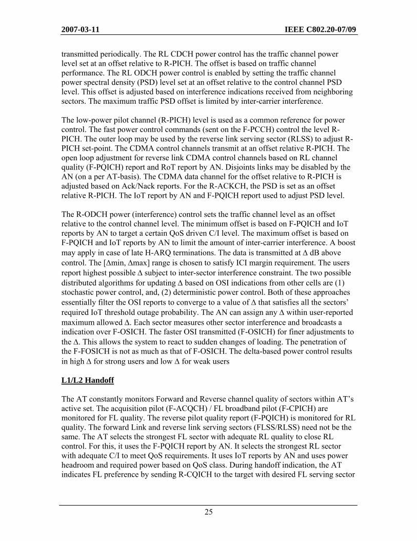
transmitted periodically. The RL CDCH power control has the traffic channel power level set at an offset relative to R-PICH. The offset is based on traffic channel performance. The RL ODCH power control is enabled by setting the traffic channel power spectral density (PSD) level set at an offset relative to the control channel PSD level. This offset is adjusted based on interference indications received from neighboring sectors. The maximum traffic PSD offset is limited by inter-carrier interference. The low-power pilot channel (R-PICH) level is used as a common reference for power control. The fast power control commands (sent on the F-PCCH) control the level R-PICH. The outer loop may be used by the reverse link serving sector (RLSS) to adjust R-PICH set-point. The CDMA control channels transmit at an offset relative R-PICH. The open loop adjustment for reverse link CDMA control channels based on RL channel quality (F-PQICH) report and RoT report by AN. Disjoints links may be disabled by the AN (on a per AT-basis). The CDMA data channel for the offset relative to R-PICH is adjusted based on Ack/Nack reports. For the R-ACKCH, the PSD is set as an offset relative R-PICH. The IoT report by AN and F-PQICH report used to adjust PSD level. The R-ODCH power (interference) control sets the traffic channel level as an offset relative to the control channel level. The minimum offset is based on F-PQICH and IoT reports by AN to target a certain QoS driven C/I level. The maximum offset is based on F-PQICH and IoT reports by AN to limit the amount of inter-carrier interference. A boost may apply in case of late H-ARQ terminations. The data is transmitted at Δ dB above control. The [Δmin, Δmax] range is chosen to satisfy ICI margin requirement. The users report highest possible Δ subject to inter-sector interference constraint. The two possible distributed algorithms for updating Δ based on OSI indications from other cells are (1) stochastic power control, and, (2) deterministic power control. Both of these approaches essentially filter the OSI reports to converge to a value of Δ that satisfies all the sectors’ required IoT threshold outage probability. The AN can assign any Δ within user-reported maximum allowed Δ. Each sector measures other sector interference and broadcasts a indication over F-OSICH. The faster OSI transmitted (F-OSICH) for finer adjustments to the Δ. This allows the system to react to sudden changes of loading. The penetration of the F-FOSICH is not as much as that of F-OSICH. The delta-based power control results in high Δ for strong users and low Δ for weak users L1/L2 Handoff The AT constantly monitors Forward and Reverse channel quality of sectors within AT’s active set. The acquisition pilot (F-ACQCH) / FL broadband pilot (F-CPICH) are monitored for FL quality. The reverse pilot quality report (F-PQICH) is monitored for RL quality. The forward Link and reverse link serving sectors (FLSS/RLSS) need not be the same. The AT selects the strongest FL sector with adequate RL quality to close RL control. For this, it uses the F-PQICH report by AN. It selects the strongest RL sector with adequate C/I to meet QoS requirements. It uses IoT reports by AN and uses power headroom and required power based on QoS class. During handoff indication, the AT indicates FL preference by sending R-CQICH to the target with desired FL serving sector
2007-03-11 IEEE C802.20-07/09
26
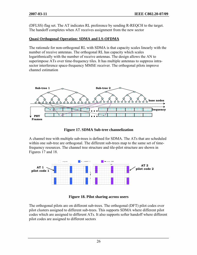
(DFLSS) flag set. The AT indicates RL preference by sending R-REQCH to the target. The handoff completes when AT receives assignment from the new sector Quasi Orthogonal Operation: SDMA and LS-OFDMA The rationale for non-orthogonal RL with SDMA is that capacity scales linearly with the number of receive antennas. The orthogonal RL has capacity which scales logarithmically with the number of receive antennas. The design allows the AN to superimpose ATs over time-frequency tiles. It has multiple antennas to suppress intra-sector interference space-frequency MMSE receiver. The orthogonal pilots improve channel estimation
Figure 17. SDMA Sub-tree channelization A channel tree with multiple sub-trees is defined for SDMA. The ATs that are scheduled within one sub-tree are orthogonal. The different sub-trees map to the same set of time-frequency resources. The channel tree structure and tile-pilot structure are shown in Figures 17 and 18.
Figure 18. Pilot sharing across users The orthogonal pilots are on different sub-trees. The orthogonal (DFT) pilot codes over pilot clusters assigned to different sub-trees. This supports SDMA where different pilot codes which are assigned to different ATs. It also supports softer handoff where different pilot codes are assigned to different sectors
Sub-tree 1 Sub-tree 2
base nodes
frequency
PHY Frames
AT 1 pilot code 1
AT 2 pilot code 2
2007-03-11 IEEE C802.20-07/09
27
Layer Superposed (LS) OFDMA is another approach for non-orthogonal transmissions within OFDMA that does not rely on multiple antennas to suppress interference. LS-OFDMA allows for overloading of OFDMA resources by letting users overlap in time/frequency. The users’ signals are separated by interference cancellation/joint decoding. The key idea is to “layer” users according to achievable spectral efficiency. The overloading is possible per spatial dimension and thus can even be used without multiple antenna receivers. Users with similar spectral efficiency are made orthogonal and are transmitted within a layer, which achieves intra-layer fairness as in a conventional OFDMA system with scheduling. Users in different layers interfere with each other and occupy overlapping bandwidth. Layers are separated with interference cancellation or joint decoding. The packet format and bandwidth to all users are explicitly allocated by the AN. The layers hop independently of each other. This is achieved by scheduling ATs of different layers on different sub-trees, which leads to better interference averaging. Subband hopping allows for joint hopping of large assignments and enables joint decoding. The first layer is most aggressive and has higher modulation and code-rates and possibly earlier HARQ termination targets. It attempts to first decode all first layer users by canceling those that succeed and then proceeds to the next layer. The channel estimation is performed for up to first 3 layers of users based on orthogonal pilot resources. Pilot cancellation is performed based on these estimates, and channel estimation is done for the other layers post pilot interference cancellation. The number of non-orthogonal layers will be dynamically determined by AP.
The MAC Layer
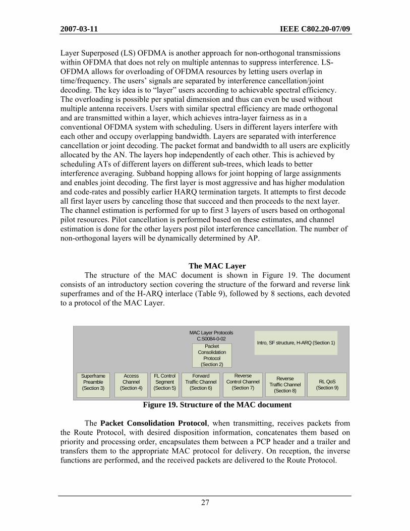
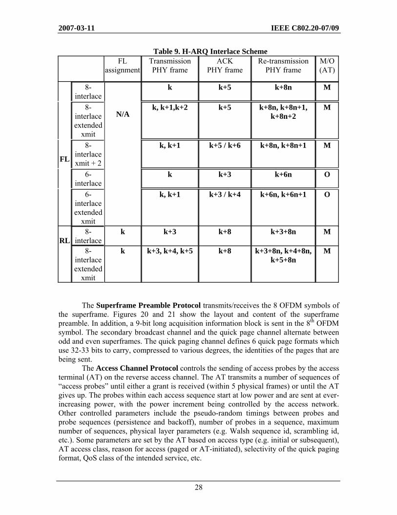
The structure of the MAC document is shown in Figure 19. The document consists of an introductory section covering the structure of the forward and reverse link superframes and of the H-ARQ interlace (Table 9), followed by 8 sections, each devoted to a protocol of the MAC Layer.
Figure 19. Structure of the MAC document The Packet Consolidation Protocol, when transmitting, receives packets from
the Route Protocol, with desired disposition information, concatenates them based on priority and processing order, encapsulates them between a PCP header and a trailer and transfers them to the appropriate MAC protocol for delivery. On reception, the inverse functions are performed, and the received packets are delivered to the Route Protocol.
MAC Layer ProtocolsC.S0084-0-02
Access Channel
(Section 4)
FL Control Segment
(Section 5)
ForwardTraffic Channel
(Section 6)
ReverseControl Channel
(Section 7)
ReverseTraffic Channel
(Section 8)
RL QoS (Section 9)
Packet Consolidation
Protocol(Section 2)
Superframe Preamble (Section 3)
Intro, SF structure, H-ARQ (Section 1)
2007-03-11 IEEE C802.20-07/09
28
Table 9. H-ARQ Interlace Scheme FL
assignment Transmission PHY frame
ACK PHY frame
Re-transmission PHY frame
M/O (AT)
8-interlace
k k+5 k+8n M
8-interlace extended
xmit
k, k+1,k+2 k+5 k+8n, k+8n+1, k+8n+2
M
8-interlace xmit + 2
k, k+1 k+5 / k+6 k+8n, k+8n+1 M
6-interlace
k k+3 k+6n O
FL
6-interlace extended
xmit
N/A
k, k+1 k+3 / k+4 k+6n, k+6n+1 O
8-interlace
k k+3 k+8 k+3+8n M RL
8-interlace extended
xmit
k k+3, k+4, k+5 k+8 k+3+8n, k+4+8n, k+5+8n
M
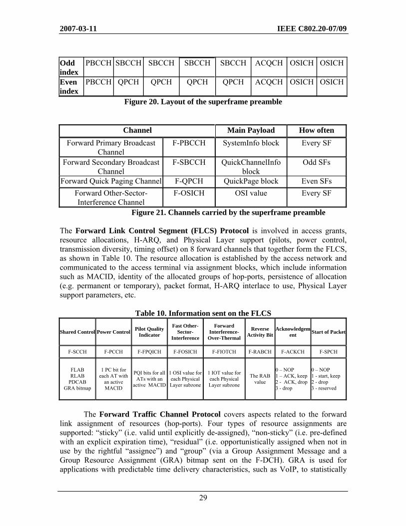
The Superframe Preamble Protocol transmits/receives the 8 OFDM symbols of the superframe. Figures 20 and 21 show the layout and content of the superframe preamble. In addition, a 9-bit long acquisition information block is sent in the 8th OFDM symbol. The secondary broadcast channel and the quick page channel alternate between odd and even superframes. The quick paging channel defines 6 quick page formats which use 32-33 bits to carry, compressed to various degrees, the identities of the pages that are being sent.
The Access Channel Protocol controls the sending of access probes by the access terminal (AT) on the reverse access channel. The AT transmits a number of sequences of “access probes” until either a grant is received (within 5 physical frames) or until the AT gives up. The probes within each access sequence start at low power and are sent at ever-increasing power, with the power increment being controlled by the access network. Other controlled parameters include the pseudo-random timings between probes and probe sequences (persistence and backoff), number of probes in a sequence, maximum number of sequences, physical layer parameters (e.g. Walsh sequence id, scrambling id, etc.). Some parameters are set by the AT based on access type (e.g. initial or subsequent), AT access class, reason for access (paged or AT-initiated), selectivity of the quick paging format, QoS class of the intended service, etc.
2007-03-11 IEEE C802.20-07/09
29
Odd index
PBCCH SBCCH SBCCH SBCCH SBCCH ACQCH OSICH OSICH
Even index
PBCCH QPCH QPCH QPCH QPCH ACQCH OSICH OSICH
Figure 20. Layout of the superframe preamble
Channel Main Payload How often Forward Primary Broadcast
Channel F-PBCCH SystemInfo block Every SF
Forward Secondary Broadcast Channel
F-SBCCH QuickChannelInfo block
Odd SFs
Forward Quick Paging Channel F-QPCH QuickPage block Even SFs Forward Other-Sector-Interference Channel
F-OSICH OSI value Every SF
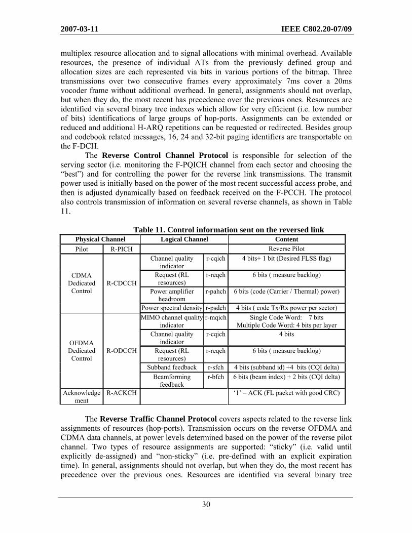
Figure 21. Channels carried by the superframe preamble The Forward Link Control Segment (FLCS) Protocol is involved in access grants, resource allocations, H-ARQ, and Physical Layer support (pilots, power control, transmission diversity, timing offset) on 8 forward channels that together form the FLCS, as shown in Table 10. The resource allocation is established by the access network and communicated to the access terminal via assignment blocks, which include information such as MACID, identity of the allocated groups of hop-ports, persistence of allocation (e.g. permanent or temporary), packet format, H-ARQ interlace to use, Physical Layer support parameters, etc.
Table 10. Information sent on the FLCS
Shared Control Power Control Pilot Quality Indicator
Fast Other-Sector-
Interference
Forward Interference-
Over-Thermal
Reverse Activity Bit
Acknowledgement Start of Packet
F-SCCH F-PCCH F-FPQICH F-FOSICH F-FIOTCH F-RABCH F-ACKCH F-SPCH
FLAB RLAB
PDCAB GRA bitmap
1 PC bit for each AT with
an active MACID
PQI bits for all ATs with an
active MACID
1 OSI value for each Physical Layer subzone
1 IOT value for each Physical Layer subzone
The RAB value
0 – NOP 1 – ACK, keep 2 - ACK, drop 3 - drop
0 – NOP 1 - start, keep 2 - drop 3 - reserved
The Forward Traffic Channel Protocol covers aspects related to the forward
link assignment of resources (hop-ports). Four types of resource assignments are supported: “sticky” (i.e. valid until explicitly de-assigned), “non-sticky” (i.e. pre-defined with an explicit expiration time), “residual” (i.e. opportunistically assigned when not in use by the rightful “assignee”) and “group” (via a Group Assignment Message and a Group Resource Assignment (GRA) bitmap sent on the F-DCH). GRA is used for applications with predictable time delivery characteristics, such as VoIP, to statistically
2007-03-11 IEEE C802.20-07/09
30
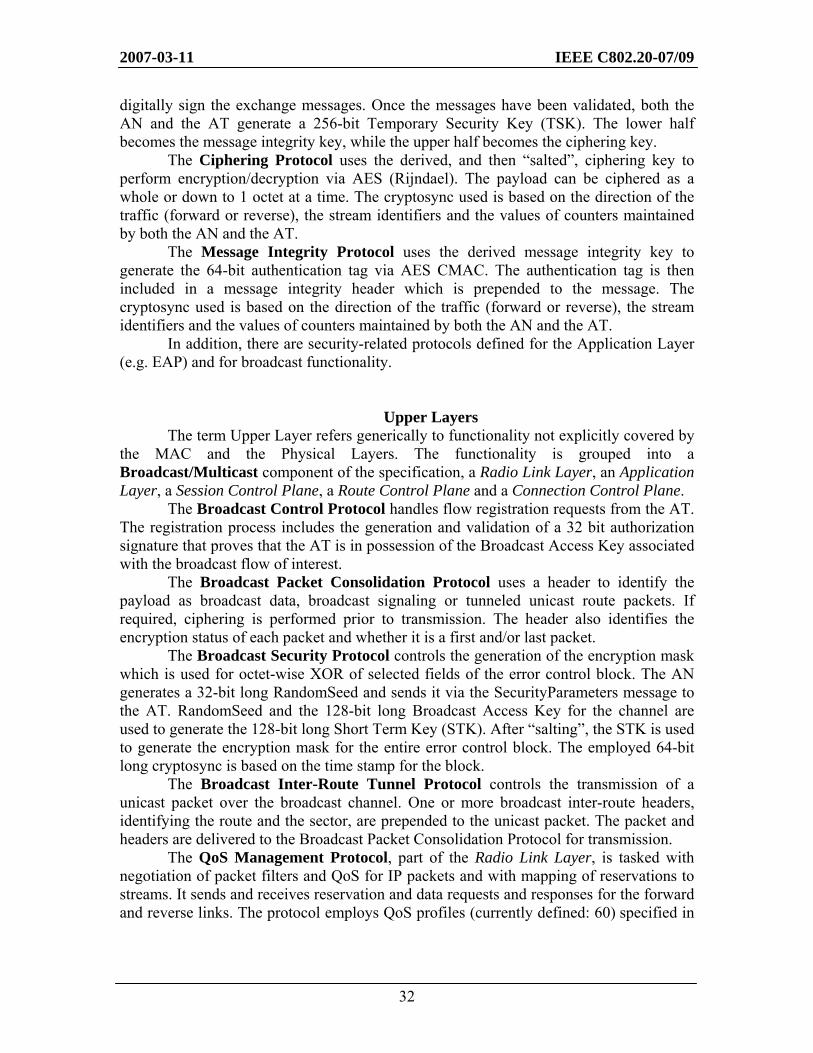
multiplex resource allocation and to signal allocations with minimal overhead. Available resources, the presence of individual ATs from the previously defined group and allocation sizes are each represented via bits in various portions of the bitmap. Three transmissions over two consecutive frames every approximately 7ms cover a 20ms vocoder frame without additional overhead. In general, assignments should not overlap, but when they do, the most recent has precedence over the previous ones. Resources are identified via several binary tree indexes which allow for very efficient (i.e. low number of bits) identifications of large groups of hop-ports. Assignments can be extended or reduced and additional H-ARQ repetitions can be requested or redirected. Besides group and codebook related messages, 16, 24 and 32-bit paging identifiers are transportable on the F-DCH. The Reverse Control Channel Protocol is responsible for selection of the serving sector (i.e. monitoring the F-PQICH channel from each sector and choosing the “best”) and for controlling the power for the reverse link transmissions. The transmit power used is initially based on the power of the most recent successful access probe, and then is adjusted dynamically based on feedback received on the F-PCCH. The protocol also controls transmission of information on several reverse channels, as shown in Table 11.
Table 11. Control information sent on the reversed link Physical Channel Logical Channel Content Pilot R-PICH Reverse Pilot
Channel quality indicator
r-cqich 4 bits+ 1 bit (Desired FLSS flag)
Request (RL resources)
r-reqch 6 bits ( measure backlog)
Power amplifier headroom
r-pahch 6 bits (code (Carrier / Thermal) power)
CDMA Dedicated Control
R-CDCCH
Power spectral density r-psdch 4 bits ( code Tx/Rx power per sector) MIMO channel quality
indicator r-mqich Single Code Word: 7 bits
Multiple Code Word: 4 bits per layer Channel quality
indicator r-cqich 4 bits
Request (RL resources)
r-reqch 6 bits ( measure backlog)
Subband feedback r-sfch 4 bits (subband id) +4 bits (CQI delta)
OFDMA Dedicated Control
R-ODCCH
Beamforming feedback
r-bfch 6 bits (beam index) + 2 bits (CQI delta)
Acknowledgement
R-ACKCH ‘1’ – ACK (FL packet with good CRC)
The Reverse Traffic Channel Protocol covers aspects related to the reverse link
assignments of resources (hop-ports). Transmission occurs on the reverse OFDMA and CDMA data channels, at power levels determined based on the power of the reverse pilot channel. Two types of resource assignments are supported: “sticky” (i.e. valid until explicitly de-assigned) and “non-sticky” (i.e. pre-defined with an explicit expiration time). In general, assignments should not overlap, but when they do, the most recent has precedence over the previous ones. Resources are identified via several binary tree
2007-03-11 IEEE C802.20-07/09
31
indexes which allow for very efficient (i.e. low number of bits) identifications of large groups of hop-ports. Assignments can be extended or reduced and additional H-ARQ repetitions can be requested or redirected. In addition some control information can be sent on the data channels “in band”, via 8-bit control blocks (e.g. power amplifier headroom, request for RL resources, C/I changes reports).
The Reverse Link QoS Protocol prescribes maintenance of two token buckets for each stream: one (‘hint”) used to assist the scheduler, the other (“max”) to enable traffic shaping (i.e. knowing when to declare overflow and begin dropping packets). The bucket sizes (containing the number of octets available for transmission) are incremented based on the arrival rate of the stream and decremented based on the number of actually transmitted packets. The inner workings of the scheduler are outside the standard, but the expectation is that the scheduling will reflect priority, age of the packet in the queue, the time limit for the packet age as well as the size of the token buckets.
Broadcast MAC protocols
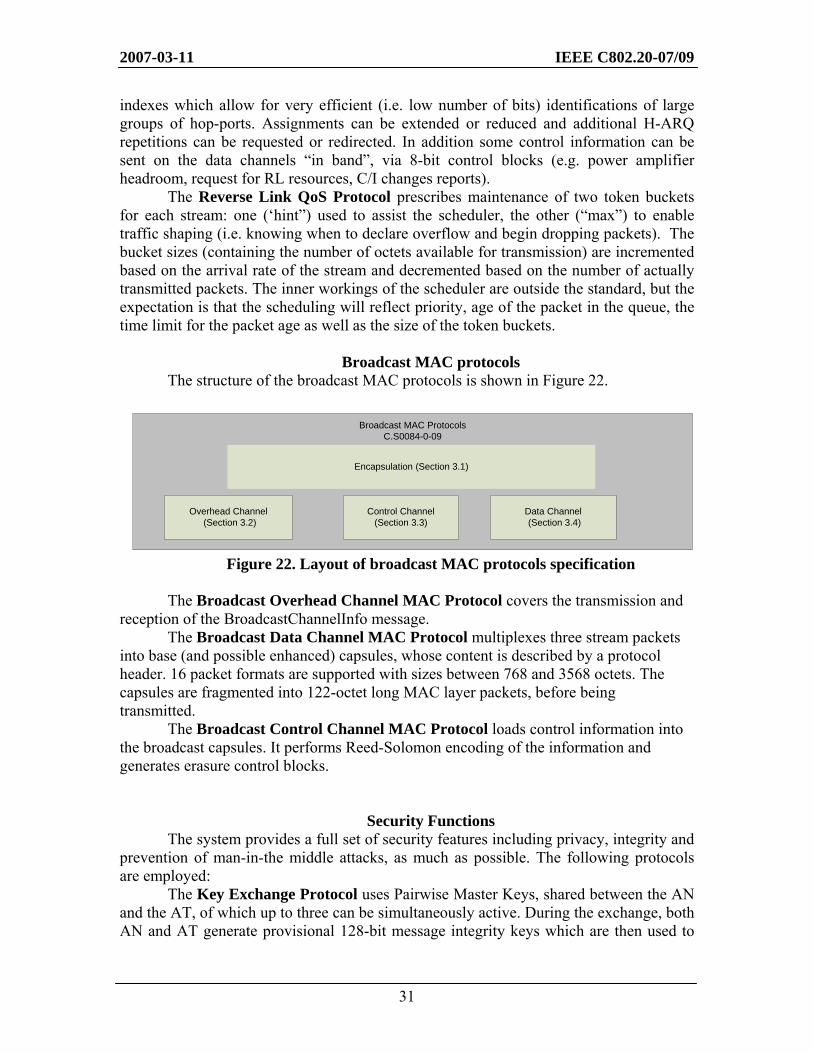
The structure of the broadcast MAC protocols is shown in Figure 22.
Figure 22. Layout of broadcast MAC protocols specification The Broadcast Overhead Channel MAC Protocol covers the transmission and
reception of the BroadcastChannelInfo message. The Broadcast Data Channel MAC Protocol multiplexes three stream packets
into base (and possible enhanced) capsules, whose content is described by a protocol header. 16 packet formats are supported with sizes between 768 and 3568 octets. The capsules are fragmented into 122-octet long MAC layer packets, before being transmitted.
The Broadcast Control Channel MAC Protocol loads control information into the broadcast capsules. It performs Reed-Solomon encoding of the information and generates erasure control blocks.
Security Functions The system provides a full set of security features including privacy, integrity and
prevention of man-in-the middle attacks, as much as possible. The following protocols are employed:
The Key Exchange Protocol uses Pairwise Master Keys, shared between the AN and the AT, of which up to three can be simultaneously active. During the exchange, both AN and AT generate provisional 128-bit message integrity keys which are then used to
Broadcast MAC ProtocolsC.S0084-0-09
Overhead Channel (Section 3.2)
Control Channel(Section 3.3)
Data Channel (Section 3.4)
Encapsulation (Section 3.1)
2007-03-11 IEEE C802.20-07/09
32
digitally sign the exchange messages. Once the messages have been validated, both the AN and the AT generate a 256-bit Temporary Security Key (TSK). The lower half becomes the message integrity key, while the upper half becomes the ciphering key.
The Ciphering Protocol uses the derived, and then “salted”, ciphering key to perform encryption/decryption via AES (Rijndael). The payload can be ciphered as a whole or down to 1 octet at a time. The cryptosync used is based on the direction of the traffic (forward or reverse), the stream identifiers and the values of counters maintained by both the AN and the AT.
The Message Integrity Protocol uses the derived message integrity key to generate the 64-bit authentication tag via AES CMAC. The authentication tag is then included in a message integrity header which is prepended to the message. The cryptosync used is based on the direction of the traffic (forward or reverse), the stream identifiers and the values of counters maintained by both the AN and the AT.
In addition, there are security-related protocols defined for the Application Layer (e.g. EAP) and for broadcast functionality.
Upper Layers
The term Upper Layer refers generically to functionality not explicitly covered by the MAC and the Physical Layers. The functionality is grouped into a Broadcast/Multicast component of the specification, a Radio Link Layer, an Application Layer, a Session Control Plane, a Route Control Plane and a Connection Control Plane. The Broadcast Control Protocol handles flow registration requests from the AT. The registration process includes the generation and validation of a 32 bit authorization signature that proves that the AT is in possession of the Broadcast Access Key associated with the broadcast flow of interest.
The Broadcast Packet Consolidation Protocol uses a header to identify the payload as broadcast data, broadcast signaling or tunneled unicast route packets. If required, ciphering is performed prior to transmission. The header also identifies the encryption status of each packet and whether it is a first and/or last packet.
The Broadcast Security Protocol controls the generation of the encryption mask which is used for octet-wise XOR of selected fields of the error control block. The AN generates a 32-bit long RandomSeed and sends it via the SecurityParameters message to the AT. RandomSeed and the 128-bit long Broadcast Access Key for the channel are used to generate the 128-bit long Short Term Key (STK). After “salting”, the STK is used to generate the encryption mask for the entire error control block. The employed 64-bit long cryptosync is based on the time stamp for the block.
The Broadcast Inter-Route Tunnel Protocol controls the transmission of a unicast packet over the broadcast channel. One or more broadcast inter-route headers, identifying the route and the sector, are prepended to the unicast packet. The packet and headers are delivered to the Broadcast Packet Consolidation Protocol for transmission.
The QoS Management Protocol, part of the Radio Link Layer, is tasked with negotiation of packet filters and QoS for IP packets and with mapping of reservations to streams. It sends and receives reservation and data requests and responses for the forward and reverse links. The protocol employs QoS profiles (currently defined: 60) specified in
2007-03-11 IEEE C802.20-07/09
33
3GPP2 C.R1001-F section 13 and QoS parameters (currently defined: 8) specified in 3GPP2 X.S0011-004-D Annex E.
The Radio Link Protocol, part of the Radio Link Layer, performs segmentation and reassembly of higher layer packets and performs Ack/Nak-based ARQ using a “sliding-window” algorithm. The protocol is parameterized and the parameters are negotiable. RLP invokes the message integrity functionality, fragments/reassembles the payload and ciphers it, and adds/removes the RLP header. The protocol is divided into a Segmentation and Reassembly Sub-Protocol and QuickNak Sub-protocol.
The Stream Protocol, part of the Radio Link Layer, prepends/removes a 5-bit header with the stream id to/from the RLP protocol data unit before delivering it down/up the protocol stack. 32 streams are defined, with some available for any use and some dedicated to broadcast/manycast (#0), best effort delivery signaling (#1), reliable delivery signaling (#2), reliable delivery inter-routing tunneling (#3) and best effort delivery inter-routing tunneling (#4-6).
The Route Protocol, part of the Radio Link Layer, decides whether to move the packet along on the local protocol stack for processing or to the Inter-Route Protocol for forwarding. The protocol prepends/removes the route protocol header (minimum length = 1 bit) to/from the Stream Protocol data unit. The header, if necessary, contains the id of the personality and the id of the AT (e.g. UATI).
The Signaling Protocol, part of the Application Layer, decides rules for “well-formed” messages: whole-octet length, transmission order (MSB first), non-ambiguous parsability, extension through addition only. The protocol provides the information required for delivery: forward/reverse/broadcast channel, delivery mode (e.g. Best Effort, Reliable), destination address. The protocol’s overhead is a 1-2 octet header which identifies the target protocol for the payload.
The Inter-Route Tunneling Protocol, part of the Application Layer, allows a currently serving node to act as packet relay for a previously serving node, without the need to transfer state information to the currently serving node. The protocol moves packets between a local or remote Route Protocol and the local RLP. The protocol overhead consists of one or more (RL manycast) headers which identify the target route, using remote route id, or Pilot PN or the access network identifier of the destination.
Other protocols referenced (i.e. not defined) in the Application Layer are the Extensible Authentication Protocol: EAP (IETF RFC 3748), Robust Header Compression: ROHC (IETF RFC 3095), Internet Protocol: IP (IETF RFC 791), etc.
The Session Management Protocol, part of the Session Control Plane, is activated by initial access, waits for the assignment of UATI and then activates the Session Configuration Protocol. The protocol maintains the “keep alive” functionality for the session and automatically closes dead sessions.
The Session Management Protocol, part of the Session Control Plane, negotiates protocols and attribute values for all the personalities (full configuration) or only for the InUse personality (fast configuration). Negotiation consists of the initiator (AN or AT) proposing a list of values, in descending order of preference, then the other party selecting the most desired acceptable value from the list. If no commonly acceptable value is found, then the protocol defined default value is used. The signaling provides full and flexible transaction oriented processing, including request/response, accept/reject, copy and reset functionality.
2007-03-11 IEEE C802.20-07/09
34
The Route Control Protocol, part of the Route Control Plane, activates and deactivates protocol stacks (routes) within an AN and AT, performs “keep-alive” functionality on each route and assigns and de-assigns UATI and Paging id to the AT. The protocol ensures the existence of a data attachment point route, a session anchor route, as well as the FL Serving route and the RL Serving route.
The Air Link Management Protocol, part of the Connection Control Plane, provides “umbrella” functionality that spawns other connection control protocols. It handles registration, the supported registration types being: zone-based, distance-based, network-code based, after loss of coverage and power-down. TuneAway scheduled intervals allow off-carrier activity. It also supports redirection to other carriers, if necessary.
The Initialization State Protocol, part of the Connection Control Plane, is instantiated only at the AT and covers the initial part of System Acquisition. The initial selection is based on information pre-stored in the AT or obtained during a prior redirect. The AT searches for pilot, decodes the superframe and enough overhead information to allow it to successfully be able to further decode the ExtendedChannelInfo message, which will complete the acquisition.
The Idle State Protocol, part of the Connection Control Plane, performs channel selection (for paging) by using a hash index to choose from the list of channels advertised in the SectorParameters message. The paging related functionality covers quick paging (on F-QPCH), full paging (on F-DCH), and fast re-paging (in case of erasure). To save battery the AT supports 3 levels of “sleep”, with increasingly spaced waking ups.
During the Connected State Protocol, part of the Connection Control Plane, the AT is assigned a MACID and becomes able to participate in data transfers. The protocol also supports a SemiConnected state, where the AT cannot use the RL channels, but can receive assignments on the Forward Shared Control Channel.
The Overhead Messages Protocol, part of the Connection Control Plane, sends the SystemInfo block on F-PBCCH every superframe and the QuickChannelInfo block over F-SBCCH every odd superframe. Periodically, it also sends the ExtendedChannelInfo and the SectorParameters messages. If the broadcast information changes, connected ATs will be sent the encapsulated version of those messages.
The Active Set Management Protocol, part of the Connection Control Plane, handles the three sets of pilots that are received by the AT: the Active set (pilots in use for traffic and control), the Candidate set (subject to reporting to the AN when the pilots become strong enough) and the Remaining set (all other pilots that can be monitored). Promoting/demoting pilots between those sets is based on absolute and relative power thresholds. Pilot reports are generated by AT autonomously or on demand from the AN. The AN synchronizes the Active set with the AT by sending the MACResourceAssignment message in reliable delivery mode.