RAAF Base Williams, Pt Cook – Stage 3 / 4 Remediation and ...
118
Commercial in Confidence RAAF Base Williams, Pt CookStage 3 / 4 Remediation and Validation Works Department of Defence 25 November 2010 RAAF Base Williams, Pt Cook – Stage 3 / 4 Remediation and Validation Works Remedial Action Plan
Transcript of RAAF Base Williams, Pt Cook – Stage 3 / 4 Remediation and ...

Commercial in Confidence
RAAF Base Williams, Pt CookStage 3 / 4 Remediation and Validation Works Department of Defence 25 November 2010
RAAF Base Williams, Pt Cook – Stage 3 / 4 Remediation and Validation Works
Remedial Action Plan

RAAF Base Williams, Pt CookStage 3 / 4 Remediation and Validation Works Remedial Action Plan
D1122709_RPT04_25Nov10 Revision 4 25/11/2010
AECOM
Remedial Action Plan
Prepared for
Department of Defence
Prepared by
AECOM Australia Pty Ltd Level 9, 8 Exhibition Street, Melbourne VIC 3000 T +61 3 9653 1234 F +61 3 9654 7117 www.aecom.com ABN 20 093 846 925
25 November 2010
60146508
© AECOM * AECOM Australia Pty Ltd (AECOM) has prepared this document for the purpose which is described in the Introduction
section, and was based on information provided by the client, AECOM's understanding of the site conditions, and AECOM's experience, having regard to the assumptions that AECOM can reasonably be expected to make in accordance with sound professional principles.
* This document was prepared for the sole use of the party identified on the cover sheet, and that party is the only intended beneficiary of AECOM's work.
* No other party should rely on the document without the prior written consent of AECOM, and AECOM undertakes no duty to, nor accepts any responsibility to, any third party who may rely upon this document.
* All rights reserved. No section or element of this document may be removed from this document, extracted, reproduced, electronically stored or transmitted in any form without the prior written permission of AECOM.


RAAF Base Williams, Pt CookStage 3 / 4 Remediation and Validation Works Remedial Action Plan
D1122709_RPT04_25Nov10 Revision 4 25/11/2010
AECOM
“This page has been left blank intentionally”

RAAF Base Williams, Pt CookStage 3 / 4 Remediation and Validation Works Remedial Action Plan
D1122709_RPT04_25Nov10 Revision 4 25/11/2010 i
AECOM
Contents
1.0 Introduction ................................................................................................................................................ 1
1.1 General ..................................................................................................................................... 1
1.2 Objectives ................................................................................................................................. 1
1.3 Environmental Audit and Factors Driving Site Clean Up ........................................................... 1
1.3.1 Defence Contamination Risk Assessment Tool ....................................................... 1
1.3.2 Legislative Requirements ......................................................................................... 2
2.0 Background ................................................................................................................................................ 3
2.1 Site Description ......................................................................................................................... 3
2.2 Current Site Setting ................................................................................................................... 3
2.3 Site History ............................................................................................................................... 3
2.3.1 Primary Chemicals of Interest .................................................................................. 4
2.4 Previous Environmental Investigations ..................................................................................... 4
2.5 Contaminant Source and Discharge Zone Nomenclature ......................................................... 5
2.6 Current Monitoring Program ..................................................................................................... 6
2.7 Previous Remediation Activities ................................................................................................ 6
2.8 Data Gaps ................................................................................................................................. 6
3.0 Conceptual Site Model ............................................................................................................................... 7
3.1 Geology and Hydrogeology ...................................................................................................... 7
3.2 Groundwater Flow ..................................................................................................................... 8
3.3 Potential Contamination Sources .............................................................................................. 8
3.4 Potential Contaminants of Interest ............................................................................................ 8
3.5 Transport Mechanisms ............................................................................................................. 9
3.6 Receptors ................................................................................................................................. 9
3.6.1 Human Health Risk Assessment .............................................................................. 9
3.6.2 Ecological Risk Assessment .................................................................................... 9
4.0 Regulatory Framework & Clean Up Objectives for Remedial Works ....................................................... 11
4.1 Victorian Legislation ................................................................................................................ 11
4.1.1 State Environment Protection Policy (Prevention and Management of Contamination of Land) .......................................................................................... 11
4.1.2 State Environment Protection Policy (Groundwaters of Victoria) ........................... 11
4.1.3 Surface Water Protection Policy ............................................................................ 13
4.1.4 Land Protection Policy ........................................................................................... 14
4.2 Commonwealth Legislation ..................................................................................................... 15
4.2.1 EPBC Act ............................................................................................................... 15
4.2.2 NEPM ..................................................................................................................... 15
4.2.3 Contamination Risk Assessment Tool (CRAT) ...................................................... 16

RAAF Base Williams, Pt CookStage 3 / 4 Remediation and Validation Works Remedial Action Plan
D1122709_RPT04_25Nov10 Revision 4 25/11/2010 ii
AECOM
4.3 Summary of Clean-up Objectives ........................................................................................... 16
4.3.1 Risk Reduction ....................................................................................................... 16
4.3.2 Legislative Objectives ............................................................................................ 17
5.0 Risks to Beneficial Uses .......................................................................................................................... 19
5.1 Findings from Initial Environmental Review ............................................................................ 19
5.2 Human Health Risk Assessment............................................................................................. 21
5.3 Ecological Risk Assessment ................................................................................................... 22
5.4 Defence Contamination Risk Assessment Tool (CRAT) ......................................................... 22
5.4.1 Pre-remediation CRAT ........................................................................................... 23
5.4.2 Post-remediation CRAT ......................................................................................... 23
6.0 Remedial Actions Previously Undertaken ................................................................................................ 25
6.1 Aeration Delivery System (ADS) ............................................................................................. 25
6.2 Cut-off Wall Installation ........................................................................................................... 25
6.3 In situ Chemical Oxidation (ISCO) Field Trial ......................................................................... 26
6.4 Shoreline Regression Protection ............................................................................................ 26
7.0 Assessment of Remediation Technologies .............................................................................................. 27
7.1 Literature Review .................................................................................................................... 27
7.1.1 DNAPL Source Zones Remediation Technologies ................................................ 27
7.1.2 Dissolved Phase Groundwater Remediation Technologies ................................... 28
7.2 Basis for Technology Assessment .......................................................................................... 29
7.2.1 Practicability of Clean Up ....................................................................................... 29
7.3 Screening of Remediation Technologies ................................................................................ 30
7.3.1 Preferred DNAPL Remedial Technology Options .................................................. 31
7.3.2 Preferred Groundwater Remedial Technology Options ......................................... 31
7.3.3 Assessment Criteria Weighting Sensitivity Analysis ............................................... 32
7.3.4 Sensitivity Assessment DNAPL Remediation Technologies .................................. 33
7.3.5 Sensitivity Assessment Groundwater Remediation Technologies ......................... 33
7.4 Remedial Technology Options ................................................................................................ 34
7.5 Detailed Remediation Technology Assessment - Overview .................................................... 34
7.6 Detailed Remediation Technology Assessment - DNAPL Degradation / Removal ................. 35
7.6.1 Background to Thermal Treatment ........................................................................ 36
7.6.1.1 Thermal Conductive Heating (TCH) ...................................................... 36
7.6.1.2 Excavation and Ex Situ Thermal Desorption ......................................... 38
7.6.2 In Situ Chemical Oxidation ..................................................................................... 39
7.6.3 Electrical Resistive Heating .................................................................................... 40
7.6.4 In Situ Steam Stripping .......................................................................................... 40
7.6.5 Other technologies ................................................................................................. 40
7.6.6 DNAPL Technology Ranking Sensitivity ................................................................ 40

RAAF Base Williams, Pt CookStage 3 / 4 Remediation and Validation Works Remedial Action Plan
D1122709_RPT04_25Nov10 Revision 4 25/11/2010 iii
AECOM
7.6.7 Recommended Remedial Option for DNAPL treatment ......................................... 40
7.7 Detailed Remediation Technology Assessment - Dissolved Phase Plumes ........................... 41
7.7.1 Monitored Natural Attenuation ............................................................................... 41
7.7.2 Enhanced In Situ Bioremediation ........................................................................... 41
7.7.3 Physical Containment / Capping ............................................................................ 42
7.7.4 Recommended Remedial Option for Dissolved Phase Plumes ............................. 42
7.8 Stockpile Management ........................................................................................................... 43
7.9 Summary ................................................................................................................................ 43
7.9.1 Remediation Objectives ......................................................................................... 43
7.9.2 DNAPL Removal to the Extent Practical ................................................................ 44
7.9.3 Dissolved Phase Management .............................................................................. 45
7.10 Recommended Remediation Strategy .................................................................................... 47
7.10.1 DNAPL Removal to the Extent Practical ................................................................ 47
7.10.2 Dissolved Phase Management .............................................................................. 47
7.10.3 Stockpile Management........................................................................................... 47
7.10.4 Contingency Measures to be Considered .............................................................. 48
7.10.4.1 Excavation and ex situ thermal desorption ............................................ 48
7.10.4.2 Dissolved Phase Management .............................................................. 49
8.0 Remediation Implementation ................................................................................................................... 51
8.1 General Works Program Overview ......................................................................................... 51
8.1.1 DNAPL Removal to the Extent Practical ................................................................ 51
8.1.2 Dissolved Phase Management .............................................................................. 52
8.1.3 Stockpile Management........................................................................................... 52
8.1.4 Validate Remediation Works .................................................................................. 52
8.2 Remediation Timeframes ........................................................................................................ 52
8.3 General Operational Details .................................................................................................... 53
8.3.1 Working Hours ....................................................................................................... 53
8.3.2 Site Facilities .......................................................................................................... 53
8.3.3 Site Layout ............................................................................................................. 53
8.3.4 Existing Structures ................................................................................................. 53
9.0 Remediation Work Procedures and Documentation ................................................................................ 55
9.1 DNAPL Removal ..................................................................................................................... 55
9.1.1 General strategy .................................................................................................... 55
9.1.2 Labour and equipment ........................................................................................... 55
9.1.3 Staging ................................................................................................................... 55
9.1.4 Validation ............................................................................................................... 56
9.1.5 Contingencies ........................................................................................................ 56
9.2 Monitored Natural Attenuation ................................................................................................ 57

RAAF Base Williams, Pt CookStage 3 / 4 Remediation and Validation Works Remedial Action Plan
D1122709_RPT04_25Nov10 Revision 4 25/11/2010 iv
AECOM
9.2.1 General strategy .................................................................................................... 57
9.2.2 Labour and equipment ........................................................................................... 57
9.2.3 Staging ................................................................................................................... 57
9.2.4 Validation ............................................................................................................... 57
9.2.5 Contingencies ........................................................................................................ 58
9.3 Surface and Wastewater Management ................................................................................... 58
9.3.1 Surface Water Management from Undisturbed Areas ........................................... 58
9.3.2 Surface Water Management from Disturbed Areas ............................................... 58
9.3.3 Sediment and Erosion Control ............................................................................... 58
9.4 Materials Handling and Management ..................................................................................... 58
9.4.1 Materials Tracking .................................................................................................. 59
9.4.2 Backfilling and Compaction .................................................................................... 59
9.4.3 Demolition Rubble and Waste ................................................................................ 60
9.4.4 Off-Site Waste Disposal ......................................................................................... 60
9.4.5 Dangerous Goods .................................................................................................. 60
9.5 Quality Assurance / Quality Control ........................................................................................ 60
9.5.1 Field QA/QC ........................................................................................................... 60
9.5.2 Field Duplicates ..................................................................................................... 61
9.5.3 Laboratory QA/QC ................................................................................................. 61
9.5.4 Record Keeping ..................................................................................................... 62
9.6 Occupational Health and Safety Procedures .......................................................................... 62
9.7 Work Plans ............................................................................................................................. 62
9.8 Remediation Safety and Environmental Management Plan .................................................... 63
9.9 Post-Remediation Site Management Plan (SMP) ................................................................... 63
9.10 Groundwater Quality Management Plan ................................................................................. 64
9.11 Remediation Schedule ............................................................................................................ 64
9.12 Annual Reporting .................................................................................................................... 64
10.0 Environmental Management .................................................................................................................... 67
10.1 Overview ................................................................................................................................. 67
10.2 Discussion of Selected Emissions and Discharges................................................................. 67
10.2.1 Dust........................................................................................................................ 67
10.2.2 Odour ..................................................................................................................... 67
10.2.3 Noise and Vibration ................................................................................................ 67
10.3 Site boundary air quality monitoring ........................................................................................ 68
10.3.1 Air Quality Monitoring Program Summary .............................................................. 68
10.3.2 Remediation Air Monitoring Trigger Levels ............................................................ 68
10.3.3 Community Consultation ........................................................................................ 69
11.0 Soil and Water Validation and Management ............................................................................................ 71
RAAF Base Williams, Pt CookStage 3 / 4 Remediation and Validation Works Remedial Action Plan
D1122709_RPT04_25Nov10 Revision 4 25/11/2010 v
AECOM
11.1 Soil Validation Program and Protocols .................................................................................... 71
11.1.1 Removal of DNAPL ................................................................................................ 71
11.1.2 Sampling of excavation floor .................................................................................. 71
11.1.3 Stockpile Validation ................................................................................................ 71
11.1.4 Imported Fill Sampling and Validation .................................................................... 72
11.2 Sample Location Surveying .................................................................................................... 72
11.3 Air Emissions Testing ............................................................................................................. 72
11.4 Water Sampling Program ........................................................................................................ 72
11.4.1 Groundwater Sampling .......................................................................................... 73
11.5 Laboratory Analytical Methods ................................................................................................ 73
11.5.1 Soil Sampling Analytical Methods .......................................................................... 73
11.5.2 Groundwater Sampling Laboratory Analytical Methods ......................................... 73
11.6 Documentation and Reporting ................................................................................................ 73
11.6.1 Progress Reports ................................................................................................... 73
11.6.2 Remediation and Validation Report ....................................................................... 73
12.0 Key Personnel ......................................................................................................................................... 75
12.1 Contract Administrator ............................................................................................................ 75
12.2 Environmental Consultant ....................................................................................................... 75
12.3 Contractor ............................................................................................................................... 75
12.4 Subcontractors ........................................................................................................................ 76
12.5 Environmental Auditor ............................................................................................................. 76
13.0 Limitations ................................................................................................................................................ 77
14.0 References .............................................................................................................................................. 79
List of Tables Body Report
Table 1: Monitoring Zones across the FTA ................................................................................................................. 5
Table 2: Site Specific Geology and Aquifer Units of RAAF Lake and FTA ................................................................. 7
Table 3: Beneficial Uses of Each Aquifer – Groundwater SEPP .............................................................................. 12
Table 4: Beneficial Uses of Port Phillip Bay Waters.................................................................................................. 13
Table 5: Beneficial Uses of Land .............................................................................................................................. 16
Table 6: Beneficial Use Clean Up Objectives ........................................................................................................... 19
Table 7: Environmental Impact Mitigation Options ................................................................................................... 21
Table 8: FRTR Screening Matrix Information Sources ............................................................................................. 28
Table 9: Preferred DNAPL Remediation Technologies – Scenario A Weightings .................................................... 31
Table 10: Preferred Groundwater Remediation Technologies – Scenario A Weightings .......................................... 32
Table 11: Assessment Criteria Weighting ................................................................................................................. 32
Table 12: DNAPL Remediation Technology – Criteria Weighting Sensitivity Analysis ............................................. 33
Table 13: Dissolved Phase Plume Remediation Technology – Criteria Weighting Sensitivity Analysis .................... 33

RAAF Base Williams, Pt CookStage 3 / 4 Remediation and Validation Works Remedial Action Plan
D1122709_RPT04_25Nov10 Revision 4 25/11/2010 vi
AECOM
Table 14: Remediation Technology Ranking - DNAPL ............................................................................................. 36
Table 15: PCI Physical Properties ............................................................................................................................ 36
Table 16: Remediation Technology Ranking - Dissolved Phase Plumes ................................................................. 45
Table 17: Summary of DNAPL Treatment Approaches ............................................................................................ 48
Table 18: Summary of Dissolved Phase Contamination Management Approaches ................................................. 51
Table 19: Essential Elements of the Field QA/QC Program ..................................................................................... 66
Table 20: Air Quality Monitoring Program ................................................................................................................. 74
TablesSection
Table T1: Preliminary Technology Screening Matrix
Table T2: Preliminary Technology Screening Matrix - Summary of Sensitivity Analysis
Table T3: Preliminary Technology Screening Matrix
Table T4: Preliminary Technology Screening Matrix - Summary of Sensitivity Analysis
Table T5: Remediation Technology Matrix - DNAPL
Table T6: Remediation Technology Matrix - Dissolved Phase
List of Figures Figures Section
Figure F1: Site Location Plan
Figure F2: Site Locality Plan
Figure F3: Location of Groundwater Monitoring Wells, NAPL extent, ADS Lines and Cut Off Wall
Figure F4: Bore Locations and Section Alignments Pit Area A
Figure F5: Idealised Multiple Aquifer Longitudinal Cross Section A-A’
List of Appendices Appendix A RAAF Base Williams, Point Cook Contamination Risk Assessment Tool (CRAT)
RAAF Base Williams, Pt CookStage 3 / 4 Remediation and Validation Works Remedial Action Plan
D1122709_RPT04_25Nov10 Revision 4 25/11/2010 vii
AECOM
Glossary of Terms Aerobic
Environment where oxygen is present.
AHD
Australian Height Datum - a standard reference point for the elevation of a location.
Anaerobic
Reducing environment or without oxygen.
Aquifer
An underground geological formation that contains water and is capable of yielding water to a well or spring; a water bearing formation.
Aquitard
See Confining Layer.
Biodegradation
The breaking down of compounds by biological processes including microorganism activity.
Bioremediation
Biodegradation of in situ organic contamination by utilising naturally occurring or specifically engineered or introduced bacteria.
Bore/Borehole
An uncased drill hole.
Bore Log
A record of bore construction. It includes construction specifications of the bore, depth, owner, location, a description of the soil profile and it is prepared by the driller, geologist or other appropriately qualified personnel.
BTEX
BTEX is an acronym for benzene, toluene, ethylbenzene, and xylenes
Bundle Piezometer
A cluster of narrow diameter piezometers with very short screens at different depths in the same bore.
Casing
Unslotted steel or plastic tubing that is welded or screwed together to line a borehole.
CHC
Chlorinated Hydrocarbon
Chemical Reduction
Chemical reaction in which an element gains an electron. Occurs during the degradation of chemicals in an oxygen deficient environment.
Confined Aquifer
An aquifer whose upper boundary is confined by an impermeable geologic formation, e.g. clay layer; an aquifer in which groundwater is under pressure, e.g. artesian conditions.
Confining Layer
An aquitard or impermeable layer that confines the limits of an aquifer.
CRAT
Contamination Risk Assessment Tool

RAAF Base Williams, Pt CookStage 3 / 4 Remediation and Validation Works Remedial Action Plan
D1122709_RPT04_25Nov10 Revision 4 25/11/2010 viii
AECOM
CVOCs
Chlorinated Volatile Organic Compounds
DCA
Dichloroethane
DCE
Dichloroethene
Density
The mass or quantity of a substance per unit volume.
Dissolved Phase
The component of a contaminating substance which is dissolved in groundwater.
DNAPL
Dense Non-Aqueous Phase Liquid - an organic chemical or mixture of organic chemicals which does not readily mix with water and is heavier than water.
DNAPL Source Zones
Zones where residual or free phase DNAPL is present
EC – Electrical Conductivity
Electrical Conductivity – A measure of the conductance of water, which is generally an indication of the salinity – see TDS.
Evapotranspiration
The sum of evaporation and transpiration.
FTA
Fire Training Area.
Flow Lines/Flow Path
Direction of groundwater flow.
Free Phase DNAPL
DNAPL saturation exceeding the capillary pressure of the soil.
Geological Log
A record of the lithology or stratigraphy of the rock or soil encountered in a borehole.
GME
Groundwater monitoring event.
Gradient
The rates of change in any variable, commonly measured over distance.
Groundwater
Water beneath ground surface usually in the zone of saturation.
Hydraulic Conductivity
A characteristic of geologic (or other) materials describing the ease at which water can move through a permeable medium.
Hydraulic Gradient
The change in total hydraulic head in an aquifer with the change in distance in a given direction.

RAAF Base Williams, Pt CookStage 3 / 4 Remediation and Validation Works Remedial Action Plan
D1122709_RPT04_25Nov10 Revision 4 25/11/2010 ix
AECOM
Hydrocarbon
Organic chemicals such as benzene or tetrachloroethene that contain atoms of carbon and hydrogen.
Hydrogeology
Scientific considerations relating to geological formations, soil, surface water, and especially groundwater.
Hydrostratigraphic Unit
A formation, part of a formation, or a group of formations in which there are similar hydrologic characteristics.
In Situ Pore Fluids
Fluids occupying the volume between mineral grains in a porous medium.
Isopach
Contour lines of equal thickness over an area.
LNAPL
Light Non-Aqueous Phase Liquid - an organic chemical or mixture of organic chemicals which does not readily mix with water and is lighter than water.
Migration
The movement of materials (e.g. water, gas or contaminants in soil) from one location to another.
Monitoring Bore
A bore installed to routinely observe groundwater levels or to systematically collect water samples and analyse these for chemical pollution.
NAPL
Non-Aqueous Phase Liquid - An organic chemical or mixture of organic chemicals that does not readily mix with water.
Oil/water Interface Probe
Monitoring instrument used to obtain accurate measurements of NAPL thickness in monitoring wells. Commonly used for LNAPLs and DNAPLs.
PCE
Tetrachloroethylene (Perchloroethylene or Tetrachloroethene).
PCI
Potential Contaminants of Interest
Piezometer
A bore with a short slotted screen for measuring a potentiometric surface or elevation of the water table.
Plume
A mass of contaminated water extending outward from the source of the contamination.
Porosity
The ratio of the volume of void spaces in a rock or sediment to the total volume of the rock or sediment.
Potentiometric Surface
An imaginary surface representing the total head of groundwater and defined by the level to which water will rise in a bore.
Recharge
Replenishment of an aquifer by a natural process such as addition of water at the ground surface, or by an artificial system such as addition through a bore.

RAAF Base Williams, Pt CookStage 3 / 4 Remediation and Validation Works Remedial Action Plan
D1122709_RPT04_25Nov10 Revision 4 25/11/2010 x
AECOM
Residual Saturation
The term given to NAPL that is trapped in a pore space by hydrostatic forces. Once the residual saturation has been exceeded it is then termed free phase NAPL.
Saturated Zone
An underground geologic formation in which the pore spaces or interstitial spaces in the formation are filled with water under pressure equal to or greater than atmospheric pressure.
Screen
Perforation in a bore casing which allows water to enter the bore; and usually located near the bottom of the bore.
Specific Yield
The volume of water that an unconfined aquifer releases from storage per unit surface area of aquifer per unit decline in water table.
Stratigraphy
The study of rock and soil strata, especially their distribution, deposition and age.
1,1,2-TCA
1,1,2-Trichloroethane
TCE
Trichloroethene (Trichloroethylene)
TDS
Total Dissolved Solids - A basic measure of water quality which refers to the amount of solids that remain when a water sample is evaporated to dryness.
Topography
The relief and contour of the land surface.
Unconfined Aquifer
An aquifer in which the water table forms the upper boundary and hydrostatic pressure is equal to atmospheric pressure.
Unsaturated Zone
The area between ground surface and the underground saturated zone. Interstitial spaces in this zone contain moisture (water) and air.
VC
Vinyl Chloride (Chloroethene)
Viscosity
The property of a fluid describing its resistance to flow.
VOCs
Volatile Organic Compounds.
Water Table
The top of the saturated zone where unconfined groundwater is under atmospheric pressure.

RAAF Base Williams, Pt CookStage 3 / 4 Remediation and Validation Works Remedial Action Plan
D1122709_RPT04_25Nov10 Revision 4 25/11/2010 1
AECOM
1.0 Introduction
1.1 General The Department of Defence (Defence), Department of Environmental Impact Management – Defence Support Group, commissioned AECOM Australia Pty Ltd (AECOM) to prepare a Remedial Action Plan (RAP) for the RAAF Base Williams, former Fire Training Area (FTA), Point Cook (the Site).
The RAP has been prepared to present a detailed assessment of remediation technologies previously assessed and discussed with Defence in order to recommend a preferred practicable strategy to remediate soil and groundwater contamination at the Site.
1.2 Objectives The primary objectives of the remediation works at the FTA are to;
• mitigate Defence’s long term risks and liabilities (to the extent practicable); and • comply with the intent of Victorian legislation with regard to the protection of the environment at, and
immediately adjacent to, the FTA.
Within this context, this RAP will satisfy the following Stakeholder and project requirements:
• Review and or supplement criteria for remediation, including providing final Site cleanup objectives. • Further assess and refine remediation technologies previously discussed within the Remediation Feasibility
Study (RFS – AECOM, 2010a). • Present a cost estimate of the preferred remediation technologies recommended as an outcome of the
feasibility study. • Recommend the preferred remediation approach(es) to manage DNAPL and dissolved phase groundwater
plumes migrating from the FTA. • Provide a remediation schedule and management options to be implemented. • Facilitate completion of the current Audit process.
1.3 Environmental Audit and Factors Driving Site Clean Up The basis for preparing this RAP is related in part:
• to Defence’s commitment to reducing its risk associated with environmental impacts to its properties from historical activities undertaken at these locations - based on the Defence Contamination Risk Assessment Tool (CRAT) (Defence, 2007); and
• as the FTA is currently the subject of an Environmental Audit under Section 53V of the Environmental Protection Act (1970), the scope of which is to consider risks of possible harm or detriment to the environment arising from past activities at the Site, including consideration of risks to beneficial uses on- and off-Site and any requirement for remediation. The segments relevant to the audit are land, groundwater and surface water.
1.3.1 Defence Contamination Risk Assessment Tool
An assessment of the ‘true’ risk to Defence associated with the contamination identified at RAAF Base Williams was undertaken using the CRAT. In assessing the ’true‘ risk using the CRAT, the nature and extent of contamination was assessed and described with reference to the Conceptual Site Model (CSM). Particular consideration was given to risk factors such as the extent of free phase contamination, contamination exposed at the surface (i.e. asbestos containing materials (ACM)) or in migration pathways such as groundwater. Based on the preliminary review of receptors and exposure pathways outlined in Section 3, the dominant risk issues that would drive remedial or management activities at the FTA were identified. These risks were evaluated in the context of the overall CRAT. The Defence CRAT framework generally adopts the AS/NZS 4360:1999 Risk Management approach by assessing likelihood and consequence scales based upon probabilities of occurrence and impacts upon Defence’s operations in relation to:
• Capability,

RAAF Base Williams, Pt CookStage 3 / 4 Remediation and Validation Works Remedial Action Plan
D1122709_RPT04_25Nov10 Revision 4 25/11/2010 2
AECOM
• Occupational health and safety - of its staff and those of civilians • Legislative compliance • Environment • Heritage • Financial Efficiency • Reputation
As discussed in Section 4, the CRAT has highlighted the following primary risk drivers from Defence’s perspective:
• Environment (Ecological - on-Site) • Financial Efficiency • Reputation
1.3.2 Legislative Requirements
As RAAF Base Williams, Pt Cook is under Commonwealth jurisdiction, the Environment Protection and Biodiversity Conservation Act 1999 (EPBC Act) is the primary legislation governing conservation to maintain biodiversity at Defence sites, including overall protection to prevent significant impact upon the environment. However, given the paucity of Commonwealth legislation relating to the protection of environmental beneficial uses at the FTA and based on Defence’s compliance with the Environmental Audit process, including adhering to the intent of State legislation where possible, Victorian environmental protection legislation has also been adopted to assist in the development of clean up objectives outlined within this RAP.
In the case of the former FTA, Defence is committed to cleaning up the chlorinated and non-chlorinated organic impacts in the shallow sand aquifer to the extent practicable and to protect the environment at the Site and its immediate environs. These clean up objectives include mitigating the potential risks which may impact on the future beneficial use and receptors associated with the Site. These risks have been outlined in the CRAT and by targeted investigations undertaken within the FTA to address impacts by Site contaminants onto the surrounding environment. Some of these key investigations addressing risk assessing contamination in accordance with relevant State Legislation include the Human Health Risk Assessment (HLA ENSR, 2007b) and a Phase 1 and 2 Ecological Risk Assessment (HLA ENSR, 2008a and 2008b) undertaken at the Site. The outcome of these investigations and further discussion of the factors driving Site clean up is provided in Sections 3, 4 and 5.

RAAF Base Williams, Pt CookStage 3 / 4 Remediation and Validation Works Remedial Action Plan
D1122709_RPT04_25Nov10 Revision 4 25/11/2010 3
AECOM
2.0 Background
2.1 Site Description The property comprising RAAF Base Williams, Point Cook occupies approximately 344 hectares and is located off Point Cook Road, Point Cook, Victoria. The area proposed for remediation works is referred to as the former FTA and is located in the south east portion of RAAF Base Williams, Point Cook. The FTA comprises an area of approximately 27 hectares of the total base.
2.2 Current Site Setting The topography of the FTA is undulating with the ground surface elevation ranging from approximately 1.5 m Australian Height Datum (AHD) to 2.5 m AHD. The undulating surface is a function of natural coastal sand dunes as well as extensive ground disturbance from the excavation and backfilling of pits used for fire training purposes.
No buildings or hard surfaces exists at the FTA with the exception of temporary sea-containers (generator and Site office) and adjoining infrastructure (compressor and above ground/subsurface piping) to support current Site activities, as discussed below. Some recently installed hard infrastructure such as a concrete pad is located adjacent to the FTA, outside of the contamination zones.
The FTA is bounded by the following:
• Port Phillip Bay to the south • Point Cook Coastal Park to the north and east • RAAF Base Pt Cook’s runway and southern hangar areas to the west.
Immediately to the north of the FTA lies RAAF Lake, the southern section of which AECOM understands lies within Defence’s jurisdiction. Point Cook Coastal Park and the adjacent Point Cooke (original spelling of the area adopted by Parks Victoria) Marine Sanctuary are controlled by Parks Victoria. The Site Locality is provided as Figure F1.
2.3 Site History The former FTA was historically used for fire training purposes. A review of aerial photographs suggests that these operations occurred over the period from about 1970 to between 1984 and 1989. Fuels, chlorinated solvents and other chemicals are understood to have been placed into Pits A and B (see Figure F2) and over plane fuselages before being set alight. Once fire training activities ceased at this location the pits were filled with solid and possibly liquid wastes. The aerial photograph dated 1989 indicates that the pits have been backfilled. As a result of historical practices, Pits A and B are considered to be primary sources of contamination and as such on-going groundwater contamination.
Three other historical pits (C, D and E), together with two mounds (F and G), containing miscellaneous fill, have also been investigated. However, no visual evidence of significant fire training activities was observed at these locations, with the exception of Pit E, which is reported to have contained fire fighting equipment (HLA, 2004). Further information on the Burning Pits (Pits A and B) and other historical pits is included in HLA, 2004 and HLA, 2006a reports. The location of the impacted pits at the FTA is shown in Figure F2.
As a result of fire training activities, there are significant impacts to the subsurface at the Site, including the presence of non-aqueous phase liquids (NAPL) and dissolved phase groundwater contamination.
In addition to the above there are numerous historical surface stockpiles, which have been placed in and around the FTA. On their surface are evidence of demolition waste, aircraft parts and potential asbestos containing material. There is no readily available documentary evidence to suggest that these stockpiles have been investigated and characterised for on-Site re-use or off-Site disposal.

RAAF Base Williams, Pt CookStage 3 / 4 Remediation and Validation Works Remedial Action Plan
D1122709_RPT04_25Nov10 Revision 4 25/11/2010 4
AECOM
2.3.1 Primary Chemicals of Interest
Previous investigations have confirmed extensive contamination within the Shallow Sand Aquifer underlying the FTA. NAPL has been encountered over a wide area of the Site and extends a significant distance downgradient of the pits. Samples of the NAPL have been collected from Site and found to consist of numerous organic compounds (over 120 compounds were identified in a Gas Chromatography / Mass Spectrometer scan - HLA ENSR 2007c).
Based on this analysis, twelve primary chemicals of interest (PCI) have been identified to represent the greatest risk of migrating and potentially impacting down gradient receptors, including Port Phillip Bay. The selection of these PCIs is based on a number of factors, which are further discussed in Section 3.4, including:
• percentage mass of PCIs contributing to NAPL migrating towards the Bay; • makeup of the degradation pathways and resulting PCIs entering the groundwater as dissolved phase
contamination plumes from Pit A and Pit B; and • highest concentrations of VOCs in both the DNAPL and dissolved phase plumes.
The PCIs include:
• tetrachloroethene (PCE); • trichloroethene (TCE); • 1,1,2-trichloroethane (1,1,2-TCA); • 1,2-dichloroethane (1,2-DCA); • 1,1,2,2 tetrachloroethane (1,1,2,2 TeCA) • 1,1-dichloroethane (1,1-DCA); • vinyl chloride (VC); • benzene; • chlorobenzene; • chloroform; • cis-1,2-dichloroethene (cis-1,2-DCE); and • trans-1,2-dichloroethene (trans 1,2-DCE).
Not all compounds within the DNAPL are currently known; however, the greatest environmental impact has arisen from the identified volatile organic compounds diffusing out of the DNAPL and migrating towards Port Phillip Bay.
The findings from the Draft In Situ Chemical Oxidation Study (HLA ENSR. 2007c) show a direct correlation between the destruction of the key PCIs highlighted (as bold above) as part of the study and the overall reduction in DNAPL mass. Consequently, the PCIs listed above are considered to provide the greatest risk to the environment from the DNAPL.
2.4 Previous Environmental Investigations A number of investigations and reports related to contamination within and adjacent to the FTA have been prepared and include:
• HLA. 2003. Due Diligence Environmental Investigation. HLA-Envirosciences Pty Ltd. • HLA. 2004. Groundwater Contamination and Source Delineation at Former Fire Training Area. HLA-
Envirosciences Pty Ltd. • HLA. 2006a. Draft Initial Remediation Action Plan, Former Fire Training Area. HLA-Envirosciences Pty Ltd. • HLA. 2006b. Draft Remediation Feasibility Study. HLA-Envirosciences Pty Ltd. • HLA. 2006c. Further Assessment Report, Fire Training Area. HLA-Envirosciences Pty Ltd. • HLA. 2006d. Short Term Pump Test Results - Fire Training Area, RAAF Williams Point Cook. HLA-
Envirosciences Pty Limited. • HLA. 2007a. Groundwater Discharge Mechanisms Report, Fire Training Area. HLA-Envirosciences Pty Ltd. • HLA. 2007b. Groundwater Monitoring Plan. HLA-Envirosciences Pty Ltd. • HLA ENSR. 2007a. Groundwater Monitoring Event - Baseline. HLA-Envirosciences Pty Ltd.

RAAF Base Williams, Pt CookStage 3 / 4 Remediation and Validation Works Remedial Action Plan
D1122709_RPT04_25Nov10 Revision 4 25/11/2010 5
AECOM
• HLA ENSR. 2007b. Human Health Risk Assessment, Point Cook Foreshore, Former Fire Training Area. HLA-Envirosciences Pty Ltd.
• HLA ENSR. 2007c. Draft In Situ Chemical Oxidation Study, Former Fire Training Area. HLA-Envirosciences Pty Ltd.
• HLA ENSR. 2007d. Draft Remediation Action Plan – Discharge Zone, Former Fire Training Area. HLA-Envirosciences Pty Ltd.
• HLA ENSR. 2008a. Draft Ecological Risk Assessment, Phase 1. HLA-Envirosciences Pty Ltd. • HLA ENSR. 2008b. Groundwater Monitoring Event – Month 3. HLA-Envirosciences Pty Ltd. • HLA ENSR. 2008c. Groundwater Monitoring Event – Month 6. HLA-Envirosciences Pty Ltd. • ENSR. 2008a. Groundwater Monitoring Event – Month 9. ENSR Australia Pty Ltd. • ENSR. 2008b. Draft Ecological Risk Assessment, Phase 2. ENSR Australia Pty Ltd. • ENSR. 2009. Outline of Remediation Strategy. ENSR Australia Pty Ltd. • AECOM 2009a. Groundwater Monitoring Event – Month 12. AECOM Australia Pty Ltd. • AECOM 2010a. Remediation Feasibility Study (RFS). AECOM Australia Pty Ltd. • AECOM 2010b. Groundwater Monitoring Event – Month 28. AECOM Australia Pty Ltd. • AECOM 2010c. Groundwater Monitoring Event – Month 30. AECOM Australia Pty Ltd. • AECOM 2010d. Groundwater Management Plan. AECOM Australia Pty Ltd. • AECOM 2010e. Conceptual Site Model. AECOM Australia Pty Ltd. • AECOM 2010f. Remediation Feasibility Study. AECOM Australia Pty Ltd. • AECOM 2010g. Groundwater Monitoring Event – Month 33. AECOM Australia Pty Ltd.
2.5 Contaminant Source and Discharge Zone Nomenclature Due to the extensive and significant occurrence of NAPL and dissolved phase contamination at the Site, a number of areas have been previously defined to assist in the identification of priority areas for monitoring and remediation works. These areas are further discussed in Section 3 (Conceptual Site Model). A description of the areas is presented in Table 1 below: Table 1: Monitoring Zones across the FTA
Monitoring Zone Contaminant Source Description
Primary Source Zone A Pit A Former Fire Training Pit A
Primary Source Zone B Pit B Former Fire Training Pit B
Secondary Source Zone A DNAPL migrated from Pit A Approximate extent of DNAPL migration from Pit A and extending south east towards Port Phillip Bay.
Secondary Source Zone B LNAPL / DNAPL migrated from Pit B
Approximate extent of NAPL migration from Pit B and extending south towards Port Phillip Bay.
Pit C, D & E Pit C, D & E Fire Training Areas Pits C, D & E
Mound F & G Mound F & G Former Fill Mounds F & G
Intertidal Discharge Zone (or Intertidal Zone)
All of the above Area of Port Philip Bay between the high tide mark and the last exposed sandbar at low tide (encompassing monitoring bores F63MWR, F64MW, F65MWR and F66MWR), potentially at risk from contamination originating from known Source zones.

RAAF Base Williams, Pt CookStage 3 / 4 Remediation and Validation Works Remedial Action Plan
D1122709_RPT04_25Nov10 Revision 4 25/11/2010 6
AECOM
2.6 Current Monitoring Program An extensive monitoring bore field has been in place at the Site for a number of years and numerous groundwater monitoring events (GMEs), involving a comprehensive sampling / laboratory analytical program have been undertaken and reported (see Section 2.4) . The underlying aquifer systems are described in the Conceptual Site Model (AECOM, 2010d) and are summarised in Section 3.
2.7 Previous Remediation Activities Remediation activities and trials previously or currently being undertaken on Site include:
• Aeration Delivery System (ADS); • Cut-off Wall Installation; • In situ Chemical Oxidation (ISCO) Field Trial; and • Shoreline Regression Protection Measures.
These works are discussed further in Section 6 (Remedial Actions Previously Undertaken).
2.8 Data Gaps Based on the works undertaken to date and in particular the findings from the GME Month 33 (AECOM 2010 g) there is a possibility that some dissolved phase contamination may have migrated beyond the Site boundary to the east and beneath the Point Cook Coastal Park. Further groundwater monitoring wells would be required near the eastern Site boundary to confirm this. It is proposed that these be included as part of the Validation program.
In addition, the previous limited human health risk assessment concentrated on the potential for impacts off-Site to the south only (inter-tidal zone and Port Phillip Bay). Depending upon the success of the proposed remediation works, a human health risk assessment may be required for the FTA to show that the area is suitable for Defence purposes in an open setting.

RAAF Base Williams, Pt CookStage 3 / 4 Remediation and Validation Works Remedial Action Plan
D1122709_RPT04_25Nov10 Revision 4 25/11/2010 7
AECOM
3.0 Conceptual Site Model The Department of Defence (Defence) National Contamination Remediation Program – Defence Support Group commissioned AECOM Australia Pty. Ltd. (AECOM) to compile an updated Conceptual Site Model (CSM – AECOM, 2010d) of RAAF Base Williams, former Fire Training Area (FTA), Point Cook (the Site). The updated CSM (AECOM, 2010d) was used to present an understanding of the hydrogeological setting and movement of groundwater and contaminants across the Site by consideration of contaminant sources, transport mechanisms, exposure pathways and subsequent potential receptor risks.
The following presents a summary to the current understanding of the hydrogeological setting and movement of groundwater and contaminants across RAAF Base Williams, former Fire Training Area, Point Cook.
3.1 Geology and Hydrogeology The regional geology is characterised by Quaternary coastal dune systems and paludal silts and clays overlying Tertiary sands, silts and clays. Locally in the FTA, fill is widespread throughout pits and mounds, while the Intertidal Zone is relatively undisturbed.
Field investigations over the past five years have observed significant erosion of the approximately 1 m high foreshore dune bank denoting the high tide mark along the Intertidal Zone of the FTA. The erosion has been noted to occur after storm events and has resulted in the high tide mark migrating approximately 10 m NW towards RAAF Lake.
A summary of the underlying geology at the Site, from top to base (youngest to oldest), is presented in Table 2 below. Table 2: Site Specific Geology and Aquifer Units of RAAF Lake and FTA
Geology RAAF Lake ⇔ FTA ⇔ Port Phillip Bay
Approx.
Elevation
(mAHD)*
Qua
tern
ary
Quaternary-aged (Pleistocene/Holocene) Aeolian deposits consisting of silty sand topsoil with organic matter.
Quaternary-aged (Pleistocene/Holocene) Aeolian deposits consisting of calcareous sands, clays and some silty swamp sediments forming coastal dune systems (Shallow Aquifer).
+2.5 to -2
Quaternary-aged (predominantly Holocene) cemented gravelly sand and gravelly clay layer consisting of sands, gravel, trace silt/ clay, trace cobbles and coarse shell fragments (Shallow Aquifer).
Quaternary-aged (predominantly Holocene) paludal swamp and lagoonal deposits consisting of silts, clays and discontinuous sand lenses resulting from former and present inland and tidal swamps and lagoons. In areas the discontinuous sand lenses lie beneath the low permeability silts, clays.
Quaternary-aged Newer Volcanics. Silty clays and clayey sands. Basalt outcropping 500 m north west of Site; however, not encountered at FTA.
Quaternary-aged blue/green clays containing glauconite of marine origin. -2 to - 4
Quaternary-aged clayey sands and sandy clays, brown/grey with occasional mottling, fine to medium grained sands often with traces of shell fragments and gravels. Found in the western area of Site, particularly in the area surrounding Pit A (Intermediate Aquifer). -4 to -16
Quaternary-aged coastal swamp deposits, fine sand, silt, silty clay, often with shell beds.

RAAF Base Williams, Pt CookStage 3 / 4 Remediation and Validation Works Remedial Action Plan
D1122709_RPT04_25Nov10 Revision 4 25/11/2010 8
AECOM
Geology RAAF Lake ⇔ FTA ⇔ Port Phillip Bay
Approx.
Elevation
(mAHD)*
Tert
iary
Tertiary-aged Brighton Group sediments. Sediments of the Brighton Group intercepted at the Site are typically grey-brown, fine to coarse grained sand with variable amounts of silt and gravel and some clay (Deep Aquifer).
-16 to -29
Tertiary-aged (Miocene/Oligocene) Fyansford (Newport Formation) Group consisting of glauconitic and carbonaceous sands, silts, clays and shelly sand. In the vicinity of FTA, the lithology of the formation is predominantly clay and sandy clay.
> -29
Based on bore logs and lithological interpretations, two principal aquifer systems and one intermediate aquifer system have been identified within the FTA. These aquifers are:
• Shallow Sand Aquifer (including intertidal discharge zone) (principal aquifer); • Intermediate Clayey Sand Aquifer (intermittent aquifer); and • Deep Brighton Group Sand Aquifer (principal aquifer).
3.2 Groundwater Flow Regional groundwater flow occurs south eastwards toward Port Phillip Bay. The shallow groundwater flow regime across the Site has shown seasonal variability and is also thought to be affected by tidal activity to a limited extent. The groundwater contours determined from water level data obtained during GMEs conducted in the Winter/Spring months generally show a gradient towards the Bay. For GMEs conducted in the Summer/Autumn months a partial reversal to the groundwater flow regime is observed, with the gradient near the shoreline inward towards the Site. During the summer, there is also an apparent groundwater low present at the northern end of the ADS still influencing flows across the northern half of the FTA. The apparent groundwater low is thought to be a result of evapotranspiration due to a thicket of large acacia trees at this location.
It is thought that the shallow groundwater flow regime is controlled in large by seasonal rain infiltration and potential through-flow from RAAF Lake during wetter times, together with evapotranspiration occurring in a thicket of large acacia trees during drier times. For the Intertidal Zone, water level information gathered from the installation of a data logger in one well, has shown there is only a minor influence by tidal dynamics where groundwater during low tide discharges into the Bay and more saline sea water infiltrates the underlying aquifer during high tide.
3.3 Potential Contamination Sources The former FTA was historically used for fire training purposes. Fuels, chlorinated solvents and other chemicals were placed into Pits A and B and over plane fuselages before being set alight. These pits were filled with solid and liquid wastes once the area was no longer used for fire training purposes. As a result of these practices, these pits are considered to be sources of NAPL and on-going groundwater contamination. Three other historical pits (C, D and E), together with two mounds (F and G), all containing miscellaneous fill have also been investigated. However, no visual evidence of fire training activities was observed at these locations, with the exception of Pit E, which is reported to have contained fire fighting equipment. Table 1 outlines these areas of contamination is provided in Section 2.5 (Contaminant Source and Discharge Zone Nomenclature)
Significant DNAPL saturation is present in the immediate vicinity of Pit A and to a lesser extent from Pit B and extends discontinuously from the water table to the base of the Shallow Sand Aquifer over a vertical interval of approximately 2 m. DNAPL in this zone appears to exist as multiple pools perched on capillary barriers (clay and other low permeability units).
3.4 Potential Contaminants of Interest DNAPL has been encountered over a wide area of the Site and extends a significant distance down-gradient of the pits as Secondary Source Zones A and B. Test pitting has also identified LNAPL extending north west from Pit A and surrounding Pit B, Mound F and Mound G.

RAAF Base Williams, Pt CookStage 3 / 4 Remediation and Validation Works Remedial Action Plan
D1122709_RPT04_25Nov10 Revision 4 25/11/2010 9
AECOM
In November 2006 a sample of DNAPL was obtained from bore F23MW as part of the sampling program for the In Situ Chemical Oxidation bench scale trial. The DNAPL was found to consist of numerous organic compounds (over 120 compounds were identified in a GC/MS scan - HLA ENSR 2007c). The primary chemicals of interest, based on those contaminants assessed to be migrating towards Port Phillip Bay, include; tetrachloroethene (PCE); trichloroethene (TCE); 1,1,2-TCA; 1,2-DCA; 1,1-dichloroethane (1,1-DCA); vinyl chloride (VC); benzene; chlorobenzene; chloroform; cis-1,2-dichloroethene (cis-1,2-DCE); and trans-1,2-dichloroethene (trans 1,2-DCE).
Significant contamination of groundwater in the Shallow Aquifer is conceptualised as two dissolved phase contaminant plumes extending down-gradient from Secondary Source Zones A and B. The highest concentrations of PCI are generally associated with Primary Source Zone A. Contaminant mass estimates indicate that 1,1,2-TCA and 1,2-DCA represent the greatest mass of VOCs in both the dissolved phase and NAPL plumes. However, it is also evident that concentrations of PCI in the dissolved phase plumes are around two to four orders of magnitude lower than their concentration in the DNAPL plumes.
The changes in dissolved phase contaminant concentrations within the Shallow Sand Aquifer monitored over the 28 months prior to November 2009, are likely to have been primarily a result of enhanced aerobic biodegradation of organic contaminants as a result of operation of the Aeration Delivery System (ADS), natural aerobic and anaerobic biodegradation of organic contaminants and fluctuations in the direction and velocity of groundwater flow.
It is noted that the findings from the groundwater monitoring events suggest that the extent of dissolved phase contamination is limited to the immediate vicinity of known DNAPL and towards Port Phillip Bay to the south and towards Point Cook Coastal Park to the east. The findings from the GMEs indicate that contamination does not appear to have migrated towards RAAF Lake to the north, nor a significant distance to the west; towards the existing hangers area.
Although investigation of the Intermediate and Deep Aquifers is not as extensive as the shallow, available data indicates that concentrations are significantly lower than in the Shallow Aquifer and that there are not significant and extensive plumes of dissolved phase PCI.
3.5 Transport Mechanisms Contaminants are thought to have migrated from Primary Source Zones A and B as components of DNAPL migrating along the base of the paludal and / or marine clays at the base of the shallow aquifer; and as dissolved chemicals in groundwater, migrating according to groundwater flow regimes and various attenuation processes. Diffusion driven transport of contaminants is also likely to occur vertically and horizontally through the pore spaces present in the paludal and marine clays; however, with the exception of the intertidal zone area, it is not considered a dominant form of transport.
The calculated mass flux of six PCI towards the bay, is estimated to be two to six orders of magnitude higher for the Shallow Aquifer than the Intermediate or Deep Aquifers. Attenuation with depth is predominantly due to the presence of the marine and paludal clay layers which act, to a certain degree, as a barrier to contaminant migration between the Shallow Aquifer and underlying aquifers.
3.6 Receptors The principal receptors which may be exposed to contaminated groundwater are expected to be users or inhabitants of the intertidal zone of Port Phillip Bay. Access and exposure by human receptors to groundwater at the FTA is currently limited due to restricted access. It is assumed that this restriction will continue after the proposed remediation works at the FTA.
3.6.1 Human Health Risk Assessment
A Human Health Risk Assessment (HLA ENSR, 2007b) undertaken at the Site reported that exposure to the PCIs in the groundwater, surface water and marine biota at the Point Cook intertidal zone adjacent to the Site, were not considered to pose an unacceptable risk to human health for the specific scenarios considered.
3.6.2 Ecological Risk Assessment
Sampling of the intertidal zone down-gradient of Secondary Source Zone A indicates that significant concentrations of PCI are being recorded up to 30 m into the intertidal zone. Epifaunal and infaunal benthic invertebrates, bottom feeding fish, plants and microorganisms are considered to be the ecological receptors with the highest potential for exposure to, and impact by, PCI deriving from the Site.

RAAF Base Williams, Pt CookStage 3 / 4 Remediation and Validation Works Remedial Action Plan
D1122709_RPT04_25Nov10 Revision 4 25/11/2010 10
AECOM
Based on the findings of the Phase 2 ERA, AECOM provided the following conclusions as discussed in the report (AECOM, 2009a):
• While Site-derived contaminants are present in pore waters within the intertidal and shallow subtidal zone of Port Phillip Bay down-gradient of the FTA, the presence of these contaminants does not appear to have significantly impacted ecological receptors within the study area considered in the Phase 2 ERA.
• Contaminant concentrations present in pore water down-gradient of the FTA at the time of the Phase 2 ERA were not associated with toxic effects to marine invertebrate test species considered representative of ecological receptors likely to be found within the intertidal and subtidal zones of Port Phillip Bay.
RAAF Base Williams, Pt CookStage 3 / 4 Remediation and Validation Works Remedial Action Plan
D1122709_RPT04_25Nov10 Revision 4 25/11/2010 11
AECOM
4.0 Regulatory Framework & Clean Up Objectives for Remedial Works
RAAF Base Williams, Pt Cook is under Commonwealth jurisdiction, therefore Commonwealth legislation prevails. However, as set out in Section 1.3.2 Victorian environmental protection legislation has also been adopted for the purposes of developing clean up objectives outlined within this RAP.
Based on the above approach and considering that Defence intends to retain ownership of the FTA, which will remain open space, the RAP will consider the protected beneficial uses and hierarchy of clean up established in subordinate legislation to the Environment Protection Act, 1970 and the National Environment Protection (Assessment of Site Contamination) Measure (NEPM), 1999.
4.1 Victorian Legislation 4.1.1 State Environment Protection Policy (Prevention and Management of Contamination of Land)
The State Environment Protection Policy (Prevention and Management of Contamination of Land), 2002 (Land SEPP) sets out the regulatory framework for the prevention and management of contaminated land within the State of Victoria. The Land SEPP was declared in June 2002 in accordance with Section 16 of the Environment Protection Act 1970, and the Environment Protection Authority Victoria (EPAV) is responsible for its implementation. The goal of the policy is:
“to maintain and where appropriate and practicable improve the condition of the land environment sufficient to protect current and future beneficial uses of land from the detrimental effects of contamination by:
a) preventing contamination of land; and b) where pollution has occurred, adopting management practices that will ensure:
i) unacceptable risks to human health and the environment are prevented; and ii) pollution is cleaned up or otherwise managed to protect beneficial uses.”
The Land SEPP identifies land use categories and protected beneficial uses for each of these categories. Land (soil) is considered polluted where current and /or future protected beneficial uses for the relevant land use categories are precluded. Beneficial uses of land are considered precluded when relevant soil quality objectives set out in the Land SEPP have been exceeded.
Proposed Land Use
The Site is proposed to be used as for Defence purposes in an open space setting (with no excavation). As such, it is considered that recreation / open space is the most appropriate land use in accordance with the Land SEPP.
Beneficial Uses to be Protected
In accordance with the Land SEPP, the following beneficial uses will be considered for protection in accordance with the strategy outlined within this RAP based on recreation / open space land use:
• Maintenance of modified and highly modified ecosystems. • Human health. • Buildings and structures. • Aesthetics.
4.1.2 State Environment Protection Policy (Groundwaters of Victoria)
State Environment Protection Policy (Groundwaters of Victoria) (Groundwater SEPP) sets out the regulatory framework for the protection of groundwater in the State of Victoria. The goal of the policy is:
“To maintain and where necessary improve groundwater quality sufficient to protect existing and potential beneficial uses of groundwaters throughout Victoria”

RAAF Base Williams, Pt CookStage 3 / 4 Remediation and Validation Works Remedial Action Plan
D1122709_RPT04_25Nov10 Revision 4 25/11/2010 12
AECOM
The Groundwater SEPP defines a range of protected beneficial uses for defined segments of the groundwater environment. The segments are based on groundwater salinity. Groundwater is considered polluted where current and / or future protected beneficial uses for the relevant segment are precluded. Beneficial uses of groundwater are considered precluded when relevant groundwater quality objectives have been exceeded, or where NAPL is present. As outlined within Clause 18 and 19 (Part V) of the Groundwater SEPP, where groundwater contains non aqueous phase liquids (NAPL) or has been polluted the following conditions apply:
• NAPL must be removed unless the EPAV is satisfied that there is no unacceptable risk posed to any beneficial use by the NAPL; and
• Polluted waters must be cleaned up such that the protection of beneficial uses is restored, or if this is not possible, groundwater must be "cleaned up to the extent practicable" (CUTEP).
Provided in Table 3 below is a summary of the TDS concentration ranges for each of the aquifers (AECOM, 2004), the average TDS for each aquifer and respective protected beneficial uses as defined by the Groundwater SEPP. Table 3: Beneficial Uses of Each Aquifer – Groundwater SEPP
Beneficial Use Shallow Sand Aquifer Intermediate Clayey Sand Aquifer
Deep Brighton Group Sand Aquifer
TDS Range (mg/L) 3 000 – 45 000 15 000 – 29 000 76 000 – 190 000
Average TDS (mg/L) 12 500 22 400 147 200
Groundwater SEPP Segment (TDS mg/L) C (3 501 – 13 000) D (Greater than 13 000) D (Greater than 13 000)
Maintenance of Ecosystems Stock Watering - - Industrial Water Use Primary Contact Recreation Building and Structures
Indicated Beneficial Use Considered Most Important at the Site
Given that the groundwater TDS is generally higher than the maximum acceptable salinity of 3 000 mg/L TDS for stock watering (ANZECC, 1922), use of groundwater for stock watering or irrigation at the Site is considered unlikely. Industrial water use is also considered unlikely given that the Australian Water Quality Guidelines (ANZECC, 1922) list very specific industrial processes, which are unlikely to be applicable to the future use of the Site. The beneficial use of Building and Structures is also considered unlikely at the Site and corrosion preventative design options may be incorporated into any future developments at the Site if necessary.
Therefore based on the above approach, the beneficial groundwater uses of most relevance at the Site are considered to be:
1) Maintenance of Ecosystems and 2) Primary Contact Recreation (in consideration of the fact that groundwater contributes to surface water
quality in the adjacent Port Phillip Bay).

RAAF Base Williams, Pt CookStage 3 / 4 Remediation and Validation Works Remedial Action Plan
D1122709_RPT04_25Nov10 Revision 4 25/11/2010 13
AECOM
Although these guidelines have been previously used as Site adopted criteria to assess the nature and extent of groundwater contamination at the Site, it is proposed that remediation and clean up works will largely focus on clean up objective outlined with Clauses 18 and 19 (Part V) of the Groundwater SEPP, as described above. Although the use of criteria associated with the protection of beneficial uses for Maintenance of Ecosystems and Primary Contact Recreation will still be referenced to some extent, to measure the efficacy of the proposed remediation, removal of the volatile and semi-volatile organic compounds contained within the NAPL will be the primary focus of clean up works on-Site. Once this goal has been achieved the preferred remediation technology for dissolved phase contamination can be implemented and monitored to assess whether the Site has been cleaned up to the extent practicable.
4.1.3 Surface Water Protection Policy
State Environment Protection Policy (Waters of Victoria) (Water SEPP) sets out the regulatory framework for the protection of surface waters in the State of Victoria. The waters of Port Phillip Bay are protected under a specific schedule of the Water SEPP, Schedule F6 – Waters of Port Phillip Bay. Groundwater from the Site is likely to discharge to Port Phillip Bay under certain seasonal conditions. The relevant segment of Port Phillip Bay is the “Inshore Segment” (defined as bounded by the high water mark and a line drawn 600 m seawards from the low water mark), with beneficial uses as displayed in Table 4 below. Table 4: Beneficial Uses of Port Phillip Bay Waters
Beneficial Use Segment
Aquatic Reserves
Corio Hobson’s Werribee Inshore General
Maintenance of aquatic ecosystems and associated wildlife
Natural ecosystems
Substantially natural ecosystems with some modification
Highly modified ecosystems with some habitat values
Water based recreation
Primary Contact (e.g. swimming, water skiing)
Secondary Contact (e.g. boating, fishing)
Aesthetic Enjoyment (e.g. walking by the water)
Production of molluscs for human consumption
Natural populations
Aquaculture
Commercial and recreational use of edible fish and crustaceans
Navigation and shipping
Industrial water use As access and exposure by human receptors to surface waters at the foreshore area of the FTA is limited due to the presence of an active military base, potential primary and secondary contact with human receptors is not considered an immediate concern due to restricted access.
Therefore based on the above approach, the beneficial surface water use of most relevance at the Site is considered to be Substantially natural ecosystems with some modification.

RAAF Base Williams, Pt CookStage 3 / 4 Remediation and Validation Works Remedial Action Plan
D1122709_RPT04_25Nov10 Revision 4 25/11/2010 14
AECOM
4.1.4 Land Protection Policy
The hierarchy adopted by the NEPM (refer Section 4.2.2) is also embedded in the Land SEPP policy intent where it states:
• “Any clean-up of pollution of land will reflect the order of preference set out in the waste hierarchy i.e. treatment and reuse on-site is preferred to treatment and reuse off-site (provided an equivalent environmental outcome is achieved) and where long term containment off-site is least preferred”.
The Land SEPP also states that in addition to the requirement to protect the beneficial uses of land, land must be managed to protect any beneficial uses designated under any State environment protection policy as protected in any other segment, or element of the environment.
As such when considering the implementation of any preferred clean up option consideration must be given to a range of environment protection principles as set out in the Environment Protection Act, 1970. The Land SEPP principles include (as relevant to the Site issues):
• Principle of integration of economic, social and environmental considerations. - The measures adopted should be cost-effective and in proportion to the significance of the
environmental problems being addressed.
• Precautionary principle such that where there are threats of serious or irreversible environmental damage, lack of full scientific certainty should not be used as a reason for postponing measures to prevent environmental degradation.
• Principle of intergenerational equity - The present generation should ensure that the health, diversity and productivity of the environment is
maintained or enhanced for the benefit of future generations.
• Principle of wastes hierarchy where wastes should be managed in accordance with the following order of preference - Avoidance; re-use; recycling; recovery of energy; treatment; containment; disposal.
• Principle of integrated environmental management - If approaches to managing environmental impacts on one segment of the environment have potential
impacts on another segment, the best practicable environmental outcome should be sought.
The beneficial uses of land to be protected are highlighted in Table 5 below: Table 5: Beneficial Uses of Land
Beneficial Use Land Use
Parks and Reserves
Agriculture Sensitive Use
High Density
Sensitive Use
Other
Recreation / Open Space
Commercial Industrial
Natural ecosystems
Modified ecosystems
Highly modified ecosystems
Human Health
Buildings and structures
Aesthetics
Production of food, flora and fibre
Indicated Beneficial Use Considered Most Important at the Site

RAAF Base Williams, Pt CookStage 3 / 4 Remediation and Validation Works Remedial Action Plan
D1122709_RPT04_25Nov10 Revision 4 25/11/2010 15
AECOM
As access and exposure by human receptors will be limited to Defence personnel and it is understood that the FTA will not be re-developed with structures the protection of buildings and structures and the aesthetic beneficial uses are considered unlikely.
Therefore based on the above approach, the beneficial land uses of most relevance at the Site is considered to be:
• Modified and highly modified ecosystems; and • Human Health.
This RAP has been developed to outline in concept a remedial strategy which covers the principles underpinning the Land SEPP objectives.
4.2 Commonwealth Legislation 4.2.1 EPBC Act
The Environment Protection and Biodiversity Conservation Act 1999 (EPBC Act) is the primary legislation governing conservation and maintenance of biodiversity at Defence sites. This legislation is binding for Defence and has given rise to the development of the Environmental Clearance Certificate (ECC) process. Defence’s ECC process facilitates identification, assessment and management of activities that have, will have, or are likely to have a significant impact on the environment or matters of national environmental significance such as listed threatened or migratory species or endangered communities (for example, the Orange Bellied Parrot Neophema chrysogaster). This is further discussed in light of the Initial Environmental Review (ENSR 2008d) prepared for the Site as outlined in Section 5.1.
The Aboriginal and Torres Strait Islander Heritage Protection Act 1984 provides for the protection of Aboriginal cultural heritage values including places and objects. Under this Act a person must not adversely affect declared significant Aboriginal areas, Aboriginal objects or Aboriginal remains.
It is noted that the findings from the IER indicate that there are no matters of environmental significance (as defined by the EPBC Act) or Aboriginal cultural heritage values that are being impacted by the known contamination or likely to be impacted by the proposed remediation.
4.2.2 NEPM
Schedule B (1) of the NEPM provides a range of investigation levels for the protection of human health, referred to as Health-Based Investigation Levels (HILs). Values are provided for four exposure settings based on land use. These are:
• Setting A - ‘Standard’ residential with garden/accessible soil (home-grown produce contributing less than 10% of vegetable and fruit intake; no poultry). This category includes children’s day-care centres, kindergartens, preschools and primary schools.
• Setting D - Residential with minimal opportunities for soil access. Includes dwellings with fully and permanently paved yard space such as high-rise apartments and flats.
• Setting E - Parks, recreational open space and playing fields. Includes secondary schools. • Setting F - Commercial/industrial. Includes premises such as shops and offices as well as factories and
industrial Site.
As the Site is to remain open space Setting E HILs would be the most likely soil quality objectives to be adopted at the FTA.
It should be noted that if reported soil concentrations exceed the investigation levels further assessment is required to determine whether there is a risk to human health or the environment. Targeted human health and ecological risk assessments have been undertaken for land immediately adjoining the FTA to the south and the risks have been found to be acceptable.

RAAF Base Williams, Pt CookStage 3 / 4 Remediation and Validation Works Remedial Action Plan
D1122709_RPT04_25Nov10 Revision 4 25/11/2010 16
AECOM
A key feature of the NEPM (1999) applicable to the Site is the application of the preferred hierarchy of clean up and/or management, which is reproduced in the NEPM from the Australian and New Zealand Guidelines for the Assessment and Management of Contaminated Sites, ANZECC 1992. The preferred order of options for Site clean up and management includes:
• if practicable, on-site treatment of the contamination so that the contaminant is either destroyed or the associated hazard is reduced to an acceptable level; or
• off-site treatment of excavated soil so that the contaminant is either destroyed or the associated hazard is reduced to an acceptable level, after which the soil is returned to the site.
If these options cannot be implemented (impracticable), then:
• consolidation and isolation of soil on site by containing within properly designed barriers; • removal to an approved site or facility, followed where necessary, by replacement with appropriate material;
or • where assessment indicates remediation would have no net environmental benefit or would have a net
adverse environmental effect, implementation of an appropriate management strategy.
Note also that the guidelines also indicate that other options to be considered include:
• Choosing a less sensitive land use to minimise the need for remedial works, this may include partial remediation.
As implied by NEPM (1999) leaving contaminated material in situ can be acceptable providing there is no immediate danger to the environment or community and the site has appropriate controls in place.
4.2.3 Contamination Risk Assessment Tool (CRAT)
In consideration of the remediation objectives (specifically the reduction of risk to Defence associated with contamination), the remediation works will be driven by the CRAT (Defence, 2007), which outlines the perceived risks to Defence and identifies dominant risk issues that would drive any remedial or management activities at the FTA.
The outcome of the CRAT is discussed in Section 5.4 and highlights the risk dimensions for the considered receptors and pathways which require remedial works. The key risk dimensions resulting from the CRAT assessment are; reputation to Defence, impact on ecological receptors and financial efficiency.
In addition to the above, risks regarding legislative compliance and protection of on-Site and off-Site receptors regarding occupational health and safety are other risk dimensions which warrant consideration in establishing the remediation objectives.
4.3 Summary of Clean-up Objectives Based on the discussion above and the primary objectives for remediation works at the FTA (refer to Section 1.2), clean-up objectives must address:
1) Reduction of the long term risk to Defence associated with the contamination (as measured by the CRAT); and
2) Defence’s legislative obligations (including its policy of compliance with the intent of State Legislation where appropriate).
4.3.1 Risk Reduction
Based on the outcomes of the CRAT (see Section 5.4) and discussions with Defence and other stakeholders at the RAP Workshop, the following key clean up objectives have been defined (based on the risk dimensions of the CRAT):
• Defence’s Reputation – reducing the risk from very high (pre-remediation) to low (post-remediation). Noting that risks to Defence’s reputation during the remediation works must also be managed and minimised.
• Environment and Heritage - reducing the risk from very high (pre-remediation) to medium / low (post-remediation). It is noted that a reduction in the risk to environment and heritage is consistent with achieving legislative objectives as described below.

RAAF Base Williams, Pt CookStage 3 / 4 Remediation and Validation Works Remedial Action Plan
D1122709_RPT04_25Nov10 Revision 4 25/11/2010 17
AECOM
• Financial Efficiency – reducing the risk from high (pre-remediation) to low (post-remediation); both with respect to providing the best value for money solution and reducing the risk of legacy contamination issues (other than monitoring) necessitating future remedial works (and expenditure).
Notwithstanding the key risk reduction clean-up objectives identified above, Defence would also expect that its risk associated with the remaining risk dimensions adopted by the CRAT is also mitigated as follows.
• Capability – specifically reducing the risk to a level appropriate for future Defence activities at the FTA. • Occupational Health and Safety – specifically demonstrating:
- a declining or steady stage trend in off-site dissolved phase concentrations (with respect to off-site users and noting the outcomes of the HHRA).
- that there is no unacceptable risk to future users of the FTA (as a result of a post-remediation Site specific HHRA for Defence use).
• Legislative Compliance – specifically completion of the current Audit process (refer to Section 4.3.2); and • Personnel – no increase in the risk to Defence.
4.3.2 Legislative Objectives
Based on the requirements of the State and Commonwealth legislation, as described above, and discussions with Defence and the Site Auditor at the RAP Workshop, the clean up objectives described in Table 6 have been defined.
Table 6 outlines the Site clean-up objectives in the context of the protected beneficial uses discussed in the Sections above which are the primary focus of the current Environmental Audit. Table 6: Beneficial Use Clean Up Objectives
Beneficial Use Clean Up Objective
As below Completion of the current Audit Process.
Groundwater SEPP - Maintenance of Ecosystems (Highly Modified)
Remove NAPL to the extent practicable from Primary and Secondary Source Zones, where Primary Source Zones are the former Pit A and Pit B and the Secondary Source Zones are the extents to which NAPL has migrated from the Primary Source Zones. Demonstrate steady state or declining trends in the concentration of PCIs in groundwater measured at the Site boundary with the Point Cook Coastal Park (east) and Port Phillip Bay (south).
Surface Water SEPP – Substantially natural ecosystems with some modification
Remove NAPL to the extent practicable from Primary and Secondary Source Zones. Demonstrate steady state or declining trends in the concentration of PCIs in groundwater measured at the Site boundary with the Point Cook Coastal Park (east) and Port Phillip Bay (south).
Land SEPP - Human Health (open space) NEPM – Human Health (open space)
Remove NAPL to the extent practicable from Primary and Secondary Source Zones. Demonstrate steady state or declining trends in the concentration of PCIs in groundwater measured at the Site boundary with the Point Cook Coastal Park (east). Demonstrate acceptable ambient air quality for PCIs measured at the Site boundary with Point Cook Coastal Park (east). Remove hazardous wastes (e.g. potential asbestos containing material) to the extent practicable.

RAAF Base Williams, Pt CookStage 3 / 4 Remediation and Validation Works Remedial Action Plan
D1122709_RPT04_25Nov10 Revision 4 25/11/2010 18
AECOM
“This page has been left blank intentionally”

RAAF Base Williams, Pt CookStage 3 / 4 Remediation and Validation Works Remedial Action Plan
D1122709_RPT04_25Nov10 Revision 4 25/11/2010 19
AECOM
5.0 Risks to Beneficial Uses The beneficial uses of groundwater at the Site have been documented as part of the CSM (AECOM, 2010b) and summarised in Section 3 of this RAP. Whilst there are a number of beneficial uses of groundwater that are precluded by the groundwater contamination in most instances these will not be realised for the current land use (e.g., Stock Watering, Industrial Water Use and Primary Contact Recreation). The main risks with contaminated groundwater are associated with organic contamination (primarily chlorinated solvents) which discharges towards Port Phillip Bay and which may preclude the beneficial use of intertidal pore water and surface water.
While Section 4 described the most significant contaminant sources, pathways and receptors, the following section discusses the outcome of specific human health and ecological risk assessments undertaken at the FTA in addition to other risks to Defence (based on the findings from the CRAT).
5.1 Findings from Initial Environmental Review The following table (Table 7) was previously presented in the Initial Environmental Review (ENSR 2008d) and it evaluates the perceived impact of leaving contamination untreated on Site, followed by the potential impacts if remediation activities were undertaken at the FTA.
These are then discussed in light of mitigation options for various environmental values which are listed as controlling provisions under the EPBC Act. The outcome of this study is discussed in more detail in the Initial Environmental Review (ENSR 2008d). It should be noted that the following table has been updated based on the outcomes of the additional studies completed since 2008, specifically: the Phase 2 ERA; ISCO Pilot Trial together with the findings from Aeration Delivery System operation. Table 7: Environmental Impact Mitigation Options
Environmental Value Potential Impact of Untreated Contamination at the FTA
Potential Impacts of Remediation
Mitigation Options
World Heritage Property
Not applicable. Not applicable. None applicable.
RAMSAR wetland Potential for discharge of organic chemical contaminants into Port Phillip Bay and Bellarine Peninsula RAMSAR site.
No impacts likely. Remediation actions likely to have a positive effect on RAMSAR site.
Ensure proper waste management, cleaning of equipment and water quality safeguards are complied with as per the requirements of the Environment Management Plan (EMP) and the Remediation Contractor EMP. Monitor subtidal and intertidal areas for contaminant concentrations during remediation.
Nationally Listed Threatened Species and Ecological Communities
No nationally threatened species recorded for FTA. Potential for contaminants entering Port Phillip Bay to impact marine and aquatic fauna and flora and to affect marine and migratory birds and their food sources.
No impacts likely. Remediation actions likely to have a positive effect on aquatic habitats and their flora and fauna.
As above.

RAAF Base Williams, Pt CookStage 3 / 4 Remediation and Validation Works Remedial Action Plan
D1122709_RPT04_25Nov10 Revision 4 25/11/2010 20
AECOM
Environmental Value Potential Impact of Untreated Contamination at the FTA
Potential Impacts of Remediation
Mitigation Options
Listed Migratory Species
Based on the findings from the Phase 2 ERA, the presence of known contaminants does not appear to have significantly impacted ecological receptors within the study area considered in the assessment - see Section 5.3.
No impacts likely. Remediation actions likely to have a positive effect on aquatic habitats and their fauna.
As above.
Commonwealth Marine Areas
Not applicable. Not applicable. None applicable.
Nuclear Actions Not applicable. Not applicable. None applicable.
National Heritage Places
Not applicable. Undiscovered indigenous artefacts may be disturbed.
Contractors/staff engaged in excavation works to be briefed on general appearance of indigenous artefacts in region (Brennan, 1998). Work to be immediately halted and Defence notified should artefacts be disturbed.
Noise and Vibration Not applicable. Not applicable. None applicable.
Heritage Not applicable. This part of the base is not included within the heritage listing.
Not applicable. None applicable.
Ecology Discharge of contaminants present in the shallow aquifer into Port Phillip Bay. Based on the findings from the Phase 2 ERA, the presence of known contaminants does not appear to have significantly impacted ecological receptors within the study area considered in the assessment - see Section 5.3.
In situ remediation in the shallow aquifer may increase risk of short term discharge of contaminants into Port Phillip Bay.
Pilot trial of selected in situ remediation technologies completed, including associated monitoring.
Water Quality Groundwater within the shallow aquifer will continue to be unfit for any beneficial usage for decades. Discharge of dissolved phase contaminants to Port Phillip Bay will continue.
Groundwater within the shallow aquifer and therefore discharge into Port Phillip Bay is likely to be significantly improved by remedial works. Other aquifers are unlikely to be affected.
None applicable.

RAAF Base Williams, Pt CookStage 3 / 4 Remediation and Validation Works Remedial Action Plan
D1122709_RPT04_25Nov10 Revision 4 25/11/2010 21
AECOM
Environmental Value Potential Impact of Untreated Contamination at the FTA
Potential Impacts of Remediation
Mitigation Options
Soil Contamination Vapours emitted from soils in the saturated zone will continue to migrate through soils present above NAPL, possibly resulting in sorbing of contaminants onto soil.
The movement of trucks and/or surface water runoff from contaminated areas may spread contaminated soil.
Implement erosion and surface water controls. All plant machinery must be maintained in a clean condition, which may include wash down, after works have been undertaken and before demobilising from an area.
Waste Management None applicable. Packaging from remedial equipment / supplies may be left around the FTA. By-products from some remediation processes may require off-Site disposal.
A portable skip should regularly be moved to the FTA filled with waste and taken off Site as required. By-products for any remediation processes must be appropriately managed and disposed of.
Traffic None applicable. The increase in traffic along the gravel road may increase the risk of an accident.
Traffic management plans should be employed during any significant remedial works.
Weeds The weeds present in the FTA would be expected to spread further across the FTA and potentially to neighbouring areas as a result of natural seed dispersal.
The spread of weeds to other areas of the base could be increased through weeds attaching to plant associated with remediation.
All plant machinery must be maintained in a clean condition, which may include wash down, after works have been undertaken and before demobilising from an area.
Air Quality Low volumes of soil vapour are expected to continue to migrate from the Pits and out of the unsaturated zone into the atmosphere.
The planned remedial works are expected to lower levels of soil vapour entering the atmosphere.
Not applicable to physical remediation works. Vehicles involved in remediation works will be cleaned prior to leaving the Site.
5.2 Human Health Risk Assessment A Human Health Risk Assessment carried out by HLA ENSR in 2007, found that exposure to the chemicals of potential concern detected in the groundwater, surface water and marine biota at the Point Cook intertidal zone adjacent to the Site, were not considered to pose an unacceptable risk to human health for the scenarios considered. As no published guidance was available with respect to the rate of incidental ingestion of water whilst engaging in sand play, a sensitivity analysis of this parameter was undertaken. The results of this analysis indicated that there is no unacceptable risk posed to adults and children who play in the sand and who ingest a maximum volume of 0.5 mL of affected groundwater per event. Ingestion of amounts greater than this, which is considered unlikely, may potentially result in an unacceptable risk. Currently, access and exposure by human receptors (recreational users) at the FTA are limited due to restricted access.
It should be noted that the Human Health Risk Assessment did not extend to users of the FTA. An assessment of on-Site risks to human health for the proposed post-remediation land use should be undertaken once remediation of the source zones has been completed to quantitively demonstrate that there is no unacceptable risk to future users of the FTA.

RAAF Base Williams, Pt CookStage 3 / 4 Remediation and Validation Works Remedial Action Plan
D1122709_RPT04_25Nov10 Revision 4 25/11/2010 22
AECOM
5.3 Ecological Risk Assessment A Phase 1 Ecological Risk Assessment (ERA) undertaken for the intertidal zone (AECOM ENSR 2008b) found that the general ecological receptors that may be impacted by groundwater contamination deriving from the FTA include algae/plant life, aquatic invertebrates, fish and birds. Conversely, higher trophic species (e.g., shorebirds and fish), which are likely to feed over a larger area, of which the Site is only a small fraction, are not likely to be significantly impacted by PCI deriving from the Site. Epifaunal and infaunal benthic invertebrates, bottom feeding fish, plants and microorganisms are considered to be the ecological receptors with the highest potential for exposure to, and impact by, PCI deriving from the Site.
In order to further assess the risk posed to ecological receptors within the intertidal zone of Port Phillip Bay, a Phase 2 ERA was undertaken in May 2009. The Phase 2 ERA included visual surveying and mapping of epibenthic macrobiota, characterisation of benthic infaunal communities and sediment pore water toxicity testing and chemical characterisation.
Based on the results of the Phase 2 ERA, AECOM provided the following conclusions as discussed in the draft report (AECOM, 2009a):
• While Site-derived contaminants are present in pore waters within the intertidal and shallow subtidal zone of Port Phillip Bay down-gradient of the FTA, the presence of these contaminants does not appear to have significantly impacted ecological receptors within the study area considered in the assessment.
• Contaminant concentrations present in pore water down-gradient of the FTA do not appear to be associated with toxic effects to marine invertebrate test species considered representative of ecological receptors likely to be found within the intertidal and subtidal zones of Port Phillip Bay.
The thicket of Acacia bushes at the north east corner of the Site is also considered to be a potential receptor as it is assumed that groundwater flow is being affected by evapotranspiration from the trees. An investigation of the potential effect of the contaminants on this receptor has not been undertaken; however, vegetation does not indicate significant distress across the FTA based upon visual inspection.
5.4 Defence Contamination Risk Assessment Tool (CRAT) An assessment of the risk to Defence associated with the contamination identified at RAAF Base Williams, Point Cook has been undertaken using the CRAT.
The CRAT framework generally adopts the AS/NZS ISO 31000:2009 Risk Management – Principles and Guidelines approach by assessing likelihood and consequence scales based upon probabilities of occurrence and impacts upon Defence’s operations.
The CRAT method is based on the assessment of the:
• consequences associated with various exposure scenarios to contamination at a given area of interest if Defence does nothing; and
• likelihood of the identified consequences occurring.
In assessing risk using the CRAT, the nature and extent of contamination associated with each of the following receptors associated with the FTA has been assessed:
• Human Health - Site users, including Defence Personnel and contractors • Human Health – Public • Ecological Receptors • Aesthetic – Public (odour and possibly discoloured groundwater) • Aesthetic – existing stockpiles of waste materials including building and aviation debris together with
potential asbestos containing material and wastes used to backfill pits and form stockpiles at the Site.
Particular consideration has been given to risk factors such as contamination and likely scenarios associated with managing liabilities/exposure to Defence based on the potential for impacts to occur to surrounding and on-Site receptors.

RAAF Base Williams, Pt CookStage 3 / 4 Remediation and Validation Works Remedial Action Plan
D1122709_RPT04_25Nov10 Revision 4 25/11/2010 23
AECOM
Based on a review of potential receptors and exposure pathways, the dominant risk scenarios -driving any remedial or management activities at the FTA have been identified and are summarised in Appendix A – Table A1. These scenarios are then evaluated in the context of the overall CRAT and risk to Defence.
5.4.1 Pre-remediation CRAT
Based on the findings of the CRAT, the following primary risk dimensions were found to influence the risk band and priority assessed for the receptors assessed in Table A1 (Appendix A):
• Environment and Heritage – This criteria assesses the potential for exposure to occur to ecological receptors based on contaminated soil and groundwater within the FTA
• Financial Efficiency – Cleanup cost associated with ensuring risk to potential beneficial use receptors such as human (Site users and public) and nearby ecological ecosystems is removed and/or mitigated
• Reputation to Defence – Negative publicity and damage to reputation if off-Site impact is recorded and/or contamination is not managed and/or mitigated in accordance with the requirements of Site stakeholders.
Although not rated as highly as the items outlined above, Occupational Health & Safety and Legislative Compliance were also considered significant issues to consider when assessing the likelihood and consequence of risks occurring as a result of contamination from the FTA.
Exposure scenarios assessed to fall within the “Very High” Risk Band were:
• Human Health - Public: impact to recreational fishermen who regularly use the area immediately offshore of the FTA; or users of the adjacent Point Cook Coastal Park; and
• Ecological receptors with exposure to contaminated groundwater on-Site.
The remaining exposure scenarios were assessed as falling within the “High” Risk Band.
5.4.2 Post-remediation CRAT
The CRAT was also adopted to indicate the possible risks to Defence after completion of a successful remediation strategy, whereby NAPL has been removed to the extent practicable and steady state or declining trends in dissolved phase contamination have been reached - i.e. the remediation objectives have been achieved.
The post-remediation CRAT is shown in Table A2 (Appendix A).
This assessment indicates that the exposure scenarios reviewed in the pre-remediation CRAT fall within the “Low” risk band post-remediation; with the exception of the following:
• Human Health - Public: impact to recreational fishermen who regularly use the area immediately offshore of the FTA; or users of the adjacent Point Cook Coastal Park; and
• Human Health - Public: Impacts to swimmers from dermal contact and incidental ingestion of contaminated groundwater.
The above two pathways fall within the “Medium” risk band for the occupational health and safety risk dimension. As the remediation focuses on the removal of DNAPL, the dissolved phase concentrations are likely to take longer to reduce. Over time this risk will reduce further, but in the medium term there is still a risk of elevated dissolved concentrations and therefore a risk to Defence
This comparison suggests that upon completion of a successful remediation strategy the risks to Defence will be considerably reduced.
Table A3 in Appendix A provides a summary of the risk bands for each receptor / pathway assessed against each risk dimension for both pre- and post-remediation CRATs.

RAAF Base Williams, Pt CookStage 3 / 4 Remediation and Validation Works Remedial Action Plan
D1122709_RPT04_25Nov10 Revision 4 25/11/2010 24
AECOM
“This page has been left blank intentionally”

RAAF Base Williams, Pt CookStage 3 / 4 Remediation and Validation Works Remedial Action Plan
D1122709_RPT04_25Nov10 Revision 4 25/11/2010 25
AECOM
6.0 Remedial Actions Previously Undertaken Defence has previously taken limited remedial actions to address the observed contamination within the FTA. These remedial actions are outlined in the following sections.
6.1 Aeration Delivery System (ADS) In 2006 a Draft Initial Remediation Action Plan - iRAP (HLA, 2006) was issued to outline an initial remediation strategy for the FTA. One of the options outlined within the iRAP included the installation of an Aeration Delivery System (ADS) along the length of the Coastal Park and foreshore / intertidal zone, where discharge of dissolved phase contamination had been reported. The location of the ADS is shown on Figure F2.
The ADS was constructed and installed in two stages; in November 2006 and January 2007. The purpose of the ADS included allowing some aeration and enhancement of the intrinsic bioremediation capacity of groundwater that would have otherwise discharged directly into Port Phillip Bay; seasonally under the normal groundwater flow regime. The ADS was also installed to stimulate aerobic degradation of dissolved phase organic compounds that are amenable to such degradation processes prior to groundwater migrating beyond the Site boundary.
The system was designed to introduce oxygen (via air) to four horizontal perforated delivery lines (ADS Lines 1 to 4). Small diameter holes (≈ 3 mm diameter) were drilled into 60 mm diameter or 50 mm diameter high density polyethylene pipes. Air is then injected, via a blower powered by a diesel generator, in low volumes and at low pressures (marginally in excess of the air entry pressure). The ADS operates between 7:00 am and 7:00 pm seven days per week, with regular inspections to record water quality parameters and other physical indications of aeration. In addition to the ADS, monitoring bores ADS01 to ADS20 were installed (in January 2007) at the depth of the perforated delivery lines, on the up and downgradient side of the ADS to monitor the effectiveness of the system (as shown on Figure F2).
Prior to the ADS being installed, the extent of NAPL migration from Pits A and B relative to the foreshore was considered to be further inland than the current known extent, as shown on Figure F2; based on test pitting works during 2006. Based on this initial understanding, ADS Lines 1 to 4 were installed in an alignment considered to be down gradient or outside the NAPL migrating from Pits A and B. However, after installation of the ADS, monitoring bores ADS17 and ADS18 (downgradient of Source Zone A) detected NAPL during a groundwater monitoring event; indicating that NAPL existed beyond the limits interpreted from the 2006 test pits. This turned out to be within two minor depressions excised into the underlying marine clay aquitard. Test trenching either side of the ADS Line 4 in the vicinity of bores ADS17 and ADS18 recorded the extent of DNAPL as now understood. It is considered that DNAPL had not migrated between intrusive investigations; rather that additional information allowed the extent of DNAPL to be better understood.
The ADS is considered to be operating effectively since installation in 2007, with concentrations of the targeted PCI compounds generally recorded relatively lower in the vicinity of the ADS (down-gradient from more significant contamination). It should be noted that the ADS system was installed to act as a mechanism to treat groundwater prior to discharge, and is not intended to address Site-wide dissolved phase contamination, LNAPL or DNAPL.
6.2 Cut-off Wall Installation Based on the extent of DNAPL migration from the Primary Source Zones towards Port Phillip Bay, as shown in Figure F2, a sheet pile Cut-Off Wall was installed in August 2008 to further limit the potential migration of DNAPL towards the Bay (within the shallow sand aquifer, see Figures F2, F3 and F4). The exact location of the Cut-Off Wall was installed based on the outcome of the test pitting/trenching works relating to the ADS and on the findings of soil coring undertaken in May 2008.
The Cut-Off Wall comprised two wing walls; one 22 m long and one 15 m long with a shallow V-shaped connection, and comprised Larson L602 hot rolled steel, sheet piles. The wall was keyed into the underlying clays by approximately 0.5 m to 1 m and were approximately 5 m long. The grade and thickness of the sheet pile steel used was considered sufficient to withstand the subsurface conditions for over 10 years.
In addition to the cut-off wall, four 100 mm diameter bores (CW01 to CW04 – see Figure F2) were constructed immediately north (up-gradient) of the Cut-Off Wall to allow potential future extraction of DNAPL should it be found during future monitoring events.

RAAF Base Williams, Pt CookStage 3 / 4 Remediation and Validation Works Remedial Action Plan
D1122709_RPT04_25Nov10 Revision 4 25/11/2010 26
AECOM
Further discussion of the ADS and Cut-Off Wall can be found in the AECOM (2009) Groundwater Monitoring Report - Month 33.
6.3 In situ Chemical Oxidation (ISCO) Field Trial A bench-scale treatability study was conducted by Aquifer Solutions Inc. and East Tennessee State University (ETSU) in June, 2007, to evaluate whether in situ chemical oxidation (ISCO) was feasible for treatment of DNAPL at the Site (HLA, 2007b). Based on the findings from the bench-scale, ISCO Field Trials were completed at the Site and have been summarised in the draft Field Trials Implementation Report (Aquifer Solutions / AECOM 2010).
The ISCO field trials were designed as an initial ISCO application, and the results showed an incremental benefit from the three-part trial application. Analysis of the results suggests that with up to five to seven ISCO applications, the net reduction in VOC groundwater mass flux may potentially be in the range of 70% to 90%; however further works would be required to confirm this.
6.4 Shoreline Regression Protection In addition to the above limited remediation works undertaken on Site, Defence has also instigated measures to limit future shoreline regression. Proposed shoreline regression protection works are currently being designed by Defence’s consultant (Aurecon / DMM). These works are understood to comprise traditional rip-rap rock armouring system and to be implemented in consultation with Defence to limit impact on existing infrastructure at the FTA.

RAAF Base Williams, Pt CookStage 3 / 4 Remediation and Validation Works Remedial Action Plan
D1122709_RPT04_25Nov10 Revision 4 25/11/2010 27
AECOM
7.0 Assessment of Remediation Technologies The scope of work for the remediation technology assessment included the following phased assessment:
• A comprehensive literature review identifying DNAPL and dissolved phase plume remedial technologies suitable for the remediation of the PCIs. The literature review primarily consisted of assessing: - various DNAPL source zones remediation technologies; and - dissolved phase groundwater remediation technologies.
• The screening of remedial technologies with respect to the practicability of each of the remedial options against the key parameters identified in Appendix 2 of EPAV Publication 880 – The Clean Up and Management of Polluted Groundwater (EPAV, 2002). These parameters included technical, logistical, and financial considerations, as well as the expected timeframe for restoration of beneficial uses.
• A detailed assessment of selected remedial technologies identified by the screening process which considers EPAV (2002) requirements as well as an assessment of supplementary criteria, including overall sustainability and management requirements.
• Selection of the most practicable approach(es) for remediation of DNAPL treatment and dissolved phase groundwater contamination, with the level of effort to manage the impact being commensurate with the risk posed to human and ecological users of the Site and Port Phillip Bay; immediately south of the Site.
The remediation technology assessment is discussed in the following sections.
7.1 Literature Review 7.1.1 DNAPL Source Zones Remediation Technologies
A comprehensive literature review was undertaken to identify DNAPL and groundwater remedial technologies suitable for the remediation of contaminants present at the FTA. The review process included evaluation of many information sources from published journals and texts, conference proceedings, and professional experience. Numerous documents were available from the following web Sites:
• United States Environment Protection Agency (USEPA) • Groundwater Remediation Technologies Analysis Centre (GWRTAC) • Strategic Environmental Research and Development Program (SERDP) • Remediation Technology Development Forum (RTDF) • Interstate Technology Regulatory Council (ITRC) • Federal Remediation Technologies Roundtable (FRTR)
Relevant documents were obtained and reviewed as part of the assessment and information incorporated into the screening assessment and for the subsequent detailed assessment, which is provided in Section 7.5.
As part of the screening process, a number of key expert panel reports on DNAPL source zone remediation technologies were reviewed and information incorporated into the assessment matrices (Section 7.3).
Several ITRC evaluation reports were reviewed including:
• “Dense Non-Aqueous Phase Liquids (DNAPLs): Review of Emerging Characterization and Remediation Technologies, June 2000”
• “DNAPL Source Reduction: Facing the Challenge, April 2002” • “Strategies for Monitoring the Performance of DNAPL Source Zone Remedies, August 2004”
Several key USEPA expert panel documents related to DNAPL source zone cleanup were also reviewed including:
• “The DNAPL Remediation Challenge: Is There a Case for Source Depletion?, December 2003” • “DNAPL Remediation: Selected Projects Approaching Regulatory Closure, December 2004”

RAAF Base Williams, Pt CookStage 3 / 4 Remediation and Validation Works Remedial Action Plan
D1122709_RPT04_25Nov10 Revision 4 25/11/2010 28
AECOM
• “DNAPL Remediation: Selected Projects Where Regulatory Closure Goals Have Been Achieved, August 2009”
7.1.2 Dissolved Phase Groundwater Remediation Technologies
The screening process included the evaluation of other information sources from published journals and texts, conference proceedings and AECOM’s professional experience.
As an initial screening process to assess the suitability of various remediation technologies to cleanup groundwater for PCIs, AECOM reviewed the Federal Remediation Technologies Roundtable (FRTR) technology screening matrix (http://www.frtr.gov/matrix2/section3/table3_2.pdf).
The Federal Remediation Technology Roundtable (FRTR) was established in 1991 as a United States federal government interagency committee to exchange information and to provide a forum for joint action regarding the development and demonstration of innovative technologies for hazardous waste remediation. The technology screening matrix is based on information published by the various government agencies and are summarised in Table 8. Table 8: FRTR Screening Matrix Information Sources
US Government Agency Remediation Technology Reference Documents
U.S. Army Environmental Centre (USAEC) Pollution Prevention Environmental Technology Division & Innovative Technology Demonstration, Evaluation and Transfer, USAEC, 2000
Federal Remediation Technologies Roundtable (FRTR)
Synopses of Federal Demonstrations of Innovative Site Remediation Technologies, Third Edition, August 1993 Accessing Federal Data Bases for Contaminated Site Clean-Up Technologies, Fourth Edition, October 1995 Federal Publications on Alternative and Innovative Treatment Technologies for Corrective Action and Site Remediation, Fourth Edition, October 1995 FRTR Remediation Technologies Screening Matrix and Reference Guide, Version III, November 1997
United States Environment Protection Agency (USEPA)
The Superfund Innovative Technology Evaluation (SITE) Program: Technology Profiles, Tenth Edition, 1999
Department of Energy (DOE) Technology Catalogue, Second Edition, April 1995
United States Air Force (USAF) Remedial Technology Design, Performance, and Cost Study, July 1992
California Military Environmental Coordination Committee
Treatment Technologies Applications Matrix for Base Closure Activities, Spring 1996
EPA/U.S. Navy EPA/Navy CERCLA Remedial Action Technology Guide, November 1993
The FRTR website (www.frtr.gov) also provides a detailed description of each remediation technology giving details of the applicability for various contaminants, limitations of the technology, performance data, costs and references. This information was reviewed to provide a relative score for each of the technologies considered to be potentially applicable at the Site for the PCI.
Another valuable resource used to evaluate the various remedial technologies for dissolved phase groundwater remediation is the US National Research Council publication on “Alternatives for Groundwater Cleanup (1994)”, which provides useful information on groundwater remediation technologies including performance, limitations, and cost.

RAAF Base Williams, Pt CookStage 3 / 4 Remediation and Validation Works Remedial Action Plan
D1122709_RPT04_25Nov10 Revision 4 25/11/2010 29
AECOM
7.2 Basis for Technology Assessment As described in Section 3.4, the potential chemicals of interest are based on chemicals that make up the DNAPL and the dissolved phase plumes, which originate from the DNAPL. These compounds are primarily volatile and semi-volatile chlorinated hydrocarbons. The technology assessment has been conducted for a number of reasons, but primarily because the technologies used to treat the DNAPL and dissolved phase differ significantly; that is, technologies which may be applicable for the treatment of DNAPL may be unsuitable for treatment of dissolved phase impacts.
Therefore the review of treatment technologies, both screening and detailed evaluation, has included two separate assessments which include:
• DNAPL • Dissolved Phase Plumes - Shallow Sand Aquifer.
These treatment technology assessments are described in the following sections.
7.2.1 Practicability of Clean Up
A key aspect of the technology assessment is the determination of the practicability of implementing a particular remedial technology. As noted above, the CUTEP criteria outlined in EPAV publication 840 – “The Clean Up and Management of Polluted Groundwater” formed a critical part of the assessment of practicability in a systematic, rational and objective analysis for this Defence Site.
The Groundwater SEPP, Clause 18 states:
“Where non-aqueous phase liquid is present in an aquifer, it must be removed unless the Authority (EPAV) is satisfied that there is no unacceptable risk posed to any beneficial use by the non-aqueous phase liquid.”
In addition to the Groundwater SEPP, consideration was also given to the Land SEPP, specifically Clause 7(1)(c) which states:
“The measures adopted should be cost-effective and in proportion to the significance of the environmental problems being addressed.”
In relation to Clause 22 of the Land SEPP which is related to Management Strategies the Policy Impact Assessment (EPAV Publication 854) for the land SEPP states:
“In some cases it may not be practicable to clean up land such that all of the beneficial uses associated with the land use are protected in the short-term. In such cases it may be necessary to “manage” the contamination in such a manner that the risk to the beneficial uses is reduced to an acceptable level.”
Whilst recognising that costs associated with management must be considered, the policy reinforces the principle of the waste hierarchy. In particular, waste contaminated soil is a prescribed industrial waste and is subject to the provisions of the Environment Protection (Industrial Waste Resource) Regulations 2009 (IWRR). The IWRR aims to reduce the generation of wastes and to encourage reuse, recycling, energy recovery or treatment in preference to long term containment or disposal.
In determining a management strategy that is the most practicable, a site manager should among other things have regard to:
• the severity of the hazard or risk in question; • the state of knowledge about the hazard or risk and any ways of preventing, managing or removing that
hazard or risk; • the availability and suitability of ways to prevent, manage or remove that hazard or risk; • any technical and logistical constraints to adoption of each of the management strategies; • the cost of preventing, managing or removing that hazard or risk; and • any guidance documents approved by EPAV or IWRR, or direction given by EPAV.

RAAF Base Williams, Pt CookStage 3 / 4 Remediation and Validation Works Remedial Action Plan
D1122709_RPT04_25Nov10 Revision 4 25/11/2010 30
AECOM
In seeking to apply the principle of the waste hierarchy and in seeking to achieve the best practicable environmental outcome, the following should be noted.
• There is a preference for on-site treatment or management above off-site treatment, provided an equivalent environmental outcome can be achieved.
• Where on-site management of contaminated soil is proposed, any on-going management requirements must be practicable in the context of the proposed land use.
There is a strong preference for management approaches that involve treatment of any contamination, such that the soil is suitable for reuse without on-going management restrictions.
7.3 Screening of Remediation Technologies As an initial screening process, a thorough review of identified remedial technologies was undertaken to assess practicability of application to various media (DNAPL and groundwater) for specific chemicals (volatile and semi-volatile organics) which have been identified at the FTA. This included an assessment of the suitability of the technology, based on the known PCIs, availability of the technology and suitability for application in the Site-specific geological and hydrogeological setting.
The screening was conducted by AECOM’s local remediation experts (Mr Joe Duran, Mr Michael Jones, Dr Bruce Anderson and Mr Paul Carstairs), supported by AECOM’s international expertise and based on experience, knowledge of each technology and suitability for application to the known Site conditions.
The screening assessment considered the four key parameters as required by the EPAV (2002) in making a determination on the Clean Up to the Extent Practicable (CUTEP) for polluted groundwater, namely technical, financial, logistical and timing. In addition to the CUTEP criteria, an additional criterion of sustainability was included, which provides some comparative assessment of the technologies relative to energy intensive requirements (carbon footprint) as well as whether the technology may generate a secondary waste stream which requires subsequent treatment and/or disposal. A score ranging from 1 (low) to 5 (high) was assigned to each of the criteria for each technology (note that in the case of the financial category, a higher ranking relates to a lower cost alternative).
A weighting factor was also applied to each category for the purposes of calculating a total score. The following initial weighting factors (Scenario A) were adopted for the screening assessment:
• Technical (ability of technology to degrade / destroy contaminants) = 40% • Financial (cost of implementing technology including operation and maintenance) = 30% • Logistical (factors which may affect the ability to implement technology at the Site) = 10% • Timing (time required for technology to remove contamination or meet specific cleanup goals) = 10% • Sustainability (factors relating to energy use or secondary waste generated by technology) = 10%
Technical considerations were given the highest weighting factor for the initial screening (40%) since if the technology cannot effectively reduce the hazard posed by the contamination then it should not be considered for further evaluation. Financial considerations were given the next highest weighting factor (30%) since if two technologies were given equal technical score then the costs should be the deciding factor in selection of the preferred technology (assuming all else is equal). The remaining three evaluation criteria (logistical, timing and sustainability) were given equal weighting of 10%. However, it is recognised that factors such as timing may be a more important factor from a Defence or regulatory perspective and this has been incorporated into a sensitivity analysis of the weightings. Also, it was considered by Defence that the implementation of a remedial strategy should not be weighted by cost as a primary driver.
The score for each category was multiplied by a weighting factor and then summed to provide a total score for each technology. The screening assessments for DNAPL and dissolved phased organic contaminants are presented in Tables T1 and T3 respectively.
Many of the remedial technologies are not considered suitable for further detailed assessment on the basis that they are not suitable for the individual or mix of PCIs, have a very high cost in comparison with other technologies, or are impractical in the context of addressing contamination at the Site. Those technologies which were considered to be potentially suitable have been evaluated in more detail including the derivation of cost estimates for implementation and are briefly discussed below in the following sections.

RAAF Base Williams, Pt CookStage 3 / 4 Remediation and Validation Works Remedial Action Plan
D1122709_RPT04_25Nov10 Revision 4 25/11/2010 31
AECOM
7.3.1 Preferred DNAPL Remedial Technology Options
Based on the initial screening process (Table T1), the top five technologies which may have some (either in part or in full) application potential at the Site for treatment of the DNAPL source zones are summarised in Table 9. Table 9: Preferred DNAPL Remediation Technologies – Scenario A Weightings
In Situ Steam Stripping 3.9
Thermal Conductive Heating 3.55
Excavation and ex situ thermal treatment 3.50
In Situ Chemical Oxidation 3.50
Electrical Resistive Heating 3.15
Remediation Technology Scenario A Total Score
With the exception of in situ chemical oxidation (ISCO) the remaining four technologies can be classified as thermal treatment options. The numbers shown in the table represent the total score for each technology based on the Scenario A weighting factors, which are discussed and evaluated further below.
In situ steam stripping ranked the highest largely on the basis that it was initially understood to most cost effectively remove a bulk of the volatile mass contained in the DNAPL in the most timely manner given the highly permeable nature of the shallow aquifer. Whilst the technology may not be effective in removing mass from low permeability layers, this may not pose a significant constraint in terms of removal of the majority of the DNAPL mass. However, low volatile contaminants will still remain, but these often have low solubility/mobility and may not impact the beneficial use to be protected beyond the source zone.
Thermal Conductive Heating (TCH), which is also commonly referred to as In Situ Thermal Desorption (ISTD), is another thermal technology which operates slightly differently to steam stripping and is generally most effective in lower permeability formations. Nonetheless, the technology has the ability to raise the heated zone on the subsurface in excess of 450 oC and therefore has the ability to remove the vast majority of the DNAPL mass. However, this thermal approach may take longer to achieve the goals and is likely to require a denser spacing of heater wells and vacuum vapour recovery wells, leading to an overall greater cost for implementation (both capital and operating (energy) costs), without achieving a significantly better environmental outcome.
ISCO ranked only slightly lower than TCH. The main advantage with ISCO application is that all treatment of the DNAPL occurs in the subsurface, unlike both steam stripping and TCH, which will require subsequent above ground treatment of the volatile/organic vapours. The main disadvantage of ISCO is that it will require many applications, possibly a minimum of 5 and up to 7 and may require a greater timeframe to achieve the desired remediation goals. The efficacy of various delivery options for ISCO including the use of a surfactant additive (S-ISCO) is discussed Section 7.5.1.
Excavation and ex situ thermal treatment via a direct thermal oxidiser is equally ranked with ISCO, and only slightly lower than TCH. This technology presents a high degree of certainty regarding treatment of the DNAPL mass since it is excavated prior to treatment in a batch system. The main limitation of this option is that it may have some greater logistical constraints in terms of excavation and material handling prior to treatment and would be subject to stringent occupational health and safety measures to protect remediation contractors, consultants and other Stakeholder personnel on-site during the remediation program.
Electrical Resistive Heating (ERH) is ranked the lowest of the five preferred treatment technologies. In many respects the technology is very similar in application to TCH, with the exception that it can only achieve a temperature of 100 0C.
7.3.2 Preferred Groundwater Remedial Technology Options
Again, based on the initial screening process (Table T3), the top three technologies which may have some (either in part or in full) potential application at the Site for treatment of the dissolved phase plumes are summarised in Table 10.

RAAF Base Williams, Pt CookStage 3 / 4 Remediation and Validation Works Remedial Action Plan
D1122709_RPT04_25Nov10 Revision 4 25/11/2010 32
AECOM
Table 10: Preferred Groundwater Remediation Technologies – Scenario A Weightings
Remediation Technology Scenario A Total Score
Enhanced In Situ Bioremediation (EISB) 3.4
Monitored Natural Attenuation 3.3
Physical Containment 3.1
In preparing this initial screening for dissolved phase groundwater contamination it is assumed that the mass flux resulting from the DNAPL source zones has been depleted through the adoption of a DNAPL treatment process. The numbers shown in the table represent the total score for each technology based on the Scenario A weighting factors, which are discussed and evaluated further in Section 7.3.3.
Enhanced In situ Bioremediation (EISB) treats biodegradable organic compounds without stripping volatile compounds. However, EISB will not treat recalcitrant organic compounds. Such a system is not likely to require soil vapour extraction wells and subsequent vapour phase treatment.
Monitored Natural Attenuation (MNA) relies on the known natural degradation processes at the Site, which given the current Site condition, are overloaded on account of the presence of DNAPL. Once mass flux from the DNAPL has been depleted, it is considered that MNA will be effective in reducing contaminant concentrations to acceptable levels. The main limitation of this option is the time that MNA may take to achieve the clean up goals and the necessary ongoing monitoring program.
Physical containment involves the construction of a low permeability boundary wall around the source zones to significantly reduce contaminant migration and receptor exposure. Again the main limitation of this option is that some source may remain on-Site and the required ongoing monitoring program.
7.3.3 Assessment Criteria Weighting Sensitivity Analysis
Whilst AECOM has used some professional judgement in assigning the weighting factor for each of the EPAV CUTEP assessment criteria, as noted earlier, these may differ from weightings applied by others (e.g. regulators and/or the community). AECOM undertook a sensitivity analysis where the weighting factors were adjusted for selected criteria. The adjustment to the weighting of each of the assessment criteria are summarised in Table 11. Table 11: Assessment Criteria Weighting
Criteria Scenario B Weighting Factors Scenario C Weighting Factors
Technical 50% 50%
Financial 10% 25%
Logistical 10% 0%
Timing 25% 25%
Sustainability 5% 0%
In Scenario B and C the weighting for the technical criteria was increased as this should be the overriding factor in selection of any remedial technology.
In Scenario B the financial factor was decreased, (less importance), whereas it was increased in Scenario C (more important).
It is considered that in general the logistical factors are similar for most technologies (remote site with lack of power and other infrastructure); however odours and fugitive emissions will have to be controlled for the ex situ option. The weighting factor was therefore unchanged in Scenario B and decreased to 0% in Scenario C.
The timing factor was increased from 10% to 25% for both Scenario B and C and this is likely to be a key criterion for Defence as well as local regulators.

RAAF Base Williams, Pt CookStage 3 / 4 Remediation and Validation Works Remedial Action Plan
D1122709_RPT04_25Nov10 Revision 4 25/11/2010 33
AECOM
Lastly the sustainability factor was decreased to 5% for Scenario B and to 0% for scenario C. This should not be construed as demoting this criterion as an unimportant factor. Moreover, many of the technologies, particularly the DNAPL thermal treatment technologies, have similar sustainability issues with respect to high energy requirements as well as the generation of secondary waste, which will require subsequent treatment.
7.3.4 Sensitivity Assessment DNAPL Remediation Technologies
The absolute scores and ranking for the various DNAPL remediation technologies are presented in Table T2. The five preferred technologies based on Scenario A weightings remain unchanged and score significantly higher than other technologies. The Scenario B and C scores and rankings are summarised in Table 12. Table 12: DNAPL Remediation Technology – Criteria Weighting Sensitivity Analysis
Remediation Technology Scenario A Total Score
Rank Scenario B Total Score
Rank Scenario C Total Score
Rank
In Situ Steam Stripping 3.9 1 3.95 3 4.00 1
Thermal Conductive Heating 3.55 2 4.08 2 3.88 3
In Situ Chemical Oxidation 3.50 3 3.40 5 3.25 5
Excavation and ex situ thermal treatment
3.50 3 4.10 1 4.00 1
Electrical Resistive Heating 3.15 5 3.58 4 3.38 4
Whilst the overall five preferred DNAPL technologies do not change and the overall the absolute scores do not vary significantly, the ranking of a technology may vary due to the adjustments of the various weightings. Nonetheless, in general the top three ranked technologies based on the initial sensitivity analysis are In Situ Steam, Stripping, Thermal Conductive Heating and Excavation with Ex Situ Thermal treatment.
Nonetheless, all of the top five preferred DNAPL source zone technologies have been evaluated in more detail by this RAP, including a cost analysis.
7.3.5 Sensitivity Assessment Groundwater Remediation Technologies
The absolute scores and ranking for the various groundwater remediation technologies are presented in Table T4. The three preferred technologies based on Scenario A weightings remain unchanged and score significantly higher than other technologies. The Scenario B and C scores and rankings are summarised in Table 13. Table 13: Dissolved Phase Plume Remediation Technology – Criteria Weighting Sensitivity Analysis
Remediation Technology Scenario A Total Score
Rank Scenario B Total Score
Rank Scenario C Total Score
Rank
Enhanced In Situ Bioremediation (EISB) 3.4 1 3.3 1 3.25 1
Monitored Natural Attenuation 3.3 2 2.75 3 2.75 3
Physical Containment 3.1 3 3.05 2 3 2
Whilst the overall three preferred dissolved phase plume technologies do not change and the overall the absolute scores do not vary significantly, the ranking of a technology may vary due to the adjustments of the various weightings. Nonetheless, in general the top three ranked technologies based on the sensitivity analysis are EISB, MNA and Physical Containment.
Those technologies which were considered to be potentially suitable have been evaluated in more detail including the derivation of cost estimates for implementation and are discussed in Section 7.6. The cost estimates have been derived from on-going discussions with national and international vendors of technologies considered by AECOM to be suitable in achieving the project objectives together with estimates prepared by AECOM, based on in-house experience.

RAAF Base Williams, Pt CookStage 3 / 4 Remediation and Validation Works Remedial Action Plan
D1122709_RPT04_25Nov10 Revision 4 25/11/2010 34
AECOM
7.4 Remedial Technology Options Based on the initial screening process, the top five technologies which may have some (either in part or in full) application potential at the Site to treat DNAPL are summarised in Table T5 and to treat / manage the dissolved phase plume in Table T6. The feasibility scores shown in these tables represent the total score for each technology based on the three Scenarios described above. It is noted that initially Defence preferred Scenario B (where the implementation is not as dependent upon cost considerations) weighting factors.
It is apparent from Table T5 and Table T6 that no single technology will be able to fully clean up both the DNAPL and dissolved phase plumes for all PCIs. As such a treatment train approach may be necessary, which combines two or more technologies for specific PCIs in specific areas of the Site to form an integrated remedial strategy.
7.5 Detailed Remediation Technology Assessment - Overview Based on the screening assessment, the top ranked technologies for each matrix shown in Table T1 and Table T3 have been evaluated in a further detailed assessment matrix and includes the following information and assessment criteria:
• Technology description. • Technology status – acceptance of technology locally and internationally by remediation practitioners
(consultants/academics/regulators) as being proven, or innovative, together with the availability of remedial equipment/infrastructure.
• Technical considerations including: - Ability to Degrade / Remove DNAPL Source; - Secondary Treatment Requirements – identification of additional treatment requirements, including the
disposal of wastes; - Sorbed/Diffused Mass Removal – efficacy of technology to reduce solid phase contamination; - Secondary Aquifer Impacts – potential adverse impacts arising from changes in aquifer conditions due
to implementation of technology; - Timing (Technology Implementation) – assessment of timeframe required to complete feasibility
assessments and design of remediation system; - Timing (DNAPL Treatment/Removal) – assessment of timeframe required to reduce mass in source
area(s) following implementation of technology, or the period over which management is likely to be required;
- Bench/Pilot Scale Trial Requirements – need for additional testing of technology for Site-specific conditions; and
- Monitoring – short-term and long-term monitoring requirements for implementation of technology to assess remediation performance and/or adverse impacts.
• Regulatory Acceptance – likelihood of regulatory acceptance giving consideration to current policies. • Community Acceptance – likelihood of community acceptance giving consideration to potential local impacts
during remedial works and remediation outcomes. • Logistical Considerations - additional factors which may limit ability to implement technology, or efficacy of
treatment. • Financial Considerations - including capital costs, such as purchase of equipment and its
installation/commissioning, and on-going costs, such as maintenance and waste treatment/disposal. • Sustainability – whether the potential benefits of technology implementation are outweighed by energy
requirements or emissions, which may have an adverse impact with respect to ‘greenhouse gases’. • Data gaps – identification of additional data requirements that may be required prior to implementation of
technology. • Overall Rating – An overall rating from 1 (low) to 5 (high), which considers the criteria noted above. • An overall assessment of the potential applicability of the technology at the Site giving consideration to the
following: - lithology;

RAAF Base Williams, Pt CookStage 3 / 4 Remediation and Validation Works Remedial Action Plan
D1122709_RPT04_25Nov10 Revision 4 25/11/2010 35
AECOM
- the chemical and physical properties of the contaminant, together with the physical ability to reduce contaminant concentrations to below clean up goals;
- distribution of contaminants in the subsurface (vadose/saturated zone); - access constraints; - efficacy; and - Occupational Health & Safety issues.
Based on the comprehensive assessment of the above parameters, an overall rating was awarded to each selected technology using the same basis as the screening matrix. The overall rating was used to convey an assessment of the remedial options with respect to the assessment criteria (technical, financial, logistical, timing, sustainability constraints, etc.). A maximum rating (5) was assigned to a remediation technology that rated highly in all of the criteria with minimal reservations or additional controls required as part of the implementation. Options with correspondingly low ratings are unlikely to achieve clean up goals and have other undesirable aspects or consequences. The same scenarios as adopted for the screening matrix (namely Scenario A, B and C as described by Table 11 were adopted for the detailed assessment).
The summaries and ratings for each technology are presented as a matrix format in Table T5 and Table T6 inclusive, and discussed in the following sections.
7.6 Detailed Remediation Technology Assessment - DNAPL Degradation / Removal
A summary of the remediation technology assessment for the ability to degrade or remove DNAPL is discussed below.
As discussed in Section 3.4, DNAPL has been encountered across a large area of the FTA at two locations:
• At Pit A and migration from Pit A • At Pit B and migration from Pit B.
In terms of potential impact to future Site users and giving consideration to the on-going open space land use for Defence purposes the DNAPL contamination is likely to continue to act as an on-going source for dissolved phase contamination, which periodically migrates off-Site to Port Phillip Bay. This risk could be best mitigated by degradation or removal of the DNAPL.
The volume of DNAPL has been estimated to be up to 950,000 L (combined for the two source zones) CSM - AECOM 2010e.
For the purposes of deriving a remediation cost estimate for various technologies, it has been assumed that these two distinct source zones represent the main risk to the environment and to Defence’s reputational risk.
The detailed feasibility assessment matrix for the DNAPL is presented in Table T5. Five technologies were selected for more detailed assessment for treatment of DNAPL at the Site. The initial screening score and the final assessment score are summarised in Table 14. Table 14: Remediation Technology Ranking - DNAPL
Technology Screening Score Final Score*
Thermal Conductive Heating 4.08 3.70
Excavation and Ex Situ Thermal Desorption 4.10 3.60
In Situ Chemical Oxidation 3.4 3.25
In Situ Steam Stripping 3.95 3.05
Electrical Resistive Heating 3.58 2.58 • *Final score based on Scenario B weighting (refer to Table 11) • *Final scores for alternative Scenario A and Scenario C (refer to Table 11) are presented in Table T5.

RAAF Base Williams, Pt CookStage 3 / 4 Remediation and Validation Works Remedial Action Plan
D1122709_RPT04_25Nov10 Revision 4 25/11/2010 36
AECOM
7.6.1 Background to Thermal Treatment
The purpose of any in situ thermal technology is to heat soil and or groundwater to or around 100 °C to significantly increase the development of chlorinated volatile organic compound (CVOC) vapours. It is not crucial to reach the boiling point of all CVOCs for the following reasons:
1) in aqueous solution their boiling point is similar to that of water; 2) boiling points of aqueous CVOC mixtures are less than those of pure CVOCs; and 3) it is not necessary to boil the compounds to enhance their vaporisation.
CVOCs tend to have a high vapour pressure. That is they have a high affinity to form vapour; and low solubilities hence vapour extraction has been a common remedial approach with these compounds historically. The addition of in situ thermal approaches greatly and aggressively increases vapour generation and the passage of steam through the medium also helps to push vapours through the soil to vapour extraction wells.
Table 15 below provides a summary of the 12 PCIs together with their boiling point and Henry’s Law constant. The boiling points of the PCIs in Table 15 range between -13.3 °C (VC) and 147 °C (1,1,2,2-TeCA). These boiling points are consistent with common chlorinated solvents (as NAPL - pure-phase) which are known to boil and convert to a gas at temperatures up to 180 °C. Table 15: PCI Physical Properties
Compound VOC / SVOC Boiling Point (°C) Henry’s Law constant
PCE VOC 121 0.017658537
TCE VOC 87.2 0.009829268
1,1,2-TCA VOC 114 0.000821951
1,2-DCA VOC 83.5 0.00117561
1,1-DCA VOC 57.4 0.005609756
1,1,2,2-TeCA VOC 147 0.000365854
VC VOC -13.3 0.027804878
Benzene VOC 80 0.005536585
Chlorobenzene VOC 132 0.003097561
Chloroform VOC 61.1 0.003658537
cis-1,2-DCE VOC 55 0.004073171
trans-1,2-DCE VOC 55 0.004073171
In consideration of the factors described above, it is considered that thermal treatment to a temperature of between 100 °C and 120 °C, together with the known physical properties of CVOCs, will promote the migration of PCIs to the vapour phase and therefore reduction of PCI contamination from the soil mass.
7.6.1.1 Thermal Conductive Heating (TCH)
This technology ranked only slightly higher than Ex Situ Thermal Desorption using the Scenario B weightings, and has been estimated to be more costly than other technologies considered. Thermal Conductive Heating operates by installing heaters inside wells to raise the temperature of the DNAPL and surrounding soils. Plate 1 shows a typical TCH configuration.

RAAF Base Williams, Pt CookStage 3 / 4 Remediation and Validation Works Remedial Action Plan
D1122709_RPT04_25Nov10 Revision 4 25/11/2010 37
AECOM
Plate 1: Typical TCH configuration
The technology can operate at temperatures up to 450 °C; however, to mitigate the risk of producing secondary contaminants (dioxins and furans), which may be more damaging than the primary contaminants, temperatures would be limited to 100 °C to 120 °C. It is noted that dioxins and furans can form at temperatures of about 200°C to 500 °C and therefore temperatures in the ground during TCH should be limited to below this value, whilst remaining sufficiently high enough to remove the volatile / semi-volatile compounds within the DNAPL and dissolved phase.
It is also noted that the 12 PCIs referred to in Section 3.4 have a maximum boiling point of 132 °C. It should be noted that compounds with boiling points above 100 °C to 120 °C can be removed by the technology because of vapour pressure and azeotropic mixture distillation phenomena. Published boiling points refer to the pure compounds, not mixtures of compounds such as the NAPL at the FTA which, given the known contaminants, would be expected to have a lower boiling point.
As such, TCH is designed to boil off the groundwater and mobilise volatile organic compounds and those semi-volatile organic compounds which would volatilise in mixtures and at temperatures up to 120 °C. This would be expected to volatilise the majorityof the 12 PCIs.
In order to protect the heated zone over the remediation period, it is recommended that the source zones be contained by a sheet pile wall and covered with a HDPE / clay rich soil composite capping layer.
Heater wells, soil vapour extraction wells and temperature monitoring points would be required as part of the remediation and monitoring system. The recovered media are then treated by conventional above ground treatment technologies such as: condensation, air stripping, carbon adsorption and thermal oxidation. Soil vapour control and monitoring would be an important component of this approach which is focussed on volatilisation of contamination and collection of the vapour phase through a SVE system.
The estimated cost for this technology is $25 million to $27.5 million.
In order to confirm the applicability of TCH to treat the DNAPL a series of bench scale and proof of concept trials will be required.

RAAF Base Williams, Pt CookStage 3 / 4 Remediation and Validation Works Remedial Action Plan
D1122709_RPT04_25Nov10 Revision 4 25/11/2010 38
AECOM
Whilst this technology is rated slightly lower in the cost and technical criteria in comparison with Ex Situ Thermal Desorption, it has a significant advantage in terms of logistical considerations as the treatment is performed in situ and therefore does not require excavation and handling of highly odorous and toxic DNAPL. The technology also has a slight advantage in timing to treat the DNAPL mass as the process will be able to treat the DNAPL source zone in one continuous process, and can be completed within a relatively short timeframe (most likely less than 12 months), whereas ex situ thermal treatment will require blending and treatment of the DNAPL in batches and may require up to 12 to 18 months to process the large quantity of DNAPL and blended soil. However, it should be noted that the overall ranking of the top two technologies is very sensitive to the weightings of the various criteria and is discussed further below.
7.6.1.2 Excavation and Ex Situ Thermal Desorption
This technology ranked second based on the Scenario B weightings and is considered to be less costly than Thermal Conductive Heating. The cost estimate is in the order of $14 million to $18 million. The technology may offer a greater certainty in removing the DNAPL and therefore reducing future management requirements for the treated material in comparison with other in situ technologies. However, should this option be implemented:
• extensive and significant occupational health and safety measures would have to be adopted to protect the remediation workforce during the anticipated 12 to 18 months treatment period;
• soil vapour controls (such as large tents kept under negative pressure with vapours being treated prior to discharge to the atmosphere) would be necessary for the remediation period to prevent vapour impacts to nearby existing and proposed residential developments to the north; and
• an extensive and comprehensive community consultation and communication strategy would need to be implemented prior to and for the duration of the remediation works.
It is anticipated that the excavation would occur in small cells (say 25 m by 25 m), which would be formed from temporary sheet piles. In addition, groundwater would have to be extracted from each cell prior to excavation. The groundwater will require surface treatment prior to discharge or being used in the ex situ process.
Another significant logistical and technical constraint relates to the maximum concentration of contaminants that can be treated by a direct thermal oxidiser. Typically the maximum proportion of organic waste is 1 % to 3% by weight. This would require DNAPL saturated material at the base of the shallow aquifer to be blended with clean soil to reduce the mass to an extent that it would be suitable for batch treatment in a direct thermal unit. Blending of the soil will pose some additional constraints as the DNAPL is a highly viscous fluid that forms a glue like consistency upon oxidation. Soil blending will also create a highly odorous process that will need to be controlled and will also necessitate strict OH&S protocols due to the high volatility and carcinogenic nature of the DNAPL compounds. Plate 2 shows Innova’s Ex Situ Thermal Desorption Plant.
It is considered that the soils remaining after remediation treatment will be suitable to be used in backfilling the excavations. See Section 11.
Again, in order to confirm the applicability of ex-situ thermal desorption to treat the DNAPL a series of bench scale (with respect to both pre-treatment and thermal desorption stages) and proof of concept trials will be required.

RAAF Base Williams, Pt CookStage 3 / 4 Remediation and Validation Works Remedial Action Plan
D1122709_RPT04_25Nov10 Revision 4 25/11/2010 39
AECOM
Plate 2: Innova’s Ex Situ Thermal Desorption Plant
7.6.2 In Situ Chemical Oxidation
This technology was ranked as the third best option for DNAPL degradation / removal and involves controlled chemical injections onto / into the DNAPL to degrade the DNAPL to benign compounds. A field trial of a single three-part chemical injection program showed encouraging DNAPL degradation and it is estimated that with up to seven ISCO applications, the net reduction in VOC groundwater mass flux may potentially be in the range of 70% to 90%. However, further work would have to be undertaken to confirm the minimum number of applications required. In addition it must be noted that the effectiveness of In Situ Chemical Oxidation is dependent upon the oxidant delivery mechanism.
AECOM has also explored the opportunity of adopting Surfactant Enhanced - In Situ Chemical Oxidation (S-ISCO); whereby the surfactant emulsifies DNAPL, which can then be more readily degraded by the oxidant. S-ISCO has been successfully developed in the laboratory; however, there has been limited field and full scale implementation of this technology. As such, a comprehensive and successful field trial of this technology at the Site would have to be conducted before proceeding further with this technology.
A cost estimate for In Situ Chemical Oxidation is approximately $5 million to $10 million (assuming up to 7 three part applications) and for S-ISCO is $7.25 million to $14.5 million.
It should be noted that the biggest obstacle to implementing a full scale In Situ Chemical Oxidation strategy at the Site lies with the constraints of overcoming oxidant delivery into the DNAPL. It is this constraint that S-ISCO was designed to overcome. Therefore, in the case of ISCO some uncertainty remains about whether complete treatment can be achieved with up to seven applications of the ISCO formulation used in the pilot scale field trials and whether heterogeneities will lead to residual DNAPL zones between injections wells. Similarly, some uncertainty remains about whether the success of S-ISCO demonstrated in the laboratory can be reliably translated to full scale application.
Nonetheless, implementation of an in situ chemical oxidation would be at a considerably lower cost than the top two rated thermal technologies and has considerable advantages in terms of sustainability, predominantly as the technology can be implemented with very low energy costs.

RAAF Base Williams, Pt CookStage 3 / 4 Remediation and Validation Works Remedial Action Plan
D1122709_RPT04_25Nov10 Revision 4 25/11/2010 40
AECOM
7.6.3 Electrical Resistive Heating
This technology ranked fourth, but is considered not to be as effective as other thermal technologies described above. Electrical Resistive Heating involves the installation of electrodes at the desired depths to produce an electric current in the near surface soils to generate heat. Temperatures are limited to 100 °C; when steam is generated from the impacted groundwater. The steam strips contaminants from the DNAPL (soils) and the generated soil vapour is collected and treated at the surface. Based on the near surface lithology and salinity it is considered that the soils resistivity would be too low to heat effectively. As a result, this technology is not considered further and a cost estimate is not provided.
7.6.4 In Situ Steam Stripping
This technology ranked last out of five and involves the injection of steam into the subsurface to dissolve, vaporise and mobilise contaminants that are then recovered at the surface from groundwater and soil vapour extraction bores and treated. As for electrical resistive heating, temperatures are limited to 100 °C. It is considered that it would be difficult or impossible to adopt this technology to treat the diffused contamination within the marine clay aquitard and should this technology be adopted, there is the potential for considerable back diffusion of contaminants out of the paludal clay aquitard post remediation (a limitation that also is potential true of ISCO).
This technology is not considered further and a cost estimate is not provided because:
• the two other thermal technologies considered above will provide greater certainty in DNAPL treatment; • in-situ steam stripping does not otherwise provide any additional advantages over these technologies (in
terms of timing and sustainability); and • In-situ Steam Stripping was not ranked among the tope three technologies under any of the three scenarios
considered by the detailed technology assessment.,
7.6.5 Other technologies
Off-Site disposal to landfill
Since the RFS was issued, and in response to comments receive at the RFS workshop, AECOM has assessed the potential for excavating the DNAPL and impacted soil and disposing of the material to an off-Site facility licensed to receive such wastes; however, the estimated costs for this would be about an order of magnitude higher than those provided above.
On-Site containment
In addition, AECOM assessed the possibility of excavating the DNAPL saturated soils and disposing them elsewhere on Site in a containment cell; however, the shallow groundwater together with the lithology of near surface soils preclude the practicality of developing such a strategy - even allowing for some form of stabilisation / solidification of the DNAPL rich soils. AECOM considers building an above ground storage structure to be undesirable given the nature of the contaminants and the proximity to an operating airfield and residential developments.
7.6.6 DNAPL Technology Ranking Sensitivity
The rankings noted above were based on the Scenario B weightings which place the highest proportion of the total score on the technical and timing criteria. Because the top three technologies are very closely rated in many of the criteria and each has some distinct advantages, the ranking is sensitive to the weighting of each criterion. As shown in Table T5, ISCO is narrowly the highest ranked technology under the Scenario A weightings, primarily due to cost and sustainability criteria, whilst ex situ Thermal Desorption is the highest ranked technology under Scenario C criteria, primarily due to technical (DNAPL removal) and cost criteria in comparison to TCH.
7.6.7 Recommended Remedial Option for DNAPL treatment
Based on the above In Situ Steam Stripping and Electrical Resistive Heating are not considered further.
Of the technologies considered, the following are considered suitable for the degradation / removal of DNAPL:
1) Excavation and Ex Situ Thermal Desorption, 2) Thermal Conductive Heating and 3) Surfactant enhanced In Situ Chemical Oxidation..

RAAF Base Williams, Pt CookStage 3 / 4 Remediation and Validation Works Remedial Action Plan
D1122709_RPT04_25Nov10 Revision 4 25/11/2010 41
AECOM
The other remaining options are considered impracticable for application at the Site due to either technical or logistical considerations.
It should be noted that no matter which remediation technology is adopted, a comprehensive communication strategy must be implemented to inform Defence and other stakeholders of the works being undertaken and the effectiveness of the remedial works during and post treatment.
7.7 Detailed Remediation Technology Assessment - Dissolved Phase Plumes
A summary of the remediation technology assessment for the ability to treat the dissolved phase plumes is discussed below.
As discussed in Section 3.4, dissolved phase contamination has been reported originating from the DNAPL source zones described above.
In terms of potential impact to future Site users and giving consideration to the on-going open space land use for Defence purposes the dissolved phase contamination will continue to periodically migrate off-Site to Port Phillip Bay. This risk would be mitigated by degradation or removal of the DNAPL and dependent upon the effectiveness of DNAPL treatment, further remediation of the dissolved phase plumes may (or may not) be merited. It is unlikely that the DNAPL treatment will totally eliminate further dissolved phase impact and therefore treatment and / or management of on-going dissolved phase contamination is considered necessary.
The detailed feasibility assessment matrix for dissolved phase plumes is presented in Table T3. Three technologies were selected for more detailed assessment. The initial screening score and the final assessment score are summarised in Table 16 for Scenario B weighting. Table 16: Remediation Technology Ranking - Dissolved Phase Plumes
Technology Screening Score Final Score*
Enhanced In Situ Bioremediation 3.30 3.35
Physical Containment 3.05 2.6
Monitored Natural Attenuation 2.75 3.55
• *Final score based on Scenarion B weighting
7.7.1 Monitored Natural Attenuation
Monitored Natural Attenuation is the preferred of the three options for the remediation of dissolved phase contamination in groundwater. This option assumes that the risk to the beneficial use of the aquifer is mitigated by the effective treatment of DNAPL and that groundwater does not migrate significantly beyond the Site boundary and does not pose a risk to human health.
This option has a low capital cost estimated to be in the order of $ 20,000 to $ 40,000 and is largely associated with installing additional monitoring wells.
The O&M cost is estimated to be in the order of $ 75,000 to $100,000 /year and is a function of on-going groundwater monitoring and reporting.
7.7.2 Enhanced In Situ Bioremediation
Enhanced In Situ Bioremediation (EISB) ranked second. EISB has been applied for the treatment of a wide range of organic contaminants in groundwater, through the addition of electron donors or electron acceptors. The known PCIs at the FTA include compounds that are susceptible only to anaerobic biodegradation and others susceptible only to aerobic biodegradation, so the implementation of EISB following remediation of the DNAPL source areas at the FTA is likely to require both anaerobic and aerobic treatment zones.
The current ADS down-gradient from the source areas can continue in operation to provide aerobic treatment, but the current naturally occurring anaerobic biodegradation activity, including the documented reductive dechlorination of chlorinated ethenes, is likely to be destroyed during the source zone treatment if thermal approaches are employed, and will need to be re-established.

RAAF Base Williams, Pt CookStage 3 / 4 Remediation and Validation Works Remedial Action Plan
D1122709_RPT04_25Nov10 Revision 4 25/11/2010 42
AECOM
The re-establishment of in situ anaerobic biodegradation activity is likely to require provision of appropriate microbial populations, electron donors and nutrients such as nitrate and phosphate. Ideally the microbial populations can be re-established by recirculating groundwater from areas of the FTA outside the immediate source area treatment zones into the treated source areas so that inoculation (bioaugmentation) with exogenous microbial cultures sourced from elsewhere will not be necessary. It should be noted that the importation of commercially available bioaugmentation cultures from overseas is precluded by quarantine regulations. A variety of electron donor substrates are in common use, including emulsified vegetable oils, molasses, whey and lactate, and some trials may be required to identify the most appropriate substrate to use to stimulate EISB in the source area treatment zones.
The capital cost to install an EISB system is estimated to be in the order of $ 200,000 to $ 300,000. T
The annual O&M costs are due to the need to periodically add amendments and monitor their effectiveness and is estimated to be in the order of $ 100,000 to $ 150,000 per year. Plate 3 shows a typical EISB arrangement.
Plate 3: Typical EISB Arrangement
7.7.3 Physical Containment / Capping
Physical Containment/Capping Ranked last in the technology screening. A cut-off wall around the treated DNAPL source zones may have been constructed if Thermal Conductive Heating technology is adopted for DNAPL treatment.
This technology does not eliminate any contamination remaining post DNAPL treatment; however, it does mitigate further the potential for long term on-going migration of impacted groundwater off-Site to Port Phillip Bay to the south.
The capital cost to install a barrier would be about $ 1 million to $ 1.25 million (assuming the existing cut-off wall was extended and the sheet pile wall cost is $ 1 600 / linear m and 20% contingency on length). Capping costs would be approximately $ 100,000 to $ 150,000 (for a 0.5 m thick cap).
An allowance of $ 75,000 to $100,000 /year would also be required for on-going operation and management costs, primarily groundwater monitoring.
It is unlikely that this option would be implemented on its own (should Excavation and Ex situ Thermal be chosen for DNAPL treatment) and given the high cost.
7.7.4 Recommended Remedial Option for Dissolved Phase Plumes
The most practicable option for management of dissolved phase organic contaminated groundwater in the shallow sand aquifer is considered to be Monitored Natural Attenuation. However, this recommendation is predicated on the DNAPL treatment result in only limited dissolved phase contamination remaining.

RAAF Base Williams, Pt CookStage 3 / 4 Remediation and Validation Works Remedial Action Plan
D1122709_RPT04_25Nov10 Revision 4 25/11/2010 43
AECOM
It is recommended that a contingency be included in future budgets for the FTA to undertake Enhanced In Situ Bioremediation should the removal / treatment of DNAPL result in on-going dissolved phase contamination migrating beyond the Site boundary. EISB is considered the most suitable strategy to reduce further dissolved phase contamination on the basis of cost, logistics and technical considerations when balanced against the significance of the pollution and assuming that measures will be put in place initially to degrade / remove the DNAPL to the extent practicable.
The only technically feasible alternative (Physical Containment) may be implemented as part of the DNAPL treatment technology (if TCH is adopted) and, if so, is considered to provide sufficient control on long term on-going migration of contaminated groundwater off-Site to Port Phillip Bay; to the south.
7.8 Stockpile Management There are numerous stockpiles immediately adjacent to the FTA. Based on observations of the stockpile surfaces it is considered as a minimum that the stockpiles are likely to contain aircraft parts, building and pavement waste, potential asbestos containing material, heavy metals and hydrocarbon based compounds.
In order to assess the stockpiled material for re-use, or off-Site disposal purposes it is recommended that a topographical survey be undertaken to provide an assessment of the total volume of the stockpiles. Once the volumes are understood a stockpile characterisation investigation can be designed to provide Defence with re-use / disposal options for the materials forming the stockpiles. It is possible that some of the aircraft parts together with the buildings and pavement waste can be recycled; assuming that they are free of asbestos containing material or other hazardous materials.
A cost estimate to undertake the topographical survey would be $ 2 500 - excluding GST. Once the volume of the stockpiles is known the amount of laboratory testing and reporting can be estimated to provide recommendations for re-use or off-Site disposal of the stockpiled materials.
The recommendations from the characterisation investigation are likely to include: • Screening of stockpiles to separate soils from other wastes • Off-site disposal of hazardous wastes - including potential asbestos containing materials • Recycle suitable building and pavement wastes and potentially the metallic aircraft parts • Re-use or disposal off-Site of stockpiled soils • There is currently insufficient data on which to base a cost estimate to manage the stockpiles at the FTA.
It should be noted; however, that current landfill disposal cost estimates are:
• Category B Prescribed Industrial Waste = $ 650 to $ 700 / tonne landfill costs - not allowing for loading and haulage.
• Category C Prescribed Industrial Waste = $85 to $ 100 / tonne landfill costs - not allowing for loading and haulage.
7.9 Summary 7.9.1 Remediation Objectives
Based on Section 4.3, the key Remediation Objectives are:
a) Reduction of the long term risk (assessed per the CRAT) to Defence associated with the contamination, specifically:
1) reducing the risk to Defence’s Reputation from very high (pre-remediation) to low (post-remediation); 3) reducing the risk to the Environment and Heritage from very high (pre-remediation) to medium / low
(post-remediation); and 4) reducing the risk to Defence’s Financial Efficacy from high (pre-remediation) to low (post-remediation). 5) to demonstrate quantitively that there is no unacceptable risk to future users of the FTA (by undertaking
a post-remediation Human Health Risk Assessment). b) Discharge of Defence’s legislative obligations and/or commitments, specifically:
1) Completion of the current Audit process;

RAAF Base Williams, Pt CookStage 3 / 4 Remediation and Validation Works Remedial Action Plan
D1122709_RPT04_25Nov10 Revision 4 25/11/2010 44
AECOM
2) Remove NAPL to the extent practicable; 3) Demonstrate steady state or declining trends in the concentration of PCIs in groundwater measured at
the Site boundary with the Point Cook Coastal Park (east) and Port Phillip Bay (south); 4) Demonstrate acceptable ambient air quality for PCIs measured at the Site boundary with Point Cook
Coastal Park (east).
7.9.2 DNAPL Removal to the Extent Practical
For the DNAPL, which poses the significant environmental risk and risk to Defence’s reputation, the assessment of remedial alternatives indicates that the preferred option to degrade / remove DNAPL to the extent practicable is either:
• Excavation and Ex Situ Thermal Desorption, • Thermal Conductive Heating (an in situ process), or • Surfactant enhanced In situ Chemical Oxidation.
These options ranked very similarly, based on Defence’s preferred Scenario B weighting factors and are summarised in Table 17 below. Table 17: Summary of DNAPL Treatment Approaches
Technology Thermal Conductive Heating
Excavation and ex situ Thermal Treatment
S-ISCO
Advantages
• Will treat VOCs and those semi-VOCs, which can be treated at temperatures at co-boiling points of 100°C.
• Will treat diffused mass in upper portion of marine clay aquitard.
• Reduce off-Site migration of dissolved phase contaminants.
• No waste products.
• Greater certainty in removing the extent of DNAPL.
• Will treat all DNAPL mass. • Will treat marine clay aquitard (if
excavated). • Reduce off-Site migration of
dissolved phase contaminants. • No waste products.
• Low energy • Will treat VOC & SVOC
assuming the oxidant delivery to the PCIs is effective.
• Lowest cost of preferred technologies
• Reduce off-Site migration of dissolved phase contaminants.
• Simpler Logistics • No waste products. • ISCO trials already done
demonstrating the validity of chemical oxidation
• Potential to address oxidant delivery concerns identified by ISCO trial
Disadvantages
• Cost – Most expensive of preferred technologies.
• Licensing / permitting for remediation system.
• Requires a surface cap and perimeter cutoff wall.
• Energy intensive. • The complete
DNAPL composition is unknown and some contamination may remain post remediation.
• Requires effective blending of contaminated soil / DNAPL with cleaner soils to Less than 1% to 3% contaminant mass by weight.
• Licensing / permitting for remediation system.
• DNAPL may solidify upon oxidation rendering blending impractical
• Stringent OH&S risks to be mitigated.
• Cost – significantly more than ISCO.
• Risk of migration of soil vapours off-Site to be mitigated.
• Energy intensive.
• Oxidant delivery mechanism into DNAPL – potentially leaving residual pockets untreated due to aquifer heterogeneities
• Licensing / permitting for remediation system.
• Potentially longer time to complete remediation.
• May not treat all DNAPL • Greater risk of back diffusion
from DNAPL post remediation and from marine clay aquitard.
• Bench scale and pilot trials required to demonstrate the approach

RAAF Base Williams, Pt CookStage 3 / 4 Remediation and Validation Works Remedial Action Plan
D1122709_RPT04_25Nov10 Revision 4 25/11/2010 45
AECOM
Technology Thermal Conductive Heating
Excavation and ex situ Thermal Treatment
S-ISCO
Cost Estimate $ 25 m to $ 27.5 m $ 14 m to $ 18 m $8 m to $14 m
Subjective Estimation of DNAPL removal confidence (percent destruction)
High (80 % to 90 %)
Very High (90 % to 95 %)
High (75 % to 85 %)
Subjective Risk During Implementation
Medium High Medium
Timing (total including planning and implementation)
15 to 21 months 15 to 24 months 14 to 18 months
CRAT Risk Band pre Treatment*
Very High Very High Very High
CRAT Risk Band post Treatment* (on-Site)
Low Low Low
7.9.3 Dissolved Phase Management
Once the DNAPL treatment phase has been completed the treatment of dissolved phase groundwater contamination can be implemented. The preferred solution for treatment of dissolved phase contamination will be dependant on the:
• success of DNAPL treatment; • degree of back diffusion of contamination from the marine clay aquitard post DNAPL remediation; and • methodology used for DNAPL treatment.
The assessment of remedial alternatives indicates that the preferred option to manage dissolved phase contamination post successful DNAPL remediation is either:
• Monitored Natural Attenuation; • Enhanced In Situ Bioremediation; or • Physical Containment.
The first two options ranked very similarly, based on Defence’s preferred Scenario B weighting factors, with Physical Containment ranked lower. These options are summarised in Table 18 below.

RAAF Base Williams, Pt CookStage 3 / 4 Remediation and Validation Works Remedial Action Plan
D1122709_RPT04_25Nov10 Revision 4 25/11/2010 46
AECOM
Table 18: Summary of Dissolved Phase Contamination Management Approaches
Technology Monitored Natural Attenuation
Enhanced In Situ Bioremediation
Physical Containment
Advantages
• Low cost • Known existing
attenuation within the shallow sand aquifer.
• Reduce off-Site migration of dissolved phase contaminants.
• Simpler Logistics • No waste products.
• Can be designed to operate both aerobically and anaerobically.
• Will treat dissolved phase contamination.
• Reduce off-Site migration of dissolved phase contaminants.
• No waste products.
• Reduce off-Site migration of dissolved phase contaminants by containment.
Disadvantages
• May take considerable time to achieve goals.
• Requires more sampling, monitoring and review than MNA.
• More stringent OH&S risks to be mitigated.
• Energy intensive.
• Cost – Most expensive of preferred technologies.
• Requires a surface cap and perimeter cutoff wall.
• Will not degrade contamination.
• Will require a significant period of sampling, monitoring and review
Cost Estimate - capital
$ 20,000 to $40,000 $ 200,00 to $ 300,000 $ 1.1 m to $ 1.55 m
Cost Estimate - O&M - annual
$ 50,000 to $75,000 $ 100,000 to $ 150,000 $ 75,000 to $100,000
Subjective Estimation of dissolved phase reduction confidence (percent destruction)
High (80 % to 90 %)
High (80 % to 90 %)
Low (30 % to 40 %)*
Subjective Risk During Implementation
Medium Medium Medium
Timing (total including planning and implementation)
2 to 3 years (monitoring) 2 to 4 years 3 to 6 months
CRAT Risk Band pre Treatment*
Very High Very High Very High
CRAT Risk Band post Treatment* (on-Site)
Low Low Low
* - assumes no reduction in dissolved phase contamination concentrations within containment walls.

RAAF Base Williams, Pt CookStage 3 / 4 Remediation and Validation Works Remedial Action Plan
D1122709_RPT04_25Nov10 Revision 4 25/11/2010 47
AECOM
7.10 Recommended Remediation Strategy 7.10.1 DNAPL Removal to the Extent Practical
Based on Table 16 above and the detailed technology assessment, the preferred remediation technology to remove DNAPL to the extent practicable is considered to be excavation and ex situ thermal desorption as this technology:
• will achieve the project objectives; • provides greater certainly in NAPL removal and treatment; • has been demonstrated elsewhere (this is particularly relevant when comparing with S-ISCO); • is lower cost when compared with TCH; • provides best value for money; • has a similar ranking as TCH for timing and sustainability; • offers reduced risks associated with destruction and / or management of the unknown elements of NAPL
composition; • post-remediation soils will be suitable to backfill excavations from an environmental perspective - therefore
no or limited wastes; and • can be implemented to manage the higher risks associated with exposure to DNAPL, contaminated soils
and groundwater together with soil vapours through rigorous engineering controls; such as working within tented structures; personal protective equipment, monitoring of work personnel and the local environment.
7.10.2 Dissolved Phase Management
The dissolved phase groundwater contamination will be assessed at the conclusion of the source (DNAPL) remediation program. The expected outcome at this stage is demonstration of declining concentrations of dissolved phase PCIs at the Site’s northern and eastern boundaries.
Based on Table 17 above and the detailed technology assessment, the preferred option for management of dissolved phase groundwater contamination is MNA.
MNA is recommended as:
• it is assumed that the majority of DNAPL and the source of dissolved phase contamination will be removed by the preceding remedial actions;
• MNA will achieve the project objectives; • the technology offers the lowest cost; • this provides best value for money; • this technology is consistent with the recommended DNAPL remediation strategy (i.e. no additional
infrastructure required); • Defence will retain ownership and so can appropriately manage and monitor the FTA; restrict public access
and control use of the FTA into the future; • the risk to human health was demonstrated to be acceptable off-Site to the south under current conditions
and specific exposure scenarios. It is considered that this risk will be further mitigated by the implementation of the DNAPL remediation technology described above; and
• the Phase 2 ERA demonstrated that the presence of Site-derived contamination does not appear to have significantly impacted ecological receptors. It is considered that this risk will be further mitigated by the implementation of the DNAPL remediation technology described above.
It should be noted; however, that an alternative remediation technology for dissolved phase contamination may be necessary pending the outcomes of the DNAPL remediation works and pending demonstration of acceptable risk levels on Site.
7.10.3 Stockpile Management
There is currently insufficient data on which to finalise a strategy to manage the stockpiles in the vicinity of the FTA. A management approach is therefore recommended and should include; as a minimum:
• a topographical survey;

RAAF Base Williams, Pt CookStage 3 / 4 Remediation and Validation Works Remedial Action Plan
D1122709_RPT04_25Nov10 Revision 4 25/11/2010 48
AECOM
• further characterisation of the materials forming the stockpiles; • design and implement a strategy to re-use, re-cycle or dispose off-Site the existing stockpile materials.
7.10.4 Contingency Measures to be Considered
The following contingency measures relating to the DNAPL and dissolved phase management technologies should be considered for successful implementation of the remediation strategy discussed above.
7.10.4.1 Excavation and ex situ thermal desorption
a. Re-treatment of NAPL to achieve requisite concentrations: The potential exists that the treated DNAPL / soils mix may not meet the criteria for re-use in the excavations - see Section 11. In the first instance the DNAPL / soils should be re-treated and re-validated. Should soils after subsequent treatments fail to meet the validation criteria consideration should be given to either: characterisation of the soils for off-Site disposal and soils meeting Fill Material criteria (as defined in EPAV Industrial Waste Resource Guideline 621, “Soil Hazard Categorisation and Management - June 2009) be imported to Site to backfill excavations; or, (ii) construction of a lined containment cell either on-site or at another Defence facility. The above would have an impact on the potential time to complete the works and on the project costs. It should be noted that this is considered to be an extreme event and that it is anticipated the soils will be suitable for re-use on Site - from an environmental perspective - after one treatment pass.
b) Water management during excavation: This remediation technology requires that groundwater will be extracted from each treatment cell and treated at the surface such that ideally it can be re-injected into the Shallow Sand Aquifer Aquifer. Contingency measures should be incorporated into the remediation treatment system to allow for either: larger volumes of groundwater entering the excavations than the theoretical cell volume (and therefore requiring treatment); additional treatment to achieve a standard that would allow re-injection; and/or disposal of treated effluent to sewer (should treatment fail to achieve a standard that would allow re-injection)..
c) Excavation stability during excavation: Excavation below the water table, as will be required to facilitate removal of the DNAPL, will necessitate the use of shoring to support the excavation site walls. The remediation contractor will be responsible for ensuring that the excavation walls remain stable during the dewatering and excavation exercise. It is assumed that excavation stability will be accomplished through the use of sheet piles to form excavation cells. Depending on the depth of excavation required and the ground conditions encountered, consideration may need to be given to installing deeper temporary sheet piles, more robust sheet piles, or to have a bracing system available.
d) Fugitive and volatile emissions during excavation: Various aspects of the proposed remediation technology will require controls on fugitive and volatile vapour emissions. These include the excavation areas; the soil pre-treatment and mixing area and the ex-situ treatment plant (thermal desorber). A rigorous soil vapour treatment plant together with robust monitoring systems must be in place to ensure that: (i) remediation personnel are not exposed to unacceptable fugitive and volatile emissions; and, (ii) that these emissions are not allowed to migrate beyond the Site boundary. Should untreated emissions be released, remediation works will be stopped and the engineering controls (tented structures and emissions controls system) and work practices reviewed and revised to resolve the issue.
e) Excavation volumes increase: The extent of NAPL and the depth to the top of the aquitard have been assessed based on the intrusive investigations performed at the FTA to date. It is possible that the extent of NAPL, together with its depth may differ in localised areas, which could lead to additional material requiring thermal treatment, additional time to treat soils and additional costs. It is recommended that a contingency of at least 25 % be allowed for in the contractor’s assessment of the volume of material requiring treatment.
f) Pre-treatment of NAPL: It is known that if the NAPL is exposed to oxygen for a period of time that it can transform into a glue-like material that binds strongly to the soil matrix. Pre-treatment of NAPL / soil will be required to ensure that the feed to the thermal desorber is within its operational requirements.

RAAF Base Williams, Pt CookStage 3 / 4 Remediation and Validation Works Remedial Action Plan
D1122709_RPT04_25Nov10 Revision 4 25/11/2010 49
AECOM
The remediation contractor must excavate, haul, mix and treat the NAPL / soil material in a timely manner. If NAPL rich soils are exposed to oxygen for a period of time, the remediation contractor must have a contingency measure to pre-treat the NAPL / soil material such that the thermal desorption process can successfully treat the material,
g) Public perception of thermal desorption as an incineration process: There is a public misconception that thermal desorption is an incineration process, which can lead to the release of toxic chemicals into the atmosphere. Given the sensitive nature of the project and the issues involved, it is in the best interests of all stakeholders that an open communication and consultation system be continued for the duration of the project. This should include, but not be limited to Defence, remediation contractor, remediation consultant, Auditor and local residents.
The key goal of the consultation process will be to disseminate clear and factual information in order to minimise the generation of false information and to reduce the potential for uninformed objections to the works.
7.10.4.2 Dissolved Phase Management
a. Failure to demonstrate steady state or declining trend in contamination concentrations post-remediation: A contingency should be included in future budgets for the FTA to undertake Enhanced In Situ Bioremediation should: - the removal / treatment of DNAPL result in on-going dissolved phase contamination migrating beyond
the Site boundary; and / or - validation sampling and assessment indicate significant rebound in contaminant concentrations post-
remediation. b. Fugitive and volatile emissions post-remediation:
It is a remediation clean up objective that the PCIs in the gaseous phase meet ambient air quality. Should significant fugitive and volatile emissions be recorded along the eastern site boundary during the validation process, the source of the emissions must be found and treated. A contingency to undertake Enhanced In Situ Bioremediation should be allowed, which should be designed to allow the clean up objectives to be met.
c. Public perception regarding failure to treat all contamination in one go: As for the contingency measure described for the NAPL treatment phase, the on-going open communication and consultation system must be continued until the clean up objectives have been met.

RAAF Base Williams, Pt CookStage 3 / 4 Remediation and Validation Works Remedial Action Plan
D1122709_RPT04_25Nov10 Revision 4 25/11/2010 50
AECOM
“This page has been left blank intentionally”

RAAF Base Williams, Pt CookStage 3 / 4 Remediation and Validation Works Remedial Action Plan
D1122709_RPT04_25Nov10 Revision 4 25/11/2010 51
AECOM
8.0 Remediation Implementation This section of the RAP provides an outline of the work procedures to be implemented during the proposed remedial works. Relevant management plans and documentation associated with these works will be prepared separately. Detailed work method statements associated with the remediation works will be prepared by the remediation contractor.
8.1 General Works Program Overview The general program for the remediation and management works incorporates the following activities:
• Preparation of remediation design, specifications and contract documentation as required for procurement of a qualified contractor in accordance with Defence’s Procurement Policies. The proposed contractual arrangements will need to take into consideration the appropriate allocation of risk between Defence and the contractor, particularly in light of the specialist nature of the services required and the potential risks associated with implementation.
• Appoint an appropriately qualified contractor for the proposed remediation works in accordance with Defence’s Procurement Policies.
• Implement the Communications Strategy. • Obtain necessary licences and permits to commission and operate the remediation system. • Implement appropriate environmental controls including sedimentation controls, odour controls, volatile
emission controls and dust controls during each component of the remediation works. • Execute the required works, specifically:
8.1.1 DNAPL Removal to the Extent Practical
• Topographical survey of excavation areas • Set up ex situ thermal desorption plant and associated infrastructure (including routing of services) • Set up water treatment plant and associated storage and effluent disposal infrastructure (e.g. sewer
connection) • Set out excavation cells • Install steel sheet piles around the perimeter of the initial excavation cell(s) • Set up tent structure / enclosure and vapour control system over the initial excavation cell(s) • Set up tent structure / enclosure and vapour control system over soil pre-treatment area • Extract groundwater from initial excavation cell(s) and transfer to water treatment plant • Completion of proof of performance trials demonstrating the efficacy of the pre-treatment process, thermal
desorption plant and associated engineering controls (including monitoring of treated soil quality and air emissions)
• Progressive remediation of NAPL, including: - Maintain groundwater below the excavation base through extraction and treatment in the water
treatment plant - Excavate soil / NAPL to 0.5 m into marine clay - Place soil into trucks , cover and haul to soil pre-treatment area - Mix soils / NAPL until suitable for thermal desorption - Treat soil / NAPL mix through the thermal desorber - Stockpile treated soils and validate - Backfill validated soils into excavations - Continue above process on a cell by cell basis until soil / NAPL has been excavated to the extent
practicable
• Undertake topographical survey of backfilled excavations

RAAF Base Williams, Pt CookStage 3 / 4 Remediation and Validation Works Remedial Action Plan
D1122709_RPT04_25Nov10 Revision 4 25/11/2010 52
AECOM
8.1.2 Dissolved Phase Management
The following groundwater monitoring strategy will form part of a broader remediation environmental monitoring program,
• Construct additional groundwater wells along eastern and southern boundaries to provide a boundary well field with wells at 30 m centres and to address data gaps with respect to the extent of dissolved phase contamination to the east
• Undertake groundwater monitoring event of selected wells as “baseline” prior to commencing the DNAPL remediation program
• Undertake groundwater gauging, sampling and monitoring from agreed well field at 6 monthly intervals after commencing remediation program - analyse groundwater samples for volatile chlorinated hydrocarbons, TPH and MAH
• Prepare annual groundwater monitoring report providing trend plots for the 12 PCIs • On completion of ex situ thermal desorption works continue groundwater monitoring events at 6 month
intervals for a minimum of 2 years • Prepare annual groundwater monitoring report providing trend plots for the 12 PCIs and recommendations
on whether Enhanced In Situ Bioremediation measures need to be implemented
8.1.3 Stockpile Management
As stated in Section 7.10.3, there is currently insufficient data on which to finalise a strategy to manage the stockpiles in the vicinity of the FTA. Therefore an initial management approach is recommended and includes; as a minimum:
• a topographical survey; • further characterisation of the materials forming the stockpiles; • design and implement a strategy to re-use, re-cycle or dispose off-Site the existing stockpile materials.
8.1.4 Validate Remediation Works
Validation works to be in accordance with the qualitative and quantitative validation methodologies prescribed by Section 11 as appropriate.
Validation will include, as appropriate:
• Photograph and survey documentation • As-constructed survey of the completed works • Excavation base soil sample analytical results • Groundwater gauging, sampling and analytical results • Boundary and FTA air monitoring results; and • Documentation and reporting of validation works.
8.2 Remediation Timeframes The estimated timeframes for implementation of the proposed on-Site remediation works are summarised in Tables T5 and T6. The estimated timeframe for excavation and ex situ thermal desorption is: three to six months to arrange necessary permits etc.; and, 12 to 18 months to remediate the DNAPL. It is also considered prudent to allow at least two years of MNA in order to form an opinion of whether there is a steady state, or declining trend in the dissolved phase concentration of the 12 PCIs at the FTA’s east and south boundaries.
The proposed time line incorporates:
• allowance for program setup (dig permits, security clearance, site inductions, etc.); • initial site establishment / mobilisation; • execution of the proposed remediation methods; • decommissioning of the remediation system / demobilisation of plant; • MNA; and • reporting.

RAAF Base Williams, Pt CookStage 3 / 4 Remediation and Validation Works Remedial Action Plan
D1122709_RPT04_25Nov10 Revision 4 25/11/2010 53
AECOM
8.3 General Operational Details 8.3.1 Working Hours
Working hours for the DNAPL removal to the extent practicable will be agreed with Defence but likely to be:
• Mondays to Fridays, 7:00 to 17.00; • Saturdays 7:00 to 12:00. • Sundays and Public Holidays only as approved by Department of Defence and the remediation contractor.
Given the proximity of adjacent residences (as close as 2 km) it would be prudent for nuisance noise to be suppressed to reduce impact to the nearby residential area.
8.3.2 Site Facilities
Site amenities such as “clean” and “contaminated” areas, decontamination facilities, washing facilities, toilets, Site offices and eating areas are to be provided by the remediation contractor as required.
8.3.3 Site Layout
The main elements of the remediation works are listed below:
• NAPL source zones showing the inferred extent of excavation; • existing cut-off wall; • southern and eastern Site boundaries; • the thermal desorption and soil pre-treatment facility; • the groundwater treatment plant; • truck haul routes; and • proposed groundwater monitoring well locations.
“Clean” and “contaminated” areas will be established prior to commencement of the remediation works. Where appropriate, barriers / temporary fencing will be erected to segregate these areas. Contaminated areas will be defined as areas in which contaminated materials have been disturbed or where contamination has been identified at the surface so as a complete pathway to sensitive receptors exists (e.g. stockpiled contaminated soils, open excavations, hydrocarbon impacted surface soils).
8.3.4 Existing Structures
With the exception of the Aeration Delivery System, cut-off wall and existing groundwater monitoring well field, there are no existing structures at the FTA and therefore demolition work will not be required during the remediation program.
Measures must be implemented to protect the Aeration Delivery System, cut-off wall and existing groundwater monitoring well field, where practicable. The cut-off wall lies outside of the understood area of excavation; however part of the Aeration Delivery System, together with several groundwater monitoring bores are within the proposed excavation area. It should be noted that the Cut-Off Wall was not designed to act as a retaining structure and should not be incorporated into the retaining structure(s) required to allow excavation works to progress.
Where excavation works will encompass existing groundwater monitoring bores, these bores must be decommissioned in accordance with appropriate guidelines to minimise the potential for cross contamination of deeper aquifers.
A services search will be undertaken prior to the remediation works to allow the remediation contractor to confirm that there are no known utilities at the FTA. Should any utilities be reported, the remediation contractor must prevent damage to subsurface infrastructure during any intrusive works.

RAAF Base Williams, Pt CookStage 3 / 4 Remediation and Validation Works Remedial Action Plan
D1122709_RPT04_25Nov10 Revision 4 25/11/2010 54
AECOM
“This page has been left blank intentionally”

RAAF Base Williams, Pt CookStage 3 / 4 Remediation and Validation Works Remedial Action Plan
D1122709_RPT04_25Nov10 Revision 4 25/11/2010 55
AECOM
9.0 Remediation Work Procedures and Documentation
9.1 DNAPL Removal 9.1.1 General strategy
Previous investigations have identified DNAPL and chlorinated hydrocarbon impact to soil and groundwater at the FTA which warrants remediation. The recommended remediation strategy is:
• Excavation of the original fire training pits and associated NAPL pools, which together represent the source of dissolved phase groundwater contamination, and remediation through thermal desorption;
• Reinstatement of the treated soils in the original excavations; and • Remediation of dissolved phase groundwater contamination through natural attenuation processes.
Excavation of soils impacted by these contaminants will be carefully controlled to ensure that odour, and vapour and water management issues can be appropriately addressed.
9.1.2 Labour and equipment
A summary of the equipment that it is anticipated will be used in the excavation and ex situ thermal desorption process is provided below:
• three phase power supply • fresh water • natural gas supply • Ex situ thermal desorption treatment plant • water treatment plant • soil vapour emissions treatment plant • tented structures / enclosures with vapour extraction measures • appropriate fencing and signage • sheet piles • 20 tonne excavator(s) • haul trucks with capacity of approximately 10 m3, which can be covered during hauling • water cart and hoses - a combination of water cart and hoses will be used to assist in managing dust levels
9.1.3 Staging The DNAPL / soil remediation works will be undertaken following a staged approach on a cell by cell basis to allow for the movement of material from excavation cells to the mixing / pre-treatment area. Once the DNAPL / soil has been pre-treated (through mixing and blending to homogenise the feed material for the thermal disorber) it will be stockpiled for thermal treatment.
Processed soils will be placed in stockpiles for characterisation / classification and then to either backfill the excavations or stockpiled for re-treatment.
The staged approach shall include:
• Application for and receipt of regulatory authority approvals • Implementation of a detailed community consultation and education program • establishment of environmental controls • set up of thermal, water and vapour treatment plants • preparation of the stockpile areas and associated environmental controls • set up of appropriate safety fencing and signage around the working areas • install sheet piles per cell

RAAF Base Williams, Pt CookStage 3 / 4 Remediation and Validation Works Remedial Action Plan
D1122709_RPT04_25Nov10 Revision 4 25/11/2010 56
AECOM
• excavation of impacted material, to the extent practicable, from the identified excavation areas and stockpiling of the material within the nominated area. The following approximate volumes are expected to be excavated as part of the remediation works: - Source Zone A (≈ 30,000 m3) - assuming an excavation depth of 4 m - Source Zone B (≈ 3,750 m3) - assuming an excavation depth of 4 m
• validation of excavation base by - photographic record that DNAPL has been removed - collection and analysis of soil samples
• haul DNAPL / soil material to pre-treatment area • pre-treat DNAPL soil by mixing / blending • treatment of pre-treated DNAPL / soil material • classification / characterisation of excavated soils • upon appropriate classification / characterisation of treated soils, soils may be used to backfill excavations or
be stockpiled for re-treatment • above sequence is repeated until DNAPL has been removed to the extent practicable • demobilisation
It is noted that the volume of DNAPL is approximate based on the estimates provided in the Conceptual Site Model (AECOM 2010e).
9.1.4 Validation
The primary objective of the remediation program is to remove DNAPL to the extent practicable. Consequently the following lines of evidence will be used to validate that this objective has been met:
• robust material tracking records from each excavation cell; • extensive photographic record from each excavation cell during excavation works and of the floor of each
cell on completion of earthworks; • characterisation sampling of excavated material to be treated by thermal desorption • geological description record of the material forming the cell floor; and • validation samples obtained from the cell floor.
Further details are provided in Section 9.3.
9.1.5 Contingencies
It is possible that the treated DNAPL / soil material may not be suitable for placement back in the excavations. Should the validated soils require further treatment they will be transported back to the soil mixing area and blended for re-treatment.
In the event that the quantity of contamination encountered by the remediation works is significantly greater than that anticipated by the RAP, consideration will be given to:
• extending the remediation works to address the additional materials; • leaving residual contamination in situ on the basis that the risk associated with the contamination has been
addressed through removal: - of the majority of the identified impact; - future monitoring demonstrates that other remediation objectives relating to the surrounding
environment are still accomplished (refer to Section 8.1.2); and - the post-remediation HHRA demonstrates no unacceptable risk to future users of FTA.
• managing the additional contamination using an alternative remediation approach that would be agreed with Defence.

RAAF Base Williams, Pt CookStage 3 / 4 Remediation and Validation Works Remedial Action Plan
D1122709_RPT04_25Nov10 Revision 4 25/11/2010 57
AECOM
It should be noted that depending on the contingency measure adopted, it may also be necessary to vary the preferred dissolved phase contamination remediation approach. This is consistent with the recommended strategy of confirming the remediation strategy for dissolved phase contamination following conclusion of the DNAPL remediation phase (refer to Section 7.10.2).
The proposed remediation approach is based on addressing the type and extent of contamination encountered during the historical AECOM investigations and also detailed in previous investigation reports. It is possible that contamination will be identified during the remediation works that was not identified by the preceding investigations and which can not be addressed by the proposed remediation approach. In the event that previously unidentified contamination is identified, remediation work in that area will be suspended pending characterisation of the contamination, consideration of associated risks to Defence, and development of a remediation response; if appropriate.
9.2 Monitored Natural Attenuation 9.2.1 General strategy
Previous investigations have indicated that there is considerable dissolved phase hydrocarbon impact to the Shallow Sand Aquifer. However, these investigations also indicated that natural aerobic and anaerobic degradation processes are occurring at the FTA with some success but that the source of contamination is too strong for MNA to degrade dissolved phase contaminants in its own. Assuming that the treatment of DNAPL outlined above is successful it is considered that MNA will act to achieve the remediation objective of there being a steady or declining trend in the dissolved phase concentrations of the 12 PCIs along the east and south boundaries; post DNAPL remediation.
An initial two year monitoring program is outlined in this RAP to demonstrate the efficacy of this remediation strategy.
9.2.2 Labour and equipment
A summary of the equipment / materials that it is anticipated to be used during the MNA phase is provided below:
• seven new groundwater monitoring bores along the eastern boundary - at approximately 30 m centres; • three new groundwater monitoring bores to supplement four existing bores along the southern boundary - at
approximately 30 m centres; • utilise three existing groundwater monitoring bores north of the FTA; • utilise six groundwater monitoring bores within the FTA - but outside of the extent of NAPL; and • undertake groundwater monitoring events bi-annually to assess the concentration trends with time of the 12
PCIs.
9.2.3 Staging
On completion of the DNAPL / soil remediation works, MNA will be undertaken to assess contamination trends for the 12 PCIs along the east and south boundary through a series of groundwater monitoring events for a period of at least 2 years.
9.2.4 Validation
The groundwater monitoring events should comprise as a minimum:
• gauging; • sampling; • laboratory analysis; and • reporting.
The monitoring phase should be conducted at six monthly intervals with recommendations made annually for on-going monitoring, or whether the contingency measures outlined below need to be implemented. Validation of the MNA approach will be demonstrated through monitoring of a steady state or declining trend in groundwater concentrations for the key 12 PCIs over a period of 2 years.
RAAF Base Williams, Pt CookStage 3 / 4 Remediation and Validation Works Remedial Action Plan
D1122709_RPT04_25Nov10 Revision 4 25/11/2010 58
AECOM
9.2.5 Contingencies
Should the removal / treatment of DNAPL result in an increasing trend in dissolved phase contamination migrating beyond the Site boundary, measures should be implemented to install an EISB system to augment the natural degradation processes.
It is considered that EISB, if designed and implemented appropriately, will, in tandem with MNA, meet the remediation objective should DNAPL removal to the extent practicable have only limited success.
9.3 Surface and Wastewater Management Surface water management is critical to successful remediation and reduction of cross contamination issues. Successful management of water is also essential for materials handling and management.
Surface water flows and stormwater will be prevented from flowing into excavation areas using surface bunds, silt fences and drainage diversions; where necessary. Given that the timing for the works will extend beyond 12 months, measures must be in place to manage, as a minimum, the average annual rainfall for this part of Victoria.
9.3.1 Surface Water Management from Undisturbed Areas
Surface water from remediated and undisturbed areas of the FTA will be considered clean. Undisturbed surface water runoff will continue to follow existing drainage patterns, unless diversion from active areas is warranted. Surface water drainage will also be arranged so that surface water run-off from disturbed or contaminated areas does not enter remediated or undisturbed areas.
Clean water will be retained on the FTA and used to the maximum extent possible for dust suppression.
9.3.2 Surface Water Management from Disturbed Areas
Surface water from areas of the FTA in which contaminated materials have been disturbed will be assumed to be impacted. Impacted surface water that may accumulate in a remediation area will be contained by evaporation; or directed to the water treatment plant for processing.
Sheet pile will be left to protrude from the ground surface around the excavation footprint and therefore provide a convenient surface water control to minimise the ingress of otherwise uncontaminated surface water into the excavations.
9.3.3 Sediment and Erosion Control
Sediment and erosion mitigation measures to be implemented during the remediation works include:
• managing Site works to minimise exposed excavation areas; • drains and diversion bunds to direct concentrated water flows away from excavations, stockpiles and other
exposed material; • silt screens down gradient of excavation areas; • use of revegetation, gravel armouring and geotextiles to reduce erosion and sediment flow - if necessary; • locating sediment controls downstream of diversion bunds and stockpile areas; and • routine site inspections to ensure that all mitigation measures and structures are adequately
maintained/operational.
9.4 Materials Handling and Management Excavated materials will be stockpiled and hauled during the following steps in the remediation program:
• excavation from the source zone cells; • DNAPL soil blending / mixing; • processing; and • validation replacement in excavations.

RAAF Base Williams, Pt CookStage 3 / 4 Remediation and Validation Works Remedial Action Plan
D1122709_RPT04_25Nov10 Revision 4 25/11/2010 59
AECOM
Excavated untreated soil will be stockpiled within the various tented structures or enclosures to the maximum extent possible. In particular, soil will be initially stockpiled within the excavation enclosure (as required) to allow groundwater, which may be entrained within the soil matrix, to remain within the excavation. Details of groundwater management during the excavation process will be provided by the contractor and agreed prior to commencement of earthworks.
Untreated soil will then be loaded to the pre-treatment enclosure and stockpiled pending pre-treatment and thermal desorption.
Treated soil will also be stockpiled on plastic sheeting and bunded with subsequent covering using tarpaulins or plastic sheeting, pending classification, to protect from the wind and rain, ensuring surface run-off and airborne dust are not emitted from the stockpile.
Routine monitoring of stockpile moisture contents will be carried out to reduce the potential for fugitive dust emissions from stockpiles.
9.4.1 Materials Tracking
All materials handled during the remediation works will be tracked in order to allow verification of the correct movement and handling of the materials. The system will track materials from cradle-to-grave, and will provide detailed information on the location and quantity of all material movements both on- and, if applicable, off-Site, so that material being handled can be identified and accounted for. The tracking system shall include accurate tracking of stockpiles throughout the entire material handling stage. This will lead to a reduction in the risk of cross-contamination between stockpiles and potential additional impact to the environment.
As part of this process, accurate records shall be kept to ensure that backfilling of excavations only occurs following the successful results of validation sampling. Detailed plans will be made with respect to the extent of each excavation. A register of all analytical results for stockpiles and excavations will be maintained throughout the validation works.
Standard forms shall be prepared as part of the Materials Tracking Procedure. The forms and their function shall include, but not be limited to:
• Off-site Transport Form - Providing a record of materials removed from RAAF Base Williams (including off-Base areas of interest) and including the material type, quantity, origin, shipping destination and an approval by the Contractor that the material meets the disposal requirements;
• Imported Fill Form - Providing a record of materials imported to RAAF Base Williams including the date, material type, quantity, point of origin, intended use and the suitability of the material for use as backfill at the FTA;
• Material Excavation Form - Providing a record of excavated materials for each excavation at the FTA including the date, material type, excavated quantity, origin and intended destination;
• Material Stockpiling Form -Provides a record of all materials placed in each of the site stockpiles. The form will include the date, material type, stockpiled quantity, origin and intended end use; and
• Material Placement Form – This form provides a record of all materials backfilled at the FTA and includes the date, material type, quantity backfilled and origin.
Each form shall be completed on a daily basis and collated into a cumulative log for each process on a weekly basis.
9.4.2 Backfilling and Compaction
Backfilling and site reinstatement levels will be designed to be consistent with the existing surrounding topography. The volume of imported clean fill required will depend on the volume of excavated material which is to be disposed off-Site.
Backfill material placed at the FTA as part of the remediation works will be sampled prior to use for excavation reinstatement and will primarily be sourced from the process soils.
In the case of backfill, all material re-used at the FTA will be stockpiled, sampled and confirmed suitable for re-use in accordance with the materials management protocols.
All backfilled material will be compacted to the relevant guidelines and compaction testing will be carried out in all backfilled areas.

RAAF Base Williams, Pt CookStage 3 / 4 Remediation and Validation Works Remedial Action Plan
D1122709_RPT04_25Nov10 Revision 4 25/11/2010 60
AECOM
9.4.3 Demolition Rubble and Waste
It is anticipated that the former FTA pits themselves have been backfilled with various demolition rubble and other wastes which have been mixed with NAPL and other contaminated soil. Demolition rubble and other wastes will be washed on removal using high pressure water and/or steam within or adjacent to the excavation prior to being loaded to the pre-treatment enclosure.
Once in the pre-treatment enclosure an assessment will be made as to whether the material can be classified as un-contaminated and disposed of to landfill (in the case of plastic containers) or recycled (in the case of steel) or reused as part the project (in the case of concrete or brick rubble that might be crushed to form haul roads). If the material can not be classified as un-contaminated, it will be either subject to a second round of washing or crushed and treated through the thermal disorber.
9.4.4 Off-Site Waste Disposal
It is considered that there will be limited soils to be disposed of off-Site. Any soils, or other wastes, not meeting the Site requirements will be characterised for off-Site disposal and removed from Site under the State guidelines; by suitably licensed waste contractors to a facility licensed to receive such wastes.
9.4.5 Dangerous Goods
The use and storage of dangerous goods as defined by the Australian Dangerous Goods Code is expected to be minimal during the remediation works. It is anticipated that the only dangerous goods to be used on the site will be diesel fuels for the earthmoving equipment and natural gas for use in the thermal desorption process.
9.5 Quality Assurance / Quality Control A project specific quality system developed in accordance with industry accepted standards will be developed by the contractor and adopted for the duration of the project. Relevant industry accepted standards include the NEPM guidelines, AS4482-1 1997 and AS 5667.1-1998. All contractors and subcontractors will use this system to ensure that the remediation works are carried out effectively. As part of this system, a regular internal audit will be undertaken to ensure that all components of the quality system are followed.
The Quality Plan will include:
• project organisation and responsibility; • survey control; • data review and data validation; • soil sample collection and handling procedures; • field testing measures and equipment calibration; • water sample collection and handling; • progressive reporting requirements; • documentation of field activities and sample tracking (e.g. chain of custody and • labelling); • laboratory sample analysis program; • field QA/QC program; • provision for monthly QA/QC reporting; and • reporting of non-conformances and rectification measures.
9.5.1 Field QA/QC
The essential elements of the field QA/QC program are presented in Table 19. Table 19: Essential Elements in field QA/QC Program
Action Description
Use of Experienced Personnel
A trained Engineer/Scientist with previous experience in contaminated site assessment, field sampling techniques and health and safety issues will undertake the fieldwork.

RAAF Base Williams, Pt CookStage 3 / 4 Remediation and Validation Works Remedial Action Plan
D1122709_RPT04_25Nov10 Revision 4 25/11/2010 61
AECOM
Action Description
Record Keeping Full records of all field activities including validation sample descriptions, photographs and site observations will be maintained on standard field logging sheets.
Sample Collection New nitrile gloves will be worn during soil sampling, and replaced between each sample collection.
Sample Labelling A unique sample number will be assigned to each sample to clearly specify the sample origin, preservation standards and analytical requirements.
Chain of Custody Chain of Custody procedures will be employed for all sample transfers. Chain of Custody sheets will list sample numbers; date of collection and analyses required and are to be signed by each person transferring and accepting custody.
Sample Storage The collected soil samples will be transferred to approved sampling containers with appropriate preservation and then placed in cool storage prior to transfer to a NATA accredited laboratory. Particular attention should be paid to compliance with sample analysis holding times given the remote site location.
Decontamination All equipment used in the sampling process will be decontaminated using Decon 90, a phosphate free detergent, and rinsing with de-ionised water, prior to mobilisation and between sampling locations to reduce the risks of cross contamination.
9.5.2 Field Duplicates
Field duplicates will be collected as part of the field sampling procedures. This includes samples collected for all validation programs.
Relative percent differences between the original and field duplicate samples will be reviewed as part of the field QA/QC program.
Inter-Laboratory Duplicates
Inter-laboratory duplicates will be collected and dispatched as part of the site validation process. Split samples (inter-laboratory duplicates) will be collected on the basis of one sample for every 20 samples and analysed for VCHs. The Relative Percentage Difference is to be less than 50%.
Intra-Laboratory Duplicates
Intra-laboratory duplicates will be collected and dispatched on the basis of one sample for every 20 samples and analysed for VCHs. The Relative Percentage Difference is to be less than 50%.
Trip Blanks
One trip blank will be collected and analysed for every 20 water samples collected or each sampling round. Trip blanks are to be analysed for VCHs and the data quality objective is to report concentrations below the laboratory reporting limit.
Equipment Rinsate Blanks
A rinsate sample will be collected from the sampling equipment at the end of each sampling day and will be submitted for a suite of analyses. Rinsates are to be analysed for VCHs and the data quality objective is to report concentrations below the laboratory reporting limit.
9.5.3 Laboratory QA/QC
All laboratory analyses will be carried out by a NATA registered laboratory for the nominated tests. Appropriate detection limits will be used for the level of reporting required.

RAAF Base Williams, Pt CookStage 3 / 4 Remediation and Validation Works Remedial Action Plan
D1122709_RPT04_25Nov10 Revision 4 25/11/2010 62
AECOM
The same laboratories as used during previous groundwater monitoring events should be utilised during the remediation program as they are sufficiently experienced in analysing samples from the FTA and in reporting to sufficiently low limits of reporting namely:
• ALS as the primary laboratory; and • LabMark as the secondary laboratory.
Laboratory QA/QC shall include:
• Samples analysed within holding times to maintain sample integrity in accordance with AS4482.1- 2005 (Standards Australia, 2005) and USEPA SW846 (1998).
• Use of appropriate analytical procedures in accordance with National Association of Testing Authorities Technical Note No. 23 (NATA, 2008).
• Required limits of reporting to be below applied guideline concentrations. • Checking of laboratory blank results to assess the potential for incidental or accidental contamination or
analytical interference within the laboratory (AS4482.1-2005). • Matrix spike recovery results in order to assess the effects of the sample matrix on the precision and
accuracy of the analyses. • Laboratory control sample (LCS) recovery results in order to assess analytical method precision and
accuracy independent of sample matrix. Samples are a certified reference material or a known interference free matrix spiked with target analytes. Acceptance criteria for LCS recoveries are dynamic and specified by the laboratory based on statistical evaluation of historical LCS results.
• Surrogate spike results in order to assess the accuracy of organic analyses that involve chromatographic techniques. The desired surrogate recovery range is 70% - 130%;
9.5.4 Record Keeping
Comprehensive records of all activities undertaken at the FTA, procedures and tracking of all materials transported within, to and from the work area will be maintained as part of the remediation program.
Documentation will include photographic, video, database, survey, electronic reports and written records.
9.6 Occupational Health and Safety Procedures A detailed OH&S Plan will be prepared prior to commencement of any works at the FTA. The Occupational Health and Safety Plan will reflect OH&S procedures consistent with an accredited integrated quality management system (which includes AS4801 certification) which in turn relies heavily on Job Safety and Environmental Analysis (JSEA) / Safe Work Method Statement (SWMS) process.
Key aspects to the OH&S Plan include, but are not limited to:
• Objectives of the plan and need for revision; • Relevant OH&S legislation; • Site security and inductions; • Emergency procedures, including reporting protocols; • Project details; • Project contact information; • Potential contaminants and Personal Protective Equipment; • Job Safety Analyses; and • Air quality monitoring.
9.7 Work Plans Throughout this RAP there are numerous references to work plans and procedures that will be prepared prior to commencement of site works. All work plans will be submitted for approval prior to commencement of intrusive remediation works. The summary below presents items that will be addressed by the Work Plans:
• An outline of all work procedures relevant to the remediation;

RAAF Base Williams, Pt CookStage 3 / 4 Remediation and Validation Works Remedial Action Plan
D1122709_RPT04_25Nov10 Revision 4 25/11/2010 63
AECOM
• An OH&S plan • A management and reporting chart showing responsibility of all parties involved in remediation, including
Defence, all consultants, contractors and major subcontractors; • A detailed program for the works; • Materials Tracking Procedures that will track all material excavated from and imported to the site; • Quality Plan, including a plan for sampling and analysis. The Quality Plan must include provision for monthly
progress reporting on quality assurance issues throughout the project. Any non-conformances must be reported within 48 hours of detection and rectification measures within 7 days;
• Emergency and Contingency Response
9.8 Remediation Safety and Environmental Management Plan Prior to the commencement of remedial works, a Remediation Safety and Environmental Management Plan (RSEMP) will be prepared, which documents procedures and contingencies to ensure that construction workers are protected and that the works do not cause an unacceptable impact to the environment. The RSEMP should include, but not limited to the following:
• Background and Site Summary Information, including responsibilities of Principal Contractor and Subcontractors
• Chemicals of concern in soil and groundwater, including plans of extent (locations and depth) on the Site • Health and Safety controls that take into account the contaminants at the Site with respect to their physical
and toxicological properties • Waste management, including protocols for material tracking across the Site • Regulatory, licensing and legislative requirements • Environmental controls, including dust, odour, noise and vibration, volatile emissions, groundwater handling
& disposal, potential acid sulphate soils management, water use management, spill controls • Environmental monitoring • Contingency measures, including protocols for dealing with previously unidentified contamination • Emergency procedures • Other occupational health and safety that take into account measures that will be required to protect workers
at the Site.
The RSEMP will also need to address specific issues related to the excavation, handling and placement of excavated contaminated material and fill (assuming an ex situ strategy is adopted) to ensure that appropriate protocols and controls are in place to prevent an impact to the environment.
The plan will be reviewed by Defence and their Technical Advisor / Environmental Auditor to ensure compliance with overall requirements and objectives of the RAP.
9.9 Post-Remediation Site Management Plan (SMP) Prior to completion of the remedial works, a Post-Remediation Site Management Plan (SMP) will be prepared. The objectives of the SMP are to provide future Site users, occupiers and contractors conducting intrusive works at the Site with details of processes to be implemented to ensure works are conducted in a manner that protects human health and the environment.
Whilst the existing Site impacts which may be detrimental to human health have been well characterised, the remediation works will result in soil being removed and replaced. As noted above, a critical aspect of the RSEMP will be material tracking. This information will need to be clearly identified in the SMP to ensure that impacted areas are known and clearly identified on Site plans.
This SMP will also need to address other requirements that apply in relation to groundwater quality management as outlined in a separate Groundwater Quality Management Plan (GQMP) for the Site as described in Section 8.7.
In general, the SMP will need to address but not be limited to the following key issues:
• Management responsibilities for both the Site users and occupiers

RAAF Base Williams, Pt CookStage 3 / 4 Remediation and Validation Works Remedial Action Plan
D1122709_RPT04_25Nov10 Revision 4 25/11/2010 64
AECOM
• Identification and management of known areas of contamination • Management of previously unidentified areas of contamination, if encountered • Management of excavation and re-use / off-Site disposal of excavated soil/rock in these areas • Constraints on excavation of service trenches following Site development • Design of structural foundations, if required • Environmental management including management and discharge of stormwater • Health and Safety controls that take into account the contaminants at the Site with respect to their physical
and toxicological properties • Changes to management conditions
The plan will be reviewed by Defence, their Technical Advisor and / or the Environmental Auditor to ensure appropriate controls are in place to minimise human health risks to future workers from contamination, which may remain as well as to maintain overall compliance with the requirements and objectives of the RAP.
9.10 Groundwater Quality Management Plan Based on the preferred remedial strategy outlined in the preceding sections, on-going monitoring of groundwater and surface water will be required at the site. Following implementation of the RAP, the proposed monitoring program will be documented in a Groundwater Quality Management Plan (GQMP). In general, the GQMP will need to address the following key issues:
• Identification of groundwater PCIs • Summary of risks to beneficial uses and management response • Groundwater quality management objectives • Groundwater management approach, including health and safety protocols • Groundwater monitoring program, including methodology and schedule • Establish an appropriate monitoring well network, including provisions for replacement and/or renewal of
monitoring wells • Trigger levels and Contingency measures • Restriction on groundwater use and information provision • Review of groundwater management plan (which may involve Auditor review).
In addition to groundwater monitoring, the GQMP will also include a program for monitoring intertidal zone pore waters. It is recommended that monitoring of the intertidal zone should initially be conducted on a bi-annual basis for a 2 year period to monitor the effectiveness of the remedial works. It is considered likely that many of the existing monitoring wells will be demolished during the Site remediation works and that new wells may need to be installed. The GQMP will need to identify critical monitoring locations.
9.11 Remediation Schedule The current remediation schedule, subject to the necessary Defence tendering and project delivery standard requirements, is as follows:
• Endorsement of RAP by environmental auditor – end October 2010 • Preparation of detailed civil design documentation and tender for works – December 2010 • Commencement of remediation works (and associated Site development) – July 2011 • Completion of DNAPL treatment works – June 2012 • Completion of dissolved phase plume treatment works - June 2013
9.12 Annual Reporting It is recommended that an annual report will be prepared by 31 May each year until the remediation works have been completed, which addresses the following:
• The progress of the remediation works

RAAF Base Williams, Pt CookStage 3 / 4 Remediation and Validation Works Remedial Action Plan
D1122709_RPT04_25Nov10 Revision 4 25/11/2010 65
AECOM
• The completion of milestones • Results of any monitoring • Any other pertinent information regarding changes to the remediation works and remediation schedule
The annual report will review and assess the monitoring results and provide recommendations for any proposed changes in the monitoring regime that may be required.
By completing the annual report by 31 May, the Auditor will be able to complete his Annual Report by 30 June of that year.
It is understood that in addition to the annual report outlined above, fortnightly project status reports will be prepared by the environmental consultant and issued to stakeholders.

RAAF Base Williams, Pt CookStage 3 / 4 Remediation and Validation Works Remedial Action Plan
D1122709_RPT04_25Nov10 Revision 4 25/11/2010 66
AECOM
“This page has been left blank intentionally”

RAAF Base Williams, Pt CookStage 3 / 4 Remediation and Validation Works Remedial Action Plan
D1122709_RPT04_25Nov10 Revision 4 25/11/2010 67
AECOM
10.0 Environmental Management
10.1 Overview There will be a range of emissions and discharges that will emanate as a result of the remediation work. Careful management of these emissions and discharges will be required to ensure that appropriate environmental management is maintained.
An Environmental Clearance Certificate, Site Safety Management Plan together with the RSEMP will need to be prepared for approval by Defence.
Further discussion on the nature of the expected emissions and discharges is provided in subsequent sections
10.2 Discussion of Selected Emissions and Discharges 10.2.1 Dust
Care should be taken to manage wind-blown dust at the Base during excavation and earthworks activities. Dust can be generated through a range of means and activities:
• Wind action: - Exposed soil surfaces will generate dust during winds;
• Agitation and movement: - Excavation, mixing and placement of soil will generate dust; - Transfer of soil in uncovered trucks may result in dust generation;
• Vehicle Movements: - Vehicles’ wheels on exposed soil surfaces (such as unsealed roadways) will generate dust.
Appropriate management of dust will be required to ensure that it is minimised and/or prevented. A dust monitoring program for the remediation works is presented in Section 10.3.
10.2.2 Odour
Odour management is recognised as a critical aspect of site environmental management and will need to be given high priority in the planning of all excavation and stockpiling of contaminated soil at the FTA. Odours are expected during the remedial works, and consequently, management procedures will need to be developed within the RSEMP to address odour issues.
Primarily, odours at the FTA will be associated with the excavation of hydrocarbon impacted materials. Odour generation will be influenced by weather conditions, the extent of open excavations, stockpiles and the quality of material exposed.
Appropriate odour management will address the following key issues:
• sources of odours; • minimisation of odour/source; • odour management response procedures; • progressive contingency measures; and • monitoring.
10.2.3 Noise and Vibration
The potential for noise and vibration impacts from the remediation works will result from the operation of plant, the preparation of the site, movement of construction vehicles as they traffic at the FTA.
In relation to noise and vibration emissions, the primary sensitive receptors will be the residences north of the FTA.
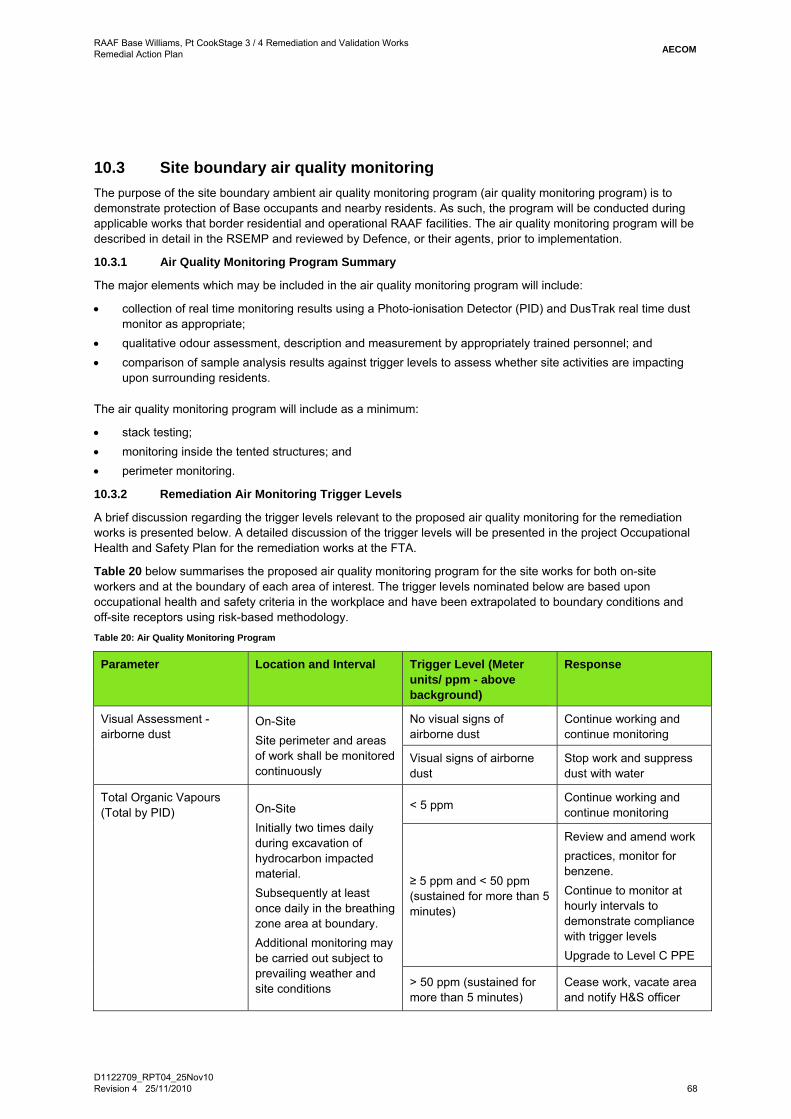
RAAF Base Williams, Pt CookStage 3 / 4 Remediation and Validation Works Remedial Action Plan
D1122709_RPT04_25Nov10 Revision 4 25/11/2010 68
AECOM
10.3 Site boundary air quality monitoring The purpose of the site boundary ambient air quality monitoring program (air quality monitoring program) is to demonstrate protection of Base occupants and nearby residents. As such, the program will be conducted during applicable works that border residential and operational RAAF facilities. The air quality monitoring program will be described in detail in the RSEMP and reviewed by Defence, or their agents, prior to implementation.
10.3.1 Air Quality Monitoring Program Summary
The major elements which may be included in the air quality monitoring program will include:
• collection of real time monitoring results using a Photo-ionisation Detector (PID) and DusTrak real time dust monitor as appropriate;
• qualitative odour assessment, description and measurement by appropriately trained personnel; and • comparison of sample analysis results against trigger levels to assess whether site activities are impacting
upon surrounding residents.
The air quality monitoring program will include as a minimum:
• stack testing; • monitoring inside the tented structures; and • perimeter monitoring.
10.3.2 Remediation Air Monitoring Trigger Levels
A brief discussion regarding the trigger levels relevant to the proposed air quality monitoring for the remediation works is presented below. A detailed discussion of the trigger levels will be presented in the project Occupational Health and Safety Plan for the remediation works at the FTA.
Table 20 below summarises the proposed air quality monitoring program for the site works for both on-site workers and at the boundary of each area of interest. The trigger levels nominated below are based upon occupational health and safety criteria in the workplace and have been extrapolated to boundary conditions and off-site receptors using risk-based methodology. Table 20: Air Quality Monitoring Program
Parameter Location and Interval Trigger Level (Meter units/ ppm - above background)
Response
Visual Assessment - airborne dust
On-Site Site perimeter and areas of work shall be monitored continuously
No visual signs of airborne dust
Continue working and continue monitoring
Visual signs of airborne dust
Stop work and suppress dust with water
Total Organic Vapours (Total by PID) On-Site
Initially two times daily during excavation of hydrocarbon impacted material. Subsequently at least once daily in the breathing zone area at boundary. Additional monitoring may be carried out subject to prevailing weather and site conditions
< 5 ppm Continue working and continue monitoring
≥ 5 ppm and < 50 ppm (sustained for more than 5 minutes)
Review and amend work practices, monitor for benzene. Continue to monitor at hourly intervals to demonstrate compliance with trigger levels Upgrade to Level C PPE
> 50 ppm (sustained for more than 5 minutes)
Cease work, vacate area and notify H&S officer

RAAF Base Williams, Pt CookStage 3 / 4 Remediation and Validation Works Remedial Action Plan
D1122709_RPT04_25Nov10 Revision 4 25/11/2010 69
AECOM
Parameter Location and Interval Trigger Level (Meter units/ ppm - above background)
Response
Odour (Odour surveys and PID)
On-Site Initially two times daily during excavation of hydrocarbon impacted material. Subsequently at least once daily during other times. Odour surveys carried out regularly on-site. Additional monitoring may be carried out subject to prevailing weather and site conditions
No odour or slight odour (just perceptible/barely recognisable) present.
Continue work and continue monitoring
Distinct odour present Instigate odour mitigation measures
Strong to very strong odour detected
Cease work until new work practices established
10.3.3 Community Consultation
Community consultation is a critical aspect of the remediation and will be necessary throughout the project start-up and remediation phases in order for the project to progress smoothly. .
A comprehensive community consultation and communication strategy must be implemented prior to commencement of the remediation works, The strategy must ensure that RAAF Base staff and nearby residents are adequately informed prior to commencement of and during implementation of the remediation works

RAAF Base Williams, Pt CookStage 3 / 4 Remediation and Validation Works Remedial Action Plan
D1122709_RPT04_25Nov10 Revision 4 25/11/2010 70
AECOM
“This page has been left blank intentionally”

RAAF Base Williams, Pt CookStage 3 / 4 Remediation and Validation Works Remedial Action Plan
D1122709_RPT04_25Nov10 Revision 4 25/11/2010 71
AECOM
11.0 Soil and Water Validation and Management Soil validation sampling to be undertaken as part of the remediation works will include:
• Excavation Validation Sampling – excavation validation sampling will be conducted after the excavation of DNAPL impacted soils
• Stockpile Sampling – excavated material will be stockpiled on site prior to characterisation and re-use in the excavations, selected for re-treatment or off-Site disposal.
• Imported Fill Validation Sampling – if required, an appropriate level of sampling of imported fill will be undertaken to confirm that the material being imported to the site is not contaminated and fit for use at the FTA.
In addition to the soil validation sampling, groundwater sampling will also be conducted as part of the management of the dissolved phase contamination. Groundwater will be monitored primarily along the east and south boundaries to the FTA.
All samples will be collected and analysed in accordance with the requirements outlined in the project Quality Plan and in accordance with industry standard sampling guidelines such as the National Environmental Protection Measures (NEPM) 1999 for Contaminated Land.
In addition to soils and groundwater quantitative validation criteria, the following qualitative validation criteria will be used:
• DNAPL Removal – validation of the remediation strategy will be based on removal of identified DNAPL to the extent considered practicable. A photographic record of the floor of each cell will be documented to show that DNAPL has been removed to the extent practicable.
11.1 Soil Validation Program and Protocols 11.1.1 Removal of DNAPL
On completion of excavation, the excavation floor is to be visually inspected, photographed and validation samples obtained (see Section 11.1.2). If after two days there is no visual evidence of NAPL seepage on the excavation floor, backfilling activities, with approved material, may commence.
11.1.2 Sampling of excavation floor
All soil samples will be collected using decontaminated sampling equipment and in accordance with appropriate sampling protocols. Samples will be labelled and placed directly into chilled storage containers (cool boxes under ice) for prompt transportation to the laboratory. All validation sample locations will be carefully recorded and documented.
A Photo-ionisation Detector (PID) is to be used during the soil validation works to screen samples for volatile organic compounds (VOCs). Soil samples will be collected from the overall floor of the full excavation area(s) on an approximately 20 m by 20 m grid. Excavation base samples will consist of discrete samples collected to a depth of 100mm into the base of the excavation at each location. A sub-sample will be placed in a sealed plastic bag for PID screening. PID results will be used in conjunction with field observations to aid in determining the extent to which impacted soils will be excavated.
Each soil sample will be analysed for volatile chlorinated hydrocarbons.
11.1.3 Stockpile Validation
Samples collected from stockpiled material will be collected at varying depths and locations of stockpiled material at a rate of 10 samples per stockpile, or 1 sample per 100 m3, whichever is greater. This will be required on both the pre- and post-treated soils.
Should the quantities of stockpiled material significantly exceed those anticipated by this RAP, consideration will be given to adjusting the sample frequency.
Stockpile validation samples are to be analysed for TPH, MAH, VCH and heavy metals. At least one in ten samples should be analysed for the full suite of analytes (including ASLP) as provided in Table 2 of EPAV IWRG guideline 621 “Soil Hazard Categorisation and Management” - June 2009.

RAAF Base Williams, Pt CookStage 3 / 4 Remediation and Validation Works Remedial Action Plan
D1122709_RPT04_25Nov10 Revision 4 25/11/2010 72
AECOM
Soils meeting NEPM open space criteria are considered suitable for backfilling the excavations.
11.1.4 Imported Fill Sampling and Validation
Importing fill may be required as part of the remediation works to reinstate excavations
In this event the frequency of validation sampling will be dependant on the source of the fill material. If the material is brought to the FTA from a quarry, and the material is homogeneous,
validation will consist of:
• a certificate warranting that the material is Virgin Excavated Natural material (VENM) or demonstrating the physical and chemical quality of the fill, including supporting test data.
If the imported material cannot be certified as VENM or clean quarry material, the frequency of testing will be:
• One sample per 100 m3, or a minimum of 3 samples per source.
Imported fill validation samples should be analysed for the full suite of analytes (including ASLP) as provided in Table 2 of EPAV IWRG guideline 621 “Soil Hazard Categorisation and Management” - June 2009.
Whenever possible, samples will be collected from the source location, prior to import of the material to the FTA.
Imported material must meet Fill Material criteria as defined in the above document.
11.2 Sample Location Surveying A registered surveyor will survey all validation sample points located in the remedial excavations. Proposed validation sampling will be based on square grid patterns. An initial grid cell will be selected (randomly on the validation area boundary) to mark the start of the relevant square grid that covers the entire validation area. The initial grid cell will be aligned and coincident with the validation area boundary, and the samples will be obtained from the centre of the grid cell.
11.3 Air Emissions Testing In addition to the validation sampling discussed above, it is recommended that flux emission sampling be undertaken to confirm that the remediation objectives have been met. Flux emissions sampling using Summa Canisters and sorbent (carbon) tubes is proposed in the following locations:
• on the treated material after reinstatement in the excavation cells to confirm that volatile PCIs have been adequately removed (and are not of significance from the underlying groundwater) and meet the remediation objectives; and
• at three locations along the eastern boundary with Point Cook Coastal Park
The methodology for flux emission sampling, sampling frequency and the analytical list will be agreed with Defence.
It is recommended that sampling be undertaken immediately prior to commencement of the remediation works (baseline), at bi-monthly intervals during the remediation works to monitor for fugitive emissions and on completion of the remediation program. The need for further monitoring will be provided in the Annual Report,
There is the potential for workers involved in intrusive activities (such as during construction works) on the Site to be exposed to PCIs in soils. As the soils are to remain within the FTA, intrusive works will be managed under existing site management plans that include health and specific safety requirements and work permits.
The results from air emissions testing will be used in the post-remediation Human Health Risk Assessment.
11.4 Water Sampling Program The following sampling program and protocols will be implemented at the commencement of remedial works. However, as analytical data is generated and analysed through the course of the project, trends may emerge which allow the program to be modified.

RAAF Base Williams, Pt CookStage 3 / 4 Remediation and Validation Works Remedial Action Plan
D1122709_RPT04_25Nov10 Revision 4 25/11/2010 73
AECOM
All water samples will be collected using decontaminated sampling equipment and in accordance with appropriate sampling protocols. Samples will be labelled and placed directly into sealed laboratory supplied appropriately preserved containers and stored in a cool box under ice for prompt transportation to the laboratory.
11.4.1 Groundwater Sampling
• Prior to commencing excavation works, one initial round of groundwater samples will be collected from selected monitoring wells. The purpose of the initial sampling round is to provide a “baseline” data set and represent the starting point for the ongoing groundwater monitoring program required by the proposed remediation and management measures.
• On completion of DNAPL remediation works, further rounds of groundwater sampling will be undertaken at six monthly intervals over a two year period to assess the effectiveness in adopting MNA to manage dissolved phase contamination.
The groundwater sampling will involve the collection of groundwater samples from the monitoring wells using passive diffusion sampler bags. Samples will be placed directly into laboratory supplied sampling containers containing relevant preservatives.
The results of the groundwater monitoring program will be assessed to:
• Demonstrate a steady or continuing decreasing trend in groundwater contaminant concentrations of the 12 PCIs. The results from the groundwater monitoring events will be reviewed annually and recommendations made to increase / decrease the extent of monitoring activities and to review the need to amend the dissolved phase remediation strategy;
• Demonstrate that the groundwater quality and extent of residual contamination continues to be protective of the sensitive receptors; and
• Demonstrate that the remediation goals will ultimately be accomplished.
11.5 Laboratory Analytical Methods A NATA accredited laboratory will undertake the majority of the laboratory analysis associated with this project. All analyses will be carried out in accordance with accepted Australian Standards.
11.5.1 Soil Sampling Analytical Methods
Soil samples will be analysed in accordance with currently accepted analytical methods that are compliant with those specified in Schedule B (3) of the 1999 National Environmental Protection Measures (NEPM).
11.5.2 Groundwater Sampling Laboratory Analytical Methods
Excavation waters and groundwater will be analysed in accordance with the methods prescribed by Schedule B (3) of the 1999 National Environmental Protection Measures (NEPM).
11.6 Documentation and Reporting A fortnightly summary report of the activities undertaken at the site will be provided to Defence. This report will also contain all analytical results obtained for the period, as well as progressive volumes of material excavated and/or remediated.
In addition, each report should be continuously reviewed and updated to take account of changes that arise during the remediation program.
11.6.1 Progress Reports
Progress reports will be provided to Defence in addition to the formal reporting and meeting requirements and will include: work completed during the reporting period; work proposed for the next reporting period; progress measured against schedule and budget; and issues that may have emerged and proposed actions to manage those issues.
11.6.2 Remediation and Validation Report
The final remediation and validation report will include:
• photographic record of excavations and excavation floors;
RAAF Base Williams, Pt CookStage 3 / 4 Remediation and Validation Works Remedial Action Plan
D1122709_RPT04_25Nov10 Revision 4 25/11/2010 74
AECOM
• NATA registered laboratory analytical certificates; • interpretive summary tables; • an overview of the works carried out during the remediation period; • the basis for the remediation approach; • surveyed figures outlining the extent of the remediation works; • the location of validation and characterisation samples; and • a risk assessment, using the C-RAT, demonstrating that the site has been remediated to an extent such that
the risk to Defence is considered acceptable.
Given the nature of the site works and the proposed schedule, fortnightly updates to Defence are recommended during remediation activities.

RAAF Base Williams, Pt CookStage 3 / 4 Remediation and Validation Works Remedial Action Plan
D1122709_RPT04_25Nov10 Revision 4 25/11/2010 75
AECOM
12.0 Key Personnel The contractual structure for delivery of the remediation works and management measures includes:
• A Contract Administrator engaged by Defence, and responsible for overseeing the works and administering the construction Contract.
• An independent Contractor, also engaged by Defence, and responsible for completion of the actual physical works according to a design prepared by others.
• An environmental consultant, who will be responsible for the monitoring and validation programs as well as technical oversight of the independent contractor.
• The Environmental Auditor engaged by Defence and responsible for the completion of the Section 53 V Environmental Audit.
The roles of key personnel, based on a contractual structure which incorporates a Contractor and Contract Administrator and Environmental Consultant, are described below.
12.1 Contract Administrator The Contract Administrator is responsible for ensuring that the remedial works undertaken on-site are in accordance with this RAP, the RSEMP, and other relevant documentation, and that the objectives stated within the RAP are ultimately met. The Contract Adminsitrator will generally also be responsible for ensuring that the project occurs within the timeframe nominated and within the financial budget allocated.
The Contract Adminstrator assumes ultimate responsibility for the project.
12.2 Environmental Consultant The environmental consultant’s team will consist of environmental scientists and/or engineers, who will assist the Contract Adminsitrator with the collection of soil validation samples and with other day-to-day tasks that arise, including the reporting of activities undertaken, maintaining accurate records of works and maintaining a photographic record of works undertaken.
The Environmental Consultant will be responsible for preparation of validation reports, sampling reports and progress reports associated with the environmental aspects of the remediation work.
12.3 Contractor The Contractor is responsible for daily operations and directs the site operations to ensure effective planning, verification, documentation and management of operational and environmental issues in accordance with this RAP. This includes maintaining a liaison with the Contract Administrator to ensure that all necessary work is undertaken to Defence’s satisfaction that the site is suitable for use, as per the objectives of this RAP.
The Contractor is responsible for the implementation of all Project Plans including the RAP, EMP, OHSP and other relevant contractual documents associated with the remediation works. This includes responsibility for:
• any design that may be required during the work; • implementation and scheduling of the remedial works in accordance with the abovementioned documents;
and • ensuring compliance with relevant legislation and regulations.
The Contractor is also responsible for ensuring that human health and the environment are protected at all times, including the provision of training and site inductions to all appropriate subcontractors and workers.
The Contractor will be a primary community contact and the first point of contact for sub-contractor issues.
RAAF Base Williams, Pt CookStage 3 / 4 Remediation and Validation Works Remedial Action Plan
D1122709_RPT04_25Nov10 Revision 4 25/11/2010 76
AECOM
12.4 Subcontractors The Contractor engaged to complete the remediation works may or may not engage subcontractors to complete elements of the remediation work. All work, irrespective of whether completed by the contractor itself or subcontractors will be undertaken, as specified by the Contractor Project Manager, and per the requirements stated within this RAP and the EMP, OHSP and relevant management plans.
Subcontractors will be advised of required work procedures through induction, training, and meetings provided by the Contract Administer and/or the Contractor. Maintenance of subcontractor equipment will be the responsibility of the subcontractors.
The Subcontractor is responsible for ensuring that all works executed by the subcontractor complies with relevant Work Cover Victoria legislation / guidelines as necessary.
12.5 Environmental Auditor It is understood that the Environmental Auditor will be engaged by Defence to complete a second Section 53V Environmental Audit. of the Fire Training Area. The scope of the second Audit will be to consider the impacts to groundwater and Port Phillip Bay associated with remediation activities being undertaken to address contamination from historical activities at the former Fire Training Area. This second audit will follow on from the original audit which considered the impacts to groundwater and Port Phillip Bay associated with historical activities at the former Fire Training Area and requirements for remediation.
The segments of the environment relevant to both audits are land, groundwater and surface water.

RAAF Base Williams, Pt CookStage 3 / 4 Remediation and Validation Works Remedial Action Plan
D1122709_RPT04_25Nov10 Revision 4 25/11/2010 77
AECOM
13.0 Limitations This document was prepared for the sole use of the Department of Defence and the regulatory agencies that are directly involved in the project, the only intended beneficiaries of our work. Any advice, opinions or recommendations contained in this document should be read and relied upon only in the context of the document as a whole and are considered current to the date of this document. Any other party should satisfy themselves that the scope of work conducted and reported herein meets their specific needs. AECOM cannot be held liable for third party reliance on this document, as AECOM is not aware of the specific needs of the third party.
From a technical perspective, the subsurface environment at any site may present substantial uncertainty. It is a heterogeneous, complex environment in which small subsurface features or changes in geologic conditions can have substantial impacts on water and chemical movement. Uncertainties may also affect source characterisation assessment of chemical fate and transport in the environment, assessment of exposure risks and health effects, and remedial action performance.
AECOM’s professional opinions are based upon its professional judgement, experience and training. These opinions are also based upon data derived from the testing and analysis described in this document. It is possible that additional testing and analysis might produce different results and/or opinions. AECOM has limited its investigation to the scope agreed upon with its client. AECOM believes that its opinions are reasonably supported by the testing and analysis that have been done, and that those opinions have been developed according to the professional standard of care for the environmental consulting profession in this area at this time. That standard of care may change and new methods and practices of exploration, testing, analysis and remediation may develop in the future, which might produce different results. AECOM’s professional opinions contained in this document are subject to modification if additional information is obtained, through further investigation, observations, or validation testing and analysis during remedial activities.

RAAF Base Williams, Pt CookStage 3 / 4 Remediation and Validation Works Remedial Action Plan
D1122709_RPT04_25Nov10 Revision 4 25/11/2010 78
AECOM
“This page has been left blank intentionally”

RAAF Base Williams, Pt CookStage 3 / 4 Remediation and Validation Works Remedial Action Plan
D1122709_RPT04_25Nov10 Revision 4 25/11/2010 79
AECOM
14.0 References • AECOM 2009a. Groundwater Monitoring Event – Month 12. RAAF Williams, Fire Training Area, Point Cook,
Victoria. • AECOM, 2009b. Ecological Risk Assessment – Phase 2, Draft Revision 01, RAAF Williams, Fire Training
Area, Point Cook, Victoria¸ August 2009. • AECOM 2010a. Remediation Feasibility Study (RFS). RAAF Williams, Fire Training Area, Point Cook,
Victoria¸ • AECOM 2010b. Groundwater Monitoring Event – Month 28. RAAF Williams, Fire Training Area, Point Cook,
Victoria¸ • AECOM 2010c. Groundwater Monitoring Event – Month 30. RAAF Williams, Fire Training Area, Point Cook,
Victoria¸ • AECOM 2010d. Groundwater Management Plan. RAAF Williams, Fire Training Area, Point Cook, Victoria¸ • AECOM 2010e. Conceptual Site Model. RAAF Williams, Fire Training Area, Point Cook, Victoria¸ • AECOM 2010f. Remediation Feasibility Study. RAAF Williams, Fire Training Area, Point Cook, Victoria¸ • AECOM 2010g. Groundwater Monitoring Event – Month 33. RAAF Williams, Fire Training Area, Point Cook,
Victoria¸ • Aquifer Solutions / AECOM, 2010, Draft Field Trials Implementation Report for In Situ Chemical Oxidation
for DNAPL Treatment, Aquifer Solutions Inc. / AECOM Australia, March 2010. • Department of Defence, 2007. Defence Contamination Risk Assessment Tool. Version 2 (16 February
2007). • ENSR, 2008a. Groundwater Monitoring Report: Month 3, RAAF Williams, Fire Training Area, Point Cook.
ENSR Australia, January 2008. • ENSR 2008b. Ecological Risk Assessment, Phase 1: RAAF Williams, Fire Training Area, Point Cook. ENSR
Australia, February 2008. • ENSR, 2008c. Groundwater Monitoring Report: Month 6, RAAF Williams, Fire Training Area, Point Cook.
ENSR Australia, March 2008. • ENSR 2008d, Initial Environmental Review, RAAF Williams, Former Fire Training Area, Pt Cook, Victoria.
ENSR Australia, June 2008 • ENSR, 2008e. Groundwater Monitoring Report: Month 9, RAAF Williams, Fire Training Area, Point Cook.
AECOM-ENSR Australia, July 2008. • EPA USA, State of Ohio, 2007. Technical Manual for Ground Water Investigations, Chapter 5. • HLA. 2003. Due Diligence Environmental Investigation. RAAF Williams, Point Cook, Victoria, HLA-
Envirosciences Pty Ltd. • HLA. 2004. Groundwater Contamination and Source Delineation at Former Fire Training Area. RAAF
Williams, Point Cook, Victoria, HLA-Envirosciences Pty Ltd. April 2004. • HLA. 2006a. Draft Initial Remediation Action Plan, Former Fire Training Area. RAAF Williams, Point Cook,
Victoria, HLA-Envirosciences Pty Ltd. • HLA. 2006b. Draft Remediation Feasibility Study. RAAF Williams, Point Cook, Victoria, HLA-Envirosciences
Pty Ltd. • HLA. 2006c. Further Assessment Report, Fire Training Area. RAAF Williams, Point Cook, Victoria, HLA-
Envirosciences Pty Ltd. February 2006. • HLA. 2006d. Short Term Pump Test Results - Fire Training Area, RAAF Williams Point Cook. RAAF
Williams, Point Cook, Victoria, HLA-Envirosciences Pty Limited. November 2006. • HLA. 2007a. Groundwater Discharge Mechanisms Report, Fire Training Area. RAAF Williams, Point Cook,
Victoria, HLA-Envirosciences Pty Ltd. June 2007. • HLA. 2007b. Groundwater Monitoring Plan. RAAF Williams, Point Cook, Victoria, HLA-Envirosciences Pty
Ltd. • HLA ENSR. 2007a. Groundwater Monitoring Event - Baseline. RAAF Williams, Point Cook, Victoria, HLA-
Envirosciences Pty Ltd. June 2007.

RAAF Base Williams, Pt CookStage 3 / 4 Remediation and Validation Works Remedial Action Plan
D1122709_RPT04_25Nov10 Revision 4 25/11/2010 80
AECOM
• HLA ENSR. 2007b. Human Health Risk Assessment, Point Cook Foreshore, Former Fire Training Area. RAAF Williams, Point Cook, Victoria, HLA-Envirosciences Pty Ltd. July 2007.
• HLA ENSR. 2007c. Draft In Situ Chemical Oxidation Study, Former Fire Training Area. RAAF Williams, Point Cook, Victoria, HLA-Envirosciences Pty Ltd. August 2007.
• HLA ENSR. 2007d. Draft Remediation Action Plan – Discharge Zone, Former Fire Training Area. RAAF Williams, Point Cook, Victoria, HLA-Envirosciences Pty Ltd.
• HLA ENSR. 2008a. Draft Ecological Risk Assessment, Phase 1. RAAF Williams, Point Cook, Victoria, HLA-Envirosciences Pty Ltd.
• HLA ENSR. 2008b. Groundwater Monitoring Event – Month 3. RAAF Williams, Point Cook, Victoria, HLA-Envirosciences Pty Ltd.
• HLA ENSR. 2008c. Groundwater Monitoring Event – Month 6. RAAF Williams, Point Cook, Victoria, HLA-Envirosciences Pty Ltd.
• Standards Australia/ Standards New Zealand, 2004. Risk Management. AS/NZS 4360:2004, 3rd Edition.

RAAF Base Williams, Pt CookStage 3 / 4 Remediation and Validation Works Remedial Action Plan
AECOM
Tables

Table T1Department of DefenceRAAF Base Williams, Pt Cook, VictoriaDNAPL Source ZonesPreliminary Technology Screening Matrix
Technology Sustainability
Technical Financial Logistical Timing Energy Use/Waste
40% 30% 10% 10% 10%
In Situ Steam Stripping Injection of steam into subsurface contaminants to
volatilise and mobilise contaminants.
4 4 4 4 3 Technology has been used for treatment of DNAPL source zones. Generally only suitable for sandy aquifers and may have limited efficiency for low permeability layers. Due to shallow nature of aquifer and unsaturated zone, source area would need an impermeable cap placed in order to manage steam zone, but also to prevent collapse of steam zone if large recharge event were to occur. Requires far
fewer injection wells and vapour recoevry wells than other in situ thermal technologies (TCH or ERH).
3.90
Excavation and ex situ thermal treatment
Desorption and/or destruction of organic contaminants in
excavated soil by heating, usually by direct heating thermal
unit.
5 2 3 4 2 Lower portion of aquifer material containing DNAPL would need to be excavated and staged prior to placement in an ex situ direct thermal treatment unit. Staging would require dewatering, and mixing
of DNAPL saturated material with other unsaturated material to reduced total percentage DNAPL volume in subsequent treatment batch. Staging would need to occur from toe of DNAPL zone to
allow material staging and handling over existing DNAPL zone.
3.50
Thermal Conductive Heating
Soil heating via in-well heaters or thermal blankets in the case
of very shallow soil to vaporise/volatilise fluids and contaminants. Temperatures
can be raised to above 450°C to remove semi-volatiles and other
recalcitrant compounds
5 2 4 3.5 2 Relies on relative uniform thermal conductivity of soil and therefore suitable for low permeability layers. However, unlike ERH, does not rely on moisture in soil to conduct heat and therefore can be operated at significantly higher temperatures (up to 500 oC) for removal of all organic compounds (if required). However, technology could be used to remove volatiles only which would reduce overall
cost by reducing energy requirements for creating very high temperature heated zone.
3.55
Electrical Resistive Heating Similar to TCH, however electrodes are used instead of
heater wells. Temperature cannot exceed 100 °C since
process requires transmission of heat via pore water.
4 2 4 3.5 2 Whilst may not be able to be used for removal of all organic compounds, technology suited to removal of volatile contaminants which may potentially impact on environmental receptors.
3.15
In Situ Chemical Oxidation Strong oxidants such as hydrogen peroxide,
permanganate or persulphate are injected into the subsurface
to degrade a wide range of organic contaminants.
4 3 4 2 4 Technology has been widely used for the treatment of DNAPL source zones. Bench scale trials have demonstrated up to 90% DNAPL mass destruction. Pilot scale field trials have indicated up to 26% mass destruction in a single application. Therefore multiple applications will be required to achieve
full efficacy.
3.50
Excavation and ex situ chemical treatment
Ex situ chemical stabilisation of DNAPL impacted soils.
3 2 2 3 3 Technology has been used for treatment of DNAPL source zones. Generally only suitable for shallow depth impacts and excavation will be difficult below water table. Excavated soils would have to be
contained in suitable vessels and chemically stabilised prior to replacement in excavations. DNAPL source zones will require to be contained within sheet pile wall or similar.
2.60
Multi-phase Extraction System
A high vacuum system is applied to simultaneously
remove various combinations of contaminated ground water,
separate-phase product (NAPL), and vapour from the subsurface
3 3 3 2 2 Technology is suitable for removal of DNAPL, dissolved phase and vapour phase mass. In many respects this option is a combination of DNAPL pumping coupled with an SVE sytem. Requires
DNAPL recovery, water and vapour phase treatment systems. Performance would be considerably enhanced if NAPL zone is contained and capped.
2.80
Surfactant and co-solvent extraction
Surfactant/Alcohol generally used in combination to lower interfacial tension, decrease
density and increase solubility leading to removal of free phase.
3 2 3 2 2 Surfactant/Alcohol generally used in combination to lower interfacial tension, decrease density and increase solubility leading to removal of free phase and residual DNAPL. Not effective in removing DNAPL trapped within unsaturated residual clay. Flushing fluid can be tailored to DNAPL mixtures and be used over moderate distances (up to 50 m) between injection and recovery wells. Requires
detailed knowledge of DNAPL composition to determine correct flushing fluid composition. Requires above ground treatment system for recovered DNAPL/ groundwater and surfactant separation.
2.50
Dewatering + Soil Vapour Extraction
Soil vapour extraction (SVE) is an in situ unsaturated (vadose)
zone soil remediation technology in which a vacuum is applied to the soil to induce the controlled flow of air and remove volatile
and some semi volatile
3 2 3 2 2 A containment cell with a cap would be required and dewatering to allow SVE to operate at maximum efficacy. Treatment of extracted groundwater required. Vapour treatment system required, or
alternatively condensation of collected vapours for off-site destruction. Only effective in removal of volatile compounds. System may need to operate for significant period given mass of DNAPL
(possibly up to 10 years or more).
2.50
Total Score
Remediation FeasibilityRemediation Technology Technology Description Comments
and some semi volatile contaminants from the soil. The
recovered vapour requires treatment to recover or destroy
the contaminantsDNAPL Pumping Traditional vertical wells or horizontal wells are used to
extract DNAPL from subsurface
2.5 3 4 2 2 Will reduce the mass of DNAPL in the subsurface, but approach will not allow complete removal below residual saturation due to capillary pressure limitations. DNAPL which is extracted will require treatment at a licensed facility or will require on-site destruction with another treatment technology.
2.70
Excavation, chemical stabilisation and physical containment away from
FTA.
Ex situ chemical stabilisation of DNAPL impacted soils.
2.5 2 1 3 3 Technology has been used for treatment of DNAPL source zones. Generally only suitable for shallow depth impacts and excavation will be difficult below water table. Excavated soils would have to be
contained in suitable vessels and chemicaly stabilised prior to replacement in excavations. Treated soils will have to be placed in a suitable containment cell away from FTA, but elsewhere at RAAF
Base Williams, Point Cook.
2.30
In Situ Chemical Reduction Technology suitable for wide range of chlorinated solvents.
Highest efficacy in DNAPL depletion achieved through
mixing of source zone soils with iron and bentonite slurry to
reduce groundwater flow through DNAPL zone. Technology also
proven for dissolved phase degradation of contaminants.
2 3 3 2 3 ZVI/Bentonite has been applied to a number of source zones in North America. However, ZVI is not effective for treatment of main volatile constituent, (1,2-dichloroethane). Nonetheless, approach
would be effective for many other chlorinated compounds which are present and also reduce mass flux from source zone.
2.50
In Situ Stabilisation or Solidification
Encapsulation of contaminants by in situ blending with chemical
binders to immobilise contaminants of concern.
1 2 3 3 2 Technology has not typically been applied for treatment of DNAPL source zones. 1.80
Enhanced In Situ Bioremediation (EISB)
Destruction of organic compounds in subsurface
contaminated soil by microorganisms.
2 3 2 1 4 Technology proven for the degradation of dissolved phase mass. Recent ITRC guidance document indicates that ISEB may be suitable for use in some DNAPL source zones. The system is suitable for
biodegradable organics, and would not remove recalcitrant compounds. Timeframe for this technology to operate in such a large saturated DNAPL source zone would be very long in
comparison with other DNAPL removal technologies, but may be more feasible economically in comparison with other technologies that require significant ex situ treatment (e.g. pump and treat).
2.40
Excavation and off-Site disposal to landfill
Excavate impacted soils, treat on surface and dispose to a
suitably licensed landfill
2 1 1 2 1 Technology does not comply with EPA waste hierarchy. Energy intensive. Excavated soils would have to be contained in suitable vessels and chemicaly stabilised prior to disposal off-Site. Stringent OH&S
and soil vapour mitigation measures would have to be implemented.
1.50
Physical Containment Containment and capping of DNAPL source zone to prevent
or significantly reduce contaminant migration and to
prevent human and environmental exposure.
1 3 4 1 3 Does not remove contamination and would require long term management and deed restriction. Installation of cut-off walls may not satisfy regulatory requirements for source zone removal to the extent practicable. Bentonite wall will allow diffusive flux. Longevity of sheet pile wall may need to
consider potential corrosivity of groundwater and/or DNAPL.
2.10
Hydraulic Containment Groundwater pumping is one of the most commonly used groundwater remediation
technologies at contaminated sites. Objectives include removal of dissolved contaminants from
the subsurface, and containment
1 1 4 1 2 Technology proven for the removal of dissolved phase mass, but not effective approach for reduction of DNAPL mass. A treatment system would be required for removal of both organic and inorganic
contaminants. Treated water could possibly be reused on site or discharged to the Bay under license. However, unless DNAPL source zone is removed or significantly depleted the timeframe required for this technology to operate would be very long (>100 years) and would not be economically feasible.
1.40
Page 1 of 2 RAP Tables T1 ‐ T6_11Aug10.xlsx

Preliminary Technology Screening Matrix
Technology Sustainability
Technical Financial Logistical Timing Energy Use/Waste
40% 30% 10% 10% 10%
Total Score
Remediation FeasibilityRemediation Technology Technology Description Comments
Air-Sparging Air sparging is an in situ technology in which air is
injected through a contaminated aquifer. Injected air traverses horizontally and vertically in
channels through the soil column, creating an
underground stripper that removes contaminants by
volatilisation
1 1 4 1 2 Technology proven for the removal of volatile dissolved phase mass, but not considered effective for DNAPL. System would require soil vapour extraction wells and subsequent vapour phase treatment. Some potential risk for air channelling in heterogeneous fracture system leaving untreated zones as well as the potential for fugitive vapour emissions. Only suitable for volatile organics, and would not remove higher molecular weight organics. Unless DNAPL source zone is removed or significantly
depleted the timeframe required for this technology to operate would be very long (>100 years) and may not be economically feasible.
1.40
In Situ Vitrification In Situ vitrification (ISV) is another in situ S/S process
which uses an electric current to melt soil or other earthen
materials at extremely high temperatures (1,600 °C to 2,000 °C) and thereby immobilise most inorganics and destroy organic
pollutants by pyrolysis
1 1 1 2 1 Technology not suitable for saturated zone due to generation of steam and volatile emissions. Requires very high electrical energy consumption.
1.10
Monitored Natural Attenuation
Natural subsurface processes—such as dilution, volatilisation, biodegradation,
adsorption, and chemical reactions with subsurface
materials—are allowed to reduce contaminant concentrations to
acceptable levels.
0 0 0 0 0 Relies on natural degradation/retardation of dissolved phase plume. Unless DNAPL source zone is removed or significantly depleted the timeframe required would be very long (>100 years) and not
necessarily acceptable unless mass flax and concentrations are protective of human or environmental receptors.
0.00
Permeable Reactive Barrier A permeable reaction wall is installed across the flow path of a contaminant plume, allowing
the water portion of the plume to passively move through the wall. The contaminants will either be
degraded or retained in a concentrated form by the barrier
material
0 0 0 0 0 Technology not applicable for DNAPL source zone treatment 0.00
Supercritical Water Oxidation
Supercritical Water Oxidation (SCWO) is a high efficiency,
thermal oxidation process capable of treating a wide variety of hazardous and nonhazardous wastes.
0 0 0 0 0 Technology is not suitable for treatment of DNAPL source zones. Technology is typically used to treat small quantities of hazardous liquid waste/slurries in commercial reactors.
0.00
Excavation and ex situ bioremediation
Destruction of organic compounds in contaminated soil by microorganisms. Treatment occurs through soil amendment
and stockpiling or enclosed
0 0 0 0 0 Not considered as a suitable technology option for treatment of DNAPL impacted material 0.00
Soil Washing Physical/chemical process for scrubbing soils ex situ to
remove contaminants.
0 0 0 0 0 Not suitable for DNAPL zone treatment. 0.00
Electrokinetics Electrokinetic remediation uses electrochemical and
electrokinetic processes to desorb, and then remove,
0 0 0 0 0 No suitable for DNAPL treatment. Technology used for treatment of dissolved phase metals 0.00
Page 2 of 2 RAP Tables T1 ‐ T6_11Aug10.xlsx

Table T2Department of DefenceRAAF Base Williams, Pt Cook, VictoriaDNAPL Source ZonesPreliminary Technology Screening Matrix - Summary of Sensitivity Analysis
Rank Rank Rank
In Situ Steam Stripping 3.9 1 3.95 3 4.00 1Thermal Conductive Heating 3.55 2 4.08 2 3.88 3In Situ Chemical Oxidation 3.50 3 3.40 5 3.25 5
Excavation and ex situ thermal treatment
3.50 3 4.10 1 4.00 1
Electrical Resistive Heating 3.15 5 3.58 4 3.38 4Multi-phase Extraction
System2.80 6 2.70 7 2.75 6
DNAPL Pumping 2.70 7 2.55 10 2.50 8Excavation and ex situ
chemical treatment2.60 8 2.80 6 2.75 6
Surfactant and co-solvent extraction
2.50 9 2.60 8 2.50 8
Dewatering + Soil Vapour Extraction
2.50 9 2.60 8 2.50 8
In Situ Chemical Reduction 2.50 9 2.25 12 2.25 12
Total ScoreRemediation Technology Scenario A Total Score
Scenario B Total Score
Enhanced In Situ Bioremediation (EISB)
2.40 12 1.95 13 2.00 13
Excavation, chemical stabilisation and physical
containment away from FTA.
2.30 13 2.45 11 2.50 8
Physical Containment 2.10 14 1.60 16 1.50 16In Situ Stabilisation or
Solidification1.80 15 1.85 14 1.75 14
Excavation and off-Site disposal to landfill
1.50 16 1.75 15 1.75 14
Hydraulic Containment 1.40 17 1.35 17 1.00 18Air-Sparging 1.40 17 1.35 17 1.00 18
In Situ Vitrification 1.10 19 1.25 19 1.25 17Monitored Natural
Attenuation0.00 0.00 0.00
Permeable Reactive Barrier 0.00 0.00 0.00Supercritical Water Oxidation 0.00 0.00 0.00
Excavation and ex situ bioremediation
0.00 0.00 0.00
Soil Washing 0.00 0.00 0.00Electrokinetics 0.00 0.00 0.00
A B CTechnical 40% 50% 50%Financial 30% 10% 25%
Logistical 10% 10% 0%Timing 10% 25% 25%
Sustainability 10% 5% 0%
Page 1 of 1 RAP Tables T1 ‐ T6_11Aug10.xlsx

Table T3Department of DefenceRAAF Base Williams, Pt Cook, VictoriaDissolved Phase GroundwaterPreliminary Technology Screening Matrix
Screening assumes that contaminant mass flux from Source Zones has been depletedTechnology
Sustainability
Technical Financial Logistical Timing Energy Use/Waste
50% 25% 0% 25% 0%
In Situ Enhanced Bioremediation (ISEB)
Destruction of organic compounds in subsurface by microorganisms.
4 3 3 2 4
Technology proven for the degradation of dissolved phase mass. An in situ system for treatment of volatiles and low molecular weight organic compounds is essentailly similar to an air sparging system and is referred to as bioventing or biosparging. The system would typically operate at lower pressure with the aim of increasing oxygen levels within the aquifer and not stripping volatile components. Such a system may or may not require soil vapour extraction wells and subsequent vapour phase treatment, if required it may only operate as part of the initial start‐up to deal with high mass load. ISEB is only suitable for biodegradable organics, and would not remove recalcitrant compounds. ISEB would be more feasible economically compared with other technologies that require significant ex situ treatment (e.g. pump and treat). Some logistical constraints given that dissolved phase plumes extend off‐Site
3.25
Physical Containment
Containment and capping of source zone to prevent or significantly reduce contaminant migration and to prevent human and environmental exposure.
3 3 3 3 4Does not remove contamination and would require long term management. Installation of cut‐off walls would not satisfy regulatory requirement in removing free phase liquids to the extent practicable.
3
Natural subsurface processes—such as dilution, l tili ti bi d d ti d ti d R li t l d d ti / t d ti f di l d h l A h i
Remediation Technology Technology Description
Remediation Feasibility
Comments Total Score
Monitored Natural Attenuation
volatilisation, biodegradation, adsorption, and chemical reactions with subsurface materials—are allowed to reduce contaminant concentrations to acceptable levels.
3 4 4 1 4Relies on natural degradation/retardation of dissolved phase plume. Approach requires containment, or depletion of DNAPL sources such that mass flux is reduced to attenuation capacity of aquifer. If option includes containment significant contaminant mass remains at the Site.
2.75
Hydraulic Containment
Groundwater pumping is one of the most commonly used groundwater remediation technologies at contaminated sites. Objectives include removal of dissolved contaminants from the subsurface and containment of contaminated ground water to prevent migration.
4 1 3 1 1Technology proven for the removal of dissolved phase mass. A treatment system would be required for removal of contaminants. Pumping near coast could lead to seawater instrusion which would impact significantly on treatment requirements.
2.5
Multi‐phase Extraction System
A high vacuum system is applied to simultaneously remove various combinations of contaminated groundwater and vapour from the subsurface.
4 1 3 1 1
Technology is suitable for removal of dissolved phase and vapour phase mass. Requires both a water and vapour phase treatment system. There are also significant constraints in terms of installation of this type of system in off‐Site area given that dissolved phase plumes extend downgradient of the Site.
2.5
Air‐Sparging
Air sparging is an in situ technology in which air is injected through a contaminated aquifer. Injected air traverses horizontally and vertically in channels through the soil column, creating an underground stripper that removes contaminants by volatilisation. The recovered vapour requires treatment to recover or destroy the contaminants.
3 2 3 1 1
Technology proven for the removal of dissolved phase mass. System would require soil vapour extraction wells and subsequent vapour phase treatment. Some potential risk for air channeling in heterogeneous system leaving untreated zones from creation of preferential pathways as well as the potential for fugitive vapour emissions. Only suitable for volatile organics, and would not remove higher molecular weight organic contaminants.
2.25
A permeable reaction wall is installed across the
Permeable Reactive Barrier
A permeable reaction wall is installed across the flow path of a contaminant plume, allowing the water portion of the plume to passively move through the wall. The contaminants will either be degraded or retained in a concentrated form by the barrier material.
2 2 4 1 1
PRBs may contain a number of substrates for the remediation of a wide range of dissolved phase contaminants. Suitable substrates for chlorinated compounds would include carbon for adsorption of organic contaminants, zero valent iron. Zero valent iron would not be applicable for 1,2‐DCA which is a major component of the dissolved phase plume.
1.75
In Situ Chemical Oxidation
Strong oxidants such as hydrogen peroxide or sodium persulphate are injected into the subsurface to degrade a wide range of organic contaminants.
2 1 3 1 4
Technology generally used for treatment of discrete source zones and not generally applied for treatment of dissolved phase plumes. Unless source zone is treated, would require repeated application of oxidants to treat dissolved phase plume. Logistical constraints due to source zone and the associated dissolved phase plume extending off‐Site.
1.5
Soil Vapour Extraction
Soil vapour extraction (SVE) is an in situ unsaturated (vadose) zone soil remediation technology in which a vacuum is applied to the soil to induce the controlled flow of air and remove volatile and some semi volatile contaminants from the soil. The recovered vapour requires treatment to recover or destroy the contaminants.
1 1 3 1 2Not effective technology for treatment of groundwater contamination. Suited for shallow soil contamination with volatile compounds.
1
Thermal Conductive Heating
Soil heating via in‐well heaters or thermal blankets in the case of very shallow soil to vaporise/volatilise fluids and contaminants. Temperature cannot exceed 100 °C since process requires transmission of heat via pore water.
0 0 0 0 0Technology generally used for treatment of discrete source zones and not applied for treatment of dissolved phase plumes. Additionally, application of technology in off‐Site areas not considered to be practicable.
0
Electrical Resistive Heating
Similar to TCH, however electrodes are used instead of heater wells. Temperature can exceed
d0 0 0 0 0
Technology generally used for treatment of discrete source zones and not applied for treatment of dissolved phase plumes. Additionally application of technology in offsite areas not considered to 0Electrical Resistive Heating
100 °C since process does not require transmission of heat via pore water.
0 0 0 0 0 dissolved phase plumes. Additionally application of technology in offsite areas not considered to be practicable.
0
In Situ Steam StrippingInjection of steam into subsurface contaminants to volatilise and mobilise contaminants.
0 0 0 0 0Technology generally used for treatment of discrete source zones and not applied for treatment of dissolved phase plumes. Additionally application of technology in off‐Site areas not considered to be practicable.
0
In Situ S tabilisation or Solidification
Encapsulation of contaminant by in situ blending with chemical binders to immobilise contaminants of concern.
0 0 0 0 0Technology generally used for treatment of discrete source zones and not applied for treatment of dissolved phase plumes. Additionally application of technology in off‐Site areas not considered to be practicable.
0
In Situ Vitrification
In Situ vitrification (ISV) uses an electric current to melt soil or other earthen materials at extremely high temperatures (1,600 °C to 2,000 °C) and thereby immobilise most inorganics and destroy organic pollutants by pyrolysis.
0 0 0 0 0Technology generally used for treatment of discrete source zones and not applied for treatment of dissolved phase plumes. Additionally application of technology off‐Site is not considered to be practicable.
0
Surfactant and co‐solvent extraction
Surfactant/Alcohol generally used in combination to lower interfacial tension, decrease density and increase solubility leading to removal of free phase.
0 0 0 0 0Technology generally used for treatment of discrete source zones and not applied for treatment of dissolved phase plumes. Additionally application of technology off‐Site is not considered to be practicable.
0
Excavation and ex situ thermal treatment
Desorption and/or destruction of organic contaminants in excavated soil by heating, usually by direct heating thermal unit.
0 0 0 0 0Technology generally used for treatment of discrete source zones and not applied for treatment of dissolved phase plumes. Additionally application of technology off‐Site is not considered to be practicable.
0
Page 1 of 2 RAP Tables T1 ‐ T6_11Aug10.xlsx

Screening assumes that contaminant mass flux from Source Zones has been depletedTechnology
Sustainability
Technical Financial Logistical Timing Energy Use/Waste
50% 25% 0% 25% 0%
Remediation Technology Technology Description
Remediation Feasibility
Comments Total Score
Excavation and ex situ bioremediation
Destruction of organic compounds in contaminated soil by microorganisms. Treatment occurs through soil amendment and stockpiling or enclosed reactor vessel.
0 0 0 0 0Technology generally used for treatment of discrete source zones and not applied for treatment of dissolved phase plumes. Additionally application of technology off‐Site is not considered to be practicable.
0
Supercritical Water Oxidation
Supercritical Water Oxidation (SCWO) is a high efficiency, thermal oxidation process capable of treating a wide variety of hazardous and nonhazardous wastes.
0 0 0 0 0 Technology is not suitable for treatment of dissolved phase plumes. Technology is typically used to treat small quantities of hazardous liquid waste/slurries in commercial reactors.
0
Soil Washing Physical/chemical process for scrubbing soils ex situ to remove contaminants.
0 0 0 0 0 Not suitable for dissolved phase plume treatment. 0
Electrokinetics Electrokinetic remediation uses electrochemical and electrokinetic processes to desorb, and then remove, metals and polar organics.
0 0 0 0 0 Not suitable for organic contaminants. Technology used for treatment of dissolved phase metals. 0
Page 2 of 2 RAP Tables T1 ‐ T6_11Aug10.xlsx

Page 1 of 1 RAP Tables T1 ‐ T6_11Aug10.xlsxPage 1 of 1 RAP Tables T1 ‐ T6_11Aug10.xlsx
pp g
Table T4Department of DefenceRAAF Base Williams, Pt Cook, VictoriaDissolved Phase GroundwaterPreliminary Technology Screening Matrix - Summary of Sensitivity Analysis
Screening assumes that contaminant mass flux from Source Zones has been depletedRemediation Technology Scenario A
Total ScoreRank Scenario B
Total ScoreRank Scenario C
Total ScoreRank
In Situ Enhanced Bioremediation (ISEB) 3.4 1 3.3 1 3.25 1Monitored Natural Attenuation 3.3 2 2.75 3 2.75 3Physical Containment 3.1 3 3.05 2 3 2Hydraulic Containment 2.4 4 2.7 4 2.5 4Multi‐phase Extraction System 2.4 4 2.7 4 2.5 4Air Sparging 2.3 6 2.3 6 2.25 6Permeable Reactive Barrier 2 7 1.9 7 1.75 7In Situ Chemical Oxidation 1.9 8 1.85 8 1.5 8Soil Vapour Extraction 1.3 9 1.25 9 1 9Thermal Conductive Heating 0 0 0Electrical Resistive Heating 0 0 0In Situ Steam Stripping 0 0 0In Situ S tabilisation or Solidification 0 0 0In Situ Vitrification 0 0 0Surfactant and co‐solvent extraction 0 0 0Excavation and ex situ thermal treatment 0 0 0Excavation and ex situ bioremediation 0 0 0Supercritical Water Oxidation 0 0 0Soil Washing 0 0 0Electrokinetics 0 0 0
A B CTechnical 40% 50% 50%Financial 30% 10% 25%
Logistical 10% 10% 0%Timing 10% 25% 25%
Sustainability 10% 5% 0%

Page 1 of 1 RAP Tables T1 ‐ T6_11Aug10.xlsxPage 1 of 1 RAP Tables T1 ‐ T6_11Aug10.xlsx
t
Table T5Department of DefenceRAAF Base Williams, Pt Cook, VictoriaDNAPLRemediation Technology Matrix - DNAPL
Technology In Situ Steam Stripping Excavation and Ex Situ thermal treatment Thermal Conductive Heating Electrical Resistive Heating In Situ Chemical Oxidation
Technology Description
Injection of steam into subsurface to volatilise and mobilise contaminants.
Desorption and/or destruction of organic contaminants in excavated soil by heating,
usually by direct heating thermal unit.
Soil heating via in-well heaters or thermal blankets in the case of very shallow soil to vaporise/volatilise fluids and contaminants.
Temperatures can be raised to above 450 °C to remove semi-volatiles and other recalcitrant
compounds.
Similar to TCH, however electrodes are used instead of heater wells. Temperature cannot
exceed 100 °C since process requires transmission of heat via pore water.
Strong oxidants such as hydrogen peroxide, permanganate or persulphate are injected into
the subsurface to degrade a wide range of organic contaminants.
Technology Status Approach has been widely used worldwide for sites where DNAPL is present.
Technology has been used in Australia and overseas for reducing chlorinated hydrocarbon
sources
Proven technology for removal of recalcitrant compounds including DNAPL source zones
containing volatile and semi-volatile compounds.
Proven technology for removal of DNAPL source zones containing volatile organic
compounds and those semi-volatile organic compounds which can be removed at
temperatures up to 100 °C.
Technology proven for remediation of a wide range of organic contaminants.
Ability to Degrade/Remove DNAPL Source
The technology will reduce the mass flux to the dissolved phase groundwater and lead to a
reduction in contaminant mass migrating off-Site.
The technology requires the DNAPL and impacted soils and groundwater to be brought to the surface, blended with clean soil (so that the maximum concentration of organics does
not exceed 1%- 3%), treated and characterised for re-use on Site. Large soil volumes will require management and above ground
treatment, with extensive OH&S issues to be managed. The technology will reduce the mass flux to the dissolved phase groundwater to an acceptable level and lead to a considerable
reduction in contaminant mass migrating off-Site.
The technology will reduce the mass flux to the dissolved phase groundwater and lead to a
reduction in contaminant mass migrating off-Site.
The technology will reduce the mass flux to the dissolved phase groundwater and lead to a
reduction in contaminant mass migrating off-Site.
Depending upon the form of ISCO adopted, some form of contaiment, or hydraulic control
may also be required. The technology will reduce the mass flux to the dissolved phase
groundwater and lead to a reduction in contaminant mass migrating off-Site.
Secondary Treatment Requirements
Impacted water and soil vapours require surfacetreatment prior to discharge. - Soil vapours require surface treatment prior to
discharge to the atmosphere.Soil vapours require surface treatment prior to
discharge to the atmosphere. None
Sorbed & Diffused Mass RemovalMay remove sorbed volatile and some semi-volatile contaminants, but not contaminants
diffused into underlying clay aquitard.
May remove sorbed volatile and some semi-volatile contaminants, but not contaminants
diffused into underlying clay aquitard.
May remove sorbed volatile, some semi-volatile contaminants, and some contaminants diffused
into the upper parts of the underlying clay aquitard.
May remove sorbed volatile and some semi-volatile contaminants, but not contaminants
diffused into underlying clay aquitard.
May remove sorbed volatile and some semi-volatile contaminants, but not contaminants
diffused into underlying clay aquitard.
Secondary Aquifer Impacts May have a temporary (12 - 18 mths) negative impact on in situ bioattenuation. None
May have a temporary (12 - 18 mths) negative impact on in situ bioattenuation. Negligible
other impacts - assuming that the temperature can be kept below 120 °C.
May have a temporary (12 - 18 mths) negative impact on in situ bioattenuation.
Negligible. Need to mitigate against pH drop and potential to produce acid sulphate soils.
May have a temporary (12 - 18 mths) negative impact on in situ bioattenuation.
Timing Technology Implementation 3 to 6 months 3 to 6 months 3 to 6 months 3 to 6 months 2 to 3 months
Timing for DNAPL Treatment/Removal
12 to 15 monthsOn completion of in situ steam stripping the majority of VOCs and some SVOCs will be
removed; however, there may be some back diffusion of contaminants from impacted soils. Dissolved phase groundwater contamination could remain for a few decades if enhanced
bioremediation is not undertaken.
12 to 18 monthsSince source zones will be removed,
groundwater contamination is unlikely to persist. Some back difussion of contaminants from
untreated soils may persist.
9 to 12 monthsOn completion of thermal conductive heating
the majority of VOCs and some SVOCs will be removed; however, there may be some back
diffusion of contaminants from impacted soils. Dissolved phase groundwater contamination could remain for a few decades if enhanced
bioremediation is not undertaken.
12 to 15 monthsOn completion of electrical resistive heating the
majority of VOCs and some SVOCs will be removed; however, there may be some back
diffusion of contaminants from impacted soils. Dissolved phase groundwater contamination could remain for a few decades if enhanced
bioremediation is not undertaken.
12 to 15 monthsOn completion of in situ chemical oxidation the majority of VOCs and SVOCs will be removed; however, there may be some back diffusion of contaminants from impacted soils. Dissolved
phase groundwater contamination could remain for a few decades if enhanced bioremediation is
not undertaken.
Bench/Pilot Scale Trial Requirements
Some pilot scale trials may be required to ascertain treatment requirements. - Some pilot scale trials may be required to
ascertain treatment requirements.Some pilot scale trials may be required to
ascertain treatment requirements.
Bench and pilot scale testing have been undertaken with some success. Further bench
scale tesing may be likely should surfactant enhanced in situ chemical oxidation be
considered.
Monitoring Requirements Ongoing groundwater monitoring likely to be required.
Ongoing groundwater monitoring likely to be required.
Ongoing groundwater monitoring likely to be required.
Ongoing groundwater monitoring likely to be required.
Ongoing groundwater monitoring likely to be required.
Regulatory Acceptance Acceptable if no human health or environmental risk.
Acceptable if no human health or environmental risk.
Acceptable if no human health or environmental risk.
Acceptable if no human health or environmental risk.
Acceptable if no human health or environmental risk.
Community Acceptance Likely to be acceptable if no human health or environmental risk.
Consultation required - may be acceptable if no human health or environmental risk.
Likely to be acceptable if no human health or environmental risk.
Likely to be acceptable if no human health or environmental risk.
Likely to be acceptable if no human health or environmental risk.
Logistical Considerations No significant issues
Extensive OH&S issues to be mitigated and high risk of odours migrating beyond the Site
boundary towards residential areas. Dependantupon blending to enable mass to be treated.
No significant issues No significant issues No significant issues
Financial Considerations excl supervision and monitoring - $ 14 million to $ 18 million $ 20 million to $ 24 million - S-ISCO $ 7.25 million to $ 14.5 million
ISCO $ 5 million to $ 10 million
Sustainability Low.High energy use required.
Low.High energy use required.
Low.High energy use required.
Low.High energy use required.
High.Low energy use required.
Data Gaps
Number of wells and likely extraction rates and therefore treatment system requirements would
require evaluation prior to detailed design phase.
Some field trials may be required to ascertain the effects of blending and DNAPL viscosity on
plant throughput.
Number of wells and likely extraction rates and therefore treatment system requirements would
require evaluation prior to detailed design phase.
Number of wells and likely extraction rates and therefore treatment system requirements would
require evaluation prior to detailed design phase.
Bench scale and field testing have been undertaken for ISCO technology; but should
surfactant enhanced ISCO be adopted further evaluation would be required to assess the
effect of the surfactant on the physical properties of the DNAPL.
Overall Assessment
In situ steam stripping would be restricted to effectively treating impacts in the higher
permeability soils. As such, it would be difficult, or impossible, to use steam injection to treat the
diffused mass within the paludal clay and underlying aquitard.
Excavation and ex situ thermal treatment has the potential to remove the vast majority, if not
all, the DNAPL for treatment with a greater degree of certainty. The excavated soils will be blended with "clean" soil to achieve the correct mix for treatment (1% to 3% mass of organics). Viscosity of DNAPL (>120 cST) and tendency
for mixture to soidify upon oxidation may present some significant constraints in meeting
treatment blend requirements. Significant potential for odours to migrate off-Site and
extensive OH&S issues to be addressed and implemented prior to excavation works
commencing.
Thermal Conductive Heating through "heater wells" is considered to be the most effective in
situ thermal technology for the removal of volatile organic and those semi-volatile compounds which can be degraded at
temperatures up to 100 °C. Should multi-phase extraction wells also be constructed a significan
volume of DNAPL could be removed from the source zones and it is assumed that the effluents could be destoyed in a thermal
oxidiser.
Electrical Resistive Heating has the potental to destroy volatile organic compounds and those semi-volatile organic compounds which can be
removed at temperatures up to 100 °C. However, the geochemistry of the shallow sand
aquifer is likely to offer too low a resistivity to heat the impacted zone effectively.
Two forms of in situ chemical oxidation have been assessed. Scaling up the field trial
undertaken at the Site to full scale would be labour intensive and involve multiple
applications (potentially up to 5 - 7) of the three-part injection process to achieve a significan
treduction in volatile organic compounds.The second form is surfactant enhaced in situ
chemical oxidation, where natural surfctants are used to solubilise the DNAPL before strong
oxidants are used to destroy contaminants in place. The solubilised product must be carefully
managed to mitigate the potential for its discharge to Port Phillip Bay.
Feasibility Score
Technical 3 4.5 4 2 3
Financial 3 3 2 2 4
Logistical 4 2 4 4 4
Timing 3 3 4 3.5 3
Sustainability 2 2 2 2 4
Rating - Scenario A 3 3.40 3.20 2.35 3.50Rating - Scenario B 3.05 3.6 3.7 2.58 3.25Rating - Scenario C 3 3.75 3.50 2.38 3.25
Scenario A Scenario B Scenario CWeighting Weighting Weighting
Technical 40% 50% 50%Financial 30% 10% 25%Logistical 10% 10% 0%
Timing 10% 25% 25%Sustainability 10% 5% 0%

e
Page 1 of 1 RAP Tables T1 ‐ T6_11Aug10.xlsxPage 1 of 1 RAP Tables T1 ‐ T6_11Aug10.xlsx
requ re l wa lik be wa lik be
y
n
e
Table T6Department of DefenceRAAF Base Williams, Pt Cook, VictoriaDissolved Phase GroundwaterRemediation Technology Matrix - Dissolved Phase
Technology Enhanced In Situ Bioremediation (EISB) Monitored Natural Attenuation (MNA) Physical Containment/Capping
Technology Description
A number of electron donors or electron acceptors can be used to stimulate biological activity which can degrade a wide range of
contaminants under either aerobic or anaerobic conditions.
Natural subsurface processes—such as dilution, volatilisation, biodegradation,
adsorption, and chemical reactions with subsurface materials—are allowed to reduce
contaminant concentrations to acceptable levels.
Containment and/or capping of contaminated soto prevent or significantly reduce contaminant
migration and to prevent human and environmental exposure. Cut-off walls/low
permeability barriers to reduce/redirect groundwater flow.
Technology Status Technology proven for remediation of a wide range of organic contaminants.
Approach has been widely used worldwide for sites where contaminant plumes are
significantly attenuated.
Technology has been used in Australia and overseas for reducing rainfall infiltration and eliminating/reducing groundwater flow, and
contaminant mass flux.
Ability to Restore Beneficial Use
This technology would not be able to be used trestore the beneficial use of the aquifer Site wide. The technology would be used to treat
groundwater at the southern Site boundary and eliminate contaminated groundwater
discharging off-Site to Port Phillip Bay. This assumes that the mass flux from the source
zones has been reduced.
oTechnology will not restore beneficial use of th
aquifer site wide. However, degree of attenuation is such that it will reduce risks to the beneficial use off-Site. This assumes that the mass flux from the source zones has been
reduced.
This approach would not result in the restoration of the beneficial use of the aquifer. However, capping would reduce rainfall infiltration and
concomitantly reduce groundwater discharge to Port Phillip Bay. Low permeability barriers (sheepile, HDPE liner, etc. ) could be used to reduce
contaminated groundwater discharge to Port Phillip Bay.
Waste Generation None None None
Diffused Mass Removal
Diffused mass will not be reduced within the aquitard underlying the aquifer and will act as
long term source of groundwater contamination downgradient of treatment zone.
Diffused mass will not be reduced within the aquitard underlying the aquifer and will act as
long term source of groundwater contamination downgradient of treatment zone.
Technology will have no impact in reducing adsorbed/diffused mass within aquifer
downgradient of containment area.
Secondary Aquifer Impacts
The addition of amendments may cause some secondary aquifer impacts if not appropriately
managed. Typically excessive sulphate reduction can lead to generation of hydrogen sulphide and excessive organic carbon can
lead to increased volatile fatty acid production.
None None
Timing Technology Implementation 2 to 3 months N/A 2 to 3 months
Timing for Plume Remediation
6 to 12 monthsUnless source zone is depleted, plume may
require many decades to restore beneficial use. Back diffusion of mass stored in underlying
aquitard would be expected to persist for decades.
N/AUnless source zone is depleted, plume may
require many decades to restore beneficial use. Back diffusion of mass stored in underlying
aquitard would be expected to persist for decades.
3 to 6 monthsUnless source zone is depleted, plume may
require many decades to restore beneficial use. Back diffusion of mass stored in underlying
aquitard would be expected to persist for decades.
Bench/Pilot Scale Trial Requirements
Some bench scale trial may be required to assess preferred electron donor and dosing
rates.None None
MonitoringMonitoring Requirements
Ongoing groundwater monitoring likely to be required for assessment of performance as weli d for assessment of performance as we
as establishing field scale dosing rates of electron donors or elctron acceptors.
Ongoing groundwater monitoring likely to beOngoing ground ter monitoring ely to required.
Ongoing groundwater monitoring likely to beOngoing ground ter monitoring ely to required.
Regulatory Acceptance May be acceptable if no human health or environmental risk.
May be acceptable if no human health or environmental risk.
May meet some resistance if alternative options for mass removal are feasible.
Community Acceptance
Likely to be acceptable using an in situ remediation method.
May be acceptable if no human health or environmental risk.
May be acceptable if no human health or environmental risk.
Logistical Considerations
The timely delivery of amendments in heterogeneous formations may require closely
spaced wells.No constraints using this technology.
Capping of DNAPL source zones and construction of a physical barrier poses no
significant constraints.
Financial Considerations excl supervision and monitoring
Capital - $ 200 k to $ 300 kO&M - $ 100 000 to $ 150 000 per annum
Capital - $ 20 000 to $ 40 000O&M - $ 50 000 to $ 75 000 per annum
Capital - Sheet Pile Wall $ 1 m to $ 1.4 mCapital - capping $ 100 k to $ 150 k
O&M - $ 75 000 to $ 100 000 per annum
Sustainability
Low to Medium.Low energy use in deliverying amendments;
higher energy use for fully engineered bioventing & biosparging.
High.No energy use.
High.Low energy use post barrier and capping
construction.
Data Gaps
Bench scale work required to establish design field scale application rates. Pilot scale field
injection trial required to assess spacing requirements of full scale delivery system.
None None
Overall Assessment
EISB has been applied for the treatment of a wide range of biodegradable organic
contaminants in groundwater, but may not be effective for recalcitrant compounds. There ma
be some resistance from regulators to the re-injection of impacted groundwater into the
aquifer in the highly impacted areas.
The low hydraulic head and inferred attenuatiocapacity (post source zone remediation) is
expected to result in attenuation of dissolved contaminants in the shallow sand aquifer befor
discharging to Port Phillip Bay.
Does not remove contamination sources and does not directly improve groundwater quality.
Feasibility Score
Technical 4 3 3
Financial 3 4.5 2
Logistical 3 4 3
Timing 2 2 2
Sustainability 3.5 4 3
Rating - Scenario A 3.35 3.55 2.6Rating - Scenario B 3.275 3.05 2.65Rating - Scenario C 3.25 3.125 2.5
Scenario A Scenario B Scenario CWeighting Weighting Weighting
Technical 40% 50% 50%Financial 30% 10% 25%Logistical 10% 10% 0%
Timing 10% 25% 25%Sustainability 10% 5% 0%

RAAF Base Williams, Pt CookStage 3 / 4 Remediation and Validation Works Remedial Action Plan
AECOM
Figures


PORT PHILLIP BAY
INTERTIDALZONE
FORMER FIRETRAINING AREA
PIT A
PIT B
PIT CPIT D
PIT E
POINT COOKCOASTAL PARK
RAAF LAKE
PT COOKFLYING SCHOOL
AIRFIELD
Mound F
Mound G
0 100 20050
metres
´
1:5,000 (when printed at A3)
A3 size
AECO
M d
oes n
ot w
arra
nt th
e ac
cura
cy o
r com
plete
ness
of in
form
ation
disp
layed
in th
is m
ap a
nd a
ny p
erso
n us
ing it
does
so a
t the
ir ow
n ris
k. A
ECOM
shall
bea
r no
resp
onsib
ility o
r liab
ility f
or a
ny e
rrors
, fau
lts, d
efec
ts, o
r om
ission
s in
the
infor
mat
ion.
www.aecom.com
PROJECT ID
LAST MODIFIEDCREATED BY
D1122705ARTART 03 Jun 2010
DATUM GDA 1994, PROJECTION MGA ZONE 55
F2Figure
Department of Defence
SITE LOCALITY PLAN
Remedial Action PlanFire Training Area, RAAF Williams -Point Cook
Data sources:Aerial Photograph: (c) 2006 QASCO
Map Document: \\aumel1fp001\ENSR_GIS\GISMEL\D11227_Point Cook\05\ArcGIS\RAP Oct10\D1122705_FigF2_SiteLayout_21Oct10.mxd
LEGEND
Site Boundary - Chain Wire Mesh Fence
Former Fire Training Area
Approximate Extent of FTA Burning Pits/Areas as Delineatedby HLA Envirosciences 2004
Approximate DNAPL Extent
Approximate Extent of LNAPL Sheen
NAPL Extent

&;
@A
&;
@A
@A
&;
&;
&;
&;
&;
&;
&;
@A
&;&;
&º
&º
&º
&º&º
@A
@A
@A
@A
@A
@A
@A
@A@A@A
@A
&;@A@A
&;@A
@A
@A
@A
@A@A
@A
@A
@A
&;
&;
&;
&;
&;
&;
@A
@A
@A
@A
@A
@A
&;
&;
&;
&;
&;
&;
&;
&;
&;
&;
&;
&;CB
CB
CB
CB
&;
&;
&;
&;
@A
@A
@A
@A
@A
@A
@A
@A
@A
@A
@A
@A
@A
@A
!>
!>!>
!>
!>
!>
!>!>
!>!>
!>!>
!>!>
!>!>
!>!>
!>!>
"/
"/
"/
"/
"/
"/
"/
"/
"/
"/
&;
&;
&;
&;
&;
&; &;
&;
&;
&;&;
&;&;
&;&;&;
&;
&;
&;
&;&;
&;
&;&;&;
&;
&;
&;
&;
!.
!.
!.
!.
"/
&;
"/
"/
@A@A@A@A
@A@A
@A@A@A
@A
@A
@A@A
@AED
ED
ED
EDED
ED
ED
ED
ED
ED
ED
ED
ED
ED
ED
ED
ED
ED
ED
ED
ED
ED
ED
ED
ED
EDED
ED
ED
ED
ED
EDED
ED
ED
ED
ED
ED
ED
ED
ED
ED ED
ED
ED
ED
EDEDED
ED
ED
EDED
ED
ED
ED
ED
ED
ED
ED
ED
ED
ED
ED
ED
ED
ED
ED
EDED
ED
ED
EDED
ED
ED
ED
ED
ED
ED
ED
ED
ED
EDED
ED
&A
&A&A
&A
&A
&A&A
&A&A&A&A&A
&A&A&A&A&A&A&A&A&A&A&A&A&A&A&A&A
&A
&A
&A
&A
&A
&A
@A
@A
@A
@A
@A
@A
@A
@A
@A
@A
@A
@A
@%
@%
@%
@A
@A@A@A@A
@A
@A
@A
@A
@A@A@A
@A@A
@A
@A
@A
@A
@A
@A@A@A@A@A
@A
@A
@A
@A
@A
@A
@A@A
@A
@A
@A
Mound G
Mound F
Primary Source Zone A
Primary SourceZone B
PIT C
PIT D
PIT E
ADS LINE 1
SecondarySourceZone A
SecondarySourceZone B
Locationof ISCO
Field Trial
PORTPHILLIP
BAY
Intermediate Aquifer
F18MW
ADS LINE 3
ADS
LIN
E 2
ADS LINE 4
F70MW
F69MW
F67MW
F66MWR
F65MWR
F64MW
F63MWR
F62MW
F61MW
F60MW
F59MW
F58MW
F57MW
F55MW
F54MW
F53MW
F52MW
F49MWb
F48MWb
F44MW
F42MW
F41MW
F40MW
F39MW
F35MWb
SV01
F32MWc
F31MWc
F30MWb
F27MWc
F27MWb
F19MW
F18MW
F17MW
F13MW
F11MW
F10MW
F09MW
F08MW
F07MW
F06MWR^ F04MW^
F02MW^
F87MW
PropSV
PropSV
F16MW
ADS15
SV02
SV03
SV04
SV05
SV06
SV10
PDBS21
PDBS23
PDBS24
PDBS25
PDBS27
PDBS20
PDBS01
PDBS02PDBS03
PDBS05
PDBS06PDBS07
PDBS08
PDBS09
PDBS10
PDBS11
PDBS12
PDBS13
PDBS14
PDBS15
PDBS16
PDBS17
PDBS18
PDBS19
F12MWR
PDBS28
PDBS29
PDBS31
PDBS30
PropSV
eb06
isco04
isco02
isco01
isco14
isco13
isco12
isco12
isco11isco10
isco08
isco06
TP73
TP74TP80
TP75
TP76
TP77
TP78
TP25
TP69
TP79
ATP1
ATP3
ATP2
TP67
TP39
TP40
TP41
TP42TP43
TP44
TP46
TP47
TP49
TP51
TP52
TP53
TP54
TP55
TP56
TP57
TP58
TP45
TP59
TP01
TP02
TP03
TP04
TP05TP06
TP09
TP10TP11
TP24
TP28
TP29
TP26
TP27
TP12
TP13
TP14
TP15
TP16
TP17
TP18
TP19
TP20TP21
TP22
TP23
TP30
TP33TP34
TP37
TP38
TP36
TP35
TP32
TP31
TP62
TP60
TP61
TP63
TP64
TP65
TP66
TP81
TP71TP70TP72
TP68F88MW
F89MW
F90MW
F83MWc
F85MW
CW4
CW2CW1CW07
CW15
CW04
eb05
eb04
F87MW
eb03 eb02
eb01
AS08AS07
AS06
AS05
AS04
AS03
AS02
AS01
F13MWR
F12MW
F05MW^
ADS06
F51MW
F83MW
F82MW
F81MW
F80MW
F79MW
F78MW
F03MW^
F77MW
F76MW
F75MW
F74MW
F73MW
F72MW
F71MW
F45MW
F38MW
F37MW
F36MW
F34MW
F33MW
F30MWa
F29MWa
F28MW
F27MWa
F26MW
F25MW
F24MW
F23MW
F22MW
F21MW
F20MW
F14MWR
ADS20
ADS19
ADS16
ADS14
ADS13
ADS12
ADS11
ADS10
ADS09
ADS08ADS07
ADS05
ADS04 ADS03
ADS02ADS01
PCMB19^
PCMB18^
PCMB2^
F84MW
303300
303300
303350
303350
303400
303400
303450
303450
303500
303500
303550
303550
303600
303600
303650
303650
303700
303700
5798
950
5798
950
5799
000
5799
000
5799
050
5799
050
5799
100
5799
100
5799
150
5799
150
5799
200
5799
200
5799
250
5799
250
5799
300
5799
300
0 30 6015
metres
´
1:1,400 (when printed at A3)
A3 size
AECO
M d
oes n
ot w
arra
nt th
e ac
cura
cy o
r com
plete
ness
of in
form
ation
disp
layed
in th
is m
ap a
nd a
ny p
erso
n us
ing it
does
so a
t the
ir ow
n ris
k. A
ECOM
shall
bea
r no
resp
onsib
ility o
r liab
ility f
or a
ny e
rrors
, fau
lts, d
efec
ts, o
r om
ission
s in
the
infor
mat
ion.
DATUM GDA 1994, PROJECTION MGA ZONE 55
F3Figure
Map Document: \\aumel1fp001\ENSR_GIS\GISMEL\D11227_Point Cook\05\ArcGIS\RAP Oct10\D1122705_FigF3_AllGWBores_21Oct10.mxd
&A Cut off Wall Wells
@A ISCO FIeld Trial Bores
Proposed ADS Extension
Cut Off Wall
Aeration Delivery System
Planned Bore: Never Installed
Decomissioned/Destroyed Bore
&ºBore IDF18MW^
\ Damaged
CB
"/
!>
@A
!.
@A
@A Deep Aquifer Monitoring Well Location Intermediate Aquifer MonitoringWell Location
Passive Diffusion Bag Sampler
Shallow Aquifer Monitoring Well LocationAeration Delivery System Monitoring BoreBundle Piezometer
Soil Vapour Bore
Old Timber Post & Wire Fence
Site Boundary - Chain Wire Mesh Fence
Approximate DNAPL Extent
Approximate Extent of LNAPL Sheen
NAPL Extent
Approximate Extent of FTA Burning Pits/Areas as Delineated by HLA Envirosciences 2003
LegendF18MW
Test Pit LocationEDSoil Bore Location@A
www.aecom.com
PROJECT ID
LAST MODIFIEDCREATED BY
D1122705ARTART 03 Jun 2010
Department of Defence
LOCATION OF GROUNDWATERMONITORING WELLS, NAPLEXTENT, ADS LINES & CUT OFFWALL
Remedial Action PlanFire Training Area, RAAF Williams -Point Cook
Data sources:Aerial Photograph: (c) 2006 QASCO
&;
Inferred Extent of Intermediate Aquifer
Proposed Boundary Monitoring Well
Proposed Boundry Air QualityMonitoring Point@%
@A
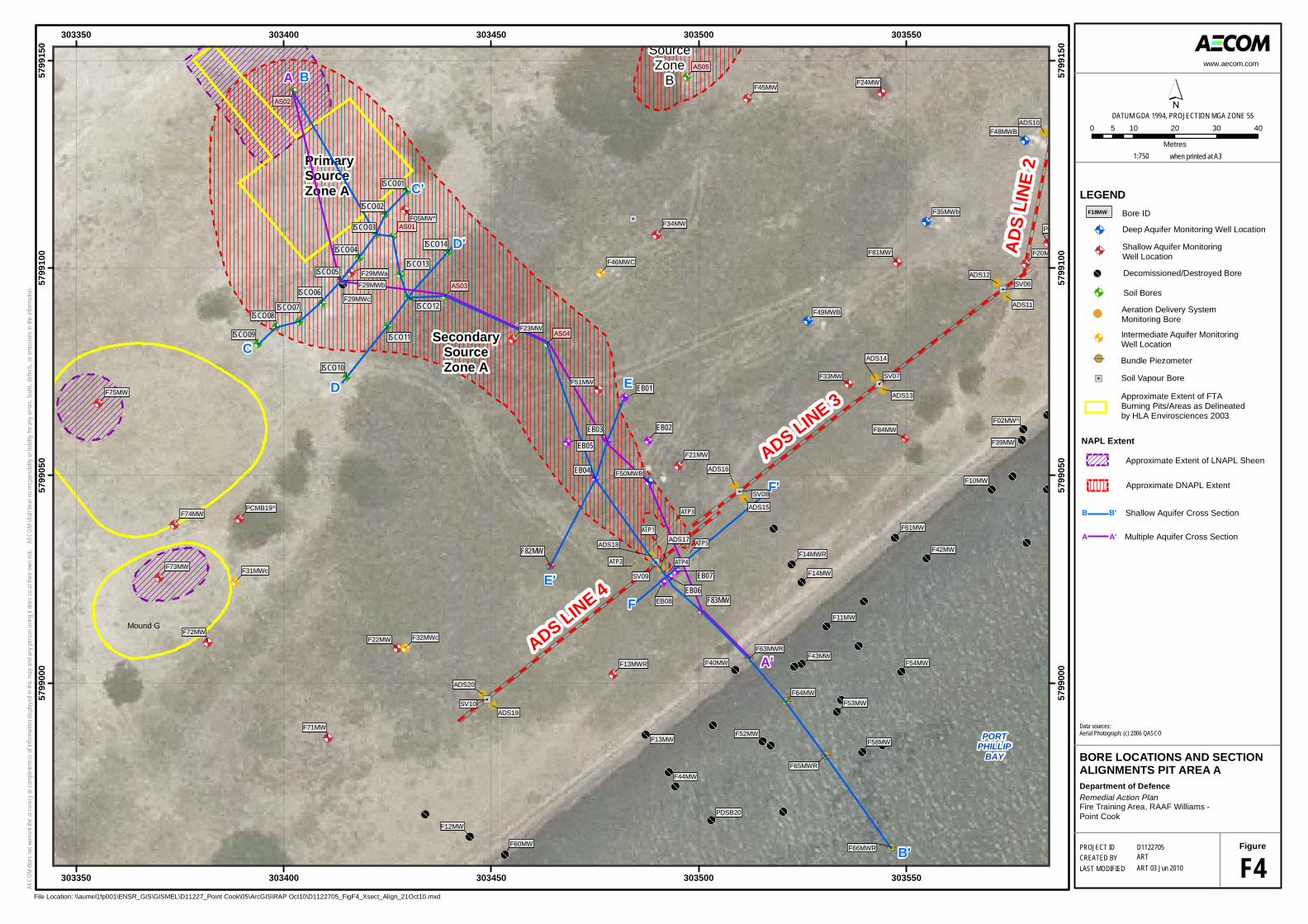
&;
@A
&;
&;
&;
&;
@A
&;
&;
@A
@A
@A
@A
@A
&;@A@A
@A
@A
@A
@A@A
&;
&;
&;
&;
&;
@A
@A
@A
@A
@A
@A
&;
&;
&;
&;
&;
&;
&;CB
CB
CB
CB
&;
@A
@A
@A
@A
@A
@A
@A
@A
!>
!>
!>
!>!>
!>!>
!>!>
!>!>
"/
"/
"/
"/
"/
"/
&;
&;&;
&;
&;
&;
&;
&;
&;&;
&;
&;
&;
&;
&;
"/
"/
@A
@A
@A
@A
@A@A
@A
@A
@A@A
@A
@A
@A
@A
@A
@A
@A
@A@A
@A
@A
@A
@A
@A
@A@A
@A
@A
@A
@A
Mound G
SourceZone
B
F84MW
PrimarySourceZone A
SecondarySourceZone A
F
F'
D'
C'
C
D
B'
B
E'
E
A
A'
ADS LINE 3
AD
S LI
NE
2
ADS LINE 4
SV10
ADS10
F81MW
F72MW
F71MW
F61MW
F54MW
F53MW
F52MW
F43MWF40MW
F39MW
F24MW
F14MW
F12MW
F10MW
PDSB20
F20M
F32MWc
F14MWR
F13MWR
EB07
EB06
EB02
EB01
EB08
SV09
SV08
ADS19
ADS18ADS17
ADS16
ADS15
F75MW
F74MW
F73MW
F64MW
F60MW
F58MW
F51MW
F45MW
F44MW
F42MW
F34MW
F23MW
F22MW
F21MW
F13MW
F11MW
F66MWR
F50MWB
F49MWB
F46MWC
F35MWb
F31MWc
F05MW^
PCMB19^
SV07
SV06
ADS20
ADS14
ADS13
ADS12
ADS11
F33MW
PC
F65MWR
F63MWR
F48MWB
F29MWb
F29MWa
F29MWc
F02MW^
F83MW
F82MW
ISCO14
ISCO09
ISCO01
EB05
EB04
EB03
ISCO13
ISCO12
ISCO11
ISCO10
ISCO08ISCO07
ISCO06
ISCO05
ISCO04
ISCO03
ISCO02
ATP2
ATP5
ATP4
ATP3
ATP1
AS02
AS05
AS04
AS03
AS01
303350
303350
303400
303400
303450
303450
303500
303500
303550
303550
5799
000
5799
000
5799
050
5799
050
5799
100
5799
100
5799
150
5799
150
LEGEND
F4Figure
File Location: \\aumel1fp001\ENSR_GIS\GISMEL\D11227_Point Cook\05\ArcGIS\RAP Oct10\D1122705_FigF4_Xsect_Align_21Oct10.mxd
Multiple Aquifer Cross SectionA'A
"/
CB
@A Intermediate Aquifer MonitoringWell Location
Bundle Piezometer
Soil Vapour Bore
!>Aeration Delivery System Monitoring Bore
B'B Shallow Aquifer Cross Section
Soil Bores@A
Decomissioned/Destroyed Bore
Bore IDF18MW^
@A
@A Deep Aquifer Monitoring Well Location
Shallow Aquifer Monitoring Well Location
Approximate DNAPL Extent
Approximate Extent of LNAPL Sheen
NAPL Extent
Approximate Extent of FTA Burning Pits/Areas as Delineated by HLA Envirosciences 2003
F18MW
PORTPHILLIP
BAY
&;
´DATUM GDA 1994, PROJECTION MGA ZONE 55
0 10 20 30 405
Metres1:750 when printed at A3
www.aecom.com
PROJECT ID
LAST MODIFIEDCREATED BY
D1122705ARTART 03 Jun 2010
Department of Defence
BORE LOCATIONS AND SECTIONALIGNMENTS PIT AREA A
Remedial Action PlanFire Training Area, RAAF Williams -Point Cook
Data sources:Aerial Photograph: (c) 2006 QASCO
AECO
M d
oes n
ot w
arra
nt th
e ac
cura
cy o
r com
plete
ness
of in
form
ation
disp
layed
in th
is m
ap a
nd a
ny p
erso
n us
ing it
does
so a
t the
ir ow
n ris
k. A
ECOM
shall
bea
r no
resp
onsib
ility o
r liab
ility f
or a
ny e
rrors
, fau
lts, d
efec
ts, o
r om
ission
s in
the
infor
mat
ion.

A
@AA
A A
CB
@A@A
!!
A
5
0
-5
-10
-15
-20
-25
-30
-35
5
0
-5
-10
-15
-20
-25
-30
-35
Pit A Grey Sand and Silty Sandwith some Gravel(Quaternary Aged)
Blue/ Green Marine Clay (Quaternary Aged)
Grey/ Orange/ Brown Silty Clay(Quaternary Aged)
Light Grey Silty Sand(Tertiary Aged, Brighton Group)
Grey/Orange Silty Clay(Tertiary Aged, Newport Formation)
SHALLOW AQUIFER
DEEP AQUIFER
INTERMEDIATE AQUIFER
AS02F29MWb
AS03 AS04 EB03 F50MWbF83MW
F63MWR
Ele
vatio
n m
AH
D
40 60 80 100 120 140 160 1800 20
Distance Along Baseline
Brown/ Grey Clayey Sand (Quarternary Aged)
PortPhillipBayAeration
Delivery System
Cut-OffWall
?
RAAF Lake
A A'
?
??
??
?
?
?
??
?
?
?
??
??
? ?
?? ????????
Primary SourceZone A Secondary Source Zone
IntertidalDischarge
Zone
AECO
M d
oes n
ot w
arra
nt th
e ac
cura
cy o
r com
plete
ness
of in
form
ation
disp
layed
in th
is m
ap a
nd a
ny p
erso
n us
ing it
does
so a
t the
ir ow
n ris
k. AE
COM
shall
bea
r no
resp
onsib
ility o
r liab
ility f
or a
ny e
rrors
, fau
lts, d
efec
ts, o
r om
ission
s in
the
infor
mat
ion.
www.aecom.com
A3 size
PROJECT ID
LAST MODIFIEDCREATED BY
D1122705ARTART 03 Jun 2010 F5
Figure
Department of Defence
IDEALISED MULTIPLE AQUIFERCROSS SECTION A-A' THROUGHSECONDARY SOURCE ZONE A
Remedial Action PlanFire Training Area, RAAF Williams -Point Cook
Map Document: \\aumel1fp001\ENSR_GIS\GISMEL\D11227_Point Cook\05\ArcGIS\RAP Oct10\D1122705_FigF5_A-A_Xsect_21Oct10.mxd
LEGEND
Clays (Aquitard)
Silty Sand
Clayey Sand
DNAPL
Aquifer
Semi Confining Layer? ?
Inferred Lithologic Boundary? ?Approx Vertical Exaggeration x2.15
Metres
0 7.5 15 22.5 30
Vertical Groundwater Flow

RAAF Base Williams, Pt CookStage 3 / 4 Remediation and Validation Works Remedial Action Plan
AECOM
Appendix A RAAF Base Williams, Point Cook Contamination Risk Assessment Tool (CRAT)

Table A1Department of DefenceRAAF Base Williams, Pt Cook, VictoriaCRAT - Pre-Remediation
Location: RAAF Base Williams, Pt Cook, Fire Training Area Date Revised: 11-Jun-10
Description:
Risk assessment:
Contaminants: Hydrocarbons including, but not limited to; PCE; TCE; 1,1,2-TCA; 1,2-DCA; 1,1-DCA; VC; benzene; chlorobenzene; chloroform; cis-1,2-DCE; and trans 1,2-DCE.
Asset Type: To be confirmed by Defence
Receptor Pathway Risk Dimension
Likelihood of the Risk Scenario Consequence
Occurring
Consequence Rating Consequence Justification
Risk Score (Likelihood +
Consequence)
Risk Level(Low, Medium,
High, Very High)
Risk Band and Priority
Capability 7 11
Has some potential to affect Defence activities. FTA is located near active zones of the Site and it is not currently essential to Base operations. However, it is possible that the area may be used for future above ground training activities (i.e. : no digging).
18 Medium
Extensive contamination within the Shallow Sand Aquifer underlying the FTA together with several surface waste stockpiles
A Human Health Risk Assessment (HHRA - HLA, 2007) found that the Site was not considered to pose an unacceptable risk to human health (for the scenarios considered) provided access to the Site was restricted. A Phase 1 & 2 Ecological Risk Assessment (ERA - HLA, 2008 & AECOM, 2009) found that epifaunal and infaunal benthic invertebrates, bottom feeding fish, plants and microorganisms were considered to be most at risk from contaminated groundwater migrating from the FTA. The study concluded that while Site-derived contaminants are present in pore waters within the intertidal and shallow subtidal zone of Port Phillip Bay down-gradient of the FTA, the presence of these contaminants does not appear to demonstrate any corresponding adverse ecological impact to receptors within the study area.
The principal receptors which may be exposed to contaminated groundwater are expected to be users or inhabitants of the intertidal zone of Port Phillip Bay; however, consideration should also be given to users / workers at the former Fire Training Area and the adjacent Point Cook Coastal Park.
a) DNAPL has been encountered over a wide area of the Site and extends a significant distance downgradient of Pits A and B (primary sources). The DNAPL comprises over 120 compounds.
b) It is assumed that the current land use of the FTA area is limited to cadet surface training activities (ie. no digging etc.).
c) It is assumed that the access restrictions recommended as an outcome of the HHRA are effectively being implemented by Defence.
Notes:
Revised Assessment of Risk Based on the Stage 3 / 4 Remediation and Validation Investigation
OHS 5 6
Possible detrimental effects on human health if site personnel undertook activities within FTA - risk of potential exposure to contaminants from soils, groundwater and DNAPL should activities include access to the subsurface.
11 High
Legislative Compliance 1 11
State regulator is currently auditing a segment of the environment - Site is currently restricted to general public access and limited access from base personnel. If the FTA was proposed for public access/training purposes, compliance against established legislative criteria to ensure site is safe would need to be established. It is Defence policy to comply with State Legislation to the extent possible.
12 High High
Environment and Heritage 9 21 Receptor relating to Human-health and as such not relevant to ecological receptors. 30 Low 112
Financial Efficiency 5 6Soil and groundwater remediation is required to limit on-going impacts associated with contaminants in the groundwater.
11 High
Personnel 5 16
Possibility exists of Defence personnel and contractors being impacted by site contamination. However, consequence of risk from such activities occurring is considered minor. As such, retention of personnel unlikely to be largely affected.
21 Medium
Reputation 3 6
Site has received some media coverage and Minister involvement in the past when directed by Property Disposals. A segment of the environment (groundwater) is currently being audited. The historical impacts at the FTA provide a high reputational risk to Defence.
9 High
Capability 5 16
Has limited potential to affect Defence activities. FTA is located near active zones of the Site and it is not currently essential to Base operations. It is assumed that future base activities in the area will not include the areas immediately offshore to the FTA.
21 Medium
OHS 5 6Possible moderate detrimental affect on human h lth if d t t i t d d t ithi 11 Hi h
Human Health - All site users, including Defence Personnel and contractors
Soil and Groundwater - Inhalation, or ingestion or dermal contact with contaminated soil (including airborne fragments of asbestos containing material), groundwater and/or DNAPL. Migrating volatile contaminants from the underlying NAPL/groundwater.
OHS 5 6 health if exposed to contaminated groundwater within the inter tidal region.
11 High
Legislative Compliance 5 6
State regulator is currently auditing a segment of the environment - Site is restricted to general public access. The likelihood of risk occurring is considered possible. Compliance against established legislative criteria would be required to ensure any potential impacts are managed and remediated in accordance with established legislative criteria.
11 High Very High
Environment and Heritage 9 21 Receptor relating to Human-health and as such not relevant to ecological receptors. 30 Low 108
Financial Efficiency 5 1Possible outcome that users of the Bay immediately adjacent to FTA could be impacted from dissolved phase contaminants.
6 High
Personnel 9 16Rare occasion that Defence personnel and contractors would be impacted. As such, retention of personnel unlikely to be affected.
25 Low
Reputation 3 1
Site has received some media coverage and Minister involvement in the past when directed by Property Disposals. If offshore impacts occur, resulting outcome to Defence's reputation would be negative. The historical impacts at the FTA provide a very high reputational risk to Defence for this scenario.
4 Very High
Capability 5 16Has negligible potential to effect Defence activities. It is assumed that the foreshore area is currently not essential to Base operations.
21 Medium
OHS 5 6
Possible detrimental affect on human health if exposed to contaminated water whilst swimming within inter tidal zone of FTA. As outlined in the HHRA (AECOM (formerly trading as HLA), 2007) the likelihood of a consequence occurring will be dependent upon restrictions to site access being in place.
11 High
Legislative Compliance 5 6Human Health Risk Assessment concluded that there was no significant risk to human health based on the 11 High Very High
Impacts to swimmers from dermal contact and incidental ingestion
Human Health - Public
Impact to recreational fishermen who regularly use the area immediately offshore of the FTA; or users of the adjacent Point Cook Coastal Park
Legislative Compliance 5 6 was no significant risk to human health based on the scenarios assessed.
11 High Very High
Environment and Heritage 9 21 Receptor relating to Human-health and as such not relevant to ecological receptors. 30 Low 108
Financial Efficiency 5 1
Possible outcome that recreational swimmers immediately adjacent to FTA could be impacted from dissolved phase contaminants discharging to the Bay.
6 High
Personnel 9 16Rare occasion that Defence personnel to be impacted. As such, retention of personnel unlikely to be affected.
25 Low
Reputation 3 1
Site has received some media coverage and Minister involvement in the past when directed by Property Disposals. If impacts to human receptors occur, resulting outcome to Defence's reputation would be negative. The historical impacts at the FTA provide a high reputational risk to Defence for this scenario.
4 Very High
Human Health - Public
and incidental ingestion of contaminated groundwater discharging to the Bay & potential contact with groundwater in between the dunes during wet conditions
Likelihood Rating 1 - Almost Certain, 3 - Likely, 5 - Possible, 7 Unlikely, 9 - Rare. Consequence Rating 1 - Severe, 6 - Major, 11 - Moderate, 16 - Minor, 21 -Negligible 1 of 2

Location: RAAF Base Williams, Pt Cook, Fire Training Area Date Revised: 11-Jun-10
Description:
Risk assessment:
Contaminants: Hydrocarbons including, but not limited to; PCE; TCE; 1,1,2-TCA; 1,2-DCA; 1,1-DCA; VC; benzene; chlorobenzene; chloroform; cis-1,2-DCE; and trans 1,2-DCE.
Asset Type: To be confirmed by Defence
Receptor Pathway Risk Dimension
Likelihood of the Risk Scenario Consequence
Occurring
Consequence Rating Consequence Justification
Risk Score (Likelihood +
Consequence)
Risk Level(Low, Medium,
High, Very High)
Risk Band and Priority
Extensive contamination within the Shallow Sand Aquifer underlying the FTA together with several surface waste stockpiles
A Human Health Risk Assessment (HHRA - HLA, 2007) found that the Site was not considered to pose an unacceptable risk to human health (for the scenarios considered) provided access to the Site was restricted. A Phase 1 & 2 Ecological Risk Assessment (ERA - HLA, 2008 & AECOM, 2009) found that epifaunal and infaunal benthic invertebrates, bottom feeding fish, plants and microorganisms were considered to be most at risk from contaminated groundwater migrating from the FTA. The study concluded that while Site-derived contaminants are present in pore waters within the intertidal and shallow subtidal zone of Port Phillip Bay down-gradient of the FTA, the presence of these contaminants does not appear to demonstrate any corresponding adverse ecological impact to receptors within the study area.
The principal receptors which may be exposed to contaminated groundwater are expected to be users or inhabitants of the intertidal zone of Port Phillip Bay; however, consideration should also be given to users / workers at the former Fire Training Area and the adjacent Point Cook Coastal Park.
a) DNAPL has been encountered over a wide area of the Site and extends a significant distance downgradient of Pits A and B (primary sources). The DNAPL comprises over 120 compounds.
b) It is assumed that the current land use of the FTA area is limited to cadet surface training activities (ie. no digging etc.).
c) It is assumed that the access restrictions recommended as an outcome of the HHRA are effectively being implemented by Defence.
Notes:
Revised Assessment of Risk Based on the Stage 3 / 4 Remediation and Validation Investigation
Capability 7 21Any potential impact to offsite ecological receptors is considered to have negligible effect on Defence activities.
28 Low
OHS 9 21 Ecological receptor and as such not relevant human-health receptors. 30 Low
Legislative Compliance 5 11
It is Defence policy to comply with State Legislation to the extent possible. State regulator is currently auditing a segment of the environment. Ecological Risk Assessment concluded the off-Site impact has the potential to occur. If contamination extends off site, compulsory State legislative compliance will be triggered, commensurate with impact to the environment
16 Medium High
environment.
Environment and Heritage 3 16
The impact to off-Site ecological receptors from potential discharge of dissolved phase contaminants into the Bay is considered likely if contamination is not appropriately managed/remediated. However based on Ecological Risk Assessment the impact is considered to be minimal.
19 Medium 140
Financial Efficiency 5 1
Some minor impact to surface water has been reported in the past, with some impact to the species studied. Clean up costs considered to be high to mitigate issue from occurring.
6 High
Personnel 9 21Unlikely to be a significant concern to Defence personnel. Retention of personnel unlikely to be impacted
30 Low
Reputation 5 6
Site has received some media coverage and Minister involvement in the past when directed by Property Disposals. A segment of the environment (groundwater) currently being audited. If off shore impacts are recorded, it is considered that regional contamination from neighbouring/industrial landuse may also be considered as a contributing factor.
11 High
Capability 7 21Any potential impact to ecological receptors is considered to have negligible effect on Defence activities.
28 Low
OHS 9 21 Ecological receptor and as such not relevant to human-health receptors. 30 Low
Legislative Compliance 5 11
State regulator is currently auditing a segment of the environment and it is Defence policy to comply with State Legislation to the extent possible. Therefore the consequence of protecting on-site ecological receptors will be partially or wholly regulated by the requirements of State regulator
16 Medium Very High
Environment and Heritage 3 1
On site flora and fauna have an increased potential to be impacted from free, dissolved and vapour phase contaminants if highly contaminated source and dissolved contamination areas are not managed and remediated.
4 Very High 130Exposure to contaminated groundwater on-site
Ecological Receptors
Exposure to contaminated groundwater off-site - Impact to the marine ecosystem (benthic fauna), given its proximity to the groundwater discharge area and Port Phillip Bay
Ecological Receptors
Financial Efficiency 5 6 High costs associated with future remediation works if acted on in the short-term. 11 High
Personnel 9 21Unlikely to be a significant concern to Defence personnel. Retention of personnel unlikely to be impacted.
30 Low
Reputation 5 6
Site has received some media coverage and Minister involvement in the past when directed by Property Disposals. A segment of the environment (groundwater) currently being audited. Defence is currently undertaking pro-active measures to monitor and trial remediation processes to advance future management and remediation of the site. The historical impacts at the FTA provide a high reputational risk to Defence.
11 High
Capability 5 11
Has some potential to affect Defence activities. FTA is located near active zones of the Site and it is not currently essential to Base operations. However, it is possible that the area may be used for future training activities.
16 Medium
OHS 5 11Possible detrimental affect on human health if exposed to soil vapour or contaminated groundwater whilst within inter tidal zone or sand dunes.
16 Medium
Legislative Compliance 5 6
State regulator is not currently auditing the aesthetics segment of the environment. It is assumed that if contamination from the FTA potentially caused exposure to surrounding receptors, compliance against established legislative criteria would be required.
11 High High
Environment and Heritage 9 21 Receptor relating to Human-health and as such not relevant to ecological receptors. 30 Low 110
Financial Efficiency 5 1 High costs associated with future remediation works if acted on in the short-term. 6 High
Personnel 9 16Unlikely to be a significant concern to Defence personnel. Retention of personnel unlikely to be impacted.
25 Low
Site has received some media coverage and Minister
g
Aesthetic - Public (Odour and possibly
discoloured groundwater)
Potential exposure to volatile contaminants
emanating from the free and dissolved phase contamination while receptors using the
beach or in 'wet conditions' in between
dunes, or when downwind of the
prevalent wind (i.e. in the Point Cook Coastal
Park)
Reputation 5 1
ginvolvement in the past when directed by Property Disposals. If impacts to public receptors occur, resulting outcome to Defence's reputation is considered to be negative. The historical impacts at the FTA provide a high reputational risk to Defence..
6 High
Capability 5 11
Has some potential to affect Defence activities. FTA is located near active zones of the Site and it is not currently essential to Base operations. However, it is possible that the area may be used for future training activities.
16 Medium
OHS 5 11 Possible detrimental affect on human health if exposed to potentially hazardous surface waste. 16 Medium
Legislative Compliance 5 11
State regulator is not currently auditing the aesthetics segment of the environment. It is assumed that if surface contamination from the FTA potentially caused exposure to site receptors, compliance against established legislative criteria would be required.
16 Medium High
Environment and Heritage 9 21 Receptor relating to human-health and as such not relevant to ecological receptors. 30 Low 121
Financial Efficiency 5 6
Costs to manage and remediate surface waste is considered to be significant, however less than costs associated with below ground soil and groundwater remediation.
11 High
Personnel 5 16
Potential issues associated with surface contamination (e.g. : asbestos) may have an adverse effect on Defence personnel. However retention of personnel unlikely to be impacted.
21 Medium
Reputation 5 6If left in current condition, hazardous waste may pose a risk to Site users and immediately adjacent areas. Publicity associated with Site would be negative.
11 High
Aesthetic - existing stockpiles of waste materials including
building and aviation debris together with
potential asbestos containing material and wastes used to
backfill pits.
Exposure to surficial and potentially
hazardous wastes.
Likelihood Rating 1 - Almost Certain, 3 - Likely, 5 - Possible, 7 Unlikely, 9 - Rare. Consequence Rating 1 - Severe, 6 - Major, 11 - Moderate, 16 - Minor, 21 -Negligible 2 of 2

Table A2Department of DefenceRAAF Base Williams, Pt Cook, VictoriaCRAT - Post-Remediation
Location: RAAF Base Williams, Pt Cook, Fire Training Area Date Revised: 12-Aug-10
Description:
Risk assessment:
Contaminants: Hydrocarbons including, but not limited to; PCE; TCE; 1,1,2-TCA; 1,2-DCA; 1,1-DCA; VC; benzene; chlorobenzene; chloroform; cis-1,2-DCE; and trans 1,2-DCE.
Asset Type: Defence Open Space land
Receptor Pathway Risk Dimension
Likelihood of the Risk Scenario Consequence
Occurring
Consequence Rating Consequence Justification
Risk Score (Likelihood +
Consequence)
Risk Level(Low, Medium,
High, Very High)
Risk Band and Priority
Capability 7 16
Potential for Defence activities to occur in FTA would increase following remediation. Although FTA is located near active zones of the Site and it is not currently essential to Base operations - future Defence activities would be permissible mainly due to decreased risk associated with exposure to
t i t d il d f d t23 Low
Notes:
Post remediation assessment (prediction) of contamination risk issues within the Shallow Sand Aquifer underlying the FTA together with several surface waste stockpiles - following remdiation of DNAPL source zones.
a) DNAPL cleaned up over a wide area of the Site extending a significant distance downgradient of Pits A and B (primary sources).
b) Land use of the FTA area following remedial works is limited to prescribed Defence activities (i.e. . no digging etc. ).
c) It is assumed that the access restrictions recommended as an outcome of the HHRA will continue to be implemented by Defence post remediation works.
Revised Assessment of Risk Based on the Stage 3 / 4 Remediation and Validation Investigation
Prior to remediation and management occurring, a Human Health Risk Assessment (HHRA - HLA, 2007) found that the Site was not considered to pose an unacceptable risk to human health (for the scenarios considered) provided access to the Site was restricted. A Phase 1 & 2 Ecological Risk Assessment (ERA - HLA, 2008 & AECOM, 2009) found that epifaunal and infaunal benthic invertebrates, bottom feeding fish, plants and microorganisms were considered to be most at risk from contaminated groundwater migrating from the FTA. The study concluded that while Site-derived contaminants are present in pore waters within the intertidal and shallow subtidal zone of Port Phillip Bay down-gradient of the FTA, the presence of these contaminants does not appear to demonstrate any corresponding adverse ecological impact to receptors within the study area. Post remediation works are considered tosignificantly improve the outcome for actual or perceived human health or ecological risk currently associated with the FTA.
Potential exposure to contaminated groundwater is expected to be significantly reduced post remediation of DNAPL source zones. Impacts to groundwater beneath the FTA will benefit from DNAPL remediation works - In additional to this, targeted remediation of dissolved phase groundwater contamination may have been undertaken through Monitored Natural Attenuation (MNA) or by adopting Enhanced In-Situ Bioremediation (EISB). Measurable improvement to the intertidal pore water is expected and potential for contamination to affect adjacent properties such as the Point Cook Coastal Park will decrease. State Audited component of the works (protection of surface waters) is expected to have been successfully completed and auditor signoff obtained. It is expected Defence will continue to control access to the intertidal zone of Port Phillip Bay to ensure/measure and report that attenuation of the dissolved phase contaminants resulted from the remediation. Continued groundwater monitoring and potential passive remediation activities to promote attenuation, such as the Aeration Delivery System (ADS) may be warranted.
contaminated soil and vapours from groundwater contamination. However activities would still need to be limited through implementation of Environmental and Site Management Plans (i.e. : no excavation).
OHS 7 16
Planned remediation works will be intensive and remove soil/groundwater contamination to practicable limits thereby reducing potential detrimental effects on human health. If site personnel undertook activities within FTA - risk of potential exposure to contaminants previously encountered within soils/groundwater matrix should be greatly reduced. Subsurface access should be limited until monitoring shows effects from vapours / contact with groundwater are not detrimental.
23 Low
Legislative Compliance 7 21
Continued legislative compliance following remediation works would be minimal mainly due to remedial activities addressing many of the pre-remediation contaminant concerns. e.g. : Remediation works would address sections of the Land, Surface Water and Groundwater SEPP previously raising concerns regarding beneficial uses based on the presence of contamination. By cleaning up contamination to the extent practicable Defence would be complying with Commonwealth and State requirements including that of an EPAV appointed Contaminated Land Auditor under Section 53X of the EP Act (1970) relating to the protection of surface waters immediately south of the site. The beneficial use of the site would be partially re-instated to allow Defence to potentially use the Site for its chosen purpose - with limited access still applying to the public.
28 Low Low
Environment and Heritage 9 16 Receptor relating to Human-health and as such not relevant to ecological receptors. 25 Low 178
Financial Efficiency 7 21
Post remediation works will be limited and not at the scale anticipated prior to remedial works being undertaken - It is assumed that soil/groundwater would have been remediated to manage significant ongoing impacts.
28 Low
Personnel 7 21
Contamination removal would be seen as a positive step and reduce likelihood of potential safety/health issues occurring to Defence personnel and contractors. Retention of personnel is considered to be largely unaffected.
28 Low
Human Health - All site users, including Defence Personnel and contractors
Soil and Groundwater - Inhalation, or ingestion or dermal contact with contaminated soil (including airborne fragments of asbestos containing material), groundwater and/or DNAPL. Migrating volatile contaminants from the underlying NAPL/groundwater.
Reputation 7 16
Removal of contamination source will only improve reputational risk/perception regarding FTA and Defence. Site may receive positive media coverage and support from the Minister following remediation. Remediation program would have been completed to the satisfaction State Auditor.
23 Low
Capability 7 16
Post remediation works will ensure DNAPL and dissolved groundwater plume has been significantly reduced. Remedial activities will ensure measurable decrease in contaminants and potential for off-Site impacts to occur within Port Phillip Bay. Contamination in inter-tidal pore water may still be present; however, it will decrease and be attenuated over time based on source removal and attenuation properties of the site. Based on this there is limited potential to affect Defence activities. Offshore capabilities adjacent to the FTA will only improve.
23 Low
OHS 5 16
Concentrations of contaminated groundwater within the inter tidal region will decrease following source removal and treatment/attenuation of dissolved phase plume. Any potential effects to humans offshore is expected to steadily decrease post remedial works - low/unlikely likelihood of detrimental affect on human health occurring if exposed. However, there is a possibility that if fishermen enter the intertidal area there is a low risk that, moderate detrimental affect on human health may occur if exposed to contaminated groundwater within the inter tidal region.
21 Medium
Legislative Compliance 7 21
The likelihood of risk from contamination and thus legislative compliance occurring is considered low following successful remedial works occurring. State Regulator is currently auditing a segment of the environment and the Site is restricted to general public access. Compliance against established legislative criteria will be demonstrated following remedial works - with potentially ongoing monitoring undertaken to show any potential impacts are managed in accordance with established legislative criteria & goals/objectives set prior to remediation.
28 Low Medium
Environment and Heritage 9 21 Receptor relating to Human-health and as such not relevant to ecological receptors. 30 Low 178
Human Health - Public
Impact to recreational fishermen who regularly use the area immediately offshore of the FTA; or users of the adjacent Point Cook Coastal Park
ecological receptors.
Financial Efficiency 7 16
Potential impact from dissolved phase contaminants within intertidal zone adjacent to Port Phillip Bay considered to be low risk following source removal and treatment/attenuation of dissolved phase plume. Ongoing monitoring and maintenance of passive remediation system near current cut-off wall (e.g. : EIBS) may still be considered following remedial works.
23 Low
Personnel 9 21It is considered unlikely that Defence personnel and contractors would be impacted based on offshore activities. As such, retention of personnel unlikely to be affected.
30 Low
Reputation 7 16
Removal of contamination source will only improve reputational risk/perception regarding FTA and Defence. Site may receive positive media coverage and support from the Minister following remediation. Program completed to the satisfaction State Auditor. If the contamination is not immeiately adressed following remediation works, fishermen in the Bay may be negatively affected.
23 Low
Likelihood Rating 1 - Almost Certain, 3 - Likely, 5 - Possible, 7 Unlikely, 9 - Rare. Consequence Rating 1 - Severe, 6 - Major, 11 - Moderate, 16 - Minor, 21 -Negligible 1 of 3

Location: RAAF Base Williams, Pt Cook, Fire Training Area Date Revised: 12-Aug-10
Description:
Risk assessment:
Contaminants: Hydrocarbons including, but not limited to; PCE; TCE; 1,1,2-TCA; 1,2-DCA; 1,1-DCA; VC; benzene; chlorobenzene; chloroform; cis-1,2-DCE; and trans 1,2-DCE.
Asset Type: Defence Open Space land
Receptor Pathway Risk Dimension
Likelihood of the Risk Scenario Consequence
Occurring
Consequence Rating Consequence Justification
Risk Score (Likelihood +
Consequence)
Risk Level(Low, Medium,
High, Very High)
Risk Band and Priority
Notes:
Post remediation assessment (prediction) of contamination risk issues within the Shallow Sand Aquifer underlying the FTA together with several surface waste stockpiles - following remdiation of DNAPL source zones.
a) DNAPL cleaned up over a wide area of the Site extending a significant distance downgradient of Pits A and B (primary sources).
b) Land use of the FTA area following remedial works is limited to prescribed Defence activities (i.e. . no digging etc. ).
c) It is assumed that the access restrictions recommended as an outcome of the HHRA will continue to be implemented by Defence post remediation works.
Revised Assessment of Risk Based on the Stage 3 / 4 Remediation and Validation Investigation
Prior to remediation and management occurring, a Human Health Risk Assessment (HHRA - HLA, 2007) found that the Site was not considered to pose an unacceptable risk to human health (for the scenarios considered) provided access to the Site was restricted. A Phase 1 & 2 Ecological Risk Assessment (ERA - HLA, 2008 & AECOM, 2009) found that epifaunal and infaunal benthic invertebrates, bottom feeding fish, plants and microorganisms were considered to be most at risk from contaminated groundwater migrating from the FTA. The study concluded that while Site-derived contaminants are present in pore waters within the intertidal and shallow subtidal zone of Port Phillip Bay down-gradient of the FTA, the presence of these contaminants does not appear to demonstrate any corresponding adverse ecological impact to receptors within the study area. Post remediation works are considered tosignificantly improve the outcome for actual or perceived human health or ecological risk currently associated with the FTA.
Potential exposure to contaminated groundwater is expected to be significantly reduced post remediation of DNAPL source zones. Impacts to groundwater beneath the FTA will benefit from DNAPL remediation works - In additional to this, targeted remediation of dissolved phase groundwater contamination may have been undertaken through Monitored Natural Attenuation (MNA) or by adopting Enhanced In-Situ Bioremediation (EISB). Measurable improvement to the intertidal pore water is expected and potential for contamination to affect adjacent properties such as the Point Cook Coastal Park will decrease. State Audited component of the works (protection of surface waters) is expected to have been successfully completed and auditor signoff obtained. It is expected Defence will continue to control access to the intertidal zone of Port Phillip Bay to ensure/measure and report that attenuation of the dissolved phase contaminants resulted from the remediation. Continued groundwater monitoring and potential passive remediation activities to promote attenuation, such as the Aeration Delivery System (ADS) may be warranted.
Capability 7 16
It is assumed that the foreshore area is currently not essential to Defence Base operations. Following remediation works, Site conditions will improve and therefore has negligible potential to effect Defence activities.
23 Low
OHS 5 16
Concentrations of contaminated groundwater within the inter tidal region will decrease following source removal and treatment/attenuation of dissolved phase plume. Potential effects to humans offshore will steadily decrease after remedial works occurring (need to be confirmed by post remedial monitoring). it is considered that there is a low likelihood of d t i t l ff t i h h lth if d t th 21 M diOHS 5 16 detrimental effects occurring on human health if exposed to the inter tidal area. As outlined in the HHRA (AECOM (formerly trading as HLA), 2007) the likelihood of a consequence occurring will be dependent upon restrictions to Site access being in place - these studies may need to be revisited following remedial works to provide evidence that risks are very low/negligible.
21 Medium
Legislative Compliance 7 21
Human Health Risk Assessment concluded that there was no significant risk to human health based on the scenarios assessed. The likelihood of risk from contamination and thus legislative compliance occurring is considered low following remedial works occurring as State regulator will have approved works in accordance with protection of surface water - Site is restricted to general public access. Compliance against established legislative criteria would have been demonstrated following remedial works - with potentially ongoing monitoring undertaken to show any potential impacts are managed and remediated in accordance with established legislative criteria.
28 Low Medium
Environment and Heritage 9 21 Receptor relating to Human-health and as such not relevant to ecological receptors. 30 Low 178
Financial Efficiency 7 16
Potential impact from dissolved phase contaminants impacting the intertidal zone adjacent to Port Phillip Bay is considered to be low risk following source removal and treatment/attenuation of dissolved phase plume. Ongoing monitoring and maintenance of passive remediation system near current cut-off wall (e.g. : EISB) may still be considered following remedial works.
23 Low
Personnel 9 21 Rare occasion that Defence personnel to be impacted. As such, retention of personnel unlikely to be affected. 30 Low
Reputation 7 16
Removal of contamination source will only improve reputational risk/perception regarding FTA and Defence. Site may receive positive media coverage and support from the Minister following remediation. Program completed to the satisfaction State Auditor. However, public access would still need to be restricted until monitoring or further risk assessments show potential for impact is very rare/negligible.
23 Low
Capability 7 21 Any potential impact to offsite ecological receptors is considered to have negligible effect on Defence activities. 28 Low
Ecological receptor and as such not relevant human health
Human Health - Public
Impacts to swimmers from dermal contact and incidental ingestion of contaminated groundwater discharging to the Bay & potential contact with groundwater in between the dunes during wet conditions
OHS 9 21 Ecological receptor and as such not relevant human-health receptors. 30 Low
Legislative Compliance 7 16
State regulator would have approved successful remediation and confirmed protection of surface waters has been achieved in accordance with the State Audit. Previous Ecological Risk Assessment indicated that off-Site impact has the potential to occur - however following source and dissolved phase plume removal it is considered that any future impact to the environment will be low/minor. Ongoing passive remedial works may be required after remediation to ensure goals/objectives set prior to remediation works have been achieved.
23 Low Low
Environment and Heritage 7 21
Based on pre- remediation Ecological Risk Assessment the impact to the aquatic ecosystem was considered to be minimal. Following post remediation works - the DNAPL and dissolved groundwater plume will have been significantly reduced (i.e. : CUTEP), thus improving the outcome to any ecological receptors on Site. However, some monitoring or minor future works (e.g. GMEs or EISB) may be required to continue after remediation to ensure any residual levels of contamination are appropriately managed.
28 Low 190
Financial Efficiency 7 16
Minimal impact to surface water has been reported in the past. Following remediation works, it is considered that risks to local ecology will have been largely mitigated. However, some monitoring or minor future works (e.g. GMEs or EISB) may be required to continue after remediation to ensure any residual levels of contamination are appropriately managed.
23 Low
Personnel 9 21 Unlikely to be a significant concern to Defence personnel. Retention of personnel unlikely to be impacted 30 Low
Reputation 7 21
Removal of contamination source will only improve reputational risk/perception regarding FTA and Defence. Site may receive positive media coverage and support from the Minister following remediation. Program completed to the satisfaction State Auditor.
28 Low
Capability 7 21 Any potential impact to ecological receptors is considered to have negligible effect on Defence activities. 28 Low
OHS 9 21 Ecological receptor and as such not relevant to human-health receptors. 30 Low
Exposure to contaminated groundwater off-site - Impact to the marine ecosystem (benthic fauna), given its proximity to the groundwater discharge area and Port Phillip Bay
Ecological Receptors
receptors.
Legislative Compliance 7 16
It is assumed that the Auditor would have approved successful remediation and protection of surface waters and in turn - the works undertaken would have achieved protection of on-Site ecological receptors associated with groundwater beneath the FTA. Source and dissolved phase plume following remediation will significantly reduce future impact to the on-site environment. However, some monitoring or minor future works (e.g. GMEs or EISB) may be required to continue after remediation to ensure any residual levels of contamination are appropriately managed.
23 Low Low
Environment and Heritage 7 16Removal of contamination source, dissolved and vapour phase contaminants following remediation will greatly benefit on-Site flora and fauna
23 Low 190
Financial Efficiency 7 21
Potential impact to on-Site ecological receptors from dissolved phase contaminants following remediation is considered low risk. However, some monitoring or minor future works (e.g. GMEs or EISB) may be required to continue after remediation to ensure any residual levels of contamination are appropriately managed.
28 Low
Personnel 9 21 Unlikely to be a significant concern to Defence personnel. Retention of personnel unlikely to be impacted. 30 Low
Reputation 7 21
Significant improvement to on-Site receptors following removal of contamination. Defence will be seen as undertaking pro-active remedial works to reduce future impacts return Site to a less contaminated status. Site may receive positive media coverage and support from the Minister following remediation. Program completed to the satisfaction \Auditor.
28 Low
Ecological Receptors
Exposure to contaminated groundwater on-Site
Likelihood Rating 1 - Almost Certain, 3 - Likely, 5 - Possible, 7 Unlikely, 9 - Rare. Consequence Rating 1 - Severe, 6 - Major, 11 - Moderate, 16 - Minor, 21 -Negligible 2 of 3

Location: RAAF Base Williams, Pt Cook, Fire Training Area Date Revised: 12-Aug-10
Description:
Risk assessment:
Contaminants: Hydrocarbons including, but not limited to; PCE; TCE; 1,1,2-TCA; 1,2-DCA; 1,1-DCA; VC; benzene; chlorobenzene; chloroform; cis-1,2-DCE; and trans 1,2-DCE.
Asset Type: Defence Open Space land
Receptor Pathway Risk Dimension
Likelihood of the Risk Scenario Consequence
Occurring
Consequence Rating Consequence Justification
Risk Score (Likelihood +
Consequence)
Risk Level(Low, Medium,
High, Very High)
Risk Band and Priority
Notes:
Post remediation assessment (prediction) of contamination risk issues within the Shallow Sand Aquifer underlying the FTA together with several surface waste stockpiles - following remdiation of DNAPL source zones.
a) DNAPL cleaned up over a wide area of the Site extending a significant distance downgradient of Pits A and B (primary sources).
b) Land use of the FTA area following remedial works is limited to prescribed Defence activities (i.e. . no digging etc. ).
c) It is assumed that the access restrictions recommended as an outcome of the HHRA will continue to be implemented by Defence post remediation works.
Revised Assessment of Risk Based on the Stage 3 / 4 Remediation and Validation Investigation
Prior to remediation and management occurring, a Human Health Risk Assessment (HHRA - HLA, 2007) found that the Site was not considered to pose an unacceptable risk to human health (for the scenarios considered) provided access to the Site was restricted. A Phase 1 & 2 Ecological Risk Assessment (ERA - HLA, 2008 & AECOM, 2009) found that epifaunal and infaunal benthic invertebrates, bottom feeding fish, plants and microorganisms were considered to be most at risk from contaminated groundwater migrating from the FTA. The study concluded that while Site-derived contaminants are present in pore waters within the intertidal and shallow subtidal zone of Port Phillip Bay down-gradient of the FTA, the presence of these contaminants does not appear to demonstrate any corresponding adverse ecological impact to receptors within the study area. Post remediation works are considered tosignificantly improve the outcome for actual or perceived human health or ecological risk currently associated with the FTA.
Potential exposure to contaminated groundwater is expected to be significantly reduced post remediation of DNAPL source zones. Impacts to groundwater beneath the FTA will benefit from DNAPL remediation works - In additional to this, targeted remediation of dissolved phase groundwater contamination may have been undertaken through Monitored Natural Attenuation (MNA) or by adopting Enhanced In-Situ Bioremediation (EISB). Measurable improvement to the intertidal pore water is expected and potential for contamination to affect adjacent properties such as the Point Cook Coastal Park will decrease. State Audited component of the works (protection of surface waters) is expected to have been successfully completed and auditor signoff obtained. It is expected Defence will continue to control access to the intertidal zone of Port Phillip Bay to ensure/measure and report that attenuation of the dissolved phase contaminants resulted from the remediation. Continued groundwater monitoring and potential passive remediation activities to promote attenuation, such as the Aeration Delivery System (ADS) may be warranted.
Capability 7 16
Removal of contaminant source and treatment of dissolved phase plume will significantly improve potential of vapour to affect Defence activities. Any potential future training activities within FTA will benefit from remedial works.
23 Low
OHS 7 16
Potential for exposure to human health from soil, vapour and/or contaminated groundwater (if exposed) will be significantly reduced following remediation works. It is assumed that Defence would still limit certain activities (i.e. : no excavation).
23 Low
Legislative Compliance 7 16
State regulator is not currently auditing the aesthetics segment of the environment. However, exposure to contamination from the FTA will be greatly reduced following remediation works and thus reduce potential exposure to surrounding receptors.
23 Low Low
Environment and Heritage 9 21 Receptor relating to Human-health and as such not relevant to ecological receptors. 30 Low 173
Financial Efficiency 7 16
Any post remediation/management works is assumed to be limited and it is assumed that source removal and dissolved phase plume remedial works will have significantly reduced or limited the potential for ongoing vapour impacts occurring at the Site. Some monitoring or minor future works (e.g. GMEs or EISB) may be required to continue after remediation to ensure any residual levels of contamination are appropriately managed through implementation of Environmental and Site Management Plans.
23 Low
Personnel 7 21 Unlikely to be a significant concern to Defence personnel. Retention of personnel unlikely to be impacted. 28 Low
Reputation 7 16
Any potential impacts to public receptors is considered to have been significantly reduced following remediation works. Removal of contamination source will reduce reputational risk/perception regarding FTA and Defence. Defence will be seen as undertaking pro-active remedial works to reduce future impacts return Site to a less contaminated status. Site may receive positive media coverage and support from the Minister following remediation. Program completed to the satisfaction State Auditor.
23 Low
Capability 9 21
Removal of waste stockpiles will improve Site conditions and increase potential for Defence approved activities to occur. Any potential future Defence training activities on the surface of this area will benefit from remedial works.
30 Low
OHS 9 21 Potential affect on human health significantly reduced following remediation works and removal of waste from surface of Site. 30 Low
St t l t i t tl diti th th ti t
Potential exposure to volatile contaminants
emanating from the free and dissolved phase contamination while receptors using the
beach or in 'wet conditions' in between
dunes, or when downwind of the
prevalent wind (i.e. in the Point Cook Coastal
Park)
Aesthetic - Public (Odour and possibly
discoloured groundwater)
Legislative Compliance 9 21
State regulator is not currently auditing the aesthetics segment of the environment. Exposure to contamination from the FTA will be greatly reduced following remediation works and thus the risk from exposure to surficial potentially hazardous wastes will be mitigated.
30 Low Low
Environment and Heritage 9 21 Receptor relating to human-health and as such not relevant to ecological receptors. 30 Low 208
Financial Efficiency 7 21Future management of surface waste following remediation considered to be neglible and not ongoing once it has been completed as part of works undertaken.
28 Low
Personnel 9 21Removal and management of potential issues associated with surface contamination will improve perception by Defence personnel. Retention of personnel unlikely to be impacted.
30 Low
Reputation 9 21
Removal of contamination from surface of the Site will improve reputational risk/perception regarding FTA and Defence. Defence will be seen as undertaking pro-active remedial works to reduce any potential impacts to future Site users. Site may receive positive media coverage and support from the Minister following remediation.
30 Low
Aesthetic - existing stockpiles of waste materials including
building and aviation debris together with potential asbestos containing material and wastes used to
backfill pits.
Exposure to surficial and potentially hazardous
wastes.
Likelihood Rating 1 - Almost Certain, 3 - Likely, 5 - Possible, 7 Unlikely, 9 - Rare. Consequence Rating 1 - Severe, 6 - Major, 11 - Moderate, 16 - Minor, 21 -Negligible 3 of 3

Table A3Department of DefenceRAAF Base Williams, Pt Cook, VictoriaCRAT - Summary of Pre- and Post-Remediation Assessment
Human Health ‐ All site users, including Defence
Personnel and contractors
Human Health ‐ Public
Human Health ‐ Public Ecological Receptors Ecological ReceptorsAesthetic ‐ Public (Odour and
possibly discoloured groundwater)
Aesthetic ‐ existing stockpiles of waste materials including building and aviation debris
together with potential asbestos containing material and wastes
used to backfill pits.
Capability Medium Medium Medium Low Low Medium MediumOHS High High High Low Low Medium MediumLegislative Compliance High High High Medium Medium High MediumEnvironment and Heritage Low Low Low Medium Very High Low LowFinancial Efficiency High High High High High High HighPersonnel Medium Low Low Low Low Low MediumReputation High Very High Very High High High High HighOverall Risk Band & priority High Very High Very High High Very High High High
Human Health ‐ All site users, including Defence
Personnel and contractors
Human Health ‐ Public
Human Health ‐ Public Ecological Receptors Ecological ReceptorsAesthetic ‐ Public (Odour and
possibly discoloured groundwater)
Aesthetic ‐ existing stockpiles of waste materials including building and aviation debris
together with potential asbestos containing material and wastes
used to backfill pits.
Soil and Groundwater ‐ Inhalation, or ingestion or dermal contact with contaminated soil (including airborne fragments of asbestos containing material), groundwater and/or DNAPL.
Migrating volatile contaminants
Impact to recreational fishermen who regularly use the area
immediately offshore of the FTA; or users of the adjacent Point
Cook Coastal Park
Impacts to swimmers from dermal contact and incidental ingestion of contaminated
groundwater discharging to the Bay & potential contact with groundwater in between the dunes during wet conditions
Exposure to contaminated groundwater off‐site ‐ Impact to the marine ecosystem (benthic fauna), given its proximity to the groundwater discharge area and
Port Phillip Bay
Exposure to contaminated groundwater on‐site
Potential exposure to volatile contaminants emanating from the free and dissolved phase contamination while receptors using the beach or in 'wet
conditions' in between dunes, or when downwind of the prevalent
Exposure to surficial and potentially hazardous wastes.
PATHWAY
RECEPTOR
Risk Level(Low, Medium, High, Very
High)
Risk Level(Low, Medium, High, Very
High)
RECEPTOR
PATHWAYSoil and Groundwater ‐
Inhalation, or ingestion or dermal contact with contaminated soil (including airborne fragments of asbestos containing material), groundwater and/or DNAPL.
Migrating volatile contaminants
Impact to recreational fishermen who regularly use the area
immediately offshore of the FTA; or users of the adjacent Point
Cook Coastal Park
Impacts to swimmers from dermal contact and incidental ingestion of contaminated
groundwater discharging to the Bay & potential contact with groundwater in between the dunes during wet conditions
Exposure to contaminated groundwater off‐site ‐ Impact to the marine ecosystem (benthic fauna), given its proximity to the groundwater discharge area and
Port Phillip Bay
Exposure to contaminated groundwater on‐site
Potential exposure to volatile contaminants emanating from the free and dissolved phase contamination while receptors using the beach or in 'wet
conditions' in between dunes, or when downwind of the prevalent
Exposure to surficial and potentially hazardous wastes.
POST REMEDIATION CRAT ASSESSMENT
PRE REMEDIATION CRAT ASSESSMENT
Page 1 of 1 A3 ‐ C‐RAT RISK MATRIX_V1_(post remediation‐transpose)_4Aug10.xls
Capability Low Low Low Low Low Low LowOHS Low Medium Medium Low Low Low LowLegislative Compliance Low Low Low Low Low Low LowEnvironment and Heritage Low Low Low Low Low Low LowFinancial Efficiency Low Low Low Low Low Low LowPersonnel Low Low Low Low Low Low LowReputation Low Low Low Low Low Low LowOverall Risk Band & priority Low Medium Medium Low Low Low Low
Page 1 of 1 A3 ‐ C‐RAT RISK MATRIX_V1_(post remediation‐transpose)_4Aug10.xls

RAAF Base Williams, Pt CookStage 3 / 4 Remediation and Validation Works Remedial Action Plan
AECOM
Worldwide Locations
Australia +61-2-8484-8999 Azerbaijan +994 12 4975881 Belgium +32-3-540-95-86 Bolivia +591-3-354-8564 Brazil +55-21-3526-8160 China +86-20-8130-3737 England +44 1928-726006 France +33(0)1 48 42 59 53 Germany +49-631-341-13-62 Ireland +353 1631 9356 Italy +39-02-3180 77 1 Japan +813-3541 5926 Malaysia +603-7725-0380 Netherlands +31 10 2120 744 Philippines +632 910 6226 Scotland +44 (0) 1224-624624 Singapore +65 6295 5752 Thailand +662 642 6161 Turkey +90-312-428-3667 United States +1 978-589-3200 Venezuela +58-212-762-63 39
Australian Locations Adelaide Brisbane Canberra Darwin Melbourne Newcastle Perth Sydney Singleton www.aecom.com

RAAF Base Williams, Pt CookStage 3 / 4 Remediation and Validation Works Remedial Action Plan
AECOM
About AECOM Australian Locations
AECOM is a leading provider of advanced environmental, planning, design, engineering, management and advisory services in the buildings, energy, environment, government, mining, power, transport and water markets.
From our offices across Australia and New Zealand, we leverage AECOM’s global reach while providing a unique blend of local knowledge, innovation and technical excellence combined with a personal commitment to meeting our clients’ specific needs.
Together, AECOM forms a strong global network of more than 43,000 professionals united by a common purpose to enhance and sustain the world’s built, natural and social environments.
AECOM has over 740 offices across Africa, the Americas, Asia-Pacific, the Middle East, the United Kingdom & Europe.
For more information, please visit: www.aecom.com
Adelaide Brisbane Canberra
Darwin Melbourne Newcastle
Perth Singleton
Sydney