
R3 Surgical Technique_Intl
27
Surgical Technique
-
Upload
quetecojaunburro -
Category
Documents
-
view
346 -
download
14
Transcript of R3 Surgical Technique_Intl

Surgical Technique

Design surgeon list
2
Smith & Nephew thanks the following surgeons for theirparticipation as part of the R3™ system design team:
Nota Bene: This technique description herein is made available to the healthcare professional to illustrate the author’ssuggested treatment for the uncomplicated procedure. In the final analysis, the preferred treatment is that whichaddresses the needs of the patient.
Robert Barrack, MDSt. Louis, Missouri
Robert Bourne, MDLondon Health Sciences CenterLondon, Ontario, Canada
Jonathan Garino, MDUniversity of Pennsylvania School of MedicinePhiladelphia, Pennsylvania
Wayne M. Goldstein, MDClinical Professor of OrthopaedicsUniversity of Illinois at ChicagoIllinois Bone and Joint Institute
Richard Kyle, MDMinneapolis, Minnesota
Stephen J. McMahon MB, BS,FRACS(Orth), FA(Orth)ASenior Lecturer Monash UniversityMalabar Orthopaedic ClinicMelbourne, Australia
John L. Masonis, MDOrthoCarolinaHip & Knee CenterCharlotte, North Carolina
Henrik Malchau, MDAssociate Professor Harvard Medical SchoolCo-director The Harris OrthopaedicBiomechanics and Biomaterials LaboratoryMassachusetts General HospitalBoston, Massachusetts
Michael Ries, MDUniversity of CaliforniaSan Francisco, California
Cecil Rorabeck, MD Professor of Orthopaedic SurgeryUniversity of Western Ontario London, Ontario, Canada

3
Short technique
Acetabular Reaming
Acetabular Trialing Acetabular Shell Insertion
Acetabular Screw Insertion Acetabular Poly Liner Insertion
Preoperative Planning

4
Preoperative X-rays should include an AP of thepelvis centered over the symphysis and an APand lateral of the affected hip.
Templating can be done on the affected side, butit is important that the contralateral hip also betemplated to verify the size.
To ensure a congruent fit, the acetabularcomponent should be medialized to the medialaspect of the acetabulum, as indicated by theteardrop.
The center of rotation also should be marked forsubsequent reference.
Preoperative planning

5
Complete exposure of the acetabulum is required, regardless of the type of approach. Use the approach with which you are most familiar and achieve the best surgical results.
First, resect the acetabular labrum and place a blunt retractor anteriorly.
After identifying the transverse acetabular ligament, place a blunt retractor around the inferior margin of the acetabulum.
Depending on the exposure, a third retractor can be placed posteriorly following the excision of the labrum.
Remove all overhanging soft tissue and osteophytes in order to visualize the entire acetabular socket.
The acetabulum should be medialized to restore the normal center of hip rotation.
Acetabular exposure
Surgical tips:• To minimize the need of assistance,
each of the acetabular retractors can be tied directly to a charnley retractor.
• Dividing the transverse acetabular ligament will allow reaming to begin inferiorly, preventing the tendency of thereamer to migrate superiorly.
• Removal of soft tissue and overhanging osteophytes from the foveal notch aids visualization of the quadralateral plate and the depth that the acetabulum should be reamed.

6
Select an acetabular reamer that is considerablysmaller than the templated size of the cup.Generally, reaming 6–8mm lower thanthetemplated size is suitable.
Position the initial reamer in a vertical direction (1)to ensure the reamer is taken down to themedial wall.
Direct the second reamer and all subsequentreamers in approximately 45° of abduction and20° of anteversion for final position of theacetabular component. (2)
Preserve subchondral bone to provide good support for the prosthesis. This might mean the reamer will not be medialized all the way to the inner wall. One might suggest leaving some remaining subchondral bone and removing the medial bone that is osteophyte and is covering fatty tissue.
Frequently palpate the posterior and anterior walls of the acetabulum during the reaming process as these walls will determine the largest acetabular size that can be accommodated. Avoid allowing the reamer to drift posteriorly where the bonemight be less dense and the path of leastresistance for the reamer.
To press-fit the THREE HOLE and NO HOLE cups, the acetabulum should be underreamed by 1– 2mm depending on bone quality and acetabular size. The cups are available in even sizes so the last reamer used should either be an odd size for 1mm or an even size for 2mm underreaming.
Surgical tips:• Each successive reamer must be fully
seated within the acetabulum. Failure todo so will result in lateralization of the trial and exposure of the porous coating. If lateralization occurs, go back to a smaller reamer and begin again, checking each size to ensure that the reamers are fully seated.
• Increasing the reamer size by 2mm is recommended, although in smaller patients 1mm increments may be preferred.
• Mark the medial wall with an electrocautery prior to using the last reamer. If the last reamer does not remove the mark, repeat reaming, dropping back a size if necessary.
Acetabular reaming
Instrument tips:• The acetabular reamer has an open
back, which helps visualize reaming and allows easy access to bone chips. This style of reamer is hemispherical and when fully seated it should be covered by the rim of the acetabulum.
• Gently rock reamer handle back and forth approximately 5° for last size usedonly to ensure rim is accurate for the desired press-fit.
7
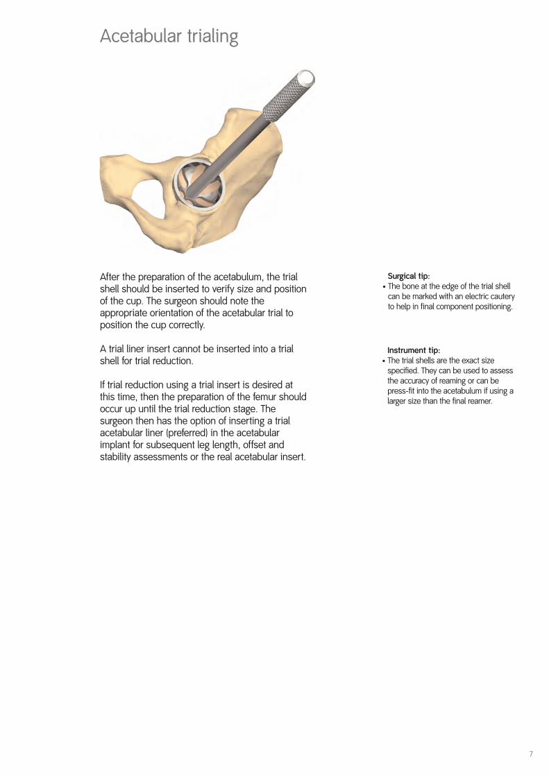
Acetabular trialing
After the preparation of the acetabulum, the trialshell should be inserted to verify size and positionof the cup. The surgeon should note theappropriate orientation of the acetabular trial toposition the cup correctly.
A trial liner insert cannot be inserted into a trialshell for trial reduction.
If trial reduction using a trial insert is desired atthis time, then the preparation of the femur shouldoccur up until the trial reduction stage. Thesurgeon then has the option of inserting a trialacetabular liner (preferred) in the acetabularimplant for subsequent leg length, offset andstability assessments or the real acetabular insert.
Surgical tip:• The bone at the edge of the trial shell
can be marked with an electric cautery to help in final component positioning.
Instrument tip:• The trial shells are the exact size
specified. They can be used to assess the accuracy of reaming or can be press-fit into the acetabulum if using a larger size than the final reamer.

Acetabular shell insertion
Select the appropriate acetabular implant, attachthe shell to the cup positioner/impactor and insertit into the acetabulum.
Rotate the X-bar shaft so that it is in line with theliner removal slot. For the THREE HOLE cup thispositions the three holes in the superior direction.
Position the X-bar so that the vertical bar isperpendicular to the long axis of the body and theappropriate crossbar (left or right) aligns with thelong axis of the body.
Firmly tap the inserter with a mallet until the cupis fully seated.
Gently toggle the impactor handle to assess thestability and contact of the shell.
Remove the X-bar, then disengage the impactorhandle and look through the impactor hole tojudge the distance between the medial wall andthe shell.
If the cup is firmly seated, there should be no gapbetween the shell and the medial wall and noapparent movement in the component.
Surgical tips:• The change in pitch that occurs as the
shell is seated against the medial wall is often audible. A depth gauge can be inserted through the screw holes and apex hole to determine the adequacy of shell seating.
• The use of the slap hammer may be helpful in extracting the shell for repositioning.
Instrument tips:• The plastic tip on the cup impactor is
removable for cleaning.
• The X-bar references 45° of abductionand 20° of anterversion.
8
Specific to shells for R3™ acetabular ceramicliners: Proper range of motion is critical for implantlongevity. If any repositioning of the shell isrequired, it should only be performed using theshell positioner. Any use of a punch, osteotomeor other instrument on the shell’s rim could resultin damage to the taper section and compromisethe integrity of the shell and ceramic liner matingand lead to liner fracture. It is important to protectthe shell’s rim and inner taper from any damageduring implantation.

9
Acetabular screw insertion
Screw fixation is simple, fast and the mostcommon method of assuring additional fixation.Acetabular screws work in compression,which allows the shell to fully seat in theacetabular cavity.
For screw fixation, each screw hole must bepredrilled. Using the variable angle drill guide,adjust the angle of the tip to align with theselected screw hole and press firmly in the shell.After drilling the hole, use the depth gauge toverify appropriate screw length(s).
Use the screw forceps to hold the screw. Attachthe ball-joint or flexible screwdriver shaft to theend of the screw. Then introduce the screw intothe hole and screw it into place using theratcheting screwdriver handle. Make sure thescrew is fully seated within the screw hole so thatit will not impinge on the acetabular shell/liner.
Surgical tip:• Screws have been shown to be a reliable
method of assuring fixation; however, it is important to avoid neurovascular complications by proper screw placement, avoiding the anterior/superioror anterior/inferior quadrants.

10
Instrument tips: • The liner trials are designed with flexible
locking tabs around the periphery that is a quick-snap design. The trial liners are removed with the trial liner removal tool via the removal slot at the apex of the trial liner and a clockwise twist of the removal tool.
R3™ Acetabular Liner insertion
A trial reduction should be performed with thefinal shell and broach in place to appropriatelyassess head length, stem offset, liner style andposition. Use of ‘skirted’ modular heads should beavoided when possible to maximize range ofmotion to impingement.
Before inserting the R3 acetabular liner, lavageany unused holes and insert the hole covers.Using the angled hole cover inserter, place screwhole covers over any remaining screw holes andthen impact with the peg impactor. Cover theapex hole with the threaded hole cover. Using thestraight screwdriver, screw in the hole cover untilit stops and is flush with the inner diameter of theshell. Insert heard bearings only after ensuringthe inner taper of the shell is clean and dry.
For liner insertion, screw the appropriate sizedliner impactor head on the end of the cupimpactor handle and ensure that the tabs on the liner are aligned with the indentions in theshell. Impact firmly with the mallet until the liner is fully seated.
Inspect the liner/shell interface for proper seating.The liner should sit flush with the face of the shell.
Surgical tips:• Running a finger around the
circumference of the shell and a visual check will help determine if the liner is flush with the shell face.
• The XLPE liner requires an impaction force between 60 and 120 pounds, increasing with the diameter of the shell.
• The XLPE & CoCr liners can be removedand repositioned once without compromising the locking mechanism ofthe liner. To remove R3 liners, insert the liner removal tool fully into the removal slot and pry the liner loose.

11
R3™ Acetabular Liner insertion continued
R3 Hard Bearing Insertion
R3 Hard Bearings come preassembled with adisposable single-use hard bearing alignmentguide. The liner/alignment guide assembly is thenintroduced by hand and sits flush on the face ofthe shell. The liner must be checked for properorientation. Verification of proper liner seating inthe shell should be confirmed by both a visualcheck to see that the insertion ring is sitting onthe shell face and a manual check with thefingers to feel that the ring does not rock on theface of the shell. Do not impact the liner if it is notoriented properly, as this can damage the shelland/or locking mechanism. Once orientation hasbeen confirmed, impact the liner into place usingthe appropriate sized liner impactor head placedon the shell positioner/impactor. Once impacted,the alignment guide will disengage onto the shellpositioner/impactor and should be removed atthat time.*
In the event that the hard bearing alignment guideis disengaged from the liner, the alignment guideshould be reassembled to the liner beforeimplantation. This is accomplished by taking thedisposable alignment guide and placing it upsidedown on the back table. The liner can then beplaced upside down on the alignment guide suchthat the peripheral rim is sitting on the alignmentguide. Simply push the liner onto the guide untilthe insertion ring locks snugly on the liner. Theassembly is ready for placement in the shell.
Surgical tip:• It may prove helpful to rotate the
liner/guide slightly to ensure soft tissuesand osteophytes are clear.
• The metal liner can be removed byplacing the liner removal tool in theremoval slot and prying, or impactingand prying if necessary, the liner loose.
*Cautionary Statement Be sure to remove the disposable hard bearingalignment guide. It is not intended for implantation.

12
R3™ AcetabularLiner insertion continued
Specific to R3™ metal liners
The R3 metal liner and R3 shell must be used witheither Smith & Nephew BHR™ resurfacing femoralheads or Smith & Nephew BHR Modular heads.Do not mix the CoCr head or liners with any othermanufacturer’s acetabular shell or stemrespectively. Use the appropriate size head andliner only. A sizing mismatch may result inpremature implant failure.
Specific to R3™ ceramic liners
Use extreme care in handling and storage ofceramic implant components. Damage tocomponents may induce internal stresses that arenot obvious to the observer, and it may lead topremature failure of the component. Before use ofceramic implants, carefully examine eachcomponent for indications of damage that mayhave occurred during shipping or prior in-hospitalhandling. All surfaces should be smooth withoutpitting, scratches or other surface irregularities.
Only Smith & Nephew ceramic femoral heads canbe used with the R3 ceramic acetabular liners. Donot mix the ceramic liner or ceramic head withany other manufacturer’s acetabular shell or stem,respectively. Use the appropriate size head andliner only. A sizing mismatch may result inpremature implant failure. Once the liner or thehead are impacted, the ridges machined into themetal taper deform. If, for any reason, the ceramicfemoral head is removed, the metal stem tapercannot be reused with a ceramic component. Ifthe R3 ceramic liner is removed, a new R3ceramic liner must be used.
Surgical tips:
• Should a correction or revision of a R3 ceramic liner be necessary, a new R3 ceramic insert must be used.
• The ceramic liner can be removed by placing the liner removal tool in the removal slot and prying (or impacting if necessary) the liner loose.

13
Hard bearing liner insertion
1
2
3
4

14
cups
40
42
44
46
48
50
52
54
56
58
60
62
64
66/68
Metal
38 40 42 44 46 48 50 52 54
Ceramic
32 36
XLPE
22 28 32 36
REFLECTION™ Hip System
22mm 28mm 32mm 36mm
0º 143º 142º 145º 148º
20º 122º 122º 126º 128º
Ceramic — 136º 141º —
R3™ Acetabular System
22mm 28mm 32mm 36mm
0º 140º 150º 154º 157º
20º 132º 134º 136º 138º
Ceramic — — 154º 156º
Shell and liner offerings
Range of motion (SPECTRON™ stem (size 3), +4 head offset)

15
Shell OD Poly ID
PolyThicknessTaper Region mm
PolyThickness LoadBearing Region mm
40 22 5.5 6.1
42 22 6.5 7.1
44 22 7.5 8.1
46 28 5.4 6.1
48 28 6.4 7.1
48 32 4.3 5.1
50 28 7.3 8.1
50 32 5.3 6.1
52 28 8.3 9.1
52 32 6.3 7.1
52 36 4.3 5.1
54 28 9.3 10.1
54 32 7.3 8.1
54 36 5.3 6.1
56 28 10.3 11.1
56 32 8.3 9.1
56 36 6.3 7.1
58 28 11.3 12.1
58 32 9.3 10.1
58 36 7.3 8.1
60 28 12.3 13.1
60 32 10.3 11.1
60 36 8.3 9.1
62 32 11.3 12.1
62 36 9.3 10.1
64 36 10.3 11.1
66–68 36 11.3 12.1
Poly thickness chart
Taperregion
Loadbearing

16
Catalog
R3™ NO HOLE Acetabular ShellsStandard size shells Small size shellsCat. no. ODmm Cat. no. ODmm7133-1846 46 7133-1840 407133-1848 48 7133-1842 427133-1850 50 7133-1844 447133-1852 527133-1854 54 Large shell sizes7133-1856 56 7133-1866 667133-1858 58 7133-1868 687133-1860 607133-1862 627133-1864 64
R3 NO HOLE HA Acetabular ShellsStandard size shells Small size shellsCat. no. ODmm Cat. no. ODmm7133-2246 46 7133-2240 407133-2248 48 7133-2242 427133-2250 50 7133-2244 447133-2252 527133-2254 54 Large shell sizes7133-2256 56 7133-2266 667133-2258 58 7133-2268 687133-2260 607133-2262 627133-2264 64
R3 THREE HOLE Acetabular ShellsStandard size shells Small size shellsCat. no. ODmm Cat. no. ODmm7133-5546 46 7133-5540 407133-5548 48 7133-5542 427133-5550 50 7133-5544 447133-5552 527133-5554 54 Large shell sizes7133-5556 56 7133-5566 667133-5558 58 7133-5568 687133-5560 607133-5562 627133-5564 64
R3 THREE HOLE HA Acetabular ShellsStandard size shells Small size shellsCat. no. ODmm Cat. no. ODmm7133-1946 46 7133-1940 407133-1948 48 7133-1942 427133-1950 50 7133-1944 447133-1952 527133-1954 54 Large shell sizes7133-1956 56 7133-1966 667133-1958 58 7133-1968 687133-1960 607133-1962 627133-1964 64
17
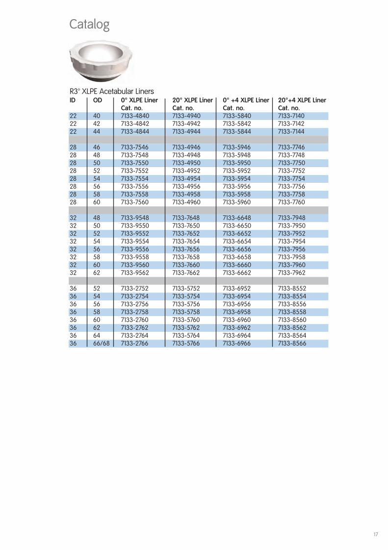
R3™ XLPE Acetabular LinersID OD 0° XLPE Liner 20° XLPE Liner 0° +4 XLPE Liner 20°+4 XLPE Liner
Cat. no. Cat. no. Cat. no. Cat. no.22 40 7133-4840 7133-4940 7133-5840 7133-714022 42 7133-4842 7133-4942 7133-5842 7133-714222 44 7133-4844 7133-4944 7133-5844 7133-7144
28 46 7133-7546 7133-4946 7133-5946 7133-774628 48 7133-7548 7133-4948 7133-5948 7133-774828 50 7133-7550 7133-4950 7133-5950 7133-775028 52 7133-7552 7133-4952 7133-5952 7133-775228 54 7133-7554 7133-4954 7133-5954 7133-775428 56 7133-7556 7133-4956 7133-5956 7133-775628 58 7133-7558 7133-4958 7133-5958 7133-775828 60 7133-7560 7133-4960 7133-5960 7133-7760
32 48 7133-9548 7133-7648 7133-6648 7133-794832 50 7133-9550 7133-7650 7133-6650 7133-795032 52 7133-9552 7133-7652 7133-6652 7133-795232 54 7133-9554 7133-7654 7133-6654 7133-795432 56 7133-9556 7133-7656 7133-6656 7133-795632 58 7133-9558 7133-7658 7133-6658 7133-795832 60 7133-9560 7133-7660 7133-6660 7133-796032 62 7133-9562 7133-7662 7133-6662 7133-7962
36 52 7133-2752 7133-5752 7133-6952 7133-855236 54 7133-2754 7133-5754 7133-6954 7133-855436 56 7133-2756 7133-5756 7133-6956 7133-855636 58 7133-2758 7133-5758 7133-6958 7133-855836 60 7133-2760 7133-5760 7133-6960 7133-856036 62 7133-2762 7133-5762 7133-6962 7133-856236 64 7133-2764 7133-5764 7133-6964 7133-856436 66/68 7133-2766 7133-5766 7133-6966 7133-8566
Catalog
18
Catalog
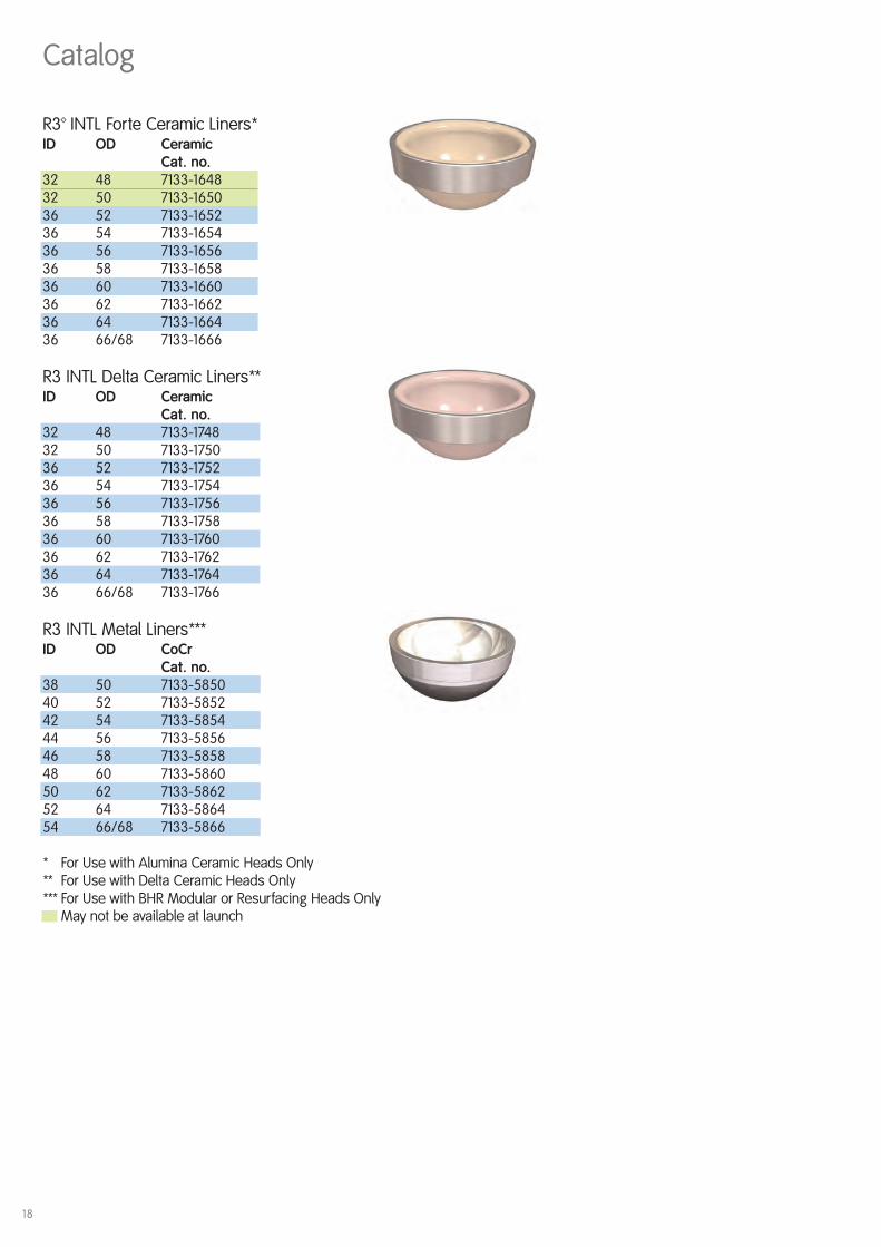
R3™ INTL Forte Ceramic Liners*ID OD Ceramic
Cat. no.32 48 7133-164832 50 7133-165036 52 7133-165236 54 7133-165436 56 7133-165636 58 7133-165836 60 7133-166036 62 7133-166236 64 7133-166436 66/68 7133-1666
R3 INTL Delta Ceramic Liners**ID OD Ceramic
Cat. no.32 48 7133-174832 50 7133-175036 52 7133-175236 54 7133-175436 56 7133-175636 58 7133-175836 60 7133-176036 62 7133-176236 64 7133-176436 66/68 7133-1766
R3 INTL Metal Liners***ID OD CoCr
Cat. no.38 50 7133-585040 52 7133-585242 54 7133-585444 56 7133-585646 58 7133-585848 60 7133-586050 62 7133-586252 64 7133-586454 66/68 7133-5866
* For Use with Alumina Ceramic Heads Only** For Use with Delta Ceramic Heads Only*** For Use with BHR Modular or Resurfacing Heads Only
May not be available at launch

19
Catalog
R3 Poly Snap in Trial LinersID OD 0° Trial 20° Trial 0° +4 Trial 20°+4 Trial
Cat. no. Cat. no. Cat. no. Cat. no.22 40 7136-0540 7136-5340 7136-6140 7136-864022 42 7136-0542 7136-5342 7136-6142 7136-864222 44 7136-0544 7136-5344 7136-6144 7136-8644
28 46 7136-0546 7136-6446 7136-8346 7136-874628 48 7136-0548 7136-6448 7136-8348 7136-874828 50 7136-0550 7136-6450 7136-8350 7136-875028 52 7136-0552 7136-6452 7136-8352 7136-875228 54 7136-0554 7136-6454 7136-8354 7136-875428 56 7136-0556 7136-6456 7136-8356 7136-875628 58 7136-0558 7136-6458 7136-8358 7136-875828 60 7136-0560 7136-6460 7136-8360 7136-8760
32 48 7136-5148 7136-6548 7136-8448 7136-884832 50 7136-5150 7136-6550 7136-8450 7136-885032 52 7136-5152 7136-6552 7136-8452 7136-885232 54 7136-5154 7136-6554 7136-8454 7136-885432 56 7136-5156 7136-6556 7136-8456 7136-885632 58 7136-5158 7136-6558 7136-8458 7136-885832 60 7136-5160 7136-6560 7136-8460 7136-886032 62 7136-5162 7136-6562 7136-8462 7136-8862
36 52 7136-5252 7136-7952 7136-8552 7136-915236 54 7136-5254 7136-7954 7136-8554 7136-915436 56 7136-5256 7136-7956 7136-8556 7136-915636 58 7136-5258 7136-7958 7136-8558 7136-915836 60 7136-5260 7136-7960 7136-8560 7136-916036 62 7136-5262 7136-7962 7136-8562 7136-916236 64 7136-5264 7136-7964 7136-8564 7136-916436 66/68 7136-5266 7136-7966 7136-8566 7136-9166
R3™ Trial ShellsStandard size trail shells Small size trial shellsCat. no. ODmm Cat. no. ODmm7136-0745 45 7136-0739 397136-0746 46 7136-0740 407136-0747 47 7136-0741 417136-0748 48 7136-0742 427136-0749 49 7136-0743 437136-0750 50 7136-0744 447136-0751 517136-0752 52 Large size trial shells7136-0753 53 Cat. no. ODmm7136-0754 54 7136-0765 657136-0755 55 7136-0766 667136-0756 56 7136-0767 677136-0757 57 7136-0768 687136-0758 587136-0759 597136-0760 607136-0761 617136-0762 627136-0763 637136-0764 64
20
Catalog
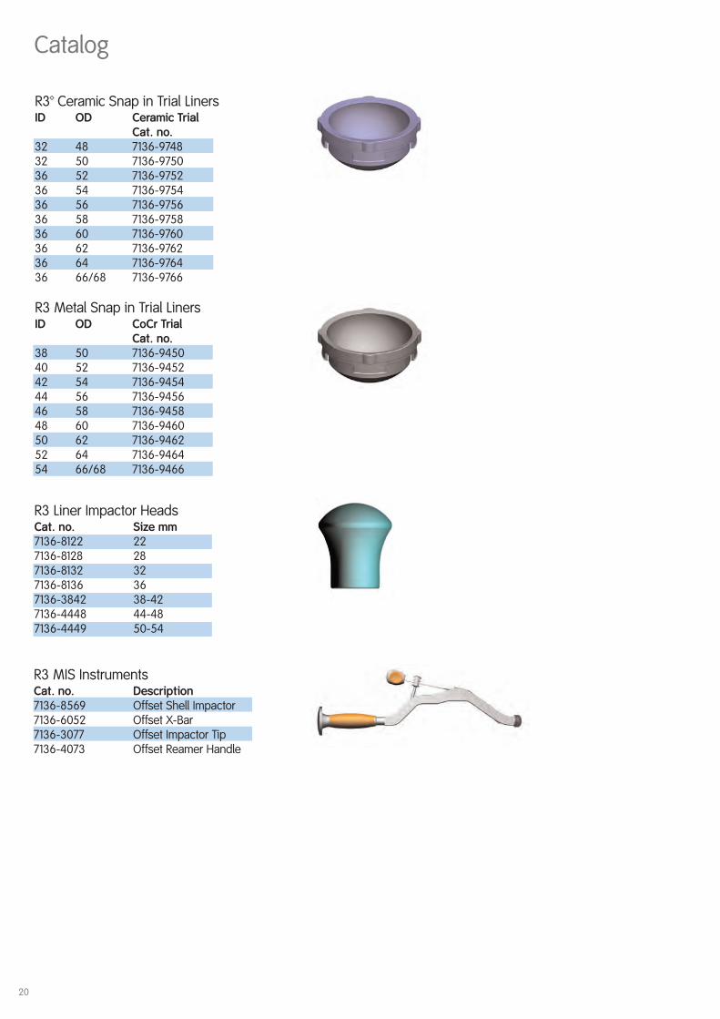
R3™ Ceramic Snap in Trial LinersID OD Ceramic Trial
Cat. no.32 48 7136-974832 50 7136-975036 52 7136-975236 54 7136-975436 56 7136-975636 58 7136-975836 60 7136-976036 62 7136-976236 64 7136-976436 66/68 7136-9766
R3 Metal Snap in Trial LinersID OD CoCr Trial
Cat. no.38 50 7136-945040 52 7136-945242 54 7136-945444 56 7136-945646 58 7136-945848 60 7136-946050 62 7136-946252 64 7136-946454 66/68 7136-9466
R3 Liner Impactor HeadsCat. no. Size mm7136-8122 227136-8128 287136-8132 327136-8136 367136-3842 38-427136-4448 44-487136-4449 50-54
R3 MIS InstrumentsCat. no. Description7136-8569 Offset Shell Impactor7136-6052 Offset X-Bar7136-3077 Offset Impactor Tip7136-4073 Offset Reamer Handle

21
Catalog
R3™ Straight Shell ImpactorCat. no. 7136-4450
R3 Impactor Replacement TipCat. no. 7136-8570
R3 Depth GuageCat. Nno. 7136-4451
X-BarCat. no. MT-2201
Screw ForcepsCat. no. 7136-2298
Ball Joint ScrewdriverCat. no. 7136-2295
R3 Variable Angle Drill GuideCat. no. 7136-4477
Reamer HandleCat. no. 7136-2279
Flexible Screw DrillsCat. no. Length mm7136-2915 157136-2925 257136-2935 357136-2950 50
Captured Flexible Screwdriver ShaftCat. no. 7136-2291
Captured U-Joint Screwdriver ShaftCat. no. 7136-2292
R3 Surgical Templates (not shown)Cat. no. 7136-1081

22
R3™ Trial Liner Removal ToolCat. no. 7136-4455
R3 Liner Removal ToolCat. no. 7136-6021
Hole Cover ImpactorCat. no. 73-2117
Trial Shell HandleCat. no. 7136-2297
Flexible ScrewdriverCat. no. 7136-2290
Ratchet HandleCat. no. 7136-2294
Small Slap HammerCat. no. 7136-7541
REFLECTION™ MalletCat. no. 7136-2106
Hole Cover InserterCat. no. 73-2133
Straight Screwdriver ShaftCat. no. 7136-2293
Power Adaptors (not shown)Cat. no. 7136-2781
7136-27827136-2783
Catalog

23
Catalog
Reamer DomesStandard size Small sizeCat. no. Size mm Cat. no. Size mm7136-2742 42 7136-2738 387136-2743 43 7136-2739 397136-2744 44 7136-2740 407136-2745 45 7136-2741 417136-2746 467136-2747 47 Large size7136-2748 48 Cat. no. Size mm7136-2749 49 7136-2765 657136-2750 50 7136-2766 667136-2751 51 7136-2767 677136-2752 52 7136-2768 687136-2753 53 7136-2769 697136-2754 54 7136-2770 707136-2755 55 7136-2771 717136-2756 56 7136-2772 727136-2757 57 7136-2773 737136-2758 58 7136-2774 747136-2759 59 7136-2775 757136-2760 60 7136-2776 767136-2761 617136-2762 627136-2763 637136-2764 64
24
Catalog
Small Outer CaseCat. no. 7112-9401
Lid for Outer CasesCat. no. 7112-9402
R3™ Trial Liner LidCat. no. 7136-1081
R3 Trial Shell TrayCat. no. 7136-2213
R3 20 Degree Trial Liner TrayCat. no. 7136-1073
R3 20 Degree +4 Trial Liner TrayCat. no. 7136-1074
R3 Metal Trial liner TrayCat. no. 7136-2220
R3 Jumbo Trial Liner Tray Cat. no. 7136-1076
R3 0 Degree Outlier TrayCat. no. 7136-1085
R3 0 Degree +4 OutlierTrayCat. no. 7136-1084
R3 Demo Sample CaseCat. no. 7138-4096
R3 Main Instrument TrayCat. no. 7136-2211
R3 MIS Instrument TrayCat. no. 7136-2219
R3 Primary Reamer Dome TrayCat. no. 7136-2212

26
Catalog
Biolox Delta 12/14 Femoral HeadsCat. no. I.D.7653-9162 32 L7653-9161 32 M7653-9160 32 S7653-9167 36 L7653-9166 36 M7653-9165 36 S
Biolox Forte 12/14 Femoral HeadsCat. no. ID 7133-3200 32 +07133-3204 32 +47133-3208 32 +87133-1047 36 +07133-1048 36 +47133-1049 36 +8
Resurfacing Femoral HeadsCat. no. ID7412-1138 387412-3140 407412-1142 427412-3144 447412-1146 467412-3148 487412-1150 507412-3152 526412-1154 54
Modular Head SleevesCat. no. mm7422-2100 -4mm7422-2200 +0mm7422-2300 +4mm7422-2400 +8mm

27
Catalog
Modular Metal Femoral HeadsCat. no. ID7422-2138 387422-2140 407422-2142 427422-2144 447422-2146 467422-2148 487422-2150 507422-2152 527422-2154 54
Modular Head TrialsCat. no. ID9003-5538 389003-5540 409003-5542 429003-5544 449003-5546 469003-5548 489003-5550 509003-5552 529003-5554 54
Trial NecksCat. no. mm9003-5571 -49003-5572 +09003-5573 +49003-5574 +8

Orthopaedic ReconstructionSmith & Nephew, Inc.1450 Brooks RoadMemphis, TN 38116USA
Telephone: 1-901-396-2121Information: 1-800-821-5700Orders/Inquiries: 1-800-238-7538
45940101 12/07
www.smith-nephew.com
™Trademark of Smith & Nephew. Certain marks Reg. US Pat. & TM Off


![COMPUTER ORGANIZATION & ARCHITECTURE · mov r3, h r3 m [h] add r3, g r3 r3+m [g] div r1, r3 r1 r1/r3 mov x, r1 m[x] r1 page 4 of 16 knreddy computer organization and architecture.](https://static.fdocuments.in/doc/165x107/6144b5c334130627ed50859a/computer-organization-architecture-mov-r3-h-r3-m-h-add-r3-g-r3-r3m-g.jpg)