R290LC-7A rev.4 (09.09) PDF (Page 1)
10
Standard Equipment Optional Equipment Air-conditioner (5,000 kcal/hr, 20,000 BTU/hr) FATC(Full Automatic Temperature Control) Sun visor for cabin inside Fuel filler pump (35 /min, 9.5 USgpm) Beacon lamp Safety lock valve for boom cylinder with overload warning device Safety lock valve for arm cylinder Single acting piping kit (breaker, etc) Double acting piping kit (cramshell, etc) Quick Coupler Accumulator, work equipment lowering 12 volt power supply (DC-DC converter) Electric. transducer Travel alarm CD Player Various optional Arms Super short arm (2.10 m, 6’ 11”) Short arm (2.50 m, 8’ 2”) Long arm (3.75 m, 12’ 4”) Various optional Buckets (SAE heaped) Standard bucket (1.27 m 3 , 1.66 yd 3 ) Narrow bucket (0.79 m 3 , 1.03 yd 3 ) Narrow bucket (1.03 m 3 , 1.35 yd 3 ) Light duty bucket (1.50 m 3 , 1.96 yd 3 ) Light duty bucket (1.73 m 3 , 2.26 yd 3 ) Light duty bucket (1.85 m 3 , 2.42 yd 3 ) Heavy duty bucket (1.07 m 3 , 1.40 yd 3 ) Heavy duty bucket (1.15 m 3 , 1.50 yd 3 ) Heavy duty bucket (1.27 m 3 , 1.66 yd 3 ) Heavy duty bucket (1.46 m 3 , 1.91 yd 3 ) Rock-Heavy duty bucket (1.16 m 3 , 1.52 yd 3 ) Rock-Heavy duty bucket (1.49 m 3 , 1.95 yd 3 ) Cabin lights Cabin FOPS/FOG(ISO/DIS 10262) Cabin Roof-cover Transparent Track shoes Triple grousers shoe (700 mm, 28”) Triple grousers shoe (800 mm, 32”) Triple grousers shoe (900 mm, 36”) Lower frame under cover Pre heating system Tool kit Operator suit Tropical Kit Fan drive ratio(1.1:1) Louver side cover(R/H) side Seat Adjustable air suspension seat Adjustable air suspension seat with heater Mechanical suspension with heater Pattern change valve (2 patterns) ISO standard cab All-weather steel cab with all-around visibility Safety glass windows Rise-up type windshield wiper Sliding fold-in front window Sliding side window Lockable door Hot & cool box Accessory box & Ash-tray Computer Aided Power Optimization (New CAPO) system 2-power mode, 3-work mode, 2-user mode Auto deceleration & one touch deceleration system Auto warm up system Auto overheat prevention system Heater(7,500 kcal/hr, 30,000BTU/hr) & Defroster Self diagnostic system Centralized monitoring LCD display Engine speed Clock & Error code Gauges Fuel level gauge Engine coolant temperature gauge Hyd. oil temperature gauge Warning Fuel level Check Engine & CPU Engine oil pressure Engine coolant temperature Hyd. oil temperature Low battery Air cleaner clogging Indicator Power boost Engine warming-up Auto(One touch) decel Preheat(Air gride heater) Removable clean out screen for oil cooler Door and cab locks, one key Two outside rearview mirrors Fully adjustable suspension seat with seat belt Slidable joystick, pilot-operated Automatic swing brake Removable reservoir tank Water separator & Fuel pre-filter, fuel line Boom holding system Arm holding system Counterweight (5200kg, 11460lb) mono boom (6.25m, 20’ 6”) Arm (3.05m, 10’ 0”) Track shoes (600mm, 23.6”) Track rail guard Am/Fm radio and USB player Remote control switch Console box tilting system (LH.) Three front working light Electric horn Batteries (2 x 12V x 160AH) Battery master switch Starting Aid(air gride heater) cold weather Fuel warmer Robex 290LC-7A *Photo may include optional equipment. CRAWLER EXCAVATOR Applied Tier 3 Engine 290LC - 7A PLEASE CONTACT www.hyundai-ce.com 2009. 09 Rev. 4 Standard and optional equipment may vary. Contact your Hyundai dealer for more information. The machine may vary according to International standards. All imperial measurements rounded off to the nearest pound or inch.
Transcript of R290LC-7A rev.4 (09.09) PDF (Page 1)

Standard Equipment Optional Equipment
Air-conditioner (5,000 kcal/hr, 20,000 BTU/hr)FATC(Full Automatic Temperature Control)Sun visor for cabin insideFuel filler pump (35 /min, 9.5 USgpm) Beacon lampSafety lock valve for boom cylinder with
overload warning deviceSafety lock valve for arm cylinderSingle acting piping kit (breaker, etc)Double acting piping kit (cramshell, etc)Quick CouplerAccumulator, work equipment lowering12 volt power supply (DC-DC converter)Electric. transducerTravel alarmCD Player
Various optional ArmsSuper short arm (2.10 m, 6’ 11”)Short arm (2.50 m, 8’ 2”)Long arm (3.75 m, 12’ 4”)
Various optional Buckets (SAE heaped)Standard bucket (1.27 m3, 1.66 yd3)Narrow bucket (0.79 m3, 1.03 yd3)Narrow bucket (1.03 m3, 1.35 yd3)Light duty bucket (1.50 m3, 1.96 yd3)Light duty bucket (1.73 m3, 2.26 yd3)Light duty bucket (1.85 m3, 2.42 yd3)Heavy duty bucket (1.07 m3, 1.40 yd3)Heavy duty bucket (1.15 m3, 1.50 yd3)Heavy duty bucket (1.27 m3, 1.66 yd3)Heavy duty bucket (1.46 m3, 1.91 yd3)Rock-Heavy duty bucket (1.16 m3, 1.52 yd3)Rock-Heavy duty bucket (1.49 m3, 1.95 yd3)
Cabin lightsCabin FOPS/FOG(ISO/DIS 10262)Cabin Roof-cover TransparentTrack shoes
Triple grousers shoe (700 mm, 28”)Triple grousers shoe (800 mm, 32”)Triple grousers shoe (900 mm, 36”)
Lower frame under coverPre heating systemTool kitOperator suitTropical Kit
Fan drive ratio(1.1:1)Louver side cover(R/H) side
Seat Adjustable air suspension seatAdjustable air suspension seat with heaterMechanical suspension with heater
Pattern change valve (2 patterns)
ISO standard cabAll-weather steel cab with all-around visibilitySafety glass windowsRise-up type windshield wiperSliding fold-in front windowSliding side windowLockable doorHot & cool boxAccessory box & Ash-tray
Computer Aided Power Optimization(New CAPO) system
2-power mode, 3-work mode, 2-user modeAuto deceleration & one touch deceleration systemAuto warm up systemAuto overheat prevention system
Heater(7,500 kcal/hr, 30,000BTU/hr) & DefrosterSelf diagnostic systemCentralized monitoring
LCD displayEngine speedClock & Error codeGaugesFuel level gaugeEngine coolant temperature gaugeHyd. oil temperature gaugeWarningFuel levelCheck Engine & CPUEngine oil pressureEngine coolant temperatureHyd. oil temperature Low batteryAir cleaner cloggingIndicatorPower boostEngine warming-upAuto(One touch) decelPreheat(Air gride heater)
Removable clean out screen for oil coolerDoor and cab locks, one keyTwo outside rearview mirrorsFully adjustable suspension seat with seat beltSlidable joystick, pilot-operatedAutomatic swing brakeRemovable reservoir tankWater separator & Fuel pre-filter, fuel lineBoom holding systemArm holding systemCounterweight (5200kg, 11460lb)mono boom (6.25m, 20’ 6”)Arm (3.05m, 10’ 0”)Track shoes (600mm, 23.6”)Track rail guardAm/Fm radio and USB player
Remote control switchConsole box tilting system (LH.)Three front working lightElectric hornBatteries (2 x 12V x 160AH)Battery master switchStarting Aid(air gride heater) cold weatherFuel warmer
Robex 290LC-7A
*Photo may include optional equipment.
CRAWLER EXCAVATOR Applied Tier 3 Engine
290LC-7A
PLEASE CONTACT
www.hyundai-ce.com 2009. 09 Rev. 4
Standard and optional equipment may vary. Contact your Hyundai dealer for more information. The machine may vary according to International standards.All imperial measurements rounded off to the nearest pound or inch.
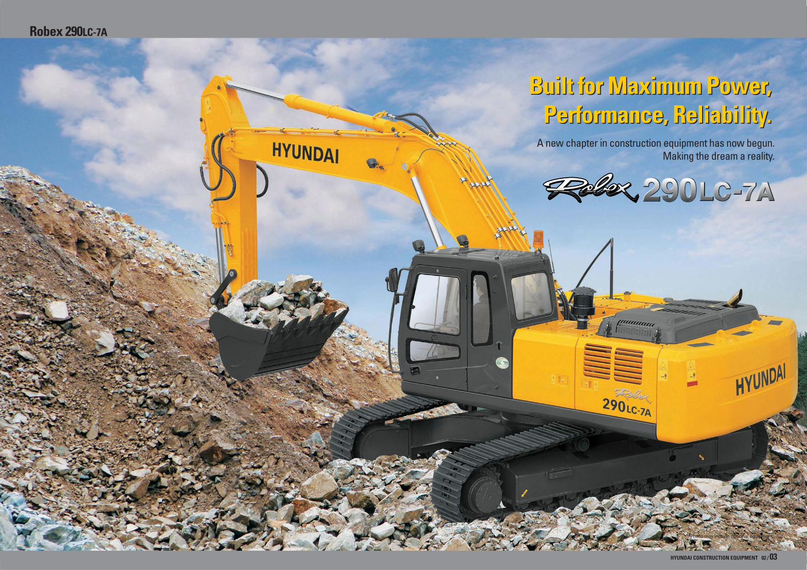
Built for Maximum Power, Performance, Reliability.
Built for Maximum Power, Performance, Reliability.
A new chapter in construction equipment has now begun. Making the dream a reality.
HYUNDAI CONSTRUCTION EQUIPMENT 02 / 03
*Photo may include optional equipment.
Robex 290LC-7A
HYUNDAI CONSTRUCTION EQUIPMENT 04 / 05
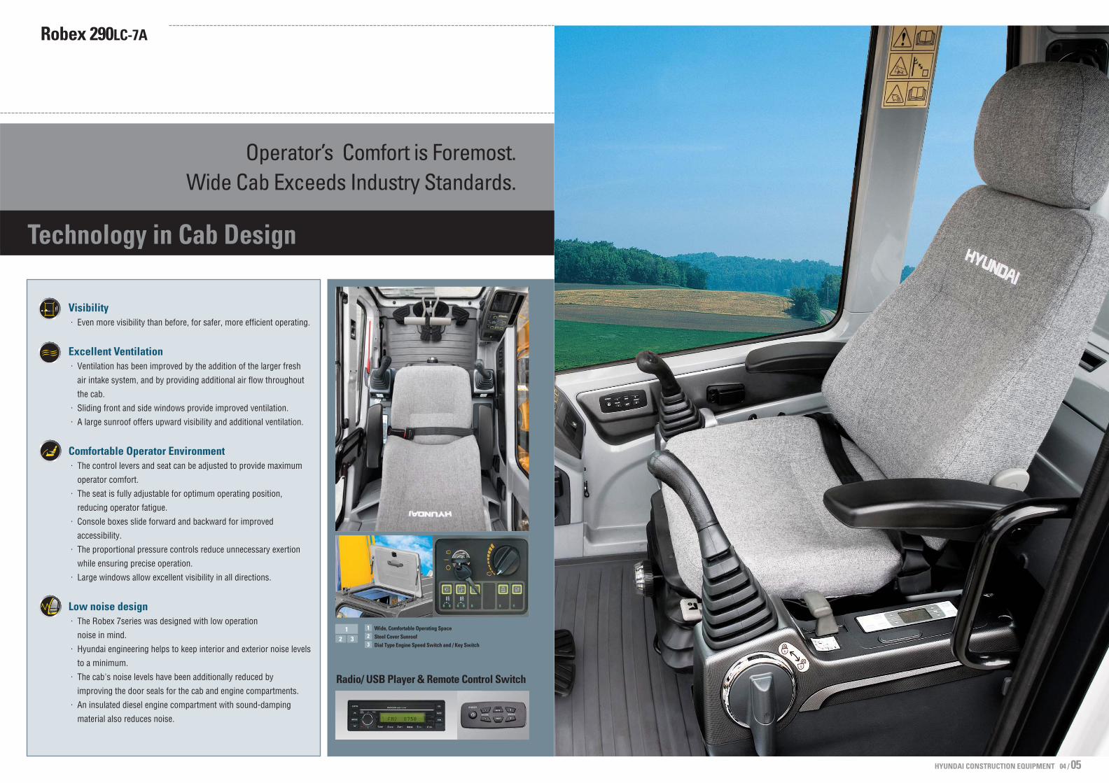
Technology in Cab Design
Operator’s Comfort is Foremost.Wide Cab Exceeds Industry Standards.
Visibility. Even more visibility than before, for safer, more efficient operating.
Excellent Ventilation. Ventilation has been improved by the addition of the larger fresh
air intake system, and by providing additional air flow throughout
the cab.. Sliding front and side windows provide improved ventilation.. A large sunroof offers upward visibility and additional ventilation.
Comfortable Operator Environment. The control levers and seat can be adjusted to provide maximum
operator comfort. . The seat is fully adjustable for optimum operating position,
reducing operator fatigue. . Console boxes slide forward and backward for improved
accessibility. . The proportional pressure controls reduce unnecessary exertion
while ensuring precise operation.. Large windows allow excellent visibility in all directions.
Low noise design. The Robex 7series was designed with low operation
noise in mind.. Hyundai engineering helps to keep interior and exterior noise levels
to a minimum. . The cab's noise levels have been additionally reduced by
improving the door seals for the cab and engine compartments. . An insulated diesel engine compartment with sound-damping
material also reduces noise.
12 3
Wide, Comfortable Operating SpaceSteel Cover SunroofDial Type Engine Speed Switch and / Key Switch
123
Radio/ USB Player & Remote Control Switch
Robex 290LC-7A

Operating Environment
Highly Sensitive Joystickand Easy EntranceNew joystick grips for precisecontrol have been equipped with4 switches.
Easy-to-Reach ControlPanelsSwitches and other essentialcontrols are located near theoperator. This helps keep operator move-ment to a minimum, enhancingcontrol with less operatorfatigue.
Rear Emergency ExitWindowRear Exit Window is designedwith easy exit for operator'ssafety.
Raise-up Wiper and CabinLightsRaise-up wiper has enhanced forthe better front view. Cabin Lightsenhances safety by brightlylighting the surroundings duringnight work(optional)Left
Right Horn/Optional/Dummy
Power boost One touch decelerationDummy
Smooth Travel Pedal and Foot Rests
Wide Cab with Excellent VisibilityThe cab is roomy and ergonomically designed with low noise leveland good visibility. A full view front window and large rear and sidewindows provide excellent visibility in all directions.
Minimization of Shock and Vibration through CabMounting SystemThe application of Viscous Mounting to the cabin support provides theoperator with a much improved ride. The operator work efficiency willincrease as the shock and noise level in the cabin decreases.
Improved Intelligent DisplayInstrument Panel is installed in front of RHconsole box. It is easy to check all critical systems witheasy-to-read indicators.
Storage box and Cup HolderAn Additional storage box and cup holder are locatedbehind operator’s seat, and it keeps food andbeverages cool or hot.
Wide, Comfortable Operating SpaceAll the controls are designed and positionedaccording to the latest ergonomic research.Reinforced pillars have also been added forgreater cab rigidity.
HYUNDAI CONSTRUCTION EQUIPMENT 06 / 07
CAB
CAB
Centralized control panel
Horn button
Option button
Remote Radio control
Travel lever
Cluster
One touch decel button
Hour meter
Travel pedal
Fully adjustable suspension seat
Safety lever
Power boost button
Joystick control lever
Air Conditioner and Heater controller
The best working conditions in a pleasant environment.
Robex 290LC-7A
Maximum Protection
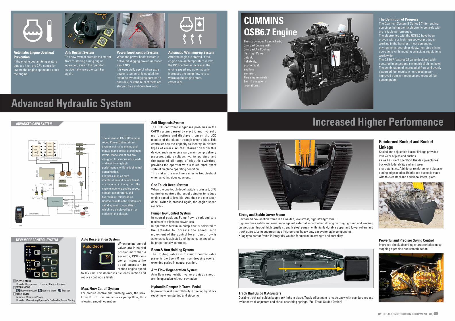
The six cylinder 4 cycle TurboCharged Engine withCharged Air Cooling,Has High Poweroutput,Reliability,economical,and lowemission.This engine meetsTier III emissionsregulations.
CUMMINS QSB6.7 Engine
The Definition of ProgressThe Quantum System B Series 6.7-liter enginecombines full-authority electronic controls withthe reliable performance.The electronics with the QSB6.7 have beenproven with our high-horsepower products-working in the harshest, most demandingenvironments-search as dusty, non-stop miningoperations while meeting emissions regulationsworldwide.The QSB6.7 features 24 valve designed withcentered injectors and symmetrical piston bowl. The combination of improved airflow and evenlydispersed fuel results in increased power,improved transient reponse and reduced fuelconsumption.
Track Rail Guide & AdjustersDurable track rail guides keep track links in place. Track adjustment is made easy with standard greasecylinder track adjusters and shock absorbing springs. (Full Track Guide : Option)
Strong and Stable Lower FrameReinforced box-section frame is all welded, low-stress, high-strength steel. It guarantees safety and resistance against external impact when driving on rough ground and workingon wet sites through high tensile strength steel panels, with highly durable upper and lower rollers andtrack guards. Long undercarriage incorporates heavy duty excavator style components.X-leg type center frame is integrally welded for maximum strength and durability.
Powerful and Preciser Swing ControlImproved shock absorbing characteristics makestopping a precise and smooth action
Reinforced Bucket and BucketLinkageSealed and adjustable bucket linkage providesless wear of pins and bushes as well as silent operation.The design includesbucket link durability and anti wearcharacteristics. Additional reinforcement plates oncutting edge section. Reinforced bucket is madewith thicker steel and additional lateral plate.
Self Diagnosis SystemThe CPU controller diagnoses problems in theCAPO system caused by electric and hydraulicmalfunctions and displays them on the LCDmonitor of the cluster through error codes. Thiscontroller has the capacity to identify 48 distincttypes of errors. As the information from thisdevice, such as engine rpm, main pump deliverypressure, battery voltage, hyd. temperature, andthe state of all types of electric switches,provides the operator with a much more exactstate of machine operating condition. This makes the machine easier to troubleshootwhen anything does go wrong.
One Touch Decel SystemWhen the one touch decel switch is pressed, CPUcontroller controls the accel actuator to reduceengine speed to low idle. And then the one touchdecel switch is pressed again, the engine speedrecovers.
Pump Flow Control SystemIn neutral position: Pump flow is reduced to aminimum to eliminate power loss. In operation: Maximum pump flow is delivered tothe actuator to increase the speed. Withmovement of the control lever, pump flow isautomatically adjusted and the actuator speed canbe proportionally controlled.
Boom & Arm Holding System The Holding valves in the main control valveprevents the boom & arm from dropping over anextended period in neutral position.
Arm Flow Regeneration SystemArm flow regeneration valve provides smootharm-in operation without cavitation.
Hydraulic Damper in Travel PedalImproved travel controllability & feeling by shockreducing when starting and stopping.
Auto Deceleration SystemWhen remote-controlvalves are in neutralposition more than 4seconds, CPU con-troller instructs theaccel actuator toreduce engine speed
to 1050rpm. This decreases fuel consumption andreduces cab noise levels.
Max. Flow Cut-off SystemFor precise control and finishing work, the Max.Flow Cut-off System reduces pump flow, thusallowing smooth operation.
ADVANCED CAPO SYSTEM
NEW MODE CONTROL SYSTEM
Power boost control SystemWhen the power boost system isactivated, digging power increasesabout 10%. It is especially useful when extrapower is temporarily needed, forinstance, when digging hard earthand rock, or if the bucket teeth arestopped by a stubborn tree root.
Automatic Engine OverheatPreventionIf the engine coolant temperaturegets too high, the CPU controllerlowers the engine speed and coolsthe engine.
Automatic Warming-up SystemAfter the engine is started, if theengine coolant temperature is low,the CPU controller increases theengine speed and automaticallyincreases the pump flow rate towarm up the engine more effectively.
Anti Restart SystemThe new system protects the starterfrom re-starting during engineoperation, even if the operatoraccidentally turns the start key again.
Advanced Hydraulic System
Increased Higher PerformanceThe advanced CAPO(ComputerAided Power Optimization)system maintains engine andmutual pump power at optimumlevels. Mode selections aredesigned for various work loadsand maintaining highperformance while reducing fuelconsumption. Features such as autodeceleration and power boostare included in the system. Thesystem monitors engine speed,coolant temperature, andhydraulic oil temperature.Contained within the system areself diagnostic capabilitieswhich are displayed by errorcodes on the cluster.
POWER MODEH mode: High power S mode: Standard powerWORK MODE
Heavy duty work General work BreakerUSER MODEM mode: Maximum PowerU mode : Memorizing Operator’s Preferable Power Setting
1
2
3
12
3
HYUNDAI CONSTRUCTION EQUIPMENT 08 / 09

Reliability & Serviceability
Centralized Electric Control Box andEasy Change Air Cleaner AssemblyElectric control box and Air cleaner are centralized in one or the samecompartment for easy service.
Highly efficient Hydraulic PumpPump output capacity has been increased.
Large tool box for extra storage
Full open doors and master key systemprovide easy access for servicing.
Side Cover with Left & Right Swing Open TypeEasy access to vital components gives unrestricted view ofcomponent allows easy maintenance and repair.
Easy to maintain engine componentsThe cooling and preheating system are provided for optimum andimmediate operation, guaranteeing longer life for the engine andhydraulic components. Servicing of the engine and hydraulics is considerably simplifieddue to total accessibility.
Durability of structure proven throughFEM(Finite Element Method) analysisand long term durability test.
HYUNDAI CONSTRUCTION EQUIPMENT 10 / 11
Robex 290LC-7A
*Photo may include optional equipment.

HYUNDAI CONSTRUCTION EQUIPMENT 12 / 13
Specifications Backhoe attachment
Engine
Watercooled, 4 cycle Diesel,6-Cylindersin line, direct injection,Turbo charged,charger air cooled and low emission
227 HP (169 kW) at 1,900 rpm197 HP (147 kW) at 1,900 rpm230 PS (169 kW) at 1,900 rpm200 PS (147 kW) at 1,900 rpm96.8 kgf.m(700 lbf.ft) at 1,400 rpm107 x 124 mm (4.2” x 4.9”)6,700 cc (409 cu in)2 x 12 V x 160 AH24 V, 4.5kW24 V, 50 Amp
Type
Ratedflywheelhorsepower
Max. torqueBore x strokePiston displacementBatteriesStarting motorAlternator
J1995 (gross)J1349 (net)6271/1 (gross)6271/1 (net)
SAE
DIN
Buckets
Arms
Model Cummins QSB6.7
Swing system
Swing motorSwing reductionSwing bearing lubricationSwing brakeSwing speed
Axial piston motorPlanetary gear reductionGrease-bathedmulti wet disc10.2 rpm
Coolant & Lubricant capacity
(refilling)Fuel tankEngine coolant Engine oilSwing deviceFinal drive(each)Hydraulic system(including tank)Hydraulic tank
liter48050.0
2411.05.5
320.0210.0
US gal126.813.26.31.82.9
84.555.5
UK gal105.611.05.31.52.4
70.446.2
Undercarriage
Center frameTrack frameNo. of shoes on each sideNo. of carrier roller on each sideNo. of track roller on each sideNo. of rail guides on each side
X - leg typePentagonal box type48292
Drives & Brakes
Drive methodDrive motorReduction systemMax. drawbar pullMax. travel speed(high) / (low)GradeabilityParking brake
Pilot pressure operated joysticks and pedals with detachable leverprovide almost effortless and fatigueless operation.
X-leg type center frame is integrally welded with reinforced box-section track frames. The undercarriage includes lubricated rollers,idlers, track adjusters with shock absorbing spring and sprocket,assembled trak chain with triple grouser shoes.
Operating weight (approximate)
Major component weight7,040 kg (15,520 lb)5,200 kg (11,460 lb)2,670 kg (5,900 lb)
UpperstructureCounterweightBoom (with arm cylinder)
Operating weight
Operating weight, including 6.25 m (20’ 6”) boom, 3.05 m (10’ 0”) arm,SAE heaped 1.27 m3 (1.66 yd3) backhoe bucket, lubricant, coolant, fullfuel tank, hydraulic tank and the standard equipment.
Hydraulic system
Two variable displacement piston pumps2x252 /min (68.7 US gpm / 57.2 UK gpm)Gear pump
Two speed axial piston motorwith brake valve and parking brake
Axial piston motor with automatic brake
330 kgf/cm2 (4690 psi)330 kgf/cm2 (4690 psi)360 kgf/cm2 (5120 psi)265 kgf/cm2 (3770 psi)35 kgf/cm2 (498 psi)Installed
Boom: 2-140 1465 mm (5.5” 57.7”)Arm: 1-150 1765 mm (5.9” 69.5”)Bucket: 1-140 1185 mm (5.5” 46.7”)
TypeMax. flowSub-pump for pilot circuitCross-sensing and fuel saving pump system
Travel
Swing
Implement circuitsTravelPower boost (boom, arm, bucket)Swing circuitPilot circuitService valve
No. of cylinder-bore x stroke
Main pump
Hydraulic motors
Relief valve setting
Hydraulic cylinders
Fully hydrostatic typeAxial piston motor, in-shoe designPlanetary reduction gear27,300 kgf (60,200 lbf)5.2 km/hr (3.2 mph) / 3.1 km/hr (1.9 mph)35 (70 %)multi wet disc
Traveling and steeringEngine throttleExternal Lights
Pilot control Two joysticks with one safety lever(LH): Swing and arm, (RH): Boom and bucket(ISO)
Two levers with pedalsElectric, Dial typeTwo lights mounted on the boom one under the battery box
Control
Standard equipment
SAE heaped 3750(12’ 4”)
3050(10’ 0”)
2500(8’ 2”)
2100(6’ 11”)Arm
Weight kg(lb)Width mm (in)
Boom
CECE heaped Without side cutters With side cutters
Capacity m3 (yd3)Recommendation mm(ft.in)
: Standard backhoe bucket: Heavy-duty : Rock-Heavy duty bucket
: Applicable for materials with density of 2,000 kg / m3 (3,370 lb/ yd3) or less: Applicable for materials with density of 1,600 kg / m3 (2,700 lb/ yd3) or less: Applicable for materials with density of 1,100 kg / m3 (1,850 lb/ yd3) or less
6250 (20’ 6”)
0.79 (1.03)1.03 (1.35)1.27 (1.66)1.50 (1.96)1.73 (2.26)1.85 (2.42)1.07 (1.40)1.15 (1.50)1.27 (1.66)1.46 (1.91)1.16 (1.52)1.49 (1.95)
0.70 (0.92)0.90 (1.18)1.10 (1.44)1.30 (1.70)1.50 (1.96)1.60 (2.09)0.95 (1.24)1.00 (1.31)1.10 (1.44)1.28 (1.67)1.00 (1.31)1.28 (1.67)
890 (35.0)1090 (42.9)1290 (50.8)1490 (58.7)1700 (66.9)1800 (70.9)1150 (45.3)1210 (47.6)1310 (51.6)1460 (57.5)1340 (52.8)1620 (63.8)
1010 (39.8)1210 (47.6)1410 (55.5)1610 (63.4)1820 (71.7)1920 (75.6)
------
790(1740)890(1960)
1010(2230)1080(2380)1170(2580)1230(2710)1120(2470)1160(2560)1240(2730)1320(2910)1280(2820)1440(3170)
Boom and arms are of all-welded, low-stress, full-box section design. 6.25m(20’ 6”) boom and 2.10m(6’ 11”), 2.50m(8’ 2”), 3.05m(10’ 0”), 3.75m(12’ 4”) arms are available. Buckets are all-welded, high-strength steel implements.
3750 (12’ 4”)
1640 (3620)
3050 (10’ 0”)
1500 (3310)
2500 (8’ 2”)
1390 (3060)
2100 (6’ 11”)
1410 (3110)
Bucket digging force
Arm crowdforce
168.7 [184]17200 [18760] 37920 [41370]
168.7 [184]17200 [18760] 37920 [41370]
168.7 [184]17200 [18760] 37920 [41370]
168.7 [184]17200 [18760] 37920 [41370]
192.2 [209.7]19600 [21380] 43210 [47140]
192.2 [209.7]19600 [21380] 43210 [47140]
192.2 [209.7]19600 [21380] 43210 [47140]
192.2 [209.7]19600 [21380] 43210 [47140]
108.9 [118.8]11100 [12110] 24470 [26690]
123.6 [134.8]12600 [13750] 27780 [30310]
147.1 [160.5]15000 [16360]33070 [36080]
169.7 [185.1]17300 [18870]38140 [41610]
111.8 [122.0]11400 [12440]25130 [27410]
128.5 [140.2]13100 [14290] 28880 [31510]
154.0 [168.0]15700 [17130]34610 [37760]
177.5 [193.6]18100 [19750]39900 [43530]
Note : Arm weight including bucket cylinder and linkage. Standard arm
Arm Length
Weight
mm(ft.in)
kg(lb)
kNkgflbf
kNkgflbf
kNkgflbf
kNkgflbf
SAE
ISO
SAE
ISO
Remark
[ ]:Power Boost
2.50 m (8’ 2”) 3.05 m (10’ 0”) 3.75 m (12’ 4”)2.10 m (6’ 11”)
Digging force
0.79 (1.03) 1.03 (1.35) 1.27 (1.66) 1.50 (1.96) 1.73 (2.26)
1.85 (2.42)1.07 (1.40)1.15 (1.50)
1.27 (1.66)1.46 (1.91)
1.16 (1.52)1.49 (1.95)SAE heaped m3 (yd3)
600 mm (24”)
700 mm (28”)
800 mm (32”)
900 mm (36”)
710 mm (28”)
Shoes Operating weight Ground pressure
Triple grouser
Type Width mm(in) kg(lb) kgf/cm2(psi)
R290LC-7AR290NLC-7AR290LC-7A H/C
R290NLC-7AR290LC-7A H/C
29,300 (64,600)29,100 (64,150)32,140 (70,860)
29,880 (65,870)32,720 (72,140)
0.56 (7.97)0.55 (7.82)0.62 (8.82)
0.49 (6.97)0.54 (7.68)
R290NLC-7AR290LC-7A H/C
R290LC-7A H/C
R290NLC-7A
30,460 (67,150)33,300 (73,410)
31,040(68,430)
33,310(73,440) 0.54 (7.68)
0.44 (6.26)0.48 (6.83)
0.38 (5.40)
Double grouser

HYUNDAI CONSTRUCTION EQUIPMENT 14 / 15
E
KH
L
D, D'
A
B
I
J
C
F
G
Dimensions & Working ranges
Dimensions - R290LC-7A, R290NLC-7A
Working ranges - R290LC-7A, R290NLC-7A
B
C
D
D’
E
F
G
H
A Tumbler distance R290LC-7AR290NLC-7A
R290LC-7AR290NLC-7A
Overall length of crawler
Ground clearance of counterweight
Tail swing radius
Rear-end length
Overall width of upperstructure
Overall height of cab
Min. ground clearance
Track gauge
4940 (16’ 2”)
1190 (3’ 11”)
3200 (10’ 6”)
3120 (10’ 3”)
2980 (9’ 9”)
3010 (9’ 11”)
500 (1’ 8”)
2600 (8’ 6”)2390 (7’ 10”)
4030 (13’ 3”)4030 (13’ 3”)
mm (ft in)
I
J
K
L
Boom length
Arm length2100
(6’ 11”)
6250 (20’ 6”)
10700(35’ 1”)
3590(11’ 9”)
600(24”)
3200(10’ 6”)
2990(9’ 10”)
2500(8’ 2”)
10650 (34’ 11”)
3470(11’ 5”)
700(28”)
3300 (10’ 10”)
-
3050(10’ 0”)
10560(34’ 8”)
3290(10’ 10”)
800(32”)
3400(11’ 2”)
-
3750(12’ 4”)
10630 (34’ 11”)
3500(11’ 6”)
900(36”)
3500(11’ 6”)
-
Overall length
Overallheight of boom
mm (ft in)
Track shoe width
Overall width
R290LC-7A
R290NLC-7A
A
A’
B
B’
C
D
E
F
Boom length
Arm length2100
(6’ 11”)
6250 (20’ 6”)
10020(32’ 10”)
9820(32’ 3”)
6440(21’ 1”)
6240(20’ 6”)
6000(19’ 8”)
10070(33’ 0”)
6940(22’ 9”)
4380(14’ 4”)
2500(8’ 2”)
10280 (33’ 7”)
10080(33’ 1”)
6840(22’ 5”)
6630(21’ 9”)
5850(19’ 2”)
10110(33’ 2”)
7030(23’ 1”)
4260(13’ 12”)
3050(10’ 0”)
10820(35’ 6”)
10620(34’ 10”)
7390(24’ 3”)
7200(23’ 7”)
6380(20’ 11”)
10160(33’ 4”)
7110(23’ 4”)
4230(13’ 11”)
3750(12’ 4”)
11400 (37’ 5”)
11220(36’ 10”)
8090(26’ 7”)
7920(25’ 12”)
7080(23’ 3”)
10360(33’ 12”)
7310(23’ 12”)
4140(13’ 7”)
Max. digging reach
Max. digging reachon ground
mm (ft in)
Max. digging depth
Max. digging depth(8' level)
Max. vertical walldigging depth
Max. digging height
Max. dumping height
Min. swing radius
Standard Equipment
Dimensions - R290LC-7A High Chassis
Working ranges - R290LC-7A High Chassis
A
B
C
D
D’
E
F
G
H
Tumbler distance
Overall length of crawler
Ground clearance of counterweight
Tail swing radius
Rear-end length
Overall width of upperstructure
Overall height of cab
Min. ground clearance
Track gauge
4030 (13’ 3”)
4950 (16’ 3”)
1500 (4’ 11”)
3200 (10’ 6”)
3120 (10’ 3”)
2980 (9’ 9”)
3380 (11’ 1”)
765 (2’ 6”)
2870 (9’ 5”)
mm (ft in)
I
J
K
L
Boom length
Arm length2100
(6’ 11”)
6250 (20’ 6”)
10690(35’ 1”)
3740(12’ 3”)
600(24”)
Triple grouser Triple grouser Triple grouser Double grouser
3470(11’ 5”)
2500(8’ 2”)10610
(34’ 10”)3590
(11’ 9”)
700(28”)
3570 (11’ 9”)
3050(10’ 0”)10430(34’ 3”)
3350(11’ 0”)
800(32”)
3670(12’ 0”)
3750(12’ 4”)10530
(34’ 7”)3510
(11’ 6”)
710(28”)
3580(11’ 9”)
Overall length
Overallheight of boom
mm (ft in)
Trackshoe
Type
Width
Overall width
A
A’
B
B’
C
D
E
F
Boom length
Arm length2100
(6’ 11”)
6250 (20’ 6”)
10020(32’ 10”)
9750(32’ 0”)
6140(20’ 2”)
5930(19’ 5”)
5700(18’ 8”)
10370(34’ 0”)
7240(23’ 9”)
4380(14’ 4”)
2500(8’ 2”)
10280 (33’ 7”)
10020(32’ 10”)
6540(21’ 5”)
6330(20’ 9”)
5560(18’ 3”)
10220(33’ 6”)
7170(23’ 6”)
4260(14’ 0”)
3050(10’ 0”)
10790(35’ 5”)
10530(34’ 7”)
7090(23’ 3”)
6910(22’ 8”)
6090(20’ 0”)
10440(34’ 3”)
7400(24’ 3”)
4230(13’ 11”)
3750(12’ 4”)
11400 (37’ 5”)
11160(36’ 7”)
7790(25’ 7”)
7630(25’ 0”)
6790(22’ 3”)
10660(35’ 0”)
7610(25’ 0”)
4140(13’ 7”)
Max. digging reach
Max. digging reachon ground
mm (ft in)
Max. digging depth
Max. digging depth(8' level)
Max. vertical walldigging depth
Max. digging height
Max. dumping height
Min. swing radius
Standard Equipment

HYUNDAI CONSTRUCTION EQUIPMENT 16 / 17
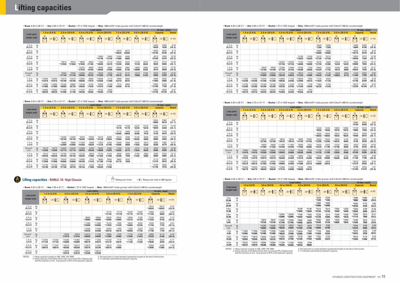
Lifting Capacities
Lifting capacities - R290LC-7A Rating over-side or 360 degreeRating over-front
Rating over-side or 360 degreeRating over-front
Boom: 6.25 m (20’ 6”) Arm: 2.50 m (8’ 2”) Bucket: 1.27 m3 SAE heaped Shoe : 600mm(24”) triple grouser with 5.2ton(11,460 lb) counterweight
Boom: 6.25 m (20’ 6”) Arm: 3.05 m (10’ 0”) Bucket: 1.27 m3 SAE heaped Shoe : 600mm(24”) triple grouser with 5.2ton(11,460 lb) counterweight
Boom: 6.25 m (20’ 6”) Arm: 3.75 m (12’ 4”) Bucket: 1.27 m3 SAE heaped Shoe : 600mm(24”) triple grouser with 5.2ton(11,460 lb) counterweight
Boom: 6.25 m (20’ 6”) Arm: 3.05 m (10’ 0”) Bucket: 1.27 m3 SAE heaped Shoe : 800mm(32”) triple grouser with 5.2ton(11,460 lb) counterweight
Boom: 6.25 m (20’ 6”) Arm: 2.10 m (6’ 11”) Bucket: 1.27 m3 SAE heaped Shoe : 600mm(24”) triple grouser with 5.2ton(11,460 lb) counterweight
Boom: 6.25 m (20’ 6”) Arm: 2.50 m (8’ 2”) Bucket: 1.27 m3 SAE heaped Shoe : 600mm(24”) triple grouser with 5.2ton(11,460 lb) counterweight
NOTES 1. Lifting capacity is based on SAE J1097, ISO 10567.2. Lifting capacity of the Robex Series does not exceed 75% of tipping load
with the machine on firm, level ground or 87% of full hydraulic capacity.
3. The load point is a hook (standard equipment) located on the back of the bucket.4. (*) indicates load limited by hydraulic capacity.
Lifting capacities - R290NLC-7A
7.5m25.0ft6.0m20.0ft4.5m15.0ft3.0m10.0ft1.5m5.0ft
GroundLine
-1.5m-5.0ft-3.0m-10.0ft-4.5m-15.0ft
kglbkglbkglbkglbkglbkglbkglbkglbkglb
*10390*22910*14060*31000*18380*40520
*10390*22910*14060*31000*18380*40520
*9590*21140*13470*29700*18180*40080
*17190*37900
*9590*21140*13470*29700*18180*40080
*17190*37900
*9910*21850
*9910*21850
*9820*21650*12250*27010*13580*29940*13920*30690*13440*29630
*11970*26390
*9820*216501018022440
970021380
950421030
960021160
985021720
*5960*13140
*7280*16050
*8590*18940
*9550*21050*10000*22050
*9830*21670
*8750*19290
*5960*13140
7050155406580
145106250
137806090
134306080
13400
626013800
*4910*10820
*5390*11880
*6090*13430
*6830*15060
*7420*16360
736016230
738016270
*4910*10820
516011380
489010780
464010230
444097904330955043509590
*4140*9130*4900
*10800*4310*9500
354078003410752033107300
*4460*9830*4600
*10140*4780
*105404610
101604580
101004770
105205260
11600*5980
*13180*5960
*13140
40008820331073002930646027406040270059502810619031206880378083305350
11790
8.94(29.3)
9.74(32.0)10.20(33.5)10.40(34.1)10.35(34.0)10.04(32.9)
9.44(31.0)
8.48(27.8)
6.97(22.9)
Load pointheight m(ft)
Load radius At max. reachCapacity9.0 m (30.0 ft)7.5 m (25.0 ft)6.0 m (20.0 ft)4.5 m (15.0 ft) Reach
m (ft)
1.5 m (5.0 ft) 3.0 m (10.0 ft)
NOTES 1. Lifting capacity is based on SAE J1097, ISO 10567.2. Lifting capacity of the Robex Series does not exceed 75% of tipping load
with the machine on firm, level ground or 87% of full hydraulic capacity.
3. The load point is a hook (standard equipment) located on the back of the bucket.4. (*) indicates load limited by hydraulic capacity.
Lifting capacities
Lifting capacities - R290LC-7A High Chassis Rating over-side or 360 degreeRating over-front
Boom: 6.25 m (20’ 6”) Arm: 3.05 m (10’ 0”) Bucket: 1.27 m3 SAE heaped Shoe : 600mm(24”) triple grouser with 5.2ton(11,460 lb) counterweight
Boom: 6.25 m (20’ 6”) Arm: 3.75 m (12’ 4”) Bucket: 1.27 m3 SAE heaped Shoe : 600mm(24”) triple grouser with 5.2ton(11,460 lb) counterweight
Boom: 6.25 m (20’ 6”) Arm: 2.50 m (8’ 2”) Bucket: 1.27 m3 SAE heaped Shoe : 600mm(24”) triple grouser with 5.2ton(11,460 lb) counterweight
NOTES 1. Lifting capacity is based on SAE J1097, ISO 10567.2. Lifting capacity of the Robex Series does not exceed 75% of tipping load
with the machine on firm, level ground or 87% of full hydraulic capacity.
3. The load point is a hook (standard equipment) located on the back of the bucket.4. (*) indicates load limited by hydraulic capacity.
Boom: 6.25 m (20’ 6”) Arm: 3.05 m (10’ 0”) Bucket: 1.27 m3 SAE heaped Shoe : 600mm(24”) triple grouser with 5.2ton(11,460 lb) counterweight
Boom: 6.25 m (20’ 6”) Arm: 3.75 m (12’ 4”) Bucket: 1.27 m3 SAE heaped Shoe : 600mm(24”) triple grouser with 5.2ton(11,460 lb) counterweight
Boom: 6.25 m (20’ 6”) Arm: 3.05 m (10’ 0”) Bucket: 1.27 m3 SAE heaped Shoe : 800mm(32”) triple grouser with 5.2ton(11,460 lb) counterweight
NOTES 1. Lifting capacity is based on SAE J1097, ISO 10567.2. Lifting capacity of the Robex Series does not exceed 75% of tipping load
with the machine on firm, level ground or 87% of full hydraulic capacity.
3. The load point is a hook (standard equipment) located on the back of the bucket.4. (*) indicates load limited by hydraulic capacity.
7.5m25.0ft6.0m20.0ft4.5m15.0ft3.0m10.0ft1.5m5.0ft
GroundLine
-1.5m-5.0ft-3.0m-10.0ft-4.5m-15.0ft
kglbkglbkglbkglbkglbkglbkglbkglbkglb
*11050*24360*14810*32650*19310*42570
*11050*24360*14810*32650*19310*42570
*6870*15150*10280*22660*14280*31480*19220*42370*16500*36380
*6870*15150*10280*22660*14280*31480*19220*42370*16500*36380
*10340*22800*12590*27760*13720*30250*13890*30620*13250*29210
*11530*25420
*10340*22800*12590*27760126202782012510275801260027780
*11530*25420
*6190*13650
*7540*16620
*8800*19400
*9670*21320*10020*22090
*9720*21430
*8350*18410
*6190*13650
*7540*16620
8380184708070
177907940
175007960
17550
819018060
*3320*7320*4980
*10980*5510
*12150*6230
*13730*6960
*15340*7510
*16560*7720
*17020*7350
*16200
*3320*7320*4980
*10980*5510
*121506210
136905950
131205760
127005680
125205720
12610
*2920*6440*4340*9570*4920
*10850
*2920*6440*4340*9570*4450*9810
*4480*9880*4640
*10230*4820
*10630*5040
*11110*5280
*11640*5540
*12210*5810
*12810*6010
*13250
*4480*9880
4170919037908360361079603610796037908360423093305170
11400
9.12(29.9)
9.85(32.3)10.26(33.7)10.41(34.2)10.31(33.8)
9.95(32.6)
9.29(30.5)
8.24(27.0)
Load pointheight m(ft)
Load radius At max. reachCapacity9.0 m (30.0 ft)7.5 m (25.0 ft)6.0 m (20.0 ft)4.5 m (15.0 ft) Reach
m (ft)
1.5 m (5.0 ft) 3.0 m (10.0 ft)
HYUNDAI CONSTRUCTION EQUIPMENT 18 / 19


![Arasan.Corporate Overview 09.09]](https://static.fdocuments.in/doc/165x107/54c3ac9b4a7959ca568b45f8/arasancorporate-overview-0909.jpg)