![Catalogue > complete catalogue [(] radicalmatters.com ...](https://static.fdocuments.in/doc/165x107/616fb57120885b2db26f2304/catalogue-gt-complete-catalogue-.jpg)
QVF Supraline Catalogue
227
1. VF ® SUPRA LINE 2. VF ® COMPONENTS 3. VF ® ENGINEERED SYSTEMS 4. VF ® PROCESS SYSTEMS PROCESS SOLUTIONS IN GLASS THE WORLD OF Copyright © De Dietrich Process Systems GmbH Hattenbergstraße 36, D-55122 Mainz 8003.e.0
-
Upload
chemlab-international -
Category
Documents
-
view
538 -
download
25
description
New QVF Components Catalogue 2012
Transcript of QVF Supraline Catalogue

1. VF® SUPRA LINE
2. VF® COMPONENTS
3. VF® ENGINEERED SYSTEMS
4. VF® PROCESS SYSTEMS
PROCESS SOLUTIONS IN GLASSTHE WORLD OF
Copyright © De Dietrich Process Systems GmbH Hattenbergstraße 36, D-55122 Mainz
8003.e.0

P400d08003.1
������������� �������
2. Pipeline Components
3. Valves and Filters
4. Vessels
5. Heat Exchangers
6. Column Components
������������
8. Measurement and Control
9. Couplings
10. Structures and Supports
The Component System

P401e.08003.1
1. TECHNICAL INFORMATION
2. Pipeline Components
3. Valves and Filters
4. Vessels
5. Heat Exchangers
6. Column Components
������������
8. Measurement and Control
9. Couplings
10. Structures and Supports
The Component System

1 Technical Information / Technische Information
1.2-Rev. 0 QVF® SUPRA-LineP401de.0
8003.1
Contents / Inhaltsverzeichnis
Reference Ar� kel-Bezeichnung Page / Seite
Process plant in borosilicate glass 3.3 Apparatebau in Borosilicatglas 3.3 3
Chemical composi� on of borosilicate glass 3.3 Chemische Zusammensetzung von Borosilicatglas 3.3 3
Proper� es of borosilicate glass 3.3 Eigenscha� en von Borosilicatglas 3.3 3
Chemical resistance Chemische Beständigkeit 4
Physical proper� es Physikalische Eigenscha� en 4
Acid corrosion resistance of borosilicate glass 3.3 Säurebeständigkeit von Borosilicatglas 3.3 5
Caus� c corrosion resistance of borosilicate glass 3.3 Laugenbeständigkeit von Borosilicatglas 3.3 6
Op� cal proper� es Op� sche Eigenscha� en 7
Mechanical proper� es Mechanische Eigenscha� en 7
Permissible opera� ng condi� ons Zulässige Betriebstemperatur 8
Thermal shock Temperaturschock 8
General opera� ng data Allgemeine Betriebsdaten 8
Permissible opera� ng pressure Zulässiger Betriebsdruck 9
Reduced opera� ng condi� ons Reduzierte Betriebsbedingungen 9
Design of glass components Dimensionierung von Glasbauteilen 10
Marking of glass components Kennzeichnung der Glasbauteile 11
Glass ends Rohrenden 12
Alignment of glass pipes Auswinkelbarkeit von Rohren 13
GMP-compliant installa� ons GMP-gerechte Installa� onen 14
Protec� on against mechanical damage Schutz gegen mechanische Einwirkungen von außen 14
Coated glass components Beschichtete Glasbauteile 14
Glass plants in explosive atmosphere Glasanlagen im Ex-Bereich 15
Risk analysis / residual risks Gefahrenanalyse / Restgefahren 15-16
Technical data are subject to change. All rights reserved. Copyright © De Dietrich Process Systems GmbH.
Technische Änderungen und Irrtümer vor-behalten. Copyright © De Dietrich Process Systems GmbH .

1 Technical Information / Technische Information
1.3-Rev. 0QVF® SUPRA-LineP401de.08003.1
Apparatebau in Borosilicat-Apparatebau in Borosilicat-glas 3.3glas 3.3QVF®-Rohrleitungen, -Apparate und -Anlagen aus Borosilicatglas 3.3 sind in der chemischen und pharmazeu� schen Industrie weit verbreitet. Die besonderen Eigenscha� en, insbesondere die hohe chemische Resistenz, die Temperaturbeständigkeit und der geringe Längenausdehnungskoe� zient des von uns für den Glasapparatebau ausschließlich verwendeten Werksto� es Borosilicatglas 3.3 tragen hierzu ebenso bei wie die Tatsache, dass es sich bei Borosilicatglas 3.3 um ein für den Bau von Druckbehältern zugelassenes und erprobtes Material handelt.
Process plant in borosilicate Process plant in borosilicate glass 3.3 glass 3.3 QVF® process plant and pipeline components manufactured from borosilicate glass 3.3 are widely used throughout the chemical and pharmaceu� cal industries. The special proper� es – especially its high chemical resistance, its resistance to temperature and its low coe� cient of linear thermal expansion – of the borosilicate glass 3.3 exclusively used by QVF® for the construc� on of glass plants and pipelines is one reason for this widespread use. Secondly, borosilicate glass is an approved and proven material in the construc� on of pressure equipment.
Component / Bezeichnung % by weight / Anteil in Gew.-%
SiOSiO22 80,680,6
BB22OO33 12,512,5
NaNa22OO 4,24,2
AlAl22OO33 2,22,2
Table 1.1 / Table 1.1 / Tabelle 1.1Tabelle 1.1
Properties of borosilicate Properties of borosilicate glass 3.3glass 3.3The very wide use of this material throughout the world is mainly due to its chemical and thermal proper� es (see also EN 1595) together with a great number of other bene� ts that dis� nguish borosilicate glass 3.3 from other materials of construc� on. These include special proper� es such as:• smooth, non-porous surface• no cataly� c e� ect• no adverse physiological proper� es• neutral smell and taste• non-� ammability• transparency• sustainability
Eigenschaften von Borosilicat-Eigenschaften von Borosilicat-glas 3.3glas 3.3Der weltweit sehr vielfäl� ge Einsatz dieses Werksto� es basiert insbesondere auf dessen chemischen und thermischen Eigenscha� en sowie auf einer Vielzahl weiterer Vorteile, die Borosilicatglas 3.3 gegenüber anderen Konstruk� onsmaterialien auszeichnet (siehe EN1595). Hierzu zählen besondere Eigenscha� en wie:
• gla� e, porenfreie Ober� äche• kataly� sche Indi� erenz• physiologische Unbedenklichkeit• Geruchs- und Geschmacksneutralität• Unbrennbarkeit• Durchsich� gkeit• Recyclefähigkeit
Chemische Zusammensetzung von Chemische Zusammensetzung von Borosilicatglas 3.3Borosilicatglas 3.3
Chemical composition of borosili-Chemical composition of borosili-cate glass 3.3cate glass 3.3

1 Technical Information / Technische Information
1.4-Rev. 0 QVF® SUPRA-LineP401de.0
8003.1
Chemical resistanceChemical resistanceBorosilicate glass 3.3 is resistant to chemical a� ack by almost all products, which makes its resistance much more comprehensive than that of other well-known materials. It is highly resistant to water, saline solu� ons, organic substances, halogens such as chlorine and bromine and also many acids. There are only a few chemicals which can cause no� ceable corrosion of the glass surface namely hydro� uoric acid, concentrated phosphoric acid and strong caus� c solu� ons at elevated temperatures. However, at ambient temperatures caus� c solu� ons up to 30 % concentra� on can be handled by borosilicate glass 3.3 without di� culty.Borosilicate glass 3.3 can be classi� ed in accordance with the relevant test methods as follows (see also ISO 3585 and EN 1595):
Chemische BeständigkeitChemische BeständigkeitBorosilicatglas 3.3 weist eine gegen fast alle Produkte und damit im Vergleich zu anderen bekannten Werksto� en umfassendere chemische Beständigkeit auf. So ist es sehr gut resistent gegen Wasser, Salzlösungen, organische Substanzen, Halogene wie z.B. Chlor und Brom und auch gegen viele Säuren. Zu einem merklichen Abtrag der Glasober-� äche führen dagegen z.B. Flusssäure sowie konzentrierte Phosphorsäure und starke Laugen bei höheren Temperaturen. Borosilicatglas 3.3 kann jedoch bei Raum-temperatur ohne Schwierigkeiten in Verbin-dung mit Laugen bis zu einer Konzentra� on von 30 % eingesetzt werden.
Eine Klassi� zierung des Werksto� es Borosili-catglas 3.3 nach den einschlägigen Unter-suchungsmethoden führt zu folgendem Ergebnis (s. auch ISO 3585 und EN 1595):
Table 1.2 / Table 1.2 / Tabelle 1.2Tabelle 1.2
Hydrolytic resistance at 98°CHydrolytic resistance at 98°CWasserbeständigkeit bei 98°CWasserbeständigkeit bei 98°C
Hydrolytic resistance grain class ISO 719-HGB 1Hydrolytic resistance grain class ISO 719-HGB 1Grieß-Wasserbeständigkeit Klasse ISO 719-HGB 1Grieß-Wasserbeständigkeit Klasse ISO 719-HGB 1
Hydroly� c resistance at 121°CWasserbeständigkeit bei 121°C
Hydroly� c resistance grain class ISO 720-HGA 1Grieß-Wasserbeständigkeit Klasse ISO 720-HGA 1
Acid resistanceSäurebeständigkeit
Deposit of Na2O < 100 mg/dm2 to ISO 1776Abgabe Na2O < 100 mg/dm2 nach ISO 1776
Alkali resistanceLaugenbeständigkeit
Alkali resistance class ISO 695-A2Laugenbeständigkeitsklasse ISO 695-A2
Physical propertiesPhysical propertiesThe most important physical properties for The most important physical properties for the construction of plant are listed below the construction of plant are listed below (see also ISO 3585 and EN 1595).(see also ISO 3585 and EN 1595).
Physikalische EigenschaftenPhysikalische EigenschaftenDie für den Apparatebau wich� gsten physi-kalischen Eigenscha� en sind nachstehend aufgeführt (s. auch DIN ISO 3585 und EN 1595).
Table 1.3 / Table 1.3 / Tabelle 1.3Tabelle 1.3
Mean linear thermal expansion coefficientMean linear thermal expansion coefficientMittlerer linearer WärmeausdehnungskoeffizientMittlerer linearer Wärmeausdehnungskoeffizient
�� 20/300 20/300 = (3,3 ± 0,1) x 10= (3,3 ± 0,1) x 10�6�6 K K-1 -1
Mean thermal conductivity between 20 and 200 °CMean thermal conductivity between 20 and 200 °CMittlere Wärmeleitfähigkeit zwischen 20 und 200°C Mittlere Wärmeleitfähigkeit zwischen 20 und 200°C
� 20/200 = 1,2 W/m�K
Mean specific heat capacity between 20 and 100 °CMean specific heat capacity between 20 and 100 °CMittlere spezifische Wärmekapazität zwischen 20 und 100 °CMittlere spezifische Wärmekapazität zwischen 20 und 100 °C
Cp20/100 = 0,8 kJ/kg�K
Mean specific heat capacity between 20 and 200 °CMean specific heat capacity between 20 and 200 °CMittlere spezifische Wärmekapazität zwischen 20 und 200 °CMittlere spezifische Wärmekapazität zwischen 20 und 200 °C
Cp20/200 = 0,9 kJ/kg�K
Density at 20 °CDensity at 20 °CDichte bei 20 °CDichte bei 20 °C
�� = 2,23 kg/dm = 2,23 kg/dm33

1 Technical Information / Technische Information
1.5-Rev. 0QVF® SUPRA-LineP401de.08003.1
Further informa� on about acid and alkali a� ack can be obtained from the following � gures.The corrosion curves in � g. 1.1 show a maximum for di� erent acids in the concentra� on range between 4 and 7 n (HCl for example at the azeotrope with 20.2 weight %). Above that the reac� on speed decreases markedly so that the eroded layer amounts to only a few thousandths of millimetre a� er some years. There is, therefore, jus� � ca� on for referring to borosilicate glass 3.3 as an acid-resistant material.
Weitere Informa� onen über den Säure- und Laugenangriff lassen sich den nach-folgenden Abbildungen entnehmen.
Die Abtragskurven in Abb. 1.1 zeigen für verschiedene Säuren ein Maximum in dem Konzentra� onsbereich zwischen 4 und 7 n (HCl z.B. beim Azeotrop mit 20,2 Gew.-%). Darüber nimmt die Reak� onsgeschwindig-keit merklich ab, so dass die abgetragene Schicht nach Jahren lediglich einige tau-sendstel Millimeter beträgt. Man spricht also bei Borosilicatglas 3.3 zu Recht von einem säurebeständigen Material.
Fig. 1.1 Fig. 1.1 Acid attack on borosilicate glass 3.3 as a func-Acid attack on borosilicate glass 3.3 as a func-tion of concentration tion of concentration
Abb. 1.1Abb. 1.1Säureangriff an Borosilicatglas 3.3 in Abhängig-Säureangriff an Borosilicatglas 3.3 in Abhängig-keit von der Konzentrationkeit von der Konzentration
Säurebeständigkeit von Borosili-Säurebeständigkeit von Borosili-catglas 3.3catglas 3.3
Acid corrosion resistance of Acid corrosion resistance of borosilicate glass 3.3 borosilicate glass 3.3

1 Technical Information / Technische Information
1.6-Rev. 0 QVF® SUPRA-LineP401de.0
8003.1
Fig. 1.2 Alkali a� ack on borosilicate glass 3.3 as a func� on of temperature
Abb. 1.2Laugenangri� an Borosilicatglas 3.3 in Abhängig-keit von der Temperatur
It can be seen from the corrosion curves in � g. 1.2 that the a� ack on the glass surface ini� ally increases as the concentra� on of the caus� c solu� on increases but a� er exceeding a maximum it assumes a virtually constant value. Rising temperatures increase the corrosion, while at low temperatures the reac� on speed is so low that reduc� on of the wall thickness is hardly detectable over a number of years.
Die Abtragskurven in Abb. 1.2 lassen erkennen, dass der Angri� auf die Glasober� äche mit zunehmender Konzentra� on der Laugen zunächst ansteigt und nach Überschreiten eines Maximums einen nahezu konstanten Wert annimmt. Steigende Temperaturen erhöhen den Abtrag, während bei niedrigen Temperaturen die Reak� onsgeschwindigkeit so gering ist, dass über Jahre hinweg kaum eine Wanddickenabnahme feststellbar ist.
Laugenbeständigkeit von Boro-Laugenbeständigkeit von Boro-silicatglas 3.3silicatglas 3.3
Caustic corrosion resistance of Caustic corrosion resistance of borosilicate glass 3.3 borosilicate glass 3.3

1 Technical Information / Technische Information
1.7-Rev. 0QVF® SUPRA-LineP401de.08003.1
Optical propertiesOptical propertiesBorosilicate glass 3.3 shows no appreciable light absorp� on in the visible area of the spectrum, and consequently it is clear and colourless.If photosensi� ve substances are being processed, it is recommended that brown coated borosilicate glass 3.3 is used. This special coa� ng reduces the UV light transmission to a minimum, since the absorp� on limit, as can also be seen from the � gure below, is shi� ed to approximately 500 nm.Sectrans coated glass components, which have an absorp� on limit of approximately 380 nm, are also ideal for these applica� ons.
Optische EigenschaftenOptische EigenschaftenBorosilicatglas 3.3 zeigt im sichtbaren Spektralbereich keine wesentliche Absorp� on und wirkt somit klar und farblos.
Sollen lichtemp� ndliche Substanzen verarbeitet werden, so emp� ehlt sich die Verwendung von braun beschichtetem Borosilicatglas 3.3 (Braunglas). Durch diese Spezialbeschichtung wird die UV-Licht-durchlässigkeit auf ein Minimum reduziert, da sich die Absorp� onskante, wie ebenfalls aus nachstehender Abbildung ersichtlich ist, auf ca. 500 nm verschiebt.
Mit Sectrans beschichtete Glasbauteile, deren Absorp� onskante bei ca. 380 nm liegt, eignen sich ebenfalls für diese Anwendungen.
Fig. 1.3 Transmission curves for borosilicate glass 3.3
Abb. 1.3Transmissionskurven für Borosilicatglas 3.3
Mechanical propertiesMechanical propertiesThe permissible tensile strength of borosilicate glass 3.3 includes a safety factor which takes into account prac� cal experience on the behaviour of glass. The design � gures indicated in the table below and speci� ed in EN 1595 therefore apply to the permissible tensile, bending and compressive stress to which glass components may be subjected taking into account the surface condi� on of the glass in service.
Mechanische EigenschaftenMechanische EigenschaftenDie zulässigen Fes� gkeitskennwerte von Borosilicatglas 3.3 beinhalten einen Sicher-heitsfaktor, der den Erfahrungen über das Fes� gkeitsverhalten von Glas Rechnung trägt.
So gelten die in nachstehender Tabelle auf-geführten und in der EN 1595 festgelegten Berechnungskennwerte für die zulässige Beanspruchung von Glasbauteilen durch Zug-, Biege- und Druckspannungen bei der in der Praxis zu erwartenden Ober� ächen-bescha� enheit.
Tensile and bending strengthZug- und Biegefes� gkeit
K/S = 7 N/mmK/S = 7 N/mm22
Compressive strengthDruckfes� gkeit
K/S = 100 N/mmK/S = 100 N/mm22
Modulus of elas� city Elas� zitätsmodul
E = 64 kN/mmE = 64 kN/mm22
Poisson‘s ratio (transverse contraction figure) Poisson-Zahl (Querkontrak� onszahl)
� = 0,2� = 0,2
Table 1.4 / Table 1.4 / Tabelle 1.4Tabelle 1.4
1 Technical Information / Technische Information
1.8-Rev. 0 QVF® SUPRA-LineP401de.0
8003.1
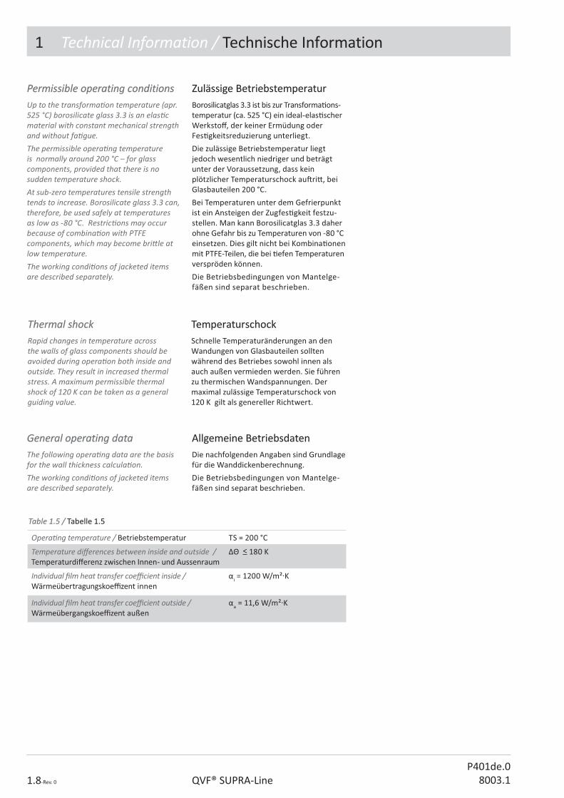
Thermal shockThermal shockRapid changes in temperature across the walls of glass components should be avoided during opera� on both inside and outside. They result in increased thermal stress. A maximum permissible thermal shock of 120 K can be taken as a general guiding value.
TemperaturschockTemperaturschockSchnelle Temperaturänderungen an den Wandungen von Glasbauteilen sollten während des Betriebes sowohl innen als auch außen vermieden werden. Sie führen zu thermischen Wandspannungen. Der maximal zulässige Temperaturschock von 120 K gilt als genereller Richtwert.
Opera� ng temperature / Betriebstemperatur TS = 200 °C
Temperature di� erences between inside and outside / Temperaturdi� erenz zwischen Innen- und Aussenraum
�� < 180 K
Individual � lm heat transfer coe� cient inside / Wärmeübertragungskoe� zent innen
�i = 1200 W/m²�K
Individual � lm heat transfer coe� cient outside / Wärmeübergangskoe� zent außen
�a = 11,6 W/m²�K
Allgemeine BetriebsdatenAllgemeine BetriebsdatenDie nachfolgenden Angaben sind Grundlage für die Wanddickenberechnung.
Die Betriebsbedingungen von Mantelge-fäßen sind separat beschrieben.
General operating dataGeneral operating dataThe following opera� ng data are the basis for the wall thickness calcula� on.The working condi� ons of jacketed items are described separately.
Permissible operating conditionsPermissible operating conditionsUp to the transforma� on temperature (apr. 525 °C) borosilicate glass 3.3 is an elas� c material with constant mechanical strength and without fa� gue.The permissible opera� ng temperature is normally around 200 °C – for glass components, provided that there is no sudden temperature shock. At sub-zero temperatures tensile strength tends to increase. Borosilicate glass 3.3 can, therefore, be used safely at temperatures as low as -80 °C. Restric� ons may occur because of combina� on with PTFE components, which may become bri� le at low temperature.The working condi� ons of jacketed items are described separately.
Zulässige BetriebstemperaturZulässige BetriebstemperaturBorosilicatglas 3.3 ist bis zur Transforma� ons-temperatur (ca. 525 °C) ein ideal-elas� scher Werksto� , der keiner Ermüdung oder Fes� gkeitsreduzierung unterliegt.
Die zulässige Betriebstemperatur liegt jedoch wesentlich niedriger und beträgt unter der Voraussetzung, dass kein plötzlicher Temperaturschock au� ri� , bei Glasbauteilen 200 °C.
Bei Temperaturen unter dem Gefrierpunkt ist ein Ansteigen der Zugfes� gkeit festzu-stellen. Man kann Borosilicatglas 3.3 daher ohne Gefahr bis zu Temperaturen von -80 °C einsetzen. Dies gilt nicht bei Kombina� onen mit PTFE-Teilen, die bei � efen Temperaturen verspröden können.
Die Betriebsbedingungen von Mantelge-fäßen sind separat beschrieben.
Table 1.5 / Table 1.5 / Tabelle 1.Tabelle 1.55

1 Technical Information / Technische Information
1.9-Rev. 0QVF® SUPRA-LineP401de.08003.1
Permissible operating pressurePermissible operating pressureGlass components in all nominal sizes can be used with full vacuum (-1 bar g) on the product side, provided they are not specially marked otherwise.The permissible working pressure is given in accordance to the general opera� ng condi� on and the main diameter of the glass component or the volume of a spherical vessel. In some cases the reduced working pressure is men� oned in the descrip� on of the item.The internal heat exchange areas of heat exchangers are handled separately in Sec� on 5 under the par� cular product descrip� on. In cases where glass equipment is operated with a gas pressure, appropriate safety precau� ons are required.
Zulässiger BetriebsdruckZulässiger BetriebsdruckGlasbauteile aller Nennweiten können bei vollem Vakuum (-1 bar) im Produktraum eingesetzt werden, sofern sie nicht besonders gekennzeichnet sind.
Der zulässige Betriebsüberdruck von Glas-bauteilen ist abhängig von den angegebenen allgemeinen Betriebsbedingungen und der Hauptnennweite oder dem Volumen der Kugeln. Reduzierte Drücke sind bei den entsprechenden Bauteilen angegeben.
Die Innenräume von Wärmeübertragern werden im Kapitel 5 bei den jeweiligen Produktbeschreibungen gesondert behandelt.
Bei einem Gasüberdruck in Glasapparaturen sind geeignete Schutzvorrichtungen erforder-lich.
V(l) / D(mm)V(l) / D(mm) 5/2255/225 10/28010/280 20/35020/350 50/49050/490 100/610100/610 200/750200/750 500/1005500/1005
PS (bar g) 2 1 1 1 0,8 0,6 0,3
KugelgefäßeSpherical vessels
Reduzierte BetriebsbedingungenReduzierte BetriebsbedingungenHaben Bauteile reduzierte Betriebsbedin-gungen sind diese in der Beschreibung des Ar� kels angegeben.
Reduced operating conditionsReduced operating conditionsAr� cles may have reduced working condi� ons which are men� oned in the descrip� on of the ar� cle.
Zylindrische GlasbauteileCylindrical Glass itemsCylindrical Glass itemsDNDN 1515 2525 4040 5050 8080 100100 150150 200200 300300 450450 600600 800800 10001000
PS (bar g) 4 4 4 4 3 2 2 1 1 1 1 1 1
Table 1.6 / Table 1.6 / Tabelle 1.Tabelle 1.66
Table 1.7 / Table 1.7 / Tabelle 1.Tabelle 1.77
1 Technical Information / Technische Information
1.10-Rev. 0 QVF® SUPRA-LineP401de.0
8003.1
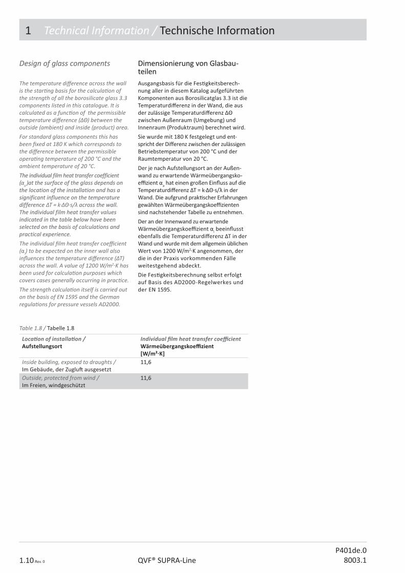
Design of glass componentsDesign of glass components
The temperature di� erence across the wall is the star� ng basis for the calcula� on of the strength of all the borosilicate glass 3.3 components listed in this catalogue. It is calculated as a func� on of the permissible temperature di� erence () between the outside (ambient) and inside (product) area.For standard glass components this has been � xed at 180 K which corresponds to the di� erence between the permissible opera� ng temperature of 200 °C and the ambient temperature of 20 °C. The individual film heat transfer coefficient The individual film heat transfer coefficient ((�a ))at the surface of the glass depends on at the surface of the glass depends on the location of the installation and has a the location of the installation and has a significant influence on the temperature significant influence on the temperature difference difference T = k··s/� across the wall. across the wall. The individual film heat transfer values The individual film heat transfer values indicated in the table below have been indicated in the table below have been selected on the basis of calculations and selected on the basis of calculations and practical experience. practical experience. The individual � lm heat transfer coe� cient (�i) to be expected on the inner wall also in� uences the temperature di� erence (T) across the wall. A value of 1200 W/m2 K has been used for calcula� on purposes which covers cases generally occurring in prac� ce.The strength calcula� on itself is carried out on the basis of EN 1595 and the German regula� ons for pressure vessels AD2000.
Dimensionierung von Glasbau-Dimensionierung von Glasbau-teilenteilenAusgangsbasis für die Fes� gkeitsberech-nung aller in diesem Katalog aufgeführten Komponenten aus Borosilicatglas 3.3 ist die Temperaturdi� erenz in der Wand, die aus der zulässige Temperaturdi� erenz �� zwischen Außenraum (Umgebung) und Innenraum (Produktraum) berechnet wird.
Sie wurde mit 180 K festgelegt und ent-spricht der Di� erenz zwischen der zulässigen Betriebstemperatur von 200 °C und der Raumtemperatur von 20 °C.
Der je nach Aufstellungsort an der Außen-wand zu erwartende Wärmeübergangsko-e� zient �a hat einen großen Ein� uss auf die Temperaturdi� erenz �T = k·��·s/! in der Wand. Die aufgrund prak� scher Erfahrungen gewählten Wärmeübergangskoe� zienten sind nachstehender Tabelle zu entnehmen.
Der an der Innenwand zu erwartende Wärmeübergangskoe� zient �i beein� usst ebenfalls die Temperaturdi� erenz �T in der Wand und wurde mit dem allgemein üblichen Wert von 1200 W/m2�K angenommen, der die in der Praxis vorkommenden Fälle weitestgehend abdeckt.
Die Fes� gkeitsberechnung selbst erfolgt auf Basis des AD2000-Regelwerkes und der EN 1595.
Table 1.8 / Tabelle 1.8
Loca� on of installa� on /Aufstellungsort
Individual � lm heat transfer coe� cient Wärmeübergangskoe� zient [W/m²�K]
Inside building, exposed to draughts /Im Gebäude, der Zuglu� ausgesetzt
11,611,6
Outside, protected from wind / Im Freien, windgeschützt
11,611,6

1 Technical Information / Technische Information
1.11-Rev. 0QVF® SUPRA-LineP401de.08003.1
Marking of glass componentsMarking of glass componentsThe basis for the marking of borosilicate glass 3.3 components is the Pressure Equipment Direc� ve 97/23/EC and European Standard EN 1595 („Pressure equipment made from borosilicate glass 3.3”).Addi� onal informa� on on the component is provided for quality assurance purposes (traceability, correct use by the customer, etc) and has been approved by the No� � ed Body responsible for monitoring our compliance with the direc� ve.The di� erent marking possibili� es listed in � g. 1.4 to 1.6 are used as follows:
Kennzeichnung der GlasbauteileKennzeichnung der GlasbauteileGrundlage für die Kennzeichnung der Bauteile aus Borosilicatglas 3.3, die für Druckbehälter Verwendung � nden können, sind die Druckgeräte-Richtlinie 97/23/EG sowie die Norm EN 1595 („Druckgeräte aus Borosilicatglas 3.3“).
Darüber hinaus gehende Angaben auf dem Bauteil dienen der Qualitätssicherung (Rückverfolgbarkeit, rich� ger Einsatz beim Kunden, etc.) und wurden mit der benannten Stelle abges� mmt, die für die Überwachung unseres QM-Systems und unserer Fer� gung zuständig ist.
Die in den Abb. 1.4 bis 1.6 dargestellten unterschiedlichen Kennzeichnungsmöglich-keiten � nden wie folgt Anwendung:
Table 1.9 / Tabelle 1.9
Table 1.10 / Tabelle 1.10
Fig. / Abb. 1.4 Standard parts acc. to catalogue / Katalogteile
Fig. / Abb. 1.5 Special parts subject to catalogue opera� ng condi� ons / Sonderteile mit Katalog-Betriebsbedingungen
Fig. / Abb. 1.6 Special parts of which permissible opera� ng pressure and/or temperatures di� er from the details in this catalogue / Sonderteile, deren zulässige Betriebsüberdrücke und/oder Temperaturen von den Katalogbedingungen abweichen
Contrary to table 1.9 components for DN 15 and DN 25 have to be supplied without CE mark (see ar� cle 3, paragraph 3 of direc� ve 97/23/EC on this point).The following information can be obtained The following information can be obtained in detail from the marking:in detail from the marking:
Abweichend von Tabelle 1.9 dürfen Bau-teile mit den Hauptnennweiten DN 15 und DN 25 kein CE-Zeichen erhalten (s. hierzu Ar� kel 3, Absatz 3 der Richtlinie 97/23/EG).
Aus der Kennzeichnung können Sie im Ein-zelnen folgende Informa� onen entnehmen:
Part of mark /Part of mark /KennzeichnungKennzeichnung
Meaning / Meaning / BedeutungBedeutung
QVF®-logo-logo Manufacturer / Manufacturer / HerstellerHersteller
CE 0035CE 0035 Notified Body’s identification number /Notified Body’s identification number /Kennnummer der benannten StelleKennnummer der benannten Stelle
Boro 3.3Boro 3.3 Material borosilicate glass 3.3 / Material borosilicate glass 3.3 / Werkstoff Borosilicatglas 3.3Werkstoff Borosilicatglas 3.3
MM Place of manufacture / Place of manufacture / Herstellungsort M=Mainz (D)Herstellungsort M=Mainz (D)
77 Strength parameter / Strength parameter / Festigkeitskennwert nach EN 1595Festigkeitskennwert nach EN 1595
0303 Catalogue issue 8003/ Catalogue issue 8003/ Katalogreferenz 8003Katalogreferenz 8003
123456123456 Batch serial number / Batch serial number / FertigungsnummerFertigungsnummer
2PL15100...2PL15100... Catalogue reference / Catalogue reference / StandardartikelnummerStandardartikelnummer
SL 4713SL 4713 Drawing number or special item with permissible operating pressure as Drawing number or special item with permissible operating pressure as in the catalogue / in the catalogue / Sonderteil mit Katalog-BetriebsbedingungenSonderteil mit Katalog-Betriebsbedingungen
PS = -1/+5 barPS = -1/+5 bar Permissible operating pressure, deviating from the catalogue / Permissible operating pressure, deviating from the catalogue / vom Katalog abweichender zulässiger Betriebsüberdruckvom Katalog abweichender zulässiger Betriebsüberdruck
TS = 200 °CTS = 200 °C Permissible operating temperature, deviating from the catalogue / Permissible operating temperature, deviating from the catalogue / vom Katalog abweichender maximal zulässige Betriebstemperaturvom Katalog abweichender maximal zulässige Betriebstemperatur
�� " �� " 180 K180 K Permissible temperature difference / Permissible temperature difference / Zulässige TemperaturdifferenzZulässige Temperaturdifferenz
Fig. /Fig. / Abb. 1.4 Abb. 1.4
Fig. /Fig. / Abb. 1.6 Abb. 1.6
Fig. /Fig. / Abb. 1.5 Abb. 1.5
1 Technical Information / Technische Information
1.12-Rev. 0 QVF® SUPRA-LineP401de.0
8003.1
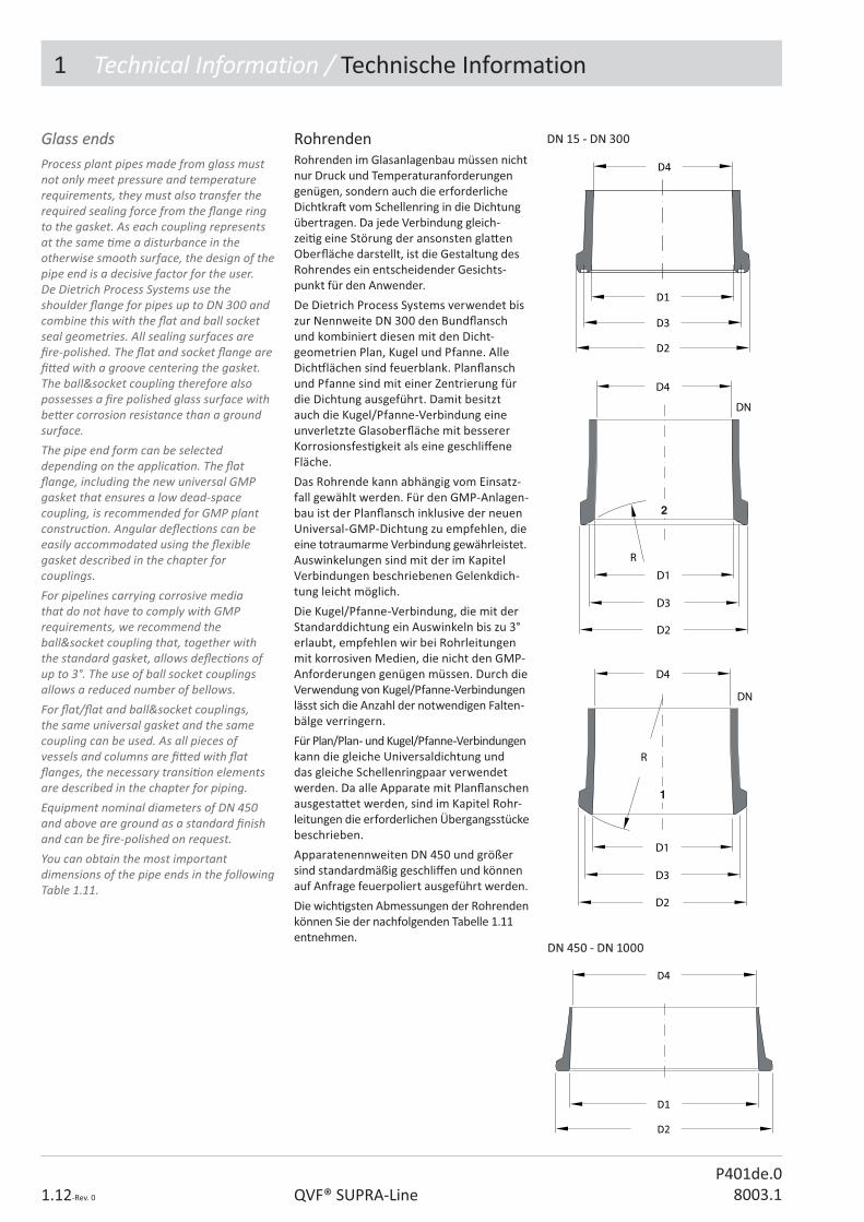
Glass endsGlass endsProcess plant pipes made from glass must not only meet pressure and temperature requirements, they must also transfer the required sealing force from the � ange ring to the gasket. As each coupling represents at the same � me a disturbance in the otherwise smooth surface, the design of the pipe end is a decisive factor for the user.De Dietrich Process Systems use the shoulder � ange for pipes up to DN 300 and combine this with the � at and ball socket seal geometries. All sealing surfaces are � re-polished. The � at and socket � ange are � � ed with a groove centering the gasket. The ball&socket coupling therefore also possesses a � re polished glass surface with be� er corrosion resistance than a ground surface.The pipe end form can be selected depending on the applica� on. The � at � ange, including the new universal GMP gasket that ensures a low dead-space coupling, is recommended for GMP plant construc� on. Angular de� ec� ons can be easily accommodated using the � exible gasket described in the chapter for couplings. For pipelines carrying corrosive media that do not have to comply with GMP requirements, we recommend the ball&socket coupling that, together with the standard gasket, allows de� ec� ons of up to 3°. The use of ball socket couplings allows a reduced number of bellows.For � at/� at and ball&socket couplings, the same universal gasket and the same coupling can be used. As all pieces of vessels and columns are � � ed with � at � anges, the necessary transi� on elements are described in the chapter for piping. Equipment nominal diameters of DN 450 and above are ground as a standard � nish and can be � re-polished on request.You can obtain the most important dimensions of the pipe ends in the following Table 1.11.
RohrendenRohrenden im Glasanlagenbau müssen nicht nur Druck und Temperaturanforderungen genügen, sondern auch die erforderliche Dichtkra� vom Schellenring in die Dichtung übertragen. Da jede Verbindung gleich-zei� g eine Störung der ansonsten gla� en Ober� äche darstellt, ist die Gestaltung des Rohrendes ein entscheidender Gesichts-punkt für den Anwender.
De Dietrich Process Systems verwendet bis zur Nennweite DN 300 den Bund� ansch und kombiniert diesen mit den Dicht-geometrien Plan, Kugel und Pfanne. Alle Dich# lächen sind feuerblank. Plan� ansch und Pfanne sind mit einer Zentrierung für die Dichtung ausgeführt. Damit besitzt auch die Kugel/Pfanne-Verbindung eine unverletzte Glasober� äche mit besserer Korrosionsfes� gkeit als eine geschli� ene Fläche.
Das Rohrende kann abhängig vom Einsatz-fall gewählt werden. Für den GMP-Anlagen-bau ist der Plan� ansch inklusive der neuen Universal-GMP-Dichtung zu empfehlen, die eine totraumarme Verbindung gewährleistet. Auswinkelungen sind mit der im Kapitel Verbindungen beschriebenen Gelenkdich-tung leicht möglich.
Die Kugel/Pfanne-Verbindung, die mit der Standarddichtung ein Auswinkeln bis zu 3° erlaubt, empfehlen wir bei Rohrleitungen mit korrosiven Medien, die nicht den GMP-Anforderungen genügen müssen. Durch die Verwendung von Kugel/Pfanne-Verbindungen lässt sich die Anzahl der notwendigen Falten-bälge verringern.
Für Plan/Plan- und Kugel/Pfanne-Verbindungen kann die gleiche Universaldichtung und das gleiche Schellenringpaar verwendet werden. Da alle Apparate mit Plan� anschen ausgesta� et werden, sind im Kapitel Rohr-leitungen die erforderlichen Übergangsstücke beschrieben.
Apparatenennweiten DN 450 und größer sind standardmäßig geschli� en und können auf Anfrage feuerpoliert ausgeführt werden.
Die wich� gsten Abmessungen der Rohrenden können Sie der nachfolgenden Tabelle 1.11 entnehmen.
DN 15 - DN 300 DN 15 - DN 300
DN 450 - DN 1000DN 450 - DN 1000

1 Technical Information / Technische Information
1.13-Rev. 0QVF® SUPRA-LineP401de.08003.1
Table 1.11 / Tabelle 1.11
DN D1 D2 D3 D41515 1515 3030 2323 14,1 – 15,914,1 – 15,9
2525 2424 4444 3434 22,75 – 25,2522,75 – 25,25
4040 3737 6262 4848 35,2 – 38,835,2 – 38,8
5050 5050 7676 60,560,5 48 – 5248 – 52
8080 7676 109109 8888 74,5 – 79,574,5 – 79,5
100100 101101 130130 120,5120,5 97,7 – 104,397,7 – 104,3
150150 153153 184184 172172 147 – 155147 – 155
200200 203203 233233 220220 196 – 205196 – 205
300300 300300 338338 321321 294 – 307294 – 307
450450 457457 528528 -- 444 – 456444 – 456
600600 614614 686,5686,5 -- 592 – 599592 – 599
800800 838 – 816838 – 816 920920 -- 799 – 805799 – 805
10001000 1052 – 9881052 – 988 10931093 -- 976 – 983 976 – 983
Alignment of glass pipesAlignment of glass pipesBefore the sealing force is applied, glass parts can be aligned at an angle to each other so that horizontal pipelines can be laid with a gradient � without the need for addi� onal components. The following table shows the maximum permi� ed angle of alignment by nominal diameter for a pipe with a length of 1000 mm.
Auswinkelbarkeit von RohrenAuswinkelbarkeit von RohrenVor dem Au$ ringen der endgül� gen Dichtkra� können Glasteile mit Kugel/Pfanne-Verbindungen um einen Winkel � gegeneinander ausgewinkelt werden, so dass waagerechte Rohrleitungen ohne zusätzliche Bauteile mit Gefälle verlegt werden können.
Die nachstehende Tabelle gibt die maximal zulässige Auswinkelung in Abhängigkeit von der Nennweite für ein Rohr mit einer Länge von 1000 mm an.
DN 15 25 40 50 80 100 150 200 300
X (mm) 87 52 52 52 52 34 26 17 17
� (°) 5 3 3 3 3 2 1,5 1 1
Pipeline glass parts with � at glass ends can be aligned at an angle by means of a � exible gasket shown in the chapter for couplings.
Plan� anschrohrleitungen können mit der im Verbindungskapitel gezeigten Gelenk-dichtung ausgelenkt werden.
Alignment of ball and socket pipes Auswinkelbarkeit von Kugel/Pfanne-Auswinkelbarkeit von Kugel/Pfanne-RohrenRohren
Table 1.12 / Tabelle 1.12

1 Technical Information / Technische Information
1.14-Rev. 0 QVF® SUPRA-LineP401de.0
8003.1
Protection against mechanical Protection against mechanical damagedamageBorosilicate glass 3.3 components can be coated with dissipa� ve Sectrans to protect the glass surface against external damage such as scratching or impact. Coa� ng of glass components does not increase their permissible opera� ng pressure in any way.External protec� on of borosilicate glass 3.3 pressure vessels against mechanical damage in working areas and areas subject to tra� c can be provided by safety screens.
Schutz gegen mechanische Ein-Schutz gegen mechanische Ein-wirkungen von außenwirkungen von außenKomponenten aus Borosilicatglas 3.3 können mit einer elektrisch ablei# ähigen Sectrans-Beschichtung versehen werden, um die Glasober� äche vor Verletzungen von außen, wie z.B. Kratzer oder Schläge, zu schützen.
Die zulässigen Betriebsüberdrücke der Glasbauteile erhöhen sich durch die Beschichtung nicht.
In Arbeits- und Verkehrsbereichen ist der Schutz von Druckbehältern aus Borosilicat-glas 3.3 gegen mechanische Einwirkung von außen durch Schutzwände empfehlens-wert.
GMP-compliant installationsGMP-compliant installationsSpecial care is required selec� ng components and equipment for the construc� on of installa� ons complying with GMP guidelines as regards their design and the materials of construc� on. Minimum dead space to ensure draining to a large extend and a capability for simple and e� ec� ve cleaning are achieved by the design of the components and their layout.
GMP-gerechte InstallationenGMP-gerechte InstallationenBei der Auswahl von Komponenten und Apparaten für den Bau von Anlagen mit GMP-Anforderungen bedarf es einer besonderen Sorgfalt im Hinblick auf deren Gestaltung und der verwendeten Materialien. Eine totraumarme Bauweise zur Sicher-stellung einer weitgehenden Entleerung und einer einfachen und e� ek� ven Reinigungs-möglichkeit wird durch die Formgebung der Komponenten und deren Anordnung erreicht.
Coated glass componentsCoated glass componentsSectrans is a transparent polyurethane-based coa� ng. Sectrans has excellent resistance to chemicals and weathering. It presents no health risk and it does not give rise to any unpleasant odours or gases when heated. The permissible opera� ng temperature TS of a Sectrans coated glass item is 160 °C as long as it is not insulated. Above this temperature the coa� ng can turn yellow, but this has no adverse e� ect on its protec� on func� on and transparency.All Sectrans coated glass parts are dissipa� ve and can be used within Ex-areas.
Beschichtete GlasbauteileBeschichtete GlasbauteileSectrans ist eine transparente Beschichtung auf Polyurethan-Basis. Sectrans ist weitgehend chemikalien- und wi� erungsbeständig, gesundheitlich unbedenklich, und seine Erwärmung führt zu keinerlei Geruchs- oder Gasbeläs� gung.
Die Betriebstemperatur TS eines beschichteten, nicht einisolierten Glasteiles darf maximal 160 °C betragen. Oberhalb dieser Tempe-ratur kann die Beschichtung vergilben, die Schlagschutzfunk� on und die Durchsich� g-keit bleiben jedoch erhalten.
Alle Sectrans beschichteten Glasbauteile sind ablei# ähig ausgeführt und können im Ex-Bereich eingesetzt werden.
1 Technical Information / Technische Information
1.15-Rev. 0QVF® SUPRA-LineP401de.08003.1
Gefahrenanalyse / RestgefahrenGefahrenanalyse / RestgefahrenFür alle Komponenten und Apparate des Kataloges 8003 wurde die Gefahrenanalyse gem. DGRL 97/23/EG durchgeführt und die entsprechenden Gegenmaßnahmen sind von De Dietrich Process Systems GmbH dokumen� ert. Um darüber hinaus gehende Gefahren durch unsachgemäße Verwen-dung auszuschließen (Richtlinie 97/23/EG, Anhang I, Abschni� 1-3) sind folgende Punkte zu beachten:
• Obwohl Borosilicatglass 3.3 ein nahezu universell beständiger Werksto� ist, können Laugen, Flusssäure und konzentrierte Phosphorsäure einen Abtrag verursachen. Ist ein Wanddickenabtrag zu befürchten, so muss die erforderliche Mindestwanddicke in regelmäßigen Abständen geprü� werden.
• Instabile Fluide und Sto� e, die sich zersetzen können, erfordern beim Einsatz von Glasanlagen besondere Sicherheitsmaßnahmen.
• Die zulässigen Betriebsbedingungen gemäß Kapitel 1 sind zu beachten und die Einhaltung gegebenenfalls durch zusätzliche Maßnahmen wie z.B. Sicherheitsven� le, Berstscheiben, Überfüllsicherungen oder Temperaturbegrenzer zu gewährleisten.
Risk analysis / residual risks Risk analysis / residual risks All the components and apparatus of the QVF® catalogue 8003 have been subject to a risk analysis in accordance with Direc� ve 97/23/EC and the corresponding countermeasures are documented by De Dietrich Process Systems GmbH. To exclude risks above and beyond these resul� ng from improper use (Direc� ve 97/23/EC, Appendix I, Sec� on 1-3) the following points should be observed:
• Although borosilicate glass 3.3 is a material resistant to virtually all chemical a� ack, alkaline solu� ons, hydro� uoric acid and concentrated phosphoric acid can cause some erosion. If there is any concern that there may be a reduc� on in wall thickness, the required minimum wall thickness should be checked at regular intervals.
• Unstable � uids, substances that can decompose, call for special safety precau� ons in the use of glass plant.
• The permissible opera� ng condi� ons in accordance with sec� on 1 of the catalogue should be observed and compliance ensured if necessary by means of addi� onal measures such as pressure relief valves, burs� ng disks, over-� ll preven� on or temperature limiters.
Glass plants in explosive atmos-Glass plants in explosive atmos-pherephereThere is no restric� on for the use of glass plants in explosive atmosphere, when equipment is chosen according to Ex zones. Electrical equipment and items with mechanical fric� on have to be cer� � ed according to ATEX regula� ons.The dissipa� ve coa� ng Sectrans is valid for use in ex-zones.Whenever electro sta� c charge may occur due to nonconduc� ve � uids the regula� on TRBS 2153 has to be followed. In accordance with the set zones and the � uid group metal parts may need a connec� on to earth and the use of dissipa� ve PTFE parts can become necessary. Dissipa� ve PTFE parts are available. The new spring element allows earthing of � ange rings up to DN 300 without unscrewing the connec� on.
Glasanlagen im Ex-BereichGlasanlagen im Ex-Bereich
Für den Einsatz von Glasanlagen im Ex-Bereich bestehen keine Einschränkungen, sofern die verwendeten Bauteile entspre-chend der vorliegenden Ex-Zonen ausge-wählt werden. Elektrische Bauteile und Bauteile mit mechanischen Zündquellen werden mit entsprechender CE-Konformi-tätsbescheinigung geliefert.
Die elektrisch ablei# ähige Beschichtung Sectrans ist für den Ex-Bereich geeignet.
Bei der Gefahr elektrosta� scher Au� adung durch nichtleitende Medien in der Anlage sind die Anforderungen der TRBS 2153 zu beachten, die abhängig von der Zonenein-teilung und der Sto� gruppe zu Erdungs-maßnahmen metallischer Teile und zur Verwendung ablei# ähiger PTFE-Bauteile führen kann.
PTFE-Bauteile aus ablei# ähigem Material sind auf Anfrage lieferbar und die zum Patent angemeldete Spannfeder ermöglicht die lei# ähige Verbindung aller Schellen-ringe bis zur Nennweite DN 300 ohne das Lösen der Verbindungsschrauben.

1 Technical Information / Technische Information
1.16-Rev. 0 QVF® SUPRA-LineP401de.0
8003.1
• The permissible opera� ng pressure should be observed in every case, including when commissioning, checking for leaks and � lling the plant.
• The maximum opera� ng temperature for glass components is 200 °C and this should be observed and where necessary, e.g. with electrical hea� ng or exothermic reac� on, ensured by the use of suitable measuring equipment.
• For plants opera� ng at temperatures in excess of 120 K the thermal shock limit could be exceeded by cold water sprayed onto the equipment by a sprinkler system. To avoid this, sprinkler heads should not be mounted in the vicinity of unprotected glass process plant.
• Extra loads, such as reac� on forces or vibra� on on side branches, are not permissible. Bellows should be included in interconnec� ng pipework to ensure a stressfree connec� on to the glass plant.
• Mechanical damage / protec� ve measures:
The tubular structure suppor� ng the equipment or plant also provides protec� on against damage from external sources and prevents other items coming into contact with it. Parts of the plant which are located outside the structure must be protected Parts of the plant, which can reach a surface temperature above 60 °C in opera� on and which are located outside the support structure, must be provided with protec� on against contact. Addi� onal safety devices are available in the form of safety screens, spray guards and coated glass components.
• Damage to heat exchangers:
Should damage occur to the coil ba� eries in coil type heat exchangers or the heat exchange tubes in shell and tube heat exchangers, the service � uid and product can become mixed. Media, which could react resul� ng in the genera� on of pressure and temperature (exothermic processes), should therefore be kept separate.
• Der zulässige Betriebsüberdruck ist in jedem Falle zu beachten, auch bei Inbetriebnahmen, Dichtheitsprüfungen und dem Befüllen der Anlage.
• Die maximale Betriebstemperatur von 200 °C für Glaskomponenten ist zu beachten und gegebenenfalls, wie z.B. bei elektrischer Beheizung oder exothermer Reak� on, durch geeignete Messeinrichtungen zu gewährleisten.
• Um den maximal zulässigen Temperaturschock von 120 K für Glasanlagen nicht zu überschreiten, darf die Glasanlage nicht im Bereich einer Sprinkleranlage betrieben werden. Im Brandfall kann das Ansprechen der Sprinkleranlage zum Glasbruch führen.
• Zusatzlasten, wie z.B. Reak� onskrä� e und Vibra� onen an Stutzen, sind nicht zulässig.Anschlussleitungen müssen mi� els Kompensatoren mit der Glasanlage spannungsfrei verbunden werden.
• Mechanische Schutzmaßnahmen:
Das Rohrgestell, in welchem die Apparatur oder die Anlage gehaltert ist, gilt gleichzei� g als Schutzeinrichtung vor Beschädigung durch äußere Ein� üsse und als Berührungsschutz. Anlagenteile, die außerhalb des Gestelles liegen, müssen gegen mechanische Beschädigung geschützt werden.Anlagenteile, die im Betrieb eine Ober� ächentemperatur größer 60 °C erreichen können und außerhalb des Anlagengestelles liegen, müssen mit einem Berührungsschutz versehen werden.Als zusätzliche Schutzmaßnahmen sind Schutzwände, Spritzschutz und beschichtete Glasbauteile erhältlich.
• Schäden an Wärmeübertragern:
Bei Beschädigungen an den Austausch-paketen von Schlangenwärmeüber-tragern oder den Austauschrohren bei Rohrbündel-Wärmeübertragern kommt es zur Vermischung von Servicemedium und Produkt.
Medien, die unter Entstehung von Druck und Temperatur reagieren können (exo-therme Prozesse), sind daher gesondert abzusichern.
P402e.08003.1
������������� �������
2. PIPELINE COMPONENTS
3. Valves and Filters
4. Vessels
5. Heat Exchangers
6. Column Components
������������
8. Measurement and Control
9. Couplings
10. Structures and Supports
The Component System

2 Pipeline Components / Rohrleitungen
2.2-Rev. 0 QVF® SUPRA-LineP402de.0
8003.1
Contents / Inhaltsverzeichnis
Ref.-No. Reference Ar� kel-Bezeichnung Page / Seite
2PL Pipe, linear Rohr, gerade 5
2PC Pipe, curved, 90° Rohr, gebogen, 90° 6
2PC Pipe, curved, 80° Rohr, gebogen, 80° 6
2PC Pipe, curved, 45° Rohr, gebogen, 45° 7
2PC Pipe, curved, 10° Rohr, gebogen, 10° 7
2PC Pipe, curved, 180° Rohr, gebogen, 180° 8
2PC Pipe, curved, 180°, neck , equal Rohr, gebogen, 180°, Abzweig, symmetrisch 8
2PC Pipe, curved, 90°, probe neck, DN 25 Rohr, gebogen, 90°, Messstutzen, DN25 9
2PE Pipe, end cap Rohr, Abschluss 10
2JT Joint, T-form, equal Anschluss, T-Form, symmetrisch 10
2JT Joint, T-form, unequal Anschluss, T-Form, unsymmetrisch 11
2JY Joint, Y-form, equal Anschluss, Y-Form, symmetrisch 12
2JY Joint, Y-form, unequal Anschluss, Y-Form, unsymmetrisch 12
2JX Joint, X-form, equal Anschluss, X-Form, symmetrisch 13
2RC Reducer, concentric Reduzierung, konzentrisch 13-14
2RE Reducer, excentric Reduzierung, exzentrisch 15
2RB Reducer, bend Reduzierung, Bogen 15
2AS Adaptor, spacer, glass Adapter, Zwischenstück, Glas 16
2AP Adaptor, pipe Adapter, Rohr 17
2AT Adaptor, tube, linear, glass Adapter, Schlauch, gerade, Glas 18
2AT Adaptor, tube, 90°, glass Adapter, Schlauch, 90°, Glas 18
Technical data are subject to change. All rights reserved. Copyright © De Dietrich Process Systems GmbH.
Technische Änderungen und Irrtümer vor-behalten. Copyright © De Dietrich Process Systems GmbH .

2 Pipeline Components / Rohrleitungen
2.3-Rev. 0QVF® SUPRA-LineP402de.08003.1
Op� on key Sec� on 2 Variantenschlüssel Kapitel 2
N No op� on / Standard
L Sectrans / Sectrans
Ar� cle group / Ar� kelschlüssel
Nominal diameter key / Nennweitenschlüssel
Design key / Ausführungsschlüssel
Flange key / Flanschartenschlüssel
Op� on key / Variantenschlüssel
Sub item / Unterposi� on
2AA 00 000 000 A 000
Nominal diameter key Nennweitenschlüssel
DN 15 25 40 50 80 100 150 200 300 450 600 800 1000
Code 01 02 04 05 08 10 15 20 30 45 60 80 11
QVF® SUPRA-Line Reference No.
Ar� cles of the QVF® SUPRA-Line component system are de� ned by a reference code of 15 characters. The code is led by the number of the catalogue sec� on and 2 le� ers linked to the English descrip� on.
All other characters are used to specify the ar� cle in its group. The remaining posi� ons are � lled with “0”.
In case a reference number has to be completed a “?” is shown. The right number is indicated in the op� on key table of the catalogue sec� on or the ar� cle group itself.
Free space between the reference segments is not a part of the reference number it is only set to read the number easily.
QVF® SUPRA-Line Ar� kelnummern
Die Ar� kel des neuen QVF® SUPRA-Line Bauteileprogramms werden über eine 15-stellige Ar� kelnummer de� niert. Das 1. Segment - die Ar� kelgruppe - besteht aus der Kapitelzi� er und zwei Buchstaben die aus der englischen Bezeichnung des Ar� kels abgeleitet sind.
Alle weiteren Segmente dienen zur Di� eren-zierung der Ar� kel innerhalb einer Ar� kel-gruppe. Nicht benö� gte Stellen werden mit 0 aufgefüllt.
Zu ergänzende Stellen sind mit „?“ gekenn-zeichnet. Die wählbaren Bauteil-A� ribute sind ar� kelbezogen in einer Code-Tabelle aufgeführt.
Leerzeichen zwischen den einzelnen Segmenten dienen der besseren Lesbarkeit und sind kein Bestandteil der Ar� kelnummer.
Flange key Flanschartenschlüssel
1 Ball / Kugel
2 Socket / Pfanne
3 Flat / Plan
Sind verschiedene Flanscharten möglich, ist in der Gra� k ein gla� es Rohr gezeigt.
In case di� erent pipe ends are available the picture shows no � ange type.

2 Pipeline Components / Rohrleitungen
2.4-Rev. 0 QVF® SUPRA-LineP402de.0
8003.1
Component in a metric grid system The pipeline components described in this sec� on comply with EN 12585 „Pipelines and Fi� ngs, Compa� bility and Interchangeability” and are conceived as a modular system.
Horizontally installed pipelinesWhereas ver� cal pipelines not only have to support their own weight, in horizontal lines a bow can occur as a result of the weight of the liquids they contain. To reduce the resul� ng stress down to a permissible level, supports should be provided in adequate distances. The maximum spacing between these supports is indicated in Sec� on »Structures and Supports« as a func� on of the density of the product being conveyed.
Alle nachstehend beschriebenen Rohr-leitungsbauteile sind gemäß EN 12585 „Rohrleitungen und Fi& ngs, Verbindbarkeit und Austauschbarkeit“ als Komponenten-System konzipiert.
Waagerechte RohrleitungenIm Gegensatz zu ver� kal angeordneten, werden horizontal verlegte Rohrleitungen nicht nur durch ihr Eigengewicht, sondern auch durch ihren Flüssigkeitsinhalt auf Biegung beansprucht. Um die daraus re-sul� erenden Spannungen auf ein zulässiges Maß zu reduzieren, ist eine ausreichende Anzahl von Halterungen vorzusehen. Deren Maximalabstände sind, in Abhängigkeit von der Dichte des transpor� erten Mediums, in Kap. »Gestelle & Halterungen« angegeben.
Komponenten-System im metrischen Raster
General informa� on / Allgemeine Informa� onen
2.5-Rev. 0QVF® SUPRA-LineP402de.08003.1
2 Pipeline Components / Rohrleitungen
LDN
75 100 125 150 175 200 250 300 400 500 700 1000 1500 2000 3000
15 007 010 012 015 017 020 025 030 040 050 070 100 150 200
25 007 010 012 015 017 020 025 030 040 050 070 100 150 200 300
40 010 012 015 017 020 025 030 040 050 070 100 150 200 300
50 010 012 015 017 020 025 030 040 050 070 100 150 200 300
80 010 1) 012 015 017 020 025 030 040 050 070 100 150 200 300
100 010 1) 012 015 017 020 025 030 040 050 070 100 150 200 300
150 015 017 020 025 030 040 050 070 100 150 200 300
200 015 017 020 025 030 040 050 070 100 150 200
300 020 025 030 040 050 070 100 150 200
450 050 100 150 200
600 050 100 150
800 100 150
1000 100 150
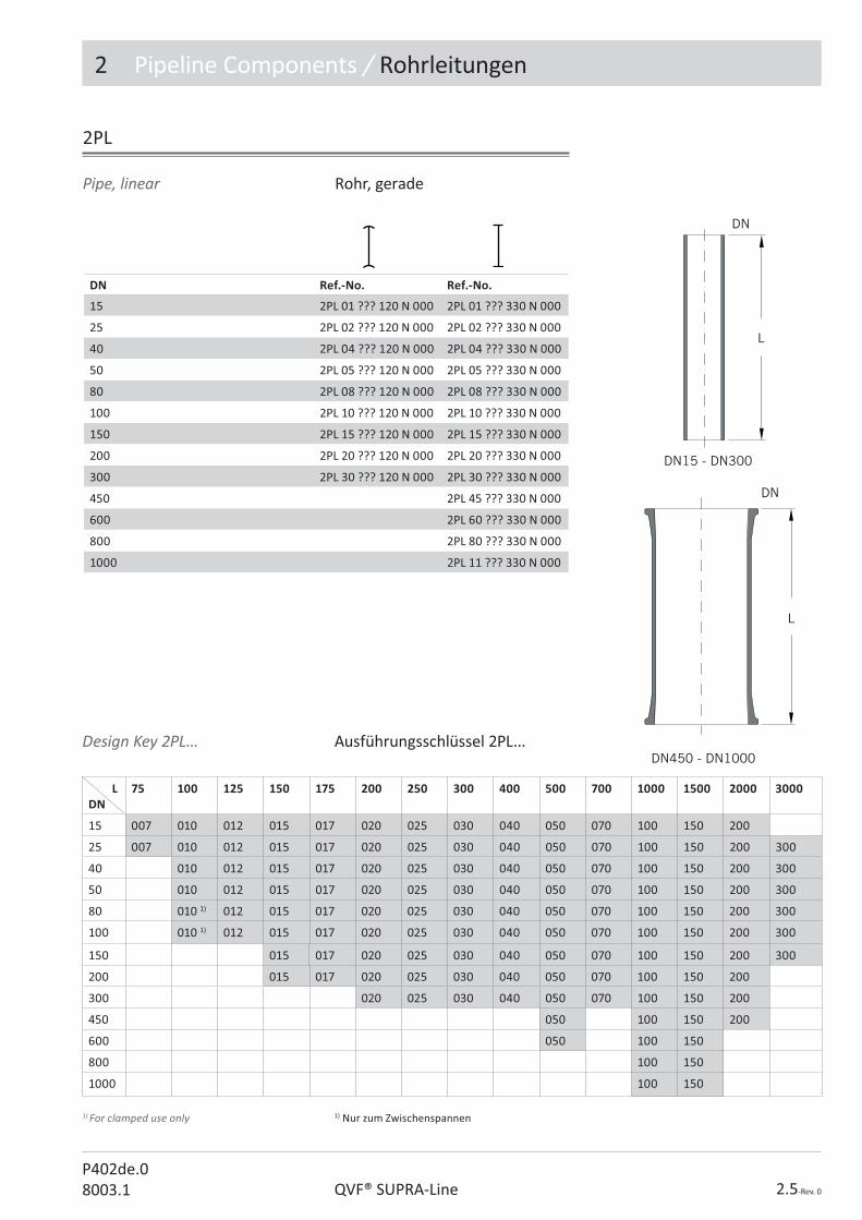
DN Ref.-No. Ref.-No.
15 2PL 01 ??? 120 N 000 2PL 01 ??? 330 N 000
25 2PL 02 ??? 120 N 000 2PL 02 ??? 330 N 000
40 2PL 04 ??? 120 N 000 2PL 04 ??? 330 N 000
50 2PL 05 ??? 120 N 000 2PL 05 ??? 330 N 000
80 2PL 08 ??? 120 N 000 2PL 08 ??? 330 N 000
100 2PL 10 ??? 120 N 000 2PL 10 ??? 330 N 000
150 2PL 15 ??? 120 N 000 2PL 15 ??? 330 N 000
200 2PL 20 ??? 120 N 000 2PL 20 ??? 330 N 000
300 2PL 30 ??? 120 N 000 2PL 30 ??? 330 N 000
450 2PL 45 ??? 330 N 000
600 2PL 60 ??? 330 N 000
800 2PL 80 ??? 330 N 000
1000 2PL 11 ??? 330 N 000
Pipe, linear Rohr, gerade
2PL
Design Key 2PL... Ausführungsschlüssel 2PL...
1) For clamped use only 1) Nur zum Zwischenspannen

2 Pipeline Components / Rohrleitungen
2.6-Rev. 0 QVF® SUPRA-LineP402de.0
8003.1
DN L Ref.-No. Ref.-No.
15 50 2PC 01 090 120 N 000 2PC 01 090 330 N 000
25 100 2PC 02 090 120 N 000 2PC 02 090 330 N 000
40 150 2PC 04 090 120 N 000 2PC 04 090 330 N 000
50 150 2PC 05 090 120 N 000 2PC 05 090 330 N 000
80 200 2PC 08 090 120 N 000 2PC 08 090 330 N 000
100 250 2PC 10 090 120 N 000 2PC 10 090 330 N 000
150 250 2PC 15 090 120 N 000 2PC 15 090 330 N 000
200 300 2PC 20 090 120 N 000 2PC 20 090 330 N 000
300 400 2PC 30 090 120 N 000 2PC 30 090 330 N 000
DN L Ref.-No.
15 50 2PC 01 080 330 N 000
25 100 2PC 02 080 330 N 000
40 150 2PC 04 080 330 N 000
50 150 2PC 05 080 330 N 000
80 200 2PC 08 080 330 N 000
100 250 2PC 10 080 330 N 000
Pipe, curved 90° Rohr, gebogen 90°
Pipe, curved 80° Rohr, gebogen 80°
2PC...090
2PC...080
2.7-Rev. 0QVF® SUPRA-LineP402de.08003.1
2 Pipeline Components / Rohrleitungen
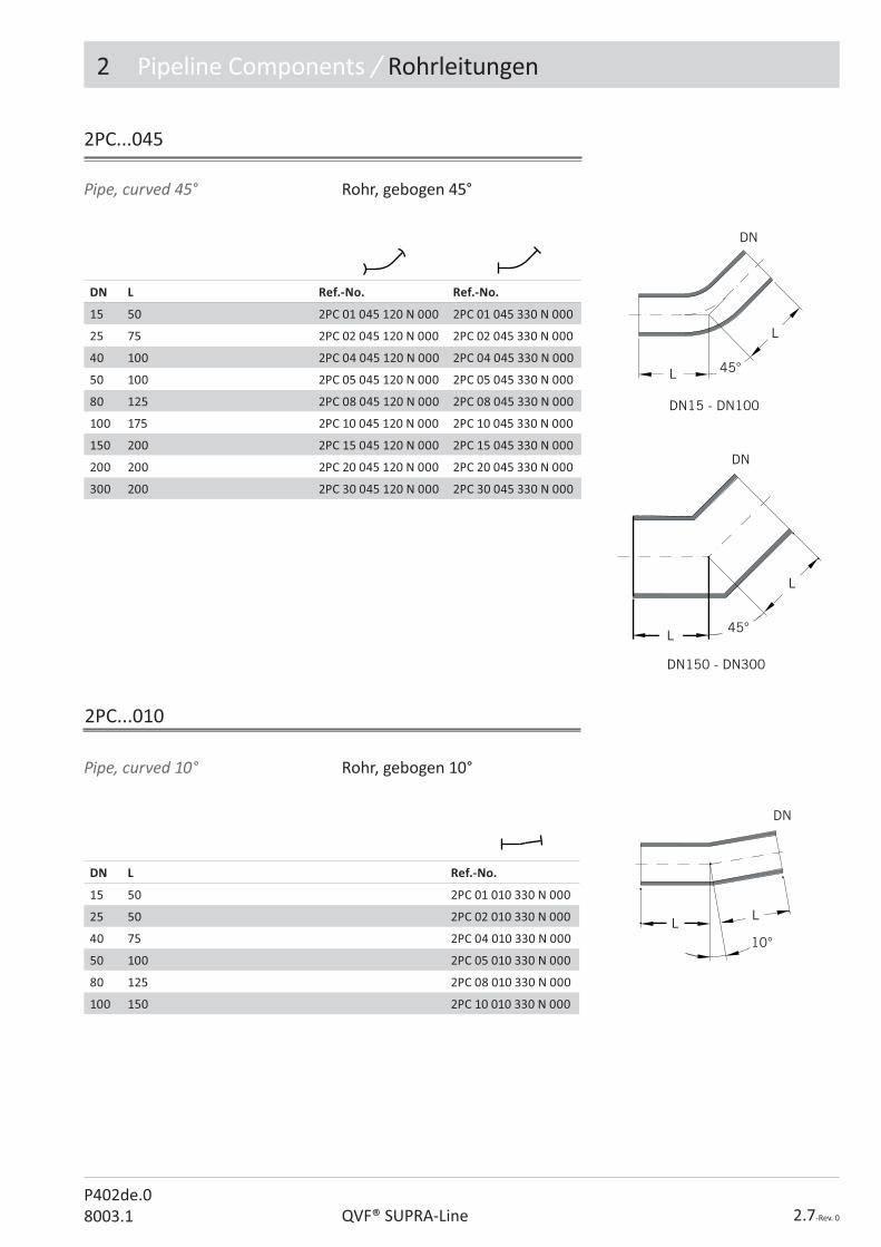
DN L Ref.-No. Ref.-No.
15 50 2PC 01 045 120 N 000 2PC 01 045 330 N 000
25 75 2PC 02 045 120 N 000 2PC 02 045 330 N 000
40 100 2PC 04 045 120 N 000 2PC 04 045 330 N 000
50 100 2PC 05 045 120 N 000 2PC 05 045 330 N 000
80 125 2PC 08 045 120 N 000 2PC 08 045 330 N 000
100 175 2PC 10 045 120 N 000 2PC 10 045 330 N 000
150 200 2PC 15 045 120 N 000 2PC 15 045 330 N 000
200 200 2PC 20 045 120 N 000 2PC 20 045 330 N 000
300 200 2PC 30 045 120 N 000 2PC 30 045 330 N 000
DN L Ref.-No.
15 50 2PC 01 010 330 N 000
25 50 2PC 02 010 330 N 000
40 75 2PC 04 010 330 N 000
50 100 2PC 05 010 330 N 000
80 125 2PC 08 010 330 N 000
100 150 2PC 10 010 330 N 000
Pipe, curved 45° Rohr, gebogen 45°
Pipe, curved 10° Rohr, gebogen 10°
2PC...045
2PC...010

2 Pipeline Components / Rohrleitungen
2.8-Rev. 0 QVF® SUPRA-LineP402de.0
8003.1
Rohr, gebogen 180°, Abzweig, symmetrisch
Pipe, curved 180°, neck, equal
DN L L1 Ref.-No. Ref.-No.
15 75 75 2PC 01 180 120 N 000 2PC 01 180 330 N 000
25 150 150 2PC 02 180 120 N 000 2PC 02 180 330 N 000
40 150 150 2PC 04 180 120 N 000 2PC 04 180 330 N 000
50 150 150 2PC 05 180 120 N 000 2PC 05 180 330 N 000
80 200 200 2PC 08 180 120 N 000 2PC 08 180 330 N 000
100 200 225 2PC 10 180 120 N 000 2PC 10 180 330 N 000
Pipe, curved 180° Rohr, gebogen 180°
DN L L1 Ref.-No. Ref.-No.
15 125 75 2PC 01 180 121 N 000 2PC 01 180 333 N 000
25 225 150 2PC 02 180 121 N 000 2PC 02 180 333 N 000
40 250 150 2PC 04 180 121 N 000 2PC 04 180 333 N 000
50 250 150 2PC 05 180 121 N 000 2PC 05 180 333 N 000
2PC...180
2PC...180 121/333
2.9-Rev. 0QVF® SUPRA-LineP402de.08003.1
2 Pipeline Components / Rohrleitungen
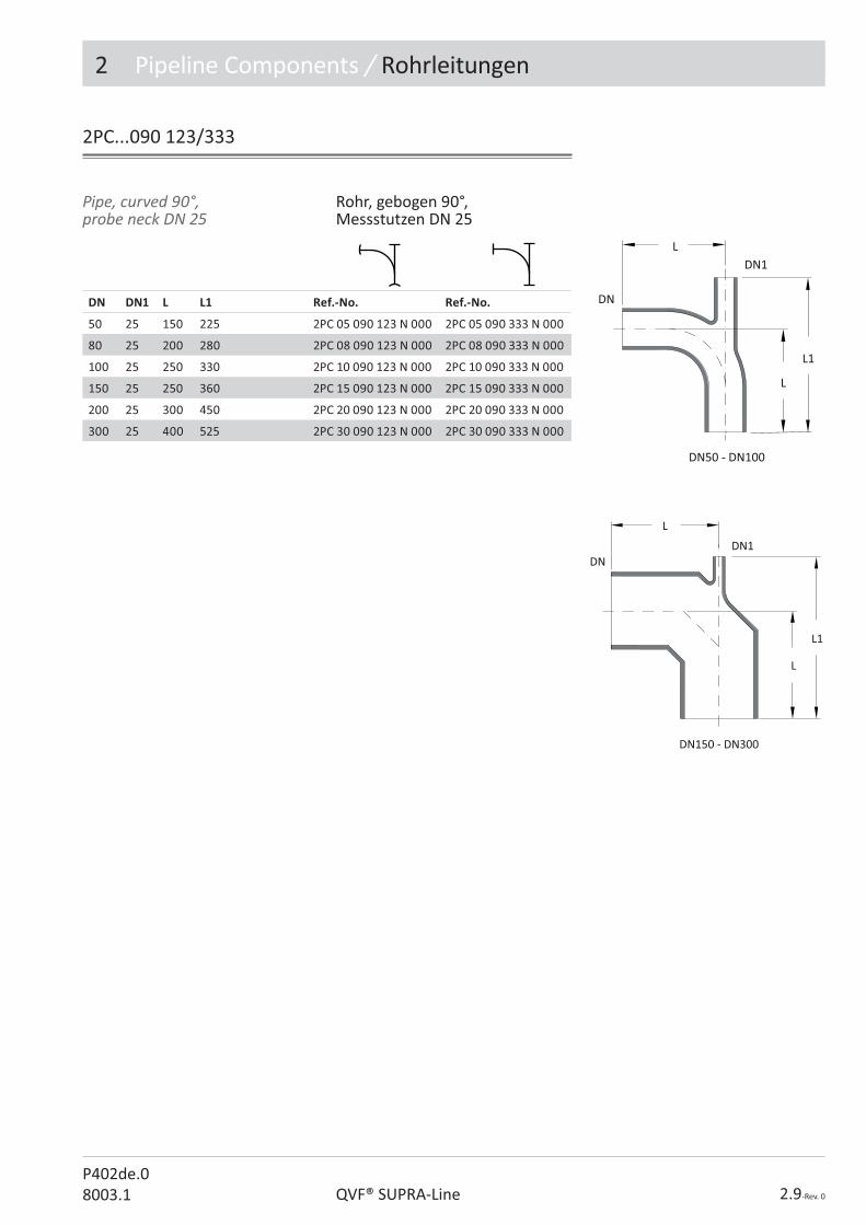
DN DN1 L L1 Ref.-No. Ref.-No.
50 25 150 225 2PC 05 090 123 N 000 2PC 05 090 333 N 000
80 25 200 280 2PC 08 090 123 N 000 2PC 08 090 333 N 000
100 25 250 330 2PC 10 090 123 N 000 2PC 10 090 333 N 000
150 25 250 360 2PC 15 090 123 N 000 2PC 15 090 333 N 000
200 25 300 450 2PC 20 090 123 N 000 2PC 20 090 333 N 000
300 25 400 525 2PC 30 090 123 N 000 2PC 30 090 333 N 000
Pipe, curved 90°, probe neck DN 25
Rohr, gebogen 90°, Messstutzen DN 25
2PC...090 123/333

2 Pipeline Components / Rohrleitungen
2.10-Rev. 0 QVF® SUPRA-LineP402de.0
8003.1
Joint, T-form, equal Anschluss, T-Form, symmetrisch
Pipe, end cap Rohr, Abschluss
2PE
DN L Ref.-No. Ref.-No. Ref.-No.
15 60 2PE 01 000 100 N 000 2PE 01 000 200 N 000 2PE 01 000 300 N 000
25 60 2PE 02 000 100 N 000 2PE 02 000 200 N 000 2PE 02 000 300 N 000
40 70 2PE 04 000 100 N 000 2PE 04 000 200 N 000 2PE 04 000 300 N 000
50 90 2PE 05 000 100 N 000 2PE 05 000 200 N 000 2PE 05 000 300 N 000
80 90 2PE 08 000 100 N 000 2PE 08 000 200 N 000 2PE 08 000 300 N 000
100 90 2PE 10 000 100 N 000 2PE 10 000 200 N 000 2PE 10 000 300 N 000
150 115 2PE 15 000 100 N 000 2PE 15 000 200 N 000 2PE 15 000 300 N 000
DN L Ref.-No. Ref.-No. Ref.-No.
15 50 2JT 01 000 121 N 000 2JT 01 000 122 N 000 2JT 01 000 333 N 000
25 100 2JT 02 000 121 N 000 2JT 02 000 122 N 000 2JT 02 000 333 N 000
40 150 2JT 04 000 121 N 000 2JT 04 000 122 N 000 2JT 04 000 333 N 000
50 150 2JT 05 000 121 N 000 2JT 05 000 122 N 000 2JT 05 000 333 N 000
80 200 2JT 08 000 121 N 000 2JT 08 000 122 N 000 2JT 08 000 333 N 000
100 250 2JT 10 000 121 N 000 2JT 10 000 122 N 000 2JT 10 000 333 N 000
150 250 2JT 15 000 121 N 000 2JT 15 000 122 N 000 2JT 15 000 333 N 000
200 300 2JT 20 000 121 N 000 2JT 20 000 122 N 000 2JT 20 000 333 N 000
300 400 2JT 30 000 121 N 000 2JT 30 000 122 N 000 2JT 30 000 333 N 000
2JT...000

2.11-Rev. 0QVF® SUPRA-LineP402de.08003.1
2 Pipeline Components / Rohrleitungen
Joint, T-form, unequal Anschluss, T-Form, unsymmetrisch
DN DN1 L L1 Ref.-No. Ref.-No.
25 15 150 75 2JT 02 001 121 N 000 2JT 02 001 333 N 000
40 25 200 75 2JT 04 002 121 N 000 2JT 04 002 333 N 000
50 25 200 100 2JT 05 002 121 N 000 2JT 05 002 333 N 000
50 40 200 100 2JT 05 004 121 N 000 2JT 05 004 333 N 000
80 25 200 100 2JT 08 002 121 N 000 2JT 08 002 333 N 000
80 40 250 100 2JT 08 004 121 N 000 2JT 08 004 333 N 000
80 50 250 100 2JT 08 005 121 N 000 2JT 08 005 333 N 000
100 25 200 125 2JT 10 002 121 N 000 2JT 10 002 333 N 000
100 40 250 125 2JT 10 004 121 N 000 2JT 10 004 333 N 000
100 50 250 125 2JT 10 005 121 N 000 2JT 10 005 333 N 000
100 80 300 125 2JT 10 008 121 N 000 2JT 10 008 333 N 000
150 25 200 150 2JT 15 002 121 N 000 2JT 15 002 333 N 000
150 40 250 150 2JT 15 004 121 N 000 2JT 15 004 333 N 000
150 50 250 150 2JT 15 005 121 N 000 2JT 15 005 333 N 000
150 80 300 150 2JT 15 008 121 N 000 2JT 15 008 333 N 000
150 100 300 150 2JT 15 010 121 N 000 2JT 15 010 333 N 000
200 25 200 175 2JT 20 002 121 N 000 2JT 20 002 333 N 000
200 40 250 175 2JT 20 004 121 N 000 2JT 20 004 333 N 000
200 50 250 175 2JT 20 005 121 N 000 2JT 20 005 333 N 000
200 80 300 175 2JT 20 008 121 N 000 2JT 20 008 333 N 000
200 100 300 175 2JT 20 010 121 N 000 2JT 20 010 333 N 000
200 150 400 225 2JT 20 015 121 N 000 2JT 20 015 333 N 000
300 25 300 225 2JT 30 002 121 N 000 2JT 30 002 333 N 000
300 40 400 225 2JT 30 004 121 N 000 2JT 30 004 333 N 000
300 50 400 225 2JT 30 005 121 N 000 2JT 30 005 333 N 000
300 80 400 225 2JT 30 008 121 N 000 2JT 30 008 333 N 000
300 100 400 225 2JT 30 010 121 N 000 2JT 30 010 333 N 000
300 150 500 275 2JT 30 015 121 N 000 2JT 30 015 333 N 000
300 200 600 275 2JT 30 020 121 N 000 2JT 30 020 333 N 000
450 80 400 325 2JT 45 008 333 N 000
450 150 500 375 2JT 45 015 333 N 000
600 80 600 400 2JT 60 008 333 N 000*
600 150 600 450 2JT 60 015 333 N 000*
600 300 800 500 2JT 60 030 333 N 000*
800 150 700 575 2JT 80 015 333 N 000*
800 300 1000 650 2JT 80 030 333 N 000*
1000 150 700 675 2JT 11 015 333 N 000*
1000 300 1000 750 2JT 11 030 333 N 000*
2JT...0??
*Reduced pressure PS (bar g) / *Reduzierter Betriebsüberdruck PS (bar)
0,9
0,8
0,7
0,8
0,6
0,7
0,6
2 Pipeline Components / Rohrleitungen
2.12-Rev. 0 QVF® SUPRA-LineP402de.0
8003.1
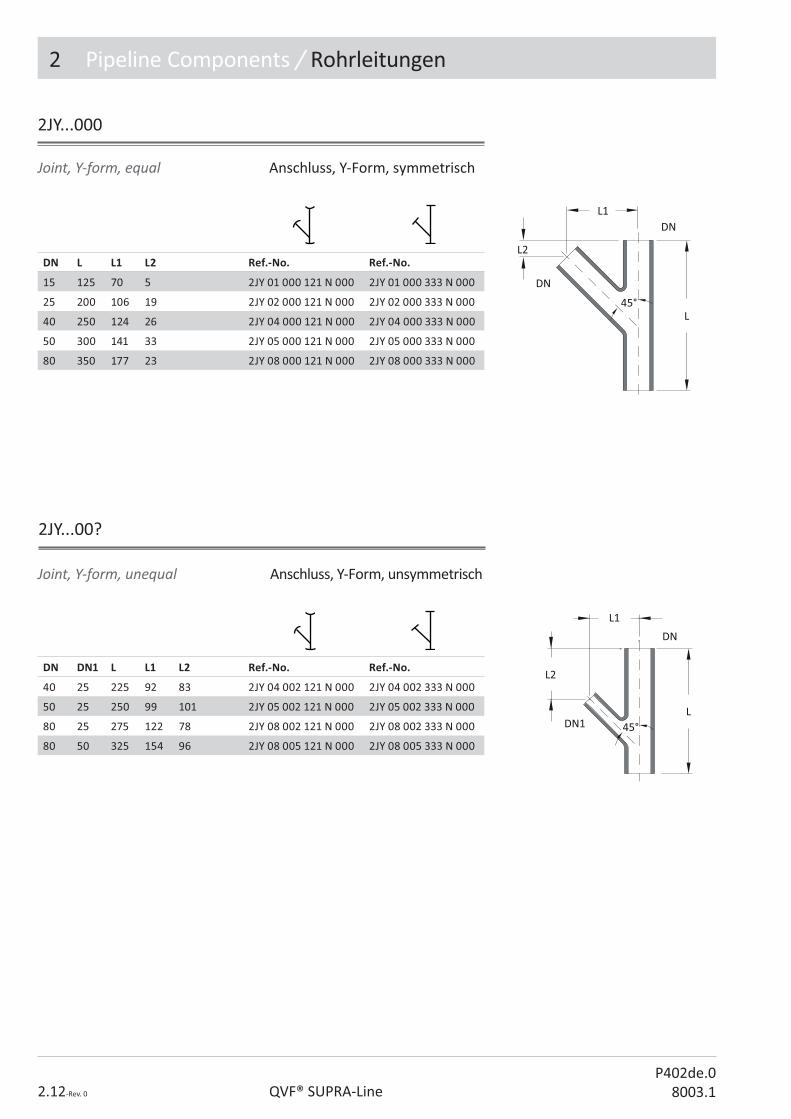
Joint, Y-form, unequal Anschluss, Y-Form, unsymmetrisch
Joint, Y-form, equal Anschluss, Y-Form, symmetrisch
DN L L1 L2 Ref.-No. Ref.-No.
15 125 70 5 2JY 01 000 121 N 000 2JY 01 000 333 N 000
25 200 106 19 2JY 02 000 121 N 000 2JY 02 000 333 N 000
40 250 124 26 2JY 04 000 121 N 000 2JY 04 000 333 N 000
50 300 141 33 2JY 05 000 121 N 000 2JY 05 000 333 N 000
80 350 177 23 2JY 08 000 121 N 000 2JY 08 000 333 N 000
DN DN1 L L1 L2 Ref.-No. Ref.-No.
40 25 225 92 83 2JY 04 002 121 N 000 2JY 04 002 333 N 000
50 25 250 99 101 2JY 05 002 121 N 000 2JY 05 002 333 N 000
80 25 275 122 78 2JY 08 002 121 N 000 2JY 08 002 333 N 000
80 50 325 154 96 2JY 08 005 121 N 000 2JY 08 005 333 N 000
2JY...000
2JY...00?

2.13-Rev. 0QVF® SUPRA-LineP402de.08003.1
2 Pipeline Components / Rohrleitungen
Joint, X-form, equal Anschluss, X-Form, symmetrisch
2JX
DN L Ref.-No. Ref.-No.
15 50 2JX 01 000 210 N 000 2JX 01 000 330 N 000
25 100 2JX 02 000 210 N 000 2JX 02 000 330 N 000
40 150 2JX 04 000 210 N 000 2JX 04 000 330 N 000
50 150 2JX 05 000 210 N 000 2JX 05 000 330 N 000
80 200 2JX 08 000 210 N 000 2JX 08 000 330 N 000
100 250 2JX 10 000 210 N 000 2JX 10 000 330 N 000
150 250 2JX 15 000 210 N 000 2JX 15 000 330 N 000
Reducer, concentric Reduzierung, konzentrisch
DN DN1 L Ref.-No. Ref.-No. Ref.-No.
25 15 100 2RC 02 001 310 N 000 2RC 02 001 210 N 000 2RC 02 001 330 N 000
40 15 100 2RC 04 001 310 N 000 2RC 04 001 210 N 000 2RC 04 001 330 N 000
40 25 100 2RC 04 002 310 N 000 2RC 04 002 210 N 000 2RC 04 002 330 N 000
50 15 100 2RC 05 001 310 N 000 2RC 05 001 210 N 000 2RC 05 001 330 N 000
50 25 100 2RC 05 002 310 N 000 2RC 05 002 210 N 000 2RC 05 002 330 N 000
50 40 100 2RC 05 004 310 N 000 2RC 05 004 210 N 000 2RC 05 004 330 N 000
80 25 125 2RC 08 002 310 N 000 2RC 08 002 210 N 000 2RC 08 002 330 N 000
80 40 125 2RC 08 004 310 N 000 2RC 08 004 210 N 000 2RC 08 004 330 N 000
80 50 125 2RC 08 005 310 N 000 2RC 08 005 210 N 000 2RC 08 005 330 N 000
100 25 150 2RC 10 002 310 N 000 2RC 10 002 210 N 000 2RC 10 002 330 N 000
100 40 150 2RC 10 004 310 N 000 2RC 10 004 210 N 000 2RC 10 004 330 N 000
100 50 150 2RC 10 005 310 N 000 2RC 10 005 210 N 000 2RC 10 005 330 N 000
100 80 150 2RC 10 008 310 N 000 2RC 10 008 210 N 000 2RC 10 008 330 N 000
150 25 200 2RC 15 002 310 N 000 2RC 15 002 210 N 000 2RC 15 002 330 N 000
150 40 200 2RC 15 004 310 N 000 2RC 15 004 210 N 000 2RC 15 004 330 N 000
150 50 200 2RC 15 005 310 N 000 2RC 15 005 210 N 000 2RC 15 005 330 N 000
150 80 200 2RC 15 008 310 N 000 2RC 15 008 210 N 000 2RC 15 008 330 N 000
150 100 200 2RC 15 010 310 N 000 2RC 15 010 210 N 000 2RC 15 010 330 N 000
2RC
2 Pipeline Components / Rohrleitungen
2.14-Rev. 0 QVF® SUPRA-LineP402de.0
8003.1
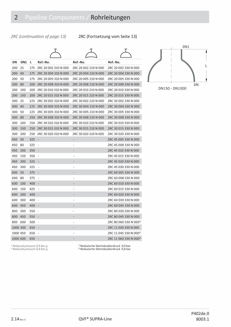
DN DN1 L Ref.-No. Ref.-No. Ref.-No.
200 25 175 2RC 20 002 310 N 000 2RC 20 002 210 N 000 2RC 20 002 330 N 000
200 40 175 2RC 20 004 310 N 000 2RC 20 004 210 N 000 2RC 20 004 330 N 000
200 50 175 2RC 20 005 310 N 000 2RC 20 005 210 N 000 2RC 20 005 330 N 000
200 80 200 2RC 20 008 310 N 000 2RC 20 008 210 N 000 2RC 20 008 330 N 000
200 100 200 2RC 20 010 310 N 000 2RC 20 010 210 N 000 2RC 20 010 330 N 000
200 150 200 2RC 20 015 310 N 000 2RC 20 015 210 N 000 2RC 20 015 330 N 000
300 25 225 2RC 30 002 310 N 000 2RC 30 002 210 N 000 2RC 30 002 330 N 000
300 40 225 2RC 30 004 310 N 000 2RC 30 004 210 N 000 2RC 30 004 330 N 000
300 50 225 2RC 30 005 310 N 000 2RC 30 005 210 N 000 2RC 30 005 330 N 000
300 80 250 2RC 30 008 310 N 000 2RC 30 008 210 N 000 2RC 30 008 330 N 000
300 100 250 2RC 30 010 310 N 000 2RC 30 010 210 N 000 2RC 30 010 330 N 000
300 150 250 2RC 30 015 310 N 000 2RC 30 015 210 N 000 2RC 30 015 330 N 000
300 200 250 2RC 30 020 310 N 000 2RC 30 020 210 N 000 2RC 30 020 330 N 000
450 50 325 - - 2RC 45 005 330 N 000
450 80 325 - - 2RC 45 008 330 N 000
450 100 350 - - 2RC 45 010 330 N 000
450 150 350 - - 2RC 45 015 330 N 000
450 200 325 - - 2RC 45 020 330 N 000
450 300 325 - - 2RC 45 030 330 N 000
600 50 375 - - 2RC 60 005 330 N 000
600 80 375 - - 2RC 60 008 330 N 000
600 100 400 - - 2RC 60 010 330 N 000
600 150 425 - - 2RC 60 015 330 N 000
600 200 400 - - 2RC 60 020 330 N 000
600 300 400 - - 2RC 60 030 330 N 000
600 450 400 - - 2RC 60 045 330 N 000
800 300 550 - - 2RC 80 030 330 N 000
800 450 550 - - 2RC 80 045 330 N 000
800 600 500 - - 2RC 80 060 330 N 0001)
1000 300 650 - - 2RC 11 030 330 N 000
1000 450 650 - - 2RC 11 045 330 N 0002)
1000 600 650 - - 2RC 11 060 330 N 0002)
2RC (con� nua� on of page 13) 2RC (Fortsetzung vom Seite 13)
1) Reduced pressure 0,9 bar g 2) Reduced pressure 0,8 bar g
1) Reduzierter Betriebsüberdruck 0,9 bar 2) Reduzierter Betriebsüberdruck 0,8 bar

2.15-Rev. 0QVF® SUPRA-LineP402de.08003.1
2 Pipeline Components / Rohrleitungen
Reducer, bend Reduzierung, Bogen
2RB
2RE
DN DN1 L L1 Ref.-No. Ref.-No.
25 15 100 5 2RE 02 001 210 N 000 2RE 02 001 330 N 000
40 25 100 7 2RE 04 002 210 N 000 2RE 04 002 330 N 000
50 25 100 13 2RE 05 002 210 N 000 2RE 05 002 330 N 000
50 40 100 7 2RE 05 004 210 N 000 2RE 05 004 330 N 000
80 25 125 25 2RE 08 002 210 N 000 2RE 08 002 330 N 000
80 40 125 19 2RE 08 004 210 N 000 2RE 08 004 330 N 000
80 50 125 12 2RE 08 005 210 N 000 2RE 08 005 330 N 000
100 25 150 38 2RE 10 002 210 N 000 2RE 10 002 330 N 000
100 40 150 32 2RE 10 004 210 N 000 2RE 10 004 330 N 000
100 50 150 25 2RE 10 005 210 N 000 2RE 10 005 330 N 000
100 80 150 12 2RE 10 008 210 N 000 2RE 10 008 330 N 000
150 50 175 45 2RE 15 005 210 N 000 2RE 15 005 330 N 000
150 80 175 32 2RE 15 008 210 N 000 2RE 15 008 330 N 000
150 100 175 20 2RE 15 010 210 N 000 2RE 15 010 330 N 000
DN DN1 L L1 Ref.-No. Ref.-No.
25 15 100 50 2RB 02 001 210 N 000 2RB 02 001 330 N 000
40 25 125 100 2RB 04 002 210 N 000 2RB 04 002 330 N 000
50 25 150 100 2RB 05 002 210 N 000 2RB 05 002 330 N 000
50 40 150 150 2RB 05 004 210 N 000 2RB 05 004 330 N 000
80 50 150 150 2RB 08 005 210 N 000 2RB 08 005 330 N 000
100 50 200 150 2RB 10 005 210 N 000 2RB 10 005 330 N 000
100 80 200 175 2RB 10 008 210 N 000 2RB 10 008 330 N 000
150 50 200 150 2RB 15 005 210 N 000 2RB 15 005 330 N 000
150 80 250 175 2RB 15 008 210 N 000 2RB 15 008 330 N 000
200 80 250 175 2RB 20 008 210 N 000 2RB 20 008 330 N 000
300 80 300 175 2RB 30 008 210 N 000 2RB 30 008 330 N 000
300 150 350 250 2RB 30 015 210 N 000 2RB 30 015 330 N 000
Reducer, excentric Reduzierung, exzentrisch
2 Pipeline Components / Rohrleitungen
2.16-Rev. 0 QVF® SUPRA-LineP402de.0
8003.1
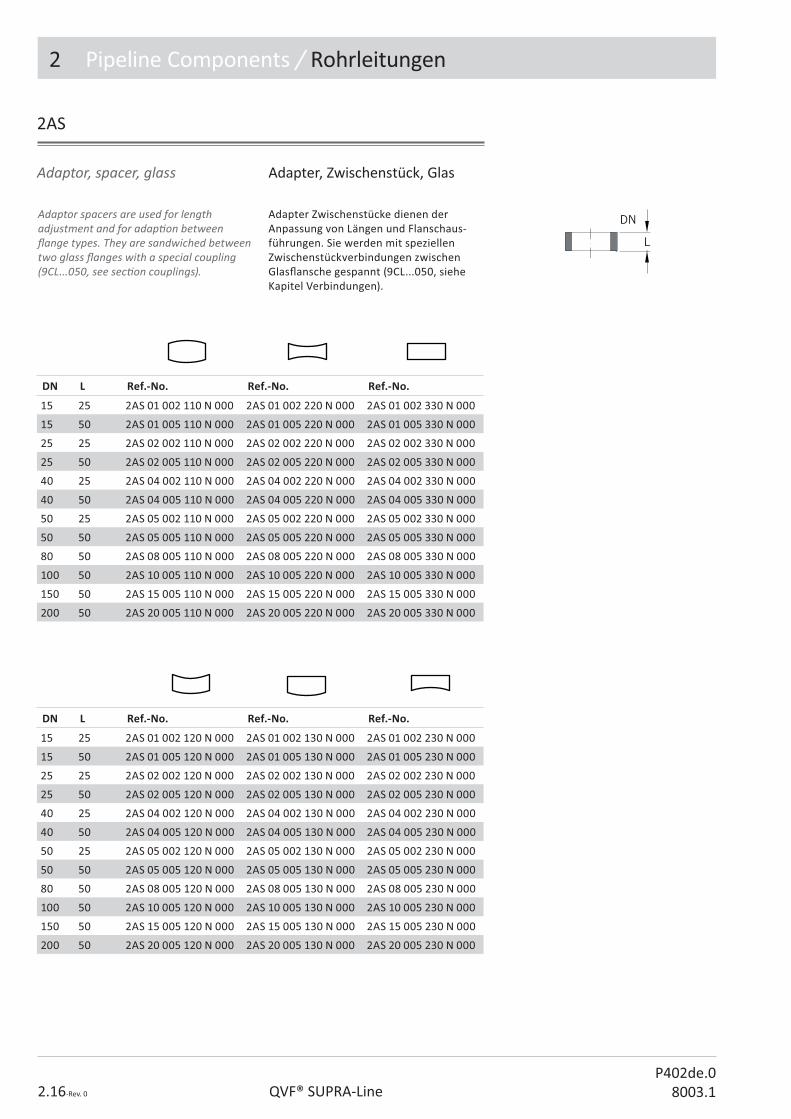
Adaptor, spacer, glass Adapter, Zwischenstück, Glas
DN L Ref.-No. Ref.-No. Ref.-No.
15 25 2AS 01 002 110 N 000 2AS 01 002 220 N 000 2AS 01 002 330 N 000
15 50 2AS 01 005 110 N 000 2AS 01 005 220 N 000 2AS 01 005 330 N 000
25 25 2AS 02 002 110 N 000 2AS 02 002 220 N 000 2AS 02 002 330 N 000
25 50 2AS 02 005 110 N 000 2AS 02 005 220 N 000 2AS 02 005 330 N 000
40 25 2AS 04 002 110 N 000 2AS 04 002 220 N 000 2AS 04 002 330 N 000
40 50 2AS 04 005 110 N 000 2AS 04 005 220 N 000 2AS 04 005 330 N 000
50 25 2AS 05 002 110 N 000 2AS 05 002 220 N 000 2AS 05 002 330 N 000
50 50 2AS 05 005 110 N 000 2AS 05 005 220 N 000 2AS 05 005 330 N 000
80 50 2AS 08 005 110 N 000 2AS 08 005 220 N 000 2AS 08 005 330 N 000
100 50 2AS 10 005 110 N 000 2AS 10 005 220 N 000 2AS 10 005 330 N 000
150 50 2AS 15 005 110 N 000 2AS 15 005 220 N 000 2AS 15 005 330 N 000
200 50 2AS 20 005 110 N 000 2AS 20 005 220 N 000 2AS 20 005 330 N 000
2AS
DN L Ref.-No. Ref.-No. Ref.-No.
15 25 2AS 01 002 120 N 000 2AS 01 002 130 N 000 2AS 01 002 230 N 000
15 50 2AS 01 005 120 N 000 2AS 01 005 130 N 000 2AS 01 005 230 N 000
25 25 2AS 02 002 120 N 000 2AS 02 002 130 N 000 2AS 02 002 230 N 000
25 50 2AS 02 005 120 N 000 2AS 02 005 130 N 000 2AS 02 005 230 N 000
40 25 2AS 04 002 120 N 000 2AS 04 002 130 N 000 2AS 04 002 230 N 000
40 50 2AS 04 005 120 N 000 2AS 04 005 130 N 000 2AS 04 005 230 N 000
50 25 2AS 05 002 120 N 000 2AS 05 002 130 N 000 2AS 05 002 230 N 000
50 50 2AS 05 005 120 N 000 2AS 05 005 130 N 000 2AS 05 005 230 N 000
80 50 2AS 08 005 120 N 000 2AS 08 005 130 N 000 2AS 08 005 230 N 000
100 50 2AS 10 005 120 N 000 2AS 10 005 130 N 000 2AS 10 005 230 N 000
150 50 2AS 15 005 120 N 000 2AS 15 005 130 N 000 2AS 15 005 230 N 000
200 50 2AS 20 005 120 N 000 2AS 20 005 130 N 000 2AS 20 005 230 N 000
Adaptor spacers are used for length adjustment and for adap� on between � ange types. They are sandwiched between two glass � anges with a special coupling (9CL...050, see sec� on couplings).
Adapter Zwischenstücke dienen der Anpassung von Längen und Flanschaus-führungen. Sie werden mit speziellen Zwischenstückverbindungen zwischen Glas� ansche gespannt (9CL...050, siehe Kapitel Verbindungen).

2.17-Rev. 0QVF® SUPRA-LineP402de.08003.1
2 Pipeline Components / Rohrleitungen
Adaptor, pipe Adapter, Rohr
DN L Ref.-No. Ref.-No.
15 100 2AP 01 010 130 N 000 2AP 01 010 230 N 000
25 100 2AP 02 010 130 N 000 2AP 02 010 230 N 000
40 100 2AP 04 010 130 N 000 2AP 04 010 230 N 000
50 100 2AP 05 010 130 N 000 2AP 05 010 230 N 000
80 125 2AP 08 012 130 N 000 2AP 08 012 230 N 000
100 125 2AP 10 012 130 N 000 2AP 10 012 230 N 000
150 150 2AP 15 015 130 N 000 2AP 15 015 230 N 000
200 150 2AP 20 015 130 N 000 2AP 20 015 230 N 000
300 200 2AP 30 020 130 N 000 2AP 30 020 230 N 000
DN L Ref.-No. Ref.-No.
15 100 2AP 01 010 110 N 000 2AP 01 010 220 N 000
25 100 2AP 02 010 110 N 000 2AP 02 010 220 N 000
40 100 2AP 04 010 110 N 000 2AP 04 010 220 N 000
50 100 2AP 05 010 110 N 000 2AP 05 010 220 N 000
80 125 2AP 08 012 110 N 000 2AP 08 012 220 N 000
100 125 2AP 10 012 110 N 000 2AP 10 012 220 N 000
150 150 2AP 15 015 110 N 000 2AP 15 015 220 N 000
200 150 2AP 20 015 110 N 000 2AP 20 015 220 N 000
300 200 2AP 30 020 110 N 000 2AP 30 020 220 N 000
2AP
For the connec� on of di� erent � ange types short adaptor pipes with two � ange ends are used.
Zur Anpassung an unterschiedliche Flansch-ausführungen werden kurze Adapterrohre mit zwei Flanschenden eingesetzt.
2 Pipeline Components / Rohrleitungen
2.18-Rev. 0 QVF® SUPRA-LineP402de.0
8003.1
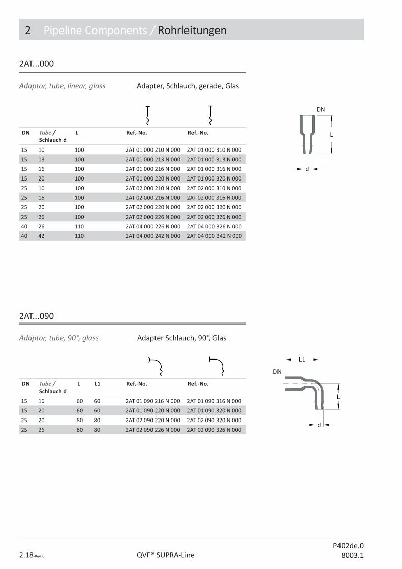
Adapter Schlauch, 90°, GlasAdaptor, tube, 90°, glass
Adaptor, tube, linear, glass Adapter, Schlauch, gerade, Glas
DN Tube / Schlauch d
L Ref.-No. Ref.-No.
15 10 100 2AT 01 000 210 N 000 2AT 01 000 310 N 000
15 13 100 2AT 01 000 213 N 000 2AT 01 000 313 N 000
15 16 100 2AT 01 000 216 N 000 2AT 01 000 316 N 000
15 20 100 2AT 01 000 220 N 000 2AT 01 000 320 N 000
25 10 100 2AT 02 000 210 N 000 2AT 02 000 310 N 000
25 16 100 2AT 02 000 216 N 000 2AT 02 000 316 N 000
25 20 100 2AT 02 000 220 N 000 2AT 02 000 320 N 000
25 26 100 2AT 02 000 226 N 000 2AT 02 000 326 N 000
40 26 110 2AT 04 000 226 N 000 2AT 04 000 326 N 000
40 42 110 2AT 04 000 242 N 000 2AT 04 000 342 N 000
DN Tube / Schlauch d
L L1 Ref.-No. Ref.-No.
15 16 60 60 2AT 01 090 216 N 000 2AT 01 090 316 N 000
15 20 60 60 2AT 01 090 220 N 000 2AT 01 090 320 N 000
25 20 80 80 2AT 02 090 220 N 000 2AT 02 090 320 N 000
25 26 80 80 2AT 02 090 226 N 000 2AT 02 090 326 N 000
2AT...090
2AT...000

P403e.08003.1
������������� �������
2. Pipeline Components
3. VALVES AND FILTERS
4. Vessels
5. Heat Exchangers
6. Column Components
������������
8. Measurement and Control
9. Couplings
10. Structures and Supports
The Component System

3 Valves & Filters / Armaturen
P403de.08003.1QVF® SUPRA-Line3.2-Rev. 0
Contents / Inhaltsverzeichnis
Ref.-No. Reference Ar� kel-Bezeichnung Page / Seite
3VO Valve, on/o� , angled, manual Ven� l, AUF/ZU, Eck, handbetä� gt 4
3VO Valve, on/o� , straight through, manual Ven� l, AUF/ZU, Durchgang, handbetä� gt 4
3VO Valve, on/o� , angled, pneuma� cally actuated, Samson
Ven� l, AUF/ZU, Eck, pneuma� sch betä� gt, Samson 6
3VO Valve, on/o� , angled, pneuma� cally actuated, Flowserve
Ven� l, AUF/ZU, Eck, pneuma� sch betä� gt, Flowserve 6
3VO Valve, on/o� , straight through, pneuma� cally actuated, Samson
Ven� l, AUF/ZU, Durchgang, pneuma� sch betä� gt, Samson
7
3VO Valve, on/o� , straight through, pneuma� cally actuated, Flowserve
Ven� l, AUF/ZU, Durchgang, pneuma� sch betä� gt, Flowserve
7
3BG Ball valve, glass, manual Kugelhahn, Glas, handbetä� gt 8
3BC Ball valve, compact, manual Kugelhahn, Kompakt, handbetä� gt 9
3BG Ball valve, glass, pneuma� cally actuated Kugelhahn, Glas, pneuma� sch betä� gt 11
3BC Ball valve, pneuma� cally actuated, compact Kugelhahn, pneuma� sch betä� gt, Kompakt 11
3FB Flap, bu� er� y type Klappe 12
3VS Valve, control, Samson actuator Ven� l, Regel, Samson-Stellantrieb 14
3VF Valve, control, Flowserve actuator Ven� l, Regel, Flowserve-Stellantrieb 15
3VR Valve, relief Ven� l, Sicherheit 16
3VL Valve, loading Ven� l, Druckhalte 17
3NB Valve, non-return, ball valve Ven� l, Rückschlag, Kugel 18
3NF Valve, non-return, � ap, glass, ver� cal Ven� l, Rückschlag, Klappe, Glas, ver� kal 19
3NF Valve, non-return, � ap, glass, horizontal Ven� l, Rückschlag, Klappe, Glas, horizontal 19
3NF Valve, non-return, � ap, PTFE Ven� l, Rückschlag, Klappe, PTFE 20
3VD Valve, drain Ven� l, Auslauf 21
3VV Valve, vent Ven� l, Belü� ung 21
3VA Valve, adjustable, over� ow Ven� l, Überlauf, verstellbar 22
3VT Valve, three way Ven� l, Dreiwege 23
3VP Valve, sampling, no pressure Ven� l, Probenahme, drucklos 24
3VP Valve, sampling, vacuum Ven� l, Probenahme, Vakuum 24
3FP Filter, pipeline Filter, Rohrleitung 25
3FT Filter, trap, coarse Filter, Schmutzfänger, grob 26
3FT Filter, trap, � ne Filter, Schmutzfänger, fein 26
Technical data are subject to change. All rights reserved. Copyright © De Dietrich Process Systems GmbH.
Technische Änderungen und Irrtümer vor-behalten. Copyright © De Dietrich Process Systems GmbH .
3 Valves & Filters / Armaturen
3.3-Rev. 0QVF® SUPRA-LineP403de.08003.1
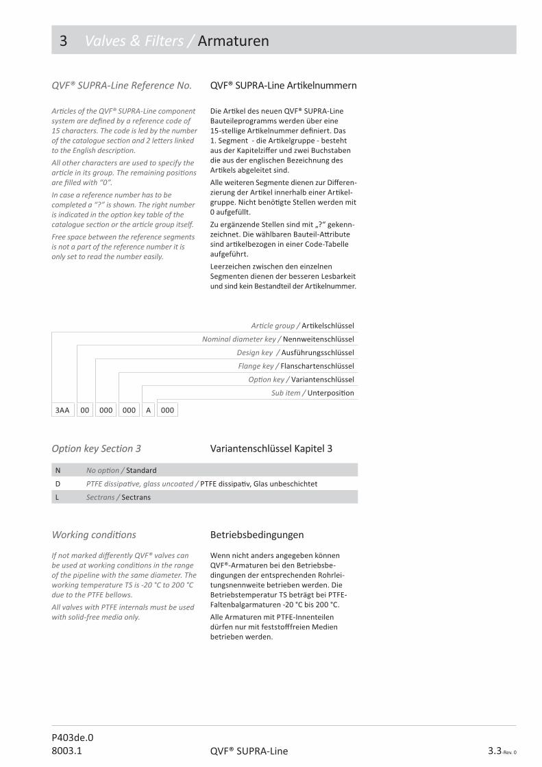
Option key Section 3Option key Section 3 Variantenschlüssel Kapitel 3Variantenschlüssel Kapitel 3
N No op� on / Standard
D PTFE dissipa� ve, glass uncoated / PTFE dissipa� v, Glas unbeschichtet
L Sectrans / Sectrans
Working condi� ons Betriebsbedingungen
If not marked di� erently QVF® valves can be used at working condi� ons in the range of the pipeline with the same diameter. The working temperature TS is -20 °C to 200 °C due to the PTFE bellows. All valves with PTFE internals must be used with solid-free media only.
Wenn nicht anders angegeben können QVF®-Armaturen bei den Betriebsbe-dingungen der entsprechenden Rohrlei-tungsnennweite betrieben werden. Die Betriebstemperatur TS beträgt bei PTFE-Faltenbalgarmaturen -20 °C bis 200 °C.
Alle Armaturen mit PTFE-Innenteilen dürfen nur mit feststo� freien Medien betrieben werden.
Ar� cle group / Ar� kelschlüssel
Nominal diameter key / Nennweitenschlüssel
Design key / Ausführungsschlüssel
Flange key / Flanschartenschlüssel
Op� on key / Variantenschlüssel
Sub item / Unterposi� on
3AA 00 000 000 A 000
QVF® SUPRA-Line Reference No.
Ar� cles of the QVF® SUPRA-Line component system are de� ned by a reference code of 15 characters. The code is led by the number of the catalogue sec� on and 2 le� ers linked to the English descrip� on.All other characters are used to specify the ar� cle in its group. The remaining posi� ons are � lled with “0”.In case a reference number has to be completed a “?” is shown. The right number is indicated in the op� on key table of the catalogue sec� on or the ar� cle group itself.Free space between the reference segments is not a part of the reference number it is only set to read the number easily.
QVF® SUPRA-Line Ar� kelnummern
Die Ar� kel des neuen QVF® SUPRA-Line Bauteileprogramms werden über eine 15-stellige Ar� kelnummer de� niert. Das 1. Segment - die Ar� kelgruppe - besteht aus der Kapitelzi� er und zwei Buchstaben die aus der englischen Bezeichnung des Ar� kels abgeleitet sind.
Alle weiteren Segmente dienen zur Di� eren-zierung der Ar� kel innerhalb einer Ar� kel-gruppe. Nicht benö� gte Stellen werden mit 0 aufgefüllt.
Zu ergänzende Stellen sind mit „?“ gekenn-zeichnet. Die wählbaren Bauteil-A� ribute sind ar� kelbezogen in einer Code-Tabelle aufgeführt.
Leerzeichen zwischen den einzelnen Segmenten dienen der besseren Lesbarkeit und sind kein Bestandteil der Ar� kelnummer.

3 Valves & Filters / Armaturen
P403de.08003.1QVF® SUPRA-Line3.4-Rev. 0
Valve, on/o� , angled, manual Ven� le, AUF/ZU, Eck, hand-betä� gt
3VO...500/600
Valve, on/o� , straight through, manual
Ven� le, AUF/ZU, Durchgang, handbetä� gt
H
L
L
DN
DN
DN L H Ref.-No. Ref.-No.
15 50 75 3VO 01 500 120 N 000 3VO 01 500 330 N 000
25 100 96 3VO 02 500 120 N 000 3VO 02 500 330 N 000
40 150 132 3VO 04 500 120 N 000 3VO 04 500 330 N 000
50 150 132 3VO 05 500 120 N 000 3VO 05 500 330 N 000
DN L H Ref.-No. Ref.-No.
15 125 88 3VO 01 600 120 N 000 3VO 01 600 330 N 000
25 175 119 3VO 02 600 120 N 000 3VO 02 600 330 N 000
40 225 168 3VO 04 600 120 N 000 3VO 04 600 330 N 000
50 300 184 3VO 05 600 120 N 000 3VO 05 600 330 N 000
Valve, on/o� , manual Ven� le, AUF/ZU, handbetä� gt
The described valves can be used both as on/o� valves and for the rough regula� on of liquid � ow. The bonet is made of stainless steel, the bellow from PTFE.
Die nachstehend beschriebenen Armaturen können sowohl als Absperrven� l, als auch zur groben Regelung eines Durch� usses eingesetzt werden.
Das Ven� loberteil ist aus Edelstahl gefer� gt, der Faltenbalg aus PTFE.
Spare part kit / Ersatzteil Set Ref.-No.
Bellow kit / Faltenbalg Set 3VO ?? 000 000 N 800
Glass body / Glasteil 3VO ?? ?00 ??0 N 002

3 Valves & Filters / Armaturen
3.5-Rev. 0QVF® SUPRA-LineP403de.08003.1
The required supply pressure is 2.5 bar g for all actuators and this should not be exceeded by more than 10%. To provide the support of the valves a structure � � ng is provided on one of the yoke rods to facilitate a� achment to the support structure. For valves without yoke rods a special support is part of the supply.
Valve, on/o� , pneuma� cally actuated
Ven� le, Auf/Zu, pneuma� sch betä� gtDer erforderliche Zulu� druck beträgt für alle Stellantriebe 2,5 bar und darf nicht um mehr als 10 % überschri� en werden.
Zur Halterung der Ven� le im Rohrgestell ist je-weils eine der Jochstangen mit einem Gestell-rohrverbinder ausgesta� et. Bei Ven� len ohne Jochstangen wird eine spezielle Halterung mitgeliefert.
3VO...???
Code
Valve, angled / Ven� l, Eck 5
Valve, straight through / Ven� l, Durchgang 6
Opera� on / Betä� gung
Pneum., SAMSON, Spring to open, without opt. / Feder ö� net, o.Opt. 5
Pneum., SAMSON, Spring to close, without opt. / Feder schließt, o.Opt. 6
Pneum., FLOWSERVE, Spring to open, without opt. / Feder ö� net, o.Opt. 7
Pneum., FLOWSERVE, Spring to close, without opt. / Feder schließt, o.Opt. 8
Op� ons for pneuma� c drive / Op� onen für pneuma� sche Antriebe
without / ohne 0
2 x Induc� ve limit switch / 2x Induk� ve Endschalter (Flowserve: H=H+80mm) 2 II G Ex ia II C T6
1
Design key Valve, on/o�
Ausführungsschlüssel Ven� l, AUF/ZU

3 Valves & Filters / Armaturen
P403de.08003.1QVF® SUPRA-Line3.6-Rev. 0
3VO...5??K
SAMSON SAMSON
Ven� le, AUF/ZU, Eck, pneuma-� sch betä� gt
Valve on/o� , angled, pneuma� cally actuated
FLOWSERVE FLOWSERVE
DN D d1 L H Ref.-No. Ref.-No.
25 168 27 100 358 3VO 02 5?? 120 N 000 3VO 02 5?? 330 N 000
40 168 27 150 378 3VO 04 5?? 120 N 000 3VO 04 5?? 330 N 000
50 168 27 150 378 3VO 05 5?? 120 N 000 3VO 05 5?? 330 N 000
DN D L H Ref.-No. Ref.-No.
25 150 100 200 3VO 02 5?? 120 N 000 3VO 02 5?? 330 N 000
40 205 150 295 3VO 04 5?? 120 N 000 3VO 04 5?? 330 N 000
50 205 150 277 3VO 05 5?? 120 N 000 3VO 05 5?? 330 N 000
Spare parts / Ersatzteile
DN Bellow / Faltenbalg Glass body / Glasteil
25 3VO 02 000 000 N 003 3VO 02 500 ??0 N 002
40 3VO 04 000 000 N 003 3VO 04 500 ??0 N 002
50 3VO 05 000 000 N 003 3VO 05 500 ??0 N 002
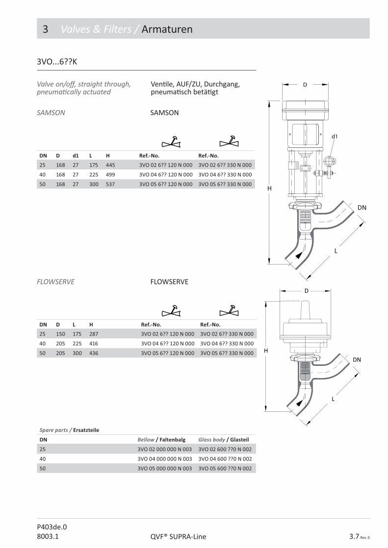
3 Valves & Filters / Armaturen
3.7-Rev. 0QVF® SUPRA-LineP403de.08003.1
SAMSON SAMSON
3VO...6??K
Valve on/o� , straight through, pneuma� cally actuated
Ven� le, AUF/ZU, Durchgang, pneuma� sch betä� gt
FLOWSERVE FLOWSERVED
DN D d1 L H Ref.-No. Ref.-No.
25 168 27 175 445 3VO 02 6?? 120 N 000 3VO 02 6?? 330 N 000
40 168 27 225 499 3VO 04 6?? 120 N 000 3VO 04 6?? 330 N 000
50 168 27 300 537 3VO 05 6?? 120 N 000 3VO 05 6?? 330 N 000
DN D L H Ref.-No. Ref.-No.
25 150 175 287 3VO 02 6?? 120 N 000 3VO 02 6?? 330 N 000
40 205 225 416 3VO 04 6?? 120 N 000 3VO 04 6?? 330 N 000
50 205 300 436 3VO 05 6?? 120 N 000 3VO 05 6?? 330 N 000
Spare parts / Ersatzteile
DN Bellow / Faltenbalg Glass body / Glasteil
25 3VO 02 000 000 N 003 3VO 02 600 ??0 N 002
40 3VO 04 000 000 N 003 3VO 04 600 ??0 N 002
50 3VO 05 000 000 N 003 3VO 05 600 ??0 N 002
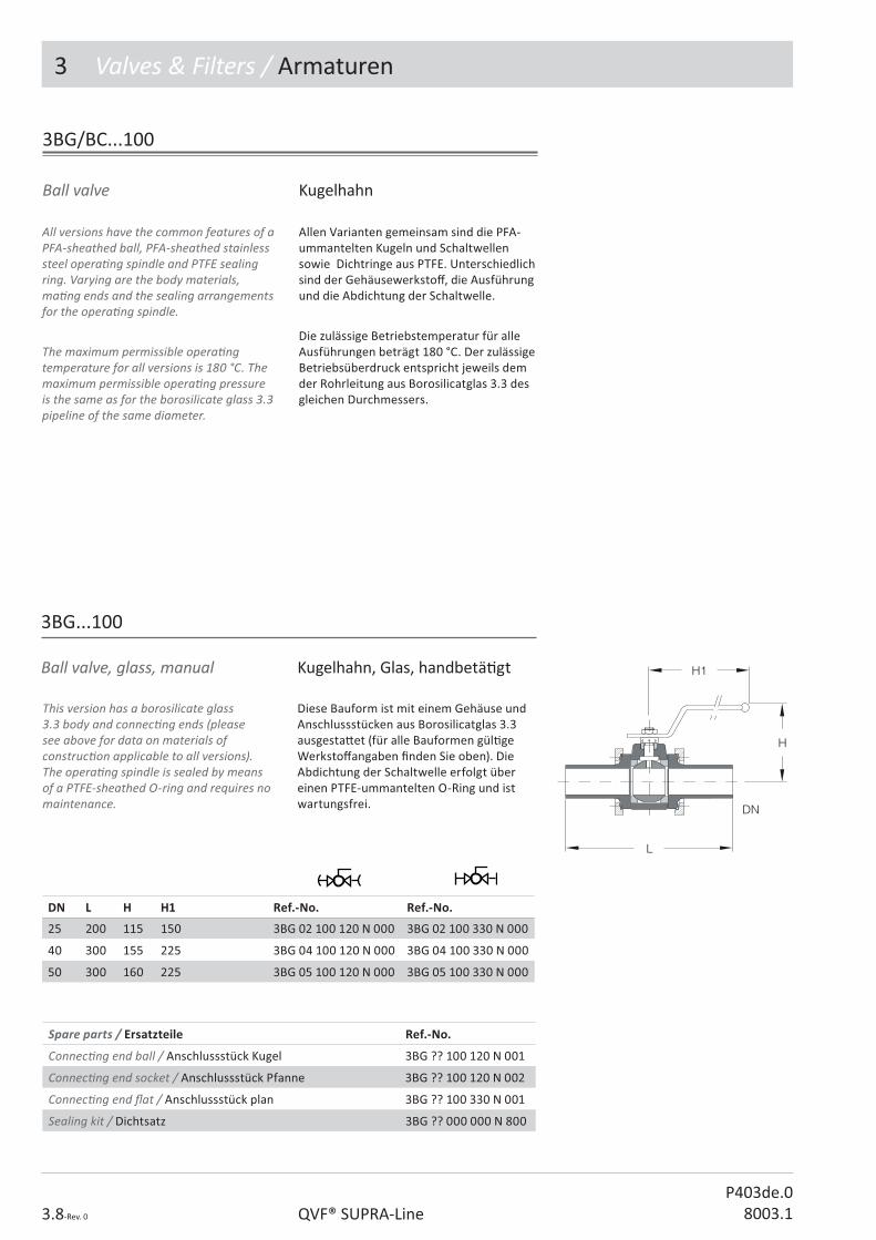
3 Valves & Filters / Armaturen
P403de.08003.1QVF® SUPRA-Line3.8-Rev. 0
Allen Varianten gemeinsam sind die PFA-ummantelten Kugeln und Schaltwellen sowie Dichtringe aus PTFE. Unterschiedlich sind der Gehäusewerksto� , die Ausführung und die Abdichtung der Schaltwelle.
Die zulässige Betriebstemperatur für alle Ausführungen beträgt 180 °C. Der zulässige Betriebsüberdruck entspricht jeweils dem der Rohrleitung aus Borosilicatglas 3.3 des gleichen Durchmessers.
All versions have the common features of a PFA-sheathed ball, PFA-sheathed stainless steel opera� ng spindle and PTFE sealing ring. Varying are the body materials, ma� ng ends and the sealing arrangements for the opera� ng spindle.
The maximum permissible opera� ng temperature for all versions is 180 °C. The maximum permissible opera� ng pressure is the same as for the borosilicate glass 3.3 pipeline of the same diameter.
KugelhahnBall valve
3BG/BC...100
DN L H H1 Ref.-No. Ref.-No.
25 200 115 150 3BG 02 100 120 N 000 3BG 02 100 330 N 000
40 300 155 225 3BG 04 100 120 N 000 3BG 04 100 330 N 000
50 300 160 225 3BG 05 100 120 N 000 3BG 05 100 330 N 000
Kugelhahn, Glas, handbetä� gtBall valve, glass, manual
3BG...100
This version has a borosilicate glass 3.3 body and connec� ng ends (please see above for data on materials of construc� on applicable to all versions). The opera� ng spindle is sealed by means of a PTFE-sheathed O-ring and requires no maintenance.
Diese Bauform ist mit einem Gehäuse und Anschlussstücken aus Borosilicatglas 3.3 ausgesta� et (für alle Bauformen gül� ge Werksto� angaben � nden Sie oben). Die Abdichtung der Schaltwelle erfolgt über einen PTFE-ummantelten O-Ring und ist wartungsfrei.
Spare parts / Ersatzteile Ref.-No.
Connec� ng end ball / Anschlussstück Kugel 3BG ?? 100 120 N 001
Connec� ng end socket / Anschlussstück Pfanne 3BG ?? 100 120 N 002
Connec� ng end � at / Anschlussstück plan 3BG ?? 100 330 N 001
Sealing kit / Dichtsatz 3BG ?? 000 000 N 800

3 Valves & Filters / Armaturen
3.9-Rev. 0QVF® SUPRA-LineP403de.08003.1
A feature of these compact ball valves with body and connec� ng � anges made of spheroidal graphite cast iron/PFA is their short overall length. They are ideal for installa� on in borosilicate glass 3.3 pipelines between components with � at ends. The opera� ng spindle is sealed by means of a self-adjus� ng, maintenance-free stu� ng box.
Diese Kompaktkugelhähne mit Gehäuse und Anschluss� anschen aus Kugelgra� t-guss/PFA zeichnen sich durch eine kurze Bauform aus. Sie eignen sich für den Einbau in Rohrleitungen aus Borosilicatglas 3.3 in Plan-Ausführung.
Die Abdichtung der Schaltwelle erfolgt über eine selbstnachstellende, wartungs-freie Stop$ uchse.
Kugelhahn, Kompakt, hand-betä� gt
Ball valve, compact, manual
3BC...100
DN L H H1 E K x n x d Ref.-No.
25 80 115 150 15 85 x 4 x M8 3BC 02 100 000 N 000
40 100 155 225 16 110 x 4 x M8 3BC 04 100 000 N 000
50 125 160 225 23 125 x 4 x M8 3BC 05 100 000 N 000
Spare parts / Ersatzteile Ref.-No.
Connec� ng end / Anschlussstück 3BC ?? 100 000 N 001
Sealing kit / Dichtsatz 3BC ?? 000 000 N 800
The connec� ng kit consists of a stainless steel � ange ring with insert, silicone shim, bolts and spring elements to connect one end of the ball valve.
Der Anbausatz besteht aus Edelstahl-flanschringen mit Beilagen, Unterlagen, Schrauben und Federelementen zum An-schluss einer Seite des Kugelhahnes.
Anbausatz, Kugelhahn, KompaktConnec� ng kit, ball valve, compact
Ref.-No.
Connec� ng kit / Anbausatz 9AS ?? 000 300 E 000

3 Valves & Filters / Armaturen
P403de.08003.1QVF® SUPRA-Line3.10-Rev. 0
All the manually operated ball valves described above can be supplied with NORBRO single-ac� on actuators. Their spring return ac� on can be set at will as a safety feature to either »spring to open« or »spring to close«.Technical data and installa� on dimensions of these ball valves are the same as for the manually operated version.Compressed air is required at 5.5 bar g for single-ac� on actuators with the full number of springs.To avoid the sudden build-up of high surface pressure between the ball and opera� ng spindle at the start of the opening or shu� ng ac� on, we recommend the incorpora� on of air � ow controls in the supply line to the actuator.
Alle vorstehend beschriebenen, handbe-tä� gten Kugelhähne sind standardmäßig auch mit einfachwirkenden Antrieben der Firma NORBRO lieferbar. Deren Federrück-stellung bietet den Vorteil der frei wählbaren Sicherheitsstellung »Feder ö� net« bzw. »Feder schließt«.
Die technischen Daten und Einbaumaße der Kugelhähne entsprechen Handarmatur.
Der erforderliche Zulu� druck beträgt 5,5 bar für den einfachwirkenden Antrieb mit voller Federzahl.
Um den plötzlichen Au$ au hoher Flächen-pressungen zwischen Kugel und Schaltwelle zu Beginn des Ö� nungs- oder Schließvor-ganges zu vermeiden, empfehlen wir den Einbau von Lu� drosseln in die Zulu� leitung zum Drehantrieb.
Kugelhahn, pneuma� sch betä� gtBall valve, pneuma� cally actuated
3BG/BC...2??K
Fail-save version / Sicherheitsstellung Code
Spring to open / Feder ö� net 5
Spring to close / Feder schließt 6
Op� ons for pneum. drive / Op� onen für pneum. Antrieb
ohne / without 0
2 x Induc� ve limit switch / 2x Induk� ve Endschalter II 2 G Ex ia IIC T6 1
Design key Ausführungsschlüssel

3 Valves & Filters / Armaturen
3.11-Rev. 0QVF® SUPRA-LineP403de.08003.1
Ball valve, pneuma� cally actuated, compact
Kugelhahn, pneuma� sch betä� gt, Kompakt
3BC...2??
DN L H H1 Ref.-No. Ref.-No.
25 200 182 155 3BG 02 2?? 120 N 000 3BG 02 2?? 330 N 000
40 300 240 195 3BG 04 2?? 120 N 000 3BG 04 2?? 330 N 000
50 300 244 195 3BG 05 2?? 120 N 000 3BG 05 2?? 330 N 000
DN L H H1 E K x n x d Ref.-No.
25 80 208 155 15 85x4xM8 3BC 02 2?? 000 N 000
40 100 255 195 16 110x4xM8 3BC 04 2?? 000 N 000
50 125 259 195 23 125x4xM8 3BC 05 2?? 000 N 000
Kugelhahn, Glas, pneuma� sch betä� gt
Ball valve, glass, pneuma� cally actuated
3BG...2??
Spare parts / Ersatzteile Ref.-No.
Connec� ng end ball / Anschlussstück Kugel 3BG ?? 100 120 N 001
Connec� ng end socket / Anschlussstück Pfanne 3BG ?? 100 120 N 002
Connec� ng end � at / Anschlussstück plan 3BG ?? 100 330 N 001
Sealing kit / Dichtsatz 3BG ?? 000 000 N 800
Spare parts / Ersatzteile Ref.-No.
Connec� ng end / Anschlussstück 3BC ?? 100 000 N 001
Sealing kit / Dichtsatz 3BC ?? 000 000 N 800
The connec� ng kit consists of a stainless steel � ange ring with insert, silicone shim, bolts and spring elements to connect one end of the ball valve.
Der Anbausatz besteht aus Edelstahl-� anschringen mit Beilagen, Unterlagen, Schrauben und Federelementen zum Anschluss einer Seite des Kugelhahnes.
Anbausatz, Kugelhahn, pneuma� sch betä� gt, Kompakt
Connec� ng kit, ball valve, pneuma� cally actuated, compact
Ref.-No.
Connec� ng kit / Anbausatz 9AS ?? 000 300 E 000

3 Valves & Filters / Armaturen
P403de.08003.1QVF® SUPRA-Line3.12-Rev. 0
These valves, which close with a gas-� ght seal, complement our ball valve range for larger bores. In reac� on units they can be used to separate the dis� lla� on overhead gear from the reac� on vessel when it is intended to operate the la� er for periods at higher pressure.These bu� er� y valves comprise essen� ally a PFA-sheathed stainless steel disk/opera� ng spindle unit, a two-part PFA / spheroidal graphite cast iron body, a maintenance-free, self-adjus� ng opera� ng spindle seal. The body is epoxy resin coated.Bu� er� y valves of nominal size DN 50 are supplied as standard with a hand lever with � xed intermediate se� ngs. Larger valves are supplied with a geared handwheel. All sizes can be supplied with pneuma� c actuators if required.These bu� er� y valves can also be used for connec� ons to glass lined steel nozzles. The corresponding sets of adaptors have to be ordered separately (see sec� on couplings).Permissible opera� ng condi� ons: -40°C to +200°C190°C at -0.5 ÷ +4 bar g and 120°C at -1 ÷ +4 bar g.
Diese gasdicht abschließenden Armaturen ergänzen unser Kugelhahn-Programm im Bereich größerer Nennweiten.
In Reak� onsanlagen können sie zur Trennung von Des� lla� onsaufsatz und Reak� onsbe-hälter eingesetzt werden, wenn die Absicht besteht, letzteren zeitweise bei höherem Druck zu betreiben.
Die Klappen bestehen im Wesentlichen aus der PFA-ummantelten Einheit Scheibe/Schaltwelle aus Edelstahl, einem zweiteiligen Gehäuse aus Kugelgra� tguss/PFA und der wartungsfreien, selbstnachstellenden Schaltwellenabdichtung. Die Gehäuse sind epoxidharzlackiert.
Standardmäßig werden die Klappen mit einem Handhebel (nur Nennweite DN 50) für feste Zwischenstellungen (Raster) bzw. einem Schneckengetriebe mit Handrad, auf Wunsch jedoch auch mit pneuma� schem Drehantrieb geliefert.
Die Klappen eignen sich für einen Anschluss an Stutzen aus Glas bzw. emailliertem Stahl. Die jeweils erforderlichen Anbausätze sind separat zu bestellen (siehe Kapitel Verbindungen).
Zulässige Betriebsbedingungen:
-40°C bis +200°C190°C bei -0,5 ÷ +4 bar und 120°C bei -1 ÷ +4 bar.
KlappeFlap, bu� er� y type
3FB
DN L L1 H H1 H2 H3 Ref.-No.
50 43 4 175 300 - 66 3FB 05 000 000 N 000
80 46 18 262 120 181 93 3FB 08 000 000 N 000
100 52 25 277 120 181 106 3FB 10 000 000 N 000
150 56 48 314 120 181 135 3FB 15 000 000 N 000
200 60 71 334 120 181 165 3FB 20 000 000 N 000
300 78 112 462 195 206 230 3FB 30 000 000 N 000
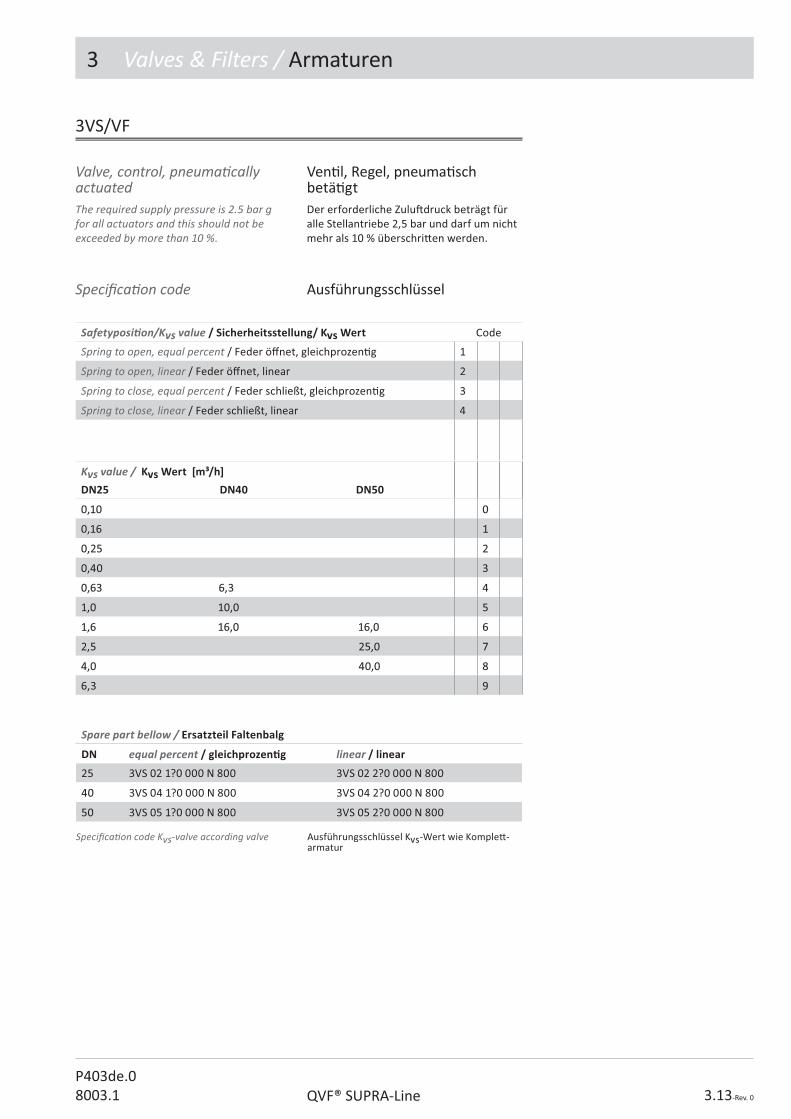
3 Valves & Filters / Armaturen
3.13-Rev. 0QVF® SUPRA-LineP403de.08003.1
The required supply pressure is 2.5 bar g for all actuators and this should not be exceeded by more than 10 %.
Der erforderliche Zulu� druck beträgt für alle Stellantriebe 2,5 bar und darf um nicht mehr als 10 % überschri� en werden.
3VS/VF
Ven� l, Regel, pneuma� sch betä� gt
Valve, control, pneuma� cally actuated
Safetyposi� on/Kvs value / Sicherheitsstellung/ Kvs Wert Code
Spring to open, equal percent / Feder ö� net, gleichprozen� g 1
Spring to open, linear / Feder ö� net, linear 2
Spring to close, equal percent / Feder schließt, gleichprozen� g 3
Spring to close, linear / Feder schließt, linear 4
Kvs value / Kvs Wert [m³/h]DN25 DN40 DN50
0,10 0,10 00
0,16 0,16 11
0,25 0,25 22
0,40 0,40 33
0,63 6,3 0,63 6,3 44
1,0 10,0 1,0 10,0 55
1,6 16,0 16,01,6 16,0 16,0 66
2,5 25,02,5 25,0 77
4,0 40,04,0 40,0 88
6,36,3 99
Speci� ca� on code Ausführungsschlüssel
Spare part bellow / Ersatzteil Faltenbalg
DN equal percent / gleichprozen� g linear / linear
25 3VS 02 1?0 000 N 800 3VS 02 2?0 000 N 800
4040 3VS 04 1?0 000 N 800 3VS 04 2?0 000 N 800
5050 3VS 05 1?0 000 N 800 3VS 05 2?0 000 N 800
Speci� ca� on code Kvs-valve according valve Ausführungsschlüssel Kvs-Wert wie Komple� -armatur

3 Valves & Filters / Armaturen
P403de.08003.1QVF® SUPRA-Line3.14-Rev. 0
Ven� l, Regel, SAMSON-Stell-antrieb
Valve, control, SAMSON actuator
3VS
DN D d1 L L1 H Ref.-No. Ref.-No.
25 168 27 100 164 394 3VS 02 ??? 120 N 000 3VS 02 ??? 330 N 000
40 168 27 150 180 534 3VS 04 ??? 120 N 000 3VS 04 ??? 330 N 000
50 168 27 150 190 544 3VS 05 ??? 120 N 000 3VS 05 ??? 330 N 000
Design key / Ausführungsschlüssel Code
HART-Posi� oner / HART-Stellungsregler 0
HART+ 1x induc� ve switch / HART + 1x Endschalter 1
Control valves with Samson actuator are delivered with a HART-posi� oner. One induc� ve switch is available as an op� on.
Regelven� le mit einem Samson-Antrieb werden standardmäßig mit einem HART-Stellungsregler geliefert. Als Op� on ist ein Endschalter wählbar.

3 Valves & Filters / Armaturen
3.15-Rev. 0QVF® SUPRA-LineP403de.08003.1
Ven� l, Regel, FLOWSERVE-Stellantrieb
Valve, control, FLOWSERVE actuator
3VF
DN D d1 L L1 H Ref.-No. Ref.-No.
25 150 27 100 164 445 3VF 02 ??? 120 N 000 3VF 02 ??? 330 N 000
40 205 27 150 180 584 3VF 04 ??? 120 N 000 3VF 04 ??? 330 N 000
50 205 27 150 190 594 3VF 05 ??? 120 N 000 3VF 05 ??? 330 N 000
Design key / Ausführungsschlüssel Code
IP-Posi� oner without op� ons / IP-Stellungsregler o. Op� onen II 2 G Ex ia II C T6 0
IP+ 2x induc� ve switch / IP + 2x Endschalter (H= H+80mm) II 2 G Ex ia II C T6 1
Control valves with FLOWSERVE actuator are delivered with an IP-posi� oner. Two induc� ve switches are available as an op� on.
Regelven� le mit einem FLOWSERVE-Antrieb werden standardmäßig mit einem IP-Stellungsregler geliefert. Als Op� on sind zwei Endschalter wählbar.

3 Valves & Filters / Armaturen
P403de.08003.1QVF® SUPRA-Line3.16-Rev. 0
These safety valves are o� cially tested and approved for gases and vapours. They are valves with a proven glass/PTFE seat/plug combina� on and are used to protect plant and equipment. Before delivery, each valve is durably marked with the component reference issued by the no� � ed body. When ordering, please indicate the catalogue reference and the required blow-o� pressure in the design key.The se� ng pressure can only be changed by specialist personnel (e.g. by De Dietrich Process Systems). The valve must then be resealed and the model label altered.To ensure that they func� on properly, pressure relief valves must always be installed ver� cally.
Diese für Gase und Dämpfe zugelassenen Sicherheitsven� le mit der bewährten Sitz-/ Kegel-Kombina� on aus Glas/PTFE dienen der Absicherung von Apparaten und Anlagen.
Vor Auslieferung wird jedes Ven� l dauer-ha� mit dem vom TÜV erteilten Bauteil-kennzeichen versehen.
Bei Au� ragserteilung ist neben der Bestell-Nr. der gewünschte Einstellüberdruck im Aus-führungsschlüssel anzugeben.
Eine Änderung des Einstellüberdruckes ist nur durch einen Sachkundigen (z.B. durch De Dietrich Process Systems) möglich. Das Ven� l muss anschließend wieder verplombt und das Typenschild geändert werden.
Zwecks einwandfreier Funk� on müssen Sicherheitsven� le immer senkrecht stehend eingebaut werden.
Ven� l, SicherheitValve, relief
3VR
DN DN1 DN2 L L1 H Ref.-No. Ref.-No.
25 50 80 150 125 325 3VR 02 ??? 110 K 000 3VR 02 ??? 330 K 000
50 80 100 150 150 395 3VR 05 ??? 110 K 000 3VR 05 ??? 330 K 000
100 150 150 200 225 485 3VR 10 ??? 110 K 000 3VR 10 ??? 330 K 000
DN do Ao (mm2) �wp (bar)
25 25 490 0,44 0,26-1,51
50 50 1960 0,10 0,08-0,25
50 50 1960 0,19 0,18-1,39
100 100 7850 0,17 0,07-1,18
Technical data Technische Daten
Indicate blow-o� pressure without dot e.g. 0.53 bar g = 053
Angabe des Einstellüberdrucks ohne Komma z.B. 0,53 bar = 053

3 Valves & Filters / Armaturen
3.17-Rev. 0QVF® SUPRA-LineP403de.08003.1
These loading valves are used to maintain a constant pressure and are recommended for use a� er dosing pumps. They can be used to deliver liquids into or out of a vacuum, for example. Unlike manually operated types, this valve has a spring which can be adjusted. Thus values between 0.5 bar g and 3 bar g may be set with a tolerance range of ± 0.3 bar. Please specify pressure se� ng on the order.
Permissible working temperature TS: 0 to 150 °CPermissible opera� ng pressure PS:4 bar g
Loading valves should not be used as pressure relief valves.
Sie dienen zur Einstellung eines konstanten Gegendruckes und werden vorzugsweise hinter Dosierpumpen eingesetzt.
So ermöglichen sie z.B. die Förderung von Flüssigkeiten in ein oder aus einem Vakuum.
An die Stelle der bei anderen Ven� len üblichen Handbetä� gung tri� eine Feder, deren Vorspannung verändert werden kann.
Dadurch sind Werte zwischen 0,5 bar und 3 bar mit einer Toleranz von ± 0,3 bar einstellbar. Bi� e bei Bestellung den ge-wünschten Einstellüberdruck angeben.
Zulässige Betriebstemperatur TS:0 bis 150 °C
Zulässiger Betriebsüberdruck PS:4 bar
Druckhalte-Eckven� le dürfen nicht als Sicherheitsven� le eingesetzt werden.
Ven� l, DruckhalteValve, loading
3VL
DN L H Ref.-No. Ref.-No.
15 50 165 3VL 01 ??? 120 K 000 3VL 01 ??? 330 K 000
25 100 159 3VL 02 ??? 120 K 000 3VL 02 ??? 330 K 000
40 150 194 3VL 04 ??? 120 K 000 3VL 04 ??? 330 K 000
Indicate blow-o� pressure without dot e.g. 0.8 bar g = 080
Angabe des Einstellüberdrucks ohne Komma z.B. 0,8 bar = 080

3 Valves & Filters / Armaturen
P403de.08003.1QVF® SUPRA-Line3.18-Rev. 0
The PTFE seat, ball and retaining plate provide excellent corrosion resistance.Ball-type non-return valves are not suitable for use as a long-term shut-o� func� on.
Sitz, Kugel und Fangpla� e aus PTFE gewähr-leisten eine ausgezeichnete Korrosionsbe-ständigkeit.
Kugelrückschlagventile können keine bleibende Absperrfunk� on übernehmen.
Ven� l, Rückschlag, Kugel Valve, non-return, ball valve
3NB
DN DN1 d1 L Ref.-No. Ref.-No.
25 50 23 225 3NB 02 ??? 120 N 000 3NB 02 ??? 330 N 000
40 80 48 325 3NB 04 ??? 120 N 000 3NB 04 ??? 330 N 000
50 80 48 325 3NB 05 ??? 120 N 000 3NB 05 ??? 330 N 000
Op� ons / Op� onen: Code
Full ball / Vollkugel 100
Hollow ball / Hohlkugel 200
Spare parts / Ersatzteile Ref.-No.
Retaining cage / Fangkorb DN25 3NB 02 000 000 N 800
Retaining cage / Fangkorb DN40/50 3NB 04 000 000 N 800
Ball / Kugel DN25 3NB 02 ??? 000 N 104
Ball / Kugel DN40/50 3NB 04 ??? 000 N 104

3 Valves & Filters / Armaturen
3.19-Rev. 0QVF® SUPRA-LineP403de.08003.1
This version provides a large free cross-sec� on even in small nominal sizes and consequently ensures low pressure drop. It is suitable for liquids and installa� on in horizontal and ver� cal pipelines.The PTFE � aps are mounted on tantalum hinges which must be located at the top when installed in horizontal lines.Flap-type non-return valves are not suitable to provide a long-term shut-o� func� on.
Diese Ausführung gewährleistet auch bei kleinen Nennweiten einen großen freien Querschni� und somit einen niedrigen Druckverlust. Sie eignet sich für Flüssig-keiten und den Einbau in horizontalen und ver� kalen Rohrleitungen.
Die PTFE-Klappen sind mit Tantal-Scharnieren befes� gt, die sich bei waagerechtem Ein-bau oben be� nden müssen.
Rückschlagklappen können keine bleibende Absperrfunk� on übernehmen.
Ven� l, Rückschlag, Klappe, GlasValve, non-return, � ap, glass
3NF...100/200
DN DN1 L Ref.-No. Ref.-No.
25 50 225 3NF 02 100 120 N 000 3NF 02 100 330 N 000
40 80 275 3NF 04 100 120 N 000 3NF 04 100 330 N 000
50 100 325 3NF 05 100 120 N 000 3NF 05 100 330 N 000
ver� cal
DN DN1 L E Ref.-No. Ref.-No.
25 50 225 12 3NF 02 200 120 N 000 3NF 02 200 330 N 000
40 80 275 18 3NF 04 200 120 N 000 3NF 04 200 330 N 000
50 100 325 27 3NF 05 200 120 N 000 3NF 05 200 330 N 000
horizontal
ver� kal
horizontal

3 Valves & Filters / Armaturen
P403de.08003.1QVF® SUPRA-Line3.20-Rev. 0
These PTFE � ap-type non-return valves can be � � ed in horizontal or ver� cal pipelines with � at � anges. No addi� onal gaskets are required.The PTFE � aps are mounted on tantalum hinges which must be located at the top when installed in horizontal lines.The maximum permissible opera� ng temperature for these � ap-type non-return valves is 130 °C. The permissible opera� ng pressure is the same as for pipeline components of the same nominal size.Flap-type non-return valves are not suitable to provide a long-term shut-o� func� on.
Diese PTFE-Rückschlagklappen können direkt in eine waagerechte oder senkrechte Rohrleitung mit Plan� anschen eingebaut werden. Zusätzliche Dichtungen werden nicht benö� gt.
Die PTFE-Klappen sind mit Tantal-Scharnieren befes� gt, die sich bei waagerechtem Ein-bau oben be� nden müssen.
Die maximal zulässige Betriebstemperatur dieser Klappen beträgt 130 °C. Der zulässige Betriebsüberdruck entspricht dem der Rohrleitungsbauteile gleicher Nennweite.
Rückschlagklappen können keine bleibende Absperrfunk� on übernehmen.
Ven� l, Rückschlag, Klappe, PTFEValve, non-return, � ap, PTFE
3NF
DN d L Ref.-No.
50 30 24 3NF 05 000 330 D 000
80 55 24 3NF 08 000 330 D 000
100 82 24 3NF 10 000 330 D 000
150 125 25 3NF 15 000 330 D 000
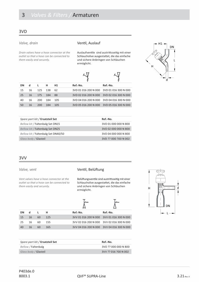
3 Valves & Filters / Armaturen
3.21-Rev. 0QVF® SUPRA-LineP403de.08003.1
Drain valves have a hose connector at the outlet so that a hose can be connected to them easily and securely.
Auslaufven� le sind austri� ssei� g mit einer Schlaucholive ausgesta� et, die das einfache und sichere Anbringen von Schläuchen ermöglicht.
Ven� l, AuslaufValve, drain
3VD
DN d L H H1 Ref.-No. Ref.-No.
15 16 125 138 62 3VD 01 016 200 N 000 3VD 01 016 300 N 000
25 16 175 184 88 3VD 02 016 200 N 000 3VD 02 016 300 N 000
40 16 200 184 105 3VD 04 016 200 N 000 3VD 04 016 300 N 000
50 16 200 184 105 3VD 05 016 200 N 000 3VD 05 016 300 N 000
Ven� l, Belü� ungValve, vent
3VV
Vent valves have a hose connector at the outlet so that a hose can be connected to them easily and securely.
Belü� ungsven� le sind austri� ssei� g mit einer Schlaucholive ausgesta� et, die das einfache und sichere Anbringen von Schläuchen ermöglicht.
DN d L H Ref.-No. Ref.-No.
15 16 60 125 3VV 01 016 200 N 000 3VV 01 016 300 N 000
25 16 60 155 3VV 02 016 200 N 000 3VV 02 016 300 N 000
40 16 60 165 3VV 04 016 200 N 000 3VV 04 016 300 N 000
Spare part kit / Ersatzteil Set Ref.-No.
Bellow kit / Faltenbalg Set DN15 3VO 01 000 000 N 800
Bellow kit / Faltenbalg Set DN25 3VO 02 000 000 N 800
Bellow kit / Faltenbalg Set DN40/50 3VO 04 000 000 N 800
Glass body / Glasteil 3VD ?? 000 ?00 N 002
Spare part kit / Ersatzteil Set Ref.-No.
Bellow / Faltenbalg 3VO ?? 000 000 N 800
Glass body / Glasteil 3VV ?? 016 ?00 N 002

3 Valves & Filters / Armaturen
P403de.08003.1QVF® SUPRA-Line3.22-Rev. 0
These valves are recommended for adjus� ng the interface in separators, azeotropic column heads or similar units. Level adjustment is in� nitely variable by means of a PTFE tube � � ed with sealing lips and can be moved up and down inside a precision bore glass tube.
Sie werden vorzugsweise zum Einstellen von Trennschichten in Abscheidern, Azeotrop-Kolonnenköpfen oder ähnlichen Apparaten verwendet. Die Höhenverstellung erfolgt stufenlos mi� els eines PTFE-Rohres, das mit Dichtlippen in einem Präzisionsrohr geführt wird.
Ven� l, Überlauf, verstellbarValve, adjustable, over� ow
3VA
DN DN1 d L Ref.-No. Ref.-No.
25 15 25 100 3VA 02 000 123 N 000 3VA 02 000 333 N 000
40 15 25 150 3VA 04 000 123 N 000 3VA 04 000 333 N 000
50 15 35 150 3VA 05 000 123 N 000 3VA 05 000 333 N 000
80 15 60 200 3VA 08 000 123 N 000 3VA 08 000 333 N 000
DN L1 L2 L3 L4 H Maximum � ow rate (l/h)Maximaler Durchsatz (l/h)
25 165 50 255 78 340 600
40 265 90 435 78 470 900
50 270 90 435 75 470 1600
80 330 120 555 100 580 3200
Technische DatenTechnical data
Spare parts / Ersatzteile Ref.-No.
Bellow / Faltenbalg 3VA ?? 000 000 N 002

3 Valves & Filters / Armaturen
3.23-Rev. 0QVF® SUPRA-LineP403de.08003.1
With normal three way valves it is possible to close both outlets at the same � me by mistake. The three way valve provides a safe solu� on to this problem since the design ensures that free � ow through the valve is never impeded.
Bei herkömmlichen Dreiwegeven� len kann eine Fehlbedienung dazu führen, dass beide Abgänge gleichzei� g verschlossen sind. Dieses Problem wird durch die Drei-wegearmatur sicher vermieden, da ein Durchgang konstruktiv bedingt immer geöffnet ist.
Ven� l, DreiwegeValve, three way
3VT
DN L L1 H Ref.-No. Ref.-No.
25 100 160 232 3VT 02 000 122 N 000 3VT 02 000 333 N 000
40 150 220 270 3VT 04 000 122 N 000 3VT 04 000 333 N 000
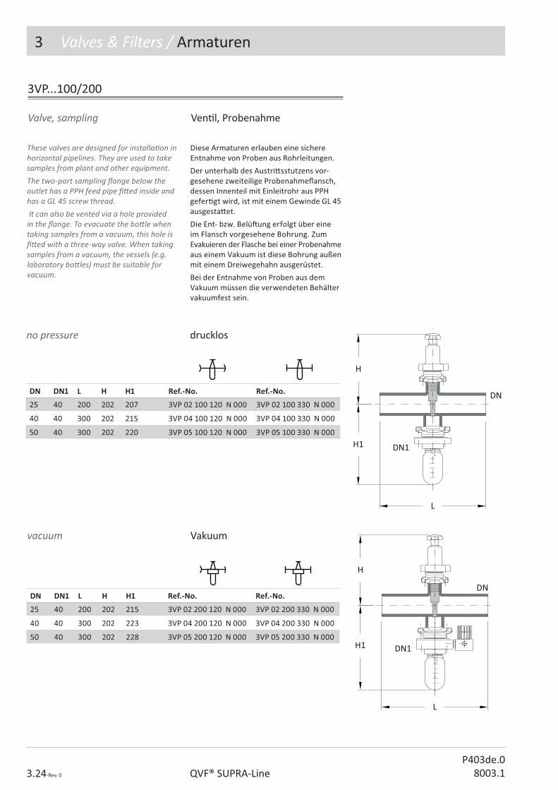
P403de.08003.1QVF® SUPRA-Line3.24-Rev. 0
3 Valves & Filters / Armaturen
These valves are designed for installa� on in horizontal pipelines. They are used to take samples from plant and other equipment. The two-part sampling � ange below the outlet has a PPH feed pipe � � ed inside and has a GL 45 screw thread. It can also be vented via a hole provided in the � ange. To evacuate the bo� le when taking samples from a vacuum, this hole is � � ed with a three-way valve. When taking samples from a vacuum, the vessels (e.g. laboratory bo� les) must be suitable for vacuum.
Diese Armaturen erlauben eine sichere Entnahme von Proben aus Rohrleitungen.
Der unterhalb des Austri� sstutzens vor-gesehene zweiteilige Probenahme� ansch, dessen Innenteil mit Einleitrohr aus PPH gefer� gt wird, ist mit einem Gewinde GL 45 ausgesta� et.
Die Ent- bzw. Belü� ung erfolgt über eineim Flansch vorgesehene Bohrung. Zum Evakuieren der Flasche bei einer Probenahme aus einem Vakuum ist diese Bohrung außen mit einem Dreiwegehahn ausgerüstet.
Bei der Entnahme von Proben aus dem Vakuum müssen die verwendeten Behälter vakuumfest sein.
Ven� l, ProbenahmeValve, sampling
3VP...100/200
DN DN1 L H H1 Ref.-No. Ref.-No.
25 40 200 202 207 3VP 02 100 120 N 000 3VP 02 100 330 N 000
40 40 300 202 215 3VP 04 100 120 N 000 3VP 04 100 330 N 000
50 40 300 202 220 3VP 05 100 120 N 000 3VP 05 100 330 N 000
DN DN1 L H H1 Ref.-No. Ref.-No.
25 40 200 202 215 3VP 02 200 120 N 000 3VP 02 200 330 N 000
40 40 300 202 223 3VP 04 200 120 N 000 3VP 04 200 330 N 000
50 40 300 202 228 3VP 05 200 120 N 000 3VP 05 200 330 N 000
Vakuumvacuum
drucklosno pressure

3 Valves & Filters / Armaturen
3.25-Rev. 0QVF® SUPRA-LineP403de.08003.1
Wenn feinste Verunreinigungen aus Flüssigkeits- oder Gasströmen en# ernt werden müssen, empfehlen wir für den Einbau in Glasleitungen unsere bewährten Rohrleitungs� lter mit Kerzen aus Werk-sto� Carbo. Sie werden in Körnung 30 mit einer mi� leren Porenweite von 40 ;m geliefert.
Der Verschmutzungsgrad ist, sofern es das Produkt zulässt, durch das Gehäuse aus Borosilicatglas 3.3 stets gut zu beobachten. Ein einfaches Reinigen oder Auswechseln der Filterkerzen wird durch die Spannvor-richtung ermöglicht.
Filter, RohrleitungFilter, pipeline
3FP
DN DN1 DN2 L L1 L2 H Ref.-No. Ref.-No.
25 15 80 100 85 400 345 3FP 02 000 120 N 000 3FP 02 000 330 N 000
40 25 100 150 96 652 550 3FP 04 000 120 N 000 3FP 04 000 330 N 000
50 25 100 150 96 652 550 3FP 05 000 120 N 000 3FP 05 000 330 N 000
Our proven pipeline � lters with ceramic elements are recommended for the removal of very � ne impuri� es from liquid or gas streams in glass pipeline systems. They are supplied in grain size 30 with an average pore diameter of 40 �m. The degree of contamina� on can be observed clearly at all � mes through the borosilicate glass 3.3 body provided the product permits it. The assembly is designed for easy cleaning or replacement of the � lter element.
Spare parts / Ersatzteile Ref.-No.
Ceramic element / Filtereinsatz DN 25 3FP 02 000 000 N 008
Ceramic element / Filtereinsatz DN 40/50 3FP 04 000 000 N 008

3 Valves & Filters / Armaturen
P403de.08003.1QVF® SUPRA-Line3.26-Rev. 0
Schrägsitz� lter mit PTFE-Einsatz eignen sich für den Einbau in Rohrleitungen.
Schmutzfänger sind als Grob� lter mit 2 mm Bohrungsdurchmesser im PTFE-Zylinder lieferbar. Beim Fein� lter wird über den Stützzylinder ein ETFE-Filterstrumpf mit Maschenweiten von 100, 300 oder 500 ;m gezogen. Der Druckverlust von Wasser bei einer Strömungsgeschwindigkeit von 1 m/s im Rohr beträgt ca. 50 mbar.
Filter, SchmutzfängerFilter, trap
3FT
Filter, grobFilter, coarse
Filter, feinFilter, � ne
DN DN1 L H H1 Ref.-No. Ref.-No.
25 40 175 170 160 3FT 02 000 120 N 000 3FT 02 000 330 N 000
40 50 225 170 160 3FT 04 000 120 N 000 3FT 04 000 330 N 000
50 80 300 170 160 3FT 05 000 120 N 000 3FT 05 000 330 N 000
DN DN1 L H H1 Ref.-No. Ref.-No.
25 40 175 170 160 3FT 02 ??? 120 N 000 3FT 02 ??? 330 N 000
40 50 225 170 160 3FT 04 ??? 120 N 000 3FT 04 ??? 330 N 000
50 80 300 170 160 3FT 05 ??? 120 N 000 3FT 05 ??? 330 N 000
These angled � lters with PTFE inserts are designed for pipeline systems.
Dirt traps can be supplied as coarse � lters, with 2 mm diameter holes in the PTFE cylinder. In case of � ne � lters an ETFE � lter sleeve with a mesh size of 100, 300 or 500 �m is � � ed over the support cylinder. The pressure drop of water is about 50 mbar at a velocity of 1 m/s in the pipeline.
3FT...000
3FT...100/300/500
Indicate of mesh size e.g. 100 �m = 100 Angabe zu Maschenweite z.B. 100 �m = 100
Spare parts / Ersatzteile Ref.-No.
Filter sleeve / Filterstrumpf 3FT ?? ??? 000 N 004

P404e.08003.1
������������� �������
2. Pipeline Components
3. Valves and Filters
4. VESSELS
5. Heat Exchangers
6. Column Components
������������
8. Measurement and Control
9. Couplings
10. Structures and Supports
The Component System
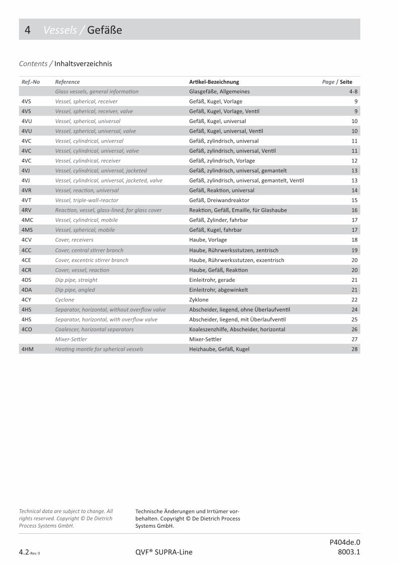
4 Vessels / Gefäße
4.2-Rev. 0 QVF® SUPRA-LineP404de.0
8003.1
Ref.-No Reference Ar� kel-Bezeichnung Page / Seite
Glass vessels, general informa� on Glasgefäße, Allgemeines 4-8
4VS Vessel, spherical, receiver Gefäß, Kugel, Vorlage 9
4VS Vessel, spherical, receiver, valve Gefäß, Kugel, Vorlage, Ven� l 9
4VU Vessel, spherical, universal Gefäß, Kugel, universal 10
4VU Vessel, spherical, universal, valve Gefäß, Kugel, universal, Ven� l 10
4VC Vessel, cylindrical, universal Gefäß, zylindrisch, universal 11
4VC Vessel, cylindrical, universal, valve Gefäß, zylindrisch, universal, Ven� l 11
4VC Vessel, cylindrical, receiver Gefäß, zylindrisch, Vorlage 12
4VJ Vessel, cylindrical, universal, jacketed Gefäß, zylindrisch, universal, gemantelt 13
4VJ Vessel, cylindrical, universal, jacketed, valve Gefäß, zylindrisch, universal, gemantelt, Ven� l 13
4VR Vessel, reac� on, universal Gefäß, Reak� on, universal 14
4VT Vessel, triple-wall-reactor Gefäß, Dreiwandreaktor 15
4RV Reac� on, vessel, glass-lined, for glass cover Reak� on, Gefäß, Emaille, für Glashaube 16
4MC Vessel, cylindrical, mobile Gefäß, Zylinder, fahrbar 17
4MS Vessel, spherical, mobile Gefäß, Kugel, fahrbar 17
4CV Cover, receivers Haube, Vorlage 18
4CC Cover, central s� rrer branch Haube, Rührwerksstutzen, zentrisch 19
4CE Cover, excentric s� rrer branch Haube, Rührwerksstutzen, exzentrisch 20
4CR Cover, vessel, reac� on Haube, Gefäß, Reak� on 20
4DS Dip pipe, straight Einleitrohr, gerade 21
4DA Dip pipe, angled Einleitrohr, abgewinkelt 21
4CY Cyclone Zyklone 22
4HS Separator, horizontal, without over� ow valve Abscheider, liegend, ohne Überlaufven� l 24
4HS Separator, horizontal, with over� ow valve Abscheider, liegend, mit Überlaufven� l 25
4CO Coalescer, horizontal separators Koaleszenzhilfe, Abscheider, horizontal 26
Mixer-Se� ler Mixer-Se� ler 27
4HM Hea� ng mantle for spherical vessels Heizhaube, Gefäß, Kugel 28
Contents / Inhaltsverzeichnis
Technical data are subject to change. All rights reserved. Copyright © De Dietrich Process Systems GmbH.
Technische Änderungen und Irrtümer vor-behalten. Copyright © De Dietrich Process Systems GmbH.

4 Vessels / Gefäße
4.3-Rev. 0QVF® SUPRA-LineP404de.08003.1
QVF® SUPRA-Line Reference No.
Ar� cles of the QVF® SUPRA-Line component system are de� ned by a reference code of 15 characters. The code is led by the number of the catalogue sec� on and 2 le� ers linked to the English descrip� on.All other characters are used to specify the ar� cle in its group. The remaining posi� ons are � lled with “0”.In case a reference number has to be completed a “?” is shown. The right number is indicated in the op� on key table of the catalogue sec� on or the ar� cle group itself.Free space between the reference segments is not a part of the reference number it is only set to read the number easily.
QVF® SUPRA-Line Ar� kelnummern
Die Ar� kel des neuen QVF® SUPRA-Line Bauteileprogramms werden über eine 15-stellige Ar� kelnummer de� niert. Das 1.Segment - die Ar� kelgruppe - besteht aus der Kapitelzi� er und zwei Buchstaben die aus der englischen Bezeichnung des Ar� kels abgeleitet sind.
Alle weiteren Segmente dienen zur Di� eren-zierung der Ar� kel innerhalb einer Ar� kel-gruppe. Nicht benö� gte Stellen werden mit 0 aufgefüllt.
Zu ergänzende Stellen sind mit „?“ gekenn-zeichnet. Die wählbaren Bauteil-A� ribute sind ar� kelbezogen in einer Code-Tabelle aufgeführt.
Leerzeichen zwischen den einzelnen Segmenten dienen der besseren Lesbarkeit und sind kein Bestandteil der Ar� kelnummer.
Option key Section 4Option key Section 4 Variantenschlüssel Kapitel 4Variantenschlüssel Kapitel 4
N No op� on / Standard
L Sectrans / Sectrans
Ar� cle group / Ar� kelschlüssel
Nominal diameter key / Nennweitenschlüssel
Design key 1 / Ausführungsschlüssel 1
Design key 2 / Ausführungsschlüssel 2
Op� on key / Variantenschlüssel
Sub item / Unterposi� on
4AA 00 000 000 A 000

4 Vessels / Gefäße
4.4-Rev. 0 QVF® SUPRA-LineP404de.0
8003.1
4VC/4VS/4VR/4VU
Whether used as receiver or reac� on vessels they can be adapted to the requirements of the process through the following op� ons:• OPTIMIX®-Ba� e
(Cylindrical Vessel DN300 and bigger)• conduc� ve Sectrans coa� ng• Gradua� on (Cylindrical Vessel) • various bo� om outlet valve types
Glass vessels, general informa� on Glasgefäße, Allgemeines
Ob Vorlage- oder Reak� onsgefäße, sie können durch folgende Op� onen den Anforderungen des Prozesses angepasst werden:
• OPTIMIX®-Ba> e (Zylindergefäße ab DN300)
• Ablei# ähige Beschichtung Sectrans• Graduierung (Zylindergefäße)• verschiedene Ausführungen
Bodenablassven� l
Op� on bo� om outlet valve / Op� on Bodenablassven� l Code
Manual / handbetä� gt 4
Pneuma� c / Pneuma� sch betä� gt 5
Manually, with thermometer / handbetä� gt mit Thermometer 7
Pneuma� cally with thermometer / Pneuma� sch betä� gt mit Thermometer 8
Op� on bo� om outlet / Op� on Bodenablass Code
Outlet neck / Normalstutzen 0 0
Outlet valve neck / Ven� lstutzen 6
Vessel op� ons / Gefäßop� onen Code
No op� ons / Keine Op� onen 0
Graduated / graduiert 5
OPTIMIX®-ba� e / OPTIMIX®-Ba> e 6
Graduated with OPTIMIX®-ba� e / graduiert mit OPTIMIX®-Ba> e 7
Design key 2 Design key 2 Ausführungsschlüssel 2 Ausführungsschlüssel 2
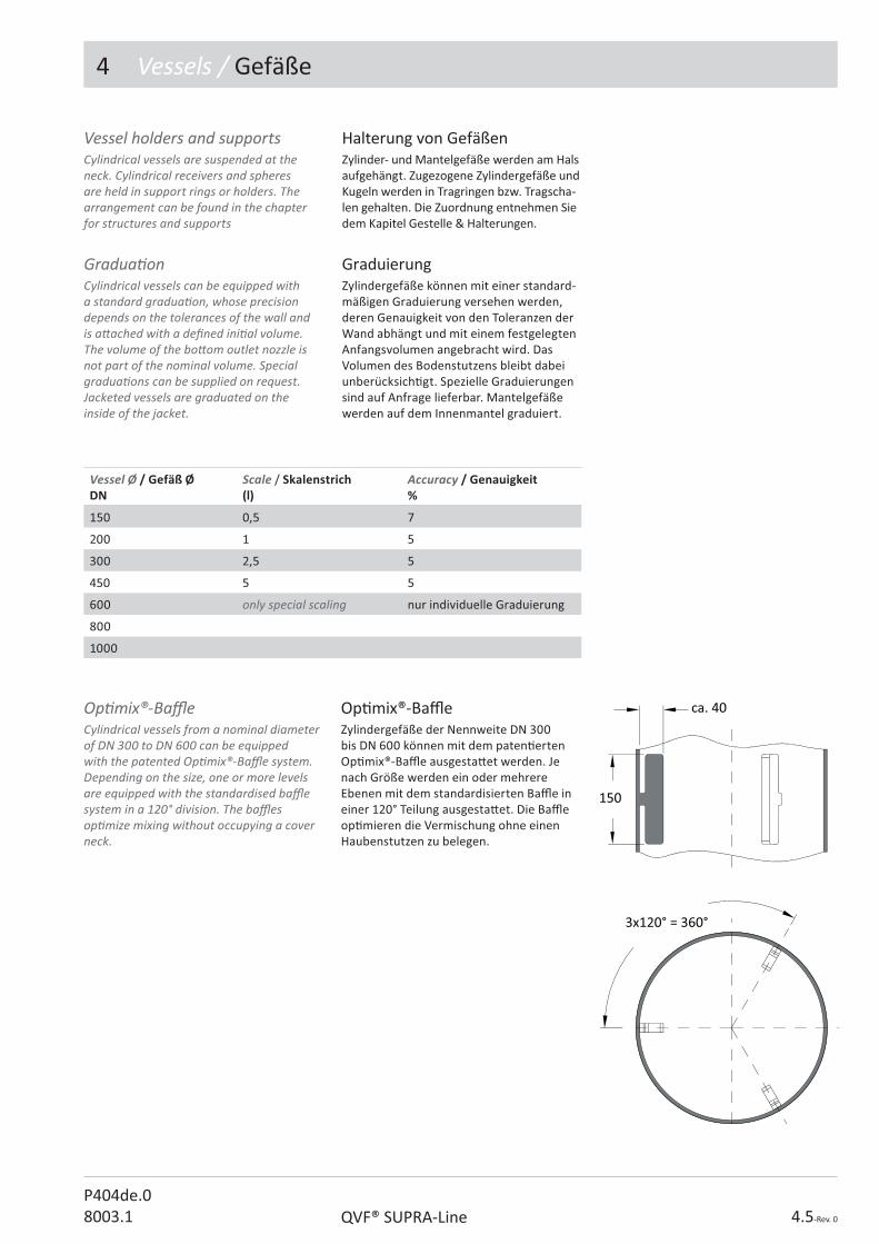
4 Vessels / Gefäße
4.5-Rev. 0QVF® SUPRA-LineP404de.08003.1
Op� mix®-Ba> eZylindergefäße der Nennweite DN 300 bis DN 600 können mit dem paten� erten Op� mix®-Ba> e ausgesta� et werden. Je nach Größe werden ein oder mehrere Ebenen mit dem standardisierten Ba> e in einer 120° Teilung ausgesta� et. Die Ba> e op� mieren die Vermischung ohne einen Haubenstutzen zu belegen.
Halterung von GefäßenZylinder- und Mantelgefäße werden am Hals aufgehängt. Zugezogene Zylindergefäße und Kugeln werden in Tragringen bzw. Tragscha-len gehalten. Die Zuordnung entnehmen Sie dem Kapitel Gestelle & Halterungen.
GraduierungZylindergefäße können mit einer standard-mäßigen Graduierung versehen werden, deren Genauigkeit von den Toleranzen der Wand abhängt und mit einem festgelegten Anfangsvolumen angebracht wird. Das Volumen des Bodenstutzens bleibt dabei unberücksich� gt. Spezielle Graduierungen sind auf Anfrage lieferbar. Mantelgefäße werden auf dem Innenmantel graduiert.
Vessel Ø / Gefäß ØDN
Scale / Skalenstrich(l)
Accuracy / Genauigkeit%
150 0,5 7
200 1 5
300 2,5 5
450 5 5
600 only special scaling nur individuelle Graduierung
800
1000
Vessel holders and supportsCylindrical vessels are suspended at the neck. Cylindrical receivers and spheres are held in support rings or holders. The arrangement can be found in the chapter for structures and supports
Gradua� onCylindrical vessels can be equipped with a standard gradua� on, whose precision depends on the tolerances of the wall and is a� ached with a de� ned ini� al volume. The volume of the bo� om outlet nozzle is not part of the nominal volume. Special gradua� ons can be supplied on request. Jacketed vessels are graduated on the inside of the jacket.
Op� mix®-Ba� eCylindrical vessels from a nominal diameter of DN 300 to DN 600 can be equipped with the patented Op� mix®-Ba� e system. Depending on the size, one or more levels are equipped with the standardised ba� e system in a 120° division. The ba� es op� mize mixing without occupying a cover neck.

4 Vessels / Gefäße
4.6-Rev. 0 QVF® SUPRA-LineP404de.0
8003.1
The hea� ng/coolingjacked may be pressurised up to +0.5 bar g in the approved temperature range. Vacuum is not permi� ed. Over pressure must be avoided in the jacket when shu� ng down the system.The permissible internal pressure of the vessels depends on the nominal diameter and corresponds to the speci� ca� ons in chapter 1.The permissible opera� ng temperature for the individual vessel types is:
Der Heiz-/Kühlmantel darf im zugelassenen Temperaturbereich mit +0,5 bar beaufschlagt werden. Vakuum ist nicht zugelassen. Es ist auf einen Druckausgleich im Mantelraum beim Abstellen der Anlage zu achten.
Der zulässige Innendruck der Gefäße ist nenn-weitenabhängig und entspricht den Angaben in Kapitel 1.
Die zulässige Betriebstemperatur für die einzelnen Gefäßtypen beträgt:
Betriebsbedingungen Mantel-gefäß
Opera� ng condi� ons of jacketed vessels
Jacket / Mantel Heat transfer � uid / Wärmeträger
Vapour (atmospheric pressure) / Dampf (Schleichdampf)
Vessel / Gefäß Tempering / Temperieren
Evapora� on / Verdampfung
Tempering / Temperieren
Evapora� on / Verdampfung
DN bar g �� (K) �� (K) �� (K) �� (K)
150 +2 80 65 45 35
200 +1 100 85 60 45
300 +1 80 70 45 35
450 +1 60 50 40 30
all / alle 0 100 90 80 60
Maximum temperature differ-Maximum temperature differ-ence between inside/jacketence between inside/jacket
Zulässige Temperaturdifferenz Zulässige Temperaturdifferenz zwischen Innenraum/Mantelzwischen Innenraum/Mantel
Die Beschichtung schränkt die maximale Tempera-tur im Mantel gem. Kapitel 1 ein. Dreiwandgefäße sind grundsätzlich beschichtet.
Der Wärmeübergang beein� usst die Wärme-spannung in der Wand, so dass für verschiedene Anwendungfälle folgende maximal zulässige Temperaturdi� erenz zwischen Produkt- und Mantelraum einzuhalten ist. Sie gilt für alle Glasgefäße mit Heiz-/Kühlmantel, auch für die Dreiwandgefäße.
Vessel type / Gefäßtyp TS TS coated / beschichtet
Jacketed vessel without outlet valve / Mantelgefäß ohne Bodenablassven� l
-80 / +200 °C -80 / +160 °C
Jacketed vessel with outlet valve / Mantelgefäß mit Bodenablassven� l
-20 / +200 °C -20 / +160 °C
Triple wall reactor / Dreiwandgefäß
- -80 / +160 °C
Glass lined reactor / Emaille Reaktor
-60 / +200 °C -
The coa� ng limits the maximum temperature in the shell according to chapter 1. Triple-wall vessels are generally coated.
Heat transfer in� uences the thermal stress in the wall, so the following maximum permis-sible temperature di� erence between product and jacket area must be maintained for the speci� ed applica� ons. It applies for all glass vessels with hea� ng/cooling jackets, also for the triple-wall vessels.

4 Vessels / Gefäße
4.7-Rev. 0QVF® SUPRA-LineP404de.08003.1
4VB
Bo� om outlet valves Bodenablassven� l
Das Bodenablassven� l ist Bestandteil des entsprechenden Gefäßes und wird mon� ert geliefert. Der PTFE Kegel dichtet totraumarm im Boden des Gefäßes ab. Beachten Sie die Hinweise zu den Betriebs-bedingungen.
Die Armatur des Bodenablassven� les ist buntmetallfrei aus Edelstahl 1.4301 gefer� gt. Das Bodenablassven� l ist op� onal mit einem integrierten PT 100 lieferbar.
Betriebsbedingungen Bodenab-lassven� lBodenablassven� le sind dem Temperatur-bereich des entsprechenden Gefäßes an-gepasst. Das Bodenablassven� l muss beim Temperieren geschlossen sein, so dass die Falten des Ven� ls nur beim Ablassvorgang den � efen Temperaturen ausgesetzt sind.
Spare parts / Ersatzteile Ref.-No.
Bo� om outlet valve DN 25 / Bodenauslaufven� l komple� DN 25 4VB 02 00? ?00 N 000
Bo� om outlet valve DN 50 / Bodenauslaufven� l komple� DN 50 4VB 05 00? ?00 N 000
Bellow replacement kit DN 25 / Reparaturset Faltenbalg DN 25 4VB 02 00? ?00 N 900
Bellow replacement kit DN 50 / Reparaturset Faltenbalg DN 50 4VB 05 00? ?00 N 900
Design key 1 + 2 Design key 1 + 2 spare part bottom outlet valvespare part bottom outlet valve
Ausführungsschlüssel 1 + 2 Ausführungsschlüssel 1 + 2 Ersatzteil BodenablassventilErsatzteil Bodenablassventil
Design key 1 / Ausführungsschlüssel 1 Code 1
Vessel without jacket / Gefäß ohne Mantel 4
Jacketed vessel / Mantelgefäß 5
Tripl wall vessel / Dreiwandgefäß 6
Design key 2 / Ausführungsschlüssel 2 Code 2
Manual / handbetä� gt 4
Pneuma� c / Pneuma� sch betä� gt 5
Manual with torque clutch / Manuell mit Überdrehsicherung 6
Manual with thermometer / handbetä� gt mit Thermometer 7
Pneuma� cal with thermometer / Pneuma� sch betä� gt mit Thermometer
8
Manual, with torque clutch and thermometer / Handbetä� gt, Überdrehsicherung, mit Thermometer
9
The bo� om outlet valve is a component for the corresponding vessel and is delivered mounted. The PTFE Plug seals with low-dead-space in the bo� om of the vessel. Please observe the opera� ng condi� ons.
The bonnet of the bo� om outlet valve is made of stainless steel 1.4301 free of nonferrous heavy metals. The bo� om drain valve can be op� onally supplied with an integrated PT 100.
Opera� ng condi� ons for the bo� om outlet valveBo� om outlet valves are adapted to the temperature range of the corresponding vessel. The bo� om outlet valve must be closed during cooling so that the folds of the valve are exposed to low temperatures only during the draining process.
1) o-Ring in case of 4VT... /
1) o-Ring-Abdichtung bei 4VT...

4 Vessels / Gefäße
4.8-Rev. 0 QVF® SUPRA-LineP404de.0
8003.1
Gefäß, KugelDie nebenstehende Abbildung zeigt mögliche Stutzenposi� onen und deren mögliche Durchmesser.
Vessel, spherical The illustra� on alongside shows possible nozzle posi� ons and the range of possible side branch diameters.
V (l) D DN1 DN2 DN3DN6
DN7DN10
5 223 80 15 ÷ 150 15 ÷ 50 15 ÷ 50
10 280 100 15 ÷ 150 15 ÷ 80 15 ÷ 80
20 350 100 15 ÷ 150 15 ÷ 80 15 ÷ 100
50 490 200 25 ÷ 200 25 ÷ 100 25 ÷ 200
100 610 200 25 ÷ 200 25 ÷150 25 ÷ 200
200 750 300 25 ÷ 300 25 ÷ 150 25 ÷ 200
500 1005 450 50 - -
To heat the contents of spherical vessels up to a nominal capacity of 50 litre they can be supplied with a borosilicate glass 3.3 jacket. This jacked is welded to the vessel at both ends.
Kugelgefäße können auf Anfrage bis zu einem Nennvolumen von 50 l auch mit einem Temperiermantel aus Borosilicatglas 3.3 geliefert werden. Dieser ist beidsei� g mit dem Innengefäß verschmolzen.
Gefäß, Kugel, TemperiermantelVessels, spherical, jacketed

4 Vessels / Gefäße
4.9-Rev. 0QVF® SUPRA-LineP404de.08003.1
Gefäß, Kugel, VorlageVessel, spherical, receiver
4VS
V (l) D DN1 DN2 L L1 Ref.-No.
5 223 80 25 375 215 4VS 08 005 000 N 000
10 280 100 25 450 250 4VS 10 010 000 N 000
20 350 100 25 550 325 4VS 10 020 000 N 000
50 490 200 25 700 400 4VS 20 050 000 N 000
100 610 200 50 825 450 4VS 20 100 000 N 000
200 750 300 50 1000 550 4VS 30 200 000 N 000
500 1005 450 80 1300 700 4VS 45 500 000 N 000
Gefäß, Kugel, Vorlage, Ven� lVessel, spherical, receiver, valve
4VS...?60
V (l) DN1 DN2 L L2 L3 Ref.-No.
5 80 25 490 391 72 4VS 08 005 ?60 N 000
10 100 25 554 456 72 4VS 10 010 ?60 N 000
20 100 25 664 566 72 4VS 10 020 ?60 N 000
50 200 25 809 711 72 4VS 20 050 ?60 N 000
100 200 50 977 832 104 4VS 20 100 ?60 N 000
200 300 50 1147 1002 104 4VS 30 200 ?60 N 000
Spare parts / Ersatzteile Ref.-No.
Glass vessel / Glas-Gefäß 4VS ?? ??? 060 N 001
Bo� om outlet valve see above / Bodenauslaufven� l s.o. 4VB...

4 Vessels / Gefäße
4.10-Rev. 0 QVF® SUPRA-LineP404de.0
8003.1
Gefäß, Kugel, universalVessel, spherical, universal
4VU
V (l) D DN1 DN2 DN3DN5
DN4 DN6 L L1 L3L5
L4 L6 Ref.-No.
5 223 80 25 40 50 50 375 215 150 175 175 4VU 08 005 000 N 000
10 280 100 25 40 80 80 450 250 205 225 225 4VU 10 010 000 N 000
20 350 100 25 40 80 80 550 325 240 260 260 4VU 10 020 000 N 000
50 490 200 25 40 80 80 700 400 310 330 330 4VU 20 050 000 N 000
100 610 200 50 50 100 100 825 450 370 415 415 4VU 20 100 000 N 000
200 750 300 50 50 100 150 1000 550 450 485 500 4VU 30 200 000 N 000
Gefäß, Kugel, universal, Ven� lVessel, spherical, universal, valve
4VU...?60
V (l) L L2 L7 Ref.-No.
5 490 391 72 4VU 08 005 ?60 N 000
10 554 456 72 4VU 10 010 ?60 N 000
20 664 566 72 4VU 10 020 ?60 N 000
50 809 711 72 4VU 20 050 ?60 N 000
100 977 832 104 4VU 20 100 ?60 N 000
200 1147 1002 104 4VU 30 200 ?60 N 000
Spare parts / Ersatzteile Ref.-No.
Glass vessel / Glas-Gefäß 4VU ?? ??? 060 N 001
Bo� om outlet valve see above / Bodenauslaufven� l s.o. 4VB...
Main dimensions like the vessel above without bo� om outlet valve.
Hauptmaße baugleich mit dem Gefäß oben, ohne Bodenauslaufven� l.

4 Vessels / Gefäße
4.11-Rev. 0QVF® SUPRA-LineP404de.08003.1
Vessel, cylindrical, universal, valve Gefäß, zylindrisch, universal, Ven� l
4VC...?6?
Gefäß, zylindrisch, universal
4VC
Vessel, cylindrical, universal
V (l) DN DN1 L L1 Ref.-No.
5 150 25 450 390 4VC 15 005 00? N 000
5 200 25 350 290 4VC 20 005 00? N 000
10 200 25 525 465 4VC 20 010 00? N 000
20 300 25 500 440 4VC 30 020 00? N 000
30 300 25 650 585 4VC 30 030 00? N 000
50 300 25 950 885 4VC 30 050 00? N 000
50 450 50 575 510 4VC 45 050 00? N 000
100 450 50 900 835 4VC 45 100 00? N 000
150 450 50 1225 1160 4VC 45 150 00? N 000
200 450 50 1550 1485 4VC 45 200 00? N 000
400 600 50 1725 1650 4VC 60 400 00? N 000
500 800 50 1250 1130 4VC 80 500 00? N 000
750 1000 80 1300 1190 4VC 11 750 00? N 000
V (l) DN DN1 L L2 L3 L10 Ref.-No.
5 150 25 555 456 72 308 4VC 15 005 ?6? N 000
5 200 25 455 356 72 183 4VC 20 005 ?6? N 000
10 200 25 630 531 72 358 4VC 20 010 ?6? N 000
20 300 25 605 506 72 283 4VC 30 020 ?6? N 000
30 300 25 750 651 72 428 4VC 30 030 ?6? N 000
50 300 25 1050 951 72 728 4VC 30 050 ?6? N 000
50 450 50 730 587 104 275 4VC 45 050 ?6? N 000
100 450 50 1105 912 104 600 4VC 45 100 ?6? N 000
150 450 50 1380 1237 104 925 4VC 45 150 ?6? N 000
200 450 50 1705 1562 104 1250 4VC 45 200 ?6? N 000
Spare parts / Ersatzteile Ref.-No.
Glass vessel / Glas-Gefäß 4VC ?? ??? 06? N 001
Bo� om outlet valve see above / Bodenauslaufven� l s.o. 4VB...
Main dimensions like the vessel above without bo� om outlet valve.
Hauptmaße baugleich mit dem Gefäß oben, ohne Bodenauslaufven� l.

4 Vessels / Gefäße
4.12-Rev. 0 QVF® SUPRA-LineP404de.0
8003.1
Gefäß, zylindrisch, Vorlage
4VC 20
Vessel, cylindrical, receiver
V (l) DN DN1 DN2 L L1 Ref.-No.
100 450 200 50 1100 1035 4VC 20 100 00? N 000
150 450 200 50 1400 1335 4VC 20 150 00? N 000
200 450 200 50 1625 1560 4VC 20 200 00? N 000
300 600 200 50 1500 1425 4VC 20 300 00? N 000
Only op� on 5 (graduated) available Nur Op� on 5 (Graduierung) verfügbar
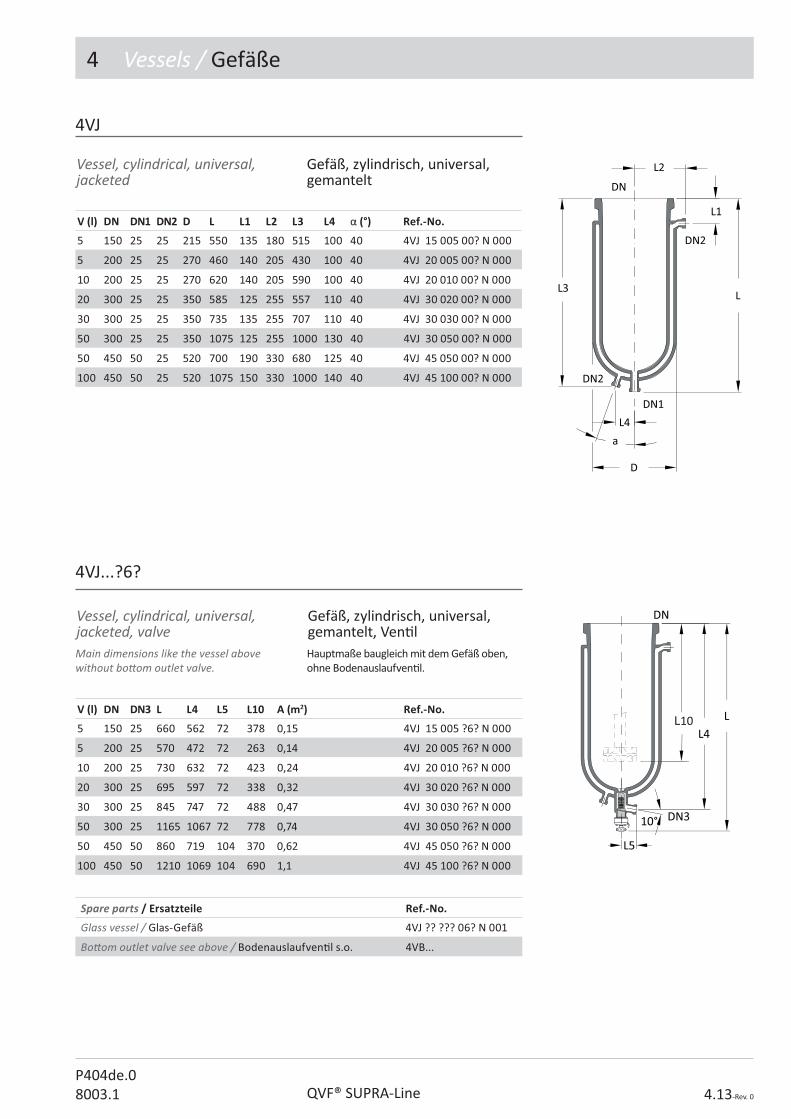
4 Vessels / Gefäße
4.13-Rev. 0
P404de.08003.1
Vessel, cylindrical, universal, jacketed, valve
Gefäß, zylindrisch, universal, gemantelt, Ven� l
4VJ...?6?
Vessel, cylindrical, universal, jacketed
Gefäß, zylindrisch, universal, gemantelt
4VJ
V (l) DN DN1 DN2 D L L1 L2 L3 L4 � (°) Ref.-No.
5 150 25 25 215 550 135 180 515 100 40 4VJ 15 005 00? N 000
5 200 25 25 270 460 140 205 430 100 40 4VJ 20 005 00? N 000
10 200 25 25 270 620 140 205 590 100 40 4VJ 20 010 00? N 000
20 300 25 25 350 585 125 255 557 110 40 4VJ 30 020 00? N 000
30 300 25 25 350 735 135 255 707 110 40 4VJ 30 030 00? N 000
50 300 25 25 350 1075 125 255 1000 130 40 4VJ 30 050 00? N 000
50 450 50 25 520 700 190 330 680 125 40 4VJ 45 050 00? N 000
100 450 50 25 520 1075 150 330 1000 140 40 4VJ 45 100 00? N 000
V (l) DN DN3 L L4 L5 L10 A (m2) Ref.-No.
5 150 25 660 562 72 378 0,15 4VJ 15 005 ?6? N 000
5 200 25 570 472 72 263 0,14 4VJ 20 005 ?6? N 000
10 200 25 730 632 72 423 0,24 4VJ 20 010 ?6? N 000
20 300 25 695 597 72 338 0,32 4VJ 30 020 ?6? N 000
30 300 25 845 747 72 488 0,47 4VJ 30 030 ?6? N 000
50 300 25 1165 1067 72 778 0,74 4VJ 30 050 ?6? N 000
50 450 50 860 719 104 370 0,62 4VJ 45 050 ?6? N 000
100 450 50 1210 1069 104 690 1,1 4VJ 45 100 ?6? N 000
Spare parts / Ersatzteile Ref.-No.
Glass vessel / Glas-Gefäß 4VJ ?? ??? 06? N 001
Bo� om outlet valve see above / Bodenauslaufven� l s.o. 4VB...
QVF® SUPRA-Line
Main dimensions like the vessel above without bo� om outlet valve.
Hauptmaße baugleich mit dem Gefäß oben, ohne Bodenauslaufven� l.

4 Vessels / Gefäße
4.14-Rev. 0 QVF® SUPRA-LineP404de.0
8003.1
Vessel, reac� on, universal
Reac� on vessels have an op� mised H/D ra� o near 1. They are equipped with an bumped boiler end. The bo� om outlet valve is in the scope of supply.
Reak� onsgefäße besitzen ein H/D-Verhältnis nahe 1 und sind mit einem Klöpperboden ausgesta� et. Das Bodenablassven� l ist im Lieferumfang enthalten.
Gefäß, Reak� on, universal
4VR
V (l) DN DN1 DN2 A (m2) Ref.-No.
6 200 25 25 0,14 4VR 20 006 ?6? N 000
10 300 25 25 0,2 4VR 30 010 ?6? N 000
25 300 25 25 0,4 4VR 30 025 ?6? N 000
50 450 50 25 0,6 4VR 45 050 ?6? N 000
Spare parts / Ersatzteile Ref.-No.
Glass vessel / Glas-Gefäß 4VR ?? ??? 06? N 001
Bo� om outlet valve see above / Bodenauslaufven� l s.o. 4VB...
Ref.-No. V (l) L L1 L2 L3 L4 L5 L6 L10
4VR 20 006 ?6? N 000 6 561 140 175 215 462 72 90 315
4VR 30 010 ?6? N 000 10 521 135 200 165 423 72 130 260
4VR 30 025 ?6? N 000 25 731 135 200 375 633 72 130 470
4VR 45 050 ?6? N 000 50 820 190 - - 682 104 - 441

4 Vessels / Gefäße
4.15-Rev. 0QVF® SUPRA-LineP404de.08003.1
4VT
The triple-wall reactor o� ers a combina� on of hea� ng/cooling and isola� ng jackets. The surrounding isola� ng jacket is evacuated to 10-6 bar and prevents the loss of heat to the environment and forma� on of the ice on the outside surface for processes below the freezing point.As the insula� on jacket is not silver-coated, the process can be observed well using a lightcolored thermal oil.All triple-wall vessels are coated with Sectrans. The bo� om outlet valve is equipped with a torque clutch.
Vessel, triple-wall-reactor Gefäß, Dreiwandreaktor
Der Dreiwandreaktor bietet die Kombina� on von Temperier- und Isoliermantel.
Der umgebende Isoliermantel ist auf 10-6 bar evakuiert und verhindert den Wärmeverlust in die Umgebung und die Eisbildung auf der Außen� äche bei Prozessen unter dem Gefrierpunkt.
Da der Isoliermantel nicht silberverspiegelt ist, kann der Prozess bei der Verwendung eines hellen Thermoöles gut beobachtet werden.
Alle Dreiwandgefäße sind mit Sectrans beschichtet, die Bodenablassarmatur mit einer Überdrehsicherung versehen
V (l) DN DN1 DN2 A (m2) Ref.-No.
6 200 25 25 0,15 4VT 20 006 ?6? L 000
10 300 25 25 0,2 4VT 30 010 ?6? L 000
25 300 25 25 0,4 4VT 30 025 ?6? L 000
50 450 40 25 0,6 4VT 45 050 ?6? L 000
Spare parts / Ersatzteile Ref.-No.
Glass vessel / Glas-Gefäß 4VT ?? ??? 06? L 001
Bo� om outlet valve see above / Bodenauslaufven� l s.o. 4VB...
Ref.-No. V (l) L L1 L2 L3 L4 L5 L6 L10
4VT 20 006 ?6? N 000 6 630 195 220 200 532 72 100 354
4VT 30 010 ?6? N 000 10 590 195 250 140 492 72 115 295
4VT 30 025 ?6? N 000 25 815 195 250 365 717 72 115 520
4VT 45 050 ?6? N 000 50 927 200 330 - 784 104 - 560
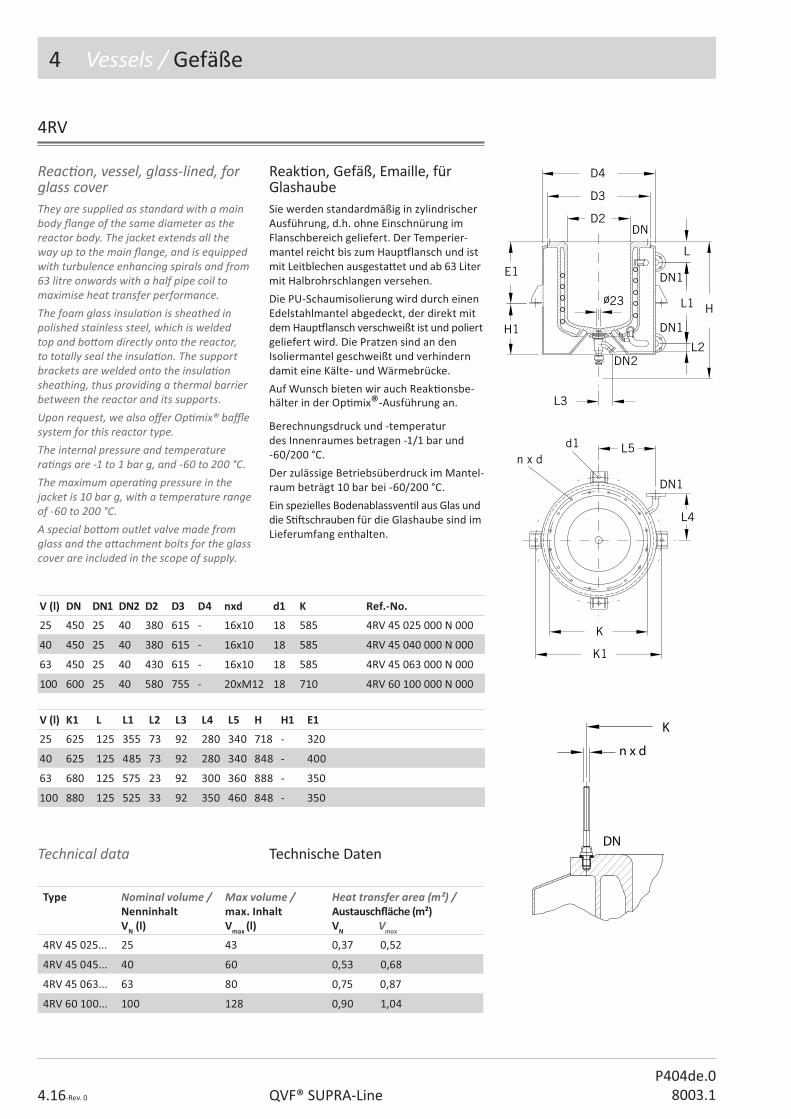
4 Vessels / Gefäße
4.16-Rev. 0 QVF® SUPRA-LineP404de.0
8003.1
They are supplied as standard with a main body � ange of the same diameter as the reactor body. The jacket extends all the way up to the main � ange, and is equipped with turbulence enhancing spirals and from 63 litre onwards with a half pipe coil to maximise heat transfer performance. The foam glass insula� on is sheathed in polished stainless steel, which is welded top and bo� om directly onto the reactor, to totally seal the insula� on. The support brackets are welded onto the insula� on sheathing, thus providing a thermal barrier between the reactor and its supports.Upon request, we also o� er Op� mix® ba� e system for this reactor type. The internal pressure and temperature ra� ngs are -1 to 1 bar g, and -60 to 200 °C. The maximum opera� ng pressure in the jacket is 10 bar g, with a temperature range of -60 to 200 °C. A special bo� om outlet valve made from glass and the a� achment bolts for the glass cover are included in the scope of supply.
Reac� on, vessel, glass-lined, for glass cover
Reak� on, Gefäß, Emaille, für GlashaubeSie werden standardmäßig in zylindrischer Ausführung, d.h. ohne Einschnürung im Flanschbereich geliefert. Der Temperier-mantel reicht bis zum Haup# lansch und ist mit Leitblechen ausgesta� et und ab 63 Liter mit Halbrohrschlangen versehen.
Die PU-Schaumisolierung wird durch einen Edelstahlmantel abgedeckt, der direkt mit dem Haup# lansch verschweißt ist und poliert geliefert wird. Die Pratzen sind an den Isoliermantel geschweißt und verhindern damit eine Kälte- und Wärmebrücke.
Auf Wunsch bieten wir auch Reak� onsbe-hälter in der Op� mix®-Ausführung an.
Berechnungsdruck und -temperatur des Innenraumes betragen -1/1 bar und -60/200 °C.
Der zulässige Betriebsüberdruck im Mantel-raum beträgt 10 bar bei -60/200 °C.
Ein spezielles Bodenablassven� l aus Glas und die S� � schrauben für die Glashaube sind im Lieferumfang enthalten.
V (l) DN DN1 DN2 D2 D3 D4 nxd d1 K Ref.-No.
25 450 25 40 380 615 - 16x10 18 585 4RV 45 025 000 N 000
40 450 25 40 380 615 - 16x10 18 585 4RV 45 040 000 N 000
63 450 25 40 430 615 - 16x10 18 585 4RV 45 063 000 N 000
100 600 25 40 580 755 - 20xM12 18 710 4RV 60 100 000 N 000
V (l) K1 L L1 L2 L3 L4 L5 H H1 E1
25 625 125 355 73 92 280 340 718 - 320
40 625 125 485 73 92 280 340 848 - 400
63 680 125 575 23 92 300 360 888 - 350
100 880 125 525 33 92 350 460 848 - 350
Technical data Technische Daten
Type Nominal volume / Nenninhalt VN (l)
Max volume / max. Inhalt Vmax (l)
Heat transfer area (m²) /Austausch� äche (m²)VN Vmax
4RV 45 025... 25 43 0,37 0,52
4RV 45 045... 40 60 0,53 0,68
4RV 45 063... 63 80 0,75 0,87
4RV 60 100... 100 128 0,90 1,04
4RV

4 Vessels / Gefäße
4.17-Rev. 0QVF® SUPRA-LineP404de.08003.1
4MC
Vessel, cylindrical, mobile Gefäß, Zylinder, fahrbar
V (l) DN DN1 D H Ref.-No.without pump / ohne Pumpe
30 300 50 821 1545 4MC 30 030 000 N 000
50 300 50 821 1795 4MC 30 050 000 N 000
100 450 50 962 1945 4MC 45 100 000 N 000
150 450 50 962 2245 4MC 45 150 000 N 000
200 450 50 962 2545 4MC 45 200 000 N 000
4MS
Vessel, spherical, mobile Gefäß, Kugel, fahrbar
V (l) DN1 D H Ref.-No.without pump / ohne Pumpe
50 200 962 1370 4MS 20 050 000 N 000
100 200 962 1470 4MS 20 100 000 N 000
200 300 1245 1700 4MS 30 200 000 N 000
Auf Wunsch kann das fahrbare Gefäß mit Verrohrung und einer Förderpumpe ange-boten werden.
A pump and connec� ng pipelines can be o� ered on request.
Auf Wunsch kann das fahrbare Gefäß mit Verrohrung und einer Förderpumpe ange-boten werden.
A pump and connec� ng pipelines can be o� ered on request.

4 Vessels / Gefäße
4.18-Rev. 0 QVF® SUPRA-LineP404de.0
8003.1
Cover, receivers
4CV
DN DN1 DN2 d L L1 L2 Type Ref.-No.
100 50 2 x 15 - 175 79 106 A 4CV 10 005 330 N 000
150 50 2 x 25 - 200 113 133 A 4CV 15 005 330 N 000
200 50 2 x 25 - 175 126 126 B 4CV 20 005 330 N 000
200 - 3 x 40 150 - 175 - C 4CV 20 000 330 N 000
300 50 2 x 25 - 225 161 161 B 4CV 30 005 330 N 000
300 80 3 x 40 245 250 225 - C 4CV 30 008 330 N 000
450 50 2 x 40 - 325 221 221 B 4CV 45 005 330 N 000
600 50 2 x 40 - 375 264 264 B 4CV 60 005 330 N 000
800 80 2 x 80 - 550 389 389 B 4CV 80 008 330 N 000
1000 80 2 x 80 - 650 488 413 B 4CV 11 008 330 N 000
Haube, Vorlage

4 Vessels / Gefäße
4.19-Rev. 0QVF® SUPRA-LineP404de.08003.1
Cover, central s� rrer branch Haube, Rührwerksstutzen, zentrisch
4CC
DN DN1 DN2 DN3 DN4 d L L1 L2 L3 L4 Type Ref.-No.
300 50 80 3 x 40 - 245 250 188 188 225 - A 4CC 30 005 330 N 000
300 80 80 2 x 40 - 245 250 188 188 225 - B 4CC 30 008 330 N 000
450 50 150 2 x 40 50 350 325 262 259 285 285 C 4CC 45 005 330 N 000
450 80 150 2 x 40 50 350 325 262 259 285 285 C 4CC 45 008 330 N 000
450 100 150 2 x 40 50 350 350 262 259 285 285 C 4CC 45 010 330 N 000
600 50 150 2 x 40 50 400 375 291 290 335 335 C 4CC 60 005 330 N 000
600 80 150 2 x 40 50 400 375 291 290 335 335 C 4CC 60 008 330 N 000
600 100 150 2 x 40 50 400 400 291 290 335 335 C 4CC 60 010 330 N 000
800 80 150 3 x 80 - 450 550 386 386 525 - C 4CC 80 008 330 N 000
800 100 150 3 x 80 - 450 550 386 386 525 - C 4CC 80 010 330 N 000
800 150 150 3 x 80 - 450 575 386 386 525 - C 4CC 80 015 330 N 000
1000 80 150 3 x 80 - 500 650 487 412 600 - C 4CC 11 008 330 N 000
1000 100 150 3 x 80 - 500 650 487 412 600 - C 4CC 11 010 330 N 000
1000 150 150 3 x 80 - 500 650 487 412 600 - C 4CC 11 015 330 N 000

4 Vessels / Gefäße
4.20-Rev. 0 QVF® SUPRA-LineP404de.0
8003.1
Cover, excentric s� rrer branch Haube, Rührwerksstutzen, exzentrisch
4CE
DN DN1 DN2 DN3 d L L1 L2 L3 L4 Ref.-No.
200 50 50 - - 200 40 139 139 - 4CE 20 005 330 N 000
300 50 80 40 245 250 60 188 188 225 4CE 30 005 330 N 000
Cover, vessel, reac� on Haube, Gefäß, Reak� on
4CR
DN DN1 DN2 DN3 DN4 L L1 L2 L3 L4 Ref.-No.
450 80 100 80 50 325 175 247 232 285 4CR 45 008 330 N 000
600 100 100 80 50 400 200 288 291 335 4CR 60 010 330 N 000

4 Vessels / Gefäße
4.21-Rev. 0QVF® SUPRA-LineP404de.08003.1
Dip pipe, straight Einleitrohr, gerade
4DS
DN DN1 d L L1 Type Ref.-No.
25 25 18 100 100 A 4DS 02 010 330 N 000
40 25 28 100 100 B 4DS 04 010 330 N 000
40 25 28 100 300 B 4DS 04 030 330 N 000
40 25 28 100 500 B 4DS 04 050 330 N 000
40 25 28 100 650 B 4DS 04 065 330 N 000
40 25 28 100 850 B 4DS 04 085 330 N 000
50 25 33 100 100 B 4DS 05 010 330 N 000
50 25 33 100 300 B 4DS 05 030 330 N 000
50 25 33 100 525 B 4DS 05 052 330 N 000
50 25 33 100 650 B 4DS 05 065 330 N 000
50 25 33 100 875 B 4DS 05 087 330 N 000
4DA
Dip pipe, angled Einleitrohr, abgewinkelt
DN DN1 d L L1 L2 Ref.-No.
25 15 13 100 95 115 4DA 02 011 330 N 000
25 15 13 100 115 150 4DA 02 015 330 N 000
40 25 28 100 115 115 4DA 04 011 330 N 000
40 25 28 100 135 165 4DA 04 016 330 N 000
40 25 28 100 150 260 4DA 04 026 330 N 000
40 25 28 100 150 345 4DA 04 034 330 N 000
50 25 33 100 150 150 4DA 05 015 330 N 000
50 25 33 100 150 245 4DA 05 024 330 N 000
50 25 33 100 150 335 4DA 05 033 330 N 000
50 25 33 100 150 435 4DA 05 043 330 N 000
80 50 59 125 200 265 4DA 08 026 330 N 000
80 50 59 125 200 365 4DA 08 036 330 N 000
80 50 59 125 275 525 4DA 08 052 330 N 000
Für 45°-Stutzen ist diese Ausführung zu wählen.
This version should be selected for use with branches aligned at 45°.

4 Vessels / Gefäße
4.22-Rev. 0 QVF® SUPRA-LineP404de.0
8003.1
The cyclones described here are designed for the separa� on of droplets from gases and vapours.
Cyclone Zyklone
Zyklone eignen sich für die Tropfenab-scheidung aus Gasen und Dämpfen.
4CY
DN DN1 DN2 DN3 L L1 L2 L3 L4 L5 Ref.-No.
100 40 25 80 714 560 180 284 125 34 4CY 10 004 333 N 000
150 50 25 100 839 655 235 349 150 53 4CY 15 005 333 N 000
200 80 25 150 1119 915 320 429 200 64 4CY 20 008 333 N 000
300 100 25 150 1429 1225 405 489 275 100 4CY 30 010 333 N 000

4 Vessels / Gefäße
4.23-Rev. 0
P404de.08003.1 QVF®SUPRA-Line
4HS
Separator Abscheider
The con� nuous separa� on of immiscible liquids with di� erent densi� es requires low � ow rates and the largest possible phase-interface between the light and heavy phase. Horizontal separators sa� sfy these requirements perfectly. The table below indicates typical � gures for maximum possible throughputs in these separators for medium to low interfacial tension and a minimum �� of 100 kg/m³. Flow rates for built-in over� ow valves are based on water at 20 °C.
Die kon� nuierliche Trennung nicht mischbarer Flüssigkeiten mit unterschiedlichen Dichten setzt geringe Strömungsgeschwindigkeiten und eine möglichst große Phasengrenz� äche zwischen leichter und schwerer Phase vor-aus. Diese Forderungen werden in idealer Weise von liegenden Abscheidern erfüllt.
Richtwerte für die maximal möglichen Durchsätze der Abscheider, bei kleinen bis mi� leren Grenz� ächenspannungen und einer minimalen Dichtedi� erenz von 100 kg/m³, und für die innenliegenden Überlaufven� le bezogen auf Wasser bei 20 °C, können Sie der nachstehenden Tabelle entnehmen.
Se� ler / Abscheider Over� ow valve / Überlaufven� l
DN Vmax �(S.P.+L.P.) l/h
Vmax S.P. l/h
100 200 400
150 400 600
200 800 900
300 1700 1600
450 4000 3200
600 7000 5000
800 12000 7000
S.P = heavy phaseL.P = light phase
S.P = Schwere PhaseL.P = Leichte Phase

4 Vessels / Gefäße
4.24-Rev. 0 QVF® SUPRA-LineP404de.0
8003.1
Separator, horizontal, without over� ow valve
Abscheider, liegend, ohne Überlaufven� l
DN DN1 DN2 DN3 DN4
L L1 L2 L3 L4 L5 Ref.-No.
100 25 15 950 150 500 200 110 100 4HS 10 000 333 N 000
150 40 25 1000 200 500 200 140 100 4HS 15 000 333 N 000
200 80 40 1580 200 1000 245 175 120 4HS 20 000 333 N 000
300 100 50 2190 250 1500 300 230 150 4HS 30 000 333 N 000
450 150 80 2950 350 2000 355 330 175 4HS 45 000 333 N 000
Dimensions Einbaumaße
DN E1 E2 E3 E4 d
100 174 452 110 165 13
150 216 468 200 208 14
200 218 964 200 243 14
300 269 1463 200 295 14
450 650 1400 300 280 18
4HS
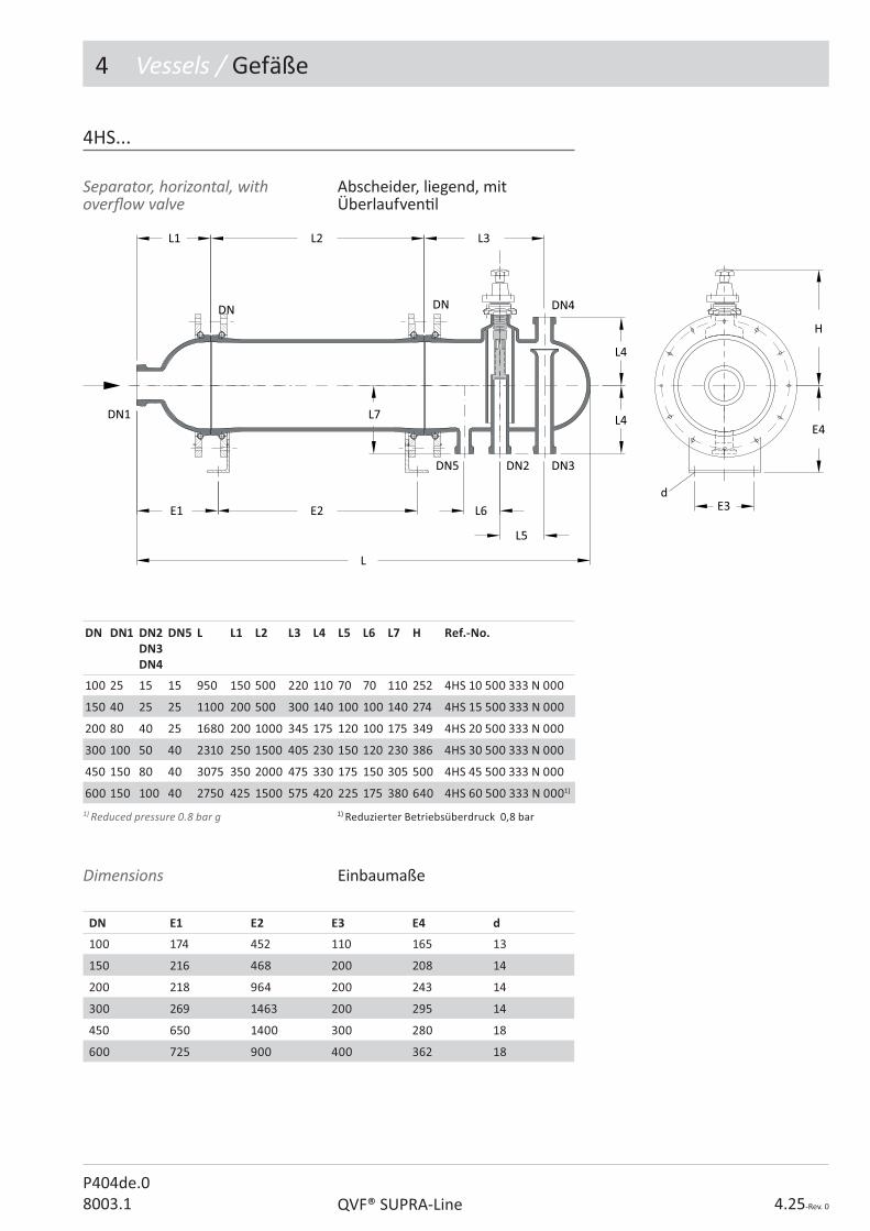
4 Vessels / Gefäße
4.25-Rev. 0QVF® SUPRA-LineP404de.08003.1
Separator, horizontal, with over� ow valve
Abscheider, liegend, mit Überlaufven� l
DN DN1 DN2 DN3DN4
DN5 L L1 L2 L3 L4 L5 L6 L7 H Ref.-No.
100 25 15 15 950 150 500 220 110 70 70 110 252 4HS 10 500 333 N 000
150 40 25 25 1100 200 500 300 140 100 100 140 274 4HS 15 500 333 N 000
200 80 40 25 1680 200 1000 345 175 120 100 175 349 4HS 20 500 333 N 000
300 100 50 40 2310 250 1500 405 230 150 120 230 386 4HS 30 500 333 N 000
450 150 80 40 3075 350 2000 475 330 175 150 305 500 4HS 45 500 333 N 000
600 150 100 40 2750 425 1500 575 420 225 175 380 640 4HS 60 500 333 N 0001)
Dimensions Einbaumaße
DN E1 E2 E3 E4 d
100 174 452 110 165 13
150 216 468 200 208 14
200 218 964 200 243 14
300 269 1463 200 295 14
450 650 1400 300 280 18
600 725 900 400 362 18
4HS...
1) Reduced pressure 0.8 bar g 1) Reduzierter Betriebsüberdruck 0,8 bar

4 Vessels / Gefäße
4.26-Rev. 0 QVF® SUPRA-LineP404de.0
8003.1
Special features of these items are resistance to fouling, their ability to break down foam and their high e� ciency with a limi� ng drop size of � 20 �m and a maximum � ow volume, based on the empty pipe, of 25 m3/m2h. If the number of the required individual elements di� ers from the � gure shown in the table below, please specify the number required when ordering.
Coalescer, horizontal separators
Besondere Merkmale dieser Elemente sind ihre Unemp� ndlichkeit gegen Schmutz, ihre Fähigkeit, Mulm abzubauen und ihre hohe spezi� sche Leistung mit einer Grenztropfen-größe von @ 20 ;m und einer maximalen Volumenstrombelastung, bezogen auf das leere Rohr, von 25 m3/m2h.
Weicht die Anzahl der benö� gten Einzel-elemente von den Angaben in nachstehender Tabelle ab, so ist dies bei Au� ragserteilung anzugeben.
Koaleszenzhilfe, Abscheider, horizontal
4CO
DN L L1 L2 Number of elementsAnzahl Segmente
Capacity (l/h)Durchsatz (l/h)
Ref.-No.
100 360 100 500 4 200 4CO 10 000 000 N 000
150 360 100 500 4 400 4CO 15 000 000 N 000
200 540 150 1000 6 800 4CO 20 000 000 N 000
300 540 150 1000 6 1700 4CO 30 000 000 N 000
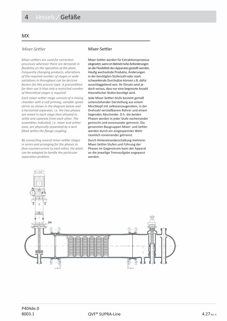
4 Vessels / Gefäße
4.27-Rev. 0QVF® SUPRA-LineP404de.08003.1
Mixer-se� lers are used for extrac� on processes wherever there are demands in � exibility on the opera� on of the plant. Frequently changing products, altera� ons of the required number of stages or wide varia� ons in throughput can be decisive factors for this process type. A precondi� on for their use is that only a restricted number of theore� cal stages is required.Each mixer-se� ler stage consists of a mixing chamber with a self-priming, variable speed s� rrer as shown in the diagram below and a horizontal separator, i.e. the two phases are mixed in each stage then allowed to se� le and separate from each other. The assemblies indicated, i.e. mixer and se� ler zone, are physically separated by a weir � � ed within the � ange coupling.
By connec� ng several mixer-se� ler stages in series and arranging for the phases to � ow countercurrent to each other, the plant can be adapted to handle the par� cular separa� on problem.
Mixer-Se� ler werden für Extrak� onsprozesse eingesetzt, wenn im Betrieb hohe Anforderungen an die Flexibilität des Apparates gestellt werden. Häu� g wechselnde Produkte, Änderungen in der benö� gten Stufenzahl oder stark schwankende Durchsätze können z.B. dafür ausschlaggebend sein. Ihr Einsatz setzt je-doch voraus, dass nur eine begrenzte Anzahl theore� scher Stufen benö� gt wird.
Jede Mixer-Se� ler-Stufe besteht gemäß untenstehender Darstellung aus einem Mischkopf mit selbstansaugendem, in der Drehzahl verstellbarem Rührer und einem liegenden Abscheider. D.h. die beiden Phasen werden in jeder Stufe nacheinander gemischt und voneinander getrennt. Die genannten Baugruppen Mixer- und Se� ler werden durch ein eingespanntes Wehr räumlich voneinander getrennt.
Durch Hintereinanderschaltung mehrerer Mixer-Se� ler-Stufen und Führung der Phasen im Gegenstrom kann der Apparat an die jeweilige Trennaufgabe angepasst werden.
Mixer-Se� lerMixer-Se� ler
MX
DN

4 Vessels / Gefäße
4.28-Rev. 0 QVF® SUPRA-LineP404de.0
8003.1
These hea� ng mantles are subdivided into several hea� ng zones each of which is equipped with a temperature probe so that the surface temperature of the vessel can be monitored. These work in conjunc� on with the control unit included in the supply to avoid local hot spots. The control unit also includes energy regulators to control the heat input separately for each hea� ng zone depending on the liquid level.Product temperature control is possible via a resistance thermometer (not included). These hea� ng mantles must not be used in Ex-zones
Hea� ng mantle for spherical vessels
Die Heizhauben sind in mehrere Heizzonen unterteilt, die jeweils mit einem Temperatur-fühler zur Überwachung der maximalen Ober� ächentemperatur des Kugelgefäßes ausgesta� et sind. In Verbindung mit dem zum Lieferumfang gehörenden Steuergerät können so örtliche Überhitzungen vermieden werden. Mit Hilfe der Leistungssteller am Steuergerät lässt sich außerdem die Wärme-zufuhr je nach Flüssigkeitsstand für jede Heizzone separat einstellen.
Über ein Widerstandsthermometer (nicht im Lieferumfang) ist die Regelung der Produkt-temperatur möglich.
Die Heizhauben haben keine Ex-Zonen-Zulassung.
Heizhaube, Gefäß, Kugel
4HM
Nominal capacity of spherical vessel (l)Nenninhalt desKugelgefäßes (l)
powerLeistungkW
Voltage VSpannung V (50 Hz)
Number of hea� ng zonesAnzahl der Heizkreise
10 1,6 230 3
20 2,4 230 3
50 4,5 230/400, 3Ph 3
100 6,0 230/400, 3Ph 4
200 9,0 230/400, 3Ph 5
V Vessel / Kugel (l)
DN D D1 d2 d3 d4 L H Ref.-No.
10 25/40 280 370 313 120 4 x M12 10 185 4HM 00 010 000 R 000
20 25/40 350 440 388 120 4 x M12 15 230 4HM 00 020 000 R 000
50 25/40 490 580 555 120 4 x M12 20 300 4HM 00 050 000 R 000
100 40/50 610 700 676 120 4 x M12 20 380 4HM 00 100 000 R 000
200 50 750 840 821 140 4 x M12 20 445 4HM 00 200 000 R 000

P405d.08003.1
��������������� ������
2. Rohrleitungen
3. Armaturen
4. Gefäße
5. WÄRMEÜBERTRAGER
6. Kolonnenbauteile
7. Rührwerke
8. Mess- und Regelgeräte
9. Verbindungen
10. Gestelle und Halterungen

5 Heat Exchanger / Wärmeübertrager
5.2-Rev. 0 QVF® SUPRA-LineP405de.0
8003.1
Contents / Inhaltsverzeichnis
Ref.-No. Reference Ar� kel-Bezeichnung Page / Seite
5HC Coil type, heat exchanger Schlangen-Wärmeübertrager 4-7
5BC Boiler, coil type Heizer, Schlange 8
5HI Heat exchanger, immersion, glass Wärmeübertrager, Einsatz, Schlange 10
5CL Cooler, liquid Flüssigkeitskühler 11
5CV Condenser, vent Nachkondensator 12
5AT Adaptor, tube, 90°, 1.4581 Adapter, Schlauch, 90°, 1.4581 13
5HT Heat exchanger, tube & shell Rohrbündel-Wärmeübertrager 14-21
5HI Heat exchanger, immersion, coil type Einsatzheizer, Schlange 22
5HI Heat exchanger, immersion, ring type Wärmeübertrager, Einsatz, Kreisring 23
5HI Heat exchanger, immersion, bayonet type Wärmeübertrager, Kerzen-Einsatzheizer 24
Technical data are subject to change. All rights reserved. Copyright © De Dietrich Process Systems GmbH.
Technische Änderungen und Irrtümer vor-behalten. Copyright © De Dietrich Process Systems GmbH.

5 Heat Exchanger / Wärmeübertrager
5.3-Rev. 0QVF® SUPRA-LineP405de.08003.1
Op� on key Variantenschlüssel
N No op� on / Standard
L Sectrans / Sectrans
Design key 1 Heat transfer areaExample:
Ausführungsschlüssel 1 Wärmeübertrager� ächeBeispiel:
heat transfer area / Austausch� äche m²x10 (3,81m²x10=038) 038
Ar� cle group / Ar� kelschlüssel
Nominal diameter key / Nennweitenschlüssel
Design key 1 / Ausführungsschlüssel 1
Design key 2 / Ausführungsschlüssel 2
Op� on key / Variantenschlüssel
Sub item / Unterposi� on
5AA 00 000 000 A 000
QVF® SUPRA-Line Reference No.
Ar� cles of the QVF® SUPRA-Line component system are de� ned by a reference code of 15 characters. The code is led by the number of the catalogue sec� on and 2 le� ers linked to the English descrip� on.All other characters are used to specify the ar� cle in its group. The remaining posi� ons are � lled with “0”.In case a reference number has to be completed a “?” is shown. The right number is indicated in the op� on key table of the catalogue sec� on or the ar� cle group itself.Free space between the reference segments is not a part of the reference number it is only set to read the number easily.
QVF® SUPRA-Line Ar� kelnummern
Die Ar� kel des neuen QVF® SUPRA-Line Bauteileprogramms werden über eine 15-stellige Ar� kelnummer de� niert. Das 1. Segment - die Ar� kelgruppe - besteht aus der Kapitelzi� er und zwei Buchstaben die aus der englischen Bezeichnung des Ar� kels abgeleitet sind.
Alle weiteren Segmente dienen zur Di� eren-zierung der Ar� kel innerhalb einer Ar� kel-gruppe. Nicht benö� gte Stellen werden mit 0 aufgefüllt.
Zu ergänzende Stellen sind mit „?“ gekenn-zeichnet. Die wählbaren Bauteil-A� ribute sind ar� kelbezogen in einer Code-Tabelle aufgeführt.
Leerzeichen zwischen den einzelnen Segmenten dienen der besseren Lesbarkeit und sind kein Bestandteil der Ar� kelnummer.

5 Heat Exchanger / Wärmeübertrager
5.4-Rev. 0 QVF® SUPRA-LineP405de.0
8003.1
Service connec� on coil heat exchangerWhen installing coil-type heat exchangers appropriate precau� ons should be taken. The main points to be taken into account when planning are:
• The use of hoses or bellows on the cooling water connec� ons to avoid imposing stresses.
• Fi� ng a pressure reducing valve (if necessary), control valve, non-return valve (not when used under re-cool condi� ons) and pressure gauge immediately before the heat exchanger.
• Free drainage of the cooling water from the coils, if it is not possible to provide other means of ensuring that the permissible opera� ng pressure is not exceeded.
• Ball valves or other rapid opening valves must not be used in the inlet lines to coil type heat exchangers to avoid any water hammer in the coil.
• Up to a nominal bore of DN 150 coil type heat exchangers can also be installed horizontally (with a slight fall).
Coil type, heat exchangersThese items have a coil ba� ery welded to the jacket. This is of importance for a plant which has to be conform to GMP requirements since it ensures that the product and the coolant cannot come into contact with each other.
Anschluss Schlangenwärmeüber-tragerBeim Anschließen eines Schlangen-Wärme-übertragers sind die folgenden Hinweise zu beachten. Wesentliche Gesichtspunkte für die Planung sind:
• Spannungsfreie Kühlwasseranschlüsse mi� els Schläuchen oder Faltenbälgen.
• Einbau eines Druckminderven� ls (falls erforderlich), Regelven� ls, Rückschlagven� ls (nicht bei Rückkühlbetrieb) und Manometers vor dem Schlangen-Wärmeübertrager.
• Freier Auslauf des Kühlwassers hinter dem Schlangen-Wärmeübertrager, sofern nicht durch andere Maßnahmen eine Überschreitung des zulässigen Betriebsüberdruckes sichergestellt werden kann.
• Keine Kugelhähne oder andere schnell ö� nende Ven� le vor dem Schlangen-Wärmeübertrager, um Druckstöße in der Schlange zu vermeiden.
• Bis zur Nennweite DN 150 können die Schlangen-Wärmeübertrager auch waagerecht (mit leichtem Gefälle) angeordnet werden.
Schlangen-WärmeübertragerDas Schlangenpaket ist mit dem Mantel-rohr verschmolzen. Dadurch ist eine sichere Trennung von Produkt und Kühlmedium gewährleistet.
5 HC/BC/HI/CL/CV
Permissible opera� ng condi� onsWhile the maximum permissible opera� ng temperature for borosilicate glass 3.3 heat exchanger bodies is generally 200 °C (�=180 K), the maximum permissible opera� ng pressure is governed by the main nominal size of the component.The permissible pressure di� erence across the wall of the coils as a func� on of the temperature di� erence at that point is indicated in the following diagrams. The speci� ed � is the di� erence between the temperature of the shell side medium and the medium inside the coils. The permissible pressure di� erence is valid up to an overall heat transfer coe� cient of k = 290 W/m²K which covers most prac� cal applica� ons.
Zulässige BetriebsbedingungenWährend die zulässige Betriebstempertur für die Mäntel der Wärmeübertrager aus Borosilicatglas 3.3 generell 200 °C (�[ = 180 K) beträgt, ist deren zulässiger Betriebsüberdruck von der Hauptnennweite abhängig.
Der zulässige Di� erenzdruck über die Wandung der Schlangen in Abhängigkeit von der dort herrschenden Temperaturdi� erenz kann nachstehenden Diagrammen entnommen werden. Das angegebene �[ ist hierbei die Di� erenz zwischen der Temperatur des Mediums im Mantelraum und der Temperatur des Mediums in der Schlange. Diese Angaben gelten bis zu einem Wärmedurchgangs-koe� zient von k = 290 W/m²K, welche die in der Praxis vorkommenden Fälle weitest-gehend abdeckt.
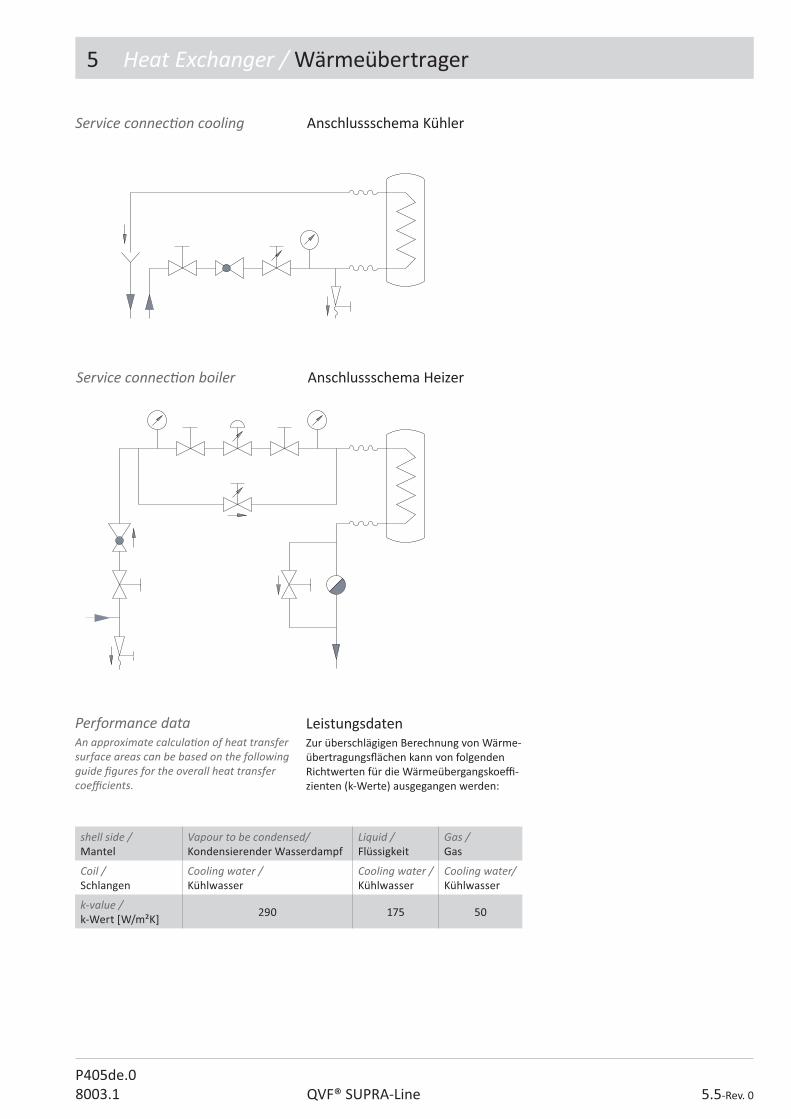
5 Heat Exchanger / Wärmeübertrager
5.5-Rev. 0QVF® SUPRA-LineP405de.08003.1
Service connec� on cooling Anschlussschema Kühler
Service connec� on boiler Anschlussschema Heizer
LeistungsdatenZur überschlägigen Berechnung von Wärme-übertragungs� ächen kann von folgenden Richtwerten für die Wärmeübergangskoe� -zienten (k-Werte) ausgegangen werden:
Performance dataAn approximate calcula� on of heat transfer surface areas can be based on the following guide � gures for the overall heat transfer coe� cients.
shell side / Mantel
Vapour to be condensed/ Kondensierender Wasserdampf
Liquid / Flüssigkeit
Gas / Gas
Coil / Schlangen
Cooling water /Kühlwasser
Cooling water / Kühlwasser
Cooling water/ Kühlwasser
k-value /k-Wert [W/m²K]
290 175 50
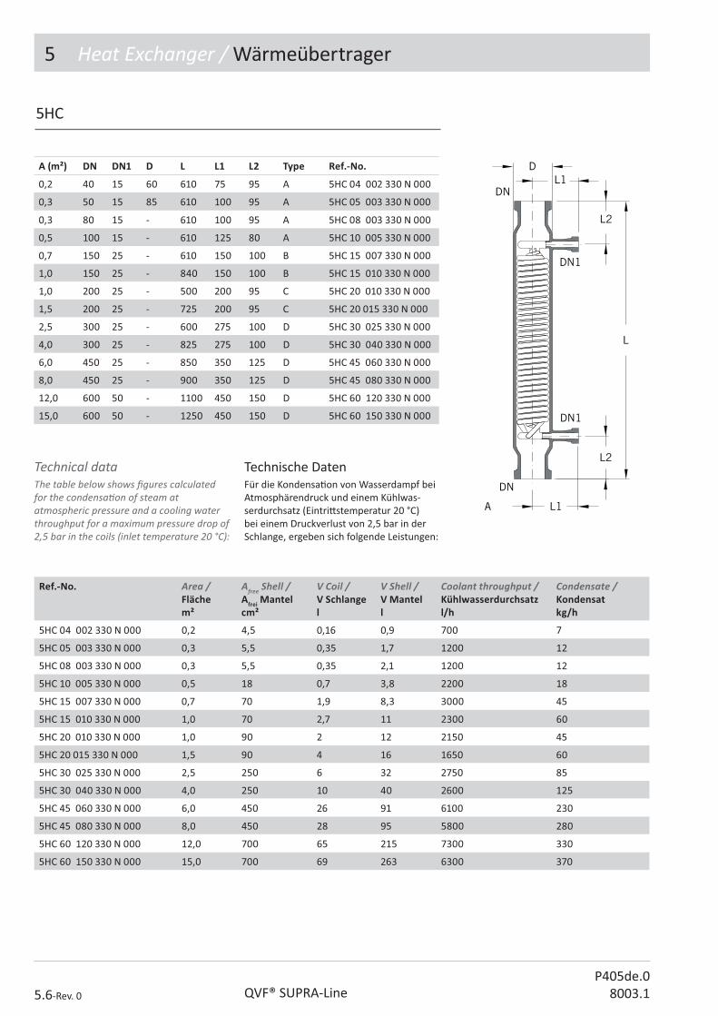
5 Heat Exchanger / Wärmeübertrager
5.6-Rev. 0 QVF® SUPRA-LineP405de.0
8003.1
Technische DatenFür die Kondensa� on von Wasserdampf bei Atmosphärendruck und einem Kühlwas-serdurchsatz (Eintri� stemperatur 20 °C) bei einem Druckverlust von 2,5 bar in der Schlange, ergeben sich folgende Leistungen:
Technical dataThe table below shows � gures calculated for the condensa� on of steam at atmospheric pressure and a cooling water throughput for a maximum pressure drop of 2,5 bar in the coils (inlet temperature 20 °C):
5HC
A (m²) DN DN1 D L L1 L2 Type Ref.-No.
0,2 40 15 60 610 75 95 A 5HC 04 002 330 N 000
0,3 50 15 85 610 100 95 A 5HC 05 003 330 N 000
0,3 80 15 - 610 100 95 A 5HC 08 003 330 N 000
0,5 100 15 - 610 125 80 A 5HC 10 005 330 N 000
0,7 150 25 - 610 150 100 B 5HC 15 007 330 N 000
1,0 150 25 - 840 150 100 B 5HC 15 010 330 N 000
1,0 200 25 - 500 200 95 C 5HC 20 010 330 N 000
1,5 200 25 - 725 200 95 C 5HC 20 015 330 N 000
2,5 300 25 - 600 275 100 D 5HC 30 025 330 N 000
4,0 300 25 - 825 275 100 D 5HC 30 040 330 N 000
6,0 450 25 - 850 350 125 D 5HC 45 060 330 N 000
8,0 450 25 - 900 350 125 D 5HC 45 080 330 N 000
12,0 600 50 - 1100 450 150 D 5HC 60 120 330 N 000
15,0 600 50 - 1250 450 150 D 5HC 60 150 330 N 000
Ref.-No. Area / Flächem²
Afree Shell /Afrei Mantelcm²
V Coil / V Schlangel
V Shell / V Mantell
Coolant throughput / Kühlwasserdurchsatzl/h
Condensate /Kondensatkg/h
5HC 04 002 330 N 000 0,2 4,5 0,16 0,9 700 7
5HC 05 003 330 N 000 0,3 5,5 0,35 1,7 1200 12
5HC 08 003 330 N 000 0,3 5,5 0,35 2,1 1200 12
5HC 10 005 330 N 000 0,5 18 0,7 3,8 2200 18
5HC 15 007 330 N 000 0,7 70 1,9 8,3 3000 45
5HC 15 010 330 N 000 1,0 70 2,7 11 2300 60
5HC 20 010 330 N 000 1,0 90 2 12 2150 45
5HC 20 015 330 N 000 1,5 90 4 16 1650 60
5HC 30 025 330 N 000 2,5 250 6 32 2750 85
5HC 30 040 330 N 000 4,0 250 10 40 2600 125
5HC 45 060 330 N 000 6,0 450 26 91 6100 230
5HC 45 080 330 N 000 8,0 450 28 95 5800 280
5HC 60 120 330 N 000 12,0 700 65 215 7300 330
5HC 60 150 330 N 000 15,0 700 69 263 6300 370
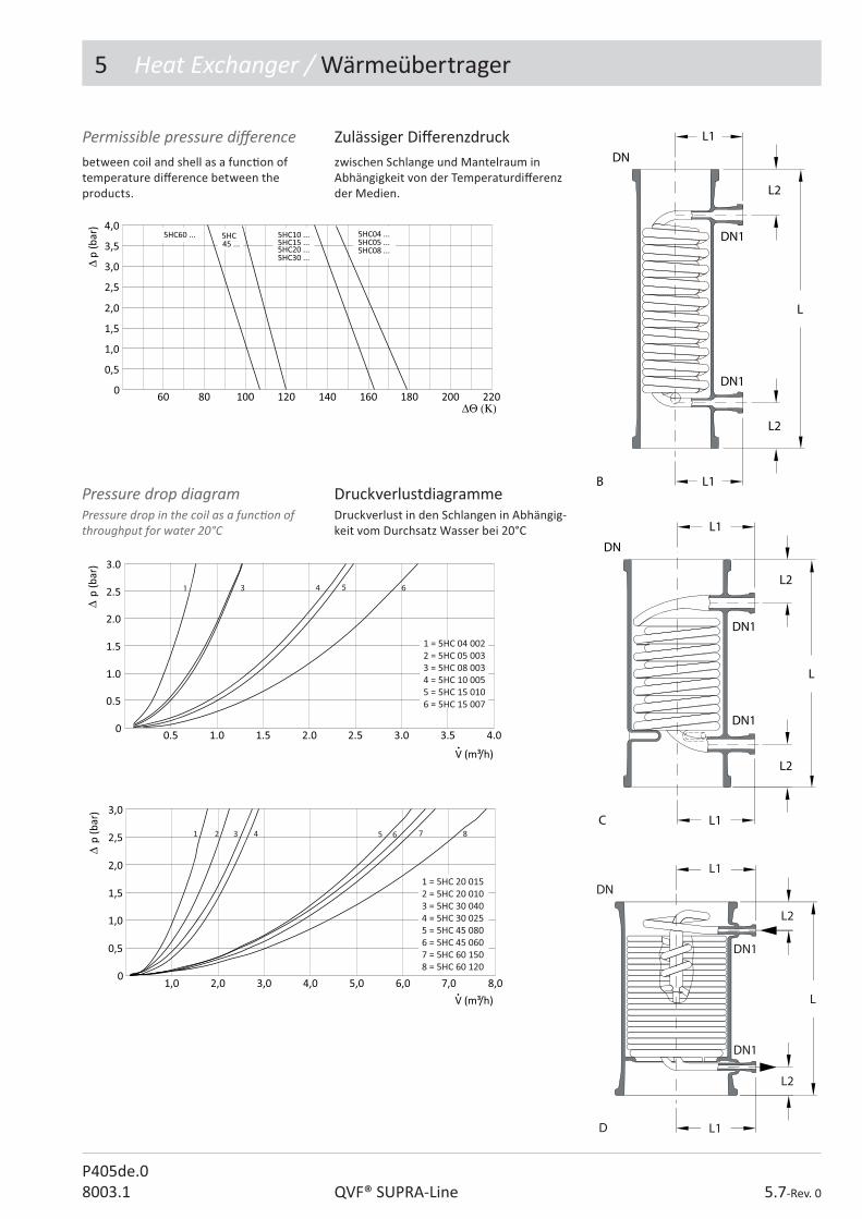
5 Heat Exchanger / Wärmeübertrager
5.7-Rev. 0QVF® SUPRA-LineP405de.08003.1
Zulässiger Di� erenzdruckzwischen Schlange und Mantelraum in Abhängigkeit von der Temperaturdi� erenz der Medien.
Permissible pressure di� erencebetween coil and shell as a func� on of temperature di� erence between the products.
DruckverlustdiagrammeDruckverlust in den Schlangen in Abhängig-keit vom Durchsatz Wasser bei 20°C
Pressure drop diagramPressure drop in the coil as a func� on of throughput for water 20°C
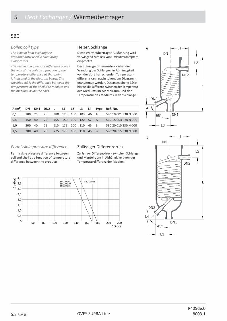
5 Heat Exchanger / Wärmeübertrager
5.8-Rev. 0 QVF® SUPRA-LineP405de.0
8003.1
Heizer, Schlange Diese Wärmeübertrager-Ausführung wird vorwiegend zum Bau von Umlaufverdampfern eingesetzt.
Der zulässige Di� erenzdruck über die Wandung der Schlangen in Abhängigkeit von der dort herrschenden Temperatur-di� erenz kann nachstehendem Diagramm entnommen werden. Das angegebene �[ ist hierbei die Di� erenz zwischen der Temperatur des Mediums im Mantelraum und der Temperatur des Mediums in der Schlange.
Boiler, coil typeThis type of heat exchanger is predominantly used in circulatory evaporators.The permissible pressure di� erence across the wall of the coils as a func� on of the temperature di� erence at that point is indicated in the diagram below. The speci� ed � is the di� erence between the temperature of the shell side medium and the medium inside the coils.
5BC
A (m²) DN DN1 DN2 L L1 L2 L3 L4 Type Ref.-No.
0,1 100 25 25 380 125 100 103 46 A 5BC 10 001 330 N 000
0,4 150 40 25 455 150 100 122 57 A 5BC 15 004 330 N 000
1,0 200 40 25 615 175 100 110 45 B 5BC 20 010 330 N 000
1,5 200 40 25 775 175 100 110 45 B 5BC 20 015 330 N 000
Zulässiger Di� erenzdruckZulässiger Di� erenzdruck zwischen Schlange und Mantelraum in Abhängigkeit von der Temperaturdi� erenz der Medien.
Permissible pressure di� erencePermissible pressure di� erence between coil and shell as a func� on of temperature di� erence between the products.

5 Heat Exchanger / Wärmeübertrager
5.9-Rev. 0QVF® SUPRA-LineP405de.08003.1
Ref.-No. Area / Flächem²
V Coil / V Schlangel
V shell / V Mantell
Steam pressure/ Dampfdruckbar g
Water evaporated /Wasserverdampfungkg/h
5BC 10 001 330 N 000 0,2 0,25 2,3 2 2,7
3 3,3
5BC 15 004 330 N 000 0,3 1,0 4,7 2 12,5
3 16,5
5BC 20 010 330 N 000 0,3 2,1 14 2 20
3 24
5BC 20 015 330 N 000 1,5 3,2 15 2 29
3 37
Technische Daten / Leistungs-datenZur Auslegung können folgende geometrische Daten verwendet werden.
Zur überschlägigen Bes� mmung der Verdampfungsleistung kann der Wärme-durchgangskoe� zient bei allen Größen und einem Heizdampfdruck von 3,0 bar mit 400 W/m²K angenommen werden. Bei niedrigeren Drücken verändert sich dieser Wert geringfügig. Daraus ergeben sich für die Verdampfung von Wasser mit einer Eintri� stemperatur von 100 °C (ein kalter Zu� uss reduziert die Werte auf ca. 80%) und bei Atmosphärendruck folgende Leistungen:
Technical data / performance dataFor the calcula� on use the following geometrical data. For approximate calcula� on of the evapora� on rate the overall heat transfer coe� cient in all sizes can be considered on average as 400 W/m²K with a steam pressure in the coils of 3.0 bar g. This � gure declines marginally at lower pressures. The table below shows � gures calculated on this basis for the evapora� on of water with an inlet temperature of 100 °C and at atmospheric pressure (if the feed is cold, the performance of the boiler will be only about 80% of the � gures below):
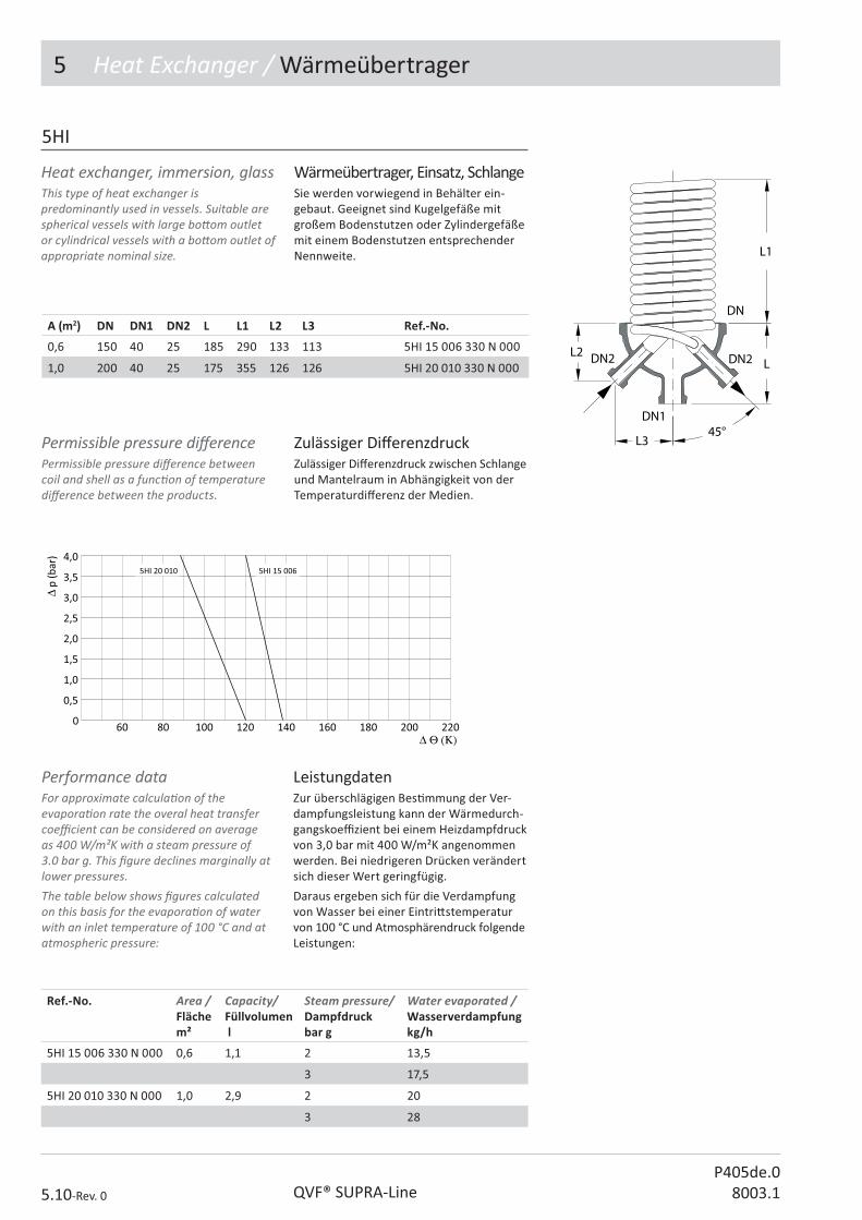
5 Heat Exchanger / Wärmeübertrager
5.10-Rev. 0 QVF® SUPRA-LineP405de.0
8003.1
Wärmeübertrager, Einsatz, SchlangeSie werden vorwiegend in Behälter ein-gebaut. Geeignet sind Kugelgefäße mit großem Bodenstutzen oder Zylindergefäße mit einem Bodenstutzen entsprechender Nennweite.
Heat exchanger, immersion, glassThis type of heat exchanger is predominantly used in vessels. Suitable are spherical vessels with large bo� om outlet or cylindrical vessels with a bo� om outlet of appropriate nominal size.
5HI
A (m2) DN DN1 DN2 L L1 L2 L3 Ref.-No.
0,6 150 40 25 185 290 133 113 5HI 15 006 330 N 000
1,0 200 40 25 175 355 126 126 5HI 20 010 330 N 000
LeistungdatenZur überschlägigen Bes� mmung der Ver-dampfungsleistung kann der Wärmedurch-gangskoe� zient bei einem Heizdampfdruck von 3,0 bar mit 400 W/m²K angenommen werden. Bei niedrigeren Drücken verändert sich dieser Wert geringfügig.
Daraus ergeben sich für die Verdampfung von Wasser bei einer Eintri� stemperatur von 100 °C und Atmosphärendruck folgende Leistungen:
Performance dataFor approximate calcula� on of the evapora� on rate the overal heat transfer coe� cient can be considered on average as 400 W/m²K with a steam pressure of 3.0 bar g. This � gure declines marginally at lower pressures.The table below shows � gures calculated on this basis for the evapora� on of water with an inlet temperature of 100 °C and at atmospheric pressure:
Ref.-No. Area / Flächem²
Capacity/ Füllvolumen l
Steam pressure/ Dampfdruckbar g
Water evaporated /Wasserverdampfungkg/h
5HI 15 006 330 N 000 0,6 1,1 2 13,5
3 17,5
5HI 20 010 330 N 000 1,0 2,9 2 20
3 28
Zulässiger Di� erenzdruckZulässiger Di� erenzdruck zwischen Schlange und Mantelraum in Abhängigkeit von der Temperaturdi� erenz der Medien.
Permissible pressure di� erencePermissible pressure di� erence between coil and shell as a func� on of temperature di� erence between the products.

5 Heat Exchanger / Wärmeübertrager
5.11-Rev. 0QVF® SUPRA-LineP405de.08003.1
FlüssigkeitskühlerDie Flüssigkeitskühler eignen sich bevor-zugt als Nachkühler für Des� llate und können z.B. unmi� elbar am Rück� usskopf einer Kolonne angeschlossen werden.
Cooler, liquidThese liquid coolers are used typically for the cooling of products from dis� lla� on columns and can be connected directly to the re� ux head of a column.
5CL
A (m²) DN DN1 DN2 L L1 L2 Ref.-No.
0,3 100 25 25 550 85 35 5CL 02 003 330 N 000
0,5 150 25 25 550 104 43 5CL 02 005 330 N 000
1,0 150 25 25 750 104 43 5CL 02 010 330 N 000
Technical data Technische Daten
Ref.-No. Area / Flächem²
V Coil / V Schlangel
V Shell / V Mantell
5CL 02 003 330 N 000 0,3 0,6 2,5
5CL 02 005 330 N 000 0,5 1,2 5,2
5CL 02 010 330 N 000 1,0 2,1 7,3
Zulässiger Di� erenzdruckzwischen Schlange und Mantelraum in Abhängigkeit von der Temperaturdi� erenz der Medien.
Permissible pressure di� erencebetween coil and shell as a func� on of temperature di� erence between the products in the two areas.

5 Heat Exchanger / Wärmeübertrager
5.12-Rev. 0 QVF® SUPRA-LineP405de.0
8003.1
Nachkondensator Diese Apparate werden vor Vakuumpumpen oder in Abgasleitungen eingesetzt, um die nach dem Hauptkondensator noch im Gasstrom be� ndlichen damp� örmigen Bestandteile niederzuschlagen.
Condenser, vent These items are installed before vacuum pumps or in vent gas lines to condense components in the gas stream a� er the main condenser.
5CV
A (m²) DN DN1 DN2 L L1 L2 Ref.-No.
0,6 100 25 15 800 100 125 5CV 02 006 330 N 000
0,6 100 50 15 800 100 125 5CV 05 006 330 N 000
Technical data Technische Daten
Ref.-No. Area / Flächem²
V Coil / V Schlangel
V Shell / V Mantell
5CV 02 006 330 N 000 0,6 0,9 3,4
5CV 05 006 330 N 000 0,6 0,9 3,6
DruckverlustdiagrammDruckverlust in den Schlangen in Abhängig-keit vom Durchsatz Wasser bei 20°C
Pressure drop diagramPressure drop in the coil as a func� on of throughput for water 20°C
Zulässiger Di� erenzdruckzwischen Schlange und Mantelraum in Abhängigkeit von der Temperaturdi� erenz der Medien.
Permissible pressure di� erencebetween coil and shell as a func� on of temperature di� erence between the products.

5 Heat Exchanger / Wärmeübertrager
5.13-Rev. 0QVF® SUPRA-LineP405de.08003.1
Adapter, Schlauch, 90°, 1.4581Adaptor, tube, 90°, 1.4581
DN Tube Øi / Schlauch Øi
L L1 Ref.-No.
15 13 50 10 5AT 01 000 013 N 000
25 20 70 15 5AT 02 000 020 N 000
50 42 90 26 5AT 05 000 042 N 000
5AT
Zum Lieferumfang der Metall-Schlauchan-schlüsse gehören Dichtung, Flanschring, Einlage, Schrauben und Zubehör für deren Anschluss an die entsprechenden Stutzen mit SUPRA-Flansch.
Metal hose connectors are supplied together with the � ange, insert, gasket and fastenings necessary to connec� he metal hose connector to the glass branch.

5 Heat Exchanger / Wärmeübertrager
5.14-Rev. 0 QVF® SUPRA-LineP405de.0
8003.1
5HT
Konstruk� ver Au$ auDer Rohrboden des QVF®-Wärmeübertragers besteht aus reinem PTFE. Die Innenrohre werden durch einteilige Keilringver-schraubungen ohne zusätzliche Dichtung abgedichtet. Die Abdichtung zum Mantel und zur Haube erfolgt über O-Ringe.
Die Innenrohre bestehen wahlweise aus Borosilicatglas 3.3 oder Siliciumcarbid (siehe Bestellschlüssel).
Folgende Materialien kommen je nach Typ zum Einsatz:
• Mantel: Glas/Stahl/andere• Innenrohre: Glas/SiC• Rohrboden + Verschraubung: PTFE• Stützpla� e: 1.4301• Hauben: Glas/1.4301
Sowohl die Stahl- als auch die Glashauben können mit Umlenksegmenten ausgerüstet werden, so dass eine 1- oder 3-gängige Fahrweise möglich ist (siehe Bestellschlüssel).
Der Mantel ist dreiteilig ausgeführt. Die Lage der Anschlussstutzen muss bei Auf-tragsvergabe festgelegt werden.
Die Umlenksegmente im Mantelraum be-stehen grundsätzlich aus PTFE und werden durch Glasdistanzstäbe gehalten.
Für den senkrechten Einbau können die Wärmeübertrager auf Wunsch mit einem Entleerungsven� l im Boden ausgerüstet werden. Diese Sonderform erfordert zu-sätzlich eine spezielle Halterung.
Heat exchanger, tube & shell Rohrbündel-Wärmeübertrager
Structural designThe tube sheet of the QVF® heat exchanger consists of pure PTFE. The internal tubes are sealed with single-piece tapered ring � � ngs without addi� onal sealing. The shell and header are sealed using O rings.The internal tubes are made of either borosilicate glass 3.3 or silicon carbide (see order key). The following materials are used, depend-ing on the type:• Shell: glass/steel/other• Internal tubes: glass/SiC• Tube plate+� � ng: PTFE• Suppor� ng plate: 1.4301• Hoods: glass/1.4301
Both the steel and glass headers can be equipped with segments so that a 1 or 3-pass running mode is possible (see order key). The shell is designed in three parts. The loca� on of the connec� on nozzles must be determined when ordering.The ba� es in the jacket area are made of PTFE and held through glass spacer rods.For ver� cal installa� on, the heat exchang-ers can be equipped with a drain valve in the tube sheet, if desired. This special form also requires a special holder.

5 Heat Exchanger / Wärmeübertrager
5.15-Rev. 0QVF® SUPRA-LineP405de.08003.1
AuslegungsdatenAlle wärmetechnischen Angaben beziehen sich auf die Außen� äche der Innenrohre. Die Innenrohre werden in festen Längen ver-wendet. Die unterschiedlichen Übertragungs-� ächen ergeben sich aus der Anzahl und Länge der Innenrohre. Gerechnet wurde mit der Länge zwischen den Rohrböden.
Die Klassi� zierung der Wärmeübertrager erfolgt nach Nenn� ächen.
Die maximale Temperaturdi� erenz zwischen den Räumen beträgt 130 K. Unabhängig vom angegebenen Temperaturbereich darf bei Borosilicatglaskomponenten die Schock-temperatur 120 °C nicht überschreiten.
Wärmeübertrager AnwendungenQVF®-Rohrbündel-Wärmeübertrager sind für typische Anwendungsfälle konzipiert, die zu den nachfolgend beschriebenen Typen geführt haben.
Detailierte Auslegungen können von uns ausgeführt werden. Sprechen Sie uns an.
Design dataAll heat-related speci� ca� ons refer to the outside surface of the internal tubes. The internal tubes are used in � xed lengths. The various transfer surfaces result from the number and length of the internal tubes. The length between the tube plates was used in the calcula� on. Classi� ca� on of the heat exchangers is made according to nominal heat transfer area. The maximum temperature di� erence accross the wall of the tube is 130 K. Regardless of the speci� ed temperature range, the shock temperature of 120°C must not be exceeded for borosilicate glass components.
Heat transfer applica� onsQVF® shell and tube heat exchangers are designed for typical applica� ons, as described below.We can carry out detailed layouts. Please connect us

5 Heat Exchanger / Wärmeübertrager
5.16-Rev. 0 QVF® SUPRA-LineP405de.0
8003.1
Flüssig/Flüssig WärmerückgewinnungZwei Produktströme werden mit op� maler Strömungsgeschwindigkeit gegeneinander geführt. Beide können korrosionsbeständige Materialien erfordern.
Liquid/liquid heat transferTwo product � ows are countercurrent with op� mal � ow velocity. Both sides have corrosion-resistant materials.
Type 1 Shell / Mantel Tubes / Innenrohre Header / Haube
Fluid / Medium Product /Produkt
Product /Produkt
Material / Material Glass / Glas Glass/SiC / Glas/SiC Glass / Glas
Working pressure bar g / Betriebsüberdruck bar g
-1/+1(2) -1/+3 -1/+3
Working temperature °C / Betriebstemperatur °C
-20/+150 -20/+150 -20/+150
Type 1

5 Heat Exchanger / Wärmeübertrager
5.17-Rev. 0QVF® SUPRA-LineP405de.08003.1
Kondensa� onBei Kondensa� onsprozessen ist im Allge-meinen die Kühlwasserseite nicht korrosiv. Für höhere Drücke wird der PTFE-Boden mit einer Edelstahlpla� e auf der Kühlwasser-seite verstärkt.
Condensa� onIn condensa� on processes, the cooling water side is generally non corrosive. For higher pressures, the PTFE tube sheet is reinforced with a stainless steel plate on the cooling water side.
Type 2 Shell / Mantel Tubes / Innenrohre Header / Haube
Fluid / Medium Product /Produkt
Service /Kühlmedium
Material / Material Glass / Glas Glass/SiC / Glas/SiC Steel / Stahl
Working pressure bar g / Betriebsüberdruck bar g
-1/+1(2) -1/+3 -1/+3
Working temperature °C / Betriebstemperatur °C
-20/+150 -20/+150 -20/+150
Type 3 Shell / Mantel Tubes / Innenrohre Header / Haube
Fluid / Medium Product /Produkt
Service /Kühlmedium
Material / Material Glass / Glas Glass/SiC / Glas/SiC Steel / Stahl
Working pressure bar g / Betriebsüberdruck bar g
-1/+1(2) -1/+6 -1/+6
Working temperature °C / Betriebstemperatur °C
-20/+150 -20/+150 -20/+150
Type 4 Shell / Mantel Tubes / Innenrohre Header / Haube
Fluid / Medium Service /Kühlmedium
Product /Produkt
Material / Material Steel / Stahl Glass/SiC / Glas/SiC Glass / Glas
Working pressure bar g / Betriebsüberdruck bar g
-1/+6 -1/+3 -1/+3
Working temperature °C / Betriebstemperatur °C
-20/+150 -20/+150 -20/+150
Type 2, Type 3, Type 4

5 Heat Exchanger / Wärmeübertrager
5.18-Rev. 0 QVF® SUPRA-LineP405de.0
8003.1
GMP-AnwendungBei diesem Typ steht die Trennung der beiden Betriebsräume durch eine Kammer im Vordergrund, so dass für die Medien keine Triebkra� für den Übertri� in den anderen Raum vorhanden ist.
Da die kontamina� onsfreie Trennung der Medien auch bei stark reagierenden Medien sicherheitstechnisch geboten ist, bieten wir den Doppelboden-Wärmeübertrager auch in korrosionsfester Ausführung an.
GMP applica� onFor this type, the separa� on of the two opera� ng spaces by a chamber is the important point, so that the media cannot crosscontaminate each other. No propulsion of the media is applied for movement into the other space.Since contamina� on-free media separa� on is required for safety reasons for strongly reac� ve media as well, we o� er the double-tube plate heat exchanger in corrosion-resistant design as well.
Type 5 Shell / Mantel Tubes / Innenrohre Header/Chamber / Haube/Kammer
Fluid / Medium Product /Produkt
Product /Produkt
Material / Material Glass / Glas Glass/SiC / Glas/SiC Glass / Glas
Working pressure bar g / Betriebsüberdruck bar g
-1/+1(2) -1/+3 -1/+3
Working temperature °C / Betriebstemperatur °C
-20/+150 -20/+150 -20/+150
Type 6 Shell / Mantel Tubes / Innenrohre Header/Chamber / Haube/Kammer
Fluid / Medium Product /Produkt
Service /Kühlmedium
Material / Material Glass / Glas Glass/SiC / Glas/SiC Steel / Stahl
Working pressure bar g / Betriebsüberdruck bar g
-1/+1(2) -1/+6 -1/+6
Working temperature °C / Betriebstemperatur °C
-20/+150 -20/+150 -20/+150
Type 5, Type 6

5 Heat Exchanger / Wärmeübertrager
5.19-Rev. 0QVF® SUPRA-LineP405de.08003.1
DN L Tubes /L Rohre(mm)
Tubes / Rohre (n)Type: 1,2,5,6 / 3,4
Type 1-4A (m²)
Type 5+6A (m²)
Type 1 bis 4
Ref.-No.
Type 5+6
Ref.-No.
150 1200 37/36 1,7 1,4 5HT 15 018 ??? N 000 5HT 15 014 ??? N 000
150 1480 37/36 2,2 1,8 5HT 15 022 ??? N 000 5HT 15 018 ??? N 000
150 1980 37/36 3,0 2,7 5HT 15 030 ??? N 000 5HT 15 027 ??? N 000
150 2480 37/36 3,8 3,5 5HT 15 038 ??? N 000 5HT 15 035 ??? N 000
150 2980 37/36 4,6 4,3 5HT 15 046 ??? N 000 5HT 15 043 ??? N 000
150 3480 37/36 5,4 5,1 5HT 15 054 ??? N 000 5HT 15 051 ??? N 000
150 4200 37/36 6,5 6,3 5HT 15 065 ??? N 000 5HT 15 063 ??? N 000
200 1200 61/59 2,9 2,3 5HT 20 030 ??? N 000 5HT 20 022 ??? N 000
200 1480 61/59 3,8 3,0 5HT 20 038 ??? N 000 5HT 20 030 ??? N 000
200 1980 61/59 5,0 4,4 5HT 20 050 ??? N 000 5HT 20 044 ??? N 000
200 2480 61/59 6,3 5,7 5HT 20 063 ??? N 000 5HT 20 057 ??? N 000
200 2980 61/59 7,5 7,0 5HT 20 075 ??? N 000 5HT 20 070 ??? N 000
200 3480 61/59 8,8 8,4 5HT 20 088 ??? N 000 5HT 20 084 ??? N 000
200 4200 61/59 11 10 5HT 20 110 ??? N 000 5HT 20 100 ??? N 000
300 1200 151/148 7,5 7,1 5HT 30 072 ??? N 000 5HT 30 057 ??? N 000
300 1480 151/148 9 7,5 5HT 30 090 ??? N 000 5HT 30 075 ??? N 000
300 1980 151/148 12 11 5HT 30 120 ??? N 000 5HT 30 110 ??? N 000
300 2480 151/148 15 14 5HT 30 150 ??? N 000 5HT 30 140 ??? N 000
300 2980 151/148 19 17 5HT 30 180 ??? N 000 5HT 30 170 ??? N 000
300 3480 151/148 22 21 5HT 30 220 ??? N 000 5HT 30 210 ??? N 000
300 4200 151/148 27 25 5HT 30 270 ??? N 000 5HT 30 250 ??? N 000
BestellnummernReference numbers
Design key 2 Type and material
Ausführungsschlüssel 2 Typ und Material
Code
Type 1 / Typ 1 1
Type 2 / Typ 2 2
Type 3 / Typ 3 3
Type 4 / Typ 4 4
Type 5 / Typ 5 5
Type 6 / Typ 6 6
1 pass / 1-zügig 1
3 passes / 3-zügig 3
Glass tubes horizontal / Glas Innenrohre waagerecht 1
SiC tubes horizontal / SiC Innenrohre waagerecht 2
Glass tubes ver� cal / Glas Innenrohre senkrecht 3
SiC tubes ver� cal / SiC Innenrohre senkrecht 4

5 Heat Exchanger / Wärmeübertrager
5.20-Rev. 0 QVF® SUPRA-LineP405de.0
8003.1
Installa� on/EinbaumaßeDer Wärmeübertrager ist für den waage-rechten Einbau vorgesehen. Er wird auf den mitgelieferten Tragsä� eln installiert, wobei ein Fest- und ein Loslager vorzusehen sind.
Der Anschluss von Produkt- und Serviceseite muss spannungsfrei erfolgen. Dies kann auf der Produktseite durch Faltenbälge und auf der Serviceseite alterna� v durch Schläuche geschehen.
Druckstöße sind zu vermeiden.
Installa� on/dimensions The heat exchanger is intended for horizontal installa� on. It is installed on the supplied support saddles, whereby both a � xed and a loose point are to be provided.Both the product and service side must be connected without tension. This can be achieved on the product side with bellows and on the service side alterna� vely with hoses.Pressure shocks must be avoided.
DN A (m²)Type 1-4
A (m²)Type 5+6
L (ca.) H DN1 DN2 DN3
150 1,7 1,4 1600 300 40/50 100 50
150 2,2 1,8 1900
150 3,0 2,7 2400
150 3,8 3,5 2900
150 4,6 4,3 3400
150 5,4 5,1 3900
150 6,2 6,3 4600
200 2,9 2,3 1700 400 50/80 150 50
200 3,8 3,0 2000
200 5,0 4,4 2500
200 6,3 5,7 3000
200 7,5 7,0 3500
200 8,8 8,4 4000
200 11 10 4700
300 7,5 7,1 1800 500 80/100 200 50
300 9,0 7,5 2000
300 12 11 2500
300 15 14 3000
300 19 17 3500
300 22 21 4000
300 27 25 4800

5 Heat Exchanger / Wärmeübertrager
5.21-Rev. 0QVF® SUPRA-LineP405de.08003.1
LeistungsdatenZur überschlägigen Berechnung von Wärmeübertragungs� ächen kann für verschiedene Innenrohre von folgenden Richtwerten für die Wärmedurchgangszahlen ausgegangen werden:
Performance dataAn approximate calcula� on of heat transfer areas can be based on the following guide � gures for di� erent materials of the inner tubes.
Applica� on / Anwendung
Fluid / Medium k-value / k-Wert W/m²K
Glass / Glas SiC
Liquid/Liquid /Flüssig/Flüssig
Water - Wasser /Water - Wasser
330-560 650 - 1800
Water - Organics / Wasser - Lösemi� el
300 - 500 500 - 1400
Water - Heat transfer oil / Wasser - Wärmeträgeröl
220 - 400 400 - 800
Liquid/Gas /Flüssig/ Gas
Water - Air / Wasser - Lu�
15 - 90 15 - 90
Liquid/Vapour /Flüssig/ Dampf
Water - Water /Wasser - Wasser
520 - 640 1400 - 3100
Water - Organics / Wasser - Lösemi� el
400 - 580 900 - 2100
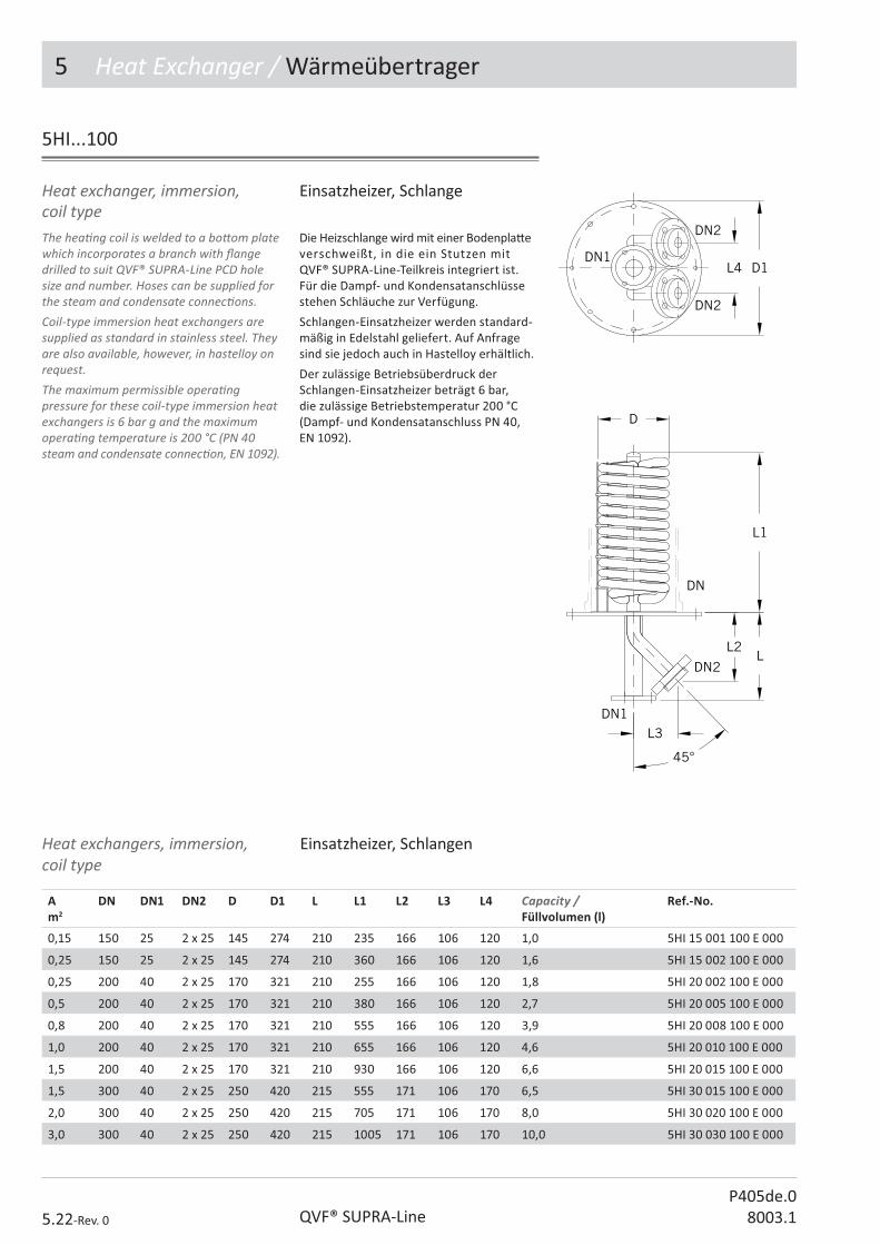
5 Heat Exchanger / Wärmeübertrager
5.22-Rev. 0 QVF® SUPRA-LineP405de.0
8003.1
Einsatzheizer, Schlange Die Heizschlange wird mit einer Bodenpla� e verschweißt, in die ein Stutzen mit QVF® SUPRA-Line-Teilkreis integriert ist. Für die Dampf- und Kondensatanschlüsse stehen Schläuche zur Verfügung.
Schlangen-Einsatzheizer werden standard-mäßig in Edelstahl geliefert. Auf Anfrage sind sie jedoch auch in Hastelloy erhältlich.
Der zulässige Betriebsüberdruck der Schlangen-Einsatzheizer beträgt 6 bar, die zulässige Betriebstemperatur 200 °C (Dampf- und Kondensatanschluss PN 40, EN 1092).
Heat exchanger, immersion, coil typeThe hea� ng coil is welded to a bo� om plate which incorporates a branch with � ange drilled to suit QVF® SUPRA-Line PCD hole size and number. Hoses can be supplied for the steam and condensate connec� ons. Coil-type immersion heat exchangers are supplied as standard in stainless steel. They are also available, however, in hastelloy on request.The maximum permissible opera� ng pressure for these coil-type immersion heat exchangers is 6 bar g and the maximum opera� ng temperature is 200 °C (PN 40 steam and condensate connec� on, EN 1092).
5HI...100
Einsatzheizer, SchlangenHeat exchangers, immersion,coil type
A m2
DN DN1 DN2 D D1 L L1 L2 L3 L4 Capacity /Füllvolumen (l)
Ref.-No.
0,15 150 25 2 x 25 145 274 210 235 166 106 120 1,0 5HI 15 001 100 E 000
0,25 150 25 2 x 25 145 274 210 360 166 106 120 1,6 5HI 15 002 100 E 000
0,25 200 40 2 x 25 170 321 210 255 166 106 120 1,8 5HI 20 002 100 E 000
0,5 200 40 2 x 25 170 321 210 380 166 106 120 2,7 5HI 20 005 100 E 000
0,8 200 40 2 x 25 170 321 210 555 166 106 120 3,9 5HI 20 008 100 E 000
1,0 200 40 2 x 25 170 321 210 655 166 106 120 4,6 5HI 20 010 100 E 000
1,5 200 40 2 x 25 170 321 210 930 166 106 120 6,6 5HI 20 015 100 E 000
1,5 300 40 2 x 25 250 420 215 555 171 106 170 6,5 5HI 30 015 100 E 000
2,0 300 40 2 x 25 250 420 215 705 171 106 170 8,0 5HI 30 020 100 E 000
3,0 300 40 2 x 25 250 420 215 1005 171 106 170 10,0 5HI 30 030 100 E 000

5 Heat Exchanger / Wärmeübertrager
5.23-Rev. 0QVF® SUPRA-LineP405de.08003.1
Heat exchanger, immersion, ring typeThese items are recommended for the use in spherical vessels as they provide a high heat transfer and evapora� on rate in conjunc� on with a central turbine s� rrer. The forced circula� on across the heat transfer surface results in evapora� on down to a very low residual volume. Circular ring immersion heat exchangers are supplied as standard in stainless steel. Other materials are also available.The maximum permissible opera� ng pressure for circular ring immersion heat exchangers is 6 bar g and the maximum opera� ng temperature is 200 °C (PN 40 steam and condensate connec� on, EN 1092).
Wärmeübertrager, Einsatz, KreisringKreisringheizer werden bevorzugt in Kugelgefäße eingebaut und ergeben in Ver-bindung mit einem zentral angeordneten Propellerrührer hohe Wärmeübergangs-zahlen und Verdampferleistungen. Durch die erzwungene Umströmung der Wär-meübertragungs� äche kann bis zu einem sehr geringen Restvolumen eingedamp� werden.
Kreisring-Einsatzheizer werden standard-mäßig in Edelstahl geliefert. Auf Anfrage sind sie jedoch auch in anderen Werksto� en erhältlich.
Der zulässige Betriebsüberdruck der Kreisring-Einsatzheizer beträgt 6 bar, die zulässige Betriebstemperatur 200 °C (Dampf- und Kondensatanschluss PN 40, EN 1092).
A m2
DN DN1 DN2 D D1 L L1 L2 L3 L4 Capacity /Füllvolumen (l)
Ref.-No.
0,15 200 40 2 x 25 155 321 261 225 96 100 151 0,75 5HI 20 015 200 E 000
0,2 200 40 2 x 25 155 321 261 285 96 100 151 1,0 5HI 20 020 200 E 000
0,25 200 40 2 x 25 155 321 261 340 96 100 151 1,25 5HI 20 025 200 E 000
0,3 300 40 2 x 25 235 420 265 295 100 100 210 3,0 5HI 30 030 200 E 000
0,35 300 40 2 x 25 235 420 265 330 100 100 210 3,5 5HI 30 035 200 E 000
0,4 300 40 2 x 25 235 420 265 370 100 100 210 4,0 5HI 30 040 200 E 000
0,45 300 40 2 x 25 235 420 265 405 100 100 210 4,5 5HI 30 045 200 E 000
0,5 300 40 2 x 25 235 420 265 445 100 100 210 5,0 5HI 30 050 200 E 000
5HI...200

5 Heat Exchanger / Wärmeübertrager
5.24-Rev. 0 QVF® SUPRA-LineP405de.0
8003.1
Kerzen-Einsatzheizer sind in den Nenn-weiten DN 80 bis DN 600 und mit Wärme-übertragungs� ächen von 0,05 bis 8,5 m2 lieferbar.
Der Boden dieser Heizer ist als Dampf-verteiler und Kondensatsammler ausge-bildet. Ein durchgeschweißter Stutzen mit QVF® SUPRA-Line-Teilkreis dient als Produktanschluss. Für die Dampf- und Kondensatanschlüsse stehen Schläuche zur Verfügung.
Kerzen-Einsatzheizer werden standard-mäßig in Tantal geliefert. Auf Anfrage sind sie jedoch auch in anderen Werksto� en erhältlich.
Der zulässige Betriebsüberdruck der Kerzen-Einsatzheizer beträgt 10 bar, die zu-lässige Betriebstemperatur 210 °C (Dampf- und Kondensatanschluss‚ PN 40, EN 1092).
Bayonet immersion heat exchangers can be supplied in nominal sizes DN 80 to DN 600 with heat transfer areas from 0.05 to 8.5 m2.The base of these boilers is designed to act as a vapour distributor and condensate collector. A branch drilled to suit QVF® SUPRA-Line PCD hole size and number welded through the base serves as a product connec� on. Hoses can be supplied for the steam and condensate connec� ons .Bayonet immersion heat exchangers are supplied in tantalum as standard. Other materials are, however, also available.The maximum permissible opera� ng pressure for bayonet immersion heat exchangers is 10 bar g and the maximum opera� ng temperature is 210 °C (PN 40 steam and condensate connec� on, EN 1092).
5HI...300
Heat exchanger, immersion, bayonet type
Wärmeübertrager, Kerzen-Einsatzheizer

P406e.08003.1
������������� �������
2. Pipeline Components
3. Valves and Filters
4. Vessels
5. Heat Exchangers
6. COLUMN COMPONENTS
������������
8. Measurement and Control
9. Couplings
10. Structures and Supports
The Component System
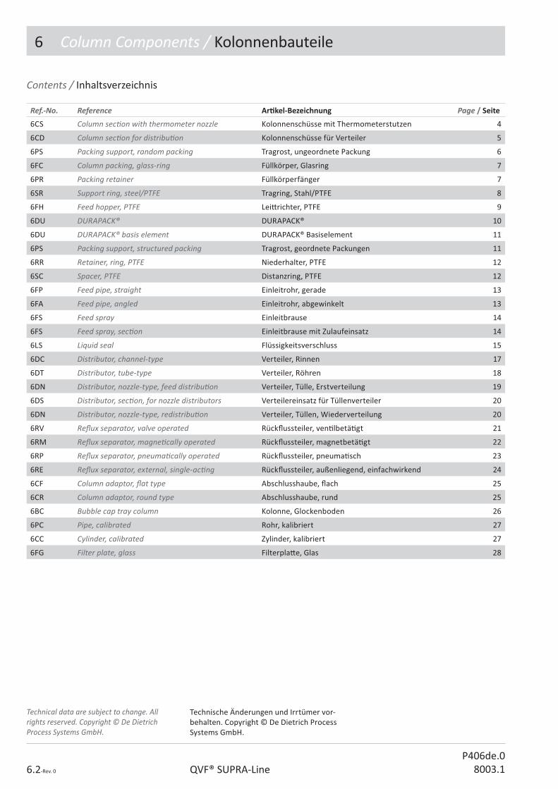
6 Column Components / Kolonnenbauteile
6.2-Rev. 0 QVF® SUPRA-LineP406de.0
8003.1
Contents / Inhaltsverzeichnis
Ref.-No. Reference Ar� kel-Bezeichnung Page / Seite
6CS Column sec� on with thermometer nozzle Kolonnenschüsse mit Thermometerstutzen 4
6CD Column sec� on for distribu� on Kolonnenschüsse für Verteiler 5
6PS Packing support, random packing Tragrost, ungeordnete Packung 6
6FC Column packing, glass-ring Füllkörper, Glasring 7
6PR Packing retainer Füllkörperfänger 7
6SR Support ring, steel/PTFE Tragring, Stahl/PTFE 8
6FH Feed hopper, PTFE Lei� richter, PTFE 9
6DU DURAPACK® DURAPACK® 10
6DU DURAPACK® basis element DURAPACK® Basiselement 11
6PS Packing support, structured packing Tragrost, geordnete Packungen 11
6RR Retainer, ring, PTFE Niederhalter, PTFE 12
6SC Spacer, PTFE Distanzring, PTFE 12
6FP Feed pipe, straight Einleitrohr, gerade 13
6FA Feed pipe, angled Einleitrohr, abgewinkelt 13
6FS Feed spray Einleitbrause 14
6FS Feed spray, sec� on Einleitbrause mit Zulaufeinsatz 14
6LS Liquid seal Flüssigkeitsverschluss 15
6DC Distributor, channel-type Verteiler, Rinnen 17
6DT Distributor, tube-type Verteiler, Röhren 18
6DN Distributor, nozzle-type, feed distribu� on Verteiler, Tülle, Erstverteilung 19
6DS Distributor, sec� on, for nozzle distributors Verteilereinsatz für Tüllenverteiler 20
6DN Distributor, nozzle-type, redistribu� on Verteiler, Tüllen, Wiederverteilung 20
6RV Re� ux separator, valve operated Rück� ussteiler, ven� lbetä� gt 21
6RM Re� ux separator, magne� cally operated Rück� ussteiler, magnetbetä� gt 22
6RP Re� ux separator, pneuma� cally operated Rück� ussteiler, pneuma� sch 23
6RE Re� ux separator, external, single-ac� ng Rück� ussteiler, außenliegend, einfachwirkend 24
6CF Column adaptor, � at type Abschlusshaube, � ach 25
6CR Column adaptor, round type Abschlusshaube, rund 25
6BC Bubble cap tray column Kolonne, Glockenboden 26
6PC Pipe, calibrated Rohr, kalibriert 27
6CC Cylinder, calibrated Zylinder, kalibriert 27
6FG Filter plate, glass Filterpla� e, Glas 28
Technical data are subject to change. All rights reserved. Copyright © De Dietrich Process Systems GmbH.
Technische Änderungen und Irrtümer vor-behalten. Copyright © De Dietrich Process Systems GmbH.

6 Column Components / Kolonnenbauteile
6.3-Rev. 0QVF® SUPRA-LineP406de.08003.1
Op� on key Sec� on 6 Variantenschlüssel Kapitel 6
N No op� on / Standard
D Dissipa� ve / ablei# ähig
L Sectrans / Sectrans
Ar� cle group / Ar� kelschlüssel
Nominal diameter key / Nennweitenschlüssel
Design key / Ausführungsschlüssel
Flange key / Flanschartenschlüssel
Op� on key / Variantenschlüssel
Sub item / Unterposi� on
6AA 00 000 000 A 000
QVF® SUPRA-Line Reference No.
Ar� cles of the QVF® SUPRA-Line component system are de� ned by a reference code of 15 characters. The code is led by the number of the catalogue sec� on and 2 le� ers linked to the English descrip� on.All other characters are used to specify the ar� cle in its group. The remaining posi� ons are � lled with “0”.In case a reference number has to be completed a “?” is shown. The right number is indicated in the op� on key table of the catalogue sec� on or the ar� cle group itself.Free space between the reference segments is not a part of the reference number it is only set to read the number easily.
QVF® SUPRA-Line Ar� kelnummern
Die Ar� kel des neuen QVF® SUPRA-Line Bauteileprogramms werden über eine 15-stellige Ar� kelnummer de� niert. Das 1. Segment - die Ar� kelgruppe - besteht aus der Kapitelzi� er und zwei Buchstaben die aus der englischen Bezeichnung des Ar� kels abgeleitet sind.
Alle weiteren Segmente dienen zur Di� eren-zierung der Ar� kel innerhalb einer Ar� kel-gruppe. Nicht benö� gte Stellen werden mit 0 aufgefüllt.
Zu ergänzende Stellen sind mit „?“ gekenn-zeichnet. Die wählbaren Bauteil-A� ribute sind ar� kelbezogen in einer Code-Tabelle aufgeführt.
Leerzeichen zwischen den einzelnen Segmenten dienen der besseren Lesbarkeit und sind kein Bestandteil der Ar� kelnummer.

6 Column Components / Kolonnenbauteile
6.4-Rev. 0 QVF® SUPRA-LineP406de.0
8003.1
6CS
Column sec� on with thermometer nozzle
Support trays are not in the scope of supply and have to be ordered separately.
Kolonnenschüsse mit Thermometer-stutzen
Tragroste gehören nicht zum Lieferumfang und sind separat zu bestellen
DN DN1 L L1 L2 H D Ref.-No.
80 25 1000 108 225 930 60 6CS 08 100 330 N 000
100 25 1000 122 225 930 76 6CS 10 100 330 N 000
150 25 1000 147 200 918 122 6CS 15 100 330 N 000
200 25 1000 171 200 918 166 6CS 20 100 330 N 000
200 25 1500 171 300 1418 166 6CS 20 150 330 N 000
300 25 1000 221 175 893 260 6CS 30 100 330 N 000
300 25 1500 221 275 1393 260 6CS 30 150 330 N 000
450 25 1500 299 250 1360 380 6CS 45 150 330 N 000
600 25 1500 377 255 1353 500 6CS 60 150 330 N 000
800 40 1500 562 300 1234 685 6CS 80 150 330 N 000
1000 40 1500 650 300 1234 855 6CS 11 150 330 N 000 1)
1) Reduced pressure 0.8 bar g 1) Reduzierter Betriebsüberdruck 0,8 bar
DN80 - DN600
DN800 - DN1000
Technical data Technische Daten
DN Afree / Afrei %
Bearing capacity / Tragfähigkeit N
80 61 170
100 64 250
150 75 500
200 81 900
300 84 1700
450 71 3300
600 69 5000
800 72 8000
1000 76 11000

6 Column Components / Kolonnenbauteile
6.5-Rev. 0QVF® SUPRA-LineP406de.08003.1
Column sec� on for distribu� on
They have three extra side branches with an o� set at 120° from each other so that a nozzle type distributor can be � � ed to redistribute the liquid. The distributor can be adjusted by means of ball and socket connec� ons.
Kolonnenschüsse für Verteiler
6CD
DN DN1 DN2 D L H L1 L2 L3 L4 Ref.-No.
300 25 40 260 1500 1228 221 275 125 226 6CD 30 150 330 N 000
450 25 40 380 1500 1155 299 250 135 308 6CD 45 150 330 N 000
600 25 40 500 1500 1098 377 255 175 385 6CD 60 150 330 N 000
Für den Einbau eines Tüllenverteilers zur Wiederverteilung der Flüssigkeit sind drei zusätzliche um 120° versetzte Stutzen vorgesehen.
Zur Jus� erung des Verteilerbodens werden Kugel/Pfanne-Verbindungen verwendet.

6 Column Components / Kolonnenbauteile
6.6-Rev. 0 QVF® SUPRA-LineP406de.0
8003.1
Please note the load bearing capacity of the packing support and the minimum size of packing to be used. The free cross sec� on takes into account the support ring of the column sec� on.The PTFE ring on which the grid is seated is in the scope of supply.
Packing support, random packing
Beachten Sie die Tragkra� des Rostes und die minimale Füllkörpergröße. Der freie Querschni� berücksich� gt den Au� agering der Kolonne.
Der unter dem Tragrost anzuordnende PTFE-Ring gehört zum Lieferumfang.
Tragrost, ungeordnete Packung
6PS...100
DN L L1 D E H Type Ref.-No.
80 68 52 - 10 13 A 6PS 08 100 000 N 000
100 87 58 - 12 13 A 6PS 10 100 000 N 000
150 138 113 - 13 21 A 6PS 15 100 000 N 000
200 185 166 - 15 21 A 6PS 20 100 000 N 000
300 293 261 - 15 21 A 6PS 30 100 000 N 000
450 - - 440 33 66 B 6PS 45 100 000 N 000
600 - - 590 33 91 B 6PS 60 100 000 N 000
800 - - 790 39 136 B 6PS 80 100 000 N 000
1000 - - 968 39 156 B 6PS 11 100 000 N 000
Technical data Technische Daten
DN Afree / Afrei
%
Bearing capacity /Tragfähigkeit N
Minimum size 6FC... / Mindestgröße 6FC
80 72 150 6FC 00 008 ...
100 78 200 6FC 00 015 ...
150 68 450 6FC 00 015 ...
200 69 800 6FC 00 020 ...
300 84 990 6FC 00 025 ...
450 79 3050 6FC 00 050 ...
600 79 3950 6FC 00 050 ...
800 81 10500 6FC 00 050 ...
1000 82 12500 6FC 00 050 ...
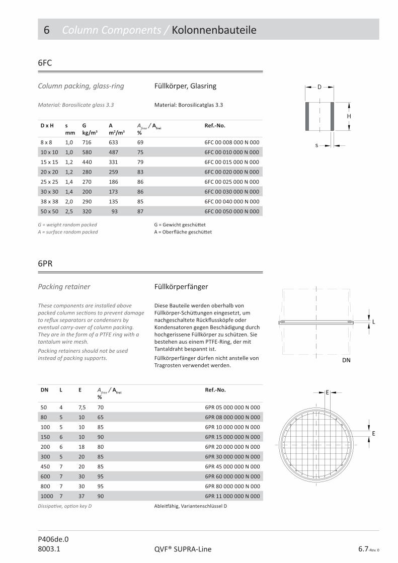
6 Column Components / Kolonnenbauteile
6.7-Rev. 0QVF® SUPRA-LineP406de.08003.1
Material: Borosilicate glass 3.3
Column packing, glass-ring
Material: Borosilicatglas 3.3
Füllkörper, Glasring
6FC
D x H smm
Gkg/m3
Am2/m3
Afree / Afrei %
Ref.-No.
8 x 8 1,0 716 633 69 6FC 00 008 000 N 000
10 x 10 1,0 580 487 75 6FC 00 010 000 N 000
15 x 15 1,2 440 331 79 6FC 00 015 000 N 000
20 x 20 1,2 280 259 83 6FC 00 020 000 N 000
25 x 25 1,4 270 186 86 6FC 00 025 000 N 000
30 x 30 1,4 200 173 86 6FC 00 030 000 N 000
38 x 38 2,0 290 135 85 6FC 00 040 000 N 000
50 x 50 2,5 320 93 87 6FC 00 050 000 N 000
G = weight random packedA = surface random packed
G = Gewicht geschü� etA = Ober� äche geschü� et
These components are installed above packed column sec� ons to prevent damage to re� ux separators or condensers by eventual carry-over of column packing. They are in the form of a PTFE ring with a tantalum wire mesh.Packing retainers should not be used instead of packing supports.
Packing retainer
Diese Bauteile werden oberhalb von Füllkörper-Schü� ungen eingesetzt, um nachgeschaltete Rück� ussköpfe oder Kondensatoren gegen Beschädigung durch hochgerissene Füllkörper zu schützen. Sie bestehen aus einem PTFE-Ring, der mit Tantaldraht bespannt ist.
Füllkörperfänger dürfen nicht anstelle von Tragrosten verwendet werden.
Füllkörperfänger
6PR
DN L E Afree / Afrei %
Ref.-No.
50 4 7,5 70 6PR 05 000 000 N 000
80 5 10 65 6PR 08 000 000 N 000
100 5 10 85 6PR 10 000 000 N 000
150 6 10 90 6PR 15 000 000 N 000
200 6 18 80 6PR 20 000 000 N 000
300 5 20 85 6PR 30 000 000 N 000
450 7 20 85 6PR 45 000 000 N 000
600 7 30 95 6PR 60 000 000 N 000
800 7 30 95 6PR 80 000 000 N 000
1000 7 37 90 6PR 11 000 000 N 000
Dissipa� ve, op� on key D Ablei# ähig, Variantenschlüssel D
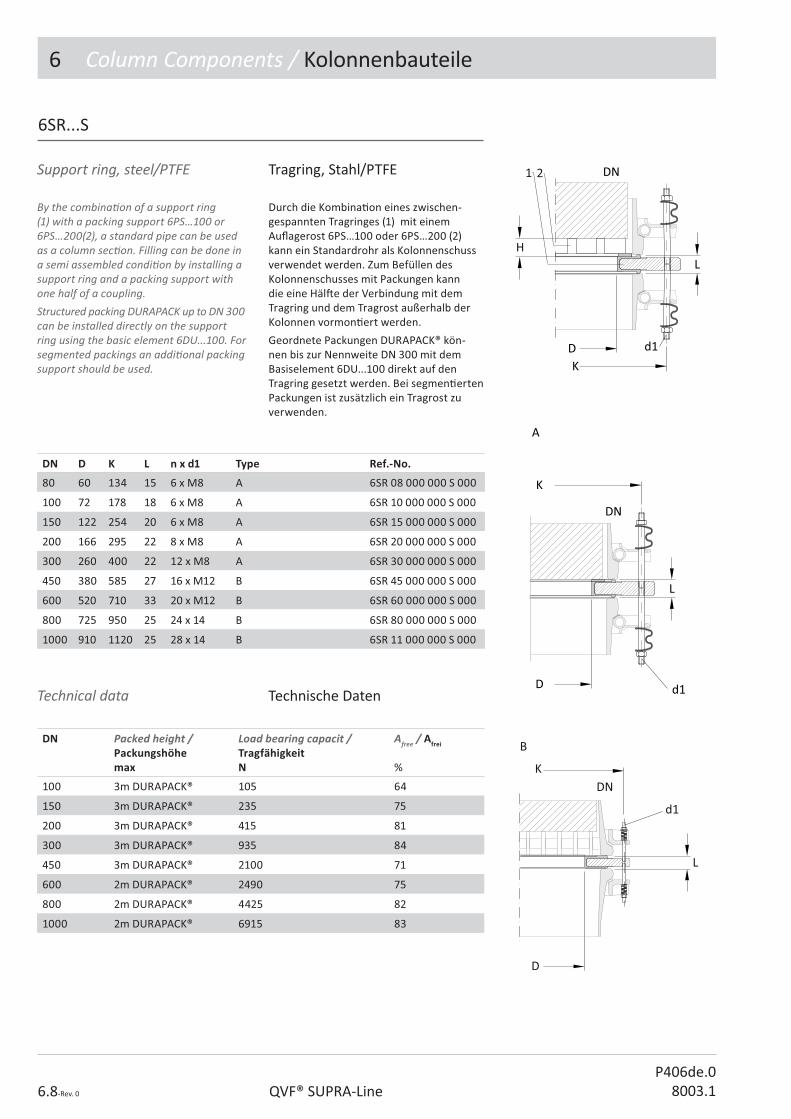
6 Column Components / Kolonnenbauteile
6.8-Rev. 0 QVF® SUPRA-LineP406de.0
8003.1
Support ring, steel/PTFE Tragring, Stahl/PTFE
6SR...S
DN D K L n x d1 Type Ref.-No.
80 60 134 15 6 x M8 A 6SR 08 000 000 S 000
100 72 178 18 6 x M8 A 6SR 10 000 000 S 000
150 122 254 20 6 x M8 A 6SR 15 000 000 S 000
200 166 295 22 8 x M8 A 6SR 20 000 000 S 000
300 260 400 22 12 x M8 A 6SR 30 000 000 S 000
450 380 585 27 16 x M12 B 6SR 45 000 000 S 000
600 520 710 33 20 x M12 B 6SR 60 000 000 S 000
800 725 950 25 24 x 14 B 6SR 80 000 000 S 000
1000 910 1120 25 28 x 14 B 6SR 11 000 000 S 000
DN Packed height /Packungshöhemax
Load bearing capacit /Tragfähigkeit N
Afree / Afrei
%
100 3m DURAPACK® 105 64
150 3m DURAPACK® 235 75
200 3m DURAPACK® 415 81
300 3m DURAPACK® 935 84
450 3m DURAPACK® 2100 71
600 2m DURAPACK® 2490 75
800 2m DURAPACK® 4425 82
1000 2m DURAPACK® 6915 83
Technical data Technische Daten
By the combina� on of a support ring (1) with a packing support 6PS…100 or 6PS…200(2), a standard pipe can be used as a column sec� on. Filling can be done in a semi assembled condi� on by installing a support ring and a packing support with one half of a coupling.Structured packing DURAPACK up to DN 300 can be installed directly on the support ring using the basic element 6DU...100. For segmented packings an addi� onal packing support should be used.
Durch die Kombina� on eines zwischen-gespannten Tragringes (1) mit einem Au� agerost 6PS…100 oder 6PS…200 (2) kann ein Standardrohr als Kolonnenschuss verwendet werden. Zum Befüllen des Kolonnenschusses mit Packungen kann die eine Häl� e der Verbindung mit dem Tragring und dem Tragrost außerhalb der Kolonnen vormon� ert werden.
Geordnete Packungen DURAPACK® kön-nen bis zur Nennweite DN 300 mit dem Basiselement 6DU...100 direkt auf den Tragring gesetzt werden. Bei segmen� erten Packungen ist zusätzlich ein Tragrost zu verwenden.
B
K
d1
L
D
DN

6 Column Components / Kolonnenbauteile
6.9-Rev. 0QVF® SUPRA-LineP406de.08003.1
Feed hopper, PTFE
Lei� richter dienen gleichzei� g als Rand-abweiser und vereinfachte Sammler. Sie werden oberhalb von Wiederverteilern und Aufgabeverteilern eingesetzt. Ihr innerer Durchmesser ist auf die Tüllenverteiler abges� mmt. Eine zusätzliche Dichtung ist nicht erforderlich.
Kolonnenschüsse der Nennweiten DN 800 und DN 1000 verfügen über einen integrierten Lei� richter.
Lei� richter, PTFE
The redistributors act as simple liquid collectors and direct the liquid away from the column wall. They are therefore installed above redistributors and feed distributors. Their inside diameter is designed to match nozzle type distributors. No addi� onal gasket is necessary.Column sec� ons DN 800 and DN 1000 have an integrated redistributor.
DN D H Afree / Afrei%
Ref.-No.
50 35 10 54 6FH 05 000 000 N 000
80 55 10 54 6FH 08 000 000 N 000
100 70 15 58 6FH 10 000 000 N 000
150 105 20 57 6FH 15 000 000 N 000
200 132 30 54 6FH 20 000 000 N 000
300 216 30 62 6FH 30 000 000 N 000
450 336 30 66 6FH 45 000 000 N 000
600 452 30 64 6FH 60 000 000 N 000
6FH
Dissipa� v, op� on key D Ablei# ähig, Variantenschlüssel D
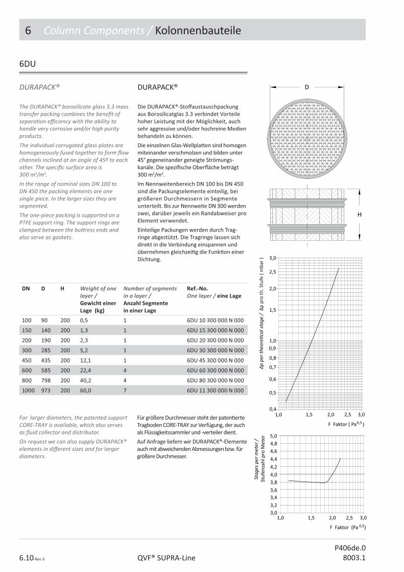
6 Column Components / Kolonnenbauteile
6.10-Rev. 0 QVF® SUPRA-LineP406de.0
8003.1
6DU
DURAPACK® DURAPACK®
The DURAPACK® borosilicate glass 3.3 mass transfer packing combines the bene� t of separa� on e� ciency with the ability to handle very corrosive and/or high purity products. The individual corrugated glass plates are homogeneously fused together to form � ow channels inclined at an angle of 45º to each other. The speci� c surface area is 300 m2/m3. In the range of nominal sizes DN 100 to DN 450 the packing elements are one single piece. In the larger sizes they are segmented. The one-piece packing is supported on a PTFE support ring. The support rings are clamped between the bu� ress ends and also serve as gaskets.
Die DURAPACK®-Sto� austauschpackung aus Borosilicatglas 3.3 verbindet Vorteile hoher Leistung mit der Möglichkeit, auch sehr aggressive und/oder hochreine Medien behandeln zu können.
Die einzelnen Glas-Wellpla� en sind homogen miteinander verschmolzen und bilden unter 45° gegeneinander geneigte Strömungs-kanäle. Die spezi� sche Ober� äche beträgt 300 m2/m3.
Im Nennweitenbereich DN 100 bis DN 450 sind die Packungselemente einteilig, bei größeren Durchmessern in Segmente unterteilt. Bis zur Nennweite DN 300 werden zwei, darüber jeweils ein Randabweiser pro Element verwendet.
Einteilige Packungen werden durch Trag-ringe abgestützt. Die Tragringe lassen sich direkt in die Verbindung einspannen und übernehmen gleichzei� g die Funk� on einer Dichtung.
DN D H Weight of one layer /Gewicht einer Lage (kg)
Number of segments in a layer /Anzahl Segmentein einer Lage
Ref.-No.One layer / eine Lage
100 90 200 0,5 1 6DU 10 300 000 N 000
150 140 200 1,3 1 6DU 15 300 000 N 000
200 190 200 2,3 1 6DU 20 300 000 N 000
300 285 200 5,2 1 6DU 30 300 000 N 000
450 435 200 12,1 1 6DU 45 300 000 N 000
600 585 200 22,4 4 6DU 60 300 000 N 000
800 798 200 40,2 4 6DU 80 300 000 N 000
1000 973 200 60,0 7 6DU 11 300 000 N 000
For larger diameters, the patented support CORE-TRAY is available, which also serves as � uid collector and distributor.On request we can also supply DURAPACK® elements in di� erent sizes and for larger diameters.
Für größere Durchmesser steht der paten� erte Tragboden CORE-TRAY zur Verfügung, der auch als Flüssigkeitssammler und -verteiler dient.
Auf Anfrage liefern wir DURAPACK®-Elemente auch mit abweichenden Abmessungen bzw. für größere Durchmesser.

6 Column Components / Kolonnenbauteile
6.11-Rev. 0QVF® SUPRA-LineP406de.08003.1
DURAPACK basis element DURAPACK Basiselement
6DU...100
Das DURAPACK® Basiselement kann mit der geschli� enen Seite und dem PTFE-Zentrier-ring direkt auf den Tragring 6SR aufgesetzt werden. Die darauf aufgesetzte Anzahl von DURAPACK-Elemeten richtet sich nach der Tragkra� des jeweiligen Tragringes.
The DURAPACK® basis element with a ground foot an a PTFE centring ring can be installed directly on the support ring 6SR. The number of addi� onal DURAPACK elements is restricted by the load bearing capacity of the support ring.
With all segmented, structured packing it is necessary to use extra packing supports on top of the support rings. These are made in a combina� on of borosilicate glass 3.3 and PTFE.
Packing support, structured packing
Bei allen segmen� erten, geordneten Packungen sind oberhalb der Tragringe zu-sätzlich Tragroste einzusetzen. Sie werden in der Werksto ̂ ombina� on Borosilicat-glas 3.3/PTFE gefer� gt.
Tragrost, geordnete Packungen
6PS...200
DN D L E E1 Afree / Afrei
%
Loard bearing / TragfähigkeitN
Ref.-No.
450 440 102 90 90 90 5300 6PS 45 200 000 N 000
600 592 102 140 90 86 3600 6PS 60 200 000 N 000
800 798 125 85 85 84 6000 6PS 80 200 000 N 000
1000 973 125 85 85 82 8000 6PS 11 200 000 N 000
L
DN
E1
E
D
DN D Ref.-No.
100 99 6DU 10 300 100 N 000
150 150 6DU 15 300 100 N 000
200 201 6DU 20 300 100 N 000
300 298 6DU 30 300 100 N 000
450 - without centering ring / ohne Zentriering 6DU 45 300 100 N 000
600 - without centering ring / ohne Zentriering 6DU 60 300 100 N 000
800 - without centering ring / ohne Zentriering 6DU 80 300 100 N 000
1000 - without centering ring / ohne Zentriering 6DU 11 300 100 N 000 D
H

6 Column Components / Kolonnenbauteile
6.12-Rev. 0 QVF® SUPRA-LineP406de.0
8003.1
Spacer, PTFE
The distance between DURAPACK® and the retainer should be � lled with one or more spacer rings made from PTFE.
Der Abstand zwischen Packung und Niederhalter wird mit einem oder mehreren Distanzringen aus PTFE ausgefüllt.
Distanzring, PTFE
6SC
DN D d1 H Afree / Afrei%
Ref.-No.
100 96 80 2 64 6SC 10 002 000 N 000
100 96 80 5 64 6SC 10 005 000 N 000
150 145 130 2 75 6SC 15 002 000 N 000
150 145 130 5 75 6SC 15 005 000 N 000
200 195 180 2 81 6SC 20 002 000 N 000
200 195 180 5 81 6SC 20 005 000 N 000
300 291 275 2 84 6SC 30 002 000 N 000
300 291 275 5 84 6SC 30 005 000 N 000
450 440 380 2 71 6SC 45 002 000 N 000
450 440 380 5 71 6SC 45 005 000 N 000
600 592 520 2 75 6SC 60 002 000 N 000
600 592 520 5 75 6SC 60 005 000 N 000
800 798 725 5 82 6SC 80 005 000 N 000
800 798 725 8 82 6SC 80 008 000 N 000
1000 973 910 5 83 6SC 11 005 000 N 000
1000 973 910 8 83 6SC 11 008 000 N 000
To avoid rela� ve movement o� he packing, a retainer has to be used between the upper coupling. For the nominal bores DN 800 and DN 1000 a support ring acts as an retainer.
Retainer, ring, PTFE
Am oberen Ende einer DURAPACK® Packung ist ein Niederhalter einzusetzen, um mögliche Rela� vbewegungen der Packung zur Kolonnen verhindern. Bei den Nennweiten DN 800 und DN 1000 werden Tragringe als Niederhalter eingesetzt
Niederhalter, PTFE
6RR
DN D L Afree / Afrei%
Ref.-No.
100 72 12 64 6RR 10 000 000 N 000
150 122 14 75 6RR 15 000 000 N 000
200 166 15 81 6RR 20 000 000 N 000
300 260 20 84 6RR 30 000 000 N 000
450 380 15 71 6RR 45 000 000 N 000
600 520 15 75 6RR 60 000 000 N 000

6 Column Components / Kolonnenbauteile
6.13-Rev. 0QVF® SUPRA-LineP406de.08003.1
Feed pipe, straight Einleitrohr, gerade
6FP
DN* DN1 DN2 L L1 Ref.-No.
80 40 25 100 100 6FP 08 004 330 N 000
80 50 25 100 115 6FP 08 005 330 N 000
100 40 25 100 125 6FP 10 004 330 N 000
100 50 25 100 125 6FP 10 005 330 N 000
150 40 25 100 150 6FP 15 004 330 N 000
150 50 25 100 150 6FP 15 005 330 N 000
200 40 25 100 175 6FP 20 004 330 N 000
200 50 25 100 175 6FP 20 005 330 N 000
300 40 25 100 225 6FP 30 004 330 N 000
300 50 25 100 225 6FP 30 005 330 N 000
450 80 40 125 325 6FP 45 008 330 N 000
600 150 50 200 450 6FP 60 015 330 N 000
Feed pipe, angled Einleitrohr, abgewinkelt
DN* DN1 DN2 L L1 d Ref.-No.
80 40 25 100 100 14,4 6FA 08 004 330 N 000
80 50 25 100 115 14,4 6FA 08 005 330 N 000
100 40 25 100 125 14,4 6FA 10 004 330 N 000
100 50 25 100 125 14,4 6FA 10 005 330 N 000
150 40 25 100 150 14,4 6FA 15 004 330 N 000
150 50 25 100 150 14,4 6FA 15 005 330 N 000
200 40 25 100 175 14,4 6FA 20 004 330 N 000
200 50 25 100 175 14,4 6FA 20 005 330 N 000
300 40 25 100 225 14,4 6FA 30 004 330 N 000
300 50 25 100 225 14,4 6FA 30 005 330 N 000
450 80 40 125 325 24,0 6FA 45 008 330 N 000
600 150 50 200 450 37,4 6FA 60 015 330 N 000
6FA
* DN ist der Kolonnendurchmesser* DN is the column diameter
* DN ist der Kolonnendurchmesser* DN is the column diameter

6 Column Components / Kolonnenbauteile
6.14-Rev. 0 QVF® SUPRA-LineP406de.0
8003.1
In the table below »DN« refers to the nominal size of the column.
Die Angabe »DN« in nachstehender Tabelle bezieht sich auf die Nennweite des Kolonnen-bauteils.
6FS...100
DN* DN1 DN2 L L1 L2 n x d Ref.-No.
450 150 50 200 500 250 40 x 3 6FS 45 100 330 N 000
600 150 50 200 650 400 60 x 3 6FS 60 100 330 N 000
Feed spray Einleitbrause
DN DN1 D L L1 n x d1 Ref.-No.
100 25 45 250 110 20 x 2 6FS 10 200 330 N 000
150 25 70 250 150 27 x 2 6FS 15 200 330 N 000
200 25 90 250 175 27 x 2 6FS 20 200 330 N 000
300 25 100 300 220 30 x 3 6FS 30 200 330 N 000
6FS...200
L1DN
Ld1
D
DN1
* DN ist der Kolonnendurchmesser* DN is the column diameter
DN2DN1
L2
n x d
DN2DN1
L L1
Feed spray, sec� on Einleitbrause mit Zulaufeinsatz

6 Column Components / Kolonnenbauteile
6.15-Rev. 0QVF® SUPRA-LineP406de.08003.1
Liquid seals are � � ed on the o� -take branch of automa� cally operated re� ux separators to prevent the � ow of vapours into the dis� llate line.
Liquid seal
Um den Eintri� von Dampf in die Des� llat-leitung beim Einsatz automa� sch betä� gter Rück� ussteiler zu verhindern, ist ein Flüssig-keitsverschluss erforderlich.
Flüssigkeitsverschluss
6LS
DN DN1 L L1 Ref.-No. Ref.-No.
25 25 160 205 6LS 02 000 123 N 000 6LS 02 000 333 N 000
40 25 315 305 6LS 04 000 123 N 000 6LS 04 000 333 N 000

6 Column Components / Kolonnenbauteile
6.16-Rev. 0 QVF® SUPRA-LineP406de.0
8003.1
The following criteria are important for the selec� on of the appropriate liquid distributor:• Process condi� ons such as pressure,
temperature and irriga� on density Bmax • Column diameter and type of packing • System proper� es where a dis� nc� on
should be made between clean (C=clean) and slightly soiled (S=soiled) product.
Liquid distributors can be selected from the table below on the basis of the nominal size of the column, irriga� on density and system proper� es.
Für die Auswahl des geeigneten Flüssig-keitsverteilers sind u.a. folgende Kriterien von Bedeutung:
• Prozessbedingungen wie Druck, Temperatur und Berieselungsdichte Bmax
• Kolonnendurchmesser und Art der Packung
• Systemeigenscha� en, wobei zwischen sauberen (C=clean) bzw. leicht verschmutzten (S=soiled) Systemen zu unterscheiden ist.
Nachstehende Tabelle ermöglicht die Vor-auswahl eines Flüssigkeitsverteilers nach der Nennweite DN der Kolonne, Berieselungs-dichte und Systemeigenscha� en.
6DC/DT/DN
Tube type distributorsRöhrenverteiler DN
Channel typedistributors Rinnenverteiler DN
Nozzle type distributors TüllenverteilerDN
System characteris� c Systemeigen-scha
Bmax approx. / Bmaxca.
m3/m2h
150 - - C 21
200 - - C 17
300 - - C 16
450 - - C 17
600 - - C 22
- 300 - C + S 12
- 450 - C + S 12
- 600 - C + S 10
- 800 - C + S 7,9
- 1000 - C + S 8,3
- - 200 C + S 43
- - 300 C + S 56
- - 450 C + S 79
- - 600 C + S 88
Liquid distributors general Flüssigkeitsverteiler, Allgemeines

6 Column Components / Kolonnenbauteile
6.17-Rev. 0QVF® SUPRA-LineP406de.08003.1
The liquid � ows through drilled holes aligned in a downward direc� on and also through over� ow pipes. The la� er start to work from 40% (stage 2) or 75 % (stage 3) respec� vely of the maximum irriga� on density onwards.On request, we can also supply Channel-type Distributors with an integrated collec� ng tray to be used as redistributors.
Distributor, channel-type
Der Rinnenverteiler mit gebohrten, nach unten gerichteten Löchern und zusätzlichen Überlaufröhrchen, die erst bei 40% (Stufe 2) bzw. 75% (Stufe 3) der maximalen Beriese-lungsdichte wirksam werden, bilden eine komple� e Einheit aus Borosilicatglas 3.3.
Auf Anfrage liefern wir Rinnenverteiler auch mit einem integrierten Sammler für den Einsatz als Wiederverteiler.
Verteiler, Rinnen
6DC
DN DN1 L L1 L2 n x d Type Ref.-No.
300 25 400 175 275 14 x 11 A 6DC 30 000 330 N 000
450 25 550 200 350 28 x 11 A 6DC 45 000 330 N 000
600 50 600 225 450 54 x 11 B 6DC 60 000 330 N 000
800 50 700 350 775 86 x 11 B 6DC 80 000 330 N 000
1000 50 700 350 850 130 x 11 B 6DC 11 000 330 N 0001)
Technical data Technische Daten
DN Afree / Afrei
%
BLoad / Berieselungsdichtem3/m2h
Dip points / Tropfstellen
n/m2
300 63 2,2 - 5,6 226
450 66 1,2 - 4,2 189
600 64 1,3 - 4,9 198
800 60 1,2 - 16,2 175
1000 62 1,2 - 15,6 168
1) Reduzierter Betriebsüberdruck 0,8 bar1) Reduced pressure 0.8 bar g

6 Column Components / Kolonnenbauteile
6.18-Rev. 0 QVF® SUPRA-LineP406de.0
8003.1
Tube distributors are up to DN 300 one-piece borosilicate glass 3.3 components which can be � � ed in columns without the need for any special adapta� on.On Sizes DN 450 and DN 600 the internal distributor can be adjusted horizontally by means of ball and socket side connec� ons.The liquid � ows through holes aligned in a downward direc� on. The horizontal tube is slightly inclined downwards to ensure good drainage.
Distributor, tube-type
Der Röhrenverteiler mit gebohrten, senk-recht nach unten gerichteten Löchern und das Mantelrohr bilden bis DN 300 eine komple� e Einheit aus Borosilicatglas 3.3, d.h. bei Montage der Kolonne sind keine zusätzlichen Ausrichtarbeiten erforderlich.
Bei den Nennweiten DN 450 und DN 600 kann der separat aufgehängte Verteiler-einsatz durch Kugel/Pfanne Halterungen op� mal ausgerichtet werden.
Die geringfügige Neigung der waagerecht angeordneten Verteilerrohre sorgt für eine gute Restentleerung.
Verteiler, Röhren
6DT
DN DN1 L L1 L2 n x d Type Ref.-No.
150 25 300 150 150 9 x 2,5 A 6DT 15 000 330 N 000
200 25 400 175 200 11 x 2,5 A 6DT 20 000 330 N 000
300 50 400 300 200 17 x 3 A 6DT 30 000 330 N 000
450 80 400 375 200 41 x 3 B 6DT 45 000 330 N 000
600 80 600 475 300 75 x 3 B 6DT 60 000 330 N 000
Technical data Technische Daten
DN Afree / Afrei
%
BLoad / Berieselungsdichtem3/m2h
Dip points / Tropfstellen
n/m2
150 64 2,5 – 21 509
200 58 2,5 – 17 350
300 64 2,5 – 16 240
450 59 2,5 – 17 258
600 51 2,5 – 22 265
Maximal zulässige Flüssigkeitsdichte� = 1,85 kg/l für Typ A
Maximum liquid density � = 1,85 kg/l for Type A

6 Column Components / Kolonnenbauteile
6.19-Rev. 0QVF® SUPRA-LineP406de.08003.1
Distributor, nozzle-type, feed distribu� onThis type of distributor is ideal for widely varying throughputs. Good distribu� on of the liquid over the column cross sec� on is assured. Nozzle distributors for feed distribu� on are a combina� on of borosilicate glass 3.3 and PTFE (nozzles only). The nozzles have lateral slits and are inserted separately in a support tray. The tray is located on three support � ngers posi� oned at 120 ° to each other and adjustable by means of a ball and socket connec� on.
Diese Variante lässt stark schwankende Belastungen zu. Die gute Verteilung der Flüssigkeit über den Kolonnenquerschni� ist sichergestellt.
Tüllenverteiler für die Erstverteilung werden in der Werksto ̂ ombina� on Borosilicat-glas 3.3/PTFE (nur Tüllen) hergestellt. Der Einbau und das Ausrichten des Bodens erfolgt über drei um 120 ° versetzt ange-ordnete Stütz� nger, deren Beweglichkeit durch die Verwendung einer Kugel/Pfanne-Verbindung erreicht wird.
Verteiler, Tülle, Erstverteilung
6DN...100
DN DN1 DN2 DN3 D L L1 L2 L3 L4 L6 H H1 Ref.-No.
200 40 25 25 140 350 125 170 140 165 110 72 60 6DN 20 100 330 N 000
300 50 25 25 231 450 150 230 165 215 125 87 60 6DN 30 100 330 N 000
450 80 40 25 350 525 200 320 214 295 135 69 100 6DN 45 100 330 N 000
600 80 40 25 470 600 200 400 215 375 175 97 110 6DN 60 100 330 N 000
Technical data Technische Daten
DN Afree / Afrei
%
BLoad / Berieselungsdichtem3/m2h
nxd1 Dip points / Tropfstellen
n/m2
200 51 4,5 – 43 6 x 18 764
300 45 5 – 56 18 x 18 1018
450 44 2,5 – 79 18 x 28 453
600 44 2,5 – 88 36 x 28 509
L3
L6DN2
DN310°
L2
DN
L1
L
H1
H
d1
DN1
L4
15°D
DN2
DN2
DN3
DN2DN1

6 Column Components / Kolonnenbauteile
6.20-Rev. 0 QVF® SUPRA-LineP406de.0
8003.1
These distributor trays can be installed in distribu� on sec� ons with thermometer branch as detailed above. They can also be used in conjunc� on with column sec� ons specially designed for this purpose. In both cases a PTFE redistributor should be � � ed above the nozzle distributor. Maximum liquid density see feed distributor.
Diese Verteilerböden lassen sich in die oben aufgeführten Verteilereinsätze mit Messstutzen einbauen. Darüber hinaus ist aber auch eine Kombina� on mit speziell dafür konzipierten Kolonnenschüssen mög-lich. In beiden Fällen ist oberhalb des Tüllen-verteilers ein Lei� richter anzuordnen.
Maximale Flüssigkeitsdichte siehe Erstver-teilung.
Verteiler, Tüllen, Wieder-verteilung
6DN...200
Distributor, nozzle-type, redistribu� on
DN DN1 D D2 d1 L L1 H Ref.-No.
200 25 140 140 18 221 38 63 6DN 20 200 002 N 000
300 25 231 200 18 272 38 63 6DN 30 200 002 N 000
450 40 350 315 28 356 66 103 6DN 45 200 002 N 000
600 40 470 420 28 434 78 113 6DN 60 200 002 N 000
Technical data Technische Daten
DN Afree / Afrei
%
BLoad / Berieselungsdichtem3/m2h
nxd1 Dip points / Tropfstellen
n/m2
200 51 4,5 – 43 7 x 18 891
300 45 5 – 56 19 x 18 1075
450 44 2,5 – 79 19 x 28 478
600 44 2,5 – 88 37 x 28 523
Fi� ng an integral thermometer branch above the distribu� on results in a very compact unit for use in columns. They have three branches at 120 ° to each other for the installa� on of the distributor tray.
Distributor, sec� on, for nozzle distributors
Durch den Einbau der vorstehend be-schriebenen Tüllenverteiler ergibt sich eine sehr kompakte Einheit für den Kolonnen-bau. Die Verteilereinsätze sind mit drei um 120 ° versetzten Stutzen für den Einbau des Verteilerbodens ausgesta� et.
Verteilereinsatz, für Tüllenverteiler
6DS
DN DN1 DN2 L L1 L2 L3 L4 Ref.-No.
200 25 25 275 110 175 105 165 6DS 20 000 330 N 000
300 25 25 300 125 226 100 215 6DS 30 000 330 N 000
450 25 40 375 135 308 165 295 6DS 45 000 330 N 000
600 25 40 425 175 385 170 375 6DS 60 000 330 N 000

6 Column Components / Kolonnenbauteile
6.21-Rev. 0QVF® SUPRA-LineP406de.08003.1
Re� ux separator, valve operated Rück� ussteiler, ven� lbetä� gt
6RV
Rück� ussteiler ermöglichen die Einstellung des Rücklaufes durch ein am Des� llat-Aus-tri� sstutzen angeordnetes Handven� l. Bei dessen Ö� nung ist der Rück� ussteiler auf totalen Ablauf eingestellt. Durch Drosselung des Ven� ls lässt sich das Rücklaufverhältnis bis zum totalen Rücklauf stufenlos verändern.
Besteht der Wunsch, Rücklaufverhältnisse reproduzierbar einzustellen, emp� ehlt sich die Verwendung eines automa� sch betä� gten Rück� ussteilers.
In these units the re� ux is adjusted by means of a manually operated valve on the dis� llate outlet connec� on. When the valve is fully open the divider is set to total o� -take. By regula� ng the valve, the re� ux ra� o can be con� nuously adjusted up to total re� ux.If a reproducible re� ux ra� o is required, the use of an automa� cally operated re� ux divider is recommended.
DN DN1 L L1 L2 L3 L4 � °
Afree / Afrei %
Type Ref.-No.
80 25 190 104 108 126 97 30 21 A 6RV 08 000 330 N 000
100 25 255 134 120 121 106 25 27 A 6RV 10 000 330 N 000
150 25 255 134 145 145 111 20 21 A 6RV 15 000 330 N 000
200 25 380 139 169 169 111 - 45 B 6RV 20 000 330 N 000
300 25 380 139 220 220 121 - 25 B 6RV 30 000 330 N 000
450 40 610 263 304 304 162 - 42 B 6RV 45 000 330 N 000
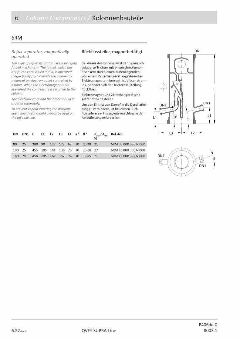
6 Column Components / Kolonnenbauteile
6.22-Rev. 0 QVF® SUPRA-LineP406de.0
8003.1
This type of re� ux separator uses a swinging funnel mechanism. The funnel, which has a so� iron core sealed into it, is operated magne� cally from outside the column by means of an electromagnet controlled by a � mer. When the electromagnet is not energised the condensate is returned to the column. The electromagnet and the � mer should be ordered separately.To prevent vapour entering the dis� llate line a liquid seal should always be used on the o� -take line.
Refux separator, magne� cally operated
Bei dieser Ausführung wird der beweglich gelagerte Trichter mit eingeschmolzenem Eisenkern durch einen außenliegenden, von einem Zeitschaltgerät angesteuerten Elektromagneten, bewegt. Ist dieser strom-los, be� ndet sich der Trichter in Stellung Rück� uss.
Elektromagnet und Zeitschaltgerät sind getrennt zu bestellen.
Um den Eintri� von Dampf in die Des� llatlei-tung zu verhindern, ist bei diesen Rück-� ußteilern ein Flüssigkeitsverschluss in der Ablau� eitung erforderlich.
Rück� ussteiler, magnetbetä� gt
6RM
DN DN1 L L1 L2 L3 L4 a ° � ° Afree / Afrei %
Ref.-No.
80 25 380 90 127 122 62 10 25-30 21 6RM 08 000 330 N 000
100 25 455 105 141 136 76 10 25-30 27 6RM 10 000 330 N 000
150 25 455 105 167 162 76 10 15-25 21 6RM 15 000 330 N 000

6 Column Components / Kolonnenbauteile
6.23-Rev. 0QVF® SUPRA-LineP406de.08003.1
6RP
This version has a swivel arm with collec� ng cup which is moved through a pneuma� c actuator. All the parts of this version in contact with the product are borosilicate glass 3.3 or PTFE.The pneuma� c actuators used are single-ac� ng, i.e. in the event of power failure a spring returns the unit into the safety posi� on total re� ux. The � mer required has to be ordered separately.To prevent vapour entering the dis� llate line, a liquid seal should always be used on the o� -take line.The product should be solid free and should not interfere with the ball-valve.
Refux separator, pneuma� cally operated
Ein Schwenkarm mit Au� angtasse wird von einem Kugelhahn mit pneuma� schem Dreh-antrieb horizontal hin- und herbewegt. Alle mediumberührten Teile dieser Ausführung sind aus Borosilicatglas 3.3 oder PTFE.
Die verwendeten pneuma� schen Drehantriebe sind einfachwirkend, d.h. bei Stromausfall bewirkt die Federkra� die Sicherheitsstellung totaler Rücklauf.
Das entsprechende Zeitschaltgerät ist ge-trennt zu bestellen.
Um den Eintri� von Dampf in die Des� llat-leitung zu verhindern, ist bei diesen Rück-� ußteilern immer ein Flüssigkeitsverschluss in der Ablau� eitung erforderlich.
Das Produkt darf keine Feststo� e enthalten und nicht die Beweglichkeit des Kugelven� les behindern.
Rück� ussteiler, pneuma� sch
DN DN1 DN2 L L1 L2 L3 L4 Afree / Afrei %
Ref.-No.
200 40 25 375 399 137 175 25 16 6RP 20 000 330 N 000
300 40 25 450 442 137 225 50 16 6RP 30 000 330 N 000
450 40 25 550 517 162 298 50 20 6RP 45 000 330 N 000

6 Column Components / Kolonnenbauteile
6.24-Rev. 0 QVF® SUPRA-LineP406de.0
8003.1
In this re� ux separator an arm is rotated by a pneuma� c actuator with magne� c clutch horizontally through an angle of 45° to each side. All the parts of this version in contact with the product are borosilicate glass 3.3 and PTFE.The pneuma� c actuators are single-ac� ng or double-ac� ng. In the event of power failure a spring returns the single-ac� ng unit to the safety posi� on total re� ux. The required � mer has to be ordered separately.To prevent vapour entering the dis� llate line, the o� -take line from these re� ux separators should be designed to form a liquid seal.
Refux separator, external, single-ac� ng
Bei diesem Rück� ussteiler wird ein Dreharm von einen pneuma� schen Antrieb mit Magnetkupplung horizontal um einen Winkel von 45° nach rechts und links gedreht.
Alle mediumberührten Teile dieser Ausführung sind aus Borosilicatglas 3.3 und PTFE.
Die verwendeten pneuma� schen Drehan-triebe sind einfach- oder doppeltwirkend. Bei Stromausfall bewirkt die Federkra� des einfachwirkenden Drehantriebs eine Rück-stellung in die Sicherheitsstellung totaler Rücklauf.
Ein Zeitschaltgerät ist getrennt zu bestellen.
Um den Eintri� von Dampf in die Des� llat-leitung zu verhindern, ist bei diesen Rück-� ussteilern durch entsprechende Rohrlei-tungsführung ein Flüssigkeitsverschluss zu gestalten.
AusführungsvariantenType of pneuma� c actuator
Rück� ussteiler, außenliegend, einfachwirkend
6RE
DN DN1 DN2 DN3 L L1 L2 L3 E E1 E2 H
40 50 25 100 140 135 110 96 260 160 170 300
Type of pneuma� c actuator /Ausführung des pneuma� schen Antriebes
Ref.-No.
Single ac� ng / einfachwirkend 6RE 04 100 333 N 000
Single ac� ng with 3/2-way solenoid valve 24VDC / einfachwirkend mit 3/2-Wege Magnetven� l 24VDC
6RE 04 200 333 N 000
Double ac� ng / doppeltwirkend 6RE 04 300 333 N 000
Double ac� ng with 5/2-way solenoid valve 24VDC / doppeltwirkend mit 5/2-Wege Magnetven� l 24VDC
6RE 04 400 333 N 000

6 Column Components / Kolonnenbauteile
6.25-Rev. 0QVF® SUPRA-LineP406de.08003.1
6CF
DN DN1 L L1 L2 Ref.-No.
150 40 155 165 110 6CF 15 004 330 N 000
200 40 175 175 125 6CF 20 004 330 N 000
300 40 200 225 125 6CF 30 004 330 N 000
450 40 275 300 150 6CF 45 004 330 N 000
600 40 325 375 175 6CF 60 004 330 N 000
Column adaptor, � at type Abschlusshaube, � ach
Column adaptor, round type Abschlusshaube, rund
DN DN1 DN2 L L1 L2 Ref.-No.
80 40 25 180 110 90 6CR 08 004 333 N 000
100 50 25 230 125 125 6CR 10 005 333 N 000
150 50 25 240 150 125 6CR 15 005 333 N 000
150 80 25 255 165 125 6CR 15 008 333 N 000
200 50 40 350 175 125 6CR 20 005 333 N 000
200 80 40 375 200 150 6CR 20 008 333 N 000
200 100 40 425 225 175 6CR 20 010 333 N 000
200 150 40 450 250 200 6CR 20 015 333 N 000
300 50 40 425 225 150 6CR 30 005 333 N 000
300 80 40 475 250 175 6CR 30 008 333 N 000
300 100 40 475 275 175 6CR 30 010 333 N 000
300 150 40 550 300 225 6CR 30 015 333 N 000
450 80 50 575 325 200 6CR 45 008 333 N 000
450 150 50 675 375 250 6CR 45 015 333 N 000
450 200 50 750 350 300 6CR 45 020 333 N 000*
600 200 100 850 425 300 6CR 60 020 333 N 000*
600 300 100 850 500 400 6CR 60 030 333 N 000*
800 300 150 1250 650 500 6CR 80 030 333 N 000*
1000 300 200 1300 750 500 6CR 11 030 333 N 000*
6CR
*Reduced pressure PS (bar g) / *Reduzierter Betriebsüberdruck PS (bar)
0,8
0,7
0,7
0,6
0,6

6 Column Components / Kolonnenbauteile
6.26-Rev. 0 QVF® SUPRA-LineP406de.0
8003.1
There are di� erent versions of columns with bubble cap plates available. The standard bubble-caps supplied have a rela� vely low pressure drop. These bubble-caps can, however, be supplied with risers. The bo� om column sec� on requires a downcomer � � ed with a dip pot to provide a liquid seal.
Bubble cap tray column
Bodenkolonnen stehen in unterschiedlichen Varianten zur Verfügung. Standardmäßig vorgesehen ist eine Glocke, die sich durch einen vergleichsweise niedrigen Druckver-lust auszeichnet. Die Glocken sind auch mit Kamin lieferbar.
Der untere Kolonnenschuss benö� gt Ablaufrohre mit Abtauchtasse (Flüssigkeits-verschluss).
Kolonne, Glockenboden
6BC
DN L H H1ca.
Number of platesBoden-zahl
Caps per plateGlockenje Boden
Downcomers per plateAblaufrohreje Boden
Ref.-No.
200 1000 200 91 5 2 1 6BC 20 ??? 330 N 000
300 1000 250 116 4 5 1 6BC 30 ??? 330 N 000
450 1500 300 141 5 13 2 6BC 45 ??? 330 N 000
600 1500 375 179 4 24 2 6BC 60 ??? 330 N 000
Technical data Technische Daten
DN Bubble cap slitGlockenschlitz HxB
Afree without riser Afrei ohne Kamin%
Afree with riser Afrei mit Kamin%
Weir height / Wehrhöhemm
200 16 x 3 6,1 4,5 30
300 16 x 3 6,8 5,0 30
450 16 x 3 7,9 5,8 30
600 16 x 3 8,3 6,1 30
With downcomer / Mit Ablaufrohr 000000
With dip pot / Mit Abtauchtasse 100100
Design key Ausführungsschlüssel

6 Column Components / Kolonnenbauteile
6.27-Rev. 0QVF® SUPRA-LineP406de.08003.1
The special feature of these components is their well de� ned internal diameter in sec� on L1.
Pipe, calibrated
Diese Bauteile zeichnen sich im Bereich L1 durch einen sehr eng tolerierten Innen-durchmesser aus.
Rohr, kalibriert
6PC
6CC
These pipes have no bu� ress ends and have a very close tolerance of the internal diameter over their whole length. They are normally used for chromatography columns and are clamped between two other components.
Diese � anschlosen und über die gesamte Länge mit einem sehr eng tolerierten Innen-durchmesser versehenen Rohre werden bevorzugt zum Bau von Chromatographie-Säulen verwendet. Ihre Befes� gung erfolgt durch Zwischenspannen.
Cylinder, calibrated Zylinder, kalibriert
DN D L L1 Ref.-No.
25 25 ± 0,1 1000 860 6PC 02 086 330 N 000
40 38 ± 0,1 1000 860 6PC 04 086 330 N 000
50 50 ± 0,2 1000 860 6PC 05 086 330 N 000
80 75 ± 0,3 1000 860 6PC 08 086 330 N 000
100 100 ± 0,4 1000 840 6PC 10 084 330 N 000
150 150 ± 0,4 1000 800 6PC 15 080 330 N 000
200 200 ± 0,5 1000 800 6PC 20 080 330 N 000
300 296 ± 0,6 1000 720 6PC 30 072 330 N 000
450 446 ± 0,7 1000 660 6PC 45 066 330 N 000
DN D L Pmax, 20°C bar g / bar
Ref.-No.
300 296 ± 0,6 1000 + 3 6CC 30 100 000 N 000
450 446 ± 0,7 1000 + 1,5 6CC 45 100 000 N 000
600 590 ± 1,5 700 + 1 6CC 60 070 000 N 000

6 Column Components / Kolonnenbauteile
6.28-Rev. 0 QVF® SUPRA-LineP406de.0
8003.1
Filter plate, glass
These porous plates are made of sintered glass powder. They have fused edges and can be clamped between standard � at-� anges. These � lter plates are available in three di� erent porosity ranges.
Die aus Glasmehl gesinterten, porösen Pla� en sind am Rand verschmolzen und eignen sich zum Einspannen in Plan� ansch-Verbindungen.
Die Filterpla� en sind in drei unterschiedlichen Porositätsbereichen lieferbar.
Filterpla� e, Glas
6FG
PorositätPorosity
DN d L Ref.-No.
50 70 20 6FG 05 ??? 000 N 000
80 100 20 6FG 08 ??? 000 N 000
100 130 20 6FG 10 ??? 000 N 000
150 185 16 6FG 15 ??? 000 N 000
200 235 19 6FG 20 ??? 000 N 000
Porosity / Porosität
Pore diamter �m / Porenweite m
Design key / Ausführungsschlüssel
0 150 - 200 000
1 90 - 150 100
2 40 - 90 200

P407e.08003.1
������������� �������
2. Pipeline Components
3. Valves and Filters
4. Vessels
5. Heat Exchangers
6. Column Components
7. STIRRERS
8. Measurement and Control
9. Couplings
10. Structures and Supports
The Component System
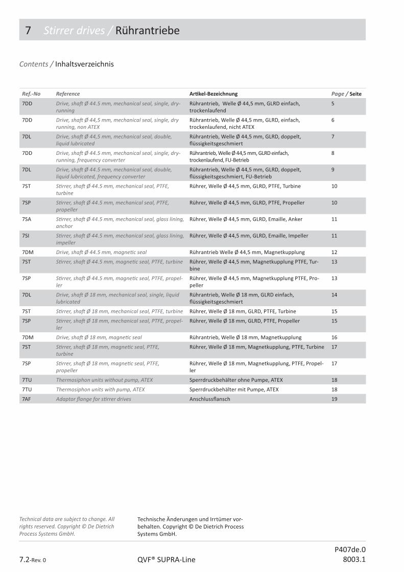
7 Stirrer drives / Rührantriebe
7.2-Rev. 0 QVF® SUPRA-LineP407de.0
8003.1
Contents / Inhaltsverzeichnis
Ref.-No Reference Ar� kel-Bezeichnung Page / Seite
7DD Drive, sha� Ø 44.5 mm, mechanical seal, single, dry-running
Rührantrieb, Welle Ø 44,5 mm, GLRD einfach, trockenlaufend
5
7DD Drive, sha� Ø 44,5 mm, mechanical seal, single, dry running, non ATEX
Rührantrieb, Welle Ø 44,5 mm, GLRD, einfach, trockenlaufend, nicht ATEX
6
7DL Drive, sha� Ø 44,5 mm, mechanical seal, double, liquid lubricated
Rührantrieb, Welle Ø 44,5 mm, GLRD, doppelt,� üssigkeitsgeschmiert
7
7DD Drive, sha� Ø 44.5 mm, mechanical seal, single, dry-running, frequency converter
Rührantrieb, Welle Ø 44,5 mm, GLRD einfach, trockenlaufend, FU-Betrieb
8
7DL Drive, sha� Ø 44.5 mm, mechanical seal, double, liquid lubricated, frequency converter
Rührantrieb, Welle Ø 44,5 mm, GLRD, doppelt, � üssigkeitsgeschmiert, FU-Betrieb
9
7ST S� rrer, sha� Ø 44.5 mm, mechanical seal, PTFE, turbine
Rührer, Welle Ø 44,5 mm, GLRD, PTFE, Turbine 10
7SP S� rrer, sha� Ø 44.5 mm, mechanical seal, PTFE, propeller
Rührer, Welle Ø 44,5 mm, GLRD, PTFE, Propeller 10
7SA S� rrer, sha� Ø 44.5 mm, mechanical seal, glass lining, anchor
Rührer, Welle Ø 44,5 mm, GLRD, Emaille, Anker 11
7SI S� rrer, sha� Ø 44.5 mm, mechanical seal, glass lining, impeller
Rührer, Welle Ø 44,5 mm, GLRD, Emaille, Impeller 11
7DM Drive, sha� Ø 44.5 mm, magne� c seal Rührantrieb Welle Ø 44,5 mm, Magnetkupplung 12
7ST S� rrer, sha� Ø 44.5 mm, magne� c seal, PTFE, turbine Rührer, Welle Ø 44,5 mm, Magnetkupplung PTFE, Tur-bine
13
7SP S� rrer, sha� Ø 44.5 mm, magne� c seal, PTFE, propel-ler
Rührer, Welle Ø 44,5 mm, Magnetkupplung PTFE, Pro-peller
13
7DL Drive, sha� Ø 18 mm, mechanical seal, single, liquid lubricated
Rührantrieb, Welle Ø 18 mm, GLRD einfach, � üssigkeitsgeschmiert
14
7ST S� rrer, sha� Ø 18 mm, mechanical seal, PTFE, turbine Rührer, Welle Ø 18 mm, GLRD, PTFE, Turbine 15
7SP S� rrer, sha� Ø 18 mm, mechanical seal, PTFE, propel-ler
Rührer, Welle Ø 18 mm, GLRD, PTFE, Propeller 15
7DM Drive, sha� Ø 18 mm, magne� c seal Rührantrieb, Welle Ø 18 mm, Magnetkupplung 16
7ST S� rrer, sha� Ø 18 mm, magne� c seal, PTFE, turbine
Rührer, Welle Ø 18 mm, Magnetkupplung, PTFE, Turbine 17
7SP S� rrer, sha� Ø 18 mm, magne� c seal, PTFE, propeller
Rührer, Welle Ø 18 mm, Magnetkupplung, PTFE, Propel-ler
17
7TU Thermosiphon units without pump, ATEX Sperrdruckbehälter ohne Pumpe, ATEX 18
7TU Thermosiphon units with pump, ATEX Sperrdruckbehälter mit Pumpe, ATEX 18
7AF Adaptor � ange for s� rrer drives Anschluss� ansch 19
Technical data are subject to change. All rights reserved. Copyright © De Dietrich Process Systems GmbH.
Technische Änderungen und Irrtümer vor-behalten. Copyright © De Dietrich Process Systems GmbH.

7 Stirrer drives / Rührantriebe
7.3-Rev. 0QVF® SUPRA-LineP407de.08003.1
E Stainless steel / Edelstahl
F Flameproof / Druckfeste Kapselung
M Magne� c drive / Magnetantrieb
N No op� on / Standard
P PTFE
X ATEX
Op� on key Sec� on 7 Variantenschlüssel Kapitel 7
Ar� cle group / Ar� kelschlüssel
Nominal diameter key / Nennweitenschlüssel
Design key 1 / Ausführungsschlüssel 1
Design key 2 / Ausführungsschlüssel 2
Op� on key / Variantenschlüssel
Sub item / Unterposi� on
7AA 00 000 000 A 000
QVF® SUPRA-Line Reference No.
Ar� cles of the QVF® SUPRA-Line component system are de� ned by a reference code of 15 characters. The code is led by the number of the catalogue sec� on and 2 le� ers linked to the English descrip� on.All other characters are used to specify the ar� cle in its group. The remaining posi� ons are � lled with “0”.In case a reference number has to be completed a “?” is shown. The right number is indicated in the op� on key table of the catalogue sec� on or the ar� cle group itself.Free space between the reference segments is not a part of the reference number it is only set to read the number easily.
QVF® SUPRA-Line Ar� kelnummern
Die Ar� kel des neuen QVF® SUPRA-Line Bauteileprogramms werden über eine 15-stellige Ar� kelnummer de� niert. Das 1.Segment - die Ar� kelgruppe - besteht aus der Kapitelzi� er und zwei Buchstaben die aus der englischen Bezeichnung des Ar� kels abgeleitet sind.
Alle weiteren Segmente dienen zur Di� eren-zierung der Ar� kel innerhalb einer Ar� kel-gruppe. Nicht benö� gte Stellen werden mit 0 aufgefüllt.
Zu ergänzende Stellen sind mit „?“ gekenn-zeichnet. Die wählbaren Bauteil-A� ribute sind ar� kelbezogen in einer Code-Tabelle aufgeführt.
Leerzeichen zwischen den einzelnen Seg-menten dienen der besseren Lesbarkeit und sind kein Bestandteil der Ar� kelnummer.

7 Stirrer drives / Rührantriebe
7.4-Rev. 0 QVF® SUPRA-LineP407de.0
8003.1
QVF® s� rrer drives are adapted for applica� ons in glass plants and are available in various designs. The maximum output torque “M” and the range of speed for the respec� ve gear/motor combina� on are speci� ed in the tables. ATEX conformity requires temperature monitoring in most cases. The measurement transducers are included in the scope of delivery. Se� ng the switch-o� /alarm at the speci� ed switch-o� temperatures must be performed at the factory.
S� rrer lengthThe proper s� rrers, whose length can be speci� ed using the “design key 2”, are herea� er assigned to the s� rrer drives. The s� rrer length determined for the vessel/cover combina� on must be extended by the value H1 of the selected s� rrer drive.Please take into account the maximum speed of the s� rrers.
Variable Speed Drive, manuallyoperatedThe speed can be changed with the drive being stopped or in opera� on. Before switching on the motor the drive should be set to its lowest speed.
Drives with reduc� on gear systems for frequency converters
These drives are equipped with a reduc� on gear system. The nominal output speed at 50 Hz is speci� ed in the tables.
Mechanical sealsVarious sliding-ring seals are used, whose permissible opera� ng temperatures must be observed regardless of the switch-o� temperatures for ATEX conformity.
Magne� c couplingsIf corrosive media are present, the stainless steel internals of the magne� c coupling must be protected with an inert gas bleed.
QVF®-Rührwerksantriebe sind auf die Anwendungen im Glasanlagenbau abge-s� mmt und in verschiedenen Ausführungen erhältlich. Das maximale Abtriebsmoment „M“ und der Drehzahlbereich für die jeweilige Getriebe/Motor-Kombina� on ist in den Tabellen angegeben.
Die ATEX-Konformität erfordert in den meisten Fällen eine Temperaturüber-wachung. Die Messwertaufnehmer sind im Lieferumfang enthalten. Die Abschaltung/Alarmierung bei den angegebenen Abschalt-temperaturen muss werksei� g erfolgen.
RührerlängenDen Rührantrieben sind nachfolgend die passenden Rührer zugeordnet, deren Länge über den „Ausführungsschlüssel 2“ angegeben werden kann. Die für die Gefäß/Hauben-Kombina� on ermi� elte Rührer-länge muss um den Wert H1 des gewählten Rührwerkes verlängert werden.
Die maximale Drehzahl der Rührer ist zu beachten.
Antriebe mit Handver-stellgetriebeDie Einstellung der Drehzahl ist im S� ll-stand und während des Betriebes möglich. Zum Einschalten ist am Getriebemotor die Drehzahl bis auf 0 zurückzunehmen.
Antriebe mit Untersetzungs-getrieb für FrequenzumrichterDiese Antriebe sind mit einem Untersetzungs-getriebe ausgesta� et. In den Tabellen ist die nominelle Abtriebsdrehzahl bei 50 Hz angegeben.
Mechanische AbdichtungenEs kommen verschiedene Gleitringdichtungen zum Einsatz, deren zulässige Betriebstem-peraturen unabhängig von den Abschalt-temperaturen der ATEX-Konformität zu beachten sind.
MagnetkupplungenDie Edelstahl-Teile der Magnetkupplung müssen bei korrosiven Medien durch eine Inertgas-Spülung geschützt werden.
Rührwerksantriebe S� rrer drives

7 Stirrer drives / Rührantriebe
7.5-Rev. 0QVF® SUPRA-LineP407de.08003.1
Rührantrieb, Welle Ø 44,5 mm, GLRD einfach, trockenlaufend
Drive,sha� Ø 44.5 mm, mechanical seal, single, dry-running,
7DD...100/200...X/F
ATEX device categoryInside vessel: 1, Outside vessel: 2Temperature switch:(TS+ in sealing plate), T4 - 100°C, T3 - 145°CMechanical seal: SiC/hard-carbon (FDA conform)TS: -20 to +150°C
ATEX-GerätekategorieIm Behälter: 1, Umgebung: 2
Abschal� emperaturen:(TS+ in der Gleitpla� e),T4 - 100°C, T3 - 145°C
Gleitringdichtung: SiC/Hartkohle (FDA konform)TS: -20 bis +150°C
Motorschutzart: erhöhte Sicherheit
Motor protec� on: increased safety
DN d1 H H1 H2 H3 PkW
Umin-1
MNm
Ref.-No.
80 2xM10 727 138 153 298 0,37 0-450 6,0 7DD 08 037 100 X 000
80 2x M10 797 138 153 298 0,55 0-450 10,2 7DD 08 055 100 X 000
80 2xM10 940 138 153 298 0,65 0-2401) 19,1 7DD 08 065 200 X 000
100 2xM10 800 138 153 298 0,65 0-450 12,8 7DD 10 065 100 X 000
100 2xM10 992 138 153 298 1,35 0-2401) 39,5 7DD 10 135 200 X 000
DN d1 H H1 H2 H3 PkW
Umin-1
MNm
Ref.-No.
80 2xM10 768 138 153 298 0,37 0-450 6,0 7DD 08 037 100 F 000
80 2xM10 839 138 153 298 0,55 0-450 10,2 7DD 08 055 100 F 000
80 2xM10 987 138 153 298 0,75 0-2401) 22 7DD 08 075 200 F 000
100 2xM10 842 138 153 298 0,75 0-450 12,8 7DD 10 075 100 F 000
100 2xM10 1006 138 153 298 1,5 0-2401) 42,5 7DD 10 150 200 F 000
Motorschutzart: druckfeste Kapselung
Motor protec� on: � ameproof enclosure
1) For anchor s� rrer mechanically reduced speed 1) Für Ankerrührer mechanisch reduzierte Ge- schwindigkeit
1) For anchor s� rrer mechanically reduced speed 1) Für Ankerrührer mechanisch reduzierte Ge- schwindigkeit

7 Stirrer drives / Rührantriebe
7.6-Rev. 0 QVF® SUPRA-LineP407de.0
8003.1
Rührantrieb, Welle Ø 44,5 mm, GLRD, einfach, trockenlaufend, nicht ATEX
Drive, sha� Ø 44,5 mm, mechanical seal, single, dry running, non ATEX
7DD...100/200 N
DN d1 H H1 H2 H3 PkW
Umin-1
MNm
Ref.-No.
80 2xM10 730 140 153 298 0,37 0-450 6,0 7DD 08 037 100 N 000
80 2xM10 800 140 153 298 0,55 0-450 10,2 7DD 08 055 100 N 000
80 2xM10 922 140 153 298 0,65 0-2401) 19,1 7DD 08 065 200 N 000
100 2xM10 800 138 153 298 0,65 0-450 12,8 7DD 10 065 100 N 000
100 2xM10 978 138 153 298 1,35 0-2401) 39,5 7DD 10 135 200 N 000
ATEX device category: noneMechanical seal: PTFE/Ceramic (FDA conform)TS: -20 to +120 °C
ATEX-Gerätekategorie: keine
Gleitringdichtung: PTFE/Keramik (FDA konform)TS: -20 bis +120 °C
1) For anchor s� rrer mechanically reduced speed 1) Für Ankerrührer mechanisch reduzierte Ge- schwindigkeit

7 Stirrer drives / Rührantriebe
7.7-Rev. 0QVF® SUPRA-LineP407de.08003.1
Rührantrieb, Welle Ø 44,5 mm, GLRD, doppelt, � üssigkeitsgeschmiert
Drive, sha� Ø 44,5 mm, mechanical seal, double, liquid lubricated
7DL 08/10...100/200 X/F
Motorschutzart: erhöhte Sicherheit
Motor protec� on: increased safety
DN d1 H H1 H2 H3 PkW
Umin-1
MNm
Ref.-No.
80 2xM10 820 230 153 388 0,37 0-450 6,0 7DL 08 037 100 X 000
80 2xM10 890 230 153 388 0,55 0-450 10,2 7DL 08 055 100 X 000
80 2xM10 1035 230 153 388 0,65 0-2401) 19,1 7DL 08 065 200 X 000
100 2xM10 890 230 153 388 0,65 0-450 12,8 7DL 10 065 100 X 000
100 2xM10 1080 230 153 388 1,35 0-2401) 39,5 7DL 10 135 200 X 000
DN d1 H H1 H2 H3 PkW
Umin-1
MNm
Ref.-No.
80 2xM10 860 230 153 388 0,37 0-450 6,0 7DL 08 037 100 F 000
80 2xM10 930 230 153 388 0,55 0-450 10,2 7DL 08 055 100 F 000
80 2xM10 1080 230 153 388 0,75 0-2401) 22,0 7DL 08 075 200 F 000
100 2xM10 930 230 153 388 0,75 0-450 12,8 7DL 10 075 100 F 000
100 2xM10 1115 230 153 388 1,50 0-2401) 39,5 7DL 10 150 200 F 000
Motorschutzart: druckfeste Kapselung
Motor protec� on: � ameproof enclosure.
ATEX device category:Inside vessel: 1, Outside vessel: 1(2)Temperature switch:(TS+ and level switch in the thermosiphon unit), TS+=50 °CMechanical seal: PTFE/Ceramic (FDA conform)TS: -20 to +150 °C
ATEX-Gerätekategorie:Im Behälter: 1, Umgebung: 1 (2)
Abschal� emperaturen:(TS+ und Niveauschalter im Sperrdruckbe-hälter), TS+=50 °C
Gleitringdichtung: PTFE/Keramik (FDA konform) TS: -20 bis +150 °C
1) For anchor s� rrer mechanically reduced speed 1) Für Ankerrührer mechanisch reduzierte Ge- schwindigkeit
1) For anchor s� rrer mechanically reduced speed 1) Für Ankerrührer mechanisch reduzierte Ge- schwindigkeit

7 Stirrer drives / Rührantriebe
7.8-Rev. 0 QVF® SUPRA-LineP407de.0
8003.1
Rührantrieb, Welle Ø 44,5 mm, GLRD einfach, trockenlaufend, FU-Betrieb
Drive, sha� Ø 44.5 mm, mechanical seal, single, dry-running, frequency converter
7DD 08/10...110/210 F
DN d1 H H1 H2 H3 PkW
Umin-1
MNm
Ref.-No.
80 2xM10 705 138 153 298 0,37 560/50Hz 6,1 7DD 08 037 110 F 000
80 2xM10 785 138 153 298 0,75 200/50Hz1) 35,8 7DD 08 075 210 F 000
100 2xM10 765 138 153 298 1,1 560/50Hz 18,8 7DD 10 110 110 F 000
100 2xM10 850 138 153 298 1,1 200/50Hz1) 50,4 7DD 10 110 210 F 000
ATEX device categoryInside vessel: 1, Outside vessel: 2Temperature switch:(TS+ in sealing plate), T4 - 100 °C, T3 - 150 °CMechanical seal: SiC/hard-carbon (FDA conform)TS: -20 to +150 °C
ATEX-GerätekategorieIm Behälter: 1, Umgebung: 2
Abschal� emperaturen:(TS+ in der Gleitpla� e), T4 - 100 °C, T3 - 145 °C
Gleitringdichtung: SiC/Hartkohle (FDA konform) TS: -20 bis +150 °C
1) For anchor s� rrer mechanically reduced speed 1) Für Ankerrührer mechanisch reduzierte Ge- schwindigkeit
Motorschutzart:druckfeste Kapselung
Motor protec� on:� ameproof enclosure

7 Stirrer drives / Rührantriebe
7.9-Rev. 0QVF® SUPRA-LineP407de.08003.1
Drive, sha� Ø 44.5 mm, mechanical seal, double, liquid lubricated, frequency converter
Rührantrieb, Welle Ø 44,5 mm, GLRD, doppelt, � üssigkeitsgeschmiert, FU-Betrieb
7DL 08/10...110/210 F
DN d1 H H1 H2 H3 Pkw
Umin-1
MNm
Ref.-No.
80 2xM10 800 230 153 388 0,37 560/50Hz 6,1 7DL 08 037 110 F 000
80 2xM10 880 230 153 388 0,75 200/50Hz1) 35,8 7DL 08 075 210 F 000
100 2xM10 855 230 153 388 1,10 560/50Hz 18,8 7DL 10 110 110 F 000
100 2xM10 940 230 153 388 1,10 200/50Hz1) 50,4 7DL 10 110 210 F 000
H2 d1
H
H3
H1
DN
Ø44,5
ATEX device category:Inside vessel: 1, Outside vessel: 1(2)Temperature switch:(TS+ and level measured in the thermosiphon unit), TS+=50 °CMechanical seal: PTFE/Ceramic (FDA conform)TS: -20 to +150 °C
ATEX-Gerätekategorie:Im Behälter: 1, Umgebung: 1 (2)
Abschal� emperaturen:(TS+ und Niveauschalter im Sperrdruckbe-hälter), TS+=50 °C
Gleitringdichtung: PTFE/Keramik (FDA konform)TS: -20 bis +150 °C
1) For anchor s� rrer mechanically reduced speed 1) Für Ankerrührer mechanisch reduzierte Ge- schwindigkeit
Motorschutzart:druckfeste Kapselung
Motor protec� on:� ameproof enclosure

7 Stirrer drives / Rührantriebe
7.10-Rev. 0 QVF® SUPRA-LineP407de.0
8003.1
7ST/SP 44...N
These s� rrers consist of a PTFE-sheathed sha� and a PTFE s� rrer element with steel core that is a� ached to the sha� to prevent twis� ng.TS: -20 to +150 °CThe PTFE of these s� rrers is dissipa� ve. The maximum length is limited to 1700 mm.
S� rrer,sha� Ø 44.5 mm, mechanical seal, PTFE
Rührer Welle Ø 44,5 mm, GLRD, PTFE
Die Rührer bestehen aus der PTFE-umman-telten Welle und dem PTFE-Rührorgan mit Stahlkern, das verdrehsicher mit der Welle verbunden wird.
TS: -20 bis +150 °C
Rührerwelle und Rührorgan werden aus ab-lei# ähigem PTFE hergestellt. Die maximale Rührerlänge beträgt 1700 mm.
Turbine Turbine
Propeller Propeller
D Ref.-No.
140 7ST 44 140 ??? P 000
D Ref.-No.
145 7SP 44 145 ??? P 000
190 7SP 44 190 ??? P 000
Design key 1: S� rrer length Example:
Ausführungsschlüssel 1: Rührerlänge Beispiel:
Length L / Länge L: 670 mm 067
Length L / Länge L: 1150 mm 115
Maximum length / maximale Länge 1700 mm 170
L mm
Umin-1
" 1200 450
" 1400 300
" 1700 250
Maximum speed 7ST/SP 44...N Maximale Drehzahl 7ST/SP 44...N

7 Stirrer drives / Rührantriebe
7.11-Rev. 0QVF® SUPRA-LineP407de.08003.1
7SA/SI 44...N
We supply one-piece impeller and anchor type glass lined steel s� rrers for mechanical seals for the use with the glass lined steel reac� on vessels. When these s� rrers are used the required power of the drive needs to be assessed. For anchor type s� rrers use drives with reduced speed.TS: -50 to +200 °C
S� rrer,sha� Ø 44.5 mm, mechanical seal, glass lining
Rührer Welle Ø 44,5 mm, GLRD, Emaille
Passen zu den emaillierten Reak� onsbe-hältern liefern wir einteilige Impeller- und Ankerrührer aus emailliertem Stahl. Beim Einsatz dieser Rührer ist die erforderliche Antriebsleistung zu überprüfen. Für Anker-rührer bieten wir Rührwerke mit reduzierter Drehzahl.
TS: -50 bis +200 °C
Anchor Anker
Impeller Impeller
L D For reac� on vessel / für Reak� onsgefäß Ref.-No.
820 335 4VR 45 025... 7SA 44 335 082 N 000
950 335 4VR 45 040... 7SA 44 335 095 N 000
985 385 4VR 45 063... 7SA 44 385 098 N 000
1020 500 4VR 60 100... 7SA 44 500 102 N 000
L D For reac� on vessel / für Reak� onsgefäß Ref.-No.
820 230 4VR 45 025... 7SI 44 230 082 N 000
950 230 4VR 45 040... 7SI 44 230 095 N 000
985 230 4VR 45 063... 7SI 44 230 098 N 000
1020 230 4VR 60 100... 7SI 44 230 102 N 000
Maximum speed of 7SA 44...N 200 rpm Maximaldrehzahl für 7SA 44...N beträgt 200 1/min
L mm
U min-1
" 1200 450
" 1400 300
" 1700 250
Maximum speed 7SI 44...N Maximale Drehzahl 7SI 44...N

7 Stirrer drives / Rührantriebe
7.12-Rev. 0 QVF® SUPRA-LineP407de.0
8003.1
7DM 08/10...X
Drive, sha� Ø 44.5 mm, magne� c seal
Rührantrieb,Welle Ø 44,5 mm, Magnetkupplung
DN d1 H H1 H2 H3 PkW
Umin-1
MNm
Ref.-No.
80 2xM10 675 193 240 266 0,37 0 - 450 6,0 7DM 08 037 100 X 000
80 2xM10 736 193 240 266 0,55 0 - 450 10,2 7DM 08 055 100 X 000
100 2xM10 675 193 240 266 0,37 0 - 450 6,0 7DM 10 037 100 X 000
100 2xM10 736 193 240 266 0,55 0 - 450 10,2 7DM 10 055 100 X 000
ATEX device category:Inside vessel: 2, Outside vessel: 2Temperature switch:(TS+ separa� ng can)T4 - 120°C, T3 - 185°CMagne� c coupling: stainless steel, nozzle for inert rendering Sha� and drive are pre-assembled
ATEX-Gerätekategorie:Im Behälter: 2, Umgebung: 2
Abschal� emperaturen:(TS+ Spal� opf), T4 - 120 °C, T3 - 185 °C
Magnetkupplung: Edelstahl, Anschluss für Inertgasüber-schleierung
Welle und Antrieb sind vormon� ert.

7 Stirrer drives / Rührantriebe
7.13-Rev. 0QVF® SUPRA-LineP407de.08003.1
S� rrer, sha� Ø 44.5 mm, magne� c seal PTFE
Rührer, Welle Ø 44,5 mm, Magnetkupplung, PTFE
7ST/SP 44...M
Propeller Propeller
D Ref.-No.
140 7ST 44 140 ??? M 000
D Ref.-No.
145 7SP 44 145 ??? M 000
190 7SP 44 190 ??? M 000
These s� rrers consist of a PTFE-sheathed sha� and a PTFE s� rrer element with steel core that is a� ached to the sha� to prevent twis� ng.TS: -20 to +150 °CThe PTFE of these s� rrers is dissipa� ve.
S� rrer length is limited to 1700 mm.
Die Rührer bestehen aus der PTFE-umman-telten Welle und dem PTFE-Rührorgan mit Stahlkern, das verdrehsicher mit der Welle verbunden wird.
TS: -20 bis +150 °C
Rührerwelle und Rührorgan werden aus ablei# ähigem PTFE hergestellt.
Maximal mögliche Rührerlänge beträgt 1700 mm.
Turbine Turbine
Design key 1: S� rrer length Example:
Ausführungsschlüssel 1: Rührerlänge Beispiel:
Length L / Länge L: 670 mm 067
Length L / Länge L: 1150 mm 115
Maximum length / maximale Länge 1700 mm 170
L mm
U min-1
" 1200 450
" 1400 300
" 1700 250
Maximum speed 7ST/SP 44...M Maximale Drehzahl 7ST/SP 44...M
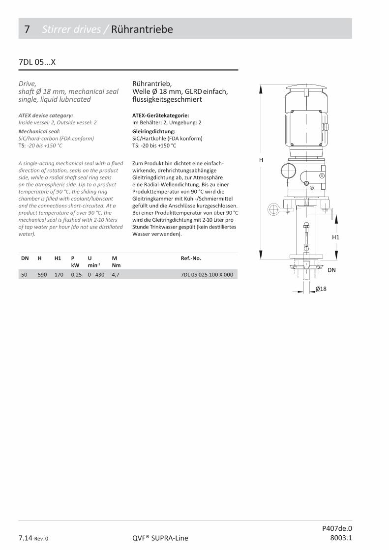
7 Stirrer drives / Rührantriebe
7.14-Rev. 0 QVF® SUPRA-LineP407de.0
8003.1
Drive, sha� Ø 18 mm, mechanical seal single, liquid lubricated
Rührantrieb,Welle Ø 18 mm, GLRD einfach, � üssigkeitsgeschmiert
7DL 05...X
DN H H1 PkW
Umin-1
MNm
Ref.-No.
50 590 170 0,25 0 - 430 4,7 7DL 05 025 100 X 000
ATEX device category:Inside vessel: 2, Outside vessel: 2Mechanical seal: SiC/hard-carbon (FDA conform)TS: -20 bis +150 °C
A single-ac� ng mechanical seal with a � xed direc� on of rota� on, seals on the product side, while a radial sha� seal ring seals on the atmospheric side. Up to a product temperature of 90 °C, the sliding ring chamber is � lled with coolant/lubricant and the connec� ons short-circuited. At a product temperature of over 90 °C, the mechanical seal is � ushed with 2-10 liters of tap water per hour (do not use dis� llated water).
ATEX-Gerätekategorie:Im Behälter: 2, Umgebung: 2
Gleiringdichtung: SiC/Hartkohle (FDA konform)TS: -20 bis +150 °C
Zum Produkt hin dichtet eine einfach-wirkende, drehrichtungsabhängige Gleitringdichtung ab, zur Atmosphäre eine Radial-Wellendichtung. Bis zu einer Produk� emperatur von 90 °C wird die Gleitringkammer mit Kühl-/Schmiermi� el gefüllt und die Anschlüsse kurzgeschlossen. Bei einer Produk� emperatur von über 90 °C wird die Gleitringdichtung mit 2-10 Liter pro Stunde Trinkwasser gespült (kein des� lliertes Wasser verwenden).

7 Stirrer drives / Rührantriebe
7.15-Rev. 0QVF® SUPRA-LineP407de.08003.1
7ST/SP 18...N
S� rrer, sha� Ø 18 mm, mechanical seal, PTFE
Rührer, Welle Ø 18 mm, GLRD, PTFE
Propeller Propeller
Turbine Turbine
Design key 1: S� rrer length Example:
Ausführungsschlüssel 1: Rührerlänge Beispiel:
Length L / Länge L: 670 mm 067
Maximum length / maximale Länge 950 mm 095
These s� rrers consist of a PTFE-sheathed sha� and a PTFE s� rrer element with steel core that is a� ached to the sha� to prevent twis� ng.TS: -20 to +150 °CThe PTFE of these s� rrers is dissipa� ve. S� rrer length is limited to 950 mm.
Die Rührer bestehen aus der PTFE-um-mantelten Welle und dem PTFE-Rührorgan mit Stahlkern, das verdrehsicher mit der Welle verbunden wird.
TS: -20 bis +150 °C
Rührerwelle und Rührorgan werden aus ablei# ähigem PTFE hergestellt.
Maximal mögliche Rührerlänge beträgt 950 mm.
D d1 Ref.-No.
90 18 7ST 18 090 ??? N 000
D d1 Ref.-No.
90 18 7SP 18 090 ??? N 000
L mm
Umin-1
" 650 450
" 850 350
" 950 300
Maximum speed 7ST/SP 18...N Maximale Drehzahl 7ST/SP 18...N

7 Stirrer drives / Rührantriebe
7.16-Rev. 0 QVF® SUPRA-LineP407de.0
8003.1
7DM 05...X
Drive, sha� Ø 18 mm, magne� c seal
Rührantrieb, Welle Ø 18 mm, Magnetkupplung
ATEX device category:Inside vessel: 2, Outside vessel: 2Temperature switch:(TS+ separa� ng can), T4 - 120 °C, T3 - 185 °CMagne� c coupling: stainless steel, connec� on for the inert gas bleed
Sha� and drive are pre-assembled
ATEX-Gerätekategorie:Im Behälter: 2, Umgebung: 2
Abschal� emperaturen:(TS+ Spal� opf), T4 - 120 °C, T3 - 185°C
Magnetkupplung: Edelstahl, Anschluss für Inertgasüber-schleierung Welle und Antrieb sind vormon� ert.
DN H H1 PkW
Umin-1
MNm
Ref.-No.
50 568 136 0,37 0-450 6,0 7DM 05 037 100 X 000

7 Stirrer drives / Rührantriebe
7.17-Rev. 0QVF® SUPRA-LineP407de.08003.1
7ST/SP 18...M
S� rrer, sha� Ø 18 mm, magne� c seal , PTFE
Rührer, Welle Ø 18 mm, Magnetkupplung, PTFE
These s� rrers consist of a PTFE-sheathed sha� and a PTFE s� rrer element with steel core that is a� ached to the sha� to prevent twis� ng.
TS: -20 to +150 °C
The PTFE of these s� rrers is dissipa� ve. For construc� on reasons the maximum possible s� rrer length is limited to 950 mm.
Die Rührer bestehen aus der PTFE-umman-telten Welle und dem PTFE-Rührorgan mit Stahlkern, das verdrehsicher mit der Welle verbunden wird.
TS: -20 bis +150 °C
Rührerwelle und Rührorgan werden aus ablei# ähigem PTFE hergestellt. Aus kon-struk� ven Gründen beträgt die maximal mögliche Rührerlänge 950 mm.
Propeller Propeller
D d1 Ref.-No.
90 18 7ST 18 090 ??? M 000
Turbine Turbine
Design key 1: S� rrer length Example:
Ausführungsschlüssel 1: Rührerlänge Beispiel:
Length L / Länge L: 670 mm 067
Maximum length / maximale Länge 950 mm 095
D d1 Ref.-No.
90 18 7SP 18 090 ??? M 000
Lmm
U min-1
" 650 450
" 850 350
" 950 300
Maximum speed 7ST/SP 18...M Maximale Drehzahl 7ST/SP 18...M
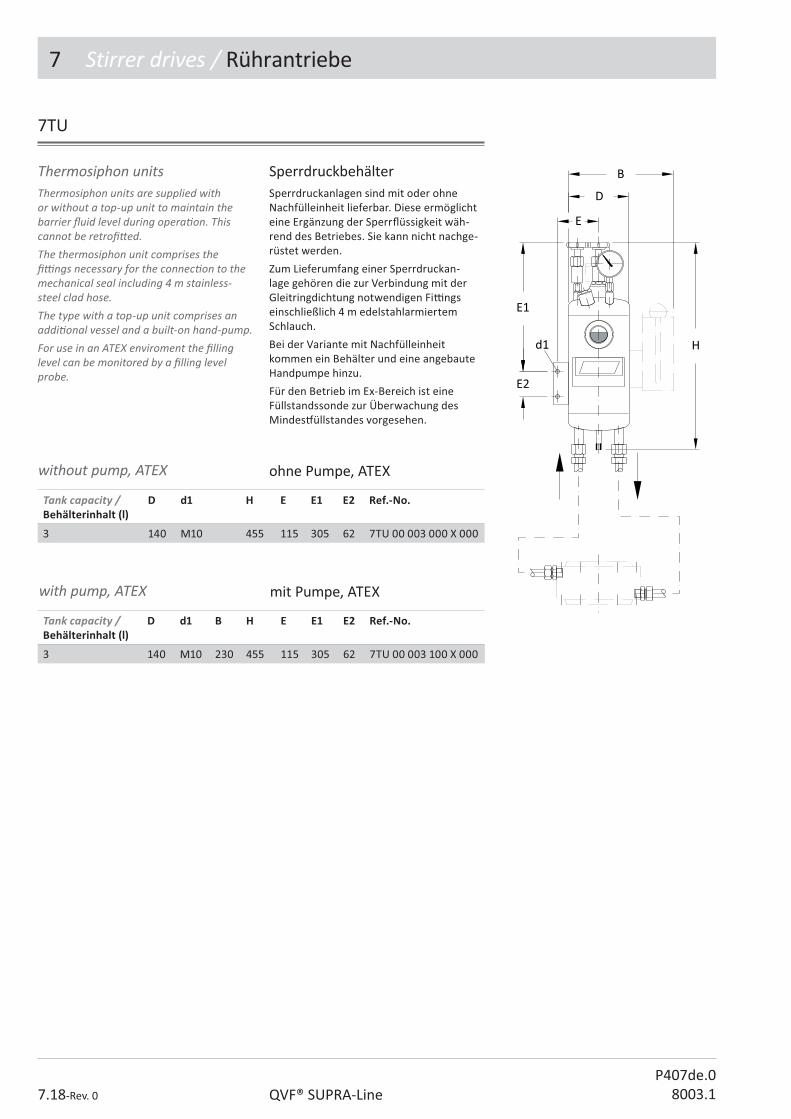
7 Stirrer drives / Rührantriebe
7.18-Rev. 0 QVF® SUPRA-LineP407de.0
8003.1
7TU
Thermosiphon units are supplied with or without a top-up unit to maintain the barrier � uid level during opera� on. This cannot be retro� � ed.The thermosiphon unit comprises the � � ngs necessary for the connec� on to the mechanical seal including 4 m stainless-steel clad hose. The type with a top-up unit comprises an addi� onal vessel and a built-on hand-pump.For use in an ATEX enviroment the � lling level can be monitored by a � lling level probe.
Thermosiphon units SperrdruckbehälterSperrdruckanlagen sind mit oder ohne Nachfülleinheit lieferbar. Diese ermöglicht eine Ergänzung der Sperr� üssigkeit wäh-rend des Betriebes. Sie kann nicht nachge-rüstet werden.
Zum Lieferumfang einer Sperrdruckan-lage gehören die zur Verbindung mit der Gleitringdichtung notwendigen Fi& ngs einschließlich 4 m edelstahlarmiertem Schlauch.
Bei der Variante mit Nachfülleinheit kommen ein Behälter und eine angebaute Handpumpe hinzu.
Für den Betrieb im Ex-Bereich ist eine Füllstandssonde zur Überwachung des Mindes# üllstandes vorgesehen.
Tank capacity / Behälterinhalt (l)
D d1 B H E E1 E2 Ref.-No.
3 140 M10 230 455 115 305 62 7TU 00 003 100 X 000
Tank capacity / Behälterinhalt (l)
D d1 H E E1 E2 Ref.-No.
3 140 M10 455 115 305 62 7TU 00 003 000 X 000
without pump, ATEX ohne Pumpe, ATEX
with pump, ATEX mit Pumpe, ATEX
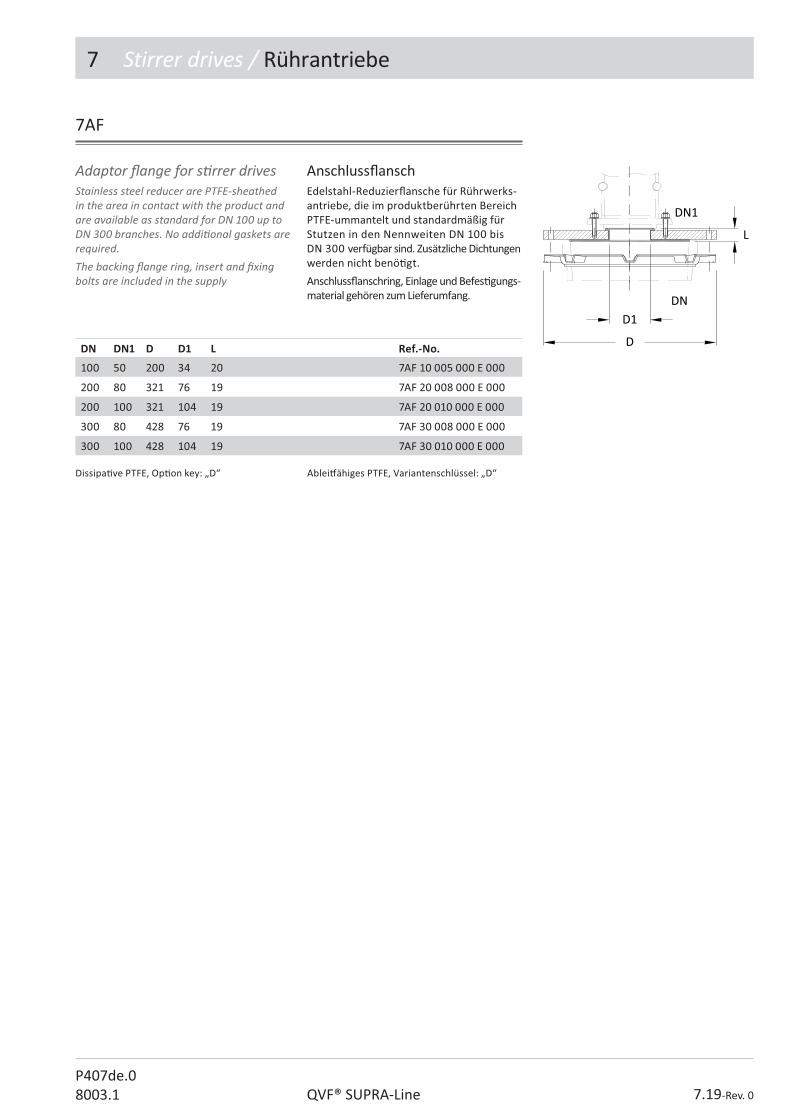
7 Stirrer drives / Rührantriebe
7.19-Rev. 0QVF® SUPRA-LineP407de.08003.1
7AF
Stainless steel reducer are PTFE-sheathed in the area in contact with the product and are available as standard for DN 100 up to DN 300 branches. No addi� onal gaskets are required.The backing � ange ring, insert and � xing bolts are included in the supply
Adaptor � ange for s� rrer drives Anschluss� anschEdelstahl-Reduzier� ansche für Rührwerks-antriebe, die im produktberührten Bereich PTFE-ummantelt und standardmäßig für Stutzen in den Nennweiten DN 100 bis DN 300 verfügbar sind. Zusätzliche Dichtungen werden nicht benö� gt.
Anschluss� anschring, Einlage und Befes� gungs-material gehören zum Lieferumfang.
DN DN1 D D1 L Ref.-No.
100 50 200 34 20 7AF 10 005 000 E 000
200 80 321 76 19 7AF 20 008 000 E 000
200 100 321 104 19 7AF 20 010 000 E 000
300 80 428 76 19 7AF 30 008 000 E 000
300 100 428 104 19 7AF 30 010 000 E 000
Dissipa� ve PTFE, Op� on key: „D“ Ablei# ähiges PTFE, Variantenschlüssel: „D“

P408e.08003.1
������������� �������
2. Pipeline Components
3. Valves and Filters
4. Vessels
5. Heat Exchangers
6. Column Components
������������
8. MEASUREMENT AND CONTROL
9. Couplings
10. Structures and Supports
The Component System

8 Measurement & Control / Mess- & Regelgeräte
8.2-Rev. 0 QVF® SUPRA-LineP408de.0
8003.1
Contents / Inhaltsverzeichnis
Ref.-No. Reference Ar� kel-Bezeichnung Page / Seite
Generell Informa� on Allgemeine Informa� onen 4-5
8RD Remote display, temperature, category 1G Fernanzeige, Temperatur-, Kategorie 1G 6
8RS Resistance thermometer, straight, category 2G Widerstandsthermometer, gerade, Kategorie 2G 8
8RA Resistance thermometer, angled 45°, category 2G Widerstandsthermometer, 45°, Kategorie 2G 8
8RX Resistance thermometer, category 1G Widerstandsthermometer, Kategorie 1G 9
8TP Thermometer pocket with screw cap Thermometerhülse mit Schraubkappe 10
8PG Pressure gauge Manometer 12
8PG Pressure gauge with contact device Manometer mit Kontakt 12
8PT Pressure transmi� er Druckmessumformer 13
8FL Flowmeter, local Durch� ussmesser, lokal 14
8FT Flowmeter with transducer Durch� ussmesser mit Messumformer 15/16
8FC Flowmeter with switch Durch� ussmesser mit Kontakteinrichtung 17/18
8LM Level measurement, electrical Niveau-Messeinrichtung, elektrisch 19
8LM Magne� c � oat, electrical level, measurement device Magnetschwimmer für Niveau-Messeinrichtung 20
8LM Float trap, electrical level, measurement device Schwimmerfänger für Niveau-Messeinrichtung 20
8MR Magnet for re� ux separator Magnet für Rück� ussteiler 21
8TE Timer, electric Zeitgeber, elektrisch 22
8TX Timer, Ex, pneuma� c Zeitgeber, Ex, pneuma� sch 23
8MC Measuring chamber, pH-electrodes Messkammer, pH-Elektroden 23
8ES Electroden holder, straight Elektrodenhalter, gerade 24
8EA Electroden holder, angled 45° Elektrodenhalter, gebogen 45° 24
8IE Interface measurement, electrical Trennschichtmessung, elektrisch 25
8IP Interface measurement, pneuma� c Trennschichtmessung, pneuma� sch 25
Technical data are subject to change. All rights reserved. Copyright © De Dietrich Process Systems GmbH.
Technische Änderungen und Irrtümer vor-behalten. Copyright © De Dietrich Process Systems GmbH.
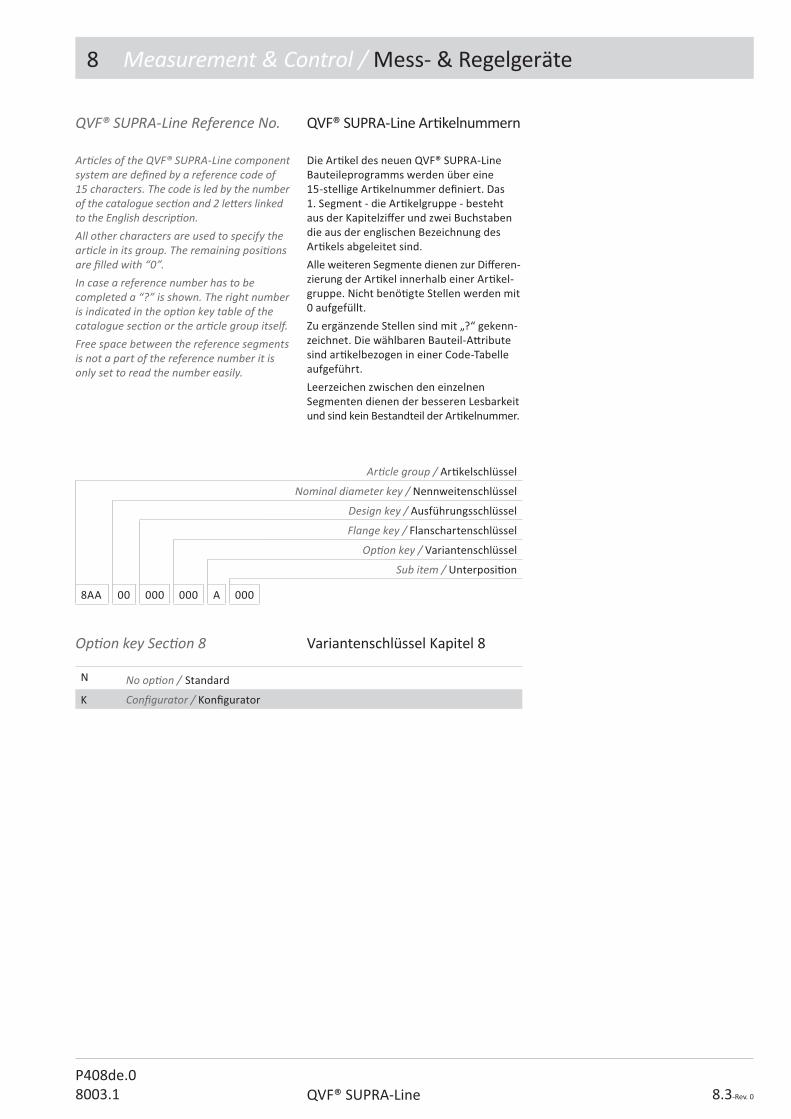
8 Measurement & Control / Mess- & Regelgeräte
8.3-Rev. 0QVF® SUPRA-LineP408de.08003.1
Op� on key Sec� on 8 Variantenschlüssel Kapitel 8
N No op� on / Standard
K Con� gurator / Kon� gurator
Ar� cle group / Ar� kelschlüssel
Nominal diameter key / Nennweitenschlüssel
Design key / Ausführungsschlüssel
Flange key / Flanschartenschlüssel
Op� on key / Variantenschlüssel
Sub item / Unterposi� on
8AA 00 000 000 A 000
QVF® SUPRA-Line Reference No.
Ar� cles of the QVF® SUPRA-Line component system are de� ned by a reference code of 15 characters. The code is led by the number of the catalogue sec� on and 2 le� ers linked to the English descrip� on.All other characters are used to specify the ar� cle in its group. The remaining posi� ons are � lled with “0”.In case a reference number has to be completed a “?” is shown. The right number is indicated in the op� on key table of the catalogue sec� on or the ar� cle group itself.Free space between the reference segments is not a part of the reference number it is only set to read the number easily.
QVF® SUPRA-Line Ar� kelnummern
Die Ar� kel des neuen QVF® SUPRA-Line Bauteileprogramms werden über eine 15-stellige Ar� kelnummer de� niert. Das 1. Segment - die Ar� kelgruppe - besteht aus der Kapitelzi� er und zwei Buchstaben die aus der englischen Bezeichnung des Ar� kels abgeleitet sind.
Alle weiteren Segmente dienen zur Di� eren-zierung der Ar� kel innerhalb einer Ar� kel-gruppe. Nicht benö� gte Stellen werden mit 0 aufgefüllt.
Zu ergänzende Stellen sind mit „?“ gekenn-zeichnet. Die wählbaren Bauteil-A� ribute sind ar� kelbezogen in einer Code-Tabelle aufgeführt.
Leerzeichen zwischen den einzelnen Segmenten dienen der besseren Lesbarkeit und sind kein Bestandteil der Ar� kelnummer.

8 Measurement & Control / Mess- & Regelgeräte
8.4-Rev. 0 QVF® SUPRA-LineP408de.0
8003.1
Generell informa� on / Allgemeine Informa� onen
QVF® measurement and control equipment complement the component range and ensures that borosilicate glass 3.3 plant and apparatus operates safely. The range of standard equipment is described on the following pages. Reference is made in the par� cular product descrip� on of special versions that can be supplied on request.In addi� on to the individual items of equipment we can also supply complete control loops, control cabinets, measurement and control systems and process control systems.
Classi� ca� on of zones Hazardous areas are classi� ed into zones based on the frequency and dura� on of the occurrence of explosive atmospheres. In Zones 0 and 1 only electrical equipment may be used for which a cer� � cate of conformity or a type examina� on cer� � cate exists; in Zone 0, however, only apparatus speci� cally cer� � ed for this purpose may be installed.
QVF®-Mess-, Steuer- und Regelgeräte ergänzen das Bauteileprogramm und gewährleisten einen sicheren Betrieb von Apparaten und Anlagen aus Borosilicatglas 3.3.
Das Programm der standardmäßig liefer-baren Geräte ist auf den folgenden Seiten beschrieben. Auf Anfrage lieferbare Sonderausführungen sind bei der jeweiligen Produktbeschreibung erwähnt.
Neben Einzelgeräten liefern wir auch komple� e Regelkreise, Schaltschränke, MSR-Anlagen und Prozessleitsysteme.
ZoneneinteilungExplosionsgefährdete Bereiche werden nach Häu� gkeit und Dauer des Au� retens von explosionsfähiger Atmosphäre in Zonen unterteilt.
In den Zonen 0 und 1 dürfen nur elektrische Betriebsmi� el verwendet werden, für die eine Konformitätsbescheinigung oder Bau-musterprü$ escheinigung vorliegt, in Zone 0 jedoch nur solche, die hierfür ausdrücklich zugelassen sind.
Gases, vapours, mistsGase, Dämpfe, Nebel
CategoryKategorie
Poten� ally explosive atmosphere presentExplosionsfähige Atmosphäre ist vorhanden
Zone 0 1 G Con� nuously or for long periods or frequently /Ständig oder langzei� g oder häu� g
Zone 1 2 G Occasionally / Gelegentlich
Zone 2 3 G Rarely or for short periods / Selten und kurzzei� g
Stäube werden in die Zonen 20, 21 und 22 einge-teilt und entsprechen der Kategorie 1D, 2D, 3D (D = Dusts = Stäube).
Dusts are classi� ed in Zones 20, 21 and 22 and correspond to Categories 1D, 2D, 3D (D = Dusts).
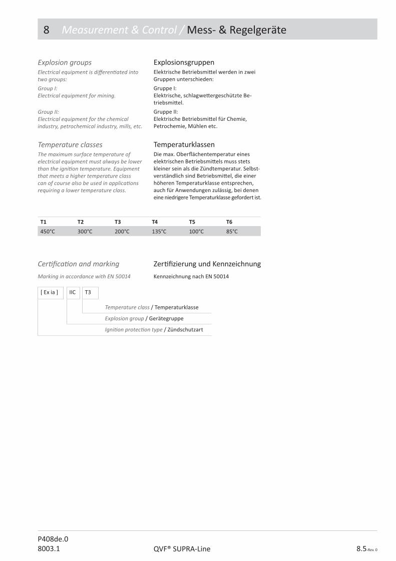
8 Measurement & Control / Mess- & Regelgeräte
8.5-Rev. 0QVF® SUPRA-LineP408de.08003.1
ExplosionsgruppenElektrische Betriebsmi� el werden in zwei Gruppen unterschieden:
Gruppe I: Elektrische, schlagwe� ergeschützte Be-triebsmi� el.
Gruppe II: Elektrische Betriebsmi� el für Chemie, Petrochemie, Mühlen etc.
TemperaturklassenDie max. Ober� ächentemperatur eines elektrischen Betriebsmi� els muss stets kleiner sein als die Zündtemperatur. Selbst-verständlich sind Betriebsmi� el, die einer höheren Temperaturklasse entsprechen, auch für Anwendungen zulässig, bei denen eine niedrigere Temperaturklasse gefordert ist.
Explosion groupsElectrical equipment is di� eren� ated into two groups:Group I: Electrical equipment for mining.
Group II: Electrical equipment for the chemical industry, petrochemical industry, mills, etc.
Temperature classesThe maximum surface temperature of electrical equipment must always be lower than the igni� on temperature. Equipment that meets a higher temperature class can of course also be used in applica� ons requiring a lower temperature class.
T1 T2 T3 T4 T5 T6
450°C 300°C 200°C 135°C 100°C 85°C
Cer� � ca� on and marking Zer� � zierung und Kennzeichnung
Marking in accordance with EN 50014 Kennzeichnung nach EN 50014
[ Ex ia ] IIC T3
Temperature class / Temperaturklasse
Explosion group / Gerätegruppe
Igni� on protec� on type / Zündschutzart

8 Measurement & Control / Mess- & Regelgeräte
8.6-Rev. 0 QVF® SUPRA-LineP408de.0
8003.1
8RD
Das ba� eriegespeiste Gerät zeigt die ge-messene Temperatur des angeschlossenen Widerstandsthermometer 8RS/8RA auf einer 4-stelligen Segmentanzeige an. Die Anzeige be� ndet sich in einem Edelstahlge-häuse der Schutzart IP65 und kann mit Hilfe der mitgelieferten Halterung in Augenhöhe am Gestell befes� gt werden.
The ba� ery supplied remote display can indicate the temperature measured by the resistance thermometer 8RS..., 8RA... on a 4 digit display. The body is made from stainless steel and meets the protec� on type IP65. It can be � xed at eye level in the structure with the included � � ng.
Remote display, temperature category 1G
Fernanzeige, TemperaturKategorie 1G
Measuring range / Messbereich -200...850 °C
Accuracy / Genauigkeit +/- 0,3 °C ± 1 Zi� er
Connec� on / Anschluss PT100, 2-wire / PT100, 2-Leiter
Power supply / Spannungsversorgung
1,5V Ba� erie Typ AA , alkaline or Lithium ba� ery, live � me about 3 years, „Lo Bat“ –display < 1,3V /1,5V Ba� erie Type AA , Alkaline oder Lithi-um Ba� erie, Lebensdauer ca. 3 Jahre, „Lo Bat“ –Anzeige < 1,3V
Ambient temperature / Umgebungstemperatur
-10…70 °C
Display / Anzeige Work face con� gura� on, 4-digits, height 11,5mm / frontsei� g kon� gurierbar, 4-stellig, Höhe 11,5mm
Explosion protec� on / Ex-Schutzart ATEX II 1G Ex ia IIC T4/T5
Protec� on type / Schutzart IP65
Technical data Technische Daten
Ref.-No.
Remote display / Fernanzeige 8RD 00 000 000 N 000
86
80
3150
LoBat
Hinweis:Der Austausch der Ba� erien muss außerhalb des Ex-Bereiches vorgenommen werden.
Remark:Replacement of the ba� ery has to be done in an ex-free area.

8 Measurement & Control / Mess- & Regelgeräte
8.7-Rev. 0QVF®SUPRA-Line3003.1
8RS/RA
They comply with the requirements applicable to Group II electrical opera� ng equipment for use in category 2G (zone 1) hazardous areas.The measuring sensor used in these resistance thermometers comprises a stainless steel tube with a Pt 100 built-in measuring element. This is � � ed in a borosilicate glass 3.3 protec� ve pocket with heat transfer paste in the � p.
Technische Daten
Technical data
Measuring probe / Messeinsatz
Resistance element / Messwiderstand Pt 100 acc. to IEC 751, Class A / Pt 100 nach IEC 751, Klasse A
Permissible product temperature / Zulässige Produk� emperatur
-50 ÷ +200 °C
Head / Anschlusskopf
Version / Ausführung BUKH shape / Form BUKH
Cable connection / Kabeleinführung Screw connec� on, blue / Verschraubung, blau
Permissible ambient temperature / Zulässige Umgebungstemperatur
-45 ÷ +85 °C
HART-Transmi� er /HART-Messumformer
Measuring range (standard) / Messbereich (Standard)
0 ÷ 200 °C
Output signal / Ausgangssignal 4 ÷ 20 mA HART Rev. 5.9, 2-wire / 2-Leiter
Type of explosion protec� on / Ex-Schutzart II 1G Ex ia IIC T6/T4
Materials / Werksto� e
Thermometer / Thermometer Stainless steel / Edelstahl
Protec� ve sheath / Schutzhülse Borosilicate glass3.3 / Borosilicatglas 3.3
Head / Anschlusskopf Polyamide, black / Polyamid, schwarz
explosion protec� on / Ex-Schutzart
Measuring probe / Messeinsatz II 2G Ex ia IIC T6
Sie erfüllen die Bes� mmungen für elektrische Betriebsmi� el der Gerätegruppe II beim Einsatz in explosionsgefährdeten Bereichen der Kategorie 2G (Zone 1).
Der für diese Widerstandsthermometer verwendete Messeinsatz besteht aus einem Edelstahlrohr mit eingebautem Messelement Pt 100. Er wird in eine Schutzhülse aus Borosilicatglas 3.3 eingesetzt, mit einer Wärmeleitpaste in der Spitze.
Resistance thermometercategory 2G
Widerstandsthermometer Kategorie 2G
Design-key resistance thermometer
Ausführungsschlüssel Widerstandsthermometer
Code
Flange key / Flanschausführung
Socket / Pfanne 2
Flat / Plan 3
Thermometer op� ons / Thermometerop� onen
1xPT100, 4-wire, without transmi� er / 1xPT100, 4-Leiter, ohne MU 5
2xPT100, 3-wire, without transmi� er / 2xPT100, 3-Leiter, ohne MU *) 6
1xPT100, 4-wire, with HART transmi� er / 1xPT100, 4-Leiter, mit MU, HART 7
2xPT100, 3-wire, with HART transmi� er / 2xPT100, 3-Leiter, mit MU, HART *) 8
without calibra� on / ohne Kalibrierung 0
with calibra� on at 0°/50°/120°C / mit 3-Punkt-Kalibrierung 0°/50°/120°C 5
Technische Daten
*) Ausführung bei Typ 3RA/RX nicht möglich*) not available for Typ 3RA/RX
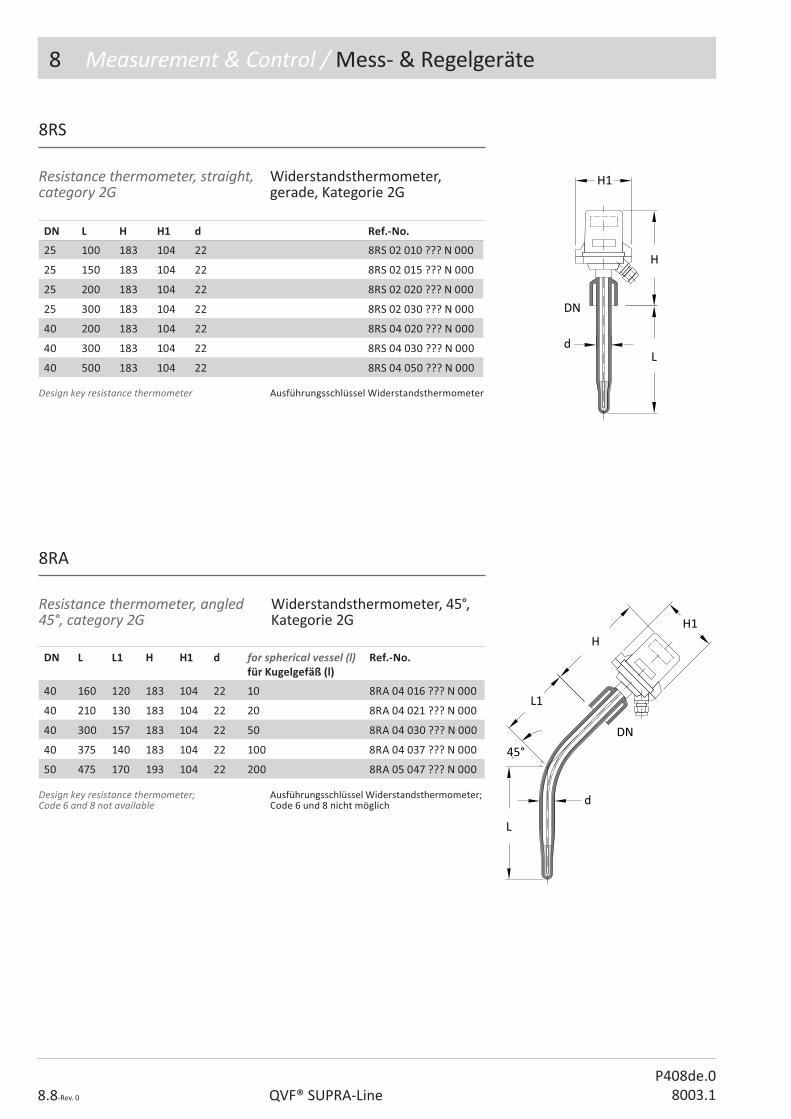
8 Measurement & Control / Mess- & Regelgeräte
8.8-Rev. 0 QVF® SUPRA-LineP408de.0
8003.1
Resistance thermometer, straight, category 2G
Widerstandsthermometer, gerade, Kategorie 2G
8RA
Resistance thermometer, angled 45°, category 2G
Widerstandsthermometer, 45°, Kategorie 2G
DN L H H1 d Ref.-No.
25 100 183 104 22 8RS 02 010 ??? N 000
25 150 183 104 22 8RS 02 015 ??? N 000
25 200 183 104 22 8RS 02 020 ??? N 000
25 300 183 104 22 8RS 02 030 ??? N 000
40 200 183 104 22 8RS 04 020 ??? N 000
40 300 183 104 22 8RS 04 030 ??? N 000
40 500 183 104 22 8RS 04 050 ??? N 000
DN L L1 H H1 d for spherical vessel (l)für Kugelgefäß (l)
Ref.-No.
40 160 120 183 104 22 10 8RA 04 016 ??? N 000
40 210 130 183 104 22 20 8RA 04 021 ??? N 000
40 300 157 183 104 22 50 8RA 04 030 ??? N 000
40 375 140 183 104 22 100 8RA 04 037 ??? N 000
50 475 170 193 104 22 200 8RA 05 047 ??? N 000
8RS
Ausführungsschlüssel WiderstandsthermometerDesign key resistance thermometer
Ausführungsschlüssel Widerstandsthermometer; Code 6 und 8 nicht möglich
Design key resistance thermometer;Code 6 and 8 not available

8 Measurement & Control / Mess- & Regelgeräte
8.9-Rev. 0QVF® SUPRA-LineP408de.08003.1
8RX
Resistance thermometer, category 1G
These thermometers complies with the requirements applicable to Group II electrical opera� ng equipment for use in category 1G (zone 0) hazardous areas.These devices consist essen� ally of a resistance thermometer with stainless steel guard tube, screw-in thread and connec� on head plus a borosilicate glass 3.3 protec� ve pocket. The two parts are joined together by means of a metal adaptor and a standard � ange coupling.
Widerstandsthermometer, Kategorie 1G
Diese Baureihe erfüllt die Bes� mmungen, die für elektrische Betriebsmi� el der Gerätegruppe II beim Einsatz in explosions-gefährdeten Bereichen der Kategorie 1G (Zone 0) Gül� gkeit haben.
Diese Geräte bestehen im Wesentlichen aus einem Widerstandsthermometer mit Edelstahlschutzrohr, Einschraubgewinde und Anschlusskopf sowie einer Schutzhülse aus Borosilicatglas 3.3.. Beide Teile werden unter Verwendung eines Metall-Adapters und einer Standard� anschverbindung mit-einander verbunden.
Technische DatenTechnical data
DN L H H1 d Ref.-No.
25 100 275 104 22 8RX 02 010 ??? N 000
25 150 275 104 22 8RX 02 015 ??? N 000
25 200 275 104 22 8RX 02 020 ??? N 000
25 300 275 104 22 8RX 02 030 ??? N 000
40 200 275 104 22 8RX 04 020 ??? N 000
40 300 275 104 22 8RX 04 030 ??? N 000
40 500 275 104 22 8RX 04 050 ??? N 000
Measuring probe / Messeinsatz
Resistance element / Messwiderstand Pt 100 acc. to IEC 751, Class A, 4 wire / Pt 100 nach IEC 751, Klasse A, 4 Leiter
Permissible product temperature / Zulässige Produk� emperatur
-50 ÷ +200 °C
Head / Anschlusskopf
Version / Ausführung BUKH shape / Form BUKH
Cable connection / Kabeleinführung Screw connec� on, blue / Verschraubung, blau
Permissible ambient temperature / Zulässige Umgebungstemperatur
-45 ÷ +85 °C
HART-transmi� er/HART-Messumformer
Measuring range (standard) / Messbereich (Standard)
0 ÷ 200 °C
Output signal / Ausgangssignal 4 ÷ 20 mA HART Rev. 5.9, 2-wire / 2-Leiter
Type of explosion protec� on / Ex-Schutzart II 1G Ex ia IIC T6/T4
Materials / Werksto� e
Thermometer / Thermometer Stainless steel / Edelstahl
Protec� ve sheath / Schutzhülse Borosilicate glass3.3 / Borosilicatglas 3.3
Head / Anschlusskopf Polyamide, black / Polyamid, schwarz
explosion protec� on / Ex-Schutzart
Measuring probe / Messeinsatz II 1G Ex ia IIC T6
Ausführungsschlüssel Widerstandsthermometer; Code 6 und 8 nicht möglich
Design key resistance thermometer;Code 6 and 8 not available

8 Measurement & Control / Mess- & Regelgeräte
8.10-Rev. 0 QVF® SUPRA-LineP408de.0
8003.1
Thermometer pocket with screw cap
Sie dienen zur Aufnahme von Stabthermo-metern oder anderen Temperaturfühlern. Eine Verbesserung des Wärmeüberganges kann durch das Einfüllen einer Kontakt-� üssigkeit oder Wärmeleitpaste in die Hülse erzielt werden.
These thermometer pockets are designed for use with stem type thermometers or other temperature probes. Improved heat transfer can be achieved by � lling the pocket with a contact � uid or heat transfer paste.
Thermometerhülse mit Schraub-kappe
8TP
DN L L1 H d d1 d2 d3 Type Ref.-No.
25 100 - 105 20 16 10 - A 8TP 02 010 ?00 N 000
25 150 - 105 20 16 10 - A 8TP 02 015 ?00 N 000
25 200 - 105 20 16 10 - A 8TP 02 020 ?00 N 000
25 300 - 105 20 16 10 - A 8TP 02 030 ?00 N 000
40 200 150 115 28 16 10 20 B 8TP 04 020 ?00 N 000
40 300 150 115 28 16 10 20 B 8TP 04 030 ?00 N 000
40 500 150 115 28 16 10 20 B 8TP 04 050 ?00 N 000
40 650 150 115 28 16 10 20 B 8TP 04 065 ?00 N 000
40 850 150 115 28 16 10 20 B 8TP 04 085 ?00 N 000
Flange key Flanschartenschlüssel
Flange / Flanschausführung Code
Plan 3
Pfanne 2
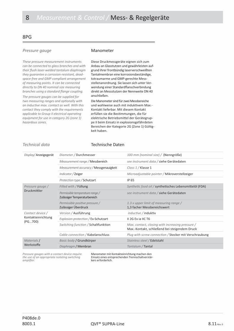
8 Measurement & Control / Mess- & Regelgeräte
8.11-Rev. 0QVF® SUPRA-LineP408de.08003.1
8PG
Diese Druckmessgeräte eignen sich zum Anbau an Glasstutzen und gewährleisten auf-grund ihrer frontbündig laserverschweißten Tantalmembran eine korrosionsbeständige, totraumarme und GMP-gerechte Mess-stellenanordnung. Sie lassen sich unter Ver-wendung einer Standard� anschverbindung direkt an Messstutzen der Nennweite DN 40 anschließen.
Die Manometer sind für zwei Messbereiche und wahlweise auch mit induk� vem Max.-Kontakt lieferbar. Mit diesem Kontakt erfüllen sie die Bes� mmungen, die für elektrische Betriebsmi� el der Gerätegrup-pe II beim Einsatz in explosionsgefährdeten Bereichen der Kategorie 2G (Zone 1) Gül� g-keit haben.
Technische DatenTechnical data
Manometer mit Kontakteinrichtung machen den Einsatz eines entsprechenden Trennschaltverstär-kers erforderlich.
These pressure measurement instruments can be connected to glass branches and with their � ush laser-welded tantalum diaphragm they guarantee a corrosion-resistant, dead-space-free and GMP compliant arrangement of measuring points. It can be connected directly to DN 40 nominal size measuring branches using a standard � ange coupling.The pressure gauges can be supplied for two measuring ranges and op� onally with an induc� ve max. contact as well. With this contact they comply with the requirements applicable to Group II electrical opera� ng equipment for use in category 2G (zone 1) hazardous zones.
Pressure gauges with a contact device require the use of an appropriate isola� ng switching ampli� er.
Pressure gauge Manometer
Display/ Anzeigegerät Diameter / Durchmesser 100 mm (nominal size) / (Nenngröße)
Measurement range / Messbereich see instrument data / siehe Gerätedaten
Measurement accuracy / Messgenauigkeit Class 1 / Klasse 1
Indicator / Zeiger Microadjustable pointer / Mikroverstellzeiger
Protec� on type / Schutzart IP 65
Pressure gauge / Druckmi� ler
Filled with / Füllung Synthe� c food oil / synthe� sches Lebensmi� elöl (FDA)
Permissible temperature range / Zulässiger Temperaturbereich
see instrument data / siehe Gerätedaten
Permissible posi� ve pressure / Zulässiger Überdruck
1.3 x upper limit of measuring range / 1,3 facher Messbereichswert
Contact device /Kontakteinrichtung(PG...700)
Version / Ausführung induc� ve / induk� v
Explosion protec� on / Ex-Schutzart II 2G Ex ia IIC T6
Switching func� on / Schal# unk� on Max. contact, closing with increasing pressure / Max.-Kontakt, schließend bei steigendem Druck
Cable connec� on / Kabelanschluss Plug with screw connec� on / Stecker mit Verschraubung
Materials / Werksto� e
Basic body / Grundkörper Stainless steel / Edelstahl
Diaphragm / Membran Tantalum / Tantal

8 Measurement & Control / Mess- & Regelgeräte
8.12-Rev. 0 QVF® SUPRA-LineP408de.0
8003.1
8PG...500
Pressure gauge Manometer
8PG...700
Pressure gauge with contact device
Manometer mit Kontakt
DN Class / Klasse 1bar g / bar
Temp.°C
H H2 H3 D Ref.-No.
40 -1 ÷ +1,5 +20 ÷ +140 150 60 15 100 8PG 04 015 500 N 000
40 0 ÷ +4,0 -10 ÷ +200 150 60 15 100 8PG 04 040 500 N 000
DN Class / Klasse 1bar g / bar
Temp.°C
H H1 H2 H3 D Ref.-No.
40 -1 ÷ +1,5 +20 ÷ +140 150 89 112 15 100 8PG 04 015 700 N 000
40 0 ÷ +4,0 -10 ÷ +200 150 89 112 15 100 8PG 04 040 700 N 000

8 Measurement & Control / Mess- & Regelgeräte
8.13-Rev. 0QVF® SUPRA-LineP408de.08003.1
8PT
Wie die Manometer gewährleisten sie aufgrund des angebauten Druckmi� lers mit seiner frontbündig laserverschweißten Tantalmembran eine produktsei� g korrosions-beständige, totraumfreie und GMP-gerechte Messstellenanordnung. Sie lassen sich unter Verwendung einer Standard� ansch-verbindung direkt an Messstutzen der Nennweite DN 40 anschließen.
Die Druckmessumformer erfüllen die Be-s� mmungen, die für elektrische Betriebs-mi� el der Gerätegruppe II beim Einsatz in explosionsgefährdeten Bereichen der Kategorie 1G (Zone 0) Gül� gkeit haben.
Technische DatenTechnical data
DN Measuring range (mbar) Messbereich (mbar abs)
H H1 H2 H3 Ref.-No.
40 0 ÷ 2000 245 63 62 119 8PT 04 200 000 N 000
The a� ached pressure gauge with its � ush laser-welded tantalum diaphragm guarantees a corrosion-resistant, dead-space-free and GMP compliant arrangement of measuring points. It can be connected direct to DN 40 nominal size measuring branches using a standard � ange coupling.These pressure transmi� ers comply with the requirements applicable to Group II electrical opera� ng equipment for use in Category 1G (zone 0) hazardous areas.
Pressure transmi� er Druckmessumformer
Pressure transmi� er / Druckmessumformer
Measurement range / Messbereich 0-4000 mbar abs pre set to 0 ÷ 2000 mbar / 0-4000 mbar absVoreinstellung auf 0 ÷ 2000 mbar
Measurement accuracy / Messgenauigkeit < ±0,2% of � nal value at 20°C / < ±0,2% vom Endwert bei 20°C
Output signal / Ausgangssignal 4 ÷ 20 mA, 2-wire, HART op� onal / 4 ÷ 20 mA, 2-Leiter, HART op� onal
Operated by / Bedienung über Graphic display / Gra� kdisplay
Protec� on type / Schutzart IP 65
Pressure gauge / Druckmi� ler
Filled with / Füllung Vacuum oil / Vakuumöl
Permissible temperature range / Zulässiger Temperaturbereich
-40 ÷ +200°C
Measurement accuracy / Messgenauigkeit 1,6 mbar/10 K
Calibra� on / Kalibrierung at 100/1000/1500 mbar / bei 100/1000/1500 mbar
Overload limit / Überlastgrenze 6/10 bar g
Materials / Werksto� e
Basic body / Grundkörper Stainless steel / Edelstahl
Diaphragm / Membran Tantalum / Tantal
explosion protec� on / Ex-Schutzart
II 1/2G Ex ia IIC T6
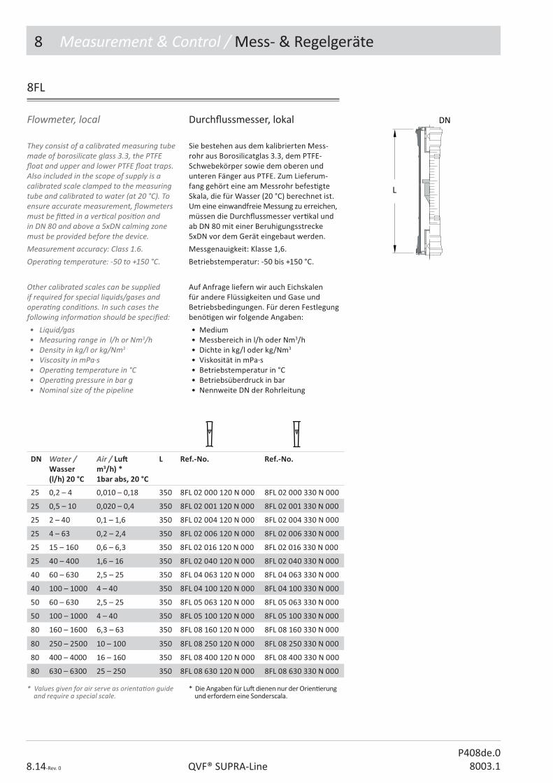
8 Measurement & Control / Mess- & Regelgeräte
8.14-Rev. 0 QVF® SUPRA-LineP408de.0
8003.1
They consist of a calibrated measuring tube made of borosilicate glass 3.3, the PTFE � oat and upper and lower PTFE � oat traps. Also included in the scope of supply is a calibrated scale clamped to the measuring tube and calibrated to water (at 20 °C). To ensure accurate measurement, � owmeters must be � � ed in a ver� cal posi� on and in DN 80 and above a 5xDN calming zone must be provided before the device. Measurement accuracy: Class 1.6.Opera� ng temperature: -50 to +150 °C.
Other calibrated scales can be supplied if required for special liquids/gases and opera� ng condi� ons. In such cases the following informa� on should be speci� ed:• Liquid/gas• Measuring range in l/h or Nm3/h• Density in kg/l or kg/Nm3
• Viscosity in mPa·s• Opera� ng temperature in °C• Opera� ng pressure in bar g• Nominal size of the pipeline
Flowmeter, local
Sie bestehen aus dem kalibrierten Mess-rohr aus Borosilicatglas 3.3, dem PTFE-Schwebekörper sowie dem oberen und unteren Fänger aus PTFE. Zum Lieferum-fang gehört eine am Messrohr befes� gte Skala, die für Wasser (20 °C) berechnet ist. Um eine einwandfreie Messung zu erreichen, müssen die Durch� ussmesser ver� kal und ab DN 80 mit einer Beruhigungsstrecke 5xDN vor dem Gerät eingebaut werden.
Messgenauigkeit: Klasse 1,6.
Betriebstemperatur: -50 bis +150 °C.
Auf Anfrage liefern wir auch Eichskalen für andere Flüssigkeiten und Gase und Betriebsbedingungen. Für deren Festlegung benö� gen wir folgende Angaben:
• Medium• Messbereich in l/h oder Nm3/h• Dichte in kg/l oder kg/Nm3
• Viskosität in mPa·s• Betriebstemperatur in °C• Betriebsüberdruck in bar• Nennweite DN der Rohrleitung
Durch� ussmesser, lokal
8FL
DN Water / Wasser(l/h) 20 °C
Air / Lu m3/h) *1bar abs, 20 °C
L Ref.-No. Ref.-No.
25 0,2 – 4 0,010 – 0,18 350 8FL 02 000 120 N 000 8FL 02 000 330 N 000
25 0,5 – 10 0,020 – 0,4 350 8FL 02 001 120 N 000 8FL 02 001 330 N 000
25 2 – 40 0,1 – 1,6 350 8FL 02 004 120 N 000 8FL 02 004 330 N 000
25 4 – 63 0,2 – 2,4 350 8FL 02 006 120 N 000 8FL 02 006 330 N 000
25 15 – 160 0,6 – 6,3 350 8FL 02 016 120 N 000 8FL 02 016 330 N 000
25 40 – 400 1,6 – 16 350 8FL 02 040 120 N 000 8FL 02 040 330 N 000
40 60 – 630 2,5 – 25 350 8FL 04 063 120 N 000 8FL 04 063 330 N 000
40 100 – 1000 4 – 40 350 8FL 04 100 120 N 000 8FL 04 100 330 N 000
50 60 – 630 2,5 – 25 350 8FL 05 063 120 N 000 8FL 05 063 330 N 000
50 100 – 1000 4 – 40 350 8FL 05 100 120 N 000 8FL 05 100 330 N 000
80 160 – 1600 6,3 – 63 350 8FL 08 160 120 N 000 8FL 08 160 330 N 000
80 250 – 2500 10 – 100 350 8FL 08 250 120 N 000 8FL 08 250 330 N 000
80 400 – 4000 16 – 160 350 8FL 08 400 120 N 000 8FL 08 400 330 N 000
80 630 – 6300 25 – 250 350 8FL 08 630 120 N 000 8FL 08 630 330 N 000
* Die Angaben für Lu� dienen nur der Orien� erung und erfordern eine Sonderscala.
* Values given for air serve as orienta� on guide and require a special scale.
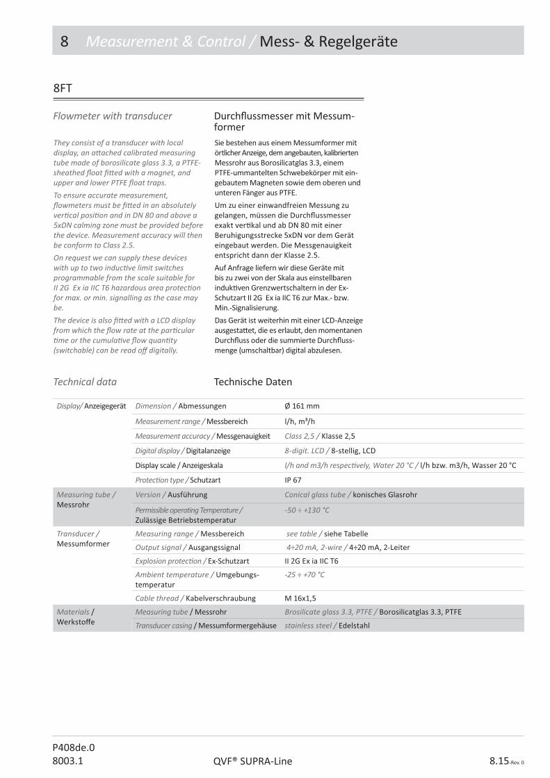
8 Measurement & Control / Mess- & Regelgeräte
8.15-Rev. 0QVF® SUPRA-LineP408de.08003.1
8FT
Sie bestehen aus einem Messumformer mit örtlicher Anzeige, dem angebauten, kalibrierten Messrohr aus Borosilicatglas 3.3, einem PTFE-ummantelten Schwebekörper mit ein-gebautem Magneten sowie dem oberen und unteren Fänger aus PTFE.
Um zu einer einwandfreien Messung zu gelangen, müssen die Durch� ussmesser exakt ver� kal und ab DN 80 mit einer Beruhigungsstrecke 5xDN vor dem Gerät eingebaut werden. Die Messgenauigkeit entspricht dann der Klasse 2.5.
Auf Anfrage liefern wir diese Geräte mit bis zu zwei von der Skala aus einstellbaren induk� ven Grenzwertschaltern in der Ex-Schutzart II 2G Ex ia IIC T6 zur Max.- bzw. Min.-Signalisierung.
Das Gerät ist weiterhin mit einer LCD-Anzeige ausgesta� et, die es erlaubt, den momentanen Durch� uss oder die summierte Durch� uss-menge (umschaltbar) digital abzulesen.
Technische DatenTechnical data
They consist of a transducer with local display, an a� ached calibrated measuring tube made of borosilicate glass 3.3, a PTFE-sheathed � oat � � ed with a magnet, and upper and lower PTFE � oat traps. To ensure accurate measurement, � owmeters must be � � ed in an absolutely ver� cal posi� on and in DN 80 and above a 5xDN calming zone must be provided before the device. Measurement accuracy will then be conform to Class 2.5.On request we can supply these devices with up to two induc� ve limit switches programmable from the scale suitable for II 2G Ex ia IIC T6 hazardous area protec� on for max. or min. signalling as the case may be. The device is also � � ed with a LCD display from which the � ow rate at the par� cular � me or the cumula� ve � ow quan� ty (switchable) can be read o� digitally.
Flowmeter with transducer Durch� ussmesser mit Messum-former
Display/ Anzeigegerät Dimension / Abmessungen Ø 161 mm
Measurement range / Messbereich l/h, m³/h
Measurement accuracy / Messgenauigkeit Class 2,5 / Klasse 2,5
Digital display / Digitalanzeige 8-digit. LCD / 8-stellig, LCD
Display scale / Anzeigeskala l/h and m3/h respec� vely, Water 20 °C / l/h bzw. m3/h, Wasser 20 °C
Protec� on type / Schutzart IP 67
Measuring tube / Messrohr
Version / Ausführung Conical glass tube / konisches Glasrohr
Permissible operating Temperature / Zulässige Betriebstemperatur
-50 ÷ +130 °C
Transducer /Messumformer
Measuring range / Messbereich see table / siehe Tabelle
Output signal / Ausgangssignal 4÷20 mA, 2-wire / 4÷20 mA, 2-Leiter
Explosion protec� on / Ex-Schutzart II 2G Ex ia IIC T6
Ambient temperature / Umgebungs-temperatur
-25 ÷ +70 °C
Cable thread / Kabelverschraubung M 16x1,5
Materials / Werksto� e
Measuring tube / Messrohr Brosilicate glass 3.3, PTFE / Borosilicatglas 3.3, PTFE
Transducer casing / Messumformergehäuse stainless steel / Edelstahl

8 Measurement & Control / Mess- & Regelgeräte
8.16-Rev. 0 QVF® SUPRA-LineP408de.0
8003.1
8FT (Con� nua� on / Fortsetzung )
If to be designed for liquids or gases other than water or air the following informa� on should be speci� ed:
• Liquid/gas• Measuring range in l/h or m³/h• Density in kg/l or kg/m³• Viscosity in mPa·s• Opera� ng temperature in °C• Opera� ng pressure in bars• Nominal size of the pipeline
Für die Auslegung auf andere Medien wie Lu� bzw. Wasser benö� gen wir folgende Angaben:
• Medium• Messbereich in l/h oder m³/h• Dichte in kg/l oder kg/m³• Viskosität in mPa·s• Betriebstemperatur in °C• Betriebsüberdruck in bar• Nennweite DN der Rohrleitung
DN Water / Wasser (l/h) 20 °C
Air / Lu (m3/h)* 1 bar abs, 20 °C
L D H H1 Ref.-No. Ref.-No.
25 16 – 160 0,5 – 5 350 161 129 11 8FT 02 001 120 N 000 8FT 02 001 330 N 000
25 25 – 250 0,85 – 8,5 350 161 129 11 8FT 02 002 120 N 000 8FT 02 002 330 N 000
25 40 – 400 1,3 – 13 350 161 129 11 8FT 02 004 120 N 000 8FT 02 004 330 N 000
25 63 – 630 2 – 20 350 161 129 11 8FT 02 006 120 N 000 8FT 02 006 330 N 000
25 100 – 1000 3,4 – 34 350 161 129 11 8FT 02 010 120 N 000 8FT 02 010 330 N 000
40 160 – 1600 5 – 50 350 161 136 11 8FT 04 016 120 N 000 8FT 04 016 330 N 000
40 250 – 2500 8,5 – 85 350 161 136 11 8FT 04 025 120 N 000 8FT 04 025 330 N 000
50 160 – 1600 5 – 50 350 161 136 11 8FT 05 016 120 N 000 8FT 05 016 330 N 000
50 250 – 2500 8,5 – 85 350 161 136 11 8FT 05 025 120 N 000 8FT 05 025 330 N 000
80 400 – 4000 13 – 130 350 161 151 11 8FT 08 040 120 N 000 8FT 08 040 330 N 000
80 630 – 6300 20 – 200 350 161 151 11 8FT 08 063 120 N 000 8FT 08 063 330 N 000
80 1000 – 10000 35 – 350 350 161 151 11 8FT 08 100 120 N 000 8FT 08 100 330 N 000
80 1600 – 16000 – 350 161 151 11 8FT 08 160 120 N 000 8FT 08 160 330 N 000
* Die Angaben für Lu� dienen nur der Orien� erung und erfordern eine Sonderscala.
* Values given for air serve as orienta� on guide � gures and require a special scale.

8 Measurement & Control / Mess- & Regelgeräte
8.17-Rev. 0QVF® SUPRA-LineP408de.08003.1
8FC
Sie bestehen aus einer örtlichen Anzeige, dem angebauten, kalibrierten Messrohr aus Borosilicatglas 3.3, einem PTFE-ummantelten Schwebekörper mit eingebautem Magneten sowie dem oberen und unteren Fänger aus PTFE.
Um zu einer einwandfreien Messung zu gelangen, müssen die Durch� ussmesser exakt ver� kal und ab DN 80 mit einer Beruhigungsstrecke 5xDN vor dem Gerät eingebaut werden. Die Messgenauigkeit entspricht dann der Klasse 2.5.
Wir liefern diese Geräte mit bis zu zwei von der Skala aus einstellbaren induk� ven Grenzwertschaltern in der Ex-Schutzart II 2G Ex ia IIC T6 zur Max.- bzw. Min.-Signalisierung.
Technische DatenTechnical data
They consist of a transducer with local display, an a� ached calibrated measuring tube made of borosilicate glass 3.3, a PTFE-sheathed � oat � � ed with a magnet, and upper and lower PTFE � oat traps. To ensure accurate measurement, � owmeters must be � � ed in an absolutely ver� cal posi� on and in DN 80 and above a 5xDN calming zone must be provided before the device. Measurement accuracy will then conform to Class 2.5.On request we can supply these devices with two induc� ve limit switches programmable from the scale suitable for II 2G Ex ia IIC T6 hazardous area protec� on for max. or min. signalling as the case may be.
Flowmeter with switch Durch� ussmesser mit Kontaktein-richtung
Display/ Anzeigegerät Dimension / Abmessungen Ø 161 mm
Measurement range / Messbereich l/h, m³/h
Measurement accuracy / Messgenauigkeit Class 2,5 / Klasse 2,5
Display scale / Anzeigeskala l/h and m3/h respec� vely, Water 20 °C / l/h bzw. m3/h, Wasser 20 °C
Protec� on type / Schutzart IP 67
Measuring tube / Messrohr
Version / Ausführung Conical glass tube / konisches Glasrohr
Permissible operating Temperature / Zulässige Betriebstemperatur
-50 ÷ +130 °C
Magne� c switch /Grenzwertschalter
induc� ve / induk� v
Explosion protec� on / Ex-Schutzart II 2G Ex ia IIC T6
Cable thread / Kabelverschraubung M 16x1,5
Materials / Werksto� e
Measuring tube / Messrohr Brosilicate glass 3.3, PTFE / Borosilicatglas 3.3, PTFE
Transducer casing / Messumformergehäuse stainless steel / Edelstahl

8 Measurement & Control / Mess- & Regelgeräte
8.18-Rev. 0 QVF® SUPRA-LineP408de.0
8003.1
8FC (Con� nua� on / Fortsetzung )
If to be designed for liquids or gases other than water or air the following informa� on should be speci� ed:
• Liquid/gas• Measuring range in l/h or m³/h• Density in kg/l or kg/m³• Viscosity in mPa·s• Opera� ng temperature in °C• Opera� ng pressure in bar g• Nominal size of the pipeline
Für die Auslegung auf andere Medien wie Lu� bzw. Wasser benö� gen wir folgende Angaben:
• Medium• Messbereich in l/h oder m³/h• Dichte in kg/l oder kg/m³• Viskosität in mPa·s• Betriebstemperatur in °C• Betriebsüberdruck in bar• Nennweite DN der Rohrleitung
DN Water / Wasser (l/h) 20 °C
Air / Lu (m³/h)* 1 bar abs, 20 °C
L D H H1 Ref.-No. Ref.-No.
25 16 – 160 0,5 – 5 350 161 129 11 8FC 02 001 120 N 000 8FC 02 001 330 N 000
25 25 – 250 0,85 – 8,5 350 161 129 11 8FC 02 002 120 N 000 8FC 02 002 330 N 000
25 40 – 400 1,3 – 13 350 161 129 11 8FC 02 004 120 N 000 8FC 02 004 330 N 000
25 63 – 630 2 – 20 350 161 129 11 8FC 02 006 120 N 000 8FC 02 006 330 N 000
25 100 – 1000 3,4 – 34 350 161 129 11 8FC 02 010 120 N 000 8FC 02 010 330 N 000
40 160 – 1600 5 – 50 350 161 136 11 8FC 04 016 120 N 000 8FC 04 016 330 N 000
40 250 – 2500 8,5 – 85 350 161 136 11 8FC 04 025 120 N 000 8FC 04 025 330 N 000
50 160 – 1600 5 – 50 350 161 136 11 8FC 05 016 120 N 000 8FC 05 016 330 N 000
50 250 – 2500 8,5 – 85 350 161 136 11 8FC 05 025 120 N 000 8FC 05 025 330 N 000
80 400 – 4000 13 – 130 350 161 151 11 8FC 08 040 120 N 000 8FC 08 040 330 N 000
80 630 – 6300 20 – 200 350 161 151 11 8FC 08 063 120 N 000 8FC 08 063 330 N 000
80 1000 – 10000 35 – 350 350 161 151 11 8FC 08 100 120 N 000 8FC 08 100 330 N 000
80 1600 – 16000 – 350 161 151 11 8FC 08 160 120 N 000 8FC 08 160 330 N 000
L
D H
DN
H1
* Die Angaben für Lu� dienen nur der Orien� erung und erfordern eine Sonderscala.
* Values given for air serve as orienta� on guide and require a special scale.
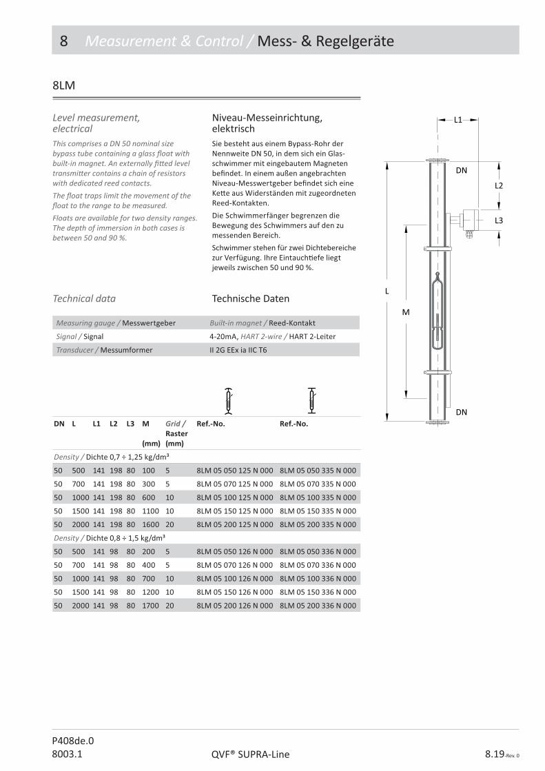
8 Measurement & Control / Mess- & Regelgeräte
8.19-Rev. 0QVF® SUPRA-LineP408de.08003.1
Level measurement, electrical
Sie besteht aus einem Bypass-Rohr der Nennweite DN 50, in dem sich ein Glas-schwimmer mit eingebautem Magneten be� ndet. In einem außen angebrachten Niveau-Messwertgeber be� ndet sich eine Ke� e aus Widerständen mit zugeordneten Reed-Kontakten.
Die Schwimmerfänger begrenzen die Bewegung des Schwimmers auf den zu messenden Bereich.
Schwimmer stehen für zwei Dichtebereiche zur Verfügung. Ihre Eintauch� efe liegt jeweils zwischen 50 und 90 %.
This comprises a DN 50 nominal size bypass tube containing a glass � oat with built-in magnet. An externally � � ed level transmi� er contains a chain of resistors with dedicated reed contacts. The � oat traps limit the movement of the � oat to the range to be measured. Floats are available for two density ranges. The depth of immersion in both cases is between 50 and 90 %.
Niveau-Messeinrichtung, elektrisch
8LM
DN L L1 L2 L3 M
(mm)
Grid /Raster(mm)
Ref.-No. Ref.-No.
Density / Dichte 0,7 ÷ 1,25 kg/dm³
50 500 141 198 80 100 5 8LM 05 050 125 N 000 8LM 05 050 335 N 000
50 700 141 198 80 300 5 8LM 05 070 125 N 000 8LM 05 070 335 N 000
50 1000 141 198 80 600 10 8LM 05 100 125 N 000 8LM 05 100 335 N 000
50 1500 141 198 80 1100 10 8LM 05 150 125 N 000 8LM 05 150 335 N 000
50 2000 141 198 80 1600 20 8LM 05 200 125 N 000 8LM 05 200 335 N 000
Density / Dichte 0,8 ÷ 1,5 kg/dm³
50 500 141 98 80 200 5 8LM 05 050 126 N 000 8LM 05 050 336 N 000
50 700 141 98 80 400 5 8LM 05 070 126 N 000 8LM 05 070 336 N 000
50 1000 141 98 80 700 10 8LM 05 100 126 N 000 8LM 05 100 336 N 000
50 1500 141 98 80 1200 10 8LM 05 150 126 N 000 8LM 05 150 336 N 000
50 2000 141 98 80 1700 20 8LM 05 200 126 N 000 8LM 05 200 336 N 000
Technical data Technische Daten
Measuring gauge / Messwertgeber Built-in magnet / Reed-Kontakt
Signal / Signal 4-20mA, HART 2-wire / HART 2-Leiter
Transducer / Messumformer II 2G EEx ia IIC T6

8 Measurement & Control / Mess- & Regelgeräte
8.20-Rev. 0 QVF® SUPRA-LineP408de.0
8003.1
Schwimmerfänger für Niveau-Messeinrichtung
Float trap, electrical level measurement device
8LM...N 00?
Magnetschwimmer für Niveau-Messeinrichtung
Magne� c � oat, electrical level measurement device
8LM...N 00?
Als Ersatzteil liefern wir Schwimmer für die Niveau-Messeinrichtung 8LM... auch für andere Dichtebereiche. Die passenden Schwimmerfänger (s. u.) sind gesondert zu bestellen.
DN Density / Dichte(kg/dm3)
L4 d Ref.-No.
50 0,7 – 1,25 400 46 8LM 05 050 335 N 001
50 0,8 – 1,50 300 46 8LM 05 050 336 N 001
Die Schwimmerfänger für die Niveau-Mes-seinrichtung Typ „8LM...“, werden ober- und unterhalb des Magnetschwimmers in die Verbindung des Messrohres eingebaut.
Aufgrund der beidsei� g angedrehten Dicht-wulst übernehmen diese Schwimmerfänger gleichzei� g die Funk� on einer Dichtung.
DN L5 n x d1 Ref.-No.
50 8 3 x 10 8LM 05 050 335 N 002
On request we can also supply � oats for type “8LM...” level measurement devices for other density ranges. Float traps (see below) should be ordered separately.
The � oat traps for the type „8LM...“ level measurement device are � � ed above and below the magne� c � oat in the measuring tube coupling. They have a built-in bead on both sides for sealing purposes and, therefore, there is no need for a separate gasket.

8 Measurement & Control / Mess- & Regelgeräte
8.21-Rev. 0QVF® SUPRA-LineP408de.08003.1
Magnet for re� ux separator
Diese U-Magnete werden zur Betä� gung von Rück� ussteilern eingesetzt. In Verbindung mit einem elektrischen Zeitgeber-Modul kann ein beweglich gelagerter Trichter mit eingeschmolzenem Eisenkern, der sich innerhalb der Kolonne be� ndet, von außen angesteuert werden.
These ‘U’ magnets are used with re� ux separators. Used in conjunc� on with an electrical � mer module a movable funnel with an iron core sealed into the glass located inside the column can be operated from outside.
Magnet für Rück� ussteiler
8MR
Technische DatenTechnical data
DN H H1 H2 H3 Ref.-No.
80 175 200 90 120 8MR 08 000 000 N 000
100 192 234 90 120 8MR 10 000 000 N 000
150 218 239 100 157 8MR 15 000 000 N 000
Supply / Versorgung DC voltage / Gleichspannung 24 VDC +/- 10%
Nominal current / Nennstrom 0,63 A
Connec� ng cable / Anschlusskabel 3xØ1,5 mm2, 1,5 m length /Länge
Digital display / Digitalanzeige 8-digit. LCD / 8-stellig, LCD
Ambient temperature / Umgebungstemperatur
-20°C ÷ +40°C
Materials / Werksto� e
Housing / Gehäuse Aluminium, varnished / Alu, lackiert
Moulding / Vergussmasse Polyurethane-based / Epoxidharz
Protec� on type / Schutzart Housing / Gehäuse IP 54
Explosion protec� on / Ex-Schutz II 2G Ex m II T4

8 Measurement & Control / Mess- & Regelgeräte
8.22-Rev. 0 QVF® SUPRA-LineP408de.0
8003.1
8TE...
Das Steuergerät ist ein elektronischer Taktgeber, der zur Steuerung des Rücklauf-verhältnisses von Rek� � ka� onskolonnen mit elektromagne� sch oder pneuma� sch betä� gten Rücklau� eilern mit Magnet-steuerven� l eingesetzt wird. Rücklauf und Ablaufzeit können am Zeitgeber von 0 Sekunden bis 100 Minuten eingestellt werden. Eine Überwachung der Siedegrenze mit einem Widerstandsthermometer (Pt 100) grei� so in die Steuerung ein, dass bei Erreichen einer eingestellten Grenztemperatur der Zeitgeber auf totalen Rücklauf oder Ablauf umschaltet und dies als Alarm-meldungen signalisiert. Nach Unterschreitung des Grenzwertes um 5K, kehrt die Steuerung wieder in den eingestellten Taktzyklus zurück. Über Tasten auf der Frontseite können alle Voreinstellungen vorgenommen werden. Es stehen außerdem 3 verschiedene Programme zur Verfügung:
Programm 0: alle Funk� onen sind wirksam
Programm 1: ohne Hupe, ohne Störmeldung
Programm 2: ohne Pt100, ohne Ausgangs- signal, ohne Störmeldung
Das oben beschriebene Steuergerät wird als Zeitgeber-Modul zum Einbau in den Schaltschrank geliefert.
Zeitgeber für Ex-Bereiche, Kategorie 2G
Für den Einsatz im Ex-Bereich wird das Zeitgeber-Modul in ein druckfestes Gehäuse mit der Schutzart II 2G Ex de (ia) IIB TGC eingebaut und kann somit als Zeitgeber für den Ex-Bereich in der Gerätegruppe II, Kategorie 2G, eingesetzt werden.
This is an electronic � mer used for controlling the re� ux ra� o in rec� � ca� on columns with electromagne� cally or pneuma� cally operated re� ux separators with magne� c control valves. The re� ux and o� take � mes can be adjusted on the � mer from 0 seconds to 100 minutes. The boiling point is monitored with a resistance thermometer (Pt 100) and this intervenes in the control so that when a preset temperature is reached the � mer switches to total re� ux or o� take and gives a warning that this has happened by sounding an alarm. A� er the temperature goes below the limit for 5K, the control returns to the preset � ming cycle. There are bu� ons on the front panel which are used to enter all the preset values. Addi� onally there are 3 di� erent programs available:
Program 0: all func� ons opera� ngProgram 1: alarm o� , fault warning o� Program 2: Pt100 o� , output signal o� , fault warning o�
The control unit described above is supplied as � mer module for rack moun� ng.Timer for hazardous areas, Category 2GFor use in hazardous areas the � mer module is built into an II 2G Ex de (ia) IIB TGC pressure resistant housing and can thus be used as a Group II, Category 2G hazardous area � mer.
Timer, electric Zeitgeber, elektrisch

8 Measurement & Control / Mess- & Regelgeräte
8.23-Rev. 0QVF® SUPRA-LineP408de.08003.1
8TX
The controller is a pneuma� c � mer used for controlling pneuma� c re� ux separators. As it operates completely pneuma� cally, it can be used without restric� on in hazardous areas. The re� ux and o� take � mes can be adjusted on the � mer from 0.3 to 10 seconds or alterna� vely from 3 to 100 seconds. There are two bu� ons which can be used, when the � mer is set to “Manual”, to switch it to total o� take or total re� ux. When set to “Automa� c” the � mer starts the preset re� ux ra� o.
Das Steuergerät ist ein pneuma� scher Taktgeber, der zur Steuerung von pneu-ma� schen Rücklau� eilern eingesetzt wird. Diese rein pneuma� sche Steuerung kann uneingeschränkt im Ex-Bereich eingesetzt werden. Rücklauf- und Ablaufzeit können am Zeitgeber von 0,3 - 10 s, alterna� v von 3 – 100 s, eingestellt werden. In der Stellung „Hand“ kann mi� els zweier Drucktasten auf totalen Ablauf oder totalen Rücklauf geschaltet werden.
8MC
Up to two commercially available electrodes with PG 13.5 thread and 120 mm long can be � � ed in the PTFE � ange. One screw thread is blanked o� as standard. The maximum opera� ng temperature is 120 °C.
Measuring chamber, pH-electrodes Messkammer, pH-Elektroden
In den PTFE-Flansch können bis zu zwei handelsübliche Elektroden mit Gewinde PG 13,5 und 120 mm Einbaulänge mon� ert werden. Ein Gewinde ist standardmäßig blindgestop� . Die max. Betriebstemperatur beträgt 120 °C.
DN DN1 DN2 L L1 H D Ref.-No. Ref.-No.
25 40 15 200 83 98 105 8MC 02 000 123 N 000 8MC 02 000 333 N 000
H
L1
L
DNDN
DN1
D
Timer, Ex, pneuma� c Zeitgeber, Ex, pneuma� sch

8 Measurement & Control / Mess- & Regelgeräte
8.24-Rev. 0 QVF® SUPRA-LineP408de.0
8003.1
The dip tubes are made of borosilicate glass 3.3 and include a PTFE assembly, in which a standard electrode with PG 13.5 thread and 120 mm length can be � � ed. The seal between glass and PTFE assembly is made of Viton.The maximum opera� ng temperature is 120 °C.
Die Eintaucharmatur aus Borosilicatglas 3.3 besitzt ein PTFE-Elektrodenhalter, in den eine handelsübliche Elektrode mit Gewinde PG 13,5 und 120 mm Einbaulänge mon� ert werden kann. Die Dichtung zwischen Glas und PTFE-Elektrodenhalter ist aus Viton gefer� gt.
Die maximale Betriebstemperatur für die Eintaucharmatur beträgt 120 °C.
8EA
Electroden holder, angled 45° Elektrodenhalter, gebogen 45°
8ES
Electroden holder, straight Elektrodenhalter, gerade
DN L H D Ref.-No.
50 500 128 37 8ES 05 050 300 N 000
50 650 128 37 8ES 05 065 300 N 000
50 850 128 37 8ES 05 085 300 N 000
DN L L1 H D Spherical vessel / Kugelgefäß
Ref.-No.
50 275 150 128 37 50 8EA 05 027 300 N 000
50 350 150 128 37 100 8EA 05 035 300 N 000
50 450 150 128 37 200 8EA 05 045 300 N 000
H
L
D
DN
H
L1
45°
DN
L
D

8 Measurement & Control / Mess- & Regelgeräte
8.25-Rev. 0QVF® SUPRA-LineP408de.08003.1
8IE
Float type measuring instruments are used for interface measurement in extrac� on columns. The � oat’s magnet system ac� vates a resistor chain in the guiding tube which corresponds to a 3-wire poten� ometer circuit. A 2-wire measurement transformer in the connec� on housing converts the resistor chain signal with a 5 mm contact grid to 4-20 mA.These � oats can only be installed from above in a branch with a minimum size of DN 80. The density of the heavy phase must be at least 0.70 kg/dm³.
Interface measurement, electrical Trennschichtmessung, elektrisch
Zur Trennschichtmessung in Extrak� ons-kolonnen werden Messwertaufnehmer eingesetzt, die nach dem Schwimmer-prinzip arbeiten. Das Magnetsystem des Schwimmers betä� gt im Gleitrohr eine Widerstandsmesske� e, die einer 3-Leiter Poten� ometerschaltung entspricht. Ein 2-Leiter Messumformer im Anschlussge-häuse wandelt das Signal der Widerstands-messke� e bei einem Kontaktraster von 5 mm in 4-20 mA.
Diese Schwimmer können nur von oben in einen Stutzen von mindestens DN 80 einge-baut werden. Die Dichte der schweren Phase muss mindestens 0,70 kg/dm³ betragen.
8IP
Float type measuring instruments are used for measuring the interface between two liquids in horizontal separators and extrac� on columns. The measurement signal is converted by means of magne� c transmission from a pneuma� c propor� onal controller into a 0.2 to 1 bar output signal. These � oats can be installed either from the side or from above in a branch with a minimum size of DN 80. The output signal at the � oat’s midpoint is 0.6 bar. The normal control range is +15mm/-15mm and this can be extended by lengthening the stem. The density of the heavy phase must be at least 0.70 kg/dm³.If the output signal is not switched directly to a pneuma� c control valve, the signal can be converted via a P/I converter (op� on) to 4-20 mA and processed in an electrical controller.
Interface measurement, pneuma� c
Trennschichtmessung, pneuma-� schZur Trennschichtmessung zwischen zwei Flüssigkeiten in liegenden Abscheidern bzw. Extrak� onskolonnen werden Mess-wertaufnehmer eingesetzt, die nach dem Schwimmerprinzip arbeiten. Das Messsignal wird mi� els magne� scher Übertragung von einem pneuma� schen Propor� onalregler in ein Ausgangssignal 0,2 bis 1 bar umgewandelt. Diese Schwimmer können sowohl seitlich als auch von oben in einen Stutzen min. DN 80 eingebaut werden. In der Mi� ellage des Schwimmers beträgt das Ausgangssignal 0,6 bar. Der normale Regelbereich beträgt +15 mm/-15 mm und kann durch Gestänge-verlängerung erweitert werden. Die Dichte der schweren Phase muss min. 0,70 kg/dm³ betragen. Wird das Ausgangssignal nicht direkt auf ein pneuma� sches Regelven� l geschaltet, kann über einen P/I-Wandler (Op� on) das Signal in 4-20 mA umgewandelt und in einer elektrischen Steuerung verar-beitet werden.
P409e.08003.1
������������� �������
2. Pipeline Components
3. Valves and Filters
4. Vessels
5. Heat Exchangers
6. Column Components
������������
8. Measurement and Control
9. COUPLINGS
10. Structures and Supports
The Component System

9 Couplings / Verbindungen
9.2-Rev. 0 QVF® SUPRA-LineP409de.0
8003.1
Contents / Inhaltsverzeichnis
Ref.-No Reference Ar� kel-Bezeichnung Page / Seite
9CL Coupling, light, complete Verbindung, leicht, komple� 6
9CH Coupling, heavy Verbindung, schwer 8
9CF Coupling, � xed point Festpunktverbindung 10
9CL Coupling, light, for spacers Verbindung, leicht, für Zwischenstück 11
9CU Coupling unit EN/ANSI Verbindungsgruppe EN/ANSI 12
9AC WPR Connec� ng coupling QVF® SUPRA-Line to WPR2002
WPR-AnschlussverbindungQVF® SUPRA-Line an WPR2002
13
9GG Gasket, glass � ange Dichtung, Glas� ansch 14
9GR Gasket, ring Dichtung, Ring 15
9GA Gasket, angular, � exible Gelenkdichtung 15
9BW Bellow glass/glass Faltenbalg Glas/Glas 17
9BW Bellow glass/EN 1092 PN10 Faltenbalg Glas/EN 1092 PN10 18
9BW Bellow glass/ANSI 150 psi Faltenbalg Glas/ANSI 150 psi 18
9BH Bellow, heavy Faltenbalg, schwer 19
9CB Coupling for bellows Verbindung, für Faltenbälge 20
9AB Adaptor plate, bellows/glass lining Anschlusspla� e, Faltenbalg/Emaile 20
9AE Adaptor plate, glass/enamel Anschlusspla� e, Glas/Emaille 21
9HP Hose, product Schlauch, Produkt 22
9HS Hose, service, glass/EN 1092 PN10 Schlauch, Service, Glas/EN 1092 PN10 23
9SC Shackl closure Bügelverschluss 23
9AS Adaptor set, for bu� er� y valves, glass/glass Anbausatz, für Klappen, Glas/Glas 24
9AS Adaptor set, for bu� er� y valves, glass/EN 1092 PN10 Anbausatz, für Klappen, Glas/EN 1092 PN10 24
Technical data are subject to change. All rights reserved. Copyright © De Dietrich Process Systems GmbH.
Technische Änderungen und Irrtümer vor-behalten. Copyright © De Dietrich Process Systems GmbH.

9 Couplings / Verbindungen
QVF® SUPRA-Line 9.3-Rev. 0
P409de.08003.1
Op� on key Sec� on 9 Variantenschlüssel Kapitel 9
N No op� on / Standard
D Dissipa� ve / ablei# ähig
E Stainless steel / Edelstahl
S steel galvanised or coated / Stahl verzinkt oder beschichtet
Nominal width key Nennweitenschlüssel
DN 15 25 40 50 80 100 150 200 300 450 600 800 1000
Code 01 02 04 05 08 10 15 20 30 45 60 80 11
Ar� cle group / Ar� kelschlüssel
Nominal diameter key / Nennweitenschlüssel
Design key / Ausführungsschlüssel
Flange key / Flanschartenschlüssel
Op� on key / Variantenschlüssel
Sub item / Unterposi� on
9AA 00 000 000 A 000
QVF® SUPRA-Line Reference No.
Ar� cles of the QVF® SUPRA-Line component system are de� ned by a reference code of 15 characters. The code is led by the number of the catalogue sec� on and 2 le� ers linked to the English descrip� on.All other characters are used to specify the ar� cle in its group. The remaining posi� ons are � lled with “0”.In case a reference number has to be completed a “?” is shown. The right number is indicated in the op� on key table of the catalogue sec� on or the ar� cle group itself.Free space between the reference segments is not a part of the reference number it is only set to read the number easily.
QVF® SUPRA-Line Ar� kelnummern
Die Ar� kel des neuen QVF® SUPRA-Line Bauteileprogramms werden über eine 15-stellige Ar� kelnummer de� niert. Das 1. Segment - die Ar� kelgruppe - besteht aus der Kapitelzi� er und zwei Buchstaben die aus der englischen Bezeichnung des Ar� kels abgeleitet sind.
Alle weiteren Segmente dienen zur Di� eren-zierung der Ar� kel innerhalb einer Ar� kel-gruppe. Nicht benö� gte Stellen werden mit 0 aufgefüllt.
Zu ergänzende Stellen sind mit „?“ gekenn-zeichnet. Die wählbaren Bauteil-A� ribute sind ar� kelbezogen in einer Code-Tabelle aufgeführt.
Leerzeichen zwischen den einzelnen Segmenten dienen der besseren Lesbarkeit und sind kein Bestandteil der Ar� kelnummer.
9 Couplings / Verbindungen
9.4-Rev. 0 QVF® SUPRA-LineP409de.0
8003.1
QVF® couplings are a strong and high duty system providing maximum reliability with the minimum of maintenance. All parts are made of cer� � ed materials according PED. By the use of deep drawn stainless steel the coupling rings up to DN 300 are light and strong.
Pipeline glass endsThe three available glass ends as ball, socket and � at have the same shoulder form. A single type of coupling is su� cient to connect ball/socket or � at/� at. Due to the material stainless steel for all parts of the connec� on can be used over the full temperature range. It complies with cGMP requirements. The glass ends and the couplings o� er compa� bility to the former WPR 2002 glass system.
SpringsA spring sets the correct pte-load over the full temperature range. Up to DN 300 the patented spring element � xes an earthing wire by turning the � ghtened clamp for 90 ° with a tool to earth the en� re equipment with one wire. The wire is � xed in a groove with a slip protec� on. From DN 450 onwards compression springs are used. The necessary bolt load for glass connec� ons is low, so the appropriate � ghtening of a coupling is set by measuring the loaded length of the spring element. Couplings in the DN 450 to DN 1000 range should be checked a� er the plant has been heated up for the � rst � me.
Introduc� on Allgemeines
QVF®-Flanschverbindungen sind kra� schlüssig und hochbelastbar und bieten bei geringstem Wartungsaufwand ein Höchstmaß an Zuverlässig-keit. Alle Bauteile bestehen aus Werksto� en, die für den Druckgerätebau zugelassen sind. Durch die Verwendung � efgezogener Edelstahl-schellenringe bis zur Nennweite DN 300 bieten sie höchste Fes� gkeit bei niedrigem Gewicht.
Flanschenden im RohrleitungsbauKugel/Pfanne- und Plan/Plan-Verbindungen besitzen einen iden� schen Block� ansch, so dass eine universelle Verbindung verwendet werden kann. Da die Universalverbindung bis zur Nennweite DN 300 komple� aus Edel-stahl besteht, kann sie über den gesamten Temperaturbereich eingesetzt werden und genügt höchsten Reinheitsanforderungen (cGMP). Die Anschlusskompa� bilität der Rohrenden und Verbindungen zum ehe-maligen WPR 2002 Glassystem ist gewähr-leistet.
FederelementeEin Federelement gewährleistet über den gesamten Temperaturbereich die notwen-dige Vorspannung für die Dichtung. Bis zur Nennweite DN 300 kommt ein zum Patent angemeldetes Federelement zum Einsatz. Dieses ermöglicht im gespannten Zustand die Anbringung eines Erdungsdrahtes, um alle Flanschringe mit einem ungeteilten Erdungsdraht an Erde anzuschließen. Dazu wird das Federelement mit einem Werk-zeug um 90 ° verdreht und spannt den Erdungsdraht sicher in einer eingeprägten Nut mit Rutschsicherung. Bei den Nenn-weiten ab DN 450 kommen Druckfedern zum Einsatz. Die erforderliche Vorspannung der Federelemente wird aufgrund der im Glasanlagenbau geringen erforderlichen Schraubenkrä� e über die gespannte Länge der Federelemente eingestellt und sollte bei den Verbindungen größer als Nennweite DN 450 nach dem Au ̀ eizen der Anlage kontrolliert werden.
9 Couplings / Verbindungen
QVF® SUPRA-Line 9.5-Rev. 0
P409de.08003.1
Gaskets Dichtungen
Glass connec� ons and connec� ons to � anges made from other materials are sealed by di� erent types of PTFE gaskets. The standard gasket up to DN 300 can be used with � at glass end and with ball/socket glass ends. With � at � anges the gasket seals at the inner circle of the sealing area and avoids any dead space. It complies with GMP requirements.
Coated glass componentsStandard couplings and inserts are used to install Sectrans coated borosilicate glass 3.3 components. The silicon shim must not be assembled with coated components.
Connec� ng to other materials
In addi� on to standard couplings for glass components, the following pages also contain solu� ons for these very di� erent applica� ons. They ensure that the normal bol� ng forces applicable to glass plant are applied to the glass without being exceeded.
Zum Abdichten von Glasverbindungen und zum Anschluss an andere Werksto� e werden PTFE-Dichtungen verschiedener Ausführungen verwendet.
Die für die Glas/Glas-Verbindung im Rohrleitungsbau bis DN 300 vorgesehene Universaldichtung kann sowohl bei Kugel/Pfanne-Verbindungen, als auch bei Plan/Plan-Verbindungen verwendet werden, wobei sie bei der Plan/Plan-Verbindung den GMP-Anforderungen entspricht und totraumarm am inneren Durchmesser abdichtet.
Glasbauteile mit BeschichtungFür die Montage von Bauteilen aus Borosili-catglas 3.3 mit Sectrans-Beschichtung sind Standard-Flanschverbindungen und -Beilagen einsetzbar. Die Silikon-Unterlage muss in diesem Falle weggelassen werden.
Verbindung mit Bauteilen aus anderen Werksto� enNeben den Standard-Flanschverbindungen für Glasbauteile sind auf den folgenden Seiten auch Lösungen für den Anschluss an andere Werksto� e gezeigt. Sie gewährleisten, dass die im Glasapparatebau üblicherweise verwendeten Schraubenkrä� e auf der Glas-seite nicht überschri� en werden.

9 Couplings / Verbindungen
9.6-Rev. 0 QVF® SUPRA-LineP409de.0
8003.1
DN D K nxd1 H L Ref.-No.Ref.-No.
DN15DN15 6666 5050 3xM63xM6 3232 3030 9CL 01 000 005 E 0009CL 01 000 005 E 000
DN25DN25 9090 7070 3xM83xM8 4545 3030 9CL 02 000 005 E 0009CL 02 000 005 E 000
DN40DN40 109109 8686 3xM83xM8 5959 3030 9CL 04 000 005 E 0009CL 04 000 005 E 000
DN50DN50 120120 9898 3xM83xM8 5959 3030 9CL 05 000 005 E 0009CL 05 000 005 E 000
DN80DN80 160160 134134 6xM86xM8 8484 3030 9CL 08 000 005 E 0009CL 08 000 005 E 000
DN100DN100 204204 178178 6xM86xM8 8080 3030 9CL 10 000 005 E 0009CL 10 000 005 E 000
DN150DN150 280280 254254 6xM86xM8 7777 3030 9CL 15 000 005 E 0009CL 15 000 005 E 000
DN200DN200 320320 295295 8xM88xM8 8080 3030 9CL 20 000 005 E 0009CL 20 000 005 E 000
DN300DN300 424424 400400 12xM812xM8 7171 3030 9CL 30 000 005 E 0009CL 30 000 005 E 000
Die Verbindung besteht aus zwei � efge-zogenen Edelstahl� anschringen, den zum Patent angemeldeten Federelementen, zwei Beilagen, zwei Silikon-Unterlagen, sowie den notwendigen Schrauben und Mu� ern. Die Nennweite DN 15 wird ohne Federelemente und Unterlage mon� ert. Die Dichtungen sind separat zu bestellen. Die Verbindungen bis zu Nennweite DN 300 werden konfek� oniert geliefert. Als Ersatz-teil können die Komponenten der Verbindung auch einzeln bestellt werden.
The complete coupling consists of two deep drawn stainless steel � anges, the spring element (applied for a patent), two inserts, two shims and the necessary bolts and nuts. Couplings DN 15 are assembled without spring element and without silicon shim. Gaskets must be ordered separately. Couplings up to DN 300 are boxed. Spare parts of the coupling can be ordered separately.
Verbindung, leicht, komple� Coupling, light, complete
9CL
Fastening torque /Anzugsmoment
L0 mm
L1 mm
DN 15DN 15 1 Nm1 Nm -- --
DN 25 - DN 40DN 25 - DN 40 -- 3030 24,524,5
Free/compresssed length spring Free/compresssed length spring elementelement
Ungespannte/gespannte Länge FederelementDie erforderliche Dichtkra� wird von den Federelementen auch beim Setzen der Dichtung aufrechterhalten. Bei Montage werden die Federn auf die angegebene gespannte Länge L1 vorgespannt.
The necessary sealing force is given by the spring elements, � ghtened during assembly to the given length L1.
9 Couplings / Verbindungen
QVF® SUPRA-Line 9.7-Rev. 0
P409de.08003.1
Die Verbindungkomponenten können mit der unten angegebenen Bestell-Referenz einzeln bestellt werden.
Flanschring, leichtMaterial: Edelstahl 1.4301
BeilageEdelstahl Spiralfeder 1.4310 mit Ein-schraubende, wird vormon� ert über das Flanschende gezogen.
Silikon UnterlageSilikon Unterlage zum Schutz des Glases gegen Kratzer. Bei beschichteten Bauteilen und DN 15 en# ällt die Unterlage.
FederelementEdelstahl 1.4310 Federelement, zum Patent angemeldet.
Das Federelement wird vorgespannt und gewährleistet über den gesamten Temperatur-bereich die notwendige Vorspannung für die Dichtung.
Bei der Nennweite DN 15 ist der Flanschring federnd ausgeführt, so dass die Federelemente en# allen.
Das Federelement ermöglicht im gespannten Zustand das Anbringen eines Erdungskabels zum Anschluss an Erde.
Schrauben & Mu� ernSchrauben und Mu� ern bestehen aus Edelstahl A2-70, gestempelt, mit Werksto� -zeugnis für den Einsatz im Druckgerätebau. Die Mu� ern sind mit einer elektrisch ablei# ähigen Gleitbeschichtung versehen. Sie werden nicht gefe� et.
Coupling parts can be ordered separately with the given order no.
Backing flange, lightBacking flange, lightMaterial: Material: stainless steel 1.4301
InsertStainless steel spring 1.4310 with screw connec� on to slip over the glass end.
Silicon shimSilicon shimSilicon shims to prevent glass surface from scratches, must not be used with coated glass parts and DN 15.
Spring elementStainless steel 1.4310 spring element, applied for a patent. The spring element has to be � ghtened to ensures the necessary sealing force over the whole temperature range. DN 15 has to be assembled without spring elements as the coupling-ring itself is elas� c.Without loosening the coupling the spring element allows to connect the coupling rings to earth.
Bolts & nutsBolts & nutsNuts and bolts are made from stainless steel and stamped for the use in pressure equipment. The nuts are coated against seizing and should not be lubricated with grease.
Ersatzteile, Verbindung leichtErsatzteile, Verbindung leichtSpare parts coupling, lightSpare parts coupling, light
Spare parts / Ersatzteile Ref.-No.
Backing � ange, light / Flanschring, leicht 9CL ?? 000 000 E 001
Insert /Insert / Beilage 9CL ?? 000 000 E 002
Silicon shim / Silikon Unterlage 9CL ?? 000 000 E 003
Spring element / Federelement 9CL 02 000 000 E 004

9 Couplings / Verbindungen
9.8-Rev. 0 QVF® SUPRA-LineP409de.0
8003.1
9CH
Coupling rings from DN 450 to DN 1000 are made from steel or cast iron and with a bonded insert. Nuts and bolts and compression springs are part of scope of supply. Spare parts of the coupling can be ordered separately.
Coupling, heavy Verbindung, schwer
Flanschringe ab der Nennweite DN 450 werden aus Gusseisen bzw. Stahl gefer� gt und sind mit einer eingeklebten Einlage versehen. Zum Lieferumfang gehören die notwendigen Schrauben und Druckfedern. Die Komponenten der Verbindung können auch einzeln bestellt werden.
DN D K nxd1 H H1 Type Ref.-No.
450450 615615 585585 16xM1216xM12 146146 AA 9CH 45 000 000 S 0009CH 45 000 000 S 000
600600 755755 710710 20xM1220xM12 173173 AA 9CH 60 000 000 S 0009CH 60 000 000 S 000
800800 996996 950950 24xM1224xM12 121121 253253 BB 9CH 80 000 000 S 0009CH 80 000 000 S 000
10001000 11701170 11201120 28xM1228xM12 123123 255255 BB 9CH 11 000 000 S 0009CH 11 000 000 S 000
Die Flanschverbindungen DN 450 und DN 600 sind auch mit gedrehten Edelstahlringen aus 1.4301 lieferbar. Variantenschlüssel: „E“
The coupling DN 450 and DN 600 can be supplied with coupling rings made from 1.4301 stainless steel. Op� on key: „E“.
d L0 (mm) L1(mm)
DN 450 - DN 1000DN 450 - DN 1000 1313 3939 3131
Free/compresssed length com-Free/compresssed length com-pression springpression spring
Ungespannte/gespannte Länge DruckfederDie erforderliche Dichtkra� wird von den Druckfedern auch beim Setzen der Dichtung aufrechterhalten. Bei Montage werden die Federn auf die angegebene gespannte Länge vorgespannt.
The necessary sealing force is provided by the compression springs � ghtened during assembly to the given length.

9 Couplings / Verbindungen
QVF® SUPRA-Line 9.9-Rev. 0
P409de.08003.1
Flanschringe, DN 450, DN 600 Epoxidharz lackiertes Gusseisen, mit ein-geklebter Einlage aus Kautschuk/Glasfaser. Die Schellenringhäl� en sind als Paar ge-kennzeichnet und dürfen nicht vertauscht werden.
Flanschring, DN 800, DN 1000 Epoxidharz lackierte Stahlringe, mit einge-klebter Einlage aus Kautschuk/Glasfaser. Die Schellenringhäl� en sind als Paar ge-kennzeichnet und dürfen nicht vertauscht werden.
DruckfedernZur Gewährleistung einer bleibenden Vor-spannung werden die Druckfedern aus dem Werksto� 1.4310 von der ungespannten Länge L0 auf die vorgespannte Länge L1 an-gezogen. Es ist erforderlich, die Federlänge nach dem ersten Au ̀ eizen der Anlage zu überprüfen.
Schrauben & Mu� ernSchrauben und Mu� ern aus A2-70, gestempelt, mit Werksto� zeugnis für den Einsatz im Druckgerätebau. Die Mu� ern sind mit einer ablei# ähigen Gleitbeschichtung versehen. Sie werden nicht gefe� et.
Backing � anges, DN 450, DN 600 Cast iron, epoxy resin coated, with bonded rubber/glass � bre inserts. The coupling ring -halfs come as marked pairs and should not be mixed up.
Backing � ange, DN 800, DN 1000 Steel, epoxy resin coated, with bonded rubber/glass � bre inserts. Each coupling ring half comes as a marked pair and should not be mixed up.
Compression springTo assure a correct bolt load the compression springs made from 1.4310 are compressed from the unloaded length of 39 mm to the compressed length of 31 mm. The compressed length has to be checked a� er the plant has been heated up for the � rst � me.
Nuts & boltsNuts & boltsNuts and bolts are made from stainless Nuts and bolts are made from stainless steel and stamped for the use in pressure steel and stamped for the use in pressure equipment. The nuts are coated against equipment. The nuts are coated against seizing and should not be lubricated with seizing and should not be lubricated with grease when tightened the first time.grease when tightened the first time.
Ersatzteile Verbindung, schwerErsatzteile Verbindung, schwerSpare parts coupling, heavySpare parts coupling, heavy
Spare parts / Ersatzteile Ref.-No.
Backing � ange steel, cast iron / Flanschring Stahl, Gußeisen
9CH ?? 000 000 S 100
Backing � ange stainless steel / Flanschring Edelstahl
9CH ?? 000 000 E 1009CH ?? 000 000 E 100
Compression springCompression spring / Druckfedern 9CS 00 012 000 E 000

9 Couplings / Verbindungen
9.10-Rev. 0 QVF® SUPRA-LineP409de.0
8003.1
9CF
Glass plants are erected on a � xed point coupling. The lower coupling ring of this � xed point connec� on is made from machined stainless steel up to DN 300. For DN 450 and DN 600 the standard coupling 9CH is used. The lower � xed point coupling ring DN 800 and DN 1000 has support brackets.
Coupling, � xed point Festpunktverbindung
Glasapparate werden auf einer Festpunkt-verbindung aufgebaut. Bis zur Nennweite DN 300 wird dazu der untere Schellenring einer Standardverbindung durch einen gedrehten Edelstahlring ersetzt. In der Nennweite DN 450 und DN 600 kann die Standardverbindung 9CH verwendet werden. Bei den Nennweiten DN 800 und DN 1000 besitzt der untere Ring einer Fest-punktverbindung Pratzen.
DN D K K1 nxd1 nxd2 H H1 H2 Ref.-No.
80 190 134 - 6xM8 - 85 - - 9CF 08 000 000 E 000
100 210 178 - 6xM8 - 84 - - 9CF 10 000 000 E 000
150 280 254 - 6xM8 - 85 - - 9CF 15 000 000 E 000
200 345 295 - 8xM8 - 86 - - 9CF 20 000 000 E 000
300 460 400 - 12xM8 - 81 - - 9CF 30 000 000 E 000
450 615 585 - 16xM12 - 146 - - (9CH 45 000 000 S 000)
600 755 710 - 20xM12 - 173 - - (9CH 60 000 000 S 000)
800 996 950 1050 24xM12 4x18 121 298 187 9CF 80 000 000 S 000
1000 1170 1120 1220 28xM12 4x18 123 300 188 9CF 11 000 000 S 000
30
H
d1
DN
K
D
1
DN Maximum load / maximale Gewichtskra N
80 700
100 1100
150 2{200
200 3{000
300 5{000
450 7{000
600 10{000
800 25{000
1000 25{000
Bei Überschreiten der maximalen Gewichtskra� muss ein Gewichtsausgleich gescha� en werden, wie z.B. ein federgestützter zweiter Au� agepunkt.
In case the maximum load is exceeded, an addi-� onal loose point has to be installed, for example a spring loaded bearing.
DN 80 - DN 300
DN 800 - DN 1000
Spare parts / Ersatzteile DN Pos. Ref.-No.
Fixed point � ange stainless steel / Festpunk# lanschring Edelstahl
80 - 300 1 9AF ?? 000 100 E 0009AF ?? 000 100 E 000
Backing � ange cast iron / Festpunk# lanschring Gusseisen
800 - 1000 2 9CF ?? 000 000 S 100

9 Couplings / Verbindungen
QVF® SUPRA-Line 9.11-Rev. 0
P409de.08003.1
9CL...050
Spacers are use with couplings with adapted bolts length according the following table.
Coupling, light, for spacersCoupling, light, for spacers Verbindung, leicht, für Zwischen-stückSollen Bauteile zwischen zwei Glas� ansche gespannt werden, so sind Verbindungen mit längeren Schrauben erforderlich, die gemäß nachfolgender Codierung bestellt werden können.
Design key for spacer length/ type
Ausführungsschlüssel für die Einbaulänge
Spacer length or typeSpacer length or type / / Zwischenstück Länge oder TypZwischenstück Länge oder Typ CodeCode
25 mm25 mm 002002
50 mm50 mm 005005
Flexible gasket (9GA...) Flexible gasket (9GA...) / / Gelenkdichtung (9GA...)Gelenkdichtung (9GA...) 006006
DN D K nxd1 H25 H50 L Ref.-No.
DN15DN15 6666 5050 3xM63xM6 5858 8383 30 30 9CL 01 ??? 000 E 0009CL 01 ??? 000 E 000
DN25DN25 9090 7070 3xM83xM8 7171 9696 3030 9CL 02 ??? 000 E 0009CL 02 ??? 000 E 000
DN40DN40 109109 8686 3xM83xM8 8585 110110 3030 9CL 04 ??? 000 E 0009CL 04 ??? 000 E 000
DN50DN50 120120 9898 3xM83xM8 8585 110110 3030 9CL 05 ??? 000 E 0009CL 05 ??? 000 E 000
DN80DN80 160160 133133 6xM86xM8 110110 135135 3030 9CL 08 ??? 000 E 0009CL 08 ??? 000 E 000
DN100DN100 204204 178178 6xM86xM8 106106 131131 3030 9CL 10 ??? 000 E 0009CL 10 ??? 000 E 000
DN150DN150 280280 254254 6xM86xM8 103103 128128 3030 9CL 15 ??? 000 E 0009CL 15 ??? 000 E 000

9 Couplings / Verbindungen
9.12-Rev. 0 QVF® SUPRA-LineP409de.0
8003.1
9CU
The coupling unit consists of coupling parts for one glass end without nuts and bolts. To connect to EN or ANSI � anges the coupling unit is made from a machined stainless steel ring. They are drilled according EN (EN 1092, PN10) or ANSI (150 psi) pitch circle, but for the screw diameter of QVF® standard bolts. For the counter � ange reducing washers are part of scope of supply.
Die Anschlussverbindung besteht aus einer halben Verbindung ohne Verbindungsteile. Für den Anschluss an EN und ANSI werden gedrehte Edelstahl� ansche verwendet, die mit dem EN (EN 1092, PN10)- oder ANSI (150 psi) -Teilkreis aber für QVF®-Schraubendurchmesser gebohrt sind. Reduzierhülsen für die Fremdseite gehören zum Lieferumfang.
DN DD KEN
nxd1nxd1ENEN
KKANSIANSI
nxd1nxd1ANSIANSI
E s Ref.-No.
1515 8080 6565 4x74x7 6060 4x74x7 2121 33 9CU 01 000 ??? E 0009CU 01 000 ??? E 000
2525 105105 8585 4x94x9 7979 4x94x9 2424 33 9CU 02 000 ??? E 0009CU 02 000 ??? E 000
4040 130130 110110 4x94x9 9898 4x94x9 3131 33 9CU 04 000 ??? E 0009CU 04 000 ??? E 000
5050 150150 125125 4x94x9 121121 4x94x9 3030 33 9CU 05 000 ??? E 0009CU 05 000 ??? E 000
8080 190190 160160 8x98x9 152152 4x94x9 4242 33 9CU 08 000 ??? E 0009CU 08 000 ??? E 000
100100 210210 180180 8x98x9 190190 8x98x9 4343 33 9CU 10 000 ??? E 0009CU 10 000 ??? E 000
150150 280280 240240 8x98x9 241241 8x98x9 4444 33 9CU 15 000 ??? E 0009CU 15 000 ??? E 000
200200 345345 295295 8x98x9 298298 8x98x9 4545 33 9CU 20 000 ??? E 0009CU 20 000 ??? E 000
300300 450450 400400 12x912x9 432432 12x912x9 4545 33 9CU 30 000 ??? E 0009CU 30 000 ??? E 000
Verbindungsgruppe EN/ANSIVerbindungsgruppe EN/ANSICoupling unit EN/ANSICoupling unit EN/ANSI
EN-� anges/ EN-Flansche 200200
ANSI-flanges/ ANSI-flanges/ ANSI-FlanscheANSI-Flansche 300300
Flange key Flanschartenschlüssel
Spare parts cupling unit / Ersatzteile Verbindungsgruppe Ref.-No.
Coupling rings EN EN 1092, PN10 / Flanschringe EN 1092, PN10 9AF ?? 000 200 E 000
Coupling rings ANSI 150 psi / Flanschringe ANSI 150 psi 9AF ?? 000 300 E 000
Inserts / Beilage 9CL ?? 000 000 E 002
Silicon shim / Silikon Unterlage 9CL ?? 000 000 E 003
DN EN ANSI
1515 9RW 00 013 007 E 0009RW 00 013 007 E 000 9RW 00 015 007 E 0009RW 00 015 007 E 000
2525 9RW 00 013 009 E 0009RW 00 013 009 E 000 9RW 00 015 009 E 0009RW 00 015 009 E 000
4040 9RW 00 017 009 E 0009RW 00 017 009 E 000 9RW 00 015 009 E 0009RW 00 015 009 E 000
5050 9RW 00 017 009 E 0009RW 00 017 009 E 000 9RW 00 018 009 E 0009RW 00 018 009 E 000
8080 9RW 00 017 009 E 0009RW 00 017 009 E 000 9RW 00 018 009 E 0009RW 00 018 009 E 000
100100 9RW 00 017 009 E 0009RW 00 017 009 E 000 9RW 00 018 009 E 0009RW 00 018 009 E 000
150150 9RW 00 021 009 E 0009RW 00 021 009 E 000 9RW 00 021 009 E 0009RW 00 021 009 E 000
200200 9RW 00 021 009 E 0009RW 00 021 009 E 000 9RW 00 021 009 E 0009RW 00 021 009 E 000
300300 9RW 00 021 009 E 0009RW 00 021 009 E 000 9RW 00 024 009 E 0009RW 00 024 009 E 000
Reducing washer Reduzierhülse

9 Couplings / Verbindungen
QVF® SUPRA-Line 9.13-Rev. 0
P409de.08003.1
9AC
This coupling is used to connect QVF® SUPRA-� anges with WPR 2002-� anges. This transi� on coupling is beside the screw length and the insert on the side of WPR-� ange iden� cal with the standard coupling. This WPR-insert is made of PA and can be used with non insulated couplings for temperatures of TS = 200 °C. An appropriate PTFE o-ring gasket (8) is part of the scope of supply.
WPR Connec� ng couplingQVF® SUPRA-Line to WPR2002
WPR-AnschlussverbindungQVF® SUPRA-Line an WPR2002
Mit der WPR-Anschlussverbindung kann der QVF® SUPRA-Flansch mit dem des WPR 2002- Programmes verbunden werden. Die WPR-Anschlussverbindung unterscheidet sich nur durch die Schraubenlänge und die Beilage auf der Seite des WPR-Flansches von der Standardverbindung.
Diese WPR-sei� ge Beilage besteht aus PA und ist bei nicht isolierten Verbindungen bis TS = 200 °C einsetzbar. Die passende Übergangsdichtung (8) ist im Lieferumfang enthalten.
DN DD K nxd1nxd1 H Ref.-No.
1515 6666 5050 3xM63xM6 2727 9AC 01 000 105 E 0009AC 01 000 105 E 000
2525 9090 7070 3xM83xM8 4141 9AC 02 000 105 E 0009AC 02 000 105 E 000
4040 109109 8686 3xM83xM8 5252 9AC 04 000 105 E 0009AC 04 000 105 E 000
5050 120120 9898 3xM83xM8 5353 9AC 05 000 105 E 0009AC 05 000 105 E 000
8080 160160 134134 6xM86xM8 6767 9AC 08 000 105 E 0009AC 08 000 105 E 000
100100 204204 178178 6xM86xM8 6565 9AC 10 000 105 E 0009AC 10 000 105 E 000
150150 280280 254254 6xM86xM8 6464 9AC 15 000 105 E 0009AC 15 000 105 E 000
Spare parts / Ersatzteile
Pos. Descrip� on / Beschreibung Ref.-No.
11 QVF® SUPRA-Coupling ring, light / QVF® SUPRA-Schellenring, leicht
9CL ?? 000 000 E 001 9CL ?? 000 000 E 001
22 Insert / Insert / BeilageBeilage 9CL ?? 000 000 E 0029CL ?? 000 000 E 002
33 Silicon shim / Silicon shim / Silikon UnterlageSilikon Unterlage 9CL ?? 000 000 E 0039CL ?? 000 000 E 003
44 Spring element / Spring element / FederelementFederelement 9CL ?? 000 000 E 0049CL ?? 000 000 E 004
55 Bolt / Bolt / SchraubeSchraube DI931...A2DI931...A2
66 Nuts / Nuts / MutterMutter DI934...A2CDI934...A2C
77 WPR insert / WPR insert / WPR-BeilageWPR-Beilage 9AC ?? 000 100 N 1009AC ?? 000 100 N 100
88 O-ring gasket / O-ring gasket / O-Ring DichtungO-Ring Dichtung TR ??TR ??

9 Couplings / Verbindungen
9.14-Rev. 0 QVF® SUPRA-LineP409de.0
8003.1
This gasket can be used with � at glass end and with ball/socket glass ends. With � at QVF® SUPRA-Flanges the gasket seals at the inner circle of the sealing area and minimises dead space. It complies with GMP requirements. All PTFE Gaskets comply with FDA requirements.
Die Universaldichtungen werden für Plan-� ansch und Kugel/Pfanne-Verbindungen verwendet. Zwischen den QVF® SUPRA- Plan� anschen erfüllt die Dichtung die GMP- Anforderungen, da die Dichtung totraum-arm am inneren Durchmesser abdichtet. Alle PTFE Teile sind FDA-konform
Gasket, glass � ange Dichtung, Glas� ansch
9GG
DN DD d1 d3 Ref.-No.
1515 3030 22 1717 9GG 01 000 000 N 0009GG 01 000 000 N 000
2525 4343 22 2626 9GG 02 000 000 N 0009GG 02 000 000 N 000
4040 6161 22 3838 9GG 04 000 000 N 0009GG 04 000 000 N 000
5050 7575 22 5353 9GG 05 000 000 N 0009GG 05 000 000 N 000
8080 109109 22 8181 9GG 08 000 000 N 0009GG 08 000 000 N 000
100100 129129 22 104104 9GG 10 000 000 N 0009GG 10 000 000 N 000
150150 184184 33 156156 9GG 15 000 000 N 0009GG 15 000 000 N 000
200200 232232 33 209209 9GG 20 000 000 N 0009GG 20 000 000 N 000
300300 338338 33 309309 9GG 30 000 000 N 0009GG 30 000 000 N 000
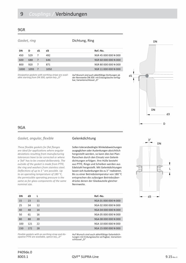
9 Couplings / Verbindungen
QVF® SUPRA-Line 9.15-Rev. 0
P409de.08003.1
Gasket, ring Dichtung, Ring
9GR
DN DD d1 d3 Ref.-No.
450450 529529 77 492492 9GR 45 000 000 N 0009GR 45 000 000 N 000
600600 688688 77 646646 9GR 60 000 000 N 0009GR 60 000 000 N 000
800800 920920 77 871871 9GR 80 000 000 N 0009GR 80 000 000 N 000
10001000 10931093 77 10501050 9GR 11 000 000 N 0009GR 11 000 000 N 000
Dissipative gaskets with earthing stripe are avail-Dissipative gaskets with earthing stripe are avail-able starting from DN 300, option key „D“able starting from DN 300, option key „D“
Auf Wunsch sind auch ablei# ähige Dichtungen ab der Nennweite DN 300 mit Erdungslasche verfüg-bar, Variantenschlüssel „D“
d1
d3
D
DN
DN
DN d3d3 L Ref.-No.
1515 2323 1111 9GA 01 000 000 N 0009GA 01 000 000 N 000
2525 3434 1212 9GA 02 000 000 N 0009GA 02 000 000 N 000
4040 4848 1414 9GA 04 000 000 N 0009GA 04 000 000 N 000
5050 6161 1616 9GA 05 000 000 N 0009GA 05 000 000 N 000
8080 8888 2020 9GA 08 000 000 N 0009GA 08 000 000 N 000
100100 121121 2222 9GA 10 000 000 N 0009GA 10 000 000 N 000
150150 172172 2828 9GA 15 000 000 N 0009GA 15 000 000 N 000
9GA
These � exible gaskets for � at � anges are ideal for applica� ons where angular devia� ons resul� ng from manufacturing tolerances have to be corrected or where a ‘fall’ has to be created deliberately. The outside of the gasket is made from PTFE, the ring and washers from stainless steel. De� ec� ons of up to 3 ° are possible. Up to an opera� ng temperature of 180 °C, the permissible opera� ng pressure is the same as for glass components of the same nominal size.
Gasket, angular, � exible Gelenkdichtung
Sollen toleranzbedingte Winkelabweichungen ausgeglichen oder Auslenkungen absichtlich hergestellt werden, so kann dies bei Plan-� anschen durch den Einsatz von Gelenk-dichtungen erfolgen. Ihre Hülle besteht aus PTFE, Ringe und Scheiben werden aus Edelstahl hergestellt. Mit Gelenkdichtungen lassen sich Auslenkungen bis zu 3 ° realisieren. Bis zu einer Betriebstemperatur von 180 °C entsprechen die zulässigen Betriebsüber-drücke denen der Glasbauteile gleicher Nennweite.
3°
L
d3
DN
Flexible gaskets with an earthing strap and dis-Flexible gaskets with an earthing strap and dis-sipative PTFE are available, option key „D“sipative PTFE are available, option key „D“
Auf Wunsch sind auch ablei# ähige Gelenkdich-tungen mit Erdungslasche verfügbar, Varianten-schlüssel „D“

9 Couplings / Verbindungen
9.16-Rev. 0 3003.1QVF®SUPRA-Line
9BW
Bellows compensate expansion and contrac� on due to changes in temperature and ensure stress-free connec� on to components made of other materials. Ball and socket pipelines can be installed with nearly no bellow, due to an appropriate plant design. The described bellows are made to � t a � at glass end or � anges of other materials. By use of a s� � ening tube the bellows star� ng with DN 80 can be used at full vacuum even at 160°C product temperature. Please Order coupling units “9CB...” for each side separately. To connect the bellow to glass lined necks use the adaptor plate “9AB...”.The adjustment of the lock nuts must be made according to the design plan. Flanges and the connec� ng material is made from stainless steel. In case of possible electrosta� c charge caused by nonconduc� ve liquid inside the bellow it can be supplied with dissipa� ve PTFE (Op� on key “D”). The rela� onship between permissible opera� ng pressure and temperature for the various types of bellows is indicated in the tables below.
Bellows Faltenbälge
Faltenbälge dienen der Kompensa� on von temperaturbedingten Längenänderungen und zum spannungsfreien Anschluss von Komponenten aus anderen Werksto� en.
Kugel/Pfanne-Rohrleitungen können durch geeignete Rohrleitungsführung nahezu ohne Faltenbälge spannungsfrei installiert werden, so dass nachfolgend nur Faltenbälge zum Anschluss an plane Rohrenden und Fremdmaterialien beschrieben werden.
Durch die Verwendung einer Vakuumstütze können die Faltenbälge ab DN 80 auch bis 160 °C Betriebstemperatur für volles Vakuum zugelassen werden.
Zum Anschluss sind geeignete Anschluss-verbindungen „9CB...“ für jede Seite zu be-stellen. Beim Anschluss an Emaille-Stutzen sind Zwischenpla� en „9AB...“ erforderlich.
Die Einstellung der Stoppschraube ist gem. den Angaben in der Anlagenzeichnung vorzunehmen.
Die Flansche und Verbindungselemente bestehen aus Edelstahl. Bei der Gefahr der elektrosta� schen Au� adung durch nicht leitende Flüssigkeiten kann der Faltenbalg mit ablei# ähigem PTFE geliefert werden (Variantenschlüssel „D“).
Die Abhängigkeit des zulässigen Betriebs-überdruckes von der Temperatur für die unterschiedlichen Ausführungen der Falten-bälge kann den nachstehenden Tabellen entnommen werden.
Spare parts / Ersatzteile Ref.-No.
PTFE bellow glass/glass / PTFE-Balg Glas/Glas 9BW ?? 000 100 N 001
PTFE bellow glass/EN&ANSI / PTFE-Balg Glas/EN&ANSI 9BW ?? 000 200 N 0019BW ?? 000 200 N 001
Stiffening tubeStiffening tube / Vakuumstütze 9BW ?? 000 150 N 012
Spare parts bellows 9BW... Ersatzteile Faltenbälge 9BW...
Die PTFE-Bälge und Vakuumstützen können bei Verschleiß leicht ausgetauscht werden.
PTFE bellows and s� � ening tubes can be replaced easyly in case of abrasion.
Dissipative PTFE, option key :“D“Dissipative PTFE, option key :“D“ Ablei# ähiges PTFE, Variantenschlüssel: „D“

9 Couplings / Verbindungen
QVF® SUPRA-Line 9.17-Rev. 0
P409de.08003.1
DN 20°C20°C9BW100/200/300Without s� ening tube/ohne Vakuum-stützebar g / bar ü
100°C9BW100/200/300Without s� ening tube/ohne Vakuum-stützebar g/ bar
160°C9BW100/200/300Without s� e-ning tube/ohne Vakuumstützebar g/ bar
160°C9BW150/250/350 With s� eningtube/mit Vakuumstützebar g/ bar
1515 -1/+4-1/+4 -1/+3-1/+3 -1/+1,5-1/+1,5 --
2525 -1/+4-1/+4 -1/+3-1/+3 -1/+1,5-1/+1,5 --
4040 -1/+4-1/+4 -1/+3-1/+3 -1/+1,5-1/+1,5 --
5050 -1/+4-1/+4 -1/+2-1/+2 -1/+1-1/+1 --
8080 -1/+3-1/+3 -1/+2-1/+2 0/+1 0/+1 -1/+1-1/+1
100100 -1/+2-1/+2 -1/+2-1/+2 0/+1 0/+1 -1/+1-1/+1
150150 -1/+2-1/+2 -1/+1,5-1/+1,5 0/+0,7 0/+0,7 -1/+0,7-1/+0,7
200200 -1/+1-1/+1 -1/+1-1/+1 0/+0,5 0/+0,5 -1/+0,5-1/+0,5
300300 -1/+1-1/+1 -1/+0,7-1/+0,7 0/+0,3 0/+0,3 -1/+0,3-1/+0,3
9BW...100
DN L1) �L D K nxd1 d2 Ref.-No.
15 35 ± 3 80 50 3xM6 23 9BW 01 000 100 N 000
25 43 ± 3 105 70 3xM8 34 9BW 02 000 100 N 000
40 52 ± 4 130 86 3xM8 48 9BW 04 000 100 N000
50 50 ± 5 150 98 3xM8 61 9BW 05 000 100 N 000
80 68 ± 6 190 134 6xM8 88 9BW 08 000 ??? N 000
100 70 ± 6 210 178 6xM8 121 9BW 10 000 ??? N 000
150 73 ± 6 280 254 6xM8 172 9BW 15 000 ??? N 000
200 73 ± 6 345 295 8xM8 220 9BW 20 000 ??? N 000
300 73 ± 6 460 400 12xM8 321 9BW 30 000 ??? N 000
StandardStandard 100100
Glass/glass with s� � ening tube / Glas/Glas mit Vakuumstütze (DN80 - DN300) 150150
Design key
1) Due to the s� � ening tube as an op� on the length of the bellow is enlarged by 6 mm.
Bellow glass/glass Faltenbalg Glas/Glas
1) Durch die op� onale Verwendung einer Vakuum-stütze verlängert sich das Einbaumaß um 6 mm.
D
K
d2
DN
d1
L
DN
Opera� ng condi� ons Betriebsbedingungen
Ausführungsschlüssel
Bei der maximal zulässigen Betriebstempera-tur von 200 °C eignen sie sich nur noch für einen drucklosen Einsatz.
If used at the maximum permissible opera� ng temperature of 200 °C, they are only suitable for use without any internal over pressure.
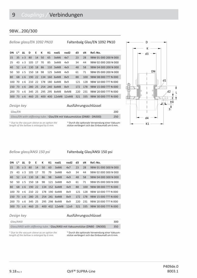
9 Couplings / Verbindungen
9.18-Rev. 0 QVF® SUPRA-LineP409de.0
8003.1
9BW...200/300
DN L1) �L D E K K1 nxd1 nxd2 d3 d4 Ref.-No.Ref.-No.
15 35 ± 3 80 14 50 65 3xM6 4x7 23 28 9BW 01 000 200 N 0009BW 01 000 200 N 000
25 43 ± 3 105 17 70 85 3xM8 4x9 34 44 9BW 02 000 200 N 0009BW 02 000 200 N 000
40 52 ± 4 130 18 86 110 3xM8 4x9 48 58 9BW 04 000 200 N 0009BW 04 000 200 N 000
50 50 ± 5 150 18 98 125 3xM8 4x9 61 71 9BW 05 000 200 N 0009BW 05 000 200 N 000
80 68 ± 6 190 22 134 160 6xM8 8x9 88 100 9BW 08 000 ??? N 0009BW 08 000 ??? N 000
100 70 ± 6 210 22 178 180 6xM8 8x9 121 128 9BW 10 000 ??? N 0009BW 10 000 ??? N 000
150 73 ± 6 280 25 254 240 6xM8 8x9 172 178 9BW 15 000 ??? N 0009BW 15 000 ??? N 000
200 73 ± 6 345 25 295 295 8xM8 8xM8 220 231 9BW 20 000 ??? N 0009BW 20 000 ??? N 000
300 73 ± 6 460 25 400 400 12xM8 12xM8 321 335 9BW 30 000 ??? N 0009BW 30 000 ??? N 000
Glas/EN Glas/EN 200200
Glass/EN with s� � ening tube / Glas/EN mit Vakuumstütze (DN80 - DN300) 250250
1) Due to the vacuum sleeve as an op� on the length of the bellow is enlarged by 6 mm.
1) Durch die op� onale Verwendung einer Vakuum-stütze verlängert sich das Einbaumaß um 6 mm.
DN L1) �L D E K K1 nxd1 nxd2 d3 d4 Ref.-No.
15 35 ± 3 80 14 50 60 3xM6 4x7 23 28 9BW 01 000 300 N 000
25 43 ± 3 105 17 70 79 3xM8 4x9 34 44 9BW 02 000 300 N 000
40 52 ± 4 130 18 86 98 3xM8 4x9 48 58 9BW 04 000 300 N 000
50 50 ± 5 150 18 98 121 3xM8 4x9 61 71 9BW 05 000 300 N 000
80 68 ± 6 190 22 134 152 6xM8 4x9 88 100 9BW 08 000 ??? N 000
100 70 ± 6 210 22 178 190 6xM8 8x9 121 128 9BW 10 000 ??? N 000
150 73 ± 6 280 25 254 241 6xM8 8x9 172 178 9BW 15 000 ??? N 000
200 73 ± 6 345 25 295 298 8xM8 8x9 220 231 9BW 20 000 ??? N 000
300 73 ± 6 460 25 400 432 12xM8 12x9 321 335 9BW 30 000 ??? N 000
Glas/ANSI 300300
Glass/ANSI with s� � ening tube / Glas/ANSI mit Vakuumstütze (DN80 - DN300) 350
1) Due to the vacuum sleeve as an op� on the length of the bellow is enlarged by 6 mm.
1) Durch die op� onale Verwendung einer Vakuum-stütze verlängert sich das Einbaumaß um 6 mm.
Bellow glass/EN 1092 PN10 Faltenbalg Glas/EN 1092 PN10
Bellow glass/ANSI 150 psi Faltenbalg Glas/ANSI 150 psi
Design key Ausführungsschlüssel
Design key Ausführungsschlüssel

9 Couplings / Verbindungen
QVF® SUPRA-Line 9.19-Rev. 0
P409de.08003.1
This type of bellows can be used at temperatures of up to 200 °C under vacuum and posi� ve pressure corresponding to the maximum working pressure of the equivalent glass pipe diameter. Standard design of the bellows are made of white PTFE and equipped with galvanized-steel � anges. Both � anges have threaded holes on a graduated circle according to EN1092 PN10.Connec� on to glassThe connec� on of glass components is done using an adaptor kit “9CB…” which contains a PTFE-coated stainless steel adaptor plate a� ached to the bellows � ange, plus the � ange ring, the insert and the connec� ng hardware for connec� on of the glass joint.
Addi� onal gaskets are not required.
Connec� on to enamelA seal is required here. We recommend our corrugated PTFE gasket. The connec� on is made with the screw diameters and � ghtening torques intended for enamel � anges.
Diese Ausführung ist bei Temperaturen bis 200 °C sowohl im Vakuumbereich als auch im Überdruckbereich, entsprechend der zulässigen Betriebsüberdrücke der Glasbau-teile, einsetzbar.
Die Bälge bestehen in der Standardausführung aus weißem PTFE und sind mit Flanschen aus verzinktem Stahl versehen. Beide Flansche sind mit Gewindebohrungen auf einem Teilkreis nach EN1092 PN10 ausgesta� et.
Anschluss an GlasDer Anschluss an Glasbauteile erfolgt mit einem Anbausatz „9CB…“. Dieser besteht aus einer PTFE-ummantelten Edelstahl-Zwischenplatte, die mit dem Falten-balg� ansch verschraubt wird, sowie dem Flanschring, der Beilage und den Ver-bindungselementen zum Anschluss des Glas� ansches.
Zusätzliche Dichtungen sind nicht erforder-lich.
Anschluss an Emaille Hier ist eine Dichtung erforderlich. Wir empfehlen unsere PTFE-Wellringdichtung. Der Anschluss erfolgt mit den für Emaille-� ansche vorgesehenen Schraubendurch-messern und Anzugsmomenten.
Bellow, heavy Faltenbalg, schwer
9BH
DN DD L Lmin Lmax K nxd2 Ref.-No.
25 163 54 45 63 85 4xM12 9BH 02 000 000 N 000
40 204 58 45 71 110 4xM16 9BH 04 000 000 N 000
50 219 69 54 84 125 4xM16 9BH 05 000 000 N 000
80 267 78 62 94 160 8xM16 9BH 08 000 000 N 000
100 287 96 76 116 180 8xM16 9BH 10 000 000 N 000
150 270 108 83 133 240 8xM20 9BH 15 000 000 N 000
200 460 137 109 165 295 8xM20 9BH 20 000 000 N 000
300 690 115 97 133 400 12xM20 9BH 30 000 000 N 000
L
DK
d1

9 Couplings / Verbindungen
9.20-Rev. 0 QVF® SUPRA-LineP409de.0
8003.1
9CB
Glass to standard bellow / Glas an standard Faltenbalg
Glas to s� ening tube / Glas an Vakuumstütze
Glass to bellow, heavy / Glas an Faltenbalg, schwer
DN Ref.-No. Type A Ref.-No. Type A Ref.-No. Type B L
1515 9CB 01 000 100 E 0009CB 01 000 100 E 000 -- -- --
2525 9CB 02 000 100 E 0009CB 02 000 100 E 000 -- 9CB 02 000 600 N 0009CB 02 000 600 N 000 1212
4040 9CB 04 000 100 E 0009CB 04 000 100 E 000 -- 9CB 04 000 600 N 0009CB 04 000 600 N 000 1414
5050 9CB 05 000 100 E 0009CB 05 000 100 E 000 -- 9CB 05 000 600 N 0009CB 05 000 600 N 000 1414
8080 9CB 08 000 100 E 0009CB 08 000 100 E 000 9CB 08 000 400 E 0009CB 08 000 400 E 000 9CB 08 000 600 N 0009CB 08 000 600 N 000 1414
100100 9CB 10 000 100 E 0009CB 10 000 100 E 000 9CB 10 000 400 E 0009CB 10 000 400 E 000 9CB 10 000 600 N 0009CB 10 000 600 N 000 1414
150150 9CB 15 000 100 E 0009CB 15 000 100 E 000 9CB 15 000 400 E 0009CB 15 000 400 E 000 9CB 15 000 600 N 0009CB 15 000 600 N 000 1717
200200 9CB 20 000 100 E 0009CB 20 000 100 E 000 9CB 20 000 400 E 0009CB 20 000 400 E 000 9CB 20 000 600 N 0009CB 20 000 600 N 000 1919
300300 9CB 30 000 100 E 0009CB 30 000 100 E 000 9CB 30 000 400 E 0009CB 30 000 400 E 000 9CB 30 000 600 N 0009CB 30 000 600 N 000 1919
Verbindung für Faltenbälge Verbindung für Faltenbälge Coupling for bellowsCoupling for bellows
The coupling unit consists of coupling parts for one glass end including � ange ring, insert, silicon shim, spring element and nuts and bolts.
Die Verbindungen enthalten die Flanschringe, Unterlagen, Beilagen, Schrauben und Federn, die zum Anschluss einer Faltenbalgseite an den Glas� ansch erforderlich sind.
9AB
This gasket is used as interface between PTFE-bellows with machined sealing ring and glass lined necks.
Adaptor plate, bellows/glass lining
Anschlusspla� e, Faltenbalg/Emaille
Zum Anschluss von Faltenbälgen mit ange-drehter Dichtung an Emaille-Flansche.
DN DN1 D d1 d4 L Ref.-No.
25 25 68 23 48 9 9AB 02 002 000 N 000
40 321)/40 78 36 70 9 9AB 04 004 000 N 000
50 50 102 50 89 9 9AB 05 005 000 N 000
80 651)/80 125 78 111 11 9AB 08 008 000 N 000
100 100 158 100 140 11 9AB 10 010 000 N 000
150 150 214 150 195 12 9AB 15 015 000 N 000
200 200 269 200 246 12 9AB 20 020 000 N 000
300 300 370 300 345 12 9AB 30 030 000 N 000
1) Only for EN FlangesDissipative PTFE, option key :“D“Dissipative PTFE, option key :“D“
1) nur für EN-FlanscheAblei# ähiges PTFE, Variantenschlüssel: „D“
L
BDN

9 Couplings / Verbindungen
QVF® SUPRA-Line 9.21-Rev. 0
P409de.08003.1
9AE
This gasket is used as interface between a plane glass end and a glass lined steel � ange. It comprises a stainless steel disc made from 1.4301 and a PTFE envelope.
Adaptor plate, glass/enamel Anschlusspla� e, Glas/Emaille
Zum Anschluss von Plan� anschbauteilen an emaillierte Stahl� ansche wird diese Über-gangsdichtung aus PTFE mit Stützscheibe aus Edelstahl 1.4301 verwendet.
DN DN1 D d1 d3 d4 L Ref.-No.
25 25 68 23 34 48 9 9AE 02 002 000 N 000
40 321)/40 78 36 48 70 10 9AE 04 004 000 N 000
50 50 102 50 61 89 10 9AE 05 005 000 N 000
80 651)/80 125 78 88 111 13 9AE 08 008 000 N 000
100 100 158 100 121 140 13 9AE 10 010 000 N 000
150 150 214 150 172 195 15 9AE 15 015 000 N 000
200 200 269 200 220 246 15 9AE 20 020 000 N 000
200 250 322 200 220 297 18 9AE 20 025 000 N 000
300 300 370 300 321 349 18 9AE 30 030 000 N 000
1) Only for EN Flanges Dissipative PTFE,Option Dissipative PTFE,Option key :“D“key :“D“
1) nur für EN-FlanscheAblei# ähiges PTFE, Variantenschlüssel: „D“

9 Couplings / Verbindungen
9.22-Rev. 0 QVF® SUPRA-LineP409de.0
8003.1
The hoses are made of PTFE shrunk onto a borosilicate glass 3.3 hose connector at each end and � xed with a special stainless steel clamp. All spiral hoses can be used under vacuum to an absolute pressure of 1 mbar at a opera� ng temperature of 180 °C. The permissible opera� ng pressure as a func� on of temperature is indicated in the table below. Above 120 °C working temperature no overpressure is allowed.
Die Spiralschläuche aus PTFE sind beidsei� g auf ein Anschlussstück aus Borosilicatglas 3.3 aufgeschrump� und mit einer Edelstahl-schelle befes� gt. Alle Spiralschläuche sind vakuumfest und können bis zu einem Absolutdruck von 1 mbar bei einer Betriebs-temperatur von 180 °C eingesetzt werden. Die zulässigen Betriebsüberdrücke in Ab-hängigkeit von der Temperatur können Sie der nachstehenden Tabelle entnehmen. Ab einer Betriebstemperatur von 120 °C ist der Schlauch nur noch drucklos einzusetzen.
Hose, product Schlauch, Produkt
9HP
DN d L Bend radius min /Biegeradius min
Pmax [bar g / bar]20 °C 100 °C
Ref.-No.
DN15 10 500 50 4 0,5 9HP 01 050 330 N 000
DN15 10 1000 50 4 0,5 9HP 01 100 330 N 000
DN15 10 2000 50 4 0,5 9HP 01 200 330 N 000
DN25 20 500 85 4 0,5 9HP 02 050 330 N 000
DN25 20 1000 85 4 0,5 9HP 02 100 330 N 000
DN25 20 2000 85 4 0,5 9HP 02 200 330 N 000
DN40 35 500 120 2,5 0,5 9HP 04 050 330 N 000
DN40 35 1000 120 2,5 0,5 9HP 04 100 330 N 000
DN40 35 2000 120 2,5 0,5 9HP 04 200 330 N 000

9 Couplings / Verbindungen
QVF® SUPRA-Line 9.23-Rev. 0
P409de.08003.1
Der zulässige Betriebsüberdruck der Schläuche beträgt 16 bar, ihre zulässige Betriebstemperatur -30/+300 °C. Die zulässigen Betriebsbedingungen der angeschlossenen Komponenten sind zu beachten.
Eine komple� e Verbindung aus Edelstahl einschließlich Dichtung für den Anschluss an den Glasstutzen gehört zum Lieferumfang.
Hose, service, glass/EN 1092 PN10The permissible maximum opera� ng pressure for these hoses is 16 bar g and the permissible opera� ng temperature is -30/+300 °C. The permissible opera� ng condi� ons for the components to which they are connected should also be taken into account.One end is � � ed with a stainless steel loose � ange and gasket for ease of assembly.
Schlauch, Service, Glas/EN 1092 PN10
9HS
DN DN1 L K nxd E Ref.-No.25 25 1000 85 4x14 16 9HS 02 100 000 N 000
Der Bügelverschluss ist mit einem schwenk-baren Bügel ausgesta� et und wird über die daran befes� gte Spindel mit Handrad zentral gespannt. Flanschring, Deckel, Bügel und Klappschrauben bestehen aus Edel-stahl. Der Deckel ist produktsei� g mit einer PTFE-Pla� e verkleidet und der ebenfalls korrosionsbeständige O-Ring liegt in einer hinterdrehten Nut. Der zulässige Betriebs-überdruck der Bügelverschlüsse beträgt -1 bis +0,6 bar, wenn die Apparatur ein örtliches Manometer besitzt.
Zulässige Betriebstemperatur TS: -15°C bis +200°C
They have a swivelling bracket and are closed by means of a spindle a� ached to a centrally located hand-wheel. The � ange, cover, bracket and hinged bolts are stainless steel. The cover is faced with a PTFE disc on the product side and a corrosion resistant O-ring which is located in a recessed groove. The permissible opera� ng overpressure of the shackle closure is -1 to +0.6 bar, if the unit is equipped with a local pressure gauge.Permissible working temperature TS:-15°C up to +200°C
Bügelverschluss
DN D H Ref.-No.5050 150 140140 9SC 05 000 000 N 0009SC 05 000 000 N 000
8080 190 155155 9SC 08 000 000 N 0009SC 08 000 000 N 000
100100 210210 185185 9SC 10 000 000 N 0009SC 10 000 000 N 000
150150 280 215215 9SC 15 000 000 N 0009SC 15 000 000 N 000
Shackl closure
9SC

9 Couplings / Verbindungen
9.24-Rev. 0 QVF® SUPRA-LineP409de.0
8003.1
In this case, the couplings comprise two stainless steel rings with a PTFE sheath, two � anges with inserts and the appropriate quan� ty of stainless steel reducing washers, set screws, compression springs and nuts.
In diesem Fall bestehen die Anbausätze aus zwei Edelstahlringen mit U-förmiger Hülle aus PTFE, zwei Flanschringen mit Einlage sowie den erforderlichen Reduzierhülsen, Schrauben, Druckfedern und Mu� ern aus Edelstahl.
Adaptor set, for bu� er� y valves, glass/glass
Anbausatz, für Klappen, Glas/Glas
9AS...100
DN L D K nxd Ref.-No.50 70 165 125 4xM8 9AS 05 000 100 N 000
80 74 200 160 8xM8 9AS 08 000 100 N 000
100 80 220 180 8xM8 9AS 10 000 100 N 000
150 88 285 240 8xM8 9AS 15 000 100 N 000
200 96 345 295 8xM8 9AS 20 000 100 N 000
300 115 460 400 12xM8 9AS 30 000 100 N 000
DN L D K K1 nxd nxd2 Ref.-No.50 57 165 125 125125 4xM8 4x11 9AS 05 000 200 N 000
80 60 200 160 160 8xM8 8x11 9AS 08 000 200 N 000
100 66 220 180 180 8xM8 8x11 9AS 10 000 200 N 000
150 72 285 240 240 8xM8 8x13 9AS 15 000 200 N 000
200 78 340 295 295 8xM8 8x13 9AS 20 000 200 N 000
300 96 450 400 400 12xM8 8x13 9AS 30 000 200 N 000
Couplings for this applica� on comprise one stainless steel ring with a PTFE sheath, one � ange with insert and the appropriate quan� ty of stainless steel reducing washers, set screws, compression springs and nuts.
Adaptor set, for bu� er� y valves, glass / EN 1092 PN10
Anbausatz, für Klappen, Glas /EN 1092 PN10Anbausätze für diesen Anwendungsfall bestehen aus einem Edelstahlring mit U-förmiger Hülle aus PTFE, einem Flanschring mit Einlage sowie den erforderlichen Reduzierhülsen, Schrauben, Druckfedern und Mu� ern aus Edelstahl.
9AS...200

P410e.08003.1
������������� �������
2. Pipeline Components
3. Valves and Filters
4. Vessels
5. Heat Exchangers
6. Column Components
������������
8. Measurement and Control
9. Couplings
10. STRUCTURES AND SUPPORTS
The Component System

10 Structures & Supports / Gestelle & Halterungen
10.2-Rev. 0 QVF® SUPRA-LineP410de.0
8003.1
Contents / Inhaltsverzeichnis
Ref.-No. Reference Ar� kel-Bezeichnung Page / Seite
0ST Structure tubing Gestellrohr 7
0SF Structure � � ng, closed Gestellrohrverbinder, geschlossen 8
0SF Structure � � ng, open Gestellrohrverbinder, o� en 9
0SB Structure bushes Rohrrahmenrundmu� ern 10
0SS Support stool Pro� lstahlunterbau 10
0TF Tube frame Rohrrahmen 11
0VR Vesselholder for spherical vessel Tragschale für Kugelgefäß 12
0VR Vesselholder for cylindrical vessel, receiver Tragschale für Zylindergefäß, zugezogen 12
0AB Angled support bracket, stainless steel Tragwinkel, Edelstahl 13
0SS Support saddle Tragsa� el 13
0PB Pipe bracket Halteklauen 14
0PS Pipe support Rohrhalter 15
0PH Pipe hanger Rohrschelle 16
0PC Protec� ve cover Schutzwand 17
Technical data are subject to change. All rights reserved. Copyright © De Dietrich Process Systems GmbH.
Technische Änderungen und Irrtümer vor-behalten. Copyright © De Dietrich Process Systems GmbH.

10 Structures & Supports / Gestelle & Halterungen
10.3-Rev. 0QVF® SUPRA-LineP410de.08003.1
QVF® SUPRA-Line Reference No.
Ar� cles of the QVF® SUPRA-Line component system are de� ned by a reference code of 15 characters. The code is led by the number of the catalogue sec� on and 2 le� ers linked to the English descrip� on.All other characters are used to specify the ar� cle in its group. The remaining posi� ons are � lled with “0”.In case a reference number has to be com-pleted a “?” is shown. The right number is indicated in the op� on key table of the cata-logue sec� on or the ar� cle group itself.Free space between the reference segments is not a part of the reference number it is only set to read the number easily.
QVF® SUPRA-Line Ar� kelnummern
Die Ar� kel des neuen QVF® SUPRA-Line Bauteileprogramms werden über eine 15-stellige Ar� kelnummer de� niert. Das 1. Segment - die Ar� kelgruppe - besteht aus der Kapitelzi� er und zwei Buchstaben die aus der englischen Bezeichnung des Ar� kels abgeleitet sind.
Alle weiteren Segmente dienen zur Di� eren-zierung der Ar� kel innerhalb einer Ar� kel-gruppe. Nicht benö� gte Stellen werden mit 0 aufgefüllt.
Zu ergänzende Stellen sind mit „?“ gekenn-zeichnet. Die wählbaren Bauteil-A� ribute sind ar� kelbezogen in einer Code-Tabelle aufgeführt.
Leerzeichen zwischen den einzelnen Segmenten dienen der besseren Lesbarkeit und sind kein Bestandteil der Ar� kelnummer.
Option key Section 10Option key Section 10 Variantenschlüssel Kapitel 10Variantenschlüssel Kapitel 10
N No op� on / Standard
E stainless steel / Edelstahl
B Blue coated / blau beschichtet
S Steel galvanised / Stahl verzinkt
Ar� cle group / Ar� kelschlüssel
Nominal diameter key / Nennweitenschlüssel
Design key 1 / Ausführungsschlüssel 1
Design key 2 / Ausführungsschlüssel 2
Op� on key / Variantenschlüssel
Sub item / Unterposi� on
0AA 00 000 000 A 000

10 Structures & Supports / Gestelle & Halterungen
10.4-Rev. 0 QVF® SUPRA-LineP410de.0
8003.1
QVF® structures are designed to support plant and other equipment comprising components exclusively or principally in borosilicate glass 3.3. Basically these structures consist of steel tubing in three di� erent diameters which is connected using the appropriate � � ngs. As a result, the structures can not only be dismantled and reassembled whenever required but they can also be modi� ed and added to quite easily.
Enhanced purity speci� ca� onsThe standard structure is made of elements with galvanised � nish, which is appropriate for most of the produc� on surroundings. For applica� ons where galvanised elements are not requested, we supply epoxy coated clamps and adequate polished stainless steel tubes.
Design of tubular structures
The diameter of the structure tubing and minimum over all dimension of the structure to be used are determined by the nominal size or diameter and the weight of the components they are designed to support. Details can be found in the table below. In case of high total weight we recommend to use a heavy duty base structure.Glass units and their structures expand at di� erent rates as a result of change in temperature. The unit must, therefore, be able to expand above the � xed point without restraint. If there is the risk of vibra� on generated in the vicinity of glass units being transferred to the tubular structure, appropriate preven� ve measures should be taken.
General Allgemeines
QVF®-Gestellbau dient der Aufstellung von Apparaturen und Anlagen aus Borosilicatglas 3.3. Die Grundelemente dieses Baukastensystems bilden Metallrohre in drei unterschiedlichen Durchmessern, die über Gestellrohrver-binder miteinander verbunden werden. Dadurch besteht nicht nur die Möglichkeit, die Gestelle jederzeit demon� eren und wieder au$ auen zu können, sondern auch Änderungen und Ergänzungen lassen sich an ihnen problemlos vornehmen.
Erhöhte ReinheitsanforderungenDie Standardversion besteht aus verzinkten Rohren und Gestellrohrverbindern, die für die meisten Produk� onsumgebungen ge-eignet sind. Für Bereiche, in denen verzinkte Gestelle nicht erwünscht sind, liefern wir die Bauteile mit einer Epoxidharzlackierung und die entsprechenden Rohre aus poliertem Edelstahl.
Konstruk� ve Gestaltung der RohrgestelleDie zu verwendenden Gestellrohrdurch-messer sowie die Mindestmaße von Rohrgestellen werden von der Nennweite bzw. dem Durchmesser der darin zu montierenden Komponenten und deren Gewichten bestimmt.
Nähere Angaben hierzu � nden Sie in nachstehender Tabelle. Für hohe Gewichte empfehlen wir die Verwendung eines Pro� lstahl-Unterbaus.
Rohrgestell und Glasapparatur dehnen sich unter Temperaturein� uss unterschiedlich aus. Letztere muss sich daher vom Fest-punkt aus ungehindert ausdehnen können.
Besteht die Gefahr, dass im Umfeld von Glasanlagen erzeugte Schwingungen auf das Rohrgestell übertragen werden können, so ist dies durch geeignete Maßnahmen zu verhindern.

10 Structures & Supports / Gestelle & Halterungen
10.5-Rev. 0QVF® SUPRA-LineP410de.08003.1
Support structures must be su� ciently rigid to prevent any bending of the individual tubes in excess of the permissible extend and the subsequent transfer of external stress to the glass components. For rigidity at least two adjacent sides of the structure should be provided with diagonal bracing. In addi� on, tall structures should be braced back to exis� ng structural steelwork or the walls of the building.The design of � xed points is of par� cular importance. Fixed points have to carry the weight of a unit or column and should therefore be located at the lowest possible point in the installa� on. As � xed points either vessel holders for spherical vessels and receivers or tube frames of the nominal diameter for cylindrical vessles and columns are available.The assembly of the glass components must always be started from � xed points.
Structure dimension, � xed points
Colums & vessels / Colums & vessels / Kolonnen & ZylindergefäßeDN
Spherical vessels / Kugelnl
Vessel, receiver /Vorlagegefäß DN
Vessel holder / Tragschalen
Tube frame / Rohrrahmen
Tube Ø /Rohr Ømm
Structure / Structure / Gestell Lmm
8080 -- -- -- 0TF 27 008 000 S 0000TF 27 008 000 S 000 2727 400400
100100 -- -- -- 0TF 27 010 000 S 0000TF 27 010 000 S 000 2727 500500
150150 -- -- -- 0TF 27 015 000 S 0000TF 27 015 000 S 000 2727 600600
150150 -- -- -- 0TF 42 015 000 S 0000TF 42 015 000 S 000 4242 600600
200200 -- -- -- 0TF 42 020 000 S 0000TF 42 020 000 S 000 4242 700700
300300 -- -- -- 0TF 42 030 000 S 0000TF 42 030 000 S 000 4242 800800
450450 -- -- -- 0TF 42 045 000 S 0000TF 42 045 000 S 000 4242 10001000
600600 -- -- -- 0TF 42 060 000 S 0000TF 42 060 000 S 000 4242 11001100
800800 -- -- -- 6060 1600/15101600/1510
10001000 -- -- -- 6060 1930/16801930/1680
-- 55 -- 0VR 00 005 000 E 0000VR 00 005 000 E 000 0TF 27 015 000 S 0000TF 27 015 000 S 000 2727 600600
-- 1010 -- 0VR 00 010 000 E 0000VR 00 010 000 E 000 0TF 42 015 000 S 0000TF 42 015 000 S 000 4242 600600
-- 2020 -- 0VR 00 020 000 E 0000VR 00 020 000 E 000 0TF 42 020 000 S 0000TF 42 020 000 S 000 4242 700700
-- 5050 450450 0VR 00 050 000 B 0000VR 00 050 000 B 000 0TF 42 030 000 S 0000TF 42 030 000 S 000 4242 800800
-- 100100 600600 0VR 00 100 000 B 0000VR 00 100 000 B 000 0TF 42 030 000 S 0000TF 42 030 000 S 000 4242 10001000
-- 200200 -- 0VR 00 200 000 B 0000VR 00 200 000 B 000 0TF 42 045 000 S 0000TF 42 045 000 S 000 4242 11001100
-- 500500 -- 0VR 00 500 000 B 0000VR 00 500 000 B 000 4242 11001100
Rohrgestellmaße, Festpunkte
Vesselholder / Tragschale
Tube frame / Rohrrahmen
Rohrgestelle müssen so steif ausgeführt werden, dass die Durchbiegung der Einzel-rohre den zulässigen Wert nicht über-schreitet und keine äußeren Krä� e auf die Glasbauteile übertragen werden können.
Zur Versteifung sind mindestens zwei rechtwinklig zueinander angeordnete Seiten eines Rohrgestells mit Diagonalen zu versehen. Höhere Gestelle sollten zusätz-lich an vorhandenen Bühnen oder Gebäude-wänden abgefangen werden.
Eine besondere Bedeutung kommt der Gestaltung von Festpunkten zu. Festpunkte haben das Gewicht einer Apparatur oder Kolonne aufzunehmen und sind daher an einem möglichst � ef gelegenen Punkt der Installa� on anzuordnen. Als Festpunkt für Kugeln und Vorlage-Zylindergefäße werden Tragschalen verwendet, für Kolonnen und Zylindergefäße Rohrrahmen der gleichen Nennweite.
Mit der Montage der Glasbauteile muss immer am Festpunkt begonnen werden.

10 Structures & Supports / Gestelle & Halterungen
10.6-Rev. 0 QVF® SUPRA-LineP410de.0
8003.1
Sowohl horizontale als auch ver� kale Rohr-leitungen müssen in bes� mmten Abständen gehaltert werden. Richtwerte für die maximal zulässigen Stützweiten horizontaler Rohrleitungen in Abhängigkeit von deren Nennweite sind der nachstehenden Tabelle zu entnehmen.
Both horizontal and ver� cal pipelines must be supported at certain intervals. The recommended spacing of horizontal pipeline supports as a func� on of nominal size is indicated in the table below.
Pipeline / Rohrleitung Horizontal pipeline / Maximum spacing L (mm) waagerechte Rohrleitung / Maximale Stützweite L (mm)
DN Gas =1 kg/l =1,8 kg/l1515 15001500 15001500 10001000
2525 20002000 20002000 15001500
4040 25002500 20002000 15001500
5050 25002500 20002000 15001500
8080 30003000 20002000 15001500
100100 30003000 25002500 20002000
150150 30003000 20002000 20002000
200200 30003000 20002000 15001500
300300 30003000 20002000 15001500
Suppor� ng horizontal pipeline Halterung von horizontalen Rohr-leitungen

10 Structures & Supports / Gestelle & Halterungen
10.7-Rev. 0QVF® SUPRA-LineP410de.08003.1
Zulässige Gestellrohrbelastung in Abhängig-keit von der freien Länge.
Permissible structure tubing load as a func� on of unsupported tube length.
Da die Durchbiegung der Gestellrohre 2 mm nicht überschreiten darf, ist die maximal zulässige freie Länge der Rohre von deren Belastung abhängig. Sie ermi� elt sich z.B. an einem Festpunkt als Summe der Gewichte von Rohrrahmen, Glasbauteilen einschließlich Verbindungen und Flüssig-keitsinhalt. Die Anzahl der Au� agepunkte ist dabei zu berücksich� gen.
As it is important that the structure tubing should not bow by more than 2 mm, the maximum permissible free length of the tubing depends on the load. This can be calculated, at a � xed point for example, as the sum of the weights of support framework, glass components including couplings and liquid content. The number of support points should also be taken into account.
0ST
Structure tubing Gestellrohre
Werden auf Maß zugeschni� ene Einzelrohre gewünscht, so ist die Bestell-Nr. um die Länge (in mm) zu ergänzen.
If individual lengths of tubing are required, please add the length (in mm) to the catalogue reference.
Fi ng size D / Verbindergröße D
Ref.-No. Steel / Stahl
Ref.-No. stainless steel / Edelstahl
2727 0ST 27 ??? ??? S 0000ST 27 ??? ??? S 000 0ST 27 ??? ??? E 0000ST 27 ??? ??? E 000
4242 0ST 42 ??? ??? S 0000ST 42 ??? ??? S 000 0ST 42 ??? ??? E 0000ST 42 ??? ??? E 000
6060 0ST 60 ??? ??? S 0000ST 60 ??? ??? S 000 0ST 60 ??? ??? E 0000ST 60 ??? ??? E 000
Design key Design key length of tubelength of tubeExample:Example:
Ausführungsschlüssel Ausführungsschlüssel GestellrohrlängeGestellrohrlängeBeispiel:Beispiel:
length of tube / Gestellrohrlänge 2 630 mm 002 630

10 Structures & Supports / Gestelle & Halterungen
10.8-Rev. 0 QVF® SUPRA-LineP410de.0
8003.1
Purpose / Verwendungszweck
Tube Ø /Rohr Ømm
Ref.-No.Galvanised / verzinkt
Ref.-No.blue painted / blau lackiert
Frame / Frame / GrundgestellGrundgestell
272742426060
0SF 27 010 100 S 0000SF 27 010 100 S 0000SF 42 010 100 S 0000SF 42 010 100 S 0000SF 60 010 100 S 0000SF 60 010 100 S 000
0SF 27 010 100 B 0000SF 27 010 100 B 0000SF 42 010 100 B 0000SF 42 010 100 B 0000SF 60 010 100 B 0000SF 60 010 100 B 000
Frame / Frame / GrundgestellGrundgestell
272742426060
0SF 27 014 100 S 0000SF 27 014 100 S 0000SF 42 014 100 S 0000SF 42 014 100 S 0000SF 60 014 100 S 0000SF 60 014 100 S 000
0SF 27 014 100 B 0000SF 27 014 100 B 0000SF 42 014 100 B 0000SF 42 014 100 B 0000SF 60 014 100 B 0000SF 60 014 100 B 000
Frame /Frame /GrundgestellGrundgestell
272742 42 60 60
0SF 27 015 100 S 0000SF 27 015 100 S 0000SF 42 015 100 S 0000SF 42 015 100 S 0000SF 60 015 100 S 0000SF 60 015 100 S 000
0SF 27 015 100 B 0000SF 27 015 100 B 0000SF 42 015 100 B 0000SF 42 015 100 B 0000SF 60 015 100 B 0000SF 60 015 100 B 000
Frame / Frame / GrundgestellGrundgestell
272742426060
0SF 27 021 100 S 0000SF 27 021 100 S 0000SF 42 021 100 S 0000SF 42 021 100 S 0000SF 60 021 100 S 0000SF 60 021 100 S 000
0SF 27 021 100 B 0000SF 27 021 100 B 0000SF 42 021 100 B 0000SF 42 021 100 B 0000SF 60 021 100 B 0000SF 60 021 100 B 000
Frame /Frame /GrundgestellGrundgestell
272742426060
0SF 27 026 100 S 0000SF 27 026 100 S 0000SF 42 026 100 S 0000SF 42 026 100 S 0000SF 60 026 100 S 0000SF 60 026 100 S 000
0SF 27 026 100 B 0000SF 27 026 100 B 0000SF 42 026 100 B 0000SF 42 026 100 B 0000SF 60 026 100 B 0000SF 60 026 100 B 000
Frame / Frame / GrundgestellGrundgestell
272742426060
0SF 27 035 100 S 0000SF 27 035 100 S 0000SF 42 035 100 S 0000SF 42 035 100 S 0000SF 60 035 100 S 0000SF 60 035 100 S 000
0SF 27 035 100 B 0000SF 27 035 100 B 0000SF 42 035 100 B 0000SF 42 035 100 B 0000SF 60 035 100 B 0000SF 60 035 100 B 000
Frame / Frame / GrundgestellGrundgestell
272742426060
0SF 27 040 100 S 0000SF 27 040 100 S 0000SF 42 040 100 S 0000SF 42 040 100 S 0000SF 60 040 100 S 0000SF 60 040 100 S 000
0SF 27 040 100 B 0000SF 27 040 100 B 0000SF 42 040 100 B 0000SF 42 040 100 B 0000SF 60 040 100 B 0000SF 60 040 100 B 000
Frame /Frame /GrundgestellGrundgestell
272742426060
0SF 27 045 100 S 0000SF 27 045 100 S 0000SF 42 045 100 S 0000SF 42 045 100 S 0000SF 60 045 100 S 0000SF 60 045 100 S 000
0SF 27 045 100 B 0000SF 27 045 100 B 0000SF 42 045 100 B 0000SF 42 045 100 B 0000SF 60 045 100 B 0000SF 60 045 100 B 000
Frame (reduction) /Frame (reduction) /Grundgestell (Reduzierung)Grundgestell (Reduzierung)
272742/2742/2760/4260/42
0SF 42 214 100 S 0000SF 42 214 100 S 0000SF 60 414 100 S 0000SF 60 414 100 S 000
0SF 42 214 100 B 0000SF 42 214 100 B 0000SF 60 414 100 B 0000SF 60 414 100 B 000
For diagonals / For diagonals / Für DiagonalenFür Diagonalen
27274242
0SF 27 049 100 S 0000SF 27 049 100 S 0000SF 42 049 100 S 0000SF 42 049 100 S 000
0SF 27 049 100 B 0000SF 27 049 100 B 0000SF 42 049 100 B 0000SF 42 049 100 B 000
Fix/Loose point / Fix/Loose point / Fest-/LospunktFest-/Lospunkt
27274242
0SF 27 050 100 S 0000SF 27 050 100 S 0000SF 42 050 100 S 0000SF 42 050 100 S 000
0SF 27 050 100 B 0000SF 27 050 100 B 0000SF 42 050 100 B 0000SF 42 050 100 B 000
Structure feet / Structure feet / GestellfüßeGestellfüße
272742426060
0SF 27 062 100 S 0000SF 27 062 100 S 0000SF 42 062 100 S 0000SF 42 062 100 S 0000SF 60 062 100 S 0000SF 60 062 100 S 000
0SF 27 062 100 B 0000SF 27 062 100 B 0000SF 42 062 100 B 0000SF 42 062 100 B 0000SF 60 062 100 B 0000SF 60 062 100 B 000
Replacement screws / Replacement screws / ErsatzschraubenErsatzschrauben
2727424260 60
0SF 27 097 100 S 0000SF 27 097 100 S 0000SF 42 097 100 S 0000SF 42 097 100 S 0000SF 60 097 100 S 0000SF 60 097 100 S 000
Replacement key / Replacement key / ErsatzschlüsselErsatzschlüssel
27 (¼“ BSP)27 (¼“ BSP)42 (3/8“ BSP)42 (3/8“ BSP)60 (3/8“ BSP)60 (3/8“ BSP)
0SF 27 099 100 S 0000SF 27 099 100 S 0000SF 42 099 100 S 0000SF 42 099 100 S 0000SF 60 099 100 S 0000SF 60 099 100 S 000
Plug for tube ends / Plug for tube ends / VerschlußstopfenVerschlußstopfen
2727424260 60
0ST 27 000 000 P 0000ST 27 000 000 P 0000ST 42 000 000 P 0000ST 42 000 000 P 0000ST 60 000 000 P 0000ST 60 000 000 P 000
0SF ...100
Structure � � ng, closed Gestellrohrverbinder, geschlossen

10 Structures & Supports / Gestelle & Halterungen
10.9-Rev. 0QVF® SUPRA-LineP410de.08003.1
0SF...200
Structure � � ng, open Gestellrohrverbinder, o� en
Purpose / Verwendungszweck
Tube Ø / Rohr Ømm
Ref.-No.Galvanised / verzinkt
Ref.-No.blue painted / blau lackiert
Frame /Frame /GrundgestellGrundgestell
272742426060
0SF 42 010 200 S 0000SF 42 010 200 S 000 0SF 42 010 200 B 0000SF 42 010 200 B 000
Fixed/loose point /Fixed/loose point /Fest-/LospunktFest-/Lospunkt
272742/2742/2760/2760/27
0SF 42 245 200 S 0000SF 42 245 200 S 0000SF 60 245 200 S 0000SF 60 245 200 S 000
0SF 42 245 200 B 0000SF 42 245 200 B 0000SF 60 245 200 B 0000SF 60 245 200 B 000
Fixed/loose point / Fixed/loose point / Fest-/LospunktFest-/Lospunkt
2727424260/4260/42
0SF 27 045 200 S 0000SF 27 045 200 S 0000SF 42 045 200 S 0000SF 42 045 200 S 0000SF 60 445 200 S 0000SF 60 445 200 S 000
0SF 27 045 200 B 0000SF 27 045 200 B 0000SF 42 045 200 B 0000SF 42 045 200 B 0000SF 60 445 200 B 0000SF 60 445 200 B 000
For diagonals /For diagonals /Für DiagonalenFür Diagonalen
272742426060
0SF 27 050 200 S 0000SF 27 050 200 S 0000SF 42 050 200 S 0000SF 42 050 200 S 0000SF 60 050 200 S 0000SF 60 050 200 S 000
0SF 27 050 200 B 0000SF 27 050 200 B 0000SF 42 050 200 B 0000SF 42 050 200 B 0000SF 60 050 200 B 0000SF 60 050 200 B 000
Replacement grub screws / Replacement grub screws / ErsatzschraubenErsatzschrauben
272742426060
DI916-12x16-STDI916-12x16-STDI916-16x20-STDI916-16x20-STDI916-16x20-STDI916-16x20-ST
DI916-12x16-STDI916-12x16-STDI916-16x20-STDI916-16x20-STDI916-16x20-STDI916-16x20-ST
Replacement Key /Replacement Key /ErsatzschlüsselErsatzschlüssel
27 (6 mm)27 (6 mm)42 (8 mm)42 (8 mm)60 (8 mm)60 (8 mm)
metric /metric / metrisch metrisch
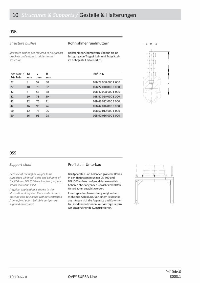
10 Structures & Supports / Gestelle & Halterungen
10.10-Rev. 0 QVF® SUPRA-LineP410de.0
8003.1
Rohrrahmenrundmu� ern
Structure bushes are required to � x support brackets and support saddles in the structure.
Rohrrahmenrundmu� ern sind für die Be-fes� gung von Tragwinkeln und Tragsä� eln im Rohrgestell erforderlich.
Structure bushes
For tube /Für Rohr
Mmm
Lmm
Hmm
Ref.-No.
2727 88 5757 5050 0SB 27 008 000 E 0000SB 27 008 000 E 000
2727 1010 7878 5252 0SB 27 010 000 E 0000SB 27 010 000 E 000
4242 88 5757 6868 0SB 42 008 000 E 0000SB 42 008 000 E 000
4242 1010 7878 6969 0SB 42 010 000 E 0000SB 42 010 000 E 000
4242 1212 7575 7171 0SB 42 012 000 E 0000SB 42 012 000 E 000
4242 1616 9595 7474 0SB 42 016 000 E 0000SB 42 016 000 E 000
6060 1212 7575 9595 0SB 60 012 000 E 0000SB 60 012 000 E 000
6060 1616 9595 9898 0SB 60 016 000 E 0000SB 60 016 000 E 000
0SB
Because of the higher weight to be supported when tall units and columns of DN 800 and DN 1000 are involved, support stools should be used.A typical applica� on is shown in the illustra� on alongside. Plant and columns must be able to expand without restric� on from a � xed point. Suitable designs are Suitable designs are supplied on request.supplied on request.
Bei Apparaten und Kolonnen größerer Höhen in den Hauptabmessungen DN 800 und DN 1000 müssen aufgrund des wesentlich höheren abzufangenden Gewichts Pro� lstahl-Unterbauten gewählt werden.
Eine typische Anwendung zeigt neben-stehende Abbildung. Von einem Festpunkt aus müssen sich die Apparate und Kolonnen frei ausdehnen können. Auf Anfrage liefern Auf Anfrage liefern wir entsprechende Kunstruktionen.wir entsprechende Kunstruktionen.
0SS
Support stool Pro� lstahl-Unterbau

10 Structures & Supports / Gestelle & Halterungen
10.11-Rev. 0QVF® SUPRA-LineP410de.08003.1
Sie dienen im Nennweitenbereich DN 80 bis DN 600 als Grundelement für einen Fest-punkt und werden über Rohre und Verbinder waagerecht im Gestell mon� ert. Gefäße der Nennweite DN 800 und DN 1000 werden auf Rohrrahmenrundmu� ern gesetzt. Die Be-fes� gung von zylindrischen Bauteilen erfolgt dann direkt über eine Festpunktverbindung. Das Befes� gungsmaterial für den Rohrrahmen und die benö� gten Stehbolzen gehören zum Lieferumfang.
These frames are used in the range of nominal sizes DN 80 to DN 600 as a base element for a � xed point and are installed horizontally. Cylindrical vessels of DN 800 and DN 1000 are placed on structure bushes. Cylindrical components are � xed directly via a � xed point connec� on. The material required to � x the support frames and the screwed rod required are in the scope of supply.
Tube frame Rohrrahmen
DN L L1 L2 L3 K nxd Ref.-No.
8080 9292 5151 195195 150150 133133 3xM83xM8 0TF 27 008 000 S 0000TF 27 008 000 S 000
100100 107107 6363 235235 200200 178178 3xM83xM8 0TF 27 010 000 S 000 0TF 27 010 000 S 000
150150 145145 8383 300300 200200 254254 3xM83xM8 0TF 27 015 000 S 000 0TF 27 015 000 S 000
150150 147147 8888 300300 200200 254254 3xM83xM8 0TF 42 015 000 S 0000TF 42 015 000 S 000
200200 168168 120120 305305 200200 280-295280-295 3xM83xM8 0TF 42 020 000 S 0000TF 42 020 000 S 000
300300 218218 119119 436436 210210 395-400395-400 3xM83xM8 0TF 42 030 000 S 0000TF 42 030 000 S 000
450450 313313 133133 640640 280280 585585 3xM123xM12 0TF 42 045 000 S 0000TF 42 045 000 S 000
600600 379379 226226 700700 330330 710710 3xM123xM12 0TF 42 060 000 S 0000TF 42 060 000 S 000
0TF
Technical data Technische Daten
Tube frame / Rohrrahmen
DN Load / Tragkra Fmax N
Tube Ø /Rohr Ø mm
0TF 27 008 000 S 0000TF 27 008 000 S 000 8080 45004500 2727
0TF 27 010 000 S 000 0TF 27 010 000 S 000 100100 53005300 2727
0TF 27 015 000 S 000 0TF 27 015 000 S 000 150150 88008800 2727
0TF 42 015 000 S 0000TF 42 015 000 S 000 150150 1280012800 4242
0TF 42 020 000 S 0000TF 42 020 000 S 000 200200 1300013000 4242
0TF 42 030 000 S 0000TF 42 030 000 S 000 300300 1300013000 4242
0TF 42 045 000 S 0000TF 42 045 000 S 000 450450 1450014500 4242
0TF 42 060 000 S 0000TF 42 060 000 S 000 600600 1330013300 4242
Blue coated, op� on key: „B“ Blau lackiert, Variantenschlüssel: „B“

10 Structures & Supports / Gestelle & Halterungen
10.12-Rev. 0 QVF® SUPRA-LineP410de.0
8003.1
Vl
H L K d1 Type Ref.-No.
55 -- 7878 254254 3x113x11 AA 0VR 00 005 000 E 0000VR 00 005 000 E 000
1010 -- 106106 254254 3x113x11 AA 0VR 00 010 000 E 0000VR 00 010 000 E 000
2020 -- 138138 254254 3x113x11 AA 0VR 00 020 000 E 0000VR 00 020 000 E 000
5050 126126 270270 395395 3xM123xM12 BB 0VR 00 050 000 B 0000VR 00 050 000 B 000
100100 122122 330330 400400 3xM123xM12 BB 0VR 00 100 000 B 0000VR 00 100 000 B 000
200200 118118 360360 585585 3xM123xM12 BB 0VR 00 200 000 B 0000VR 00 200 000 B 000
500500 267267 505505 800800 4x184x18 BB 0VR 00 500 000 B 0000VR 00 500 000 B 000
DN H L K d1 Type Ref.-No.
450 126 270 395 3 x M12 B 0VR 00 050 000 B 000
600 122 330 400 3 x M12 B 0VR 00 100 000 B 000
0VR
These vessel holders are used to support spherical and reduced cylindrical receiver vessels. Standard vessels are � xed at the neck. The metal casing of the holder is cast aluminium or steel epoxy resin painted. The support rings are made from stainless steel.
Vessel holder Tragschale
Die Montage von Kugeln und zugezogenen Vorlage-Zylindergefäßen erfolgt in Tragschalen und Tragringen. Standard-Zylindergefäße werden am Hals aufgehängt. Der metallische Teil besteht aus Aluminiumguss oder Stahl und ist mit Epoxidharzlack geschützt. Die Tragringe bestehen aus Edelstahl.
For spherical vessel für Kugelgefäß
For cylindrical vessel, receiver* für Zylindergefäß, zugezogen*
* all other cylindrical vessels are hold at the neck. * alle anderen Zylindergefäße werden am Hals aufgehängt

10 Structures & Supports / Gestelle & Halterungen
10.13-Rev. 0QVF® SUPRA-LineP410de.08003.1
These brackets are used to support horizontal assemblies in the nominal size range of DN150 to DN300. They are � � ed to a coupling using longer screws and � xed by means of structure bushes. Angled support brackets are supplied in stainless steel as standard.
Für den horizontalen Einbau von Apparaten der Nennweiten DN 100 bis DN 300 in Rohrgestelle eignen sich diese Tragwinkel. Sie werden unter Verwendung längerer Schrauben an eine Flanschverbindung ange-schraubt und über Rohrrahmenrundmu� ern an Querrohren befes� gt. Tragwinkel werden standardmäßig in Edelstahlausführung geliefert.
To suit / Passend fürDN
K H L L1 L2 d Ref.-No.
100 178 8 165 110 30 13 0AB 10 000 000 E 000
150-300 225 9 208 200 40 14 0AB 15 000 000 E 000
0AB
Angled support bracket, stainless steel Tragwinkel, Edelstahl
Für den horizontalen Einbau von Apparaten der Nennweiten DN 450 bis DN 800 eignen sich diese Tragsä� el mit Spannband. Das Unterteil besteht aus einem gebogenen Flacheisen mit segmen� erter Gummi-Aus-kleidung und einer Stützkonstruk� on aus Pro� lstahl. Es wird über Rohrrahmenrund-mu� ern (0SB...) und Gestellrohrverbinder an Querrohren befes� gt. Die Tragsä� el werden in verzinkter Ausführung geliefert.
These support saddles with bracing strap are designed to support DN 450 up to DN 800 assemblies. The lower part consists of a steel bar with segmented rubber lining and a pro� led steel support frame. It is � xed by means of structure bushes (0SB...) and structure � � ngs to the horizontal structure tubes. Support saddles are supplied with a galvanised � nish.
Support saddle Tragsa� el
0SS
To suit / Passend fürDN
L L1 L2 d Ref.-No.
450450 280280 300300 4040 1818 0SS 45 000 000 S 0000SS 45 000 000 S 000
600600 362362 400400 5050 1818 0SS 60 000 000 S 0000SS 60 000 000 S 000
800800 475475 630630 5050 1818 0SS 80 000 000 S 0000SS 80 000 000 S 000
Blue coated, op� on key: „B“ Blau lackiert, Variantenschlüssel: „B“

10 Structures & Supports / Gestelle & Halterungen
10.14-Rev. 0 QVF® SUPRA-LineP410de.0
8003.1
Galvanised pipe brackets are supplied as standard. They can be connected directly to a coupling. Longer srewas are in the scope of supply. Up to DN 50 the pipe bracket can be used as a � xed point with a load of 50 kg. In this case the can� lever has to be supported by a slant tube. Above DN 50 the pipe bracket is used as a guidance.
Halteklauen werden standardmäßig in verzinkter Ausführung geliefert. Sie können unmi� elbar an einer Flanschverbindung befes� gt werden. Die erforderlichen ver-längerten Bolzen sind im Lieferumfang ent-halten. Bis zur Nennweite DN 50 kann die Halteklaue als Festpunkt mit einer Tragkra� von 50 kg verwendet werden. Dafür ist der Kragarm mit einer Diagonalen abzustützen.
Bei größeren Nennweiten dient die Halte-klaue als Führung.
To suit /Passend fürDN
L L1 L2 K D d1 d2 Type Ref.-No.
25 65 27 7,0 70 87 27 9 A 0PB 02 027 000 N 000
40 65 27 7,0 86 103 27 9 A 0PB 04 027 000 N 000
50 70 27 7,0 98 115 27 9 A 0PB 05 027 000 N 000
80 100 30 16 133 156 27 9 A 0PB 08 027 000 N 000
80 80 31 30 133 160 42 12,5 B 0PB 08 042 000 N 000
100 103 31 30 178 205 42 12,5 B 0PB 10 042 000 N 000
150 140 31 40 254 281 42 12,5 B 0PB 15 042 000 N 000
200 164 31 50 295 328 42 11 B 0PB 20 042 000 N 000
300 220 31 50 400 440 42 11 B 0PB 30 042 000 N 000
0PB
Pipe bracket Halteklauen
Blue coated, op� on key: „B“ Blau lackiert, Variantenschlüssel: „B“

10 Structures & Supports / Gestelle & Halterungen
10.15-Rev. 0QVF® SUPRA-LineP410de.08003.1
Sie bestehen aus einer zweiteiligen Gummi-pla� e, die das Glasrohr umspannt und über ein gebogenes Rundeisen an eine S� rnpla� e geschraubt wird. Letztere ist mit einem angesetzten Rohrstück zur Aufnahme kurzer Gestellrohre versehen. Rohrhalter werden standardmäßig mit Metallteilen in verzinkter Ausführung geliefert.
Bei sachgemäßem Einbau stellen sie keinen Festpunkt dar.
Pipe support
They consist of a two-piece rubber collar which grips the glass pipe � rmly and a ‘U’ bolt � xed to a backplate. The la� er has a socket so that it can be connected to the structure. Pipeline supports are supplied with metal parts either in galvanised version or stainless steel as standard. When correctly installed they do not cons� tute a � xed point.
Rohrhalter
0PS
To suit /Passend fürDN
L H H1 H2 d Ref.-No.
15 38 73 85 20 28 0PS 01 027 000 N 000
25 38 73 85 20 28 0PS 02 027 000 N 000
40 56 103 110 20 28 0PS 04 027 000 N 000
50 56 103 110 20 28 0PS 05 027 000 N 000
80 81 155 165 20 28 0PS 08 027 000 N 000
100 81 155 165 20 28 0PS 10 027 000 N 000
150 127 255 270 40 28 0PS 15 027 000 N 000
200 154 299 310 40 44 0PS 20 042 000 N 000
300 189 374 390 40 44 0PS 30 042 000 N 000
Backplate blue coated, U bolt stainless steel, op� on key: „B“
Bügelhalter blau lackiert, Rundeisen Edelstahl, Variantenschlüssel: „B“

10 Structures & Supports / Gestelle & Halterungen
10.16-Rev. 0 QVF® SUPRA-LineP410de.0
8003.1
Pipe Hanger consist of two parts, one having a cap� ve nut welded to it the other not. A lock nut is also required. Standard pipe hangers are galvanised.
Rohrschellen sind zweiteilig ausgeführt und an einer Halbschale mit einer angeschweißten Mu� er versehen. Eine Kontermu� er ist er-forderlich. Rohrschellen werden standard-mäßig in verzinkter Ausführung geliefert.
Pipe hanger Rohrschelle
0PH
To suit /Passend fürDN
d Ref.-No.
15 M10 0PH 01 010 000 S 000
25 M10 0PH 02 010 000 S 000
40 M12 0PH 04 012 000 S 000
50 M12 0PH 05 012 000 S 000
80 M12 0PH 08 012 000 S 000
100 M12 0PH 10 012 000 S 000
150 M12 0PH 15 012 000 S 000
200 M12 0PH 20 012 000 S 000
300300 M12M12 0PH 30 012 000 S 0000PH 30 012 000 S 000
Stainless steel, op� on key: „E“ Edelstahl, Variantenschlüssel: „E“

10 Structures & Supports / Gestelle & Halterungen
10.17-Rev. 0QVF® SUPRA-LineP410de.08003.1
0PC
Fi� ng support structures with safety screens meets two safety requirements at the same � me: opera� ng personnel are protected from hazards that may arise from possible malfunc� ons and the units are protected against mechanical damage arising from external sources. Safety screens consist of sheets of medium � exibility transparent PVC. Hooks are � � ed to the top edge to enable the safety screen to be suspended from the structure. The maximum possible length H is 6 metres.The required height should be added to the catalogue reference.We can also supply rigid PVC safety screens with an� sta� c coa� ng.
Durch das Abhängen von Rohrgestellen mit Schutzwänden werden zwei der Sicher-heit dienende Vorkehrungen gleichzei� g getro� en. Das Bedienungspersonal wird vor den Gefahren geschützt, die von eventuellen Betriebsstörungen ausgehen, und die Anlagen vor Beschädigungen durch mechanische Einwirkungen von außen. Schutzwände bestehen aus einer weich eingestellten, transparenten PVC-Bahn. Am oberen Ende sind Haken angebracht, die das Anhängen der Schutzwand an ein Rohr-gestell ermöglichen. Die maximal mögliche Länge H beträgt 6 m.
Bei Au� ragserteilung ist die Bestell-Nr. um die gewünschte Höhe zu ergänzen.
Auf Anfrage liefern wir Schutzwände aus PVC-hart mit an� sta� scher Beschichtung.
Protec� ve cover Schutzwand
L L1 Type H H1 Tube / Rohr Ø Ref.-No.
400 - A variabel 55 27 0PC 27 040 ??? N 000
500 - A variabel 55 27 0PC 27 050 ??? N 000
600 - A variabel 75 42 0PC 42 060 ??? N 000
700 - A variabel 75 42 0PC 42 070 ??? N 000
800800 -- AA variabelvariabel 7575 4242 0PC 42 080 ??? N 0000PC 42 080 ??? N 000
900900 -- AA variabelvariabel 7575 4242 0PC 42 090 ??? N 0000PC 42 090 ??? N 000
10001000 -- AA variabelvariabel 7575 4242 0PC 42 010 ??? N 0000PC 42 010 ??? N 000
11001100 -- AA variabelvariabel 7575 4242 0PC 42 011 ??? N 0000PC 42 011 ??? N 000
11001100 -- AA variabel variabel 105105 6060 0PC 60 011 ??? N 0000PC 60 011 ??? N 000
14001400 720720 BB variabelvariabel 105105 6060 0PC 60 014 ??? N 0000PC 60 014 ??? N 000
15101510 775775 BB variabelvariabel 105105 6060 0PC 60 151 ??? N 0000PC 60 151 ??? N 000
16001600 820820 BB variabelvariabel 105105 6060 0PC 60 160 ??? N 0000PC 60 160 ??? N 000
16801680 860860 BB variabelvariabel 105105 6060 0PC 60 168 ??? N 0000PC 60 168 ??? N 000
19301930 985985 BB variabelvariabel 105105 6060 0PC 60 193 ??? N 0000PC 60 193 ??? N 000
Design key 2 Design key 2 Length of protective coverLength of protective coverExample:Example:
Ausführungsschlüssel 2 Ausführungsschlüssel 2 Länge der SchutzwandLänge der SchutzwandBeispiel:Beispiel:
Length of protec� ve Cover / Schutzwandlänge H = 2 850 mm 285