![[Aviation] Aircraft Quickie Construction Plans](https://static.fdocuments.in/doc/165x107/551867444a7959df108b4643/aviation-aircraft-quickie-construction-plans.jpg)
Quickie® Rehab Control - Scootaround
19
Owner’s Manual Quickie ® Rehab Control Powered by Delphi ® QR Quickie ® Rehab Control Improving People’s Lives
Transcript of Quickie® Rehab Control - Scootaround

O w n e r ’ s M a n u a l
Quickie® Rehab Control
Powered by Delphi®
QR
Q u i c k i e ® R e h a b C o n t r o l
Improving People’s Lives

014806 Rev. A 2
CONTENTS
TABLE OF CONTENTS
1. REHAB CONTROL MODELS OVERVIEW............................................. 3A. Quickie Rehab Motor Control .................................................................... 3
B. Driver Input Types....................................................................................... 3
C. Displays to Driver........................................................................................ 3
D. Non-Driving Interface Modules................................................................... 4
E. Customizing the System.............................................................................. 4
II. WARNINGS AND CAUTIONS .............................................................. 4A. EMI (Electromagnetic Interference) ............................................................ 4
B. What is EMI? ................................................................................................ 4
C. What Effect Can EMI Have? ........................................................................ 4
D. Sources of EMI ............................................................................................ 5
E. Distance From EMI Sources........................................................................ 5
F. EMI Immunity Level..................................................................................... 5
G. Report All Suspected EMI Incidents ............................................................ 5
H. Controller Settings ...................................................................................... 5
I. Safety Check-List......................................................................................... 5
J. Changes and Adjustments ........................................................................... 5
K. When Seated in a Parked Wheelchair ......................................................... 5
L. Environmental Conditions ........................................................................... 6
III. SYSTEM TIMEOUT OR LONG MODE TO TURN OFF POWER.......... 6IV. OPERATION USING HANDCONTROLS.............................................. 6
A. Keyless Lock Function ................................................................................. 6
B. Auto Mode Enabled or Standby Function .................................................. 6
C. Operation of Wheelchair Using QR-3: 3 Button Handcontrol ................... 7
D. Operation of Wheelchair using QR-7 (Europe only): Compact Joystick .... 8
E. Operation of Wheelchair Using QR-2: Compact Joystick........................... 9
V. QUICKIE ENHANCED DISPLAY ........................................................... 10VI. OPERATION OF WHEELCHAIR USING SPECIALTY
CONTROL MODULE (QR-SCM)............................................................ 10A. Quickie Enhanced Display ........................................................................... 10
B. Specialty Input Control................................................................................ 10
C. Power On/Off and Mode Ports................................................................... 10
D. Input Devices............................................................................................... 11
VII. OPERATION OF SEATING FUNCTIONS ............................................. 12A. Operation of Seating Functions Using Handcontrols .................................. 12
B. Operation of Seating Functions Using Direct Actuator Switch................... 12
C. Operation of Seating Actuators with Hex Switch and QMAC.................... 13
D. Drive Creep Mode and Drive Lockout ....................................................... 13
E. Function with a Lift Module Present ........................................................... 14
VIII. OPERATION OF ECM FUNCTIONS ..................................................... 14IX. TROUBLESHOOTING............................................................................ 14
A. Display Devices. .......................................................................................... 14
B. Display Methods.......................................................................................... 14
C. Coded Display ............................................................................................. 14
D. Textual Display............................................................................................. 14
E. Diagnostic Messages with Coded Displays ................................................. 14
F. Drive Mode Faults ....................................................................................... 14
G. Power Seating Mode ................................................................................... 16
H. Diagnostic Messages with Text Displays...................................................... 18

014806 Rev. A3
I
I . REHAB CONTROL MODELS OVERVIEW
I. REHAB CONTROL MODELS OVERVIEW
The Quickie electronic control system made by Delphi® repre-sents a new means with which to operate powered wheelchairs.Sunrise Medical has been manufacturing powered mobility devicesfor many years and has acquired a vast knowledge of the clinicalneeds of those using powered wheelchairs. Delphi is one of thelargest manufacturers of electronics with a worldwide presenceand brings exceptional engineering design and manufacturingknowledge to powered wheelchair controls. The combination ofthese two companies has produced a breakthrough in electroniccontrols that exceeds the reliability and durability standards tradi-tionally seen in the powered wheelchair industry.
For rehabilitation applications, the family of Quickie electronicmodules made by Delphi begins with the Quickie Rehab (QR) plat-form. This series of controls are designed with the unique needs ofthe individual in mind. These controls are highly customizable andoffer an unmatched level of expansion as needs change over time.Significant research and development has gone into providing theQuickie Rehab controls to provide a system that is intuitive whileoffering features new to the power wheelchair industry.
The electronic control system of a power wheelchair is made ofseveral modules that work together to provide driving as well asoptional functions such as powered seating, lights, and environmen-tal controls. An overview of this system is shown below:
A. QUICKIE REHAB MOTOR CONTROLMODULE:
This module is similar to the main processing unit of a personalcomputer. The QR Motor Control Module takes the input fromyou and delivers information and commands to the motors for driv-ing, actuators for powered seating and even to external devices likea mouse emulator for a computer, environmental control unit or acommunication device.
• Controls the speed and direction of the wheelchair via twoindependent direct current (DC) motors and electro-mechanical brakes
• Estimates the battery charge level and acts as a “gateway”for battery charging (i.e. the battery and charger each con-nect directly to the motor control module)
• Can interface and control optional actuator modules forpower assisted seat functions
• Can interface and control optional external technologies suchas a mouse emulator for a computer, environmental controlunit or a communication device.
• Acts as the system “hub” for any centralized wheelchair func-tions
B. DRIVER INPUT TYPES:The Quickie QR platform can receive direction or input from avariety of module types. These inputs are dictated by the uniqueneeds of the operator. They range from hand function to switchinputs such as sip n’ puff or head control. This platform is designedto optimize the function of the operator and ensure safe, simpleand effective driving.
1. QR-3 Rehab Joystick or Handcontrol (3 buttons) • Identified by 3 buttons• Provides a joystick for those that desire this modality of input • Provides discrete switches for operator input to control
power on/off, function selector (via permanent keypadswitches and/or via optional phono jacks)
• Provides optional rotary speed dial to let you adjust yourspeed
• Provides discrete LED displays for feedback to the driverthrough the QR-3
• Provides acoustic output for feedback to the driver andwarning horn
• Can interface with a wide variety of knob choices such as agoal post and ball.
2. QR-SCM: Specialty Control Module (SCM)• Converts an switch type input into commands that the QR
Motor Control Module can interpret • Provides an interface for special input devices such as Sip-
and-Puff, ASL, Switch-It, Tash discrete switches, HeadControl, and others
• Provides a lighted display, through the Quickie EnhancedDisplay, for feedback to operator as to power status andmode of operation
3. QR-2: Compact Joystick (2 buttons)/ Q-AD Attendant Control• Identified by 2 buttons• Can be used for chin driving or when a small operator joy-
stick is desired • Can be used to provide joystick operation for an attendant
override to the primary driver• Comes standard with discrete switches for power on/off and
mode select• Provides a lighted display for feedback to operator • Provides acoustic output for feedback to operator and warn-
ing horn
C. DISPLAYS TO DRIVER:When a QR-2 joystick module or a QR-SCM is used, the Quickieenhanced lighted display (QR-ED) acts as the “dashboard” for theoperator. These lights indicate power level, mode, drive profilenumber and many additional features.
Enhanced Display Module: QR-ED• Provides the operator with a clear, easy to see display that
can illustrate text and icons. • Can provide acoustic output for feedback to driver and
warning horn
Quickie QRMotor Control
ModuleYour joystick
Poweredwheelchair
motors
Powered Seating Systems
Specialty ControlModule – QR-
SCM
Lights,Communication
Device,Computer, etc.
Your Specialdrivingsystem

014806 Rev. A 4
1
• Ideal for interfacing with external systems such as a mouseemulator, communication device or a radio frequency con-trolled ECU system.
• Can have up to two modules which provide four channels.
E. CUSTOMIZING THE SYSTEM:Like your computer system, the Quickie QR platform has a wealthof software programming options to ensure that the input and per-formance is intimately matched to the wants and needs of theoperator. Below you will see the options for programming or cus-tomizing the platform:
HandHeld Programmer• Service tool for the modification of calibration parameters,
and monitoring of system values
PC Simulation Program (software only – Available Fall 2006)• Personal Computer based software for demonstrating the
operational features of the wheelchair system
PC Setup Station (software only – Available Fall 2006)• Dealer/clinician tool used to customize and troubleshoot the
QR system. Your Quickie QR wheelchair controls may be configured with awide variety of hardware and software options for your individualneeds. Your dealer, clinician or other rehabilitation technical special-ist normally does this set up.
Refer to the appropriate sections of this Owner’s Manual for opera-tion of each of these options based on your specific controls configu-ration. If you are unsure of your specific controls configuration,please consult your dealer, clinician or call Sunrise Customer Service.
• When interfacing with infra-red capable devices in your envi-ronment, the enhanced display provides integrated Infra-Redlearning for remote control functions
D. NON-DRIVING INTERFACE MODULES:The Quickie QR platform provides seamless interfacing with a vari-ety of non-driving functions. These functions such as poweredseating operation and alternative switch devices (i.e. mouse emula-tor, environmental controls, communication devices, etc.) can befully controlled right from your input module. This turnkey systemwill allow you to select a driving mode, a powered seating mode oran ECU mode to tell the system what you desire to do. The fol-lowing modules describe interfacing with non-driving systems:
Quickie Multi Actuator Control (QR-MAC) Module - optional• This module is used to control multiple seating functions.
For those times when a single or double powered seatingsystem is required, then the operation will not require thismodule as the function is already built into your operatorinput. Instead the QR-MAC is needed for multiple actuatorsystems up to 7 actuators.
• Through the QR-MAC, the operator commands the pow-ered seating system fully, with independent control of tilt,recline, shear reduction, elevating seat and powered elevat-ing legrests.
• Additionally the QR-MAC can allow customizable settings toyour powered seating system (i.e. the range of tilt or recline,when functions will operate together – recline and poweredlegs versus independently.
Environmental Control Module (QR-ECM)• Designed to control nine general purpose relay outputs• Provides a selectable voltage power supply output
I I . WARNINGS AND CAUTIONS
2. There are a number of sources of intense EMI in your dailyenvironment. Some of these are obvious and easy to avoid.Others are not, and you may not be able to avoid them.
3. Powered wheelchairs may be susceptible to electromagneticinterference (EMI) emitted from sources such as radio sta-tions, TV stations, amateur radio (HAM) transmitters, two-way radios, and cellular phones.
4. EMI can also be produced by conducted sources or electro-static discharge (ESD).
C. WHAT EFFECT CAN EMI HAVE?WARNING
1. EMI can cause your chair, without warning, to:• Release its brakes• Move by itself• Move in unintended directionsIf any of these occurs, it could result in severe injury to youor others.
2. EMI can damage the control system of your chair. This couldcreate a safety hazard, and lead to costly repairs.
II. WARNINGS AND CAUTIONS
A. EMI (ELECTROMAGNETIC INTERFERENCE)
WARNINGHeed all warnings to reduce the risk of unintendedbrake release or chair movement:
1. Beware of the danger from hand-held transceivers. Neverturn on or use a hand-held transceiver while power to yourchair is on. Use extra care if you believe that such a devicemay be in use near your chair.
2. Be aware of nearby radio or TV stations, and avoid comingclose to them.
3. If unintended movement occurs or unintended brake releaseoccurs, turn your chair off as soon as it is safe to do so.
B. WHAT IS EMI?WARNING
1. EMI means: electromagnetic (EM) interference (I). EMIcomes from radio wave sources such as radio transmittersand transceivers. (A “transceiver” is a device that both sendsand receives radio wave signals).

014806 Rev. A5
II
D. SOURCES OF EMIWARNING
The sources of EMI fall into three broad types:
1. Hand-Held Transceivers: The antenna is usually mounteddirectly on the unit. These include: Citizens band (CB)radios, “Walkie-talkies”, Security, fire and police radios,Cellular phones, Lap-top computers with phone or fax,Other personal communication devices
NOTE– These devices can transmit signals while they are on, even if not inuse.
2. Medium-Range Mobile Transceivers: These include two-way radios used in police cars, fire trucks, ambulances andtaxi cabs. The antenna is usually mounted on the outside ofthe vehicle.
3. Long-Range Transceivers: These include commercial radioand TV broadcast antenna towers and amateur (HAM) radios.
NOTE– The following are not likely to cause EMI problems: Lap-top com-puters (without phone or fax), Cordless phones, TV sets or AM/FMradios, CD or tape players.
E. DISTANCE FROM EMI SOURCESWARNING
EM energy rapidly becomes more intense as you get closer to thesource. For this reason, EMI from hand-held devices is of specialconcern. A person using one of these devices can bring high levelsof EM energy very close to your chair without you knowing it.
F. EMI IMMUNITY LEVELWARNING
1. The level of EM energy is measured in volts per meter (V/m).Every power wheelchair can resist EMI up to a certain level.This is called its “immunity level”.
2. The higher the immunity level, the less the risk of EMI. It isbelieved that a 20 V/m immunity level will protect the powerwheelchair user from the more common sources of radiowaves.
3. The configuration tested and found to be immune to at least20 V/m.
Individuals with physical limitations requiring the use of a specialtycontrol input device known not to be immune to 20 V/m, or notknown, should exercise extra care around known sources of EMI.
There is no way to know the effect on EMI if you add accessoriesor modify this chair. Any change to your chair may increase the riskof EMI. Parts from other suppliers have unknown EMI properties.
G. REPORT ALL SUSPECTED EMI INCIDENTS
WARNINGYou should promptly report any unintended movement or brakerelease. Be sure to indicate whether there was a radio wave sourcenear your chair at the time.
Contact Sunrise Medical Customer Service Department at (800) 333-4000.
H. CONTROLLER SETTINGSWARNING
Program settings beyond the ability of the rider canresult in serious injury. Consult your health care advi-sor before you alter settings.
1. Never use the ON/OFF switch to stop your chair except inan emergency. This will result in an abrupt stop, and maycause you to fall.
2. To slow or stop your chair, return the joystick to neutral Be aware that your dealer may need to adjust the controller set-tings of your chair to reduce the risk of a collision, fall or tip-over.
1. Check and adjust the settings every six to twelve months (ormore often, if needed).
2. Consult your supplier to adjust the control settings immedi-ately if you notice any change in your ability to: • Control the joystick.• Hold your torso erect.• Avoid running into objects.
I. SAFETY CHECK-LISTWARNING
Before each use of this chair:1. Make sure the chair operates smoothly. Check for noise,
vibration, or a change in ease of use. (They may indicate lowtire pressure, loose fasteners, or damage to your chair).• If you detect a problem, make sure to repair or adjust
the chair. Deferring repair or adjustment could increasethe risk for injury. Your supplier can help you find andcorrect the problem.
2. Make sure batteries are charged. Green lights on charge indi-cator will light up when charge is full. Yellow lights indicatebattery charge level is getting low. Red lights indicate batter-ies are in immediate need of charging.
J. CHANGES & ADJUSTMENTSWARNING
Never use non-Quickie parts or make changes toyour chair unless authorized by Sunrise. (Doing somay create a safety hazard).
1. If you modify or adjust this chair it may increase the risk of afall or tip-over.
2. Modifications unauthorized by Sunrise constitutes remanufac-turing of the wheelchair. This voids the warranty. The riderthen assumes all future liability for the wheelchair.
K. WHEN SEATED IN A PARKED WHEELCHAIR
WARNING1. Always turn off your chair when you are parked, even for a
moment. This will prevent:• Accidental movement from contact with the joystick by
you or others.• Unintended brake release or movement from EMI
sources. (See Section II-D)2. Make sure that persons who help you (for example: store
clerks) are aware of the joystick and do not touch it. If theydo, your chair may move suddenly when you do not expect it.

014806 Rev. A 6
II , I I I , IV
• Make sure battery cover is secure.• Replace joystick boot if it becomes torn or cracked.• Make sure all electrical connections are secure.• Dry the chair as soon as you can if it gets wet, or if you
use water to clean it.2. Proceed slowly and use extra care if you must operate your
chair on a wet or slick surface.• Do so only if you are sure it is safe.• Stop if one or both main wheels lose traction. If this
occurs, you may lose control of your chair or fall.• Never operate your chair on a slope or ramp if there is
snow, ice, water or oil film present.• When in doubt, have someone help you.
3. When not in use, keep your chair in a clean, dry place.
L. ENVIRONMENTAL CONDITIONSWARNING
Your chair is not designed for use in a heavy rainstorm, or in snowy or icy conditions.
1. Contact with water or excessive moisture can cause an elec-trical malfunction. The frame, motors and other chair partsare not water-tight and may rust or corrode from the inside.To avoid a chair failure:• Minimize exposure of your chair to a rain storm or very
wet conditions.• Never take your chair into a shower, tub, pool or sauna.• Do not use your chair in fresh or salt water (such as at
the edge of a stream, lake, or ocean).• Do not use a garden hose or pressure washer to clean
your chair
I I I . SYSTEM TIMEOUT OR LONG MODE TO TURN OFF POWER
set from 0 minutes to 720 minutes. There are two timers. A power-save timer that shuts down the system to conserve power and canbe awakened by a long command (intended for Sip & Puff users)and a system timeout that shuts down the system completely.
A long mode command or holding the mode button for more than5 seconds will put the controls into power save mode or suspend.
III. SYSTEM TIMEOUT OR LONG MODE
In addition to the on/off buttons, there are two other ways to turnoff the control’s power.
If this feature is enabled, your wheelchair controls will automaticallypower off when unused for a long period of time to conserve bat-tery power. This time is programmable by your dealer, and can be
IV. OPERATION USING HANDCONTROLS
B. AUTO MODE ENABLED OR STAND-BY FUNCTION
The Quickie Rehab platform comes with the ability to use time tosend the power wheelchair into a waiting mode that allows you tooperate functions other than driving. Programmable by yourprovider, this auto mode or stand-by mode occurs when there isno movement of the joystick or driver input for the programmedtime. This option is available in one or multiple drive profiles. Youwill know that you have entered this mode because the small lightnext to the mode button will turn red. During this time, you canchoose to drive again or select one of 3 alternative functions: pro-file select, powered seating mode, or alternative control (ECU)mode. The forward direction will always return you to active driv-ing and the light will return to green. The left and right turns andreverse directions are active depending on what you have on yourchair. A left command goes to drive profile select. Once there,move joystick in direction of profile desired per the drive profilepiechart and the selection is made. Control will return to drivingimmediately. The reverse direction will send you to ECM modeselect (only active if an ecm is on the chair – mode light becomesamber, move joystick in direction of channel desired per the driveprofile select piechart. Once the ECM channel is selected joystickcontrols that port until a mode switch is hit. A right commandgoes into actuator mode.
IV. OPERATION USING HANDCONTROLS
A. KEYLESS LOCK FUNCTIONIf your wheelchair has the keyless lock function enabled, then youcan use your handcontrol to “lock out” the wheelchair control toprevent someone else from tampering with the system, and thenunlock it to drive it yourself again.
To lock your control, perform the following sequence – press andhold the on/off switch for 5 seconds while simultaneously holdingthe joystick all the way forward. To unlock your chair, perform thefollowing sequence press. Hold the on/off switch for 5 secondswhile simultaneously holding the joystick all the way in reverse.
If you ever lock your wheelchair controls and forget the sequenceto unlock, please call your power wheelchair provider.
_____________________________________________(record phone # here)

014806 Rev. A7
IV
Battery State of Charge IndicatorGaugeWhen the green lights are solid and steady, the battery has a highstate of charge. When amber lights are showing, the battery is nothighly charged, but is still charged to some extent. When only thered lights are showing, the battery charge is low, and you should becareful not to run out of battery charge or the wheelchair will nolonger operate. Sunrise Medical recommends charging the wheel-chair as soon as possible when only the red lights are showing. Ifthe lights flash, then this indicates a fault and your power chair sup-plier should be contacted.
Horn buttonWhen depressed, the horn will sound until the button is released.
Mode buttonThe mode button is used to change driving profiles and to changethe control input device where more than one are fitted. The Modebutton is also used for accessing other wheelchair functions, such asseating actuators and control of optional Environmental Controls,based on the functions installed on your chair. A long hold of thisbutton will also cause your chair to go into suspend mode.
1. Using the mode button to select drive profiles• When you press the mode buttononce, the small light near the mode but-ton will become red, and now the joy-stick is used to select the drive profileyou want. Move the joystick all the wayforward to select Drive Profile 1, right toselect Drive Profile 2, in reverse to selectDrive Profile 3 and left to select Drive Profile 4. When youselect a drive profile, the small light for that drive profile willbe red to indicate that it has been selected. After you select adrive profile, the wheelchair automatically goes back intodrive mode and any further movement of the joystick willbegin to move the wheelchair.
2. Using the mode button to select seating functions• If your wheelchair has seating functions installed, youpress the mode button twice to enter seating control mode.The small light by the mode button will be green when youare in seating mode. In seating mode, the green lights on thewheelchair seating icon will indicate which seating actuator iscurrently selected. Moving the joystick left or right willselect different seating actuators. While any of these isselected, moving the joystick forward or reverse will movethe actuator in one direction or the other. Refer to thepower chair manual for more complete directions on seatingactuator control.
3. Using the mode button to select EnvironmentalControls or Alternative Controls Mode• If you press the mode button three times (or twice if yourwheelchair has no seating functions installed), the control willchange into ECM mode and the small light next to the modebutton will be amber. Refer to ECM section later in this man-ual for operation of ECM devices while in ECM mode.• Pressing the mode button cycles the control from driveto drive profile select to seating mode to ECM and then backto drive in sequence. If your wheelchair does not have seat-ing functions or ECM functions installed, then the control sys-tem automatically will skip these modes as the mode buttonis selected in sequence. This will also occur if only one of thefour possible drive profiles is active.
If using auto mode or stand-by mode, refer to Section IV-B.
Once in actuator mode, right cycles through the options,forward/reverse operate the actuator, and a mode switch hit isneeded to drive.
C. OPERATION OF WHEELCHAIR USING 3 BUTTON HANDCONTROL
The wheelchair is operated through the handcontrol module,which should be mounted in a convenient location near your handwhile seated in the wheelchair. The picture below shows the joy-stick and button locations and general purpose for each.
On/Off buttonThis button turns the wheelchair control on and off. You can see ifthe wheelchair control is on by looking at the lights just under theon/off button. If any of the lights are visible, the control is on.
Forward– Active Driving Reverse– ECM Mode Select
Left– Drive Profile Select Right– Actuator Mode
Forward Reverse
Left Right
On/Off
SeatingFunctionIndicatorHorn
Joystick
Drive Profile/ ECMSelect Indicator
ModeButton
BatteryGauge

014806 Rev. A 8
IV
JoystickThe motion of the wheelchair is controlled through the joystick.
1. Operation when Handcontrol programmed for proportional operation:• Press the joystick in the direction you want the chair tomove. The chair will move faster when the joystick is dis-placed more. Returning the joystick to the neutral position,such as by letting go, will cause the chair to stop moving.
2. Operation when Handcontrol programmed for switchoperation:• When programmed for switch operation, the Handcontrolwill operate as a, 4 switch input module. Moving the joystickhalfway in a direction will be the same as activation of aswitch. Refer to the later Switch Input Control section of thisOwners Manual for more complete instructions on operationof the wheelchair using switch inputs.
D. OPERATION OF WHEELCHAIR USING 7BUTTON HANDCONTROL WITHLIGHTS AND INDICATORS (Europe Only)
The wheelchair is operated through the handcontrol module,which should be mounted in a convenient location near your handwhile seated in the wheelchair. The picture below shows the joy-stick and button locations and general purpose for each.
On/Off buttonThis button turns the wheelchair control on and off. You can see ifthe wheelchair control is on by looking at the lights just under theon/off button. If any of the lights are visible, the control is on.
BatteryWhen the green lights are solid and steady, the battery has a highstate of charge. When amber lights are showing, the battery is nothighly charged, but is still charged to some extent. When only thered lights are showing, the battery charge is low, and you should becareful not to run out of battery charge or the wheelchair will nolonger operate. Sunrise Medical recommends charging the wheel-chair as soon as possible when only the red lights are showing. Ifthe lights flash, then this indicates a fault and your power chair sup-plier should be contacted.
Horn buttonWhen depressed, the horn will sound until the button is released.
Mode buttonThe mode button is used to switch from drive mode to selection ofdrive profile, and to operating other wheelchair functions, such asseating actuators and control of optional Environmental Controls,based on the functions installed on your chair. A long commandwill cause your power chair to enter suspend mode.
1. Using the mode button to select drive profiles:• When you press the mode buttononce, the small light near the mode but-ton will become red, and now the joy-stick is used to select the drive profileyou want. Move the joystick all the wayforward to select Drive Profile 1, right toselect Drive Profile 2, in reverse to selectDrive Profile 3 and left to select Drive Profile 4. When youselect a drive profile, the small light for that drive profile willbe red to indicate that it has been selected. After you select adrive profile, the wheelchair automatically goes back intodrive mode and any further movement of the joystick willbegin to move the wheelchair.
2. Using the mode button to select seating functions:• If your wheelchair has seating functions installed, youpress the mode button twice to enter seating control mode.The small light by the mode button will be green when youare in seating mode. In seating mode, the green lights on thewheelchair seating icon will indicate which seating actuator iscurrently selected. Moving the joystick left or right willselect different seating actuators. While any of these isselected, moving the joystick forward or reverse will movethe actuator in one direction or the other. Refer to the laterSeating section of the manual for more complete directionson seating actuator control.
3. Using the mode button to select ECM mode: • If you press the mode button three times (or twice if yourwheelchair has no seating functions installed), the control willchange into ECM mode and the small light next to the modebutton will be amber. Refer to ECM section later in this man-ual for operation of ECM devices while in ECM mode.• Pressing the mode button cycles the control from driveto drive profile select to seating mode to ECM and then backto drive in sequence. If your wheelchair does not have seat-ing functions or ECM functions installed, then the control sys-tem automatically will skip these modes as the mode buttonis selected in sequence.
If using auto mode or stand-by mode, refer to Section IV-B.
JoystickThe motion of the wheelchair is controlled through the joystick.
1. Operation when Handcontrol programmed for proportional operation: • Press the joystick in the direction you want the chair tomove. The chair will move faster when the joystick is dis-placed more. Returning the joystick to the neutral position,such as by letting go, will cause the chair to stop moving.
2. Operation when Handcontrol programmed for switchoperation:• When programmed for switch operation, theHandcontrol will operate as a, 4 switch input module,
On/Off
Assignable
Assignable
SeatingFunctionIndicator Horn
Joystick
Drive ProfileIndicator
ModeButton
BatteryGauge

014806 Rev. A9
IV
Horn FunctionThe horn is accessed through the Driver menu.
Mode buttonThe mode button is used to switch from drive mode to selection ofdrive profile, to seating functions and to control of EnvironmentalControls, depending on the functions installed on your chair.
1. Determining which drive profile is active:• When you first turn on the wheelchair controls, the smalllight by the mode button will be red, and then turn off for1.5seconds followed by a flash once for drive profile 1, twicefor drive profile 2, three times for drive profile 3 or fourtimes for drive profile 4. This is also shown in the upper lefthand corner of the QR-ED screen which displays the numberof drive profile which is active.
2. Using the mode button to select drive profiles: • When you press the mode buttononce, the QR-ED will cycle from theactive drive screen to the Driver Menuscreen. The first item on the DriverMenu is Drive Profile Select. A rightcommand will send you into the DriveProfile Select Screen, at which point aninput command in the direction shown will select that profile.As soon as a selection is made, the screen will return toactive ready to drive.
3. Using the mode button to select seating functions:• If your wheelchair has seating functions installed, youpress the mode button the QR-ED will cycle from the activedrive screen (shown below) to the Driver Menu screen(shown below). On the driver menu will be the poweredseating options available on your chair. A right command willsend you into the powered seating function. A mode com-mand will return you to ready to drive. While any of thesefunctions are selected, moving the joystick forward orreverse will move the actuator in one direction or the other.Refer to the later Seating section of the manual for morecomplete directions on seating actuator control. An audibleacknowledgement is given each time the actuator is changed.
If using auto or stand-by mode, refer to Section IV-B.
JoystickThe motion of the wheelchair is controlled through the joystick.
1. Operation when Handcontrol programmed for proportional operation:• Press the joystick in the direction you want the chair tomove. The chair will move faster when the joystick is dis-placed more. Returning the joystick to the neutral position,such as by letting go, will cause the chair to stop moving.
2. Operation when Handcontrol programmed for switchoperation:• When programmed for switch operation, the Handcontrolwill operate as a 4 switch input module. Moving the joystickhalfway in a direction will be the same as activation of aswitch. Refer to the later Switch Input Control section of thisOwners Manual for more complete instructions on operationof the wheelchair using switch inputs.
depending on how the system was set up. Moving the joy-stick halfway in a direction will be the same as activation of aswitch. Refer to the later Switch Input Control section ofthis Owners Manual for more complete instructions on oper-ation of the wheelchair using switch inputs.
Headlamps buttonPress this button to turn the headlamps on and off. The small lightnext to the button will be lit when the headlamps are on. Youmust press a second time to turn this function off.
Hazard Lights buttonPress this button to turn the hazard lights on and off. The smalllight next to the button will flash when the hazard lights are on.You must press a second time to turn this function off.
Right Turn IndicatorPress this button to turn the turn indicator lights on and off. Thesmall light next to the button will flash when the Right Turn lightsare on. You must press a second time to turn this function off.
Left Turn IndicatorPress this button to turn the turn indicator lights on and off. Thesmall light next to the button will flash when the Left Turn lights areon. You must press a second time to turn this function off.
E. OPERATION OF WHEELCHAIR USINGQR-2 COMPACT JOYSTICK
The wheelchair is operated through the handcontrol module,which should be mounted in a convenient location while seated inthe wheelchair. When used as the primary driver control, the QR-2 should be used with the QR-ED to provide feedback to the user.The picture below shows the joystick and button locations andgeneral purpose for each.
On/Off buttonThis button turns the wheelchair control on and off. You can see ifthe wheelchair control is on by looking at the lights next to theon/off button. If any light is visible, the control is on.
Battery GaugeWhile driving, the small light near the On/Off button will indicatethe battery state of charge. Green indicates high battery charge,amber indicates mid battery charge, red indicates low batterycharge and flashing red indicates very low battery charge. If usedwith a Quickie Enhanced Display, then the battery gauge will beshown on the display screen.
On/Off Modebutton
014806 Rev. A 10
V, VI
V. QUICKIE ENHANCED DISPLAY– USER MENU AND NAVIGATION
V. QUICKIE ENHANCED DISPLAY
The menu visible in the Quickie Enhanced Display is used to navi-gate from one wheelchair function to another. The “Driver Menu”is a customized group of menu selections that was programmed foryou when your wheelchair was set up. The wheelchair functionsthat you use most frequently should be the functions placed in youruser menu at setup.
All the menu items are available in the Operate menu. To get fromthe Driver Menu to the Operate menu, go to the top of the DriverMenu and execute a long left command (more than 3 seconds).
Menu navigation in either the Driver Menu or the Main Menu issimilar to using Windows Explorer on your personal computer.Navigation of the menu is done by using the following commands,which have the following action associated with them:
FORWARD – takes you up the menu.REVERSE – takes you down the menu.LEFT – takes you up one level in the menu.RIGHT – takes you down one level in the menu or activates
the highlighted function.ESCAPE – takes you back to drive mode.
The general menu structure is PROGRAM – Used to enable/disable features and set operat-
ing parameters for various functions
OPERATE – Used to operate wheelchair functions
MONITOR – This section of the menu is used to monitorvarious operating characteristics of the wheel-chair. This is normally used in conjunction withset up and maintenance by a dealer.
INFORMATION – This section of the menu is used to displaymodule information such as model number,serial number, hardware version, software ver-sion, etc. This section of the menu is normallyused by the dealer in maintenance.
FAULTS – This section of the menu is used to display faultfor troubleshooting and maintenance by thedealer.
For more information on the Quickie Enhanced Display, refer tothe Quickie Enhanced Display Manual.
VI. OPERATION OF WHEELCHAIR USING SPECIALTY
CONTROL INPUT MODULE (QR-SCM)
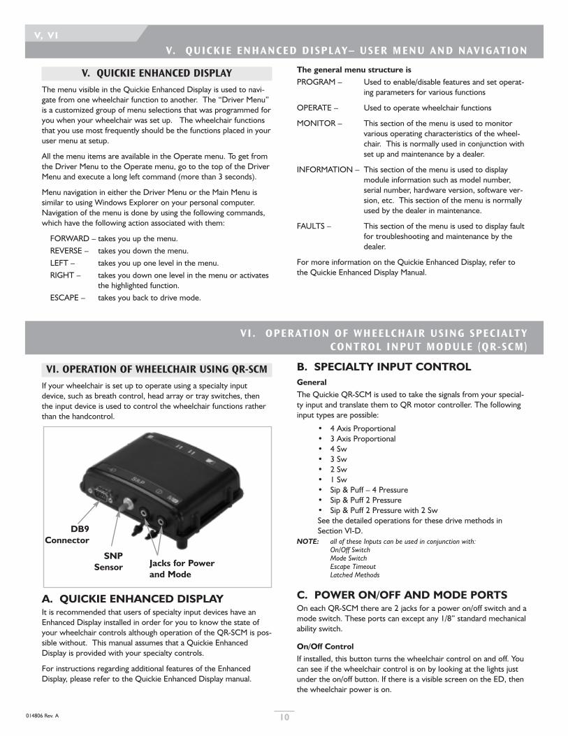
VI. OPERATION OF WHEELCHAIR USING QR-SCM
If your wheelchair is set up to operate using a specialty inputdevice, such as breath control, head array or tray switches, thenthe input device is used to control the wheelchair functions ratherthan the handcontrol.
A. QUICKIE ENHANCED DISPLAYIt is recommended that users of specialty input devices have anEnhanced Display installed in order for you to know the state ofyour wheelchair controls although operation of the QR-SCM is pos-sible without. This manual assumes that a Quickie EnhancedDisplay is provided with your specialty controls.
For instructions regarding additional features of the EnhancedDisplay, please refer to the Quickie Enhanced Display manual.
B. SPECIALTY INPUT CONTROLGeneralThe Quickie QR-SCM is used to take the signals from your special-ty input and translate them to QR motor controller. The followinginput types are possible:
• 4 Axis Proportional• 3 Axis Proportional• 4 Sw• 3 Sw• 2 Sw• 1 Sw• Sip & Puff – 4 Pressure• Sip & Puff 2 Pressure• Sip & Puff 2 Pressure with 2 SwSee the detailed operations for these drive methods inSection VI-D.
NOTE: all of these Inputs can be used in conjunction with:On/Off SwitchMode SwitchEscape TimeoutLatched Methods
C. POWER ON/OFF AND MODE PORTSOn each QR-SCM there are 2 jacks for a power on/off switch and amode switch. These ports can except any 1/8” standard mechanicalability switch.
On/Off ControlIf installed, this button turns the wheelchair control on and off. Youcan see if the wheelchair control is on by looking at the lights justunder the on/off button. If there is a visible screen on the ED, thenthe wheelchair power is on.
DB9 Connector
SNP Sensor Jacks for Power
and Mode

014806 Rev. A11
VI
transitions may be performed by allowing the controlto timeout or use the stand-by mode to progress to thenext mode if your control is so programmed.
b. 3 AxisA 3-axis proportional input device may be configuredwith a separate on/off button and/or may be configuredwith a separate mode button, or the mode transitionsmay be performed by allowing the control to timeout tothe next mode if your control is so programmed. The motion of the wheelchair is controlled throughthe 3-axis input. To toggle between forward andreverse directions, execute a short forward command.If your controls have “FWD/REV MODE” enabledthen the chair will automatically toggle between for-ward and reverse direction on a pre-set programma-ble time cycle.
2. SwitchedSwitched input devices include breath control, switched headarrays, tray switches etc. Inputs to the wheelchair control usingswitches is different depended on the number of switches installedand set up on your wheelchair. Configurations of switches include4 switch, 3 switch, 2 switch, 1 switch, and sip & puff control. Sinceoperation of the wheelchair only depends on the number ofswitches installed and set up, not of the input device itself, eachswitch configuration is described separately below.
a. 4 SwA 4-Switch input device may be configured with a sep-arate on/off button and/or may be configured with aseparate mode button, or the escape timeout may beused if enabled. Alternatively, you may use two shortforward commands in sequence to escape.The motion of the wheelchair is controlled throughthe 4-switch discrete input device. If you press two adjacent directions simultaneously, thewheelchair will move diagonally in those two direc-tions. While driving forward or reverse, if you simulta-neously give the right or left command for a period,the chair will continue moving forward or reverse, butwill turn left or right as long as the adjacent directioncommand is given in order to steer.
b. 3 SwThe motion of the wheelchair is controlled throughthe 3-switch discrete input device. If you execute two adjacent direction commandssimultaneously, the wheelchair will move diagonally inthose two directions. While driving forward or reverse,if you simultaneously give the right or left command fora period, the chair will continue moving forward orreverse, but will turn left or right as long as the adjacentdirection command is given in order to steer.Toggle between forward and reverse direction by exe-cuting a short forward command or, if enabled, allowingthe wheelchair to timeout to toggle direction.
c. 2 SwThe motion of the wheelchair is controlled throughthe 2-switch discrete input device. A forward command is a short left switch closure, fol-lowed by another left switch closure. A reverse com-mand is a short right switch closure, followed byanother right switch closure. In unlatched mode, the
Escape Methods– Means to change from driving to non-driving functions.1. Mode Switch
If installed, the mode button is used to toggle between DriveMode and the Menu Mode.
2. Escape TimeoutIf escape timeout is enabled on your wheelchair, then if youdo not issue any commands, the controls will automaticallyescape after a pre-set length of time. Escape timeout willtoggle between drive mode and the QR-ED driver menu.
Suspend ActivationIf it is desired to use only one switch, a long mode command orpressing the mode button for more than 5 seconds will cause thechair to power on. A long mode command when the chair is onwill cause the control to switch off.
Latched MethodSwitched Input Devices can be set up in latched, cruise or stepped-cruise operation. Latched, Cruise and Stepped Cruise operationapply only to driving the wheelchair forward or reverse, not tosteering inputs which always operate to steer for as long as thesteering input command is given by the user. Additionally, yourwheelchair can have only the forward or the reverse direction pro-grammed for latched, Cruise or Stepped Cruise operation with theopposite direction in non-latched mode.
1. Single SpeedIn Single Speed latched mode, when a forward or reverseswitch command is executed, the wheelchair will move at apre-set speed until the opposite directional command isgiven. The opposite directional command will cause thewheelchair to stop.
2. StepIn Stepped-Cruise mode, when a forward or reverse com-mand is executed, each time the same-direction command isexecuted, the wheelchair will accelerate to a somewhat higherspeed and when the opposite direction command is executedthe wheelchair will decelerate to a somewhat slower speed inoriginal direction. To stop the wheelchair in Stepped-Cruisemode, a long opposite direction command is given.
3. CruiseIn Cruise mode, when a forward or reverse command is exe-cuted, the wheelchair will gradually accelerate as long as thecommand is being executed. Then when the switch isreleased the wheelchair will proceed at that constant speeduntil an opposite command is executed. An additional same-direction will increase speed in that direction. The oppositedirectional command will cause the chair to slow down untilthe opposite command is released. Additional opposite-direction commands will cause further decreased speed.
D. INPUT DEVICESThere are two basic types of input devices, proportional and switched,and operation of the wheelchair is different for each of these.
1. ProportionalProportional devices are inputs, such as a joystick, which move thewheelchair faster or slower depending on how much you move theinput device. For example, if you move the joystick all the way for-ward the chair will go faster than if you only move it part way forward.
a. 4 AxisA 4-direction proportional input device may be config-ured with a separate on/off button and/or may be con-figured with a separate mode button, or the mode

014806 Rev. A 12
VI, VII
chair will continue forward or reverse as long as thesecond switch closure is maintained. When inunlatched mode, you must stop driving forward orreverse to turn.
d. 1 SwSingle switch is always used in scanning mode.Scanning operation can be set up as 8-direction or 4direction. 4 direction can be set up either in 5-step or7-step sequence.
• 4 step– The scan selections will automaticallychange every few seconds (this is programmable)according to a pre-set sequence of selections.When the desired selection is visible in the ED,the single switch closure will select the function.For a 5-step sequence, the selections are – for-ward, right, reverse, left and escape in order.
• 8 Step– The scan selections will automaticallychange every few seconds (this is programmable)according to a pre-set sequence of selections.When the desired selection is visible in the ED,the single switch closure will select the function.For a 5-step sequence, the selections are – for-ward, forward-right, right, reverse-right, reverse,escape, reverse-left, left, forward-left, and escapein order. After selection of the desired function,the scanner keeps scanning in the same order.
3. Sip & Puff
a. 4 Pressure– Sip & puff commands. • Hard puff is forward. • Hard sip is reverse• Soft puff is right• Soft sip is left
b. 2 Pressure– Sip & puff commands. • Short double puff is forward• Short double sip is reverse• Sip is left• Puff is right• Double sip is escape
c. 2 Pressure with 2 SwWhile driving forward or reverse, the two switch inputbuttons steer the wheelchair in the left or right direc-tions. The wheelchair will steer in the indicated direc-tion for as long as the button is pressed, and will stopsteering in that direction when the button is released.
Sip & puff commands. • Puff is forward• Sip is reverse• Left switch is left• Right switch is right
VII . OPERATION OF SEATING FUNCTIONS
VII. OPERATION OF SEATING FUNCTIONS
A. OPERATION OF SEATING FUNCTIONSUSING HANDCONTROLS
When using a handcontrol, first enter Seating Mode using the Modebutton as described for your Handcontrol model. When in SeatingMode, movement of the joystick to the left or right will selectwhich actuator to move, and movement of the joystick forward orreverse will actually move the actuator. The Seating Functions canbe set up in latched or unlatched mode.
One seating actuator (Latched mode not enabled). Note: all seatingfunctions are set up as latched or non-latched as a group. If youdo not know whether latched mode is enabled for your wheelchair,please ask the dealer or technician who programmed the controls.While one of the Seating Functions is selected, move the joystickforward to move the seating actuator in one direction and releasethe joystick to stop. Move the joystick in reverse to move theseating actuator in the opposite direction.
One Seating actuator (Latched mode enabled). Note: all seatingfunctions are set up as latched or non-latched as a group. If you donot know whether latched mode is enabled for your wheelchair,please ask the dealer or technician who programmed the controls.While one of the Seating Functions is selected, move the DirectActuator joystick forward to move the seating actuator in one direc-tion. Releasing the Direct joystick will NOT stop movement of theseating actuator. Any additional movement of the joystick in anydirection will stop movement of the seating actuator. Movement of
the joystick in the reverse direction will move the seating actuator inthe opposite direction. Releasing the joystick will NOT stop move-ment of the seating actuator. Any additional movement of the joy-stick will stop movement of the seating actuator.
B. OPERATION OF SEATING FUNCTIONSUSING DIRECT ACTUATOR SWITCH
If a direct actuator switch is installed on your wheelchair, then youcan still operate the seating actuators from the handcontrol moduleor the SCIM as described above for your specific control model.However, the seating actuators can also be operated, even whiledriving the wheelchair with the joystick. Direct actuator switchescan be used to operate up to two seating functions.
Operation of seating actuators with a direct actuator switch is dif-ferent depending on whether you have one or two actuator func-tions and whether latched mode is enabled or disabled.
One seating actuator (Latched mode not enabled). Note: all seatingfunctions are set up as latched or non-latched as a group. If youdo not know whether latched mode is enabled for your wheelchair,please ask the dealer or technician who programmed the controls.Move the Direct Actuator Switch forward to move the seatingactuator in one direction and release Direct Actuator Switch tostop. Move the Direct Actuator Switch in reverse to move theseating actuator in the opposite direction.
One Seating actuator (Latched mode enabled). Note: all seatingfunctions are set up as latched or non-latched as a group. If you donot know whether latched mode is enabled for your wheelchair,

014806 Rev. A13
VII
C. OPERATION OF SEATING ACTUATORSWITH HEX SWITCH AND QMAC
If your wheelchair is equipped with an independent Hex Switch thenyou can operate up to six seating actuators independently from thejoystick or from the SCIM input device. The hex switch will nor-mally be mounted in a convenient location for operation by hand.
You can be driving the wheelchair and still operate seating functionsat the same time using the Hex Switch.
Operation of seating actuators using the Hex Switch is differentdepending on how many actuators are on your wheelchair andwhether latched mode is enabled. Each direction of the HexSwitch joystick and each of the two buttons can be set up to oper-ate a different seating function.
Operation of Seating Functions when Latched mode is notenabled. Note: all seating functions are set up as latched or non-latched as agroup. Individual seating functions cannot be set up as latchedwhile others are unlatched. If you do not know whether latchedmode is enabled for your wheelchair, please ask the dealer or tech-nician who programmed the controls. The first switch closure of aseating function switch using the Hex Switch will move the seatingactuator in one direction for as long as the switch is closed.Releasing the switch will stop movement of the actuator. The sec-ond switch closure of the same switch will select the oppositedirection for that seating function. The third switch closure willmove that actuator in the opposite direction for as long as theswitch is closed. Releasing the switch will stop movement of theactuator.
CAUTION: If you don’t remember the last direction the actuator was movingwhen last used, then you might move in an unintended direction.Move the actuator slowly to avoid an unwanted movement.
Operation of Seating Functions when Latched mode is enabled. Note: all seating functions are set up as latched or non-latched as agroup. Individual seating functions cannot be set up as latched whileothers are unlatched. If you do not know whether latched mode isenabled for your wheelchair, please ask the dealer or technicianwho programmed the controls. The first switch closure of a seat-ing function switch using the Hex Switch will move the seatingactuator in one direction, and releasing the switch will not stop theactuator movement. To stop the actuator movement, press anyHex Switch button or move the Hex Switch joystick in any direc-tion. The next switch closure of the same switch will select theopposite direction for the same seating function.
CAUTION: If you don’t remember the last direction the actuator was movingwhen last used, then you might move in an unintended direction.Move the actuator slowly to avoid an unwanted movement.
D. DRIVE CREEP MODE AND DRIVELOCKOUT
When using seating functions such as tilt, recline or seat lift, thewheelchair may become unstable if you drive too fast while theseating is in a tilted, reclined or lifted position. For this reason, ifyour seating system is in a position that might cause instability, thecontrols will automatically cause the wheelchair to enter “creepmode” where only driving slowly is allowed, or will automaticallylock out the drive function so the chair may not be driven as longas the seating system is in that position. Returning your seating
please ask the dealer or technician who programmed the controls.Move the Direct Actuator Switch forward to move the seatingactuator in one direction. Releasing the Direct Actuator Switch willNOT stop movement of the seating actuator. Any additionalmovement of the Direct Actuator Switch will stop movement ofthe seating actuator. Movement of the Direct Actuator Switch inthe reverse direction will move the seating actuator in the oppositedirection. Releasing the Direct Actuator Switch will NOT stopmovement of the seating actuator. Any additional movement of theDirect Actuator Switch will stop movement of the seating actuator.
Two seating actuators(Latched mode not enabled). Note: all seatingfunctions are set up as latched or non-latched as a group. If youdo not know whether latched mode is enabled for your wheelchair,please ask the dealer or technician who programmed the controls.The Direct Actuator Switch is used to operate either Seating actua-tor 1 by moving it in the forward direction or Seating actuator 2 bymoving it in the reverse direction.
Move the Direct Actuator Switch forward to move seating actuator1 in the one direction and release to stop. Move the DirectActuator Switch forward again to move seating actuator 1 in theopposite direction and release to stop.
CAUTION: If you don’t remember the last direction the actuator was movingwhen last used, then you might move in an unintended direction.Move the actuator slowly to avoid an unwanted movement.
Move the Direct Actuator Switch in reverse to move seating actua-tor 2 in the one direction and release to stop. Move the DirectActuator Switch in reverse again to move seating actuator 2 in theopposite direction and release to stop.
CAUTION: If you don’t remember the last direction the actuator was movingwhen last used, then you might move in an unintended direction.Move the actuator slowly to avoid an unwanted movement.
Two seating actuators (Latched mode enabled). Note: all seatingfunctions are set up as latched or non-latched as a group. If you donot know whether latched mode is enabled for your wheelchair,please ask the dealer or technician who programmed the controls.The Direct Actuator Switch is used to operate either Seating actua-tor 1 by moving it in the forward direction or Seating actuator 2 bymoving it in the reverse direction.
Move the Direct Actuator Switch forward to move seating actuator1 in one direction. Releasing the Direct Actuator Switch will NOTstop movement of actuator 1. To stop movement of actuator 1,move the Direct Actuator Switch in any direction. Move theDirect Actuator Switch forward again to move seating actuator 1 inthe opposite direction. Releasing the Direct Actuator Switch willNOT stop movement of actuator 1. To stop movement of actua-tor 1, move the Direct Actuator Switch in any direction.
CAUTION: If you don’t remember the last direction the actuator was movingwhen last used, then you might move in an unintended direction.Move the actuator slowly to avoid an unwanted movement.
Move the Direct Actuator Switch forward to move seating actuator1 in one direction. Releasing the Direct Actuator Switch will NOTstop movement of actuator 2. To stop movement of actuator 2,move the Direct Actuator Switch in any direction. Move the DirectActuator Switch forward again to move seating actuator 2 in theopposite direction. Releasing the Direct Actuator Switch will NOTstop movement of actuator 1. To stop movement of actuator 2,move the Direct Actuator Switch in any direction.
CAUTION: If you don’t remember the last direction the actuator was movingwhen last used, then you might move in an unintended direction.Move the actuator slowly to avoid an unwanted movement.

IX. TROUBLESHOOTING
014806 Rev. A 14
VII , VI I I , IX
down position. You should always operate your lift only on flatlevel ground free of obstructions. Serious injury can occur if drivingon sloped terrain or while climbing an obstacle with the seat ele-vated. If combined with a power tilt or power recline system, thenthe tilt or recline can only be used to a specific angle while the lift isa away from home. The actuator will not function beyond thispoint if elevated.
E. DIAGNOSTIC MESSAGES WITH CODEDDISPLAYS
If a fault occurs in a particular mode the fault display shall be extin-guished when changing to another mode. e.g. if a fault is present inseating mode the Battery State of Charge indicator shall resume it'snormal battery charge display when drive mode is selected. Whenre-entering seat mode and the a fault is still present the BSOC indi-cator shall again indicate an actuator or limit switch fault.
F. DRIVE MODE FAULTSThe diagnostic codes in table 1. are displayed for faults occurring inDrive Mode.
To distinguish a fault code from a normal battery state indication,the BSOC indicator shall flash at a rate of 3Hz with a 50% on dutycycle. For non critical faults the BSOC indication alternatesbetween the battery charge display and the fault display.
Additionally to indicate that a fault has occurred in Drive Mode theMode LED (where present) shall flash illuminated RED synchronously.
When a failure is displayed on the SCIM or Mini Handcontrol, thefault is presented by blinking the fault code sequentially on theBSOC indicator
Example - (Red, Amber, Amber, Green …)
Where multiple faults exist simultaneously the BSOC indicator shalldisplay the highest level fault only. The fault display hierarchy is:-
PriorityHighest 1Lowest 10
IX. TROUBLESHOOTING
NOTE– If any faults occur contact your wheelchair supplier or SunriseTechnical Services.
A. DISPLAY DEVICES.Modules with display capabilities used to diagnose system status.
Handcontrol (3 button) QR-3Handcontrol (7 button) QR-7Compact Handcontrol (2 button) QR-2QR-SCMEnhanced Display QR-ED Handheld Programmer HHPPC Setup Station PCSS
B. DISPLAY METHODSThere are two basic methods by which the above modules displaysystem status and diagnostic information.
C. CODED DISPLAYDiagnostic information is presented in a non-technical form by asequence or combination of colored LEDs.
• QR-3, QR-7, QR-2, QR-SCM
D. TEXTUAL DISPLAYDiagnostic information is presented in technical and non-technicalforms in plain text, English and other languages.
• QR-ED, HHP, PCSS
position will automatically enable normal driving function. While increep mode or drive lock out, the green lights on the seating iconson handcontrols will all flash or the ED will indicate that you are ineither drive lockout or creep mode.
E. FUNCTION WITH A LIFT MODULEPRESENT
When using an elevating seat or power lift module, the system willbe in Creep mode as soon as the lift is away from the home or
VII I . OPERATION OF ECM FUNCTIONS
Examples of types of devices that can be controlled to somedegree using your Delphi Rehab wheelchair controls are: augmen-tative communication devices, powered leg bag emptier, etc.)
The types of devices installed on your wheelchair determine howthe device will be operated using the wheelchair controls. Yourdealer should provide instructions on operation of these deviceswhen they are installed.
VIII. OPERATION OF ECM FUNCTIONS
Operation of Environmental Control Module (ECM) functionsrequires other devices to be set up on your wheelchair that are notpart of your Delphi Rehab wheelchair controls. However, theDelphi controls may be used to control these other devices omecases to operate them using the wheelchair controls joystick orspecialty input device. Your dealer must set up these additionaldevices on your wheelchair in order for you to use your wheelchaircontrols to work with the ECM devices.

TABLE 1.
1. All illuminated LEDs shall flash at 3 Hz (± 10%) rate, with50% on state duty cycle
2. Mode LED shall flash Red synchronous with BSOC LEDs (seesection 6.5.5)
3. Mode LED and associated Seating/Actuator Graphic LEDsshall flash Green synchronous with BSOC LEDs
4. Mode LED shall flash Amber synchronous with BSOC LEDs(see section 6.5.5)
5. 1=Highest, 10=Lowest Priority
LED Illumination State1 (If System State = DRIVE) Error2 Priority5
1 Red + 2 Amber + 4 Green
Motor Controller Internal Module Error is TRUE 2
1 Red + 2 Amber + 3 Green (left to right)
Loss of Communication On/Off Error is TRUE OR Loss of Communication Non-On/Off Error is TRUE
3
1 Red + 2 Amber + 2 Green (left to right)
Active Input Not Neutral at Power-On Error is TRUE 8
1 Red + 2 Amber + 1 Green (left to right)
Park Brakex Open Circuit Error is TRUE (x=Right, Left) OR Park Brake x Over Current Error is TRUE (X=Right, Left)
6
1 Red + 2 Amber
Motor Right Open Circuit Error is TRUEOR Motor Right Encoder Error is TRUE
4
1 Red + 1 Amber (left to right)
Motor Left Open Circuit Erro is TRUE ORMotor LeftEncoder Error is TRUE
5
1 Red Battery Under Voltage Error is TRUE OR Battery Over Voltage Error is TRUE
9
1 Green (far right green) Motor Controller High Temperature Warning is TRUE 10
2 Green (right to left) Invalid System Configuration Error is TRUE 1
3 Green (right to left) Drive Lockout External Source is TRUE 7
014806 Rev. A15
IX

014806 Rev. A 16
IX
G. POWER SEATING MODEThe diagnostic codes in table 2. are displayed for faults occurring inPower Seating Mode.
To distinguish a fault code from a normal power seating indicationthe relevant actuator in the Power Seating indicator and the ModeLED shall flash synchronously illuminated GREEN at a rate of 3Hz.
TABLE 2.
1. All illuminated LEDs shall flash at 3 Hz (± 10%) rate, with50% on state duty cycle
2. Mode LED shall flash Red synchronous with BSOC LEDs (seesection 6.5.5)
3. Mode LED and associated Seating/Actuator Graphic LEDsshall flash Green synchronous with BSOC LEDs
4. Mode LED shall flash Amber synchronous with BSOC LEDs(see section 6.5.5)
5. 1=Highest, 10=Lowest Priority
LED Illumination State1 (If System State = ACTUATOR) Error3 Priority5
1 Red + 2 Amber + 4 Green
QMAC Internal Module Error is TRUE 2
1 Red + 2 Amber + 3 Green (left to right)
Loss of Communication On/Off Error is TRUE OR Loss of Communication Non-On/Off Error is TRUE
3
1 Red + 2 Amber + 2 Green (left to right)
QMAC2 Hex Switch Not Neutral At Power-On Error is TRUE 8
1 Red + 2 Amber + 1 Green (left to right)
QMAC2 Home Switch Not Neutral At Power-On Error is TRUE 6
1 Red + 2 Amber
Actuator x Encoded Error is TRUE (x=any actuator) 4
1 Red + 1 Amber (left to right)
Actuator x Over Current Error is set to TRUE (x=any actuator) 5
1 Red Battery Under Voltage Error is TRUE OR Battery Over Voltage Error is TRUE
9
1 Green (far right green) QMAC2 High Temperature Warning is TRUE 10
2 Green (right to left) Invalid System Configuration Error is TRUE 1
3 Green (right to left) Drive Lockout External Source is TRUE 7

014806 Rev. A17
IX
1. All illuminated LEDs shall flash at 3 Hz (± 10%) rate, with50% on state duty cycle
2. Mode LED shall flash Red synchronous with BSOC LEDs (seesection 6.5.5)
3. Mode LED and associated Seating/Actuator Graphic LEDsshall flash Green synchronous with BSOC LEDs
4. Mode LED shall flash Amber synchronous with BSOC LEDs(see section 6.5.5)
5. 1=Highest, 10=Lowest Priority
LED Illumination State1 (If System State = AUX) Error4 Priority5
1 Red + 2 Amber + 4 Green
ECM x Internal Module Error is TRUE (x=1 or 2) 2
1 Red + 2 Amber + 3 Green (left to right)
Loss of Communication On/Off Error is TRUE OR Loss of Communication Non-On/Off Error is TRUE
3
1 Red + 2 Amber + 2 Green (left to right)
N/A 8
1 Red + 2 Amber + 1 Green (left to right)
N/A 6
1 Red + 2 Amber
N/A 4
1 Red + 1 Amber (left to right)
N/A 5
1 Red Battery Under Voltage Error is TRUE OR Battery Over Voltage Error is TRUE
9
1 Green (far right green) N/A 10
2 Green (right to left) Invalid System Configuration Error is TRUE 1
3 Green (right to left) Drive Lockout External Source is TRUE 7

014806 Rev. A 18
IX
H. DIAGNOSTIC MESSAGES WITH TEXTDISPLAYS
Modules with non-technical text display capabilities:-
Enhanced Display*
* These fault message screens shall overwrite the current textdisplay when a fault occurs.
* Left or Right is displayed dependent upon which brake hascaused a fault.
Fault Possible Cause
Low Battery Voltage • Batteries discharged• Battery connections• Device setting or operation
Left Motor • Motor connections• Motor brushes• Control failure
Right Motor • Motor connections• Motor brushes• Control failure
(Left or right)** Park Brake • Manual brake release• Brake connections• Defective brake• Brake micro-switch open
Joystick Off Center • Joystick displaced at switch on• Defective joystick
Communications Error • Bus connections• Defective module
Drive Inhibited • Battery charger connected• Charger input connector overheated
Actuator Motor • Actuator overloaded• Actuator obstructed• Defective actuator
Limit Switch • Actuator overloaded• Actuator obstructed• Defective switch
Encoder Switch • Actuator overloaded• Actuator obstructed• Defective encoder switch
QMAC Communications Error • Bus connections• Defective module
QMAC Over-Temperature • Excessive use• Defective module

Sunrise Medical Inc.7477 East Dry Creek ParkwayLongmont, Colorado 80503 USA(800) 333-4000In Canada (800) 263-3390www.sunrisemedical.com ©2006 Sunrise Medical Inc. 7.06
014806 Rev. A