Invacare Pronto R2 Service Manual - Scootaround
60
Service Manual DEALER: KEEP THIS MANUAL. THE PROCEDURES IN THIS MANUAL MUST BE PERFORMED BY A QUALIFIED TECHNICIAN. Pronto /Pronto R2 R2-250 Series
Transcript of Invacare Pronto R2 Service Manual - Scootaround


2
WARNING/SPECIAL NOTES
WARNING
SAVE THESE INSTRUCTIONS
WARNINGTHE PROCEDURES IN THIS MANUAL SHOULD ONLY BE PERFORMED
BY A QUALIFIED TECHNICIAN.
DO NOT SERVICE OR OPERATE THIS EQUIPMENT WITHOUT FIRSTREADING AND UNDERSTANDING THIS MANUAL AND THE OWNER’SMANUAL SUPPLIED WITH THE WHEELCHAIR. IF YOU ARE UNABLE TO
UNDERSTAND THE WARNINGS, CAUTIONS, AND INSTRUCTIONS,CONTACT INVACARE TECHNICAL SUPPORT BEFORE ATTEMPTING TO
SERVICE OR OPERATE THIS EQUIPMENT - OTHERWISE INJURY ORDAMAGE MAY RESULT.
SPECIAL NOTESWARNING/CAUTION notices as used in this manual apply to hazards or unsafe practiceswhich could result in personal injury or property damage.
NOTICE
THE INFORMATION CONTAINED IN THIS DOCUMENT IS SUBJECT TO CHANGE WITHOUT NO-TICE.
WHEELCHAIR USER
As a manufacturer of wheelchairs, Invacare endeavors to supply a wide variety ofwheelchairs to meet many needs of the end user. However, final selection of the type ofwheelchair to be used by an individual rests solely with the user and his/her healthcareprofessional capable of making such a selection.
WHEELCHAIR TIE-DOWN RESTRAINTS AND SEAT POSITIONING STRAPS
Invacare recommends that wheelchair users NOT be transported in vehicles of any kindwhile in wheelchairs. As of this date, the Department of Transportation has not approvedany tie-down systems for transportation of a user while in a wheelchair, in a movingvehicle of any type.
It is Invacare’s position that users of wheelchairs should be transferred into appropriateseating in vehicles for transportation and use be made of the restraints made availableby the auto industry. Invacare cannot and does not recommend any wheelchair trans-portation systems.
AS REGARDS RESTRAINTS - SEAT POSITIONING STRAPS - IT IS THE OBLIGATION OF THE DMEDEALER, THERAPISTS AND OTHER HEALTHCARE PROFESSIONALS TO DETERMINE IF A SEATINGPOSITIONING STRAP IS REQUIRED TO ENSURE THE SAFE OPERATION OF THIS EQUIPMENT BYTHE USER. SERIOUS INJURY MAY OCCUR IN THE EVENT OF A FALL FROM A WHEELCHAIR.
SPECIAL
NOTES

3
TABLE OF CONTENTS
TABLE
OF
CONTENTS
TABLE OF CONTENTS
SPECIAL NOTES................................................ 2SPECIFICATIONS ............................................... 4
PROCEDURE 1 - GENERAL GUIDELINES .......... 5REPAIR OR SERVICE INFORMATION ................. 5OPERATING INFORMATION ............................... 5WARNING/CAUTION LABEL LOCATION ............ 6
PROCEDURE 2- TROUBLESHOOTING ............. 7FIELD LOAD TEST ............................................ 7USING HYDROMETER TO CHECK BATTERY
CELLS (LEAD ACID)....................................... 7MOTOR TESTING ............................................. 8MOTOR BRUSH INSPECTION ........................... 9ELECTRO-MECHANICAL PARKING BRAKE
TESTING ....................................................... 9
PROCEDURE 3 - FRONT RIGGINGS ................ 10ADJUSTING THE REMOVABLE FOOTBOARD .. 10
PROCEDURE 4 - ARMS ..................................... 11REPLACING ARMREST PADS ........................... 11REPLACING ARMREST PLATE ......................... 11
PROCEDURE 5 - UPHOLSTERY/SEATPOSITIONING STRAP ................................... 12REPLACING SEAT POSITIONING STRAP .......... 12REPLACING BACK UPHOLSTERY ................... 12
PROCEDURE 6 - SEAT/BACK ........................... 14CHANGING SEAT DEPTH ................................ 14REPLACING CAPTAIN’S VAN SEAT AND OR CAPTAIN’S VAN SEAT FRAME ..................... 15REMOVING/INSTALLING STANDARD SEAT ..... 15REMOVING/INSTALLING CAPTAIN’S
VAN SEAT ................................................... 16REMOVING/INSTALLING SEAT PAN ................. 17MOUNTING PLATE - SEAT ANGLE
ADJUSTMENT AND INSTALLATIONORIENTATION ............................................ 17
CHANGING BACK HEIGHT .............................. 19BACK ANGLE ADJUSTMENT .......................... 21
PROCEDURE 7 - ELECTRONICS ..................... 22REPOSITIONING MKIV/RII JOYSTICK ................ 22REMOVING/INSTALLING MKIV AND/OR
RII CONTROLLER ....................................... 22
PROCEDURE 8 - LIMIT SWITCH ...................... 27ADJUSTING LIMIT SWITCH ............................... 27
NOTE: The following procedures refer to the ProntoR2 and the ProntoR2-250 Series.
PROCEDURE 9 - WHEELS ............................... 28REPLACING PNEUMATIC TIRES/TUBES -
DRIVE WHEELS/CASTERS ......................... 28REMOVING/INSTALLING DRIVE WHEELS ......... 28REMOVING/INSTALLING DRIVE WHEEL HUB .. 29REPLACING CASTERS ................................... 30REPLACING FORKS ....................................... 30
PROCEDURE 10 - SHROUDS ........................... 32REMOVING/INSTALLING SHROUDS.................. 32
PROCEDURE 11 - BATTERIES ........................ 34INSTALLING/REMOVING BATTERIES
INTO/FROM BATTERY BOXES ................... 34CONNECTING BATTERY CABLES.................. 35WHEN TO CHARGE BATTERIES .................... 39CHARGING BATTERIES.................................. 39REPLACING BATTERIES ................................ 41INSTALLING/REMOVING BATTERY BOXES ..... 41REMOVING/INSTALLING BATTERY TRAY ........ 42
PROCEDURE 12 - BASE FRAME` .................... 44REPLACING WIRING HARNESS ..................... 44ADJUSTING STABILIZER ASSEMBLY
FOR USER PREFERENCE ........................ 46REPLACING STABILIZER CYLINDERS .............. 46REPLACING STABILIZER WHEEL ..................... 47REPLACING CLUTCH HANDLE ........................ 47REPLACING MOTOR/GEARBOX ...................... 48REPLACING SEAT MOUNT PLATES................ 49REPLACING SEAT SUPPORT BRACKETS ..... 50REPLACING SEAT SUPPORT BRACKET
T-NUTS ...................................................... 51REPLACING BATTERY CHARGER BRACKET
AND T-NUT ................................................. 51
PROCEDURE 12 - RECLINER .......................... 53POSITIONING LIMIT SWITCH .......................... 53ADJUSTING LIMIT SWITCH ............................. 53REPLACING RECLINER CABLE ASSEMBLIES 54REPLACING/ADJUSTING GAS CYLINDERS..... 55CHANGING BACK HEIGHT .............................. 56CHANGING SEAT DEPTH ............................... 57CHANGING SEAT WIDTH ................................ 57INSTALLING/REPLACING ADJUSTABLE
16 TO 19-INCH DEEP RECLINERSEAT FRAME.............................................. 58
LIMITED WARRANTY ....................................... 59

4
SPECIFICATIONS
SPECIFICATIONS
SPECIFICATIONS
Seat Width Range:
Seat Depth Range:
Back Height Range Std.:
W/Optional Headrest:
W/Optional Backrest Ext.:
Back Angle Range:
Seat-to-Floor:
Overall Width (No joystick):
Overall Height:
Weight:W/O Batteries:W/Batteries (Gel Cell):Shipping:
Armrests:
Upholstery:
19.5-in. 19.5-in. 19.5-in.
17.5-in. 17.5-in. 17.5-in.
16-in. 16-in. 20-in.
N/A N/A 29.0-in.
23.5-in. 23.5-in. N/A
(85o-114o) (98o) (85o-170o)
23-in. 20-in. 23-in.
25.5-in. 25.5-in. 25.5-in.
37-in. 37-in. 41.5-in.
142-lbs216-lbs.266-lbs.
Removable, Flip Back, Fixed orAdjustable Height - Desk and Full Length
Gray Cloth, Grey Vinyl, Tan Vinyl
47.5-inches 34.0-inches(With 8-in. rear casters (With 8-in. rear castersand 93 front riggings) and no front riggings)
7-inch Urethane
12-1/2 x 2-1/4-in. (Std.); 14-in.x 3-in. (Opt.) (Flat Free or Pneumatic)
8 x 1-3/4-in. Semi Pneumatic (Std.), 8 x 2-in. Pneumatic (Opt.)6 x 2-in. Semi Pneumatic (Opt.)
Swingaway, Removable Footboard
ProntoR2
uses 22NF Gel Cell/ProntoR2-250 Series
uses U1 Gel Cell
Overall Length (Refer to PERCENT-AGE OF WEIGHT DISTRIBUTIONin PROCEDURE 1 of this manual.)
Front Stabilizers
Drive Wheels/Tires:
Casters w/Precision SealedBearings:
Footrest/Legrest:
Battery/Size (Not Supplied):
16-24-inches
16-22 inches - in 1-inchincrements
16-24 inches - In 1-inchincrementsN/A
N/A
80o to 100o - in 5o
increments
18.5-inches
24.75 -inches
34.50 -in. - 42.50-in. BackHeight
143 lbs.217 lbs.267 lbs.
Removable, Flip Back,Fixed or Adjustable Height- Desk and Full Length
Black Nylon
16-24-inches
16-22 inches - in 1-inchincrements
18-26 inches - In 2-inch increments29-37 inches - in 1-inchincrements
N/A
90o to 170o - continuous
18.5-inches
24.75 -inches
36.50 -in. - 44.50-in. Back Height
151 lbs.225 lbs.275 lbs.
Removable, Flip Back,Fixed or Adjustable Height- Desk and Full Length
Black Nylon
ADJUSTABLE SEATCAPTAIN'S SEAT BACK ANGLE RECLINER SEAT
BACK TYPELOW LOW SOLID SEAT HIGH(LOB) (LOBSS) (HIB)
CAPTAIN'S SEAT/ADJUSTABLE SEAT BACK ANGLE/RECLINER
CAPTAIN'S SEAT/ADJUSTABLE SEAT BACK ANGLE/RECLINER
Footnotes:1. Range will vary with battery conditions, surface, ter-
rain and operators weight.
2. Includes seating systems and accessories.
3. Weight limitation varies with motor. Refer to WEIGHTLIMITATION - GENERAL WARNINGS in PROCE-DURE 1 of this manual.
PERFORMANCE
Speed (M.P.H.):
Turning Radius:
Range (variable)1:
Weight Limitation2, 3:
0 to 3.6 (250 lb. Limit), 0 to 5.5 (300 lb. Limit), 0 - 3.8 (400 lb. Limit)
> 23-inches (With Removable Footboard)
17 miles
250 lbs., 300 lbs., or 400 lbs. (See FOOTNOTE 3)

5
GENERAL GUIDELINES PROCEDURE 1
GENERAL
GUIDELINES
WARNINGREPAIR OR SERVICE INFORMATIONSet-up of the Electronic Control Unit is to be performed ONLY by Invacare dealers. Thefinal tuning adjustments of the controller may affect other activities of the wheelchair.Damage to the equipment could occur under these circumstances. If any individualother than a qualified technician performs any work on these units, the warranty is void.
OPERATING INFORMATIONGENERAL WARNINGS
Performance adjustments should only be made by professionals of the healthcare fieldor persons fully conversant with this process and the driver's capabilities. Incorrect set-tings could cause injury to the driver, bystanders, damage to the chair and to surroundingproperty.
After the wheelchair has been set-up, check to make sure that the wheelchair performsto the specifications entered during the set-up procedure. If the wheelchair does NOTperform to specifications, turn the wheelchair OFF immediately and reenter set-up speci-fications. Repeat this procedure until the wheelchair performs to specifications.
DO NOT use parts, accessories, or adapters other than those authorized by Invacare.
TIRE PRESSUREDO NOT use your wheelchair unless it has the proper tire pressure (P.S.I.). DO NOT overin-flate the tires. Failure to follow these suggestions may cause the tire to explode andcause bodily harm. The recommended tire pressure is listed on the side wall of the tire.BATTERIESThe warranty and performance specifications contained in this manual are based onthe use of deep cycle gel cell or sealed lead acid batteries. Invacare strongly recom-mends their use as the power source for this unti.The use of rubber gloves and safety glasses is recommended when working with bat-teries.Carefully read battery/battery charger information prior to installing, servicing or operat-ing your wheelchair.
ELECTRICALGrounding Instructions:DO NOT, under any circumstances, cut or remove the round grounding prong from anyplug used with or for Invacare products. Some devices are equipped with three-prong(grounding) plugs for protection against possible shock hazards. Where a two-prong wallreceptacle is encountered, it is the personal responsibility and obligation of the customerto contact a qualified electrician and have the two-prong receptacle replaced with aproperly grounded three-prong wall receptacle in accordance with the National Elec-trical Code. If you must use an extension cord, use ONLY a three-wire extension cordhaving the same or higher electrical rating as the device being connected. In addition,Invacare has placed RED/ORANGE WARNING TAGS on some equipment. DO NOT re-move these tags. Carefully read battery/battery charger information prior to installing,servicing or operating your wheelchair.
This Procedure Includes the Following:
Repair or Service InformationOperating Information

6
WARNING/CAUTION LABEL LOCATION
GENERAL GUIDELINESPROCEDURE 1
GENERAL
GUIDELINE
1074126

7
(+)
(-)
FIGURE 1 - FIELD LOAD TEST
Battery ChargerConnector
Digital Voltmeter
FIELD LOAD TEST (FIGURE 1)
NOTE: The following test can also be performed throughthe controller of the wheelchair along with a remote pro-grammer. Refer to the individual CONTROLLERMANUAL supplied with each wheelchair.
Old batteries lose their ability to store and release power,due to increased internal resistance. This means that asyou try to take power from the battery, some of that poweris used up in the process of passing through the battery,resulting in less voltage at the posts. The more powerdrawn, the lower the voltage available. When this lost volt-age drops the output 1.0 volts under load (2.0 for a pair),replace the batteries.
Testing under load is the only way to spot this problem.While special battery load testing equipment is available,it is costly and difficult to transport.
Use a digital voltmeter to check battery charge level at thecharger connector. It is located on the base of the wheel-chair frame.
NOTE: READ the instructions CAREFULLY before us-ing the digital voltmeter.
NOTE: Invacare recommends that ONLY qualified tech-nicians perform this test.
1. Ensure that power is OFF.
2. Make sure battery is fully charged. An extremely dis-charged battery will exhibit the same symptoms as abad one.
3. Place one (1) piece of wood taller than the axle of thedrive wheels between the wheelchair and a wall, work-bench or other stationary object.
4. Remove the footrests or footboard from the wheel-chair and place the stabilizer wheels against the pieceof wood.
5. Place the voltmeter leads into the charger plug on thewheelchair. Most digital voltmeters are not affected bypolarity, however, analog meters (meters with swing-ing needles) can be and should be used carefully. Agood meter reading should be 25.5 to 26 VDC.
6. Have two (2) individuals (one [1] on each arm) applyas much downward pressure as possible on the armsof the wheelchair.
USING HYDROMETER TO CHECKBATTERY CELLS (LEAD ACID)(FIGURE 2)
NOTE: Perform this procedure when a digital voltmeter isnot available.
WARNINGNEVER smoke or strike a match near thebatteries. If the caps of the battery cellsare removed, NEVER look directly intothem when charging the battery.
The use of rubber gloves and safety glassesis recommended when testing the batterycells.
When reading a hydrometer, DO NOT al-low any liquid to come in contact withyour eyes or skin. It is a form of acid andcan cause serious burns, and in somecases, blindness. If you do get battery acidon you, flush the exposed areas with coolwater IMMEDIATELY. If the acid comes intocontact with eyes or causes serious burns,get medical help IMMEDIATELY.
The battery acid can damage your wheel-chair, clothing, and household items.Therefore, take readings cautiously andonly in designated areas.
TROUBLESHOOTING PROCEDURE 2
This Procedure Includes the Following:
Field Load Test
Using Hydrometer To Check Battery Cells (LeadAcid)
Motor Testing
Motor Brush Inspection
Electro-Mechanical Parking Brake Testing
7. Turn the wheelchair ON and push the joystick for-ward, trying to drive the wheelchair through the sta-tionary object. This puts a heavy load on the batteriesas they try to push through the stationary object. Readthe meter while the motors are straining to determinethe voltage under load.
NOTE: If the voltage drops to less than 23.5 volts from apair of fully charged batteries while under load, they shouldbe replaced regardless of the unloaded voltages.
TROUBLESHOOTING

8
TROUBLESHOOTINGPROCEDURE 2
TROUBLESHOOTING
WARNINGONLY use distilled water when topping offthe battery cells.
Most batteries are not sold with instructions.However, warnings are frequently notedon the cell caps. Read them carefully.
1. Remove the battery box(es). Refer to INSTALLING/RE-MOVING BATTERY BOXES in PROCEDURE 11 ofthis manual.
2. Remove the battery caps from the battery.
3. Squeeze the air from the hydrometer.
4. Place the hydrometer into a battery cell.
NOTE: DO NOT fill hydrometer more than 3/4 full.
5. Draw up sufficient acid to cover float balls.
6. Tap lightly to remove air bubbles.
7. Number of floating balls indicates charge.
Number of Floating Balls
0 Discharged1 25% Charged2 50% Charged3 75% Charged4 100% Charged* 5 Overcharged
* Check charging system.
8. Flush the liquid back into the same cell after reading thefloat. Repeat this step until all cells have been properlyread. A shorted or dead cell can be detected when it isthe only cell that does not charge.
FIGURE 2 - USING A HYDROMETER TOCHECK BATTERY CELLS (LEAD ACID)
Number of FloatingBalls Will Vary
According to Charge
9. Flush hydrometer in cold running water by allowingthe water to rise into hydrometer as far as possible.Do this several times to guard against burn damage.
10. Replace the battery caps.
11. Reinstall battery boxes. Refer to INSTALLING/REMOV-ING BATTERY BOXES in PROCEDURE 11 of thismanual.
MOTOR TESTING (FIGURE 3)
1. On the 4-pin motor connector, locate the two (2) con-tacts in the red and black housings.
2. Set the digital multimeter to measure ohms (Ω).
3. Measure the resistance between the two (2) motorcontacts.
NOTE: A normal reading is between 1 and 5 ohms(Ω). A reading of 0 ohms (Ω) or in excess of 15 ohms(Ω) indicates a problem. High readings are generallycaused by bad connections and/or damaged brushes.Contact Invacare Dealer.
FIGURE 3 - MOTOR TESTING
Motor Connector
Ohmmeter

9
ELECTROMECHANICAL PARKINGBRAKE TESTING (FIGURE 5)
1. On the four-pin motor connector, locate the side byside connectors in the black housings.
2. Set the digital multimeter to read ohms (Ω).
3. Measure the resistance between the two (2) brakecontacts. A normal reading is 100 ohms (Ω). A read-ing of 0 ohms (Ω) or a very high reading; i.e., MEGohms or O.L. (out of limit) indicates a shorted brakeor an open connection respectively. If either conditionexists, send the motor to Invacare Technical Servicefor inspection/repair.
CAUTIONA shorted electromechanical brake willdamage the brake output section in the con-troller. DO NOT connect a shorted electro-mechanical brake to a good controller mod-ule. A shorted brake MUST be replaced.
NOTE: A bad motor can damage the controller modulebut a bad controller should NOT damage a motor.
4 Pin Motor Connector
Ohmmeter
Cap Motor
Cap
4 Pin Motor Connector
Motor
FIGURE 5 - ELECTROMECHANICAL PARKINGBRAKE TESTING
MOTOR BRUSH INSPECTION(FIGURE 4)
There are two (2) contact brushes on the motors locatedunder the brush caps on the motor housing. If these capsare hard to remove they are either overtightened or themotor has become very hot. Let motors cool. If caps stillcannot be removed, it is recommended that the motor besent to Invacare Technical Services for inspection/repair.
NOTE: It is very important to note which way the brushcomes out of the motor. The brush MUST be placed intothe motor exactly the same way to ensure good contactwith the commutator.
1. Once the motor brush caps have been removed, pullthe brushes out of the motor. The end of the brushesshould be smooth and shiny and the spring shouldnot be damaged or discolored. If one or both of thebrushes are damaged, only the damaged or wornbrushes need be replaced. It is very important thatany time a brush is replaced, it must be “burned in”.This is accomplished by running the motor for onehour in each direction with a half hour break in-be-tween. This should also be done with little or no loadon the motor, i.e., put the wheelchair up on blocks sothe drive (large) wheels do not contact the groundand run the wheelchair. A motor with only one brushreplaced will only carry a small percentage of its ratedload capacity until the NEW brush is burned in.
FIGURE 4 - MOTOR BRUSH INSPECTION
TROUBLESHOOTING
TROUBLESHOOTING PROCEDURE 2

10
ADJUSTING THE REMOVABLEFOOTBOARD HEIGHT (FIGURE 1)
1. Remove the removable footboard plate. Refer toREMOVING/INSTALLING THE REMOVABLEFOOTBOARD ONTO/FROM THE WHEELCHAIRin PROCEDURE 3 of the Owner’s Manual, part num-ber 1096502.
2. Remove the caplug cap.
3. Remove the mounting screw, caplug washer, flatwasher and nut that secures the two (2) large wash-ers and support tube to the height adjustment bracketand footboard bracket. Refer to DETAIL “A”.
4. Remove the nut and flat washer that secure the threadedarm on the height adjustment bracket to the footboardbracket. Refer to DETAIL “B”.
5. Move the height adjustment bracket to one (1) of seven(7) height positions.
6. Reinstall the flat washer and nut that secures the threadedarm on the height adjustment bracket to the footboardbracket. Refer to DETAIL “B”.
7. Reinstall the mounting screw, caplug washer, flatwasher and nut that secures the two (2) large wash-ers and support tube to the height adjustment bracketand footboard bracket. Refer to DETAIL “A”.
8. Reinstall the caplug caps.
9. Repeat STEPS 2-8 for the opposite footboard bracket.
10. Reinstall the removable footboard plate. Refer toREMOVING/INSTALLING THE REMOVABLEFOOTBOARD ONTO/FROM THE WHEELCHAIRin PROCEDURE 3 of the Owner’s Manual.
FIGURE 1 - ADJUSTING THEREMOVABLE FOOTBOARD HEIGHT
PROCEDURE 3
FRONT
RIGGINGS
FRONT RIGGINGS
This Procedure Includes the Following:
Adjusting the Removable Footboard Height
WARNINGAfter ANY adjustments, repair or serviceand BEFORE use, make sure that all attach-ing hardware is tightened securely - oth-erwise injury or damage may result.
CaplugCap
MountingScrew
CaplugWasher
FlatWasher
NutHeight AdjustmentBracket
FootboardBracket
Two (2) LargeWashers
Support Tube
Footboard Bracket NutFlatWasher
MountingPositions
ThreadedArm
HeightAdjustment
Bracket
DETAIL “A”
DETAIL “B”

11
ARMS
ARMS PROCEDURE 4
REPLACING ARMREST PADS -CAPTAIN'S VAN SEATS (FIGURE 1)
1. Remove the mounting screw that secures the frontof the armrest pad to the armrest plate.
2. Remove the mounting screw that secures the rear ofthe armrest pad and armrest insert to the armrestplate.
3. Remove the existing armrest pad and position theNEW armrest pad on the armrest plate.
4. Line up the mounting holes in the armrest insert, arm-rest plate and NEW armrest pad.
5. Reinstall the rear mounting screw through the arm-rest insert, armrest plate and armrest pad and tightensecurely.
6. Reinstall the front mounting screw into the armrestplate and NEW armrest pad and tighten securely.
ArmrestInsert
MountingScrew
ArmrestPad
Armrest Plate
FIGURE 1 - REPLACING ARMREST PADS -CAPTAIN'S VAN SEATS
MountingScrew
REPLACING CAPTAIN'S VAN SEATARMREST PLATE (FIGURE 2)
1. If necessary, remove the three (3) mounting screws,spacers and locknuts that secure the joystick mount-ing bracket to the armrest plate.
2. Remove armrest pad. Refer to REPLACING ARM-REST PADS - CAPTAIN'S VAN SEATS in this proce-dure of the manual.
3. Remove the mounting screw, washers and locknut thatsecure the existing armrest plate to the arm weldment.
4. Position the NEW armrest plate on the armrest weldmentand secure with the mounting screw, washers, and lock-nut. Refer to FIGURE 2 for correct hardware orientation.
5. Reinstall van style armrest pad. Refer to REPLAC-ING ARMREST PADS - CAPTAIN'S VAN SEAT inthis procedure of the manual.
6. If necessary, reinstall the three (3) mounting screws,spacers and locknuts that secure the joystick mount-ing bracket to the armrest plate.
7. Repeat STEPS 1-6 for the opposite armrest plate, ifnecessary.
MountingScrew
Washer Locknut
Washer
FIGURE 2 - REPLACING CAPTAIN'S VAN SEATARMREST PLATE
ArmWeldment
ArmrestPlate
FRONTREAR
This Procedure Includes the Following:
Replacing Armrest Pads - Captain's van Seats
Replacing Captain's van Seat Armrest Plate
WARNINGAfter ANY adjustments, repair or serviceand BEFORE use, make sure that all attach-ing hardware is tightened securely - oth-erwise injury or damage may result.

12
UPHOLSTERY/POSITIONING STRAPPROCEDURE 5
UPHOLSTERY
POSITIONING
STRAP
This Procedure Includes the Following:
Replacing Seat Positioning Strap - Captain's VanSeats
Replacing Back Upholstery
WARNINGAfter ANY adjustments, repair or serviceand BEFORE use, make sure that all attach-ing hardware is tightened securely - oth-erwise injury or damage may result.
FIGURE 1 - REPLACING SEAT POSITIONINGSTRAP - CAPTAIN'S VAN SEATS
REPLACING BACK UPHOLSTERY(FIGURE 2)
1. Remove one (1) armrest from the wheelchair. Refer toINSTALLING/REMOVING FLIP BACK ARMRESTS inPROCEDURE 4 of the Owner’s Manual, part number1095602.
2. If applicable, remove the two (2) mounting screwsand locknuts that secure the spreader bar to the backcanes.
3. Remove the two (2) mounting screws and washersthat secure the existing back upholstery to the backcanes.
4. Cut the tie-wraps that secure the bottom of the exist-ing back upholstery to the back canes.
NOTE: Note the back angle before disassembly for properreinstallation.
5. On the side of the wheelchair that the armrest wasremoved, remove one (1) of the mounting screws,washer, spacer, and locknut that secures the backcane to the seat frame.
NOTE: To avoid losing the insert in each back cane, threadthe mounting screw just removed through the cane fromthe inside of the wheelchair to hold the insert in place.
6. Remove the other mounting screw, washer, spacer,and locknut that secures the back cane to the seatframe.
7. Slide the back cane out of the spreader bar (If appli-cable) and the existing back upholstery.
8. Remove other armrest from the chair. Refer to IN-STALLING/REMOVING FLIP BACK ARMRESTS inPROCEDURE 4 of the Owner’s Manual, part num-ber 1095602.
9. Repeat STEPS 5-7 for the opposite side of the wheel-chair.
10. Slide the other back cane out of the spreader bar (ifapplicable) and the existing back upholstery.
11. Slide one(1) back cane into NEW back upholsteryand through spreader bar (if applicable).
12. Secure back cane to the seat frame from the outsideof the wheelchair with the existing two (2) mountingscrews, washers, spacers, and locknuts. Use Loctite242 and torque to 75-in/lbs.
13. Repeat STEPS 11-12 for opposite back cane.
14. Secure the top of the NEW back upholstery to theback canes with the two (2) existing mounting screws.
Van Seat Frame
Seat PositioningStrap
Locknuts
Washer FRONT OF SEATFRAME
REAR OF SEATFRAME Mounting
Screw
REPLACING SEAT POSITIONINGSTRAP - CAPTAIN'S VAN SEATS(FIGURE 1)
1. Remove the van style seat from the van seat frame.Refer to INSTALLING/REMOVING CAPTAIN'S VANSEAT ASSEMBLY in PROCEDURE 6 of this manual.
2. Remove the two (2) rear mounting screws, washers,and locknuts that secure the seat positioning strapsto the van seat frame.
NOTE: The washer is positioned between the seat posi-tioning strap and the mounting screw.
3. Secure the NEW seat positioning strap halves withthe mounting screws, washers and locknuts to thevan seat frame and torque to 75-inch pounds.
4. Reinstall the van style seat to the van seat frame.Refer to INSTALLING/REMOVING CAPTAIN'S VANSEAT ASSEMBLY in PROCEDURE 6 of this manual.
Loctite - Registered trademark of Loctite Corporation.

13
FIGURE 2 - REPLACING BACK UPHOLSTERY
Locknut(STEP 2)
MountingScrew
(STEP 2)
Locknut(STEP 2)
Mounting ScrewTorque to 60 in/lbs
(STEP 2)
Spreader Bar(STEPS 2, 7, 16)
MountingScrew
(STEPS 3, 14)
Washer(STEPS 3, 14)
BackUpholstery
(STEPS 3, 7)
Back Cane(STEPS 3, 12)
Insert
Seat FrameMounting ScrewsTorque to 75 in/lbs
(STEPS 5, 6)
Washers(STEPS 5, 6)
MountingScrews
(STEPS 5, 6)
Washers(STEPS 5, 6)
Spacers(STEPS 5, 6)
Locknuts(STEPS 5, 6)
HEAVY DUTY MODELSNOTE: Spreader bar required on all back heights.
BACK HEIGHT SPREADER BARHEIGHT
16-17-inches 5-inches18-24-inches 7-inches
Height of Spreader Bar from Bottom of BackCanes to Top of Spreader Bar Clamp.
15. If applicable, reposition the spreader bar at the correctheight for the corresponding back height and torquethe mounting hardware to 60-in/lbs.
16. Reinstall the armrest onto the wheelchair. Refer to IN-STALLING/REMOVING FLIP BACK ARMRESTS inPROCEDURE 4 of the Owner’s Manual, part number1095602.
NOTE: When replacing the back upholstery, back as-sembly or changing back height, follow these guidelinesfor spreader bar height:
STANDARD MODELSBACK HEIGHT SPREADER BAR
HEIGHT16-inches* 5-inches17-inches* 5-inches
18-19-inches* 7-inches20-24-inches 7-inches
NOTE: Spreader Bar required on ALL back heightsbetween 20-24-inches. *Spreader bar required on backheights 16,17,18, or 19 ONLY if the width or depth ofthe chair exceeds 19-inches.
Height of Spreader Bar from Bottom of BackCanes to Top of Spreader Bar Clamp.
UPHOLSTERY/POSITIONING STRAP PROCEDURE 5
UPHOLSTERY
POSITIONING
STRAP

14
PROCEDURE 6 SEAT/BACK
SEAT/BACK
This Procedure includes the following:
Changing Seat Depth For Standard Seat FrameReplacing Captain's van Seat and/or Captain's van Seat FrameRemoving/Installing Standard SeatRemoving/Installing Captain’s Van SeatRemoving/Installing Seat PanMounting Plate - Seat Angle Adjustment and Installation OrientationChanging Back HeightBack Angle Adjustment
WARNINGAfter ANY adjustments, repair or service andBEFORE use, make sure that all attachinghardware is tightened securely - otherwiseinjury or damage may result.
NOTE: The procedures in this section of the manual refer toNON-RECLINER seat frames only, EXCEPT Seat AngleAdjustment. For recliner seat frames, refer to PROCEDURE14 of this manual.
CHANGING SEAT DEPTH FORSTANDARD SEAT FRAME (FIGURE 1)
NOTE: The seat depth of the wheelchair can be adjusted up to1-inch from the original seat depth by simply using the correctdepth seat pan without changing the seat frame. Example:
SEAT FRAME AVAILABLE SEAT DEPTHS16-inch 16 and 17-inch18-inch 18 and 19-inch20-inch 20 and 21-inch22-inch 22-inch
NOTE: If the desired seat depth change only requires aNEW seat pan, refer to REMOVING/INSTALLING SEATPAN in this procedure. If the desired seat depth change re-quires a change in the seat frame, perform the following
1. Remove footrest assemblies. Refer to PROCEDURE3 in the Owner’s Manual, part number 1095602.
2. Remove front and rear shrouds. Refer to REMOVING/INSTALLING SHROUDS in PROCEDURE 10 of thismanual.
3. Remove battery box(es). Refer to INSTALLING/REMOV-ING BATTERY BOX in PROCEDURE 11 of this manual.
4. Cut tie wraps and disconnect joystick from controller.
5. Turn the lever on the adjustment lock to release the ad-justment lock from the joystick mounting tube.
6. Remove the flip-back armrests from the wheelchair. Re-fer to INSTALLING/REMOVING FLIP BACK ARM-RESTS in PROCEDURE 4 of the Owner’s Manual,part number 1095602.
7. Remove the seat pan (including seat positioning straps).Refer to REMOVING/INSTALLING SEAT PAN in this pro-cedure of the manual.
8. Remove the back upholstery (including back canes andspreader bar, if applicable). Refer to REPLACING BACKUPHOLSTERY in PROCEDURE 5 of the manual.
9. Remove the four (4) mounting screws, locknuts andspacers, if applicable, that secure the standard seat frameto the seat mounting plates.
10. Remove existing standard seat frame.
11. Position NEW standard seat frame on seat mountingplates.
12. Secure NEW standard seat frame onto seat mountingplates with existing four (4) mounting screws, locknutsand spacers, if applicable. Torque to 156-inch pounds.
13. Reassemble wheelchair by reversing STEPS 1-8.
Mounting Screws(Torque to 156-inch pounds)
StandardSeat Frame
Locknuts Base Frame
SeatMounting
Plate
Spacer(16-inch Wide
Only)
FIGURE 1 - CHANGING SEAT DEPTH FORSTANDARD SEAT FRAME

15
SEAT/BACK
PROCEDURE 6SEAT/BACK
REPLACING CAPTAIN'S VAN SEATAND/OR CAPTAIN'S VAN SEATFRAME (FIGURE 2)1. Remove footrest assemblies. Refer to PROCEDURE
3 of the Owner’s Manual, part number 1095602.
2. Remove front and rear shrouds. Refer to REMOVING/INSTALLING SHROUDS in PROCEDURE 10 of thismanual.
3. Remove battery box(es). Refer to INSTALLING/RE-MOVING BATTERY BOXES in PROCEDURE 11 ofthis manual.
4. Cut tie wraps and disconnect joystick from controller.
Mounting Screw(Torque to 75-inch
pounds)
FIGURE 2 - REPLACING CAPTAIN'S VAN SEATAND/OR CAPTAIN'S VAN SEAT FRAME
Captain'svan SeatFrame
Captain'svan Seat
WasherSpacer
Mounting Screws(Torque to 156-inch pounds)
Locknuts
SeatMounting
Plate BaseFrame
Seat MountingPlate
Captain'sVanSeat
5. Turn the lever on the adjustment lock to release the ad-justment lock from the joystick mounting tube.
6. Remove the joystick from the wheelchair.
7. Remove the mounting screw that secures the armrestto the van seat frame. Repeat for opposite side.
8. Remove the four (4) mounting screws and locknuts thatsecure the Captain's Van Seat to sseat mounting plates.
9. Remove the four (4) mounting screws, two (2) wash-ers, and two (2) spacers that secure the Captain's vanseat to the seat frame.
10. Replace either Captain's van seat or Captain's van seatframe.
11. Secure new/existing Captain's van seat to the new/ex-isting Captain's van seat frame with existing four (4)mounting screws and spacers. Apply Loctite on threadsand torque to 75- inch pounds.
12. Reassemble wheelchair by reversing STEPS 1-8.
REMOVING/INSTALLINGSTANDARD SEAT (FIGURE 3)
Removing
1. Remove footrest assemblies. Refer to PROCEDURE3 of the Owner’s Manual, part number 1095602.
2. Remove front and rear shrouds. Refer to REMOVING/INSTALLING SHROUDS in PROCEDURE 10 of thismanual.
3. Remove battery box(es). Refer to INSTALLING/REMOV-ING BATTERY BOXES in PROCEDURE 11 of thismanual.
4. Cut tie wraps and disconnect joystick from controller.
5. Remove the four (4) mounting screws and locknutsthat secure the seat frame to the seat mounting plates.
6. Remove the standard seat frame from the base frame.
Installing
1. Position standard seat frame on seat mounting plates.
2. Secure standard seat frame onto seat mounting plateswith the existing four (4) mounting screws, locknuts andspacers, if applicable. Torque to 156-inch pounds.
3. Plug joystick into controller and secure with new tie-wraps.
4. Install battery box(es). Refer to INSTALLING/REMOV-ING BATTERY BOXES in PROCEDURE 11 of thismanual.
5. Install front and rear shrouds. Refer to REMOVING/IN-STALLING SHROUDS in PROCEDURE 10 of thismanual.
Locknuts

16
PROCEDURE 6 SEAT/BACK
SEAT/BACK
Mounting Screws(Torque to 156-inch pounds)
StandardSeat
Locknuts
BaseFrame
SeatMounting
PlateSpacer
(16-inch WideOnly)
5. Remove the four (4) mounting screws and locknuts thatsecure the Captain's van seat to the seat mounting plates.
6. Remove captain’s van seat from seat mounting plates.
Installing Captain's Van Seat
1. Position the Captain's van seat on the seat mountingplates at the position shown in FIGURE 4.
2. Line up mounting holes in the Captain's van seat frameand the mounting holes in the seat mounting plates.
3. Secure the Captain's van seat to the seat mountingplates with four (4) mounting screws, and locknuts.Torque to 156-inch pounds.
4. Plug joystick into controller and secure with new tie-wraps.
5. Install battery box(es). Refer to INSTALLING/REMOV-ING BATTERY BOXES in PROCEDURE 11 of thismanual.
6. Install front and rear shrouds. Refer to REMOVING/INSTALLING SHROUDS in PROCEDURE 10 of thismanual.
7. Install footrest assemblies. Refer to PROCEDURE 3of the Owner’s Manual, part number 1095602.
FIGURE 4 - REMOVING/INSTALLINGCAPTAIN'S VAN SEAT
MountingScrews
(Torque to 156-inch pounds)
Locknuts
BaseFrame
SeatMounting
Plate
Captain'sVanSeat
FIGURE 3 - REMOVING/INSTALLINGSTANDARD SEAT
REMOVING/INSTALLINGCAPTAIN'S VAN SEAT (FIGURE 4)
Removing Captain's Van Seat
1. Remove footrest assemblies. Refer to PROCEDURE3 of the Owner’s Manual, part number 1095602.
2. Remove front and rear shrouds. Refer to REMOV-ING/INSTALLING SHROUDS in PROCEDURE 10of this manual.
3. Remove battery box(es). Refer to INSTALLING/REMOV-ING BATTERY BOXES in PROCEDURE 11 of thismanual.
4. Unplug joystick from controller.
MountingScrews
(Torque to 156-inch pounds)
6. Install footrest assemblies. Refer to PROCEDURE 3 ofthe Owner’s Manual, part number 1095602.

17
FIGURE 5 - REMOVING/INSTALLING SEATPAN
SeatPan
Seat Frame
SeatPositioning
Strap
Locknut Quick Release Pin
MountingScrews
Tab Locknut
Spacer
SEAT/BACK
REMOVING/INSTALLING SEAT PAN(FIGURE 5)Removing
1. Remove the seat cushion from the seat pan.
2. Remove the flip-back armrests from the wheelchair. Referto INSTALLING/REMOVING FLIP BACK ARMRESTSin PROCEDURE 4 of the Owner’s Manual, part num-ber 1095602.
3. Remove the six (6) mounting screws, locknuts, and spac-ers that secure the seat pan, seat positioning strap, andquick release pin to the seat frame.
NOTE: When removing seat pan, note tab position of quickrelease pin to the seat positioning strap.
Installing
1. Position the NEW seat pan on the seat frame, aligningthe mounting holes of the seat pan and the mountingholes of the seat frame.
2. Position the seat positioning strap and quick release pintab onto the seat frame and secure with mounting screwand locknut. See FIGURE 9 for proper orientation. Re-peat for other seat positioning strap.
NOTE: Check seat positioning strap for proper length. Thewidth range for the two (2) seat positioning straps are: 16through 19-inches wide and 20 through 22-inches wide.
3. Reinstall the remaining mounting screws, locknuts, andspacers. Torque all mounting screws to 75-inch pounds.
4. Remove the protective strips from new seat pan andreinstall the seat cushion onto the seat pan.
MOUNTING PLATE - SEAT ANGLEADJUSTMENT AND INSTALLATIONORIENTATION (FIGURE 6)Seat Angle Adjustment
NOTE: The angle of the seat is factory set providing the userwith a 5o seat dump. This angle can be changed by adjustingeither the front or back of the seat mount plate to obtain anyangle between 0o or 10o seat dump.
NOTE: There are two (2) heights of seat mounting plates;low and high. See chart below for proper settings.
1. To obtain a 0o seat dump (DETAIL “A”):
A. Loosen the mounting screws that secure the frontand rear of the seat mount plate to the seat sup-port bracket. Repeat for opposite side of wheel-chair.
B. Position the mounting screws at the bottom of therear slot and the top of the front slot.
C. Securely tighten all four (4) mounting screws. Torqueto 15-in/lbs.
2. To obtain a 10o seat dump (DETAIL “A”):
A. Loosen the mounting screws that secure the frontand rear of the seat mount plate to the seat sup-port bracket. Repeat for opposite side of wheel-chair.
B. Position the mounting screws at the bottom of thefront slot and top of the rear slot.
C. Securely tighten all four (4) mounting screws.Torque to 15-in/lbs.
Installation Orientation
1. High Seat Mounting Plates: Install with the angledend toward the rear of the wheelchair.
2. Low Seat Mounting Plates: Install with the thickerend toward the front of the wheelchair.
SEAT/BACK PROCEDURE 6

18
FrontMounting Screw
HighHeightSeat
MountPlateAngled End of Seat
Mounting Plate
LOW HIGH
Thicker End
DETAIL “A”
FIGURE 6 - MOUNTING PLATE - SEAT ANGLE ADJUSTMENT AND INSTALLATION ORIENTATION
HIGHHEIGHT
LOWHEIGHT
0o 5o 10o
SEAT DUMPSEATMOUNTPLATE
FRONT OFCHAIR
REAR OFCHAIR
PROCEDURE 6 SEAT/BACK
SEAT/BACK
FRONT OFCHAIR
REAR OFCHAIR
FRONT OFCHAIR
REAR OFCHAIR
FRONT OFCHAIR
REAR OFCHAIR
FRONT OFCHAIR
REAR OFCHAIR
FRONT OFCHAIR
REAR OFCHAIR
Seat SupportBracket
RearMounting Screw

19
NOTE: If needing a reference for proper mounting holesfor the back angle required, or if changing the original backangle, refer to BACK ANGLE ADJUSTMENT in this pro-cedure of the manual.
WARNINGThe back canes MUST be fastened se-curely to the seat frame BEFORE using thewheelchair. Torque to 75-inch pounds.
13. Secure the two (2) NEW back canes to the seat framewith the existing four (4) mounting screws, washers,spacers, and locknuts. Use Loctite 242 and torque to75-inch pounds.
14. Secure the top of the existing/new back upholstery tothe back canes with the two (2) existing mountingscrews and washers.
15. Secure bottom of the existing/NEW back upholsteryto rear of the seat pan.
16. Secure the bottom of the existing/NEW back uphol-stery to the back canes with new tie-wraps.
NOTE: Clean upholstery with warm DAMP cloth and milddetergent to remove superficial soil.
WARNINGLaundering or moisture will reduce flameretardancy of the upholstery.
NOTE: When replacing the back upholstery, back as-sembly or changing back height, follow these guidelinesfor spreader bar height (where applicable):
BACK HEIGHT SPREADER BARHEIGHT
16-inches* 5-inches17-inches* 5-inches
18-19-inches* 7-inches20-24-inches 7-inches
NOTE: Spreader Bar required on back heights 20-24-inches. *Spreader bar ONLY required on these backheights if the width or depth of the chair exceeds 19-inches.
Height of Spreader Bar from Bottom of Back Canesto Top of Spreader Bar Clamp.
HEAVY DUTY MODELSNOTE: Spreader bar required on all Heavy Duty models.
BACK HEIGHT SPREADER BARHEIGHT
16-17-inches 5-inches18-24-inches 7-inches
Height of Spreader Bar from Bottom of BackCanes to Top of Spreader Bar Clamp.
CHANGING BACK HEIGHT(FIGURE 7)
NOTE: If changing the back height, new back upholsterymay be needed as well. Refer to the following chart to deter-mine if new back upholstery is needed:
BACK UPHOLSTERY HEIGHT RANGES
16-17-INCHES18-19-INCHES20-INCHES21-22-INCHES23-24-INCHES
If back height required is within the range of the origi-nal back height, only new back canes will be needed.
If the back height required is NOT within the range ofthe original back height, new back upholstery, as wellas new back canes will be needed.
NOTE: Existing hardware and inserts will be reused.
1. Remove the armrests from the wheelchair. Refer to IN-STALLING/REMOVING FLIP BACK ARMRESTS inPROCEDURE 4 of the Owner’s Manual, part number1095602.
NOTE: Note the correct mounting screw mounting positionsto ensure the proper back angle for reinstallation.
2. Remove the two (2) mounting screws and washers thatsecure the existing back upholstery to the back canes.
3. Remove the four (4) mounting screws, washers, spac-ers, and locknuts that secure the existing back canes tothe seat frame.
4. Remove the inserts from the existing back canes.
5. Remove the back assembly from the wheelchair.
6. If applicable, loosen, but do not remove the mountingscrews and locknuts that secure the spreader bar to theexisting back canes.
7. Remove existing back canes from the back assembly.
8. Slide the inserts into the bottom of the NEW back canes.
9. Line up the mounting holes of the inserts with the mount-ing holes in the back canes.
NOTE: To keep the inserts lined up for reinstallation onto thewheelchair, start one (1) of the mounting screws through theback cane from inside of the wheelchair to hold the insert inplace.
10. Slide the NEW back canes through the existing/NEWback upholstery and spreader bar.
11. If applicable, loosely tighten the mounting screws thatsecure the spreader bar to the NEW back canes.
12. Line up the mounting holes in the back canes with themounting holes in the seat frame.
SEAT/BACK
SEAT/BACK PROCEDURE 6

20
FIGURE 7 - CHANGING BACK HEIGHT
Locknut(STEPS 6,11)
Mounting ScrewTorque to 60 in/lbs
(STEPS 6,11)
Spreader Bar(STEPS 6,17)
MountingScrew
(STEPS 2, 14)
Washer(STEPS 2, 14)
BackUpholstery
Back Cane(STEPS 3, 10)
Insert(STEPS 4,8)
Seat Frame
Mounting ScrewsTorque to 75 in/lbs
(STEPS 3, 13)
Washers(STEPS 3, 13)
Mounting Screws(STEPS 3, 13)
Washers(STEPS 3, 13)
Spacers(STEPS 3, 13)
Locknuts(STEPS 3, 13)
Locknut(STEPS 6,11)
MountingScrew
(STEPS 6,11)
17. If necessary, reposition the spreader bar at the cor-rect height for the corresponding back height andtorque the mounting hardware to 60-inch pounds.
18. Reinstall the armrest onto the wheelchair. Refer toINSTALLING/REMOVING FLIP BACK ARMRESTSin PROCEDURE 4 of the Owner’s Manual, part num-ber 1095206.
PROCEDURE 6 SEAT/BACK
SEAT/BACK

21
BACK ANGLE ADJUSTMENT(FIGURE 8)1. Remove armrests from the wheelchair. Refer to IN-
STALLING/REMOVING FLIP BACK ARMRESTS inPROCEDURE 4 of the Owner’s Manual, part num-ber 1095206.
2. Remove the mounting screw and washer from the topmounting hole of back angle plate and back cane.
NOTE: To avoid losing the insert in each back cane, threadthe mounting screw through the cane from the inside ofwheelchair to hold the insert in place.
TO ACHIEVE A BACK ANGLE OF:ANGLE BACK CANE MOUNTING HOLE BACK ANGLE PLATE HOLE
80O Top TOP FrontBottom BOTTOM Rear
85O Top TOP Front2nd from Bottom BOTTOM Center
90O Top TOP Front
Bottom BOTTOM Front
95O Top TOP Center2nd from Bottom BOTTOM Front
100O Top TOP RearBottom BOTTOM Front
FIGURE 8 - BACK ANGLE ADJUSTMENT
3. Remove the mounting screw and washer from thebottom mounting hole of the back angle plate andback cane.
4. Reposition the back canes into the correct mountingholes of the back angle plate to obtain a back anglebetween 80o and 100o in 5o increments.
5. Torque mounting screws to 75-inch pounds.
6. Reinstall the armrests onto the wheelchair. Refer toINSTALLING/REMOVING FLIP BACK ARMRESTSin PROCEDURE 4 of the Owner’s Manual, part num-ber 1095206.
SEAT/BACK
SEAT/BACK PROCEDURE 6

22
ELECTRONICS
FIGURE 1 - REPOSITIONING MKIV AND RIIJOYSTICK - CAPTAIN’S SEATS
Adjustment Lock
Hex Bolts(STEPS 3, 16)
Spacers(STEPS 3, 17)
Locknuts(STEPS 3, 17)
Phillips Screw(STEPS 4, 14)
Armrest Insert
Phillips Screw(STEPS 5, 13)
Armrest PadArmrest Plate Lug Bolt(STEPS 7, 9)
Washers(STEPS 7, 9)
Locknuts(STEPS 7, 9)
Seat Frame Assembly
This Procedure Includes the Following:
Repositioning MKIV and RII Joystick
Removing/Installing MKIV and RII Controller
REPOSITIONING MKIV AND RIIJOYSTICKCaptain’s Seats (FIGURE 1)
1. Turn the lever on the adjustment lock to release theadjustment lock from joystick mounting tube.
2. Remove the joystick from the wheelchair.
3. Remove the three (3) hex bolts, spacers and locknutsthat secure joystick mounting bracket to armrest plate.
4. Remove the phillips screw that secures the front of thearmrest pad to the armrest plate.
5. Remove the phillips screw that secures the rear of thearmrest pad and armrest insert to the armrest plate.
6. Remove the armrest pad from the armrest plate.
7. Remove the lug bolt, washers and locknut that securethe existing armrest plate to the seat frame assembly.
8. Repeat STEPS 4-7 for opposite side of wheelchair.
9. Position armrest plate with joystick mounting holes ondesired side of seat frame assembly and secure withlug bolt, washers and locknut. Refer to FIGURE 1.
WARNINGAfter ANY adjustments, repair or serviceand BEFORE use, make sure all attachinghardware is tightened securely - other-wise injury or damage may result.
Washers (STEPS 7, 9)
ELECTRONICS
PROCEDURE 7
10. Position armrest plate without joystick mounting holes onopposite side of seat frame assembly and secure with lugbolt, washers and locknut. Refer to FIGURE 1.
11. Position the armrest pad on the armrest plate.
12. Line up the mounting holes in the armrest insert, armrestplate and armrest pad.
13. Reinstall rear phillips screw through the armrest insert,armrest plate and armrest pad and tighten securely.
14. Reinstall the front phillips screw into the armrest plate andarmrest pad and tighten securely.
15. Repeat STEPS 11-14 for opposite side of wheelchair.
16. Install Loctite 242 onto the three (3) hex bolts.
17. Install the three (3) hex bolts, spacers and locknuts thatsecure joystick mounting bracket to armrest plate.
18. Slide the joystick mounting tube through the joystick mount-ing bracket to the desired position.
19. Secure adjustment lock to joystick mounting tube by turn-ing lever on adjustment lock.
REMOVING/INSTALLING THE MKIVCONTROLLER OR RII CONTROLLER
WARNINGReplacement controller MUST be same partnumber as factory installed controller - Oth-erwise, injury or damage may result.
MKIV Controller (FIGURES 2 AND 3)
REMOVING.1. Remove the seat. Refer to one (1) of the following:
A. REMOVING/INSTALLING THE STANDARD SEATFRAME in PROCEDURE 6 of this manual.
B. REMOVING/INSTALLING THE CAPTAIN’S VANSEAT in PROCEDURE 6 of this manual.
C. REMOVING/INSTALLING THE RECLINER SEATFRAME in PROCEDURE 13 of this manual.
2. Unplug joystick from controller.
3. Remove tie-wrap A and B that secure the following to thebase frame: (Refer to FIGURE 3)
A. The connection between the left motor/gearbox leadand left controller lead.
B. Right controller lead.
C. The connection between the controller connector(BLUE) and the wiring harness (BLUE) connector.
D. The coil wrapped battery lead.

23
MKIVController
Locknuts
FIGURE 2 - REMOVING/INSTALLING MKIV CONTROLLER
Mounting Stud onWheelchair Frame
Washers
4. Disconnect the following:
A. The connection between the right motor/gearboxlead and right controller lead. NOTE: Tie-wrap “C”does not need to be removed to make this dis-connection.
B. The connection between the left motor/gearboxlead and left controller lead.
C. The connection between the controller connec-tor (BLUE) and the wiring harness (BLUE) con-nector.
5. Remove the two (2) locknuts and washers that se-cure the existing MKIV controller to the wheelchair.(FIGURE 2)
6. Remove existing MKIV controller from the wheelchair.
INSTALLING.1. Install washer(s) onto mounting stud on wheelchair.
2. Install new/existing MKIV controller onto wheelchairframe.
3. Secure the new/existing MKIV controller to the wheel-chair with NEW locknuts. Torque to 156-in/lbs.
4. Connect the following:
A. The connection between the right motor/gearboxlead and right controller lead. NOTE: Tie-wrap “C”does not need to be removed to make this con-nection.
B. The connection between the left motor/gearboxlead and left controller lead.
C. The connection between the controller connec-tor (BLUE) and the wiring harness (BLUE) con-nector.
5. Install NEW tie-wraps A and B to secure the followingto the base frame:
A. The connection between the left motor/gearboxlead and left controller lead.
B. Right controller lead.
C. The connection between the controller connec-tor (BLUE) and the wiring harness (BLUE) con-nector.
D. The coil wrapped battery lead.
6. Install the seat. Refer to one (1) of the following:
A. REMOVING/INSTALLING THE STANDARDSEAT FRAME in PROCEDURE 6 of this manual.
B. REMOVING/INSTALLING THE CAPTAIN’S VANSEAT in PROCEDURE 6 of this manual.
C. REMOVING/INSTALLING THE RECLINER SEATFRAME in PROCEDURE 13 of this manual.
7. Plug joystick into controller.
ELECTRONICS
ELECTRONICS
PROCEDURE 7
Washers
NOTE: Base Frame shown is for reference only. It isnot a true representation of the Pronto Base Frame.

24
VIEW FROM REAR OF CHAIR
Right ControllerLead
ControllerConnector (BLUE)
RightMotor/Gearbox
Lead
Cable forPower Take-Off
LeftMotor/Gearbox
Lead
Left ControllerLead
Crossmember
RIGHT HANDSIDE OF
WHEELCHAIR
LEFT HANDSIDE OF
WHEELCHAIR
Coil WrappedBattery Lead
Crossmember
Wiring HarnessConnector (BLUE)
Right ControllerLead
FIGURE 3 - REMOVING/INSTALLING MKIV CONTROLLER - TIE-WRAP LOCATIONS
ELECTRONICS
ELECTRONICS
PROCEDURE 7
Tie-Wrap“A”
Tie-Wrap“B”
Tie-Wrap“C”

25
RII Controller (FIGURE 4)
REMOVING.1. Remove the seat. Refer to one (1) of the following:
A. REMOVING/INSTALLING THE STANDARDSEAT FRAME in PROCEDURE 6 of this manual.
B. REMOVING/INSTALLING THE CAPTAIN’S VANSEAT in PROCEDURE 6 of this manual.
C. REMOVING/INSTALLING THE RECLINER SEATFRAME in PROCEDURE 13 of this manual.
2. Remove tie-wrap A and B that secure the following tothe base frame:
A. The connection between the left motor/gearboxlead and left controller lead.
B. Right controller lead.
C. The power take-off (PTO) lead.
NOTE: The PTO is present if wheelchair is equippedwith Captain’s Van Seat or manual recliner.
3. Remove tie-wrap “C” that secures the following to thebase frame:
A. The connection between the right motor/gearboxlead and right controller lead.
B. The power take-off lead. NOTE: The PTO ispresent if wheelchair is equipped with Captain’sVan Seat or manual recliner.
4. Disconnect the following:
A. The connection between the right motor/gearboxlead and right controller lead.
B. The connection between the left motor/gearboxlead and left controller lead.
C. If necessary, the power take-off lead fromCaptain’s Van Seat or manual recliner.
5. Remove the two (2) locknuts and washers that se-cure the existing RII controller to the wheelchair.
6. Remove existing RII controller from the wheelchair.
INSTALLING.1. Install washer(s) onto mounting stud on wheelchair.
2. Install new/existing RII controller onto wheelchair frame.
3. Secure the new/existing RII controller to the wheelchairwith NEW locknuts. Torque to 156-in/lbs.
4. Connect the following:
A. The connection between the right motor/gearboxlead and right controller lead.
B. The connection between the left motor/gearboxlead and left controller lead.
C. If necessary, connect the power take-off lead tothe Captain’s Van Seat or manual recliner.
5. Install NEW tie-wraps A and B to secure the followingto the base frame:
A. The connection between the left motor/gearboxlead and left controller lead.
B. Right controller lead.
C. The power take-off lead.
6. Install the seat. Refer to one (1) of the following:
A. REMOVING/INSTALLING THE STANDARDSEAT FRAME in PROCEDURE 6 of this manual.
B. REMOVING/INSTALLING THE CAPTAIN’S VANSEAT in PROCEDURE 6 of this manual.
C. REMOVING/INSTALLING THE RECLINER SEATFRAME in PROCEDURE 13 of this manual.
ELECTRONICS
ELECTRONICS
PROCEDURE 7

26
Left Motor/Gearbox Lead and
Left ControllerLead
RightController
Lead
Power Take-offLead
(If present)
Tie-Wrap“A”
Tie-Wrap“B”
Tie-Wrap“C”
Right Motor/Gearbox Lead and
Right ControllerLead
RIIController
Locknuts
FIGURE 4 - REMOVING/INSTALLING RII CONTROLLER
Mounting Stud onWheelchair Frame
Washer(Three (3)
required per side)
ELECTRONICS
ELECTRONICS
PROCEDURE 7
Washer(Three (3)
required per side)
NOTE: Base Frame shown is for reference only. It isnot a true representation of the Pronto Base Frame.

27
PROCEDURE 8LIMIT SWITCH
LI
MIT
SWITCH
NOTE: To determine 114o back angle relative to the seatframe, place a magnetic protractor (available at any hard-ware store) on the back as shown in FIGURE 3 and adjustthe back until the magnetic protractor reads 61o.
3. Turn the wheelchair power switch on the joystick to theON position.
NOTE: The wheelchair should not operate.
4. IF wheelchair operates, proceed to the following stepsto adjust the actuator on the upper limit switch bracket:
A. Fully recline the back. Refer to ADJUSTINGCAPTAIN'S SEAT in PROCEDURE 5 of theOwner's Manual, part number 1095602.
NOTE: This will make access to the limit switch easier.
B. Loosen, but do not remove, the two (2) phillipsscrews, washers and locknuts that secure the ac-tuator to the upper limit switch bracket.
C. Slide the actuator UP (towards the top of the wheel-chair).
CAUTIONDO NOT over tighten the phillips screwsthat secure the actuator to the upper limitswitch bracket. Damage to the actuatormay occur.
D. Only tighten the two (2) phillips screws, washersand locknuts that secure the actuator to the upperlimit switch bracket until the actuator does not move.
E. Repeat STEPS 1-3 until the wheelchair does notoperate when the captain's seat back is at a 24o
angle.
This Procedure Includes the Following:
Adjusting Limit Switch
WARNINGAfter ANY adjustments, repair or serviceand BEFORE use, make sure all attachinghardware is tightened securely - other-wise injury or damage may result.
ADJUSTING LIMIT SWITCH(FIGURE 1)
NOTE: The following procedure is for High Back Captain'sseat model wheelchairs only.
WARNINGNEVER operate the wheelchair while inany recline position over 114o RELATIVE TOTHE SEAT FRAME. If the limit switch does notstop the wheelchair from operating in arecline position greater than 114o RELATIVETO THE SEAT FRAME, DO NOT operate thewheelchair. Adjust the limit switch or havethe wheelchair serviced by a qualifiedtechnician, otherwise injury or damagemay occur.
1. Place the wheelchair on a level surface.
2. Recline the captain's seat back to a 24o to achieve the114o angle relative to the seat frame. Refer to ADJUST-ING CAPTAIN'S SEAT in PROCEDURE 5 of theOwner's Manual, part number 1095602.
NOTE: The captain's seat frame is at a 5o angle relative tothe ground. When the back angle is adjusted to 114o rela-tive to the seat, it will measure 61o relative to the ground.
FIGURE 1 - ADJUSTING LIMIT SWITCH
UpperLimit
SwitchBracket
PhillipsScrews,Washers
andLocknuts
Actuator5o Seat Angle
24o BackRecline Angle
61o
Magnetic Protractor - (Will read 61o
when back recline angle is at 114o
relative to the seat frame)
114o
5-3/4inches

28
PROCEDURE 9 WHEELS
FIGURE 1 - REMOVING/INSTALLING 12-INCH DRIVE WHEELS
INSTALLING.NOTE: The keystock in the wheel hub MUST lineup withthe cutout in the gearbox drive shaft.
1. Install new/existing front wheel onto the motor driveshaft. Make sure the chamfered (angled in) side of thewheel hub is pointing away from the wheelchair.
2. Install washer onto motor drive shaft.
3. Install the NEW locking tab washer onto the motordrive shaft. Make sure the locking tab is in line withthe keyway of the front wheel.
4. Apply Loctite 242 to the hex screw.
5. Install the hex screw. Use a torque wrench only andtorque to 90-inch pounds.
This Procedure Includes the Following:
Replacing Pneumatic Tires/Tubes -Drive Wheels/Casters
Removing/Installing Drive Wheels
Removing/Installing Drive Wheel Hub
Replacing Casters
Replacing Forks
WARNINGAfter ANY adjustments, repair or serviceand BEFORE use, make sure all attachinghardware is tightened securely - otherwiseinjury or damage may result.
CAUTIONAs with any vehicle, the wheels and tiresshould be checked periodically for cracksand wear and should be replaced.
REPLACING PNEUMATIC TIRES/TUBES - DRIVE WHEELS/CASTERS
WARNINGDO NOT use your wheelchair unless it hasthe proper tire pressure (p.s.i.). DO NOToverinflate the tires. Failure to follow thesesuggestions may cause the tire to explodeand cause bodily harm.
If tires are pneumatic, replacement of tireor tube MUST be performed by a qualifiedtechnician.
NOTE: If drive wheels or casters are pneumatic, under-inflation causes excessive wear which results in poor per-formance of the tires.
REMOVING/INSTALLING DRIVEWHEELS
WARNINGNEVER use a locking tab washer more thanonce. ALWAYS use a NEW locking tabwasher when installing the drive wheels.
12-inch Drive Wheel (FIGURE 1)
REMOVING.1. The tab of the locking washer that is bent 90o up against
the head of the mounting screw MUST be flattenedbefore the mounting screw can be removed.
2. Remove the hex screw, locking tab washer and washerthat secure the existing front wheel to the wheel hub.
MotorDriveshaft
Washer
Locking TabWasher
Keyway
Keystock
ChamferedSide of Wheel
Hub
Hex Screw (Apply Loctite 242 and use a TorqueWrench only to Torque to 90-inch pounds)
TIGHTEN Hex Screw if Locking Tab is notParallel with Flat on Head (STEP 9)
Flat on Headof Hex Screw
LockingTab
Locking Tab Parallelwith Flat on Head of
Hex Screw (STEP 9)
Bend Tab up tight against Flat onHead of Hex Screw (STEP 10)
WHEELS

29
6. Examine the head of the hex screw and the locking tabwasher. Make sure one (1) of the tabs on the lockingtab washer is parallel with one (1) of the flats on thehead of the hex screw.
7. If one (1) of the tabs on the locking tab washer is NOTparallel with one (1) of the flats on the head of the hexscrew (FIGURE 1), TIGHTEN the hex screw until theclosest flat and locking tab are parallel.
NOTE: Tighten hex screw only. DO NOT loosen hex screwto make one of the tabs on the locking washer parallel.
8. Bend the parallel tab of locking tab washer up tightagainst flat of the hex screw (FIGURE 1).
14-inch Drive Wheel (FIGURE 2)
REMOVING.1. Remove the battery boxes. Refer to INSTALLING/
REMOVING BATTERY BOXES in PROCEDURE11 of this manual.
2. Remove the four (4) beveled locknuts that securethe drive wheel to the wheel hub.
3. Remove the existing drive wheel from the wheel hub.
INSTALLING.
1. Install drive wheel onto wheel hub
2. Secure the drive wheel onto the drive wheel hub withthe existing four (4) beveled locknuts. Torque lock-nuts to 160-inch pounds.
3. Repeat STEPS 1-2 for opposite side if necessary.
4. Install the battery boxes. Refer to INSTALLING/RE-MOVING BATTERY BOXES in PROCEDURE 11of this manual.
Four (4) Beveled Hex Nuts
Drive Wheel AssemblyWheel HubAssembly
FIGURE 2 - REMOVING/INSTALLING14-INCH DRIVE WHEELS
REMOVING/INSTALLING DRIVEWHEEL HUB (FIGURE 3)
NOTE: Drive wheel hubs are only on 14-inch drive wheels.
WARNINGNEVER use a locking tab washer morethan once. ALWAYS use a NEW locking tabwasher when installing the drive wheels.
Removing
1. Remove the drive wheels. Refer to REMOVING/IN-STALLING THE DRIVE WHEELS in this procedureof the manual.
NOTE: The tab of the locking washer that is bent 90o upagainst the head of the mounting screw MUST be flat-tened before the mounting screw can be removed.
2. Flatten the tab of the locking washer that is bent 90o
up against the head of the mounting screw.
3. Remove the mounting screw, locking tab washer andwasher that secure the existing drive wheel to the wheelhub.
4. Remove the wheel hub and keystock from drive shaft.
Installing
1. Position the keystock on the drive shaft
CAUTIONDO NOT apply more than a one (1)-inch (inlength) thin film of anti-seize compound tothe drive shaft. Applying more than one(1)-inch (in length) can cause the anti-seizecompound to leak resulting in damage toflooring (carpet, tile, etc.).
2. Apply a thin film of anti-seize compound one (1) inch inlength to the end of the drive shaft.
3. Reinstall drive wheel hub onto the gearbox drive shaft.
NOTE: While installing the drive wheel hub onto the driveshaft, spin the drive wheel hub to evenly distribute the anti-seize compound over the entire drive shaft.
4. Install the washer and NEW locking tab washer ontothe wheel hub. Make sure the locking tab is in line withthe keyway of the wheel hub.
5. Apply Loctite 242 to the mounting screw.
6. Install the mounting screw. Use a torque wrench onlyand torque to 90-inch pounds.
PROCEDURE 9WHEELS
WHEELS

30
REPLACING CASTERS (FIGURE 4)
1. Remove the hex screw, washers and locknut thatsecure the caster to the fork.
2. Remove the caster from the fork.
3. Install Loctite 242 onto the hex screw.
4. Replace caster and reverse STEPS 1-3.
5. Torque the locknut to 120-inch pounds.
6. Loosen the locknut 1/8 of a turn.
7. Move the caster side to side.
NOTE: If the caster moves side to side, tighten thelocknut slightly. Repeat STEP 7 until there is no sideto side movement of the caster.
Hex Screw
LocknutFork
Washer
Washer Caster
FIGURE 4 - REPLACING CASTERS
REPLACING FORKS (FIGURE 5)
1. Remove the hex screw, washers and locknut thatsecure the caster to the existing fork.
2. Remove the caster from the existing fork.
3. Remove the dust cover.
4. Remove the locknut and nylon washer.
5. Drop the existing fork out of the caster head tube.
6. Slide the new fork into the caster head tube.
NOTE: Check bearing assemblies and replace if nec-essary.
7. Ensure that new fork slides completely into thecaster head tube.
8. Install nylon washer and secure with locknut.
WARNINGImproper positioning of the washer willprohibit the free movement of the forks.
9. Install Loctite 242 onto the hex screw.
7. Examine the head of the hex screw and the locking tabwasher. Make sure one (1) of the tabs on the lockingtab washer is parallel with one (1) of the flats on thehead of the hex screw.
8. If one (1) of the tabs on the locking tab washer is NOTparallel with one (1) of the flats on the head of the hexscrew (FIGURE 1), TIGHTEN the hex screw until theclosest flat and locking tab are parallel.
NOTE: Tighten hex screw only. DO NOT loosen hex screwto make one of the tabs on the locking washer parallel.
9. Bend the parallel tab of locking tab washer up tightagainst flat of the hex screw (FIGURE 1).
10. Reinstall the drive wheel onto the wheel hub. Refer toREMOVING/INSTALLING DRIVE WHEELS in this pro-cedure of the manual.
11. Repeat procedure for the opposite side of the wheel-chair, if necessary.
FIGURE 3 - REMOVING/INSTALLING DRIVEWHEEL HUB
LockingWasher
Keyway
Mounting Screw (Apply Loctite 242 and use aTorque Wrench only to Torque to 90-inch pounds)
TIGHTEN Hex Screw if Locking Tab is notParallel with Flat on Head (STEP 9)
Flat on Headof Hex Screw
LockingTab
Locking Tab Parallelwith Flat on Head of
Hex Screw (STEP 9)
Bend Tab up tight against Flat onHead of Hex Screw (STEP 10)
MountingScrew
Washer
DriveShaft
Keystock
WHEELS
PROCEDURE 9 WHEELS

31
Dust Cover
Locknut
Nylon Washer
Fork
FIGURE 5 - REPLACING FORKS
Hex Screw
Locknut
Washer
Washer Caster
10. Position the caster into the new fork.
11. Reinstall the hex screw, washers and locknut thatsecure the caster to the new fork.
12. Torque the locknut to 120-inch pounds.
13. Loosen the locknut 1/8 of a turn.
14. Move the caster side to side.
NOTE: If the caster moves side to side, tighten thelocknut slightly. Repeat STEP 14 until there is no sideto side movement of the caster.
15. Adjust the fork. Refer to ADJUSTING FORKS inPROCEDURE 8 of the Owner's Manual, part num-ber 1095602.
Caster Headtube
PROCEDURE 9WHEELS
WHEELS

32
2. Remove rear shroud and rear storage compartment (ifequipped) from the wheelchair. Refer to REMOVING/INSTALLING REAR SHROUD AND REAR STORAGECOMPARTMENT in this procedure of the manual.
3. Perform one (1) of the following:
A. CAPTAIN'S SEAT MODELS - Remove theCaptain's Seat from the wheelchair. Refer to RE-MOVING/INSTALLING CAPTAIN'S SEAT in PRO-CEDURE 5 of this manual.
B. WEIGHT SHIFT BASIC TILT MODELS - Proceedto STEP 4.
4. Remove the phillips screws, washer, and coved wash-ers that secure side shroud to wheelchair frame. Referto FIGURE 1 for phillips screw and washer locations.
5. Remove the phillips bolts, washers and locknuts thatsecure the side shroud to the wheelchair frame. Referto FIGURE 1 for phillips bolt and locknut location.
6. Repeat STEPS 4-5 for the opposite side of the wheel-chair, if necessary.
INSTALLING SIDE SHROUDS.1. Position the side shroud on the wheelchair frame.
2. Line up the mounting holes in the side shroud with themounting holes in the wheelchair frame.
CAUTIONDO NOT overtighten the phillips screws andphillips bolt that secure the side shroud tothe wheelchair frame - otherwise damageto the side shroud can occur.
3. Install the phillips bolt, washers and locknut that securethe side shroud to the wheelchair frame and tighten se-curely. DO NOT OVERTIGHTEN. Refer to FIGURE 1for phillips bolt and locknut location.
4. Install the phillips screws, washers, and coved washersthat secure the side shroud to the wheelchair frame andtighten securely. DO NOT OVERTIGHTEN. Refer toFIGURE 1 for phillips screw and washer locations.
5. Repeat STEPS 1-4 for the opposite side of the wheel-chair, if necessary.
6. Reinstall the Captain's Seat onto the wheelchair. Referto REMOVING/INSTALLING CAPTAIN'S SEAT in PRO-CEDURE 5 of this manual or WEIGHT SHIFT TILTMODELS - Proceed to STEP 7.
7. Reinstall the rear shroud and rear storage compartment(if equipped) onto the wheelchair. Refer to REMOVING/INSTALLING REAR SHROUD AND REAR STORAGECOMPARTMENT in this procedure of the manual.
8. Reinstall the front shroud onto the wheelchair. Refer toREMOVING/INSTALLING FRONT SHROUD in this pro-cedure of the manual.
This Procedure Includes the Following:
Removing/Installing Shrouds
REMOVING/INSTALLINGSHROUDS (FIGURE 1)
REMOVING FRONT SHROUD.1. Turn the two (2) 1/4-turn bolts that secure front shroud
to the two (2) side shrouds COUNTERCLOCKWISE.
2. Remove the front shroud from the wheelchair.
INSTALLING FRONT SHROUD.1. Position the two (2) 1/4-turn bolts with the two (2) mount-
ing holes in the side shrouds.
2. Install the front shroud onto the two (2) side shrouds.
3. Turn the two (2) 1/4-turn bolts that secure the frontshroud to the two (2) side shrouds CLOCKWISE.
REMOVING REAR SHROUD AND REARSTORAGE COMPARTMENT.NOTE: The rear storage compartment is available onwheelchairs NOT equipped with weight shift basic tilt only.
1. Lift up on rear shroud and remove from wheelchair.
2. Turn the two (2) 1/4-turn bolts that secure the rear stor-age compartment to the wheelchair frame COUNTER-CLOCKWISE.
3. Remove rear storage compartment from wheelchair.
INSTALLING REAR SHROUD AND REARSTORAGE COMPARTMENT.1. Position the two (2) 1/4-turn bolts with the two (2) mount-
ing holes in the wheelchair frame.
2. Install rear storage compartment onto chair frame.
3. Turn two (2) 1/4-turn bolts that secure the rear storagecompartment to the wheelchair frame CLOCKWISE.
4. Position rear shroud on the two (2) side shrouds andslide towards the front of the wheelchair until it stops.
5. Press down on the rear shroud until the two (2) clipssecure the rear shroud to the two (2) side shrouds.
REMOVING SIDE SHROUDS.1. Remove the front shroud from the wheelchair. Refer to
REMOVING/INSTALLING FRONT SHROUD in thisprocedure of the manual.
WARNINGAfter ANY adjustments, repair or serviceand BEFORE use, make sure all attachinghardware is tightened securely - other-wise injury or damage may result.
PROCEDURE 10 SHROUDS
SHROUDS

33
FIGURE 1 - REMOVING/INSTALLING SHROUDS
Front Shroud
1/4-Turn Bolts
Phillips Screws
Washers
Side Shroud
Side Shroud
Phillips Bolts
Locknut
WheelchairFrame
Rear Shroud
PROCEDURE 10SHROUDS
SHROUDS
Phillips Bolt
Locknut
Washer
Rear Trunk(Optional)
CovedWasher

34
BATTERIES
PROCEDURE 11 BATTERIES
This Procedure includes the following:
Installing/Removing Batteries into/From Battery BoxesConnecting Battery CablesWhen to Charge BatteriesCharging BatteriesReplacing BatteriesInstalling/Removing Battery BoxesRemoving/Installing Battery Tray
WARNINGMake sure power to the wheelchair is OFFbefore performing this procedure.
The use of rubber gloves and safety glassesis recommended when working with bat-teries.Invacare strongly recommends that bat-tery installation and battery replacementalways be done by a qualified technician.After ANY adjustments, repair or serviceand BEFORE use, make sure all attachinghardware is tightened securely - otherwiseinjury or damage may result.
INSTALLING/REMOVINGBATTERIES INTO/FROM BATTERYBOXES (FIGURE 1)NOTE: To remove the battery(ies) from the battery box(es),reverse the following procedure.
NOTE: Have the following tools available:
TOOL QTY COMMENTS
Battery Lifting Strap 1 See Note1/2-inch (6 pt) Box Wrench 1 Not Supplied7/16-inch (6pt) Box Wrench 1 Not Supplied3/8-inch (6pt) Box Wrench 1 Not SuppliedDiagonal Cutters 1 Not Supplied
*NOTE: The Battery Lifting strap supplied is for Group 22Batteries ONLY. Refer to the battery manufacturer for theproper lifting strap and/or battery tools for U1 battery re-moval/installation.
WARNINGAlways use a battery lifting strap when lift-ing a battery. It is the most convenientmethod and assures that the battery acidwill not spill. It also helps to prolong the lifeof the battery.DO NOT tip the batteries. Keep the batter-ies in an upright position.
FIGURE 1 - INSTALLING/REMOVINGBATTERIES INTO/FROM BATTERY BOXES
Battery Lifting Strap
22 NF BatteryBox Bottom
U1 Battery BoxBottom
Molded Carrying StrapOr Hold Down Flanges
Battery Terminal(s)/Post(s)
NOTE: If there is battery acid in the bottom or on the sidesof the battery box(es) or battery(ies), apply baking sodato these areas to neutralize the battery acid. Before rein-stalling the NEW or existing battery(ies), clean the bakingsoda from the battery box(es) or battery(ies).
NOTE: When securing battery lifting strap to battery,observe polarity markings located on the ends of thebattery lifting strap, (+) side to POSITIVE (+) batteryterminal/post and (-) side to NEGATIVE (-) battery ter-minal/post.
1. If necessary, remove the battery boxes from the wheel-chair. Refer to INSTALLING/REMOVING BATTERYBOXES in PROCEDURE 11 of this manual.
2. Secure the battery lifting strap to battery terminal(s)/post(s) (FIGURE 1).
CAUTIONSome battery manufacturers mold a car-rying strap and/or hold down flanges di-rectly into the battery case. Batteries whichinterfere with the battery box cannot beused for these applications. Attemptingto “wedge” a battery into a battery boxmay damage the box and/or the battery.
3. Place batteries into battery box bottom.
22NF ONLY
Battery

35
BATTERIES
BATTERIES
CONNECTING BATTERY CABLES
WARNINGNEVER allow any of your tools and/or bat-tery cable(s) to contact BOTH batteryterminal(s)/post(s) at the same time. An elec-trical short may occur and serious personalinjury or damage may occur.
The use of rubber gloves and safety glassesis recommended when working with bat-teries.
Dual U1 or Dual 22NF Battery Boxes
Perform one (1) of the following methods for connecting thebattery cable(s):
A. FOR DUAL U1 BATTERIES - Use direct mountmethod. Refer to FIGURES 2 and 3.
B. FOR DUAL 22 NF BATTERIES THAT HAVEMOUNTING HOLES IN THE BATTERYTERMINAL(S)/POST(S) - Use direct mountmethod. Refer to FIGURES 2 and 3 .
C. FOR DUAL 22 NF BATTERIES THAT DO NOTHAVE MOUNTING HOLES IN THE BATTERYTERMINAL(S)/POST(S) - Use battery clampmethod. Refer to FIGURES 4, 5 AND 6.
DIRECT MOUNT METHOD (FIGURE 2, 3 AND 4).1. Install battery terminal cap(s) onto battery cable(s) as
follows (FIGURE 2):
DUAL U1 BATTERIES:A. ORANGE battery terminal cap onto RED battery
cable.
B. GRAY battery terminal cap onto BLACK batterycable.
DUAL 22 NF BATTERIES:A. RED battery terminal cap onto RED battery cable.
B. BLACK battery terminal cap onto BLACK batterycable.
FIGURE 2 - CONNECTING BATTERY CABLES -DIRECT MOUNT METHOD
Battery Cable
Battery TerminalCap
NOTE: Only one (1) battery cable and terminal cap shownfor clarity. Both caps install in the same manner.
INSTALLING BATTERY TERMINAL CAPS
CAUTIONWhen connecting the battery cables tothe battery(ies), the battery cable(s)MUST be connected to the batteryterminal(s)/post(s) as shown in DETAIL “A”or DETAIL “B” of FIGURE 3 (dependingon battery type), otherwise damage tothe battery cable may result when in-stalling battery terminal caps.
2. Connect battery cable(s) to battery(ies) terminal(s)/post(s) as follows (DETAIL “A” or DETAIL “B”of FIG-URE 3, depending on battery type):
A. NEGATIVE (-) BLACK battery cable to NEGA-TIVE (-) battery terminal/post.
B. POSITIVE (+) RED battery cable to POSITIVE(+) battery terminal/post.
3. Secure the battery cable(s)/ring terminal(s) to thebattery terminal(s)/post(s), BLACK to NEGATIVE(-) and RED to POSITIVE (+), with the provided 1/4-20 x 7/8-inch hex flange screw and hex flangelocknut. Securely tighten. (DETAIL “A” or DETAIL“B”of FIGURE 3, depending on battery type).
4. Verify all battery cable(s)/ring terminal(s) are correctlyinstalled and securely tightened.
5. Slide terminal cap(s) down battery cable(s) and ontobattery clamps (FIGURE 3).
6. Secure each terminal cap in place with a tie-wrap(Use tie-wraps 11-1/2-inches long) (FIGURE 3).
NOTE: It will be necessary to trim excess tie-wrap in order toinstall the battery box top(s).
7. Install the battery box top(s).
8. Install the battery box(es) into the wheelchair. Refer toINSTALLING/REMOVING BATTERY BOX(ES) inPROCEDURE 11 of this manual.
NOTE: New Battery(ies) MUST be fully charged BE-FORE using, otherwise the life of the battery(ies) will bereduced.
9. If necessary, charge the battery(ies). Refer to CHARG-ING BATTERIES in the PROCEDURE 11 of thismanual.
PROCEDURE 11

36
PROCEDURE 11 BATTERIES
BATTERIES
FIGURE 3 - CONNECTING BATTERY CABLES - DIRECT MOUNT METHOD
Orange BatteryTerminal Cap
POSITIVE(+) BatteryTerminal/
Post
U-1Battery
GrayBattery
TerminalCap
Tie-Wrap
NEGATIVE(-) BatteryTerminal/
Post
Tie-Wrap
1/4-20Hex
FlangeLocknut
Negative (-)Battery Terminal/
Post
1/4-20 x 7/8-Inch Hex Flange Screw
Positive (+) BatteryTerminal/Post
U1Battery
1/4-20 x 7/8-Inch Hex Flange Screw
NEGATIVE (-) BatteryTerminal/Post
22NF Battery
POSITIVE (+) Battery Terminal/Post
POSITIVE (+) RedBattery Cable
NEGATIVE (-)Black Battery
Cable
DETAIL “B”
1/4-20Hex
FlangeLocknut
CONNECT BATTERYCABLE TO BATTERY
TERMINAL AS SHOWN.
DUAL U1 BATTERIES
BLACK BatteryTerminalCap
POSITIVE(+) BatteryTerminal/
Post
22NF Battery
REDBattery
TerminalCap
Tie-Wrap
NEGATIVE(-) BatteryTerminal/
Post
Tie-Wrap
DETAIL “A”DUAL 22NF BATTERIES
CONNECTBATTERY
CABLE(S) RINGTERMINAL(S) TO
THIS SIDE OFBATTERY
TERMINAL(S)/POST(S)
DUAL U1 BATTERIES DUAL 22NF BATTERIES

37
Battery CableBattery ClampCover
2. Install battery clamp covers onto battery cables asfollows: (FIGURE 5)
A. RED battery clamp cover onto RED battery cable.
B. BLACK battery clamp cover onto BLACK batterycable.
NOTE: Only one (1) battery cable and battery clamp coverare shown for clarity. Both battery clamp covers install inthe same manner.
BATTERY CLAMP METHOD (FIGURES 4, 5AND 6).
WARNINGThe battery clamp of the POSITIVE (+) batteryterminal/post MUST be mounted in the posi-tion shown in FIGURE 5, otherwise the bat-tery box top cannot be installed properly.
1. Perform one (1) of the following:
A. If the battery clamp of the POSITIVE (+) battery ter-minal/post is NOT mounted in the orientation shownin FIGURE 4, perform the following:
Loosen the hex nut that secures the batteryclamp to the POSITIVE (+) battery terminal/post.
CAUTIONWhen tightening the clamps, alwaysuse a box wrench. Pliers will “roundoff” the nuts. NEVER wiggle the bat-tery terminal(s)/post(s) when tightening.The battery may become damaged.
Remove the battery clamp from the POSITIVE(+) battery terminal/post.
Reposition the battery clamp on the POSITIVE(+) battery terminal/post as shown in FIGURE4.
Securely tighten the hex nut that secures thebattery clamp to the positive (+) battery termi-nal/post.
B. If the battery clamp on the POSITIVE (+) batteryterminal/post is positioned as shown in FIGURE 4,proceed to STEP 2.
NEGATIVE (-) BatteryTerminal/Post and Battery Clamp
POSITIVE (+) Battery Terminal/Post(Note position of battery clamp)
FIGURE 4 - CONNECTING BATTERY CABLES -BATTERY CLAMP METHOD
Group 22NFBattery
HexNut
FIGURE 5 - CONNECTING BATTERY CABLES -BATTERY CLAMP METHOD
CAUTIONWhen connecting the battery cable/ringterminal(s) to the battery(ies) clamp(s), thebattery cable(s) MUST be connected in theposition shown in DETAIL “A”, otherwisedamage may occur to the battery cableand/or battery clamp covers.
3. Connect battery cable(s) to battery(ies) terminal(s)/post(s) as follows (DETAIL “A”):
A. NEGATIVE (-) BLACK battery cable/ring terminalbetween the mounting plate and battery clamp ofNEGATIVE (-) battery terminal/post.
B. POSITIVE (+) RED battery cable/ring terminal be-tween the mounting plate and battery clamp bat-tery clamp of POSITIVE (+) battery terminal/post.
4. Secure the battery cable(s)/ring terminal(s) to the batteryclamp(s), BLACK to NEGATIVE (-) and RED to POSI-TIVE (+), with existing hex screws. Securely Tighten.(DETAIL “A”)
5. Verify battery cable ring terminal(s) are correctly installedand securely tightened.
6. Slide battery clamp covers down battery cables and ontobattery terminals. (DETAIL “B”)
7. Secure each terminal cap in place with a tie-wrap (Use tie-wraps 11-1/2-inches long). (DETAIL “B”)
NOTE: It will be necessary to trim excess tie-wrap in order toinstall the battery box top(s).
8. Install the battery box top(s).
CORRECT ORIENTATION OF THE POSITIVE (+)BATTERY TERMINAL/POST BATTERY CLAMP
INSTALLING BATTERY CLAMP COVERS
PROCEDURE 11BATTERIES
BATTERIES

38
9. Install the battery box(es) into the wheelchair. Refer toINSTALLING/REMOVING BATTERY BOX(ES) inPROCEDURE 11 of this manual.
NOTE: New Battery(ies) MUST be fully charged BEFOREusing, otherwise the life of the battery(ies) will be reduced.
10. If necessary, charge the battery(ies). Refer to CHARG-ING BATTERIES in the PROCEDURE 11 of thismanual.
DETAIL “B”
NOTE: Battery clamps exploded away for clarification purposes only.
Mounting Plate
FIGURE 6 - CONNECTING BATTERY CABLES - BATTERY CLAMP METHOD
CONNECTING BATTERY CABLE(S) TO BATTERY(IES) TERMINAL(S)/POST(S)CONNECTING BATTERY CABLE(S) TO BATTERY(IES) TERMINAL(S)/POST(S)
Hex Screw
Negative (-) BLACKBattery Cable
Positive (+) REDBattery Cable
Battery Clamp
POSITIVE (+) Battery Terminal/Post and Battery Clamp
NEGATIVE (-) Battery Terminal/Post and Battery Clamp
Positive (+) REDBattery Cable
Negative (-) BLACKBattery Cable
Group 22NF Battery
POSITIVE (+) BatteryTerminal/Post
Mounting Plate
22NF BatteryNEGATIVE (-) Battery Terminal/Post
TOP VIEW
EXPLODEDVIEW
RED Battery Clamp Cover
NEGATIVE (-) BatteryTerminal/Post
Tie-Wrap
BLACK Battery Clamp Cover22NF Battery
Tie-Wrap
POSITIVE (+) BatteryTerminal/Post
PROCEDURE 11 BATTERIES
BATTERIES
DETAIL "A"

39
Battery GaugeDisplay (BGD)
MKIV- RII JOYSTICK
Battery DischargeIndicator (BDI)
MKIV X, A OR A+JOYSTICK
FIGURE 7 - WHEN TO CHARGE BATTERIES
NOTE: MKIV X Shown.
WHEN TO CHARGE BATTERIES(FIGURE 7)It is advantageous to recharge daily rather than only whennecessary. In fact, a battery’s life is extended if the chargelevel is maintained well above a low condition.
MKIV RII Joystick
BATTERY DISCHARGE INDICATOR (BDI) is located atthe front of the joystick housing and provides information onthe remaining charge in the batteries. At FULL charge theBDI will be GREEN. As the battery becomes discharged,the BDI indicator will turn AMBER (YELLOW), then REDand finally FLASHING RED. If the BDI is FLASHING RED,the user should charge the batteries as soon as possible.
NOTE: Accurate readings are displayed when in neutral.
MCC-MKIV X, A or A+ Joystick
BATTERY GAUGE DISPLAY (BGD) is the bar graph dis-play located on the MKIV X, A or A+ joystick. It will keep youinformed as to power availability. A visual warning is given be-fore the power becomes too low to operate the wheelchair. Atfull charge the two (2) LEFT segments and the farthest RIGHTsegment of the bar graph will be illuminated. As the batterybecomes discharged, the farthest RIGHT segment will pro-gressively move to the LEFT until only the last two (2) bars(LEFT) are illuminated. At this level the last two (2) bars (LEFT)will start to Flash ON and OFF to indicate that the end usershould charge the batteries as soon as possible.
NOTE: Accurate readings are displayed when in neutral.
CHARGING BATTERIES (FIGURE8)
WARNINGNever attempt to recharge the batteriesby attaching cables directly to the bat-tery terminals or clamps. Always use therecharging plug located on the control-ler OR the side/rear of the wheelchairframe.DO NOT attempt to recharge the batter-ies and operate the power wheelchairat the same time.During use and charging, unsealed bat-teries will vent hydrogen gas which is ex-plosive in the right concentration with air.
CAUTIONAlways charge new batteries fully BEFOREinitial use or battery life will be reduced.
NOTE: As a general rule, batteries should be rechargeddaily to assure the longest possible life and minimize therequired charging time. Plan to recharge the batteries whenit is anticipated the wheelchair will not be used for severaldays.
The range per battery charge using recommended bat-teries should be approximately 5 to 9 hours of typical op-eration. Extensive use on inclines or age of batteries maysubstantially reduce per charge mileage.
Description and Use of Battery Chargers
The charger automatically reduces the amount of chargefrom an initially high rate to a zero reading at a fully chargedcondition.
SHUTOFF PROCEDURE.A. For PRONTOR2 Models - If left unattended, the
charger will automatically shut-off when full chargeis obtained.
B. For PRONTOR2-250 Series Models - The Chargeroutput and green light will stay ON until the powerswitch on the battery charger is moved to the OFFposition.
There are some basic concepts which will help youunderstand this automatic process:
The amount of electrical current drawn within a given timeto charge a battery is called “charge rate”. If, due to usage,the charge stored in the battery is low, the charge rate ishigh. (For PRONTOR2 Models - this is indicated by thegreen light on the charger. Initially, the green light will stayilluminated for a short period of time followed by a longerperiod of off time.)
PROCEDURE 11
BATTERIES
BATTERIES

40
FIGURE 8 - CHARGING BATTERIES
FromBatteryCharger
Battery Charger Connector
From Battery Charger
Three (3)Pronged Plug
Battery Charger
Charger Cable
Battery Boxes
Top Viewof Wheelchair
Base Frame
Battery Charger Mount Bracket
Required Items:
TOOL QUANTITY COMMENTS
Battery Charger 1 Supplied Extension Cord 1 Not Supplied
3-prong plug, 15 ampere current rating; industrial type
As a charge builds up, the charge rate is reduced, and thefollowing will occur:
A. For PRONTOR2-250 Series Models - the greenlight will stay illuminated for a longer period oftime followed by a shorter off time.
B. For PRONTOR2 Models - the battery chargerrate decreases to a "trickle charge".
NOTE: If performing the charging procedures indepen-dently, READ and CAREFULLY follow the individual in-structions for each charger (supplied or purchased).
NOTE: If charging instructions are not supplied, consult aqualified service technician for proper procedures.
Wheelchairs Equipped With MCC-Mark IVJoystick (Detail "A" of FIGURE 8)
1. Attach the battery charger connector to the chargercable/battery harness.
2. Plug the charger’s AC power cord, or extension, intothe grounded 120 VAC wall outlet.
3. Wait until charging is complete.
NOTE: Allow eight (8) hours for normal charging. Largerbatteries (greater than 55 ampere-hours) or severely dis-charged batteries may require up to sixteen (16) hours tobe properly charged and equalized.
NOTE: PRONTOR2 ONLY - If the charger operates forsixteen (16) hours and is unable to fully charge the batter-ies, an internal timer turns the charger off and begins tofast blink the green light.
NOTE: If the batteries need to be charged more often ortake longer to charge than normal, they may need to bereplaced. Contact an Invacare dealer for service.
Wheelchairs Equipped With Mark IV RIIJoystick (Detail "B" of FIGURE 8)
1. Attach the battery charger connector to the chargerport on the FRONT of the joystick.
2. Plug the charger’s AC power cord, or extension, intothe grounded 120 VAC wall outlet.
3. Wait until charging is complete.
NOTE: Allow eight (8) hours for normal charging. Largerbatteries (greater than 55 ampere-hours) or severely dis-charged batteries may require up to sixteen (16) hours tobe properly charged and equalized.
NOTE: PRONTOR2 ONLY - If the charger operates forsixteen (16) hours and is unable to fully charge the batter-ies, an internal timer turns the charger off and begins tofast blink the green light.
NOTE: If the batteries need to be charged more often ortake longer to charge than normal, they may need to bereplaced. Contact an authorized dealer for service.
DETAIL "A"
DETAIL "B"
Front View ofJoystick
Charger Port
Battery Charger Three (3)Pronged Plug
From BatteryCharger
ChargerPort
Joystick
BatteryBoxes
PROCEDURE 11 BATTERIES
BATTERIES

41
REPLACING BATTERIES
WARNINGMost batteries are not sold with instructions.However, warnings are frequently notedon the cell caps. Read them carefully, oth-erwise injury or damage can occur.
NOTE: Invacare recommends that both batteries be re-placed if one (1) battery is defective.
Recommended Battery Types
WARNINGThe warranty and performance specificationscontained in this manual are based on theuse of deep cycle gel cell or sealed lead acidbatteries. Invacare strongly recommends theiruse as the power source for this unit.
CAUTIONFailure to use the correct battery size and/orvoltage may cause damage to your wheel-chair and give you unsatisfactory perfor-mance.
NOTE: The recommended battery type is 22NF deepcycle.
1. Remove the battery boxes from the wheelchair. Referto REMOVING/INSTALLING BATTERY BOXES in thisprocedure of the manual.
2. Remove existing batteries from the battery boxes. Referto INSTALLING/REMOVING BATTERIES INTO/FROMBATTERY BOXES in this procedure of the manual.
3. Clean the new battery terminals.
4. Install the new batteries into the battery boxes. Refer toINSTALLING/REMOVING BATTERIES INTO/FROMBATTERY BOXES in this procedure of the manual.
Cleaning Battery Terminals
WARNINGDO NOT allow the liquid in the battery tocome in contact with skin, clothes or otherpossessions. It is a form of acid and harmfulor damaging burns may result. Should theliquid touch your skin, wash the area imme-diately and thoroughly with cool water. Inserious cases or if eye contact is made, seekmedical attention IMMEDIATELY.NEVER smoke or strike a match near bat-teries. If the caps of the battery cells areremoved, NEVER look directly into themwhile charging batteries.
1. Examine battery clamps and terminals for corrosion.
2. If applicable, verify that the plastic caps are in placeover the battery cell holes.
3. Cut the tie wraps around the terminal caps/covers.
4. Slide the terminal cap/cover up the wire to expose thebattery terminal.
5. Clean the terminals and inside the battery clamps byusing a battery cleaning tool, wire brush, or mediumgrade sand paper.
NOTE: When done, these areas should be shiny, not dull.
6. Carefully dust off all metal particles.
7. Slide the terminal cap/cover back down the wire tocover the battery terminal.
8. Secure the terminal cap/cover using NEW tie wraps.
INSTALLING/REMOVING BATTERYBOXES (FIGURE 9)NOTE: To remove the battery boxes from the wheelchair,reverse the following procedure.
WARNINGIf the wheelchair is equipped with the re-movable footboard AND it is installed inthe highest position, it is necessary to re-move the footboard plate BEFORE remov-ing the battery boxes. Otherwise, injurycan occur.
To remove the removable footboard, refer to REMOV-ING THE REMOVABLE FOOTBOARD ASSEMBLYFROM THE WHEELCHAIR in PROCEDURE 3 of thismanual.
NOTE: Motors should be in the engaged position whenremoving/installing batteries. Refer to ENGAGING/DIS-ENGAGING MOTORS in PROCEDURE 8 of this manual.
1. Verify that the ON/OFF switch on the joystick is in theOFF position.
2. If necessary, remove the front and rear shrouds. Referto REMOVING/INSTALLING SHROUDS in PROCE-DURE 9 of this manual.
WARNINGUse extreme care when installing/remov-ing the battery boxes.
NEVER unplug the battery cables by pullingon the wires. Unplug the battery cables bypulling on the connector ONLY. Otherwiseinjury or damage may result.
When removing the battery boxes from thewheelchair, remove the rear battery box first.
NOTE: RIGHT and LEFT are determined by sitting in thewheelchair..
PROCEDURE 11
BATTERIES
BATTERIES

42
REMOVING/INSTALLING THEBATTERY TRAY (FIGURE 10)
Removing
1. Remove the front and rear shrouds. Refer to RE-MOVING/INSTALLING SHROUDS in PROCEDURE10 of this manual.
2. Remove the front and rear battery boxes. Refer toREMOVING/INSTALLING THE BATTERY BOXES inPROCEDURE 11 of this manual.
3. Remove the seat. Refer to one (1) of the following:
A. REMOVING/INSTALLING THE STANDARDSEAT FRAME in PROCEDURE 6 of this manual.
B. REMOVING/INSTALLING THE CAPTAIN’S VANSEAT in PROCEDURE 6 of this manual.
C. REMOVING/INSTALLING THE RECLINER SEATFRAME in PROCEDURE 13 of this manual.
4. Remove the drive wheels. Refer to REMOVING/IN-STALLING THE DRIVE WHEELS in PROCEDURE9 of this manual.
5. For wheelchairs equipped with motors that haveclutches, perform the following: Refer to DETAIL “A”.
A. Remove the pin that secures the clutch handle tothe existing motor/gearbox.
B. Disconnect clutch handle from existing motor/gearbox.
6. Remove the three (3) outside and two (2) inside mount-ing screws that secure one (1) motor/gearbox and bat-tery tray to the base frame.
7. Remove the motor/gearbox from wheelchair frame.
8. Perform STEPS 6 and 7 for opposite motor/gearbox.
9. Remove battery tray from wheelchair frame.
Installing
NOTE: Battery Tray Installation Summary - The bat-tery tray will need to be positioned on some type of sup-port. The base frame will then be positioned on top of thebattery tray. The motor/gearboxes are then held in posi-tion underneath the battery tray with mounting holes of allthree (3) components in alignment. Perform the followingsteps to install the battery tray.
1. Position the new/existing battery tray on a support.
2. Position the base frame on the new/existing batterytray so that the mounting holes on the base framealign with the mounting holes on the battery tray.
3. Position the battery boxes onto the battery tray inthe following order:A. TWO (2) connector battery box in FRONT so
that the "open" ends of the connectors are fac-ing the REAR of the chair.
B. ONE (1) connector battery box in REAR sothat the flying lead is on the RIGHT side of thewheelchair.
NOTE: Make sure the leads that connect the REARbattery box to the FRONT battery box are on the sameside.
4. Position retaining straps around each battery boxas shown in DETAIL "B" of FIGURE 7 and clip re-taining strap together.
5. Connect the REAR battery box lead to the FRONTbattery box lead.
6. Connect the FRONT battery box lead to the wiringharness.
7. If necessary, reinstall the removable footboard.Refer to REMOVING THE REMOVABLEFOOTBOARD ASSEMBLY FROM THE WHEEL-CHAIR in PROCEDURE 3 of this manual.
FIGURE 9 - INSTALLING/REMOVING BATTERYBOXES
Retaining Strap
Rear Battery Box(One (1) Connector)
Front Battery Box(Two (2) Connector)
RetainingStrap Clip
Rear BatteryBox Lead
(Flying Lead)
Front BatteryBox Lead
FrontBattery Box
Lead (ToWiring
Harness)
Open Ends ofConnector Face
Rear of Chair
REAR OF CHAIR
FRONT OF CHAIR
PROCEDURE 11 BATTERIES
BATTERIES

43
PROCEDURE 11
BATTERIES
BATTERIES
3. Position one (1) motor/gearbox underneath battery trayaligning the mounting holes of all three (3) components.(Base frame, battery tray, and motor/gearbox)
CAUTIONThe three (3) OUTSIDE mounting screws thatsecure the motor/gearbox to the baseframe MUST be M6 x 1 x 35-millimeters longand the two (2) INSIDE mounting screwsthat secure the motor/gearbox to the baseframe MUST be M6 x 1 x 20-millimeters long,otherwise damage to the gearbox cast-ing can result.
4. Install the three (3) outside and two (2) inside mountingscrews that secure one (1) motor/gearbox and batterytray to the battery tray and base frame. Apply Loctite242. Loosely tighten mounting screws
5. Perform STEPS 3-4 for opposite motor/gearbox.
6. Torque all ten (10) mounting screws to 160-inch pounds.
7. For wheelchairs equipped with motors that haveclutches, perform the following: Refer to DETAIL “A”.
A. Connect clutch handle existing motor/gearbox.
B. Install the pin that secures the clutch handle to theexisting motor/gearbox.
8. Install the drive wheels. Refer to REMOVING/IN-STALLING THE DRIVE WHEELS in PROCE-DURE 9 of this manual.
9. Install the seat. Refer to one (1) of the following:
A. REMOVING/INSTALLING THE STANDARDSEAT FRAME in PROCEDURE 6 of this manual.
B. REMOVING/INSTALLING THE CAPTAIN’S VANSEAT in PROCEDURE 6 of this manual.
C. REMOVING/INSTALLING THE RECLINER SEATFRAME in PROCEDURE 13 of this manual.
10. Install the front and rear battery boxes. Refer to RE-MOVING/INSTALLING THE BATTERY BOXES inPROCEDURE 11 of this manual.
11. Install the front and rear shrouds. Refer to REMOV-ING/INSTALLING SHROUDS in PROCEDURE 10of this manual.
Outside ofWheelchair
Motor/Gearbox
Clutch Handle
NOTE: Battery tray not shown for clarity.
Pin
DETAIL “A”
NOTE: This is applies to motors that have clutchesONLY.
Support(Not provided)
BatteryTray
OUTSIDEMounting Screws
INSIDEMountingScrews
Motor/Gearbox
FIGURE 10 - REMOVING/INSTALLING THEBATTERY TRAY
Motor/Gearbox

44
REPLACING THE WIRING HARNESSMKIV CONTROLLER ONLY (FIGURE 1)1. If necessary, remove the front and rear shrouds. Refer to
REMOVING/INSTALLING SHROUDS in PROCEDURE10 of this manual.
2. Remove the battery boxes. Refer to INSTALLING/RE-MOVING BATTERY BOXES in PROCEDURE 11 of thismanual.
NOTE: Before removing the tie-wraps, note the tie-wraps po-sition on the base frame and the components that they se-cure.
3. Remove the tie-wrap “A” and “B” that secure the followingcomponents to the base frame:
A. The connection between the left motor/gearbox leadand left controller lead.
B. Right controller lead.
C. The connection between the controller connector(BLUE) and the wiring harness (BLUE) connector.
D. The coil wrapped battery lead.
4. Remove tie-wrap “C” that secures the following to thebase frame:
A. The connection between the right motor/gearbox leadand right controller lead.
B. The cable extending out from the blue connector ofthe wiring harness for the power take-off.
C. Power take-off cable and lead for battery charger port
5. Remove tie-wrap “D”.
PROCEDURE 12 BASE FRAME
BASE
FRAME
This Procedure includes the following:
Replacing the Wiring Harness MKIV Controller OnlyAdjusting Stabilizer Assembly for User PreferenceReplacing Stabilizer CylindersReplacing Stabilizer WheelReplacing Clutch HandlesReplacing Motor/Gearbox - Basic MotorsReplacing Motor/Gearbox - Standard MotorsReplacing Seat Mounting PlatesReplacing Seat Support BracketsReplacing Seat Support Bracket T-NutsReplacing Battery Charger Bracket and T-NutAdjusting Weight Distribution
6. Remove the two (2) phillips bolts and locknuts that se-cures the battery charger port to the mounting bracket.
7. Remove the battery charger port from the mountingbracket.
8. HIGH BACK CAPTAIN'S SEAT MODEL WHEEL-CHAIRS ONLY (DETAIL "A") - Unplug the power take-offof the Captain’s Van Seat from the power take-off of thewiring harness.
9. Disconnect the the connection between the controllerconnector (BLUE) and the wiring harness (BLUE) con-nector.
10. Remove the existing wiring harness from wheelchair.
11. Connect the controller connector (BLUE) and the newwiring harness (BLUE) connector.
12. Install the battery charger port into the mounting bracket.
13. Secure the battery charger port to the mounting bracketwith the existing two (2) phillips bolts and locknuts. Se-curely tighten.
14. HIGH BACK CAPTAIN'S SEAT MODEL WHEEL-CHAIRS ONLY - Plug the power take-off of the captain’svan seat into the power take-off of the wiring harness.
15. Perform the following steps for tie-wrap installation:
A. Position the connection between left controller leadand the left motor/gearbox lead below thecrossmember with the left controller lead furthestout on the crossmember and then fold cable leadback in the opposite direction.
B. Position the connection between the controller con-nector (BLUE) and the wiring harness (BLUE) con-nector on top of the crossmember with the coilwrapped battery lead extending out toward the righthand side of the chair then fold back in oppositedirection and positioned on top of the two (2) blueconnectors. The cable for the PTO extending fromthe BLUE connector is to run along crossmemberto the right hand side of the chair
C. Position the connection of the right controller leadand the right motor/gearbox lead on top of thecrossmember so that the right controller lead is routedon top of the blue connectors.
D. Install tie-wrap “A” and “B” to secure all componentsand cables noted in STEPS 1-3 to the base frame.
E. With the connection of the right controller lead andthe right motor/gearbox lead on top of thecrossmember, fold the power take-off leads under-neath crossmember and secure with tie wrap “C”.
F. Install tie-wrap “D”.
16. Reassemble wheelchair by reversing STEPS 1-2.
WARNINGAfter ANY adjustments, repair or serviceand BEFORE use, make sure all attachinghardware is tightened securely - other-wise injury or damage may result.

45
PROCEDURE 12BASE FRAME
BASE
FRAME
NOTE: View of base frame is from the rear of the wheel-chair
Right ControllerLead
ControllerConnector (BLUE)
RightMotor/Gearbox
Lead
Cable forPower Take-Off
Cable forPower Take-Off
Cable forBattery Charger
Port
ChargerPort
Charger PortMountingBracket
MountingScrews
FIGURE 1 - REPLACING WIRING HARNESS MKIV CONTROLLER ONLY
LeftMotor/Gearbox
Lead
Left ControllerLead
Crossmember
RIGHT HANDSIDE OF
WHEELCHAIR
LEFT HANDSIDE OF
WHEELCHAIR
Coil WrappedBattery Lead
Crossmember
Wiring HarnessConnector (BLUE)
ChargerPort
Cable
Right ControllerLead
PowerTake-Off
Tie-Wrap“A” Tie-Wrap
“B”
Tie-Wrap“C”
Tie-Wrap“A”
Tie-Wrap“B”
Tie-Wrap“A”
Tie-Wrap“B”
Tie-Wrap“C”
Tie-Wrap“D”

46
ADJUSTING STABILIZERASSEMBLY FOR USERPREFERENCE (FIGURE 2)
1. Rotating the locknut that is located on top of the lowerspring provides one (1) of the following:
A. Rotating the locknut CLOCKWISE - providesmore resistance of the stabilizer when stopping.
B. Rotating the locknut COUNTER-CLOCKWISE -provides less resistance of the stabilizer when stop-ping.
FIGURE 2 - ADJUSTING STABILIZER ASSEMBLYFOR USER PREFERENCE
Stabilizer
Locknut
LowerSpring
REPLACING STABILIZERCYLINDERS (FIGURE 3)
1. Remove the top mounting screw and locknut thatsecures the top of the stabilizer cylinder to thewheelchair frame.
2. Note the mounting position of the existing stabi-lizer cylinder for proper installation of the new sta-bilizer cylinder.
3. Remove the bottom mounting screw, washers andlocknut that secures the bottom of the stabilizercylinder to the swing arm.
4. Remove the existing stabilizer cylinder.
5. Secure the bottom of the NEW stabilizer cylinderto the mounting hole on the swing arm noted inSTEP 2 with the mounting screw, washers, andlocknut. Loosely tighten.
6. Secure the top of the stabilizer cylinder to thewheelchair frame with the top mounting screw andlocknut. Loosely tighten.
PROCEDURE 12 BASE FRAME
BASE
FRAME
7. Torque both mounting screws to 13 ft/lbs and thenback off 1/8 to 1/4 turn.
NOTE: The length of the new stabilizer cylinder mustbe adjusted to match the length of the stabilizer cylin-der just removed.
8. Measure the distance between the top mountinghole and the bottom mounting hole on the existingstabilizer cylinder. Note this distance as distance“A” . Refer to DETAIL “A”
9. Place the wheelchair on a flat surface so that the sta-bilizer wheels can hang freely.
10. Loosen the jam nut, located underneath the hex nutadjuster, by turning CLOCKWISE as viewed from thetop.
11. Rotate the hex nut adjuster in one (1) of the followingdirections:
A. Rotating the hex nut adjuster CLOCKWISE, asviewed from the top, will move the stabilizer wheelup.
B. Rotating the hex nut adjuster COUNTER -CLOCKWISE, as viewed from the top, will movethe stabilizer wheel down.
12. When distance “A” is achieved, noted from STEP8, retighten the jam nut by rotating COUNTER-CLOCKWISE as viewed from the top to lock thehex nut adjuster in position.
13. Place the wheelchair on a flat surface with all six wheelsin contact with the surface.

47
NOTE: Stabilizer assembly exploded away for clarity. It isnot necessary to remove the stabilizer assembly fromthe wheelchair frame.
FIGURE 3 - REPLACING STABILIZERCYLINDERS
Bottom MountingScrew
Locknuts
Bottom ofStabilizerCylinder
TopMounting
Screw
LocknutWasher
SwingArm
Top ofStabilizerCylinder
Measure thisdistance
and note asDISTANCE
“A”
JamNut
Hex NutAdjuster
StabilizerCylinder
DETAIL “A”
FIGURE 4 - REPLACING STABILIZER WHEEL
MountingScrew
Washer
Washer
Locknut
Caster
REPLACING STABILIZER WHEEL(FIGURE 4)
1. Remove the mounting screw, washers, and locknutthat secure the stabilizer wheel to the fork.
2. Remove the existing stabilizer wheel.
3. Secure the new stabilizer wheel to the fork with exist-ing mounting screw, washer and locknut. Torque to120-in/lbs.
4. Loosen the locknut 1/8 of a turn by turning the locknutCOUNTERCLOCKWISE.
5. Move the caster side to side.
NOTE: If the caster moves side to side, tighten the lock-nut slightly. Repeat STEP 3 until there is no side to sidemovement.
6. Repeat STEP 1 for other caster and fork.
REPLACING CLUTCH HANDLES(FIGURE 5)
1. Remove the front, rear and side shrouds. Refer to RE-MOVING/INSTALLING SHROUDS in PROCEDURE10 of this manual.
2. Remove the battery boxes. Refer to INSTALLING/RE-MOVING BATTERY BOXES in PROCEDURE 11 ofthis manual.
3. Remove the seat. Refer to one (1) of the following:
A. REMOVING/INSTALLING THE STANDARD SEATFRAME in PROCEDURE 6 of this manual.
B. REMOVING/INSTALLING THE CAPTAIN’S VANSEAT in PROCEDURE 6 of this manual.
C. REMOVING/INSTALLING THE RECLINER SEATFRAME in PROCEDURE 13 of this manual.
4. Remove the pin that secures the clutch handle to theexisting motor/gearbox.
5. Disconnect clutch handle from existing motor/gearbox.
6. Repeat STEPS 4-5 for other clutch handle.
PROCEDURE 12BASE FRAME
BASE
FRAME
Top of StabilizerCylinder

48
FIGURE 5 - REPLACING CLUTCH HANDLES
Tip
Outside ofWheelchair
Motor/Gearbox
Clutch Handle
ClutchHandle
PinMotor/Gearbox
DETAIL "A"
NOTE: Battery tray not shown for clarity.
Pin
PROCEDURE 12 BASE FRAME
BASE
FRAME
7. Remove the battery tray and both motor/gearboxes.Refer to REMOVING/INSTALLING THE BATTERYTRAY in PROCEDURE 11 in this manual.
8. Remove the controller. Refer ot REMOVING/INSTALL-ING THE CONTROLLER in PROCEDURE 7 of thismanual.
9. Remove the tip from the existing clutch handle.
10. Feed the existing clutch handle through the wheelchairframe.
11. Remove the rubber tip from the new clutch handle.
12. Install the NEW clutch handle onto the wheelchair.
NOTE: Make sure the NEW clutch handle is pointing to-wards the outside of the wheelchair.
13. Install the rubber tip onto the new clutch handle.
14. Repeat STEPS 9-13 for the opposite side of the wheel-chair, if necessary.
15. Install the controller. Refer ot REMOVING/INSTALL-ING THE CONTROLLER in PROCEDURE 7 of thismanual.
16. Install the battery tray and both motor/gearboxes. Re-fer to REMOVING/INSTALLING THE BATTERY TRAYin PROCEDURE 11 in this manual.
17. Connect clutch handles to existing motor/gearboxes.
18. Install the pins that secure the clutch handles to theexisting motor/gearboxes.
19. Reassemble wheelchair by reversing STEPS 1-3.
REPLACING THE MOTOR/GEARBOX (FIGURES 5 AND 6)
1. Remove the front and rear shrouds. Refer to RE-MOVING/INSTALLING SHROUDS in PROCEDURE10 of this manual.
2. Remove the front and rear battery boxes. Refer toREMOVING/INSTALLING THE BATTERY BOXES inPROCEDURE 11 of this manual.
3. Remove the seat. Refer to one (1) of the following:
A. REMOVING/INSTALLING THE STANDARDSEAT FRAME in PROCEDURE 6 of this manual.
B. REMOVING/INSTALLING THE CAPTAIN’S VANSEAT in PROCEDURE 6 of this manual.
C. REMOVING/INSTALLING THE RECLINER SEATFRAME in PROCEDURE 13 of this manual.
4. Remove the drive wheels. Refer to REMOVING/IN-STALLING THE DRIVE WHEELS in PROCEDURE9 of this manual.
5. For wheelchairs equipped with motors that have clutches,perform the following: Refer to FIGURE 5.
A. Remove the pin that secures the clutch handle to theexisting motor/gearbox.
B. Disconnect clutch handle from existing motor/gear-box.
6. Note mounting position of motor/gearbox on the wheel-chair frame for installation of the new motor/gearbox.
7. Remove the three (3) outside and two (2) inside mount-ing screws that secure one (1) motor/gearbox and batterytray to the base frame. Refer to FIGURE 6.
8. Remove the motor/gearbox from wheelchair frame.
9. Position the NEW motor/gearbox and align mounting holeswith the existing battery tray and wheelchair frame at theposition noted previously. Refer to FIGURE 6.
CAUTIONThe three (3) OUTSIDE mounting screws thatsecure the motor/gearbox to the base frameMUST be M6 x 1 x 35-millimeters long and thetwo (2) INSIDE mounting screws that securethe motor/gearbox to the base frame MUSTbe M6 x 1 x 20-millimeters long, otherwisedamage to the gearbox casting can result.

49
10. Install (apply loctite to mounting screws) the three (3)outside and two (2) inside mounting screws to securemotor/gearbox and battery tray to the base frame. Referto FIGURE 6.
11. Torque mounting screws to 160-inch pounds.
12. For wheelchairs equipped with motors that have clutches,perform the following: Refer to FIGURE 5
A. Connect clutch handle existing motor/gearbox.
B. Install the pin that secures the clutch handle to theexisting motor/gearbox.
NOTE: Make sure the detent ball on the pin is fully visible.
13. Perform STEPS 5-12 for other motor/gearbox if nec-essary.
14. Install the drive wheels. Refer to REMOVING/INSTALL-ING THE DRIVE WHEELS in PROCEDURE 9 of thismanual.
15. Install the seat. Refer to one (1) of the following:
A. REMOVING/INSTALLING THE STANDARDSEAT FRAME in PROCEDURE 6 of this manual.
B. REMOVING/INSTALLING THE CAPTAIN’S VANSEAT in PROCEDURE 6 of this manual.
C. REMOVING/INSTALLING THE RECLINER SEATFRAME in PROCEDURE 13 of this manual.
16. Install the front and rear battery boxes. Refer to RE-MOVING/INSTALLING THE BATTERY BOXES inPROCEDURE 11 of this manual.
17. Install the front and rear shrouds. Refer to REMOV-ING/INSTALLING SHROUDS in PROCEDURE 10of this manual.
REPLACING SEAT MOUNTINGPLATES (FIGURE 7)
1. Remove the front, rear and side shrouds. Refer to RE-MOVING/INSTALLING SHROUDS in PROCEDURE10 of this manual.
2. Remove the battery boxes. Refer to INSTALLING/RE-MOVING BATTERY BOXES in PROCEDURE 11 ofthis manual.
3. Remove the seat. Refer to one (1) of the following:
A. REMOVING/INSTALLING THE STANDARD SEATFRAME in PROCEDURE 6 of this manual.
B. REMOVING/INSTALLING THE CAPTAIN’S VANSEAT in PROCEDURE 6 of this manual.
C. REMOVING/INSTALLING THE RECLINER SEATFRAME in PROCEDURE 13 of this manual.
NOTE: Before removing seat mounting plates, note the po-sition of the washers for proper reinstallation.
4. Remove the two (2) mounting screws, washers andbolt strap bracket that secure the seat mounting plate tothe seat support bracket.
5. Secure NEW seat mounting plate with existing two (2)mounting screws, washers, and bolt straps to seat sup-port bracket using Loctite 242 and torque to 156-inchpounds.
FIGURE 6 - REPLACING THE MOTOR/GEARBOX
BatteryTray
OUTSIDE Mounting Screws M6 x 1 x 35-millimeters
(Apply Loctite 242 and torqueto 60-inch pounds)
Motor/Gearbox
On models equippedwith motors that have
clutches only
PROCEDURE 12BASE FRAME
BASE
FRAME
INSIDE Mounting ScrewsM6 x 1 x 20-millimeters long(Apply Loctite 242 and torque
to 60-inch pounds)

50
6. Repeat STEPS 4--5 for opposite side, if necessary.
NOTE: For illustrations of the two (2) different seat mountingplates, refer to MOUNTING PLATE - SEAT ANGLE AD-JUSTMENT AND INSTALLATION ORIENTATION inPROCEDURE 6 of this manual.
7. Adjust seat mounting plates to desired angle. Refer toMOUNTING PLATE - SEAT ANGLE ADJUSTMENTAND INSTALLATION ORIENTATION in PROCEDURE6 of this manual.
8. Reassemble wheelchair by reversing STEPS 1-3.
Washer
WasherMounting
Screw
Seat MountingPlate
Bolt Strap
SeatSupportBracket
4. Remove seat mounting plates. Refer to REPLACINGSEAT MOUNTING PLATES in this procedure of themanual.
NOTE: Note the position of the seat support brackets beforeremoving to ensure proper reinstallation.
WARNINGDo not adjust the position of the seat sup-port bracket in this procedure. If an ad-justment is desired, refer to ADJUSTINGWEIGHT DISTRIBUTION in PROCEDURE 12.
5. Remove the two (2) mounting screws and washers thatsecure the seat support bracket to the base frame.
WARNINGWhen installing seat support bracket, en-sure the mounting screws are threadedinto the T-Nuts located inside the channelof the base frame.
6. Secure the NEW seat support bracket to the T-nutslocated inside the channel of the base frame with theexisting two (2) mounting screws and washers. Torqueto 156-inch pounds.
7. Reinstall seat mounting plates. Refer to REPLACINGSEAT MOUNTING PLATES in this procedure of themanual.
8. Adjust seat mounting plates to desired angle. Refer toMOUNTING PLATE - SEAT ANGLE ADJUSTMENTAND INSTALLATION ORIENTATION in PROCEDURE6 of this manual.
9. Reassemble wheelchair by reversing STEPS 1-3.
BASE FRAMEPROCEDURE 12
BASE
FRAME
FIGURE 8 - REPLACING SEAT SUPPORTBRACKETS
Washer
Seat SupportBracket
Channel ofBase Frame
MountingScrews
T-Nut
FIGURE 7 - REPLACING SEAT MOUNTINGPLATES
REPLACING SEAT SUPPORTBRACKETS (FIGURE 8)
1. Remove the front, rear and side shrouds. Refer to RE-MOVING/INSTALLING SHROUDS in PROCEDURE10 of this manual.
2. Remove the battery boxes. Refer to INSTALLING/RE-MOVING BATTERY BOXES in PROCEDURE 11 ofthis manual.
3. Remove the seat. Refer to one (1) of the following:
A. REMOVING/INSTALLING THE STANDARD SEATFRAME in PROCEDURE 6 of this manual.
B. REMOVING/INSTALLING THE CAPTAIN’S VANSEAT in PROCEDURE 6 of this manual.
C. REMOVING/INSTALLING THE RECLINER SEATFRAME in PROCEDURE 13 of this manual.
BaseFrame
FRONT OFCHAIR
REAR OFCHAIR
FRONT OFCHAIR
REAR OFCHAIR
NOTE: Left side of base frame shown. Right and Leftare determined by sitting in the wheelchair.
ChannelCover

51
BASE FRAME PROCEDURE 12
BASE
FRAME
REPLACING SEAT SUPPORTBRACKET T-NUTS (FIGURE 9)1. Perform one (1) of the following:
A. Remove standard seat frame. Refer to REMOV-ING/INSTALLING STANDARD SEAT FRAME inPROCEDURE 6 of this manual.
B. Remove Captain's van seat. Refer to INSTALL-ING/REMOVING CAPTAIN'S VAN SEAT ASSEM-BLY in PROCEDURE 6 of this manual.
2. Remove the seat mounting plates. Refer to REPLAC-ING SEAT MOUNTING PLATES in this procedure ofthe manual.
NOTE: Before removing seat support brackets, note theposition of the seat support brackets relative to the baseframe.
3. Remove the two (2) mounting screws and washersthat secure the seat support bracket to the base frame.
4. Remove the seat support bracket.
5. Remove the end cap.
6. Remove the end bolt that secures the channel to thebase frame
7. Slide existing T-Nut(s) out of channel.
8. Insert NEW T-Nut(s) into channel.
9. Use Loctite 242 and reinstall end bolt that secures chan-nel to base frame.
FIGURE 9 - REPLACING SEAT SUPPORTBRACKET T-NUTS
Mounting Screw
T-Nut
End Cap
Seat Support Bracket
Channel
Washer
FIGURE 10 - REPLACING BATTERY CHARGERBRACKET AND T-NUT
BatteryCharger
Connector
BatteryChargerMount
Bracket
BaseFrame
T-nut
Mounting Screw
10. Replace end cap.
11. Secure seat support bracket, in orientation notedabove, to NEW T-nuts with existing mounting screwsand washers. Torque to 13 ft/lbs..
12. Reassemble wheelchair by reversing STEPS 1-2.
REPLACING BATTERY CHARGERBRACKET AND T-NUT (FIGURE 10)
1. Remove the two (2) mounting screws that secure thebattery charger connector to the mount bracket.
2. Remove battery charger connector from mount bracket.
3. Remove the mounting screw which secures the batterycharger mount bracket to the T-nut located in the chan-nel of the base frame.
4. Replace battery charger mount bracket and secure tobase frame with existing mounting screw.
5. Secure the battery charger connector to the mountbracket with the EXISTING two (2) mounting screws.Tighten securely.
BaseFrame
End Bolt
MountingScrews
Locknuts
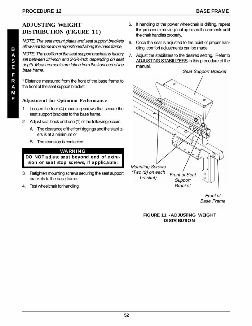
52
ADJUSTING WEIGHTDISTRIBUTION (FIGURE 11)
NOTE: The seat mount plates and seat support bracketsallow seat frame to be repositioned along the base frame.
NOTE: The position of the seat support brackets is factoryset between 3/4-inch and 2-3/4-inch depending on seatdepth. Measurements are taken from the front end of thebase frame.
* Distance measured from the front of the base frame tothe front of the seat support bracket.
Adjustment for Optimum Performance
1. Loosen the four (4) mounting screws that secure theseat support brackets to the base frame.
2. Adjust seat back until one (1) of the following occurs:
A. The clearance of the front riggings and the stabiliz-ers is at a minimum or
B. The rear stop is contacted.
WARNINGDO NOT adjust seat beyond end of extru-
sion or seat stop screws, if applicable.
3. Retighten mounting screws securing the seat supportbrackets to the base frame.
4. Test wheelchair for handling.
Mounting Screws(Two (2) on each
bracket)
Seat Support Bracket
Front ofBase Frame
Front of SeatSupportBracket
FIGURE 11 -ADJUSTING WEIGHTDISTRIBUTION
5. If handling of the power wheelchair is drifting, repeatthis procedure moving seat up in small increments untilthe chair handles properly.
6. Once the seat is adjusted to the point of proper han-dling, comfort adjustments can be made.
7. Adjust the stabilizers to the desired setting. Refer toADJUSTING STABILIZERS in this procedure of themanual.
BASE FRAMEPROCEDURE 12
BASE
FRAME

53
PROCEDURE 13RECLINER
MountingScrews
Mounting Screws(DO NOT
Overtighten)
Actuator
TieWraps
WireRetainer
LimitSwitchSensor
SeatFrame
Mounting Screws (DONOT Over Tighten)
Washers
Limit Switch Sensor
FIGURE 1 - POSITIONING LIMIT SWITCH
GasCylinder
Pivot BlockActuatorWashers
POSITIONING LIMIT SWITCH(FIGURE 1)NOTE: The battery charger connector, as well as, the limitswitch are factory set on the RIGHT side of the wheelchair.However, they can be positioned on either side for user conve-nience. The limit switch MUST BE positioned on the sameside as the battery charger connector.
1. Cut the two (2) tie wraps that secure the limit switch wireto the seat frame.
2. Remove the two (2) mounting screws and washers thatsecure the actuator to the gas cylinder pivot block.
3. Position actuator on opposite gas cylinder pivot block.
CAUTIONDO NOT over tighten the mounting screwsthat secure the actuator to the pivot block.Damage to actuator will occur.
4. Secure the actuator to the pivot block with the two (2)mounting screws and washers. DO NOT overtighten.
5. Remove the mounting screw that secures the wire re-tainer to the inside of the seat frame.
6. Remove the two (2) mounting screws and washers thatsecure the limit switch sensor to the seat frame.
7. Turn limit switch sensor over so opposite side is facing upand the wire is on the INSIDE of the seat frame.
8. Position the limit switch sensor onto the opposite side ofthe seat frame.
CAUTIONDO NOT over tighten the mounting screwsthat secure the limit switch sensor to the seatframe. Damage to the limit switch sensor willoccur.
This Procedure Includes the Following:
Positioning Limit Switch
Adjusting Limit Switch
Replacing Recliner Cable Assemblies
Replacing/Adjusting Gas Cylinders
Changing Back Height
Changing Seat Depth
Changing Seat Width
Installing/Replacing Adjustable 16 to 19-inch DeepRecliner Seat Frame onto Arrow or X Base
WARNINGAfter ANY adjustments, repair or service andBEFORE use, make sure that all attachinghardware is tightened securely - otherwiseinjury or damage may result.
9. Secure limit switch sensor to the seat frame with thetwo (2) mounting screws and washers.
10. Secure the wire retainer onto the INSIDE of the seatframe with the mounting screw.
11. Tie wrap the limit switch wire to the seat frame.
12. Adjust the limit switch. Refer to ADJUSTING LIMITSWITCH in this procedure of the manual.
ADJUSTING LIMIT SWITCH(FIGURE 2)
WARNINGNEVER operate the wheelchair while inany recline position over 105o RELATIVE TOTHE SEAT FRAME. If the limit switch doesnot stop the wheelchair from operatingin a recline position greater than 105o
RELATIVE TO THE SEAT FRAME, do not oper-ate the wheelchair. Adjust the limit switchBEFORE using the wheelchair, otherwiseinjury or damage can occur.
1. Recline the back of the wheelchair until the gas cylinderrod measures 3-21/32 of an inch.
2. Turn the power of the joystick to the ON position.
NOTE: ALL segments of the bar graph on the joystick shouldstart to flash on and off and the wheelchair should not oper-ate.
3. IF the wheelchair operates, proceed to the followingsteps to adjust the actuator on the gas cylinder pivotblock:
A. Loosen, but do not remove, the two (2) mountingscrews and washers that secure the actuator tothe gas cylinder pivot block.
RECLINER

54
FIGURE 2 - ADJUSTING LIMIT SWITCH
RECLINER
Mounting Screws and Washers(DO NOT Over-Tighten)
Actuator
Gas CylinderRod Measures3-21/32-inches
POSITION OVER105O RELATIVE
TO THE SEATFRAME
Gas CylinderPivot Block
6. Remove the operator of the existing recliner cable as-sembly from the pivot block.
7. Make sure the threads of the gas cylinder rod are flushwith the inside of the pivot block.
8. With the operator of the NEW recliner cable assem-bly on the inside of the recliner seat frame, line up themounting hole in the operator of the new recliner cableassembly with the gas cylinder rod.
CAUTIONDO NOT force the gas cylinder rod into theoperator of the recliner cable assembly.DO NOT cross thread the operator of the re-cliner cable assembly with the gas cylinder.If slack in the recliner cable or movement inthe operator of the cable assembly can notbe eliminated, DO NOT use the recliner cableassembly.
9. Screw the NEW gas cylinder into the operator of thecable assembly until the jam nut sits on the pivot block,there is no slack in the recliner cable and there is nomovement in the operator of the recliner cable as-sembly.
B. Slide actuator UP (towards top of the wheelchair).
CAUTIONDO NOT over tighten the mounting screwsthat secure the actuator to the pivotblock. Damage to the actuator will occur.
C. Only tighten the two (2) mounting screws andwashers that secure the actuator to the gas cylin-der pivot block until the actuator does not move.
D. Repeat STEPS 1 and 2 until the wheelchair doesnot operate when the gas cylinder rod is 3-21/32-inch long.
REPLACING RECLINER CABLEASSEMBLIES (FIGURE 3)NOTE: There are three (3) different cable lengths depend-ing on back height:
CABLE LENGTH BACK HEIGHTShort 18-1/2 and 20-inchesMedium 22 and 24-inchesLong 26-inches
WARNINGReplace ONE (1) recliner cable assemblyat a time to avoid injury.
1. Cut the tie wraps that secure the existing recliner cableassembly to the back cane.
2. Remove the pan screw that secures the handle ofthe existing recliner cable assembly to the back cane.
3. Loosen the jam nut on the gas cylinder rod.
4. Remove the mounting screw, washer, nylon wash-ers and locknut that secure the TOP of the gas cylin-der to the mounting bracket on the back cane.
5. Unscrew the gas cylinder from the operator of theexisting recliner cable assembly but do not removethe gas cylinder from the pivot block.
FIGURE 3 - REPLACING RECLINER CABLEASSEMBLIES
JamNut
Washer
Handle
NylonWashers
PivotBlock
Locknut
Back Cane
Gas Cylinder
Gas CylinderRod
Mounting Screw
Pan Screw
No Slackin Cable
NO Movement inOperator of the Recliner
Cable AssemblyCable Fitting
Seated Properly
Handle
CableSnappedinto Slot
CableOperator
TieWraps
Mounting Bracket
PROCEDURE 13 RECLINER

55
RECLINER PROCEDURE 13
Gas CylinderRod
Jam Nut
GasCylinder
NO Movement inOperator of the Recliner
Cable Assembly
Gas CylinderRod Threads
Handle
No Slackin Cable
FIGURE 4 - REPLACING/ADJUSTING GASCYLINDERS
HandleCable FittingSeated Properly
Pivot Block
CableSnappedinto Slot
Nylon Washer
LocknutWasher
MountingScrew
Mounting Bracket
If slack in the recliner cable or movement in the operator ofthe cable assembly can not be eliminated, DO NOT usethe recliner cable assembly.
6. Screw the NEW gas cylinder into the operator of thecable assembly until the jam nut sits on the pivot block,there is no slack in recliner cable and there is no move-ment in the operator of the recliner cable assembly.
7. Visually inspect the handle to make sure that the cableis snapped completely into slot in handle and cablefitting is seat properly in the handle.
8. Press the operator of the recliner cable assembly toextend the NEW gas cylinder.
9. Line up the mounting holes of the NEW gas cylinderand the bracket of the back cane.
10. Reinstall the mounting screw through the mountingbracket of the back cane, nylon washer, NEW gascylinder, nylon washer, mounting bracket and washerand securely tighten with the existing locknut. Torqueto 75-inch pounds.
11. Adjust the NEW gas cylinders. Refer to ADJUSTINGGAS CYLINDERS in this procedure of the manual.
RECLINER
10. Visually inspect the handle to make sure that the cable issnapped completely into slot in handle and cable fitting isseat properly in the handle.
11. Reinstall the mounting screw through the mountingbracket of the back cane, nylon washer, gas cylinder,nylon washer, mounting bracket and washer and se-curely tighten with the existing locknut. Torque to 75-inchpounds.
12. Line up the mounting hole in the handle of the reclinercable assembly with the mounting hole in the back cane.
13. Insert the pan screw through the handle of the reclinercable assembly and the back cane and torque to 9-inchpounds.
14. Tie wrap the recliner cable assembly to the recliner backcane.
15. Adjust the gas cylinder. Refer to ADJUSTING GAS CYL-INDERS in this procedure of the manual.
REPLACING/ADJUSTING GASCYLINDERS (FIGURE 4)
WARNINGReplace ONE (1) gas cylinder at a time toavoid injury.Both gas cylinders MUST be operationaland adjusted properly BEFORE using therecliner. DO NOT operate the recliner ifonly one (1) of the gas cylinders is opera-tional or adjusted properly.
Replacing Gas Cylinder
1. Remove the mounting screw, washer, nylon washersand locknut that secure the TOP of the gas cylinder tomounting bracket on back cane.
2. Loosen the jam nut on existing gas cylinder rod.
3. Unscrew the existing gas cylinder from the operator ofthe recliner cable assembly and the pivot block andremove the existing gas cylinder from the wheelchair.
4. Screw cylinder rod of the NEW gas cylinder into thepivot block until the threads of the cylinder rod are flushwith inside of pivot block (FIGURE 4).
5. With the operator of the recliner cable assembly on theinside of the recliner seat frame, line up the mountinghole in the operator of the recliner cable assembly withthe new gas cylinder rod.
CAUTIONDO NOT force the gas cylinder rod into theoperator of the recliner cable assembly.DO NOT cross thread the operator of the re-cliner cable assembly with the gas cylinder.

56
Adjusting Gas Cylinder
1. To adjust the LEFT gas cylinder: Squeeze the handle ofthe RIGHT recliner cable assembly and try to recline theback. The back should not recline.
2. If the LEFT side of the back releases without squeez-ing the handle of the LEFT recliner cable assembly,perform the following steps:
A. Finger tighten the jam nut on the rod of the gascylinder until it bottoms out on the rod of the cylin-der (FIGURE 4).
B. Turn the jam nut on the LEFT gas cylinder COUN-TERCLOCKWISE approximately one-half (1/2)revolution.
NOTE: The gas cylinder rod will turn.
C. Repeat STEP 1.
D. Repeat STEP B until the LEFT side of the backDOES NOT recline.
3. To adjust the RIGHT gas cylinder: Repeat STEPS 1and 2 for the LEFT handle of the cable assembly.
CAUTIONDamage to the gas cylinder rod WILL oc-cur if the following steps are NOT followedwhen the jam nut is torqued against thepivot block.
4. Using NO LARGER than 1/4-inch wide, fine toothedpliers, wrap masking tape around the teeth of the plierstwo (2) or (3) revolutions.
5. Using NO excessive force, hold the gas cylinder rodjust above the jam nut.
6. While holding the gas cylinder rod and using a 17mmwrench, turn the jam nut CLOCKWISE and torque theRIGHT and LEFT jam nuts against the RIGHT andLEFT pivot blocks to 156-inch pounds.
CHANGING BACK HEIGHT(FIGURE 5)1. Press the push pins on the headrest extension tubes
in and remove headrest extension from back canes.
2. Remove the recliner cables from the back canes. Re-fer to REPLACING RECLINER CABLE ASSEMBLIESin this procedure of the manual.
3. Remove the mounting screws, washers and locknutsthat secure the TOP of the gas cylinders to the mount-ing bracket on the back canes.
4. Remove the mounting screws, washers and locknutsthat secure the back canes to the seat frame.
5. Remove the existing recliner back assembly from thewheelchair.
RECLINER
FIGURE 5 - CHANGING BACK HEIGHT
MountingScrew
WashersLocknut
MountingScrew
Back Cane
SpreaderBar
NOTE: Upholstery not shown for clarity.
HeadrestExtension
Tube
PushPin
Seat Frame
MountingBracket
6. Turn the spreader bar on the existing back canesCLOCKWISE (toward back upholstery) and removethe spreader bar from the existing back canes.
7. Loosely install the spreader bar onto the NEW backcane handles by rotating the spreader bar COUN-TERCLOCKWISE (away from the back canes).
NOTE: If the spreader bar does not thread onto the backcanes, do not force. Turn the spreader bar around andrepeat STEP 7.
8. Line up two (2) bottom mounting holes of back caneswith the two (2) mounting holes in the seat frame.
WARNINGThe back canes MUST be fastened se-curely to the seat frame BEFORE using thewheelchair. Torque mounting screws to156-inch pounds.
9. Reinstall the mounting screw, washer and locknutthrough the back cane and seat frame mounting holesand torque to 156-inch pounds.
10. Reinstall the mounting screw through the mountingbracket of the back cane, nylon washer, mountinghole in the TOP of the gas cylinder, nylon washer,mounting bracket and washer and securely tightenwith the existing locknut. Torque to 75-inch pounds.
11. Reinstall the recliner cable assemblies onto the backcanes. Refer to REPLACING RECLINER CABLESin this procedure of the manual.
PROCEDURE 13 RECLINER

57
RECLINER PROCEDURE 13
RECLINER
NOTE: There are three (3) different cable lengths dependingon back height:BACK HEIGHT (in inches) 18-1/2, 20 22, 24 26
CABLE LENGTH Short Medium Long
NOTE: New recliner cables will be needed if back height ischanged to a height not within the length of the original cable.
12. Install the NEW back upholstery onto the back canes.
13. Install the ten (10) or twelve (12) mounting screws (de-pending on back height) that secure the back upholsteryto the recliner back canes.
14. Reinstall headrest extension onto recliner back canes.
15. Adjust the tautness of the back and headrest upholstery.Refer to ADJUSTING BACK OR HEADREST UPHOL-STERY in this procedure of the manual.
CHANGING SEAT DEPTH (FIGURE 6)To adjust seat depth of wheelchair, use following guidelines:
If the current seat depth is an ODD number, i.e., 17-inches,19-inches or 21-inches, the seat depth CANNOT be IN-CREASED without changing the seat frame. Refer to IN-STALLING/REPLACING ADJUSTABLE 16 TO 19-INCHDEEP RECLINER SEAT FRAME ONTO in this procedureof the manual.
If the current seat depth is an ODD number, i.e., 17-inches,19-inches or 21-inches, the seat depth can be DECREASEDby 1-inch by installing a 1-inch shorter seat pan. Refer to thefollowing procedures:
If the current seat depth is an EVEN number, i.e., *16-inches,18-inches, 20-inches or 22-inches, the seat depth CANNOTbe DECREASED without changing the seat frame. Refer toINSTALLING/REPLACING ADJUSTABLE 16 TO 19-INCHDEEP RECLINER SEAT FRAME ONTO PRONTOR2BASE FRAME in this procedure of the manual.
*NOTE: 16-inch seat depth is the smallest seat depth avail-able on recliner seat frames.
If the current seat depth is an EVEN number, i.e., 16-inches,18-inches, 20-inches or *22-inches, the seat depth can beINCREASED by 1-inch by installing a 1-inch deeper seatpan. Refer to the following procedures:
*NOTE: 22-inch seat depth is the deepest seat depth avail-able on recliner seat frames.
Hex Screws
Seat Pan
SeatFrame
FIGURE 6 - CHANGING SEAT DEPTH
Locknuts
SeatPositioning
Strap
CHANGING SEAT WIDTHTo change seat width, the seat frame must be changed tothe desired width. Refer to INSTALLING/REPLACING AD-JUSTABLE 16 TO 19-INCH DEEP RECLINER SEATFRAME ONTO PRONTOR2 BASE FRAME in this proce-dure of the manual.
NOTE: If changing the seat width of the wheelchair, theback and headrest upholstery, seat pan and cushion alsoneed to be changed.
NOTE: If changing the seat width of the wheelchair, the backcanes, spreader bar and headrest pillow may also need tobe changed. Refer to the following charts:
BACK CANES AND SPREADER BAR SEAT WIDTHRANGES
14-17-INCHES OR 18-24-INCHES
HEADREST PILLOWS SEAT WIDTH RANGES (ININCHES)
14-15, 16-18, 19-20 OR 21-24
Seat Pan Removal/Replacement Procedures:
1. Remove the seat cushion from the wheelchair.
2. Remove the six (6) mounting screws and locknuts thatsecure seat pan, seat positioning strap to the seat frame.
3. Install new 1-inch deeper/shorter seat pan onto seatframe.
4. Reinstall the mounting screws, spacers and locknutsand torque to 75-inch pounds.
5. Remove the protective strips on the seat pan and rein-stall the seat cushion onto the seat pan.
NOTE: Clean upholstery with a warm damp cloth and milddetergent to remove superficial soil.
WARNINGLaundering or moisture will reduce the flameretardation of the upholstery.

58
If the seat width required is within the range of the origi-nal back canes, spreader bar and headrest pillow, theoriginal components can still be used.
If the seat width required is NOT within the range of theoriginal back canes, spreader bar and headrest pillow,the original components can not be used.
EQUIPMENT OPTION
INSTALLING/REPLACINGADJUSTABLE 16 TO 19-INCHDEEP RECLINER SEAT FRAME(FIGURE 7)1. Perform one (1) of the following in PROCEDURE
7 of this manual:
A. Remove standard seat. Refer to REMOVING/INSTALLING STANDARD SEAT in PROCE-DURE 6 of this manual.
B. Remove Captain's van seat. Refer to INSTALL-ING/REMOVING CAPTAIN'S VAN SEAT inPROCEDURE 6 of this manual.
2. Remove seat pan on recliner.
3. Install new recliner seat assembly onto seat mount-ing plates.
4. Secure recliner seat assembly to seat mountingplates with the mounting screws, spacers (16-inchwide only) and locknuts. Torque the mounting screwsto 156-inch pounds.
NOTE: There are two (2) types of seat mounting plates;low and high heights. The seat mount plate shown in thisillustration represents the medium height. Refer toMOUNTING PLATE - SEAT ANGLE ADJUSTMENTAND INSTALLATION ORIENTATION in PROCEDURE6 of this manual for illustrations of the low and high heights.
5. Position limit switch onto wheelchair. Refer to PO-SITIONING LIMIT SWITCH in this procedure of themanual.
6. Reinstall recliner seat pan with existing six (6) mount-ing screws.
7. Install battery box(es). Refer to INSTALLING/RE-MOVING BATTERY BOXES in PROCEDURE 11of this manual.
8. Install shrouds. Refer to INSTALLING SHROUDS inPROCEDURE 10 of this manual..
RECLINER
FIGURE 7 - INSTALLING/REPLACINGADJUSTABLE 16 TO 19-INCH DEEP RECLINER
SEAT FRAME
MountingScrews
BaseFrame
Spacers(16-inch
wideonly)
ReclinerSeat Assembly
Seat MountPlate
Locknuts
PROCEDURE 13RECLINER

59
LIMITED WARRANTYPLEASE NOTE: THE WARRANTY BELOW HAS BEEN DRAFTED TO COMPLY WITH FEDERAL LAWAPPLICABLE TO PRODUCTS MANUFACTURED AFTER JULY 4, 1975.
This warranty is extended only to the original purchaser/user of our products.
This warranty gives you specific legal rights and you may also have other legal rights whichvary from state to state.
With regards to the original purchaser/user only, Invacare warrants the side frames to befree from defects in materials and workmanship for a period of five (5) years from date ofpurchase; electronics for a period of one (1) year from the date of purchase; motors andgearboxes for a period of eighteen (18) months for Pronto models with motors that havemotor locks and a period of twelve (12) months for Pronto models with motors that haveclutches from the date of purchase; all remaining components (including gas cylinders forrecliners) for one (1) year from the date of purchase except upholstered materials, paddedmaterials and tires/wheels. If within such warranty period any product shall be proven to bedefective, such product shall be repaired or replaced, at Invacare's option. This warrantydoes not include any labor or shipping charges incurred in replacement part installation orrepair of any such product. Invacare's sole obligation and your exclusive remedy under thiswarranty shall be limited to such repair and/or replacement.
For warranty service, please contact the dealer from whom you purchased your Invacareproduct. In the event you do not receive satisfactory warranty service, please write directlyto Invacare at the address on the bottom of the back cover. Provide dealer's name ad-dress, date of purchase, indicate nature of the defect and, if the product is serialized,indicate the serial number. Do not return products to our factory without our prior consent.
LIMITATIONS AND EXCLUSIONS: THE FOREGOING WARRANTY SHALL NOT APPLY TO SERIAL NUM-BERED PRODUCTS IF THE SERIAL NUMBER HAS BEEN REMOVED OR DEFACED, PRODUCTS SUB-JECT TO NEGLIGENCE, ACCIDENT, IMPROPER OPERATION, MAINTENANCE OR STORAGE, COM-MERCIAL OR INSTITUTIONAL USE, PRODUCTS MODIFIED WITHOUT INVACARE'S EXPRESS WRIT-TEN CONSENT INCLUDING, BUT NOT LIMITED TO, MODIFICATION THROUGH THE USE OF UNAU-THORIZED PARTS OR ATTACHMENTS; PRODUCTS DAMAGED BY REASON OF REPAIRS MADE TOANY COMPONENT WITHOUT THE SPECIFIC CONSENT OF INVACARE, OR TO A PRODUCT DAM-AGED BY CIRCUMSTANCES BEYOND INVACARE'S CONTROL, AND SUCH EVALUATION WILL BESOLELY DETERMINED BY INVACARE. THE WARRANTY SHALL NOT APPLY TO PROBLEMS ARISINGFROM NORMAL WEAR OR FAILURE TO ADHERE TO THESE INSTRUCTIONS. A CHANGE IN OPERAT-ING NOISE, PARTICULARLY RELATIVE TO MOTORS AND GEARBOXES DOES NOT CONSTITUTE AFAILURE. ALL SUCH DEVICES WILL EXHIBIT A CHANGE IN OPERATING NOISE DUE TO AGING.
THE FOREGOING WARRANTY IS EXCLUSIVE AND IN LIEU OF ALL OTHER EXPRESS WARRANTIES.IMPLIED WARRANTIES, IF ANY, INCLUDING THE IMPLIED WARRANTIES OF MERCHANTABILITYAND FITNESS FOR A PARTICULAR PURPOSE, SHALL NOT EXTEND BEYOND THE DURATION OF THEEXPRESSED WARRANTY PROVIDED HEREIN AND THE REMEDY FOR VIOLATIONS OF ANY IMPLIEDWARRANTY SHALL BE LIMITED TO REPAIR OR REPLACEMENT OF THE DEFECTIVE PRODUCT PUR-SUANT TO THE TERMS CONTAINED HEREIN. INVACARE SHALL NOT BE LIABLE FOR ANY CONSE-QUENTIAL OR INCIDENTAL DAMAGES WHATSOEVER.
THIS WARRANTY SHALL BE EXTENDED TO COMPLY WITH STATE/PROVINCIAL LAWS AND REQUIRE-MENTS.
WARRANTY
WARRANTY

!
"#$%& '#("!)$ *+& ,-./0" (0+& 1 ( 2&%0 $$$$'3%( 4
5/// 1 ( 66/7895:5, ,7-%";//977798-// -/,9;-/9;;7; ! //9;,( :/-;7:,<:=9/6>//