
Quick Start Guide - Amazon Web...
36
3 rd Generation Personal 3D Printer Quick Start Guide See Inside for Use and Safety Information The USB Mass Storage Device Contains the User Guide and Quick Start Guide in other Languages
Transcript of Quick Start Guide - Amazon Web...

3rd GenerationPersonal 3D Printer
Quick Start GuideSee Inside for Use and Safety Information
The USB Mass Storage Device Contains the User Guide and Quick Start Guide in other Languages


Congratulations on the purchase of your new Cube® 3D Printer! This Quick Start Guide has the use and safety information you need to get started. Welcome to the 3D creative revolution – let the possibilities begin!
If you have any questions, do not hesitate to reach us at [email protected].
This Quick Start Guide will give you basic instructions on how to get your Cube® 3D Printer connected to power and printing so you can start making your own creations.
For more detailed instructions, refer to the Cube® User Guide located on your USB mass storage device.
SAFETY ........................................................................................................................ 1
YOUR CUBE AT A GLANCE ........................................................................................ 2 Operating Environment ..............................................................................................................2
UNPACK YOUR CUBE ................................................................................................. 3 What’s Included ..........................................................................................................................6
SETTING UP AND ACTIVATING YOUR CUBE ........................................................... 7
FINISHING YOUR CREATION ................................................................................... 24 Removing your Creation from the Print Pad ..........................................................................24
Removing Rafts ........................................................................................................................24
Removing Sidewalks ................................................................................................................25
Removing Supports .................................................................................................................25
MAINTENANCE .......................................................................................................... 26 Print Pad Maintenance .............................................................................................................26
Gap Verification ........................................................................................................................28
Manual Gap Adjustment ..........................................................................................................30
Recover A Cartridge .................................................................................................................31

1
SAFETY
HOT SURFACE HAZARD: A HOT SURFACE IS ACCESSIBLE IN THE VICINITY OF THIS SIGN OR AT THE PRINT JET. AVOID CONTACT WITH THESE AREAS. HOT SURFACES CAN CAUSE SEVERE BURNS.
Caution: Indicates something may happen that could cause loss of data, damage to equipment, or could cause personal injury.
Caution: Indicates a pinch point hazard that could cause personal injury.
• Follow all safety rules in this section and observe all cautions and warnings in this guide.
• DO NOT modify any safety features or make modifications to the Cube. Doing so is prohibited and voids your warranty.
• Use of print materials other than 3D Systems print materials and genuine 3D Systems components may void warranty.
• Adult supervision is required; observe children closely and intervene as necessary to prevent potential safety problems and ensure the appropriate use of the Cube. Ensure small 3D prints are not accessible to young children. These 3D prints are potential choking hazards for young children.
• DO NOT change a material cartridge during printing; doing so may damage the Cube.
WARNING: DO NOT TOUCH THE PRINT JETS DURING SETUP AND OPERATION. THE PRINT JETS BECOME VERY HOT.
Caution: DO NOT unplug the Cube while the print jet is hot. Refer to the touchscreen to determine when the print jets are cool enough.
CAUTION: Read and follow all instructions prior to setting up the printer.
To ensure safety, please exercise caution when operating your printer. Read and follow all safety precautions as outlined in this document and the Cube User Guide. Be careful when operating your Cube 3D Printer to ensure proper printing and be mindful of and avoid hot surfaces.

2
YOUR CUBE AT A GLANCE
OPERATING ENVIRONMENT• Room Temperature: 16˚ - 29˚C (60˚ - 85˚F)
• Non-condensing relative humidity: 30% - 60%
BA Print Jets
B Print Jet Tubes
C Material Cartridges
D Print Pad
E Print Platform
F Touchscreen Display
G On / Off Button
H USB Inlet Port (mass storage device only)
I Power Inlet
J Purge Bins with Wipers
K USB B Port (for future use)
B
C CD E
F G
K
H I
H
A
J
K
I

3
UNPACK YOUR CUBE
NOTE: Keep all packing materials for future transport. Shipping the printer without the original packing materials may damage the printer and void the manufacturer’s warranty.
1. Pull the clips (A) and remove them from the top of the printer box and open the box.
2. Remove the upper foam support.
3. Remove the printer from the box and remove the protective bag from the printer. Place the printer on a solid, level base.
NOTE: When installing the printer there must be a minimum of 8” (203 mm) of space on top and on either side of the printer.
NOTE: There must be a minimum of 4” (102 mm) space in front of and behind the printer.
A

4
8” (203 mm)
8” (203 mm
)8” (2
03 m
m)
Hand Clearance Around the Printer Build Plate Travel Area
4” (102 mm)
4” (102 mm)
Back
Front
Front View Top View
4. Remove the top insert.
5. Fold the sides inward and remove the lower insert from the printer.

5
9. Raise the print platform (A) and remove the spacer (B) from the printer.
10. Open the accessories box and unpack the material cartridges, the USB mass storage device, the power supply, cord, and the Cube Glue bottle.
11. Connect the power supply cable to the power inlet port (A) on the printer.
NOTE: The cable should lock in place. To remove the cable, pull back on the outer cable end and carefully pull it out from the printer.
12. Connect the power cord to utility power and to the power supply.
NOTE: Ensure the connection is secure.
13. Power on the printer by pressing the button (A) next to the touchscreen display.
A
A
B
A

6
WHAT’S INCLUDED
1Depending on your printer model or configuration, up to two cartridges may be included.
NOTE: The sandpaper should only be used for lightly sanding the print pad when prompted by the touchscreen display. It should not be used for sanding parts. For more information, refer to the section titled Print Pad Maintenance.
NOTE: *The User Guide can be found on your USB mass storage device.
NOTE: The appearance of some components may vary.
Power Supply Power Cord Quick Start Guide
Removable Print Pad Cartridges1Cube Cube Glue
Casing and Contents
Pliers Scraper
cubi
fy.co
m
USB Mass Storage Device*
1.5 mm Allen Wrench
Gap Gauge SandpaperCasing

7
SETTING UP AND ACTIVATING YOUR CUBE
1. Select your language. Press the checkmark to confirm your selection.
NOTE: The selected language will be indicated.
2. Enter a name for your printer. Scroll through the letters by pressing the arrow symbols on each side of the screen. Select the letters to spell out the name. Select the checkmark to confirm your choice. You can change the name at any time by navigating to the System 1 screen and selecting CUBE NAME.
NOTE: The abc button toggles between lowercase letters, uppercase letters and numerals.
NOTE: The printer will begin to search for area networks.
8
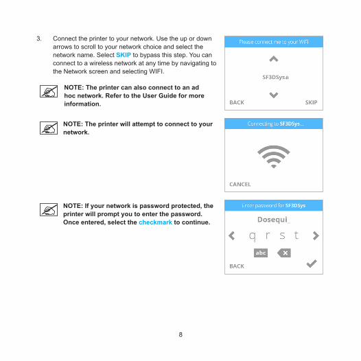
3. Connect the printer to your network. Use the up or down arrows to scroll to your network choice and select the network name. Select SKIP to bypass this step. You can connect to a wireless network at any time by navigating to the Network screen and selecting WIFI.
NOTE: The printer can also connect to an ad hoc network. Refer to the User Guide for more information.
NOTE: The printer will attempt to connect to your network.
NOTE: If your network is password protected, the printer will prompt you to enter the password. Once entered, select the checkmark to continue.

9
NOTE: The display will indicate when the network connection has been made.
NOTE: If the wrong password was entered, you will be asked to enter the password again after a few seconds.
NOTE: Connection to a network is confirmed by a checkmark to the left of the network name. If the network is secured, a lock icon will appear to the right of the network name.

10
4. Select the checkmark to continue to the registration and warranty activation process.
5. Log in to Cubify.com. Go to www.cubify.com, select My Cubify and log in to your account.
NOTE: If you have not activated an account on Cubify.com, select SIGN UP and follow the instructions.
6. Go to www.cubify.com/activate.

11
NOTE: The serial number for your printer will appear on the printer’s touchscreen display. Take note of the serial number. You will need the serial number to activate your printer.
7. Select the checkmark to continue.
NOTE: This illustration provides an example of a serial number. Do not use this number to activate your printer.
8. Enter your serial number twice and select ACTIVATE.
NOTE: Your 4-digit activation code will appear. Please make note of the activation code. You will need to enter it into the printer’s touchscreen display to activate the printer.
NOTE: You can access the user guide, Cubify software, and creations.

12
9. Enter the 4-digit activation code into the printer and select the checkmark to continue.
10. Select the checkmark to complete the registration and warranty activation process.
11. Before installing cartridges, select the cartridge icon or select START to begin the process of installing your print cartridge.

13
NOTE: The printer will begin to heat. Wait until the printer has finished heating and then follow the user prompts in the touchscreen menu.
12. Insert the print jet (from the cartridge that will be mounted on the left side of the printer) into the left print jet opening on top of the printer. Rotate the print jet clockwise until the dots align.
NOTE: As you rotate the print jet, ensure the print jet tube is tucked under the top of the printer cover.
13. Select the checkmark to continue.
14. Mount the cartridge on the left side of the printer and select the checkmark to continue.

14
NOTE: The print jet will begin to heat. Once the print jet has reached the operating temperature, the printer will prime melted material into the refuse bin.
15. The left cartridge has been installed. Select the checkmark to continue.
NOTE: The printer will begin to heat. Wait until the printer has finished heating and then follow the user prompts in the touchscreen menu.

15
16. Insert the print jet (from the cartridge that will be mounted on the right side of the printer) into the right print jet opening on top of the printer. Rotate the print jet clockwise until the dots align.
NOTE: As you rotate the print jet, ensure the print jet tube is tucked under the top of the printer cover.
17. Select the checkmark to continue.
18. Mount the cartridge on the right side of the printer and select the checkmark to continue.
NOTE: The print jet will begin to heat. Once the print jet has reached the proper temperature, the printer will prime melted material into the refuse bin.

16
19. The right cartridge has been installed. Select the checkmark to continue.
20. Select PRINT to continue.
21. It is recommended that Auto Level is performed prior to the first print. Ensure the print pad is clean and installed properly and then select the checkmark to continue to Auto Level.
NOTE: When installed properly, the print pad magnetically attaches to the adjustment knobs.

17
NOTE: The printer will begin the Auto Level procedure. This may take a few minutes.
22. Select the checkmark to continue.
NOTE: If the print pad is not level, remove the print pad and select the checkmark to continue. The print pad is magnetically attached to the adjustment knobs. To remove it, lift up the front of the print pad and pull it out of the printer.

18
NOTE: Follow the instructions on the touchscreen display. Use the included 1.5 mm Allen wrench to loosen the lock screws before turning the knobs. Select the checkmark to continue.
NOTE: The lock screw for knob A can be accessed from behind the printer. The lock screw for knob B can be accessed from the front of the printer.
NOTE: Follow the instructions on the touchscreen display. After the adjustments have been made, select the checkmark to continue.
NOTE: When prompted, tighten the lock screw enough to ensure the adjustment knob does not easily turn. Select the checkmark to perform Auto Level again.

19
23. Install the print pad and select the checkmark to perform Auto Gap.
NOTE: To install the print pad, place it on top of the adjustment knobs. When the print pad is centered properly, magnets will secure the print pad to the adjustment knobs.
NOTE: The printer will perform an automated gap measurement.
24. Select the checkmark to continue.
NOTE: The value presented on the touchscreen display is the absolute print pad position. Note and refer to this value when performing the Manual Level procedure. Your number may differ from the illustration.

20
NOTE: If Auto Gap is not successful, it is recommended that you perform Auto Level and Auto Gap again. Select AUTO LEVEL to continue.
NOTE: If Auto Gap is not successful the second time, select PLATE MAINTENANCE. For more information, refer to the section titled PRINT PAD MAINTENANCE. Once the PLATE MAINTENANCE procedure has been performed, perform Auto Level and Auto Gap.
NOTE: If Auto Gap is still not successful, select MANUAL GAP ADJUSTMENT. Refer to the section titled Manual Gap Adjustment for more information. Once the Manual Gap Adjustment has been performed, note the final reading for future reference.
25. Select PRINT.

21
NOTE: If the color built into the test print does not match a color of one of the installed print cartridges, the printer will assign an installed cartridge color to the test print. Select the checkmark to continue.
26. Gently squeeze the bottle and apply two thin layers of Cube Glue to the print pad. Select the checkmark to continue.
NOTE: Apply enough glue to cover a square area of 5” (15 cm).
NOTE: For best results, apply two thin layers of Cube Glue using slow, circular motions.
NOTE: Allow the glue to dry before printing.
NOTE: The print jets will begin to heat and then begin printing the welcome message test print.

22
27. Select the checkmark to go to the main menu.
NOTE: You may also press and release the button next to the touchscreen display to return to the main menu.

23
Function ChecklistIf you skip or exit from a function during the printer setup sequence below, that function can be performed at any time using the utilities in the printer menu.
LANGUAGE
CUBE NAME
WIFI
ACTIVATE PRINTER
INSTALL CARTRIDGES
AUTO LEVEL
TEST PRINT
√

24
FINISHING YOUR CREATION
REMOVING YOUR CREATION FROM THE PRINT PAD1. Remove the print pad and place it in a container filled with warm tap water. Allow it to soak for
approximately ten minutes or until your creation can be easily removed from the print pad. After it has soaked, gently pry the creation from the print pad using the included scraper.
Caution: Always move the scraper away from the body. The scraper can cause injury if not used correctly.
Caution: Exercise caution when using a tool to remove a part from the print pad. The print pad can become damaged if the tool is not used properly.
2. Clean the glue from the print pad by rinsing it under tap water.
3. Dry the print pad with a lint-free cloth.
REMOVING RAFTSA raft is the flat support structure attached to the base of your creation. You can enable this option in your Cubify application before generating a print file. Although it is recommended that parts are generated and printed without rafts, some larger, more complicated parts may require one.
ABS Raft / PLA Part ABS rafts can be peeled away from PLA parts.
PLA Raft / ABS Part PLA rafts can be pulled from ABS parts.
ABS Raft / ABS Part Use pliers to pull away as much of the raft as possible. Then use a rough-grade sandpaper to remove the remaining raft material, followed by a fine-grade wet and dry sandpaper to achieve a smoother finish.
PLA Raft / PLA Part Use pliers to pull away as much of the raft as possible. Then use a rough-grade sandpaper to remove the remaining raft material, followed by a fine-grade wet and dry sandpaper to achieve a smoother finish.

25
REMOVING SIDEWALKSA sidewalk is a mesh boundary that prints around the outside diameter of the part. Its main purpose is to reduce the tendency of warping especially when printing flat parts with ABS material. They are not recommended for parts that have fine details.
Sidewalks are designed to easily break away from a part once it has been removed from the print pad.
REMOVING SUPPORTSSupports are used when printing creations that need a supporting structure to print properly.
When using PLA or ABS as a support material, peel the supports away from the part. Then, using wire cutters, cut away the support structure from your creation. Once the supports have been cut away, use fine-grade sandpaper (not included) to finish smoothing the part.
When using Infinity Rinse-Away™ support material, run warm water over the part until the part can be removed from the print pad. Submerge the part in warm water until the supports begin to soften. Pull the supports away from the part using pliers (supplied). With most of the support material removed, use a blunt-edged pick or toothbrush to remove residual support material from holes and crevices. To remove support material from moving parts or areas that are difficult to reach, it is recommended that the part is allowed to soak in water for several hours. Then, rinse the part under running warm water to ensure all supports have been removed.

26
MAINTENANCE
PRINT PAD MAINTENANCEAuto Level and Auto Gap can be affected by a residual glue or print material adhered to the print pad. These procedures can also be affected by a print pad that is too shiny. Remove all glue and print material from the print pad before performing Print Pad Maintenance.
1. Select PLATE MAINTENANCE.
2. Remove the print pad. Lift up the front of the print pad and pull it out of the printer.
NOTE: The print pad is magnetically attached to the adjustment knobs.
3. Using the included fine-grit sandpaper, lightly buff the print pad.
NOTE: Refer to the section titled Clean The Print Pad for specific instructions.
NOTE: Ensure the print pad is clean and dry before installing it in the printer.
4. Select the checkmark to continue.
5. Perform the Auto Level and Auto Gap procedures.

27
Clean The Print Pad1. Remove the print pad from the printer.
2. Wash all glue and print material from the print pad with warm tap water. If necessary, scrub the print pad with a soft brush.
3. Dry the print pad thoroughly.
4. If residual print material is still adhered to the print pad, gently use the scraper to remove it. Refer to the User Guide for more information.
5. If portions of the print pad appear shiny, buff the surface (with very light pressure on the included sandpaper) left-to-right in .5” (12.7 mm) swirling motions until the entire print pad has been treated.
NOTE: It is most important to lightly sand all shiny parts of the print pad so the print pad surface appears matte in texture.
6. Clean and dry the print pad thoroughly.
7. Reinstall the print pad with the Cube symbol (A) on the print pad oriented to the front and aligned with the Cube symbol (B) on print platform.
8. Perform the Auto Level and Auto Gap Procedures.
A
B

28
GAP VERIFICATIONAfter the welcome message test print has printed and has been removed from the print pad, visually inspect the first (bottom) layer of the print and verify the quality. Turn the print upside down and inspect the printing grain.
Correct GapThe gap is correct when the bottom of the print appears smooth and the lines are tightly fused together.

29
Gap Is Too LargeIf the lines are more prominent (see the illustration below) and not tightly fused, the gap is too large. Auto Level and Auto Gap should be performed.
If the first layer begins to fray when removing the print from the print pad, the gap is too large.
Gap Is Too NarrowWhen the gap is too narrow, the part may be very difficult to remove from the print pad. In addition, the bottom layers may break off from the rest of the part while removing it. The bottom of the first layer will appear very smooth and shiny with almost no visible lines.
NOTE: If the bottom of the part appears shiny, make sure all glue has been removed and then reinspect it.
Caution: Damage to the print pad can occur if the gap is too narrow.

30
MANUAL GAP ADJUSTMENTIf Auto Gap is unsuccessful, you may perform a manual gap adjustment to ensure the first layer of the part prints properly.
1. Select MANUAL GAP ADJUSTMENT.
2. Place the gap gauge on top of the print pad under the left print jet. Select the checkmark to continue.
NOTE: Ensure the left cartridge is installed before performing this procedure.
NOTE: The Gap Gauge is a thin polyester strip approximately 8.5” (216 mm) long and 1.5” (38 mm) wide.
3. Gently slide the gap gauge back and forth between the print pad and the left print jet. Using the arrows, raise or lower the print pad until you feel a slight resistance on the gauge. Select the checkmark when you feel the proper resistance.
Caution: Exercise caution to prevent the print jet from pressing into the print pad. Once you feel a slight resistance in the Gap Gauge as it moves between the print pad and the left print jet, the gap is correct.

31
RECOVER A CARTRIDGEUse the PURGE JETS utility to recover a print cartridge. If you do not have the door on your cartridge and need to recover it, contact Cubify Support.
The cartridge must be properly installed in the printer before performing the procedure. Refer to the user guide for more information.
1. Carefully open the cartridge door and remove it from the cartridge.
2. Select SETUP on the touchscreen.
3. Navigate to the PRINT JET CALIBRATION screen and select PURGE JETS.
4. On the touchscreen, select the print jet you would like to purge. Select the checkmark to continue.
5. Using the pliers from the tool kit, carefully pull down the material sleeve.
Caution: Do not pinch or twist the material sleeve.
6. Using the pliers, grasp the print material just above the sleeve and push the material upward.
NOTE: The upward pressure will allow the feeder to engage the print material.
7. Continue to push the print material upward until the print jet begins purging.


3D Systems, Inc.
333 Three D Systems Circle | Rock Hill, SC | 29730
www.Cubify.com
©2015 3D Systems, Inc. All rights reserved.
The 3D Systems logo, 3D Systems, Cube and Cubify are registered trademarks of 3D Systems, Inc.
PN: 390186-00 Rev. F


![CUBE-BL-JP-18 CUBE-PK-JP-18 CUBE-YL-JP-18 (JP) …...CUBE-BL-JP-18 CUBE-PK-JP-18 CUBE-YL-JP-18 (JP) 1.2 Litre Capacity [JP] Operating Guide (JP)Please read this entire guide before](https://static.fdocuments.in/doc/165x107/5f0aa9a57e708231d42cb922/cube-bl-jp-18-cube-pk-jp-18-cube-yl-jp-18-jp-cube-bl-jp-18-cube-pk-jp-18-cube-yl-jp-18.jpg)
