I yam what I yam, and that’s all I yam… I’m Popeye the Sailor Man! POPEYE

B
Digital Sound Projector
Quick Reference Guide
SWK-W16
For more detailed information, refer to the Owner’s Manual on the CD-ROM.Caution: Do not attempt to play this CD-ROM in an audio player.

2 En
1 To assure the finest performance, please read this manual carefully. Keep it in a safe place for future reference.
2 Install this sound system in a well ventilated, cool, dry, clean place - away from direct sunlight, heat sources, vibration, dust, moisture, and/or cold. For proper ventilation, allow the following minimum clearances.
Top: 5 cm, Rear: 5 cm, Sides: 5 cm3 Locate this unit away from other electrical appliances, motors, or transformers to avoid humming
sounds.
4 Do not expose this unit to sudden temperature changes from cold to hot, and do not locate this unit in an environment with high humidity (i.e. a room with a humidifier) to prevent condensation inside this unit, which may cause an electrical shock, fire, damage to this unit, and/or personal injury.
5 Avoid installing this unit where foreign object may fall onto this unit and/or this unit may be exposed to liquid dripping or splashing. On the top of this unit, do not place:– Other components, as they may cause damage and/or discoloration on the surface of this unit.– Burning objects (i.e. candles), as they may cause fire, damage to this unit, and/or personal
injury.– Containers with liquid in them, as they may fall and liquid may cause electrical shock to the
user and/or damage to this unit.
6 Do not cover this unit with a newspaper, tablecloth, curtain, etc. in order not to obstruct heat radiation. If the temperature inside this unit rises, it may cause fire, damage to this unit, and/or personal injury.
7 Do not plug in this unit to a wall outlet until all connections are complete.
8 Do not operate this unit upside-down. It may overheat, possibly causing damage.
9 Do not use force on switches, knobs and/or cords.
10 When disconnecting the power cable from the wall outlet, grasp the plug; do not pull the cable.
11 Do not clean this unit with chemical solvents; this might damage the finish. Use a clean, dry cloth.
12 Only voltage specified on this unit must be used. Using this unit with a higher voltage than specified is dangerous and may cause fire, damage to this unit, and/or personal injury. Yamaha will not be held responsible for any damage resulting from use of this unit with a voltage other than specified.
13 Be sure to connect to an appropriate outlet with a protective grounding connection. Improper grounding can result in electrical shock, damage to the device(s), or even fire.
14 To prevent damage by lightning, keep the power cable and outdoor antennas disconnected from a wall outlet or this unit during a lightning storm.
15 Do not attempt to modify or fix this unit. Contact qualified Yamaha service personnel when any service is needed. The cabinet should never be opened for any reasons.
16 When not planning to use this unit for long periods of time (i.e. vacation), disconnect the AC power plug from the wall outlet.
17 Be sure to refer to the “Troubleshooting” section of the Owner’s Manual on the CD-ROM for common operating errors before concluding that this unit is faulty.
18 Before moving this unit, press A to set it to standby mode and disconnect the AC power plug from the wall outlet.
19 Condensation will form when the surrounding temperature changes suddenly. Disconnect the power cable from the outlet, then leave this unit alone.
20 When using this unit for a long time, this unit may become warm. Turn the power off, then leave this unit alone for cooling.
21 Install this unit near the AC outlet and where the AC power plug can be reached easily.
22 The batteries shall not be exposed to excessive heat such as sunshine, fire or the like. When you dispose of batteries, follow your regional regulations.
23 Excessive sound pressure from earphones and headphones can cause hearing loss.
24 Keep the product out of reach of children to avoid them swallowing small parts.
CAUTION: READ THIS BEFORE OPERATING YOUR UNIT.
This unit is not disconnected from the AC power source as long as it is connected to the wall outlet, even if this unit itself is turned off by A. This state is called the standby mode. In this state, this unit is designed to consume a very small quantity of power.
WARNINGTO REDUCE THE RISK OF FIRE OR ELECTRIC SHOCK, DO NOT EXPOSE THIS UNIT TO RAIN OR MOISTURE.
Do not use this unit within 22 cm of persons with a heart pacemaker implant or defibrillator implant.
Radio waves may affect electro-medical devices.Do not use this unit near medical devices or inside medical facilities.
The name plate for SWK-W16 is located on the bottom of the unit.
We, Yamaha Music Europe GmbH hereby declare that this unit is in compliance with the essential requirements and other relevant provisions of Directive 1999/5/EC.
Yamaha Music Europe GmbH Siemensstr. 22-34 25462 Rellingen, GermanyTel: +49-4101-303-0

En 3
■ Notes on remote controls and batteries• Do not spill water or other liquids on the remote control.• Do not drop the remote control.• Do not leave or store the remote control in the following conditions:
– places of high humidity, such as near a bath– places of high temperatures, such as near a heater or stove– places of extremely low temperatures– dusty places
• Insert the battery according to the polarity markings (+ and -).• Change all batteries if you notice the following conditions:
– the operation range of the remote control narrows• If the batteries run out, immediately remove them from the remote control to prevent an explosion or
acid leak.• If you find leaking batteries, discard the batteries immediately, taking care not to touch the leaked
material. If the leaked material comes into contact with your skin or gets into your eyes or mouth, rinse it away immediately and consult a doctor. Clean the battery compartment thoroughly before installing new batteries.
• Do not use old batteries together with new ones. This may shorten the life of the new batteries or cause old batteries to leak.
• Do not use different types of batteries (such as alkaline and manganese batteries) together. Danger of explosion may happen if batteries are incorrectly replaced. Specification of batteries may be different even though they look the same.
• Before inserting new batteries, wipe the compartment clean.• Keep batteries away from children. If a battery is accidentally swallowed, contact your doctor
immediately.• When not planning to use the remote control for long periods of time, remove the batteries from the
remote control.• Do not charge or disassemble the supplied batteries.
■ For U.K. customersIf the socket outlets in the home are not suitable for the plug supplied with this appliance, it should be cut off and an appropriate 3 pin plug fitted. For details, refer to the instructions described below.
The plug severed from the mains lead must be destroyed, as a plug with bared flexible cord is hazardous if engaged in a live socket outlet.
■ Special Instructions for U.K. Model
Information for Users on Collection and Disposal of Old Equipment and Used BatteriesThese symbols on the products, packaging, and/or accompanying documents mean that used electrical and electronic products and batteries should not be mixed with general household waste.For proper treatment, recovery and recycling of old products and used batteries, please take them to applicable collection points, in accordance with your national legislation and the Directives 2002/96/EC and 2006/66/EC.By disposing of these products and batteries correctly, you will help to save valuable resources and prevent any potential negative effects on human health and the environment which could otherwise arise from inappropriate waste handling.For more information about collection and recycling of old products and batteries, please contact your local municipality, your waste disposal service or the point of sale where you purchased the items.
[Information on Disposal in other Countries outside the European Union]These symbols are only valid in the European Union. If you wish to discard these items, please contact your local authorities or dealer and ask for the correct method of disposal.
Note for the battery symbol (bottom two symbol examples):This symbol might be used in combination with a chemical symbol. In this case it complies with the requirement set by the Directive for the chemical involved.
Note
IMPORTANTTHE WIRES IN MAINS LEAD ARE COLOURED IN ACCORDANCE WITH THE FOLLOWING CODE:
Blue: NEUTRALBrown: LIVE
As the colours of the wires in the mains lead of this apparatus may not correspond with the coloured markings identifying the terminals in your plug, proceed as follows:The wire which is coloured BLUE must be connected to the terminal which is marked with the letter N or coloured BLACK. The wire which is coloured BROWN must be connected to the terminal which is marked with the letter L or coloured RED.Making sure that neither core is connected to the earth terminal of the three pin plug.
To view the Owner’s Manual, click on “English” in the screen displayed automatically when you insert the CD-ROM into your PC, or click on the model name if the screen to select models is displayed, and then click on “English” in the next screen. Then, follow the onscreen instructions.If the screen is not displayed automatically, open the “index.html” in the CD-ROM.The Owner’s Manual contained in the CD-ROM can be downloaded from the following website: URL : http://download.yamaha.com/

4 En Supplied accessories
Before connecting, make sure you have received all of the following items.
* The shape of the power cable plug varies depending on where the unit was purchased.
Before installing batteries or using the remote control, be sure to read battery and remote control precautions in this booklet.
About this Quick Reference Guide
The Quick Reference Guide provides instructions for connecting a TV and BD/DVD player to the unit, applying settings, and playing content. For more information on operations, refer to the Owner’s Manual in the supplied CD-ROM.
Read the safety instructions described in this booklet before using the unit. For instructions on how to operate or set the external devices, refer to documentation supplied with each device.
• indicates supplementary explanations for better use.
• indicates precautions for use of the unit and its feature limitations.
Supplied accessories
Remote control Batteries(AAA, R03, UM-4) (x2)
Optical cable (1.5 m)
Power cable (2 m)* IntelliBeam microphone (6 m)
Cardboard microphone stand
Stands (x2) Screws (For the stands; x2) Subwoofer cable (3 m)
System control cable (3 m)
• Owner’s Manual CD-ROM
• Quick Reference Guide (this booklet)
• MusicCast Setup Guide
Devices and cables required for connection
• TV • BD/DVD player • HDMI cables (x2)
Preparing remote control
Installing the batteries
Operation range
Battery × 2(AAA, R03, UM-4)
Press down on the arrow and slide the cover in the direction in which it points.
Slide the cover back to close it.
Within 6 m

a Installation En 5
This unit reflects sound beams off of walls and a ceiling to create the surround sound effect. The position of this unit in relation to the listening position, walls, and a ceiling is important to achieving the desired surround sound effects. Refer to pages 5 to 7 when installing the unit. When installing this unit on a rack behind which there is limited space, for example, it may be easier to connect external devices to this unit first. This will depend upon the installation location. See page 8 for information regarding the connection of external devices.
a Installation
Notes• Be sure to install this unit on a large, stable stand where it does not fall subject to vibrations, such as from an earthquake, and where it is out of the reach of children.
• There is a built-in antenna on the top of the unit. Do not install it on a metal rack, and do not stack metal items on top of the unit.
• The unit’s speakers are not magnetically shielded. Do not install hard disk drives or similar devices near the unit.
• Do not stack the unit directly on top of other playback devices, or vice versa. Heat and vibrations may result in damage or malfunction.
Recommended place for installation
1 Height channel audio is output in a diagonal direction upward and forward from the unit. As height channel sound beams are reflected off the ceiling, sound can be heard from above.
2 Depending upon the rack, table-top stand, or floor stand used, the stands may not be necessary.
• Install the unit in the center of the left and right walls.
• This unit can be mounted on a wall. See page 17 in the Owner’s Manual.
• The listening position (such as sofa, etc.) should be located at the front of the unit.
• The distance between the listening position and the unit should be more than 1.8 m.
• Set the listening position as far from the back wall as possible (the optimal listening position is halfway between the unit and the back wall, or slightly closer to the back wall).
• To achieve desired surround sound effects, be sure that obstacles such as furniture may not obstruct the path of sound beams (p. 6).
• Be sure that the unit installed with at least 5 cm of empty space above and below it.
• Leaving as much space as possible in a diagonal direction in front of, and above, the unit when installing it.1
• Attach the supplied stands to the unit if it will be installed on a rack 2 (p. 7).
1 2 3 4

6 En a Installation
This unit outputs sound beam as shown in the illustrations below. Install this unit where there are no obstacles such as furniture obstructing the path of sound beams. Otherwise, the desired surround sound effects may not be achieved.
If the unit is installed so that it is parallel to a wall, install it as close to the exact center of the wall as possible.
If the unit is installed in a corner of a room, position it at a 40–50° angle to the adjacent walls.
• See pages 14 to 16 in the Owner’s Manual for additional installation examples.
Example for installing the unit
Objects, such as furniture
Viewed from above Viewed from the side
Sound beams are reflected off the ceiling
Sound beam output varies depending upon the 3D surround/Surround setting (pages 38 and 39 in the Owner’s Manual) and the channel output setting (page 73 in the Owner’s Manual). The illustration above shows the path of sound beams when 3D surround is enabled and “Front” in the Channel Out setting is set to “Beam”.
Parallel installation
40° to 50°
Objects, such as furniture
Viewed from above Viewed from the side
The illustrations above show the path of sound beams when 3D surround is enabled (page 38 in the Owner’s Manual) and “Front” in the Channel Out setting is set to “Stereo”. (page 73 in the Owner’s Manual).
Sound beams are reflected off the ceiling
Coner installation
1 2 3 4

a Installation En 7
This unit creates surround sound by reflecting projected sound beams off the walls and the ceiling of your listening room. The surround sound effects produced by this unit may not be sufficient when this unit is installed in the following locations.
• Rooms with walls inadequate for reflecting sound beams
• Rooms with acoustically absorbent walls and ceiling
• Rooms with measurements outside the following range: W (3 to 7 m) × H (2 to 3.5 m) × D (3 to 7 m)
• Rooms where objects such as furniture are likely to obstruct the path of sound beams
• Rooms with less than 1.8 m from the listening position to this unit
• Rooms where the listening position is close to the walls
• Rooms where the listening position is not in front of this unit
• Rooms with a complex shape, such as a slanted ceiling (ceiling lights do not obstruct sound beams)
The My Surround function creates rich surround sound effects in rooms with less than optimal surround sound conditions. See “Channel Out” (page 73 in the Owner’s Manual) for more information.
• This unit’s AUTO SETUP (IntelliBeam) can be used to automatically adjust sound beams to achieve the optimal surround playback environment according to the listening room setup (p. 12).
Install the stands (supplied) on the bottom of the unit. Align and insert the protrusion on the stands into the holes on the rear panel of the unit as shown in the illustration, and then tighten the screws (supplied) to lock the stands in place. The stands need not be installed when the unit is mounted on a wall using the optional Wall Mount Bracket SPM-K30.
Unrecommended listening environments
Enjoying surround effects regardless of conditions (My Surround)
Installing the stands
Stand (supplied)
Screws (supplied) Stand (supplied)
1 2 3 4

8 En b Connections
Connecting a TV and BD/DVD playerFor the cable connection, follow the procedure below. See pages 23 to 24 in the Owner’s Manual when connecting other playback devices such as a game console.
b Connections
SYSTEMCONNCETOR
R LAUX1
AUX2 OPTICAL IR-IN
IN 1(HDCP2.2)
IN 2
IN 3
IN 4
OUT(ARC)
HDMI
IR-OUT
UPDATE ONLY
RS-232C
NETWORK
SUBWOOFEROUT
AC IN
TV
OUT(ARC)
TV
IN 1(HDCP2.2)
HDMI INPUT1 2 3OPTICAL
OUTPUT
HDMIOUTPUT
BD/DVD player
TV
1. Remove the cap
2. Check the direction of the plug
Video signals
Audio signals
12
Use an optical cable when connecting a TV that does not support Audio Return Channel.
1 HDMI cable (optional)
The digital audio/video signals from the BD/DVD player are input to this unit.
• This unit supports HDCP version 2.2, a copy protection technology. When using an HDCP 2.2-compliant playback device, such as a set-top box, connect it to the unit via the HDMI IN 1 jack.
2 HDMI cable (optional)
Digital video from the BD/DVD player is displayed on the TV.
• Connect the unit to the HDMI IN jack (one compatible with HDCP 2.2) on an HDCP 2.2-compliant TV to enjoy playback of 4K video.
Audio Return Channel (ARC) supported TV• Connect an HDMI cable to the audio return channel supported jack (the jack with
“ARC” indicated) on TV.• Enable the HDMI control function of this unit to activate the Audio Return
Channel (ARC). See page 77 in the Owner’s Manual.
What is Audio Return Channel (ARC)?• In order for the unit to play audio from a TV, the TV must usually be connected to
the unit via an audio cable as well as an HDMI cable. If, however, the TV supports Audio Return Channel (ARC), TV audio signals can be input to the unit via the HDMI cable that outputs video signals from the unit to the TV.
For a wired network connection, connect one end of the network cable to the NETWORK jack on the rear panel of the unit and the other end to a router. For details, see page 52 in the Owner’s Manual.
1 2 3 4

b Connections En 9
Connecting a subwooferA subwoofer can be connected to the unit for use with the unit. There are two ways to connect a subwoofer to the unit: use a third-party RCA monaural cable, or use the wireless subwoofer kit SWK-W16 to connect via a wireless connection.
• See page 25 in the Owner’s Manual for more information.
Use a third-party RCA monaural cable to connect the subwoofer to the unit via the monaural input jack on the subwoofer and the SUBWOOFER OUT jack on the unit.
If a Yamaha subwoofer is connected via the SYSTEM CONNECTOR jack, it turns on and off when the unit is turned on and off.
• When the unit is connected to the subwoofer via the cable, set the subwoofer output to “Wired” in the setup menu (page 74 in the Owner’s Manual).
The wireless subwoofer kit SWK-W16 enables wireless connection of a subwoofer to the unit. Install the SWK-W16 on or near the subwoofer.
Follow the procedure below to connect the SWK-W16 to the subwoofer.
1 Connect subwoofer cable to the SUBWOOFER OUT jack on the SWK-W16 and the subwoofer’s input jack.
If a Yamaha subwoofer is connected via the SYSTEM CONNECTOR jack, it turns on and off when the unit is turned on and off.
2 Plug the power cables for the subwoofer and the SWK-W16 into an AC wall outlet.
When the unit is turned on, a wireless connection between the unit and SWK-W16 will be established. The status indicator glows green once the wireless connection is established.
• See “Troubleshooting” (pages 93 and 99 in the Owner’s Manual) if the indicator on the wireless subwoofer kit does not glow green.
Connecting a subwoofer via cable
Using the wireless subwoofer kit SWK-W16
AUX2 TV OPTICAL
IN 1(HDCP2.2)
IN 2
IN 3
IN 4
OUT(ARC)
HDMI
IR-IN IR-OUT
UPDATE ONLY
RS-232C
NETWORK
R LAUX1
SYSTEMCONNCETOR
SUBWOOFEROUT
SYSTEMCONNECTOR
SUBWOOFEROUT
INPUT SYSTEMCONNECTOR
The unit (rear)Subwoofer
Subwoofer
SWK-W16
SUBWOOFEROUT
SYSTEMCONNECTOR
2
2
INPUT SYSTEMCONNECTOR
1 1
To an AC wall outlet
Subwoofer cable (supplied)
To an AC wall outlet
System control cable (supplied)
SWK-W16
Subwoofer
Status indicator
Rear side
1 2 3 4

10 En b Connections
Connecting the power cableAfter all the connections are complete, plug in the power cable.
Turning on the unit
1 Press the z key.
When the unit is turned on for the first time after purchase, the screen below will be displayed on the TV. (“ViewScreen” is shown in the front panel display.)
• When the screen is not displayed, use the input button on the TV’s remote control to switch input so that video input from this unit is displayed. When this unit is connected to the TV as shown on page 8, select “HDMI 1”.
• The language used for menu display (OSD Language) can be selected from the screen shown above. Use the / key to select the language, and follow the on-screen instructions. The OSD language can also be changed from the setup menu at any time. Press and hold the SETUP ( ) key until the “OSD Language” menu is displayed on the TV, and use the / key to select the language. Press the SETUP ( ) key to exit the setup menu.
While this screen is displayed, an iOS device (such as an iPhone) can be used to easily connect the unit to a wireless network. Follow the procedure below.
If you will not use an iOS device to connect to a wireless network, press the RETURN ( ) key and proceed to “c Auto setup for appropriate surround effects (IntelliBeam)”.
• This screen will not be displayed if the unit is connected to a router via its NETWORK jack (wired connection).
• See page 51 in the Owner’s Manual for wireless network connection methods other than “Share Wi-Fi Settings”, or for more information regarding wired and wireless networks.
1 Press the ENTER key.
The screen below is displayed.
• You need iOS device with iOS 7.1 or later.• Before proceeding, confirm that your iOS device is connected to a wireless
router (access point).
SYSTEMCONNCETOR
R LAUX1
AUX2 TV OPTICAL
IN 4
OUT(ARC)
HDMI
IR-INSUBWOOFEROUT
AC IN
The unit (rear)
To an AC wall outlet
S h a r e W i - F i S e t t i n g s Y o u c a n s h a r e t h e w i r e l e s s ( W i - F i ) s e t t i n g s o f t h e n e t w o r k w i t h S o u n d P r o j e c t o r u s i n g a d e v i c e w i t h i O S 7 o r l a t e r . [ E N T E R ] : S t a r t [ R E T U R N ] : C a n c e l [ ] : O S D L a n g u a g e
Connecting the unit to a wireless network
S h a r e W i - F i S e t t i n g s M a k e s u r e y o u r i O S d e v i c e i s c o n n e c t e d t o y o u r W i - F i n e t w o r k , a n d t h e n o p e n t h e W i - F i s e t t i n g s s c r e e n o f y o u r i O S d e v i c e . [ E N T E R ] : C o n f i r m [ R E T U R N ] : C a n c e l
1 2 3 4
RETURN ( )
z
ENTER
SETUP ( )

b Connections En 11
2 Press the ENTER key.
3 Display the Wi-Fi setup screen on the iOS device and select the unit from “SETUP A NEW AIRPLAY SPEAKER...”.
4 Select the network (access point) of which you want to share the settings with the unit.
• You can use this function to connect to a wireless network at any time by selecting “Share Wi-Fi Settings (iOS)” from the setup menu. However, be aware that if a different wireless network, or a Bluetooth device, has already been configured, doing so will erase any previous settings.
iOS (an example of English version)
The name of the unit
Tap here to start setup
The network currently selected
The name of the unit
iOS (an example of English version)
1 2 3 4
ENTER

12 En c Auto setup for appropriate surround effects (IntelliBeam)
First use the “IntelliBeam” function to adjust each channel so that this unit provides the optimal viewing and listening environment.
• The AUTO SETUP procedure may not be run successfully if this unit is installed in one of the rooms described in “Unrecommended listening environments” (p. 7).The My Surround function can be used to enjoy rich surround sound in these types of rooms as well. See “Channel Out” (page 73 in the Owner’s Manual) for more information.
• Do not connect the IntelliBeam microphone to an extension cable as doing so may result in an inaccurate sound optimization.
1 Place the IntelliBeam microphone at your normal listening position.
❑ Assembling the supplied cardboard microphone stand
• Use the supplied cardboard microphone stand or a tripod to place the IntelliBeam microphone at the same height as your ears would be when you are seated.
• Position the IntelliBeam microphone so that it is parallel with the floor.
Make sure that there are no obstacles between the IntelliBeam microphone and the walls in your listening room as these objects obstruct the path of sound beams.
However, any objects that are in contact with the walls will be regarded as a protruding part of the walls.
cAuto setup for appropriate surround effects (IntelliBeam)
Installing the IntelliBeam microphone
1 2 3
54
Remove
Fit in
Run through
Place horizontally
Fit in
IntelliBeam microphone Upper limit
Within 1 m
Center height of this unit
Cardboardmicrophone stand
Within 1 m
Listening position
1.8 m or more Lower limit
Center lineIntelliBeam microphone
Cardboard microphone stand
1 2 3 4

c Auto setup for appropriate surround effects (IntelliBeam) En 13
• Test tones output during measurement are loud. Perform AUTO SETUP when no children are around and there is no possibility of their entering the listening room, as their hearing may be impaired.
• If there are curtains in your listening room, we recommend following the procedure below.
1. Open the curtains to improve sound reflection.
2. Run “Beam optimize only” (page 33 in the Owner’s Manual).
3. Close the curtains.
4. Run “Sound optimize only” (page 33 in the Owner’s Manual).
• Make sure that your listening room is as quiet as possible. For accurate measurement, turn off air conditioner or other devices that make noises.
1 Turn the unit and your TV on.
• When a subwoofer is connected to the unit, turn on the subwoofer, and set the volume and crossover frequency as shown below.
2 Switch TV input to display video input from this unit (page 28 in the Owner’s Manual).
3 Connect the IntelliBeam microphone to the INTELLIBEAM MIC jack of the unit.
The screen below is displayed after connecting IntelliBeam microphone to the unit.
“AUTO SETUP” in the “IntelliBeam” menu can automatically adjust the following two settings.
“Beam optimize only” or “Sound optimize only” can be measured separately in the setup menu (page 33 in the Owner’s Manual).
• Follow the instructions below and then leave the room. If you remain in the room, you may obstruct the beam, or the microphone may pickup any sounds you make, possibly resulting in improper measurement.
Using AUTO SETUP (IntelliBeam)
VOLUME
MIN MAX MIN MAX
CROSSOVERHIGH CUT
Set the volume to half Set the crossover frequency to maximum
Beam optimize only This feature optimizes the beam angle so that the parameter best matches your listening environment.
Sound optimize onlyThis feature optimizes sound quality for each channel by measuring the acoustic characteristics of the listening environment.
INTELLIBEAM MIC
INTELLIBEAM MIC
IntelliBeam microphone
Cardboard microphone stand
A U T O S E T U P ( P R E P A R A T I O N & C H E C K ) P l e a s e c o n n e c t t h e M I C . P l e a s e p l a c e t h e M I C a t l e a s t1 . 8 m / 6 f t a w a y f r o m S o u n d P r o -j e c t o r . T h e M I C s h o u l d b e s e ta t e a r l e v e l w h e n s e a t e d . M e a s u r e m e n t t a k e s a b o u t 3 m i n .A f t e r [ E N T E R ] i s p r e s s e d , p l e a s e l e a v e t h e r o o m . [ E N T E R ] : S t a r t [ R E T U R N ] : C a n c e l
1 2 3 4

14 En c Auto setup for appropriate surround effects (IntelliBeam)
4 Press the ENTER key to start the AUTO SETUP procedure and then leave the room within 10 seconds.
If the AUTO SETUP procedure is complete, this unit rings the chimes.
• The AUTO SETUP procedure takes about 3 minutes.
• To cancel the AUTO SETUP procedure after it is started, or if you do not want to apply the results, press the RETURN ( ) key.
• If an error occurs, an error buzzer sounds and an error message is displayed. For details on error messages, see page 34 in the Owner’s Manual.
5 Press the ENTER key.
The measurement results are applied and saved in the unit.
• You can save several measurement results by pressing the SYSTEM MEMORY 1, 2, or 3 key.
When the SYSTEM MEMORY 1 key is pressed, “M1 Saving” is displayed, and settings are saved.
• If ambient noise is picked up after measurement begins, an error message is displayed in the “AUTO SETUP COMPLETE” screen prompting you to begin measurement again. Press the ENTER key to exit the error message screen, and begin measurement again.
• See page 45 in the Owner’s Manual for more information on the system memory function.
6 Remove the IntelliBeam microphone.
The “AUTO SETUP COMPLETE” screen closes.
The IntelliBeam microphone is sensitive to heat, so should not be placed anywhere where it could be exposed to direct sunlight or high temperatures (such as on top of AV equipment).
S H O W R E S U L T M E A S U R E M E N T C O M P L E T E . E N V I R O N M E N T C H E C K : S u c c e s s F R O N T : B e a m S U R R O U N D : B e a m S U B W O O F E R : W i r e d [ E N T E R ] : S a v e s e t - u p . [ R E T U R N ] : D o n o t s a v e s e t - u p .
A U T O S E T U P S T A R T W i l l b e g i n i n 1 0 s e c . P l e a s e l e a v e t h e r o o m . - - - - - - - - - - [ R E T U R N ] : C a n c e l
The screen changes automatically as measurement progresses.
A U T O S E T U P C O M P L E T E P l e a s e r e m o v e t h e M I C f r o m S o u n d P r o j e c t o r a n d t h e l i s t e n i n g p o s i t i o n . P r e s s [ S Y S T E M M E M O R Y ] k e y t o s a v e s e t - u p i n t h e m e m o r y .
INTELLIBEAM MIC INTELLIBEAM MIC
1 2 3 4
RETURN ( )
SYSTEMMEMORY
ENTER

d Playback En 15
Enjoying TV
1 Select the desired TV channel.
2 Press the TV key.
• When audio is output from the TV speaker, set TV’s audio output to an option (output to the unit) other than TV. Refor to documentation supplied with TV for more information.
• HDMI control functionYou can use the TV remote control to operate this unit if your TV supports the HDMI control function. See page 35 in the Owner’s Manual.
Playing a DVD or BDThe following explains the playback procedure when this unit is connected to the TV and BD/DVD player as shown in “Connecting a TV and BD/DVD player” (p. 8).
1 Turn on the TV and BD/DVD player connected to this unit.
2 Press the HDMI key to select the BD/DVD player as the input source.
3 Use the TV’s remote control to switch the TV’s input to HDMI 1.
4 Play back a DVD or BD.
5 Press the VOL (+/-) key to adjust the volume.
6 Press the 3D SURROUND, SURROUND, STEREO, or TARGET key according to your preferences.
See page 38 in the Owner’s Manual for details.
When this unit does not play back, check the following
• The unit and BD/DVD player are connected correctly.
• The audio output settings of the BD/DVD player is set to digital sound output (bitstream).
• The TV’s input is switched to this unit.
d Playback
HDMI1 Input source name
TV
HDMI1
VOL (+/-)
3D SURROUNDSURROUNDSTEREOTARGET
1 2 3 4

16 En d Playback
Playback with 3D surround soundIn addition to 5-channel sound beams used for surround sound playback in the horizontal direction, surround sound can be heard from above by directing two sound beams (from height channels) upward and reflecting them off the ceiling. Compared to surround sound playback in only the horizontal direction, this gives the sound field (spatial expression with sounds) a greater sense of immersion and reality.
1 Press the 3D SURROUND key to switch to 3D surround mode.
“3D SUR.” is shown in the front panel display.
Playback with surround sound5-channel sound beams create a sound field for surround sound playback without using height channel sound beams.
1 Press the SURROUND key to switch to surround mode.
“SURROUND” is shown in the front panel display.
Sound beams in the horizontal direction
Sound beams output from height channels
Channels created from the front and rear sound beams
3D SUR.
Sound beams
Channels created from the front and rear sound beams
SURROUND
1 2 3 4
3D SURROUND
SURROUND
d Playback En 17
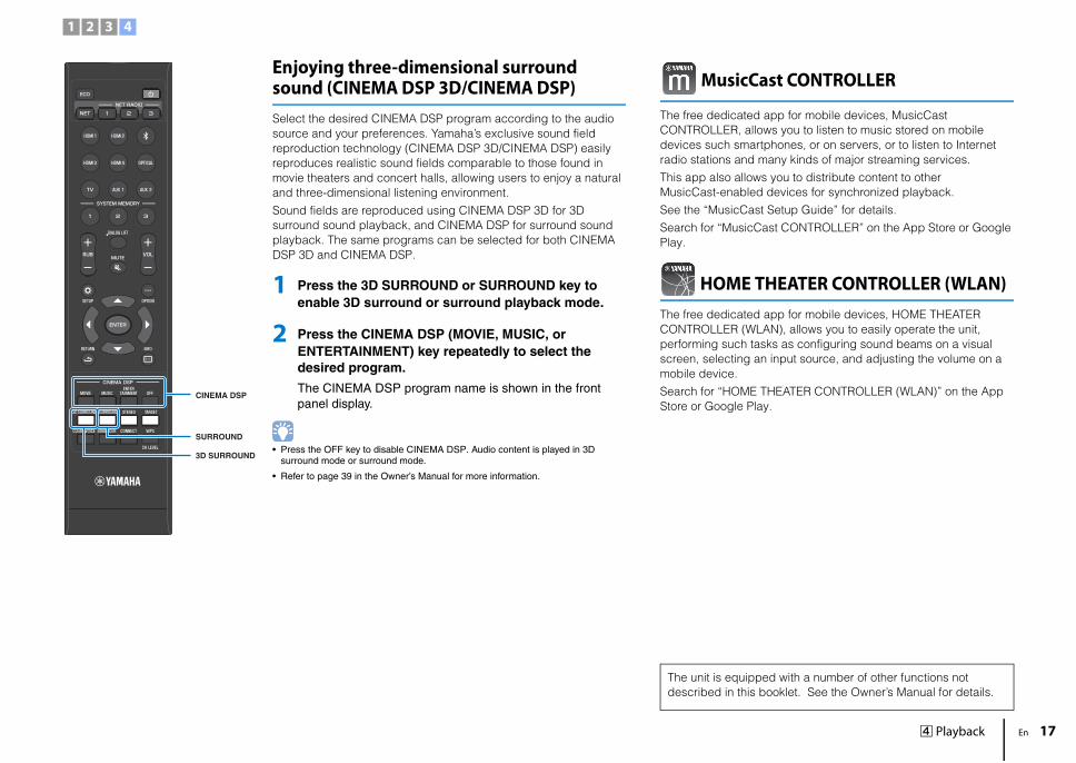
Enjoying three-dimensional surround sound (CINEMA DSP 3D/CINEMA DSP)Select the desired CINEMA DSP program according to the audio source and your preferences. Yamaha’s exclusive sound field reproduction technology (CINEMA DSP 3D/CINEMA DSP) easily reproduces realistic sound fields comparable to those found in movie theaters and concert halls, allowing users to enjoy a natural and three-dimensional listening environment.
Sound fields are reproduced using CINEMA DSP 3D for 3D surround sound playback, and CINEMA DSP for surround sound playback. The same programs can be selected for both CINEMA DSP 3D and CINEMA DSP.
1 Press the 3D SURROUND or SURROUND key to enable 3D surround or surround playback mode.
2 Press the CINEMA DSP (MOVIE, MUSIC, or ENTERTAINMENT) key repeatedly to select the desired program.
The CINEMA DSP program name is shown in the front panel display.
• Press the OFF key to disable CINEMA DSP. Audio content is played in 3D surround mode or surround mode.
• Refer to page 39 in the Owner’s Manual for more information.
MusicCast CONTROLLER
The free dedicated app for mobile devices, MusicCast CONTROLLER, allows you to listen to music stored on mobile devices such smartphones, or on servers, or to listen to Internet radio stations and many kinds of major streaming services.
This app also allows you to distribute content to other MusicCast-enabled devices for synchronized playback.
See the “MusicCast Setup Guide” for details.
Search for “MusicCast CONTROLLER” on the App Store or Google Play.
HOME THEATER CONTROLLER (WLAN)The free dedicated app for mobile devices, HOME THEATER CONTROLLER (WLAN), allows you to easily operate the unit, performing such tasks as configuring sound beams on a visual screen, selecting an input source, and adjusting the volume on a mobile device.
Search for “HOME THEATER CONTROLLER (WLAN)” on the App Store or Google Play.
The unit is equipped with a number of other functions not described in this booklet. See the Owner’s Manual for details.
1 2 3 4
CINEMA DSP
3D SURROUND
SURROUND

© 2015 Yamaha Corporation Printed in Indonesia ZS46210
AVEG1A1102C
Important Notice:Guarantee Information for customers in EEA* and Switzerland
English
For detailed guarantee information about this Yamaha product, and Pan-EEA* and Switzerland warranty service, please either visit the website address below (Printable file is available at our website) or contact the Yamaha representative office for your country. *EEA:European Economic Area
http://europe.yamaha.com/warranty/