Quantitative Identification of Multiple Cracks in a Rotor...
24
Copyright © 2012 Tech Science Press CMES, vol.84, no.3, pp.205-228, 2012 Quantitative Identification of Multiple Cracks in a Rotor Utilizing Wavelet Finite Element Method Bing Li 1, 2 and Hongbo Dong 1 Abstract: Different from single crack identification method, the number of cracks should be firstly identified, and then the location and depth of each crack can be predicted for multiple cracks identification technology. This paper presents a mul- tiple crack identification algorithm for rotor using wavelet finite element method. Firstly, the changes in natural frequency of a structure with various crack locations and depths are accurately obtained by means of wavelet finite element method; and then the damage coefficient method is used to determine the number and region of cracks. Finally, by finding the points of intersection of three frequency contour lines in the small region containing crack, the crack location and depth can be pre- dicted. Multiple cracks diagnostic examples in rotor under two working conditions have shown the effectiveness of current method: with a maximum error of crack location identification 0.6% and of crack depth identification 0.7%. Keywords: Multiple cracks; Rotor; Identification; Wavelet finite element method 1 Introduction Rotating machines are extensively used in diverse engineering applications, such as power station, marine propulsion systems, aircraft engines, etc. The operating speed, power, and load of rotating machinery will increase if weight and dimen- sional tolerance decrease for operation at higher mechanical efficiency. Conse- quently, many practical rotor dynamic systems contained rotor elements are highly susceptible to transverse cracks due to fatigue [Green and Casey (2005)]. A crack not detected in time can result in catastrophic failure and cause injuries and severe damage to machinery. Many investigators have studied the crack identification problems in structures [Morassi (2001); Lele and Maiti (2002); Gasch (1993); Di- marogonas (1996); Salawu (1997)]. Morassi proposed a detect method for shaft 1 State Key Laboratory for Manufacturing System, Xi’an Jiaotong University, Xi’an 710072, China 2 Corresponding author: Tel.: +86-29-82663689; fax: +86-29-82663689; E-mail address: [email protected] (B. Li)
Transcript of Quantitative Identification of Multiple Cracks in a Rotor...
Copyright © 2012 Tech Science Press CMES, vol.84, no.3, pp.205-228, 2012
Quantitative Identification of Multiple Cracks in a RotorUtilizing Wavelet Finite Element Method
Bing Li1,2 and Hongbo Dong1
Abstract: Different from single crack identification method, the number of cracksshould be firstly identified, and then the location and depth of each crack can bepredicted for multiple cracks identification technology. This paper presents a mul-tiple crack identification algorithm for rotor using wavelet finite element method.Firstly, the changes in natural frequency of a structure with various crack locationsand depths are accurately obtained by means of wavelet finite element method; andthen the damage coefficient method is used to determine the number and regionof cracks. Finally, by finding the points of intersection of three frequency contourlines in the small region containing crack, the crack location and depth can be pre-dicted. Multiple cracks diagnostic examples in rotor under two working conditionshave shown the effectiveness of current method: with a maximum error of cracklocation identification 0.6% and of crack depth identification 0.7%.
Keywords: Multiple cracks; Rotor; Identification; Wavelet finite element method
1 Introduction
Rotating machines are extensively used in diverse engineering applications, suchas power station, marine propulsion systems, aircraft engines, etc. The operatingspeed, power, and load of rotating machinery will increase if weight and dimen-sional tolerance decrease for operation at higher mechanical efficiency. Conse-quently, many practical rotor dynamic systems contained rotor elements are highlysusceptible to transverse cracks due to fatigue [Green and Casey (2005)]. A cracknot detected in time can result in catastrophic failure and cause injuries and severedamage to machinery. Many investigators have studied the crack identificationproblems in structures [Morassi (2001); Lele and Maiti (2002); Gasch (1993); Di-marogonas (1996); Salawu (1997)]. Morassi proposed a detect method for shaft
1 State Key Laboratory for Manufacturing System, Xi’an Jiaotong University, Xi’an 710072, China2 Corresponding author: Tel.: +86-29-82663689; fax: +86-29-82663689; E-mail address:
[email protected] (B. Li)
206 Copyright © 2012 Tech Science Press CMES, vol.84, no.3, pp.205-228, 2012
with an open crack, which is based on the changes in a pair of natural frequenciesand closed-form solutions of the structures [Morassi (2001)]. Lele and Maiti inves-tigated crack identification techniques by using eight-node iso-parametric elementsto make an efficient calculation for single crack identification in structures [Leleand Maiti (2002)]. Sekhar proposed a model-based method which replaced thefault-induced change of the shaft by equivalent loads in the finite element method(FEM) [Sekhar (2004)]. Anjan using an adaptive h-version FEM for structure dam-age detection in order to control the discretization error because the traditional finiteelements are impotent to describe the singular behavior of cracks and numerous el-ements are needed for numerical computation [Anjan and Talukdar (2004)]. Gasch[Gasch (1993)], Dimarogonas [Dimarogonas (1996)], Salawu [Salawu (1997)], andSekhar [Sekhar (2011)] reviewed crack identification methods based on the dy-namic behavior changes. And many new methods have also been introduced atthe 7th vibration engineering meeting in 2011 (VETOMAC 2011). However, mostmethods concerning crack identification deal with single crack, the case of multiplecracks has not received the same degree of attention.
In the structural damage, there is often more than one type of crack occurring inmore than one region, actually. If the damage identification is dealt blindly with thesingle crack detection method when the damage situation is still unknown, it willprobably lead to miss report or give false information about the fault. Therefore, itis of great importance to accurately diagnose the specific location and depth of eachcrack. Quantitative identification of multiple cracks is much more complicated thanthat of single crack mainly because of the following two aspects:
The cracks will destroy the continuity of the entire structure and with the occur-rence of each crack, four boundary condition equations will be introduced whichwill undoubtedly increase the difficulty of crack analysis;
In the multiple cracks diagnosis, the number of cracks should be firstly identified,and then the location and depth of each crack can be predicted, obviously it is morecomplex than the single crack diagnosis.
Some investigators have studied the quantitative identification of multiple cracks instructures in recent years [Patil and Maiti (2003); Xiang and Liang (2011); Chen,Li, Zi and He (2005); Bao and Wang (2011); He and Lu (2010); Zhang, Han andLi (2010)]. The first idea of multiple cracks identification came from the damagecoefficient method present by Hu and Liang [Liang, Hu and Choy (1992); Hu andLiang (1993)]. They divided a beam containing an arbitrary number of cracks intoseveral finite segments and each segment might contain cracks. From the energypoint of view, they considered that the natural frequency of the beam had a linearcorrelation with the crack parameters (crack position and depth). And by meansof symbolic computation method, they worked out the specific relation expression:
Quantitative Identification of Multiple Cracks 207
∆ω∆ω∆ω/ωωω = 2HS, where ∆ω∆ω∆ω/ωωω is the column matrix representing the change rate ofthe natural frequency, matrix H is the influence matrix and matrix S is the damagecoefficient matrix. The damage coefficient S will be obtained by solving the aboveequation. And if the coefficient of the unit is greater than zero, this unit would bediagnosed as a cracked unit and the magnitude of the coefficient reflected the crackdepth.
Based on the damage coefficient method, Sekhar considered the difference of dif-ferent crack depths and crack locations on rotor dynamic characteristics, analyzeda rotor containing two open cracks with FEM and calculated its characteristic fre-quency and main vibration mode [Sekhar (2008)]. Ruotolo and Surace investigatedthe bending vibration of bars with a random number of open cracks and proposedthe smooth function method and transfer matrix method to calculate the vibration ofa bar with multiple cracks and the solution agreed well with the experimental results[Ruotolo and Surace (2004)]. Moreover, Hollander [Hollander, Wunsche, Henkeland Theilig (2012)], Lee [Lee (2009)], Lin [Lin and Cheng (2008)], and Lam [Lamand Yin (2010)] also have explored the analytic and finite element methods for themultiple cracks problem.
However the analytic method is difficult to be used to calculate the dynamic behav-iors for cracked structures with complex geometry. In additionally, because of thefact that the crack tip field displacement and stress have 1/
√τ singularity ( τ de-
notes crack tip field radius in polar coordinates) and the traditional FEM piecewisepolynomial cannot approximate them accurately on a local area [Kardestuncer andNorrie (1987)], a fine mesh and great amount of computational work is requiredwhen the traditional finite elements are used to describe the singular behavior ofcracks. To overcome these difficulties, wavelets have been applied to finite elementanalysis because wavelet multiresolution theory provides a powerful mathemati-cal tool for function approximation and multiscale representations. Since B-Splinewavelet on the interval (BSWI) has explicit expressions, which allows us to con-veniently calculate the element stiffness matrix. Furthermore, B-spline waveletshave the best approximation properties among all known wavelets of a given or-der and wavelets on the interval have good characteristic of localization, whichcan overcome some numerical instability phenomena [Goswami, Chan and Chui(1995)]. Therefore, Scaling functions of BSWI at a certain scale are adopted toform the shape functions and construct wavelet-based elements. Xiang [Xiang,Zhong, Chen and He (2008)], Li [Li, Dong, Xiang, Qi and He (2011)], and Dong[Dong, Chen, Li, Qi and He (2009)] constructed wavelet-based crack elements ofBSWI to build FEM models of a cracked rotor and clamped beam with a rectangu-lar cross-section, and then identified the crack location and size by using the firstthree simulative frequencies of single cracked structures.
208 Copyright © 2012 Tech Science Press CMES, vol.84, no.3, pp.205-228, 2012
In this paper, we introduced wavelet finite element method (WFEM) to multiplecracks identification problems, and present a quantitative algorithm for the detec-tion of each crack in rotor. Firstly, the changes in natural frequency of a struc-ture with various crack locations and depths are accurately obtained by means ofwavelet finite element method; and then the damage coefficient method is used todetermine the number and region of cracks. Finally, by finding the points of in-tersection of three frequency contour lines in the small unit containing crack, thecrack location and depth can be identified. To verify the effectiveness of the pre-sented method, we have performed simulations in rotor with multiple cracks. Theresults of the multiple cracks diagnosis tests under two working condition cases areas follows: with a maximum error of crack location detection 0.6% and of crackdepth detection 0.7%.
2 Theoretical basis
2.1 The basic principle of crack identification
The crack will introduce local flexibility to the structure which changes dynamiccharacteristics of the whole structure. In vibration diagnosis, structure frequencychange is regarded as the basis of structure crack identification [Naniwadekar, Naikand Maiti (2008)]. Usually, the frequency-based crack detection method includestwo procedures [Li, Chen and He (2005)]. The forward problem is to determinethe first three natural frequencies of the cracked structure given the location anddepth of the crack. The inverse problem is to determine the location and depth ofthe crack given the first three natural frequencies of the cracked beam.
As for a structure, its natural frequency is changed with the appearance of cracks.Let ωn (n = 1,2,3, . . .) be the nth order natural frequency, the relationship amongcrack location, depth and natural frequency of the beam are as follows£º
ωn = g(a,b) , (n = 1,2,3, . . .) (1)
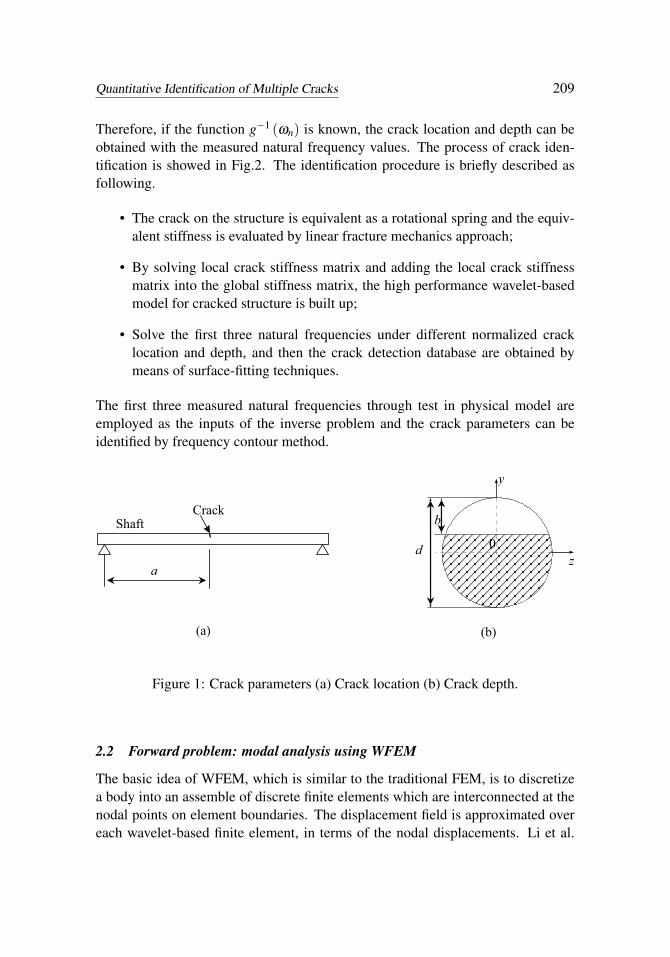
Where a and b are the position and depth of the crack respectively, shown in Fig. 1.The forward problem of crack identification can be viewed as to solve the naturalfrequency of the structure with the known function g(a,b) and crack parameters aand b.
If the measured natural frequency is known, the inverse problem, that is to de-termine the location and depth of the cracks, can be described with the followingfunction:
(a,b) = g−1 (ωn) , (n = 1,2,3, . . .) (2)
Quantitative Identification of Multiple Cracks 209
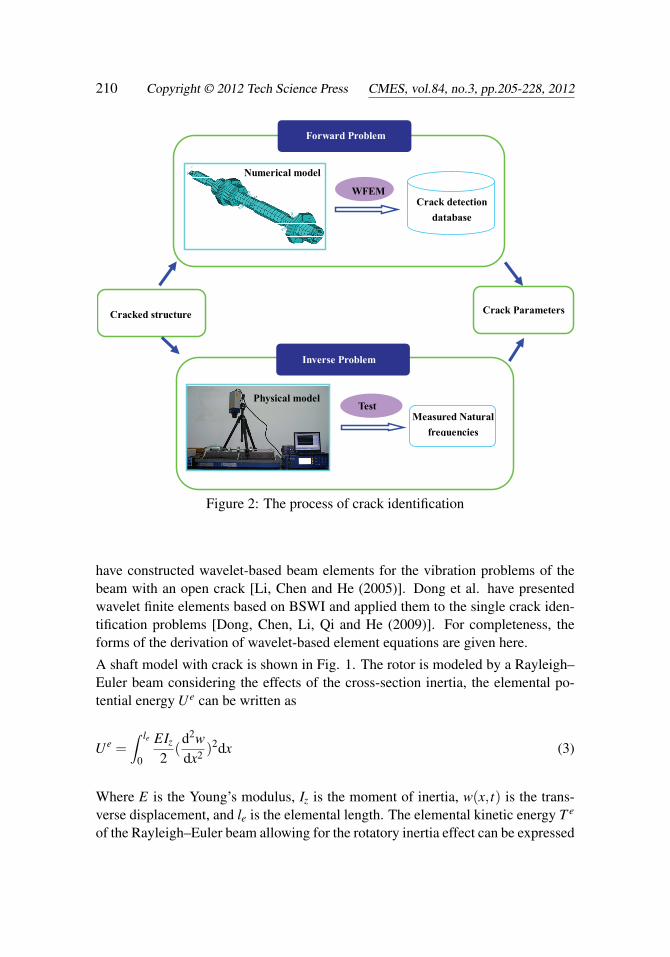
Therefore, if the function g−1 (ωn) is known, the crack location and depth can beobtained with the measured natural frequency values. The process of crack iden-tification is showed in Fig.2. The identification procedure is briefly described asfollowing.
• The crack on the structure is equivalent as a rotational spring and the equiv-alent stiffness is evaluated by linear fracture mechanics approach;
• By solving local crack stiffness matrix and adding the local crack stiffnessmatrix into the global stiffness matrix, the high performance wavelet-basedmodel for cracked structure is built up;
• Solve the first three natural frequencies under different normalized cracklocation and depth, and then the crack detection database are obtained bymeans of surface-fitting techniques.
The first three measured natural frequencies through test in physical model areemployed as the inputs of the inverse problem and the crack parameters can beidentified by frequency contour method.
(a) (b)
Shaft Crack
a d 0
y
z
b
Figure 1: Crack parameters (a) Crack location (b) Crack depth.
2.2 Forward problem: modal analysis using WFEM
The basic idea of WFEM, which is similar to the traditional FEM, is to discretizea body into an assemble of discrete finite elements which are interconnected at thenodal points on element boundaries. The displacement field is approximated overeach wavelet-based finite element, in terms of the nodal displacements. Li et al.
210 Copyright © 2012 Tech Science Press CMES, vol.84, no.3, pp.205-228, 2012
Forward Problem
WFEM
Numerical model
Test Measured Natural
frequencies
Crack detection
database
Inverse Problem
Cracked structure
Physical model
Crack Parameters
Figure 2: The process of crack identification
have constructed wavelet-based beam elements for the vibration problems of thebeam with an open crack [Li, Chen and He (2005)]. Dong et al. have presentedwavelet finite elements based on BSWI and applied them to the single crack iden-tification problems [Dong, Chen, Li, Qi and He (2009)]. For completeness, theforms of the derivation of wavelet-based element equations are given here.
A shaft model with crack is shown in Fig. 1. The rotor is modeled by a Rayleigh–Euler beam considering the effects of the cross-section inertia, the elemental po-tential energy Ue can be written as
Ue =∫ le
0
EIz
2(d2wdx2 )2dx (3)
Where E is the Young’s modulus, Iz is the moment of inertia, w(x, t) is the trans-verse displacement, and le is the elemental length. The elemental kinetic energy T e
of the Rayleigh–Euler beam allowing for the rotatory inertia effect can be expressed
Quantitative Identification of Multiple Cracks 211
as
T e =∫ le
0
ρA2
(∂w∂ t
)2dx+∫ le
0
ρIz
2(∂θ
∂ t)2dx (4)
Where ρ is the density, A is the area of the cross-section, θ(x, t) is the rotation ofthe shaft section due to bending and can be given by θ = dw(x,t)
dx = 1le
dw(ξ ,t)dξ
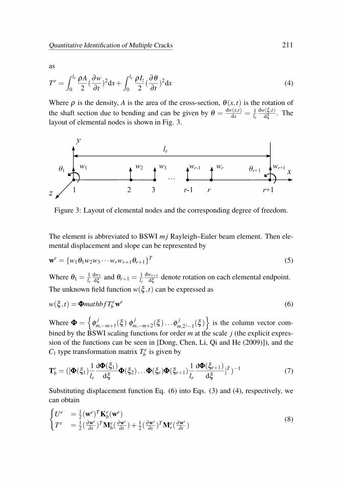
. Thelayout of elemental nodes is shown in Fig. 3.
le
r+11 2 3
x
r-1 r
…w1 θ1 w2 θr+1
wr+1w3 wr wr-1
y
z
Figure 3: Layout of elemental nodes and the corresponding degree of freedom.
The element is abbreviated to BSWI m j Rayleigh–Euler beam element. Then ele-mental displacement and slope can be represented by
we = {w1θ1w2w3 · · ·wrwr+1θr+1}T (5)
Where θ1 = 1le
dw1dξ
and θr+1 = 1le
dwr+1dξ
denote rotation on each elemental endpoint.
The unknown field function w(ξ , t) can be expressed as
w(ξ , t) = ΦΦΦmathb f T eb we (6)
Where ΦΦΦ ={
φj
m,−m+1(ξ ) φj
m,−m+2(ξ ) . . .φ jm,2 j−1(ξ )
}is the column vector com-
bined by the BSWI scaling functions for order m at the scale j (the explicit expres-sion of the functions can be seen in [Dong, Chen, Li, Qi and He (2009)]), and theC1 type transformation matrix T e
b is given by
Teb = ([ΦΦΦ(ξ1)
1le
dΦΦΦ(ξ1)dξ
ΦΦΦ(ξ2) . . .ΦΦΦ(ξr)ΦΦΦ(ξr+1)1le
dΦΦΦ(ξr+1)dξ
]T )−1 (7)
Substituting displacement function Eq. (6) into Eqs. (3) and (4), respectively, wecan obtain{
Ue = 12(we)T Ke
b(we)
T e = 12( ∂we
∂ t )T Meb(
∂we
∂ t )+ 12( ∂we
∂ t )T Mer(
∂we
∂ t )(8)
212 Copyright © 2012 Tech Science Press CMES, vol.84, no.3, pp.205-228, 2012
Where Keb, Me
b, Mer are the bending stiffness matrixes, translational mass matrix and
rotatory inertia mass matrix of the structure respectively, their explicit expressionof the functions can be seen in [Dong, Chen, Li, Qi and He (2009)].
The elemental Lagrangian function La is
La = Ue−T e =12(we)T Ke
b(we)− 1
2(∂we
∂ t)T Me
b(∂we
∂ t)− 1
2(∂we
∂ t)T Me
r(∂we
∂ t) (9)
Applying Hamilton’s principle to the elemental Lagrangian function La, we canobtain the elemental free vibration equation
(Meb +Me
r)(∂ 2we
∂ t2 )+Kebwe = 0 (10)
and the corresponding elemental free vibration frequency equations is∣∣Keb−ω
2n (Me
b +Mer)∣∣= 0 (11)
Where ωn is the natural frequency.
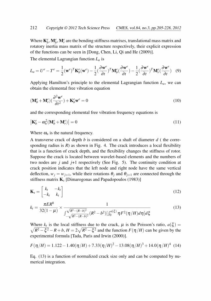
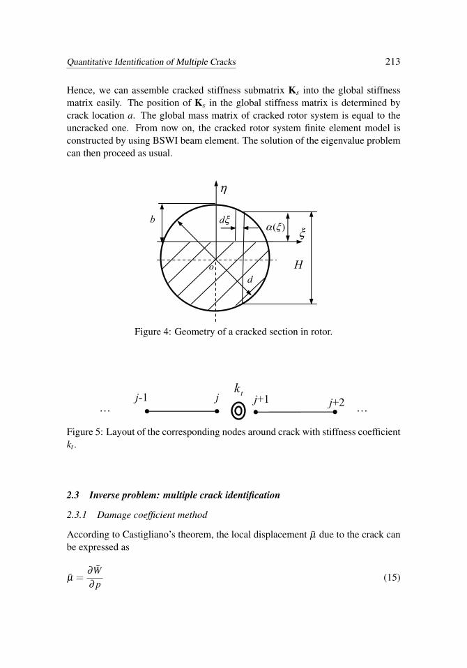
A transverse crack of depth b is considered on a shaft of diameter d ( the corre-sponding radius is R) as shown in Fig. 4. The crack introduces a local flexibilitythat is a function of crack depth, and the flexibility changes the stiffness of rotor.Suppose the crack is located between wavelet-based elements and the numbers oftwo nodes are j and j+1 respectively (See Fig. 5). The continuity condition atcrack position indicates that the left node and right node have the same verticaldeflection, w j = w j+1, while their rotations θ j and θ j+1 are connected through thestiffness matrix Ks [Dimarogonas and Papadopoulos (1983)]
Ks =[
kt −kt
−kt kt
](12)
kt =πER8
32(1−µ)× 1∫√R2−(R−b)2
−√
R2−(R−b)2(R2−b2)[
∫ a(ξ )0 ηF2(η/H)dη ]dξ
(13)
Where kt is the local stiffness due to the crack, µ is the Poisson’s ratio, a(ξ ) =√R2−ξ 2−R+b, H = 2
√R2−ξ 2 and the function F(η/H) can be given by the
experimental formula [Tada, Paris and Irwin (2000)].
F(η/H) = 1.122−1.40(η/H)+7.33(η/H)2−13.08(η/H)3 +14.0(η/H)4 (14)
Eq. (13) is a function of normalized crack size only and can be computed by nu-merical integration.
Quantitative Identification of Multiple Cracks 213
Hence, we can assemble cracked stiffness submatrix Ks into the global stiffnessmatrix easily. The position of Ks in the global stiffness matrix is determined bycrack location a. The global mass matrix of cracked rotor system is equal to theuncracked one. From now on, the cracked rotor system finite element model isconstructed by using BSWI beam element. The solution of the eigenvalue problemcan then proceed as usual.
ξ
η
b
d o H
)(ξα ξd
Figure 4: Geometry of a cracked section in rotor.
j-1 j …
j+1 …j+2
tk
Figure 5: Layout of the corresponding nodes around crack with stiffness coefficientkt .
2.3 Inverse problem: multiple crack identification
2.3.1 Damage coefficient method
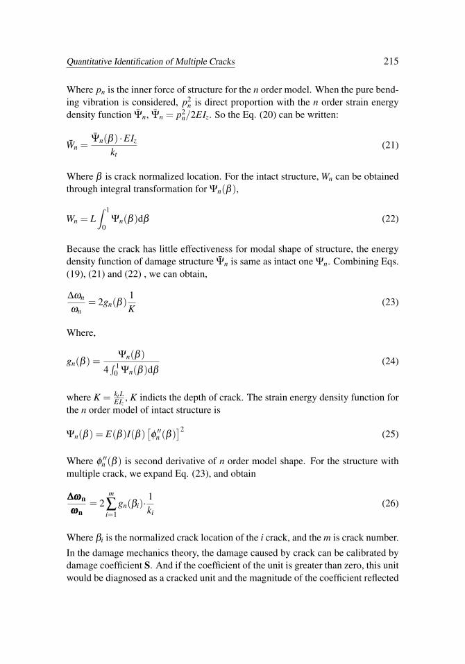
According to Castigliano’s theorem, the local displacement µ̄ due to the crack canbe expressed as
µ̄ =∂W̄∂ p
(15)

214 Copyright © 2012 Tech Science Press CMES, vol.84, no.3, pp.205-228, 2012
Where W̄ is local strain energy due to crack, p is the force or moment of structure,as shown in Fig. 6. For crack element, W̄ =
∫ b0 J(α)dα , α is crack normalized
depth, α = b/d, and J(α) is energy density function.
u
p p b
Figure 6: Crack element
The local flexibility c due to the crack can be defined as
c =∂ µ̄
∂ p(16)
and the local stiffness kt due to the crack is kt=1/c, we put Eq. (15) into Eq. (16),and obtain
1kt
=∂ 2W̄∂ p2 (17)
It is an effective method to treat the crack as a rotating spring model. When thestructure is intact, the spring stiffness kt is infinite. kt increases as the crack depthenlarges. Gudmundson given the relation of natural frequencies between the dam-age structures and intact ones [Gudmudson (1982)]:
ω̄2n
ω2n
= 1− W̄n
Wn(18)
Where, ω̄n and ωn are the natural frequencies for damage structure and intact onerespectively. W̄n is n the order strain energy due to crack, Wn is strain energy for then order model of intact structure.
According to Eq. (18), we have ω2n−ω̄2
nω2
n= W̄n
Wn⇒ (ωn+ω̄n)(ωn−ω̄n)
ω2n
= W̄nWn
. Because(ωn + ω̄n)≈ 2ωn, so the Eq. (18) can be written as
∆ωn
ωn=
12· W̄n
Wn(19)
Where ∆ωn = ωn− ω̄n. By integral transformation, the Eq. (17) is
W̄n =p2
n
2kt(20)
Quantitative Identification of Multiple Cracks 215
Where pn is the inner force of structure for the n order model. When the pure bend-ing vibration is considered, p2
n is direct proportion with the n order strain energydensity function Ψ̄n, Ψ̄n = p2
n/2EIz. So the Eq. (20) can be written:
W̄n =Ψ̄n(β ) ·EIz
kt(21)
Where β is crack normalized location. For the intact structure, Wn can be obtainedthrough integral transformation for Ψn(β ),
Wn = L∫ 1
0Ψn(β )dβ (22)
Because the crack has little effectiveness for modal shape of structure, the energydensity function of damage structure Ψ̄n is same as intact one Ψn. Combining Eqs.(19), (21) and (22) , we can obtain,
∆ωn
ωn= 2gn(β )
1K
(23)
Where,
gn(β ) =Ψn(β )
4∫ 1
0 Ψn(β )dβ(24)
where K = kt LEIz
, K indicts the depth of crack. The strain energy density function forthe n order model of intact structure is
Ψn(β ) = E(β )I(β )[φ′′n (β )
]2 (25)
Where φ ′′n (β ) is second derivative of n order model shape. For the structure withmultiple crack, we expand Eq. (23), and obtain
∆ω∆ω∆ωn
ωωωn= 2
m
∑i=1
gn(βi)·1ki
(26)
Where βi is the normalized crack location of the i crack, and the m is crack number.
In the damage mechanics theory, the damage caused by crack can be calibrated bydamage coefficient S. And if the coefficient of the unit is greater than zero, this unitwould be diagnosed as a cracked unit and the magnitude of the coefficient reflected
216 Copyright © 2012 Tech Science Press CMES, vol.84, no.3, pp.205-228, 2012
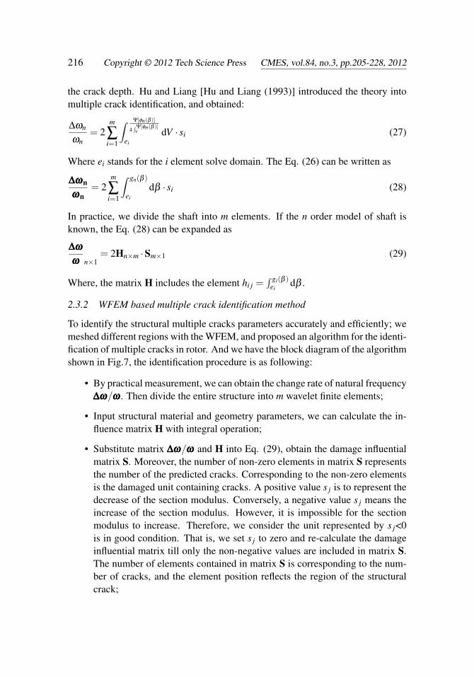
the crack depth. Hu and Liang [Hu and Liang (1993)] introduced the theory intomultiple crack identification, and obtained:
∆ωn
ωn= 2
m
∑i=1
∫ Ψ[φn(β )]
4∫Ψ[φn(β )]v
ei
dV · si (27)
Where ei stands for the i element solve domain. The Eq. (26) can be written as
∆ω∆ω∆ωn
ωωωn= 2
m
∑i=1
∫ gn(β )
ei
dβ · si (28)
In practice, we divide the shaft into m elements. If the n order model of shaft isknown, the Eq. (28) can be expanded as
∆ω∆ω∆ω
ωωω n×1= 2Hn×m ·Sm×1 (29)
Where, the matrix H includes the element hi j =∫ gi(β )
eidβ .
2.3.2 WFEM based multiple crack identification method
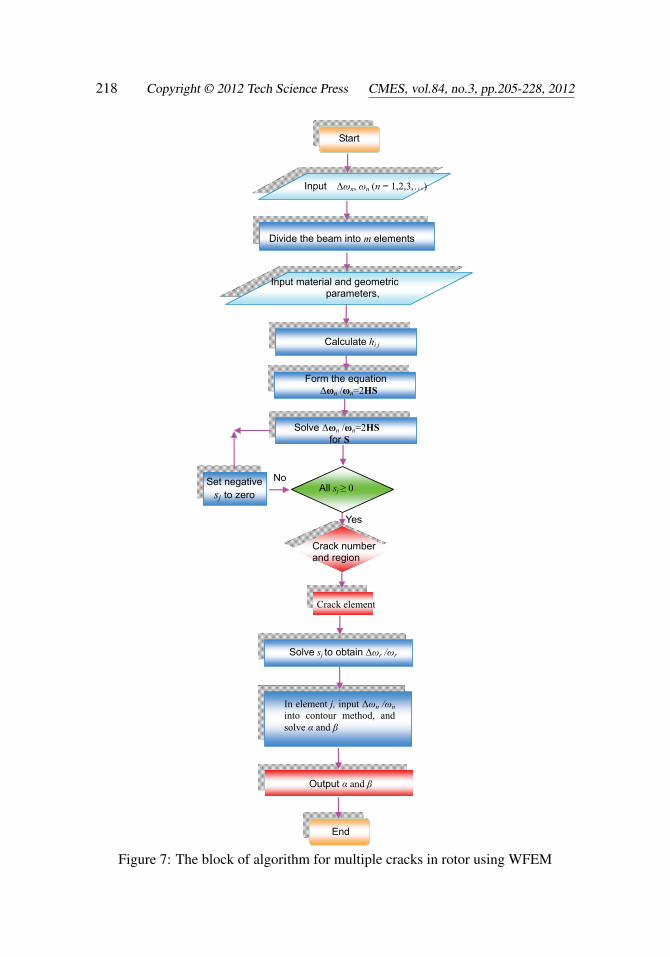
To identify the structural multiple cracks parameters accurately and efficiently; wemeshed different regions with the WFEM, and proposed an algorithm for the identi-fication of multiple cracks in rotor. And we have the block diagram of the algorithmshown in Fig.7, the identification procedure is as following:
• By practical measurement, we can obtain the change rate of natural frequency∆ω∆ω∆ω/ωωω . Then divide the entire structure into m wavelet finite elements;
• Input structural material and geometry parameters, we can calculate the in-fluence matrix H with integral operation;
• Substitute matrix ∆ω∆ω∆ω/ωωω and H into Eq. (29), obtain the damage influentialmatrix S. Moreover, the number of non-zero elements in matrix S representsthe number of the predicted cracks. Corresponding to the non-zero elementsis the damaged unit containing cracks. A positive value s j is to represent thedecrease of the section modulus. Conversely, a negative value s j means theincrease of the section modulus. However, it is impossible for the sectionmodulus to increase. Therefore, we consider the unit represented by s j<0is in good condition. That is, we set s j to zero and re-calculate the damageinfluential matrix till only the non-negative values are included in matrix S.The number of elements contained in matrix S is corresponding to the num-ber of cracks, and the element position reflects the region of the structuralcrack;
Quantitative Identification of Multiple Cracks 217
• To detect the depth of the crack, we need to calculate the change rate of thefirst three orders of natural frequency corresponding by the damage coeffi-cient in each cracked element;
• We take the change rate as input parameter of the three-line intersection ina single crack detection method [Li, Chen and He (2005)] and plot the fre-quency contour line of each mode. The intersection of the three contour linespredicts the specific position and depth of the crack.
3 Example verification
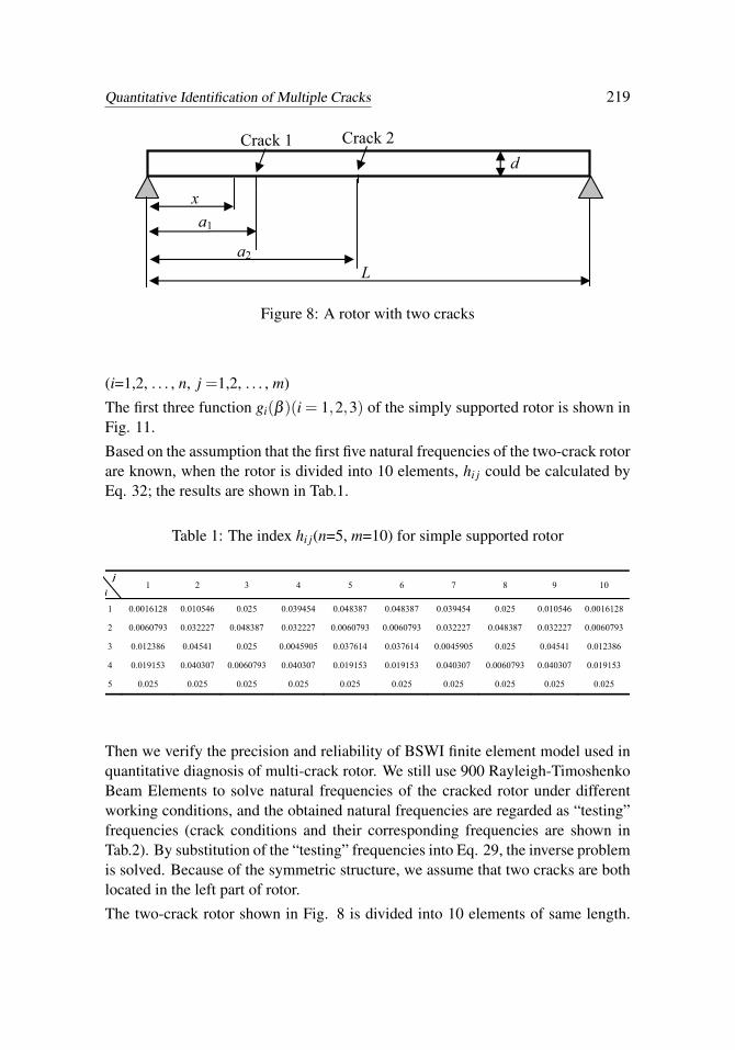
The validity of the proposed method is testified by a simulation of rotor systemwith two cracks, as shown in Fig. 8. Dimensions of the rotor are total lengthL = 300mm, diameter d = 10mm. The corresponding material properties are: E =2.06e11N / m2, ρ = 7860kg / m3 and µ = 0.3. The positional dimensions of thetwo cracks are: a1 and a2, relative position β1 and β2are defined as: β1 = a1/L andβ2 = a2/L.
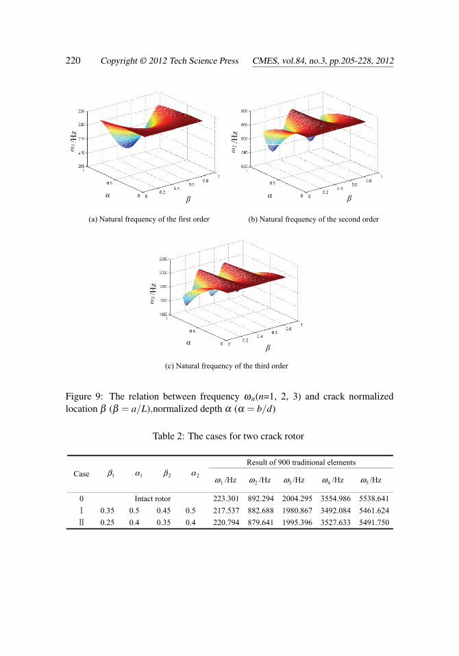
30 BSWI Rayleigh-Timoshenko beam elements are used to discrete the rotor. Themodel database of crack diagnosis forward problem is established according to thedifferent location and depth of crack, as shown in Fig. 9. Fig. 10 shows howfirst three natural frequency rate changes with different depths of the two cracks atdifferent locations.
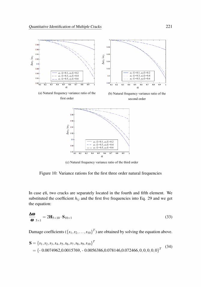
As can be seen from Fig. 10 (a), when β1 and β2 get close to 1/2, crack depth hasthe most obvious influence on the first natural frequency of rotor. From Fig. 10 (b),crack depth has the most significant influence on the second natural frequency ofrotor when β1 and β2 get close to 1/4. Similar to the above, in Fig. 10 (c), whenβ1 and β2 get close to 1/6, crack depth has the most obvious influence on the thirdnatural frequency of rotor.
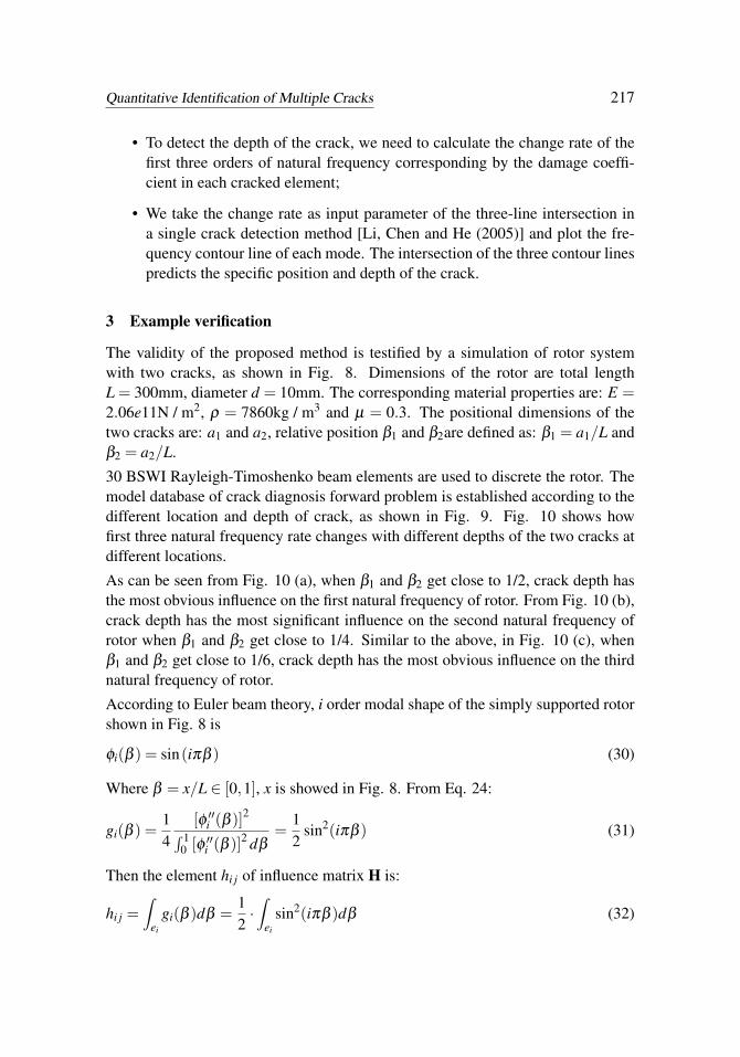
According to Euler beam theory, i order modal shape of the simply supported rotorshown in Fig. 8 is
φi(β ) = sin(iπβ ) (30)
Where β = x/L ∈ [0,1], x is showed in Fig. 8. From Eq. 24:
gi(β ) =14
[φ ′′i (β )]2∫ 10 [φ ′′i (β )]2 dβ
=12
sin2(iπβ ) (31)
Then the element hi j of influence matrix H is:
hi j =∫
ei
gi(β )dβ =12·∫
ei
sin2(iπβ )dβ (32)
218 Copyright © 2012 Tech Science Press CMES, vol.84, no.3, pp.205-228, 2012
Start
Input Δωn, ωn (n = 1,2,3,…)
Divide the beam into m elements
Input material and geometric parameters,
Calculate hi j
Form the equation Δωn /ωn=2HS
Solve Δωn /ωn=2HS for S
All sj ≥ 0
End
No
Yes
Crack number and region
Solve sj to obtain Δωr /ωr
In element j, input Δωn /ωn into contour method, and solve α and β
Output α and β
Set negative sj to zero
Crack element
Figure 7: The block of algorithm for multiple cracks in rotor using WFEM
Quantitative Identification of Multiple Cracks 219
L
a1
a2
dCrack 2
x
Crack 1
Figure 8: A rotor with two cracks
(i=1,2, . . . , n, j =1,2, . . . , m)
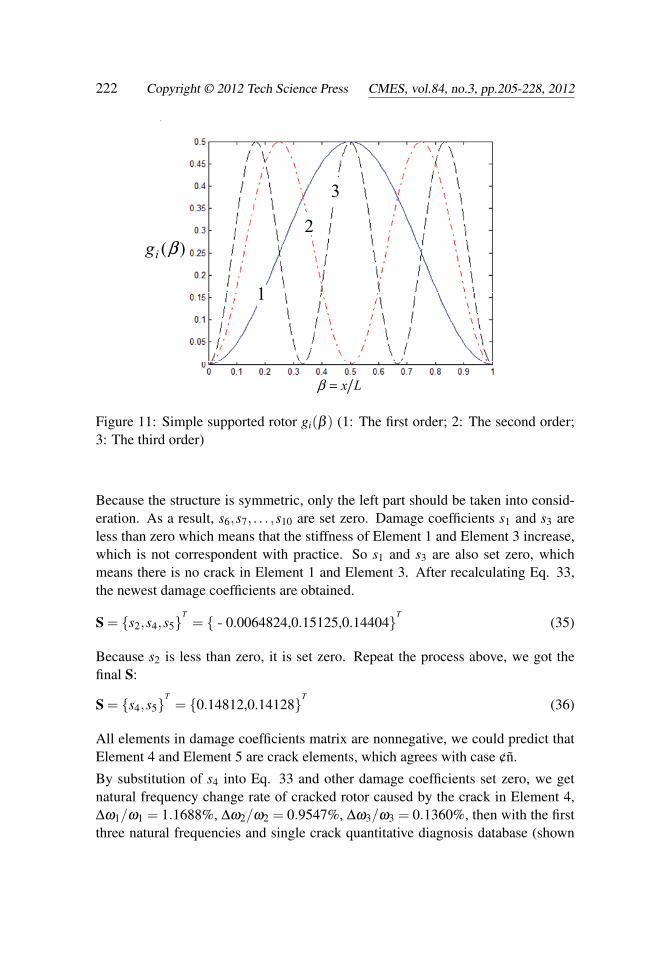
The first three function gi(β )(i = 1,2,3) of the simply supported rotor is shown inFig. 11.
Based on the assumption that the first five natural frequencies of the two-crack rotorare known, when the rotor is divided into 10 elements, hi j could be calculated byEq. 32; the results are shown in Tab.1.
Table 1: The index hi j(n=5, m=10) for simple supported rotor
j
i 1 2 3 4 5 6 7 8 9 10
1 0.0016128 0.010546 0.025 0.039454 0.048387 0.048387 0.039454 0.025 0.010546 0.0016128
2 0.0060793 0.032227 0.048387 0.032227 0.0060793 0.0060793 0.032227 0.048387 0.032227 0.0060793
3 0.012386 0.04541 0.025 0.0045905 0.037614 0.037614 0.0045905 0.025 0.04541 0.012386
4 0.019153 0.040307 0.0060793 0.040307 0.019153 0.019153 0.040307 0.0060793 0.040307 0.019153
5 0.025 0.025 0.025 0.025 0.025 0.025 0.025 0.025 0.025 0.025
Then we verify the precision and reliability of BSWI finite element model used inquantitative diagnosis of multi-crack rotor. We still use 900 Rayleigh-TimoshenkoBeam Elements to solve natural frequencies of the cracked rotor under differentworking conditions, and the obtained natural frequencies are regarded as “testing”frequencies (crack conditions and their corresponding frequencies are shown inTab.2). By substitution of the “testing” frequencies into Eq. 29, the inverse problemis solved. Because of the symmetric structure, we assume that two cracks are bothlocated in the left part of rotor.
The two-crack rotor shown in Fig. 8 is divided into 10 elements of same length.
220 Copyright © 2012 Tech Science Press CMES, vol.84, no.3, pp.205-228, 2012
(a) 一阶固有频率解曲面 (b) 二阶固有频率解曲面
α β β α
f 1/H
z
f 2/H
z
(c) 三阶固有频率解曲面
β α
f 3/H
z
图 3-25 光轴转子裂纹定量诊断正问题模型数据库
(a) Natural frequency of the first order (b) Natural frequency of the second order
(c) Natural frequency of the third order
ω1
ω2
ω3
Figure 9: The relation between frequency ωn(n=1, 2, 3) and crack normalizedlocation β (β = a/L),normalized depth α (α = b/d)
Table 2: The cases for two crack rotor
Result of 900 traditional elements Case 1β 1α 2β 2α
1ω /Hz 2ω /Hz 3ω /Hz 4ω /Hz 5ω /Hz
0 Intact rotor 223.301 892.294 2004.295 3554.986 5538.641Ⅰ 0.35 0.5 0.45 0.5 217.537 882.688 1980.867 3492.084 5461.624Ⅱ 0.25 0.4 0.35 0.4 220.794 879.641 1995.396 3527.633 5491.750
Quantitative Identification of Multiple Cracks 221
(c) 三阶固有频率变化率
0.1 0.2 0.3 0.4 0.5 0.6 0.7 0.8 0.9 1
α
图 3-26 两裂纹相对深度对固有频率的影响
△f 3/
f 3
(b) 二阶固有频率变化率
0.1 0.2 0.3 0.4 0.5 0.6 0.7 0.8 0.9 1α
△f 2/
f 2
(a) 一阶固有频率变化率
0.1 0.2 0.3 0.4 0.5 0.6 0.7 0.8 0.9 1
△f 1/
f 1
α
(a) Natural frequency variance ratio of the first order
(b) Natural frequency variance ratio of the second order
(c) Natural frequency variance ratio of the third order
Δω1 /ω
1
Δω2 /ω
2
Δω3 /ω
3 a1 /L=0.1, a2/L=0.2 a1 /L=0.3, a2/L=0.4 a1 /L=0.5, a2/L=0.6
a1 /L=0.1, a2/L=0.2a1 /L=0.3, a2/L=0.4a1 /L=0.5, a2/L=0.6
a1 /L=0.1, a2/L=0.2a1 /L=0.3, a2/L=0.4a1 /L=0.5, a2/L=0.6
Figure 10: Variance rations for the first three order natural frequencies
In case ¢ñ, two cracks are separately located in the fourth and fifth element. Wesubstituted the coefficient hi j and the first five frequencies into Eq. 29 and we getthe equation:
∆ω∆ω∆ω
ωωω 5×1= 2H5×10 ·S10×1 (33)
Damage coefficients ({s1,s2, . . . ,s10}T ) are obtained by solving the equation above.
S = {s1,s2,s3,s4,s5,s6,s7,s8,s9,s10}T
= {- 0.0074962,0.0015769, - 0.0056386,0.078146,0.072466,0,0,0,0,0}T (34)
222 Copyright © 2012 Tech Science Press CMES, vol.84, no.3, pp.205-228, 2012
)(βig
Lx=β
图 3-27 简支转子 )(βig (1:一阶; 2:二阶; 3:三阶)
1
2
3
Figure 11: Simple supported rotor gi(β ) (1: The first order; 2: The second order;3: The third order)
Because the structure is symmetric, only the left part should be taken into consid-eration. As a result, s6,s7, . . . ,s10 are set zero. Damage coefficients s1 and s3 areless than zero which means that the stiffness of Element 1 and Element 3 increase,which is not correspondent with practice. So s1 and s3 are also set zero, whichmeans there is no crack in Element 1 and Element 3. After recalculating Eq. 33,the newest damage coefficients are obtained.
S = {s2,s4,s5}T
= { - 0.0064824,0.15125,0.14404}T
(35)
Because s2 is less than zero, it is set zero. Repeat the process above, we got thefinal S:
S = {s4,s5}T
= {0.14812,0.14128}T
(36)
All elements in damage coefficients matrix are nonnegative, we could predict thatElement 4 and Element 5 are crack elements, which agrees with case ¢ñ.
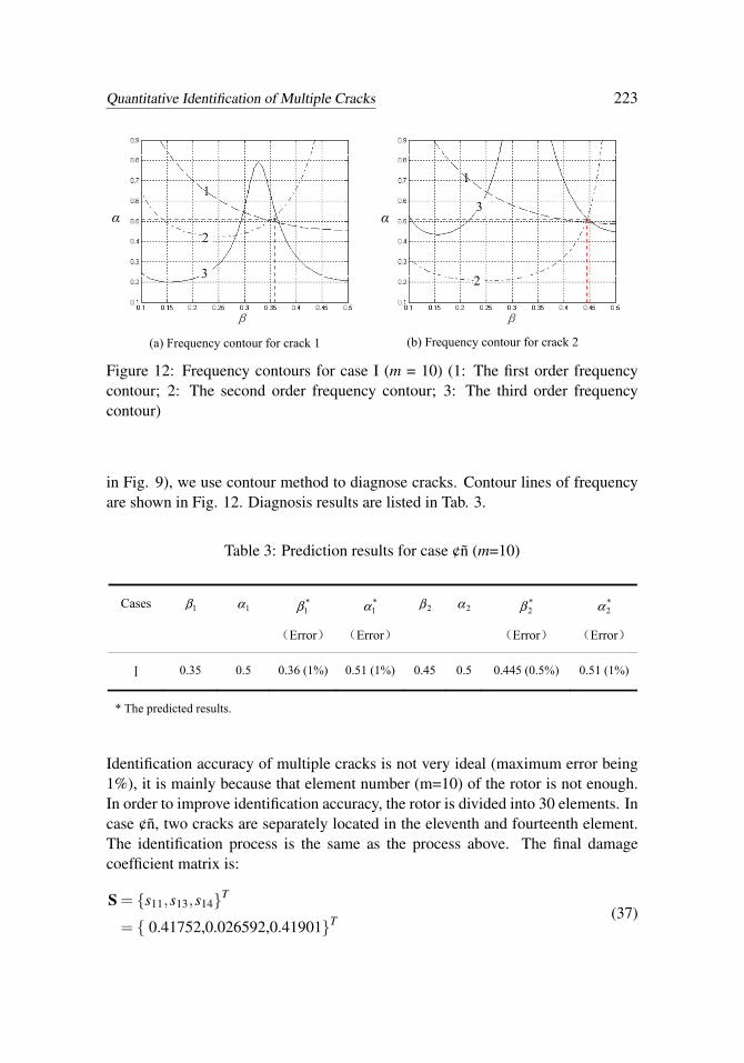
By substitution of s4 into Eq. 33 and other damage coefficients set zero, we getnatural frequency change rate of cracked rotor caused by the crack in Element 4,∆ω1/ω1 = 1.1688%, ∆ω2/ω2 = 0.9547%, ∆ω3/ω3 = 0.1360%, then with the firstthree natural frequencies and single crack quantitative diagnosis database (shown
Quantitative Identification of Multiple Cracks 223
(a) 裂纹 1 频率等高线
图 3-28 工况 1 多裂纹定量诊断频率等高线图 (m=10) (1:一阶频率等高线;2:二阶频率等高线;3:三阶频率等高线)
(b) 裂纹 2 频率等高线
β
α
1
3
2
β
α
1
3
2
(a) Frequency contour for crack 1
(b) Frequency contour for crack 2
Figure 12: Frequency contours for case I (m = 10) (1: The first order frequencycontour; 2: The second order frequency contour; 3: The third order frequencycontour)
in Fig. 9), we use contour method to diagnose cracks. Contour lines of frequencyare shown in Fig. 12. Diagnosis results are listed in Tab. 3.
Table 3: Prediction results for case ¢ñ (m=10)
Cases 1β 1α *1β
(Error)
*1α
(Error)
2β 2α *2β
(Error)
*2α
(Error)
Ⅰ 0.35 0.5 0.36 (1%) 0.51 (1%) 0.45 0.5 0.445 (0.5%) 0.51 (1%)
* The predicted results.
Identification accuracy of multiple cracks is not very ideal (maximum error being1%), it is mainly because that element number (m=10) of the rotor is not enough.In order to improve identification accuracy, the rotor is divided into 30 elements. Incase ¢ñ, two cracks are separately located in the eleventh and fourteenth element.The identification process is the same as the process above. The final damagecoefficient matrix is:
S = {s11,s13,s14}T
= { 0.41752,0.026592,0.41901}T (37)
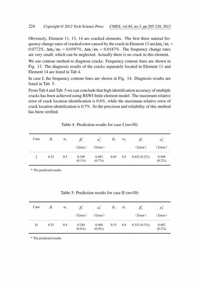
224 Copyright © 2012 Tech Science Press CMES, vol.84, no.3, pp.205-228, 2012
Obviously, Element 11, 13, 14 are cracked elements. The first three natural fre-quency change rates of cracked rotor caused by the crack in Element 13 are∆ω1/ω1 =0.0772%, ∆ω2/ω2 = 0.0397%, ∆ω3/ω3 = 0.0187%. The frequency change ratesare very small, which can be neglected. Actually there is no crack in this element.
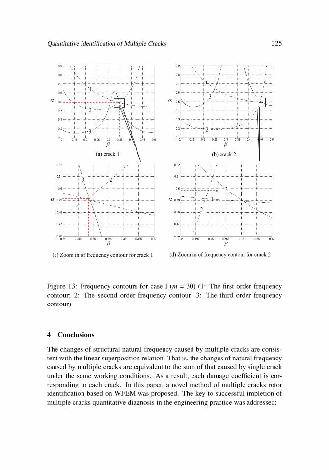
We use contour method to diagnose cracks. Frequency contour lines are shown inFig. 13. The diagnosis results of the cracks separately located in Element 11 andElement 14 are listed in Tab 4.
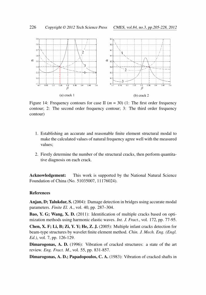
In case I, the frequency contour lines are shown in Fig. 14. Diagnosis results arelisted in Tab. 5.
From Tab.4 and Tab. 5 we can conclude that high identification accuracy of multiplecracks has been achieved using BSWI finite element model. The maximum relativeerror of crack location identification is 0.6%, while the maximum relative error ofcrack location identification is 0.7%. So the precision and reliability of this methodhas been verified.
Table 4: Prediction results for case I (m=30)
Case 1β 1α *1β
(Error)
*1α
(Error)
2β 2α *2β
(Error)
*2α
(Error)
Ⅰ 0.35 0.5 0.349 (0.1%)
0.493 (0.7%)
0.45 0.5 0.452 (0.2%) 0.498 (0.2%)
* The predicted results.
Table 5: Prediction results for case II (m=30)
Case 1β 1α *1β
(Error)
*1α
(Error)
2β 2α *2β
(Error)
*2α
(Error)
Π 0.25 0.4 0.244 (0.6%)
0.404 (0.4%)
0.35 0.4 0.353 (0.3%) 0.402 (0.2%)
* The predicted results.
Quantitative Identification of Multiple Cracks 225
(a) 裂纹 1 频率等高线 β
)/( Leβ
α 1
3
2
图 3-29 工况 1 多裂纹定量诊断频率等高线图(m=30) (1:一阶频率等高线;2:二阶频率等高线;3:三阶频率等高线)
(b) 裂纹 2 频率等高线 β
)/( Leβ
α
1
3
2
(c) 裂纹 1 频率等高线局部放大图 (d) 裂纹 2 频率等高线局部放大图
β
)/( Leβ
α 1
3 2
β
)/( Leβ
α 1
3
2
(a) 裂纹 1 频率等高线 (b) 裂纹 2 频率等高线
(c) 裂纹 1 频率等高线局部放大图 (d) 裂纹 2 频率等高线局部放大图
(a) crack 1 (b) crack 2
(c) Zoom in of frequency contour for crack 1 (d) Zoom in of frequency contour for crack 2
Figure 13: Frequency contours for case I (m = 30) (1: The first order frequencycontour; 2: The second order frequency contour; 3: The third order frequencycontour)
4 Conclusions
The changes of structural natural frequency caused by multiple cracks are consis-tent with the linear superposition relation. That is, the changes of natural frequencycaused by multiple cracks are equivalent to the sum of that caused by single crackunder the same working conditions. As a result, each damage coefficient is cor-responding to each crack. In this paper, a novel method of multiple cracks rotoridentification based on WFEM was proposed. The key to successful impletion ofmultiple cracks quantitative diagnosis in the engineering practice was addressed:
226 Copyright © 2012 Tech Science Press CMES, vol.84, no.3, pp.205-228, 2012
β
α
1
3
2
β
α
1
3
2
(a) 裂纹 1 频率等高线
图 3-30 工况 2 多裂纹定量诊断频率等高线图 (m=30) (1:一阶频率等高线;2:二阶频率等高线;3:三阶频率等高线)
(b) 裂纹 2 频率等高线
(a) crack 1 (b) crack 2
Figure 14: Frequency contours for case II (m = 30) (1: The first order frequencycontour; 2: The second order frequency contour; 3: The third order frequencycontour)
1. Establishing an accurate and reasonable finite element structural modal tomake the calculated values of natural frequency agree well with the measuredvalues;
2. Firstly determine the number of the structural cracks, then perform quantita-tive diagnosis on each crack.
Acknowledgement: This work is supported by the National Natural ScienceFoundation of China (No. 51035007, 11176024).
References
Anjan, D; Talukdar, S. (2004): Damage detection in bridges using accurate modalparameters. Finite El. A., vol. 40, pp. 287–304.
Bao, Y. G; Wang, X. D. (2011): Identification of multiple cracks based on opti-mization methods using harmonic elastic waves. Int. J. Fract., vol. 172, pp. 77-95.
Chen, X. F; Li, B; Zi, Y. Y; He, Z. J. (2005): Multiple infant cracks detection forbeam-type structures by wavelet finite element method. Chin. J. Mech. Eng. (Engl.Ed.), vol. 7, pp. 126-129.
Dimarogonas, A. D. (1996): Vibration of cracked structures: a state of the artreview. Eng. Fract. M., vol. 55, pp. 831-857.
Dimarogonas, A. D.; Papadopoulos, C. A. (1983): Vibration of cracked shafts in
Quantitative Identification of Multiple Cracks 227
bending. J. Sound. Vib., vol. 91, pp. 583–893.
Dong, H. B; Chen, X. F.; Li, B; Qi, K. Y.; He, Z. J. (2009): Rotor crack detectionbased on high-precision modal parameter identification method and wavelet finiteelement model. Mech. Syst. S., vol. 23, pp. 869-883.
Gasch, R. (1993): A survey of the dynamic behavior of a simple rotating shaft witha transverse crack. J. Sound. Vib., vol. 160, pp. 313-332.
Goswami, J. C; Chan, A. K; Chui, C. K. (1995): On solving first-kind integralequations using wavelets on a bounded interval. IEEE Antenn., vol. 43, pp. 614-622.
Green, I.; Casey, C. (2005): Crack detection in a rotor dynamic system by vibra-tion monitoring-Part I: analysis. J. Eng. Gas. T., vol. 127, pp. 425-436.
Gudmudson, P. (1982): Eigen frequency changes of structures due to crack, notchesor other geometrical changes. J. Mech. Phys.solids, vol. 30, pp. 339-352.
He, Z. Y; Lu, Z. R. (2010): Time domain identification of multiple cracks in beam.Struc. Eng. M., vol. 35, pp. 773-789.
Hollander, D; Wunsche, M; Henkel, S; Theilig, H. (2012): Numerical simulationof multiple fatigue crack growth with additional crack initiation. Key Eng. Mat.,vol. 488-489, pp. 444-447.
Hu, J. L; Liang, R. (1993): An integrated approach to detection of cracks usingvibration characteristics. J. Franklin I., vol. 330, pp. 841-853.
Kardestuncer, H.; Norrie, D. H. (1987): Finite Element Handbook, McGraw-HillBook Company, New York.
Lam, H. F; Yin, T. (2010): Statistical detection of multiple cracks on thin platesutilizing dynamic response. Eng. Struct., vol. 32, pp. 3145-3152.
Lee J. (2009): Identification of multiple cracks in a beam using vibration ampli-tudes. J. Sound. Vib., vol. 326, pp. 205-212.
Lele, S. P.; Maiti, S. K. (2002): Modeling of transverse vibration of short beamsfor crack detection and measurement of crack extension. J. Sound. Vib., vol. 257:pp. 559–583.
Li, B; Chen, X. F.; He, Z. J. (2005): Detection of Crack Location and Size inStructures Using Wavelet Finite Element Methods. J. Sound. Vib., vol. 285, pp.767-782.
Li, B; Dong H. B; Xiang J. W.; Qi, K. Y.; He, Z. J. (2011): Vibration Based CrackIdentification of Running Rotor System. Adv. Sci. Lett., vol. 4, pp. 1638-1642.
Liang, R. Y; Hu, J. L; Choy, F. (1992): Quantitative NDE technique for assessingdamages in beam structures. J. Eng. Mec., vol. 118, pp. 1468-1487.
228 Copyright © 2012 Tech Science Press CMES, vol.84, no.3, pp.205-228, 2012
Lin, R. J; Cheng, F. P. (2008): Multiple crack identification of a free-free beamwith uniform material property variation and varied noised frequency. Eng. Struct.,vol. 30, pp. 909-929.
Morassi, A. (2001): Identification of a crack in a rod based on changes in a pair ofnatural frequencies. J. Sound. Vib., vol. 242: pp. 577–596.
Naniwadekar, M. R.; Naik, S. S.; Maiti, S. K. (2008): On prediction of crack indifferent orientations in pipe using frequency based approach. Mech. Syst. S., vol.22, pp. 693–708.
Patil, D. P.; Maiti, S. K. (2003): Detection of multiple cracks using frequencymeasurements. Eng. Fract. M., vol. 701, pp. 553-1572.
Ruotolo, R; Surace, C. (2004): Natural frequencies of a bar with multiple cracks.J. Sound. Vib., vol. 272, pp. 301-316.
Salawu, O. S. (1997): Detection of structural damage through changes in fre-quency: a review. Eng. Struct., vol. 19, pp. 718-723.
Sekhar, A. S. (2004): Crack identification in a rotor system: a model-based ap-proach. J. Sound. Vib., vol. 270, pp. 887–920.
Sekhar, A. S. (2008): Multiple cracks effects and identification. Mech. Syst. S.,vol. 22, pp. 845-878.
Sekhar, A. S. (2011), Some recent studies on cracked rotors. In: K. Gupta (ed)IUTAM symposium on emerging trends in rotor dynamics, Springer, London, pp.491-503.
Tada, H.; Paris, P. C.; Irwin, G. R. (2000): The Stress Analysis of Cracks Hand-book, ASME Press, New York.
Xiang, J. W.; Liang, M. (2011): Multiple crack identification using frequencymeasurement. World Acad. Sci. Eng. Technol., vol. 76, pp. 311-316.
Xiang, J W; Zhong, Y. T.; Chen, X. F.; He, Z. J. (2008): Crack detection in ashaft by combination of wavelet-based elements and genetic algorithm. Int. J. Sol.S., vol. 45, pp. 4782-4795.
Zhang, X. Q; Han, Q; Li, F. (2010): Analytical approach for detection of multiplecracks in a beam. J. Eng. Mec., vol. 136, pp. 345-357.