Quality Trailer Product Catalog
36
A-1 AXLES & COMPONENTS LIGHTS & ELECTRICAL PAINT & LUBRICANTS MARINE COMPONENTS HARDWARE & ACCESSORIES TOWING & ACCESSORIES JACKS & COUPLERS BRAKES & COMPONENTS BRAKE CONTROL SYSTEMS SUSPENSIONS & COMPONENTS TIRES & WHEELS FENDERS & BODY AXLES & COMPONENTS PACKAGED PRODUCTS A-1 A-1 Mounting Kits & Dimensions A-5 thru A-12 2K, 3.5K Axles A-13 thru A-17 5.2K, 6K, 7K Axles A-18 thru A-21 8K Axles .................. A-22 thru A-23 10K, 12K, 16K Axles A-24 thru A-28 22.5K, 25K Axles A-29 thru A-30 Misc. . . . . . . . . . . . . . . . . . . . . A-30 thru A-35 Maintenance & Service ............... A-36 AXLES & COMPONENTS INPRO
-
Upload
steve-caudill -
Category
Documents
-
view
386 -
download
15
description
Axle and Component Section Quality Trailer Products
Transcript of Quality Trailer Product Catalog
A-1
AXLeS & COMPONeNTSLIG
HTS &
ELECTRICALPAIN
T &LU
BRICANTS
MARIN
ECO
MPO
NEN
TSHARDW
ARE &ACCESSO
RIESTO
WIN
G &
ACCESSORIES
JACKS &CO
UPLERS
BRAKES &CO
MPO
NEN
TSBRAKE CO
NTRO
LSYSTEM
SSU
SPENSIO
NS &
COM
PON
ENTS
TIRES &W
HEELSFEN
DERS&
BODY
AX
LES &CO
MPO
NEN
TSPACKAG
EDPRO
DUCTS
A-1 A-1
Mounting Kits & Dimensions . . A-5 thru A-12
2K, 3.5K Axles . . . . . . . . . . . . . A-13 thru A-17
5.2K, 6K, 7K Axles . . . . . . . . . . A-18 thru A-21
8K Axles . . . . . . . . . . . . . . . . . . A-22 thru A-23
10K, 12K, 16K Axles . . . . . . . . . A-24 thru A-28
22.5K, 25K Axles . . . . . . . . . . . A-29 thru A-30
Misc. . . . . . . . . . . . . . . . . . . . . A-30 thru A-35
Maintenance & Service . . . . . . . . . . . . . . . A-36
AXLES &COMPONENTS
INPRO

AXLeS & COMPONeNTS
A-2
SUSP
ENSI
ON
S &
COM
PON
ENTS
BRAK
ES &
COM
PON
ENTS
TIRE
S &
WHE
ELS
FEN
DERS
& B
ODY
JACK
S &
COU
PLER
STO
WIN
G &
ACCE
SSO
RIES
PAIN
T &
LUBR
ICAN
TSBR
AKE
CON
TRO
LSY
STEM
SLI
GHT
S &
ELEC
TRIC
ALM
ARIN
ECO
MPO
NEN
TSHA
RDW
ARE
&AC
CESS
ORI
ESPA
CKAG
EDPR
ODU
CTS
AX
LES
&CO
MPO
NEN
TS
quALiTy . . . Quality control methods, developed in the automotive industry, have been implemented in all phases of the manufacturing process. These methods establish controls for every step involved, beginning with the enforcement of stringent spec-ifications on all incoming materials. Once in production, components and assemblies, must pass through mul-tiple inspections before proceeding to the next stage. State-of-the-art manufacturing and assembly equipment ensure consistent tolerances, structurally sound welds, and a uniform paint/powder coated finish.
• CSAapproved3.5Kand6Kelectricbrakeaxles • 2yearwarrantyontubularaxles • 5yearwarrantyonEqualizeraxles • Patented“Posi-Lube”system
We use a state of the art4-stage powder coat system.Stage1.ExtremeCleanStage2.HeatDryStage3.PowderCoatStage4.HighTemperatureCure
We are the only manu-facturer in the industry with in-house powder coating capabilities.
ThebenefitofbuyingRockwellAmericanaxles,directfrom the source, reduces your overall cost, lessens the chance of ordering errors, and provides a direct line of communication if a warranty issue should ever arise.The proof . . .All distribution locations provide – • Customerservice • Technicalservice • Warrantyservice • Inventory • Replacementparts • Deliveryoncompany-ownedtruckingfleet • Distributionofafull-lineoftrailerparts
QualityTrailerProductscontinuestoimproveitsservicelevelsbyensuringRockwellAmericanproductsare available at all of its distribution locations. Tie that together with our two axle manufacturing locations and you will find our service level is unsurpassed in the trailer industry.
ServiCe . . .
vALue . . .
The New Standard!
BestWarranty
in theIndustry
A-3
AXLeS & COMPONeNTSLIG
HTS &
ELECTRICALPAIN
T &LU
BRICANTS
MARIN
ECO
MPO
NEN
TSHARDW
ARE &ACCESSO
RIESTO
WIN
G &
ACCESSORIES
JACKS &CO
UPLERS
BRAKES &CO
MPO
NEN
TSBRAKE CO
NTRO
LSYSTEM
SSU
SPENSIO
NS &
COM
PON
ENTS
TIRES &W
HEELSFEN
DERS&
BODY
AX
LES &CO
MPO
NEN
TSPACKAG
EDPRO
DUCTS
OrderiNg AXLeSWehaveprovidedthisinformationtomakeyourjobofselectingRockwellAmericanaxleseasier.Ifyouhaveanyquestionsorneedfurther assistance call one of our trained sales people at any one of our convenient locations. When selecting an axle you will need to consider the following factors:
gross Axle Weight ratingGrossAxleWeightRating(GAWR)isaratingofthemaximumweight allowed to be placed on the running rear assembly and is based on the combined individual capacities of all the running gear components. That is the maximum capacity of the axles, suspen-sion,tiresandwheels.KeepinmindtheGAWRcanonlyberatedashighastheweakestoftherunninggearcomponents.
example:AGAWRof5,920lbs.isbasedonanaxlecapacityof7,000lbs.(3,500x2ea.),aspringcapacityof7,000lbs.(1,750x4ea.),awheelcapacityof7,280lbs.(1,820x4ea.)andatirecapacityof5,920lbs.(1,480x4ea.).
gross vehicle Weight ratingGrossVehicleWeightRating(GVWR)isaratingofthemaximumGrossVehicleWeight(GVW)thatatrailershouldlegitimatelyweighwhen fully loaded. GVWR is determined by a combination of the GAWR,couplercapacityandtheframedesigncapacity.TofiguretheGVWRadd10%ofthecouplercapacity(25%forgoosenecks)totheGAWR.Comparetheresultingfigurewiththeframedesigncapacity. The lower of the two figures would be your GVWR.
example 1:AtrailerwithaGAWRof5,920lbs.,acouplerratingof7,000lbs.andaframedesigncapacityof7,000lbs.couldhaveaGVWRratingof6,620lbs.
example 2:AtrailerwithaGAWRof5,920lbs.,acouplerratingof7,000lbs.andaframedesigncapacityof6,500lbs.couldhaveaGVWRratingof6,500lbs.
Number Of AxlesBasedonGAWRdeterminewhetheryouwantasingle,tandem,ora triple axle setup. Use this information to determine axle capacity requirements.
Axle TypeDecideonwhattypeyouwillbeusing,tubularortorsion.TubularorEqualizeraxlesareavailableinmultiplematerialdimensionsandrequireadditionalsuspensioncomponents.Equalizeraxleshavethe suspension built into the axle.
Note: See section B for springs, u-bolts and hanger kits used on tubular axles.
Single Axle Tandem Axle
Triple Axle
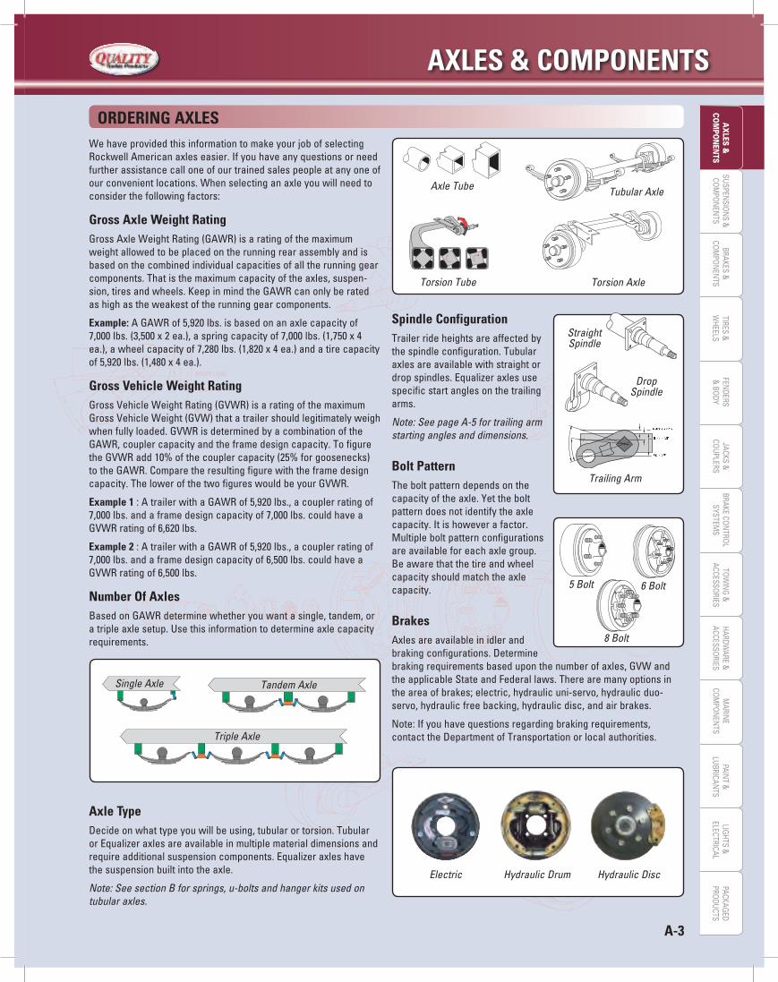
Spindle ConfigurationTrailer ride heights are affected by the spindle configuration. Tubular axles are available with straight or dropspindles.Equalizeraxlesusespecific start angles on the trailing arms.
Note: See page A-5 for trailing arm starting angles and dimensions.
Bolt PatternThe bolt pattern depends on the capacity of the axle. Yet the bolt pattern does not identify the axle capacity.Itishoweverafactor.Multiple bolt pattern configurations are available for each axle group. Be aware that the tire and wheel capacity should match the axle capacity.
BrakesAxlesareavailableinidlerand brakingconfigurations.Determine brakingrequirementsbaseduponthenumberofaxles,GVWandthe applicable State and Federal laws. There are many options in theareaofbrakes;electric,hydraulicuni-servo,hydraulicduo-servo,hydraulicfreebacking,hydraulicdisc,andairbrakes.
Note:Ifyouhavequestionsregardingbrakingrequirements,contacttheDepartmentofTransportationorlocalauthorities.
Axle Tube Tubular Axle
Torsion Tube Torsion Axle
Straight Spindle
Drop Spindle
Trailing Arm
5 Bolt 6 Bolt
8 Bolt
Electric Hydraulic DiscHydraulic Drum

AXLeS & COMPONeNTS
A-4
SUSP
ENSI
ON
S &
COM
PON
ENTS
BRAK
ES &
COM
PON
ENTS
TIRE
S &
WHE
ELS
FEN
DERS
& B
ODY
JACK
S &
COU
PLER
STO
WIN
G &
ACCE
SSO
RIES
PAIN
T &
LUBR
ICAN
TSBR
AKE
CON
TRO
LSY
STEM
SLI
GHT
S &
ELEC
TRIC
ALM
ARIN
ECO
MPO
NEN
TSHA
RDW
ARE
&AC
CESS
ORI
ESPA
CKAG
EDPR
ODU
CTS
AX
LES
&CO
MPO
NEN
TS
The equalizer axle makes leaf spring suspension systems obsolete. Eachspindleisattachedtoatrailingarmwhichrocksupanddownduringroadshock.Thismovementisthentransferredtoasteelinnerbarwithintheaxlebeam.Rubbercordsthenabsorbtheshockfromthetwistinginnerbar.Leafspringshavehighinitialamplitudefollowed with many slowly diminishing oscillations – a very slow return to stability.
Period of Oscillation
Am
plit
ud
e o
f O
scill
atio
n
Damping Control of a Steel Leaf Spring
The equalizer has the same initial amplitude, but see the swift dampening with quick return to stability.
Period of Oscillation
Am
plit
ud
e o
f O
scill
atio
n
Damping Control of the Equalizer
Trailing Arm Spindle
Axle Tube
Rubber Cords
Inner Bar (connects to trailing arm)
THe BeNeFiTS
Superior Performance - The independent action provides greatercontrolandstabilitywhichmakestowingthetrailermucheasier. Wheel vibration is absorbed by the rubber cords.
variable Capacity - Capacitycanbetailoredtoyourrequire-mentsin100lb.increments.
Neat, Clean, Functional - Since the torsion axle mounts directly to the frame, we can provide most any ground-clearance you desire. There are no leaf springs, hangers, u-bolts, etc. to become clogged with mud, snow or ice.
reduced Costs -Withnometaltometalcontact,(nosprings,bolts,shacklestraps),maintenanceisminimal.Theaddedstrength and support supplied by the torsion axle means less stress on your trailer’s frame. The addition of the axle as a cross member eliminates a current cross member resulting in less cost and weight.
easy installation - Top or side mounting is available. Only 4 bolts are needed to mount.
Service/delivery - Excellentservice,delivery,leadtimesandfreight costs are integral to the success of your business. We provide all of these, giving you the greatest chance for success. WiththeEqualizertorsionaxlewemaintainourcommitmenttostay the most respected trailer axle manufacturer in the industry.
Five year Warranty - AfiveyearwarrantyisstandardontheEqualizerbeamandsuspensioncomponentsofthatbeam.
AXLe rANge CAPACiTy
Capacity Range
2,000 lb. Equalizer 500 - 2,000 lbs.
3,500 lb. Equalizer 2,100 - 3,500 lbs.
6,000 lb. Equalizer 3,600 - 6,000 lbs.
7,000 lb. Equalizer 6,100 - 7,000 lbs.
8,000 lb. Equalizer 7,100 - 8,000 lbs.
10,000 lb. Equalizer 8,100 - 10,000 lbs.
THe equALizer TOrSiON AXLe

A-5
AXLeS & COMPONeNTSLIG
HTS &
ELECTRICALPAIN
T &LU
BRICANTS
MARIN
ECO
MPO
NEN
TSHARDW
ARE &ACCESSO
RIESTO
WIN
G &
ACCESSORIES
JACKS &CO
UPLERS
BRAKES &CO
MPO
NEN
TSBRAKE CO
NTRO
LSYSTEM
SSU
SPENSIO
NS &
COM
PON
ENTS
TIRES &W
HEELSFEN
DERS&
BODY
AX
LES &CO
MPO
NEN
TSPACKAG
EDPRO
DUCTS
Note: For replacement purposes the mounting bracket has diagonally slotted side mount holes. This is to accommodate a variety of hole patterns in other side mounted torsion axle systems.Warning: Application of heat to the axle tube will damage the rubber and void the warranty.
1"
AB
Frame
.25"
Top Mounting
.75"
Top Mounting High Profile
C
Frame
.50"
Side Mounting w/SideMount Bracket
Side Mounting High Profilew/Side Mount Bracket
Trailing Arms•Allmeasurementsareininchesandarecalculatedfromthebottomoftheframe.•Aminussignindicatesthatthespindleisabovethetopoftheframebracket.•Allowanadditional3”abovethefullloaddimensionsforfenderclearance.•Add.25”tostartangledimensionsforsidemountingwithkit.•Add.5”tostartangledimensionsforhighprofiletopmounting(except8Kwhichis
standardwithhighprofile).•Add.75”tostartangledimensionsforhighprofilesidemounting.
NO LOAD = Position of trailing arm without a load.FULL LOAD = Position of trailing arm at full capacity load.
22.5° ABOVE
10° ABOVE
22.5° DOWN
45° DOWN
35° DOWN
10° DOWN
0° LEVEL
MOuNTiNg kiTS ANd diMeNSiONS
AXLe TOP MOuNTed Side MOuNTed CAPACiTy kiT PArT# diM. A diM. B BOLT Size kiT PArT # diM. C BOLT Size
Mounting Kits And Dimensions
2,000 lb. 2001-B 8” 1” .5” 2001-S 8.28” .5”
3,500 lb. 3501-B 8” 1.25” .625” 3501-S 8.28” .625”
6,000 lb. 3501-B 9” 1.25” .625” 6001-S 9.3” .75”
7,000 lb. 3501-B 9” 1.25” .625” 7001-S 9.3” .75”
8,000 lb. / 10,000 lb. 8001-B 10.5” 1.25” .75” 8001-S 10.5” .75”
AXLe NuMBer STArT ANgLe POSiTiON
2,000 LB. 3,500 LB. 6,000 LB. 7,000 LB. 8,000 & 10,000 LB.
At No Load -.75” -.56” -.28” -.06” -.63”
22.5° Above At Full Load -2.75” -2.50” -2.25” -2.00” 2.30”
At Shock Load -3.63” -3.43” -3.15” -2.90” 3.20”
At No Load .25” .44” .75” .94” 1.64”
10° Above At Full Load -1.94” -1.69” -1.44” -1.19” -1.50”
At Shock Load -3.00” -2.75” -2.50” -2.25” -2.56”
At No Load 1.25” 1.50” 1.75” 2.00” 2.70”
0° Level At Full Load -1.00” -.75” -.50” -.25” -.56”
At Shock Load -2.19” -1.94” -1.69” -1.44” -1.75”
At No Load 2.30” 2.50” 2.80” 3.06” 4.25”
10° Down At Full Load 0.00” .25” .50” .75” 1.44”
At Shock Load -1.25” -1.06” -.75” -.50” -.81”
At No Load 3.30” 3.50” 3.80” 4.06” 4.75”
22.5° Down At Full Load 1.06” 1.25” 1.56” 1.80” 2.50”
At Shock Load -.25” -.06” .25” .44” 1.25”
At No Load 4.70” 5.95” 5.20” 5.15” 6.14”
35° Down At Full Load 2.80” 3.00” 3.32” 3.50” 5.20”
At Shock Load 1.50” 1.70” 2.00” 2.26” 4.45”
At No Load 5.50” 5.75” 6.00” 6.25” 6.94”
45° Down At Full Load 3.60” 3.80” 4.12” 4.30” 5.0”
At Shock Load 2.30” 2.50” 2.80” 3.06” 3.75”
SHOCK LOAD = Position of trailing arm at extreme shock.Note: 10,000 lb. axle has same start angle as 8,000 lb.

AXLeS & COMPONeNTS
A-6
SUSP
ENSI
ON
S &
COM
PON
ENTS
BRAK
ES &
COM
PON
ENTS
TIRE
S &
WHE
ELS
FEN
DERS
& B
ODY
JACK
S &
COU
PLER
STO
WIN
G &
ACCE
SSO
RIES
PAIN
T &
LUBR
ICAN
TSBR
AKE
CON
TRO
LSY
STEM
SLI
GHT
S &
ELEC
TRIC
ALM
ARIN
ECO
MPO
NEN
TSHA
RDW
ARE
&AC
CESS
ORI
ESPA
CKAG
EDPR
ODU
CTS
AX
LES
&CO
MPO
NEN
TS
TuBuLAr AXLe OverHANgOverhang is the difference between the hubface measurement and the spring center measurement on tubular axles.
TOrSiON AXLe OverHANgOverhang is the difference between the hubface measurement andtheoutsideofbracketmeasurement.
TS = Tubular StraightSS = Square StraightRS = Rectangular StraightTD = Tubular DropSD = Square DropRD = Rectangular Drop
* Maximum Hubface For TS20 & SS20 is 95”** Minimum Hubface For 10K is 69” Maximum Hubface For 10K is 78”
AXLe MiNiMuM TyPe idLer BrAke MAXiMuM
Tubular Axle Overhang Differences
TS20 9.3” 10.75” 15”
SS20 10.75” 10.75” 15”
SD20 15” 15” 19”
TS35 10” 12” 18”
TD35 14” 14” 18”
SS35 10” 13” 19”
RS35 10” 13” 19”
SD/RD35 15” 15” 19”
TS52 13” 13” 18”
TD52 16” 16” 19”
RS52 13.5” 13.5” 19”
RD52 17.5” 17.5” 19”
TS60 13” 13” 18”
TD60 16” 16” 19”
TS70 14” 14” 18”
TD70 16” 16” 18”
TS80 17” 17” 19”
10K-16K 27” 27” 32”
* Short Spindle Option** Extra Short Spindle Option
Equalizer Axle Hubface To Mounting Bracket Overhang Differences
AXLe OverHANg MiNiMuM TyPe MiNiMuM MAXiMuM HuBFACe
EQ20 12.5”/10.5”*/9.5”** 22” 46”
EQ35 12.5” 24” 46”
EQ60 14.5”/14”* 24” 50”
EQ70 14.5”/14”* 28” 50”
EQ80 17.5” 43” 54”
10KEQ 22.5” 38” 66”
Don’t use tire centers! Due to the use of offset wheels, the center to center tire measurement cannot be used to order an axle. The actual hubface must be used.
A-7
AXLeS & COMPONeNTSLIG
HTS &
ELECTRICALPAIN
T &LU
BRICANTS
MARIN
ECO
MPO
NEN
TSHARDW
ARE &ACCESSO
RIESTO
WIN
G &
ACCESSORIES
JACKS &CO
UPLERS
BRAKES &CO
MPO
NEN
TSBRAKE CO
NTRO
LSYSTEM
SSU
SPENSIO
NS &
COM
PON
ENTS
TIRES &W
HEELSFEN
DERS&
BODY
AX
LES &CO
MPO
NEN
TSPACKAG
EDPRO
DUCTS
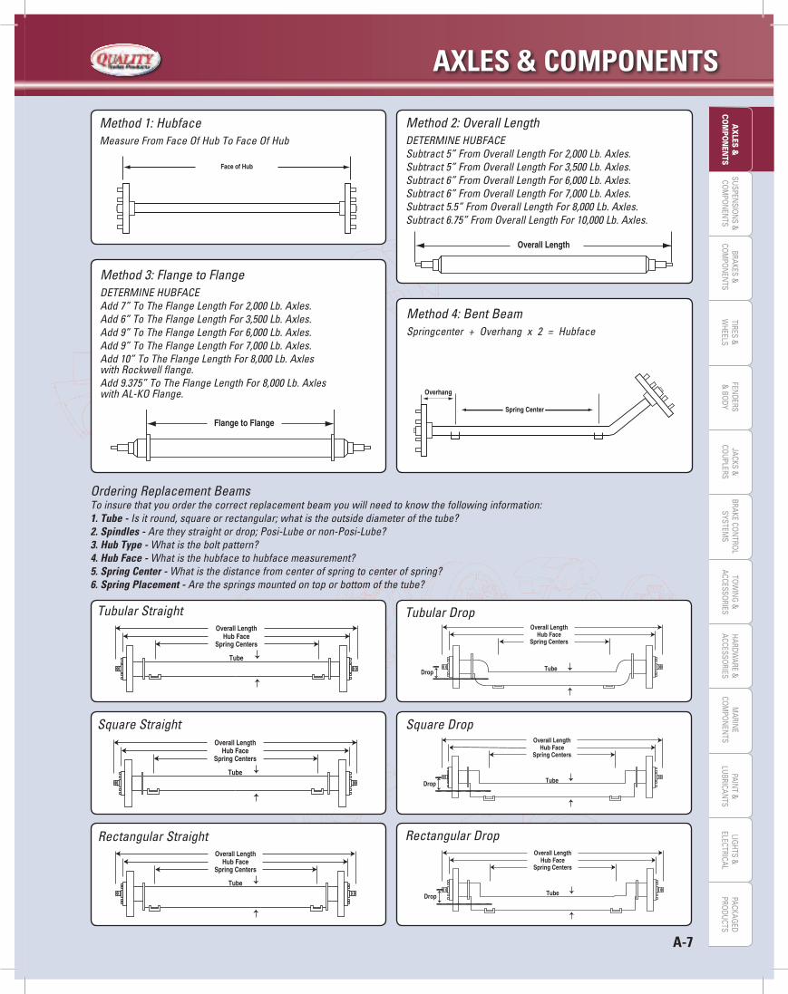
Method 1: HubfaceMeasure From Face Of Hub To Face Of Hub
Method 2: Overall LengthDETERMINE HUBFACESubtract 5” From Overall Length For 2,000 Lb. Axles. Subtract 5” From Overall Length For 3,500 Lb. Axles. Subtract 6” From Overall Length For 6,000 Lb. Axles. Subtract 6” From Overall Length For 7,000 Lb. Axles.Subtract 5.5” From Overall Length For 8,000 Lb. Axles.Subtract 6.75” From Overall Length For 10,000 Lb. Axles.
Method 3: Flange to FlangeDETERMINE HUBFACE Add 7” To The Flange Length For 2,000 Lb. Axles. Add 6” To The Flange Length For 3,500 Lb. Axles. Add 9” To The Flange Length For 6,000 Lb. Axles. Add 9” To The Flange Length For 7,000 Lb. Axles.Add 10” To The Flange Length For 8,000 Lb. Axleswith Rockwell flange.Add 9.375” To The Flange Length For 8,000 Lb. Axleswith AL-KO Flange.
Method 4: Bent BeamSpringcenter + Overhang x 2 = Hubface
Ordering Replacement Beams To insure that you order the correct replacement beam you will need to know the following information:1. Tube - Is it round, square or rectangular; what is the outside diameter of the tube?2. Spindles - Are they straight or drop; Posi-Lube or non-Posi-Lube?3. Hub Type - What is the bolt pattern?4. Hub Face - What is the hubface to hubface measurement?5. Spring Center - What is the distance from center of spring to center of spring?6. Spring Placement - Are the springs mounted on top or bottom of the tube?
Tubular Drop
Square Straight Square Drop
Rectangular Straight Rectangular Drop
Tubular Straight
AXLeS & COMPONeNTS
A-8
SUSP
ENSI
ON
S &
COM
PON
ENTS
BRAK
ES &
COM
PON
ENTS
TIRE
S &
WHE
ELS
FEN
DERS
& B
ODY
JACK
S &
COU
PLER
STO
WIN
G &
ACCE
SSO
RIES
PAIN
T &
LUBR
ICAN
TSBR
AKE
CON
TRO
LSY
STEM
SLI
GHT
S &
ELEC
TRIC
ALM
ARIN
ECO
MPO
NEN
TSHA
RDW
ARE
&AC
CESS
ORI
ESPA
CKAG
EDPR
ODU
CTS
AX
LES
&CO
MPO
NEN
TS
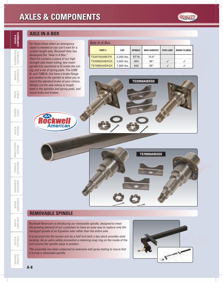
For those times when an emergency repair is needed or you can’t wait for a custom length axle, Rockwell Axle has developed the “Axle In A Box.” \Each kit contains a piece of our high strength axle beam tubing, two insert spindle kits machined to fit inside the tub-ing, and a set of spring pads. The 3,500 lb. and 7,000 lb. kits have a brake flange pre-welded to the spindle to allow you to mount the standard brake of your choice. \Simply cut the axle tubing to length, weld in the spindles and spring pads, and mount hubs and brakes.
AXLe iN A BOX
reMOvABLe SPiNdLe
TS35950AiBXqX
Axle In A Box
PArT # CAP SPiNdLe MAX HuBFACe POSi-LuBe BrAke FLANge
TS20755AIBCPX 2,200 lbs. BT16 75.5”
TS35950AIBXQX 3,500 lbs. #84 95” 3 3
TS70950AIBXQX 7,000 lbs. #42 95” 3 3
Rockwell American is introducing our removable spindle, designed to meet the growing demand of our customers to have an easy way to replace only the damaged spindle of an Equalizer axle rather than the entire axle.
It is secured into the torsion arm by a half inch bolt; a key stock provides axial locating. As an extra safety precaution a retaining snap ring on the inside of the arm insures the spindle stays in position.
This assembly has been subjected to extensive salt spray testing to insure that it is truly a removable spindle.
TS70950AiBXqX
A-9
AXLeS & COMPONeNTSLIG
HTS &
ELECTRICALPAIN
T &LU
BRICANTS
MARIN
ECO
MPO
NEN
TSHARDW
ARE &ACCESSO
RIESTO
WIN
G &
ACCESSORIES
JACKS &CO
UPLERS
BRAKES &CO
MPO
NEN
TSBRAKE CO
NTRO
LSYSTEM
SSU
SPENSIO
NS &
COM
PON
ENTS
TIRES &W
HEELSFEN
DERS&
BODY
AX
LES &CO
MPO
NEN
TSPACKAG
EDPRO
DUCTS
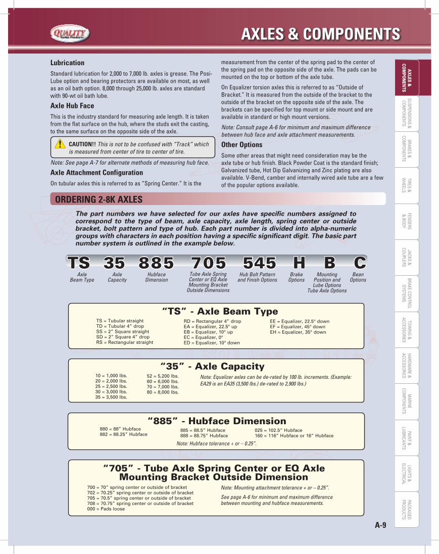
OrderiNg 2-8k AXLeSThe part numbers we have selected for our axles have specific numbers assigned to correspond to the type of beam, axle capacity, axle length, spring center or outside bracket, bolt pattern and type of hub. Each part number is divided into alpha-numeric groups with characters in each position having a specific significant digit. The basic part number system is outlined in the example below.
10 = 1,000 lbs.20 = 2,000 lbs.25 = 2,500 lbs.30 = 3,000 lbs.35 = 3,500 lbs.
Note: Equalizer axles can be de-rated by 100 lb. increments. (Example: EA29 is an EA35 (3,500 lbs.) de-rated to 2,900 lbs.)
“35” - Axle Capacity52 = 5,200 lbs.60 = 6,000 lbs.70 = 7,000 lbs.80 = 8,000 lbs.
LubricationStandardlubricationfor2,000to7,000lb.axlesisgrease.ThePosi-Lubeoptionandbearingprotectorsareavailableonmost,aswellasanoilbathoption.8,000through25,000lb.axlesarestandardwith90-wtoilbathlube.
Axle Hub FaceThisistheindustrystandardformeasuringaxlelength.Itistakenfrom the flat surface on the hub, where the studs exit the casting, to the same surface on the opposite side of the axle.
Note: See page A-7 for alternate methods of measuring hub face.
Axle Attachment ConfigurationOntubularaxlesthisisreferredtoas“SpringCenter.”Itisthe
measurement from the center of the spring pad to the center of the spring pad on the opposite side of the axle. The pads can be mounted on the top or bottom of the axle tube.
OnEqualizertorsionaxlesthisisreferredtoas“OutsideofBracket.”Itismeasuredfromtheoutsideofthebrackettotheoutsideofthebracketontheoppositesideoftheaxle.Thebracketscanbespecifiedfortopmountorsidemountandareavailable in standard or high mount versions.
Note: Consult page A-6 for minimum and maximum difference between hub face and axle attachment measurements.
Other OptionsSome other areas that might need consideration may be the axletubeorhubfinish.BlackPowderCoatisthestandardfinish;Galvanizedtube,HotDipGalvanizingandZincplatingarealsoavailable. V-Bend, camber and internally wired axle tube are a few of the popular options available.
CAuTiON!! This is not to be confused with “Track” which is measured from center of tire to center of tire.
TS = Tubular straightTD = Tubular 4” dropSS = 2” Square straightSD = 2” Square 4” dropRS = Rectangular straight
RD = Rectangular 4” dropEA = Equalizer, 22.5° upEB = Equalizer, 10° upEC = Equalizer, 0°ED = Equalizer, 10° down
“TS” - Axle Beam TypeEE = Equalizer, 22.5° downEF = Equalizer, 45° downEH = Equalizer, 35° down
700 = 70” spring center or outside of bracket702 = 70.25” spring center or outside of bracket705 = 70.5” spring center or outside of bracket708 = 70.75” spring center or outside of bracket000 = Pads loose
“705” - Tube Axle Spring Center or EQ Axle Mounting Bracket Outside Dimension
Note: Mounting attachment tolerance + or – 0.25”.
See page A-6 for minimum and maximum difference between mounting and hubface measurements.
TS 35 885 705 545 H B CAxle
Beam TypeAxle
CapacityTube Axle Spring Center or EQ Axle Mounting Bracket
Outside Dimensions
Hub Bolt Pattern and Finish Options
Brake Options
MountingPosition andLube Options
Tube Axle Options
Bean Options
Hubface Dimension
880 = 88” Hubface882 = 88.25” Hubface
Note: Hubface tolerance + or – 0.25”.
885 = 88.5” Hubface888 = 88.75” Hubface
“885” - Hubface Dimension025 = 102.5” Hubface160 = 116” Hubface or 16” Hubface

AXLeS & COMPONeNTS
A-10
SUSP
ENSI
ON
S &
COM
PON
ENTS
BRAK
ES &
COM
PON
ENTS
TIRE
S &
WHE
ELS
FEN
DERS
& B
ODY
JACK
S &
COU
PLER
STO
WIN
G &
ACCE
SSO
RIES
PAIN
T &
LUBR
ICAN
TSBR
AKE
CON
TRO
LSY
STEM
SLI
GHT
S &
ELEC
TRIC
ALM
ARIN
ECO
MPO
NEN
TSHA
RDW
ARE
&AC
CESS
ORI
ESPA
CKAG
EDPR
ODU
CTS
AX
LES
&CO
MPO
NEN
TS TS 35 885 705 545 H B CAxle
Beam TypeAxle
CapacityTube Axle Spring Center or EQ Axle Mounting Bracket
Outside Dimensions
Hub Bolt Pattern and Finish Options
Brake Options
MountingPosition andLube Options
Tube Axle Options
Bean Options
Hubface Dimension
440 = 4 on 4” bolt545 = 5 on 4.5” bolt54G = 5 on 4.5” bolt, Galvanized54W = 5 on 4.5” bolt, 6.25” flange (2K idler)547 = 5 on 4.75” bolt550 = 5 on 5.0” bolt555 = 5 on 5.5” bolt655 = 6 on 5.5” bolt65L = 6 on 5.5” bolt, Long Studs (5.2K - 6K idler)65G = 6 on 5.5” bolt, Galvanized
“545” - Hub Bolt Pattern and Finish Options66R = 6 on 6” bolt (RV Hub)660 = 6 on 6” bolt (Agricultural Hub)865 = 8 on 6.5” bolt86L = 8 on 6.5” bolt, Long .625” Studs (6K - 7K idler)86G = 8 on 6.5” bolt, Galvanized86T = 8 on 6.5” bolt, 9⁄16” stud (7K)880 = 8 on 8.0” bolt (Agricultural Hub)
Note: Double lip seals standard on all hubs.Zinc studs standard on 2K thru 7K.Axle Beam Only will not have a Hub Bolt Pattern designator.
I = Idler with Brake Flange (2K standard without Brake Flange)C = Idler or beam without Brake FlangeE = Electric brakeW = Electric brake pre-wired axle or pre-wired beamL = Electric brake pre-wired with Brake Wire ProtectorJ = Electric brake with Brake Wire ProtectorA = Electric brake with Long Lead WireQ = Electric brake with Brake Wire Protector and Long Lead WireH = Hydraulic brake, Uni-Servo3 = Hydraulic brake, Duo-ServoF = Hydraulic brake, Free-BackingP = Hydraulic brake, Uni-Servo PremierY = Hydraulic brake, Free-Backing Premier4 = Hydraulic Disc brake, Cadmium Plated Disc & Calipers
“H” Brake Options2 = Hydraulic Disc brake, E-Coat6 = Hydraulic Disc brake, Stainless Disc & Calipers 5 = Hydraulic Disc brake, Integral Hub, Cadmium Plated Disc & Calipers8 = Hydraulic Disc brake, Integral Hub E-CoatX = None; axle beam with Brake Flange (2K standard without Brake Flange)B = Electric Self-Adj BrakeD = Electric Self-Adj Brake w/ Pre-Wired BeamM = Electric Self-Adj Brake w/ Brake Wire ProtectorR = Electric Self-Adj Brake w/ Pre-Wired Beam & Brake Wire ProtectorK = Electric Self-Adj Brake w/ Long Lead WiresN = Electric Self-Adj Brake w/ Brake Wire Protector & Long Lead Wires
P = Pads loose / Grease LubeQ = Pads loose / Posi-LubeR = Pads loose / Bearing ProtectorsX = Pads loose / Oil BathA = Bottom mount / Grease LubeB = Bottom mount / Posi-LubeC = Bottom mount / Bearing ProtectorsS = Bottom mount / Oil Bath
“B” Mounting Position and Lube Options Tube Axle Options
D = Top mount / Grease LubeE = Top mount / Posi-LubeF = Top mount / Bearing ProtectorsT = Top mount / Oil Bath- = Top & Bottom Mounted Pads / Grease Lube6 = Top & Bottom Mounted Pads / Posi-Lube
Note: Oil Bath 8 bolt onlyl
D = Top mount / Grease LubeE = Top mount / Posi-LubeF = Top mount / Bearing ProtectorsT = Top mount / Oil Bath7 = Side Mount / Attaching Kit Mounted / Bearing ProtectorsG = Side mount / Grease LubeH = Side mount / Posi-LubeI = Side mount / Bearing ProtectorsU = Side mount / Oil BathJ = High top mount / Grease LubeK = High top mount / Posi-LubeL = High top mount / Bearing ProtectorsV = High top mount / Oil Bath
Equalizer Axle OptionsM = High side mount / Grease LubeN = High side mount / Posi-LubeO = High side mount / Bearing ProtectorsW = High side mount / Oil Bath2 = Side mount / Attaching Kit Mounted / Grease Lube 3 = High side mount / Attaching Kit Mounted / Grease LubeY = Side mount / Attaching Kit Mounted / Posi-Lube Z = High side mount / Attaching Kit Mounted / Posi-Lube4 = Side mount / Attaching Kit Mounted / Oil Bath5 = High side mount / Attaching Kit Mounted / Oil Bath1 = High side mount / Attaching Kit Mounted / Bearing Protectors
Note: Oil Bath 8 bolt onlyl
X = No CamberC = Cambered beamG = No Camber / Galvanized beam4 = No Camber / Galvanized beam / Removable SpindleB = Cambered / Galvanized beam5 = Cambered / Galvanized beam / Removable SpindleF = Cambered / Galvanized beam / Double Mounting BracketsP = Cambered / Double Mounting BracketsH = V-Bend Beam3 = V-Bend Beam / Removable Spindle
“C” Beam OptionsK = V-Bend / Galvanized Beam6 = V-Bend / Galvanized Beam / Removable SpindleL = V-Bend / Galvanized Beam / Double Mounting BracketsM = Cambered Beam / Short Spindle (2K-7K EQ, Except 3.5K)J = No Camber / Short Spindle (2K-7K EQ, Except 3.5K)1 = No Camber / Removable Spindle2 = Cambered / Removable SpindleT = Cambered/Galvanized Tube OnlyS = No Camber/Galvanized Tube OnlyQ = V-Bend/Galvanized Tube Only

A-11
AXLeS & COMPONeNTSLIG
HTS &
ELECTRICALPAIN
T &LU
BRICANTS
MARIN
ECO
MPO
NEN
TSHARDW
ARE &ACCESSO
RIESTO
WIN
G &
ACCESSORIES
JACKS &CO
UPLERS
BRAKES &CO
MPO
NEN
TSBRAKE CO
NTRO
LSYSTEM
SSU
SPENSIO
NS &
COM
PON
ENTS
TIRES &W
HEELSFEN
DERS&
BODY
AX
LES &CO
MPO
NEN
TSPACKAG
EDPRO
DUCTS
10K 740 470 865 E B S XMounting Dimension
AxleCapacity
Bolt Pattern, Lube and Pilot Options
Brake Options
MountingPosition
Brake Designation
Spring Options
Hubface Dimension
OrderiNg 10k equALizer ANd 10k-16k TuBuLAr AXLeS
10K = 10,000 lbs. 12K = 12,000 lbs. 16K = 16,000 lbs.
“10K” Axle Capacity
740 = 74” Hubface742 = 74.25” Hubface
“740” Hubface Dimension745 = 74.5” Hubface748 = 74.75” Hubface
865 = 8 on 6.5” Bolt Pattern, Oil Bath, Hub Piloted With 4.88” Pilot86G = 8 on 6.5” Bolt Pattern, Grease Lube, Hub Piloted With 4.88” Pilot86C = 8 on 6.5” Bolt Pattern, Oil Bath, Hub Piloted With 4.75” Pilot86D = 8 on 6.5” Bolt Pattern, Grease Lube, Hub Piloted With 4.75” Pilot810 = 8 on 275mm Bolt Pattern, Oil Bath, Hub Piloted, 221mm Pilot108 = 10 on 8.75” Bolt Pattern, Oil Bath, Hub Piloted, 6.5” Pilot
“865” Bolt Pattern, Lube and Pilot Options
470 = 47” Spring Center472 = 47.25” Spring Center
“470” Mounting Dimension 475 = 47.5” Spring Center478 = 47.75” Spring Center
I = IdlerE = Electric BrakeH = Hydr Aulic Duo Servo BrakeD = Hydraulic Disc BrakeX = Beam Only (Requires Brake Type In Last Character Of Part Number)
“E” Brake Options
B = Bottom MountA = Bottom Mount / Adjustable Spring PadsT = Top Mount
“B” Mounting Position E = Top Mount / Adjustable Spring PadsP = Pads Loose
S = 2.5” Wide Spring Mounted
“S” Spring OptionsX = No Springs
“X” Brake Flange DesignationX = Rockwell American BrakeH = Hayes/Al-Ko Brake Flange on Beam
Q = Rockwell Brake Flange on BeamW = Warner Brake Flange on Beam

AXLeS & COMPONeNTS
A-12
SUSP
ENSI
ON
S &
COM
PON
ENTS
BRAK
ES &
COM
PON
ENTS
TIRE
S &
WHE
ELS
FEN
DERS
& B
ODY
JACK
S &
COU
PLER
STO
WIN
G &
ACCE
SSO
RIES
PAIN
T &
LUBR
ICAN
TSBR
AKE
CON
TRO
LSY
STEM
SLI
GHT
S &
ELEC
TRIC
ALM
ARIN
ECO
MPO
NEN
TSHA
RDW
ARE
&AC
CESS
ORI
ESPA
CKAG
EDPR
ODU
CTS
AX
LES
&CO
MPO
NEN
TS
22K 715 205 12O B C B XCam
DimensionAxle
CapacityHub, Bolt Pattern, and Drum Options
Brake Options
AdjusterOptions
Misc.Options
Lubrication Options
Track Dimension
OrderiNg 22.5k-30k AXLeS
“22K” Axle Capacity 22.5K22K = 22,500 lbs. w/.50” wall tube 25K = 25,000 lbs. w/.62” wall tube 30K = 30,000 lbs. w/.75 Wall Tube
Note: Higher capacities available on a special order basis.
“715” Track Dimension715 = 71.5” Track (96” Overall) 775 = 77.5” Track (102” Overall) 800 = 80.0” Track (104.5” Overall)
“205” Cam Dimension175 = 17.4375” Cam Length - Short 205 = 20.5” Cam Length - Intermediate 240 = 24.0” Cam Length - Long
“120” Hub, Bolt Pattern, and Drum Options18I = 10 on 8.75” / Inboard Mount Drum18O = 10 on 8.75” / Outboard Mount Drum11I = 10 on 11.25” / Inboard Mount Drum11O = 10 on 11.25” / Outboard Mount Drum12I = 10 on 285.75mm / Inboard Mount Drum12O = 10 on 285.75mm / Outboard Mount DrumX12 = No Hub And Drum / 12.25” X 7.5” BrakeX16 = No Hub And Drum / 16.5” X 7” Brake
1AB = 10 on 11.25” / Aluminum Hub / Centrifuse Drum1AP = 10 on 285mm / Aluminum Hub / Centrifuse Drum1WB = 10 on 11.25” / Duralite Hub / Centrifuse Drum1WH = 10 on 285mm / Duralite Hub / Centrifuse Drum1WK = 10 on 285 mm / Duralite Hub / KIC Cast Drum1WX = Duralite Hub / No DrumOOO = No Hubs
“B” Brake OptionsNote: Service Chamber – Off Highway, (no parking brake) or Tag Axle Spring Brake – Over the Highway, includes parking brake ABS – Mandatory over the highway (uses el-24 lead) Non ABS – Off highway, no lead needed
A = Standard Type 30 Service Chambers w/o ABS Sensor LeadsB = Type 30/30 Spring Brake w/o ABS Sensor Leads C = Standard Type 30 Service Chambers with ABS Sensor Leads D = Type 30/30 Spring Brake with ABS Sensor LeadsE = Type 24/24 Spring Brake w/o ABS Sensor LeadsF = Type 24/24 Spring Brake with ABS Sensor LeadsG = Type 24 Service ChambersH = Long LifeX = None
“C” Adjuster OptionsA = Straight Manual Slack AdjustersB = Straight Automatic Slack Adjusters-GuniteC = Straight Automatic Slack Adjusters-MeritorD = Curved Automatic Slack Adjusters
E = Curved Manual Slack AdjustersF = Equals Straight Automatic Slack Adjuster-Gunite 6”G = Equals Straight Automatic Slack Adjuster-Meritor 6”X = None
“B” Lubrication OptionsA = CR Seal and Oil CapB = Stemco Seal and Oil Cap
C = Pro Torque-StemcoX = None
“X” Miscellaneous OptionsA = Budd Nuts for Steel Inner and Aluminum Outer WheelsB = Budd Nuts for Aluminum Inner and Aluminum Outer WheelsC = Wheel Nuts for Super Single Aluminum WheelsD = Budd Nuts for Steel Inner and Steel Outer Wheels
E = Hub Piloted Wheels Nuts for 33mmZ = Q-Plus Brakes w/Hub Pilot Wheel NutsX = No Nuts

A-13
AXLeS & COMPONeNTSLIG
HTS &
ELECTRICALPAIN
T &LU
BRICANTS
MARIN
ECO
MPO
NEN
TSHARDW
ARE &ACCESSO
RIESTO
WIN
G &
ACCESSORIES
JACKS &CO
UPLERS
BRAKES &CO
MPO
NEN
TSBRAKE CO
NTRO
LSYSTEM
SSU
SPENSIO
NS &
COM
PON
ENTS
TIRES &W
HEELSFEN
DERS&
BODY
AX
LES &CO
MPO
NEN
TSPACKAG
EDPRO
DUCTS
*Note: for Posi-Lube spindles
2k AXLe ASSeMBLieS ANd COMPONeNTS
2,000 LB. Axle Component Parts
PArT # deSCriPTiON diAgrAM #
4-29 Brake Flange, 4-Hole (Optional) 1
15192TB Grease Seal, Double Lip, 2 1.50” - BT16
12192TB Grease Seal, Double Lip, 1.25” - 2 BT8 (Optional)
L-44649 Inner Bearing, 1.0625” ID - BT16 3
L-44643 Inner Bearing, 1” ID - BT8 (Optional) 3
L-44610 Inner Race, 1.98” OD 4
4758-Z Wheel Stud, .5” – 20 X 1.625” (Idler) 5
L-44610 Outer Race, 1.98” OD 6
L-44649 Outer Bearing, 1.0625” ID - BT16 7
L-44643 Outer Bearing, 1” ID - BT8 (Optional) 7
4753 Spindle Washer, 1” 8
4754 Spindle Nut, 1” – 14 9
4755 Cotter Pin, .125” X 2” 10
21-3 Grease Cap, 1.98” OD 11
4756 Cone Wheel Nut, .5” – 20 X 60° 12
21-3-PL* Grease Cap, Posi–Lube 1.98” OD 13
RP-100* Rubber Plug, Posi–Lube Cap 14
Note: Cupped & studded hubs include the hub, wheel studs and inner & outer race/cups. Complete hubs include the cupped and studded hub, inner & outer bearings, seal, lug nuts and dust cap/grease cap.
Add “PL” to the end of the assembly part number for Posi-lube components.
2,000 LB. Hubs and Drums PArT #
COMPLeTe HuB HuB, CuPPed & STudded deSCriPTiON BOLT PATTerN SPiNdLe
88440 88440-1 Idler Hub 4 on 4” BT8
88440-BT16 88440-1 Idler Hub 4 on 4” BT16
88545 88545-1 Idler Hub 5 on 4.5” BT8
88545-BT16 88545-1 Idler Hub 5 on 4.5” BT16
88545W 88545W-1 Idler Hub 5 on 4.5” BT8
88545W-BT16 88545W-1 Idler Hub 5 on 4.5” BT16
98440 98440-1 Brake Drum 4 on 4” BT8
98440-BT16 98440-1 Brake Drum 4 on 4” BT16
98545 98545-1 Brake Drum 5 on 4.5” BT8
98545-BT16 98545-1 Brake Drum 5 on 4.5” BT16
88440-1
98545-1

AXLeS & COMPONeNTS
A-14
SUSP
ENSI
ON
S &
COM
PON
ENTS
BRAK
ES &
COM
PON
ENTS
TIRE
S &
WHE
ELS
FEN
DERS
& B
ODY
JACK
S &
COU
PLER
STO
WIN
G &
ACCE
SSO
RIES
PAIN
T &
LUBR
ICAN
TSBR
AKE
CON
TRO
LSY
STEM
SLI
GHT
S &
ELEC
TRIC
ALM
ARIN
ECO
MPO
NEN
TSHA
RDW
ARE
&AC
CESS
ORI
ESPA
CKAG
EDPR
ODU
CTS
AX
LES
&CO
MPO
NEN
TS
2,000 LB. Brakes
PArT # deSCriPTiON
4740-L Electric, 7” X 1.25”, LH
4740-R Electric, 7” X 1.25”, RH
4712-L Hydraulic, 7” X 1.75”, LH
4712-R Hydraulic, 7” X 1.75”, RH
2/RCMHS-8-2-E Hydraulic Disc, 8”, Integral Hub, 5 On 4.5”, E-Coat, Pair
2/RCMHS-8-2-DAC Hydraulic Disc, 8”, Integral Hub, 5 On 4.5”, Dacromet-Coat, Pair
2,000 LB. Hanger Kits
PArT # deSCriPTiON SPriNg TyPe
4103 Single Axle Double Eye
4103-L Single Axle, Tall Double Eye
4104 Single Axle, .5625” Eye Bolt Slipper
4105 Single Axle, .50” Eye Bolt Slipper
4102 Tandem Axle Double Eye
4102-A Tandem Axle, Tall Double Eye
4101 Triple Axle Double Eye
4101-A Triple Axle, Tall Double Eye
AP (Attaching Parts) Kits for EQ Axles
PArT # TOP/Side MOuNT
Note: Side mount kits include nuts, bolts, washers, and mounting brackets.Top mount kits include nuts, bolts and washers only.
2001-B Top mount
2001-S Side mount
2,000 LB. U-Bolt Kits
PArT # deSCriPTiON TuBe diAMeTer
4205 Round Beam 1.75”
4205-ZP Round Beam, Zinc Plated 1.75”
4206 Square Beam 1.75”
4206-ZP Square Beam, Zinc Plated 1.75”
4203 Square Beam 2”
4203-ZP Square Beam, Zinc Plated 2”
2,000 LB. Tubular and Torsion Axle Specifications and Options
Std. = Standard Opt. = Option X = Not Available
SPeCiFiCATiONS/ OPTiONS 2k 2k eq
LuBriCATiON
Grease Lube Std. Std.
Posi-Lube Opt. Opt.
Bearing Protectors Opt. Opt.
STudS
.5” Zinc Studs Std. Std.
BOLT CirCLe PATTerNS
4 On 4” Opt. Opt.
5 On 4.5” Circle With 5.75” Flange Opt. Opt.
5 On 4.5” Circle With 6.25” Flange Opt. Opt.
HuBS
Black Painted Hubs Std. Std.
Galvanized Hubs Opt. Opt.
SeALS
Double lip seal Std. Std.
BrAkeS
Electric Brake Opt. Opt.
Hydraulic Drum Brake, Uni-Servo Opt. Opt.
Hydraulic Disc Brake Opt. Opt.
Brake Flange On Idler Axle Opt. Opt.
Pre-Wired Axle Tubing Opt. Opt.
SPiNdLeS
BT-16 Spindle Std. Std.
Straight Spindle Std. Std.
4” Drop Spindle (2” Sq. Tube Only) Opt. X
3” Drop Spindle (2” Sq. Tube Only) Opt. X
2” Drop Spindle (2” Sq. Tube Only) Opt. X
AXLe MATeriALS
1.75” High Strength Round Tube Std. X
2.173” Round Corner Square Tube X Std.
2” X 2” Square Tube Opt. X
Cambered Axle Tubing Std. Std.
Galvanized Axle Beam Opt. Opt.
V-Bend Tubing X Opt.
eq ATTACHiNg BrACkeTS
High Mount Brackets +2” X Opt.
High Mount Brackets +3” X Opt.
Common Leaf Springs For 2,000 LB. Axles
PArT # STyLe LeNgTH CAPACiTy NO. OF LeAveS WidTH
4332-11 Double eye 26” 1,100 lbs. 3 1.75”
4332-12 Double eye 25.25” 1,325 lbs. 3 1.75”
4332-13 Double eye 20” 1,500 lbs. 3 1.75”
4332-13L Double eye 23.25” 1,750 lbs. 3 1.75”
4321-5 Slipper 24” 500 lbs. 2 1.75”
4331-7 Slipper 24” 750 lbs. 3 1.75”
4341-10 Slipper 24” 1,000 lbs. 4 1.75”
4351-12 Slipper 24” 1,300 lbs. 5 1.75”
Note: For additional spring options see pages B-6 Thru B-8.

A-15
AXLeS & COMPONeNTSLIG
HTS &
ELECTRICALPAIN
T &LU
BRICANTS
MARIN
ECO
MPO
NEN
TSHARDW
ARE &ACCESSO
RIESTO
WIN
G &
ACCESSORIES
JACKS &CO
UPLERS
BRAKES &CO
MPO
NEN
TSBRAKE CO
NTRO
LSYSTEM
SSU
SPENSIO
NS &
COM
PON
ENTS
TIRES &W
HEELSFEN
DERS&
BODY
AX
LES &CO
MPO
NEN
TSPACKAG
EDPRO
DUCTS
3.5k AXLe ASSeMBLieS ANd COMPONeNTS
*Note: for Posi-Lube spindles
3,500 LB. Axle Component Parts
PArT # deSCriPTiON diAgrAM #
Note: Cupped & studded hubs include the hub, wheel studs and inner & outer race/cups. Complete hubs include the cupped and studded hub, inner & outer bearings, seal, lug nuts and dust cap/grease cap.
Add “PL” to the end of the assembly part number for Posi-lube components.
3,500 LB. Hubs and Drums
PArT #
COMPLeTe HuB HuB, CuPPed deSCriPTiON BOLT PATTerN
& STudded
84545 84545-1 Idler Hub 5 on 4.5”
845475 845475-1 Idler Hub 5 on 4.75”
84550 84550-1 Idler Hub 5 on 5”
84555 84555-1 Idler Hub 5 on 5.5”
84655 84655-1 Idler Hub 6 on 5.5”
94545 94545-1 Brake Drum 5 on 4.5”
945475 945475-1 Brake Drum 5 on 4.75”
94550 94550-1 Brake Drum 5 on 5”
94555 94555-1 Brake Drum 5 on 5.5”
94655 94655-1 Brake Drum 6 on 5.5”
4-12 Brake Flange, 4-hole 1
171255TB Grease Seal, Double Lip, 1.719” 2
L-68149 Inner Bearing, 1.375” ID 3
L-68111 Inner Race, 2.362” OD 4
4759-Z Wheel Stud, .5”– 20 x 1.8125” 5
4759-20-Z Wheel Stud, .5”– 20 x 2” -
L-44610 Outer Race, 1.98” OD 6
L-44649 Outer Bearing, 1.0625” ID 7
4753 Spindle Washer, 1” 8
4754 Spindle Nut, 1” – 14 9
4755 Cotter Pin, .125” x 2” 10
21-3 Grease Cap, 1.98” OD 11
4756 Cone Wheel Nut, .5” – 20 x 60° 12
21-3-PL* Grease Cap, Posi–Lube 1.98” OD 13
RP-100* Rubber Plug, Posi–Lube Cap 14
84545-1
94545-1
FrACTiON deCiMAL
FRACTION TO DECIMAL CONVERSION CHART
1/16 1/8 9/64 5/32 3/16 11/64 13/64 1/4 5/16 3/8 7/16 1/2 9/16 5/8 11/16 3/4 13/16 7/8 15/16.0625 .1250 .140625 .15625 .1875 .171875 .203125 .2500 .3125 .3750 .4375 .5000 .5625 .6250 .6875 .7500 .8125 .8750 .9375

AXLeS & COMPONeNTS
A-16
SUSP
ENSI
ON
S &
COM
PON
ENTS
BRAK
ES &
COM
PON
ENTS
TIRE
S &
WHE
ELS
FEN
DERS
& B
ODY
JACK
S &
COU
PLER
STO
WIN
G &
ACCE
SSO
RIES
PAIN
T &
LUBR
ICAN
TSBR
AKE
CON
TRO
LSY
STEM
SLI
GHT
S &
ELEC
TRIC
ALM
ARIN
ECO
MPO
NEN
TSHA
RDW
ARE
&AC
CESS
ORI
ESPA
CKAG
EDPR
ODU
CTS
AX
LES
&CO
MPO
NEN
TS 3,500 LB. Brakes
PArT # deSCriPTiON
4701-L Electric, 10” X 2.25”, LH
4701-R Electric, 10” X 2.25”, RH
4701-LA Electric, 10” X 2.25”, LH, Auto Adjusting
4701-RA Electric, 10” X 2.25”, RH, Auto Adjusting
4710-L Hydraulic, 10” X 2.25”, LH
4710-R Hydraulic, 10” X 2.25”, RH
40716 Hydraulic freebacking, 10” X 2.25”, LH
40715 Hydraulic freebacking, 10” X 2.25”, RH
44454 Hydraulic premier, 10” X 2.25”, LH
44453 Hydraulic premier, 10” X 2.25”, RH
44235 Hydraulic freebacking premier, 10” X 2.25”, LH
44234 Hydraulic freebacking premier, 10” X 2.25”, RH
2/RCMHS-8-3-E Hydraulic disc, 8”, Integral Hub, 5 on 4.5”,
E-coat, pair, 10”-13” Wheel
2/RCMHS-8-3-DAC Hydraulic disc, 8”, Integral Hub, 5 on 4.5”,
Dacromet-coat , pair, 10”-13” Wheel
2/HRCM-10-E Hydraulic disc, 10”, Integral Hub, E-coat, pair
2/HRCM-10-DAC Hydraulic disc, 10”, Integral Hub, Dacromet, pair
2/HRCM-10-DAC-SS Hydraulic disc, 10”, Integral Hub, Stainless Calipers,
Dacromet Rotors, & Mntg Brkts, pair
2/RCM-10-E Hydraulic disc, 10”, E-coat, pair
2/RCM-10-DAC Hydraulic disc, 10”, Dacromet-coat, pair
2/RCM-10-DAC-SS Hydraulic disc, 10”, Stainless Calipers,
Dacromet Rotors, & Mntg Brkts, pair
2/RCM-10-SS Hydraulic disc, 10”, Stainless Rotors,
Calipers & Mntg Brkts, pair
Note: 3,500 lb. Hydraulic Disc Brakes are only available in 5 on 4.5” bolt pattern
3,500 LB. Hanger Kits
PArT # deSCriPTiON SPriNg TyPe
4103 Single axle Double eye
4103-L Single axle, tall Double eye
4104 Single axle Slipper
4105 Single axle, .5” eye Slipper
4102 Tandem axle Double eye
4102-A Tandem axle, tall Double eye
4101 Triple axle Double eye
4101-A Triple axle, tall Double eye
AP (Attaching Parts) Kits For EQ Axles
Note: Side mount kits include nuts, bolts,
washers, and mounting brackets.
Top mount kits include nuts, bolts and
washers only.
PArT # TOP/Side MOuNT
3501-B Top mount
3501-S Side mount
3,500 LB. U-Bolt Kits
PArT # deSCriPTiON TuBe diAMeTer
4202 Round Beam .4375” 2.375”
4202-HD Round beam .5” 2.375”
4202-ZP Round Beam, Zinc Plated 2.375”
4203 Square Beam 2”
4203-ZP Square Beam, Zinc Plated 2”
4290-L Square Beam 2.5”
4203-L Rectangular Beam 2” x 3”
4203-LZP Rectangular Beam, Zinc Plated 2” x 3”
Common Leaf Springs for 3,500 LB. Axles
PArT # STyLe LeNgTH CAPACiTy (eA) NO. OF LeAveS WidTH
Note: For additional spring options see pages B-6 Thru B-8.
4342-16 Double eye 26” 1,600 lbs. 4 1.75“
4342-17 Double eye 25.25” 1,750 lbs. 4 1.75“
4332-18 Double eye 25.25” 1,850 lbs. 3 1.75“
4341-17 Slipper 29” 1,750 lbs. 5 1.75“
4351-23 Slipper 24” 2,300 lbs. 4 1.75“
FrACTiON deCiMAL
FRACTION TO DECIMAL CONVERSION CHART
1/16 1/8 9/64 5/32 3/16 11/64 13/64 1/4 5/16 3/8 7/16 1/2 9/16 5/8 11/16 3/4 13/16 7/8 15/16.0625 .1250 .140625 .15625 .1875 .171875 .203125 .2500 .3125 .3750 .4375 .5000 .5625 .6250 .6875 .7500 .8125 .8750 .9375

A-17
AXLeS & COMPONeNTSLIG
HTS &
ELECTRICALPAIN
T &LU
BRICANTS
MARIN
ECO
MPO
NEN
TSHARDW
ARE &ACCESSO
RIESTO
WIN
G &
ACCESSORIES
JACKS &CO
UPLERS
BRAKES &CO
MPO
NEN
TSBRAKE CO
NTRO
LSYSTEM
SSU
SPENSIO
NS &
COM
PON
ENTS
TIRES &W
HEELSFEN
DERS&
BODY
AX
LES &CO
MPO
NEN
TSPACKAG
EDPRO
DUCTSStd. = Standard Opt. = Option X = Not Available
3,500 LB. Tubular and Torsion Axle Specifications and Options
SPeCiFiCATiONS/OPTiONS 3.5k 3.5k eq
LuBriCATiON
Grease Lube Std. Std.Posi-Lube Opt. Opt.Bearing Protectors Opt. Opt.
STudS
.5” Zinc Studs Std. Std.
.5” X 2” Zinc Studs (Standard With Disc Brakes) Opt. Opt. BOLT CirCLe PATTerNS
5 On 4.5” With 6.25” Flange (Std.) Opt. Opt.5 On 4.5” With 5.75” Flange Opt. Opt.5 On 4.75” Opt. Opt.5 On 5.0” Opt. Opt.5 On 5.5” Opt. Opt.6 On 5.5” Opt. Opt.
HuBS
Black Painted Hubs Std. Std.Galvanized Hubs Opt. Opt.
SeALS
Double Lip Seal Std. Std.Stainless Steel Spindle Wear Sleeve Opt. Opt.
SPiNdLeS
#84 Spindle Std. Std.4” Drop Spindle Opt. X2” Drop Spindle (2”Sq. & 2”X 3” Rect. Tube Only) Opt. X3” Drop Spindle (2”Sq. & 2”X 3” Rect. Tube Only) Opt. X
BrAkeS
Electric Brake Opt. Opt.Hydraulic Brake, Uni-Servo Opt. Opt.Hydraulic Brake, Uni-Servo With Parking Feature Opt. Opt.Hydraulic Brake, Free Backing Opt. Opt.Hydraulic Brake, Uni-Servo Premier Opt. Opt.Hydraulic Brake, Free Backing Premier Opt. Opt.Hydraulic Disc, Integral Hub, E-Coat Opt. Opt.Hydraulic Disc, Integral Hub, Dacromet Rotors, Calipers & Mntg Brkts Opt. Opt.Hydraulic Disc, Integral Hub, Stainless Calipers, Dacromet Rotors, & Mntg Brkts Opt. Opt.Hydraulic Disc Brake, E-Coat Opt. Opt.Hydraulic Disc, Dacromet Rotors, Calipers & Mntg Brkts Opt. Opt.Hydraulic Disc, Stainless Calipers, Dacromet Rotors, & Mntg Brkts Opt. Opt.Hydraulic Disc, Stainless Rotors, Calipers & Mntg Brkts Opt. Opt.Brake Flange On Idler Axle Std. Std.Pre-Wired Axle Tubing Opt. Opt.Brake Wire Protectors Opt. Opt.Long Magnet Lead Wires Opt. Opt.
AXLe MATeriALS
2.375” High Strength Round Tube Std. X3” High Strength Round Tube Opt. X2.625” Round Corner Square Tube X Std.2”X 2” Square Tube Opt. X2”X 3” Rectangular Tube Opt. XCambered Axle Tubing Opt. Std.Galvanized Axle Beam Opt. Opt.V-Bend Tubing Opt. Opt.
eq ATTACHiNg BrACkeTS
High Mount Brackets +.5” X Opt.High Mount Brackets +3” X Opt.
AXLeS & COMPONeNTS
A-18
SUSP
ENSI
ON
S &
COM
PON
ENTS
BRAK
ES &
COM
PON
ENTS
TIRE
S &
WHE
ELS
FEN
DERS
& B
ODY
JACK
S &
COU
PLER
STO
WIN
G &
ACCE
SSO
RIES
PAIN
T &
LUBR
ICAN
TSBR
AKE
CON
TRO
LSY
STEM
SLI
GHT
S &
ELEC
TRIC
ALM
ARIN
ECO
MPO
NEN
TSHA
RDW
ARE
&AC
CESS
ORI
ESPA
CKAG
EDPR
ODU
CTS
AX
LES
&CO
MPO
NEN
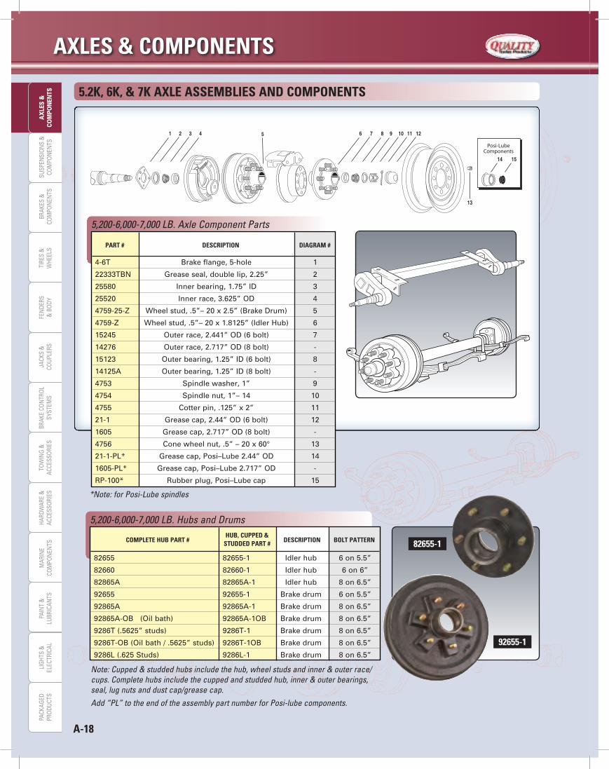
TS 5.2k, 6k, & 7k AXLe ASSeMBLieS ANd COMPONeNTS
*Note: for Posi-Lube spindles
5,200-6,000-7,000 LB. Axle Component Parts
PArT # deSCriPTiON diAgrAM #
4-6T Brake flange, 5-hole 1
22333TBN Grease seal, double lip, 2.25” 2
25580 Inner bearing, 1.75” ID 3
25520 Inner race, 3.625” OD 4
4759-25-Z Wheel stud, .5”– 20 x 2.5” (Brake Drum) 5
4759-Z Wheel stud, .5”– 20 x 1.8125” (Idler Hub) 6
15245 Outer race, 2.441” OD (6 bolt) 7
14276 Outer race, 2.717” OD (8 bolt) -
15123 Outer bearing, 1.25” ID (6 bolt) 8
14125A Outer bearing, 1.25” ID (8 bolt) -
4753 Spindle washer, 1” 9
4754 Spindle nut, 1”– 14 10
4755 Cotter pin, .125” x 2” 11
21-1 Grease cap, 2.44” OD (6 bolt) 12
1605 Grease cap, 2.717” OD (8 bolt) -
4756 Cone wheel nut, .5” – 20 x 60° 13
21-1-PL* Grease cap, Posi–Lube 2.44” OD 14
1605-PL* Grease cap, Posi–Lube 2.717” OD -
RP-100* Rubber plug, Posi–Lube cap 15
Note: Cupped & studded hubs include the hub, wheel studs and inner & outer race/cups. Complete hubs include the cupped and studded hub, inner & outer bearings, seal, lug nuts and dust cap/grease cap.
Add “PL” to the end of the assembly part number for Posi-lube components.
5,200-6,000-7,000 LB. Hubs and Drums
COMPLeTe HuB PArT # HuB, CuPPed &
deSCriPTiON BOLT PATTerN STudded PArT #
82655 82655-1 Idler hub 6 on 5.5”
82660 82660-1 Idler hub 6 on 6”
82865A 82865A-1 Idler hub 8 on 6.5”
92655 92655-1 Brake drum 6 on 5.5”
92865A 92865A-1 Brake drum 8 on 6.5”
92865A-OB (Oil bath) 92865A-1OB Brake drum 8 on 6.5”
9286T (.5625” studs) 9286T-1 Brake drum 8 on 6.5”
9286T-OB (Oil bath / .5625” studs) 9286T-1OB Brake drum 8 on 6.5”
9286L (.625 Studs) 9286L-1 Brake drum 8 on 6.5”
82655-1
92655-1
A-19
AXLeS & COMPONeNTSLIG
HTS &
ELECTRICALPAIN
T &LU
BRICANTS
MARIN
ECO
MPO
NEN
TSHARDW
ARE &ACCESSO
RIESTO
WIN
G &
ACCESSORIES
JACKS &CO
UPLERS
BRAKES &CO
MPO
NEN
TSBRAKE CO
NTRO
LSYSTEM
SSU
SPENSIO
NS &
COM
PON
ENTS
TIRES &W
HEELSFEN
DERS&
BODY
AX
LES &CO
MPO
NEN
TSPACKAG
EDPRO
DUCTS
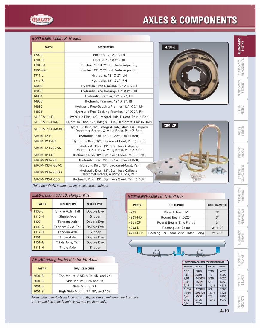
Note: See Brake section for more disc brake options.
5,200-6,000-7,000 LB. Brakes
PArT # deSCriPTiON
4704-L Electric, 12” X 2”, LH
4704-R Electric, 12” X 2”, RH
4704-LA Electric, 12” X 2”, LH, Auto Adjusting
4704-RA Electric, 12” X 2”, RH, Auto Adjusting
4711-L Hydraulic, 12” X 2”, LH
4711-R Hydraulic, 12” X 2”, RH
42029 Hydraulic Free-Backing, 12” X 2”, LH
42028 Hydraulic Free-Backing, 12” X 2”, RH
44984 Hydraulic Premier, 12” X 2”, LH
44983 Hydraulic Premier, 12” X 2”, RH
44896 Hydraulic Free-Backing Premier, 12” X 2”, LH
44895 Hydraulic Free-Backing Premier, 12” X 2”, RH
2/HRCM-12-E Hydraulic Disc, 12”, Integral Hub, E-Coat, Pair (6 Bolt)
2/HRCM-12-DAC Hydraulic Disc, 12”, Integral Hub, Dacromet, Pair (6 Bolt)
2/HRCM-12-DAC-SS Hydraulic Disc, 12”, Integral Hub, Stainless Calipers,
Dacromet Rotors, & Mntg Brkts, Pair (6 Bolt)
2/RCM-12-E Hydraulic Disc, 12”, E-Coat, Pair (6 Bolt)
2/RCM-12-DAC Hydraulic Disc, 12”, Dacromet-Coat, Pair (6 Bolt)
2/RCM-12-DAC-SS Hydraulic Disc, 12”, Stainless Calipers, Dacromet Rotors, & Mntg Brkts, Pair (6 Bolt)
2/RCM-12-SS Hydraulic Disc, 12”, Stainless Steel, Pair (6 Bolt)
2/RCM-133-7-8E Hydraulic Disc, 13”, E-Coat, Pair (8 Bolt)
2/RCM-133-7-8DAC Hydraulic Disc, 13”, Dacromet-Coat, Pair
2/RCM-133-7-8DSS Hydraulic Disc, 13”, Stainless Calipers, Dacromet Rotors, & Mntg Brkts, Pair
2/RCM-133-7-8SS Hydraulic Disc, 13”, Stainless Steel, Pair (8 Bolt)
PArT # deSCriPTiON SPriNg TyPe
5,200-6,000-7,000 LB. Hanger Kits
4103-L Single Axle, Tall Double Eye
4115-H Single Axle Slipper
4102 Tandem Axle Double Eye
4102-A Tandem Axle, Tall Double Eye
4114-H Tandem Axle Slipper
4101 Triple Axle Double Eye
4101-A Triple Axle, Tall Double Eye
4113-H Triple Axle Slipper
Note: Side mount kits include nuts, bolts, washers, and mounting brackets.Top mount kits include nuts, bolts and washers only.
PArT # TOP/Side MOuNT
AP (Attaching Parts) Kits for EQ Axles
3501-B Top Mount (3.5K, 5.2K, 6K, and 7K)
6001-S Side Mount (5.2K and 6K)
7001-S Side Mount (7K)
8001-S High Side Mount (7K, 8K, and 10K)
PArT # deSCriPTiON TuBe diAMeTer
5,200-6,000-7,000 LB. U-Bolt Kits
4201 Round Beam .5” 3”
4201-HD Round Beam .5625” 3”
4201-ZP Round Beam, Zinc Plated 3”
4203-L Rectangular Beam 2” x 3”
4203-LZP Rectangular Beam, Zinc Plated, Long 2” x 3”
4704-L
4201-zP
FrACTiON TO deCiMAL CONverSiON CHArT
1/16 .06251/8 .12509/64 .1406255/32 .156253/16 .187511/64 .17187513/64 .2031251/4 .25005/16 .31253/8 .3750
FrACTiON deCiMAL FrACTiON deCiMAL
7/16 .43751/2 .50009/16 .56255/8 .625011/16 .68753/4 .750013/16 .81257/8 .875015/16 .9375
AXLeS & COMPONeNTS
A-20
SUSP
ENSI
ON
S &
COM
PON
ENTS
BRAK
ES &
COM
PON
ENTS
TIRE
S &
WHE
ELS
FEN
DERS
& B
ODY
JACK
S &
COU
PLER
STO
WIN
G &
ACCE
SSO
RIES
PAIN
T &
LUBR
ICAN
TSBR
AKE
CON
TRO
LSY
STEM
SLI
GHT
S &
ELEC
TRIC
ALM
ARIN
ECO
MPO
NEN
TSHA
RDW
ARE
&AC
CESS
ORI
ESPA
CKAG
EDPR
ODU
CTS
AX
LES
&CO
MPO
NEN
TS
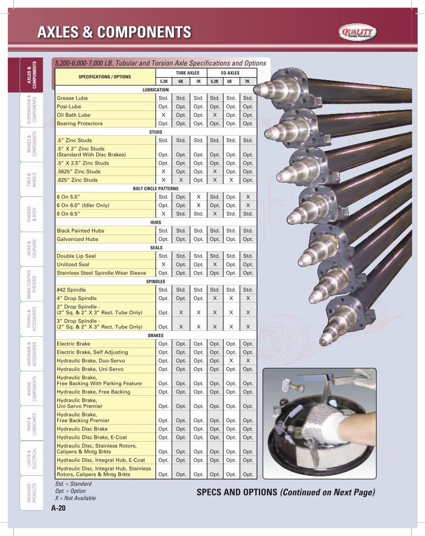
SPeCiFiCATiONS / OPTiONS TuBe AXLeS eq AXLeS
5.2k 6k 7k 5.2k 6k 7k
5,200-6,000-7,000 LB. Tubular and Torsion Axle Specifications and Options
Std. = StandardOpt. = OptionX = Not Available
SPeCS ANd OPTiONS (Continued on Next Page)
LuBriCATiON
Grease Lube Std. Std. Std. Std. Std. Std.
Posi-Lube Opt. Opt. Opt. Opt. Opt. Opt.
Oil Bath Lube X Opt. Opt. X Opt. Opt.
Bearing Protectors Opt. Opt. Opt. Opt. Opt. Opt.
STudS
.5” Zinc Studs Std. Std. Std. Std. Std. Std.
.5” X 2” Zinc Studs(Standard With Disc Brakes) Opt. Opt. Opt. Opt. Opt. Opt.
.5” X 2.5” Zinc Studs Opt. Opt. Opt. Opt. Opt. Opt.
.5625” Zinc Studs X Opt. Opt. X Opt. Opt.
.625” Zinc Studs X X Opt. X X Opt.
BOLT CirCLe PATTerNS
6 On 5.5” Std. Opt. X Std. Opt. X
6 On 6.0” (Idler Only) Opt. Opt. X Opt. Opt. X
8 On 6.5” X Std. Std. X Std. Std.
HuBS
Black Painted Hubs Std. Std. Std. Std. Std. Std.
Galvanized Hubs Opt. Opt. Opt. Opt. Opt. Opt.
SeALS
Double Lip Seal Std. Std. Std. Std. Std. Std.
Unitized Seal X Opt. Opt. X Opt. Opt.
Stainless Steel Spindle Wear Sleeve Opt. Opt. Opt. Opt. Opt. Opt.
SPiNdLeS
#42 Spindle Std. Std. Std. Std. Std. Std.
4” Drop Spindle Opt. Opt. Opt. X X X
2” Drop Spindle -(2” Sq. & 2” X 3” Rect. Tube Only) Opt. X X X X X
3” Drop Spindle -(2” Sq. & 2” X 3” Rect. Tube Only) Opt. X X X X X
BrAkeS
Electric Brake Opt. Opt. Opt. Opt. Opt. Opt.
Electric Brake, Self Adjusting Opt. Opt. Opt. Opt. Opt. Opt.
Hydraulic Brake, Duo-Servo Opt. Opt. Opt. Opt. X X
Hydraulic Brake, Uni-Servo Opt. Opt. Opt. Opt. Opt. Opt.
Hydraulic Brake,Free Backing With Parking Feature Opt. Opt. Opt. Opt. Opt. Opt.
Hydraulic Brake, Free Backing Opt. Opt. Opt. Opt. Opt. Opt.
Hydraulic Brake,Uni-Servo Premier Opt. Opt. Opt. Opt. Opt. Opt.
Hydraulic Brake,Free Backing Premier Opt. Opt. Opt. Opt. Opt. Opt.
Hydraulic Disc Brake Opt. Opt. Opt. Opt. Opt. Opt.
Hydraulic Disc Brake, E-Coat Opt. Opt. Opt. Opt. Opt. Opt.
Hydraulic Disc, Stainless Rotors,Calipers & Mntg Brkts Opt. Opt. Opt. Opt. Opt. Opt.
Hydraulic Disc, Integral Hub, E-Coat Opt. Opt. Opt. Opt. Opt. Opt.
Hydraulic Disc, Integral Hub, StainlessRotors, Calipers & Mntg Brkts Opt. Opt. Opt. Opt. Opt. Opt.

A-21
AXLeS & COMPONeNTSLIG
HTS &
ELECTRICALPAIN
T &LU
BRICANTS
MARIN
ECO
MPO
NEN
TSHARDW
ARE &ACCESSO
RIESTO
WIN
G &
ACCESSORIES
JACKS &CO
UPLERS
BRAKES &CO
MPO
NEN
TSBRAKE CO
NTRO
LSYSTEM
SSU
SPENSIO
NS &
COM
PON
ENTS
TIRES &W
HEELSFEN
DERS&
BODY
AX
LES &CO
MPO
NEN
TSPACKAG
EDPRO
DUCTS
PArT # STyLe LeNgTh CAPACiTy (eA) NO. Of LeAveS WidTh
Common Leaf Springs for 5,200-6,000-7,000 LB. Axles
Note: For additional spring options see pages B-6 Thru B-8.
4352-29 Double Eye 25.25” 2,900 lbs. 5 1.75”
4342-30 Double Eye 26” 3,000 lbs. 4 1.75”
4362-30 Double Eye 27” 3,000 lbs. 6 1.75”
4382-30 Double Eye 26” 3,000 lbs. 8 1.75”
4362-33 Double Eye 25.25” 3,300 lbs. 6 1.75”
1003T3 Slipper 26.125” 2,500 lbs. 4 2”
4351-30 Slipper 27” 3,000 lbs. 5 2”
1203T3 Slipper 26.125” 3,500 lbs. 5 2”
SPeCS ANd OPTiONS (Continued)
SPeCifiCATiONS / OPTiONS Tube AXLeS eQ AXLeS
5.2K 6K 7K 5.2K 6K 7K
5,200-6,000-7,000 LB. Tubular and Torsion Axle Specifications and Options
brAKeS (CONTiNued)
Abs Sensors (8 Bolt Disc Only) X Opt. Opt. X Opt. Opt.
Brake Flange On Idler Axle Std. Std. Std. Std. Std. Std.
Pre-Wired Axle Tubing Opt. Opt. Opt. Opt. Opt. Opt.
Brake Wire Protectors Opt. Opt. Opt. Opt. Opt. Opt.
Long Magnet Lead Wires Opt. Opt. Opt. Opt. Opt. Opt.
AXLe MATeriALS
3” X High Strength Round Tube Std. Std. X X X X
3” X High Strength Hd Round Tube X Opt. Std. X X X
2” X 3” Rectangular Tube Opt. X X X X X
3.031” Round Corner Square Tube X X X Std. Std. X
3.50” Round Corner Square Tube X X X X X Std.
Cambered Axle Tubing Opt. Opt. Opt. Std. Std. Std.
V-Bend Tubing X X X Opt. Opt. Opt.
Galvanized Axle Beam Opt. Opt. Opt. Opt. Opt. Opt.
eQ ATTAChiNg brACKeTS
High Mount Brackets +.5” X X X Opt. Opt. Opt.
Std. = StandardOpt. = OptionX = Not Available
1003T3
frACTiON TO deCiMAL CONverSiON ChArT
1/16 .06251/8 .12509/64 .1406255/32 .156253/16 .187511/64 .17187513/64 .2031251/4 .25005/16 .31253/8 .3750
frACTiON deCiMAL frACTiON deCiMAL
7/16 .43751/2 .50009/16 .56255/8 .625011/16 .68753/4 .750013/16 .81257/8 .875015/16 .9375

AXLeS & COMPONeNTS
A-22
SUSP
ENSI
ON
S &
COM
PON
ENTS
BRAK
ES &
COM
PON
ENTS
TIRE
S &
WHE
ELS
FEN
DERS
& B
ODY
JACK
S &
COU
PLER
STO
WIN
G &
ACCE
SSO
RIES
PAIN
T &
LUBR
ICAN
TSBR
AKE
CON
TRO
LSY
STEM
SLI
GHT
S &
ELEC
TRIC
ALM
ARIN
ECO
MPO
NEN
TSHA
RDW
ARE
&AC
CESS
ORI
ESPA
CKAG
EDPR
ODU
CTS
AX
LES
&CO
MPO
NEN
TS 8K AXLe ASSeMbLieS ANd COMPONeNTS
*Note: For Posi-Lube Spindles
8,000 LB. Axle Component Parts
PArT # deSCriPTiON diAgrAM #
370219A Oil seal, unitized, 2.25” 2
22333TBN Grease seal, double lip, 2.25” Opt.
25580 Inner bearing, 1.75” ID 3
25520 Inner race, 3.625” OD 4
4759-27 Wheel stud, .5625”- 18 x 3” 5
4738-28 Wheel stud, .625”- 18 x 3.25” -
02420 Outer race, 2.688” OD 6
02475 Outer bearing, 1.25” ID 7
4753 Spindle washer, 1” 8
4754-12 Spindle nut, 1”- 14 9
4755 Cotter pin, .125” x 2” 10
8001 Oil cap, complete assembly 11
10-45 “O” ring 11A
RP-200 Oil cap plug 11B
1605-PL* Grease cap, Posi–Lube 2.717” OD 12
RP-100* Rubber plug, Posi–Lube cap 13
4756-1 Cone wheel nut, .5625” - 18 x 60° 14
4756-2 Cone wheel nut, .5625” - 18 x 90° Opt.
X1048 Cone wheel nut, .625” - 18 x 90° Opt.
568216 Swivel Flange Nut, .625“ - 18 Opt.
Note: Cupped & studded hubs include the hub, wheel studs and inner & outer race/cups. Complete hubs include the cupped and studded hub, inner & outer bearings, seal, lug nuts and dust cap/grease cap.
8,000 LB. Hubs and Drums COMPLeTe
hub, CuPPed & deSCriPTiON bOLT PATTerN hub PArT # STudded PArT #
80865 80865-1 Idler Hub 8 on 6.5” - .5625” - Studs
90865 90865-1 Brake Drum 8 on 6.5” - .5625” - Studs
9086L 9086L-1 Brake Drum 8 on 6.5” - .625” - Studs
90865-GP 90865-1GP Brake Drum, Grease 8 on 6.5” - .5625” - Studs
9086L-G 9086L-1G Brake Drum, Grease 8 on 6.5” - .625” - Studs
A-23
AXLeS & COMPONeNTSLIG
HTS &
ELECTRICALPAIN
T &LU
BRICANTS
MARIN
ECO
MPO
NEN
TSHARDW
ARE &ACCESSO
RIESTO
WIN
G &
ACCESSORIES
JACKS &CO
UPLERS
BRAKES &CO
MPO
NEN
TSBRAKE CO
NTRO
LSYSTEM
SSU
SPENSIO
NS &
COM
PON
ENTS
TIRES &W
HEELSFEN
DERS&
BODY
AX
LES &CO
MPO
NEN
TSPACKAG
EDPRO
DUCTS
8,000 LB. Brakes
PArT # deSCriPTiON
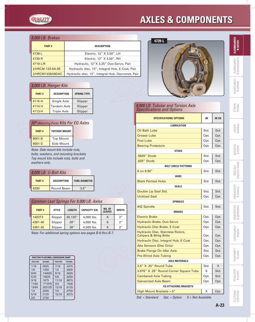
4739-L Electric, 12” X 3.50”, LH
4739-R Electric, 12” X 3.50”, RH
4719-L/R Hydraulic, 12”X 3.25” Duo-Servo, Pair
2/HRCM-133-8A-9E Hydraulic disc, 13”, Integral Hub, E-Coat, Pair
2/HRCM1338A9DAC Hydraulic disc, 13”, Integral Hub, Dacromet, Pair
8,000 LB. Hanger Kits
PArT # deSCriPTiON SPriNg TyPe
4115-H Single Axle Slipper
4114-H Tandem Axle Slipper
4113-H Triple Axle Slipper
Note: Side mount kits include nuts, bolts, washers, and mounting brackets.Top mount kits include nuts, bolts and washers only.
AP (Attaching Parts) Kits For EQ Axles
PArT # TOP/Side MOuNT
8001-B Top Mount
8001-S Side Mount
8,000 LB. U-Bolt Kits
PArT # deSCriPTiON TuBe diAMeTer
4200 Round Beam 3.5”
Note: For additional spring options see pages B-6 thru B-7.
Common Leaf Springs For 8,000 LB. Axles
PArT # STyLe LeNgTH CAPACiTy (eA) NO. OF WidTH LeAveS
1403T3 Slipper 26.125” 4,000 lbs. 6 2”
4361-40 Slipper 29” 4,000 lbs. 6 2”
4361-45 Slipper 30” 4,500 lbs. 6 2”
8,000 LB. Tubular and Torsion Axle Specifications and Options
Std. = Standard Opt. = Option X = Not Available
SPeCiFiCATiONS/ OPTiONS 8k 8k eq
LuBriCATiON
Oil Bath Lube Std. Std.
Grease Lube Opt. Opt.
Posi-Lube Opt. Opt.
Bearing Protectors Opt. Opt.
STudS
.5625” Studs Std. Std.
.625” Studs Opt. Opt.
BOLT CirCLe PATTerNS
8 on 6.50” Std. Std.
HuBS
Black Painted Hubs Std. Std.
SeALS
Double Lip Seal Std. Std. Std.
Unitized Seal Opt. Opt.
SPiNdLeS
#42 Spindle Std. Std.
BrAkeS
Electric Brake Opt. Opt.
Hydraulic Brake, Duo-Servo Opt. Opt.
Hydraulic Disc Brake, E-Coat Opt. Opt.
Hydraulic Disc, Stainless Rotors,Calipers & Mntg Brkts Opt. Opt.
Hydraulic Disc, Integral Hub, E-Coat Opt. Opt.
Abs Sensors (Disc Only) Opt. Opt.
Brake Flange On Idler Axle Std. Std.
Pre-Wired Axle Tubing Opt. Opt.
AXLe MATeriALS
3.5” X .25” Round Tube Std. X
3.875” X .25” Round Corner Square Tube X Std.
Cambered Axle Tubing Opt. Std.
Galvanized Axle Beam Opt. Opt.
eq ATTACHiNg BrACkeTS
High Mount Brackets +.5” X Opt.
FrACTiON TO deCiMAL CONverSiON CHArT
1/16 .06251/8 .12509/64 .1406255/32 .156253/16 .187511/64 .17187513/64 .2031251/4 .25005/16 .31253/8 .3750
FrACTiON deCiMAL FrACTiON deCiMAL
7/16 .43751/2 .50009/16 .56255/8 .625011/16 .68753/4 .750013/16 .81257/8 .875015/16 .9375
4739-L

AXLeS & COMPONeNTS
A-24
SUSP
ENSI
ON
S &
COM
PON
ENTS
BRAK
ES &
COM
PON
ENTS
TIRE
S &
WHE
ELS
FEN
DERS
& B
ODY
JACK
S &
COU
PLER
STO
WIN
G &
ACCE
SSO
RIES
PAIN
T &
LUBR
ICAN
TSBR
AKE
CON
TRO
LSY
STEM
SLI
GHT
S &
ELEC
TRIC
ALM
ARIN
ECO
MPO
NEN
TSHA
RDW
ARE
&AC
CESS
ORI
ESPA
CKAG
EDPR
ODU
CTS
AX
LES
&CO
MPO
NEN
TS 10k LB. AXLe ASSeMBLieS ANd COMPONeNTS
10,000 LB. Axle Component Parts
PArT # deSCriPTiON diAgrAM #
Notes:1. Swivel Flange Lug Nuts to be torqued to 130-170 FT. LBS.2. Spindle nuts torqued to 100 FT. LBS. then backed off 1/4 turn.3. U-Bolts nuts to be torqued to 130-170 FT. LBS.4. Brake attaching bolts to be torqued to 70-100 FT. LBS.5. Oil / Grease cap to be torqued to 20-30 FT. LBS.
RP-200 Oil Cap Plug 12C
12011 Oil Cap 12B
1201G Grease Cap 12B
V75340 O-Ring 12A
12011-1 Oil Cap, Complete Assembly 12
CP-3 Cotter Pin 11
4797 Spindle Nut 10
4798 Spindle Washer 9
25580 Outer Bearing 8
25520 Outer Race 7
99865-1P475A Drum, 4.75” Pilot (w/ Armature Plate) 14
99865-1PA Drum, 4.88” Pilot (w/ Armature Plate) 14
568216 Swivel Flange Nut, .625 -18 6
4738-28 Stud, .625 -18 5
28521 Inner Race 3
28580 Inner Bearing 2
CR27438 Oil Seal 1
OB27377 Grease Seal -
14LN Armature Plate Nut 4B
10KARM Armature Plate 4
FL14201 Armature Plate Screw 4A
4738-L Electric Brake, 12.25” X 3.5” L -
4738-R Electric Brake, 12.25” X 3.5” R -
12LN Brake Attaching Nut -
SP-5 Spring Pad -
SP-5-ADJ Adjustable Spring Pad (Optional) -
FrACTiON deCiMAL
FRACTION TO DECIMAL CONVERSION CHART
1/16 1/8 9/64 5/32 3/16 11/64 13/64 1/4 5/16 3/8 7/16 1/2 9/16 5/8 11/16 3/4 13/16 7/8 15/16.0625 .1250 .140625 .15625 .1875 .171875 .203125 .2500 .3125 .3750 .4375 .5000 .5625 .6250 .6875 .7500 .8125 .8750 .9375
99865-1PA
A-25
AXLeS & COMPONeNTSLIG
HTS &
ELECTRICALPAIN
T &LU
BRICANTS
MARIN
ECO
MPO
NEN
TSHARDW
ARE &ACCESSO
RIESTO
WIN
G &
ACCESSORIES
JACKS &CO
UPLERS
BRAKES &CO
MPO
NEN
TSBRAKE CO
NTRO
LSYSTEM
SSU
SPENSIO
NS &
COM
PON
ENTS
TIRES &W
HEELSFEN
DERS&
BODY
AX
LES &CO
MPO
NEN
TSPACKAG
EDPRO
DUCTS
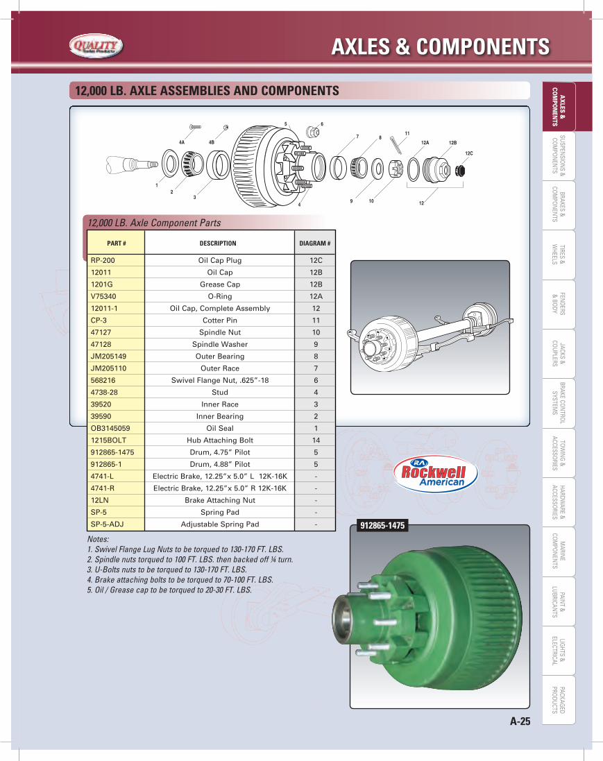
Notes:1. Swivel Flange Lug Nuts to be torqued to 130-170 FT. LBS.2. Spindle nuts torqued to 100 FT. LBS. then backed off ¼ turn.3. U-Bolts nuts to be torqued to 130-170 FT. LBS.4. Brake attaching bolts to be torqued to 70-100 FT. LBS.5. Oil / Grease cap to be torqued to 20-30 FT. LBS.
12,000 Lb. AXLe ASSeMbLieS ANd COMPONeNTS
12,000 LB. Axle Component Parts
PArT # deSCriPTiON diAgrAM #
RP-200 Oil Cap Plug 12C
12011 Oil Cap 12B
1201G Grease Cap 12B
V75340 O-Ring 12A
12011-1 Oil Cap, Complete Assembly 12
CP-3 Cotter Pin 11
47127 Spindle Nut 10
47128 Spindle Washer 9
JM205149 Outer Bearing 8
JM205110 Outer Race 7
568216 Swivel Flange Nut, .625”-18 6
4738-28 Stud 4
39520 Inner Race 3
39590 Inner Bearing 2
OB3145059 Oil Seal 1
1215BOLT Hub Attaching Bolt 14
912865-1475 Drum, 4.75” Pilot 5
912865-1 Drum, 4.88” Pilot 5
4741-L Electric Brake, 12.25”x 5.0” L 12K-16K -
4741-R Electric Brake, 12.25”x 5.0” R 12K-16K -
12LN Brake Attaching Nut -
SP-5 Spring Pad -
SP-5-ADJ Adjustable Spring Pad - 912865-1475

AXLeS & COMPONeNTS
A-26
SUSP
ENSI
ON
S &
COM
PON
ENTS
BRAK
ES &
COM
PON
ENTS
TIRE
S &
WHE
ELS
FEN
DERS
& B
ODY
JACK
S &
COU
PLER
STO
WIN
G &
ACCE
SSO
RIES
PAIN
T &
LUBR
ICAN
TSBR
AKE
CON
TRO
LSY
STEM
SLI
GHT
S &
ELEC
TRIC
ALM
ARIN
ECO
MPO
NEN
TSHA
RDW
ARE
&AC
CESS
ORI
ESPA
CKAG
EDPR
ODU
CTS
AX
LES
&CO
MPO
NEN
TS
16,000 LB. AXLe ASSeMBLieS ANd COMPONeNTS
Art work to be supplied by QRG
Notes:6. Swivel Flange Lug Nuts to be torqued to 450-500 FT. LBS.7. Spindle nuts torqued to 100 FT. LBS. then backed off ¼ turn.8. U-Bolts nuts to be torqued to 130-170 FT. LBS.9. Brake attaching bolts to be torqued to 70-100 FT. LBS.10. Oil / Grease cap to be torqued to 20-30 FT. LBS.
16,000 LB. AXLe ASSeMBLieS ANd COMPONeNTS
16,000 LB. Axle Component Parts
PArT # deSCriPTiON diAgrAM #
916108-1
RP-200 Oil Cap Plug 12C
12011 Oil Cap 12B
V75340 O-Ring 12A
12011-1 Oil Cap, Complete Assembly 12
CP-3 Cotter Pin 11
47127 Spindle Nut 10
47128 Spindle Washer 9
JM205149 Outer Bearing 8
JM205110 Outer Race 7
39520 Inner Race 3
39590 Inner Bearing 2
OB3145059 Oil Seal 1
1215BOLT Hub Attaching Bolt 4
4741-L Electric Brake, 12.25”x 5.0” LH 12K -16K -
4741-R Electric Brake, 12.25”x 5.0” RH 12K -16K -
12LN Brake Attaching Nut -
SP-5 Spring Pad -
SP-5-ADJ Adjustable Spring Pad -
druMS
916108-1 Brake Drum, 10 on 8.75” Bolt Pattern 5
09065114 Swivel Flange Nut, .75 -16 6
4741-10 Stud Ring 14
4741-34 Stud 15
916810-1 Brake Drum, 8 on 275mm Bolt Pattern -
WN33 Swivel Flange Nut, m22-1.5 x 31 -
4741-30 Stud -
FrACTiON deCiMAL
FRACTION TO DECIMAL CONVERSION CHART
1/16 1/8 9/64 5/32 3/16 11/64 13/64 1/4 5/16 3/8 7/16 1/2 9/16 5/8 11/16 3/4 13/16 7/8 15/16.0625 .1250 .140625 .15625 .1875 .171875 .203125 .2500 .3125 .3750 .4375 .5000 .5625 .6250 .6875 .7500 .8125 .8750 .9375
A-27
AXLeS & COMPONeNTSLIG
HTS &
ELECTRICALPAIN
T &LU
BRICANTS
MARIN
ECO
MPO
NEN
TSHARDW
ARE &ACCESSO
RIESTO
WIN
G &
ACCESSORIES
JACKS &CO
UPLERS
BRAKES &CO
MPO
NEN
TSBRAKE CO
NTRO
LSYSTEM
SSU
SPENSIO
NS &
COM
PON
ENTS
TIRES &W
HEELSFEN
DERS&
BODY
AX
LES &CO
MPO
NEN
TSPACKAG
EDPRO
DUCTS
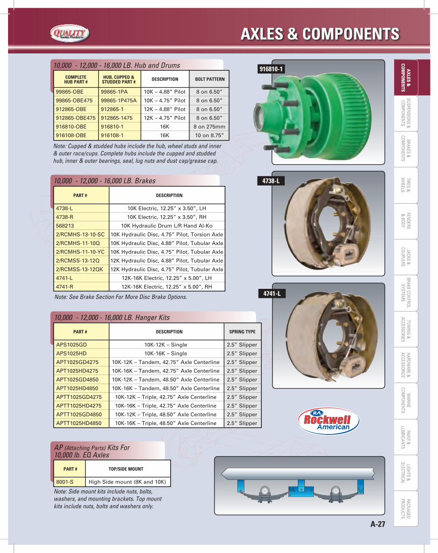
Note: Cupped & studded hubs include the hub, wheel studs and inner & outer race/cups. Complete hubs include the cupped and studded hub, inner & outer bearings, seal, lug nuts and dust cap/grease cap.
COMPLeTe hub, CuPPed &
deSCriPTiON bOLT PATTerN hub PArT # STudded PArT #
99865-OBE 99865-1PA 10K – 4.88” Pilot 8 on 6.50”
99865-OBE475 99865-1P475A 10K – 4.75” Pilot 8 on 6.50”
912865-OBE 912865-1 12K – 4.88” Pilot 8 on 6.50”
912865-OBE475 912865-1475 12K – 4.75” Pilot 8 on 6.50”
916810-OBE 916810-1 16K 8 on 275mm
916108-OBE 916108-1 16K 10 on 8.75”
10,000 - 12,000 - 16,000 LB. Hub and Drums 916810-1
4738-L
4741-LNote: See Brake Section For More Disc Brake Options.
PArT # deSCriPTiON
4738-L 10K Electric, 12.25” x 3.50”, LH
4738-R 10K Electric, 12.25” x 3.50”, RH
568213 10K Hydraulic Drum L/R Hand Al-Ko
2/RCMHS-13-10-SC 10K Hydraulic Disc, 4.75” Pilot, Torsion Axle
2/RCMHS-11-10Q 10K Hydraulic Disc, 4.88” Pilot, Tubular Axle
2/RCMHS-11-10-YC 10K Hydraulic Disc, 4.75” Pilot, Tubular Axle
2/RCMSS-13-12Q 12K Hydraulic Disc, 4.88” Pilot, Tubular Axle
2/RCMSS-13-12QK 12K Hydraulic Disc, 4.75” Pilot, Tubular Axle
4741-L 12K-16K Electric, 12.25” x 5.00”, LH
4741-R 12K-16K Electric, 12.25” x 5.00”, RH
10,000 - 12,000 - 16,000 LB. Brakes
PArT # deSCriPTiON SPriNg TyPe
APS1025GD 10K-12K – Single 2.5” Slipper
APS1025HD 10K-16K – Single 2.5” Slipper
APT1025GD4275 10K-12K – Tandem, 42.75” Axle Centerline 2.5” Slipper
APT1025HD4275 10K-16K – Tandem, 42.75” Axle Centerline 2.5” Slipper
APT1025GD4850 10K-12K – Tandem, 48.50” Axle Centerline 2.5” Slipper
APT1025HD4850 10K-16K – Tandem, 48.50” Axle Centerline 2.5” Slipper
APTT1025GD4275 10K-12K – Triple, 42.75” Axle Centerline 2.5” Slipper
APTT1025HD4275 10K-16K – Triple, 42.75” Axle Centerline 2.5” Slipper
APTT1025GD4850 10K-12K – Triple, 48.50” Axle Centerline 2.5” Slipper
APTT1025HD4850 10K-16K – Triple, 48.50” Axle Centerline 2.5” Slipper
10,000 - 12,000 - 16,000 LB. Hanger Kits
Note: Side mount kits include nuts, bolts, washers, and mounting brackets. Top mount kits include nuts, bolts and washers only.
PArT # TOP/Side MOuNT
8001-S High Side mount (8K and 10K)
AP (Attaching Parts) Kits For 10,000 lb. EQ Axles
AXLeS & COMPONeNTS
A-28
SUSP
ENSI
ON
S &
COM
PON
ENTS
BRAK
ES &
COM
PON
ENTS
TIRE
S &
WHE
ELS
FEN
DERS
& B
ODY
JACK
S &
COU
PLER
STO
WIN
G &
ACCE
SSO
RIES
PAIN
T &
LUBR
ICAN
TSBR
AKE
CON
TRO
LSY
STEM
SLI
GHT
S &
ELEC
TRIC
ALM
ARIN
ECO
MPO
NEN
TSHA
RDW
ARE
&AC
CESS
ORI
ESPA
CKAG
EDPR
ODU
CTS
AX
LES
&CO
MPO
NEN
TS
10,000 -12,000 -16,000 LB. U-Bolt Kits
PArT # deSCriPTiON TuBe diAMeTer
APUBR50 10K - Round beam 9”X.625-11 5”
APUBR50-12K-16K 12K-16K - Round beam 10”X.75”-10 5”
PArT # STyLe LeNgTH CAPACiTy (eA) NO. OF LeAveS WidTH
Common Leaf Springs for 10,000 -12,000 -16,000 LB. Axles
Note: For additional spring options see page B-7.
43101-56 Slipper 32.25” 5,000 Lbs. 5 2.5”
4361-60 Slipper 32.25” 6,000 Lbs. 6 2.5”
093182-14 Slipper 32.50” 8,000 Lbs. 6 2.5”
Std. = Standard Opt. = Option X = Not Available
10,000 -12,000 -16,000 LB. Tubular and Torsion Axle Specifications and Options
SPeCiFiCATiONS / OPTiONS TuBe AXLeS eq AXLeS
10k 12k 16k 10k
LuBriCATiON
Oil Bath Lube Std. Std. Std. Std.
Grease Lube Opt. X X Opt.
STudS
.625” Zinc studs Std. Std. X Std.
.75” Zinc studs X. X Opt. X
.975” XM22X1.5” Zinc studs X X Opt. X
BOLT CirCLe PATTerNS
8 on 6.50” Std. Std. X Std.
10 on 8.75” X X Opt. X
8 on 275mm X X Opt. X
HuBS
4.88” Pilot - Blue Opt. X X Opt.
4.75” Pilot - Grey Opt. X X Opt.
4.88” Pilot - Green X Opt. X X
4.75” Pilot - Grey X Opt. X X
8.75” Pilot - Green X X Opt. X
275 mm Pilot - Green X X Opt. X
SeALS
Unitized Seal Std. Std. Std. Std.
Grease Seal Opt. X X Opt.
BrAkeS
Electric Brake, Self Adjusting Opt. Opt. Opt. Opt.
Hydraulic Drum Brake, Duo-Servo Opt. X X Opt.
Hydraulic Disc Brake, E-Coat Opt. X X X
Hydraulic Disc Brake, Dacromet Coat Opt. Opt. X Opt.
ABS Sensors (Disc Only) Opt. Opt. X Opt.
AXLe MATeriALS
5” Round tube Std. Std. Std. X
3.875” Round Corner Square Tube X X X Std.
eq ATTACHiNg BrACkeTS
High Mount Brackets +.5” X X X Std.
43101-56
FrACTiON TO deCiMAL CONverSiON CHArT
1/16 .06251/8 .12509/64 .1406255/32 .156253/16 .187511/64 .17187513/64 .2031251/4 .25005/16 .31253/8 .3750
FrACTiON deCiMAL FrACTiON deCiMAL
7/16 .43751/2 .50009/16 .56255/8 .625011/16 .68753/4 .750013/16 .81257/8 .875015/16 .9375
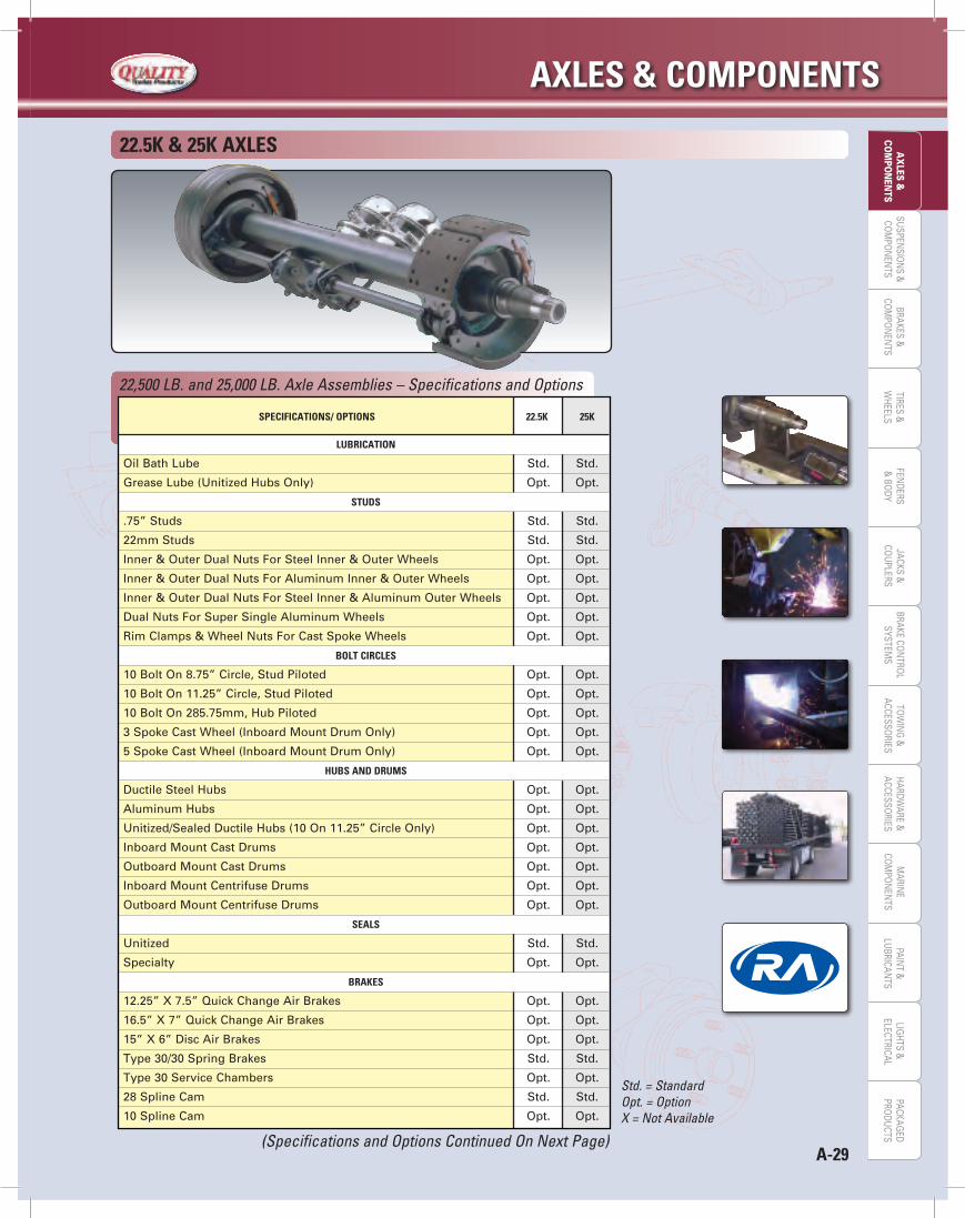
A-29
AXLeS & COMPONeNTSLIG
HTS &
ELECTRICALPAIN
T &LU
BRICANTS
MARIN
ECO
MPO
NEN
TSHARDW
ARE &ACCESSO
RIESTO
WIN
G &
ACCESSORIES
JACKS &CO
UPLERS
BRAKES &CO
MPO
NEN
TSBRAKE CO
NTRO
LSYSTEM
SSU
SPENSIO
NS &
COM
PON
ENTS
TIRES &W
HEELSFEN
DERS&
BODY
AX
LES &CO
MPO
NEN
TSPACKAG
EDPRO
DUCTS
22.5k & 25k AXLeS
Std. = Standard Opt. = Option X = Not Available
22,500 LB. and 25,000 LB. Axle Assemblies – Specifications and Options
SPeCiFiCATiONS/ OPTiONS 22.5k 25k
LuBriCATiON
Oil Bath Lube Std. Std.
Grease Lube (Unitized Hubs Only) Opt. Opt.
STudS
.75” Studs Std. Std.
22mm Studs Std. Std.
Inner & Outer Dual Nuts For Steel Inner & Outer Wheels Opt. Opt.
Inner & Outer Dual Nuts For Aluminum Inner & Outer Wheels Opt. Opt.
Inner & Outer Dual Nuts For Steel Inner & Aluminum Outer Wheels Opt. Opt.
Dual Nuts For Super Single Aluminum Wheels Opt. Opt.
Rim Clamps & Wheel Nuts For Cast Spoke Wheels Opt. Opt.
BOLT CirCLeS
10 Bolt On 8.75” Circle, Stud Piloted Opt. Opt.
10 Bolt On 11.25” Circle, Stud Piloted Opt. Opt.
10 Bolt On 285.75mm, Hub Piloted Opt. Opt.
3 Spoke Cast Wheel (Inboard Mount Drum Only) Opt. Opt.
5 Spoke Cast Wheel (Inboard Mount Drum Only) Opt. Opt.
HuBS ANd druMS
Ductile Steel Hubs Opt. Opt.
Aluminum Hubs Opt. Opt.
Unitized/Sealed Ductile Hubs (10 On 11.25” Circle Only) Opt. Opt.
Inboard Mount Cast Drums Opt. Opt.
Outboard Mount Cast Drums Opt. Opt.
Inboard Mount Centrifuse Drums Opt. Opt.
Outboard Mount Centrifuse Drums Opt. Opt.
SeALS
Unitized Std. Std.
Specialty Opt. Opt.
BrAkeS
12.25” X 7.5” Quick Change Air Brakes Opt. Opt.
16.5” X 7” Quick Change Air Brakes Opt. Opt.
15” X 6” Disc Air Brakes Opt. Opt.
Type 30/30 Spring Brakes Std. Std.
Type 30 Service Chambers Opt. Opt.
28 Spline Cam Std. Std.
10 Spline Cam Opt. Opt.
(Specifications and Options Continued On Next Page)
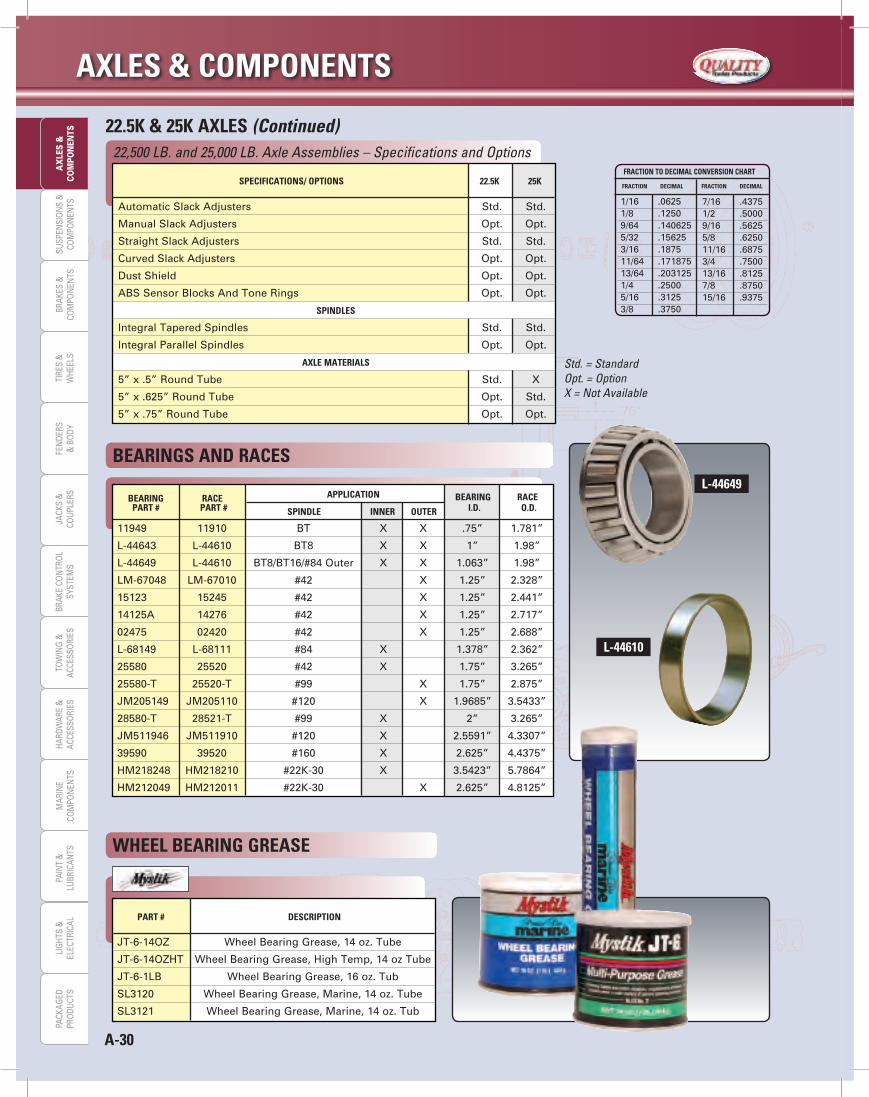
AXLeS & COMPONeNTS
A-30
SUSP
ENSI
ON
S &
COM
PON
ENTS
BRAK
ES &
COM
PON
ENTS
TIRE
S &
WHE
ELS
FEN
DERS
& B
ODY
JACK
S &
COU
PLER
STO
WIN
G &
ACCE
SSO
RIES
PAIN
T &
LUBR
ICAN
TSBR
AKE
CON
TRO
LSY
STEM
SLI
GHT
S &
ELEC
TRIC
ALM
ARIN
ECO
MPO
NEN
TSHA
RDW
ARE
&AC
CESS
ORI
ESPA
CKAG
EDPR
ODU
CTS
AX
LES
&CO
MPO
NEN
TS 22.5k & 25k AXLeS (Continued)
Std. = Standard Opt. = OptionX = Not Available
22,500 LB. and 25,000 LB. Axle Assemblies – Specifications and Options
SPeCiFiCATiONS/ OPTiONS 22.5k 25k
Automatic Slack Adjusters Std. Std.
Manual Slack Adjusters Opt. Opt.
Straight Slack Adjusters Std. Std.
Curved Slack Adjusters Opt. Opt.
Dust Shield Opt. Opt.
ABS Sensor Blocks And Tone Rings Opt. Opt.
SPiNdLeS
Integral Tapered Spindles Std. Std.
Integral Parallel Spindles Opt. Opt.
AXLe MATeriALS
5” x .5” Round Tube Std. X
5” x .625” Round Tube Opt. Std.
5” x .75” Round Tube Opt. Opt.
L-44649
L-44610
WHeeL BeAriNg greASe
FrACTiON TO deCiMAL CONverSiON CHArT
1/16 .06251/8 .12509/64 .1406255/32 .156253/16 .187511/64 .17187513/64 .2031251/4 .25005/16 .31253/8 .3750
FrACTiON deCiMAL FrACTiON deCiMAL
7/16 .43751/2 .50009/16 .56255/8 .625011/16 .68753/4 .750013/16 .81257/8 .875015/16 .9375
PArT # deSCriPTiON
JT-6-14OZ Wheel Bearing Grease, 14 oz. Tube
JT-6-14OZHT Wheel Bearing Grease, High Temp, 14 oz Tube
JT-6-1LB Wheel Bearing Grease, 16 oz. Tub
SL3120 Wheel Bearing Grease, Marine, 14 oz. Tube
SL3121 Wheel Bearing Grease, Marine, 14 oz. Tub
BeAriNg rACe APPLiCATiON BeAriNg rACe
PArT # PArT # SPiNdLe iNNer OuTer i.d. O.d.
BeAriNgS ANd rACeS
11949 11910 BT X X .75” 1.781”
L-44643 L-44610 BT8 X X 1” 1.98”
L-44649 L-44610 BT8/BT16/#84 Outer X X 1.063” 1.98”
LM-67048 LM-67010 #42 X 1.25” 2.328”
15123 15245 #42 X 1.25” 2.441”
14125A 14276 #42 X 1.25” 2.717”
02475 02420 #42 X 1.25” 2.688”
L-68149 L-68111 #84 X 1.378” 2.362”
25580 25520 #42 X 1.75” 3.265”
25580-T 25520-T #99 X 1.75” 2.875”
JM205149 JM205110 #120 X 1.9685” 3.5433”
28580-T 28521-T #99 X 2” 3.265”
JM511946 JM511910 #120 X 2.5591” 4.3307”
39590 39520 #160 X 2.625” 4.4375”
HM218248 HM218210 #22K-30 X 3.5423” 5.7864”
HM212049 HM212011 #22K-30 X 2.625” 4.8125”
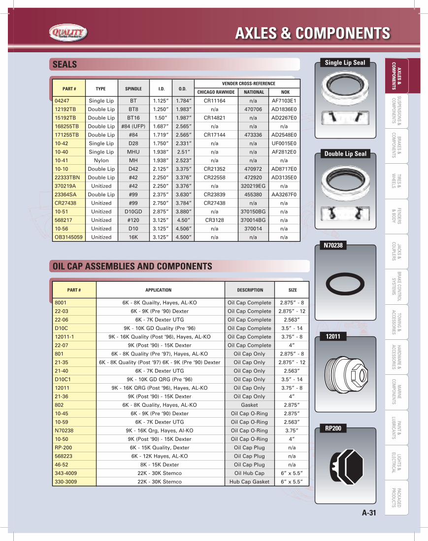
A-31
AXLeS & COMPONeNTSLIG
HTS &
ELECTRICALPAIN
T &LU
BRICANTS
MARIN
ECO
MPO
NEN
TSHARDW
ARE &ACCESSO
RIESTO
WIN
G &
ACCESSORIES
JACKS &CO
UPLERS
BRAKES &CO
MPO
NEN
TSBRAKE CO
NTRO
LSYSTEM
SSU
SPENSIO
NS &
COM
PON
ENTS
TIRES &W
HEELSFEN
DERS&
BODY
AX
LES &CO
MPO
NEN
TSPACKAG
EDPRO
DUCTS
04247 Single Lip BT 1.125” 1.784” CR11164 n/a AF7103E1
12192TB Double Lip BT8 1.250” 1.983” n/a 470706 AD1836E0
15192TB Double Lip BT16 1.50” 1.987” CR14821 n/a AD2267E0
168255TB Double Lip #84 (UFP) 1.687” 2.565” n/a n/a n/a
171255TB Double Lip #84 1.719” 2.565” CR17144 473336 AD2548E0
10-42 Single Lip D28 1.750” 2.331” n/a n/a UF0015E0
10-40 Single Lip MHU 1.938” 2.51” n/a n/a AF2812E0
10-41 Nylon MH 1.938” 2.523” n/a n/a n/a
10-10 Double Lip D42 2.125” 3.375” CR21352 470972 AD8717E0
22333TBN Double Lip #42 2.250” 3.376” CR22558 472920 AD3135E0
370219A Unitized #42 2.250” 3.376” n/a 320219EG n/a
23364SA Double Lip #99 2.375” 3.630” CR23839 455380 AA3267F0
CR27438 Unitized #99 2.750” 3.784” CR27438 n/a n/a
10-51 Unitized D10GD 2.875” 3.880” n/a 370150BG n/a
568217 Unitized #120 3.125” 4.50” CR3128 370014BG n/a
10-56 Unitized D10 3.125” 4.506” n/a 370014 n/a
OB3145059 Unitized 16K 3.125” 4.500” n/a n/a n/a
veNder CrOSS-reFereNCe PArT # TyPe SPiNdLe i.d. O.d.
CHiCAgO rAWHide NATiONAL NOk
Single Lip Seal
double Lip Seal
SeALS
PArT # APPLiCATiON deSCriPTiON Size
8001 6K - 8K Quailty, Hayes, AL-KO Oil Cap Complete 2.875” - 8
22-03 6K - 9K (Pre ‘90) Dexter Oil Cap Complete 2.875” - 12
22-06 6K - 7K Dexter UTG Oil Cap Complete 2.563”
D10C 9K - 10K GD Quality (Pre ‘96) Oil Cap Complete 3.5” - 14
12011-1 9K - 16K Quality (Post ‘96), Hayes, AL-KO Oil Cap Complete 3.75” - 8
22-07 9K (Post ‘90) - 15K Dexter Oil Cap Complete 4”
801 6K - 8K Quality (Pre ‘97), Hayes, AL-KO Oil Cap Only 2.875” - 8
21-35 6K - 8K Quality (Post ‘97) 6K - 9K (Pre ‘90) Dexter Oil Cap Only 2.875” - 12
21-40 6K - 7K Dexter UTG Oil Cap Only 2.563”
D10C1 9K - 10K GD QRG (Pre ‘96) Oil Cap Only 3.5” - 14
12011 9K - 16K QRG (Post ‘96), Hayes, AL-KO Oil Cap Only 3.75” - 8
21-36 9K (Post ‘90) - 15K Dexter Oil Cap Only 4”
802 6K - 8K Quality, Hayes, AL-KO Gasket 2.875”
10-45 6K - 9K (Pre ‘90) Dexter Oil Cap O-Ring 2.875”
10-59 6K - 7K Dexter UTG Oil Cap O-Ring 2.563”
N70238 9K - 16K Qrg, Hayes, Al-KO Oil Cap O-Ring 3.75”
10-50 9K (Post ‘90) - 15K Dexter Oil Cap O-Ring 4”
RP-200 6K - 15K Quality, Dexter Oil Cap Plug n/a
568223 6K - 12K Hayes, AL-KO Oil Cap Plug n/a
46-52 8K - 15K Dexter Oil Cap Plug n/a
343-4009 22K - 30K Stemco Oil Hub Cap 6” x 5.5”
330-3009 22K - 30K Stemco Hub Cap Gasket 6” x 5.5”
OiL CAP ASSeMBLieS ANd COMPONeNTS
N70238
rP200
12011
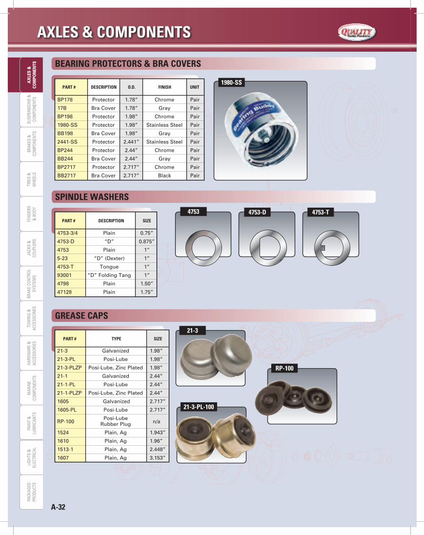
AXLeS & COMPONeNTS
A-32
SUSP
ENSI
ON
S &
COM
PON
ENTS
BRAK
ES &
COM
PON
ENTS
TIRE
S &
WHE
ELS
FEN
DERS
& B
ODY
JACK
S &
COU
PLER
STO
WIN
G &
ACCE
SSO
RIES
PAIN
T &
LUBR
ICAN
TSBR
AKE
CON
TRO
LSY
STEM
SLI
GHT
S &
ELEC
TRIC
ALM
ARIN
ECO
MPO
NEN
TSHA
RDW
ARE
&AC
CESS
ORI
ESPA
CKAG
EDPR
ODU
CTS
AX
LES
&CO
MPO
NEN
TS
PArT # deSCriPTiON Size
4753-3/4 Plain 0.75”
4753-D “D” 0.875”
4753 Plain 1”
5-23 “D” (Dexter) 1”
4753-T Tongue 1”
93001 “D” Folding Tang 1”
4798 Plain 1.50”
47128 Plain 1.75”
SPiNdLe WASHerS
PArT # TyPe Size
21-3 Galvanized 1.98”
21-3-PL Posi-Lube 1.98”
21-3-PLZP Posi-Lube, Zinc Plated 1.98”
21-1 Galvanized 2.44”
21-1-PL Posi-Lube 2.44”
21-1-PLZP Posi-Lube, Zinc Plated 2.44”
1605 Galvanized 2.717”
1605-PL Posi-Lube 2.717”
RP-100 Posi-Lube
n/a Rubber Plug
1524 Plain, Ag 1.943”
1610 Plain, Ag 1.96”
1513-1 Plain, Ag 2.448”
1607 Plain, Ag 3.153”
greASe CAPS
PArT # deSCriPTiON O.d. FiNiSH uNiT
BP178 Protector 1.78” Chrome Pair
17B Bra Cover 1.78” Gray Pair
BP198 Protector 1.98” Chrome Pair
1980-SS Protector 1.98” Stainless Steel Pair
BB198 Bra Cover 1.98” Gray Pair
2441-SS Protector 2.441” Stainless Steel Pair
BP244 Protector 2.44” Chrome Pair
BB244 Bra Cover 2.44” Gray Pair
BP2717 Protector 2.717” Chrome Pair
BB2717 Bra Cover 2.717” Black Pair
BeAriNg PrOTeCTOrS & BrA COverS
1980-SS
4753 4753-d 4753-T
rP-100
21-3
21-3-PL-100
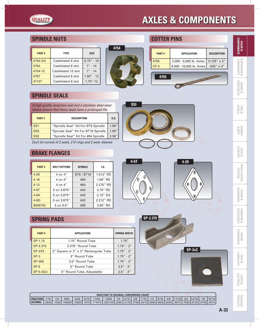
A-33
AXLeS & COMPONeNTSLIG
HTS &
ELECTRICALPAIN
T &LU
BRICANTS
MARIN
ECO
MPO
NEN
TSHARDW
ARE &ACCESSO
RIESTO
WIN
G &
ACCESSORIES
JACKS &CO
UPLERS
BRAKES &CO
MPO
NEN
TSBRAKE CO
NTRO
LSYSTEM
SSU
SPENSIO
NS &
COM
PON
ENTS
TIRES &W
HEELSFEN
DERS&
BODY
AX
LES &CO
MPO
NEN
TSPACKAG
EDPRO
DUCTS
PArT # APPLiCATiON deSCriPTiON
4755 2,000 - 8,000 lb. Axles 0.125” x 2”
CP-3 9,000 - 16,000 lb. Axles .025” x 3”
COTTer PiNS
4-29 4 on 4” BT8 / BT16 1.512” RD
4-16 4 on 4” #84 1.80” RD
4-12 4 on 4” #84 2.275” RD
4-6T 5 on 3.875” #42 2.75” RD
4-6A 5 on 3.875” #42 2.12” SQ
4-6Q 5 on 3.875” #42 2.312” RD
9045702 5 on 5.5” #99 3.95” RD
PArT # BOLT PATTerN SPiNdLe i.d.
BrAke FLANgeS
PArT # TyPe Size
4754-3/4 Castlelated 6 slot 0.75” - 16
4754 Castlelated 6 slot 1” - 14
4754-12 Castlelated 12 slot 1” - 14
4797 Castlelated 6 slot 1.50” - 12
47127 Castlelated 6 slot 1.75”-12
SPiNdLe NuTS
4755
4-6T
4754
PArT # deSCriPTiON O.d.
SS1 “Spindle Seal” Kit For BT8 Spindle 1.98”
SS5 “Spindle Seal” Kit For BT16 Spindle 1.98”
SS2 “Spindle Seal” Kit For #84 Spindle 2.56”
Each kit consist of 2 seals, 2 O-rings and 2 wear sleeves
A high quality neoprene seal and a stainless steel wear sleeve ensure that these seals have a prolonged life.
SPiNdLe SeALS
SP-1.75 1.75” Round Tube 1.75”
SP-2.375 2.375” Round Tube 1.75” - 2”
SP-2X2 2” Square or 2” x 3” Rectangular Tube 1.75” - 2”
SP-3 3” Round Tube 1.75” - 2”
SP-350 3.5” Round Tube 1.75” - 2”
SP-5 5” Round Tube 2.5” - 3”
SP-5-ADJ 5” Round Tube, Adjustable 2.5” - 3”
PArT # APPLiCATiON SPriNg WidTH
SPriNg PAdS SP-2.375
SP-2x2
4-29
FrACTiON deCiMAL
FRACTION TO DECIMAL CONVERSION CHART
1/16 1/8 9/64 5/32 3/16 11/64 13/64 1/4 5/16 3/8 7/16 1/2 9/16 5/8 11/16 3/4 13/16 7/8 15/16.0625 .1250 .140625 .15625 .1875 .171875 .203125 .2500 .3125 .3750 .4375 .5000 .5625 .6250 .6875 .7500 .8125 .8750 .9375
SSi
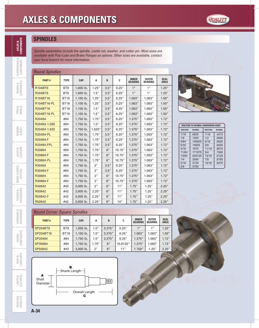
AXLeS & COMPONeNTS
A-34
SUSP
ENSI
ON
S &
COM
PON
ENTS
BRAK
ES &
COM
PON
ENTS
TIRE
S &
WHE
ELS
FEN
DERS
& B
ODY
JACK
S &
COU
PLER
STO
WIN
G &
ACCE
SSO
RIES
PAIN
T &
LUBR
ICAN
TSBR
AKE
CON
TRO
LSY
STEM
SLI
GHT
S &
ELEC
TRIC
ALM
ARIN
ECO
MPO
NEN
TSHA
RDW
ARE
&AC
CESS
ORI
ESPA
CKAG
EDPR
ODU
CTS
AX
LES
&CO
MPO
NEN
TS
Round Spindles
R104BT8 BT8 1,000 lb. 1.25” 3.5” 8.25” 1” 1” 1.25”
R204BT8 BT8 1,000 lb. 1.5” 3.5” 8.25” 1” 1” 1.25”
R104BT16 BT16 1,100 lb. 1.25” 3.5” 8.25” 1.063” 1.063” 1.50”
R104BT16-PL BT16 1,100 lb. 1.25” 3.5” 8.25” 1.063” 1.063” 1.50”
R204BT16 BT16 1,100 lb. 1.5” 3.5” 8.25” 1.063” 1.063” 1.50”
R204BT16-PL BT16 1,100 lb. 1.5” 3.5” 8.25” 1.063” 1.063” 1.50”
R20484 #84 1,750 lb. 1.75” 3.5” 8.25” 1.375” 1.063” 1.72”
R20484-1.500 #84 1,750 lb. 1.5” 3.5” 8.25” 1.375” 1.063” 1.72”
R20484-1.625 #84 1,750 lb. 1.625” 3.5” 8.25” 1.375” 1.063” 1.72”
R20484-PL #84 1,750 lb. 1.75” 3.5” 8.25” 1.375” 1.063” 1.72”
R20484-F #84 1,750 lb. 1.75” 3.5” 8.25” 1.375” 1.063” 1.72”
R20484-FPL #84 1,750 lb. 1.75” 3.5” 8.25” 1.375” 1.063” 1.72”
R20684 #84 1,750 lb. 1.75” 6” 10.75” 1.375” 1.063” 1.72”
R20684-F #84 1,750 lb. 1.75” 6” 10.75” 1.375” 1.063” 1.72”
R20684-PL #84 1,750 lb. 1.75” 6” 10.75” 1.375” 1.063” 1.72”
R30484 #84 1,750 lb. 2” 3.5” 8.25” 1.375” 1.063” 1.72”
R30484-F #84 1,750 lb. 2” 3.5” 8.25” 1.375” 1.063” 1.72”
R30684 #84 1,750 lb. 2” 6” 10.75” 1.375” 1.063” 1.72”
R30684-F #84 1,750 lb. 2” 6” 10.75” 1.375” 1.063” 1.72”
R40642 #42 3,000 lb. 2” 6” 11” 1.75” 1.25” 2.25”
R50642 #42 3,000 lb. 2.25” 6” 11” 1.75” 1.25” 2.25”
R50642-F #42 3,000 lb. 2.25” 6” 11” 1.75” 1.25” 2.25”
R50942 #42 3,000 lb. 2.25” 9” 14” 1.75” 1.25” 2.25”
PArT # TyPe CAP. A B C iNNer OuTer SeAL BeAriNg BeAriNg AreA
SPiNdLeS
Spindle assemblies include the spindle, castle nut, washer, and cotter pin. Most sizes are available with Posi-Lube and Brake Flanges as options. Other sizes are available, contact your local branch for more information.
Round Corner Square Spindles
PArT # TyPe CAP. A B C iNNer OuTer SeAL BeAriNg BeAriNg AreA
SP204BT8 BT8 1,000 lb. 1.5” 3.375” 8.25” 1” 1” 1.25”
SP204BT16 BT16 1,100 lb. 1.5” 3.375” 8.25” 1.063” 1.063” 1.50”
SP20484 #84 1,750 lb. 1.5” 3.375” 8.25” 1.375” 1.063” 1.72”
SP35684 #84 1,750 lb. 1.75” 6” 10.8125” 1.375” 1.063” 1.72”
SP50642 #42 3,000 lb. 2” 6” 11” 1.750” 1.25” 2.25”
FrACTiON TO deCiMAL CONverSiON CHArT
1/16 .06251/8 .12509/64 .1406255/32 .156253/16 .187511/64 .17187513/64 .2031251/4 .25005/16 .31253/8 .3750
FrACTiON deCiMAL FrACTiON deCiMAL
7/16 .43751/2 .50009/16 .56255/8 .625011/16 .68753/4 .750013/16 .81257/8 .875015/16 .9375
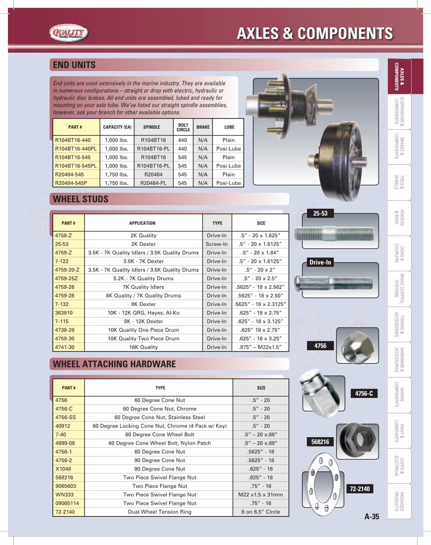
A-35
AXLeS & COMPONeNTSLIG
HTS &
ELECTRICALPAIN
T &LU
BRICANTS
MARIN
ECO
MPO
NEN
TSHARDW
ARE &ACCESSO
RIESTO
WIN
G &
ACCESSORIES
JACKS &CO
UPLERS
BRAKES &CO
MPO
NEN
TSBRAKE CO
NTRO
LSYSTEM
SSU
SPENSIO
NS &
COM
PON
ENTS
TIRES &W
HEELSFEN
DERS&
BODY
AX
LES &CO
MPO
NEN
TSPACKAG
EDPRO
DUCTS
PArT # CAPACiTy (eA) SPiNdLe BOLT BrAke LuBe CirCLe
R104BT16-440 1,000 lbs. R104BT16 440 N/A Plain
R104BT16-440PL 1,000 lbs. R104BT16-PL 440 N/A Posi-Lube
R104BT16-545 1,000 lbs. R104BT16 545 N/A Plain
R104BT16-545PL 1,000 lbs. R104BT16-PL 545 N/A Posi-Lube
R20484-545 1,750 lbs. R20484 545 N/A Plain
R20484-545P 1,750 lbs. R20484-PL 545 N/A Posi-Lube
End units are used extensively in the marine industry. They are available in numerous configurations – straight or drop with electric, hydraulic or hydraulic disc brakes. All end units are assembled, lubed and ready for mounting on your axle tube. We’ve listed our straight spindle assemblies, however, ask your branch for other available options.
eNd uNiTS
WHeeL STudS
PArT # APPLiCATiON TyPe Size
4758-Z 2K Quality Drive-In .5” - 20 x 1.625”
25-53 2K Dexter Screw-In .5” - 20 x 1.8125”
4759-Z 3.5K - 7K Quality Idlers / 3.5K Quality Drums Drive-In .5” - 20 x 1.84”
7-122 3.5K - 7K Dexter Drive-In .5” - 20 x 1.8125”
4759-20-Z 3.5K - 7K Quality Idlers / 3.5K Quality Drums Drive-In .5” - 20 x 2”
4759-25Z 5.2K - 7K Quality Drums Drive-In .5” - 20 x 2.5”
4759-26 7K Quality Idlers Drive-In .5625” - 18 x 2.562”
4759-28 8K Quality / 7K Quality Drums Drive-In .5625” - 18 x 2.50”
7-132 8K Dexter Drive-In .5625” - 18 x 2.3125”
363910 10K - 12K QRG, Hayes, Al-Ko Drive-In .625” - 18 x 2.75”
7-115 9K - 12K Dexter Drive-In .625” - 18 x 3.125”
4738-28 10K Quality One Piece Drum Drive-In .625” 18 x 2.75”
4759-30 10K Quality Two Piece Drum Drive-In .625” - 18 x 3.25”
4741-30 16K Quality Drive-In .975” – M22x1.5”
25-53
drive-in
WHeeL ATTACHiNg HArdWAre
PArT # TyPe Size
4756 60 Degree Cone Nut .5” - 20
4756-C 60 Degree Cone Nut, Chrome .5” - 20
4756-SS 60 Degree Cone Nut, Stainless Steel .5” - 20
40912 60 Degree Locking Cone Nut, Chrome (4 Pack w/ Key) .5” - 20
7-40 60 Degree Cone Wheel Bolt .5” – 20 x.88”
4999-08 60 Degree Cone Wheel Bolt, Nylon Patch .5” – 20 x.88”
4756-1 60 Degree Cone Nut .5625” - 18
4756-2 90 Degree Cone Nut .5625” - 18
X1048 90 Degree Cone Nut .625” - 18
568216 Two Piece Swivel Flange Nut .625” - 18
9065603 Two Piece Flange Nut .75” - 16
WN333 Two Piece Swivel Flange Nut M22 x1.5 x 31mm
09065114 Two Piece Swivel Flange Nut .75” - 16
72-2140 Dual Wheel Tension Ring 8 on 6.5” Circle
4756-C
568216
72-2140
4756
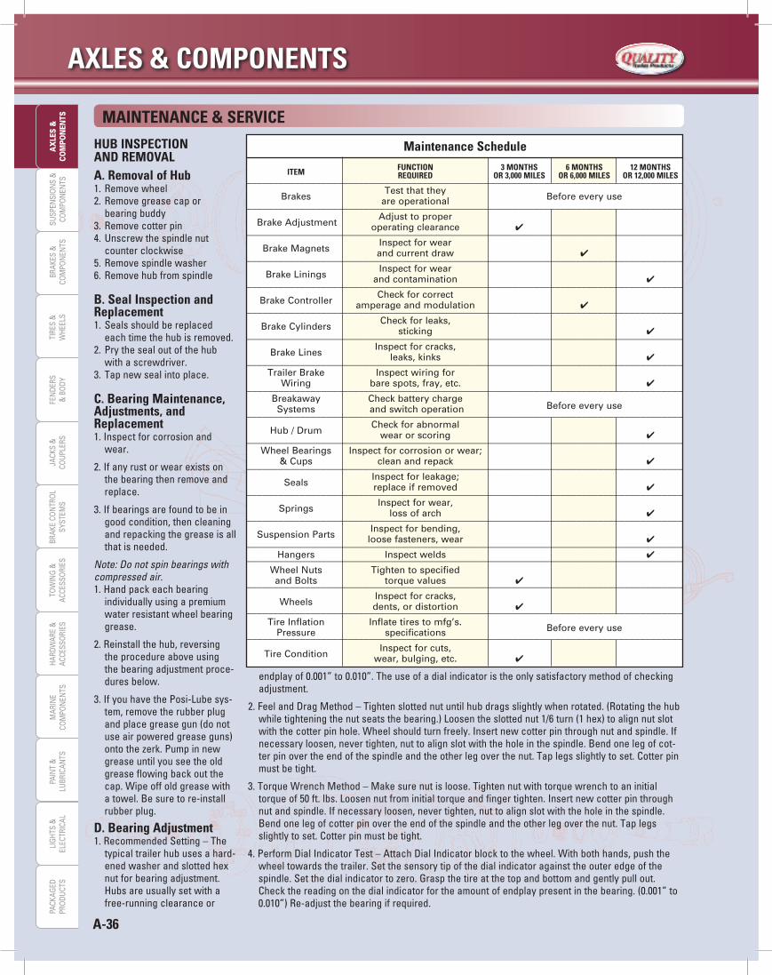
AXLeS & COMPONeNTS
A-36
SUSP
ENSI
ON
S &
COM
PON
ENTS
BRAK
ES &
COM
PON
ENTS
TIRE
S &
WHE
ELS
FEN
DERS
& B
ODY
JACK
S &
COU
PLER
STO
WIN
G &
ACCE
SSO
RIES
PAIN
T &
LUBR
ICAN
TSBR
AKE
CON
TRO
LSY
STEM
SLI
GHT
S &
ELEC
TRIC
ALM
ARIN
ECO
MPO
NEN
TSHA
RDW
ARE
&AC
CESS
ORI
ESPA
CKAG
EDPR
ODU
CTS
AX
LES
&CO
MPO
NEN
TS
HuB iNSPeCTiONANd reMOvALA. removal of Hub
Remove wheel1. Remove grease cap or 2.bearing buddyRemove cotter pin3.Unscrew the spindle nut 4. counterclockwiseRemove spindle washer5.Remove hub from spindle6.
B. Seal inspection and replacement
Seals should be replaced 1. each time the hub is removed.Prythesealoutofthehub2.with a screwdriver.Tap new seal into place.3.
C. Bearing Maintenance, Adjustments, and replacement
Inspectforcorrosionand1. wear.
Ifanyrustorwearexistson2.the bearing then remove and replace.
Ifbearingsarefoundtobein3.good condition, then cleaning andrepackingthegreaseisallthat is needed.
Note: Do not spin bearings with compressed air.
Handpackeachbearing1. individually using a premium water resistant wheel bearing grease.
Reinstall the hub, reversing 2.the procedure above using thebearingadjustmentproce-dures below.
IfyouhavethePosi-Lubesys-3.tem, remove the rubber plug andplacegreasegun(donotuseairpoweredgreaseguns)ontothezerk.Pumpinnewgrease until you see the old greaseflowingbackoutthecap. Wipe off old grease with a towel. Be sure to re-install rubber plug.
d. Bearing AdjustmentRecommended Setting – The 1. typical trailer hub uses a hard-ened washer and slotted hex nutforbearingadjustment.Hubsareusuallysetwithafree-running clearance or
MAiNTeNANCe & ServiCe
endplayof0.001”to0.010”.Theuseofadialindicatoristheonlysatisfactorymethodofcheckingadjustment.
FeelandDragMethod–Tightenslottednutuntilhubdragsslightlywhenrotated.(Rotatingthehub2.whiletighteningthenutseatsthebearing.)Loosentheslottednut1/6turn(1hex)toalignnutslotwiththecotterpinhole.Wheelshouldturnfreely.Insertnewcotterpinthroughnutandspindle.Ifnecessary loosen, never tighten, nut to align slot with the hole in the spindle. Bend one leg of cot-terpinovertheendofthespindleandtheotherlegoverthenut.Taplegsslightlytoset.Cotterpinmust be tight.
TorqueWrenchMethod–Makesurenutisloose.Tightennutwithtorquewrenchtoaninitial3.torqueof50ft.lbs.Loosennutfrominitialtorqueandfingertighten.Insertnewcotterpinthroughnutandspindle.Ifnecessaryloosen,nevertighten,nuttoalignslotwiththeholeinthespindle.Bend one leg of cotter pin over the end of the spindle and the other leg over the nut. Tap legs slightlytoset.Cotterpinmustbetight.
PerformDialIndicatorTest–AttachDialIndicatorblocktothewheel.Withbothhands,pushthe4. wheel towards the trailer. Set the sensory tip of the dial indicator against the outer edge of the spindle.Setthedialindicatortozero.Graspthetireatthetopandbottomandgentlypullout.Checkthereadingonthedialindicatorfortheamountofendplaypresentinthebearing.(0.001”to0.010”)Re-adjustthebearingifrequired.
__________________________________________________________________________________
__________________________________________________________________________________
__________________________________________________________________________________
__________________________________________________________________________________
__________________________________________________________________________________
__________________________________________________________________________________
__________________________________________________________________________________
__________________________________________________________________________________
__________________________________________________________________________________
__________________________________________________________________________________
__________________________________________________________________________________
__________________________________________________________________________________
__________________________________________________________________________________
__________________________________________________________________________________
____________________________________________________________________________________________________________________________________________________________________
__________________________________________________________________________________
__________________________________________________________________________________
__________________________________________________________________________________
Maintenance Schedule iTeM FuNCTiON 3 MONTHS 6 MONTHS 12 MONTHS required Or 3,000 MiLeS Or 6,000 MiLeS Or 12,000 MiLeS
Brakes
Test that they are operational Before every use
Brake Adjustment
Adjust to proper operating clearance 4
Brake Magnets
Inspect for wear and current draw 4
Brake Linings
Inspect for wear and contamination 4
Brake Controller
Check for correct amperage and modulation 4
Brake Cylinders
Check for leaks, sticking 4
Brake Lines
Inspect for cracks, leaks, kinks 4
Trailer Brake Inspect wiring for Wiring bare spots, fray, etc. 4
Breakaway Check battery charge Systems and switch operation Before every use
Hub / Drum
Check for abnormal wear or scoring 4
Wheel Bearings Inspect for corrosion or wear; & Cups clean and repack 4
Seals
Inspect for leakage; replace if removed 4
Springs
Inspect for wear, loss of arch 4
Suspension Parts Inspect for bending,
loose fasteners, wear 4
Hangers Inspect welds 4
Wheel Nuts Tighten to specified and Bolts torque values 4
Wheels
Inspect for cracks, dents, or distortion 4
Tire Inflation Inflate tires to mfg’s. Pressure specifications Before every use
Tire Condition
Inspect for cuts, wear, bulging, etc. 4