Quality Problem Understanding in Crank Case-KWP
40
QUALITY PROBLEM UNDERSTANDING IN CRANK CASE - KWP Birla Institute of Technology and Science, Pilani K.K. Birla Goa Campus 15 July 2011
-
Upload
akshatagha -
Category
Documents
-
view
140 -
download
2
description
Project Done for PS-1 at HMSI
Transcript of Quality Problem Understanding in Crank Case-KWP

QUALITY PROBLEM UNDERSTANDING
IN
CRANK CASE - KWP
Birla Institute of Technology and Science, Pilani
K.K. Birla Goa Campus
15 July 2011

A
Report on QUALITY PROBLEM UNDERSTANDING IN
CRANK CASE - KWP
Submitted in partial fulfillment for the completion of the course
Practice School-I Course No.
BITS C221
AT
Honda Motorcycle & Scooter India Pvt. Ltd.
Prepared by: Under the supervision of: Akshat Agha 2009A4PS380G Mr. Rohit Kumar Mehul Dudi 2009A4PS332P Senior Executive

ACKNOWLEDGEMENT
We, the students of Birla Institute of Technology & Science, Pilani, would like to give
our heartiest thanks to our mentor, Mr. Rohit Kumar for supporting us at every point
of time, and guiding us through the functioning of the various departments in HMSI.
It would have been impossible to work in the industry without his support and
guidance. He also introduced us to various aspects of the project and guided us on
how to proceed with our project.
We would also like to thank Ms. Deep and Mr. Amarjit Singh who allowed us to join
HMSI as trainees, and be a part of this huge organisation. It has given us a very
bright exposure of the industrial world, which would help us to adjust to the new
environment that we will face once we pass out.
We sincerely thank our instructor-in-charge, Mr. William Joe for his cooperation and
support at all points of time.
Finally, we would like to thank Birla Institute of Technology & Science, Pilani
providing us with this opportunity to get an insight into the industrial world.

CERTIFICATE
This is to certify that this project entitled “QUALITY PROBLEM UNDERSTANDING
IN CRANK CASE KWP” submitted by Akshat Agha and Mehul Dudi, students of
Birla Institute of Technology and Science, in the fulfilment of Practice School-I,
Course No. BITS C221, during the academic year 2010-11 is a record of students
own study carried under my supervision & guidance. This project report does not
break any code of confidentiality as per the norms of HMSI.
Mr. Rohit Kumar Mr. Sumit Vij Ms. Deep Raliya
Senior Executive Department Head Trainee Head

BIRLA INSTITUTE OF TECHNOLOGY AND SCIENCE
PILANI (RAJASTHAN)
Station: Honda Motorcycle & Scooter India Pvt. Ltd.
Duration: 2 months Date of Start: May 23, 2011
Date of Submission: July 15, 2011
Title of the project: Quality Problem Understanding in Crank Case KWP
Prepared by:
Akshat Agha 2009A4PS380G B.E. (Hons.) Mechanical Engineering
Mehul Dudi 2009A4PS332P B.E. (Hons.) Mechanical Engineering
Mentor: Mr. Rohit Kumar
PS Faculty: Mr. William Joe
Abstract: This project report aims at understanding the quality in crank case
machining and giving suggestions in order to improve it. The process of crank case
machining is a step-by-step process, and has multiple stages included in it. There
are several problems which occur during the various stages of this process. The
process is a systematic one, which makes the machining both smooth and efficient.
Signatures of Students Signature of PS Faculty
Date: Date:

TABLE OF CONTENTS
About Honda World 8
Corporate Profile 9
Honda’s Products Around The World 11
Honda Motorcycles and Scooters Pvt. Ltd. (HMSI) 12
HMSI Vision 14
Honda Global Network 14
Honda’s Operation in India 14
HMSI Factory at Manesar, Gurgaon 15
Factory Outlook 16
Process Flowchart Of The Plant 17
Aluminium Machining 18
Pre-machining Processes at HPDC Section 20
Final Machining Processes 22
Left Crank Case 26
Right Crank Case 28
Problems in Machining 30
Case Study 31
L/R CD OUT 32
Two way fine boring rejection 35
Bibliography 40

FOUNDER SOICHIRO HONDA
HONDA ESTABLISHED AT HAMAMATSU, JAPAN, IN 1948.
“ACTION WITHOUT PHILOSOPHY
IS A LETHAL WEAPON
PHILOSOPHY WITHOUT ACTION
IS WORTHLESS”
Soichiro Honda
Honda, one of the biggest brand names in the automobile world today was founded by
SOICHIRO HONDA at HAMAMATSU, JAPAN, IN 1948 .Since then, the company has been
growing by leaps and bounds satisfying customers all over the world with its comfortable
world class products having most advanced technology

ABOUT HONDA WORLD
Honda Global Network: Six Regional Head Quarters.
Extensive Worldwide R&D, Production &Sales Networks
FIG. 1: Honda’s Global Network
Head Office
1-1, 2-chome, Minami-Aoyama, Minato-ku, Tokyo 107-8556, Japan
Tel: +81-(0)3-3423-1111
Honda Motor Europe Ltd. (UK)
Asian Honda Motor Co. Ltd. (Thailand)
Honda Motor LTDA. (Brazil)
Honda North America Inc. (USA)Honda Motor Co. Ltd. (Japan)
Honda R&D (China)Honda Motors China Ltd.
Motorcycles Automobiles Power Products Regional Headquarters R&D

CORPORATE PROFILE Honda Motor Co., Ltd. operates under the basic principles of "Respect for the Individual" and
"The Three Joys" — commonly expressed as The Joy of Buying, The Joy of Selling and The Joy of
Creating. "Respect for the Individual" reflects our desire to respect the unique character and
ability of each individual person, trusting each other as equal partners in order to do our best in
every situation. Based on this, "The Three Joys" expresses our belief and desire that each person
working in, or coming into contact with our company, directly or through or products, should
share a sense of joy through that experience.
In line with these basic principles, since its establishment in 1948, Honda has remained on the
leading edge by creating new value and providing products of the highest quality at a reasonable
price, for worldwide customer satisfaction. In addition, the Company has conducted its activities
with a commitment to protecting the environment and enhancing safety in a mobile society.
The Company has grown to become the world's largest motorcycle manufacturer and one of the
leading automakers. With a global network of 507* subsidiaries and affiliates accounted for
under the equity method, Honda develops, manufactures and markets a wide variety of
products, ranging from small general-purpose engines and scooters to specialty sports cars, to
earn the Company an outstanding reputation from customers worldwide.
Honda Motor Company, Limited is a multinational corporation, engine manufacturer and
engineering corporation headquartered in Japan.
The company manufactures automobiles, motorcycles, trucks, scooters, robots, jets and jet
engines, water craft, electrical generators, marine engines, lawn and garden equipment, and
aeronautical and other mobile technologies. Honda's line of luxury cars is branded Acura in
North America, Hondura in the Honduras and Hongda in China. More recently they have
ventured into mountain bikes.
Honda is the 6th largest automobile manufacturer in the world as well as the largest engine-
maker in the world, producing more than 14 million internal combustion engines each year.
As of August 2008, Honda surpassed Chrysler as the 4th largest automobile manufacturer in
the United States. Currently, Honda is the second largest manufacturer in Japan behind
Toyota and ahead of Nissan.

Honda was founded in the late 1940s as Japan struggled to rebuild following the Second
World War Company founder Soichiro Honda first began manufacturing piston rings before
turning his attention to inexpensive motorcycles. Mr. Honda always had a passion for
engineering, and this became evident by the wild sales success of his motorcycles in the
1960s and by competing head-to-head against the world’s best on racetracks. Today, Honda
is a juggernaut, offering class-leading machines in most every category.
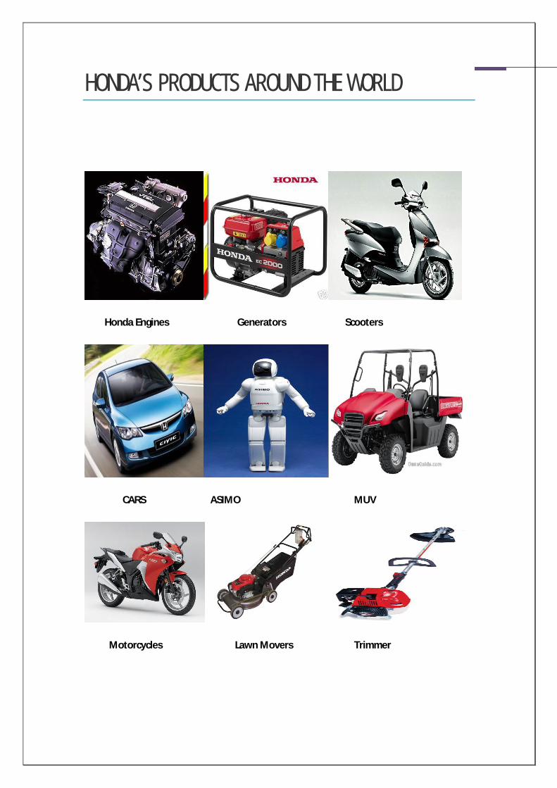
HONDA’S PRODUCTS AROUND THE WORLD
Honda Engines Generators Scooters
CARS ASIMO MUV
Motorcycles Lawn Movers Trimmer

HONDA MOTORCYCLES AND SCOOTERS PVT. LTD. (HMSI)
Honda Motorcycles and Scooters India Pvt. Ltd. (HMSI), a wholly owned subsidiary of Honda
Motor Company Ltd. was incorporated on 20th August 1999 to manufacture two wheelers in
India. It’s Symbol “wings” is recognized all over the world as the symbol of Honda two
wheelers with which they promise to initiate changes and make a difference in the lifestyle
of the people of India. It represents the flight that HMSI has taken to achieve the goals and
targets which conform to the international standards. Honda’s commitment to India is to
manufacture world class two wheelers that are designed and best suited for local conditions.
Ever since its establishment in 1999, HMSI has striven to offer products of the highest quality
at reasonable price by following its fundamental belief of bringing joy to people. In a short

span of ten and half years, HMSI has emerged as the largest scooter manufacturer and the
fourth largest two wheeler company in India. While endeavouring to meet and exceed the
expectations of the customers, the critical importance to providing the product, technology
and service that not only benefits the customer but also the society in areas such as
environment preservation and riding safety is also realized. It is believed at HMSI that by
meeting these expectations, HMSI will enhance the quality of life through products and
services that reflect the spirit of today. Bringing joy to people and contributing to social
development will continue to be the principles that will guide HMSI in future. It came into
mass production with Honda Activa in 2001. Since then, the company has continued to grow
in the Indian market along with regularly providing world class, advanced and technically
sound products. Living up to its illustrious line age of excelling in the manufacture of two
wheelers of global quality, HMSI has revolutionized the multi-dimensional Indian two-
wheeler market with products like Eterno, Dio, Unicorn and Shine. Apart from outstanding
sales, Honda also caters its customers with excellent service and spare parts support. The
HMSI factory is spread over 52 acres, with a covered area of about 85,815 square meters at
Manesar, Gurgaon district of Haryana. The foundation stone for the factory was laid on 14th
December 1999 and the factory was completed in January 2001. The initial installed capacity
was 100,000 scooters per year, which has reached 6,00,000 scooters by the year by 2007 and
motorcycle capacity shall be 4,00,000 per annum. The total investment outlay for the initial
capacity was Rs. 215 crores and now the accumulated investment is 800 crores.
HMSI mainly deals with:-
Manufacturing and sales of two wheelers.
Manufacturing and sales of two wheelers engines.
Service and sales of spare parts and accessories.
Export of Honda products (CBU, Engine & Parts).

HMSI VISION:
HONDA LOGO:
HONDA GLOBAL NETWORK: Honda has 5 operating regions and 1 R& D centre
Honda Motor Corporation Limited, Japan
Honda North America Incorporation, USA
Asian Honda Motor Corporation Limited, Thailand
Honda R&D, China
Honda Motor Limited Association, Brazil Honda Motor Europe Limited, UK
HONDA’S OPERATION IN INDIA: Honda Motor Company, Japan with its headquarters in Tokyo, has manufacturing operations
in 32 countries with 109 production bases. The company principal of Honda Worldwide is
dedication to supplying products of the highest quality yet at a reasonable price for
worldwide customer satisfaction. It has three business divisions namely 2-wheelers, 4-
wheelers and power products. Apart from HMSI that manufactures 2-wheelers, the other
business divisions in India include Honda Siel Cars India Limited (HSCI) and Honda Siel
Power Products Limited (HSPP).

HMSI FACTORY AT MANESAR, GURGAON:
The HMSI factory is spread over 52 acres, with a covered area of about 85,815 square meters
at Manesar, Gurgaon district of Haryana. The foundation stone for the factory was laid was
100,000 scooters per year, which has reached 6, 00,000 scooters by the year by 2007 and
motorcycle capacity shall be 4,00,000 per annum. The total investment outlay for the initial
on 14th December 1999 and the factory was completed in January 2001. The initial installed
capacity was Rs. 215 crores and now the accumulated investment is 800 crores.

FACTORY OUTLOOK
FACTORY MODEL

PROCESS FLOWCHART OF THE PLANT
DISPATCH
The department given to us for our project was Aluminium Department under machining section.
RAW MATERIAL PRESS GDC AL. INGOTS
BOP WELD
PAINT PAINTSHOP
MACHINING CASTING
ENGINE ASSEMBLY
BOP
FRAME ASSEMBLY
VQ
LOGISTICS

ALUMINIUM MACHINING
Aluminium Machining department deals with the machining of aluminium
products used in Honda motorcycles and scooters.
AL-2 is a division of Aluminium department which deals with the
machining of left and right crank cases of KWP, KRP and KYJ models.
Crank case is the body of the engine in which all the other parts are
fitted. The importance of this department can be estimated by the fact
that Honda does the machining process itself inside the factory and takes
only sozai from the venders.
KWP models are manufactured for Honda Activa and Aviator, KRP for
Honda Deo and KYJ for Honda CBR 250.
ALUMINIUM MACHINING-2 consists of two sub-divisions:
Pre-machining processes at HPDC section.
Final Machining Processes.
One-fourth of the required RCCs (KWP type) and LCCs are casted in HPDC
and rest is supplied by venders. Casted LCCs for all models (except a
fraction of KYJ type) are supplied by venders directly to pre-machining
area.

Fig 1. Left Crank Case-KPL
Fig 2. Right Crank Case-KVT

PRE-MACHINING PROCESSES AT HPDC SECTION
In HPDC section, the newly casted components, after cooling, are put into
machining. The casted components from vendors and HPDC are first
treated by hand filers and made free of extra material resulting from
casting. Then the components are sent to pre-machining zone.
There are three lines for pre-machining each one feeding a line at main
machining zone.
The pre-machining starts with Rotary Milling machine.
1. Rotary Milling: The rotary milling machine has a capacity of loading
6 LCCs and 2RCCs at a time. 2 LCCs and 2 RCCs are produced at a
time in the rotary milling machine. There are 3 operations on LCC
and 1 on RCC which include the following:
LCC Mission Face Milling- Roughness 12.5S

LCC Joint Face Milling- Roughness 8S
LCC Cover Face Milling- Roughness 12.5S
RCC Matching Face Milling- Roughness 8S
2. Multi drilling: This is a multi-spindle CNC machine and cuts multiple
drill holes on both LCCs and RCCs.
After this, Sozai is transported on trolleys to Sozai area where the final
machining processes occur. There are three sets of machines for
machining in HPDC section, each one feeds to its respective line in final
machining section.
FINAL MACHINING PROCESSES
There are three lines for machining in AL-2. Each LCC or RCC produced in
any of the three lines bears a marking representing the details of line,
shift and date at which it was produced. The marking of components in
this line is done as <DATE>/<SHIFT CODE>. The three lines of production
are:
1. Line 1 (also known as NEW line): This line has a target of 420
components/shift without reliever and 450 components/shift with
reliever. The shift codes are 1,2 and 3 for A, B and C shifts respectively.
This line produces only KWP model used in Honda Activa and Aviator.
2. Line 2 (also known as OLD line): This line has the same production
capacity as line 1. For this line, the shift codes used in marking are A, B
and C for A, B and C shifts respectively. It also produces only KWP engine
crank cases used in Honda Activa and Aviator.
3. Line 3 (also known as KVT line): This line also having the same capacity
as other two lines produces crank case for KVT engine used in Honda Deo
alongwith KWP engine crank case used in Honda Activa and Aviator. For
this line, the shift codes used in marking are X, Y and Z for A, B and C
shifts respectively.

1. Input-Drill Centre: Input into final machining starts with Drill
Centre. The various operations include reaming, drilling, tapping,
milling, chamfering on LCC and Drilling, tapping, milling on spot
face, reaming, chamfering on RCC.
After this the component is fed into Fine boring machine for very major
operations.
2. Two-Way Fine Boring and Reaming SPM: This is a special purpose
machine which performs boring, reaming, milling and chamfering
operations on LCCs and RCCs. It has a capacity of producing 1 L
case and 1 R case. The important diameters cut on this SPM are:

CI Ring Diameter 62mm on LCC (Hole 65)
Diameter 53mm on LCC (Hole 65)
Diameter 56mm on LCC (Hole 65)
CI Ring Diameter 52mm on RCC (Hole 71)
Diameter 26mm on RCC (Hole 71)
Hanger Hole Diameter 28mm on LCC (Hole 37) and RCC
(Hole 61)
After this, the components are measured for diameters cut on
Two-way fine boring and reaming machine. The components are
checked at a frequency of 1/20 components.
3. Air Gauge Checking: At specified frequencies, the diameters of the
components are checked for any tolerance violations. The fine
boring machine is adjusted as per the results. If the component
comes out to be undersize, it can be re-worked. But, if the
diameter becomes oversize, the component goes to rejection
trolley. Rejection of components takes place at this step so it is a
very crucial step in machining process. By passing of components
at this step can lead to problems in Engine Assembly.
4. Cylinder Face Operations: The components are then machined on
cylinder face, where the gasket and cylinder component rest. There
are 5 holes on LCC and 4 on RCC. After drilling and tapping, milling
operation is performed on cylinder face of the components.
After this, the components pass through a series of operations including
oil hole drilling, tapping on RCC and drilling on LCC.
5. Washing and Air Leak testing: After machining the components are
washed with water and then checked for any leakage resulting due
to casting. It is a two-step surety test. If a component is leak, first
the air leak test detects it, and water test confirms the leak and
sends the component to rejection. The leak components are
rejected and sent for recycling.
After this, a visual inspection and pneumatic cleaning operation is done
on components. If passed, components are marked for <Date>/<Shift
Code> and sent to Engine Assembly.

LEFT CRANK CASE
Figure 3. Joint Face of Left Crank Case-KPL
Figure 4. Cover Face of Left Crank Case-KPL

Figure 5. Cylinder Face of Left Crank Case-KPL

RIGHT CRANK CASE
Figure 6. Joint Face of Right Crank Case-KVT
Figure 7. Cover Face of Right Crank Case-KVT

Figure 8. Cylinder Face of Right Crank Case-KVT

PROBLEMS IN MACHINING
The various problems faced in machining or due to machining can be listed as:
L/R CD Out
Crank Tight
Tapping NG
LCC/RCC Blowhole/Crack
LCC/RCC Leak

CASE STUDY

L/R CD OUT
AIM OF THE PROJECT: Reduction in number of rejected components in Aluminium Machining 2.
The first problem that we had analysed was L/R CD Out. L/R CD out stands for Left/Right crank case centre distance out. When the studs fitted in hole number 94, 95 in RCC and 100, 101 in LCC are not at their proper position, it creates a problem in Engine Assembly. The gasket breaks on mounting over the studs followed by problem in cylinder component installation over the cylinder faces of LCC and RCC.

ERROR DETECTION:
Gasket breaks during fitting in AE because the studs on which it is mounted are not exactly in the place where they are supposed to be. The distance between the studs varies by more than 25 micron from their given distance in the design.
Problems in Cylinder component fitment as like the gasket the cylinder component is also mounted on the studs that are out of place by more than 25 micron from their given distance in the design.
Visually, studs appear bent and non-planar which causes problems in assembly.
FINDINGS: From collected data, it is clearly visible that most number of LCC’s having CD-Out
come from Line-1(New line) of AL-2.
Line 2(Old line) gives maximum number of faulty R cases which when assembled with line 1’s L cases gives CD Out.
CMM Reports of the holes of faulty cases are OK. Center of the holes are under tolerance limits.
Studs were taken out and checked for planarity. The report was OK.
More number of cases of CD-Out are recorded in B-shift as compared to A-shift ranging from an average of 10 to 4.
When studs are taken out, cleaned and re-tightened, the engine sometimes becomes OK.
POSSIBLE CAUSES: Seal check sensors in cylinder face drilling machines do not work sometimes.
Wrong loading of components.
Improper washing- Presence of chips inside drilled holes.
Studs, if bent can cause problem in proper fitment of gasket and give CD-Out.
Sometimes, the operator tightens the stud directly by pneumatic-gun. A disoriented stud can also be tightened by massive force of gun.

When stud is excessively tightened, it twists and bends, giving CD Out.
SUGGESTIONS: Proper coolant flow has been provided on the fixtures in cylinder face drilling
and tapping machines. This will ensure proper cleaning of fixtures and no accumulation of chips on rest pads.
In Line-1, there is an improper fixture in milling machine (Batliboi), due to which the LCC becomes tight and the locating hole gets a dent. The same hole is used to fix the component in Cylinder face drilling and tapping machines. The fixture needs to be fixed.
Seat check sensors need to be fixed.
Components should be properly cleaned and no chips should be present inside the holes.
Studs should first be tightened for 2-3 threads by hand and then gun should be used. This will ensure proper placement of stud inside the hole. This is why engine becomes OK when studs are opened and re-tightened.
Some erroneous reporting was also observed about this problem in AE. This may be a reason more number of problems are registered in B-shift as compared to A-shift.

2 WAY FINE BORING REJECTION
1) DIAMETER UNDERSIZE:
This error occurs when the diameter of the hole in LCC or RCC is lower than the
tolerance prescribed. This error is detected using air gauges at the inspection station
after the 2 way fine boring SPM. If bypassed this is detected, as a crank tight or crank
loose error if the diameter in question is one of the cast iron ring (CI ring) diameters
otherwise it is detected as a normal diameter NG, in the Engine Assembly.
2) DIAMETER OVERSIZE:
This error occurs when the diameter of the hole in LCC or RCC is higher than the
tolerance prescribed. This error is detected using air gauges at the inspection station
after the 2 way fine boring SPM.
3) DIAMETER UNCLEAN:
This error occurs when the finishing of the inside of the hole is improper, this mainly
occurs when the insert is worn out. It is detected by the machine operator by visual
inspection.
4) SURFACE UNCLEAN:
This error occurs when the finishing of the surface above the hole is improper, this
error is mainly detected in Line3 (KVT line) RCC and occurs when excess milling is
done on the joint face in the pre-machining area. It is detected by the machine
operator by visual inspection.
OBSERVATIONS: According to the above data on rejection it is clear that the new line or Line1 shows the
maximum amount of rejection. This may be attributed to the fact that the 2 way fine boring
MICO SPM reports regular tight fitting problems in the LCC. The locating hole of the LCC is
unable to mount on the locating pin which is fitted on the rest pad of the fixture. This forces
the operator to hit the work piece with a hammer after mounting the work piece to force it
into place. This sometimes results in wrong loading of component and causes the work piece
to be rejected.
Collected data also shows that Line3 (KVT line) reports multiple rejections every day for
unclean surfaces in the RCC. This problem only occurs when the KVT model is being
produced in the line and it never occurs during the production of KWPA model.
The inserts used in the boring bars of all three lines are used past their prescribed lifetime.
The inserts are changed only when they either shatter or the holes which they are machining
start to come out unclean. When this happens the boring bars have to be readjusted to the
new inserts which sometimes results in some pieces getting rejected due to oversized
diameters.
While machining the inserts in the boring bars are continuously getting worn out, this result
in the diameter which they are machining getting gradually smaller. This diameter eventually
goes below the tolerance limit making the component undersize. Since the frequency of
checking is 1/20 there is a probability of having a maximum of 20 components undersize
before the error is detected. This is a very large number and the chances of it happening are
very low but the probability of having 10 pieces undersize is very large and often it occurs
resulting in a large number of components requiring rework and hence increasing the day’s
loss.
When the inserts are changed in the machine generally 2-3 components are rejected during
adjustment as adjustment is done using approximation and by the means of trial and error.

POSSIBLE CAUSES:
One of the major causes of rejection in the 2 way fine boring machines is operator
negligence. This may occur in many different forms; like an operator in a hurry may forget to
properly locate the work piece on the rest pad and it may cause the resulting diameter to be
outside tolerance limits. He can also forget to replace the tool in time or to clean the
machine to get rid of the chips on the boring bar and on the rest pad which causes damage
to the inserts and interferes with the seat check sensors present in the machines. This can
also result in damages to the sensor and it may stop working which augments the earlier
problem of wrong loading. Another form of operator negligence is when the operator
forgets to clean the work piece prior to placing it in the machine, which results in the chips
on the work piece damaging the inserts. If the tool is not replaced in time eventually it
shatters or starts giving an unclean diameter which causes that component to be rejected.
Sometimes, like in the case of the MICO SPM, the machine makes it difficult for the operator
to properly place the component in the machine. The locating pin in the machine does not fit
properly in the locating hole of the LCC. This is due to the diameter of the pin being larger
than what is required for fitting in the hole. This may also be due to the denting of the
locating hole of the LCC in the Batliboi machine. The locating pin on the rest pad of the
Batliboi machine is slightly displaced from its proper position and the diameter of the
locating pin is slightly larger than normal. Due to this the operator is merely able to place the
LCC on the locating pin and is not able to fit the piece on it. Then the hydraulic clamps exert a
large amount of force and forcibly fit the hole on the pin resulting in a dent on the hole
which makes the hole oblong and unsuitable for locating in other machines.
Machines are not inspected very frequently as the operator assumes that till the machine is
giving out components which are OK the machine is fine, but in reality the machines require
frequent inspections in order to avoid rejections. If the machine is not inspected then any
snag that it has developed is not detected until and unless a rejected piece is detected which
is a scenario that we wish to avoid.
The major error prone diameters are inspected at a frequency of 1/20. Since the frequency
of checking is 1/20 there is a probability of having a maximum of 20 components undersize
before the error is detected. This is a very large number and the chances of it happening are
very low but the probability of having 10 pieces undersize is very large and often it occurs
resulting in a large number of components requiring rework and hence increasing the loss.

But even though this frequency is inadequate sometimes, the operator does not check the
diameters at the specified frequency, instead he opts to rely on his own experience. This
may be fine with an experienced operator with an eye for errors but even with experience
the rejection may occur long before it is detected and it may result in trolley full of rejection
in a single go.
The diameters machined by the 2 way fine boring machines, are checked by using air gauges.
These air gauges are highly accurate but require constant calibration against a standard
diameter as they lose their accuracy with constant use. If an operator neglects recalibration
of the gauges he may end up marking defective components as OK.
The method of trial and error used by operators while changing inserts to adjust the
diameter is highly susceptible to cause rejection. The success of this method is highly
dependent on luck and experience of the operator. In case of an inexperienced operator
there may be a large number of rejections during adjustment which is unacceptable. Since
the operator has no way to predetermine the diameter of the hole to be machined nor does
he have a means to detect the correct amount of adjustment that he has just made.

SUGGESTIONS: The oversized locator pin in the Batliboi machine in Line1 should be reduced in diameter and
fixed in a place which is according to the dimensions of the work piece. This would remove
the dent that is caused in the locating hole and would facilitate the proper fitting of the LCC
in the MICO SPM. The locating pin of the MICO SPM should also be reduced in diameter so
that the operator can fit the component easily and without using force.
The machines should be inspected at proper intervals to ensure that no snag has developed
and that all the sensors present in the machine are working properly. The chips present on
the rest pad and the boring bars should be removed but care should be taken that the boring
bar is not cleaned with compressed air as it damages the settings of the inserts and may
cause rejection. The lubrication and the state of the inserts should also be regularly
inspected to prevent the shattering of inserts and getting unclean diameters. It must be
ensured that the inserts are changed at proper intervals according to the lifetime specified
by the manufacturers of the inserts.
Before loading component should be properly cleaned and it must be ensured that there are
no chips on the seat check sensors on the rest pad of the machine. This ensures that the
insert is not damaged by chips and that the seat check sensors on the pad trigger in case of
wrong loading of the component which helps in reducing rejection due to wrong loading
The frequency of checking the major diameters should be increased and it should be ensured
that it is being followed. This allows for early detection of the component going out of the
tolerance limit. This also reduces the maximum number of rejections possible
probabilistically hence reducing the chances of rejection.
New technology like digital boring bars should be used to help the operator reduce manual
errors. These boring bars allow the operator to monitor the size of the hole to be machined
even before the component is mounted on the machine. This allows the operator to adjust
the size of the hole beforehand hence reducing the chances for rejection. These digital bars
allow the operator to adjust the fine bore to an accuracy of 1 micron which is very large
compared to the tolerance limit of 15 microns in case of the 62 mm diameter. This coupled
with tool break sensors can give the machine a sense of automation in which it only relies on
the operator to load and unload components and in case of a broken tool to replace the tool,
as the bars can adjust themselves to stay at the mean of the tolerance limit of the diameter
of the hole. This eliminates the errors caused due to the trial and error followed by operators
when they change inserts while using mechanical boring bars.
BIBLIOGRAPHY www.honda2wheelers.com
www.hondaworld.com
Conversations with concerned people.
List of persons consulted:
1. Mr. Rohit Kumar San
2. Mr. Sumit Vij San
3. Mr. Chandrashekhar San
4. Mr. Tulsiram Badhe San
5. Mr. Jignesh Prajapati San
6. Mr. Brijendra Singh Chauhan San
7. Mr. Dua San
8. Mr. Das
9. Mr. Gaurav Bhatia San
The executives mentioned above served as the key informants to this report. The methodologies used for information collection are:
1. Desk reviews.
2. Discussions with concerned employees at HMSI.