Q:RV-12ManualFINISHSECTION 32 FLIGHT …vansaircraft.com/pdf/revisions/RV-12/RV-12_32.pdf ·...
16
14401 Keil Road NE, Aurora, Oregon, USA 97002 PHONE 503-678-6545 FAX 503-678-6560 www.vansaircraft.com [email protected] Service Letters and Bulletins: www.vansaircraft.com/public/service.htm REVISION DESCRIPTION: 07-06-15 Page: 32-01 REV 1: Updated overall figure with depiction of new VA-110 Detent Bracket configuration Page 32-07 REV 1: Updated Figure 5 and Figure 6 with depiction of new F-1266AD configuration New Step 7 New Step 13 Note will be added to Maintenance Manual at next rev change regarding F-1266AD greasing at annual inspection. Page: 32-08 REV 2: Updated Figure 1 and Figure 2 with depiction of new F-1266AD configuration Page: 32-09 REV 2: Updated Figure 2 with depiction of new F-1266AD and VA-110 configuration REVISION DESCRIPTION: 09-29-14 1) Page: 32-03 MEMO: Step 4 should not be bold. Fix WD-1213 callout in Figure 3. Page: 32-04 REV 3: Add drill and tap information to Figure 4 “DRILL #3, TAP 1/4-28 BOTH ENDS”. Add make from material “AT6-058X5/16” to Step 4. Page: 32-05 REV 1: Remove make from material from Figure 1. 2) Page 32-14 REV 3: Add a note before Step 6 “NOTE: Cable tension will change significantly with changing temperature. The cable tensions given below are for an aircraft inside a 70 OF hanger.” In Figure 2 “GROOVE AROUND BARREL TOWARD AFT…” was “GROOVE AROUND BARREL TOWARD FWD…” 3) Page 32-08 REV 1: Added Step 10. Page: 32-09 REV1: In Step 1, changed grommet cut length from 3-3/16 to 3-11/16. In Step 4, changed: “Install the wings. During installation, slide the A-1211 Pivot Guides into the WD-1214-L & -R Flaperon Torque Tubes and the A-1207-L & -R Actuation Brackets between the F- 1261 Spacers as shown in Figure 4.” To: “Install the wings. During installation, use axle grease to lubricate the A-1211 Pivot Guides and A-1207-L & -R Actuation Brackets. The pivot guides slide into the WD- 1214-L & -R Flaperon Torque Tubes and the actuation brackets slide between the F- 1261 Spacers as shown in Figure 3.”
Transcript of Q:RV-12ManualFINISHSECTION 32 FLIGHT …vansaircraft.com/pdf/revisions/RV-12/RV-12_32.pdf ·...
14401 Keil Road NE, Aurora, Oregon, USA 97002
PHONE 503-678-6545 FAX 503-678-6560 www.vansaircraft.com [email protected] Service Letters and Bulletins: www.vansaircraft.com/public/service.htm
REVISION DESCRIPTION: 07-06-15 Page: 32-01 REV 1: Updated overall figure with depiction of new VA-110 Detent Bracket configuration Page 32-07 REV 1: Updated Figure 5 and Figure 6 with depiction of new F-1266AD configuration New Step 7 New Step 13 Note will be added to Maintenance Manual at next rev change regarding F-1266AD greasing at annual inspection. Page: 32-08 REV 2: Updated Figure 1 and Figure 2 with depiction of new F-1266AD configuration Page: 32-09 REV 2: Updated Figure 2 with depiction of new F-1266AD and VA-110 configuration REVISION DESCRIPTION: 09-29-14 1) Page: 32-03 MEMO: Step 4 should not be bold. Fix WD-1213 callout in Figure 3. Page: 32-04 REV 3: Add drill and tap information to Figure 4 “DRILL #3, TAP 1/4-28 BOTH ENDS”. Add make from material “AT6-058X5/16” to Step 4. Page: 32-05 REV 1: Remove make from material from Figure 1. 2) Page 32-14 REV 3: Add a note before Step 6 “NOTE: Cable tension will change significantly with changing temperature. The cable tensions given below are for an aircraft inside a 70 OF hanger.” In Figure 2 “GROOVE AROUND BARREL TOWARD AFT…” was “GROOVE AROUND BARREL TOWARD FWD…” 3) Page 32-08 REV 1: Added Step 10. Page: 32-09 REV1: In Step 1, changed grommet cut length from 3-3/16 to 3-11/16. In Step 4, changed: “Install the wings. During installation, slide the A-1211 Pivot Guides into the WD-1214-L & -R Flaperon Torque Tubes and the A-1207-L & -R Actuation Brackets between the F- 1261 Spacers as shown in Figure 4.” To: “Install the wings. During installation, use axle grease to lubricate the A-1211 Pivot Guides and A-1207-L & -R Actuation Brackets. The pivot guides slide into the WD- 1214-L & -R Flaperon Torque Tubes and the actuation brackets slide between the F- 1261 Spacers as shown in Figure 3.”

14401 Keil Road NE, Aurora, Oregon, USA 97002
PHONE 503-678-6545 FAX 503-678-6560 www.vansaircraft.com [email protected] Service Letters and Bulletins: www.vansaircraft.com/public/service.htm
Lubrication of the pivot guides and actuation brackets are added to the RV-12 Maintenance Manual in 12CN 01-01-15-1. REVISION DESCRIPTION: 08-12-13 32-2 REV 2: Step 2 revised to describe FLF-00004 Male Nylon Tee installation (vice F 271-N-04X02) installation. 32-10 REV 1: Step 1 updated to describe shimming and clamping the flaperons prior to drilling the torque tubes. Figure 1 updated to show shims and clamps.
32-0107/06/15 1 RV-12
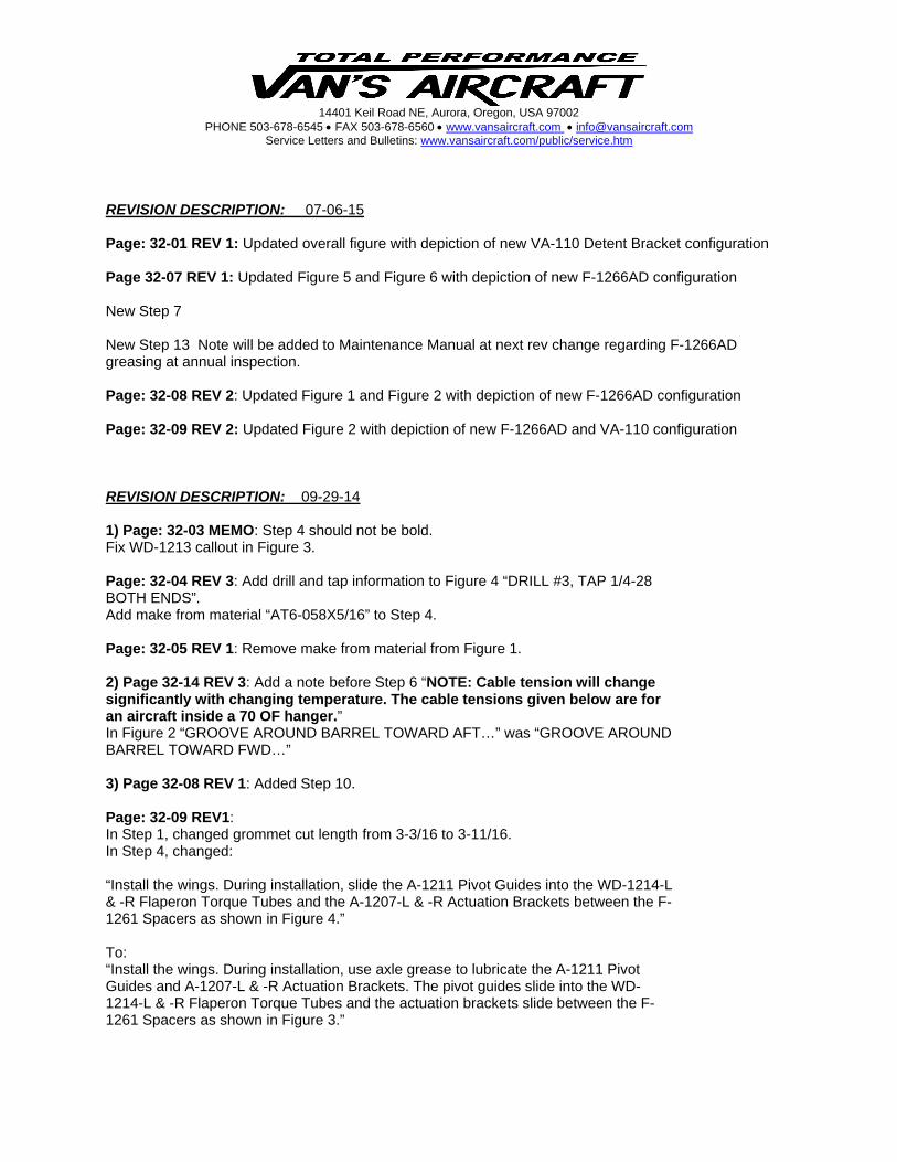
SECTION 32:FLIGHT CONTROLS
DATE OF COMPLETION:
PARTICIPANTS:
WD-1206RUDDER PEDAL
2 PLACES
F-1239RUDDER CABLE
2 PLACES
WD-1212CONTROL STICK
2 PLACES
WD-1210CONTROL COLUMN
F-1264CONTROL STICK PUSHROD
2 PLACES
F-1265FLAPERON PUSHROD
2 PLACES
F-1263AFLAPERON MIXER
BELLCRANK
F-1263BFLAPERON MIXER
BELLCRANKWD-1213
FLAP HANDLE
F-1247AFWD STABILATOR CABLE2 PLACES
F-1247BAFT STABILATOR CABLE2 PLACES
WD-1214-LFLAPERON TORQUE TUBE
WD-1215-LFLAPERONTORQUE ARM
WD-1215-RFLAPERONTORQUE ARM
VA-110FLAP KNOB
WD-1216FLAP HANDLE
PUSHROD
PAGEREVISION:DATE:
VAN'S AIRCRAFT, INC.
DATE: REVISION:
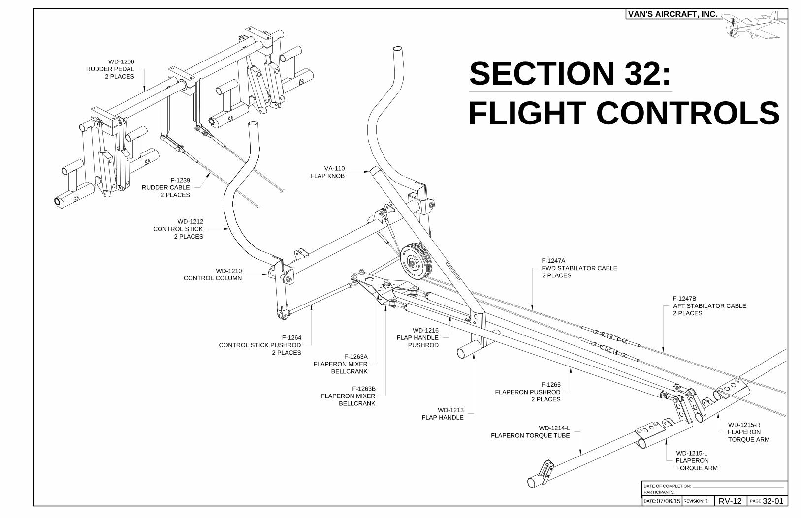
NOTE: Before proceeding with this section return to page 12-04 Step 4 andcomplete the remainder of Section 12 leaving the em pennage attached.
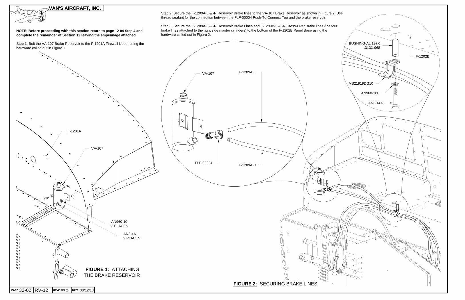
Step 1: Bolt the VA-107 Brake Reservoir to the F-1201A Firewall Upper using thehardware called out in Figure 1.
FIGURE 1: ATTACHINGTHE BRAKE RESERVOIR
Step 2: Secure the F-1289A-L & -R Reservoir Brake lines to the VA-107 Brake Reservoir as shown in Figure 2. Usethread sealant for the connection between the FLF-00004 Push-To-Connect Tee and the brake reservoir.
Step 3: Secure the F-1289A-L & -R Reservoir Brake Lines and F-1289B-L & -R Cross-Over Brake lines (the fourbrake lines attached to the right side master cylinders) to the bottom of the F-1202B Panel Base using thehardware called out in Figure 2.
VA-107
AN3-4A2 PLACES
AN960-102 PLACES
F-1201A
FIGURE 2: SECURING BRAKE LINES
AN3-14A
F-1202B
MS21919DG10
AN960-10L
BUSHING-AL.197X.313X.968
PAGE REVISION: DATE:
VAN'S AIRCRAFT, INC.
08/12/13PAGE 32-02 RV-12 REVISION: 2 DATE:PAGE REVISION: DATE:
VAN'S AIRCRAFT, INC.
PAGE
FLF-00004
VA-107 F-1289A-L
F-1289A-R

Step 1: Separate the F-1263 Flaperon Mixer Bellcrank into individual parts by removing the shaded areas shown in Figure 1.
FIGURE 1: SEPARATINGTHE F-1263 FLAPERON MIXER BELLCRANK
FIGURE 2: ATTACHING THEFLANGE BEARINGS
Step 2: Rivet the VA-146 Flange Bearings to the F-1263A & B Flaperon Mixer Bellcranks using therivets called out in Figure 2.
F-1263B
F-1263A
VA-146
F-1263A
F-1263B
FIGURE 3: FLAPHANDLE/ PUSHROD
ASSEMBLY
Step 3: Make the Flap Handle/ Pushrod Assembly using the parts andhardware shown in Figure 3. Thread in the rod-end bearings to attainthe dimension given in the figure (note that the dimension is from thecenterline of the rod-end bearing to the edge of the WD-1213 FlapHandle).
11 25/32
WD-1216
WD-1213
AN316-4R2 PLACES
CM-4M
WD-1216 WD-1213
LP4-36 PLACES
LP4-36 PLACES
VA-146
PAGEREVISION:DATE:
VAN'S AIRCRAFT, INC.
DATE: 32-03109/29/14 REVISION: RV-12 PAGE
FIGURE 4: BRACKETMODIFICATION
Step 4: The bend nearthe radius cut on theF-00050 Wire RoutingBracket may need to beadjusted using a vice anda plastic hammer or witha hand seamer as calledout in Figure 1. This bendaffects the placement ofthe attachment holes.
Use a vice grip and bendby hand the F-00050Wire Routing Bracket asshown in Figure 4.
BEND 25°, ADJUSTAS NECESSARY,
2 PL
1/2 [12.7 mm]
F-00050
PAGEREVISION:DATE:
VAN'S AIRCRAFT, INC.
ADJUST BY HAND
32-04 09/29/143RV-12
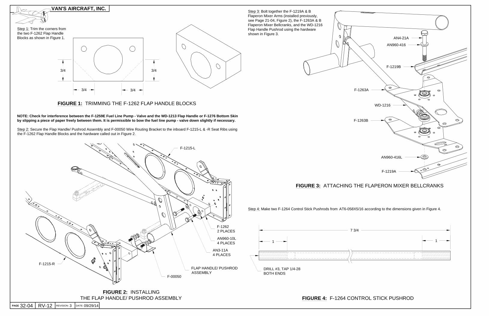
Step 1: Trim the corners fromthe two F-1262 Flap HandleBlocks as shown in Figure 1.
FIGURE 2: INSTALLINGTHE FLAP HANDLE/ PUSHROD ASSEMBLY
FIGURE 1: TRIMMING THE F-1262 FLAP HANDLE BLOCKS
NOTE: Check for interference between the F-1259E Fu el Line Pump - Valve and the WD-1213 Flap Handle or F-1276 Bottom Skinby slipping a piece of paper freely between them. I t is permissible to bow the fuel line pump - valve down slightly if necessary.
Step 2: Secure the Flap Handle/ Pushrod Assembly and F-00050 Wire Routing Bracket to the inboard F-1215-L & -R Seat Ribs usingthe F-1262 Flap Handle Blocks and the hardware called out in Figure 2.
3/4 3/4
3/43/4
Step 3: Bolt together the F-1219A & BFlaperon Mixer Arms (installed previously,see Page 21-04, Figure 2), the F-1263A & BFlaperon Mixer Bellcranks, and the WD-1216Flap Handle Pushrod using the hardwareshown in Figure 3.
Step 4: Make two F-1264 Control Stick Pushrods from AT6-058X5/16 according to the dimensions given in Figure 4.
FIGURE 3: ATTACHING THE FLAPERON MIXER BELLCRANKS
7 3/4
FIGURE 4: F-1264 CONTROL STICK PUSHROD
1 1
F-1263A
F-1263B
AN4-21A
AN960-416L
AN960-416
F-1219A
F-1219B
WD-1216
F-12622 PLACES
AN960-10L4 PLACES
AN3-11A4 PLACES
FLAP HANDLE/ PUSHRODASSEMBLY
F-1215-L
F-1215-R
F-00050
PAGE REVISION: DATE:
VAN'S AIRCRAFT, INC.
PAGE
DRILL #3, TAP 1/4-28BOTH ENDS
32-0509/29/14 1 RV-12
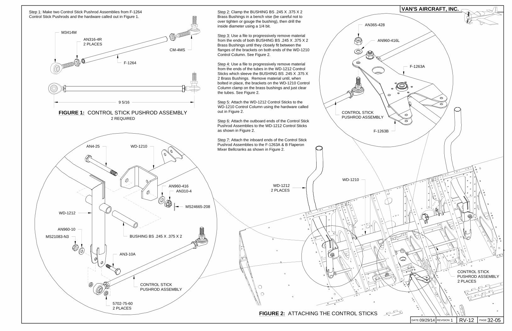
Step 1: Make two Control Stick Pushrod Assemblies from F-1264Control Stick Pushrods and the hardware called out in Figure 1.
FIGURE 2: ATTACHING THE CONTROL STICKS
FIGURE 1: CONTROL STICK PUSHROD ASSEMBLY2 REQUIRED
F-1264
CM-4MS
M3414M
AN316-4R2 PLACES
Step 2: Clamp the BUSHING BS .245 X .375 X 2Brass Bushings in a bench vise (be careful not toover tighten or gouge the bushing), then drill theinside diameter using a 1/4 bit.
Step 3: Use a file to progressively remove materialfrom the ends of both BUSHING BS .245 X .375 X 2Brass Bushings until they closely fit between theflanges of the brackets on both ends of the WD-1210Control Column. See Figure 2.
Step 4: Use a file to progressively remove materialfrom the ends of the tubes in the WD-1212 ControlSticks which sleeve the BUSHING BS .245 X .375 X2 Brass Bushings. Remove material until, whenbolted in place, the brackets on the WD-1210 ControlColumn clamp on the brass bushings and just clearthe tubes. See Figure 2.
Step 5: Attach the WD-1212 Control Sticks to theWD-1210 Control Column using the hardware calledout in Figure 2.
Step 6: Attach the outboard ends of the Control StickPushrod Assemblies to the WD-1212 Control Sticksas shown in Figure 2.
Step 7: Attach the inboard ends of the Control StickPushrod Assemblies to the F-1263A & B FlaperonMixer Bellcranks as shown in Figure 2.
9 5/16
WD-1210AN4-25
AN960-416AN310-4
BUSHING BS .245 X .375 X 2
5702-75-602 PLACES
AN3-10A
AN960-10
MS21083-N3
WD-1212
CONTROL STICKPUSHROD ASSEMBLY
CONTROL STICKPUSHROD ASSEMBLY
AN960-416L
AN365-428
F-1263A
F-1263B
WD-12122 PLACES
WD-1210
CONTROL STICKPUSHROD ASSEMBLY2 PLACES
MS24665-208
PAGEREVISION:DATE:
VAN'S AIRCRAFT, INC.

32-06 03/06/080RV-12
FIGURE 3: ATTACHINGTHE FLAPERON TORQUE ARMS
Step 4: Bolt the WD-1215-L &-R Flaperon Torque Arms to the F-1206D Bearing Brackets using the hardware shown in Figure 3.
Step 5: Attach the aft end of the Flaperon Pushrod Assemblies to the WD-1215-L & -RFlaperon Torque Arms using the hardware called out in Figure 3.
FIGURE 1: FLAPERON PUSHROD ASSEMBLY2 REQUIRED
FIGURE 2: ATTACHING THE FLAPERON PUSHROD ASSEMBLIES
WD-1215-R
AN3-7A
AN960-103 PLACES
MS21083-N3
F-1206D
WD-1215-R
WD-1215-L
FLAPERON PUSHRODASSEMBLY
AN3-10A
AN960-102 PLACES
MS21083-N3
WD-1215-R
Step 2: Pass the two Flaperon Pushrod Assemblies through their corresponding oblong holes in the F-1204A & D Center SectionBulkheads and the center lightening hole in the F-1206A Bulkhead.
Step 3: Bolt the forward end of both Flaperon Pushrod Assemblies to the F-1263A & B Flaperon Mixer Bellcranks using the hardwarecalled out in Figure 2.
Step 1: Make the two Flaperon Pushrod Assemblies using the F-1265 Flaperon Pushrodsand the hardware called out in Figure 1. After drilling, remember to markthe parts for reassembly.
38 3/4
DRILL #30 FOR MSP-42 RIVETS,4 PLACES EVENLY SPACED,BOTH ENDS
5/16
34 5/8
F3514M2 PLACES
AN316-5R2 PLACES
AN490HT11P-SDM 0.6342 PLACES
F-1265(MAKE FROM AT6-058X3/4)
AN960-10L
AN3-7A
MS21083-N3
FLAPERON PUSHRODASSEMBLY, 2 PLACES
PAGE REVISION: DATE:
VAN'S AIRCRAFT, INC.
PAGE
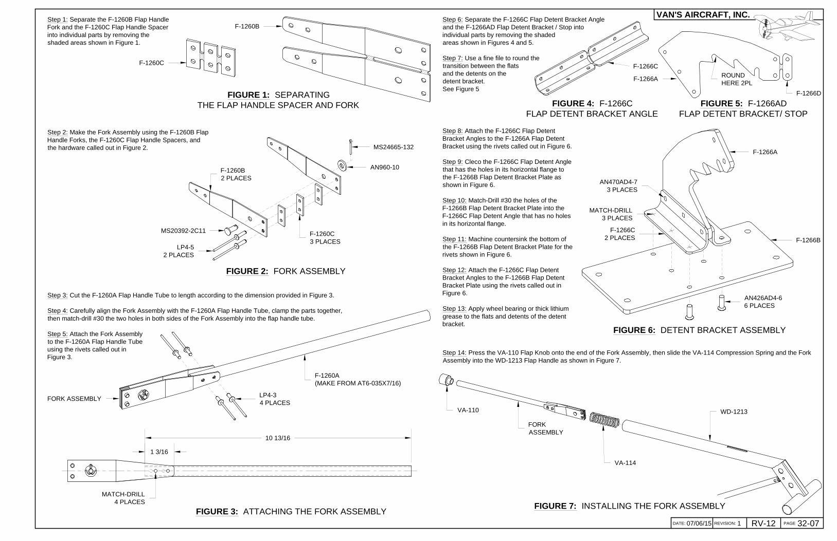
32-0707/06/15 1 RV-12FIGURE 3: ATTACHING THE FORK ASSEMBLY
Step 1: Separate the F-1260B Flap HandleFork and the F-1260C Flap Handle Spacerinto individual parts by removing theshaded areas shown in Figure 1.
Step 6: Separate the F-1266C Flap Detent Bracket Angleand the F-1266AD Flap Detent Bracket / Stop intoindividual parts by removing the shadedareas shown in Figures 4 and 5.
Step 7: Use a fine file to round thetransition between the flatsand the detents on thedetent bracket.See Figure 5
FIGURE 7: INSTALLING THE FORK ASSEMBLY
FIGURE 2: FORK ASSEMBLY
FIGURE 1: SEPARATINGTHE FLAP HANDLE SPACER AND FORK
Step 2: Make the Fork Assembly using the F-1260B FlapHandle Forks, the F-1260C Flap Handle Spacers, andthe hardware called out in Figure 2.
Step 3: Cut the F-1260A Flap Handle Tube to length according to the dimension provided in Figure 3.
Step 4: Carefully align the Fork Assembly with the F-1260A Flap Handle Tube, clamp the parts together,then match-drill #30 the two holes in both sides of the Fork Assembly into the flap handle tube.
Step 5: Attach the Fork Assemblyto the F-1260A Flap Handle Tubeusing the rivets called out inFigure 3.
1 3/16
10 13/16
F-1260C
F-1260B
MATCH-DRILL4 PLACES
LP4-34 PLACES
F-1260C3 PLACES
F-1260B2 PLACES
MS24665-132
AN960-10
MS20392-2C11
LP4-52 PLACES
FORK ASSEMBLY
F-1260A(MAKE FROM AT6-035X7/16)
FIGURE 4: F-1266CFLAP DETENT BRACKET ANGLE
Step 8: Attach the F-1266C Flap DetentBracket Angles to the F-1266A Flap DetentBracket using the rivets called out in Figure 6.
Step 9: Cleco the F-1266C Flap Detent Anglethat has the holes in its horizontal flange tothe F-1266B Flap Detent Bracket Plate asshown in Figure 6.
Step 10: Match-Drill #30 the holes of theF-1266B Flap Detent Bracket Plate into theF-1266C Flap Detent Angle that has no holesin its horizontal flange.
Step 11: Machine countersink the bottom ofthe F-1266B Flap Detent Bracket Plate for therivets shown in Figure 6.
Step 12: Attach the F-1266C Flap DetentBracket Angles to the F-1266B Flap DetentBracket Plate using the rivets called out inFigure 6.
Step 13: Apply wheel bearing or thick lithiumgrease to the flats and detents of the detentbracket.
AN470AD4-73 PLACES
F-1266A
F-1266B
F-1266C2 PLACES
FIGURE 6: DETENT BRACKET ASSEMBLY
Step 14: Press the VA-110 Flap Knob onto the end of the Fork Assembly, then slide the VA-114 Compression Spring and the ForkAssembly into the WD-1213 Flap Handle as shown in Figure 7.
VA-110
FORKASSEMBLY
VA-114
WD-1213
MATCH-DRILL3 PLACES
AN426AD4-66 PLACES
FIGURE 5: F-1266ADFLAP DETENT BRACKET/ STOP
F-1266D
PAGEREVISION:DATE:
VAN'S AIRCRAFT, INC.
F-1266A ROUNDHERE 2PL
F-1266C
32-08 07/06/152RV-12
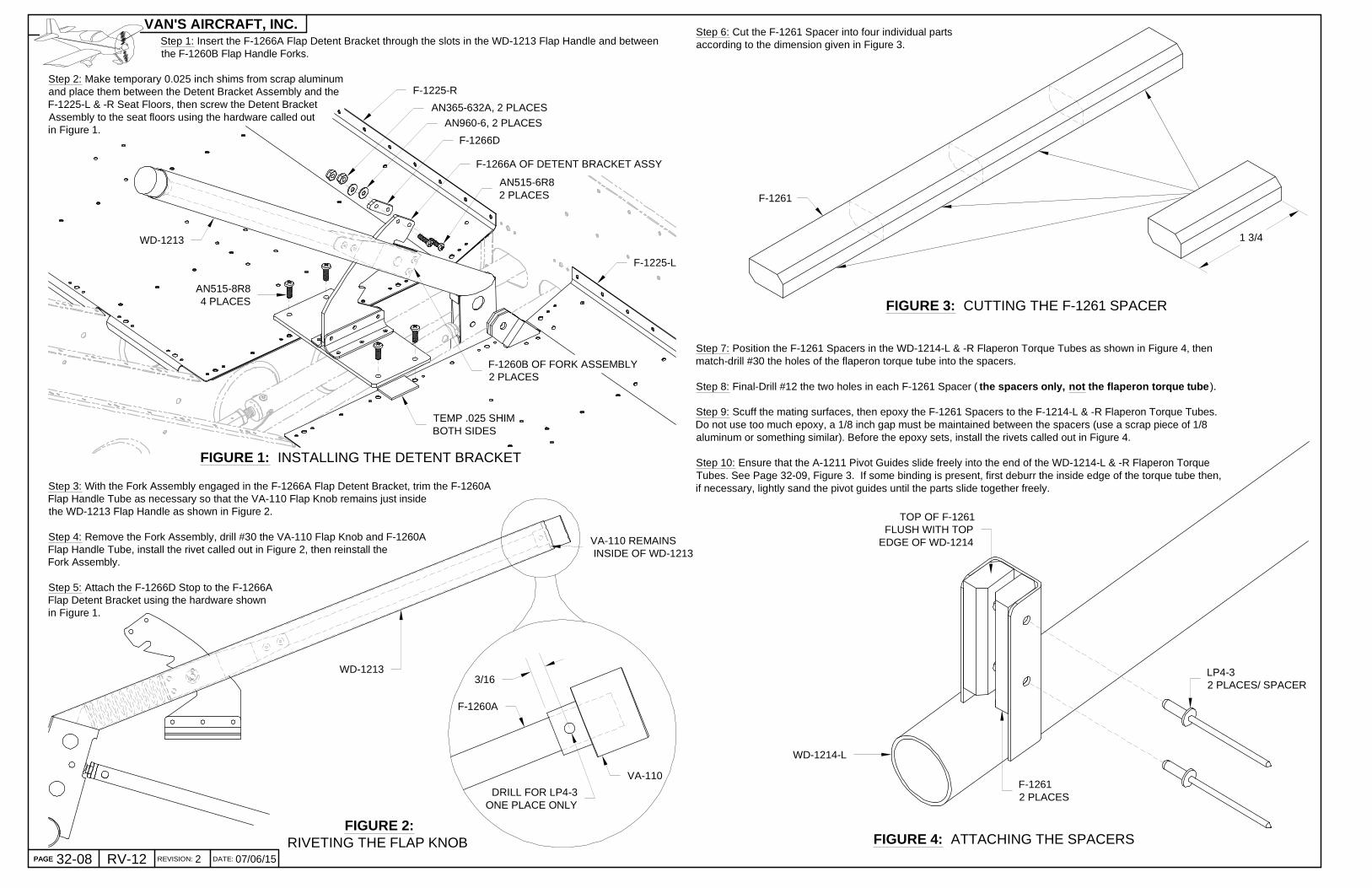
Step 1: Insert the F-1266A Flap Detent Bracket through the slots in the WD-1213 Flap Handle and between the F-1260B Flap Handle Forks.
Step 2: Make temporary 0.025 inch shims from scrap aluminumand place them between the Detent Bracket Assembly and theF-1225-L & -R Seat Floors, then screw the Detent BracketAssembly to the seat floors using the hardware called outin Figure 1.
FIGURE 2:RIVETING THE FLAP KNOB
FIGURE 1: INSTALLING THE DETENT BRACKET
F-1266A OF DETENT BRACKET ASSY
TEMP .025 SHIMBOTH SIDES
AN515-8R84 PLACES
F-1225-L
F-1225-R
F-1260B OF FORK ASSEMBLY2 PLACES
WD-1213
Step 3: With the Fork Assembly engaged in the F-1266A Flap Detent Bracket, trim the F-1260AFlap Handle Tube as necessary so that the VA-110 Flap Knob remains just insidethe WD-1213 Flap Handle as shown in Figure 2.
Step 4: Remove the Fork Assembly, drill #30 the VA-110 Flap Knob and F-1260AFlap Handle Tube, install the rivet called out in Figure 2, then reinstall theFork Assembly.
Step 5: Attach the F-1266D Stop to the F-1266AFlap Detent Bracket using the hardware shownin Figure 1.
DRILL FOR LP4-3ONE PLACE ONLY
VA-110
F-1260A
VA-110 REMAINS INSIDE OF WD-1213
3/16
1 3/4
F-1261
LP4-32 PLACES/ SPACER
WD-1214-L
F-12612 PLACES
TOP OF F-1261FLUSH WITH TOP
EDGE OF WD-1214
Step 6: Cut the F-1261 Spacer into four individual partsaccording to the dimension given in Figure 3.
Step 7: Position the F-1261 Spacers in the WD-1214-L & -R Flaperon Torque Tubes as shown in Figure 4, thenmatch-drill #30 the holes of the flaperon torque tube into the spacers.
Step 8: Final-Drill #12 the two holes in each F-1261 Spacer ( the spacers only, not the flaperon torque tube ).
Step 9: Scuff the mating surfaces, then epoxy the F-1261 Spacers to the F-1214-L & -R Flaperon Torque Tubes.Do not use too much epoxy, a 1/8 inch gap must be maintained between the spacers (use a scrap piece of 1/8aluminum or something similar). Before the epoxy sets, install the rivets called out in Figure 4.
Step 10: Ensure that the A-1211 Pivot Guides slide freely into the end of the WD-1214-L & -R Flaperon TorqueTubes. See Page 32-09, Figure 3. If some binding is present, first deburr the inside edge of the torque tube then,if necessary, lightly sand the pivot guides until the parts slide together freely.
FIGURE 3: CUTTING THE F-1261 SPACER
FIGURE 4: ATTACHING THE SPACERS
WD-1213
F-1266D
AN365-632A, 2 PLACES
AN515-6R82 PLACES
AN960-6, 2 PLACES
PAGE REVISION: DATE:
VAN'S AIRCRAFT, INC.
PAGE

32-0907/06/15 2 RV-12
Step 1: From the 12 inch length of MS21266-1N Nylon Grommet supplied,cut two 3-11/16 lengths and install them around the edges of the holes inthe F-1273-L & -R Baggage Corner Skins as shown in Figure 1.
Step 2: Slide the WD-1214-L & -R Flaperon Torque Tubesthrough the holes in the F-1273-L & -R Baggage CornerSkins and between the brackets of the WD-1215L & -RFlaperon Torque Arms as shown in Figure 1.
FIGURE 1: INSTALLING THE FLAPERON TORQUE TUBE
WD-1215-L
WD-1215-R
WD-1214-L
WD-1214-R
F-1273-L
MS21266-1N WD-1214-L
F-1273-L
Step 3: Place the WD-1213Flaperon Handle in the lowest(flaps up) detent in the F-1266AFlaperon Detent Bracket, thenuse the bolt shown in Figure 2to temporarily lock the flaperoncontrol system in the neutralposition. Pass the bolt throughthe holes in both F-1219Flaperon Mixer Arms andthrough the holes in theF-1263A & B FlaperonMixer Bellcranks.
FIGURE 2: LOCKINGTHE FLAPERON
CONTROL SYSTEM
F-1266AWD-1213
AN3-21A
F-1263A
F-12192 PLACES
Step 4: Install the wings. During installation, use axle grease to lubricate the A-1211 Pivot Guides and A-1207-L & -R ActuationBrackets. The pivot guides slide into the WD-1214-L & -R Flaperon Torque Tubes and the actuation brackets slide between theF-1261 Spacers as shown in Figure 3.
FIGURE 3: LOCKING THE FLAPERON CONTROL SYSTEM
A-1211
A-1207-L
WD-1214-L
F-12612 PLACES
PAGEREVISION:DATE:
VAN'S AIRCRAFT, INC.

32-10 08/12/131RV-12
FIGURE 2: DRILLING THEFLAPERON TORQUE TUBES
Step 9: Reinstall the WD-1215-L & -R FlaperonTorque Arms (Page 32-06, Figure 3), thenattach the WD-1214-L & -R FlaperonTorque Tubes using the hardwarecalled out in Figure 3.
FIGURE 4: SEPARATING THE RUDDER CABLE LINKS
Step 2: Flush the ends of the WD-1214-L & -R Flaperon Torque Tubes with the brackets on the WD-1215-L & -R FlaperonTorque Arms as shown in Figure 2. If the A-1207-L & -R Actuation Brackets on the flaperons (see Page 32-09, Figure 3) forcethe flaperon torque tubes to extend beyond the brackets, trim the actuation brackets until the flaperon torque tubes are flush.
Step 3: Insert a temporary 0.063 spacer between the WD-1214-L & -R Flaperon Torque Tubes and the WD-1215-L & -RFlaperon Torque Arms as shown in Figure 2, then clamp the parts together.
Step 4: Match-Drill #30 (use a 12 inch extension drill bit) the two holes of the WD-1215-L & -R Flaperon Torque Arms into theWD-1214-L & -R Flaperon Torque Tubes (one side only, and cleco the first hole before match-drilling the second).
Step 5: Remove the wings, then removethe WD-1215-L & -R Flaperon TorqueArms and WD-1214-L & -R FlaperonTorque Tubes from the fuselage.
Step 6: On a work bench andwith the 0.063 spacers inplace, cleco together theWD-1215-L & -R FlaperonTorque Arms andWD-1214-L & -R FlaperonTorque Tubes using thepreviously match-drilledholes. Reapply the clamps.
Step 7: Match-Drill #30 the holes in the otherside of the WD-1215-L & -R Flaperon TorqueArms into the WD-1214-L & -R FlaperonTorque Tubes.
Step 8: Final-Drill #12 all the way through bothsets of holes (insert a bolt after final-drilling thefirst set) in the WD-1215-L & -R FlaperonTorque Arms and WD-1214-L & -R FlaperonTorque Tubes.
END OF TUBEFLUSH WITH END
OF BRACKETS
WD-1214-L
WD-1215-L
TEMPORARY.063 SPACER
FIGURE 3: SECURING THE FLAPERON TORQUE TUBES
AN3-14A2 PLACES
AN960-102 PLACES
AN365-10322 PLACES
WD-1215-L
WD-1214-L
WD-1215-R
MATCH-DRILL
Step 10: Separate the F-1258 RudderCable Links by removing the shadedareas shown in Figure 4.
F-1258
PAGE REVISION: DATE:
VAN'S AIRCRAFT, INC.
PAGE
FIGURE 1: SHIM & CLAMPTHE TRAILING EDGES
Step 1: Use .125 thick shims and clamps to droop down both the left andright Flaperons as shown in Figure 1.
FLAPERONDROOPEDDOWN
.125 THICK SHIM,2 PLACES
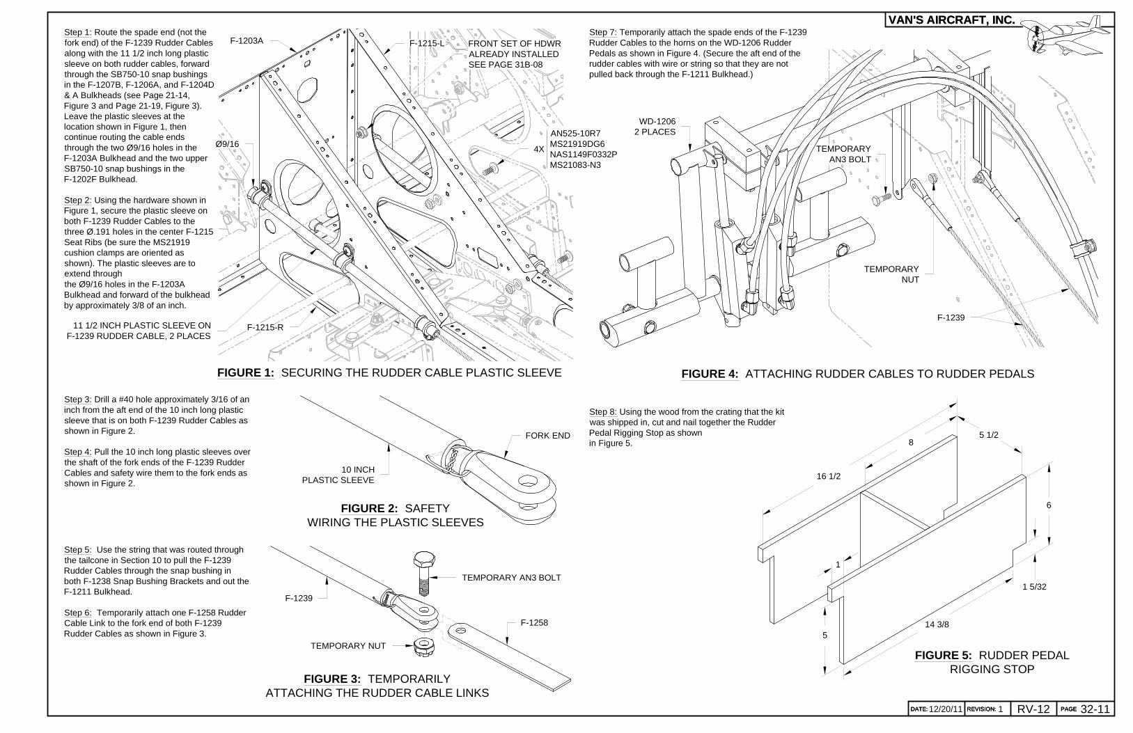
Step 1: Route the spade end (not thefork end) of the F-1239 Rudder Cablesalong with the 11 1/2 inch long plasticsleeve on both rudder cables, forwardthrough the SB750-10 snap bushingsin the F-1207B, F-1206A, and F-1204D& A Bulkheads (see Page 21-14,Figure 3 and Page 21-19, Figure 3).Leave the plastic sleeves at thelocation shown in Figure 1, thencontinue routing the cable endsthrough the two Ø9/16 holes in theF-1203A Bulkhead and the two upperSB750-10 snap bushings in theF-1202F Bulkhead.
Step 2: Using the hardware shown inFigure 1, secure the plastic sleeve onboth F-1239 Rudder Cables to thethree Ø.191 holes in the center F-1215Seat Ribs (be sure the MS21919cushion clamps are oriented asshown). The plastic sleeves are toextend throughthe Ø9/16 holes in the F-1203ABulkhead and forward of the bulkheadby approximately 3/8 of an inch.
FIGURE 1: SECURING THE RUDDER CABLE PLASTIC SLEEVE
4XØ9/16
11 1/2 INCH PLASTIC SLEEVE ONF-1239 RUDDER CABLE, 2 PLACES
F-1215-R
F-1215-LF-1203A
FIGURE 3: TEMPORARILYATTACHING THE RUDDER CABLE LINKS
Step 5: Use the string that was routed throughthe tailcone in Section 10 to pull the F-1239Rudder Cables through the snap bushing inboth F-1238 Snap Bushing Brackets and out theF-1211 Bulkhead.
Step 6: Temporarily attach one F-1258 RudderCable Link to the fork end of both F-1239Rudder Cables as shown in Figure 3.
Step 7: Temporarily attach the spade ends of the F-1239Rudder Cables to the horns on the WD-1206 RudderPedals as shown in Figure 4. (Secure the aft end of therudder cables with wire or string so that they are notpulled back through the F-1211 Bulkhead.)
TEMPORARYNUT
WD-12062 PLACES
F-1239
TEMPORARYAN3 BOLT
FIGURE 4: ATTACHING RUDDER CABLES TO RUDDER PEDALS
FIGURE 2: SAFETYWIRING THE PLASTIC SLEEVES
FORK END
10 INCHPLASTIC SLEEVE
Step 3: Drill a #40 hole approximately 3/16 of aninch from the aft end of the 10 inch long plasticsleeve that is on both F-1239 Rudder Cables asshown in Figure 2.
Step 4: Pull the 10 inch long plastic sleeves overthe shaft of the fork ends of the F-1239 RudderCables and safety wire them to the fork ends asshown in Figure 2.
TEMPORARY AN3 BOLT
TEMPORARY NUT
F-1258
F-1239
PAGEREVISION:DATE:
VAN'S AIRCRAFT, INC.
DATE: 32-11112/20/11 REVISION: RV-12 PAGE
1
5
Step 8: Using the wood from the crating that the kitwas shipped in, cut and nail together the RudderPedal Rigging Stop as shownin Figure 5. 8
5 1/2
6
16 1/2
14 3/8
1 5/32
FIGURE 5: RUDDER PEDALRIGGING STOP
FRONT SET OF HDWRALREADY INSTALLEDSEE PAGE 31B-08
AN525-10R7MS21919DG6NAS1149F0332PMS21083-N3
PAGEREVISION:DATE:
VAN'S AIRCRAFT, INC.
32-12 09/28/121RV-12
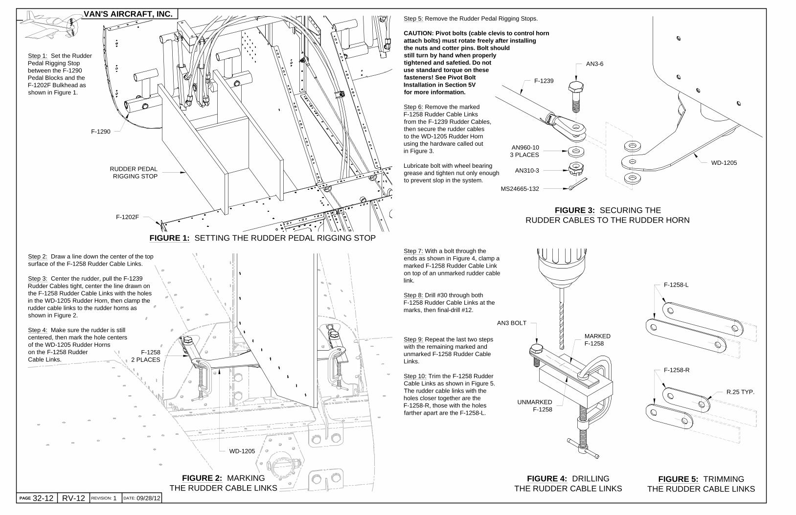
Step 5: Remove the Rudder Pedal Rigging Stops.
CAUTION: Pivot bolts (cable clevis to control hornattach bolts) must rotate freely after installingthe nuts and cotter pins. Bolt shouldstill turn by hand when properlytightened and safetied. Do notuse standard torque on thesefasteners! See Pivot BoltInstallation in Section 5Vfor more information.
Step 6: Remove the markedF-1258 Rudder Cable Linksfrom the F-1239 Rudder Cables,then secure the rudder cablesto the WD-1205 Rudder Hornusing the hardware called outin Figure 3.
Lubricate bolt with wheel bearinggrease and tighten nut only enoughto prevent slop in the system.
FIGURE 3: SECURING THERUDDER CABLES TO THE RUDDER HORN
Step 1: Set the RudderPedal Rigging Stopbetween the F-1290Pedal Blocks and theF-1202F Bulkhead asshown in Figure 1.
FIGURE 1: SETTING THE RUDDER PEDAL RIGGING STOP
FIGURE 2: MARKINGTHE RUDDER CABLE LINKS
Step 2: Draw a line down the center of the topsurface of the F-1258 Rudder Cable Links.
Step 3: Center the rudder, pull the F-1239Rudder Cables tight, center the line drawn onthe F-1258 Rudder Cable Links with the holesin the WD-1205 Rudder Horn, then clamp therudder cable links to the rudder horns asshown in Figure 2.
Step 4: Make sure the rudder is stillcentered, then mark the hole centersof the WD-1205 Rudder Hornson the F-1258 RudderCable Links.
F-12582 PLACES
WD-1205
FIGURE 4: DRILLINGTHE RUDDER CABLE LINKS
FIGURE 5: TRIMMINGTHE RUDDER CABLE LINKS
R.25 TYP.
F-1258-L
Step 7: With a bolt through theends as shown in Figure 4, clamp amarked F-1258 Rudder Cable Linkon top of an unmarked rudder cablelink.
Step 8: Drill #30 through bothF-1258 Rudder Cable Links at themarks, then final-drill #12.
Step 9: Repeat the last two stepswith the remaining marked andunmarked F-1258 Rudder CableLinks.
Step 10: Trim the F-1258 RudderCable Links as shown in Figure 5.The rudder cable links with theholes closer together are theF-1258-R, those with the holesfarther apart are the F-1258-L.
F-1258-R
AN3-6
AN960-103 PLACES
AN310-3
MS24665-132
WD-1205
F-1239
AN3 BOLT
MARKEDF-1258
UNMARKEDF-1258
RUDDER PEDALRIGGING STOP
F-1290
F-1202F
PAGE REVISION: DATE:
VAN'S AIRCRAFT, INC.
PAGE

32-1309/28/12 1 RV-12
See Page 32-12 CAUTION .
Step 1: Secure the F-1239 Rudder Cables to the horns of theWD-1206 Rudder Pedals using the F-1258-L & -R RudderCable links and the hardware called out in Figure 1.
Lubricate bolt with wheel bearing grease andtighten nut only enough to prevent slopin the system.
FIGURE 2: INSTALLING BUSHING FIGURE 4: CONNECTING THE STABILATOR CABLES
FIGURE 1: SECURING THE RUDDER CABLES
MS24665-1322 PLACES
AN310-32 PLACES
AN960-104 PLACES
F-1258-L2 PLACES
AN3-52 PLACES
F-1258-R2 PLACES
BUSHING
WD-1210
MS24665-132
AN310-3
F-1250-L
AN960-102 PLACES
AN3-6
F-1247A
MS24566-4B2 PLACES
F-1250-R
AN4-14A
AN960-416
AN960-416L
AN364-428
Step 3: Secure the F-1247A ForwardStabilator Cables to the WD-1210Control Column using the hardwarecalled out in Figure 3.
See Step 1 for lubrication andtightening.
Step 4: Route the aft end of bothF-1247A Forward Stabilator Cablesover the bushing and through thehole in the F-1220B Aft Intercostalas shown in Figure 3.
Step 5: Install the two pulleysshown in Figure 3 using thehardware called out. Be surethe F-1247A Forward StabilatorCables are captured betweenthe bushing and the pulleys.
FIGURE 3: INSTALLING PULLEYS
F-1220B
Step 2: Install the bushing shown inFigure 2 between the F-1250-L & -RPulley Brackets using the hardwarecalled out.
AN3-13A
BUSHING AL .197 X .313 X .968
AN960-10
MS21083-N3
F-1250-L
F-1250-R
Step 6: Use the string that was routed throughthe tailcone in Section 10 to pull the F-1247BAft Stabilator Cables through theholes in the F-1211 Bulkhead.Secure the ends of the aftstabilator cables to theWD-1207 and WD-1208Stabilator Horns usingthe hardware called outin Figure 4.
See Step 1 for lubricationand tightening.
AN3-6
AN960-10L2 PLACES
AN960-10
AN310-3
MS24665-132
WD-1208
WD-1207
F-1247B2 PLACES
F-12392 PLACES
WD-12062 PLACES
PAGEREVISION:DATE:
VAN'S AIRCRAFT, INC.

FIGURE 2: CONNECTING THE STABILATOR CABLES
FIGURE 1: ROUTING THE STABILATOR CABLES
FIGURE 3: LOCKING THE BARRELS
F-1247B FROM TOPSTABILATOR HORN
F-1247B FROM BOTTOMSTABILATOR HORN
F-1247A FROMRIGHT PULLEY
F-1204A
F-1204D
F-1206A
F-1207B
WIRE TOOL (MADE FROMWELDING WIRE, COATHANGER WIRE, ETC.)
F-1247A
MS21251-B5SBARREL
F-1247B
MS21256-1LOCK CLIP
ALIGN V-NOTCH IN BARREL WITHGROOVE IN CABLE END
GROOVE AROUNDBARREL TOWARD
AFT (DENOTESLEFT HAND THREAD)
PAGE REVISION: DATE:
VAN'S AIRCRAFT, INC.
09/29/14PAGE 32-14 RV-12
NOTE: A cabl e tension meter is required to accuratel y set the cable tension.
Step 1: Route the F-1247B Aft Stabilator Cables forward through theholes in the F-1207B and F-1206A Bulkheads; see Fig. 1. The cablefrom the top stabilator horn passes through the upper hole.
Step 2: Route the F-1247A Forward Stabilator Cables aft through theholes in the F-1204A & D Bulkheads shown in Figure 1. The cablefrom the right pulley passes through the upper hole.
Step 3: Reach through the access holes in the bottom of the fuselageand connect the F-1247A & B Stabilator Control Cables as shown inFigure 2. A wire tool can be made that is inserted into the holes in thecable ends. This will hold them stationary as the barrel is rotated.
Step 4: Place a small weight on the stabilator to hold it trailing edge down.Remove the slack from the upper cable by tightening the upper(outboard) turnbuckle until the control stick and stabilator just start to liftoff the stops at about the same time when the stick is moved aft.
Remove the slack from the other cable by adjusting the lower(inboard) turnbuckle. Check the entire length of the cables toensure they are free from interference, are properly aligned inthe pulleys, and do not touch each other. Pull the stick aft tomake sure that the stabilator trailing edge moves up.
NOTE: The F-1227 Seat Ramp Cover must be installedprior to adjusting the cable tension.
Step 5: Install the F-1227 Seat Ramp Cover (Page 33-02,Figure 4). If the screw holes for the F-1233 Control Column MountBrackets (Page 21-10, Figure 1) do not align with the cover, a lightupward pull on the stick will correct the misalignment until the screwsare inserted and tightened.
NOTE: Cable tension will change significantly with changingtemperature. The cable tensions given below are for an aircraftinside a 70 °F hanger.
Step 6: Position one of the WD-1212 Control Sticks so that the top endis 10 inches from the lower face of the F-1202T Instrument Panel Left orF-1202U Instrument Panel Right (Page 29-07, Figure 2). Secure thecontrol stick in place using a spring clamp to attach it to a 41" long stickbridged between and clamped to the upper longerons.
Check the cable tension just aft of the F-1207B Baggage Bulkhead usinga calibrated cable tension meter making sure the control stick is correctlypositioned.
Adjust turnbuckles an equal number of turns each to achieve 35-45 lbs oftension with the groove in the cable ends aligned with a V-notch in eachturnbuckle barrel as shown in Figure 3. This tension will prevent thecables from "slapping" against the tailcone bulkheads when the controlsticks are moved suddenly and repeatedly forward then aft.
Step 7: Remove the clamp and stick from the control stick and theweight from the stabilator.
Move the control stick between the forward and aft pitch stops. Thestabilator should reach its travel stops just before the correspondingcontrol stick stops are reached.
Step 7 (continued): If not, adjust the turnbuckles an equal and oppositenumber of turns until this is achieved. (Example: If the stabilator reaches itsT.E. up stop too soon loosen the upper turnbuckle and tighten the lowerturnbuckle. This will lengthen the upper cable and shorten the lower cable).After making adjustments repeat step 6 to reconfirm proper cable tension.
Step 8: Once the proper tension is achieved, and no more than three threadsare exposed from the ends of the barrels, align the V-notch in the ends of thebarrel with the groove in the cable ends and then insert the lock clips as shownin Figure 3. The hook end of the lock clips are inserted into the hole in thecenter of the barrel and must be completely pressed in untilthe hook springs open inside the barrel.
3