QRH REV 29.0 - TOTAL JUN 21 Kg
238
FLEET 42-400/500 REV 29.0 - TOTAL JUN 21 Kg QRH Quick Reference Handbook The content of this document is the property of AVIONS DE TRANSPORT REGIONAL. It is supplied in confidence and commercial security on its content must be maintained. It must not be used for any purpose other than that for which it is supplied, nor may information contained in it be disclosed to unauthorized persons. It must not reproduced in whole or in part without permission in writing from the owners of the copyright. ©2020. All rights reserved PK1_QRH_45_L_SI_full_Rev29.0
Transcript of QRH REV 29.0 - TOTAL JUN 21 Kg

FLEET42-400/500
REV 29.0 - TOTALJUN 21
Kg
QRH Quick Reference Handbook
The content of this document is the property of AVIONS DETRANSPORT REGIONAL. It is supplied in confidence andcommercial security on its content must be maintained. It must not beused for any purpose other than that for which it is supplied, nor mayinformation contained in it be disclosed to unauthorized persons. Itmust not reproduced in whole or in part without permission in writingfrom the owners of the copyright. ©2020. All rights reserved
PK1_QRH_45_L_SI_full_Rev29.0


LIST OF EFFECTIVE OPERATIONSENGINEERING BULLETINS
Identification Title
OEB 25 Issue 1 Propeller Blade Pitch Change Mechanism Damage
OEB 27 Issue 1 Uncommanded Autofeather
OEB 28 Issue 1 MFC 1B and/or MFC 2B Fault
OEB 30 Issue 1 Spurious Glide Slope Capture
OEB 32 Issue 1 ENGINE FIRE WARNING
OEB 36 Issue 1 Bank angle limitation in Severe Icing Conditions
OEB 42 Issue 1 Static Inverter Double Loss
OEB 43 Issue 1 Cockpit Voice Recorder
OEB 49 Issue 1 Temporary ENG 1(2) OIL LO PR procedure
LIST OF EFFECTIVE OEBs
OEBOEB
PK / 45 Page n°01
PAGE
INTENTIONALLY
LEFT BLANK
LIST OF EFFECTIVE OEBs
OEBOEB
PK / 45 Page n°02

GENERAL DESCRIPTION_ad23bea2-0586-49a0-b385-63974656a280 0.5
ALLAn Operations Engineering Bulletin (OEB) is issued to rapidly inform operators of anydeviations from initial design objectives that have a significant operational impact. AnOEB provides the operators with technical information and temporary operationalprocedures that address these deviations.ATR strongly recommends that all Operators rapidly apply the OEB corrective actionsas soon as they become available.OEB CONTENT AND MANAGEMENTAn OEB:
- Is temporary and usually focuses on one operational subject.- Is included in the OEB section of both the FCOM and QRH. The procedural
part of OEB (OEB PROC) is provided in the OEB section of the QRH to ensureeasy access by flight crew.
- Remains applicable until the appropriate corrective actions are completed.- Contains information that is recommended by ATR. It is not approved by
Airworthiness Authorities.If the procedures contained in the OEB differ from the procedures in the AFM, the AFMremains the reference.NoteFollowing the installation of the OEB corrective modification/Service Bulletins (SB): ifan Operator re-installs any spare equipment for which there was an associated OEB,it is the Operator’s responsibility to ensure that the OEB be applied again for theapplicable aircraft.
OEB IN THE QRHEach FCOM OEB has an associated “OEB PROC” in the OEB section of the QRH, thatincludes:
- The title of the OEB PROC,- The OEB operational procedure(s) that the flight crew must apply.
DISTRIBUTIONOEB’s are distributed to all FCOM holders and to others who need advice of changesto operational information. The Operator shall provide flight crews with the content ofthe OEB’s without delay.QRH LIST OF EFFECTIVE OEB’sThe List of Effective Operations Engineering Bulletins (LOEB) enables flight crews toreview all the Operations Engineering Bulletins (OEB’s) that are applicable to the fleet.Each time an OEB’s is issued or revised, the LOEB is updated.
Identification Title
OEB’s 12 Issue 01 Cockpit Voice Recorder
The QRH LOEB consists of:- The "Identification" field which identifies the OEB with its Identification and
issue Number.- The "Title" field provides the OEB title.
REVIEW OF THE OEB’sIn accordance with the Standard Operating Procedures, and before each flight, theflight crew must review all OEB’s that are applicable to their aircraft. If the OEB’sconditions are applicable, the flight crew must apply the operational procedure(s) in theOEB’s section of the QRH.
OPERATIONS ENGINEERINGBULLETINS OEB /
PK / 45 Page n°03

Propeller Blade Pitch Change Mechanism Damage_e6f4d1ef-063c-441c-9bfc-b0c9dd6a2e60 REV 7.0
ALLProcedure
Even if all the reported cases occurred on engine 2, the recommended procedure aimsat confirming/identifying the affected engine first and then to shut it down.The identification of the affected engine can be performed thanks to engineparameters fluctuations monitoring or alerts displayed on one side.However, the identification may be less obvious depending on the damages and thelevel of vibrations. In this case, the following procedure will request to perform PowerLever and Propeller speed variations on one engine at a time and to assess whichengine makes vibrations change (increase or decrease).In any case, every vibration occurrence is to be reported to maintenance.If the power levers has to be reduced to flight idle position during descent at highspeed (close to VMO), it is recommended to perform a smooth and progressive powerlevers reduction.IN CASE OF SUDDEN AND HIGH VIBRATIONS
▶ ICING CONDITIONS................................... ...................................CHECKUnbalanced blade icing may also generate propeller vibrations.In this case Refer to AFM - Procedure for Icing Conditions, or Refer to AFM -QRH SEVERE ICING procedure.
▶ ENG PARAMETERS................................... ................................... CHECKCheck for any fluctuations of power plant parameters that may indicate theaffected engine, mainly TQ and NP. Check also for transient or steady alerts(PEC, ACW faults or any other alerts) that may be associated with power plantvibrations and indicate the affected engine.
If affected engine cannot be identified via engine parameters, flight crew shouldmove one PL at a time: it may help to determine the affected side, as the vibrationslevel and frequency may change with PL position.■ IF AFFECTED ENGINE IS IDENTIFIED▶ PL (affected eng).............................................................................. FI▶ CL (affected eng)........................ ........................ FTR THEN FUEL S.O.LAND ASAP▶ SINGLE ENG OPERATION procedure..........................................APPLY
■ IF AFFECTED ENGINE CANNOT BE IDENTIFIED▶ PL 2................................................................................................ FI▶ CL 2.............................................. .............................................. FTR■ IF VIBRATIONS SIGNIFICANTLY CHANGE
Engine 2 failure is suspected and should be shut down.▶ CL 2....................................... ....................................... FUEL S.O.LAND ASAP▶ SINGLE ENG OPERATION procedure.................. .................. APPLY
■ IF VIBRATIONS PERSISTRestore engine 2 and same check repeated on engine 1.▶ CL 2......................................................................................AUTO▶ PL 2................................................................................AS RQRD▶ PL 1............................................. ............................................. FI▶ CL 1........................................... ........................................... FTR■ IF VIBRATIONS SIGNIFICANTLY CHANGE
Engine 1 failure is suspected and should be shut down.▶ CL 1..........................................................................FUEL S.O.LAND ASAP▶ SINGLE ENG OPERATION procedure................................APPLY
END OF OEB 25
OPERATIONS ENGINEERINGBULLETINS OEB 25/1
PK / 45 OEB 25 Page n°04
Uncommanded Autofeather_21f12523-3ff7-4ee4-8f05-fecbd32f16c7 4.1
ALLProcedure
TAKEOFF NORMAL PROCEDUREAs a normal practice, at takeoff the ATPCS must be checked armed andannounced Refer to FCOM - Takeoff. If it is not armed while both power levers arein the notch, or in the case of intermittent arming / disarming of the ATPCS, thetakeoff has to be interrupted, as for any other anomaly intervening during thetakeoff run.
ANY LOSS OF NP AND TQ MUST BE DEALT AS AN ENGINEFAILURE
● AT TAKEOFF▶ ENG 1(2) FLAME OUT AT TAKE OFF procedure............. ............. APPLY
● AT ANY OTHER PHASE OF FLIGHT▶ PL (affected eng).............................................................................. FI▶ CL (affected eng)........................ ........................ FTR THEN FUEL S.O.LAND ASAP▶ SINGLE ENG OPERATION procedure..........................................APPLY
END OF OEB 27
OPERATIONS ENGINEERINGBULLETINS OEB 27/1
PK / 45 OEB 27 Page n°05
MFC 1B and-or MFC 2B Fault_cb0a75d6-9030-4a27-b36e-a994e40b6873 7.1
ALLProcedure
● In flight■ If MFC 1B+2B FAULT▶ MFC 1B.......................................... ..........................................RESET
NoteRESET of each MFC must be performed one by one.
▶ MFC 2B.......................................... ..........................................RESET■ If one MFC module recovered▶ MFC (affected module) procedure............................................APPLY
■ If MFC 1B + 2B FAULT persist▶ MFC 1B + 2B FAULT procedure....................... ....................... APPLY
● For landingNosewheel Steering is inoperative. Use rudder, differential braking andreverse which are still operative.
■ If MFC 1B (2B) FAULT▶ MFC (affected module)............................... ............................... RESET■ If erroneous alert (Without Master Caution or Warning) persists▶ MFC (operative module)............................ ............................ RESET
■ If MFC 1B (2B) FAULT persists▶ MFC (affected module) procedure............................................APPLY
END OF OEB 28
OPERATIONS ENGINEERINGBULLETINS OEB 28/1
PK / 45 OEB 28 Page n°06

Spurious Glide Slope Capture_160c3390-d49d-45a1-a82d-2b87d8b11f59 2.0
ALLProcedure
It is reminded to the flight crew that the GS interception must always be cross-checkedby comparing altitude/distance between aircraft actual position and flight pathpublished on the approach charts.■ After APP mode arming and when LOC*▶ G/S deviations.............................. .............................. CLOSELY MONITOR▶ FAP ALT/DIST................. ................. X CHECK WITH APPROACH CHARTSNoteThe flight crew should be prepared to take-over control in the case of a spuriousG/S*, pitch movement or any flight path deviation.
■ In the case of a spurious G/S*▶ AP .................................................. ..................................................OFF▶ FD ................................................ ................................................ STBY▶ FLIGHT PATH....................................... ....................................... ADJUST■ When back on the appropriate flight path▶ AFCS ............................................. ............................................. SET▶ AP ........................................... ........................................... AS RQRD
END OF OEB 30
OPERATIONS ENGINEERINGBULLETINS OEB 30/1
PK / 45 OEB 30 Page n°07

ENGINE FIRE Warning_991cad58-ad82-43cb-97a9-097088b275a6 4.1
ALLProcedure
Procedure in case of ENG FIRE warning, in landing configuration, with PL at FIFollowing procedure has to be applied only in the following conditions:
- During steep slope descent at low speed (around 130 kt to final approachspeed), and
- In landing configuration (Gear Down, Flaps 30 or 35) set at high altitude, and- Power Levers durably maintained at Flight Idle.
■ If ENG 1(2) FIRE warning during steep slope descent in landing configurationwith PL at FI▶ PL 1+2 ................................................................ADJUST ABOVE 10% TQTQ increase improves the nacelle ventilation
■ If ENG 1(2) FIRE warning stops before 10 s▶ PL 1+2 ........................................................MAINTAIN ABOVE 10% TQLAND ASAP
■ If ENG 1(2) FIRE warning persists after 10 s▶ ENG 1(2) FIRE OR SEVERE MECHANICAL DAMAGE IN FLIGHT
procedure........................................ ........................................ .APPLY▶ MAINTENANCE REPORT............................. .............................PERFORM
NoteNacelles must be inspected in accordance with the appropriate maintenanceprocedures.
END OF OEB 32
OPERATIONS ENGINEERINGBULLETINS OEB 32/1
PK / 45 OEB 32 Page n°08
Bank angle limitation in Severe Icing Conditions_fbbd16d8-a229-430d-9f1d-3447d5a07a3e 3.2
ALLProcedure
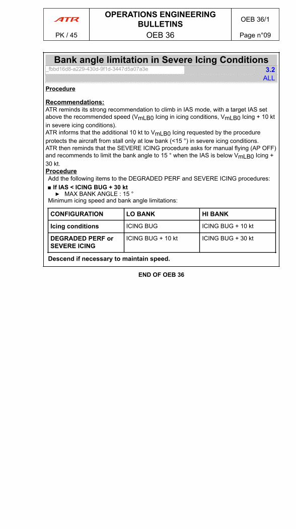
Recommendations:ATR reminds its strong recommendation to climb in IAS mode, with a target IAS setabove the recommended speed (VmLB0 Icing in icing conditions, VmLB0 Icing + 10 ktin severe icing conditions).ATR informs that the additional 10 kt to VmLB0 Icing requested by the procedureprotects the aircraft from stall only at low bank (<15 °) in severe icing conditions.ATR then reminds that the SEVERE ICING procedure asks for manual flying (AP OFF)and recommends to limit the bank angle to 15 ° when the IAS is below VmLB0 Icing +30 kt.ProcedureAdd the following items to the DEGRADED PERF and SEVERE ICING procedures:■ If IAS < ICING BUG + 30 kt▶ MAX BANK ANGLE : 15 °
Minimum icing speed and bank angle limitations:
CONFIGURATION LO BANK HI BANK
Icing conditions ICING BUG ICING BUG + 10 kt
DEGRADED PERF orSEVERE ICING
ICING BUG + 10 kt ICING BUG + 30 kt
Descend if necessary to maintain speed.
END OF OEB 36
OPERATIONS ENGINEERINGBULLETINS OEB 36/1
PK / 45 OEB 36 Page n°09
Static Inverter Double Loss_6a722135-cde2-48b8-af47-269f36045394 1.0
ALLProcedure
NoteATR recommends application of modification 5546 which facilitates identification ofinvolved C/B by means of orange caps.
STATIC INVERTER DOUBLE LOSS▶ BTC .................................................. .................................................. ISOL▶ C/B 3XA INV 1 127VU position AB3........................................................RESET▶ C/B 10XA INV 2 124VU position AB4......................................................RESET▶ KEEP FLYING WITH BTC ................................... ................................... ISOL■ If no static inverter recovered▶ C/B 3XD 26VAC STBY BUS 122VU position Q39....................................OFF▶ C/B 4XD 115VAC STBY BUS 122VU position Q40 ..................................OFF▶ C/B 3XA INV 1 127VU position AB3......................... ......................... RESET▶ C/B 10XA INV 2 124VU position AB4........................ ........................ RESET▶ BTC ................................................. ................................................. ON
END OF OEB 42
OPERATIONS ENGINEERINGBULLETINS OEB 42/1
PK / 45 OEB 42 Page n°10

Cockpit Voice Recorder_56636456-575e-4d78-b76e-ba55c0299b1f 3.0
0665Procedure
The flight crew must use boomsets on ground and in flight below FL 100.
END OF OEB 43
OPERATIONS ENGINEERINGBULLETINS OEB 43/1
PK / 45 OEB 43 Page n°11
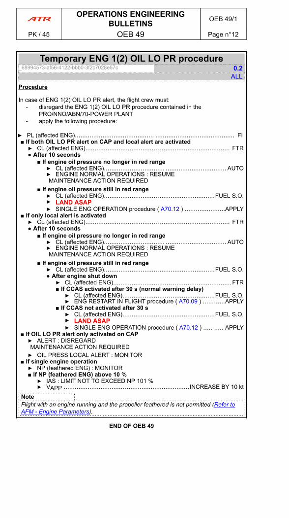
Temporary ENG 1(2) OIL LO PR procedure_68994573-af56-4122-bbb0-3f2c7028e57c 0.2
ALLProcedure
In case of ENG 1(2) OIL LO PR alert, the flight crew must:- disregard the ENG 1(2) OIL LO PR procedure contained in the
PRO/NNO/ABN/70-POWER PLANT- apply the following procedure:
▶ PL (affected ENG)........................................... ........................................... FI■ If both OIL LO PR alert on CAP and local alert are activated▶ CL (affected ENG)....................................... ....................................... FTR● After 10 seconds
■ If engine oil pressure no longer in red range▶ CL (affected ENG)................................. ................................. AUTO▶ ENGINE NORMAL OPERATIONS : RESUMEMAINTENANCE ACTION REQUIRED
■ If engine oil pressure still in red range▶ CL (affected ENG)............................................................FUEL S.O.▶ LAND ASAP▶ SINGLE ENG OPERATION procedure ( A70.12 ) ......................APPLY
■ If only local alert is activated▶ CL (affected ENG)....................................... ....................................... FTR● After 10 seconds
■ If engine oil pressure no longer in red range▶ CL (affected ENG)................................. ................................. AUTO▶ ENGINE NORMAL OPERATIONS : RESUMEMAINTENANCE ACTION REQUIRED
■ If engine oil pressure still in red range▶ CL (affected ENG)............................................................FUEL S.O.● After engine shut down▶ CL (affected ENG)................................ ................................FTR■ If CCAS activated after 30 s (normal warning delay)▶ CL (affected ENG)..................................................FUEL S.O.▶ ENG RESTART IN FLIGHT procedure ( A70.09 ) ............APPLY
■ If CCAS not activated after 30 s▶ CL (affected ENG)..................................................FUEL S.O.▶ LAND ASAP▶ SINGLE ENG OPERATION procedure ( A70.12 ) ..... ..... APPLY
■ If OIL LO PR alert only activated on CAP▶ ALERT : DISREGARDMAINTENANCE ACTION REQUIRED▶ OIL PRESS LOCAL ALERT : MONITOR
■ If single engine operation▶ NP (feathered ENG) : MONITOR■ If NP (feathered ENG) above 10 %▶ IAS : LIMIT NOT TO EXCEED NP 101 %▶ VAPP ....................................................................INCREASE BY 10 kt
NoteFlight with an engine running and the propeller feathered is not permitted (Refer toAFM - Engine Parameters).
END OF OEB 49
OPERATIONS ENGINEERINGBULLETINS OEB 49/1
PK / 45 OEB 49 Page n°12

1 Introduction_81435ea4-8e58-44fb-bcf6-8a92da74b84d 2.1
ALLThe QRH is divided in the following sections:
- OEB: Operations Engineering Bulletins (information to be added in upcomingrevisions)
- GEN: General Information- LIM: Limitations (information to be added in upcoming revisions)- EMR: Emergency procedures- ABN: Abnormal procedures- NOR: Normal procedures- PER: Performance (Operational Data)- NCL: Normal Checklist (In the back of the QRH)
The Abnormal and Emergency Procedures are organized by aircraft system followingATA numbering system, as much as practical, (21. Air Conditioning, 22. Auto Pilot, 23.Communication, etc…). To easily locate a procedure within ATA chapter the proceduresare sequenced in alphabetical order.
2 Procedures Initiation_2f7864eb-b1c1-46b3-b99e-b8d16473820f 1.0
ALLNo action shall be initiated (apart from depressing MW pb):
- Until flight path is stabilized- Under 400 ft above runway (except for propeller feathering after engine failure
during approach at reduced power if go-around is considered).Before procedure initiation, flight crew must assess the situation as a whole, taking intoconsideration the failures (when fully identified) and the constraints imposed.
3 Failure Consequences Analysis_d132efdd-00df-40f8-a082-c13b9e41e3a0 3.1
ALLThe flight crew must assess the failures when fully identified and the constraints itimposes and make decision based on the remaining aircraft capabilities with theawareness of the current operational situations (condition, environment, and/orconstraint).a) System ResetAt flight crew discretion, one RESET of a failed system associated to an amber cautionmay be performed by selecting the related pb (push-button) OFF (for 3 s) then ONexcept for systems listed below. If the failure alert disappears, continue normaloperation and record the event in the aircraft maintenance logbook for information. Ifnot, apply the associated abnormal procedure.For the following systems the flight crew should strictly follow the abnormal procedureand RESET only when it is called by the abnormal procedure:
- ECU / EEC.- PEC.- CAB PRESS MODE SEL.- BAT CHG (EMER & MAIN).
In case of BLEED LEAK, or BUS FAULT alerts, do not reset the associated systemsBLEED VALVE pb or GEN pb.b) Circuit Breaker (C/B) ResetCAUTIONCircuit Breaker (C/B) must not be RESET by the flight crew unless otherwisespecified in the operational documentation by ATR.
GENERAL INFORMATION QRH GENPK / 45 Page n°01
cont'd…

- Flight Crew may REENGAGE a tripped circuit breaker ONLY IF HE/SHEJUDGES IT IS NECESSARY FOR A SAFE CONTINUATION OF THE FLIGHT.In this case only ONE reengagement should be attempted. If the failure alertdisappears, continue normal operation, if not apply the associated abnormalprocedure.
- Regardless the outcome on system behavior, when reengaging a tripped C/B,the flight crew must make a « Maintenance Action Required » entry in theAircraft maintenance logbook describing the event.
WARNINGDO NOT REENGAGE THE C/B OF THE FUEL PUMP(S).
NoteDue to many customization possibilities of the C/B panels, before taking any actionon a C/B, the flight crew must crosscheck that the C/B label corresponds to theaffected system.
GENERAL INFORMATION QRH GENPK / 45 Page n°02
cont'd…
L00.00 Introduction_63cea41d-8e83-47da-8aa8-e3e36f695851 1.2
ALLThis section contains only the limitations that flight crew refer to on a regular basis.The complete AFM/FCOM Limitations section (LIM) and the limitations associated toSpecial Operations (PRO/SPO) remain applicable and must be adhered to.As much as practical, the information contained in this section is organized in the sameway as the AFM/FCOM Limitations section.All references to airspeed and altitude relate to indicated values, unless otherwisespecified.
LIMITATIONS LIM 1
PK / 45 INTRODUCTION Page n°01

PAGE
INTENTIONALLY
LEFT BLANK
LIMITATIONS LIM 1
PK / 45 INTRODUCTION Page n°02

1 Maximum Operating Altitude_5e0f199b-a433-4e46-8d33-496abde00c11 0.1
ALLAFM DATAMaximum Operating Altitude.................................. ..................................25 000 ft
2 Maneuvering Limit Load Factors_50f667d9-e2a5-4754-b6ff-2f59e971a16f 0.1
ALLAFM DATAGear and flaps retracted....................................................................+2.5 g to -1 gGear and/or flaps extended................................. ................................. +2 g to 0 g
3 Maximum Number of SeatsMaximum Number of Passenger Seats_65c35a0e-6ca5-4e70-86e3-f483f3eeae5f 0.1
ALLAFM DATA60
LIMITATIONS LIM 2
PK / 45 GENERAL LIMITATIONS Page n°01

PAGE
INTENTIONALLY
LEFT BLANK
LIMITATIONS LIM 2
PK / 45 GENERAL LIMITATIONS Page n°02
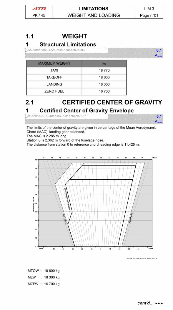
1.1 WEIGHT1 Structural Limitations_2228dfda-fd56-4225-af4a-d3a513b3a203 0.1
ALL
MAXIMUM WEIGHT kg
TAXI 18 770
TAKEOFF 18 600
LANDING 18 300
ZERO FUEL 16 700
2.1 CERTIFIED CENTER OF GRAVITY1 Certified Center of Gravity Envelope_cf6e2dbd-2709-40eb-8637-d1acb4bb7657 5.1
ALLThe limits of the center of gravity are given in percentage of the Mean AerodynamicChord (MAC), landing gear extended.The MAC is 2.285 m long.Station 0 is 2.362 m forward of the fuselage nose.The distance from station 0 to reference chord leading edge is 11.425 m.
ICN-4X-Y-000000-T-FB429-00250-F-01-N
9
10
11
12
13
14
15
16
17
18
19
-50 -40 -30 -20 -10 0 10 20 30 40Index Index
11 13 15 17 19 21 23 25 27 29 31 33 35 %MAC
MTOW : 18 600 kg
MLW : 18 300 kg
MZFW : 16 700 kg
LIMITATIONS LIM 3
PK / 45 WEIGHT AND LOADING Page n°01
cont'd…
WARNINGCERTIFIED CENTER OF GRAVITY ENVELOPE MUST NOT BE USED FOROPERATIONAL PURPOSE. PROPER OPERATIONAL CENTER OF GRAVITYENVELOPE MUST BE DEFINED. REFER TO WBM - WBM LIM.1.16:OPERATIONAL CENTER OF GRAVITY ENVELOPE FOR FURTHER DETAILS.
LIMITATIONS LIM 3
PK / 45 WEIGHT AND LOADING Page n°02
cont'd…

1 AIRSPEED LIMITATIONS_eb3742d5-982f-40e8-9b6f-7982f02ea8e7 2.2
ALL
AIRSPEED IAS
VMO Max. Operating Speed 250 kt
VA Max. Design Maneuvering Speed 160 kt
VFEMax. Flaps ExtendedOperating Speeds
FLAPS 15 180 kt
FLAPS 25 160 kt
FLAPS 35 150 kt
VLE Max. Landing Gear Extended Speed 180 kt
VLO RET Max. Landing Gear Operating Speed(retraction) 160 kt
VLO LOW Max. Landing Gear Operating Speed(extension) 170 kt
VRA Max. Rough Air Speed 180 kt
VWO Max. Wipers Operating Speed 160 kt
CAS
VMCL
FLAPS 15 98.5 kt
FLAPS 25 96 kt
FLAPS 35 96.5 kt
1.1 VMCA Refer to Ops Data
VMCG Refer to AFM/LIMITATIONS/SPEEDS/MINIMUM CONTROL SPEEDS/ TAKEOFFV1 LIMITED BY VMCG
GS
Max. Tyre Speed 165 kt
LIMITATIONS LIM 4
PK / 45 SPEEDS Page n°01

2 Stall Speeds_75a24d19-0792-4722-8597-6daaa678ff42 0.4
ALL
ICN-4X-Y-000000-T-FB429-00011-C-02-N
26 28 30 32 34 36 38
13 14 15 16 17 18 19
35 / DOWN
25 / UP
15 / UP
0 / UP
12
75
95
100
110
WEIGHT (x 1000 lb)
VSR - CAS (kt) FLAPS / GEAR
105
90
85
80
70
115
25 / DOWN
40 42
WEIGHT (x 1000 kg)
3 Recommended Conservative ManeuveringSpeed_f64e59b5-9bc6-4215-b52c-19eb49252432 1.1
ALLWhen performance consideration does not decide use of minimum maneuver speeds,the following conservative maneuvering speeds are recommended.
LIMITATIONS LIM 4
PK / 45 SPEEDS Page n°02
cont'd…
They cover all weight, for high bank operational maneuver, at all flight conditions(normal or icing):
- FLAPS 0: 175 kt- FLAPS 15: 145 kt- FLAPS 25: 135 kt- FLAPS 35: 125 kt
LIMITATIONS LIM 4
PK / 45 SPEEDS Page n°03
cont'd…

PAGE
INTENTIONALLY
LEFT BLANK
LIMITATIONS LIM 4
PK / 45 SPEEDS Page n°04
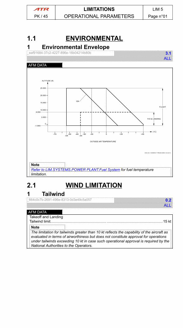
1.1 ENVIRONMENTAL1 Environmental Envelope_eaf91684-37c2-4227-896e-16b04214b80b 3.1
ALLAFM DATA
ICN-XX-Y-000000-T-FB429-00021-D-02-N
-70 -50 -40-54
-20 0 +20 +50
10.000
20.000
25.000
0
-35
(°C)
ALTITUDE (ft)
ISA
FLIGHT
OUTSIDE AIR TEMPERATURE
-30
-1.000
8.500
T/O & LANDING5.000
15.000
NoteRefer to LIM.SYSTEMS.POWER PLANT.Fuel System for fuel temperaturelimitation.
2.1 WIND LIMITATION1 Tailwind_664c0c7b-2691-496e-8313-0d3e49c5a057 0.2
ALLAFM DATATakeoff and LandingTailwind limit................................................ ................................................15 ktNoteThe limitation for tailwinds greater than 10 kt reflects the capability of the aircraft asevaluated in terms of airworthiness but does not constitute approval for operationsunder tailwinds exceeding 10 kt in case such operational approval is required by theNational Authorities to the Operators.
LIMITATIONS LIM 5
PK / 45 OPERATIONAL PARAMETERS Page n°01
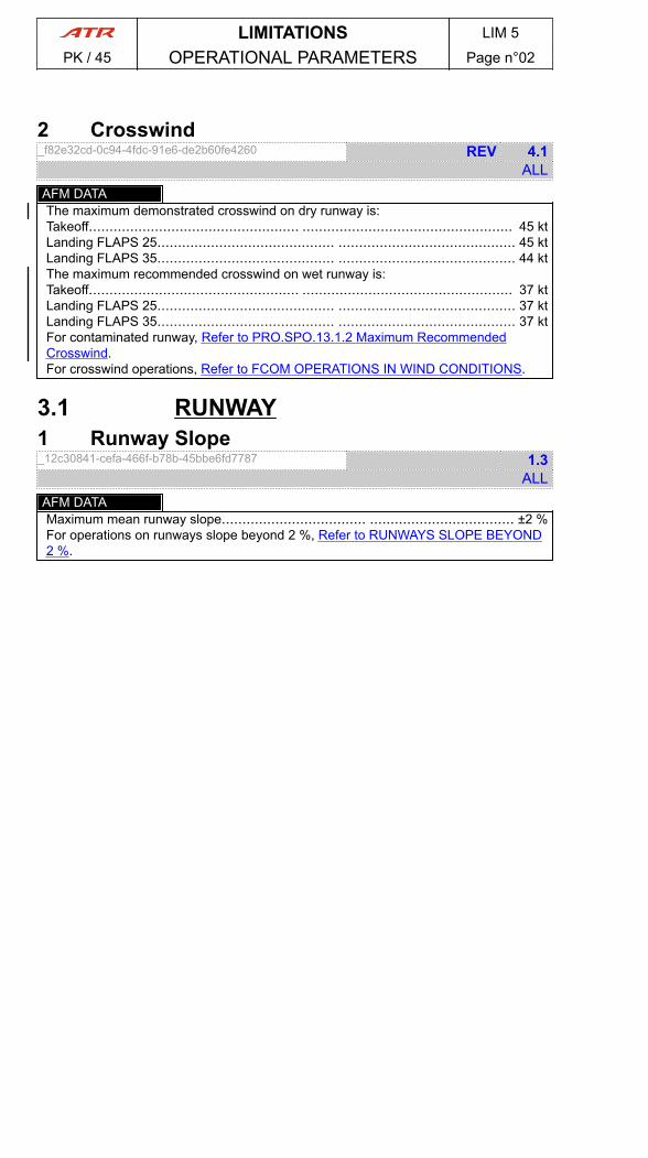
2 Crosswind_f82e32cd-0c94-4fdc-91e6-de2b60fe4260 REV 4.1
ALLAFM DATAThe maximum demonstrated crosswind on dry runway is:Takeoff................................................... ................................................... 45 ktLanding FLAPS 25........................................... ........................................... 45 ktLanding FLAPS 35........................................... ........................................... 44 ktThe maximum recommended crosswind on wet runway is:Takeoff................................................... ................................................... 37 ktLanding FLAPS 25........................................... ........................................... 37 ktLanding FLAPS 35........................................... ........................................... 37 ktFor contaminated runway, Refer to PRO.SPO.13.1.2 Maximum RecommendedCrosswind.For crosswind operations, Refer to FCOM OPERATIONS IN WIND CONDITIONS.
3.1 RUNWAY1 Runway Slope_12c30841-cefa-466f-b78b-45bbe6fd7787 1.3
ALLAFM DATAMaximum mean runway slope................................... ................................... ±2 %For operations on runways slope beyond 2 %, Refer to RUNWAYS SLOPE BEYOND2 %.
LIMITATIONS LIM 5
PK / 45 OPERATIONAL PARAMETERS Page n°02

4.1 DETERMINATION OF WINDCOMPONENT
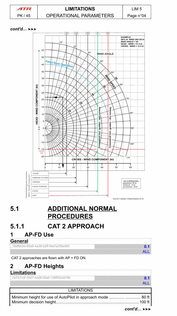
1 CROSSWIND DIAGRAM IN TAKEOFF ANDLANDING_6416d51c-0ce5-41cf-b19c-b60b5ed7f4ec NEW 0.4
ALL1) CROSSWIND DIAGRAM IN TAKE OFF AND LANDING FLAPS 25
1-POOR
3-MEDIUM
5-GOOD
15 22 30 37 45
ICN-XX-Y-000000-T-FB429-00060-A-01-N
110°
100°
90°
80°
70°
60°
50°
40°
30°
20°
10°
0
5
10
15
20
25
30
10
10
10
35
40
45
50
55
-15
-10
-5
-20
100 20 30 40 50 60
EXAMPLE:QFU 25 WIND 280°/25 ktWIND ANGLE = 30°HEAD - WIND = 21.5 ktCROSS - WIND = 12.5 kt
Tailwind limit
WIND ANGLE
CROSS - WIND COMPONENT (kt)
2-MEDIUM TO POOR
4- TO MEDIUMGOOD
6-DRY
Dem
onst
rate
d/R
ecom
men
ded
cros
swin
d lim
it
vs
R
WY
CC
- P
ilot r
epor
t of b
arki
ng a
ctio
n
CAT II OPERATION :Headwind : kt30Tailwind : 1 kt3Crosswind : kt25
Cro
ssw
ind
incl
. gus
tes
- wet
run
way
Cro
ssw
ind
incl
. gus
tes
- dry
run
way
2) CROSSWIND DIAGRAM IN LANDING FLAPS 35
LIMITATIONS LIM 5
PK / 45 OPERATIONAL PARAMETERS Page n°03
cont'd…
1-POOR
3-MEDIUM
5-GOOD
15 22 30 37 44
ICN-XX-Y-000000-T-FB429-00059-A-01-N
110°
100°
90°
80°
70°
60°
50°
40°
30°
20°
10°
0
5
10
15
20
25
30
10
10
10
35
40
45
50
55
-15
-10
-5
-20
100 20 30 40 50 60
EXAMPLE:QFU 25 WIND 280°/25 ktWIND ANGLE = 30°HEAD - WIND = 21.5 ktCROSS - WIND = 12.5 kt
Tailwind limit
WIND ANGLE
CROSS - WIND COMPONENT (kt)
2-MEDIUM TO POOR
4- TO MEDIUMGOOD
6-DRY
Dem
onst
rate
d/R
ecom
men
ded
cros
swin
d lim
it
vs
R
WY
CC
- P
ilot r
epor
t of b
arki
ng a
ctio
n
CAT II OPERATION :Headwind : kt30Tailwind : 1 kt3Crosswind : kt25
Cro
ssw
ind
incl
. gus
tes
- wet
run
way
Cro
ssw
ind
incl
. gus
tes
- dry
run
way
5.1 ADDITIONAL NORMALPROCEDURES
5.1.1 CAT 2 APPROACH1 AP-FD UseGeneral_18df6b3d-85a9-4a38-b2ff-f4a7e258e590 0.1
ALLCAT 2 approaches are flown with AP + FD ON.
2 AP-FD HeightsLimitations_7e7031df-35d7-4dd8-93af-136f052c616b 0.1
ALL
LIMITATIONS
Minimum height for use of AutoPilot in approach mode ............ ............ 80 ftMinimum decision height................................. .................................100 ft
LIMITATIONS LIM 5
PK / 45 OPERATIONAL PARAMETERS Page n°04
cont'd…
cont'd…
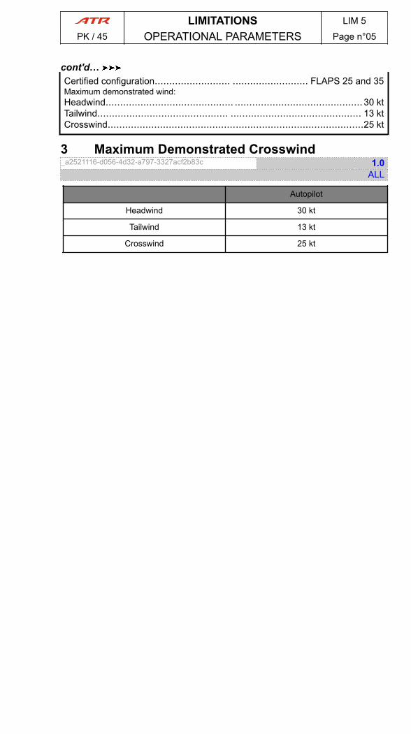
Certified configuration.......................... .......................... FLAPS 25 and 35Maximum demonstrated wind:Headwind............................................ ............................................ 30 ktTailwind............................................. ............................................. 13 ktCrosswind........................................................................................25 kt
3 Maximum Demonstrated Crosswind_a2521116-d056-4d32-a797-3327acf2b83c 1.0
ALL
Autopilot
Headwind 30 kt
Tailwind 13 kt
Crosswind 25 kt
LIMITATIONS LIM 5
PK / 45 OPERATIONAL PARAMETERS Page n°05
cont'd…
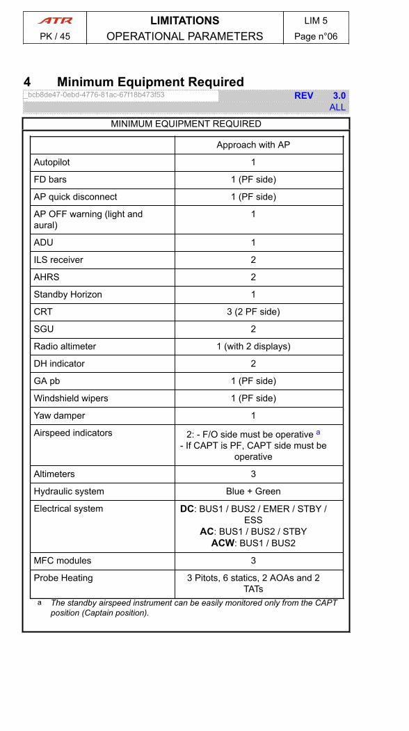
4 Minimum Equipment Required_bcb8de47-0ebd-4776-81ac-67f18b473f53 REV 3.0
ALL
MINIMUM EQUIPMENT REQUIRED
Approach with AP
Autopilot 1
FD bars 1 (PF side)
AP quick disconnect 1 (PF side)
AP OFF warning (light andaural)
1
ADU 1
ILS receiver 2
AHRS 2
Standby Horizon 1
CRT 3 (2 PF side)
SGU 2
Radio altimeter 1 (with 2 displays)
DH indicator 2
GA pb 1 (PF side)
Windshield wipers 1 (PF side)
Yaw damper 1
Airspeed indicators 2: - F/O side must be operative a- If CAPT is PF, CAPT side must be
operative
Altimeters 3
Hydraulic system Blue + Green
Electrical system DC: BUS1 / BUS2 / EMER / STBY /ESS
AC: BUS1 / BUS2 / STBYACW: BUS1 / BUS2
MFC modules 3
Probe Heating 3 Pitots, 6 statics, 2 AOAs and 2TATs
a The standby airspeed instrument can be easily monitored only from the CAPTposition (Captain position).
LIMITATIONS LIM 5
PK / 45 OPERATIONAL PARAMETERS Page n°06

1.1 AIR CONDITIONING1 Pressurization_a7fc672d-de27-491d-8c90-733fdeffaf65 0.1
ALLAFM DATAMaximum differential pressure................................. ................................. 6.35 psiMaximum negative differential pressure........................... ........................... -0.5 psiMaximum differential pressure for landing......................... ......................... 0.35 psiMaximum differential pressure for OVBD VALVE full open selection....................1 psiMaximum altitude for one bleed off operation ...................... ...................... 20 000 ft
2.1 AUTO FLIGHT1 Automatic Flight Control System_c3a644e5-340a-4955-91a4-0bf93333e57a 2.1
ALLNoteFor CAT II operation, Refer to CAT 2 APPROACH.
AFM DATAMinimum height for AP engagement after takeoff............................................ 100 ftNAV mode for VOR approach with either AP or FD is authorized only if:
- A collocated DME is available- DME HOLD is not selected.
Minimum height for use of either AP or FD:- Except during takeoff or approach......................... ......................... 1 000 ft- VS or IAS mode during approach .......................... .......................... 160 ft- CAT I APP mode...................................... ...................................... 160 ft
For CAT II operation, Refer to CAT 2 APPROACH.
3.1 ELECTRICAL POWER1 Electrical System_a9298c1b-49a7-42db-81e2-0eddea1a6b1b 1.0
ALLSingle DC GEN operation :● In flight, if OAT exceeds ISA + 25Flight level must be limited to FL200.
4.1 FLIGHT CONTROLS1 Flaps_45c194a4-4b36-4162-ac33-256aff611625 1.2
ALLAFM DATAHolding with any flaps extended is prohibited in icing conditions (except for singleengine operations).
LIMITATIONS LIM 6
PK / 45 SYSTEMS Page n°01
5.1 ICE AND RAIN PROTECTION1 Ice and Rain Protection_1f431dc4-7cb1-44d2-a881-0c3321d4803d 0.2
ALL
1) Icing ConditionsAFM DATAAll icing detection lights must be operative before a night flight.The ice detector must be operative.
7.1 PBN CAPABILITIES1 PBN Capabilities_cffcd749-6a32-4ac0-a27e-4d2c8b48b584 2.2
ALLPBN capability of Honeywell/Trimble GNSS 1000 operating with HT 1000-60 (or later)software is RNAV5, RNAV2, RNAV1 and RNP1.Minimum Equipment Required:Minimum required equipment to enter RNAV5 airspace is:
- 1 RNAV system, implying:o 1 Current and valid navigation databaseo 1 MCDUo Navigation Source selection (on ECP)o 1 VOR and 1 DME capable of VOR/DME and /or DME/DME position
computation or 1 GNSS receiver- 1 EHSI- 1 EADI.
Minimum required equipment to enter RNAV1/RNAV2 airspace is:- 1 RNAV system, implying:
o 1 Current and valid navigation databaseo 1 MCDUo NAV SOURCE selectiono 1 DME capable of DME/DME position computation or 1 GNSS receiver
(GPS may be required for RNAV1 terminal procedures)- 1 CDI (NAV lateral deviation)- EHSI- EADI.
Minimum required equipment to enter RNP1 airspace is:- 1 RNAV system, implying:
o 1 Current and valid navigation databaseo 1 MCDUo Navigation Source selection (on ECP)o 1 DME capable of DME/DME position computation AND 1 GNSS
receiver- 1 CDI (NAV lateral deviation)- EHSI- EADI.
LIMITATIONS LIM 6
PK / 45 SYSTEMS Page n°02
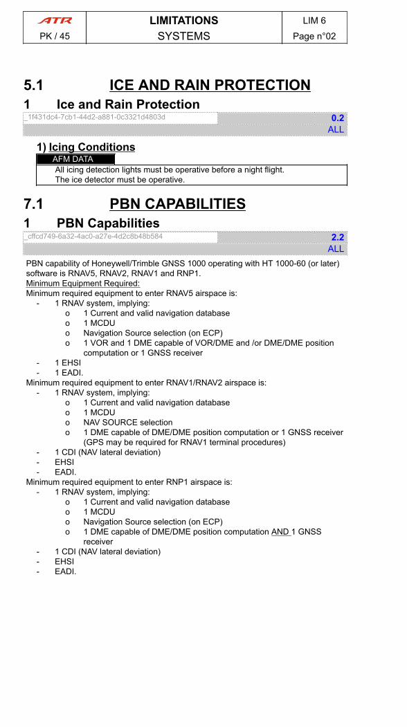
8.1 OXYGEN1 Minimum Bottle Pressure_53d5d86d-1ecd-4f0d-96cb-228f99570e21 REV 1.1
ALL
ICN-4X-Y-350000-T-FB429-00030-A-01-N
0 10 20 30 40 0 50 100 150-10
(minutes)
1900
- Fig. 1 : Available Flight Time after Decompression -
ReferenceTemperature
: Cabin Temperature or OAT, the highest one, on ground
: Cabin Temperature, in flight
Minimum bottle pressure required to cover a cabin depressurization at mid-time of theflight, an emergency descent from 25 000 ft to 13 000 ft within less than 4 min and aflight continuation at an altitude below 13 000 ft.A 25 % pax oxygen consumption is considered.In the case of smoke emission, the system protects the flight crew members during15 min.NoteRefer to national operational regulations to define minimum oxygen quantityrequirement.Minimum oxygen pressure charts :
- Unusable oxygen quantity- Normal system leakage- Reference temperature errors.
9.1 DOORS1 Cargo Door Operation_5c5010fd-2cbe-42d8-8139-ef06ea0c245c 0.1
ALLAFM DATADo not operate cargo door with a lateral wind component of more than 45 kt.
LIMITATIONS LIM 6
PK / 45 SYSTEMS Page n°03
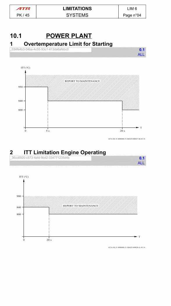
10.1 POWER PLANT1 Overtemperature Limit for Starting_034fe4b3-04ba-4c55-93c1-413da6afebc0 0.1
ALL
ICN-4X-Y-000000-T-FB429-00027-B-01-N
5 s 20 s0
800
840
950
T
ITT (°C)
REPORT TO MAINTENANCE
2 ITT Limitation Engine Operating_36cc6920-c573-4efd-9bd2-334771235d4b 0.1
ALL
ICN-4X-Y-000000-T-FB429-00028-E-01-N
20 s0
840
900
T
ITT (°C)
REPORT TO MAINTENANCE
800
LIMITATIONS LIM 6
PK / 45 SYSTEMS Page n°04
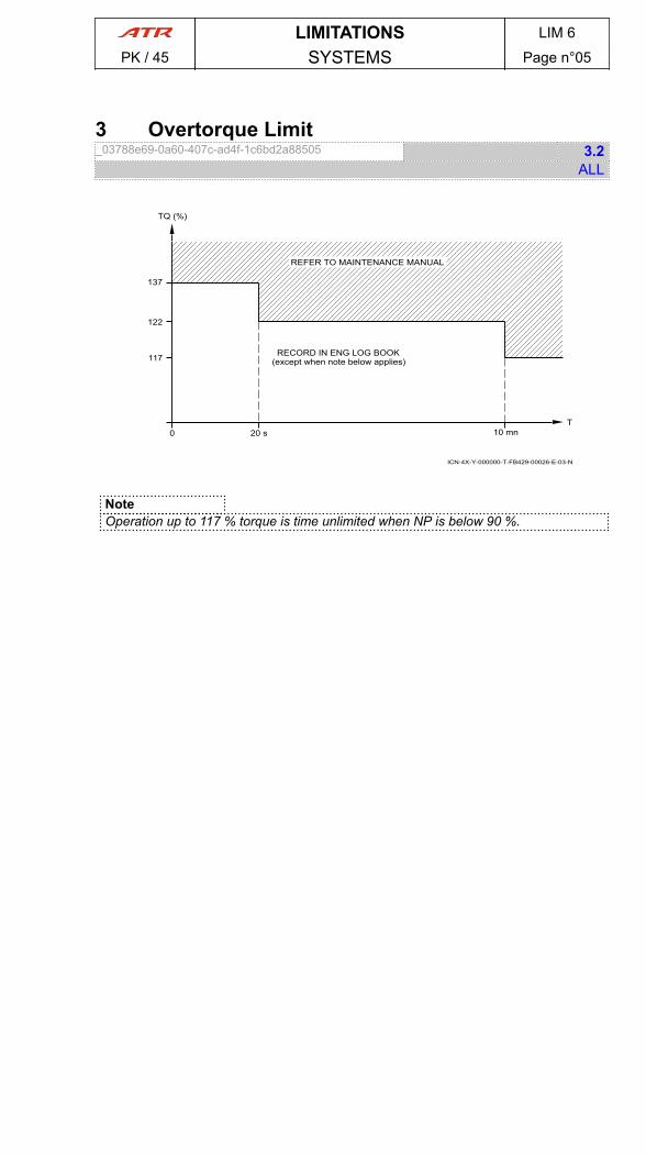
3 Overtorque Limit_03788e69-0a60-407c-ad4f-1c6bd2a88505 3.2
ALL
ICN-4X-Y-000000-T-FB429-00026-E-03-N
20 s 10 mn0
117
122
137
T
TQ (%)
RECORD IN ENG LOG BOOK(except when note below applies)
REFER TO MAINTENANCE MANUAL
NoteOperation up to 117 % torque is time unlimited when NP is below 90 %.
LIMITATIONS LIM 6
PK / 45 SYSTEMS Page n°05
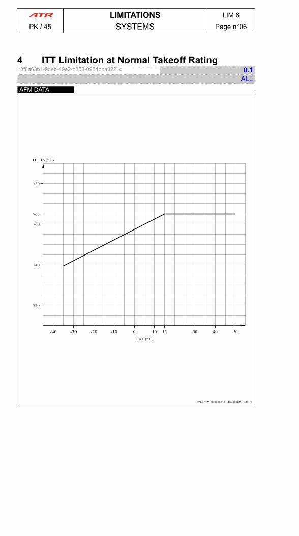
4 ITT Limitation at Normal Takeoff Rating_8f8a63b1-9deb-49e2-b858-0984bba8221d 0.1
ALLAFM DATA
ICN-4X-Y-000000-T-FB429-00025-E-01-N
4010
720
OAT (° C)
-10
ITT T6 (° C)
740
30-40 -30 -20 0 15
760
780
765
50
LIMITATIONS LIM 6
PK / 45 SYSTEMS Page n°06
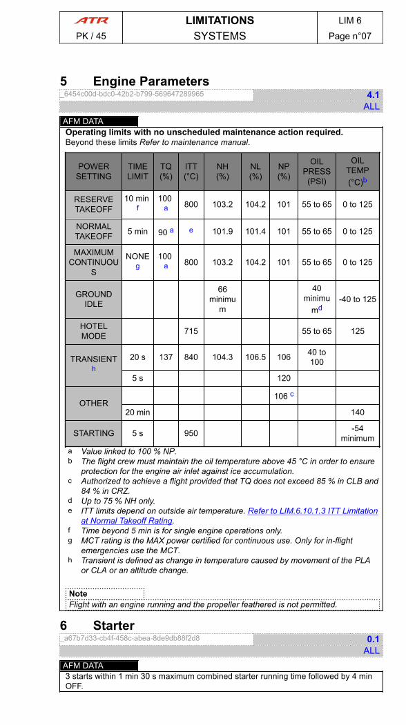
5 Engine Parameters_6454c00d-bdc0-42b2-b799-569647289965 4.1
ALLAFM DATAOperating limits with no unscheduled maintenance action required.Beyond these limits Refer to maintenance manual.
POWERSETTING
TIMELIMIT
TQ(%)
ITT(°C)
NH(%)
NL(%)
NP(%)
OILPRESS(PSI)
OILTEMP(°C)b
RESERVETAKEOFF
10 min f
100 a 800 103.2 104.2 101 55 to 65 0 to 125
NORMALTAKEOFF 5 min 90 a e 101.9 101.4 101 55 to 65 0 to 125
MAXIMUMCONTINUOU
S
NONEg
100 a 800 103.2 104.2 101 55 to 65 0 to 125
GROUNDIDLE
66minimu
m
40minimu
md-40 to 125
HOTELMODE 715 55 to 65 125
TRANSIENTh
20 s 137 840 104.3 106.5 106 40 to100
5 s 120
OTHER106 c
20 min 140
STARTING 5 s 950 -54minimum
a Value linked to 100 % NP.b The flight crew must maintain the oil temperature above 45 °C in order to ensure
protection for the engine air inlet against ice accumulation.c Authorized to achieve a flight provided that TQ does not exceed 85 % in CLB and
84 % in CRZ.d Up to 75 % NH only.e ITT limits depend on outside air temperature. Refer to LIM.6.10.1.3 ITT Limitation
at Normal Takeoff Rating.f Time beyond 5 min is for single engine operations only.g MCT rating is the MAX power certified for continuous use. Only for in-flight
emergencies use the MCT.h Transient is defined as change in temperature caused by movement of the PLA
or CLA or an altitude change.
NoteFlight with an engine running and the propeller feathered is not permitted.
6 Starter_a67b7d33-cb4f-458c-abea-8de9db88f2d8 0.1
ALLAFM DATA3 starts within 1 min 30 s maximum combined starter running time followed by 4 minOFF.
LIMITATIONS LIM 6
PK / 45 SYSTEMS Page n°07
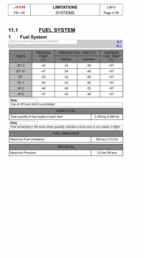
11.1 FUEL SYSTEM1 Fuel System_b7eba2e2-f0fd-4230-be2a-5e7ab8bd3d18 0.1
ALL
FUELSFREEZING
POINT(°C)
MINIMUM FUEL TEMP (°C) MAXIMUMFUEL TEMP
(°C)Starting Operation
JET A -40 -34 -38 +57
JET A1 -47 -34 -48 +57
RT -55 -34 -60 +57
TS–1 -60 -34 -60 +57
JP 5 -46 -26 -33 +57
JP 8 -47 -34 -48 +57
NoteUse of JP4 and Jet B is prohibited.
USABLE FUEL
Total quantity of fuel usable in each tank 2 250 kg (4 960 lb)
NoteFuel remaining in the tanks when quantity indicators show zero is not usable in flight.
FUEL UNBALANCE
Maximum Fuel Unbalance 550 kg (1 212 lb)
REFUELING
Maximum Pressure 3.5 bar (50 psi)
LIMITATIONS LIM 6
PK / 45 SYSTEMS Page n°08
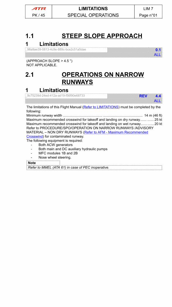
1.1 STEEP SLOPE APPROACH1 Limitations_98a9ae39-0813-4c9e-889c-bce2c51a5dae 0.1
ALL(APPROACH SLOPE > 4.5 °)NOT APPLICABLE.
2.1 OPERATIONS ON NARROWRUNWAYS
1 Limitations_9c75239d-24ed-412a-ad19-f56f90e68733 REV 4.4
ALLThe limitations of this Flight Manual (Refer to LIMITATIONS) must be completed by thefollowing:Minimum runway width .................................... .................................... 14 m (46 ft)Maximum recommended crosswind for takeoff and landing on dry runway...... ...... 25 ktMaximum recommended crosswind for takeoff and landing on wet runway...... ......20 ktRefer to PROCEDURE/SPO/OPERATION ON NARROW RUNWAYS /ADVISORYMATERIAL – NON DRY RUNWAYS (Refer to AFM - Maximum RecommendedCrosswind) for contaminated runway.The following equipment is required:
- Both ACW generators- Both main and DC auxiliary hydraulic pumps- MFC modules 1B and 2B- Nose wheel steering.
NoteRefer to MMEL (ATA 61) in case of PEC inoperative.
LIMITATIONS LIM 7
PK / 45 SPECIAL OPERATIONS Page n°01

PAGE
INTENTIONALLY
LEFT BLANK
LIMITATIONS LIM 7
PK / 45 SPECIAL OPERATIONS Page n°02

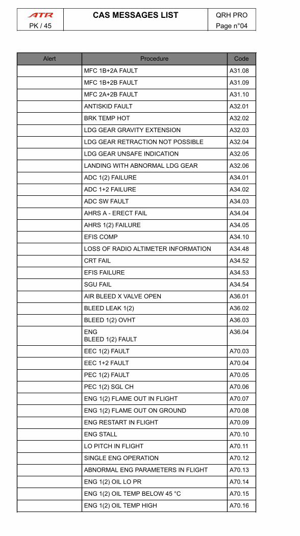
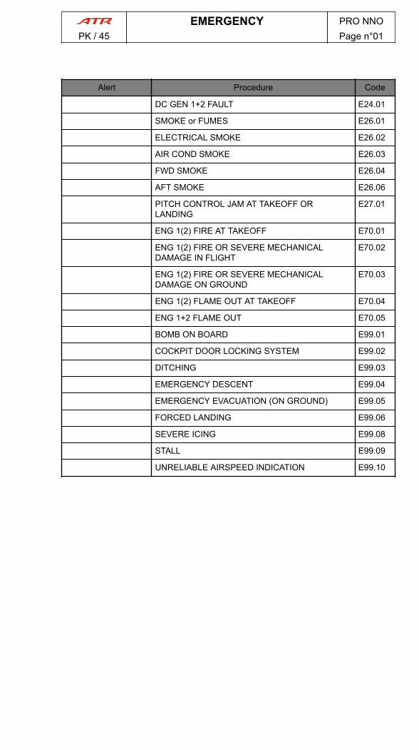
Alert Procedure Code
DC GEN 1+2 FAULT E24.01
SMOKE or FUMES E26.01
ELECTRICAL SMOKE E26.02
AIR COND SMOKE E26.03
FWD SMOKE E26.04
AFT SMOKE E26.06
PITCH CONTROL JAM AT TAKEOFF ORLANDING
E27.01
ENG 1(2) FIRE AT TAKEOFF E70.01
ENG 1(2) FIRE OR SEVERE MECHANICALDAMAGE IN FLIGHT
E70.02
ENG 1(2) FIRE OR SEVERE MECHANICALDAMAGE ON GROUND
E70.03
ENG 1(2) FLAME OUT AT TAKEOFF E70.04
ENG 1+2 FLAME OUT E70.05
BOMB ON BOARD E99.01
COCKPIT DOOR LOCKING SYSTEM E99.02
DITCHING E99.03
EMERGENCY DESCENT E99.04
EMERGENCY EVACUATION (ON GROUND) E99.05
FORCED LANDING E99.06
SEVERE ICING E99.08
STALL E99.09
UNRELIABLE AIRSPEED INDICATION E99.10
DUCT 1(2) OVHT A21.01
PACK 1(2) VALVE FAULT A21.02
PACK 1+2 VALVES FAULT A21.03
RECIRC FAN 1(2) FAULT A21.06
AVIONICS VENT EXHAUST MODE FAULT A21.08
OVBD VALVE FAULT A21.09
AUTO PRESS FAULT A21.10
EXCESS CAB ALT A21.13
EXCESS CAB DELTA P A21.14
ABNORMAL FLIGHT CHARACTERISTICS INROLL
A22.01
ADU FAILURE A22.02
AILERON MISTRIM (ADU MESSAGE) A22.03
AP PITCH TRIM FAIL (ADU MESSAGE) A22.04
DADC DATA INVALID (ADU MESSAGE) A22.05
CAS MESSAGES LIST QRH PROPK / 45 Page n°01
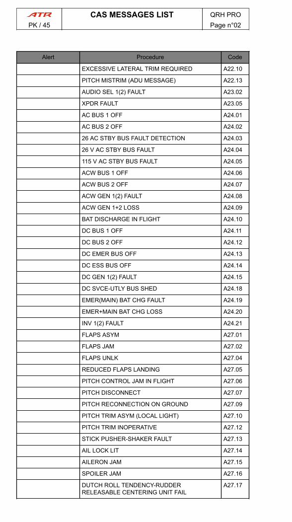
Alert Procedure Code
EXCESSIVE LATERAL TRIM REQUIRED A22.10
PITCH MISTRIM (ADU MESSAGE) A22.13
AUDIO SEL 1(2) FAULT A23.02
XPDR FAULT A23.05
AC BUS 1 OFF A24.01
AC BUS 2 OFF A24.02
26 AC STBY BUS FAULT DETECTION A24.03
26 V AC STBY BUS FAULT A24.04
115 V AC STBY BUS FAULT A24.05
ACW BUS 1 OFF A24.06
ACW BUS 2 OFF A24.07
ACW GEN 1(2) FAULT A24.08
ACW GEN 1+2 LOSS A24.09
BAT DISCHARGE IN FLIGHT A24.10
DC BUS 1 OFF A24.11
DC BUS 2 OFF A24.12
DC EMER BUS OFF A24.13
DC ESS BUS OFF A24.14
DC GEN 1(2) FAULT A24.15
DC SVCE-UTLY BUS SHED A24.18
EMER(MAIN) BAT CHG FAULT A24.19
EMER+MAIN BAT CHG LOSS A24.20
INV 1(2) FAULT A24.21
FLAPS ASYM A27.01
FLAPS JAM A27.02
FLAPS UNLK A27.04
REDUCED FLAPS LANDING A27.05
PITCH CONTROL JAM IN FLIGHT A27.06
PITCH DISCONNECT A27.07
PITCH RECONNECTION ON GROUND A27.09
PITCH TRIM ASYM (LOCAL LIGHT) A27.10
PITCH TRIM INOPERATIVE A27.12
STICK PUSHER-SHAKER FAULT A27.13
AIL LOCK LIT A27.14
AILERON JAM A27.15
SPOILER JAM A27.16
DUTCH ROLL TENDENCY-RUDDERRELEASABLE CENTERING UNIT FAIL
A27.17
CAS MESSAGES LIST QRH PROPK / 45 Page n°02
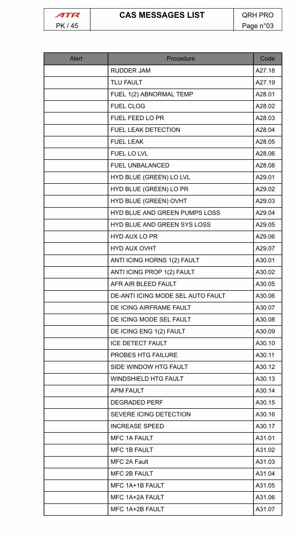
Alert Procedure Code
RUDDER JAM A27.18
TLU FAULT A27.19
FUEL 1(2) ABNORMAL TEMP A28.01
FUEL CLOG A28.02
FUEL FEED LO PR A28.03
FUEL LEAK DETECTION A28.04
FUEL LEAK A28.05
FUEL LO LVL A28.06
FUEL UNBALANCED A28.08
HYD BLUE (GREEN) LO LVL A29.01
HYD BLUE (GREEN) LO PR A29.02
HYD BLUE (GREEN) OVHT A29.03
HYD BLUE AND GREEN PUMPS LOSS A29.04
HYD BLUE AND GREEN SYS LOSS A29.05
HYD AUX LO PR A29.06
HYD AUX OVHT A29.07
ANTI ICING HORNS 1(2) FAULT A30.01
ANTI ICING PROP 1(2) FAULT A30.02
AFR AIR BLEED FAULT A30.05
DE-ANTI ICING MODE SEL AUTO FAULT A30.06
DE ICING AIRFRAME FAULT A30.07
DE ICING MODE SEL FAULT A30.08
DE ICING ENG 1(2) FAULT A30.09
ICE DETECT FAULT A30.10
PROBES HTG FAILURE A30.11
SIDE WINDOW HTG FAULT A30.12
WINDSHIELD HTG FAULT A30.13
APM FAULT A30.14
DEGRADED PERF A30.15
SEVERE ICING DETECTION A30.16
INCREASE SPEED A30.17
MFC 1A FAULT A31.01
MFC 1B FAULT A31.02
MFC 2A Fault A31.03
MFC 2B FAULT A31.04
MFC 1A+1B FAULT A31.05
MFC 1A+2A FAULT A31.06
MFC 1A+2B FAULT A31.07
CAS MESSAGES LIST QRH PROPK / 45 Page n°03
Alert Procedure Code
MFC 1B+2A FAULT A31.08
MFC 1B+2B FAULT A31.09
MFC 2A+2B FAULT A31.10
ANTISKID FAULT A32.01
BRK TEMP HOT A32.02
LDG GEAR GRAVITY EXTENSION A32.03
LDG GEAR RETRACTION NOT POSSIBLE A32.04
LDG GEAR UNSAFE INDICATION A32.05
LANDING WITH ABNORMAL LDG GEAR A32.06
ADC 1(2) FAILURE A34.01
ADC 1+2 FAILURE A34.02
ADC SW FAULT A34.03
AHRS A - ERECT FAIL A34.04
AHRS 1(2) FAILURE A34.05
EFIS COMP A34.10
LOSS OF RADIO ALTIMETER INFORMATION A34.48
CRT FAIL A34.52
EFIS FAILURE A34.53
SGU FAIL A34.54
AIR BLEED X VALVE OPEN A36.01
BLEED LEAK 1(2) A36.02
BLEED 1(2) OVHT A36.03
ENGBLEED 1(2) FAULT
A36.04
EEC 1(2) FAULT A70.03
EEC 1+2 FAULT A70.04
PEC 1(2) FAULT A70.05
PEC 1(2) SGL CH A70.06
ENG 1(2) FLAME OUT IN FLIGHT A70.07
ENG 1(2) FLAME OUT ON GROUND A70.08
ENG RESTART IN FLIGHT A70.09
ENG STALL A70.10
LO PITCH IN FLIGHT A70.11
SINGLE ENG OPERATION A70.12
ABNORMAL ENG PARAMETERS IN FLIGHT A70.13
ENG 1(2) OIL LO PR A70.14
ENG 1(2) OIL TEMP BELOW 45 °C A70.15
ENG 1(2) OIL TEMP HIGH A70.16
CAS MESSAGES LIST QRH PROPK / 45 Page n°04
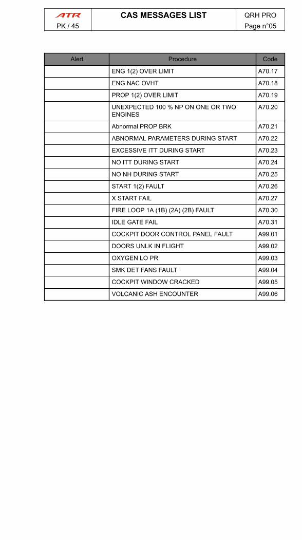
Alert Procedure Code
ENG 1(2) OVER LIMIT A70.17
ENG NAC OVHT A70.18
PROP 1(2) OVER LIMIT A70.19
UNEXPECTED 100 % NP ON ONE OR TWOENGINES
A70.20
Abnormal PROP BRK A70.21
ABNORMAL PARAMETERS DURING START A70.22
EXCESSIVE ITT DURING START A70.23
NO ITT DURING START A70.24
NO NH DURING START A70.25
START 1(2) FAULT A70.26
X START FAIL A70.27
FIRE LOOP 1A (1B) (2A) (2B) FAULT A70.30
IDLE GATE FAIL A70.31
COCKPIT DOOR CONTROL PANEL FAULT A99.01
DOORS UNLK IN FLIGHT A99.02
OXYGEN LO PR A99.03
SMK DET FANS FAULT A99.04
COCKPIT WINDOW CRACKED A99.05
VOLCANIC ASH ENCOUNTER A99.06
CAS MESSAGES LIST QRH PROPK / 45 Page n°05

PAGE
INTENTIONALLY
LEFT BLANK
CAS MESSAGES LIST QRH PROPK / 45 Page n°06

1 General_bc2abd95-11dc-4339-9e3d-18450d46b5c9 1.4
ALL1) Memory Item
- Memory item are BOXED.- Boxed actions are considered time-critical and should be memorized and
executed from memory.2) Actions
- Actions are identified by the symbol ►.- Actions can be immediate in the form of ►CHALLENGE………RESPONSE, or
lasting in the form of ► SYSTEM STATE or ACTION or VALUE :DESCRIPTION.
- A lasting action can be for the remaining of flight, phase, or as long as acondition exist.
3) Conditions- When an action(s) is dependent of a condition the condition is identified by the
symbol ■.4) Phases
- When actions have to be applied at phase of procedure/flight is identified by thesymbol ●.
5) Information- Applicable information associated with an action of failure situation is presented
in all capital letters without any symbol e.g. MAINTENANCE ACTIONREQUIRED, AP CAN BE REENGAGED.
6) Procedures – Checklists PrioritiesProcedures in QRH are classified in 3 parts:
- EMERGENCY- NORMAL- ABNORMAL
The CCAS generates alerts (Warnings & Cautions) as soon as a system malfunction isdetected.The flight crew has to comply with the same hierarchy (Emergency, normal andabnormal procedures) when using QRH.7) Flight phases sections versus Normal ChecklistsSome emergency or abnormal procedures contains flight phase sections that are not asubstitude for the normal checklist.For example, "Before landing" section in the ACW GEN 1+2 LOSS procedure or inother emergency or abnormal procedures must be applied when required, and "BeforeLanding" normal checklist remains mandatory and applicable as per checklistmethodology.
PROCEDURE PRO PLEPK / 45 Page n°01

PAGE
INTENTIONALLY
LEFT BLANK
PROCEDURE PRO PLEPK / 45 Page n°02
Alert Procedure Code
DC GEN 1+2 FAULT E24.01
SMOKE or FUMES E26.01
ELECTRICAL SMOKE E26.02
AIR COND SMOKE E26.03
FWD SMOKE E26.04
AFT SMOKE E26.06
PITCH CONTROL JAM AT TAKEOFF ORLANDING
E27.01
ENG 1(2) FIRE AT TAKEOFF E70.01
ENG 1(2) FIRE OR SEVERE MECHANICALDAMAGE IN FLIGHT
E70.02
ENG 1(2) FIRE OR SEVERE MECHANICALDAMAGE ON GROUND
E70.03
ENG 1(2) FLAME OUT AT TAKEOFF E70.04
ENG 1+2 FLAME OUT E70.05
BOMB ON BOARD E99.01
COCKPIT DOOR LOCKING SYSTEM E99.02
DITCHING E99.03
EMERGENCY DESCENT E99.04
EMERGENCY EVACUATION (ON GROUND) E99.05
FORCED LANDING E99.06
SEVERE ICING E99.08
STALL E99.09
UNRELIABLE AIRSPEED INDICATION E99.10
EMERGENCY PRO NNOPK / 45 Page n°01

PAGE
INTENTIONALLY
LEFT BLANK
EMERGENCY PRO NNOPK / 45 Page n°02
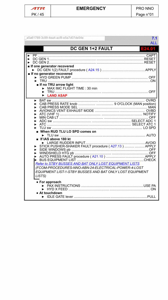
_a5a61789-3c99-4ea4-acf8-e5a7d07de54e 7.1ALL
- E24.01DC GEN 1+2 FAULT▶ PF .................................................................................................... CAPT▶ DC GEN 1............................................ ............................................ RESET▶ DC GEN 2............................................ ............................................ RESET■ If one generator recovered▶ DC GEN 1(2) FAULT procedure ( A24.15 ) ........................................APPLY
■ If no generator recovered▶ HYD GREEN PUMP ................................... ................................... OFF▶ TRU ................................................................................................ON
■ If no TRU arrow light▶ MAX IMC FLIGHT TIME : 30 min▶ TRU ........................................... ........................................... OFF▶ LAND ASAP
▶ BAT sw ........................................... ........................................... OVRD▶ CAB PRESS RATE knob ................ ................ 9 O'CLOCK (MAN position)▶ CAB PRESS MODE SEL ................................................................ MAN▶ AVIONICS VENT EXHAUST MODE ....................... ....................... OVBD▶ ATC (VHF 1) ...................................... ...................................... NOTIFY▶ MIN CAB LT ......................................... ......................................... OFF▶ ADC sw .................................... .................................... SELECT ADC 1▶ ATC ....................................... ....................................... SELECT ATC 1▶ TLU sw .................................................................................... LO SPD
■ When RUD TLU LO SPD comes on▶ TLU sw ................................................................................ AUTO
■ If IAS above 180 kt▶ LARGE RUDDER INPUT........................................................AVOID
▶ STICK PUSHER-SHAKER FAULT procedure ( A27.13 ) ......... ......... APPLY▶ SIDE WINDOWS pb ........................................................................OFF▶ WINDSHIELD HTG pb .................................. .................................. OFF▶ AUTO PRESS FAULT procedure ( A21.10 ) ....................................APPLY▶ BUS EQUIPMENT LIST ............................... ...............................CHECKRefer to STBY BUSSES AND BAT ONLY LOST EQUIPMENT LISTS(FCOM-PROCEDURES-NNO-ABN-24-ELECTRICAL-POWER-4-LOSTEQUIPMENT LIST-1-STBY BUSSES AND BAT ONLY LOST EQUIPMENTLISTS)
● For approach▶ PAX INSTRUCTIONS ..........................................................USE PA▶ HYD X FEED ...................................... ......................................ON
● At touchdown▶ IDLE GATE lever ....................................................................PULL
EMERGENCY PRO NNOPK / 45 Page n°01

PAGE
INTENTIONALLY
LEFT BLANK
EMERGENCY PRO NNOPK / 45 Page n°02

EMR.26 SMOKE
_7d2c74a9-e6e1-4855-8fb5-15c18e9b8b95 6.2ALL
- E26.01SMOKE OR FUMES
■ If smoke/fumes in the cockpit▶ CREW OXY MASKS........... ........... DON / 100 %▶GOGGLES................................................DON▶ CREW COMMUNICATIONS...... ...... ESTABLISH
▶ RECIRC FANS 1+2................... ................... OFF▶ AP ............................... ............................... ON▶ CABIN CREW COMMUNICATIONS.. .. ESTABLISH
CAUTIONELEC SMK warning may be triggered by an air conditioningsmoke source.
▶ SMOKE / FUMES SOURCE ................IDENTIFY■ If electrical smoke/fumes identified▶ ELECTRICAL SMOKE procedure ( E26.02 ) ........
............................................................. APPLY■ If air conditioning smoke/fumes identified▶ AIR COND SMOKE procedure ( E26.03 ) ............
............................................................. APPLY■ If FWD SMK comes on or smoke/fumes in FWDzone of aircraft▶ FWD SMOKE procedure ( E26.04 ) ..... .....APPLY
■ If AFT SMK comes on or smoke/fumes in aft zoneof aircraft▶ AFT SMOKE procedure ( E26.06 ) ............APPLY
■ If smoke/fumes source not identifiedNoteRefer to FCOM - QRH PRO/NNO/EMR/26/SMOKE SOURCEDETECTION provides additional guidance to identify smoke/fumes source.
▶ ELECTRICAL SMOKE procedure ( E26.02 ) ..................................................................... APPLY
EMERGENCY PRO NNOPK / 45 Page n°01
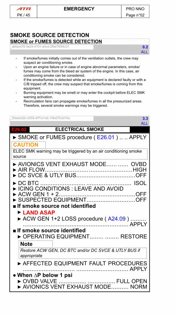
SMOKE SOURCE DETECTIONSMOKE or FUMES SOURCE DETECTION_abfacd78-3e24-4101-a4cd-2fbe750f4c31 0.2
ALL- If smoke/fumes initially comes out of the ventilation outlets, the crew may
suspect air conditioning smoke.- Upon an engine failure or in case of engine abnormal parameters, smoke/
fumes may come from the bleed air system of the engine. In this case, airconditioning smoke can be considered.
- If the smoke/fumes is detected while an equipment is declared faulty or with aC/B tripped off, the crew may suspect that smoke/fumes is coming from thisequipment.
- Burning equipment may be smelt or may enter the cockpit before ELEC SMKwarning activation.
- Recirculation fans can propagate smoke/fumes in all the pressurized areas.Therefore, several smoke warnings may be triggered.
_50eded2b-d359-4f7f-b1eb-1f4e07b3d10e 3.3ALL
- E26.02 ELECTRICAL SMOKE▶ SMOKE or FUMES procedure ( E26.01 ) .. .. APPLYCAUTIONELEC SMK warning may be triggered by an air conditioning smokesource
▶ AVIONICS VENT EXHAUST MODE...... ...... OVBD▶ AIR FLOW......................... .........................HIGH▶ DC SVCE & UTLY BUS..................................OFF▶ DC BTC .......................... .......................... ISOL▶ ICING CONDITIONS : LEAVE AND AVOID▶ ACW GEN 1 + 2............................................OFF▶ SUSPECTED EQUIPMENT............................OFF■ If smoke source not identified▶ LAND ASAP▶ ACW GEN 1+2 LOSS procedure ( A24.09 ) .........
............................................................. APPLY■ If smoke source identified▶OPERATING EQUIPMENT........ ........ RESTORENoteRestore ACW GEN, DC BTC and/or DC SVCE & UTLY BUS ifappropriate
▶ AFFECTED EQUIPMENT FAULT PROCEDURES.............................. .............................. APPLY
● When ∆P below 1 psi▶OVBD VALVE ................ ................ FULL OPEN▶ AVIONICS VENT EXHAUST MODE.......... NORM
EMERGENCY PRO NNOPK / 45 Page n°02
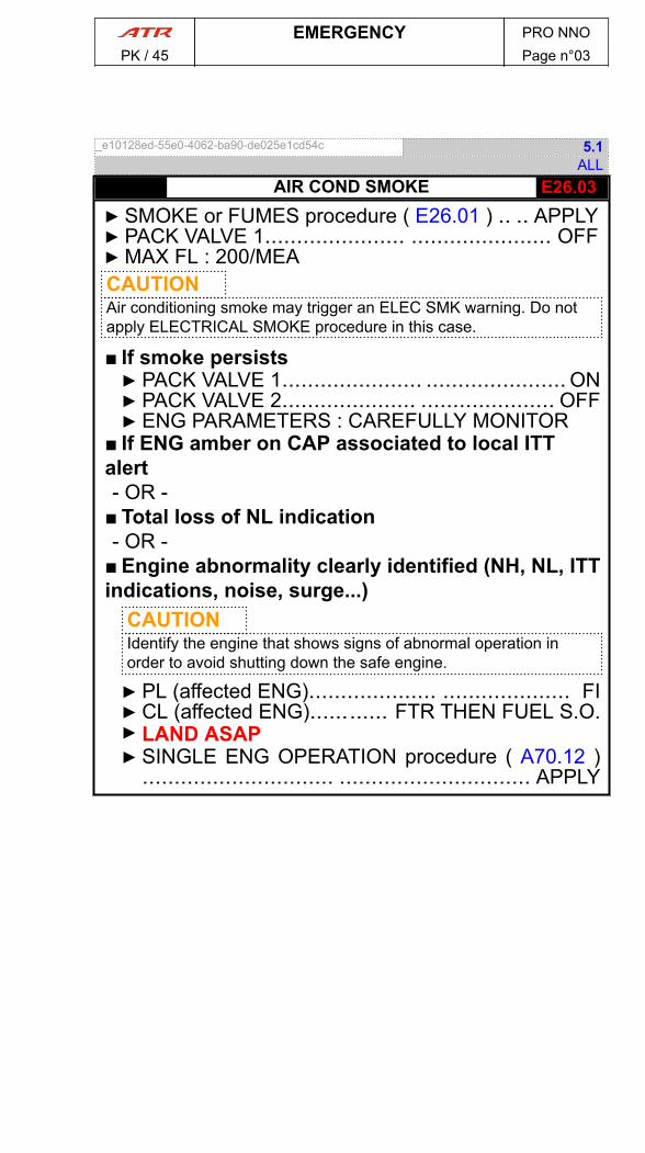
_e10128ed-55e0-4062-ba90-de025e1cd54c 5.1ALL
- E26.03AIR COND SMOKE▶ SMOKE or FUMES procedure ( E26.01 ) .. .. APPLY▶ PACK VALVE 1...................... ...................... OFF▶MAX FL : 200/MEACAUTIONAir conditioning smoke may trigger an ELEC SMK warning. Do notapply ELECTRICAL SMOKE procedure in this case.
■ If smoke persists▶ PACK VALVE 1...................... ...................... ON▶ PACK VALVE 2..................... ..................... OFF▶ ENG PARAMETERS : CAREFULLY MONITOR
■ If ENG amber on CAP associated to local ITTalert- OR -
■ Total loss of NL indication- OR -
■ Engine abnormality clearly identified (NH, NL, ITTindications, noise, surge...)
CAUTIONIdentify the engine that shows signs of abnormal operation inorder to avoid shutting down the safe engine.
▶ PL (affected ENG).................... .................... FI▶ CL (affected ENG)............ FTR THEN FUEL S.O.▶ LAND ASAP▶ SINGLE ENG OPERATION procedure ( A70.12 )
.............................. .............................. APPLY
EMERGENCY PRO NNOPK / 45 Page n°03
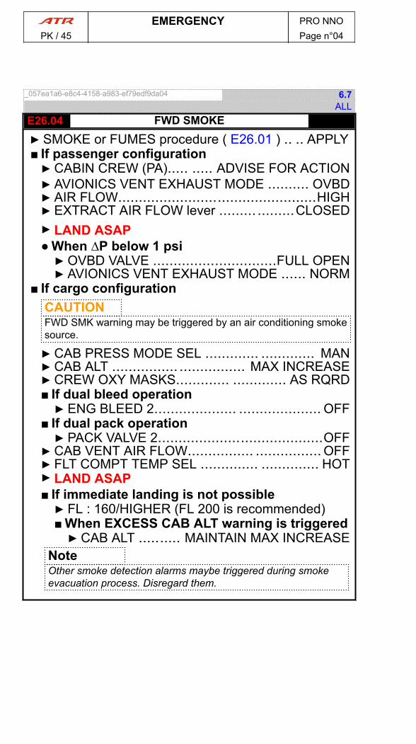
_057ea1a6-e8c4-4158-a983-ef79edf9da04 6.7ALL
- E26.04 FWD SMOKE▶ SMOKE or FUMES procedure ( E26.01 ) .. .. APPLY■ If passenger configuration▶ CABIN CREW (PA)..... ..... ADVISE FOR ACTION▶ AVIONICS VENT EXHAUST MODE .......... OVBD▶ AIR FLOW................................................HIGH▶ EXTRACT AIR FLOW lever ......... .........CLOSED▶ LAND ASAP● When ∆P below 1 psi▶OVBD VALVE ..............................FULL OPEN▶ AVIONICS VENT EXHAUST MODE ...... NORM
■ If cargo configurationCAUTIONFWD SMK warning may be triggered by an air conditioning smokesource.
▶ CAB PRESS MODE SEL ............. ............. MAN▶ CAB ALT ................ ................ MAX INCREASE▶ CREW OXY MASKS............. ............. AS RQRD■ If dual bleed operation▶ ENG BLEED 2.................... .................... OFF
■ If dual pack operation▶ PACK VALVE 2........................................OFF
▶ CAB VENT AIR FLOW................ ................ OFF▶ FLT COMPT TEMP SEL .............. .............. HOT▶ LAND ASAP■ If immediate landing is not possible▶ FL : 160/HIGHER (FL 200 is recommended)■ When EXCESS CAB ALT warning is triggered▶ CAB ALT .......... MAINTAIN MAX INCREASE
NoteOther smoke detection alarms maybe triggered during smokeevacuation process. Disregard them.
EMERGENCY PRO NNOPK / 45 Page n°04
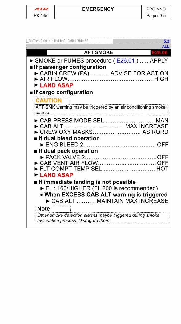
_0af7a442-901d-41b5-bbfa-0c5b1f3bb452 5.3ALL
- E26.06AFT SMOKE▶ SMOKE or FUMES procedure ( E26.01 ) .. .. APPLY■ If passenger configuration▶ CABIN CREW (PA)..... ..... ADVISE FOR ACTION▶ AIR FLOW................................................HIGH▶ LAND ASAP
■ If cargo configurationCAUTIONAFT SMK warning may be triggered by an air conditioning smokesource.
▶ CAB PRESS MODE SEL ............. ............. MAN▶ CAB ALT ................ ................ MAX INCREASE▶ CREW OXY MASKS............. ............. AS RQRD■ If dual bleed operation▶ ENG BLEED 2.................... .................... OFF
■ If dual pack operation▶ PACK VALVE 2........................................OFF
▶ CAB VENT AIR FLOW................ ................ OFF▶ FLT COMPT TEMP SEL .............. .............. HOT▶ LAND ASAP■ If immediate landing is not possible▶ FL : 160/HIGHER (FL 200 is recommended)● When EXCESS CAB ALT warning is triggered▶ CAB ALT .......... MAINTAIN MAX INCREASE
NoteOther smoke detection alarms maybe triggered during smokeevacuation process. Disregard them.
EMERGENCY PRO NNOPK / 45 Page n°05

PAGE
INTENTIONALLY
LEFT BLANK
EMERGENCY PRO NNOPK / 45 Page n°06

EMR.27 FLIGHT CONTROLS
_e2d6a6fe-cd3a-4bd2-a65d-c2f93ffd7cfc 2.1ALL
- E27.01PITCH CONTROL JAM AT TAKEOFF ORLANDING
▶ MAX IAS : 180 kt▶ CONTROL COLUMNS................................................................UNCOUPLE▶ FREE CONTROL COLUMN............................................................IDENTIFY▶ PF..............................................................FREE CONTROL COLUMN SIDE▶ PITCH DISCONNECT procedure ( A27.07 ) ..........................................APPLY
EMERGENCY PRO NNOPK / 45 Page n°01

PAGE
INTENTIONALLY
LEFT BLANK
EMERGENCY PRO NNOPK / 45 Page n°02

_a59ac6be-ceda-4256-adc0-efba27c1cca1 4.5ALL
- E70.01ENG 1(2) FIRE AT TAKEOFFNoteCaptain may decide to shut down affected engine before reaching accelerationaltitude, but not before 400 ft AGL
● WHEN AIRBORNE▶ LDG GEAR..........................................................................................UP
● AT ACCELERATION ALTITUDE▶ PWR MGT ........................................... ........................................... MCT
● AT VFTO■ If normal conditions▶ FLAPS..............................................................................................0
■ If icing conditions▶ FLAPS : MAINTAIN 15°
▶ PL (affected ENG)........................................ ........................................ FI▶ CL (affected ENG)......................... ......................... FTR THEN FUEL S.O.▶ FIRE HANDLE (affected ENG)............................. ............................. PULL■ If fire persists after 10 s▶ AGENT 1 (affected ENG)............................................................DISCH■ If fire persists 30 s after AGENT 1 DISCH▶ AGENT 2 (affected ENG)........................... ........................... DISCH
▶ LAND ASAP▶ BLEED (operating ENG)......................................................OFF (if necessary)▶ ATC................................................ ................................................ NOTIFY▶ ENG (affected) : DO NOT RESTART▶ SINGLE ENG OPERATION procedure ( A70.12 ) ................. ................. APPLY
_a82963e0-df9b-43e1-a3fe-b607b9a30dc1 2.4ALL
- E70.02ENG 1(2) FIRE OR SEVERE MECHANICALDAMAGE IN FLIGHT
▶ PL (affected ENG).......................................... .......................................... FI▶ CL (affected ENG)........................... ........................... FTR THEN FUEL S.O.▶ FIRE HANDLE (affected ENG)............................... ............................... PULL■ If fire persists after 10 s▶ AGENT 1 (affected ENG)................................ ................................ DISCH■ If fire persists 30 s after AGENT 1 DISCH▶ AGENT 2 (affected ENG)............................................................DISCH
▶ LAND ASAP▶ ATC................................................ ................................................ NOTIFY▶ ENG (affected) : DO NOT RESTART▶ SINGLE ENG OPERATION procedure ( A70.12 ) ................. ................. APPLY
EMERGENCY PRO NNOPK / 45 Page n°01

_57751aa9-ee1c-400c-9bf1-83f854c2e5e2 3.4ALL
- E70.03 ENG 1(2) FIRE OR SEVERE MECHANICALDAMAGE ON GROUND
▶ AIRCRAFT..........................................................................................STOP▶ BRAKE HANDLE............................................................................PARKING▶ CL 1+2................................... ................................... FTR THEN FUEL S.O.▶ FIRE HANDLE (affected ENG)............................... ............................... PULL■ If fire persists▶ AGENT 1 (affected ENG)................................ ................................ DISCH■ If fire persists 30 s after AGENT 1 DISCH▶ AGENT 2 (affected ENG)............................................................DISCH
▶ ATC (VHF 1).......................................... .......................................... NOTIFY■ If evacuation required▶ EMERGENCY EVACUATION (ON GROUND) procedure ( E99.05 ) ... ..APPLY
_68595bbb-7052-4b4b-bbb4-d217d85b9328 2.1ALL
- E70.04 ENG 1(2) FLAME OUT AT TAKEOFF▶ AUTOFEATHER................................................................................CHECK▶ UPTRIM............................................. ............................................. CHECK■ If no UPTRIM▶ PL 1 + 2.............................. .............................. ADVANCE TO THE RAMP
● WHEN AIRBORNE▶ LDG GEAR..........................................................................................UP■ If NO BLEEDS 1 + 2 FAULT▶ BLEEDS 1 + 2....................................... ....................................... OFF
● AT ACCELERATION ALTITUDE▶ ALT MODE............................................ ............................................SET
● AT VFTO▶ PL 1 + 2............................................................................IN THE NOTCH▶ PWR MGT ........................................... ........................................... MCT▶ IAS ................................................. .................................................SET■ If normal conditions▶ FLAPS.............................................. .............................................. 0°
■ If icing conditions▶ FLAPS : MAINTAIN 15°
▶ PL (affected eng)......................................... ......................................... FI▶ CL (affected eng).......................... .......................... FTR THEN FUEL S.O.
▶ BLEED (operating eng)........................... ........................... OFF (if necessary)▶ ATC ................................................................................................NOTIFY■ If damage▶ FIRE HANDLE (affected eng).............................. .............................. PULL▶ SINGLE ENG OPERATION procedure ( A70.12 ) ............... ............... APPLY
■ If no damageNoteEngine relight may be performed at flight crew discretion.
▶ ENG RESTART IN FLIGHT procedure ( A70.09 ) ..........................APPLY
■ If no restart▶ SINGLE ENG OPERATION procedure ( A70.12 ) ..........................APPLY
EMERGENCY PRO NNOPK / 45 Page n°02
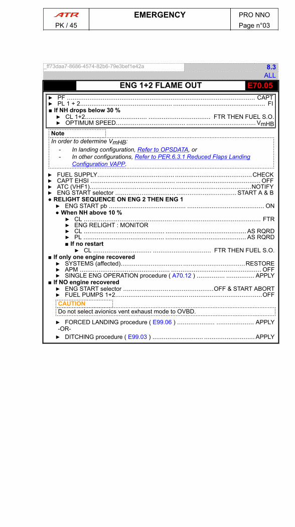
_ff73daa7-8686-4574-82b6-79e3bef1e42a 8.3ALL
- E70.05ENG 1+2 FLAME OUT▶ PF .................................................................................................... CAPT▶ PL 1 + 2................................................. ................................................. FI■ If NH drops below 30 %▶ CL 1+2................................. ................................. FTR THEN FUEL S.O.▶ OPTIMUM SPEED..................................... ..................................... VmHB
NoteIn order to determine VmHB:
- In landing configuration, Refer to OPSDATA, or- In other configurations, Refer to PER.6.3.1 Reduced Flaps Landing
Configuration VAPP.
▶ FUEL SUPPLY......................................... .........................................CHECK▶ CAPT EHSI ............................................. ............................................. OFF▶ ATC (VHF1)......................................................................................NOTIFY▶ ENG START selector ................................ ................................ START A & B● RELIGHT SEQUENCE ON ENG 2 THEN ENG 1▶ ENG START pb ......................................... ......................................... ON● When NH above 10 %▶ CL .............................................................................................. FTR▶ ENG RELIGHT : MONITOR▶ CL ........................................... ........................................... AS RQRD▶ PL ........................................... ........................................... AS RQRD■ If no restart▶ CL ............................... ............................... FTR THEN FUEL S.O.
■ If only one engine recovered▶ SYSTEMS (affected)................................. .................................RESTORE▶ APM ................................................ ................................................ OFF▶ SINGLE ENG OPERATION procedure ( A70.12 ) ............... ............... APPLY
■ If NO engine recovered▶ ENG START selector ................................................OFF & START ABORT▶ FUEL PUMPS 1+2..............................................................................OFFCAUTIONDo not select avionics vent exhaust mode to OVBD.
▶ FORCED LANDING procedure ( E99.06 ) .................... .................... APPLY-OR-▶ DITCHING procedure ( E99.03 ) ........................... ........................... APPLY
EMERGENCY PRO NNOPK / 45 Page n°03

PAGE
INTENTIONALLY
LEFT BLANK
EMERGENCY PRO NNOPK / 45 Page n°04
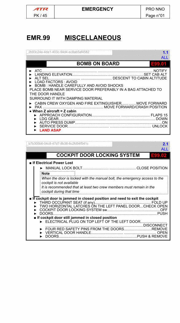
EMR.99 MISCELLANEOUS
_2b93c24e-4da1-403c-94d4-ec8ab5af4582 1.1ALL
- E99.01BOMB ON BOARD▶ ATC................................................ ................................................ NOTIFY▶ LANDING ELEVATION..............................................................SET CAB ALT▶ ALT SEL........................... ........................... DESCENT TO CABIN ALTITUDE▶ LOAD FACTORS : AVOID▶ BOMB : HANDLE CAREFULLY AND AVOID SHOCKSPLACE BOMB NEAR SERVICE DOOR PREFERABLY IN A BAG ATTACHED TOTHE DOOR HANDLESURROUND IT WITH DAMPING MATERIAL▶ CABIN CREW OXYGEN AND FIRE EXTINGUISHER...... ...... MOVE FORWARD▶ PAX .......................... .......................... MOVE FORWARD/CRASH POSITION● When Z aircraft = Z cabin▶ APPROACH CONFIGURATION......................... ......................... FLAPS 15▶ LDG GEAR.......................................... .......................................... DOWN▶ AUTO PRESS DUMP............................................................................ON▶ SERVICE DOOR.................................... .................................... UNLOCK▶ LAND ASAP
_b7b305b6-04c8-47d7-8b38-6c2fd94f541c 2.1ALL
- E99.02COCKPIT DOOR LOCKING SYSTEM■ If Electrical Power Lost
▶ MANUAL LOCK BOLT....................... ....................... CLOSE POSITIONNoteWhen the door is locked with the manual bolt, the emergency access to thecockpit is not availableIt is recommended that at least two crew members must remain in thecockpit during that time
■ If cockpit door is jammed in closed position and need to exit the cockpit▶ THIRD OCCUPANT SEAT (if any)........................ ........................ FOLD UP▶ TWO HORIZONTAL LATCHES ON THE LEFT PANEL DOOR...CHECK OPEN▶ COCKPIT DOOR LOCKING SYSTEM sw..............................................OFF▶ DOORS............................................. ............................................. PUSH■ If cockpit door still jammed in closed position▶ ELECTRICAL PLUG ON TOP LEFT OF THE LEFT DOOR.......................
.....................................................................................DISCONNECT▶ FOUR RED SAFETY PINS FROM THE DOORS........................REMOVE▶ VERTICAL DOOR HANDLE............................ ............................ OPEN▶ DOORS....................................................................PUSH & REMOVE
EMERGENCY PRO NNOPK / 45 Page n°01
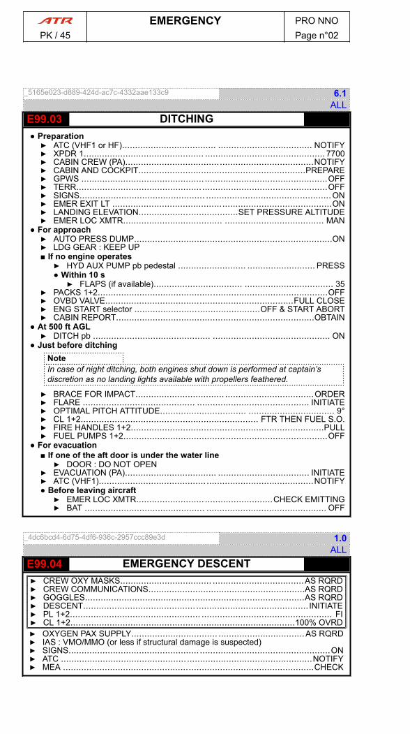
_5165e023-d889-424d-ac7c-4332aae133c9 6.1ALL
- E99.03 DITCHING● Preparation▶ ATC (VHF1 or HF).................................... .................................... NOTIFY▶ XPDR 1.............................................. .............................................. 7700▶ CABIN CREW (PA)........................................................................NOTIFY▶ CABIN AND COCKPIT................................................................PREPARE▶ GPWS ..............................................................................................OFF▶ TERR................................................................................................OFF▶ SIGNS................................................ ................................................ON▶ EMER EXIT LT ....................................................................................ON▶ LANDING ELEVATION......................................SET PRESSURE ALTITUDE▶ EMER LOC XMTR...................................... ...................................... MAN
● For approach▶ AUTO PRESS DUMP............................................................................ON▶ LDG GEAR : KEEP UP■ If no engine operates▶ HYD AUX PUMP pb pedestal .......................... .......................... PRESS● Within 10 s▶ FLAPS (if available).................................. .................................. 35
▶ PACKS 1+2........................................................................................OFF▶ OVBD VALVE........................................................................FULL CLOSE▶ ENG START selector ................................................OFF & START ABORT▶ CABIN REPORT............................................................................OBTAIN
● At 500 ft AGL▶ DITCH pb ............................................. ............................................. ON
● Just before ditchingNoteIn case of night ditching, both engines shut down is performed at captain’sdiscretion as no landing lights available with propellers feathered.
▶ BRACE FOR IMPACT.................................. ..................................ORDER▶ FLARE ........................................... ........................................... INITIATE▶ OPTIMAL PITCH ATTITUDE................................. ................................. 9°▶ CL 1+2.................................................................... FTR THEN FUEL S.O.▶ FIRE HANDLES 1+2..........................................................................PULL▶ FUEL PUMPS 1+2..............................................................................OFF
● For evacuation■ If one of the aft door is under the water line▶ DOOR : DO NOT OPEN
▶ EVACUATION (PA)................................... ................................... INITIATE▶ ATC (VHF1)..................................................................................NOTIFY● Before leaving aircraft▶ EMER LOC XMTR....................................................CHECK EMITTING▶ BAT .............................................. .............................................. OFF
_4dc6bcd4-6d75-4df6-936c-2957ccc89e3d 1.0ALL
- E99.04 EMERGENCY DESCENT▶ CREW OXY MASKS................................... ...................................AS RQRD▶ CREW COMMUNICATIONS............................................................AS RQRD▶ GOGGLES....................................................................................AS RQRD▶ DESCENT........................................... ........................................... INITIATE▶ PL 1+2.................................................. .................................................. FI▶ CL 1+2......................................................................................100% OVRD▶ OXYGEN PAX SUPPLY................................. .................................AS RQRD▶ IAS : VMO/MMO (or less if structural damage is suspected)▶ SIGNS....................................................................................................ON▶ ATC ................................................................................................NOTIFY▶ MEA ................................................................................................CHECK
EMERGENCY PRO NNOPK / 45 Page n°02
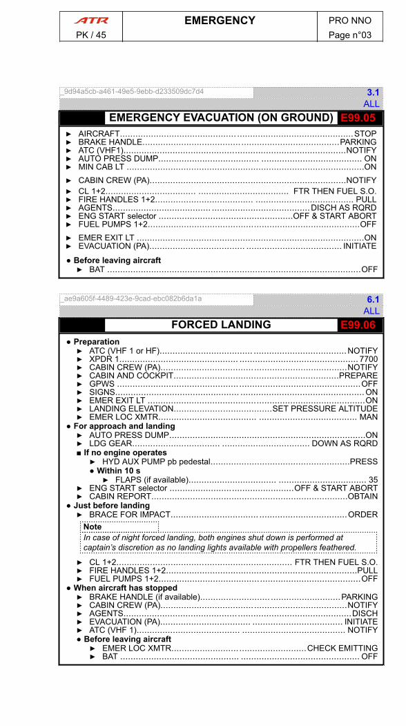
_9d94a5cb-a461-49e5-9ebb-d233509dc7d4 3.1ALL
- E99.05EMERGENCY EVACUATION (ON GROUND)▶ AIRCRAFT............................................. .............................................STOP▶ BRAKE HANDLE............................................................................PARKING▶ ATC (VHF1)......................................................................................NOTIFY▶ AUTO PRESS DUMP....................................... ....................................... ON▶ MIN CAB LT ............................................................................................ON▶ CABIN CREW (PA)............................................................................NOTIFY▶ CL 1+2................................... ................................... FTR THEN FUEL S.O.▶ FIRE HANDLES 1+2...................................... ...................................... PULL▶ AGENTS...................................... ......................................DISCH AS RQRD▶ ENG START selector ....................................................OFF & START ABORT▶ FUEL PUMPS 1+2..................................................................................OFF▶ EMER EXIT LT ........................................................................................ON▶ EVACUATION (PA)..................................... ..................................... INITIATE
● Before leaving aircraft▶ BAT ..................................................................................................OFF
_ae9a605f-4489-423e-9cad-ebc082b6da1a 6.1ALL
- E99.06FORCED LANDING● Preparation▶ ATC (VHF 1 or HF).................................... ....................................NOTIFY▶ XPDR 1.............................................. .............................................. 7700▶ CABIN CREW (PA)........................................................................NOTIFY▶ CABIN AND COCKPIT................................................................PREPARE▶ GPWS ..............................................................................................OFF▶ SIGNS................................................ ................................................ON▶ EMER EXIT LT ....................................................................................ON▶ LANDING ELEVATION......................................SET PRESSURE ALTITUDE▶ EMER LOC XMTR...................................... ...................................... MAN
● For approach and landing▶ AUTO PRESS DUMP............................................................................ON▶ LDG GEAR.................................. .................................. DOWN AS RQRD■ If no engine operates▶ HYD AUX PUMP pb pedestal......................................................PRESS● Within 10 s▶ FLAPS (if available).................................. .................................. 35
▶ ENG START selector ................................................OFF & START ABORT▶ CABIN REPORT............................................................................OBTAIN
● Just before landing▶ BRACE FOR IMPACT.................................. ..................................ORDER
NoteIn case of night forced landing, both engines shut down is performed atcaptain’s discretion as no landing lights available with propellers feathered.
▶ CL 1+2.................................................................... FTR THEN FUEL S.O.▶ FIRE HANDLES 1+2..........................................................................PULL▶ FUEL PUMPS 1+2..............................................................................OFF
● When aircraft has stopped▶ BRAKE HANDLE (if available)........................... ...........................PARKING▶ CABIN CREW (PA)........................................................................NOTIFY▶ AGENTS........................................................................................DISCH▶ EVACUATION (PA)................................... ................................... INITIATE▶ ATC (VHF 1)........................................ ........................................ NOTIFY● Before leaving aircraft▶ EMER LOC XMTR....................................................CHECK EMITTING▶ BAT .............................................. .............................................. OFF
EMERGENCY PRO NNOPK / 45 Page n°03

_60d93efb-5e98-4a78-80e2-05501a99087e 6.1ALL
- E99.08 SEVERE ICING▶ IAS : ICING BUG + 30 kt (or ICING BUG IF FLAPS 15 EXTENDED)▶ PWR MGT ............................................. ............................................. MCT▶ PL 1+2............................................................................................ADJUST▶ CL 1+2.................................................................................... 100 % OVRD▶ DESCENT........................................... ........................................... INITIATE▶ MEA / RECOMMENDED MAXIMUM ICING FLIGHT LEVEL......... ......... CHECK
CAUTIONFirmly hold control column and wheel to avoid non-expected aircraft movementsat AP disengagement
▶ AP ........................................... ........................................... DISENGAGE
■ If not able to accelerate and maintain IAS above ICING BUG + 30 kt with flaps0
- OR -■ If not able to accelerate and maintain IAS above ICING BUG with flaps 15▶ LOW BANK........................................................................................SET
▶ SEVERE ICING CONDITION.............................. ..............................ESCAPE▶ ATC ................................................................................................NOTIFY■ If abnormal aircraft roll behavior▶ STALL procedure ( E99.09 ) .............................. ..............................APPLY
● As long as aircraft is not clear of ice▶ FLAPS : DO NOT RETRACT● For landing▶ APPROACH CONFIGURATION ...................... ...................... FLAPS 15HIGH BANK CAN BE SET▶ REDUCED FLAPS LANDING procedure ( A27.05 ) ........... ........... APPLY
NoteRefer to PRO.NNO.ABN.30.5.3.A30.16 SEVERE ICING DETECTION forinformation on severe icing indications.
_58995808-e615-41b3-8bb9-b0f2175ed226 2.1ALL
- E99.09 STALL▶ CONTROL COLUMN..................................... ..................................... PUSH▶ ENG PWR ..................................................................................INCREASE■ If FLAPS 0▶ FLAPS..............................................................................EXTEND TO 15
▶ BANK....................................................................................WINGS LEVELWARNING▶ STICK PUSHER ACTIVATION : NO OPPOSITE ACTION▶ FLAPS : DO NOT RETRACT▶ RUDDER : USE WITH CARE
▶ ATC ................................................................................................NOTIFY● When out of stall▶ FLIGHT PATH............................ ............................RECOVER SMOOTHLY
EMERGENCY PRO NNOPK / 45 Page n°04

_17126473-ecbb-4038-b964-be6d1df70cb1 5.2ALL
- E99.10UNRELIABLE AIRSPEED INDICATIONCAUTIONUnreliable airspeed indication procedure has to be applied only when the threeairspeed sources (both ADC and IESI) indications differ.
▶ AP/YD ................................................ ................................................ OFF▶ FD .................................................................................................... STBY▶ PITCH : MAINTAIN▶ TQ : MAINTAIN■ If at takeoff or GA below 1 500 ft▶ PITCH.......................................................................... 8 ° IMMEDIATELY
▶ ICING CONDITIONS........................................................................ESCAPE▶ VOLCANIC ASHES CONDITIONS.......................... ..........................ESCAPE
▶ AP and/or YD USE : PROHIBITED▶ PROBES HTG ...................................... ......................................CHECK ON▶ DE/ANTI ICING............................................................................CHECK ON▶ APM .................................................. .................................................. OFFSTALL ALARM STILL RELIABLE▶ GPS SPEED INFORMATION (IF AVAILABLE)..................... ..................... USE● Takeoff phase, at or above acceleration altitude▶ ALTITUDE : MAINTAIN AT LEAST 20 s▶ FLAPS................................................. ................................................. 0▶ PITCH................................................ ................................................ 8 °LAND AT NEAREST SUITABLE AIRPORT
● Climb▶ TLU sw ........................................... ........................................... LO SPD▶ PWR MGT ........................................................................................ CLB▶ PL 1+2..........................................................................................NOTCH▶ PITCH............................. .............................ADJUST FOLLOWING TABLE
Altitude (ft) 5 000 10 000 15 000 20 000
Normal conditions pitch 8 ° 6 ° 5 ° 4 °
Icing conditions pitch 7 ° 5 ° 4 ° 3 °
● Cruise▶ ALTITUDE : MAINTAIN▶ TLU sw ........................................................................................ HI SPD
NoteAverage pitch around 0 ° at cruise speed.
▶ PWR MGT ........................................... ........................................... CRZ▶ PL 1+2..........................................................................................NOTCH
● Descent▶ TLU sw ........................................................................................ HI SPD▶ PITCH : MAINTAIN AT -2.5 °▶ PL 1+2......................................................................ADJUST TO 30 % TQ
● Initial ApproachCAUTIONPerform transition from clean to LDG configuration in level flight. Refer toALTIMETER.If possible, maintain level flight during 30 s between each configuration update.
▶ TLU sw ........................................... ........................................... LO SPD▶ TQ ............................... ............................... ADJUST FOLLOWING TABLE
EMERGENCY PRO NNOPK / 45 Page n°05
cont'd…

Aircraft configuration - Averagespeed
TQ (Altitude of 3 000 ft)
14 T 16 T 18T
FLAPS 0 - 180 kt 35 % 40 % 45 %
FLAPS 15 - 150 kt 30 % 35 % 40 %
FLAPS 35 - 130 kt 45 % 45 % 50 %
▶ FLAPS..................................................................................................15▶ LDG GEAR.......................................... .......................................... DOWN▶ PWR MGT ............................................. ............................................. TO▶ FLAPS..................................................................................................35
● Final Approach▶ PL 1+2..................................... ..................................... ADJUST 35 % TQ▶ Before Landing procedure ( 21 ) ........................... ........................... APPLY
NoteSet an average pitch of -5 ° for a 3 ° slope approach.
EMERGENCY PRO NNOPK / 45 Page n°06
cont'd…

AIR CONDITIONINGAlert Procedure Code
DUCT 1(2) OVHT A21.01
PACK 1(2) VALVE FAULT A21.02
PACK 1+2 VALVES FAULT A21.03
RECIRC FAN 1(2) FAULT A21.06
AVIONICS VENT EXHAUST MODE FAULT A21.08
OVBD VALVE FAULT A21.09
AUTO PRESS FAULT A21.10
EXCESS CAB ALT A21.13
EXCESS CAB DELTA P A21.14
AUTOPILOTAlert Procedure Code
ABNORMAL FLIGHT CHARACTERISTICS INROLL
A22.01
ADU FAILURE A22.02
AILERON MISTRIM (ADU MESSAGE) A22.03
AP PITCH TRIM FAIL (ADU MESSAGE) A22.04
DADC DATA INVALID (ADU MESSAGE) A22.05
EXCESSIVE LATERAL TRIM REQUIRED A22.10
PITCH MISTRIM (ADU MESSAGE) A22.13
COMMUNICATIONSAlert Procedure Code
AUDIO SEL 1(2) FAULT A23.02
XPDR FAULT A23.05
FOLLOWING FAILURES PRO NNOPK / 45 Page n°01
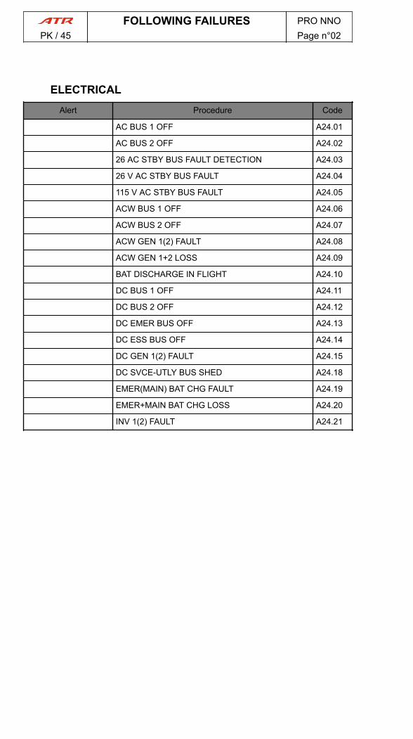
ELECTRICALAlert Procedure Code
AC BUS 1 OFF A24.01
AC BUS 2 OFF A24.02
26 AC STBY BUS FAULT DETECTION A24.03
26 V AC STBY BUS FAULT A24.04
115 V AC STBY BUS FAULT A24.05
ACW BUS 1 OFF A24.06
ACW BUS 2 OFF A24.07
ACW GEN 1(2) FAULT A24.08
ACW GEN 1+2 LOSS A24.09
BAT DISCHARGE IN FLIGHT A24.10
DC BUS 1 OFF A24.11
DC BUS 2 OFF A24.12
DC EMER BUS OFF A24.13
DC ESS BUS OFF A24.14
DC GEN 1(2) FAULT A24.15
DC SVCE-UTLY BUS SHED A24.18
EMER(MAIN) BAT CHG FAULT A24.19
EMER+MAIN BAT CHG LOSS A24.20
INV 1(2) FAULT A24.21
FOLLOWING FAILURES PRO NNOPK / 45 Page n°02
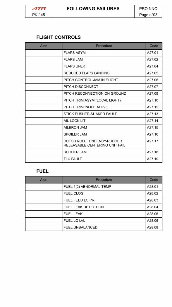
FLIGHT CONTROLSAlert Procedure Code
FLAPS ASYM A27.01
FLAPS JAM A27.02
FLAPS UNLK A27.04
REDUCED FLAPS LANDING A27.05
PITCH CONTROL JAM IN FLIGHT A27.06
PITCH DISCONNECT A27.07
PITCH RECONNECTION ON GROUND A27.09
PITCH TRIM ASYM (LOCAL LIGHT) A27.10
PITCH TRIM INOPERATIVE A27.12
STICK PUSHER-SHAKER FAULT A27.13
AIL LOCK LIT A27.14
AILERON JAM A27.15
SPOILER JAM A27.16
DUTCH ROLL TENDENCY-RUDDERRELEASABLE CENTERING UNIT FAIL
A27.17
RUDDER JAM A27.18
TLU FAULT A27.19
FUELAlert Procedure Code
FUEL 1(2) ABNORMAL TEMP A28.01
FUEL CLOG A28.02
FUEL FEED LO PR A28.03
FUEL LEAK DETECTION A28.04
FUEL LEAK A28.05
FUEL LO LVL A28.06
FUEL UNBALANCED A28.08
FOLLOWING FAILURES PRO NNOPK / 45 Page n°03

HYDRAULIC SYSTEMAlert Procedure Code
HYD BLUE (GREEN) LO LVL A29.01
HYD BLUE (GREEN) LO PR A29.02
HYD BLUE (GREEN) OVHT A29.03
HYD BLUE AND GREEN PUMPS LOSS A29.04
HYD BLUE AND GREEN SYS LOSS A29.05
HYD AUX LO PR A29.06
HYD AUX OVHT A29.07
ICE AND RAINAlert Procedure Code
ANTI ICING HORNS 1(2) FAULT A30.01
ANTI ICING PROP 1(2) FAULT A30.02
AFR AIR BLEED FAULT A30.05
DE-ANTI ICING MODE SEL AUTO FAULT A30.06
DE ICING AIRFRAME FAULT A30.07
DE ICING MODE SEL FAULT A30.08
DE ICING ENG 1(2) FAULT A30.09
ICE DETECT FAULT A30.10
PROBES HTG FAILURE A30.11
SIDE WINDOW HTG FAULT A30.12
WINDSHIELD HTG FAULT A30.13
APM FAULT A30.14
DEGRADED PERF A30.15
SEVERE ICING DETECTION A30.16
INCREASE SPEED A30.17
FOLLOWING FAILURES PRO NNOPK / 45 Page n°04

MFCAlert Procedure Code
MFC 1A FAULT A31.01
MFC 1B FAULT A31.02
MFC 2A Fault A31.03
MFC 2B FAULT A31.04
MFC 1A+1B FAULT A31.05
MFC 1A+2A FAULT A31.06
MFC 1A+2B FAULT A31.07
MFC 1B+2A FAULT A31.08
MFC 1B+2B FAULT A31.09
MFC 2A+2B FAULT A31.10
LANDING GEARAlert Procedure Code
ANTISKID FAULT A32.01
BRK TEMP HOT A32.02
LDG GEAR GRAVITY EXTENSION A32.03
LDG GEAR RETRACTION NOT POSSIBLE A32.04
LDG GEAR UNSAFE INDICATION A32.05
LANDING WITH ABNORMAL LDG GEAR A32.06
NAVIGATIONAlert Procedure Code
ADC 1(2) FAILURE A34.01
ADC 1+2 FAILURE A34.02
ADC SW FAULT A34.03
AHRS A - ERECT FAIL A34.04
AHRS 1(2) FAILURE A34.05
EFIS COMP A34.10
LOSS OF RADIO ALTIMETER INFORMATION A34.48
CRT FAIL A34.52
EFIS FAILURE A34.53
SGU FAIL A34.54
FOLLOWING FAILURES PRO NNOPK / 45 Page n°05
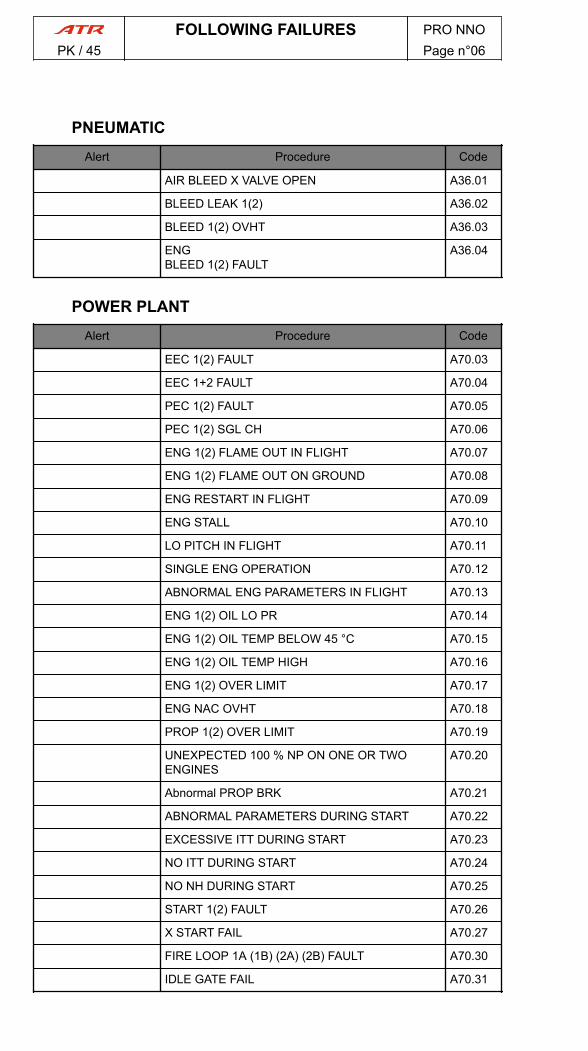
PNEUMATICAlert Procedure Code
AIR BLEED X VALVE OPEN A36.01
BLEED LEAK 1(2) A36.02
BLEED 1(2) OVHT A36.03
ENGBLEED 1(2) FAULT
A36.04
POWER PLANTAlert Procedure Code
EEC 1(2) FAULT A70.03
EEC 1+2 FAULT A70.04
PEC 1(2) FAULT A70.05
PEC 1(2) SGL CH A70.06
ENG 1(2) FLAME OUT IN FLIGHT A70.07
ENG 1(2) FLAME OUT ON GROUND A70.08
ENG RESTART IN FLIGHT A70.09
ENG STALL A70.10
LO PITCH IN FLIGHT A70.11
SINGLE ENG OPERATION A70.12
ABNORMAL ENG PARAMETERS IN FLIGHT A70.13
ENG 1(2) OIL LO PR A70.14
ENG 1(2) OIL TEMP BELOW 45 °C A70.15
ENG 1(2) OIL TEMP HIGH A70.16
ENG 1(2) OVER LIMIT A70.17
ENG NAC OVHT A70.18
PROP 1(2) OVER LIMIT A70.19
UNEXPECTED 100 % NP ON ONE OR TWOENGINES
A70.20
Abnormal PROP BRK A70.21
ABNORMAL PARAMETERS DURING START A70.22
EXCESSIVE ITT DURING START A70.23
NO ITT DURING START A70.24
NO NH DURING START A70.25
START 1(2) FAULT A70.26
X START FAIL A70.27
FIRE LOOP 1A (1B) (2A) (2B) FAULT A70.30
IDLE GATE FAIL A70.31
FOLLOWING FAILURES PRO NNOPK / 45 Page n°06

MISCELLANEOUSAlert Procedure Code
COCKPIT DOOR CONTROL PANEL FAULT A99.01
DOORS UNLK IN FLIGHT A99.02
OXYGEN LO PR A99.03
SMK DET FANS FAULT A99.04
COCKPIT WINDOW CRACKED A99.05
VOLCANIC ASH ENCOUNTER A99.06
FOLLOWING FAILURES PRO NNOPK / 45 Page n°07

PAGE
INTENTIONALLY
LEFT BLANK
FOLLOWING FAILURES PRO NNOPK / 45 Page n°08

_b47cb9f6-a287-4938-a109-f9af2e65710c 4.2ALL
A21.01DUCT 1(2) OVHT▶ TEMP SEL (affected side)...................................................................... MAN▶ COMPT TEMP selector (affected side)......................... ......................... COLD▶ DUCT TEMPERATURE : MONITORNoteMake sure DUCT temperature remains positive to avoid possible pack turbinedamage.
■ If alert persists▶ PACK VALVE (affected side)................................ ................................ OFF▶ MAX FL : 200/MEA● At high altitude▶ LARGE RAPID POWER CHANGES : AVOID
_2920dd9e-f5d2-4839-a270-df0cfca9ec64 2.5ALL
A21.02PACK 1(2) VALVE FAULT▶ PACK VALVE (affected side).................................. ..................................OFF▶ MAX FL : 200/MEA● At high altitude▶ LARGE RAPID POWER CHANGE : AVOID
_87f45607-b5f9-41b1-815e-dc8f8432eac6 2.0ALL
A21.03PACK 1+2 VALVES FAULT▶ MAX FL : 100 or MEA▶ MAX FLIGHT TIME : 80 min● When ΔP < 1 psi▶ OVBD VALVE..........................................................................FULL OPEN▶ CAB PRESS RATE knob ....................................9 O’CLOCK (MAN position)▶ CAB PRESS MODE SEL ................................. ................................. MAN▶ CAB PRESS RATE knob .................................................. MAX INCREASE
_b7c1277a-7829-4387-8474-ef7002aaf06d 1.1ALL
A21.06RECIRC FAN 1(2) FAULT▶ RECIRC FAN (affected side)....................................................................OFF
_dc18174f-d87b-4047-9c62-5976026493cc 0.1ALL
A21.08AVIONICS VENT EXHAUST MODE FAULT▶ EXHAUST MODE........................................ ........................................OVBD
FOLLOWING FAILURES PRO NNO
PK / 45 AIR CONDITIONING Page n°01
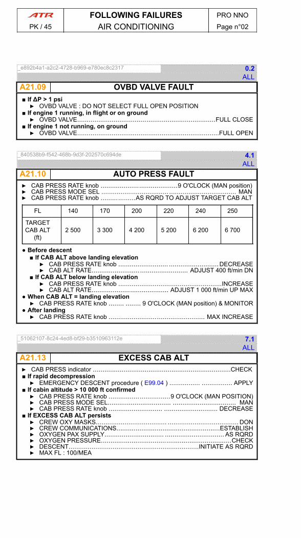
_e892b4a1-a2c2-4728-b969-e780ec8c2317 0.2ALL
A21.09 OVBD VALVE FAULT■ If ΔP > 1 psi▶ OVBD VALVE : DO NOT SELECT FULL OPEN POSITION
■ If engine 1 running, in flight or on ground▶ OVBD VALVE........................................................................FULL CLOSE
■ If engine 1 not running, on ground▶ OVBD VALVE..........................................................................FULL OPEN
_840538b9-f542-468b-9d3f-202570c694de 4.1ALL
A21.10 AUTO PRESS FAULT▶ CAB PRESS RATE knob ........................................9 O'CLOCK (MAN position)▶ CAB PRESS MODE SEL ................................... ................................... MAN▶ CAB PRESS RATE knob ..................AS RQRD TO ADJUST TARGET CAB ALT
FL 140 170 200 220 240 250
TARGETCAB ALT
(ft)2 500 3 300 4 200 5 200 6 200 6 700
● Before descent■ If CAB ALT above landing elevation▶ CAB PRESS RATE knob .......................... ..........................DECREASE▶ CAB ALT RATE.................................................. ADJUST 400 ft/min DN
■ If CAB ALT below landing elevation▶ CAB PRESS RATE knob ......................................................INCREASE▶ CAB ALT RATE........................................ ADJUST 1 000 ft/min UP MAX
● When CAB ALT = landing elevation▶ CAB PRESS RATE knob ........ ........ 9 O'CLOCK (MAN position) & MONITOR
● After landing▶ CAB PRESS RATE knob .................................................. MAX INCREASE
_51062107-8c24-4ed8-bf29-b3510963112e 7.1ALL
A21.13 EXCESS CAB ALT▶ CAB PRESS indicator ........................................................................CHECK■ If rapid decompression▶ EMERGENCY DESCENT procedure ( E99.04 ) ................ ................ APPLY
■ If cabin altitude > 10 000 ft confirmed▶ CAB PRESS RATE knob ................................9 O'CLOCK (MAN POSITION)▶ CAB PRESS MODE SEL................................. ................................. MAN▶ CAB PRESS RATE knob ............................ ............................ DECREASE
■ If EXCESS CAB ALT persists▶ CREW OXY MASKS..................................... ..................................... DON▶ CREW COMMUNICATIONS......................................................ESTABLISH▶ OXYGEN PAX SUPPLY............................... ............................... AS RQRD▶ OXYGEN PRESSURE....................................................................CHECK▶ DESCENT....................................................................INITIATE AS RQRD▶ MAX FL : 100/MEA
FOLLOWING FAILURES PRO NNO
PK / 45 AIR CONDITIONING Page n°02

_40fe8e77-b971-42fb-8877-9a6fa6f918a7 4.3ALL
A21.14EXCESS CAB DELTA P▶ CAB PRESS RATE knob.................... .................... 9 O'CLOCK (MAN position)▶ CAB PRESS MODE SEL ................................... ................................... MAN▶ CAB PRESS RATE knob........................... ........................... MAX INCREASE■ If EXCESS CAB DELTA P persists▶ DESCENT ..................................................................................INITIATE▶ MAX FL : 100/MEA
NoteClosing of the pack valves may trigger EXCESS CAB ALT alert
▶ PACK VALVE 1+2....................................... ....................................... OFF▶ MAX FLIGHT TIME : 80 min● When ΔP < 1 psi▶ OVBD VALVE.................................. .................................. FULL OPEN
FOLLOWING FAILURES PRO NNO
PK / 45 AIR CONDITIONING Page n°03
PAGE
INTENTIONALLY
LEFT BLANK
FOLLOWING FAILURES PRO NNO
PK / 45 AIR CONDITIONING Page n°04
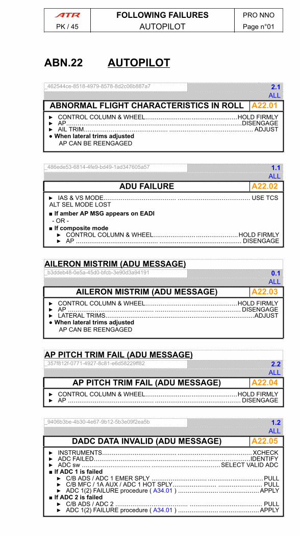
ABN.22 AUTOPILOT
_462544ce-8518-4979-8578-8d2c06b887a7 2.1ALL
A22.01ABNORMAL FLIGHT CHARACTERISTICS IN ROLL▶ CONTROL COLUMN & WHEEL................................................HOLD FIRMLY▶ AP............................................................................................DISENGAGE▶ AIL TRIM............................................ ............................................ ADJUST● When lateral trims adjusted
AP CAN BE REENGAGED
_486ede53-6814-4fe9-bd49-1ad347605a57 1.1ALL
A22.02ADU FAILURE▶ IAS & VS MODE...................................... ...................................... USE TCSALT SEL MODE LOST■ If amber AP MSG appears on EADI- OR -
■ If composite mode▶ CONTROL COLUMN & WHEEL...................... ......................HOLD FIRMLY▶ AP ........................................... ........................................... DISENGAGE
AILERON MISTRIM (ADU MESSAGE)_b3ddeb48-0e5a-45d0-bfcb-3e90d3a94191 0.1
ALL A22.03AILERON MISTRIM (ADU MESSAGE)
▶ CONTROL COLUMN & WHEEL................................................HOLD FIRMLY▶ AP ............................................. ............................................. DISENGAGE▶ LATERAL TRIMS..............................................................................ADJUST● When lateral trims adjusted
AP CAN BE REENGAGED
AP PITCH TRIM FAIL (ADU MESSAGE)_357f812f-0771-4927-8c81-e6d58229ff82 2.2
ALL A22.04AP PITCH TRIM FAIL (ADU MESSAGE)
▶ CONTROL COLUMN & WHEEL................................................HOLD FIRMLY▶ AP ............................................. ............................................. DISENGAGE
_9406b3be-4b30-4e67-9b12-5b3e09f2ea5b 1.2ALL
A22.05DADC DATA INVALID (ADU MESSAGE)▶ INSTRUMENTS....................................... .......................................XCHECK▶ ADC FAILED..................................................................................IDENTIFY▶ ADC sw .................................... ....................................SELECT VALID ADC■ If ADC 1 is failed▶ C/B ADS / ADC 1 EMER SPLY ............................. .............................PULL▶ C/B MFC / 1A AUX / ADC 1 HOT SPLY....................... ....................... PULL▶ ADC 1(2) FAILURE procedure ( A34.01 ) ..................... .....................APPLY
■ If ADC 2 is failed▶ C/B ADS / ADC 2 ...................................... ...................................... PULL▶ ADC 1(2) FAILURE procedure ( A34.01 ) ..................... .....................APPLY
FOLLOWING FAILURES PRO NNO
PK / 45 AUTOPILOT Page n°01
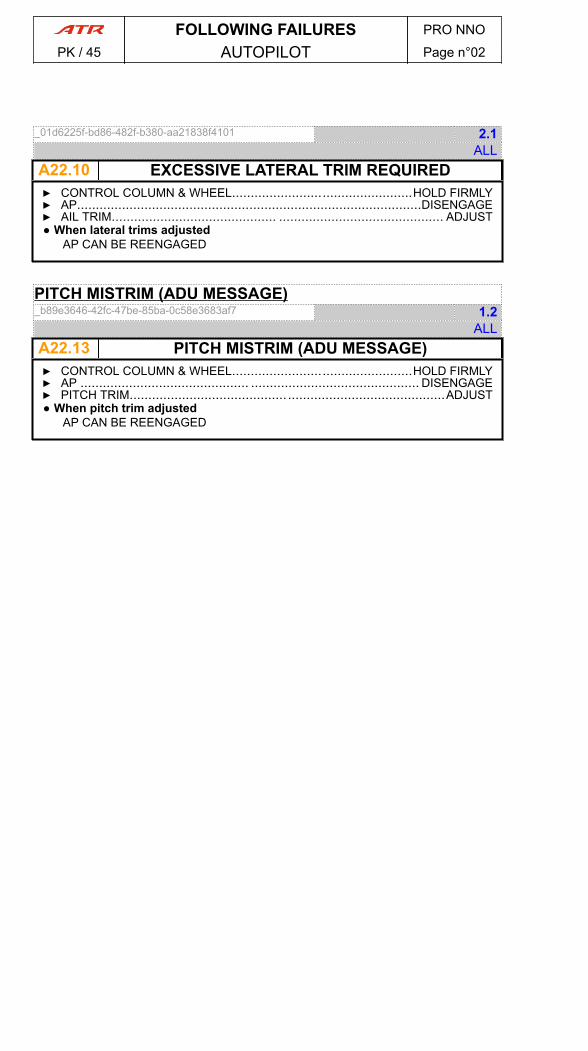
_01d6225f-bd86-482f-b380-aa21838f4101 2.1ALL
A22.10 EXCESSIVE LATERAL TRIM REQUIRED▶ CONTROL COLUMN & WHEEL................................................HOLD FIRMLY▶ AP............................................................................................DISENGAGE▶ AIL TRIM............................................ ............................................ ADJUST● When lateral trims adjusted
AP CAN BE REENGAGED
PITCH MISTRIM (ADU MESSAGE)_b89e3646-42fc-47be-85ba-0c58e3683af7 1.2
ALL A22.13 PITCH MISTRIM (ADU MESSAGE)▶ CONTROL COLUMN & WHEEL................................................HOLD FIRMLY▶ AP ............................................. ............................................. DISENGAGE▶ PITCH TRIM.......................................... ..........................................ADJUST● When pitch trim adjusted
AP CAN BE REENGAGED
FOLLOWING FAILURES PRO NNO
PK / 45 AUTOPILOT Page n°02

_0761eb38-2e41-46ba-a8c1-8082b30a5257 0.3ALL
A23.02AUDIO SEL 1(2) FAULT▶ AUDIO SEL (affected)............................................................................ALTN
_31a415ef-b298-4788-b758-e5b945db3886 2.0ALL
A23.05XPDR FAULT▶ XPDR.................................. .................................. CHANGE ACTIVE XPDR
FOLLOWING FAILURES PRO NNO
PK / 45 COMMUNICATIONS Page n°01

PAGE
INTENTIONALLY
LEFT BLANK
FOLLOWING FAILURES PRO NNO
PK / 45 COMMUNICATIONS Page n°02
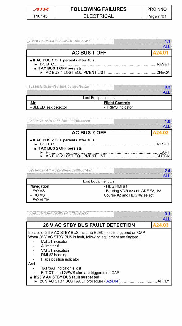
_78b3063d-3f93-4059-96a5-945aae8b549c 1.1ALL
A24.01AC BUS 1 OFF■ If AC BUS 1 OFF persists after 10 s▶ DC BTC............................................ ............................................ RESET■ If AC BUS 1 OFF persists▶ AC BUS 1 LOST EQUIPMENT LIST............................................CHECK
_5d33d6fa-2b3a-4f5c-8ac6-9e109af6e82b 0.3ALL
Lost Equipment ListAir- BLEED leak detector
Flight Controls- TRIMS indicator
_3e222127-ae2b-4167-84e1-93f3f04445d0 1.0ALL
A24.02AC BUS 2 OFF■ If AC BUS 2 OFF persists after 10 s▶ DC BTC............................................ ............................................ RESET■ If AC BUS 2 OFF persists▶ PF..............................................................................................CAPT▶ AC BUS 2 LOST EQUIPMENT LIST............................................CHECK
_8991e462-d471-4092-99ee-25209b5d74a7 2.4ALL
Lost Equipment ListNavigation- F/O ASI- F/O VSI- F/O ALTM
- HDG RMI #1- Bearing VOR #2 and ADF #2, 1/2Course #2 and HDG #2 select
_b8fe0cc9-7f0e-4698-85fe-4f873a0e3e65 0.1ALL
A24.0326 V AC STBY BUS FAULT DETECTIONIn case of 26 V AC STBY BUS fault, no ELEC alert is triggered on CAP.When 26 V AC STBY BUS is fault, following equipment are flagged :
- IAS #1 indicator- Altimeter #1- V/S #1 indication- RMI #2 heading- Flaps position indicator
And- TAT/SAT indicator is lost- FLT CTL and GPWS alert are triggered on CAP
■ If 26 V AC STBY BUS fault suspected:▶ 26 V AC STBY BUS FAULT procedure ( A24.04 ) ............... ............... APPLY
FOLLOWING FAILURES PRO NNO
PK / 45 ELECTRICAL Page n°01
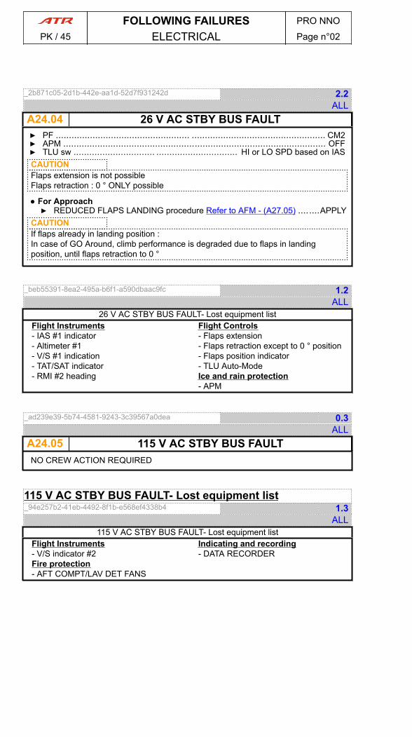
_2b871c05-2d1b-442e-aa1d-52d7f931242d 2.2ALL
A24.04 26 V AC STBY BUS FAULT▶ PF ................................................... ................................................... CM2▶ APM .................................................................................................... OFF▶ TLU sw ............................... ............................... HI or LO SPD based on IASCAUTIONFlaps extension is not possibleFlaps retraction : 0 ° ONLY possible
● For Approach▶ REDUCED FLAPS LANDING procedure Refer to AFM - (A27.05) ........APPLY
CAUTIONIf flaps already in landing position :In case of GO Around, climb performance is degraded due to flaps in landingposition, until flaps retraction to 0 °
_beb55391-8ea2-495a-b6f1-a590dbaac9fc 1.2ALL
26 V AC STBY BUS FAULT- Lost equipment listFlight Instruments- IAS #1 indicator- Altimeter #1- V/S #1 indication- TAT/SAT indicator- RMI #2 heading
Flight Controls- Flaps extension- Flaps retraction except to 0 ° position- Flaps position indicator- TLU Auto-ModeIce and rain protection- APM
_ad239e39-5b74-4581-9243-3c39567a0dea 0.3ALL
A24.05 115 V AC STBY BUS FAULTNO CREW ACTION REQUIRED
115 V AC STBY BUS FAULT- Lost equipment list_94e257b2-41eb-4492-8f1b-e568ef4338b4 1.3
ALL115 V AC STBY BUS FAULT- Lost equipment list
Flight Instruments- V/S indicator #2Fire protection- AFT COMPT/LAV DET FANS
Indicating and recording- DATA RECORDER
FOLLOWING FAILURES PRO NNO
PK / 45 ELECTRICAL Page n°02

_f205b6d2-737a-41dc-800a-5cc72f96b956 4.2ALL
A24.06ACW BUS 1 OFF▶ ICING CONDITIONS : LEAVE AND AVOID▶ ICE ACCRETION : VISUALLY MONITOR▶ ACW GEN 1 ..........................................................................................OFF▶ ADC sw ................................................................................SELECT ADC 2▶ PF ........................................................................................................ F/O▶ HYD X FEED pb ......................................................................................ON▶ IAS & ALT : PERIODICALLY COMPARE WITH STBY INST▶ ACW BUS 1 LOST EQUIPMENT LIST........................ ........................ CHECK▶ AFFECTED EQUIPMENT FAULT PROCEDURES..................................APPLY■ If IAS disagree▶ DADC DATA INVALID (ADU MESSAGE) procedure ( A22.05 ) ...... ......APPLY
● After touchdown▶ TAXI : ON ENG 1+2
_0246a910-94bd-4cf8-a785-95ba2c2c1a01 2.2ALL
Lost Equipment ListCabin- LH PAX Reading LightsHydraulic- HYD BLUE PUMPIce and Rain Protection- CAPT PITOT HTG- CAPT TAT HTG- CAPT ALPHA HTG- ANTI ICING PROP 1- ANTI ICING RUD & L ELEV HORNS- CAPT WINDSHIELD HTG
Lights- Integrated Normal INST & PANELSLights- L LAND Light- Left and rear STROBES
_9ee3b1f8-89f5-4b13-baf5-ac522b89fd03 4.2ALL
A24.07ACW BUS 2 OFF▶ ICING CONDITIONS : LEAVE AND AVOID▶ ICE ACCRETION : VISUALLY MONITOR▶ ACW GEN 2 ..........................................................................................OFF▶ ADC sw ................................................................................SELECT ADC 1▶ PF .................................................. .................................................. CAPT▶ HYD X FEED pb ......................................................................................ON▶ IAS & ALT : PERIODICALLY COMPARE WITH STBY INST▶ ACW BUS 2 LOST EQUIPMENT LIST........................ ........................ CHECK▶ AFFECTED EQUIPMENT FAULT PROCEDURES..................................APPLY■ If IAS disagree▶ DADC DATA INVALID (ADU MESSAGE) procedure ( A22.05 ) ...... ......APPLY
● After touchdown▶ TAXI : ON ENG 1+2
FOLLOWING FAILURES PRO NNO
PK / 45 ELECTRICAL Page n°03
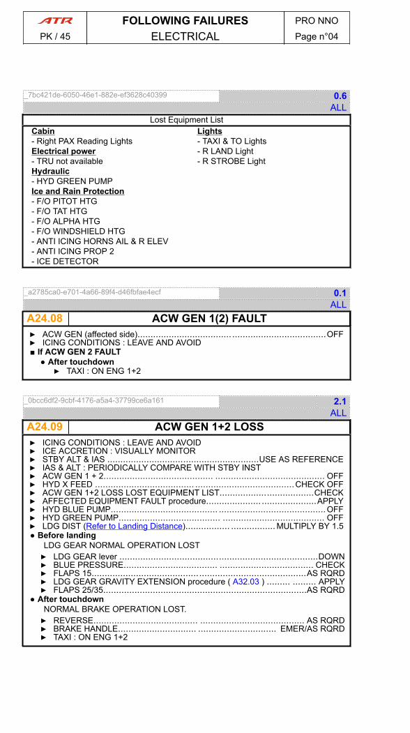
_7bc421de-6050-46e1-882e-ef3628c40399 0.6ALL
Lost Equipment ListCabin- Right PAX Reading LightsElectrical power- TRU not availableHydraulic- HYD GREEN PUMPIce and Rain Protection- F/O PITOT HTG- F/O TAT HTG- F/O ALPHA HTG- F/O WINDSHIELD HTG- ANTI ICING HORNS AIL & R ELEV- ANTI ICING PROP 2- ICE DETECTOR
Lights- TAXI & TO Lights- R LAND Light- R STROBE Light
_a2785ca0-e701-4a66-89f4-d46fbfae4ecf 0.1ALL
A24.08 ACW GEN 1(2) FAULT▶ ACW GEN (affected side)........................................................................OFF▶ ICING CONDITIONS : LEAVE AND AVOID■ If ACW GEN 2 FAULT
● After touchdown▶ TAXI : ON ENG 1+2
_0bcc6df2-9cbf-4176-a5a4-37799ce6a161 2.1ALL
A24.09 ACW GEN 1+2 LOSS▶ ICING CONDITIONS : LEAVE AND AVOID▶ ICE ACCRETION : VISUALLY MONITOR▶ STBY ALT & IAS ..........................................................USE AS REFERENCE▶ IAS & ALT : PERIODICALLY COMPARE WITH STBY INST▶ ACW GEN 1 + 2.......................................... .......................................... OFF▶ HYD X FEED ...................................... ......................................CHECK OFF▶ ACW GEN 1+2 LOSS LOST EQUIPMENT LIST....................................CHECK▶ AFFECTED EQUIPMENT FAULT procedure..................... .....................APPLY▶ HYD BLUE PUMP......................................... .........................................OFF▶ HYD GREEN PUMP....................................... ....................................... OFF▶ LDG DIST (Refer to Landing Distance)................. ................. MULTIPLY BY 1.5● Before landing
LDG GEAR NORMAL OPERATION LOST▶ LDG GEAR lever ............................................................................DOWN▶ BLUE PRESSURE.................................... .................................... CHECK▶ FLAPS 15..................................................................................AS RQRD▶ LDG GEAR GRAVITY EXTENSION procedure ( A32.03 ) ......... ......... APPLY▶ FLAPS 25/35..............................................................................AS RQRD
● After touchdownNORMAL BRAKE OPERATION LOST.▶ REVERSE........................................ ........................................ AS RQRD▶ BRAKE HANDLE.............................. .............................. EMER/AS RQRD▶ TAXI : ON ENG 1+2
FOLLOWING FAILURES PRO NNO
PK / 45 ELECTRICAL Page n°04
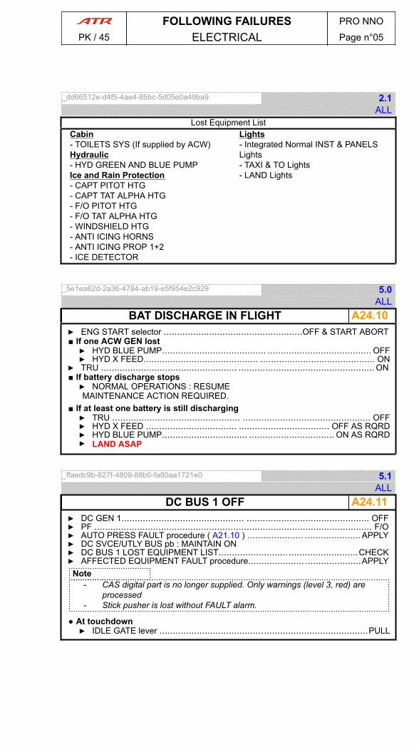
_dd66512e-d4f5-4ae4-85bc-5d05e0a49ba9 2.1ALL
Lost Equipment ListCabin- TOILETS SYS (If supplied by ACW)Hydraulic- HYD GREEN AND BLUE PUMPIce and Rain Protection- CAPT PITOT HTG- CAPT TAT ALPHA HTG- F/O PITOT HTG- F/O TAT ALPHA HTG- WINDSHIELD HTG- ANTI ICING HORNS- ANTI ICING PROP 1+2- ICE DETECTOR
Lights- Integrated Normal INST & PANELSLights- TAXI & TO Lights- LAND Lights
_5e1ea62d-2a36-4784-ab19-e5f954e2c929 5.0ALL
A24.10BAT DISCHARGE IN FLIGHT▶ ENG START selector ....................................................OFF & START ABORT■ If one ACW GEN lost▶ HYD BLUE PUMP....................................... ....................................... OFF▶ HYD X FEED........................................... ........................................... ON
▶ TRU ................................................... ................................................... ON■ If battery discharge stops▶ NORMAL OPERATIONS : RESUMEMAINTENANCE ACTION REQUIRED.
■ If at least one battery is still discharging▶ TRU ................................................ ................................................ OFF▶ HYD X FEED .................................. .................................. OFF AS RQRD▶ HYD BLUE PUMP................................ ................................ ON AS RQRD▶ LAND ASAP
_ffaedc9b-827f-4809-88b0-fa80aa1721e0 5.1ALL
A24.11DC BUS 1 OFF▶ DC GEN 1.............................................. .............................................. OFF▶ PF ........................................................................................................ F/O▶ AUTO PRESS FAULT procedure ( A21.10 ) ..................... ..................... APPLY▶ DC SVCE/UTLY BUS pb : MAINTAIN ON▶ DC BUS 1 LOST EQUIPMENT LIST.......................... ..........................CHECK▶ AFFECTED EQUIPMENT FAULT procedure..................... .....................APPLY
Note- CAS digital part is no longer supplied. Only warnings (level 3, red) are
processed- Stick pusher is lost without FAULT alarm.
● At touchdown▶ IDLE GATE lever ..............................................................................PULL
FOLLOWING FAILURES PRO NNO
PK / 45 ELECTRICAL Page n°05
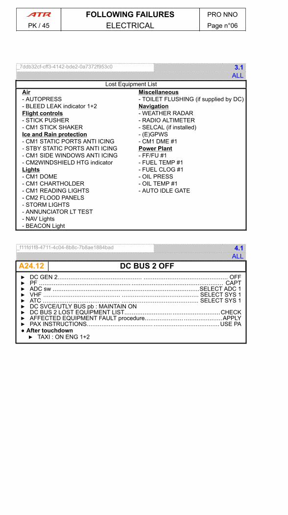
_7ddb32cf-cff3-4142-bde2-0a7372f953c0 3.1ALL
Lost Equipment ListAir- AUTOPRESS- BLEED LEAK indicator 1+2Flight controls- STICK PUSHER- CM1 STICK SHAKERIce and Rain protection- CM1 STATIC PORTS ANTI ICING- STBY STATIC PORTS ANTI ICING- CM1 SIDE WINDOWS ANTI ICING- CM2WINDSHIELD HTG indicatorLights- CM1 DOME- CM1 CHARTHOLDER- CM1 READING LIGHTS- CM2 FLOOD PANELS- STORM LIGHTS- ANNUNCIATOR LT TEST- NAV Lights- BEACON Light
Miscellaneous- TOILET FLUSHING (if supplied by DC)Navigation- WEATHER RADAR- RADIO ALTIMETER- SELCAL (if installed)- (E)GPWS- CM1 DME #1Power Plant- FF/FU #1- FUEL TEMP #1- FUEL CLOG #1- OIL PRESS- OIL TEMP #1- AUTO IDLE GATE
_f11fd1f8-4711-4c04-8b8c-7b8ae1884bad 4.1ALL
A24.12 DC BUS 2 OFF▶ DC GEN 2.............................................. .............................................. OFF▶ PF .................................................. .................................................. CAPT▶ ADC sw ................................................................................SELECT ADC 1▶ VHF .......................................... .......................................... SELECT SYS 1▶ ATC .......................................... .......................................... SELECT SYS 1▶ DC SVCE/UTLY BUS pb : MAINTAIN ON▶ DC BUS 2 LOST EQUIPMENT LIST.......................... ..........................CHECK▶ AFFECTED EQUIPMENT FAULT procedure..................... .....................APPLY▶ PAX INSTRUCTIONS.................................... ....................................USE PA● After touchdown▶ TAXI : ON ENG 1+2
FOLLOWING FAILURES PRO NNO
PK / 45 ELECTRICAL Page n°06
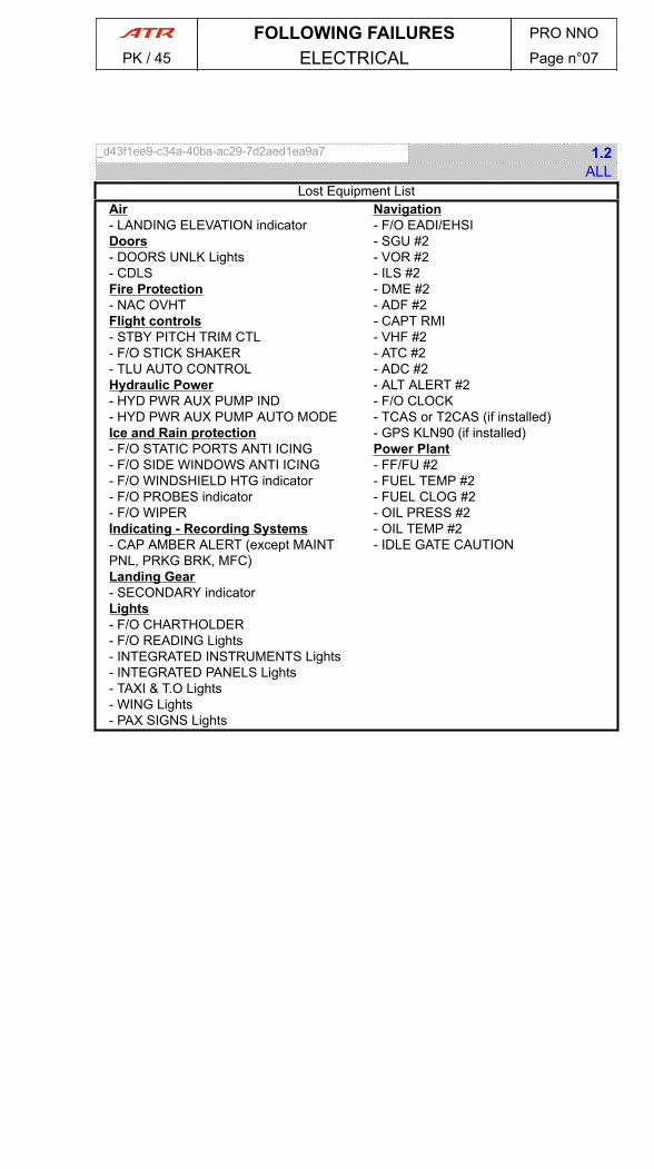
_d43f1ee9-c34a-40ba-ac29-7d2aed1ea9a7 1.2ALL
Lost Equipment ListAir- LANDING ELEVATION indicatorDoors- DOORS UNLK Lights- CDLSFire Protection- NAC OVHTFlight controls- STBY PITCH TRIM CTL- F/O STICK SHAKER- TLU AUTO CONTROLHydraulic Power- HYD PWR AUX PUMP IND- HYD PWR AUX PUMP AUTO MODEIce and Rain protection- F/O STATIC PORTS ANTI ICING- F/O SIDE WINDOWS ANTI ICING- F/O WINDSHIELD HTG indicator- F/O PROBES indicator- F/O WIPERIndicating - Recording Systems- CAP AMBER ALERT (except MAINTPNL, PRKG BRK, MFC)Landing Gear- SECONDARY indicatorLights- F/O CHARTHOLDER- F/O READING Lights- INTEGRATED INSTRUMENTS Lights- INTEGRATED PANELS Lights- TAXI & T.O Lights- WING Lights- PAX SIGNS Lights
Navigation- F/O EADI/EHSI- SGU #2- VOR #2- ILS #2- DME #2- ADF #2- CAPT RMI- VHF #2- ATC #2- ADC #2- ALT ALERT #2- F/O CLOCK- TCAS or T2CAS (if installed)- GPS KLN90 (if installed)Power Plant- FF/FU #2- FUEL TEMP #2- FUEL CLOG #2- OIL PRESS #2- OIL TEMP #2- IDLE GATE CAUTION
FOLLOWING FAILURES PRO NNO
PK / 45 ELECTRICAL Page n°07
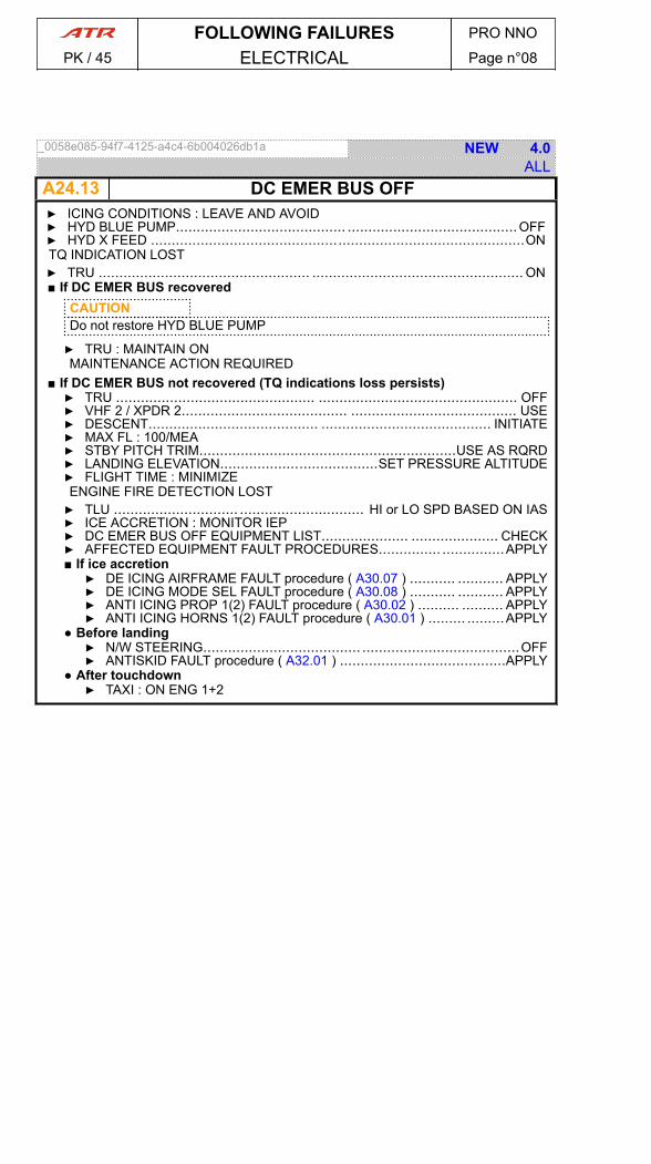
_0058e085-94f7-4125-a4c4-6b004026db1a NEW 4.0ALL
A24.13 DC EMER BUS OFF▶ ICING CONDITIONS : LEAVE AND AVOID▶ HYD BLUE PUMP......................................... .........................................OFF▶ HYD X FEED ..........................................................................................ONTQ INDICATION LOST▶ TRU ................................................... ................................................... ON■ If DC EMER BUS recovered
CAUTIONDo not restore HYD BLUE PUMP
▶ TRU : MAINTAIN ONMAINTENANCE ACTION REQUIRED
■ If DC EMER BUS not recovered (TQ indications loss persists)▶ TRU ................................................ ................................................ OFF▶ VHF 2 / XPDR 2........................................ ........................................ USE▶ DESCENT......................................... ......................................... INITIATE▶ MAX FL : 100/MEA▶ STBY PITCH TRIM..............................................................USE AS RQRD▶ LANDING ELEVATION......................................SET PRESSURE ALTITUDE▶ FLIGHT TIME : MINIMIZEENGINE FIRE DETECTION LOST▶ TLU .............................. .............................. HI or LO SPD BASED ON IAS▶ ICE ACCRETION : MONITOR IEP▶ DC EMER BUS OFF EQUIPMENT LIST..................... ..................... CHECK▶ AFFECTED EQUIPMENT FAULT PROCEDURES............... ...............APPLY■ If ice accretion▶ DE ICING AIRFRAME FAULT procedure ( A30.07 ) ........... ........... APPLY▶ DE ICING MODE SEL FAULT procedure ( A30.08 ) ........... ........... APPLY▶ ANTI ICING PROP 1(2) FAULT procedure ( A30.02 ) .......... .......... APPLY▶ ANTI ICING HORNS 1(2) FAULT procedure ( A30.01 ) ......... .........APPLY
● Before landing▶ N/W STEERING...................................... ......................................OFF▶ ANTISKID FAULT procedure ( A32.01 ) ........................................APPLY
● After touchdown▶ TAXI : ON ENG 1+2
FOLLOWING FAILURES PRO NNO
PK / 45 ELECTRICAL Page n°08
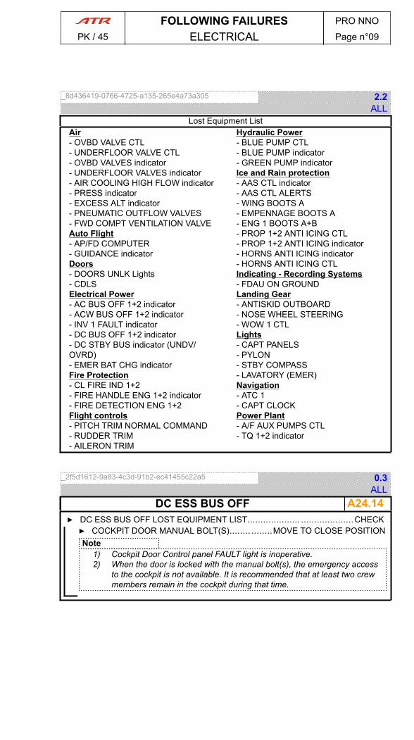
_8d436419-0766-4725-a135-265e4a73a305 2.2ALL
Lost Equipment ListAir- OVBD VALVE CTL- UNDERFLOOR VALVE CTL- OVBD VALVES indicator- UNDERFLOOR VALVES indicator- AIR COOLING HIGH FLOW indicator- PRESS indicator- EXCESS ALT indicator- PNEUMATIC OUTFLOW VALVES- FWD COMPT VENTILATION VALVEAuto Flight- AP/FD COMPUTER- GUIDANCE indicatorDoors- DOORS UNLK Lights- CDLSElectrical Power- AC BUS OFF 1+2 indicator- ACW BUS OFF 1+2 indicator- INV 1 FAULT indicator- DC BUS OFF 1+2 indicator- DC STBY BUS indicator (UNDV/OVRD)- EMER BAT CHG indicatorFire Protection- CL FIRE IND 1+2- FIRE HANDLE ENG 1+2 indicator- FIRE DETECTION ENG 1+2Flight controls- PITCH TRIM NORMAL COMMAND- RUDDER TRIM- AILERON TRIM
Hydraulic Power- BLUE PUMP CTL- BLUE PUMP indicator- GREEN PUMP indicatorIce and Rain protection- AAS CTL indicator- AAS CTL ALERTS- WING BOOTS A- EMPENNAGE BOOTS A- ENG 1 BOOTS A+B- PROP 1+2 ANTI ICING CTL- PROP 1+2 ANTI ICING indicator- HORNS ANTI ICING indicator- HORNS ANTI ICING CTLIndicating - Recording Systems- FDAU ON GROUNDLanding Gear- ANTISKID OUTBOARD- NOSE WHEEL STEERING- WOW 1 CTLLights- CAPT PANELS- PYLON- STBY COMPASS- LAVATORY (EMER)Navigation- ATC 1- CAPT CLOCKPower Plant- A/F AUX PUMPS CTL- TQ 1+2 indicator
_2f5d1612-9a83-4c3d-91b2-ec41455c22a5 0.3ALL
A24.14DC ESS BUS OFF▶ DC ESS BUS OFF LOST EQUIPMENT LIST.................... ....................CHECK▶ COCKPIT DOOR MANUAL BOLT(S)........ ........MOVE TO CLOSE POSITIONNote
1) Cockpit Door Control panel FAULT light is inoperative.2) When the door is locked with the manual bolt(s), the emergency access
to the cockpit is not available. It is recommended that at least two crewmembers remain in the cockpit during that time.
FOLLOWING FAILURES PRO NNO
PK / 45 ELECTRICAL Page n°09

_22c4d4d5-031c-4156-b4b2-595114aa5099 2.2ALL
Lost Equipment List - Part 1Air- PACK VALVE 1+2- RECIRC FAN 1+2 indicator- EXTRACT FAN CTL- LANDING ELEVATION indicator- COCKPIT AUTOMATIC TEMP CTL- COCKPIT MANUAL TEMP CTL- CABIN AUTOMATIC TEMP CTL- CABIN MANUAL TEMP CTL- COCKPIT TEMP indicator- CABIN TEMP indicatorAuto Flight- AP OFF indicator- DISC by QUICK DISCONNECTCommunication- FLIGHT INTERPHONES- AUDIO CONTROL PANELS- CAPT COCKPIT AMPLIFIER- CVR / PASSENGER ADDRESS- MECHANICAL CALL- COCKPIT CREW CALL- CABIN CREW CALLElectrical Power- DC SVCE BUS 1+2 CTL- DC UTLY BUS 1+2 CTL- MAIN BAT CHG indicator- INV 2 FAULT indicator
Fire Protection- AVIONICS SMK DET- TOILETS SMK DET- FWD COMPT SMK DET- AFT COMPT SMK DET- AFT COMPT CTL- AFT COMPT indicator- FWD COMPT CTL- FWD COMPT indicator- Toilets DET FANS CTL- Toilets DET FANS indicator-FWD COMPT Fire Extinguishing CTLindicator- FWD COMPT Fire Extinguishing CTLTEST- AUX AFT COMPTFlight controls- CLUTCH REENGAGEMENT SYSTEM- AILERON LOCKING CTLFuel- FQI 1+2- X FEED VALVE- STARTING PUMPS 1+2- MOTIVE FLOW VALVES 1+2Hydraulic Power- GREEN PUMP CTL
_9c5ae291-98bb-4b8a-ba18-e5c53a766690 1.1ALL
Lost Equipment List - Part 2Ice and Rain protection- DE ICING ISOL VALVES-SIDE WINDOWS ANTI ICING indicator- CAPT PROBES indicator- STBY PROBES indicator- TAT PROBES indicator- CAPT WIPERIndicating - Recording Systems- FDAU in FLIGHTLanding Gear- ANTISKID OUTBOARD- NOSE WHEEL STEERINGNavigation- TAS TEMP indicator
Oxygen- PRESS indicator- FLIGHT CREW VALVES CTL- PAX VALVES CTL- PAX MASKS DROP CTLPower Plant- IGNITION 1+2- STARTING 1+2- NH 1+2 indicator- ITT 1+2 indicator- PROP BRK PWR CTL- PROP BRK PWR indicator
FOLLOWING FAILURES PRO NNO
PK / 45 ELECTRICAL Page n°10
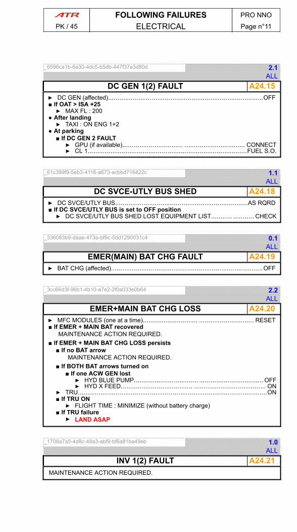
_6596ca1b-6a30-4dc5-b5db-447f37e3d80d 2.1ALL
A24.15DC GEN 1(2) FAULT▶ DC GEN (affected)..................................................................................OFF■ If OAT > ISA +25▶ MAX FL : 200
● After landing▶ TAXI : ON ENG 1+2
● At parking■ If DC GEN 2 FAULT▶ GPU (if available)................................ ................................ CONNECT▶ CL 1....................................................................................FUEL S.O.
_61c399f9-5eb3-4116-a673-acbbd716422c 1.1ALL
A24.18DC SVCE-UTLY BUS SHED▶ DC SVCE/UTLY BUS......................................................................AS RQRD■ If DC SVCE/UTLY BUS is set to OFF position▶ DC SVCE/UTLY BUS SHED LOST EQUIPMENT LIST........... ........... CHECK
_336083b9-daae-473e-bf9c-5dd1290031c4 0.1ALL
A24.19EMER(MAIN) BAT CHG FAULT▶ BAT CHG (affected)........................................ ........................................OFF
_3cc66d3f-96b1-4b10-a7e2-2f0a033e0b64 2.2ALL
A24.20EMER+MAIN BAT CHG LOSS▶ MFC MODULES (one at a time)............................. ............................. RESET■ If EMER + MAIN BAT recovered
MAINTENANCE ACTION REQUIRED.■ If EMER + MAIN BAT CHG LOSS persists
■ If no BAT arrowMAINTENANCE ACTION REQUIRED.
■ If BOTH BAT arrows turned on■ If one ACW GEN lost▶ HYD BLUE PUMP.................................. .................................. OFF▶ HYD X FEED...................................... ...................................... ON
▶ TRU....................................................................................................ON■ If TRU ON▶ FLIGHT TIME : MINIMIZE (without battery charge)
■ If TRU failure▶ LAND ASAP
_1708a7a5-4d8c-48a3-abf9-bf6a81ba49eb 1.0ALL
A24.21INV 1(2) FAULTMAINTENANCE ACTION REQUIRED.
FOLLOWING FAILURES PRO NNO
PK / 45 ELECTRICAL Page n°11
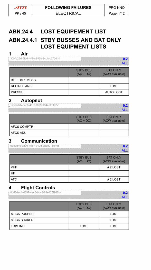
ABN.24.4 LOST EQUIPEMENT LISTABN.24.4.1 STBY BUSSES AND BAT ONLY
LOST EQUIPMENT LISTS1 Air_30bfe26d-9fb6-408e-853b-8cbfec270d1d 0.2
ALL
STBY BUS(AC + DC)
BAT ONLY(ACW available)
BLEEDS / PACKS
RECIRC FANS LOST
PRESSU AUTO LOST
2 Autopilot_1efdad2b-bac8-40cf-9699-194e22df9f5b 0.2
ALL
STBY BUS(AC + DC)
BAT ONLY(ACW available)
AFCS COMPTR
AFCS ADU
3 Communication_6effad46-da00-4967-b40d-ea3ff9155465 0.2
ALL
STBY BUS(AC + DC)
BAT ONLY(ACW available)
VHF # 2 LOST
HF
ATC # 2 LOST
4 Flight Controls_0b68dec1-d397-4ec6-bb43-89e425f968b4 0.2
ALL
STBY BUS(AC + DC)
BAT ONLY(ACW available)
STICK PUSHER LOST
STICK SHAKER LOST
TRIM IND LOST LOST
FOLLOWING FAILURES PRO NNO
PK / 45 ELECTRICAL Page n°12

5 Hydraulic_65a8eaca-ee36-4ffd-a071-a2b3b0e47812 0.2
ALL
STBY BUS(AC + DC)
BAT ONLY(ACW available)
MAIN PUMPS
AUX PUMP LOST
PRESS IND LOST
FLAPS LOST
X FEED VALVE LOST
6 Indicating and Recording Systems_d09b758a-a6f9-40fc-9d6d-8a53345145c7 0.2
ALL
STBY BUS(AC + DC)
BAT ONLY(ACW available)
CCAS AMBER ALERTSLOST
7 Landing Gear_2cc1198a-44e4-423e-8b13-5f2008c2cb85 0.2
ALL
STBY BUS(AC + DC)
BAT ONLY(ACW available)
L/G RET LOST
L/G EXT EMER ONLY
L/G POS IND MAIN panel LOST OVHD panel LOST
ANTISKID
8 Lights_fdcca3dc-a9ad-4b2f-9a3b-f852cac30e3c 0.2
ALL
STBY BUS(AC + DC)
BAT ONLY(ACW available)
TAXI AND T.O. Lights LOST
FOLLOWING FAILURES PRO NNO
PK / 45 ELECTRICAL Page n°13
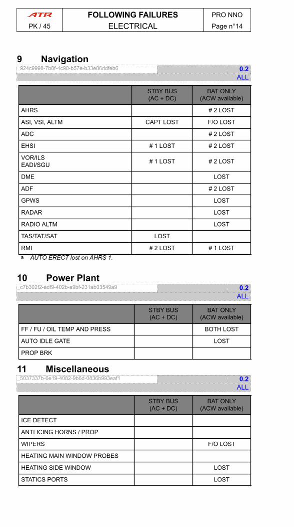
9 Navigation_924c9998-7b8f-4c90-b57e-b33e86ddfeb6 0.2
ALL
STBY BUS(AC + DC)
BAT ONLY(ACW available)
AHRS # 2 LOST
ASI, VSI, ALTM CAPT LOST F/O LOST
ADC # 2 LOST
EHSI # 1 LOST # 2 LOST
VOR/ILSEADI/SGU # 1 LOST # 2 LOST
DME LOST
ADF # 2 LOST
GPWS LOST
RADAR LOST
RADIO ALTM LOST
TAS/TAT/SAT LOST
RMI # 2 LOST # 1 LOSTa AUTO ERECT lost on AHRS 1.
10 Power Plant_c7b302f2-adf9-402b-a9bf-231ab03549a9 0.2
ALL
STBY BUS(AC + DC)
BAT ONLY(ACW available)
FF / FU / OIL TEMP AND PRESS BOTH LOST
AUTO IDLE GATE LOST
PROP BRK
11 Miscellaneous_5037337b-6e19-4082-9b6d-0836b993eaf1 0.2
ALL
STBY BUS(AC + DC)
BAT ONLY(ACW available)
ICE DETECT
ANTI ICING HORNS / PROP
WIPERS F/O LOST
HEATING MAIN WINDOW PROBES
HEATING SIDE WINDOW LOST
STATICS PORTS LOST
FOLLOWING FAILURES PRO NNO
PK / 45 ELECTRICAL Page n°14

_fb241c40-75aa-450f-85f8-47947913854e 2.1ALL
A27.01FLAPS ASYM▶ FLAPS CONTROL lever ............. ............. NEAR FLAPS PRESENT POSITION● For approach▶ REDUCED FLAPS LANDING procedure ( A27.05 ) ............................APPLY
_25574cb0-5e59-4522-a5d2-53f17342260c 2.1ALL
A27.02FLAPS JAM▶ FLAPS CONTROL lever ............. ............. NEAR FLAPS PRESENT POSITION● For approach▶ REDUCED FLAPS LANDING procedure ( A27.05 ) ............................APPLY
_d83c9f41-5062-4b93-935f-2a547ddfa279 3.1ALL
A27.04FLAPS UNLK● Before V1▶ TAKEOFF.......................................... .......................................... ABORT
● After V1▶ VR, V2 ................................... ................................... INCREASE BY 10 kt
● If alarm occurs during approach▶ GO-AROUND..................................... ..................................... PERFORM▶ VGA ..........................................................................INCREASE BY 10 kt
● When possible▶ FLAPS................................................. ................................................. 0
● For approach▶ REDUCED FLAPS LANDING procedure ( A27.05 ) ............................APPLY
FOLLOWING FAILURES PRO NNO
PK / 45 FLIGHT CONTROLS Page n°01
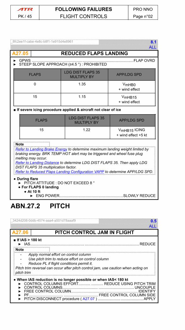
_8fc2ee1f-cabe-4e8c-b8f1-1e915d4e8961 8.1ALL
A27.05 REDUCED FLAPS LANDING▶ GPWS ......................................................................................FLAP OVRD▶ STEEP SLOPE APPROACH (≥4.5 °) : PROHIBITED
FLAPS LDG DIST FLAPS 35MULTIPLY BY APP/LDG SPD
0 1.35 VmHB0+ wind effect
15 1.15 VmHB15+ wind effect
■ If severe icing procedure applied & aircraft not clear of ice
FLAPS LDG DIST FLAPS 35MULTIPLY BY APP/LDG SPD
15 1.22 VmHB15 ICING+ wind effect +5 kt
NoteRefer to Landing Brake Energy to determine maximum landing weight limited bybraking energy. BRK TEMP HOT alert may be triggered and wheel fuse plugmelting may occur.Refer to Landing Distance to determine LDG DIST FLAPS 35. Then apply LDGDIST FLAPS 35 multiplication factor.Refer to Reduced Flaps Landing Configuration VAPP to determine APP/LDG SPD.
● During flare▶ PITCH ATTITUDE : DO NOT EXCEED 8 °● For FLAPS 0 landing
● At 10 ft▶ ENG POWER......................................................SLOWLY REDUCE
ABN.27.2 PITCH
_3424d208-0ddb-4574-aaa4-a501d78aaaf9 0.5ALL
A27.06 PITCH CONTROL JAM IN FLIGHT■ If IAS > 180 kt▶ IAS.............................................. .............................................. REDUCE
Note- Apply normal effort on control column- Use pitch trim to reduce effort on control column- Reduce PL if flight conditions permit it.
Pitch trim reversal can occur after pitch control jam, use caution when acting onpitch trim
● When IAS reduction is no longer possible or when IAS< 180 kt▶ CONTROL COLUMNS EFFORT.......... .......... REDUCE USING PITCH TRIM▶ CONTROL COLUMNS.............................. .............................. UNCOUPLE▶ FREE CONTROL COLUMN............................ ............................ IDENTIFY▶ PF............................. ............................. FREE CONTROL COLUMN SIDE▶ PITCH DISCONNECT procedure ( A27.07 ) ................... ...................APPLY
FOLLOWING FAILURES PRO NNO
PK / 45 FLIGHT CONTROLS Page n°02
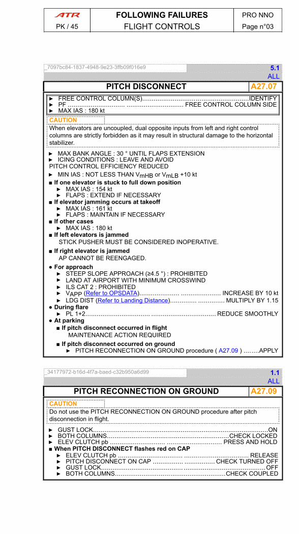
_7097bc84-1837-4948-9e23-3ffb09f016e9 5.1ALL
A27.07PITCH DISCONNECT▶ FREE CONTROL COLUMN(S)........................................................IDENTIFY▶ PF .............................. .............................. FREE CONTROL COLUMN SIDE▶ MAX IAS : 180 ktCAUTIONWhen elevators are uncoupled, dual opposite inputs from left and right controlcolumns are strictly forbidden as it may result in structural damage to the horizontalstabilizer.
▶ MAX BANK ANGLE : 30 ° UNTIL FLAPS EXTENSION▶ ICING CONDITIONS : LEAVE AND AVOIDPITCH CONTROL EFFICIENCY REDUCED▶ MIN IAS : NOT LESS THAN VmHB or VmLB +10 kt■ If one elevator is stuck to full down position▶ MAX IAS : 154 kt▶ FLAPS : EXTEND IF NECESSARY
■ If elevator jamming occurs at takeoff▶ MAX IAS : 161 kt▶ FLAPS : MAINTAIN IF NECESSARY
■ If other cases▶ MAX IAS : 180 kt
■ If left elevators is jammedSTICK PUSHER MUST BE CONSIDERED INOPERATIVE.
■ If right elevator is jammedAP CANNOT BE REENGAGED.
● For approach▶ STEEP SLOPE APPROACH (≥4.5 °) : PROHIBITED▶ LAND AT AIRPORT WITH MINIMUM CROSSWIND▶ ILS CAT 2 : PROHIBITED▶ VAPP (Refer to OPSDATA)..................... ..................... INCREASE BY 10 kt▶ LDG DIST (Refer to Landing Distance).............. .............. MULTIPLY BY 1.15
● During flare▶ PL 1+2.................................. .................................. REDUCE SMOOTHLY
● At parking■ If pitch disconnect occurred in flight
MAINTENANCE ACTION REQUIRED■ If pitch disconnect occurred on ground▶ PITCH RECONNECTION ON GROUND procedure ( A27.09 ) ........APPLY
_34177972-b16d-4f7a-baed-c32b950a6d99 1.1ALL
A27.09PITCH RECONNECTION ON GROUNDCAUTIONDo not use the PITCH RECONNECTION ON GROUND procedure after pitchdisconnection in flight.
▶ GUST LOCK............................................................................................ON▶ BOTH COLUMNS................................................................CHECK LOCKED▶ ELEV CLUTCH pb ............................. ............................. PRESS AND HOLD■ When PITCH DISCONNECT flashes red on CAP▶ ELEV CLUTCH pb .................................. .................................. RELEASE▶ PITCH DISCONNECT ON CAP ................ ................ CHECK TURNED OFF▶ GUST LOCK........................................... ...........................................OFF▶ BOTH COLUMNS..........................................................CHECK COUPLED
FOLLOWING FAILURES PRO NNO
PK / 45 FLIGHT CONTROLS Page n°03
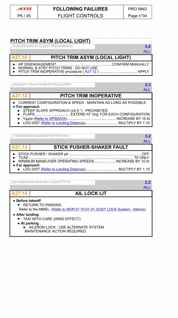
PITCH TRIM ASYM (LOCAL LIGHT)_b77f6a26-ba63-41c2-8237-9891e9a6d43d 3.0
ALL A27.10 PITCH TRIM ASYM (LOCAL LIGHT)▶ AP DISENGAGEMENT........................ ........................ CONFIRM MANUALLY▶ NORMAL & STBY PITCH TRIMS : DO NOT USE▶ PITCH TRIM INOPERATIVE procedure ( A27.12 ) ................ ................ APPLY
_2dfaad04-1c6a-4c14-b8c6-f12ccd1e264d 2.3ALL
A27.12 PITCH TRIM INOPERATIVE▶ CURRENT CONFIGURATION & SPEED : MAINTAIN AS LONG AS POSSIBLE● For approach▶ STEEP SLOPE APPROACH (≥4.5 °) : PROHIBITED▶ FLAPS............... ............... EXTEND AT VFE FOR EACH CONFIGURATION▶ VAPP (Refer to OPSDATA)..................... ..................... INCREASE BY 10 kt▶ LDG DIST (Refer to Landing Distance).............. .............. MULTIPLY BY 1.15
_3133eb8f-2084-43ef-960f-9cf7df74c5ae 3.2ALL
A27.13 STICK PUSHER-SHAKER FAULT▶ STICK PUSHER / SHAKER pb ................................................................OFF▶ TCAS ............................................. ............................................. TA ONLY▶ MINIMUM MANEUVER OPERATING SPEEDS......... ......... INCREASE BY 10 kt● For approach▶ LDG DIST (Refer to Landing Distance).............. .............. MULTIPLY BY 1.15
_bdcc48af-6ed8-4d08-afce-13cac417f178 2.2ALL
A27.14 AIL LOCK LIT● Before takeoff▶ RETURN TO PARKINGRefer to the MMEL. (Refer to MOP.27.70-01-01 GUST LOCK System - Aileron).
● After landing▶ TAXI WITH CARE (WIND EFFECT)● At parking▶ AILERON LOCK : USE ALTERNATE SYSTEMMAINTENANCE ACTION REQUIRED.
FOLLOWING FAILURES PRO NNO
PK / 45 FLIGHT CONTROLS Page n°04
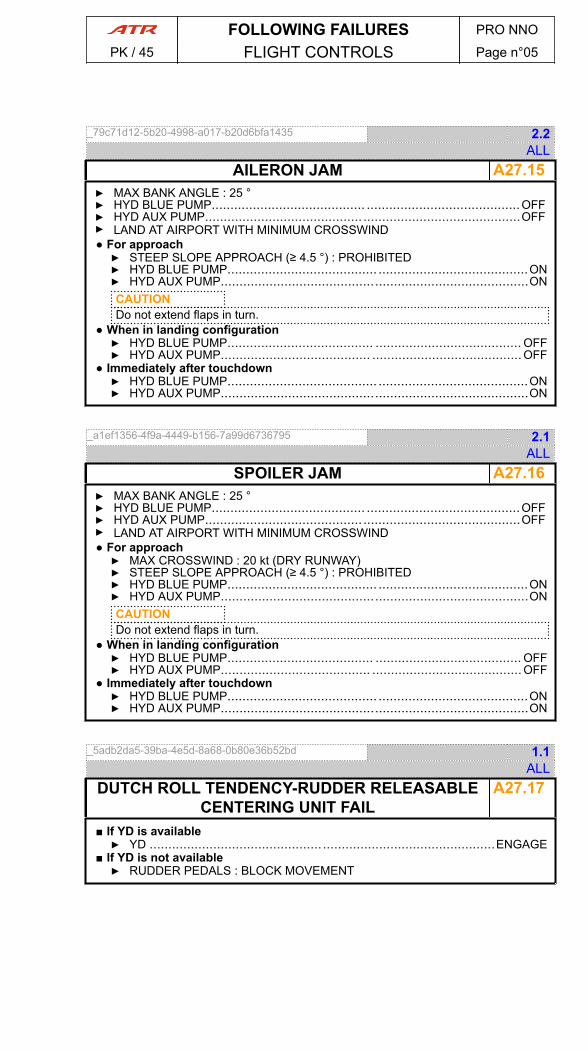
_79c71d12-5b20-4998-a017-b20d6bfa1435 2.2ALL
A27.15AILERON JAM▶ MAX BANK ANGLE : 25 °▶ HYD BLUE PUMP......................................... .........................................OFF▶ HYD AUX PUMP.......................................... ..........................................OFF▶ LAND AT AIRPORT WITH MINIMUM CROSSWIND● For approach▶ STEEP SLOPE APPROACH (≥ 4.5 °) : PROHIBITED▶ HYD BLUE PUMP........................................ ........................................ON▶ HYD AUX PUMP..................................................................................ONCAUTIONDo not extend flaps in turn.
● When in landing configuration▶ HYD BLUE PUMP....................................... ....................................... OFF▶ HYD AUX PUMP........................................ ........................................OFF
● Immediately after touchdown▶ HYD BLUE PUMP........................................ ........................................ON▶ HYD AUX PUMP..................................................................................ON
_a1ef1356-4f9a-4449-b156-7a99d6736795 2.1ALL
A27.16SPOILER JAM▶ MAX BANK ANGLE : 25 °▶ HYD BLUE PUMP......................................... .........................................OFF▶ HYD AUX PUMP.......................................... ..........................................OFF▶ LAND AT AIRPORT WITH MINIMUM CROSSWIND● For approach▶ MAX CROSSWIND : 20 kt (DRY RUNWAY)▶ STEEP SLOPE APPROACH (≥ 4.5 °) : PROHIBITED▶ HYD BLUE PUMP........................................ ........................................ON▶ HYD AUX PUMP..................................................................................ONCAUTIONDo not extend flaps in turn.
● When in landing configuration▶ HYD BLUE PUMP....................................... ....................................... OFF▶ HYD AUX PUMP........................................ ........................................OFF
● Immediately after touchdown▶ HYD BLUE PUMP........................................ ........................................ON▶ HYD AUX PUMP..................................................................................ON
_5adb2da5-39ba-4e5d-8a68-0b80e36b52bd 1.1ALL
A27.17DUTCH ROLL TENDENCY-RUDDER RELEASABLECENTERING UNIT FAIL
■ If YD is available▶ YD .............................................. ..............................................ENGAGE
■ If YD is not available▶ RUDDER PEDALS : BLOCK MOVEMENT
FOLLOWING FAILURES PRO NNO
PK / 45 FLIGHT CONTROLS Page n°05
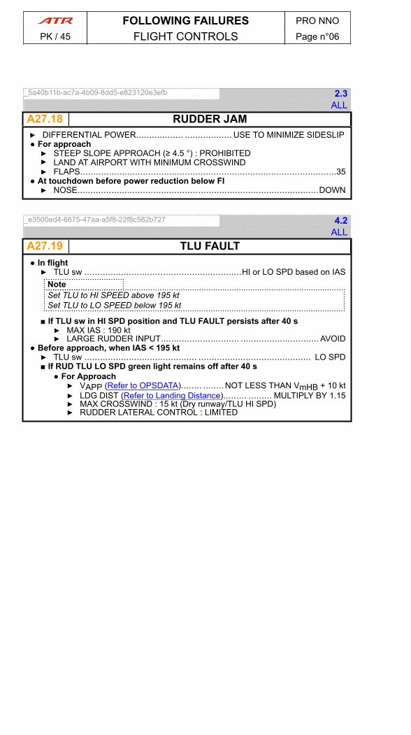
_5a40b11b-ac7a-4b09-8dd5-e823120e3efb 2.3ALL
A27.18 RUDDER JAM▶ DIFFERENTIAL POWER.................. .................. USE TO MINIMIZE SIDESLIP● For approach▶ STEEP SLOPE APPROACH (≥ 4.5 °) : PROHIBITED▶ LAND AT AIRPORT WITH MINIMUM CROSSWIND▶ FLAPS..................................................................................................35
● At touchdown before power reduction below FI▶ NOSE............................................................................................DOWN
_e3500ed4-6675-47aa-a5f8-22f8c582b727 4.2ALL
A27.19 TLU FAULT● In flight▶ TLU sw ............................................................HI or LO SPD based on IAS
NoteSet TLU to HI SPEED above 195 ktSet TLU to LO SPEED below 195 kt
■ If TLU sw in HI SPD position and TLU FAULT persists after 40 s▶ MAX IAS : 190 kt▶ LARGE RUDDER INPUT.............................. .............................. AVOID
● Before approach, when IAS < 195 kt▶ TLU sw ........................................... ........................................... LO SPD■ If RUD TLU LO SPD green light remains off after 40 s
● For Approach▶ VAPP (Refer to OPSDATA)........ ........NOT LESS THAN VmHB + 10 kt▶ LDG DIST (Refer to Landing Distance)......... ......... MULTIPLY BY 1.15▶ MAX CROSSWIND : 15 kt (Dry runway/TLU HI SPD)▶ RUDDER LATERAL CONTROL : LIMITED
FOLLOWING FAILURES PRO NNO
PK / 45 FLIGHT CONTROLS Page n°06

_d5badcac-cc58-4782-922d-d352789a45e0 0.2ALL
A28.01FUEL 1(2) ABNORMAL TEMP■ If FUEL TEMP > 50 °C▶ LARGE RAPID POWER CHANGE : AVOID▶ OIL TEMP : MONITOR▶ ENG PARAMETERS : MONITOR
■ If FUEL TEMP < 0 °CMAINTENANCE ACTION REQUIRED.NoteIf repair can not be done, use anti-ice additive for next refueling.
_2022f6a1-edb7-4257-88bf-dc9082c1eb4c 1.4ALL
A28.02FUEL CLOG■ If FUEL CLOG 1+2 lights come on:▶ ENG (1+2) PARAMETERS : MONITOR■ If abnormal engine parameters▶ LAND ASAP
MAINTENANCE ACTION REQUIREDNoteFuel contamination may be suspected.
■ If only FUEL CLOG 1(2) light comes on▶ ENG (affected) PARAMETERS : MONITOR
_22e3cbf6-0d71-4a29-8eac-96e138406950 3.1ALL
A28.03FUEL FEED LO PR▶ FUEL PUMP (affected side)........................... ........................... CONFIRM ON▶ ENG (affected) PARAMETERS : MONITOR■ If engine runs down- OR -
■ If fuel quantity decreases significantly▶ LAND ASAPCAUTIONX feed valve keep closed
▶ PL (affected ENG) ........................................ ........................................ FI▶ CL (affected ENG) ......................... ......................... FTR THEN FUEL S.O.▶ FUEL PUMP (affected side)................................ ................................ OFF▶ FIRE HANDLE (affected ENG)............................................................PULL▶ SINGLE ENG OPERATION procedure ( A70.12 ) ............... ............... APPLY
FOLLOWING FAILURES PRO NNO
PK / 45 FUEL Page n°01

_e4f1bcf6-a1c4-4f7c-b4f9-91d32d0ef846 1.0ALL
A28.04 FUEL LEAK DETECTIONA fuel leak may be detected by:
- Sum of fuel on board (FOB), read in steady flight at cruise level, and fuel used(FU), FOB+FU significantly less than fuel at departure
- Total fuel quantity decreasing at an abnormal rate- Fuel unbalance- Tank emptying too fast (leak from engine or a hole in a tank)- Excessive fuel flow (leak from engine)- Fuel smell in the cabin.- Fuel spray from engine or wing tip (leak from engine or hole in tank).
■ If fuel leak suspected:▶ FUEL LEAK procedure ( A28.05 ) .......................... .......................... APPLY
_2c399503-39ec-45a9-a888-d9f8c0d19764 4.0ALL
A28.05 FUEL LEAK■ If leak confirmed▶ LAND ASAP■ If leak from engine (excessive fuel flow or feed spray from engine)▶ PL (affected ENG) ..................................... ..................................... FI▶ CL (affected ENG) .............................................. FTR THEN FUEL S.O.▶ FUEL PUMP (affected side).............................. ..............................OFF▶ FIRE HANDLE (affected ENG)........................... ........................... PULL■ If excessive fuel flow was identified before engine shutdown
FUEL X FEED VALVE CAN BE OPENED.■ In all other cases▶ FUEL X FEED : KEEP CLOSED
▶ SINGLE ENG OPERATION procedure ( A70.12 ) ..........................APPLY■ If leak not located▶ FUEL X FEED : KEEP CLOSED
● Before landing▶ ATC ........................................... ........................................... NOTIFY
_c6f7333a-f729-411e-96f6-995230574496 5.1ALL
A28.06 FUEL LO LVL▶ EXCESSIVE AIRCRAFT ATTITUDES : AVOID■ If both LO LVL lights come on▶ LAND ASAP
■ If only one LO LVL light comes on■ If leak suspected▶ FUEL LEAK procedure ( A28.05 ) ................................................APPLY
■ If no leak suspected■ If Fuel Quantity Indication < 160 kg (352 lb)▶ FUEL X FEED ..................................... ..................................... ON
■ If Fuel Quantity Indication ≥ 160 kg (352 lb)▶ FUEL X FEED : KEEP CLOSED▶ FUEL COMSUMPTION : MONITOR▶ UNUSABLE FUEL IN AFFECTED TANK : 130 kg (287 lb)
FOLLOWING FAILURES PRO NNO
PK / 45 FUEL Page n°02

_e5187a5a-038d-4f45-8503-1a06d542c41d 2.2ALL
A28.08FUEL UNBALANCED■ If FUEL LEAK suspected▶ FUEL LEAK procedure ( A28.05 ) .......................... .......................... APPLY
■ If normal fuel condition■ If LEFT TANK QTY > RIGHT TANK QTY▶ FUEL X FEED .................................... .................................... IN LINE▶ FUEL PUMP LEFT............................... ...............................CHECK ON▶ FUEL PUMP RIGHT................................... ................................... OFF● When fuel balanced▶ FUEL PUMP RIGHT................................. ................................. ON▶ FUEL X FEED................................... ...................................X LINE
■ If LEFT TANK QTY < RIGHT TANK QTY▶ FUEL X FEED .................................... .................................... IN LINE▶ FUEL PUMP RIGHT............................................................CHECK ON▶ FUEL PUMP LEFT.................................... .................................... OFF● When fuel balanced▶ FUEL PUMP LEFT.................................. .................................. ON▶ FUEL X FEED................................... ...................................X LINE
FOLLOWING FAILURES PRO NNO
PK / 45 FUEL Page n°03
PAGE
INTENTIONALLY
LEFT BLANK
FOLLOWING FAILURES PRO NNO
PK / 45 FUEL Page n°04

_191238a6-7ad4-4456-835d-666ea6668cd8 5.1ALL
A29.01HYD BLUE (GREEN) LO LVL■ If blue hydraulic system affected▶ HYD X FEED..........................................................................CHECK OFF▶ HYD BLUE PUMP....................................... ....................................... OFF▶ HYD AUX PUMP........................................ ........................................OFF▶ HYD BLUE SYS LOST EQUIPMENT LIST........................................CHECK● For approach▶ REDUCED FLAPS LANDING procedure ( A27.05 ) ........... ........... APPLY
● At landingN/W STEERING LOST▶ DIFFERENTIAL BRAKING : USE▶ TAXI : ON ENG 1+2
■ If green hydraulic system affected▶ HYD X FEED..........................................................................CHECK OFF▶ HYD GREEN PUMP............................................................................OFF▶ LDG DIST (Refer to OPSDATA).................... .................... MULTIPLY BY 1.5▶ HYD GREEN SYS LOST EQUIPMENT LIST.................. .................. CHECK● Before landing
NORMAL BRAKING LOST▶ LDG GEAR GRAVITY EXTENSION procedure ( A32.03 ) ....... .......APPLY
● After touchdown▶ REVERSE...................................... ......................................AS RQRD▶ BRAKE HANDLE........................................................ EMER/AS RQRD▶ TAXI : ON ENG 1+2
_7d62bcad-a994-4250-b37d-b75af802d7e7 2.1ALL
HYD BLUE SYS LOST EQUIPMENT LISTFlight Controls- FLAPS- SPOILERS- N/W STEERINGPropellers- PROP BRAKE
Landing Gear- PARKING BRAKE- EMER BRAKE (accumulator allows atleast 6 applications of braking force atfull braking pressure)
_f06e248e-407b-43d8-8030-66ec4d37edf7 1.0ALL
HYD GREEN SYS LOST EQUIPMENT LISTLanding Gear- LDG GEAR EXTENSION
- LDG GEAR RETRACTION- NORMAL BRAKE
_098137bc-857a-40d8-a354-0913db80e84e 2.3ALL
A29.02HYD BLUE (GREEN) LO PR▶ HYD (affected) PUMP ...................................... ......................................OFF▶ HYD X FEED............................................. ............................................. ON▶ TAXI : ON ENG 1+2
FOLLOWING FAILURES PRO NNO
PK / 45 HYDRAULIC SYSTEM Page n°01
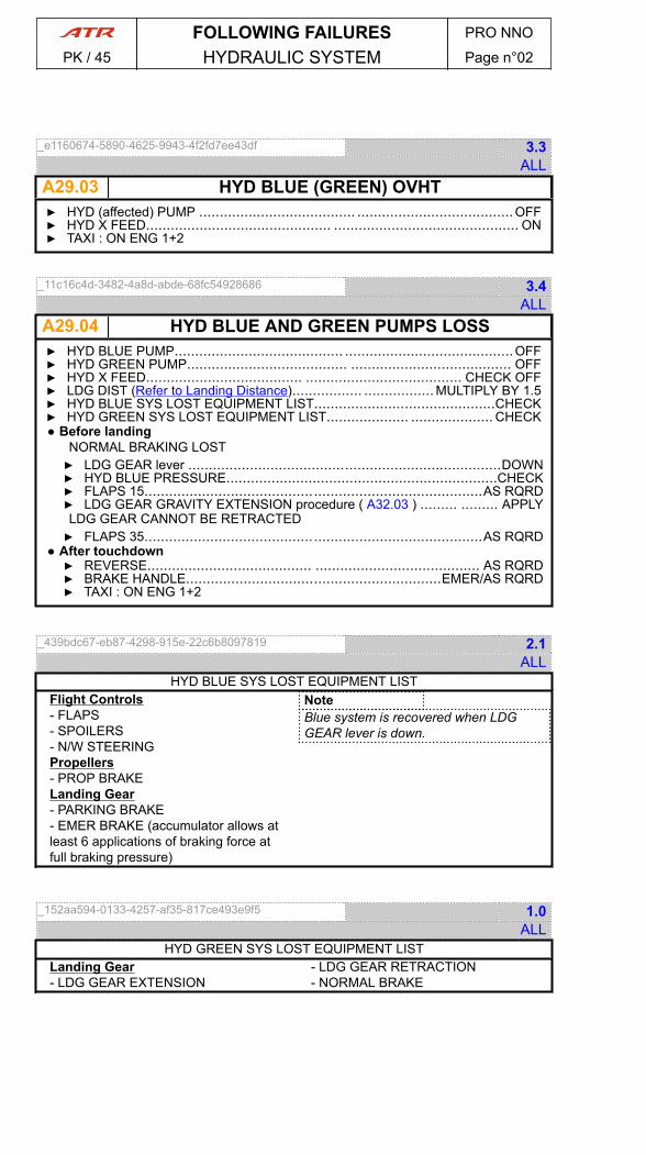
_e1160674-5890-4625-9943-4f2fd7ee43df 3.3ALL
A29.03 HYD BLUE (GREEN) OVHT▶ HYD (affected) PUMP ...................................... ......................................OFF▶ HYD X FEED............................................. ............................................. ON▶ TAXI : ON ENG 1+2
_11c16c4d-3482-4a8d-abde-68fc54928686 3.4ALL
A29.04 HYD BLUE AND GREEN PUMPS LOSS▶ HYD BLUE PUMP......................................... .........................................OFF▶ HYD GREEN PUMP....................................... ....................................... OFF▶ HYD X FEED...................................... ...................................... CHECK OFF▶ LDG DIST (Refer to Landing Distance)................. ................. MULTIPLY BY 1.5▶ HYD BLUE SYS LOST EQUIPMENT LIST............................................CHECK▶ HYD GREEN SYS LOST EQUIPMENT LIST.................... .................... CHECK● Before landing
NORMAL BRAKING LOST▶ LDG GEAR lever ............................................................................DOWN▶ HYD BLUE PRESSURE..................................................................CHECK▶ FLAPS 15..................................................................................AS RQRD▶ LDG GEAR GRAVITY EXTENSION procedure ( A32.03 ) ......... ......... APPLYLDG GEAR CANNOT BE RETRACTED▶ FLAPS 35..................................................................................AS RQRD
● After touchdown▶ REVERSE........................................ ........................................ AS RQRD▶ BRAKE HANDLE..............................................................EMER/AS RQRD▶ TAXI : ON ENG 1+2
_439bdc67-eb87-4298-915e-22c6b8097819 2.1ALL
HYD BLUE SYS LOST EQUIPMENT LISTFlight Controls- FLAPS- SPOILERS- N/W STEERINGPropellers- PROP BRAKELanding Gear- PARKING BRAKE- EMER BRAKE (accumulator allows atleast 6 applications of braking force atfull braking pressure)
NoteBlue system is recovered when LDGGEAR lever is down.
_152aa594-0133-4257-af35-817ce493e9f5 1.0ALL
HYD GREEN SYS LOST EQUIPMENT LISTLanding Gear- LDG GEAR EXTENSION
- LDG GEAR RETRACTION- NORMAL BRAKE
FOLLOWING FAILURES PRO NNO
PK / 45 HYDRAULIC SYSTEM Page n°02
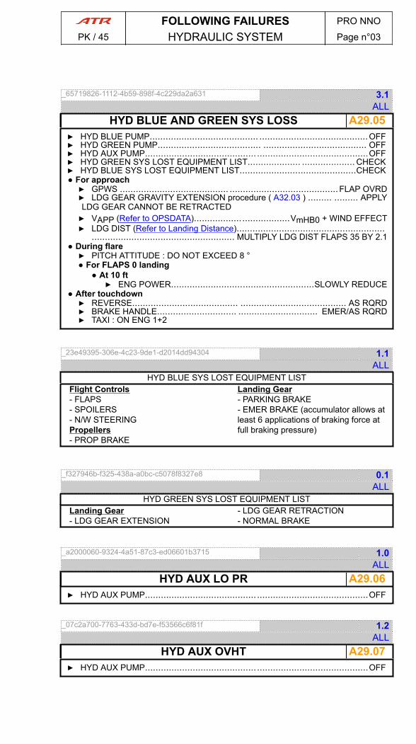
_65719826-1112-4b59-898f-4c229da2a631 3.1ALL
A29.05HYD BLUE AND GREEN SYS LOSS▶ HYD BLUE PUMP......................................... .........................................OFF▶ HYD GREEN PUMP....................................... ....................................... OFF▶ HYD AUX PUMP.......................................... ..........................................OFF▶ HYD GREEN SYS LOST EQUIPMENT LIST.................... .................... CHECK▶ HYD BLUE SYS LOST EQUIPMENT LIST............................................CHECK● For approach▶ GPWS ......................................... .........................................FLAP OVRD▶ LDG GEAR GRAVITY EXTENSION procedure ( A32.03 ) ......... ......... APPLYLDG GEAR CANNOT BE RETRACTED▶ VAPP (Refer to OPSDATA)....................................VmHB0 + WIND EFFECT▶ LDG DIST (Refer to Landing Distance)........................................................
...................................................... MULTIPLY LDG DIST FLAPS 35 BY 2.1● During flare▶ PITCH ATTITUDE : DO NOT EXCEED 8 °● For FLAPS 0 landing
● At 10 ft▶ ENG POWER......................................................SLOWLY REDUCE
● After touchdown▶ REVERSE........................................ ........................................ AS RQRD▶ BRAKE HANDLE.............................. .............................. EMER/AS RQRD▶ TAXI : ON ENG 1+2
_23e49395-306e-4c23-9de1-d2014dd94304 1.1ALL
HYD BLUE SYS LOST EQUIPMENT LISTFlight Controls- FLAPS- SPOILERS- N/W STEERINGPropellers- PROP BRAKE
Landing Gear- PARKING BRAKE- EMER BRAKE (accumulator allows atleast 6 applications of braking force atfull braking pressure)
_f327946b-f325-438a-a0bc-c5078f8327e8 0.1ALL
HYD GREEN SYS LOST EQUIPMENT LISTLanding Gear- LDG GEAR EXTENSION
- LDG GEAR RETRACTION- NORMAL BRAKE
_a2000060-9324-4a51-87c3-ed06601b3715 1.0ALL
A29.06HYD AUX LO PR▶ HYD AUX PUMP.......................................... ..........................................OFF
_07c2a700-7763-433d-bd7e-f53566c6f81f 1.2ALL
A29.07HYD AUX OVHT▶ HYD AUX PUMP.......................................... ..........................................OFF
FOLLOWING FAILURES PRO NNO
PK / 45 HYDRAULIC SYSTEM Page n°03

PAGE
INTENTIONALLY
LEFT BLANK
FOLLOWING FAILURES PRO NNO
PK / 45 HYDRAULIC SYSTEM Page n°04
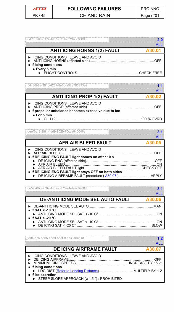
_6d786588-d174-4815-8719-f57398c6c063 2.0ALL
A30.01ANTI ICING HORNS 1(2) FAULT▶ ICING CONDITIONS : LEAVE AND AVOID▶ ANTI ICING HORNS (affected side)..........................................................OFF■ If icing conditions
● Every 5 min▶ FLIGHT CONTROLS........................................................CHECK FREE
_54c30b8a-391c-4267-8e6b-a52e783893e2 1.1ALL
A30.02ANTI ICING PROP 1(2) FAULT▶ ICING CONDITIONS : LEAVE AND AVOID▶ ANTI ICING PROP (affected side).............................. ..............................OFF■ If propeller unbalance becomes excessive due to ice
● For 5 min▶ CL 1+2............................................................................ 100 % OVRD
_deef5c13-8f91-4dd9-8029-70cca940046a 3.1ALL
A30.05AFR AIR BLEED FAULT▶ ICING CONDITIONS : LEAVE AND AVOID▶ AFR AIR BLEED.......................................... .......................................... OFF■ If DE ICING ENG FAULT light comes on after 10 s▶ DE ICING ENG (affected side)..............................................................OFF▶ AFR AIR BLEED......................................... .........................................ON▶ AFR AIR BLEED FAULT light......................... ......................... CHECK OFF
■ If DE ICING ENG FAULT light stays OFF on both sides▶ DE ICING AIRFRAME FAULT procedure ( A30.07 ) ............................APPLY
_0e5926b3-770a-451e-8873-24efa7c0e08d 3.1ALL
A30.06DE-ANTI ICING MODE SEL AUTO FAULT▶ DE-ANTI ICING MODE SEL AUTO..........................................................MAN■ If SAT < -10 °C▶ ANTI ICING MODE SEL SAT < -10 C° ......................... ......................... ON
■ If SAT < -20 °C▶ ANTI ICING MODE SEL SAT < -10 C° ......................... ......................... ON▶ DE ICING SAT < -20 C° ................................. ................................. SLOW
_f8df9576-e355-4689-b58f-09fc3345c31d 1.2ALL
A30.07DE ICING AIRFRAME FAULT▶ ICING CONDITIONS : LEAVE AND AVOID▶ DE ICING AIRFRAME...................................... ...................................... OFF▶ MINIMUM ICING SPEEDS................................................INCREASE BY 15 kt■ If icing conditions▶ LDG DIST (Refer to Landing Distance)............... ............... MULTIPLY BY 1.2
■ If ice accretion▶ STEEP SLOPE APPROACH (≥ 4.5 °) : PROHIBITED
FOLLOWING FAILURES PRO NNO
PK / 45 ICE AND RAIN Page n°01

_a3c11962-054d-4095-88a2-a5efb3de1ffb 2.1ALL
A30.08 DE ICING MODE SEL FAULT▶ DE ICING MODE SEL.................................... .................................... OVRD▶ DE ICING : MONITOR■ If ENG 1(2) FLAME OUT in flight▶ DE ICING MODE SEL ............................. ............................. RELEASE PB
_d59bcb90-dd29-4d71-b5a6-2a21423d324e 0.2ALL
A30.09 DE ICING ENG 1(2) FAULT▶ ICING CONDITIONS : LEAVE AND AVOID▶ ENG (affected) PARAMETERS : MONITOR▶ DE ICING ENG (affected side)................................ ................................ OFF
_65c9911d-508d-4fd0-807a-4ac525b07789 1.1ALL
A30.10 ICE DETECT FAULT▶ ICE ACCRETION : MONITOR
_3cb3a943-91e3-44cc-9a49-1f0f6e3a4df5 1.1ALL
A30.11 PROBES HTG FAILURE■ If one CAPT/FO ALPHA PROBE HTG comes on▶ STICK PUSHER / SHAKER : MONITOR
■ If both CAPT/FO ALPHA PROBE HTG come on▶ STICK PUSHER-SHAKER FAULT procedure ( A27.13 ) ......................APPLY
■ If any CAPT/FO PITOT/STAT/TAT PROBE HTG comes on▶ ADC SW.................................. ..................................SELECT VALID ADC▶ ASSOCIATED INDICATION : MONITOR▶ ILS CAT 2 : PROHIBITED
■ If any STBY PITOT/STAT PROBE HTG comes on▶ STBY IAS and ALT indications........................ ........................ DISREGARD
_bda1a265-203e-4bc5-95f3-1f274809e68b 1.1ALL
A30.12 SIDE WINDOW HTG FAULT▶ SIDE WINDOW pb ........................................ ........................................ OFF
_840d2980-2ea8-43ce-96c0-846d61ed2af6 1.3ALL
A30.13 WINDSHIELD HTG FAULT▶ WINDSHIELD HTG pb (affected side)........................... ........................... OFF
FOLLOWING FAILURES PRO NNO
PK / 45 ICE AND RAIN Page n°02
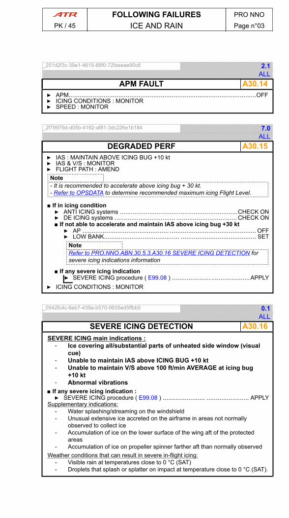
_251d2f3c-39e1-4615-88f0-72faeeae90c6 2.1ALL
A30.14APM FAULT▶ APM......................................................................................................OFF▶ ICING CONDITIONS : MONITOR▶ SPEED : MONITOR
_2f79979d-d05b-4192-af81-3dc226e1b184 7.0ALL
A30.15DEGRADED PERF▶ IAS : MAINTAIN ABOVE ICING BUG +10 kt▶ IAS & V/S : MONITOR▶ FLIGHT PATH : AMEND
Note- It is recommended to accelerate above icing bug + 30 kt.- Refer to OPSDATA to determine recommended maximum icing Flight Level.
■ If in icing condition▶ ANTI ICING systems ................................................................CHECK ON▶ DE ICING systems ................................. ................................. CHECK ON■ If not able to accelerate and maintain IAS above icing bug +30 kt▶ AP ............................................... ............................................... OFF▶ LOW BANK......................................... ......................................... SET
NoteRefer to PRO.NNO.ABN.30.5.3.A30.16 SEVERE ICING DETECTION forsevere icing indications information
■ If any severe icing indication▶ SEVERE ICING procedure ( E99.08 ) ..................... .....................APPLY
▶ ICING CONDITIONS : MONITOR
_0542fc4c-6eb7-439a-b570-9935ed5ffbb0 0.1ALL
A30.16SEVERE ICING DETECTIONSEVERE ICING main indications :
- Ice covering all/substantial parts of unheated side window (visualcue)
- Unable to maintain IAS above ICING BUG +10 kt- Unable to maintain V/S above 100 ft/min AVERAGE at icing bug
+10 kt- Abnormal vibrations
■ If any severe icing indication :▶ SEVERE ICING procedure ( E99.08 ) ....................... ....................... APPLY
Supplementary indications:- Water splashing/streaming on the windshield- Unusual extensive ice accreted on the airframe in areas not normally
observed to collect ice- Accumulation of ice on the lower surface of the wing aft of the protected
areas- Accumulation of ice on propeller spinner farther aft than normally observed
Weather conditions that can result in severe in-flight icing:- Visible rain at temperatures close to 0 °C (SAT)- Droplets that splash or splatter on impact at temperature close to 0 °C (SAT).
FOLLOWING FAILURES PRO NNO
PK / 45 ICE AND RAIN Page n°03
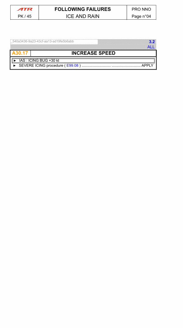
_540a3436-9a23-43cf-aa13-ad19fe5b6abb 3.2ALL
A30.17 INCREASE SPEED▶ IAS : ICING BUG +30 kt▶ SEVERE ICING procedure ( E99.08 ) ......................... ......................... APPLY
FOLLOWING FAILURES PRO NNO
PK / 45 ICE AND RAIN Page n°04
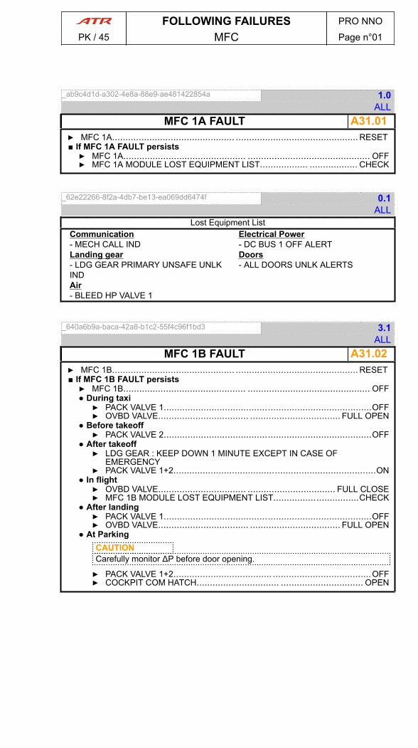
_ab9c4d1d-a302-4e8a-88e9-ae481422854a 1.0ALL
A31.01MFC 1A FAULT▶ MFC 1A.............................................. .............................................. RESET■ If MFC 1A FAULT persists▶ MFC 1A.............................................. .............................................. OFF▶ MFC 1A MODULE LOST EQUIPMENT LIST.................. .................. CHECK
_62e22266-8f2a-4db7-be13-ea069dd6474f 0.1ALL
Lost Equipment ListCommunication- MECH CALL INDLanding gear- LDG GEAR PRIMARY UNSAFE UNLKINDAir- BLEED HP VALVE 1
Electrical Power- DC BUS 1 OFF ALERTDoors- ALL DOORS UNLK ALERTS
_640a6b9a-baca-42a8-b1c2-55f4c96f1bd3 3.1ALL
A31.02MFC 1B FAULT▶ MFC 1B.............................................. .............................................. RESET■ If MFC 1B FAULT persists▶ MFC 1B.............................................. .............................................. OFF● During taxi▶ PACK VALVE 1..............................................................................OFF▶ OVBD VALVE.................................. .................................. FULL OPEN
● Before takeoff▶ PACK VALVE 2..............................................................................OFF
● After takeoff▶ LDG GEAR : KEEP DOWN 1 MINUTE EXCEPT IN CASE OF
EMERGENCY▶ PACK VALVE 1+2............................................................................ON
● In flight▶ OVBD VALVE................................. ................................. FULL CLOSE▶ MFC 1B MODULE LOST EQUIPMENT LIST................................CHECK
● After landing▶ PACK VALVE 1..............................................................................OFF▶ OVBD VALVE.................................. .................................. FULL OPEN
● At ParkingCAUTIONCarefully monitor ΔP before door opening.
▶ PACK VALVE 1+2..................................... .....................................OFF▶ COCKPIT COM HATCH............................... ............................... OPEN
FOLLOWING FAILURES PRO NNO
PK / 45 MFC Page n°01
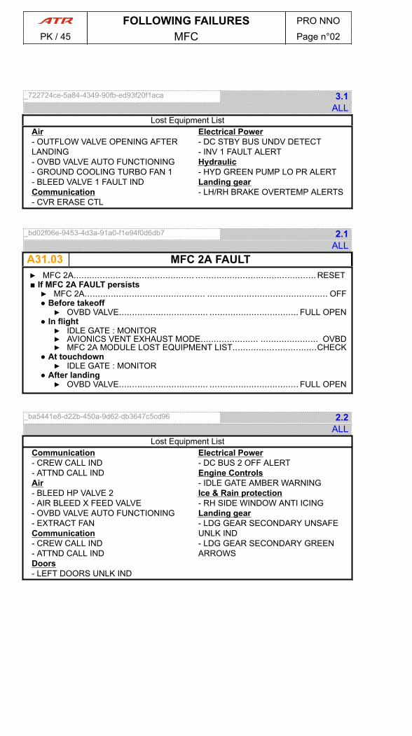
_722724ce-5a84-4349-90fb-ed93f20f1aca 3.1ALL
Lost Equipment ListAir- OUTFLOW VALVE OPENING AFTERLANDING- OVBD VALVE AUTO FUNCTIONING- GROUND COOLING TURBO FAN 1- BLEED VALVE 1 FAULT INDCommunication- CVR ERASE CTL
Electrical Power- DC STBY BUS UNDV DETECT- INV 1 FAULT ALERTHydraulic- HYD GREEN PUMP LO PR ALERTLanding gear- LH/RH BRAKE OVERTEMP ALERTS
_bd02f06e-9453-4d3a-91a0-f1e94f0d6db7 2.1ALL
A31.03 MFC 2A FAULT▶ MFC 2A.............................................. .............................................. RESET■ If MFC 2A FAULT persists▶ MFC 2A.............................................. .............................................. OFF● Before takeoff▶ OVBD VALVE.................................. .................................. FULL OPEN
● In flight▶ IDLE GATE : MONITOR▶ AVIONICS VENT EXHAUST MODE...................... ...................... OVBD▶ MFC 2A MODULE LOST EQUIPMENT LIST................................CHECK
● At touchdown▶ IDLE GATE : MONITOR
● After landing▶ OVBD VALVE.................................. .................................. FULL OPEN
_ba5441e8-d22b-450a-9d62-db3647c5cd96 2.2ALL
Lost Equipment ListCommunication- CREW CALL IND- ATTND CALL INDAir- BLEED HP VALVE 2- AIR BLEED X FEED VALVE- OVBD VALVE AUTO FUNCTIONING- EXTRACT FANCommunication- CREW CALL IND- ATTND CALL INDDoors- LEFT DOORS UNLK IND
Electrical Power- DC BUS 2 OFF ALERTEngine Controls- IDLE GATE AMBER WARNINGIce & Rain protection- RH SIDE WINDOW ANTI ICINGLanding gear- LDG GEAR SECONDARY UNSAFEUNLK IND- LDG GEAR SECONDARY GREENARROWS
FOLLOWING FAILURES PRO NNO
PK / 45 MFC Page n°02

_ab25f78f-57a0-42e3-8db4-9090459e9a05 3.1ALL
A31.04MFC 2B FAULT▶ MFC 2B.............................................. .............................................. RESET■ If MFC 2B FAULT persists▶ MFC 2B.............................................. .............................................. OFF● During taxi▶ PACK VALVE 2..............................................................................OFF▶ OVBD VALVE.................................. .................................. FULL OPEN
● Before takeoff▶ PACK VALVE 1..............................................................................OFF
● After takeoff▶ LDG GEAR : KEEP DOWN 1 MINUTE EXCEPT IN CASE OF
EMERGENCY▶ PACK VALVE 1+2............................................................................ON
● In flight▶ OVBD VALVE................................. ................................. FULL CLOSE▶ MFC 2B MODULE EQUIPMENT LIST.................... .................... CHECK
● After landing▶ PACK VALVE 2..............................................................................OFF▶ OVBD VALVE.................................. .................................. FULL OPEN
● At parkingCAUTIONCarefully monitor ΔP before door opening.
▶ PACK VALVE 1+2..................................... .....................................OFF▶ COCKPIT COM HATCH............................... ............................... OPEN
_f2f0b9e4-f0f8-40c2-b381-d7682b10139a 3.1ALL
Lost Equipment ListAir- OUTFLOW VALVE OPENING AFTERLANDING- AVIONICS VENT OVBD VALVE AUTOMODE- GROUND COOLING TURBO FAN 2- BLEED VALVE 2 FAULT INDElectrical Power- INV 2 FAULT ALERTIce & Rain protection- ICE DETECTION- ANTI ICING F/O SIDE WINDOW CTLAND IND
Landing gear- LDG GEAR SECONDARY UNSAFEUNLK IND- LDG GEAR SECONDARY GREENARROWS- BRAKE TEMP RH ALERT
FOLLOWING FAILURES PRO NNO
PK / 45 MFC Page n°03

_c3b23031-4c04-445e-841f-3ba6b59d160a 6.1ALL
A31.05 MFC 1A+1B FAULT▶ MFC 1A.............................................. .............................................. RESET● After MFC 1A RESET▶ MFC 1B............................................ ............................................ RESET
■ If one MFC module recovered▶ MFC (affected module) procedure.......................... .......................... APPLY
■ If MFC 1A + 1B Fault persist▶ MFC 1A + 1B......................................................................................OFF● Before takeoff▶ RETURN TO PARKING▶ PACK VALVE 1..............................................................................OFF▶ OVBD VALVE ....................................................................FULL OPEN
● In flight▶ ICING CONDITIONS : LEAVE AND AVOID▶ ANTI ICING PROP 1 .................................. .................................. OFF▶ ANTI ICING PROP 1(2) FAULT procedure ( A30.02 ) .......... .......... APPLY▶ DE ICING MODE SEL ................................................ OVRD AS RQRD▶ PACK VALVE 1 ...................................... ...................................... OFF▶ BLEED VALVE 1 ..................................... ..................................... OFF▶ OVBD VALVE ..................................................................FULL CLOSE▶ ENG BLEED 1(2) FAULT procedure ( A36.04 ) .............. .............. APPLY▶ WX RADAR......................................... ......................................... OFF▶ GPWS ............................................ ............................................ OFF▶ MFC 1A + 1B MODULES LOST EQUIPMENT LIST .......... .......... CHECK
● Before landing▶ ATPCS ............................................ ............................................OFF▶ VAPP (Refer to OPSDATA) .......... .......... NOT LESS THAN VmHB +10 kt▶ LDG DIST (Refer to Landing Distance) ........... ........... MULTIPLY BY 1.15▶ CL 1 + 2 ...................................... ...................................... MAX RPM
● After landing▶ OVBD VALVE.................................. .................................. FULL OPEN
● At ParkingCAUTIONCarefully monitor ΔP before door opening.
▶ PACK VALVE 2..............................................................................OFF▶ COCKPIT COM HATCH............................... ............................... OPEN
_ef01bcf3-25c9-419e-8234-e70a83a7e168 2.1ALL
Lost Equipment ListAir- OUTFLOW VALVE OPENING AFTERLANDING- AVIONICS VENT OVBD VALVE AUTOMODE- GROUND COOLING TURBO FAN 1- BLEED VALVE 1 AND FAULT IND- PACK VALVE 1 CTL AND FAULT INDCommunications- MECH CALL IND- CVR ERASE CTLDoors- DOORS UNLK INDElectrical Power- DC STBY BUS UNDV DETECTION- DC BUS 1 OFF ALERT- AC BUS 1 SPLY- INV 1 FAULT ALERT
Engines- ENG 1 UPTRIM- ENG 1 AUTO FEATHERFlight controls- STICK PUSHER CTL AND INDHydraulic- HYD GREEN PUMP LO PR ALERTIce and Rain protection- ANTI ICING PROP 1 CTL AND FAULTIND- DE ICING AIRFRAME (normal mode)- ANTI ICING CAPT SIDE WINDOWCTL AND FAULT INDLanding gear- LDG GEAR PRIMARY UNSAFE UNLKIND- LDG GEAR PRIMARY GREENARROWS- BRAKE TEMP ALERT
FOLLOWING FAILURES PRO NNO
PK / 45 MFC Page n°04
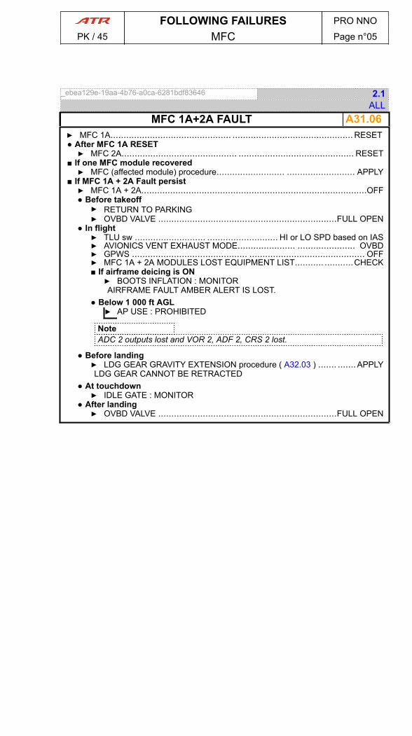
_ebea129e-19aa-4b76-a0ca-6281bdf83646 2.1ALL
A31.06MFC 1A+2A FAULT▶ MFC 1A.............................................. .............................................. RESET● After MFC 1A RESET▶ MFC 2A............................................ ............................................ RESET
■ If one MFC module recovered▶ MFC (affected module) procedure.......................... .......................... APPLY
■ If MFC 1A + 2A Fault persist▶ MFC 1A + 2A......................................................................................OFF● Before takeoff▶ RETURN TO PARKING▶ OVBD VALVE ....................................................................FULL OPEN
● In flight▶ TLU sw ........................... ........................... HI or LO SPD based on IAS▶ AVIONICS VENT EXHAUST MODE...................... ...................... OVBD▶ GPWS ............................................ ............................................ OFF▶ MFC 1A + 2A MODULES LOST EQUIPMENT LIST........... ...........CHECK■ If airframe deicing is ON▶ BOOTS INFLATION : MONITORAIRFRAME FAULT AMBER ALERT IS LOST.
● Below 1 000 ft AGL▶ AP USE : PROHIBITED
NoteADC 2 outputs lost and VOR 2, ADF 2, CRS 2 lost.
● Before landing▶ LDG GEAR GRAVITY EXTENSION procedure ( A32.03 ) ....... .......APPLYLDG GEAR CANNOT BE RETRACTED
● At touchdown▶ IDLE GATE : MONITOR
● After landing▶ OVBD VALVE ....................................................................FULL OPEN
FOLLOWING FAILURES PRO NNO
PK / 45 MFC Page n°05

_1deb9897-3103-4dc2-8509-047c5ddd9b08 2.1ALL
Lost Equipment ListAir- AIR X VALVE- AVIONICS VENT OVBD VALVE AUTOMODE- EXTRACT FAN- BLEED HP VALVE 1 + 2Autopilot- AP OFF WARNING LIGHT- ALTITUDE ALERT LIGHT- GUIDANCE LIGHTCommunications- MECHANIC CALL IND- ATTND CALL IND- CREW CALL IND- RECORDERS (START/STOP)Electrical Power- DC BUS 1 + 2 OFF WARNING- AC BUS 1 + 2 SPLY- INV 1 + 2 FAULT LIGHT- EMER BAT CHG CTLFlight controls- FLAPS UNLK WARNING- STICK PUSHER / SHAKER FAULTIND- Releasable Centering Unit AUTODISCONNECT after YAW TRIM actionor YD engagement- TLU FAULT LIGHT- TRIPLE TRIM IND- AIL LOCK LIGHT- CCAS WARNING ALERT (FLAPUNLK)
Ice and Rain protection- DE ICING AIRFRAME FAULT- RH SIDE WINDOW ANTI ICINGLanding gear- LDG GEAR CTL- LDG GEAR PRIMARY UNLK IND- LDG GEAR SECONDARY UNLK IND- LDG GEAR PRIMARY GREENARROWS- LDG GEAR SECONDARY GREENARROWSLights- LIGHT TESTDoors- DOOR UNLK ALERTEngines- IDLE GATE and associated AMBERWARNING
FOLLOWING FAILURES PRO NNO
PK / 45 MFC Page n°06
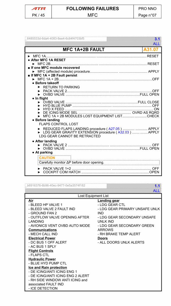
_6485533d-6da4-4083-8ee4-6c64f4703bf5 3.1ALL
A31.07MFC 1A+2B FAULT▶ MFC 1A.............................................. .............................................. RESET● After MFC 1A RESET▶ MFC 2B............................................ ............................................ RESET
■ If one MFC module recovered▶ MFC (affected module) procedure.......................... .......................... APPLY
■ If MFC 1A + 2B Fault persist▶ MFC 1A + 2B......................................................................................OFF● Before takeoff▶ RETURN TO PARKING▶ PACK VALVE 2..............................................................................OFF▶ OVBD VALVE ....................................................................FULL OPEN
● In flight▶ OVBD VALVE ..................................................................FULL CLOSE▶ HYD BLUE PUMP .................................... .................................... OFF▶ HYD X FEED ........................................ ........................................ ON▶ DE ICING MODE SEL ................................................ OVRD AS RQRD▶ MFC 1A + 2B MODULES LOST EQUIPMENT LIST........... ...........CHECK
● Before landingFLAPS CONTROL LOST▶ REDUCED FLAPS LANDING procedure ( A27.05 ) ........... ........... APPLY▶ LDG GEAR GRAVITY EXTENSION procedure ( A32.03 ) ....... .......APPLYLDG GEAR CANNOT BE RETRACTED
● After landing▶ PACK VALVE 2 ...................................... ...................................... OFF▶ OVBD VALVE ....................................................................FULL OPEN
● At parkingCAUTIONCarefully monitor ΔP before door opening.
▶ PACK VALVE 1+2 .................................... .................................... OFF▶ COCKPIT COM HATCH ..............................................................OPEN
_b6916376-6b96-40ec-9477-0e5a3574f182 1.1ALL
Lost Equipment ListAir- BLEED HP VALVE 1- BLEED VALVE 2 FAULT IND- GROUND FAN 2- OUTFLOW VALVE OPENING AFTERLANDING- AVIONICS VENT OVBD AUTO MODECommunications- MECH CALL INDElectrical Power- DC BUS 1 OFF ALERT- AC BUS 1 SPLYFlight Controls- FLAPS CTLHydraulic Power- BLUE HYD PUMP CTLIce and Rain protection- DE ICING/ANTI ICING ENG 1- DE ICING/ANTI ICING ENG 2 ALERT- RH SIDE WINDOW ANTI ICING andassociated FAULT IND- ICE DETECTION
Landing gear- LDG GEAR CTL- LDG GEAR PRIMARY UNSAFE UNLKIND- LDG GEAR SECONDARY UNSAFEUNLK IND- LDG GEAR SECONDARY GREENARROWS- RH BRAKE TEMP ALERTDoors- ALL DOORS UNLK ALERTS
FOLLOWING FAILURES PRO NNO
PK / 45 MFC Page n°07

_213bd2d9-5e9b-4045-a195-aa7a53863dc7 4.1ALL
A31.08 MFC 1B+2A FAULT▶ MFC 1B.............................................. .............................................. RESET● After MFC 1B RESET▶ MFC 2A............................................ ............................................ RESET
■ If one MFC module recovered▶ MFC (affected module) procedure.......................... .......................... APPLY
■ If MFC 1B + 2A Fault persist▶ MFC 1B + 2A......................................................................................OFF● Before takeoff▶ RETURN TO PARKING▶ PACK VALVE 1..............................................................................OFF▶ OVBD VALVE ....................................................................FULL OPEN
● In flight▶ AVIONICS VENT EXHAUST MODE...................... ...................... OVBD▶ DE ICING MODE SEL ................................................ OVRD AS RQRD▶ MFC 1B + 2A MODULES LOST EQUIPMENT LIST........... ...........CHECK
NoteF/O IAS indicator is lost and VOR 2, ADF 2, CRS 2 not available on RMI 2.
● Before landingFLAPS CONTROL LOST▶ REDUCED FLAPS LANDING procedure ( A27.05 ) ........... ........... APPLY▶ LDG GEAR GRAVITY EXTENSION procedure ( A32.03 ) ....... .......APPLYLDG GEAR CANNOT BE RETRACTED
● At touchdown▶ IDLE GATE : MONITOR
● After landing▶ PACK VALVE 1 ...................................... ...................................... OFF▶ OVBD VALVE ....................................................................FULL OPEN
● At parkingCAUTIONCarefully monitor ΔP before door opening.
▶ PACK VALVE 2 ...................................... ...................................... OFF▶ COCKPIT COM HATCH ..............................................................OPEN
FOLLOWING FAILURES PRO NNO
PK / 45 MFC Page n°08
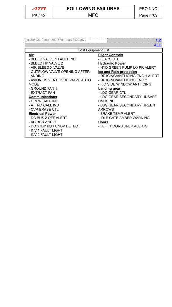
_cc8e8023-2ade-4352-87da-a9e72820ad7c 1.2ALL
Lost Equipment ListAir- BLEED VALVE 1 FAULT IND- BLEED HP VALVE 2- AIR BLEED X VALVE- OUTFLOW VALVE OPENING AFTERLANDING- AVIONICS VENT OVBD VALVE AUTOMODE- GROUND FAN 1- EXTRACT FANCommunications- CREW CALL IND- ATTND CALL IND- CVR ERASE CTLElectrical Power- DC BUS 2 OFF ALERT- AC BUS 2 SPLY- DC STBY BUS UNDV DETECT- INV 1 FAULT LIGHT- INV 2 FAULT LIGHT
Flight Controls- FLAPS CTLHydraulic Power- HYD GREEN PUMP LO PR ALERTIce and Rain protection- DE ICING/ANTI ICING ENG 1 ALERT- DE ICING/ANTI ICING ENG 2- F/O SIDE WINDOW ANTI ICINGLanding gear- LDG GEAR CTL- LDG GEAR SECONDARY UNSAFEUNLK IND- LDG GEAR SECONDARY GREENARROWS- BRAKE TEMP ALERT- IDLE GATE AMBER WARNINGDoors- LEFT DOORS UNLK ALERTS
FOLLOWING FAILURES PRO NNO
PK / 45 MFC Page n°09

_58665077-f058-4155-b1c0-220d4ae9b6df 4.1ALL
A31.09 MFC 1B+2B FAULT▶ MFC 1B.............................................. .............................................. RESET● After MFC 1B RESET▶ MFC 2B............................................ ............................................ RESET
■ If one MFC module recovered▶ MFC (affected module) procedure.......................... .......................... APPLY
■ If MFC 1B + 2B Fault persist▶ MFC 1B + 2B......................................................................................OFF● Before takeoff▶ RETURN TO PARKING▶ PACK VALVE 1+2..................................... .....................................OFF▶ OVBD VALVE ....................................................................FULL OPEN
● In flight▶ OVERHEAD panel : MONITOR▶ MFC 1B + 2B MODULES LOST EQUIPMENT LIST........... ...........CHECK
● Before landingNoteATPCS operates, only ARM light inhibited.
▶ N/W STEERING ..................................... ..................................... OFF▶ LDG GEAR GRAVITY EXTENSION procedure ( A32.03 ) ....... .......APPLYLDG GEAR CANNOT BE RETRACTED.
● After touchdown▶ IDLE GATE lever .................................... .................................... PULL▶ DIFFERENTIAL BRAKING .............................. .............................. USE
● After landing▶ OVBD VALVE ....................................................................FULL OPEN▶ ANTI ICING HORNS .............................. .............................. RELEASE▶ PROBE HTG ................................................................................OFF
● At ParkingCAUTIONCarefully monitor ΔP before door opening.
▶ PACK VALVE 1+2 .................................... .................................... OFF▶ COCKPIT COM HATCH ..............................................................OPEN
NoteExternal power cannot be used.
FOLLOWING FAILURES PRO NNO
PK / 45 MFC Page n°10
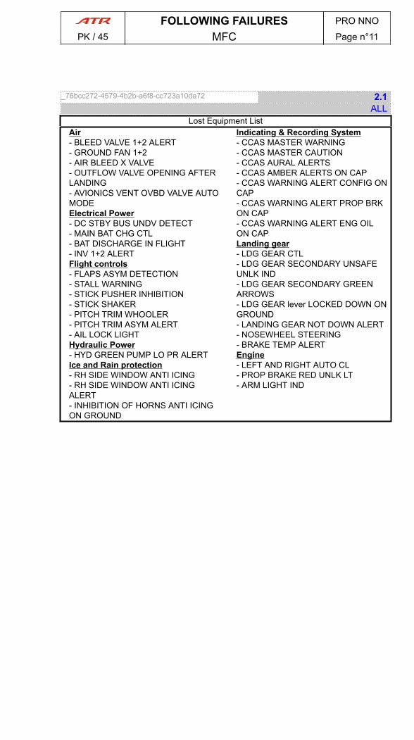
_76bcc272-4579-4b2b-a6f8-cc723a10da72 2.1ALL
Lost Equipment ListAir- BLEED VALVE 1+2 ALERT- GROUND FAN 1+2- AIR BLEED X VALVE- OUTFLOW VALVE OPENING AFTERLANDING- AVIONICS VENT OVBD VALVE AUTOMODEElectrical Power- DC STBY BUS UNDV DETECT- MAIN BAT CHG CTL- BAT DISCHARGE IN FLIGHT- INV 1+2 ALERTFlight controls- FLAPS ASYM DETECTION- STALL WARNING- STICK PUSHER INHIBITION- STICK SHAKER- PITCH TRIM WHOOLER- PITCH TRIM ASYM ALERT- AIL LOCK LIGHTHydraulic Power- HYD GREEN PUMP LO PR ALERTIce and Rain protection- RH SIDE WINDOW ANTI ICING- RH SIDE WINDOW ANTI ICINGALERT- INHIBITION OF HORNS ANTI ICINGON GROUND
Indicating & Recording System- CCAS MASTER WARNING- CCAS MASTER CAUTION- CCAS AURAL ALERTS- CCAS AMBER ALERTS ON CAP- CCAS WARNING ALERT CONFIG ONCAP- CCAS WARNING ALERT PROP BRKON CAP- CCAS WARNING ALERT ENG OILON CAPLanding gear- LDG GEAR CTL- LDG GEAR SECONDARY UNSAFEUNLK IND- LDG GEAR SECONDARY GREENARROWS- LDG GEAR lever LOCKED DOWN ONGROUND- LANDING GEAR NOT DOWN ALERT- NOSEWHEEL STEERING- BRAKE TEMP ALERTEngine- LEFT AND RIGHT AUTO CL- PROP BRAKE RED UNLK LT- ARM LIGHT IND
FOLLOWING FAILURES PRO NNO
PK / 45 MFC Page n°11

_6c4f6e9c-c3ec-4d27-bc3e-19c260b9e42a 6.1ALL
A31.10 MFC 2A+2B FAULT▶ MFC 2A.............................................. .............................................. RESET● After MFC 2A RESET▶ MFC 2B............................................ ............................................ RESET
■ If one MFC module recovered▶ MFC (affected module) procedure.......................... .......................... APPLY
■ If MFC 2A + 2B Fault persist▶ MFC 2A + 2B......................................................................................OFF● Before takeoff▶ RETURN TO PARKING▶ BLEED VALVE 2............................................................................OFF▶ PACK VALVE 2..............................................................................OFF▶ OVBD VALVE ....................................................................FULL OPEN
● In flight▶ ICING CONDITIONS : LEAVE AND AVOID▶ AVIONICS VENT EXHAUST MODE...................... ...................... OVBD▶ ANTI ICING PROP 2 .................................. .................................. OFF▶ ANTI ICING PROP 1(2) FAULT procedure ( A30.02 ) .......... .......... APPLY▶ DE ICING MODE SEL ................................................ OVRD AS RQRD▶ PACK VALVE 2 ...................................... ...................................... OFF▶ BLEED VALVE 2............................................................................OFF▶ ENG BLEED 1(2) FAULT procedure ( A36.04 ) .............. .............. APPLY▶ MFC 2A + 2B MODULES LOST EQUIPMENT LIST .......... .......... CHECK
● Before landing▶ ATPCS ............................................ ............................................OFF▶ VAPP (Refer to OPSDATA)........... ...........NOT LESS THAN VmHB +10 kt▶ LDG DIST (Refer to Landing Distance)........................MULTIPLY BY 1.15
● At touchdown▶ IDLE GATE : MONITOR
● After landing▶ OVBD VALVE ....................................................................FULL OPEN
● At ParkingCAUTIONCarefully monitor ΔP before door opening.
▶ PACK VALVE 1..............................................................................OFF▶ COCKPIT COM HATCH............................... ............................... OPEN
FOLLOWING FAILURES PRO NNO
PK / 45 MFC Page n°12
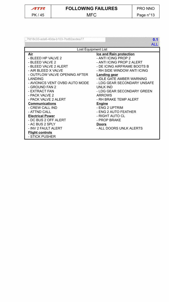
_7fd18c33-ada6-40da-b103-7bd82acdea77 0.1ALL
Lost Equipment ListAir- BLEED HP VALVE 2- BLEED VALVE 2- BLEED VALVE 2 ALERT- AIR BLEED X VALVE- OUTFLOW VALVE OPENING AFTERLANDING- AVIONICS VENT OVBD AUTO MODE- GROUND FAN 2- EXTRACT FAN- PACK VALVE 2- PACK VALVE 2 ALERTCommunications- CREW CALL IND- ATTND CALLElectrical Power- DC BUS 2 OFF ALERT- AC BUS 2 SPLY- INV 2 FAULT ALERTFlight controls- STICK PUSHER
Ice and Rain protection- ANTI ICING PROP 2- ANTI ICING PROP 2 ALERT- DE ICING AIRFRAME BOOTS B- RH SIDE WINDOW ANTI ICINGLanding gear- IDLE GATE AMBER WARNING- LDG GEAR SECONDARY UNSAFEUNLK IND- LDG GEAR SECONDARY GREENARROWS- RH BRAKE TEMP ALERTEngine- ENG 2 UPTRIM- ENG 2 AUTO FEATHER- RIGHT AUTO CL- PROP BRAKEDoors- ALL DOORS UNLK ALERTS
FOLLOWING FAILURES PRO NNO
PK / 45 MFC Page n°13

PAGE
INTENTIONALLY
LEFT BLANK
FOLLOWING FAILURES PRO NNO
PK / 45 MFC Page n°14
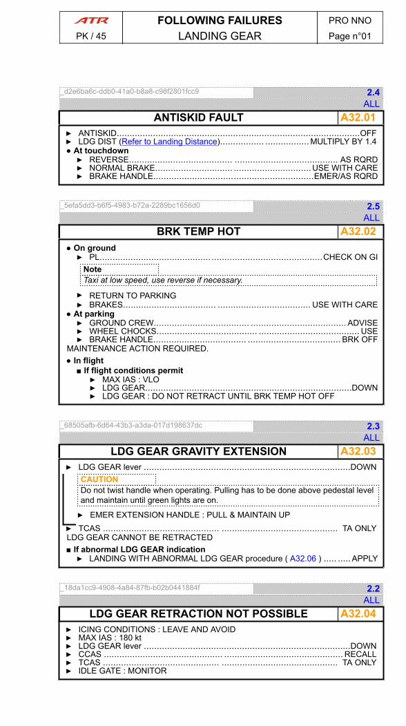
_d2e6ba6c-ddb0-41a0-b8a8-c98f2801fcc9 2.4ALL
A32.01ANTISKID FAULT▶ ANTISKID..............................................................................................OFF▶ LDG DIST (Refer to Landing Distance)................. ................. MULTIPLY BY 1.4● At touchdown▶ REVERSE........................................ ........................................ AS RQRD▶ NORMAL BRAKE.............................. ..............................USE WITH CARE▶ BRAKE HANDLE..............................................................EMER/AS RQRD
_5efa5dd3-b6f5-4983-b72a-2289bc1656d0 2.5ALL
A32.02BRK TEMP HOT● On ground▶ PL......................................................................................CHECK ON GI
NoteTaxi at low speed, use reverse if necessary.
▶ RETURN TO PARKING▶ BRAKES.................................... .................................... USE WITH CARE
● At parking▶ GROUND CREW..................................... ..................................... ADVISE▶ WHEEL CHOCKS....................................... ....................................... USE▶ BRAKE HANDLE.................................... .................................... BRK OFF
MAINTENANCE ACTION REQUIRED.● In flight
■ If flight conditions permit▶ MAX IAS : VLO▶ LDG GEAR................................................................................DOWN▶ LDG GEAR : DO NOT RETRACT UNTIL BRK TEMP HOT OFF
_68505afb-6d64-43b3-a3da-017d198637dc 2.3ALL
A32.03LDG GEAR GRAVITY EXTENSION▶ LDG GEAR lever ................................................................................DOWN
CAUTIONDo not twist handle when operating. Pulling has to be done above pedestal leveland maintain until green lights are on.
▶ EMER EXTENSION HANDLE : PULL & MAINTAIN UP▶ TCAS ............................................. ............................................. TA ONLYLDG GEAR CANNOT BE RETRACTED■ If abnormal LDG GEAR indication▶ LANDING WITH ABNORMAL LDG GEAR procedure ( A32.06 ) ..... ..... APPLY
_18da1cc9-4908-4a84-87fb-b02b0441884f 2.2ALL
A32.04LDG GEAR RETRACTION NOT POSSIBLE▶ ICING CONDITIONS : LEAVE AND AVOID▶ MAX IAS : 180 kt▶ LDG GEAR lever ................................................................................DOWN▶ CCAS .............................................. .............................................. RECALL▶ TCAS ............................................. ............................................. TA ONLY▶ IDLE GATE : MONITOR
FOLLOWING FAILURES PRO NNO
PK / 45 LANDING GEAR Page n°01
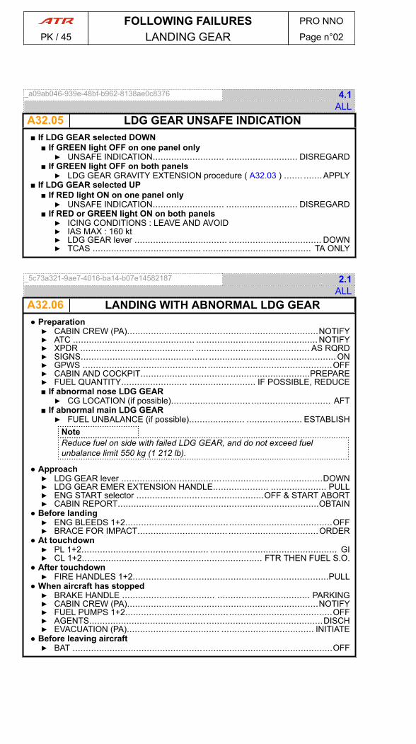
_a09ab046-939e-48bf-b962-8138ae0c8376 4.1ALL
A32.05 LDG GEAR UNSAFE INDICATION■ If LDG GEAR selected DOWN
■ If GREEN light OFF on one panel only▶ UNSAFE INDICATION........................... ........................... DISREGARD
■ If GREEN light OFF on both panels▶ LDG GEAR GRAVITY EXTENSION procedure ( A32.03 ) ....... .......APPLY
■ If LDG GEAR selected UP■ If RED light ON on one panel only▶ UNSAFE INDICATION........................... ........................... DISREGARD
■ If RED or GREEN light ON on both panels▶ ICING CONDITIONS : LEAVE AND AVOID▶ IAS MAX : 160 kt▶ LDG GEAR lever ................................... ................................... DOWN▶ TCAS ......................................... ......................................... TA ONLY
_5c73a321-9ae7-4016-ba14-b07e14582187 2.1ALL
A32.06 LANDING WITH ABNORMAL LDG GEAR● Preparation▶ CABIN CREW (PA)........................................................................NOTIFY▶ ATC .............................................. ..............................................NOTIFY▶ XPDR ........................................... ........................................... AS RQRD▶ SIGNS................................................ ................................................ON▶ GPWS ..............................................................................................OFF▶ CABIN AND COCKPIT................................................................PREPARE▶ FUEL QUANTITY......................... ......................... IF POSSIBLE, REDUCE■ If abnormal nose LDG GEAR▶ CG LOCATION (if possible).............................. .............................. AFT
■ If abnormal main LDG GEAR▶ FUEL UNBALANCE (if possible)..................... ..................... ESTABLISH
NoteReduce fuel on side with failed LDG GEAR, and do not exceed fuelunbalance limit 550 kg (1 212 lb).
● Approach▶ LDG GEAR lever ............................................................................DOWN▶ LDG GEAR EMER EXTENSION HANDLE..................... ..................... PULL▶ ENG START selector ................................................OFF & START ABORT▶ CABIN REPORT............................................................................OBTAIN
● Before landing▶ ENG BLEEDS 1+2..............................................................................OFF▶ BRACE FOR IMPACT.................................. ..................................ORDER
● At touchdown▶ PL 1+2................................................ ................................................ GI▶ CL 1+2.................................................................... FTR THEN FUEL S.O.
● After touchdown▶ FIRE HANDLES 1+2..........................................................................PULL
● When aircraft has stopped▶ BRAKE HANDLE ................................... ................................... PARKING▶ CABIN CREW (PA)........................................................................NOTIFY▶ FUEL PUMPS 1+2..............................................................................OFF▶ AGENTS........................................................................................DISCH▶ EVACUATION (PA)................................... ................................... INITIATE
● Before leaving aircraft▶ BAT ..................................................................................................OFF
FOLLOWING FAILURES PRO NNO
PK / 45 LANDING GEAR Page n°02

_951875ee-1850-48bf-9ddd-2792f4834a18 1.1ALL
A34.01ADC 1(2) FAILURE▶ ADC sw.................................... .................................... SELECT VALID ADC▶ AP CPL pb ........................................................................OPERATIVE SIDEAP/FD UPPER MODE CAN BE REENGAGED▶ ATC sw..........................................................................SELECT VALID ADC■ If ADC 1 FAILED▶ GPWS............................................... ............................................... OFF▶ LANDING ELEVATION .................. .................. SET PRESSURE ALTITUDE
_44b90680-9a64-4a94-898e-5153295a9552 2.1ALL
A34.02ADC 1+2 FAILURE▶ PF .................................................. .................................................. CAPT▶ STBY INST ............................................. ............................................. USE▶ CAB PRESS RATE knob ....................................9 O’CLOCK (MAN POSITION)▶ CAB PRESS MOSE SEL ................................... ................................... MAN▶ TCAS ................................................ ................................................ STBY▶ ENG PARAMETERS : MONITOR▶ GPWS ..................................................................................................OFF▶ DE-ANTI ICING MODE SEL AUTO FAULT procedure ( A30.06 ) ...... ...... APPLY▶ TLU FAULT procedure ( A27.19 ) ............................ ............................ APPLY▶ AUTO PRESS FAULT procedure ( A21.10 ) ..................... ..................... APPLYAHRS 1+2 A/ERECT FAIL COME ON■ If flight instruments parameters deviate▶ SPEED & LEVEL................................... ................................... STABILIZE● During 15 s▶ AHRS 1+2 A/ERECT FAIL ............................ ............................ PRESS
_50e7ab2a-2870-494b-a834-6bfe43b8f364 3.1ALL
A34.03ADC SW FAULT▶ ADC sw ............................... ............................... SELECT ALTERNATE ADC
_acace5b4-7a8e-4afb-bf55-e755578d8f45 1.0ALL
A34.04AHRS A - ERECT FAIL▶ ATT/HDG (affected side).................................. .................................. PRESS● When possible▶ SPEED AND LEVEL..................................................................STABILIZE● During 15 s▶ AHRS A/ERECT FAIL (affected side)..................... ..................... PRESS
_887fa1f0-f81a-47a9-a107-a855315f1927 4.1ALL
A34.05AHRS 1(2) FAILURE▶ ATT/HDG (affected side)........................... ...........................ALTERNATE SYS● When wings level▶ REMAINING AHRS OUTPUTS : PERIODICALLY X CHECK WITH STBY
INSTs
FOLLOWING FAILURES PRO NNO
PK / 45 NAVIGATION Page n°01
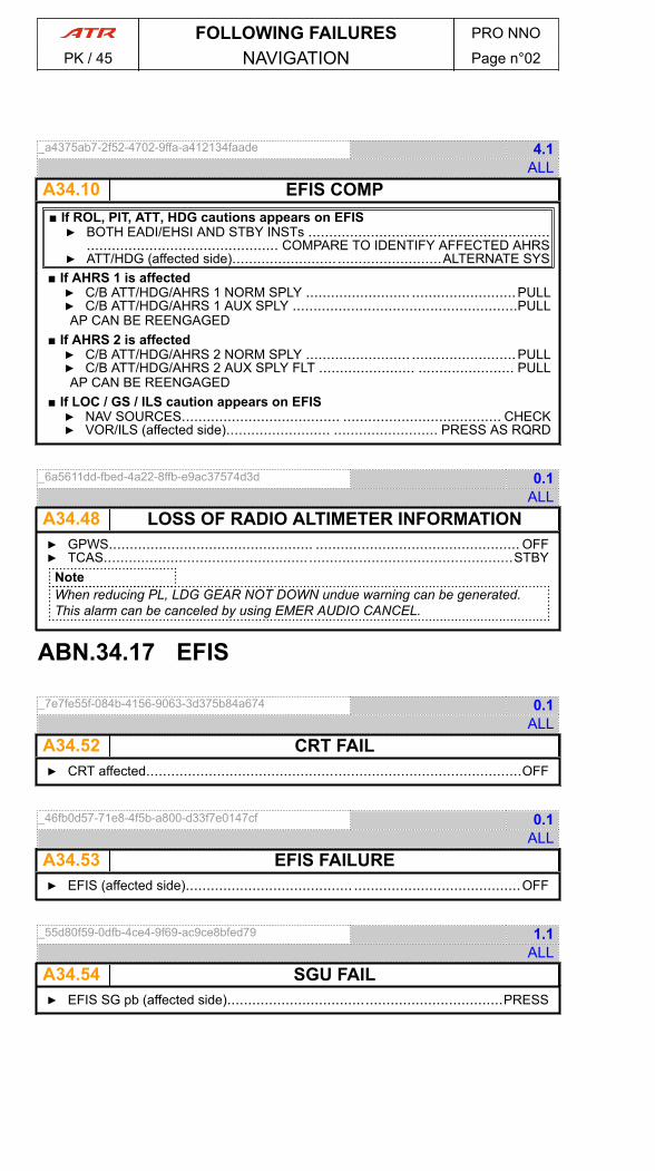
_a4375ab7-2f52-4702-9ffa-a412134faade 4.1ALL
A34.10 EFIS COMP■ If ROL, PIT, ATT, HDG cautions appears on EFIS▶ BOTH EADI/EHSI AND STBY INSTs ..........................................................
.............................................. COMPARE TO IDENTIFY AFFECTED AHRS▶ ATT/HDG (affected side)..................................................ALTERNATE SYS
■ If AHRS 1 is affected▶ C/B ATT/HDG/AHRS 1 NORM SPLY ......................... .........................PULL▶ C/B ATT/HDG/AHRS 1 AUX SPLY ......................................................PULLAP CAN BE REENGAGED
■ If AHRS 2 is affected▶ C/B ATT/HDG/AHRS 2 NORM SPLY ......................... .........................PULL▶ C/B ATT/HDG/AHRS 2 AUX SPLY FLT ....................... ....................... PULLAP CAN BE REENGAGED
■ If LOC / GS / ILS caution appears on EFIS▶ NAV SOURCES...................................... ...................................... CHECK▶ VOR/ILS (affected side)......................... ......................... PRESS AS RQRD
_6a5611dd-fbed-4a22-8ffb-e9ac37574d3d 0.1ALL
A34.48 LOSS OF RADIO ALTIMETER INFORMATION▶ GPWS................................................. ................................................. OFF▶ TCAS..................................................................................................STBY
NoteWhen reducing PL, LDG GEAR NOT DOWN undue warning can be generated.This alarm can be canceled by using EMER AUDIO CANCEL.
ABN.34.17 EFIS
_7e7fe55f-084b-4156-9063-3d375b84a674 0.1ALL
A34.52 CRT FAIL▶ CRT affected..........................................................................................OFF
_46fb0d57-71e8-4f5b-a800-d33f7e0147cf 0.1ALL
A34.53 EFIS FAILURE▶ EFIS (affected side)........................................ ........................................OFF
_55d80f59-0dfb-4ce4-9f69-ac9ce8bfed79 1.1ALL
A34.54 SGU FAIL▶ EFIS SG pb (affected side)..................................................................PRESS
FOLLOWING FAILURES PRO NNO
PK / 45 NAVIGATION Page n°02
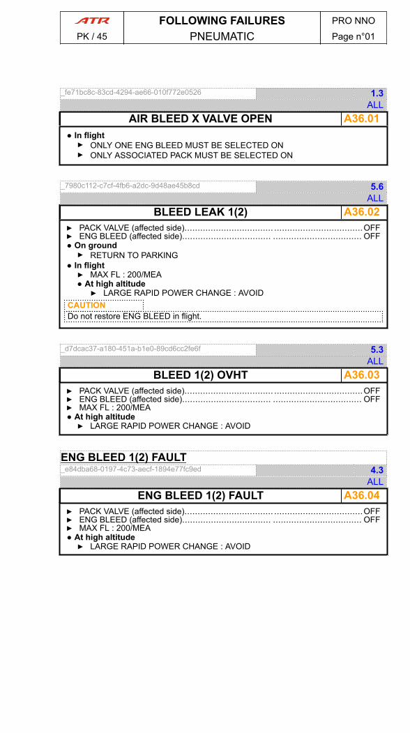
_fe71bc8c-83cd-4294-ae66-010f772e0526 1.3ALL
A36.01AIR BLEED X VALVE OPEN● In flight▶ ONLY ONE ENG BLEED MUST BE SELECTED ON▶ ONLY ASSOCIATED PACK MUST BE SELECTED ON
_7980c112-c7cf-4fb6-a2dc-9d48ae45b8cd 5.6ALL
A36.02BLEED LEAK 1(2)▶ PACK VALVE (affected side).................................. ..................................OFF▶ ENG BLEED (affected side).................................. .................................. OFF● On ground▶ RETURN TO PARKING
● In flight▶ MAX FL : 200/MEA● At high altitude▶ LARGE RAPID POWER CHANGE : AVOID
CAUTIONDo not restore ENG BLEED in flight.
_d7dcac37-a180-451a-b1e0-89cd6cc2fe6f 5.3ALL
A36.03BLEED 1(2) OVHT▶ PACK VALVE (affected side).................................. ..................................OFF▶ ENG BLEED (affected side).................................. .................................. OFF▶ MAX FL : 200/MEA● At high altitude▶ LARGE RAPID POWER CHANGE : AVOID
ENG BLEED 1(2) FAULT_e84dba68-0197-4c73-aecf-1894e77fc9ed 4.3
ALL A36.04ENG BLEED 1(2) FAULT
▶ PACK VALVE (affected side).................................. ..................................OFF▶ ENG BLEED (affected side).................................. .................................. OFF▶ MAX FL : 200/MEA● At high altitude▶ LARGE RAPID POWER CHANGE : AVOID
FOLLOWING FAILURES PRO NNO
PK / 45 PNEUMATIC Page n°01

PAGE
INTENTIONALLY
LEFT BLANK
FOLLOWING FAILURES PRO NNO
PK / 45 PNEUMATIC Page n°02
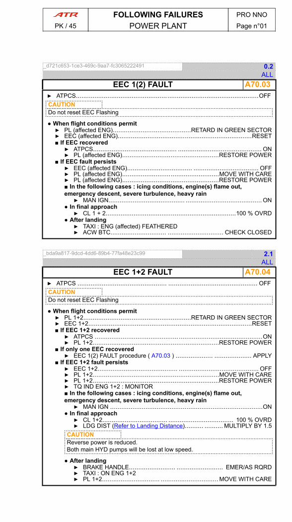
_d721c653-1ce3-469c-9aa7-fc3065222491 0.2ALL
A70.03EEC 1(2) FAULT▶ ATPCS..................................................................................................OFFCAUTIONDo not reset EEC Flashing
● When flight conditions permit▶ PL (affected ENG)..........................................RETARD IN GREEN SECTOR▶ EEC (affected ENG)........................................................................RESET■ If EEC recovered▶ ATPCS............................................. ............................................. ON▶ PL (affected ENG)....................................................RESTORE POWER
■ If EEC fault persists▶ EEC (affected ENG)................................... ................................... OFF▶ PL (affected ENG)....................................................MOVE WITH CARE▶ PL (affected ENG)....................................................RESTORE POWER■ In the following cases : icing conditions, engine(s) flame out,emergency descent, severe turbulence, heavy rain▶ MAN IGN......................................... ......................................... ON
● In final approach▶ CL 1 + 2......................................................................100 % OVRD
● After landing▶ TAXI : ENG (affected) FEATHERED▶ ACW BTC.............................. .............................. CHECK CLOSED
_bda9a817-9dcd-4dd6-89b4-77fa48e23c99 2.1ALL
A70.04EEC 1+2 FAULT▶ ATPCS ................................................ ................................................ OFFCAUTIONDo not reset EEC Flashing
● When flight conditions permit▶ PL 1+2..........................................................RETARD IN GREEN SECTOR▶ EEC 1+2........................................................................................RESET■ If EEC 1+2 recovered▶ ATPCS ..........................................................................................ON▶ PL 1+2....................................................................RESTORE POWER
■ If only one EEC recovered▶ EEC 1(2) FAULT procedure ( A70.03 ) .................... .................... APPLY
■ If EEC 1+2 fault persists▶ EEC 1+2........................................... ........................................... OFF▶ PL 1+2....................................................................MOVE WITH CARE▶ PL 1+2....................................................................RESTORE POWER▶ TQ IND ENG 1+2 : MONITOR■ In the following cases : icing conditions, engine(s) flame out,emergency descent, severe turbulence, heavy rain▶ MAN IGN ..................................................................................ON
● In final approach▶ CL 1+2................................... ................................... 100 % OVRD▶ LDG DIST (Refer to Landing Distance).......... .......... MULTIPLY BY 1.5
CAUTIONReverse power is reduced.Both main HYD pumps will be lost at low speed.
● After landing▶ BRAKE HANDLE......................... ......................... EMER/AS RQRD▶ TAXI : ON ENG 1+2▶ PL 1+2............................... ............................... MOVE WITH CARE
FOLLOWING FAILURES PRO NNO
PK / 45 POWER PLANT Page n°01

_a2f727b9-f20f-464c-b445-4da290f34f7d 3.1ALL
A70.05 PEC 1(2) FAULT■ If in short final approach (below 400 ft RA)▶ GO-AROUND..................................... ..................................... PERFORM
● Above 400 ft or when flight conditions permit▶ CL (affected ENG)................................ ................................ 100 % OVRD▶ PEC (affected ENG)........................................................................RESET■ If PEC recovered▶ CL(affected ENG)................................... ................................... AUTO
■ If PEC fault persists▶ PEC (affected ENG)................................... ................................... OFF▶ PL (affected ENG)....................................................MOVE WITH CARE● For landing▶ CL 1+2 ...................................................................... 100 % OVRD▶ PL : KEEP AT OR ABOVE FI UNTIL NOSE WHEEL ON GROUND▶ REVERSE (affected ENG) : DO NOT USE
● After landing▶ TAXI : ON ENG 1+2▶ ACW BTC .............................. ..............................CHECK CLOSED
_fad4caf4-f077-4d91-adb0-f0a64d09be50 1.3ALL
A70.06 PEC 1(2) SGL CH● In flight▶ PEC 1(2) : DO NOT RESET
● For landing▶ PEC 1(2) FAULT.................................. .................................. ANTICIPATE
_ed6c37d4-1713-47ed-9a05-503f67d19c63 0.5ALL
A70.07 ENG 1(2) FLAME OUT IN FLIGHT▶ PL (affected ENG).......................................... .......................................... FI■ If NH drops below 30 % (no immediate relight)▶ CL (affected ENG).......................... ..........................FTR THEN FUEL S.O.
■ If damage suspected▶ FIRE HANDLE (affected ENG)............................................................PULL▶ LAND ASAP▶ SINGLE ENG OPERATION procedure ( A70.12 ) ............... ............... APPLY
■ If no damage suspected▶ ENG RESTART IN FLIGHT procedure ( A70.09 ) ............... ............... APPLY■ If not successful▶ LAND ASAP▶ SINGLE ENG OPERATION procedure ( A70.12 ) ..........................APPLY
_7b708083-4d8a-403d-b314-aef3bb72ac08 1.1ALL
A70.08 ENG 1(2) FLAME OUT ON GROUND▶ PL 1+ 2.................................................................................................... GI▶ AIRCRAFT............................................. .............................................STOP▶ BRAKE HANDLE............................................................................PARKING▶ CL (affected ENG)........................................................ FTR THEN FUEL S.O.▶ FIRE HANDLE (affected ENG)................................................................PULL▶ FUEL PUMP (affected ENG)....................................................................OFF▶ RETURN TO PARKING
FOLLOWING FAILURES PRO NNO
PK / 45 POWER PLANT Page n°02
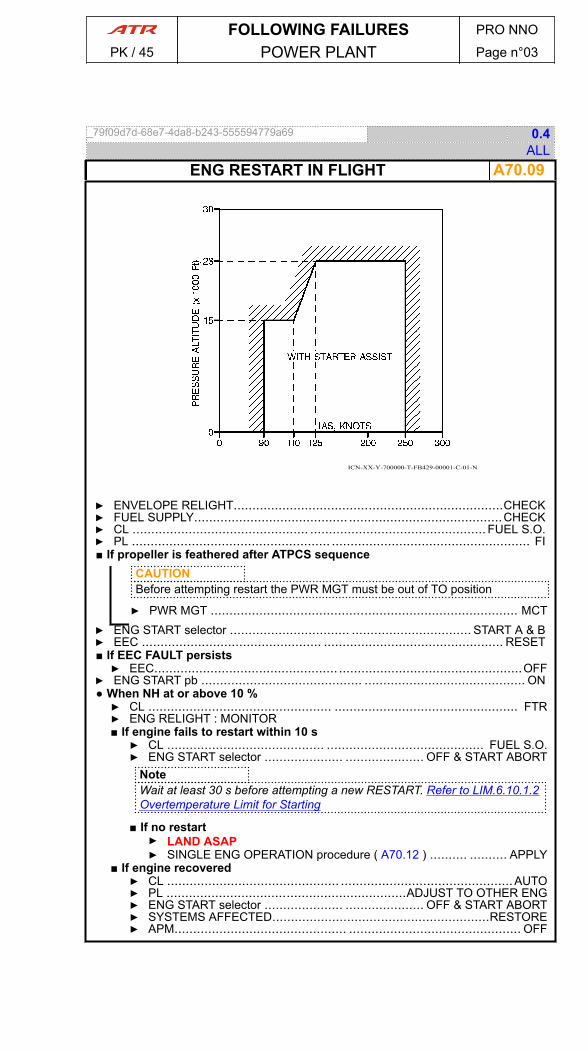
_79f09d7d-68e7-4da8-b243-555594779a69 0.4ALL
A70.09ENG RESTART IN FLIGHT
ICN-XX-Y-700000-T-FB429-00001-C-01-N
▶ ENVELOPE RELIGHT........................................................................CHECK▶ FUEL SUPPLY......................................... .........................................CHECK▶ CL ............................................... ............................................... FUEL S.O.▶ PL ..................................................... ..................................................... FI■ If propeller is feathered after ATPCS sequence
CAUTIONBefore attempting restart the PWR MGT must be out of TO position
▶ PWR MGT .................................................................................. MCT▶ ENG START selector ................................ ................................ START A & B▶ EEC ................................................ ................................................ RESET■ If EEC FAULT persists▶ EEC................................................. .................................................OFF
▶ ENG START pb ........................................... ........................................... ON● When NH at or above 10 %▶ CL ................................................. ................................................. FTR▶ ENG RELIGHT : MONITOR■ If engine fails to restart within 10 s▶ CL .......................................... .......................................... FUEL S.O.▶ ENG START selector ..................... ..................... OFF & START ABORT
NoteWait at least 30 s before attempting a new RESTART. Refer to LIM.6.10.1.2Overtemperature Limit for Starting
■ If no restart▶ LAND ASAP▶ SINGLE ENG OPERATION procedure ( A70.12 ) .......... .......... APPLY
■ If engine recovered▶ CL .............................................. ..............................................AUTO▶ PL ................................................................ADJUST TO OTHER ENG▶ ENG START selector ..................... ..................... OFF & START ABORT▶ SYSTEMS AFFECTED..........................................................RESTORE▶ APM.............................................. .............................................. OFF
FOLLOWING FAILURES PRO NNO
PK / 45 POWER PLANT Page n°03

_19220f29-eed8-48ed-b98b-243842710061 1.2ALL
A70.10 ENG STALL▶ PL (affected ENG).......................................... .......................................... FI▶ ENG PARAMETERS : MONITOR■ If abnormal engine parameters▶ CL (affected ENG).................................................... FTR THEN FUEL S.O.▶ LAND ASAP▶ SINGLE ENG OPERATION procedure ( A70.12 ) ............... ............... APPLY
■ If normal engine parameters▶ DE/ANTI ICING ENG ..................................... ..................................... ON▶ PL (affected ENG)........................................................SLOWLY ADVANCE■ If stall reoccurs▶ PL (affected ENG)................................................................................
.......................... RETARD AND OPERATE BELOW STALL THRESHOLD■ If stall does not reoccur▶ ENGINE OPERATION : RESUME
_67e24d55-a6c1-414a-b284-f214af47f119 1.1ALL
A70.11 LO PITCH IN FLIGHT▶ PL (affected ENG).......................................... .......................................... FI▶ CL (affected ENG)........................... ........................... FTR THEN FUEL S.O.▶ LAND ASAP▶ SINGLE ENG OPERATION procedure ( A70.12 ) ................. ................. APPLY
FOLLOWING FAILURES PRO NNO
PK / 45 POWER PLANT Page n°04
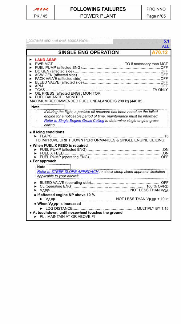
_29e7dd35-f992-4ef6-94b6-79003640c91e 5.1ALL
A70.12SINGLE ENG OPERATION▶ LAND ASAP▶ PWR MGT .............................. .............................. TO if necessary then MCT▶ FUEL PUMP (affected ENG)....................................................................OFF▶ DC GEN (affected side)..................................... ..................................... OFF▶ ACW GEN (affected side)........................................................................OFF▶ PACK VALVE (affected side).................................. ..................................OFF▶ BLEED VALVE (affected side)................................. .................................OFF▶ APM .................................................. .................................................. OFF▶ TCAS ............................................. ............................................. TA ONLY▶ OIL PRESS (affected ENG) : MONITOR▶ FUEL BALANCE : MONITORMAXIMUM RECOMMENDED FUEL UNBALANCE IS 200 kg (440 lb).Note
- If during the flight, a positive oil pressure has been noted on the failedengine for a noticeable period of time, maintenance must be informed.
- Refer to Single Engine Gross Ceiling to determine single engine grossceiling.
■ If icing conditions▶ FLAPS..................................................................................................15TO IMPROVE DRIFT DOWN PERFORMANCES & SINGLE ENGINE CEILING.
● When FUEL X FEED is required▶ FUEL PUMP (affected ENG)..................................................................ON▶ FUEL X FEED......................................................................................ON▶ FUEL PUMP (operating ENG)............................... ...............................OFF
● For approachNoteRefer to STEEP SLOPE APPROACH to check steep slope approach limitationapplicable to your aircraft.
▶ BLEED VALVE (operating side).............................. ..............................OFF▶ CL (operating ENG)............................... ............................... 100 % OVRD▶ VAPP .................................. .................................. NOT LESS THAN VGA■ If affected engine NP above 10 %▶ VAPP ......................... ......................... NOT LESS THAN VREF + 10 kt
● When VAPP is increased▶ LDG DISTANCE........................... ........................... MULTIPLY BY 1.15
● At touchdown, until nosewheel touches the ground▶ PL : MAINTAIN AT OR ABOVE FI
FOLLOWING FAILURES PRO NNO
PK / 45 POWER PLANT Page n°05
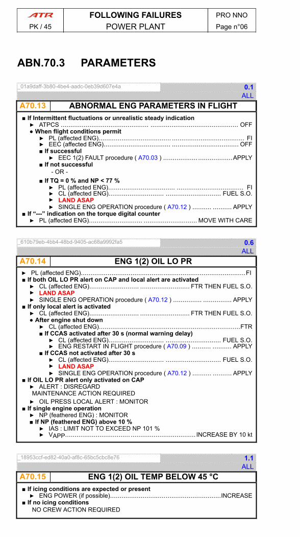
ABN.70.3 PARAMETERS
_01a9daff-3b80-4be4-aadc-0eb39d607e4a 0.1ALL
A70.13 ABNORMAL ENG PARAMETERS IN FLIGHT■ If Intermittent fluctuations or unrealistic steady indication▶ ATPCS .............................................. .............................................. OFF● When flight conditions permit▶ PL (affected ENG)...................................... ...................................... FI▶ EEC (affected ENG)................................... ................................... OFF■ If successful▶ EEC 1(2) FAULT procedure ( A70.03 ) .................. ..................APPLY
■ If not successful- OR -
■ If TQ = 0 % and NP < 77 %▶ PL (affected ENG)................................... ................................... FI▶ CL (affected ENG)............................. ............................. FUEL S.O.▶ LAND ASAP▶ SINGLE ENG OPERATION procedure ( A70.12 ) .......... .......... APPLY
■ If “---” indication on the torque digital counter▶ PL (affected ENG)............................ ............................ MOVE WITH CARE
_610b79eb-4bb4-48bd-9405-ac68a9992fa5 0.6ALL
A70.14 ENG 1(2) OIL LO PR▶ PL (affected ENG)......................................................................................FI■ If both OIL LO PR alert on CAP and local alert are activated▶ CL (affected ENG).......................... .......................... FTR THEN FUEL S.O.▶ LAND ASAP▶ SINGLE ENG OPERATION procedure ( A70.12 ) ............... ............... APPLY
■ If only local alert is activated▶ CL (affected ENG).......................... .......................... FTR THEN FUEL S.O.● After engine shut down▶ CL (affected ENG)..........................................................................FTR■ If CCAS activated after 30 s (normal warning delay)▶ CL (affected ENG)............................. ............................. FUEL S.O.▶ ENG RESTART IN FLIGHT procedure ( A70.09 ) .......... .......... APPLY
■ If CCAS not activated after 30 s▶ CL (affected ENG)............................. ............................. FUEL S.O.▶ LAND ASAP▶ SINGLE ENG OPERATION procedure ( A70.12 ) .......... .......... APPLY
■ If OIL LO PR alert only activated on CAP▶ ALERT : DISREGARDMAINTENANCE ACTION REQUIRED▶ OIL PRESS LOCAL ALERT : MONITOR
■ If single engine operation▶ NP (feathered ENG) : MONITOR■ If NP (feathered ENG) above 10 %▶ IAS : LIMIT NOT TO EXCEED NP 101 %▶ VAPP.................................. .................................. INCREASE BY 10 kt
_18953ccf-ed82-40a0-af8c-65bc5cbc8e76 1.1ALL
A70.15 ENG 1(2) OIL TEMP BELOW 45 °C■ If icing conditions are expected or present▶ ENG POWER (if possible)..........................................................INCREASE
■ If no icing conditionsNO CREW ACTION REQUIRED
FOLLOWING FAILURES PRO NNO
PK / 45 POWER PLANT Page n°06
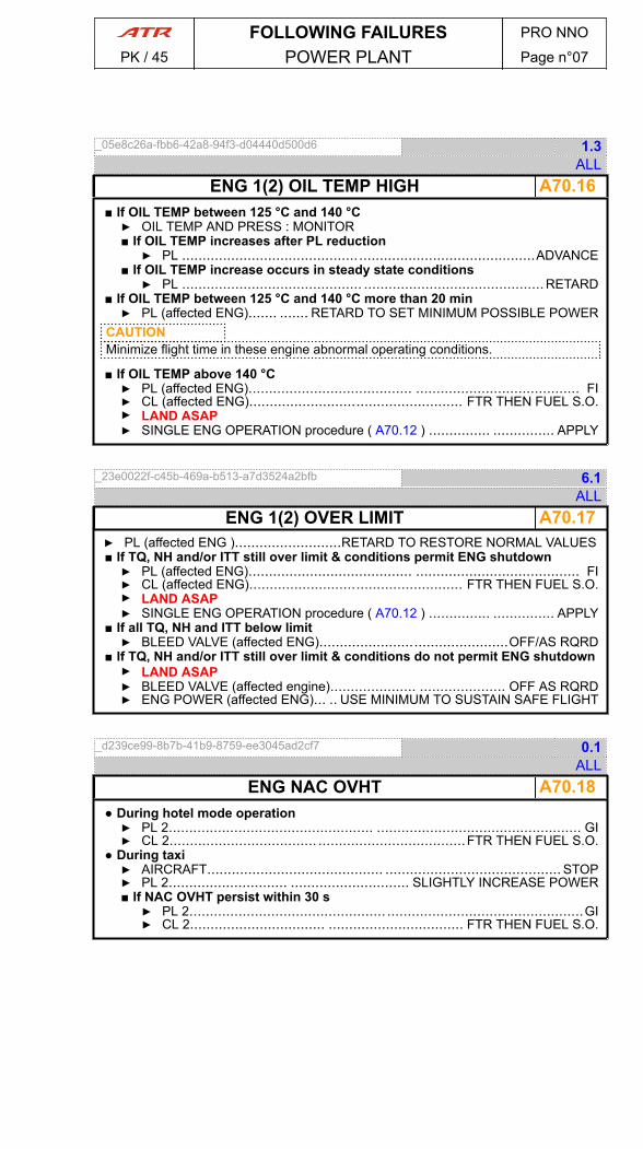
_05e8c26a-fbb6-42a8-94f3-d04440d500d6 1.3ALL
A70.16ENG 1(2) OIL TEMP HIGH■ If OIL TEMP between 125 °C and 140 °C▶ OIL TEMP AND PRESS : MONITOR■ If OIL TEMP increases after PL reduction▶ PL ......................................................................................ADVANCE
■ If OIL TEMP increase occurs in steady state conditions▶ PL ............................................ ............................................RETARD
■ If OIL TEMP between 125 °C and 140 °C more than 20 min▶ PL (affected ENG)....... ....... RETARD TO SET MINIMUM POSSIBLE POWER
CAUTIONMinimize flight time in these engine abnormal operating conditions.
■ If OIL TEMP above 140 °C▶ PL (affected ENG)........................................ ........................................ FI▶ CL (affected ENG).................................................... FTR THEN FUEL S.O.▶ LAND ASAP▶ SINGLE ENG OPERATION procedure ( A70.12 ) ............... ............... APPLY
_23e0022f-c45b-469a-b513-a7d3524a2bfb 6.1ALL
A70.17ENG 1(2) OVER LIMIT▶ PL (affected ENG )..........................RETARD TO RESTORE NORMAL VALUES■ If TQ, NH and/or ITT still over limit & conditions permit ENG shutdown▶ PL (affected ENG)........................................ ........................................ FI▶ CL (affected ENG).................................................... FTR THEN FUEL S.O.▶ LAND ASAP▶ SINGLE ENG OPERATION procedure ( A70.12 ) ............... ............... APPLY
■ If all TQ, NH and ITT below limit▶ BLEED VALVE (affected ENG)..............................................OFF/AS RQRD
■ If TQ, NH and/or ITT still over limit & conditions do not permit ENG shutdown▶ LAND ASAP▶ BLEED VALVE (affected engine)..................... ..................... OFF AS RQRD▶ ENG POWER (affected ENG)... .. USE MINIMUM TO SUSTAIN SAFE FLIGHT
_d239ce99-8b7b-41b9-8759-ee3045ad2cf7 0.1ALL
A70.18ENG NAC OVHT● During hotel mode operation▶ PL 2.................................................. .................................................. GI▶ CL 2.................................... ....................................FTR THEN FUEL S.O.
● During taxi▶ AIRCRAFT........................................... ........................................... STOP▶ PL 2............................. ............................. SLIGHTLY INCREASE POWER■ If NAC OVHT persist within 30 s▶ PL 2................................................ ................................................GI▶ CL 2................................. ................................. FTR THEN FUEL S.O.
FOLLOWING FAILURES PRO NNO
PK / 45 POWER PLANT Page n°07
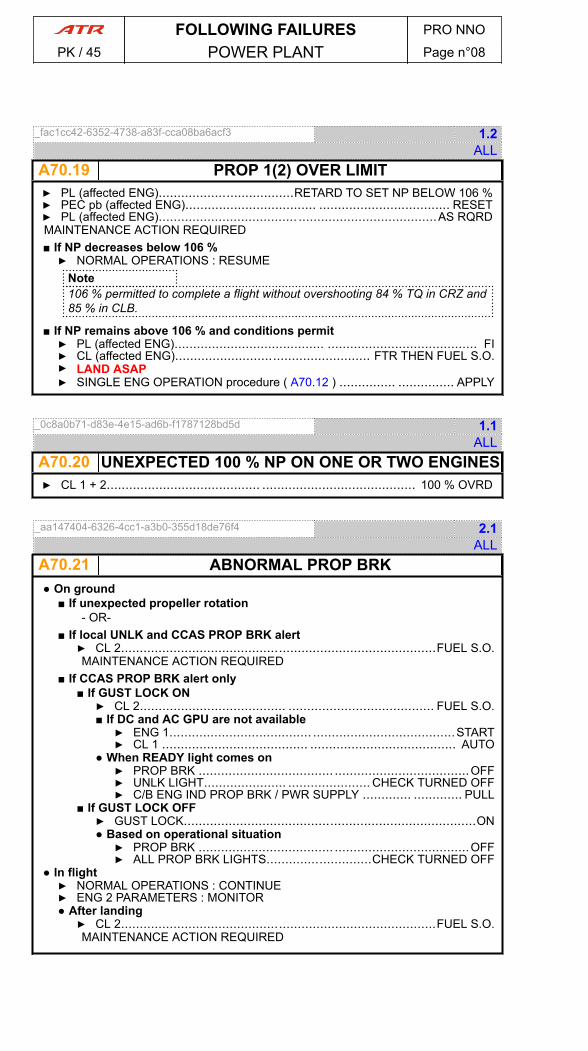
_fac1cc42-6352-4738-a83f-cca08ba6acf3 1.2ALL
A70.19 PROP 1(2) OVER LIMIT▶ PL (affected ENG)....................................RETARD TO SET NP BELOW 106 %▶ PEC pb (affected ENG)................................... ................................... RESET▶ PL (affected ENG)..................................... .....................................AS RQRDMAINTENANCE ACTION REQUIRED■ If NP decreases below 106 %▶ NORMAL OPERATIONS : RESUME
Note106 % permitted to complete a flight without overshooting 84 % TQ in CRZ and85 % in CLB.
■ If NP remains above 106 % and conditions permit▶ PL (affected ENG)........................................ ........................................ FI▶ CL (affected ENG).................................................... FTR THEN FUEL S.O.▶ LAND ASAP▶ SINGLE ENG OPERATION procedure ( A70.12 ) ............... ............... APPLY
_0c8a0b71-d83e-4e15-ad6b-f1787128bd5d 1.1ALL
A70.20 UNEXPECTED 100 % NP ON ONE OR TWO ENGINES▶ CL 1 + 2......................................... ......................................... 100 % OVRD
_aa147404-6326-4cc1-a3b0-355d18de76f4 2.1ALL
A70.21 ABNORMAL PROP BRK● On ground
■ If unexpected propeller rotation- OR-
■ If local UNLK and CCAS PROP BRK alert▶ CL 2....................................................................................FUEL S.O.MAINTENANCE ACTION REQUIRED
■ If CCAS PROP BRK alert only■ If GUST LOCK ON▶ CL 2....................................... ....................................... FUEL S.O.■ If DC and AC GPU are not available▶ ENG 1...................................... ......................................START▶ CL 1 ....................................... ....................................... AUTO
● When READY light comes on▶ PROP BRK .................................... ....................................OFF▶ UNLK LIGHT...................... ...................... CHECK TURNED OFF▶ C/B ENG IND PROP BRK / PWR SUPPLY ............. ............. PULL
■ If GUST LOCK OFF▶ GUST LOCK..............................................................................ON● Based on operational situation▶ PROP BRK .................................... ....................................OFF▶ ALL PROP BRK LIGHTS............................CHECK TURNED OFF
● In flight▶ NORMAL OPERATIONS : CONTINUE▶ ENG 2 PARAMETERS : MONITOR● After landing▶ CL 2....................................................................................FUEL S.O.MAINTENANCE ACTION REQUIRED
FOLLOWING FAILURES PRO NNO
PK / 45 POWER PLANT Page n°08

ABN.70.5 START
_5b28baaa-695d-4e89-a29a-43c2206f26ee 4.2ALL
A70.22ABNORMAL PARAMETERS DURING START■ If ITT tends to exceed 900 °C, or no ITT, or no NH▶ CL (affected ENG).................................. .................................. FUEL S.O.▶ ENG START selector ....................... ....................... OFF & START ABORT
■ If excessive ITT during start▶ EXCESSIVE ITT DURING START procedure ( A70.23 ) ......................APPLY
■ If no ITT during start▶ NO ITT DURING START procedure ( A70.24 ) ................. ................. APPLY
■ If no NH during start▶ NO NH DURING START procedure ( A70.25 ) ................. ................. APPLY
_35ac5a71-9762-4310-808c-06658f176cb4 1.1ALL
A70.23EXCESSIVE ITT DURING START● When NH below 30 %▶ ENG START selector......................................................................CRANK▶ ENG START pb ......................................... ......................................... ON● After 15 s▶ ENG START selector............................................OFF & START ABORT
■ If ITT exceeds 950 °CMaintenance action required
_a8b062c6-27ad-4297-9a60-56066e160433 1.1ALL
A70.24NO ITT DURING START● After 30 s to permit fuel draining▶ ENG START selector......................................................................CRANK▶ ENG START pb....................................................................................ON● After 15 s▶ ENG START selector............................................OFF & START ABORT
_a3bdefe2-84c2-4577-93cd-5d63a5a0429c 1.3ALL
A70.25NO NH DURING STARTNoteOn BAT only, OIL PRESS indicator is not available.
▶ ENG START selector .......................... .......................... START A or START B▶ ENG START pb ........................................... ........................................... ON● After 10 s
■ If OIL pressure increases▶ CL .............................................................................................. FTR▶ NORMAL ENG START : CONTINUENH INDICATION IS INOPERATIVE
■ If OIL pressure does not increase▶ ENG START selector ..................... ..................... OFF & START ABORTMAINTENANCE ACTION REQUIRED
FOLLOWING FAILURES PRO NNO
PK / 45 POWER PLANT Page n°09
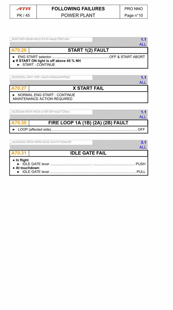
_6b9724f0-89a8-48c5-8124-9eab7f881a9c 1.1ALL
A70.26 START 1(2) FAULT▶ ENG START selector.......................... ..........................OFF & START ABORT■ If START ON light is off above 45 % NH▶ START : CONTINUE
_0d3583bc-2941-4f91-9a20-845e2e04f9a6 1.1ALL
A70.27 X START FAIL▶ NORMAL ENG START : CONTINUEMAINTENANCE ACTION REQUIRED
_0a3f20ab-f634-483d-a156-091eba772bec 1.1ALL
A70.30 FIRE LOOP 1A (1B) (2A) (2B) FAULT▶ LOOP (affected side)....................................... ....................................... OFF
_cac832dd-3603-4950-b032-2cd1012dee39 3.1ALL
A70.31 IDLE GATE FAIL● In flight▶ IDLE GATE lever ...................................... ...................................... PUSH
● At touchdown▶ IDLE GATE lever ..............................................................................PULL
FOLLOWING FAILURES PRO NNO
PK / 45 POWER PLANT Page n°10
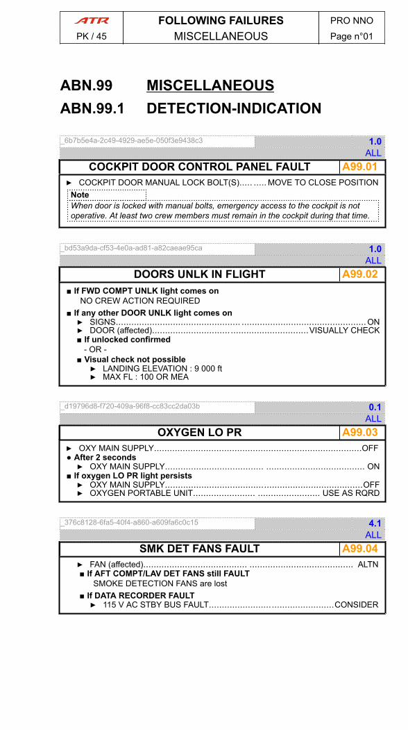
ABN.99 MISCELLANEOUSABN.99.1 DETECTION-INDICATION
_6b7b5e4a-2c49-4929-ae5e-050f3e9438c3 1.0ALL
A99.01COCKPIT DOOR CONTROL PANEL FAULT▶ COCKPIT DOOR MANUAL LOCK BOLT(S)..... ..... MOVE TO CLOSE POSITION
NoteWhen door is locked with manual bolts, emergency access to the cockpit is notoperative. At least two crew members must remain in the cockpit during that time.
_bd53a9da-cf53-4e0a-ad81-a82caeae95ca 1.0ALL
A99.02DOORS UNLK IN FLIGHT■ If FWD COMPT UNLK light comes on
NO CREW ACTION REQUIRED■ If any other DOOR UNLK light comes on▶ SIGNS................................................ ................................................ON▶ DOOR (affected)............................................................VISUALLY CHECK■ If unlocked confirmed
- OR -■ Visual check not possible▶ LANDING ELEVATION : 9 000 ft▶ MAX FL : 100 OR MEA
_d19796d8-f720-409a-96f8-cc83cc2da03b 0.1ALL
A99.03OXYGEN LO PR▶ OXY MAIN SUPPLY................................................................................OFF● After 2 seconds▶ OXY MAIN SUPPLY...................................... ...................................... ON
■ If oxygen LO PR light persists▶ OXY MAIN SUPPLY............................................................................OFF▶ OXYGEN PORTABLE UNIT........................ ........................ USE AS RQRD
_376c8128-6fa5-40f4-a860-a609fa6c0c15 4.1ALL
A99.04SMK DET FANS FAULT▶ FAN (affected)........................................ ........................................ ALTN■ If AFT COMPT/LAV DET FANS still FAULT
SMOKE DETECTION FANS are lost■ If DATA RECORDER FAULT▶ 115 V AC STBY BUS FAULT................................................CONSIDER
FOLLOWING FAILURES PRO NNO
PK / 45 MISCELLANEOUS Page n°01
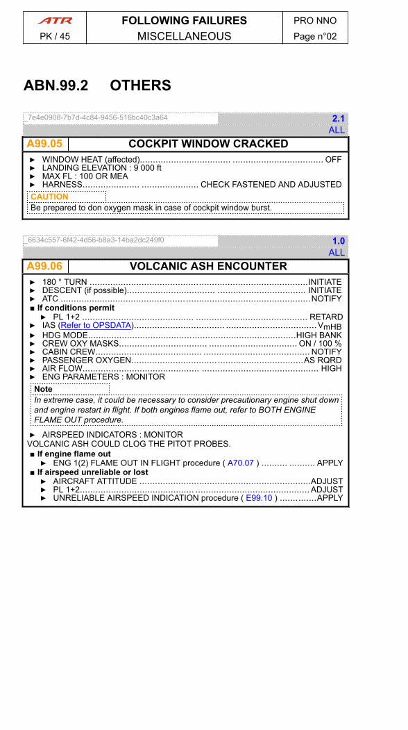
ABN.99.2 OTHERS
_7e4e0908-7b7d-4c84-9456-516bc40c3a64 2.1ALL
A99.05 COCKPIT WINDOW CRACKED▶ WINDOW HEAT (affected)................................... ................................... OFF▶ LANDING ELEVATION : 9 000 ft▶ MAX FL : 100 OR MEA▶ HARNESS...................... ...................... CHECK FASTENED AND ADJUSTEDCAUTIONBe prepared to don oxygen mask in case of cockpit window burst.
_6634c557-6f42-4d56-b8a3-14ba2dc249f0 1.0ALL
A99.06 VOLCANIC ASH ENCOUNTER▶ 180 ° TURN ....................................................................................INITIATE▶ DESCENT (if possible).................................. .................................. INITIATE▶ ATC ................................................................................................NOTIFY■ If conditions permit▶ PL 1+2 ........................................... ........................................... RETARD
▶ IAS (Refer to OPSDATA)................................... ...................................VmHB▶ HDG MODE................................................................................HIGH BANK▶ CREW OXY MASKS.................................. .................................. ON / 100 %▶ CABIN CREW......................................... ......................................... NOTIFY▶ PASSENGER OXYGEN..................................................................AS RQRD▶ AIR FLOW............................................. ............................................. HIGH▶ ENG PARAMETERS : MONITOR
NoteIn extreme case, it could be necessary to consider precautionary engine shut downand engine restart in flight. If both engines flame out, refer to BOTH ENGINEFLAME OUT procedure.
▶ AIRSPEED INDICATORS : MONITORVOLCANIC ASH COULD CLOG THE PITOT PROBES.■ If engine flame out▶ ENG 1(2) FLAME OUT IN FLIGHT procedure ( A70.07 ) .......... .......... APPLY
■ If airspeed unreliable or lost▶ AIRCRAFT ATTITUDE ..................................................................ADJUST▶ PL 1+2............................................ ............................................ ADJUST▶ UNRELIABLE AIRSPEED INDICATION procedure ( E99.10 ) ..............APPLY
FOLLOWING FAILURES PRO NNO
PK / 45 MISCELLANEOUS Page n°02
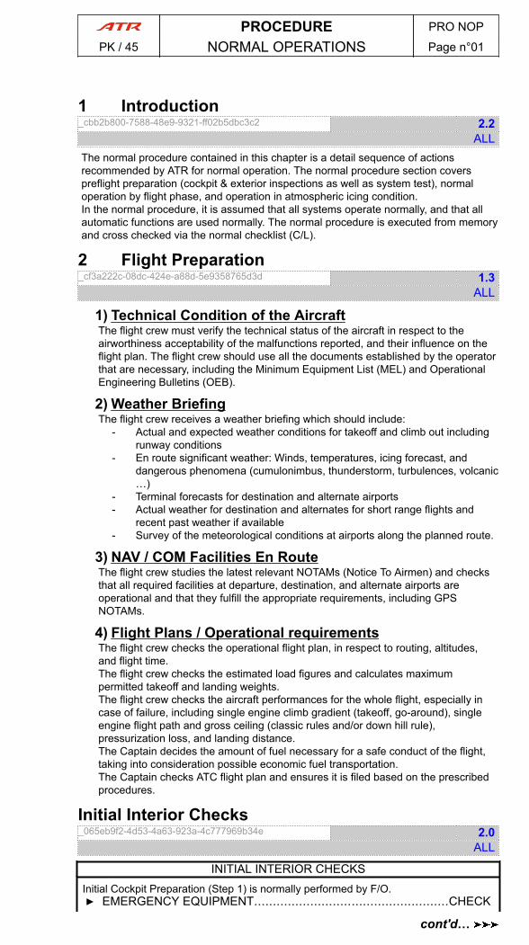
1 Introduction_cbb2b800-7588-48e9-9321-ff02b5dbc3c2 2.2
ALLThe normal procedure contained in this chapter is a detail sequence of actionsrecommended by ATR for normal operation. The normal procedure section coverspreflight preparation (cockpit & exterior inspections as well as system test), normaloperation by flight phase, and operation in atmospheric icing condition.In the normal procedure, it is assumed that all systems operate normally, and that allautomatic functions are used normally. The normal procedure is executed from memoryand cross checked via the normal checklist (C/L).
2 Flight Preparation_cf3a222c-08dc-424e-a88d-5e9358765d3d 1.3
ALL
1) Technical Condition of the AircraftThe flight crew must verify the technical status of the aircraft in respect to theairworthiness acceptability of the malfunctions reported, and their influence on theflight plan. The flight crew should use all the documents established by the operatorthat are necessary, including the Minimum Equipment List (MEL) and OperationalEngineering Bulletins (OEB).
2) Weather BriefingThe flight crew receives a weather briefing which should include:
- Actual and expected weather conditions for takeoff and climb out includingrunway conditions
- En route significant weather: Winds, temperatures, icing forecast, anddangerous phenomena (cumulonimbus, thunderstorm, turbulences, volcanic…)
- Terminal forecasts for destination and alternate airports- Actual weather for destination and alternates for short range flights and
recent past weather if available- Survey of the meteorological conditions at airports along the planned route.
3) NAV / COM Facilities En RouteThe flight crew studies the latest relevant NOTAMs (Notice To Airmen) and checksthat all required facilities at departure, destination, and alternate airports areoperational and that they fulfill the appropriate requirements, including GPSNOTAMs.
4) Flight Plans / Operational requirementsThe flight crew checks the operational flight plan, in respect to routing, altitudes,and flight time.The flight crew checks the estimated load figures and calculates maximumpermitted takeoff and landing weights.The flight crew checks the aircraft performances for the whole flight, especially incase of failure, including single engine climb gradient (takeoff, go-around), singleengine flight path and gross ceiling (classic rules and/or down hill rule),pressurization loss, and landing distance.The Captain decides the amount of fuel necessary for a safe conduct of the flight,taking into consideration possible economic fuel transportation.The Captain checks ATC flight plan and ensures it is filed based on the prescribedprocedures.
Initial Interior Checks_065eb9f2-4d53-4a63-923a-4c777969b34e 2.0
ALL
INITIAL INTERIOR CHECKSInitial Cockpit Preparation (Step 1) is normally performed by F/O.▶ EMERGENCY EQUIPMENT....................................................CHECK
PROCEDURE PRO NOP
PK / 45 NORMAL OPERATIONS Page n°01
cont'd…
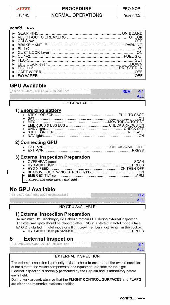
▶ GEAR PINS.................................. .................................. ON BOARD▶ ALL CIRCUITS BREAKERS.......................... ..........................CHECK▶ CDLS sw ......................................... ......................................... OFF▶ BRAKE HANDLE................................ ................................ PARKING▶ PL 1+2............................................ ............................................ GI▶ GUST LOCK lever ....................................................................... ON▶ CL 1+2...................................... ...................................... FUEL S.O.▶ FLAPS ......................................................................................SET▶ LDG GEAR lever ....................................................................DOWN▶ EEC 1+2................................... ................................... PRESSED IN▶ CAPT WIPER ...................................... ......................................OFF▶ F/O WIPER ....................................... ....................................... OFF
GPU Available_a2deb780-dacf-4e32-be8a-624a3e35672f REV 4.1
ALL
GPU AVAILABLE
1) Energizing Battery▶ STBY HORIZON............................................................PULL TO CAGE▶ BAT ............................................... ............................................... ON▶ MFC ..................................................................MONITOR AUTOTEST▶ EMER BUS & ESS BUS ................... ................... CHECK ARROWS ON▶ UNDV light.................................... .................................... CHECK OFF▶ STBY HORIZON....................................................................RELEASE▶ NAV lights........................................... ........................................... ON
2) Connecting GPU▶ EXT PWR .............................. ..............................CHECK AVAIL LIGHT▶ EXT PWR ........................................ ........................................ PRESS
3) External Inspection Preparation▶ OVERHEAD panel ................................... ...................................SCAN▶ HYD AUX PUMP........................................................................PRESS▶ HYD X FEED ................................ ................................ ON THEN OFF▶ BEACON, LOGO, WING, STROBE lights............................................ON▶ EMER EXIT LT sw .................................... ....................................ARMTo inspect the emergency exit light.
No GPU Available_631efd70-0aef-4d8d-ab24-eb598cca2883 0.2
ALL
NO GPU AVAILABLE
1) External Inspection PreparationTo minimize BAT discharge, BAT should remain OFF during external inspection.The external lights should be checked after ENG 2 is started in hotel mode. OnceENG 2 is started in hotel mode one flight crew member must remain in the cockpit.
▶ HYD AUX PUMP pb pedestal .......................... .......................... PRESS
5 External Inspection_31e87942-b92a-4451-b92f-10d034ce36e1 8.1
ALL
EXTERNAL INSPECTIONThe external inspection is primarily a visual check to ensure that the overall conditionof the aircraft, the visible components, and equipment are safe for the flight.External inspection is normally performed by the Captain and is mandatory beforeeach flight.During walk around, observe that the FLIGHT CONTROL SURFACES and FLAPSare clear and memorize surfaces position.
PROCEDURE PRO NOP
PK / 45 NORMAL OPERATIONS Page n°02
cont'd…
cont'd…

ICN-XX-Y-000000-T-FB429-00962-A-01-N
3
2 1
4
5 7
6
14
9
1011
8
12
13
- Fig. 1 : External Inspection Flow -
1) Main Left landing Gear and Fairing▶ PARKING BRAKE ACCU PRESSURE...... ......CHECK 1 600 psi MINIMUM▶ MAINTENANCE DOORS..........................................................CLOSED▶ GEAR DOORS..........................................................................CHECK▶ WHEELS & TIRES..........................................................CHECK STATE▶ BRAKE TEMPERATURE SENSORS..................... ..................... CHECK▶ BRAKE WEAR DETECTORS......................................................CHECK▶ LANDING GEAR STRUCTURE......................... ......................... CHECK▶ HYDRAULIC LINES................................. ................................. CHECK▶ WHEEL WELL..................................... ..................................... CHECK▶ UPLOCK.......................................... .......................................... OPEN▶ FREE FALL ASSISTER..............................................................CHECK▶ SAFETY PIN........................................................................REMOVED▶ BEACON lights..........................................................................CHECK▶ AIR CONDITIONING panel ........................... ...........................LOCKED▶ PACK RAM AIR INLET........................ ........................ CLOSE & CLEAR▶ LAND lights....................................................................CHECK STATE▶ TAT COVER.................................... .................................... REMOVED▶ TAT PROBE..............................................................................CHECK▶ MAGNETIC FUEL LEVEL................................. ................................. IN
2) Left Wing Trailing Edge▶ FLAPS RAIL SEAL.................................. ..................................CHECK▶ FLAPS..................................... ..................................... CHECK STATE▶ EXHAUST NOZZLE....................................................................CLEAR▶ FLAPS POSITION.................................. .................................. CHECK▶ AILERON & TAB........................................................................CHECK▶ STATIC DISCHARGERS.............................. ..............................CHECK▶ HORN..................................... ..................................... CHECK STATE
3) Left Wing Leading Edge▶ NAV & STROBE lights................................................................CHECK▶ WING DE ICING BOOTS........................ ........................ CHECK STATE▶ FUEL VENT NACA INLET............................. ............................. CLEAR▶ MAGNETIC FUEL LEVEL................................. ................................. IN
PROCEDURE PRO NOP
PK / 45 NORMAL OPERATIONS Page n°03
cont'd…
cont'd…
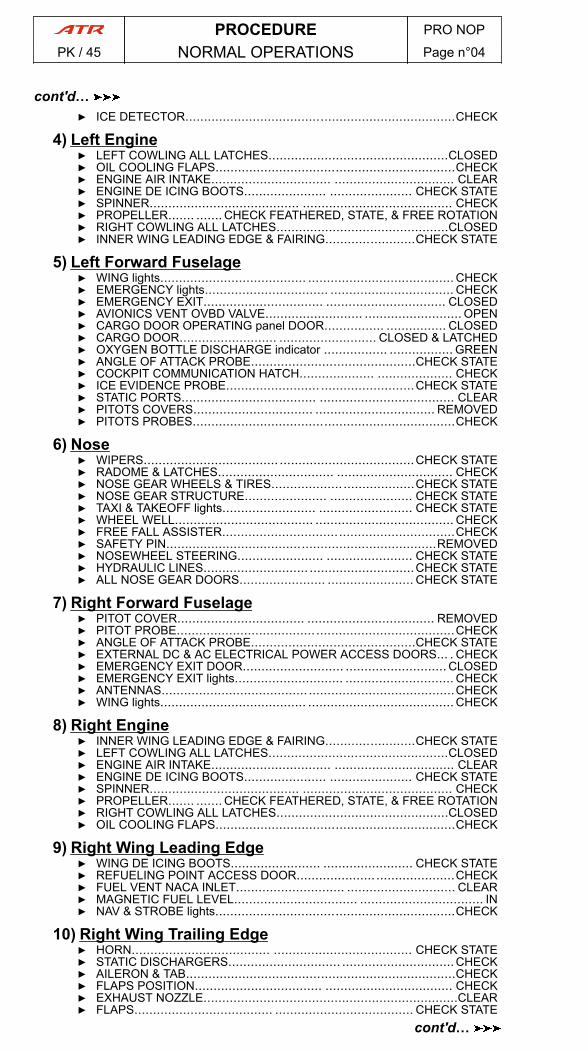
▶ ICE DETECTOR........................................................................CHECK
4) Left Engine▶ LEFT COWLING ALL LATCHES................................................CLOSED▶ OIL COOLING FLAPS................................................................CHECK▶ ENGINE AIR INTAKE................................ ................................ CLEAR▶ ENGINE DE ICING BOOTS...................... ...................... CHECK STATE▶ SPINNER........................................ ........................................ CHECK▶ PROPELLER....... ....... CHECK FEATHERED, STATE, & FREE ROTATION▶ RIGHT COWLING ALL LATCHES..............................................CLOSED▶ INNER WING LEADING EDGE & FAIRING........................CHECK STATE
5) Left Forward Fuselage▶ WING lights....................................... ....................................... CHECK▶ EMERGENCY lights................................. ................................. CHECK▶ EMERGENCY EXIT................................ ................................ CLOSED▶ AVIONICS VENT OVBD VALVE.......................... .......................... OPEN▶ CARGO DOOR OPERATING panel DOOR................ ................ CLOSED▶ CARGO DOOR.......................... .......................... CLOSED & LATCHED▶ OXYGEN BOTTLE DISCHARGE indicator ................. ................. GREEN▶ ANGLE OF ATTACK PROBE............................................CHECK STATE▶ COCKPIT COMMUNICATION HATCH.................... .................... CHECK▶ ICE EVIDENCE PROBE......................... .........................CHECK STATE▶ STATIC PORTS.................................... .................................... CLEAR▶ PITOTS COVERS................................ ................................ REMOVED▶ PITOTS PROBES......................................................................CHECK
6) Nose▶ WIPERS.................................... ....................................CHECK STATE▶ RADOME & LATCHES............................... ............................... CHECK▶ NOSE GEAR WHEELS & TIRES................... ...................CHECK STATE▶ NOSE GEAR STRUCTURE...................... ...................... CHECK STATE▶ TAXI & TAKEOFF lights......................... ......................... CHECK STATE▶ WHEEL WELL..................................... ..................................... CHECK▶ FREE FALL ASSISTER..............................................................CHECK▶ SAFETY PIN........................................................................REMOVED▶ NOSEWHEEL STEERING....................... ....................... CHECK STATE▶ HYDRAULIC LINES............................ ............................CHECK STATE▶ ALL NOSE GEAR DOORS....................... ....................... CHECK STATE
7) Right Forward Fuselage▶ PITOT COVER.................................. .................................. REMOVED▶ PITOT PROBE..................................... .....................................CHECK▶ ANGLE OF ATTACK PROBE............................................CHECK STATE▶ EXTERNAL DC & AC ELECTRICAL POWER ACCESS DOORS... . CHECK▶ EMERGENCY EXIT DOOR........................... ........................... CLOSED▶ EMERGENCY EXIT lights............................. ............................. CHECK▶ ANTENNAS....................................... .......................................CHECK▶ WING lights....................................... ....................................... CHECK
8) Right Engine▶ INNER WING LEADING EDGE & FAIRING........................CHECK STATE▶ LEFT COWLING ALL LATCHES................................................CLOSED▶ ENGINE AIR INTAKE................................ ................................ CLEAR▶ ENGINE DE ICING BOOTS...................... ...................... CHECK STATE▶ SPINNER........................................ ........................................ CHECK▶ PROPELLER....... ....... CHECK FEATHERED, STATE, & FREE ROTATION▶ RIGHT COWLING ALL LATCHES..............................................CLOSED▶ OIL COOLING FLAPS................................................................CHECK
9) Right Wing Leading Edge▶ WING DE ICING BOOTS........................ ........................ CHECK STATE▶ REFUELING POINT ACCESS DOOR..........................................CHECK▶ FUEL VENT NACA INLET............................. ............................. CLEAR▶ MAGNETIC FUEL LEVEL................................. ................................. IN▶ NAV & STROBE lights................................................................CHECK
10) Right Wing Trailing Edge▶ HORN..................................... ..................................... CHECK STATE▶ STATIC DISCHARGERS.............................. ..............................CHECK▶ AILERON & TAB........................................................................CHECK▶ FLAPS POSITION.................................. .................................. CHECK▶ EXHAUST NOZZLE....................................................................CLEAR▶ FLAPS..................................... ..................................... CHECK STATE
PROCEDURE PRO NOP
PK / 45 NORMAL OPERATIONS Page n°04
cont'd…
cont'd…

▶ FLAPS RAIL SEAL.................................. ..................................CHECK
11) Main Right Landing Gear and Fairing▶ MAGNETIC FUEL LEVEL................................. ................................. IN▶ TAT COVER.................................... .................................... REMOVED▶ TAT PROBE..............................................................................CHECK▶ LAND lights....................................................................CHECK STATE▶ AIR CONDITIONING GROUND CONNECTION.............. ..............CHECK▶ PACK RAM AIR INLET........................ ........................ CLOSE & CLEAR▶ AIR CONDITIONING panel ........................... ...........................LOCKED▶ REFUELING CONTROL panel ACCESS DOOR.......CLOSED & LATCHED▶ GEAR DOORS..........................................................................CHECK▶ LANDING GEAR STRUCTURE......................... ......................... CHECK▶ WHEEL WELL..................................... ..................................... CHECK▶ UPLOCK.......................................... .......................................... OPEN▶ FREE FALL ASSISTER..............................................................CHECK▶ SAFETY PIN........................................................................REMOVED▶ WHEELS & TIRES..........................................................CHECK STATE▶ BRAKE WEAR DETECTORS......................................................CHECK▶ BRAKE TEMPERATURE SENSORS..................... ..................... CHECK
12) Right Aft Fuselage▶ VHF ANTENNAS................................... ................................... CHECK▶ SERVICE DOOR................................... ................................... CHECK▶ OUTFLOW VALVES................................. ................................. CHECK▶ EMERGENCY LIGHT................................ ................................ CHECK
13) Tail▶ FLIGHT CONTROLS ACCESS DOOR................... ................... LOCKED▶ VOR ANTENNAS................................... ...................................CHECK▶ STABILIZER DE ICING BOOTS........................................CHECK STATE▶ LOGO lights..............................................................................CHECK▶ HORNS.................................... .................................... CHECK STATE▶ STABILIZER, ELEVATORS & TABS...................... ...................... CHECK▶ STATIC DISCHARGERS.............................. ..............................CHECK▶ FIN, RUDDER & TAB................................ ................................ CHECK▶ TAIL CONE, NAV & STROBE lights...................... ...................... CHECK▶ VORTEX GENERATORS............................................................CHECK
14) Left Aft Fuselage▶ WATER SERVICE panel ACCESS DOOR................. .................CLOSED▶ TOILET SERVICE panel ACCESS DOOR................. .................CLOSED▶ CABIN DOOR..................................... ..................................... CHECK▶ ENTRY EMERGENCY light............................ ............................ CHECK
Cockpit Preparation (Step 2)_90ef7fd6-cc36-4a4b-9cc8-17c134341c3a 4.1
ALL
COCKPIT PREPARATION (STEP 2)The Cockpit Preparation (Step 2) requires DC power. When supplied by BAT only,ENG 2 must be started in hotel mode for DC power supply.Before starting ENG 2 the flight crew should consider conducting refueling and aircraftaft loading.No GPU available-Start ENG 2 in hotel mode▶ STICK PUSHER/SHAKER..........................................................TESTRefer to AFM - Stick Pusher-Shaker Test
▶ FUEL PUMP & FUEL X FEED ......................... ......................... TESTRefer to PRO.NOP.NOR.30.1 Fuel Pump and X Feed Tests
▶ ENG 2 FIRE...................................... ...................................... TESTRefer to PRO.SYSTEM TEST.29.1 Engine Fire Protection
▶ ENG 2............................. .............................START in HOTEL MODERefer to PRO.NOP.NOR.10 Hotel Mode Start Up
▶ DC GEN 2 FAULT light......................... .........................TURNED OFF▶ ANN LT....................................................................................TEST
PROCEDURE PRO NOP
PK / 45 NORMAL OPERATIONS Page n°05
cont'd…

Overhead Panel_b7685057-a21b-48ab-be6a-b2e34edeea36 REV 2.5
ALL
OVERHEAD PANEL▶ DOME lights................................... ................................... AS RQRD▶ STBY COMPASS light..................................................CHECK & OFF▶ STORM lights..............................................................CHECK & OFF▶ CALLS ATTND ......................................................................CHECK▶ MIN CAB LT ....................................... .......................................OFF▶ FUEL PUMP & FUEL X FEED ......................... ......................... TEST▶ DOORS......................................... ......................................... TEST▶ SPLR lights......................................................CHECK TURNED OFF▶ TLU sw .............................................................. AUTO & GUARDED▶ FLT CTL FAULT light.................... .................... CHECK TURNED OFF▶ LDG GEAR overhead panel lights...................... ......................CHECK▶ MFC .................................. ..................................CHECK NO LIGHT▶ ENG 1 FIRE panel ....................................................................TEST▶ EXTERNAL lights................................................................AS RQRD▶ PROP BRAKE...................................................................ENGAGED▶ ENG START selector ........................................OFF & START ABORT▶ MAIN ELEC PWR panel ............................ ............................ CHECK▶ CVR ........................................................................................TEST▶ SIGNS............................................ ............................................ ON▶ EMER EXIT LT ..........................................................................ARM▶ DISARM light......................... ......................... CHECK TURNED OFF▶ DE/ANTI ICING lights........................................CHECK TURNED OFF▶ PROBES HTG ..................................... ..................................... OFF▶ WINDSHIELD HTG pb ..................................................................ON▶ AC WILD ELEC PWR panel ....................................................CHECK▶ HYD PWR panel ................................. ................................. CHECK▶ EMER LOC XMTR panel .................... .................... AUTO/NO LIGHT▶ ANN LT ...................................... ...................................... AS RQRD▶ AIR BLEED panel & COMPT TEMP panel ................................CHECK▶ RECIRC FAN 1+2 ........................................................................ON▶ OVBD VALVE .......................... .......................... AUTO & GUARDED▶ OXYGEN panel .................................. .................................. CHECK▶ COMPT SMK panel ................................. .................................TEST▶ ENG 2 FIRE panel ....................................................................TEST
Pedestal and Central Panels_beb157ad-4b21-479f-b639-9e264a95edd5 REV 8.1
ALL
PEDESTAL AND CENTRAL PANELS▶ ATPCS STATIC TEST........................................................PERFORM▶ TCAS ........................................................................ TEST & AUTO▶ LT INST/DSPL/PNL ............................................................AS RQRD▶ ACARS (if installed) ............................... ............................... CHECK▶ FDEP (if installed) ........................... ........................... SET & CHECK▶ HF (if installed) ......................................................................CHECK▶ TRIMS.......................................... .......................................... TEST▶ VHF ....................................... ....................................... ON & TEST▶ ADF .................................... .................................... ADF POSITION▶ XPDR sw..................................... ..................................... AS RQRDSystem 1 on odd days and system 2 on even days.
▶ XPDR .......................................... .......................................... TEST▶ IDLE GATE lever ................................. ................................. CHECK▶ EMER AUDIO CANCEL.......................... .......................... GUARDED▶ GUST LOCK lever ................................... ................................... ON▶ FLAPS............................................. .............................................0°▶ AIL LOCK light........................ ........................ CHECH TURNED OFF
PROCEDURE PRO NOP
PK / 45 NORMAL OPERATIONS Page n°06
cont'd…
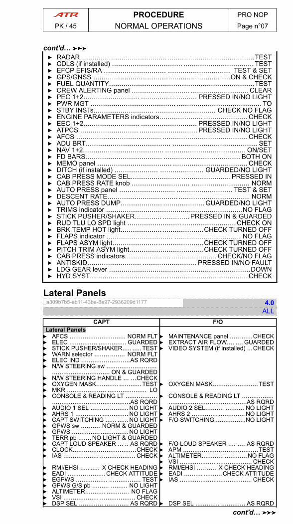
▶ RADAR....................................................................................TEST▶ CDLS (if installed) .................................. .................................. TEST▶ EFCP EFIS/RA .............................. .............................. TEST & SET▶ GPS/GNSS ..................................................................ON & CHECK▶ FUEL QUANTITY......................................................................TEST▶ CREW ALERTING panel ............................ ............................ CLEAR▶ PEC 1+2........................... ........................... PRESSED IN/NO LIGHT▶ PWR MGT ......................................... ......................................... TO▶ STBY INSTs............................. ............................. CHECK NO FLAG▶ ENGINE PARAMETERS indicators..................... ..................... CHECK▶ EEC 1+2........................... ........................... PRESSED IN/NO LIGHT▶ ATPCS ............................ ............................ PRESSED IN/NO LIGHT▶ AFCS ......................................... ......................................... CHECK▶ ADU BRT......................................... ......................................... SET▶ NAV 1+2....................................... ....................................... ON/SET▶ FD BARS..................................... ..................................... BOTH ON▶ MEMO panel .................................... .................................... CHECK▶ DITCH (if installed) ..................... ..................... GUARDED/NO LIGHT▶ CAB PRESS MODE SEL........................ ........................PRESSED IN▶ CAB PRESS RATE knob ............................ ............................ NORM▶ AUTO PRESS panel ........................... ........................... TEST & SET▶ DESCENT RATE.................................. .................................. NORM▶ AUTO PRESS DUMP.................... .................... GUARDED/NO LIGHT▶ TRIMS indicator ..................................................................NO FLAG▶ STICK PUSHER/SHAKER............. .............PRESSED IN & GUARDED▶ RUD TLU LO SPD light .......................... ..........................CHECK ON▶ BRK TEMP HOT light........................................CHECK TURNED OFF▶ FLAPS indicator ................................ ................................ NO FLAG▶ FLAPS ASYM light............................................CHECK TURNED OFF▶ PITCH TRIM ASYM light....................................CHECK TURNED OFF▶ CAB PRESS indicators...................... ......................CHECK/NO FLAG▶ ANTISKID.......................... .......................... PRESSED IN/NO FAULT▶ LDG GEAR lever ....................................................................DOWN▶ HYD SYST...................................... ......................................CHECK
Lateral Panels_a309b7b5-eb11-43be-8e97-2936209d1177 4.0
ALLCAPT F/O
Lateral Panels▶ AFCS .............................. NORM FLT▶ ELEC ............... ............... GUARDED▶ STICK PUSHER/SHAKER..... .....TEST
▶ MAINTENANCE panel ............CHECK▶ EXTRACT AIR FLOW.... .... GUARDED▶ VIDEO SYSTEM (if installed) ...CHECK
▶ WARN selector ........ ........ NORM FLT▶ ELEC IND ..........................AS RQRD▶ N/W STEERING sw ...........................
............................... ON & GUARDED▶ N/W STEERING HANDLE ... ...CHECK▶ OXYGEN MASK............ ............TEST ▶ OXYGEN MASK............ ............TEST▶ MKR ..................... ..................... LO▶ CONSOLE & READING LT .................
..........................................AS RQRD▶ CONSOLE & READING LT .................
..........................................AS RQRD▶ AUDIO 1 SEL .......... ..........NO LIGHT ▶ AUDIO 2 SEL.......... .......... NO LIGHT▶ AHRS 1 .............. .............. NO LIGHT ▶ AHRS 2 .............. .............. NO LIGHT▶ CAPT SWITCHING ...... ......NO LIGHT ▶ F/O SWITCHING ................NO LIGHT▶ GPWS sw .......... NORM & GUARDED▶ GPWS ............... ...............NO LIGHT▶ TERR pb ....... NO LIGHT & GUARDED▶ CAPT LOUD SPEAKER ... .. AS RQRD ▶ F/O LOUD SPEAKER .... .... AS RQRD▶ CLOCK..................................CHECK ▶ APM ........................................TEST▶ IAS ................... ................... CHECK ▶ ALTIMETER............ ............NO FLAG
▶ VSI ................... ................... CHECK▶ RMI/EHSI ..... ..... X CHECK HEADING ▶ RMI/EHSI ..... ..... X CHECK HEADING▶ EADI .......... ..........CHECK ATTITUDE ▶ EADI .......... ..........CHECK ATTITUDE▶ EGPWS ................. ................. TEST ▶ IAS ................... ................... CHECK▶ GPWS G/S pb ......... ......... NO LIGHT▶ ALTIMETER........... ........... . NO FLAG▶ VSI ................... ................... CHECK▶ DSP SEL ............. ............. AS RQRD ▶ DSP SEL ............. ............. AS RQRD
PROCEDURE PRO NOP
PK / 45 NORMAL OPERATIONS Page n°07
cont'd…
cont'd…
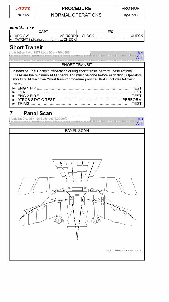
CAPT F/O▶ ADC-SW ............................AS RQRD ▶ CLOCK..................................CHECK▶ TAT/SAT indicator ......... ......... CHECK
Short Transit_a3c1e5cc-4a6d-4877-bbbb-90b44796a595 8.1
ALL
SHORT TRANSITInstead of Final Cockpit Preparation during short transit, perform these actions.These are the minimum AFM checks and must be done before each flight. Operatorsshould build their own “Short transit” procedure provided that it includes followingitems.▶ ENG 1 FIRE...................................... ...................................... TEST▶ CVR ........................................................................................TEST▶ ENG 2 FIRE...................................... ...................................... TEST▶ ATPCS STATIC TEST........................................................PERFORM▶ TRIMS.......................................... .......................................... TEST
7 Panel Scan_dafe3ad0-cda6-4458-8b5e-e604b356fef0 0.3
ALL
PANEL SCAN
ICN-XX-Y-000000-T-FB429-00963-A-01-N
1 2 3 4
5
6 7
PROCEDURE PRO NOP
PK / 45 NORMAL OPERATIONS Page n°08
cont'd…
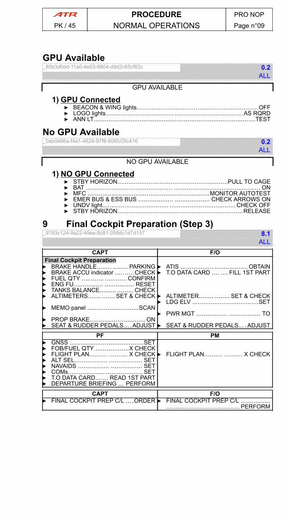
GPU Available_80b3d0dd-11a0-4e03-9804-d9d2c65cf82c 0.2
ALL
GPU AVAILABLE
1) GPU Connected▶ BEACON & WING lights..................................................................OFF▶ LOGO lights..................................... ..................................... AS RQRD▶ ANN LT........................................................................................TEST
No GPU Available_0ab0e66a-f4a1-4624-97f8-606fcf3fc416 0.2
ALL
NO GPU AVAILABLE
1) NO GPU Connected▶ STBY HORIZON............................................................PULL TO CAGE▶ BAT ............................................... ............................................... ON▶ MFC ..................................................................MONITOR AUTOTEST▶ EMER BUS & ESS BUS ................... ................... CHECK ARROWS ON▶ UNDV light.................................... .................................... CHECK OFF▶ STBY HORIZON....................................................................RELEASE
9 Final Cockpit Preparation (Step 3)_9793c124-9a22-49ee-8c81-059dc1d7d157 8.1
ALLCAPT F/O
Final Cockpit Preparation▶ BRAKE HANDLE........ ........ PARKING ▶ ATIS .................. .................. OBTAIN▶ BRAKE ACCU indicator ..... .....CHECK ▶ T.O DATA CARD .... .... FILL 1ST PART▶ FUEL QTY ............ ............ CONFIRM▶ ENG FU................ ................ RESET▶ TANKS BALANCE......... ......... CHECK▶ ALTIMETERS....... ....... SET & CHECK ▶ ALTIMETER........ ........ SET & CHECK
▶ LDG ELV ....................................SET▶ MEMO panel ............................SCAN
▶ PWR MGT ................. ................. TO▶ PROP BRAKE............... ............... ON▶ SEAT & RUDDER PEDALS... .ADJUST ▶ SEAT & RUDDER PEDALS... .ADJUST
PF PM▶ GNSS ........................................SET▶ FOB/FUEL QTY ..................X CHECK▶ FLIGHT PLAN.......... .......... X CHECK ▶ FLIGHT PLAN.......... .......... X CHECK▶ ALT SEL.................. .................. SET▶ NAVAIDS ................. ................. SET▶ COMs.................... .................... SET▶ T.O DATA CARD....... READ 1ST PART▶ DEPARTURE BRIEFING ... PERFORM
CAPT F/O▶ FINAL COCKPIT PREP C/L ... .ORDER ▶ FINAL COCKPIT PREP C/L ................
........................................ PERFORM
PROCEDURE PRO NOP
PK / 45 NORMAL OPERATIONS Page n°09
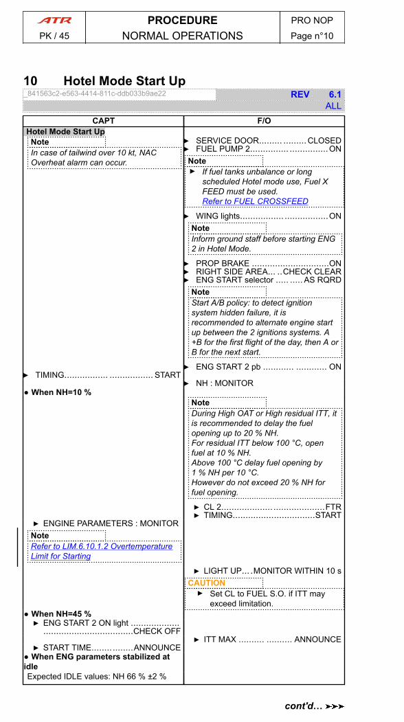
10 Hotel Mode Start Up_841563c2-e563-4414-811c-ddb033b9ae22 REV 6.1
ALLCAPT F/O
Hotel Mode Start UpNoteIn case of tailwind over 10 kt, NACOverheat alarm can occur.
▶ SERVICE DOOR......... .........CLOSED▶ FUEL PUMP 2............... ...............ON
Note▶ If fuel tanks unbalance or long
scheduled Hotel mode use, Fuel XFEED must be used.Refer to FUEL CROSSFEED
▶ WING lights................. .................ONNoteInform ground staff before starting ENG2 in Hotel Mode.
▶ PROP BRAKE ..............................ON▶ RIGHT SIDE AREA... ..CHECK CLEAR▶ ENG START selector ..... ..... AS RQRD
NoteStart A/B policy: to detect ignitionsystem hidden failure, it isrecommended to alternate engine startup between the 2 ignitions systems. A+B for the first flight of the day, then A orB for the next start.
▶ ENG START 2 pb ............ ............ ON▶ TIMING................. ................. START
▶ NH : MONITOR● When NH=10 %
NoteDuring High OAT or High residual ITT, itis recommended to delay the fuelopening up to 20 % NH.For residual ITT below 100 °C, openfuel at 10 % NH.Above 100 °C delay fuel opening by1 % NH per 10 °C.However do not exceed 20 % NH forfuel opening.
▶ CL 2........................................FTR▶ TIMING................................START
▶ ENGINE PARAMETERS : MONITORNoteRefer to LIM.6.10.1.2 OvertemperatureLimit for Starting
▶ LIGHT UP... .MONITOR WITHIN 10 sCAUTION▶ Set CL to FUEL S.O. if ITT may
exceed limitation.● When NH=45 %▶ ENG START 2 ON light ...................
...................................CHECK OFF▶ ITT MAX .......... .......... ANNOUNCE
▶ START TIME................ANNOUNCE● When ENG parameters stabilized atidleExpected IDLE values: NH 66 % ±2 %
PROCEDURE PRO NOP
PK / 45 NORMAL OPERATIONS Page n°10
cont'd…
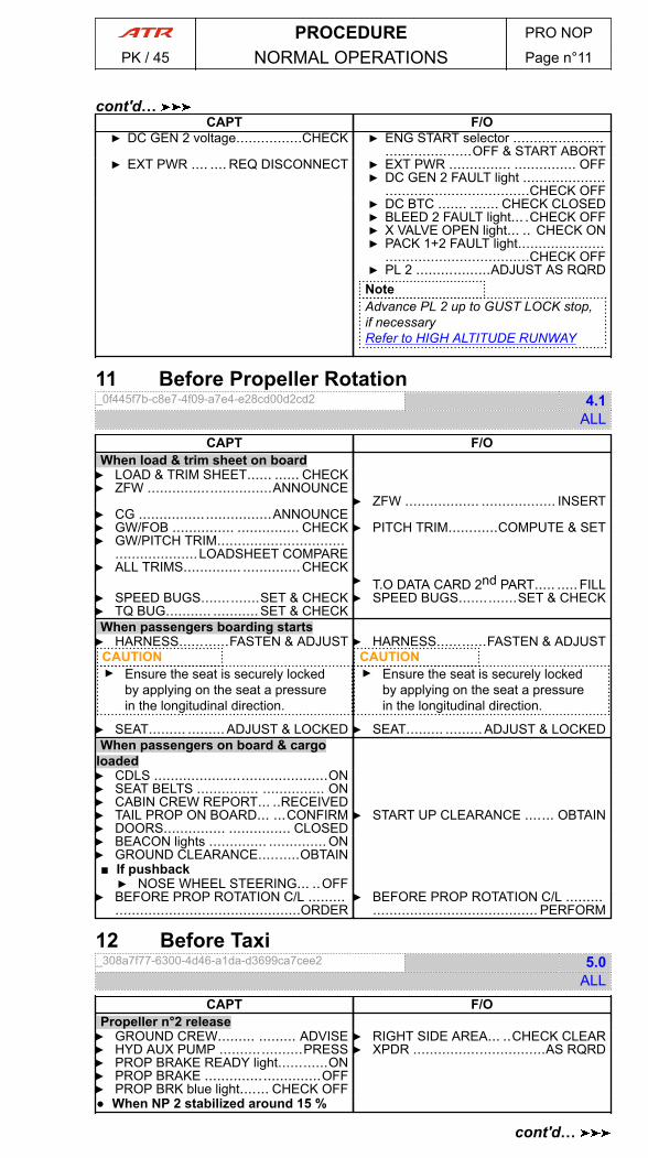
CAPT F/O▶ DC GEN 2 voltage................CHECK ▶ ENG START selector ......................
.....................OFF & START ABORT▶ EXT PWR .... .... REQ DISCONNECT ▶ EXT PWR ............... ............... OFF
▶ DC GEN 2 FAULT light .......................................................CHECK OFF
▶ DC BTC ....... ....... CHECK CLOSED▶ BLEED 2 FAULT light... .CHECK OFF▶ X VALVE OPEN light... .. CHECK ON▶ PACK 1+2 FAULT light.....................
...................................CHECK OFF▶ PL 2 ..................ADJUST AS RQRDNoteAdvance PL 2 up to GUST LOCK stop,if necessaryRefer to HIGH ALTITUDE RUNWAY
11 Before Propeller Rotation_0f445f7b-c8e7-4f09-a7e4-e28cd00d2cd2 4.1
ALLCAPT F/O
When load & trim sheet on board▶ LOAD & TRIM SHEET...... ...... CHECK▶ ZFW ..............................ANNOUNCE
▶ ZFW .................. .................. INSERT▶ CG ................................ANNOUNCE▶ GW/FOB ............... ............... CHECK ▶ PITCH TRIM............COMPUTE & SET▶ GW/PITCH TRIM...............................
....................LOADSHEET COMPARE▶ ALL TRIMS.............. ..............CHECK
▶ T.O DATA CARD 2nd PART..... ..... FILL▶ SPEED BUGS..............SET & CHECK ▶ SPEED BUGS..............SET & CHECK▶ TQ BUG........... ........... SET & CHECKWhen passengers boarding starts▶ HARNESS............FASTEN & ADJUST ▶ HARNESS............FASTEN & ADJUST
CAUTION▶ Ensure the seat is securely locked
by applying on the seat a pressurein the longitudinal direction.
▶ SEAT......... .........ADJUST & LOCKED
CAUTION▶ Ensure the seat is securely locked
by applying on the seat a pressurein the longitudinal direction.
▶ SEAT......... .........ADJUST & LOCKEDWhen passengers on board & cargo
loaded▶ CDLS ..........................................ON▶ SEAT BELTS ............... ............... ON▶ CABIN CREW REPORT... ..RECEIVED▶ TAIL PROP ON BOARD... ...CONFIRM▶ DOORS............... ............... CLOSED
▶ START UP CLEARANCE ....... OBTAIN
▶ BEACON lights .............. .............. ON▶ GROUND CLEARANCE..........OBTAIN■ If pushback▶ NOSE WHEEL STEERING... ..OFF
▶ BEFORE PROP ROTATION C/L ......................................................ORDER
▶ BEFORE PROP ROTATION C/L ................................................. PERFORM
12 Before Taxi_308a7f77-6300-4d46-a1da-d3699ca7cee2 5.0
ALLCAPT F/O
Propeller n°2 release▶ GROUND CREW......... ......... ADVISE ▶ RIGHT SIDE AREA... ..CHECK CLEAR▶ HYD AUX PUMP ....................PRESS ▶ XPDR ................................AS RQRD▶ PROP BRAKE READY light............ON▶ PROP BRAKE ............................OFF▶ PROP BRK blue light....... CHECK OFF● When NP 2 stabilized around 15 %
PROCEDURE PRO NOP
PK / 45 NORMAL OPERATIONS Page n°11
cont'd…
cont'd…
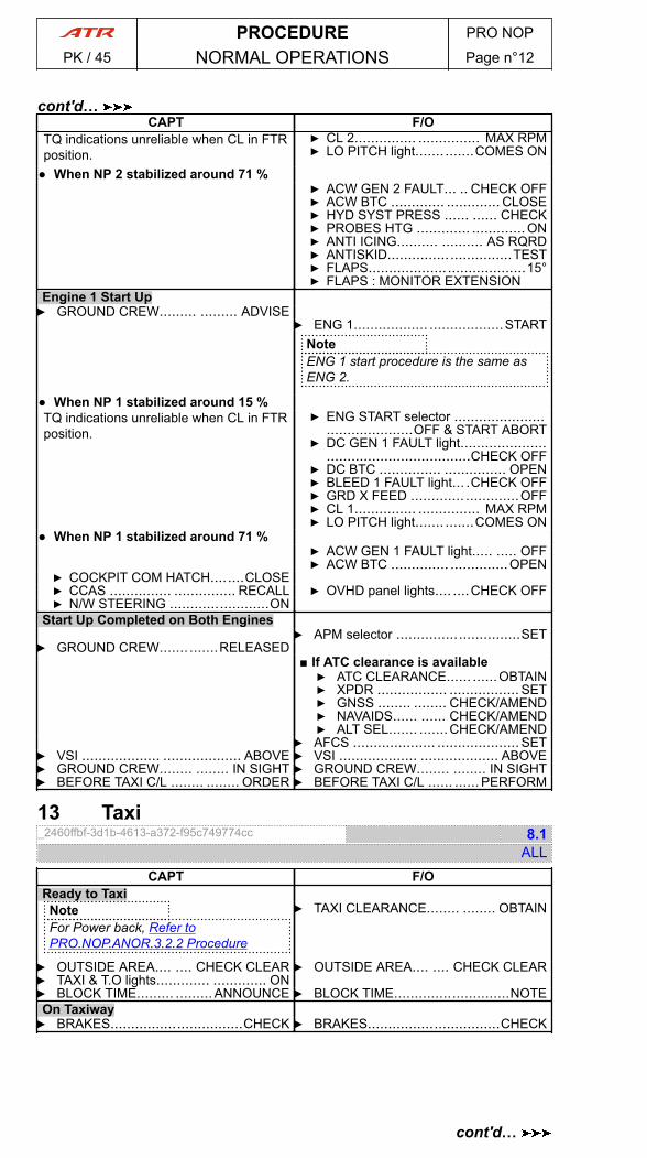
CAPT F/OTQ indications unreliable when CL in FTRposition.
▶ CL 2............... ............... MAX RPM▶ LO PITCH light....... .......COMES ON
● When NP 2 stabilized around 71 %▶ ACW GEN 2 FAULT... .. CHECK OFF▶ ACW BTC ............. ............. CLOSE▶ HYD SYST PRESS ...... ...... CHECK▶ PROBES HTG ............. .............ON▶ ANTI ICING.......... .......... AS RQRD▶ ANTISKID............... ...............TEST▶ FLAPS......................................15°▶ FLAPS : MONITOR EXTENSION
Engine 1 Start Up▶ GROUND CREW......... ......... ADVISE
▶ ENG 1.................. ..................STARTNoteENG 1 start procedure is the same asENG 2.
● When NP 1 stabilized around 15 %TQ indications unreliable when CL in FTRposition.
▶ ENG START selector ...........................................OFF & START ABORT
▶ DC GEN 1 FAULT light........................................................CHECK OFF
▶ DC BTC ............... ............... OPEN▶ BLEED 1 FAULT light... .CHECK OFF▶ GRD X FEED ............. .............OFF▶ CL 1............... ............... MAX RPM▶ LO PITCH light....... .......COMES ON
● When NP 1 stabilized around 71 %▶ ACW GEN 1 FAULT light..... ..... OFF▶ ACW BTC .............. ..............OPEN
▶ COCKPIT COM HATCH........CLOSE▶ CCAS ............... ............... RECALL ▶ OVHD panel lights.... ....CHECK OFF▶ N/W STEERING ........................ON
Start Up Completed on Both Engines▶ APM selector ..............................SET
▶ GROUND CREW....... .......RELEASED■ If ATC clearance is available▶ ATC CLEARANCE...... ......OBTAIN▶ XPDR ................. ................. SET▶ GNSS ........ ........ CHECK/AMEND▶ NAVAIDS...... ...... CHECK/AMEND▶ ALT SEL....... .......CHECK/AMEND
▶ AFCS .................... ....................SET▶ VSI ................... ................... ABOVE ▶ VSI ................... ................... ABOVE▶ GROUND CREW........ ........ IN SIGHT ▶ GROUND CREW........ ........ IN SIGHT▶ BEFORE TAXI C/L ........ ........ ORDER ▶ BEFORE TAXI C/L ...... ......PERFORM
13 Taxi_2460ffbf-3d1b-4613-a372-f95c749774cc 8.1
ALLCAPT F/O
Ready to TaxiNoteFor Power back, Refer toPRO.NOP.ANOR.3.2.2 Procedure
▶ TAXI CLEARANCE........ ........ OBTAIN
▶ OUTSIDE AREA.... .... CHECK CLEAR ▶ OUTSIDE AREA.... .... CHECK CLEAR▶ TAXI & T.O lights............. ............. ON▶ BLOCK TIME......... .........ANNOUNCE ▶ BLOCK TIME............................NOTEOn Taxiway▶ BRAKES................................CHECK ▶ BRAKES................................CHECK
PROCEDURE PRO NOP
PK / 45 NORMAL OPERATIONS Page n°12
cont'd…
cont'd…
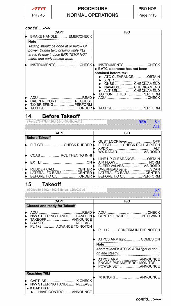
CAPT F/O▶ BRAKE HANDLE.... .... EMER/CHECK
NoteTaxiing should be done at or below GIpower. During taxi, braking while PLsare in FI may induce BRK TEMP HOTalarm and early brakes wear.
▶ INSTRUMENTS......................CHECK ▶ INSTRUMENTS......................CHECK■ If ATC clearance has not beenobtained before taxi▶ ATC CLEARANCE...... ......OBTAIN▶ XPDR ................. ................. SET▶ GNSS ........ ........ CHECK/AMEND▶ NAVAIDS...... ...... CHECK/AMEND▶ ALT SEL....... .......CHECK/AMEND
▶ T.O CONFIG TEST ............PERFORM▶ ADU ........................................READ ▶ ADU .................. .................. CHECK▶ CABIN REPORT........ ........ REQUEST▶ T.O BRIEFING ......... .........PERFORM▶ TAXI C/L ............... ............... ORDER ▶ TAXI C/L ............. .............PERFORM
14 Before Takeoff_c7e4a576-77fd-426d-854c-00c8bcfed421 REV 5.1
ALLCAPT F/O
Before Takeoff▶ GUST LOCK lever ........... ........... OFF
▶ FLT CTL ........ ........ CHECK RUDDER ▶ FLT CTL ....... . CHECK ROLL & PITCH▶ XPDR ........................................ ALT▶ WX RADAR............ ............AS RQRD
▶ CCAS ........ ........ RCL THEN TO INHI▶ LINE UP CLEARANCE............OBTAIN
▶ EXT LT ........................................ON ▶ AIR FLOW .............. .............. NORM▶ BLEED VALVES......... .........AS RQRD
▶ RUDDER CAM.......... .......... CENTER ▶ OVERHEAD panel ....................SCAN▶ LATERAL FD BARS....... .......CENTER ▶ LATERAL FD BARS....... .......CENTER▶ BEFORE T.O C/L ......... ......... ORDER ▶ BEFORE T.O C/L ....... .......PERFORM
15 Takeoff_e308bb80-6492-4362-81fc-ba1e25c037e6 6.1
ALLCAPT F/O
Cleared and ready for Takeoff
▶ ADU ........................................READ ▶ ADU .................. .................. CHECK▶ N/W STEERING HANDLE ... HAND ON ▶ CONTROL WHEEL..... ..... INTO WIND▶ TAKEOFF ........... ...........ANNOUNCE▶ BRAKES ............. ............. RELEASE▶ PL 1+2...... ...... ADVANCE TO NOTCH
▶ PL 1+2....... CONFIRM IN THE NOTCH
▶ ATPCS ARM light...... ...... COMES ONNoteAbort takeoff if ATPCS ARM light is noton and steady.
▶ ATPCS ARM ......... ......... ANNOUNCE▶ ENGINE PARAMETERS : MONITOR▶ POWER SET ..................ANNOUNCE
Reaching 70kt▶ 70 KNOTS .......... .......... ANNOUNCE
▶ CAPT IAS ............ ............ X CHECK▶ N/W STEERING HANDLE... .RELEASE■ If CAPT is PF▶ I HAVE CONTROL ... . ANNOUNCE
PROCEDURE PRO NOP
PK / 45 NORMAL OPERATIONS Page n°13
cont'd…
cont'd…

CAPT F/O
■ If F/O is PF▶ YOU HAVE CONTROL .................
................................ ANNOUNCE
■ If F/O is PF▶ I HAVE CONTROL ... . ANNOUNCE
PF PMReaching V1
▶ V1 ................ ................ ANNOUNCE
CAPT F/O▶ PL 1+2 ............... ...............RELEASE
PF PMReaching VR
▶ ROTATE ............ ............ANNOUNCEWhen V1 = VR announce V1/ROTATE.
▶ PITCH ....... ....... ROTATE SMOOTHLYAfter Liftoff
▶ POSITIVE CLIMB ..... ..... ANNOUNCE▶ GEAR UP............... ...............ORDER
▶ LDG GEAR lever ............. .............UP▶ YAW DAMPER ....................ENGAGE▶ TAXI & T.O lights ............ ............ OFF
16 After Takeoff_197c21cc-3407-4784-8286-8a5d32010407 2.3
ALLPF PM
Passing Acceleration Altitude▶ CLIMB PROCEDURE ...... ...... ORDER▶ PL 1+2....... CONFIRM IN THE NOTCH
▶ PWR MGT ................ ................ CLB▶ NP ............... ............... CHECK 82 %
▶ IAS .............. .............. ORDER 160 kt▶ IAS ................ ................ 160 kt SET
▶ SPEED BUG .................... 160 kt SET ▶ SPEED BUG .................... 160 kt SET■ If climbing at high rate▶ IAS ......................ORDER VALUE
▶ IAS ............................................SET▶ SPEED BUG............... ............... SET ▶ SPEED BUG............... ............... SET
■ If bleeds OFF takeoff▶ BLEED VALVES........... ...........ON
Passing VmLB0▶ FLAPS 0................................ORDER
▶ FLAPS..............................SELECT 0°Passing VmHB0■ If HDG Mode departure▶ BANK............... ............... SEL HI
■ If NAV Mode departure▶ NAV ............. ............. LNAV SET
Reaching Transition Altitude▶ ALTIMETER.......... .......... STANDARD ▶ ALTIMETER.......... .......... STANDARD▶ ALTIMETERS.......... .......... X CHECK ▶ ALTIMETERS.......... .......... X CHECK▶ AFTER TAKEOFF C/L ............ORDER ▶ AFTER TAKEOFF C/L ....... PERFORM
17 Climb - Cruise_13f027f8-9a87-4558-80a0-6f5e8cc996bf 3.0
ALLPF PM
Climbing Through FL100▶ LDG light.................. ..................OFF▶ PRESSURIZATION...... ...... MONITOR
PROCEDURE PRO NOP
PK / 45 NORMAL OPERATIONS Page n°14
cont'd…
cont'd…
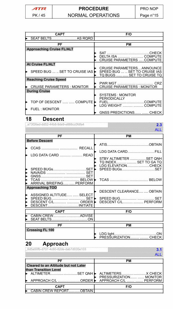
CAPT F/O▶ SEAT BELTS........... ........... AS RQRD
PF PMApproaching Cruise FL/ALT
▶ SAT ......................................CHECK▶ DELTA ISA ........... ........... COMPUTE▶ CRUISE PARAMETERS ... .COMPUTE
At Cruise FL/ALT▶ CRUISE PARAMETERS... ANNOUNCE
▶ SPEED BUG ... .. SET TO CRUISE IAS ▶ SPEED BUG ... .. SET TO CRUISE IAS▶ TQ BUGS ..... ..... SET TO CRUISE TQ
Reaching Cruise Speed▶ PWR MGT ................ ................ CRZ
▶ CRUISE PARAMETERS : MONITOR ▶ CRUISE PARAMETERS : MONITORDuring Cruise
▶ SYSTEMS : MONITORPERIODICALLY
▶ TOP OF DESCENT ..... ..... COMPUTE ▶ FUEL................................COMPUTE▶ LDG WEIGHT ......... ......... COMPUTE
▶ FUEL : MONITOR▶ GNSS PREDICTIONS...... ...... CHECK
18 Descent_a73f26ed-dd52-44b8-9de9-e888cc0fdfa4 2.3
ALLPF PM
Before Descent▶ ATIS......................................OBTAIN
▶ CCAS ................ ................ RECALL▶ LDG DATA CARD............ ............FILL
▶ LDG DATA CARD .......... .......... READ▶ STBY ALTIMETER ..............SET QNH▶ TQ INDEX......... ......... SET TO GA TQ▶ LDG ELEVATION....................CHECK
▶ SPEED BUGs..............................SET ▶ SPEED BUGs..............................SET▶ NAVAIDS ................. ................. SET▶ GNSS.................... .................... SET▶ TCAS ................. ................. BELOW ▶ TCAS ................. ................. BELOW▶ ARRIVAL BRIEFING..... ..... PERFORMApproaching TOD
▶ DESCENT CLEARANCE.... .... OBTAIN▶ ASSIGNED ALTITUDE..... ..... SELECT▶ SPEED BUG............... ............... SET ▶ SPEED BUG............... ............... SET▶ DESCENT C/L........... ........... ORDER▶ DESCENT............................INITIATE
▶ DESCENT C/L......... ......... PERFORM
CAPT F/O▶ CABIN CREW........................ADVISE▶ SEAT BELTS................ ................ON
PF PMCrossing FL 100
▶ LDG light......................................ON▶ PRESSURIZATION........ ........ CHECK
20 Approach_6d5a50fb-d707-4c60-82de-dab7d035e103 3.1
ALLPF PM
Cleared to an Altitude but not Laterthan Transition Level▶ ALTIMETER............ ............SET QNH ▶ ALTIMETERS......................X CHECK
▶ PRESSURIZATION...... ...... MONITOR▶ APPROACH C/L ....................ORDER ▶ APPROACH C/L ....... ....... PERFORM
CAPT F/O▶ CABIN CREW REPORT..........OBTAIN
PROCEDURE PRO NOP
PK / 45 NORMAL OPERATIONS Page n°15
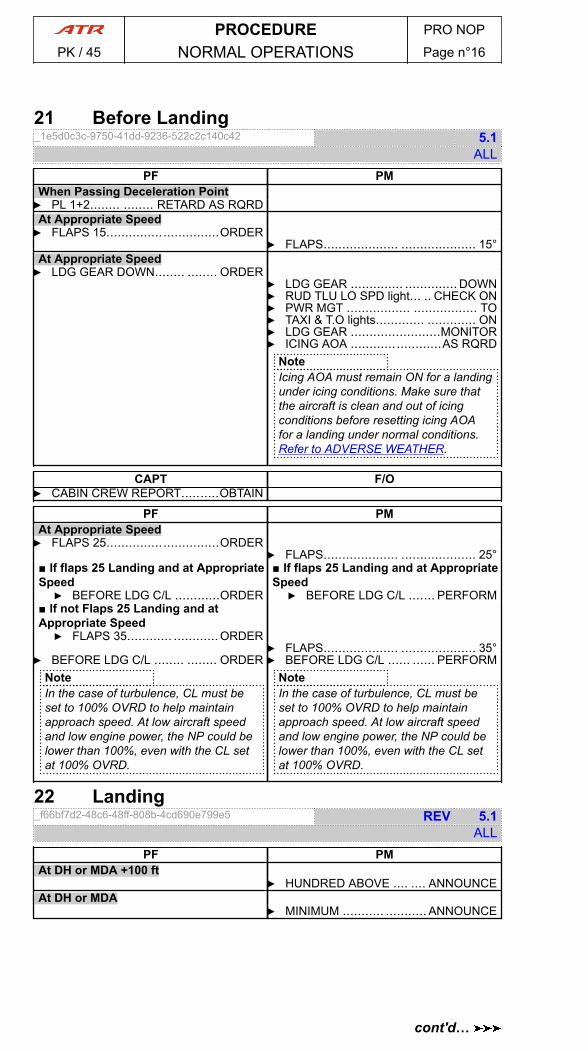
21 Before Landing_1e5d0c3c-9750-41dd-9236-522c2c140c42 5.1
ALLPF PM
When Passing Deceleration Point▶ PL 1+2........ ........ RETARD AS RQRDAt Appropriate Speed▶ FLAPS 15..............................ORDER
▶ FLAPS.................... .................... 15°At Appropriate Speed▶ LDG GEAR DOWN........ ........ ORDER
▶ LDG GEAR .............. .............. DOWN▶ RUD TLU LO SPD light... .. CHECK ON▶ PWR MGT ................. ................. TO▶ TAXI & T.O lights............. ............. ON▶ LDG GEAR ........................MONITOR▶ ICING AOA ........................AS RQRD
NoteIcing AOA must remain ON for a landingunder icing conditions. Make sure thatthe aircraft is clean and out of icingconditions before resetting icing AOAfor a landing under normal conditions.Refer to ADVERSE WEATHER.
CAPT F/O▶ CABIN CREW REPORT..........OBTAIN
PF PMAt Appropriate Speed▶ FLAPS 25..............................ORDER
▶ FLAPS.................... .................... 25°■ If flaps 25 Landing and at AppropriateSpeed▶ BEFORE LDG C/L ............ORDER
■ If flaps 25 Landing and at AppropriateSpeed▶ BEFORE LDG C/L ....... PERFORM
■ If not Flaps 25 Landing and atAppropriate Speed▶ FLAPS 35............ ............ORDER
▶ FLAPS.................... .................... 35°▶ BEFORE LDG C/L ........ ........ ORDER
NoteIn the case of turbulence, CL must beset to 100% OVRD to help maintainapproach speed. At low aircraft speedand low engine power, the NP could belower than 100%, even with the CL setat 100% OVRD.
▶ BEFORE LDG C/L ...... ...... PERFORMNoteIn the case of turbulence, CL must beset to 100% OVRD to help maintainapproach speed. At low aircraft speedand low engine power, the NP could belower than 100%, even with the CL setat 100% OVRD.
22 Landing_f66bf7d2-48c6-48ff-808b-4cd690e799e5 REV 5.1
ALLPF PM
At DH or MDA +100 ft▶ HUNDRED ABOVE .... .... ANNOUNCE
At DH or MDA▶ MINIMUM ........... ........... ANNOUNCE
PROCEDURE PRO NOP
PK / 45 NORMAL OPERATIONS Page n°16
cont'd…
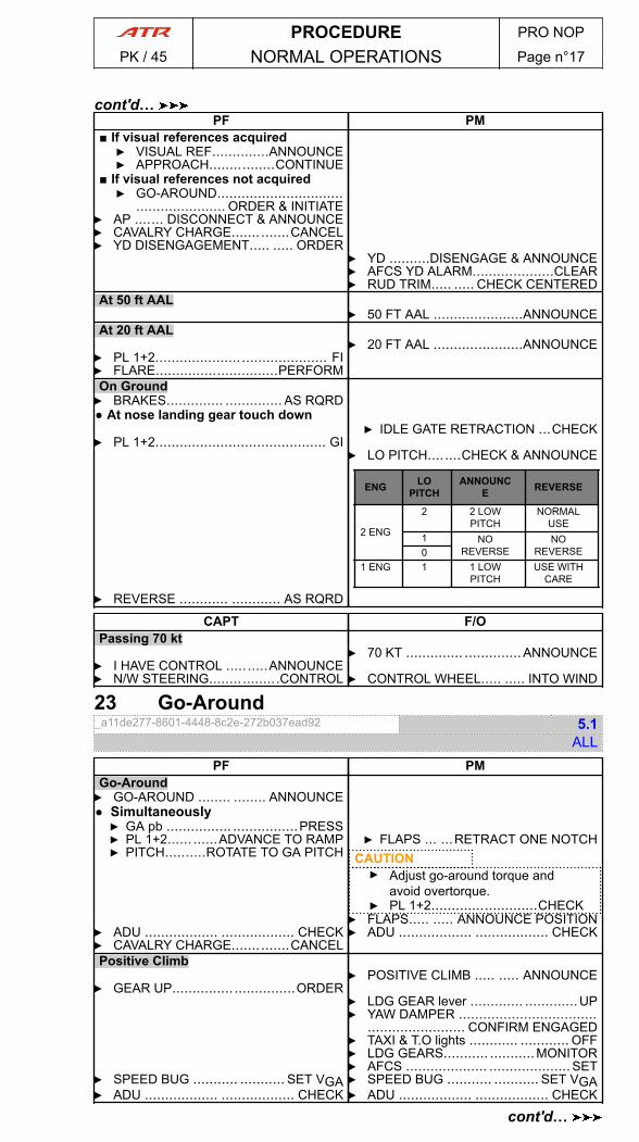
PF PM■ If visual references acquired▶ VISUAL REF..............ANNOUNCE▶ APPROACH................CONTINUE
■ If visual references not acquired▶ GO-AROUND...............................
...................... ORDER & INITIATE▶ AP ....... DISCONNECT & ANNOUNCE▶ CAVALRY CHARGE....... .......CANCEL▶ YD DISENGAGEMENT..... ..... ORDER
▶ YD ..........DISENGAGE & ANNOUNCE▶ AFCS YD ALARM....................CLEAR▶ RUD TRIM..... ..... CHECK CENTERED
At 50 ft AAL▶ 50 FT AAL ......................ANNOUNCE
At 20 ft AAL▶ 20 FT AAL ......................ANNOUNCE
▶ PL 1+2.......................................... FI▶ FLARE..............................PERFORMOn Ground▶ BRAKES.............. .............. AS RQRD● At nose landing gear touch down
▶ IDLE GATE RETRACTION ...CHECK▶ PL 1+2.......................................... GI
▶ LO PITCH........CHECK & ANNOUNCE
ENG LOPITCH
ANNOUNCE REVERSE
2 ENG
2 2 LOWPITCH
NORMALUSE
1 NOREVERSE
NOREVERSE0
1 ENG 1 1 LOWPITCH
USE WITHCARE
▶ REVERSE ............ ............ AS RQRD
CAPT F/OPassing 70 kt
▶ 70 KT .............. ..............ANNOUNCE▶ I HAVE CONTROL ..........ANNOUNCE▶ N/W STEERING................ .CONTROL ▶ CONTROL WHEEL..... ..... INTO WIND
23 Go-Around_a11de277-8601-4448-8c2e-272b037ead92 5.1
ALLPF PM
Go-Around▶ GO-AROUND ........ ........ ANNOUNCE● Simultaneously▶ GA pb ................ ................PRESS▶ PL 1+2...... ......ADVANCE TO RAMP▶ PITCH..........ROTATE TO GA PITCH
▶ FLAPS ... ...RETRACT ONE NOTCHCAUTION▶ Adjust go-around torque and
avoid overtorque.▶ PL 1+2..........................CHECK
▶ FLAPS..... ..... ANNOUNCE POSITION▶ ADU .................. .................. CHECK ▶ ADU .................. .................. CHECK▶ CAVALRY CHARGE....... .......CANCELPositive Climb
▶ POSITIVE CLIMB ..... ..... ANNOUNCE▶ GEAR UP............... ...............ORDER
▶ LDG GEAR lever ............. .............UP▶ YAW DAMPER ..................................
........................ CONFIRM ENGAGED▶ TAXI & T.O lights ............ ............ OFF▶ LDG GEARS........... ...........MONITOR▶ AFCS .................... ....................SET
▶ SPEED BUG ........... ........... SET VGA ▶ SPEED BUG ........... ........... SET VGA▶ ADU .................. .................. CHECK ▶ ADU .................. .................. CHECK
PROCEDURE PRO NOP
PK / 45 NORMAL OPERATIONS Page n°17
cont'd…
cont'd…
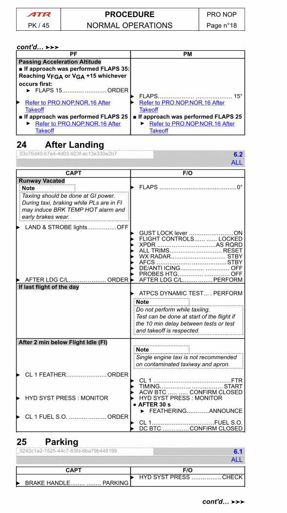
PF PMPassing Acceleration Altitude■ If approach was performed FLAPS 35:Reaching VFGA or VGA +15 whicheveroccurs first:▶ FLAPS 15............ ............ORDER
▶ FLAPS.................... .................... 15°▶ Refer to PRO.NOP.NOR.16 After
Takeoff▶ Refer to PRO.NOP.NOR.16 After
Takeoff■ If approach was performed FLAPS 25▶ Refer to PRO.NOP.NOR.16 After
Takeoff
■ If approach was performed FLAPS 25▶ Refer to PRO.NOP.NOR.16 After
Takeoff
24 After Landing_03c76d40-b7e4-4d03-923f-ac13e330e2b7 6.2
ALLCAPT F/O
Runway VacatedNoteTaxiing should be done at GI power.During taxi, braking while PLs are in FImay induce BRK TEMP HOT alarm andearly brakes wear.
▶ LAND & STROBE lights................OFF
▶ FLAPS ..........................................0°
▶ GUST LOCK lever ........................ON▶ FLIGHT CONTROLS...... ...... LOCKED▶ XPDR ................................AS RQRD▶ ALL TRIMS.............. .............. RESET▶ WX RADAR.............................. STBY▶ AFCS ................... ...................STBY▶ DE/ANTI ICING............. ............. OFF▶ PROBES HTG.............. .............. OFF
▶ AFTER LDG C/L.......... .......... ORDER ▶ AFTER LDG C/L........ ........PERFORMIf last flight of the day
▶ ATPCS DYNAMIC TEST... . PERFORMNoteDo not perform while taxiing.Test can be done at start of the flight ifthe 10 min delay between tests or testand takeoff is respected.
After 2 min below Flight Idle (FI)NoteSingle engine taxi is not recommendedon contaminated taxiway and apron.
▶ CL 1 FEATHER........... ...........ORDER▶ CL 1 ..................... .....................FTR▶ TIMING................. ................. START▶ ACW BTC ..... ..... CONFIRM CLOSED
▶ HYD SYST PRESS : MONITOR ▶ HYD SYST PRESS : MONITOR● AFTER 30 s▶ FEATHERING............ANNOUNCE
▶ CL 1 FUEL S.O. .......... .......... ORDER▶ CL 1..................................FUEL S.O.▶ DC BTC ....... .......CONFIRM CLOSED
25 Parking_0242c1a2-1525-44c7-83fd-6ba79b448199 6.1
ALLCAPT F/O
▶ HYD SYST PRESS ........ ........CHECK▶ BRAKE HANDLE........ ........ PARKING
PROCEDURE PRO NOP
PK / 45 NORMAL OPERATIONS Page n°18
cont'd…
cont'd…
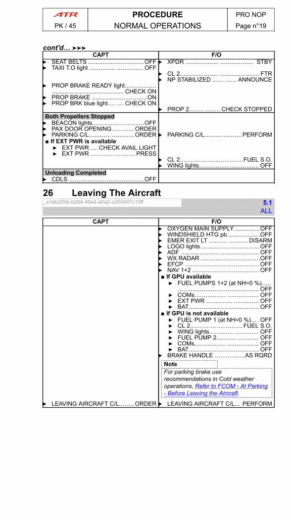
CAPT F/O▶ SEAT BELTS ..............................OFF▶ TAXI T.O light .............. .............. OFF
▶ XPDR .................. .................. STBY
▶ CL 2..................... ..................... FTR▶ NP STABILIZED ...... ...... ANNOUNCE
▶ PROP BRAKE READY light........................................................ CHECK ON
▶ PROP BRAKE ..............................ON▶ PROP BRK blue light.... .... CHECK ON
▶ PROP 2........ ........ CHECK STOPPEDBoth Propellers Stopped▶ BEACON lights............................OFF▶ PAX DOOR OPENING...... ......ORDER▶ PARKING C/L............ ............ ORDER ▶ PARKING C/L....................PERFORM■ If EXT PWR is available▶ EXT PWR ... .CHECK AVAIL LIGHT▶ EXT PWR ............ ............PRESS
▶ CL 2..................................FUEL S.O.▶ WING lights................ ................ OFF
Unloading Completed▶ CDLS .................... ....................OFF
26 Leaving The Aircraft_a1eb250e-b264-49e4-a0a2-e350547c10ff 5.1
ALLCAPT F/O
▶ OXYGEN MAIN SUPPLY..............OFF▶ WINDSHIELD HTG pb..................OFF▶ EMER EXIT LT .......... .......... DISARM▶ LOGO lights................................OFF▶ ADF ..................... .....................OFF▶ WX RADAR ................................OFF▶ EFCP .................... ....................OFF▶ NAV 1+2 .................. ..................OFF■ If GPU available▶ FUEL PUMPS 1+2 (at NH=0 %).....
............................................ OFF▶ COMs................. ................. OFF▶ EXT PWR .............. .............. OFF▶ BAT................... ...................OFF
■ If GPU is not available▶ FUEL PUMP 1 (at NH=0 %)... . OFF▶ CL 2.............. ..............FUEL S.O.▶ WING lights............. ............. OFF▶ FUEL PUMP 2........... ........... OFF▶ COMs................. ................. OFF▶ BAT................... ...................OFF
▶ BRAKE HANDLE ................AS RQRDNoteFor parking brake userecommendations in Cold weatheroperations, Refer to FCOM - At Parking- Before Leaving the Aircraft.
▶ LEAVING AIRCRAFT C/L.... ....ORDER ▶ LEAVING AIRCRAFT C/L... PERFORM
PROCEDURE PRO NOP
PK / 45 NORMAL OPERATIONS Page n°19
cont'd…

PAGE
INTENTIONALLY
LEFT BLANK
PROCEDURE PRO NOP
PK / 45 NORMAL OPERATIONS Page n°20

1 Procedure for Icing Conditions_427296d6-ef0a-4d94-88d2-0e48d5b65f93 5.0
ALL
PROCEDURE FOR ICING CONDITIONS▶ IAS : MAINTAIN AT OR ABOVE ICING BUG▶ ANTI ICING systems.................................. .................................. ON▶ ICE ACCRETION : MONITOR● When ice accretion is observed/detected▶ DE ICING systems.................................. ..................................ON● In FLAPS 0 configuration▶ IAS : MAINTAIN AT OR ABOVE ICING BUG +10 kt
▶ IAS & V/S : MONITORNoteRefer to AFM - SEVERE ICING DETECTION for severe icing indicationsinformation.
■ If any severe icing indication▶ SEVERE ICING procedure ( E99.08 ) ....................................APPLY
● When leaving icing conditions▶ ANTI ICING & DE ICING systems.......... .......... TURN OFF AS RQRD
● When aircraft is visually verified clear of iceNoteThe aircraft is considered clear of ice when IEP is free of ice.
▶ ICING AOA pb ........................................................................OFF▶ NORMAL SPEED : USE
_0542fc4c-6eb7-439a-b570-9935ed5ffbb0 0.1ALL
A30.16SEVERE ICING DETECTIONSEVERE ICING main indications :
- Ice covering all/substantial parts of unheated side window (visualcue)
- Unable to maintain IAS above ICING BUG +10 kt- Unable to maintain V/S above 100 ft/min AVERAGE at icing bug
+10 kt- Abnormal vibrations
■ If any severe icing indication :▶ SEVERE ICING procedure ( E99.08 ) ....................... ....................... APPLY
Supplementary indications:- Water splashing/streaming on the windshield- Unusual extensive ice accreted on the airframe in areas not normally
observed to collect ice- Accumulation of ice on the lower surface of the wing aft of the protected
areas- Accumulation of ice on propeller spinner farther aft than normally observed
Weather conditions that can result in severe in-flight icing:- Visible rain at temperatures close to 0 °C (SAT)- Droplets that splash or splatter on impact at temperature close to 0 °C (SAT).
3 Cruise Speed Low_afeb0a25-4d5c-4e09-aa73-38ec29bdc850 0.1
ALL
CRUISE SPEED LOW▶ ICING CONDITIONS : MONITOR
PROCEDURE PRO NOP
PK / 45 NORMAL OPERATIONS Page n°01
cont'd…
▶ SPEED : MONITOR
PROCEDURE PRO NOP
PK / 45 NORMAL OPERATIONS Page n°02
cont'd…
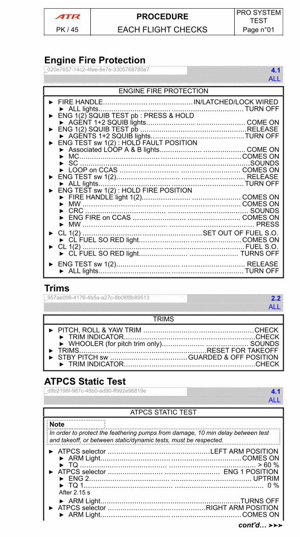
Engine Fire Protection_020e7657-14c2-4fee-8e7e-3305768780e7 4.1
ALL
ENGINE FIRE PROTECTION▶ FIRE HANDLE..................... ..................... IN/LATCHED/LOCK WIRED▶ ALL lights.................................. .................................. TURN OFF
▶ ENG 1(2) SQUIB TEST pb : PRESS & HOLD▶ AGENT 1+2 SQUIB lights....................... ....................... COME ON
▶ ENG 1(2) SQUIB TEST pb ..................................................RELEASE▶ AGENTS 1+2 SQUIB lights............................................TURN OFF
▶ ENG TEST sw 1(2) : HOLD FAULT POSITION▶ Associated LOOP A & B lights.................... .................... COME ON▶ MC...................................... ......................................COMES ON▶ SC ................................................................................SOUNDS▶ LOOP on CCAS ............................ ............................ COMES ON
▶ ENG TEST sw 1(2).............................. .............................. RELEASE▶ ALL lights.................................. .................................. TURN OFF
▶ ENG TEST sw 1(2) : HOLD FIRE POSITION▶ FIRE HANDLE light 1(2)....................... ....................... COMES ON▶ MW ..................................... ..................................... COMES ON▶ CRC ...................................... ...................................... SOUNDS▶ ENG FIRE on CCAS ......................... ......................... COMES ON▶ MW ........................................ ........................................ PRESS
▶ CL 1(2) ............................ ............................SET OUT OF FUEL S.O.▶ CL FUEL SO RED light........................ ........................COMES ON
▶ CL 1(2) ...................................... ......................................FUEL S.O.▶ CL FUEL SO RED light....................... ....................... TURNS OFF
▶ ENG TEST sw 1(2).............................. .............................. RELEASE▶ ALL lights.................................. .................................. TURN OFF
Trims_957ae098-4176-4b5a-a27c-8b08f8b89513 2.2
ALL
TRIMS▶ PITCH, ROLL & YAW TRIM ....................................................CHECK▶ TRIM INDICATOR..............................................................CHECK▶ WHOOLER (for pitch trim only).................... .................... SOUNDS
▶ TRIMS............................................................RESET FOR TAKEOFF▶ STBY PITCH sw .................. ..................GUARDED & OFF POSITION▶ TRIM INDICATOR..............................................................CHECK
ATPCS Static Test_d9b2198f-987c-48b0-ad90-ff992e96819e 4.1
ALL
ATPCS STATIC TEST
NoteIn order to protect the feathering pumps from damage, 10 min delay between testand takeoff, or between static/dynamic tests, must be respected.
▶ ATPCS selector ................................................LEFT ARM POSITION▶ ARM Light................................. .................................COMES ON▶ TQ ......................................... ......................................... > 60 %
▶ ATPCS selector .......................... .......................... ENG 1 POSITION▶ ENG 2...................................... ...................................... UPTRIM▶ TQ 1.......................................... .......................................... 0 %After 2.15 s▶ ARM Light..................................................................TURNS OFF
▶ ATPCS selector ..............................................RIGHT ARM POSITION▶ ARM Light................................. .................................COMES ON
PROCEDURE PRO SYSTEMTEST
PK / 45 EACH FLIGHT CHECKS Page n°01
cont'd…
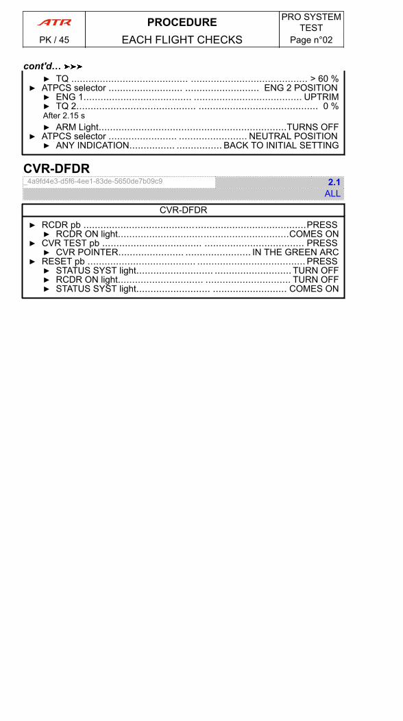
▶ TQ ......................................... ......................................... > 60 %▶ ATPCS selector .......................... .......................... ENG 2 POSITION▶ ENG 1...................................... ...................................... UPTRIM▶ TQ 2.......................................... .......................................... 0 %After 2.15 s▶ ARM Light..................................................................TURNS OFF
▶ ATPCS selector ........................ ........................ NEUTRAL POSITION▶ ANY INDICATION................ ................ BACK TO INITIAL SETTING
CVR-DFDR_4a9fd4e3-d5f6-4ee1-83de-5650de7b09c9 2.1
ALL
CVR-DFDR▶ RCDR pb ..............................................................................PRESS▶ RCDR ON light............................................................COMES ON
▶ CVR TEST pb ................................... ................................... PRESS▶ CVR POINTER....................... ....................... IN THE GREEN ARC
▶ RESET pb ...................................... ...................................... PRESS▶ STATUS SYST light........................... ........................... TURN OFF▶ RCDR ON light.............................. .............................. TURN OFF▶ STATUS SYST light.......................... .......................... COMES ON
PROCEDURE PRO SYSTEMTEST
PK / 45 EACH FLIGHT CHECKS Page n°02
cont'd…
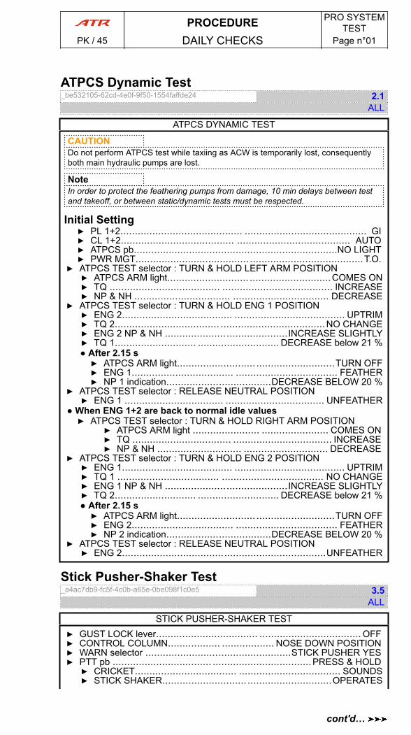
ATPCS Dynamic Test_be532105-62cd-4e0f-9f50-1554faffde24 2.1
ALL
ATPCS DYNAMIC TEST
CAUTIONDo not perform ATPCS test while taxiing as ACW is temporarily lost, consequentlyboth main hydraulic pumps are lost.
NoteIn order to protect the feathering pumps from damage, 10 min delays between testand takeoff, or between static/dynamic tests must be respected.
Initial Setting▶ PL 1+2.......................................... .......................................... GI▶ CL 1+2....................................... ....................................... AUTO▶ ATPCS pb......................................................................NO LIGHT▶ PWR MGT....................................... .......................................T.O.
▶ ATPCS TEST selector : TURN & HOLD LEFT ARM POSITION▶ ATPCS ARM light............................ ............................COMES ON▶ TQ ...................................... ...................................... INCREASE▶ NP & NH ................................. ................................. DECREASE
▶ ATPCS TEST selector : TURN & HOLD ENG 1 POSITION▶ ENG 2...................................... ...................................... UPTRIM▶ TQ 2.................................... ....................................NO CHANGE▶ ENG 2 NP & NH ..........................................INCREASE SLIGHTLY▶ TQ 1............................ ............................ DECREASE below 21 %● After 2.15 s▶ ATPCS ARM light........................... ...........................TURN OFF▶ ENG 1................................... ................................... FEATHER▶ NP 1 indication....................................DECREASE BELOW 20 %
▶ ATPCS TEST selector : RELEASE NEUTRAL POSITION▶ ENG 1 .................................. .................................. UNFEATHER
● When ENG 1+2 are back to normal idle values▶ ATPCS TEST selector : TURN & HOLD RIGHT ARM POSITION
▶ ATPCS ARM light ....................... ....................... COMES ON▶ TQ .................................. .................................. INCREASE▶ NP & NH ............................. ............................. DECREASE
▶ ATPCS TEST selector : TURN & HOLD ENG 2 POSITION▶ ENG 1...................................... ...................................... UPTRIM▶ TQ 1 ................................... ................................... NO CHANGE▶ ENG 1 NP & NH ..........................................INCREASE SLIGHTLY▶ TQ 2............................ ............................ DECREASE below 21 %● After 2.15 s▶ ATPCS ARM light........................... ...........................TURN OFF▶ ENG 2................................... ................................... FEATHER▶ NP 2 indication....................................DECREASE BELOW 20 %
▶ ATPCS TEST selector : RELEASE NEUTRAL POSITION▶ ENG 2......................................................................UNFEATHER
Stick Pusher-Shaker Test_a4ac7db9-fc5f-4c0b-a65e-0be098f1c0e5 3.5
ALL
STICK PUSHER-SHAKER TEST▶ GUST LOCK lever................................... ................................... OFF▶ CONTROL COLUMN.................. .................. NOSE DOWN POSITION▶ WARN selector ..................................................STICK PUSHER YES▶ PTT pb .................................. ..................................PRESS & HOLD▶ CRICKET................................... ................................... SOUNDS▶ STICK SHAKER............................. .............................OPERATES
PROCEDURE PRO SYSTEMTEST
PK / 45 DAILY CHECKS Page n°01
cont'd…
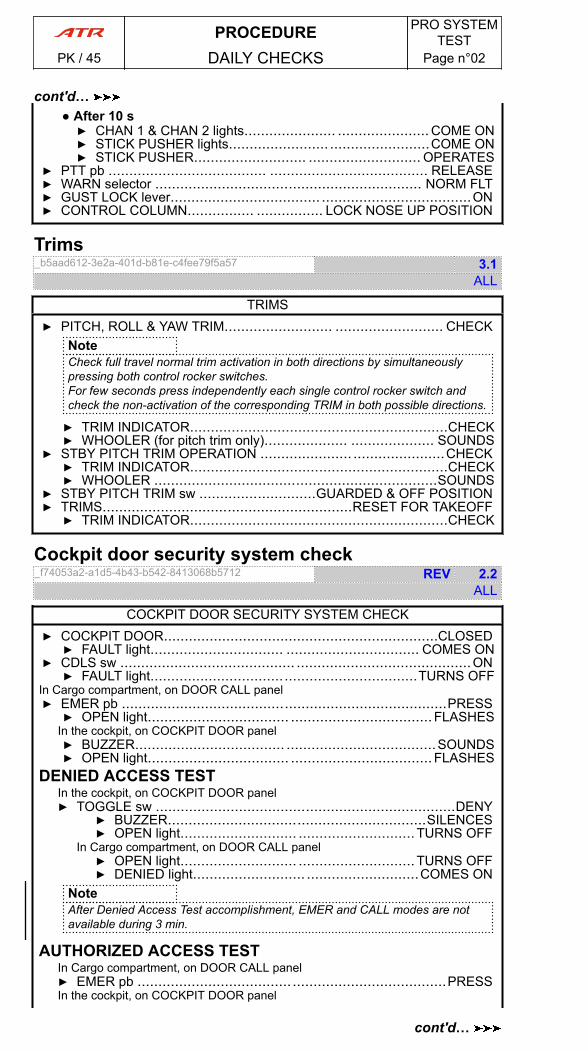
● After 10 s▶ CHAN 1 & CHAN 2 lights...................... ...................... COME ON▶ STICK PUSHER lights........................ ........................COME ON▶ STICK PUSHER........................... ........................... OPERATES
▶ PTT pb ...................................... ...................................... RELEASE▶ WARN selector ................................................................ NORM FLT▶ GUST LOCK lever.................................... ....................................ON▶ CONTROL COLUMN................ ................ LOCK NOSE UP POSITION
Trims_b5aad612-3e2a-401d-b81e-c4fee79f5a57 3.1
ALL
TRIMS▶ PITCH, ROLL & YAW TRIM.......................... .......................... CHECK
NoteCheck full travel normal trim activation in both directions by simultaneouslypressing both control rocker switches.For few seconds press independently each single control rocker switch andcheck the non-activation of the corresponding TRIM in both possible directions.
▶ TRIM INDICATOR..............................................................CHECK▶ WHOOLER (for pitch trim only).................... .................... SOUNDS
▶ STBY PITCH TRIM OPERATION ...................... ......................CHECK▶ TRIM INDICATOR..............................................................CHECK▶ WHOOLER ....................................................................SOUNDS
▶ STBY PITCH TRIM sw ............................GUARDED & OFF POSITION▶ TRIMS............................................................RESET FOR TAKEOFF▶ TRIM INDICATOR..............................................................CHECK
Cockpit door security system check_f74053a2-a1d5-4b43-b542-8413068b5712 REV 2.2
ALL
COCKPIT DOOR SECURITY SYSTEM CHECK▶ COCKPIT DOOR..................................................................CLOSED▶ FAULT light................................ ................................ COMES ON
▶ CDLS sw .......................................... ..........................................ON▶ FAULT light................................................................TURNS OFF
In Cargo compartment, on DOOR CALL panel▶ EMER pb ..............................................................................PRESS▶ OPEN light.................................. .................................. FLASHES
In the cockpit, on COCKPIT DOOR panel▶ BUZZER.................................... ....................................SOUNDS▶ OPEN light.................................. .................................. FLASHES
DENIED ACCESS TESTIn the cockpit, on COCKPIT DOOR panel▶ TOGGLE sw ........................................................................DENY
▶ BUZZER..............................................................SILENCES▶ OPEN light............................ ............................TURNS OFF
In Cargo compartment, on DOOR CALL panel▶ OPEN light............................ ............................TURNS OFF▶ DENIED light........................... ...........................COMES ON
NoteAfter Denied Access Test accomplishment, EMER and CALL modes are notavailable during 3 min.
AUTHORIZED ACCESS TESTIn Cargo compartment, on DOOR CALL panel▶ EMER pb ..................................... .....................................PRESSIn the cockpit, on COCKPIT DOOR panel
PROCEDURE PRO SYSTEMTEST
PK / 45 DAILY CHECKS Page n°02
cont'd…
cont'd…
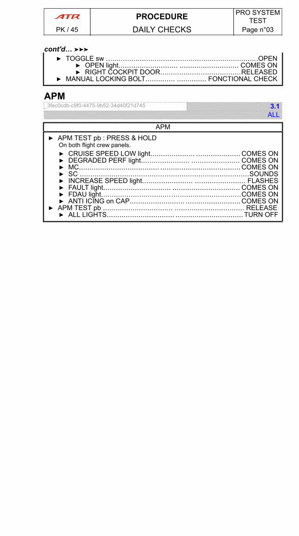
▶ TOGGLE sw ........................................................................OPEN▶ OPEN light............................ ............................ COMES ON▶ RIGHT COCKPIT DOOR......................................RELEASED
▶ MANUAL LOCKING BOLT.............. .............. FONCTIONAL CHECK
APM_3fec0cdb-c9f0-4475-9b52-34d40f21d745 3.1
ALL
APM▶ APM TEST pb : PRESS & HOLD
On both flight crew panels.▶ CRUISE SPEED LOW light..................... ..................... COMES ON▶ DEGRADED PERF light....................... ....................... COMES ON▶ MC...................................... ......................................COMES ON▶ SC ................................................................................SOUNDS▶ INCREASE SPEED light........................ ........................ FLASHES▶ FAULT light................................ ................................ COMES ON▶ FDAU light..................................................................COMES ON▶ ANTI ICING on CAP.......................... ..........................COMES ON
▶ APM TEST pb ................................. ................................. RELEASE▶ ALL LIGHTS................................ ................................ TURN OFF
PROCEDURE PRO SYSTEMTEST
PK / 45 DAILY CHECKS Page n°03
cont'd…
PAGE
INTENTIONALLY
LEFT BLANK
PROCEDURE PRO SYSTEMTEST
PK / 45 DAILY CHECKS Page n°04
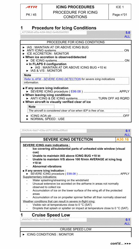
1 Procedure for Icing Conditions_427296d6-ef0a-4d94-88d2-0e48d5b65f93 5.0
ALL
PROCEDURE FOR ICING CONDITIONS▶ IAS : MAINTAIN AT OR ABOVE ICING BUG▶ ANTI ICING systems.................................. .................................. ON▶ ICE ACCRETION : MONITOR● When ice accretion is observed/detected▶ DE ICING systems.................................. ..................................ON● In FLAPS 0 configuration▶ IAS : MAINTAIN AT OR ABOVE ICING BUG +10 kt
▶ IAS & V/S : MONITORNoteRefer to AFM - SEVERE ICING DETECTION for severe icing indicationsinformation.
■ If any severe icing indication▶ SEVERE ICING procedure ( E99.08 ) ....................................APPLY
● When leaving icing conditions▶ ANTI ICING & DE ICING systems.......... .......... TURN OFF AS RQRD
● When aircraft is visually verified clear of iceNoteThe aircraft is considered clear of ice when IEP is free of ice.
▶ ICING AOA pb ........................................................................OFF▶ NORMAL SPEED : USE
_0542fc4c-6eb7-439a-b570-9935ed5ffbb0 0.1ALL
A30.16SEVERE ICING DETECTIONSEVERE ICING main indications :
- Ice covering all/substantial parts of unheated side window (visualcue)
- Unable to maintain IAS above ICING BUG +10 kt- Unable to maintain V/S above 100 ft/min AVERAGE at icing bug
+10 kt- Abnormal vibrations
■ If any severe icing indication :▶ SEVERE ICING procedure ( E99.08 ) ....................... ....................... APPLY
Supplementary indications:- Water splashing/streaming on the windshield- Unusual extensive ice accreted on the airframe in areas not normally
observed to collect ice- Accumulation of ice on the lower surface of the wing aft of the protected
areas- Accumulation of ice on propeller spinner farther aft than normally observed
Weather conditions that can result in severe in-flight icing:- Visible rain at temperatures close to 0 °C (SAT)- Droplets that splash or splatter on impact at temperature close to 0 °C (SAT).
1 Cruise Speed Low_afeb0a25-4d5c-4e09-aa73-38ec29bdc850 0.1
ALL
CRUISE SPEED LOW▶ ICING CONDITIONS : MONITOR
ICING PROCEDURES ICE 1
PK / 45 PROCEDURE FOR ICINGCONDITIONS Page n°01
cont'd…
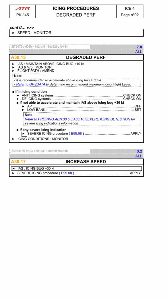
▶ SPEED : MONITOR
_2f79979d-d05b-4192-af81-3dc226e1b184 7.0ALL
A30.15 DEGRADED PERF▶ IAS : MAINTAIN ABOVE ICING BUG +10 kt▶ IAS & V/S : MONITOR▶ FLIGHT PATH : AMEND
Note- It is recommended to accelerate above icing bug + 30 kt.- Refer to OPSDATA to determine recommended maximum icing Flight Level.
■ If in icing condition▶ ANTI ICING systems ................................................................CHECK ON▶ DE ICING systems ................................. ................................. CHECK ON■ If not able to accelerate and maintain IAS above icing bug +30 kt▶ AP ............................................... ............................................... OFF▶ LOW BANK......................................... ......................................... SET
NoteRefer to PRO.NNO.ABN.30.5.3.A30.16 SEVERE ICING DETECTION forsevere icing indications information
■ If any severe icing indication▶ SEVERE ICING procedure ( E99.08 ) ..................... .....................APPLY
▶ ICING CONDITIONS : MONITOR
_540a3436-9a23-43cf-aa13-ad19fe5b6abb 3.2ALL
A30.17 INCREASE SPEED▶ IAS : ICING BUG +30 kt▶ SEVERE ICING procedure ( E99.08 ) ......................... ......................... APPLY
ICING PROCEDURES ICE 4
PK / 45 DEGRADED PERF Page n°02
cont'd…
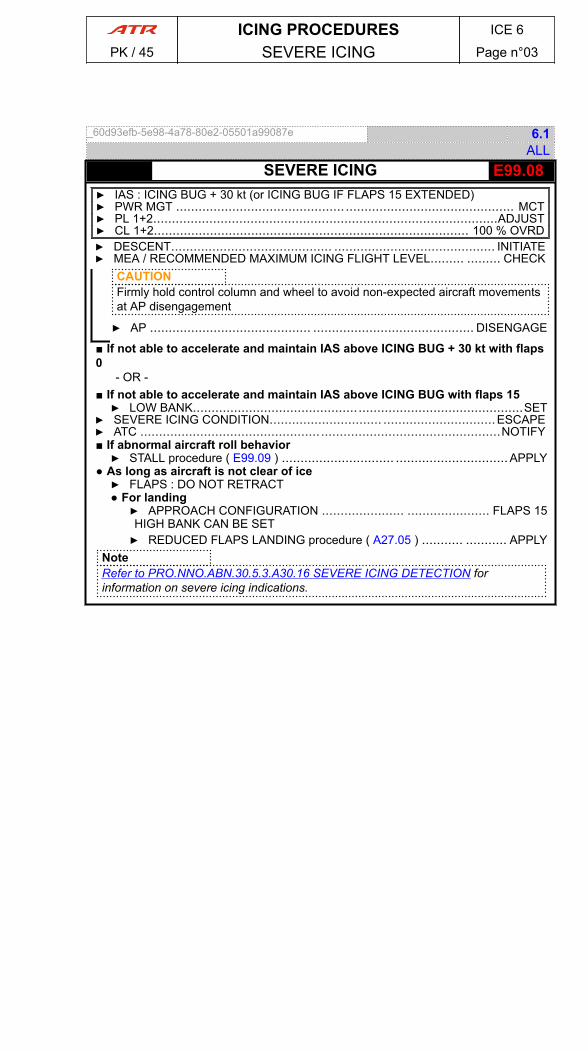
_60d93efb-5e98-4a78-80e2-05501a99087e 6.1ALL
- E99.08SEVERE ICING▶ IAS : ICING BUG + 30 kt (or ICING BUG IF FLAPS 15 EXTENDED)▶ PWR MGT ............................................. ............................................. MCT▶ PL 1+2............................................................................................ADJUST▶ CL 1+2.................................................................................... 100 % OVRD▶ DESCENT........................................... ........................................... INITIATE▶ MEA / RECOMMENDED MAXIMUM ICING FLIGHT LEVEL......... ......... CHECK
CAUTIONFirmly hold control column and wheel to avoid non-expected aircraft movementsat AP disengagement
▶ AP ........................................... ........................................... DISENGAGE
■ If not able to accelerate and maintain IAS above ICING BUG + 30 kt with flaps0
- OR -■ If not able to accelerate and maintain IAS above ICING BUG with flaps 15▶ LOW BANK........................................................................................SET
▶ SEVERE ICING CONDITION.............................. ..............................ESCAPE▶ ATC ................................................................................................NOTIFY■ If abnormal aircraft roll behavior▶ STALL procedure ( E99.09 ) .............................. ..............................APPLY
● As long as aircraft is not clear of ice▶ FLAPS : DO NOT RETRACT● For landing▶ APPROACH CONFIGURATION ...................... ...................... FLAPS 15HIGH BANK CAN BE SET▶ REDUCED FLAPS LANDING procedure ( A27.05 ) ........... ........... APPLY
NoteRefer to PRO.NNO.ABN.30.5.3.A30.16 SEVERE ICING DETECTION forinformation on severe icing indications.
ICING PROCEDURES ICE 6
PK / 45 SEVERE ICING Page n°03

PAGE
INTENTIONALLY
LEFT BLANK
ICING PROCEDURES ICE 6
PK / 45 SEVERE ICING Page n°04
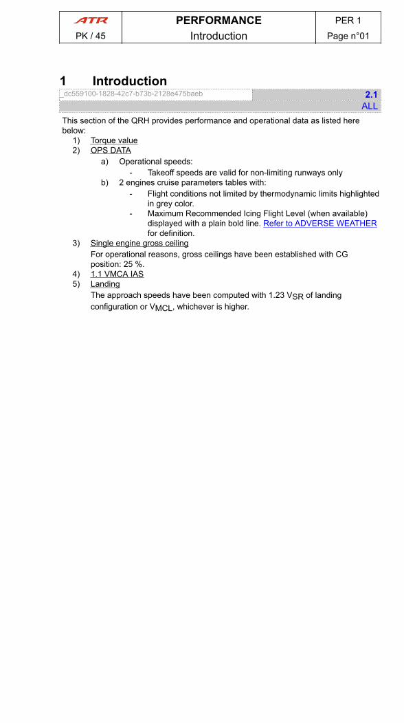
1 Introduction_dc559100-1828-42c7-b73b-2128e475baeb 2.1
ALLThis section of the QRH provides performance and operational data as listed herebelow:
1) Torque value2) OPS DATA
a) Operational speeds:- Takeoff speeds are valid for non-limiting runways only
b) 2 engines cruise parameters tables with:- Flight conditions not limited by thermodynamic limits highlighted
in grey color.- Maximum Recommended Icing Flight Level (when available)
displayed with a plain bold line. Refer to ADVERSE WEATHERfor definition.
3) Single engine gross ceilingFor operational reasons, gross ceilings have been established with CGposition: 25 %.
4) 1.1 VMCA IAS5) Landing
The approach speeds have been computed with 1.23 VSR of landingconfiguration or VMCL, whichever is higher.
PERFORMANCE PER 1
PK / 45 Introduction Page n°01

PAGE
INTENTIONALLY
LEFT BLANK
PERFORMANCE PER 1
PK / 45 Introduction Page n°02
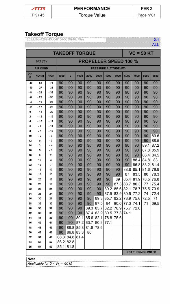
Takeoff Torque_205dcfbb-4262-43c6-8134-5330910c79ea 2.1
ALL
TAKEOFF TORQUE VC = 50 KTSAT (°C) PROPELLER SPEED 100 %
AIR COND PRESSURE ALTITUDE (FT)
OFF NORM HIGH -1000 0 1000 2000 3000 4000 5000 6000 7000 8000 8500
- 40 - 63 - 71 90 90 90 90 90 90 90 90 90 90 90- 10 - 27 - 35 90 90 90 90 90 90 90 90 90 90 90- 8 - 24 - 32 90 90 90 90 90 90 90 90 90 90 90- 6 - 22 - 30 90 90 90 90 90 90 90 90 90 90 90- 4 - 19 - 27 90 90 90 90 90 90 90 90 90 90 90- 2 - 17 - 25 90 90 90 90 90 90 90 90 90 90 900 - 14 - 22 90 90 90 90 90 90 90 90 90 90 902 - 12 - 19 90 90 90 90 90 90 90 90 90 90 904 - 10 - 17 90 90 90 90 90 90 90 90 90 90 906 - 7 - 14 90 90 90 90 90 90 90 90 90 90 908 - 5 - 12 90 90 90 90 90 90 90 90 90 90 9010 - 2 - 9 90 90 90 90 90 90 90 90 90 90 89.612 0 - 7 90 90 90 90 90 90 90 90 90 90 88.514 3 - 4 90 90 90 90 90 90 90 90 90 89.1 87.216 5 - 1 90 90 90 90 90 90 90 90 90 87.8 85.918 8 2 90 90 90 90 90 90 90 90 90 86.4 84.520 10 4 90 90 90 90 90 90 90 90 88.4 84.8 8322 13 7 90 90 90 90 90 90 90 90 86.8 83.2 81.424 15 10 90 90 90 90 90 90 90 88.8 85.1 81.6 79.926 18 13 90 90 90 90 90 90 90 87 83.5 80 78.328 20 16 90 90 90 90 90 90 89 85.4 81.9 78.5 76.830 23 18 90 90 90 90 90 90 87.3 83.7 80.3 77 75.432 25 21 90 90 90 90 90 89.2 85.6 82.1 78.7 75.5 73.934 28 24 90 90 90 90 90 87.5 83.9 80.5 77.2 74 72.436 30 27 90 90 90 90 89.3 85.7 82.2 78.9 75.6 72.5 7138 33 30 90 90 90 90 87.5 84 80.6 77.3 74.1 71 69.540 36 32 90 90 90 89.3 85.7 82.2 78.9 75.7 72.642 38 35 90 90 90 87.4 83.9 80.5 77.3 74.144 41 38 90 90 89.1 85.6 82.1 78.8 75.646 43 41 90 90 87.2 83.7 80.3 77.148 46 43 90 88.8 85.3 81.8 78.650 48 46 90 86.8 83.3 8052 51 49 88.3 84.8 81.454 53 52 86.2 82.855 54 53 85.1 81.8
NOT THERMO LIMITED
NoteApplicable for 0 < VC < 60 kt
PERFORMANCE PER 2
PK / 45 Torque Value Page n°01
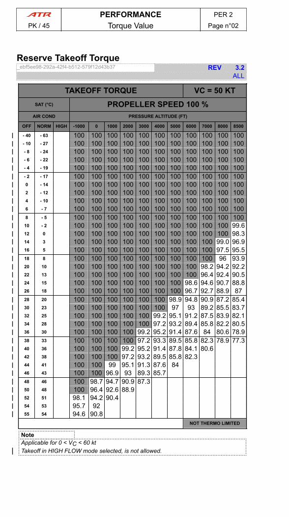
Reserve Takeoff Torque_ebf5ee98-292a-42f4-b512-579f12d43b37 REV 3.2
ALL
TAKEOFF TORQUE VC = 50 KTSAT (°C) PROPELLER SPEED 100 %
AIR COND PRESSURE ALTITUDE (FT)
OFF NORM HIGH -1000 0 1000 2000 3000 4000 5000 6000 7000 8000 8500
- 40 - 63 100 100 100 100 100 100 100 100 100 100 100- 10 - 27 100 100 100 100 100 100 100 100 100 100 100- 8 - 24 100 100 100 100 100 100 100 100 100 100 100- 6 - 22 100 100 100 100 100 100 100 100 100 100 100- 4 - 19 100 100 100 100 100 100 100 100 100 100 100- 2 - 17 100 100 100 100 100 100 100 100 100 100 1000 - 14 100 100 100 100 100 100 100 100 100 100 1002 - 12 100 100 100 100 100 100 100 100 100 100 1004 - 10 100 100 100 100 100 100 100 100 100 100 1006 - 7 100 100 100 100 100 100 100 100 100 100 1008 - 5 100 100 100 100 100 100 100 100 100 100 100
10 - 2 100 100 100 100 100 100 100 100 100 100 99.612 0 100 100 100 100 100 100 100 100 100 100 98.314 3 100 100 100 100 100 100 100 100 100 99.0 96.916 5 100 100 100 100 100 100 100 100 100 97.5 95.518 8 100 100 100 100 100 100 100 100 100 96 93.920 10 100 100 100 100 100 100 100 100 98.2 94.2 92.222 13 100 100 100 100 100 100 100 100 96.4 92.4 90.524 15 100 100 100 100 100 100 100 98.6 94.6 90.7 88.826 18 100 100 100 100 100 100 100 96.7 92.7 88.9 8728 20 100 100 100 100 100 100 98.9 94.8 90.9 87.2 85.430 23 100 100 100 100 100 100 97 93 89.2 85.5 83.732 25 100 100 100 100 100 99.2 95.1 91.2 87.5 83.9 82.134 28 100 100 100 100 100 97.2 93.2 89.4 85.8 82.2 80.536 30 100 100 100 100 99.2 95.2 91.4 87.6 84 80.6 78.938 33 100 100 100 100 97.2 93.3 89.5 85.8 82.3 78.9 77.340 36 100 100 100 99.2 95.2 91.4 87.8 84.1 80.642 38 100 100 100 97.2 93.2 89.5 85.8 82.344 41 100 100 99 95.1 91.3 87.6 8446 43 100 100 96.9 93 89.3 85.748 46 100 98.7 94.7 90.9 87.350 48 100 96.4 92.6 88.952 51 98.1 94.2 90.454 53 95.7 9255 54 94.6 90.8
NOT THERMO LIMITED
NoteApplicable for 0 < VC < 60 ktTakeoff in HIGH FLOW mode selected, is not allowed.
PERFORMANCE PER 2
PK / 45 Torque Value Page n°02
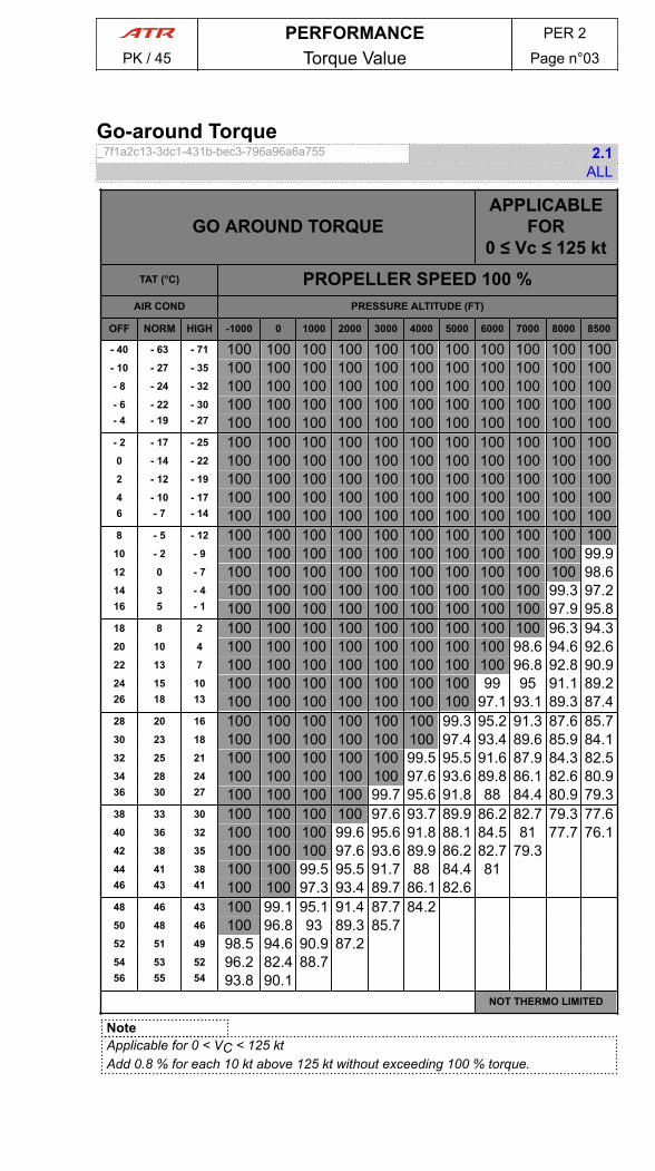
Go-around Torque_7f1a2c13-3dc1-431b-bec3-796a96a6a755 2.1
ALL
GO AROUND TORQUEAPPLICABLE
FOR0 ≤ Vc ≤ 125 kt
TAT (°C) PROPELLER SPEED 100 %AIR COND PRESSURE ALTITUDE (FT)
OFF NORM HIGH -1000 0 1000 2000 3000 4000 5000 6000 7000 8000 8500
- 40 - 63 - 71 100 100 100 100 100 100 100 100 100 100 100- 10 - 27 - 35 100 100 100 100 100 100 100 100 100 100 100- 8 - 24 - 32 100 100 100 100 100 100 100 100 100 100 100- 6 - 22 - 30 100 100 100 100 100 100 100 100 100 100 100- 4 - 19 - 27 100 100 100 100 100 100 100 100 100 100 100- 2 - 17 - 25 100 100 100 100 100 100 100 100 100 100 1000 - 14 - 22 100 100 100 100 100 100 100 100 100 100 1002 - 12 - 19 100 100 100 100 100 100 100 100 100 100 1004 - 10 - 17 100 100 100 100 100 100 100 100 100 100 1006 - 7 - 14 100 100 100 100 100 100 100 100 100 100 1008 - 5 - 12 100 100 100 100 100 100 100 100 100 100 100
10 - 2 - 9 100 100 100 100 100 100 100 100 100 100 99.912 0 - 7 100 100 100 100 100 100 100 100 100 100 98.614 3 - 4 100 100 100 100 100 100 100 100 100 99.3 97.216 5 - 1 100 100 100 100 100 100 100 100 100 97.9 95.818 8 2 100 100 100 100 100 100 100 100 100 96.3 94.320 10 4 100 100 100 100 100 100 100 100 98.6 94.6 92.622 13 7 100 100 100 100 100 100 100 100 96.8 92.8 90.924 15 10 100 100 100 100 100 100 100 99 95 91.1 89.226 18 13 100 100 100 100 100 100 100 97.1 93.1 89.3 87.428 20 16 100 100 100 100 100 100 99.3 95.2 91.3 87.6 85.730 23 18 100 100 100 100 100 100 97.4 93.4 89.6 85.9 84.132 25 21 100 100 100 100 100 99.5 95.5 91.6 87.9 84.3 82.534 28 24 100 100 100 100 100 97.6 93.6 89.8 86.1 82.6 80.936 30 27 100 100 100 100 99.7 95.6 91.8 88 84.4 80.9 79.338 33 30 100 100 100 100 97.6 93.7 89.9 86.2 82.7 79.3 77.640 36 32 100 100 100 99.6 95.6 91.8 88.1 84.5 81 77.7 76.142 38 35 100 100 100 97.6 93.6 89.9 86.2 82.7 79.344 41 38 100 100 99.5 95.5 91.7 88 84.4 8146 43 41 100 100 97.3 93.4 89.7 86.1 82.648 46 43 100 99.1 95.1 91.4 87.7 84.250 48 46 100 96.8 93 89.3 85.752 51 49 98.5 94.6 90.9 87.254 53 52 96.2 82.4 88.756 55 54 93.8 90.1
NOT THERMO LIMITED
NoteApplicable for 0 < VC < 125 ktAdd 0.8 % for each 10 kt above 125 kt without exceeding 100 % torque.
PERFORMANCE PER 2
PK / 45 Torque Value Page n°03

PAGE
INTENTIONALLY
LEFT BLANK
PERFORMANCE PER 2
PK / 45 Torque Value Page n°04
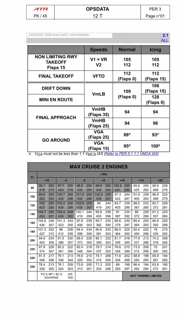
_34659325-7628-4cbb-bd03-1ad4c0b6fe9c 2.1ALL
Speeds Normal IcingNON LIMITING RWY
TAKEOFFFlaps 15
V1 = VRV2
105112
105112
FINAL TAKEOFF VFTO 112(Flaps 0)
112(Flaps 15)
DRIFT DOWNVmLB 109
(Flaps 0)
106(Flaps 15)
MINI EN ROUTE 128(Flaps 0)
FINAL APPROACH
VmHB(Flaps 35) 94 94
VmHB(Flaps 25) 94 96
GO AROUND
VGA(Flaps 25) 88a 93a
VGA(Flaps 15) 95a 100a
a VGA must not be less than 1.1 VMCA IAS (Refer to PER.5.1 1.1 VMCA IAS)
MAX CRUISE 2 ENGINES
FL∆ ISA
–10 –5 0 +5 +10 +15 +20
8096.7 250 97.7 250 98.8 250 99.9 250 100.9 250 95.8 245 90.5 239418 275 424 278 430 280 435 283 441 285 425 282 408 278
10099.6 250 100.7 250 101.8 250 102.9 250 97.3 244 91.9 239 86.9 233420 283 426 286 432 289 439 291 422 287 405 283 389 279
120102 250 103.2 250 103.8 250 99 244 93.7 239 88.5 233 83.7 228423 292 430 295 435 297 419 293 403 289 387 285 372 281
140104.7 250 104.4 249 100.1 244 95.6 239 91 234 86 228 81.2 223433 301 434 302 418 299 403 296 387 292 372 288 357 284
160104.6 248 101.3 244 97.6 239 93.7 235 89.6 230 85.4 225 80.9 220436 307 423 305 408 303 392 300 379 297 364 293 350 289
180101.3 242 98 238 94.4 234 90.6 230 86.5 225 82.4 220 78 215427 310 412 308 396 306 381 303 364 300 350 296 335 292
20094.6 234 91.5 230 88.4 226 85.1 222 81.7 218 77.9 213 74.2 208400 309 386 307 373 305 359 303 345 300 331 296 318 292
22087.9 226 85.2 222 82.4 218 79.7 214 76.6 210 73.5 206 70 201374 307 361 306 348 304 337 302 324 299 312 296 300 292
24081.5 217 79.1 213 76.6 210 74.1 206 71.6 202 68.8 198 65.9 194348 306 336 304 325 302 314 300 304 298 293 295 281 292
25078.4 213 76.1 209 73.8 205 71.3 202 69 198 66.4 194 63.8 190336 305 324 303 313 301 303 299 293 297 283 294 272 291TQ % NP = 82 %
KG/H/ENGIASTAS NOT THERMO LIMITED
OPSDATA PER 3
PK / 45 12 T Page n°01

_8bba19cf-9b80-479d-bab0-6e90acaa172a 3.1ALL
Speeds Normal IcingNON LIMITING RWY
TAKEOFFFlaps 15
V1 = VRV2
105112
105112
FINAL TAKEOFF VFTO 113(Flaps 0)
112(Flaps 15)
DRIFT DOWNVmLB 113
(Flaps 0)
111(Flaps 15)
MINI EN ROUTE 134(Flaps 0)
FINAL APPROACH
VmHB(Flaps 35) 94 96
VmHB(Flaps 25) 94 102
GO AROUND
VGA(Flaps 25) 92a 97a
VGA(Flaps 15) 100a 105a
a VGA must not be less than 1.1 VMCA IAS (Refer to PER.5.1 1.1 VMCA IAS)
MAX CRUISE 2 ENGINES
FL∆ ISA
–10 –5 0 +5 +10 +15 +20
8096.9 250 98 250 99.1 250 100.2 250 101.2 250 95.8 244 90.4 239419 275 425 278 431 280 436 283 442 285 425 282 408 277
10099.8 250 100.9 250 102 250 103.1 250 97.3 244 91.9 238 86.8 233421 283 427 286 433 289 439 291 422 287 405 283 389 279
120102.2 250 103.5 250 103.8 249 99 244 93.6 238 88.4 232 83.7 227424 292 431 295 435 296 419 293 402 289 387 285 372 281
140105 250 104.4 248 100.1 244 95.5 239 90.9 233 86 228 81.2 222434 301 434 302 417 299 402 295 387 292 372 288 357 283
160104.6 247 101.3 243 97.6 239 93.7 234 89.6 230 85.3 225 80.8 219436 306 423 305 408 302 392 300 379 296 364 293 350 288
180101.2 242 97.9 238 94.3 234 90.5 229 86.4 224 82.3 219 77.9 214426 309 412 307 396 305 381 302 364 299 350 295 335 290
20094.4 234 91.3 230 88.3 226 85 221 81.6 217 77.8 212 74.1 207400 308 385 306 372 304 358 302 345 299 330 295 318 291
22087.8 225 85.1 221 82.2 217 79.5 213 76.4 209 73.3 205 69.9 200373 307 360 305 348 303 336 300 324 298 311 2951 299 291
24081.3 216 78.9 212 76.4 209 73.9 205 71.4 201 68.6 197 65.7 193347 304 335 303 324 301 313 298 303 296 292 293 281 289
25078.2 212 75.8 208 73.6 204 71.1 201 68.8 197 66.3 193 63.6 189335 303 323 301 313 299 302 297 292 295 283 292 272 288TQ % NP = 82 %
KG/H/ENGIASTAS NOT THERMO LIMITED
OPSDATA PER 3
PK / 45 13 T Page n°02

_3ce7ceaf-4d98-4c72-b85e-4e53d26b52b7 3.1ALL
Speeds Normal IcingNON LIMITING RWY
TAKEOFFFlaps 15
V1 = VRV2
105112
105112
FINAL TAKEOFF VFTO 117(Flaps 0)
112(Flaps 15)
DRIFT DOWNVmLB 117
(Flaps 0)
117(Flaps 15)
MINI EN ROUTE 139(Flaps 0)
FINAL APPROACH
VmHB(Flaps 35) 94 100
VmHB(Flaps 25) 95 105
GO AROUND
VGA(Flaps 25) 96a 101a
VGA(Flaps 15) 104a 109a
a VGA must not be less than 1.1 VMCA IAS (Refer to PER.5.1 1.1 VMCA IAS)
MAX CRUISE 2 ENGINES
FL∆ ISA
–10 –5 0 +5 +10 +15 +20
8097.2 250 98.3 250 99.4 250 100.5 250 101.3 250 95.7 244 90.4 238420 275 426 278 432 280 437 283 442 285 425 281 408 277
100100.1 250 101.3 250 102.4 250 103.1 250 97.2 244 91.9 238 86.8 232422 283 428 286 434 289 439 291 421 287 405 282 389 278
120102.6 250 103.8 250 103.8 249 98.9 244 93.6 238 88.4 232 83.6 227425 292 432 295 435 296 419 292 402 288 386 284 372 280
140105.4 250 104.3 248 100 243 95.5 238 90.9 233 85.9 227 81.1 221436 301 434 301 417 298 402 295 387 291 372 287 357 282
160104.6 247 101.2 243 97.6 238 93.6 234 89.6 229 85.3 224 80.8 218436 306 422 304 408 302 392 299 379 296 364 292 350 287
180101.1 241 97.8 237 94.2 233 90.4 228 86.3 223 82.2 218 77.8 213426 309 411 307 395 304 381 301 364 298 350 294 335 289
20094.3 233 91.2 229 88.2 225 84.8 220 81.4 216 77.7 211 74 206399 307 385 305 372 303 358 300 344 297 330 294 317 289
22087.6 224 84.9 220 82.1 216 79.3 212 76.3 208 73.2 204 69.7 199372 305 359 303 347 301 335 299 323 296 311 293 299 289
24081.1 215 78.6 211 76.2 207 73.7 203 71.2 200 68.4 195 65.5 191347 303 335 301 323 299 313 296 303 294 291 291 280 287
25077.9 210 75.6 206 73.2 203 70.9 199 68.5 195 66 191 63.3 186334 301 322 299 312 297 302 295 292 292 282 289 271 285TQ % NP = 82 %
KG /H/ENGIASTAS NOT THERMO LIMITED
OPSDATA PER 3
PK / 45 14 T Page n°03
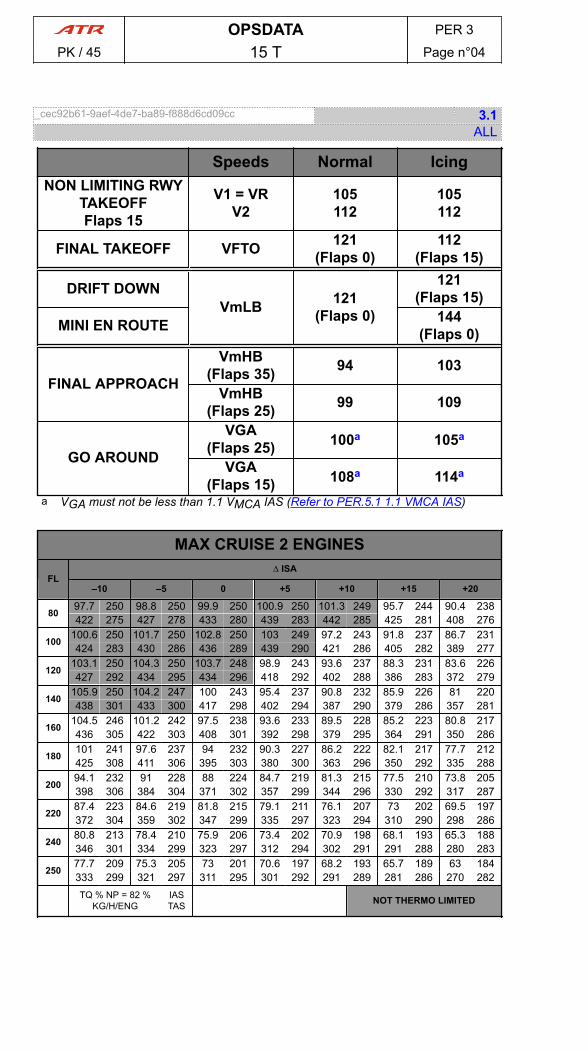
_cec92b61-9aef-4de7-ba89-f888d6cd09cc 3.1ALL
Speeds Normal IcingNON LIMITING RWY
TAKEOFFFlaps 15
V1 = VRV2
105112
105112
FINAL TAKEOFF VFTO 121(Flaps 0)
112(Flaps 15)
DRIFT DOWNVmLB 121
(Flaps 0)
121(Flaps 15)
MINI EN ROUTE 144(Flaps 0)
FINAL APPROACH
VmHB(Flaps 35) 94 103
VmHB(Flaps 25) 99 109
GO AROUND
VGA(Flaps 25) 100a 105a
VGA(Flaps 15) 108a 114a
a VGA must not be less than 1.1 VMCA IAS (Refer to PER.5.1 1.1 VMCA IAS)
MAX CRUISE 2 ENGINES
FL∆ ISA
–10 –5 0 +5 +10 +15 +20
8097.7 250 98.8 250 99.9 250 100.9 250 101.3 249 95.7 244 90.4 238422 275 427 278 433 280 439 283 442 285 425 281 408 276
100100.6 250 101.7 250 102.8 250 103 249 97.2 243 91.8 237 86.7 231424 283 430 286 436 289 439 290 421 286 405 282 389 277
120103.1 250 104.3 250 103.7 248 98.9 243 93.6 237 88.3 231 83.6 226427 292 434 295 434 296 418 292 402 288 386 283 372 279
140105.9 250 104.2 247 100 243 95.4 237 90.8 232 85.9 226 81 220438 301 433 300 417 298 402 294 387 290 379 286 357 281
160104.5 246 101.2 242 97.5 238 93.6 233 89.5 228 85.2 223 80.8 217436 305 422 303 408 301 392 298 379 295 364 291 350 286
180101 241 97.6 237 94 232 90.3 227 86.2 222 82.1 217 77.7 212425 308 411 306 395 303 380 300 363 296 350 292 335 288
20094.1 232 91 228 88 224 84.7 219 81.3 215 77.5 210 73.8 205398 306 384 304 371 302 357 299 344 296 330 292 317 287
22087.4 223 84.6 219 81.8 215 79.1 211 76.1 207 73 202 69.5 197372 304 359 302 347 299 335 297 323 294 310 290 298 286
24080.8 213 78.4 210 75.9 206 73.4 202 70.9 198 68.1 193 65.3 188346 301 334 299 323 297 312 294 302 291 291 288 280 283
25077.7 209 75.3 205 73 201 70.6 197 68.2 193 65.7 189 63 184333 299 321 297 311 295 301 292 291 289 281 286 270 282TQ % NP = 82 %
KG/H/ENGIASTAS NOT THERMO LIMITED
OPSDATA PER 3
PK / 45 15 T Page n°04
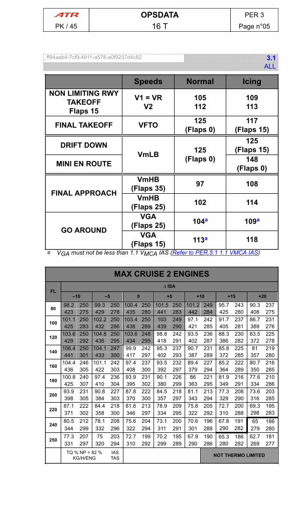
_ff94aab4-7cf9-4911-a578-a0f9237d4c82 3.1ALL
Speeds Normal IcingNON LIMITING RWY
TAKEOFFFlaps 15
V1 = VRV2
105112
109113
FINAL TAKEOFF VFTO 125(Flaps 0)
117(Flaps 15)
DRIFT DOWNVmLB 125
(Flaps 0)
125(Flaps 15)
MINI EN ROUTE 148(Flaps 0)
FINAL APPROACH
VmHB(Flaps 35) 97 108
VmHB(Flaps 25) 102 114
GO AROUND
VGA(Flaps 25) 104a 109a
VGA(Flaps 15) 113a 118
a VGA must not be less than 1.1 VMCA IAS (Refer to PER.5.1 1.1 VMCA IAS)
MAX CRUISE 2 ENGINES
FL∆ ISA
–10 –5 0 +5 +10 +15 +20
8098.2 250 99.3 250 100.4 250 101.5 250 101.2 249 95.7 243 90.3 237423 275 429 278 435 280 441 283 442 284 425 280 408 275
100101.1 250 102.2 250 103.4 250 103 249 97.1 242 91.7 237 86.7 231425 283 432 286 438 289 439 290 421 285 405 281 389 276
120103.6 250 104.8 250 103.6 248 98.8 242 93.5 236 88.3 230 83.5 225429 292 436 295 434 295 418 291 402 287 386 282 372 278
140106.4 250 104.1 247 99.9 242 95.3 237 90.7 231 85.8 225 81 219441 301 433 300 417 297 402 293 387 289 372 285 357 280
160104.4 246 101.1 242 97.4 237 93.5 232 89.4 227 85.2 222 80.7 216436 305 422 303 408 300 392 297 379 294 364 289 350 285
180100.8 240 97.4 236 93.9 231 90.1 226 86 221 81.9 216 77.6 210425 307 410 304 395 302 380 299 363 295 349 291 334 286
20093.9 231 90.8 227 87.8 222 84.5 218 81.1 213 77.3 208 73.6 203398 305 384 303 370 300 357 297 343 294 329 290 316 285
22087.1 222 84.4 218 81.6 213 78.9 209 75.8 205 72.7 200 69.3 195371 302 358 300 346 297 334 295 322 292 310 288 298 283
24080.5 212 78.1 208 75.6 204 73.1 200 70.6 196 67.8 191 65 186344 299 332 296 322 294 311 291 301 288 290 282 279 280
25077.3 207 75 203 72.7 199 70.2 195 67.9 190 65.3 186 62.7 181331 297 320 294 310 292 299 289 290 286 280 282 269 277TQ % NP = 82 %
KG/H/ENGIASTAS NOT THERMO LIMITED
OPSDATA PER 3
PK / 45 16 T Page n°05
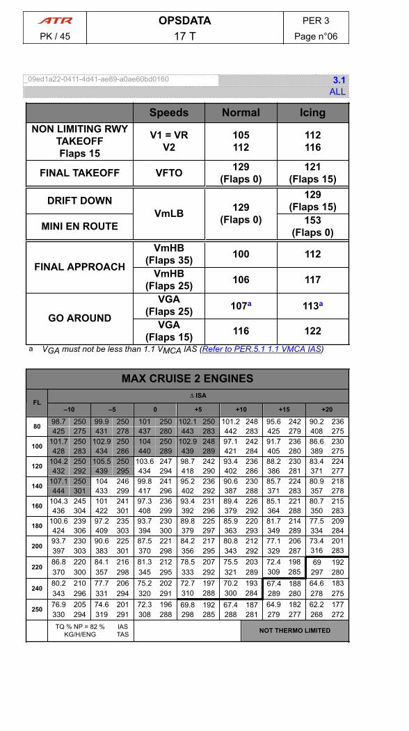
_09ed1a22-0411-4d41-ae89-a0ae60bd0160 3.1ALL
Speeds Normal IcingNON LIMITING RWY
TAKEOFFFlaps 15
V1 = VRV2
105112
112116
FINAL TAKEOFF VFTO 129(Flaps 0)
121(Flaps 15)
DRIFT DOWNVmLB 129
(Flaps 0)
129(Flaps 15)
MINI EN ROUTE 153(Flaps 0)
FINAL APPROACH
VmHB(Flaps 35) 100 112
VmHB(Flaps 25) 106 117
GO AROUND
VGA(Flaps 25) 107a 113a
VGA(Flaps 15) 116 122
a VGA must not be less than 1.1 VMCA IAS (Refer to PER.5.1 1.1 VMCA IAS)
MAX CRUISE 2 ENGINES
FL∆ ISA
–10 –5 0 +5 +10 +15 +20
8098.7 250 99.9 250 101 250 102.1 250 101.2 248 95.6 242 90.2 236425 275 431 278 437 280 443 283 442 283 425 279 408 275
100101.7 250 102.9 250 104 250 102.9 248 97.1 242 91.7 236 86.6 230428 283 434 286 440 289 439 289 421 284 405 280 389 275
120104.2 250 105.5 250 103.6 247 98.7 242 93.4 236 88.2 230 83.4 224432 292 439 295 434 294 418 290 402 286 386 281 371 277
140107.1 250 104 246 99.8 241 95.2 236 90.6 230 85.7 224 80.9 218444 301 433 299 417 296 402 292 387 288 371 283 357 278
160104.3 245 101 241 97.3 236 93.4 231 89.4 226 85.1 221 80.7 215436 304 422 301 408 299 392 296 379 292 364 288 350 283
180100.6 239 97.2 235 93.7 230 89.8 225 85.9 220 81.7 214 77.5 209424 306 409 303 394 300 379 297 363 293 349 289 334 284
20093.7 230 90.6 225 87.5 221 84.2 217 80.8 212 77.1 206 73.4 201397 303 383 301 370 298 356 295 343 292 329 287 316 283
22086.8 220 84.1 216 81.3 212 78.5 207 75.5 203 72.4 198 69 192370 300 357 298 345 295 333 292 321 289 309 285 297 280
24080.2 210 77.7 206 75.2 202 72.7 197 70.2 193 67.4 188 64.6 183343 296 331 294 320 291 310 288 300 284 289 280 278 275
25076.9 205 74.6 201 72.3 196 69.8 192 67.4 187 64.9 182 62.2 177330 294 319 291 308 288 298 285 288 281 279 277 268 272TQ % NP = 82 %
KG/H/ENGIASTAS NOT THERMO LIMITED
OPSDATA PER 3
PK / 45 17 T Page n°06
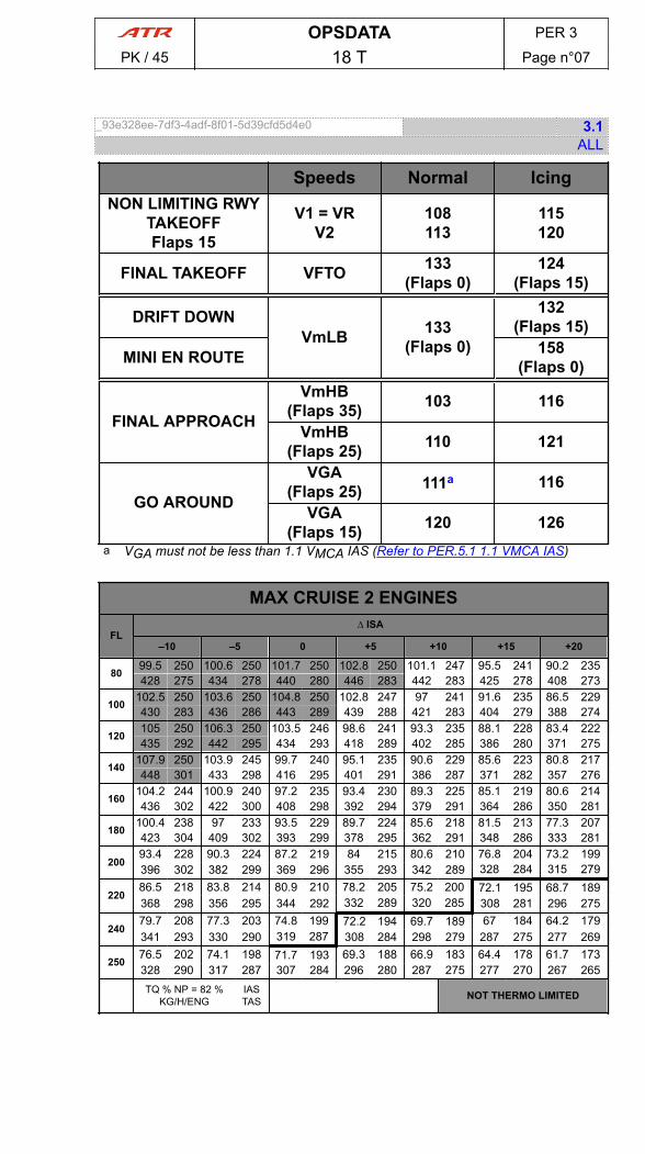
_93e328ee-7df3-4adf-8f01-5d39cfd5d4e0 3.1ALL
Speeds Normal IcingNON LIMITING RWY
TAKEOFFFlaps 15
V1 = VRV2
108113
115120
FINAL TAKEOFF VFTO 133(Flaps 0)
124(Flaps 15)
DRIFT DOWNVmLB 133
(Flaps 0)
132(Flaps 15)
MINI EN ROUTE 158(Flaps 0)
FINAL APPROACH
VmHB(Flaps 35) 103 116
VmHB(Flaps 25) 110 121
GO AROUND
VGA(Flaps 25) 111a 116
VGA(Flaps 15) 120 126
a VGA must not be less than 1.1 VMCA IAS (Refer to PER.5.1 1.1 VMCA IAS)
MAX CRUISE 2 ENGINES
FL∆ ISA
–10 –5 0 +5 +10 +15 +20
8099.5 250 100.6 250 101.7 250 102.8 250 101.1 247 95.5 241 90.2 235428 275 434 278 440 280 446 283 442 283 425 278 408 273
100102.5 250 103.6 250 104.8 250 102.8 247 97 241 91.6 235 86.5 229430 283 436 286 443 289 439 288 421 283 404 279 388 274
120105 250 106.3 250 103.5 246 98.6 241 93.3 235 88.1 228 83.4 222435 292 442 295 434 293 418 289 402 285 386 280 371 275
140107.9 250 103.9 245 99.7 240 95.1 235 90.6 229 85.6 223 80.8 217448 301 433 298 416 295 401 291 386 287 371 282 357 276
160104.2 244 100.9 240 97.2 235 93.4 230 89.3 225 85.1 219 80.6 214436 302 422 300 408 298 392 294 379 291 364 286 350 281
180100.4 238 97 233 93.5 229 89.7 224 85.6 218 81.5 213 77.3 207423 304 409 302 393 299 378 295 362 291 348 286 333 281
20093.4 228 90.3 224 87.2 219 84 215 80.6 210 76.8 204 73.2 199396 302 382 299 369 296 355 293 342 289 328 284 315 279
22086.5 218 83.8 214 80.9 210 78.2 205 75.2 200 72.1 195 68.7 189368 298 356 295 344 292 332 289 320 285 308 281 296 275
24079.7 208 77.3 203 74.8 199 72.2 194 69.7 189 67 184 64.2 179341 293 330 290 319 287 308 284 298 279 287 275 277 269
25076.5 202 74.1 198 71.7 193 69.3 188 66.9 183 64.4 178 61.7 173328 290 317 287 307 284 296 280 287 275 277 270 267 265TQ % NP = 82 %
KG/H/ENGIASTAS NOT THERMO LIMITED
OPSDATA PER 3
PK / 45 18 T Page n°07

_d8cb7ccc-8d2f-4d36-b436-1d7c43a3ae0f 3.1ALL
Speeds Normal IcingNON LIMITING RWY
TAKEOFFFlaps 15
V1 = VRV2
110115
118122
FINAL TAKEOFF VFTO 135(Flaps 0)
127(Flaps 15)
DRIFT DOWNVmLB 135
(Flaps 0)
135(Flaps 15)
MINI EN ROUTE 160(Flaps 0)
FINAL APPROACH
VmHB(Flaps 35) 104 117
VmHB(Flaps 25) 112 124
GO AROUND
VGA(Flaps 25) 113a 118
VGA(Flaps 15) 122 128
a VGA must not be less than 1.1 VMCA IAS (Refer to PER.5.1 1.1 VMCA IAS)
MAX CRUISE 2 ENGINES
FL∆ ISA
–10 –5 0 +5 +10 +15 +20
8099.9 250 101 250 102.2 250 103.3 250 101 247 95.5 241 90.1 235429 275 435 278 441 280 447 283 442 282 425 277 408 273
100102.9 250 104.1 250 105.2 250 102.8 247 96.9 240 91.5 234 86.4 228432 283 438 286 445 289 439 288 421 283 404 278 388 273
120105.5 250 106.1 250 103.4 246 98.6 240 93.3 234 88.1 228 83.3 222437 292 444 295 434 292 418 288 402 284 386 279 371 274
140108 250 103.8 245 99.6 240 95 234 90.5 228 85.5 222 80.7 216449 300 432 297 416 294 401 290 386 286 371 281 356 275
160104.1 243 100.8 239 97.2 235 93.3 230 89.2 224 85 219 80.5 213435 302 422 299 408 297 392 294 379 290 364 285 350 280
180100.2 237 96.9 233 93.3 228 89.5 223 85.5 217 81.4 212 77.2 206423 303 408 301 393 298 378 294 362 290 348 285 333 280
20093.2 227 90.1 223 87.1 218 83.8 214 80.4 208 76.7 203 73 197395 300 381 298 368 295 355 291 341 287 328 282 315 277
22086.3 217 83.5 213 80.7 208 78 204 75 199 71.9 193 68.5 187368 296 355 294 343 290 331 287 320 283 307 278 296 272
24079.5 206 77 202 74.5 197 71.9 192 69.4 187 66.7 182 63.9 176340 291 329 288 318 285 307 281 297 276 287 271 276 265
25076.2 200 73.7 196 71.4 191 68.9 186 66.5 181 64.1 175 61.3 169327 288 316 284 305 281 295 276 286 271 276 266 266 259TQ % NP = 82 %
KG/H/ENGIASTAS NOT THERMO LIMITED
OPSDATA PER 3
PK / 45 18.6 T Page n°08
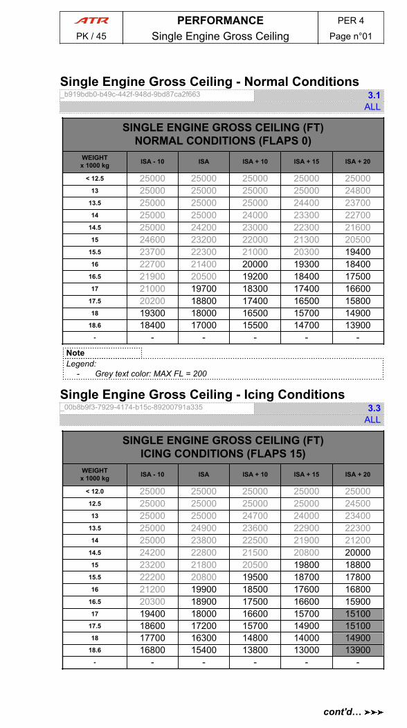
Single Engine Gross Ceiling - Normal Conditions_b919bdb0-b49c-442f-948d-9bd87ca2f663 3.1
ALL
SINGLE ENGINE GROSS CEILING (FT)NORMAL CONDITIONS (FLAPS 0)
WEIGHTx 1000 kg ISA - 10 ISA ISA + 10 ISA + 15 ISA + 20
< 12.5 25000 25000 25000 25000 2500013 25000 25000 25000 25000 24800
13.5 25000 25000 25000 24400 2370014 25000 25000 24000 23300 22700
14.5 25000 24200 23000 22300 2160015 24600 23200 22000 21300 20500
15.5 23700 22300 21000 20300 1940016 22700 21400 20000 19300 18400
16.5 21900 20500 19200 18400 1750017 21000 19700 18300 17400 16600
17.5 20200 18800 17400 16500 1580018 19300 18000 16500 15700 14900
18.6 18400 17000 15500 14700 13900- - - - - -
NoteLegend:
- Grey text color: MAX FL = 200
Single Engine Gross Ceiling - Icing Conditions_00b8b9f3-7929-4174-b15c-89200791a335 3.3
ALL
SINGLE ENGINE GROSS CEILING (FT)ICING CONDITIONS (FLAPS 15)
WEIGHTx 1000 kg ISA - 10 ISA ISA + 10 ISA + 15 ISA + 20
< 12.0 25000 25000 25000 25000 2500012.5 25000 25000 25000 25000 2450013 25000 25000 24700 24000 23400
13.5 25000 24900 23600 22900 2230014 25000 23800 22500 21900 21200
14.5 24200 22800 21500 20800 2000015 23200 21800 20500 19800 18800
15.5 22200 20800 19500 18700 1780016 21200 19900 18500 17600 16800
16.5 20300 18900 17500 16600 1590017 19400 18000 16600 15700 15100
17.5 18600 17200 15700 14900 1510018 17700 16300 14800 14000 14900
18.6 16800 15400 13800 13000 13900- - - - - -
PERFORMANCE PER 4
PK / 45 Single Engine Gross Ceiling Page n°01
cont'd…
NoteLegend:
- Grey background: icing conditions do not exist- Grey text color: MAX FL = 200
PERFORMANCE PER 4
PK / 45 Single Engine Gross Ceiling Page n°02
cont'd…
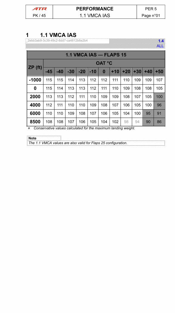
1 1.1 VMCA IAS_2ebb3ab9-3c39-49c2-8dd7-ca4812b6e2b4 1.4
ALL
1.1 VMCA IAS — FLAPS 15
ZP (ft)OAT °C
-45 -40 -30 -20 -10 0 +10 +20 +30 +40 +50
-1000 115 115 114 113 112 112 111 110 109 109 107
0 115 114 113 113 112 111 110 109 108 108 105
2000 113 113 112 111 110 109 109 108 107 105 100
4000 112 111 110 110 109 108 107 106 105 100 96
6000 110 110 109 108 107 106 105 104 100 95 91
8500 108 108 107 106 105 104 102 98 94 90 86a Conservative values calculated for the maximum landing weight.
NoteThe 1.1 VMCA values are also valid for Flaps 25 configuration.
PERFORMANCE PER 5
PK / 45 1.1 VMCA IAS Page n°01
PAGE
INTENTIONALLY
LEFT BLANK
PERFORMANCE PER 5
PK / 45 1.1 VMCA IAS Page n°02

1 LDTA tables - Sea Level_7723c2fe-2941-43e6-b1a9-eac7bc670fb3 MOVED 0.11
ALLUse LDTA tables if in-flight landing distance assessment based on LDTA is required bynational regulation.In case of failure impacting landing performance, use Actual Landing Distancemultiplied by landing distance penalty coefficient (Refer to PER.6.1.2 Actual LandingDistance - Sea Level).In following tables, LDTA values are conservative, refer to FCOM/PER/LDTA (Refer toPER.10.1.4.1 Introduction) or use FOS/SPS for more accurate values.
NORMAL CONDITIONS - FLAPS 35
1.15 x LDTA (m)
Weight (1 000 kg) →12 13 14 15 16 17 18 18.6
RWYCC ↓
6 - DRY 778 778 778 789 822 860 900 9235 - GOOD 864 869 874 891 931 975 1018 1041
4 - GOOD to MEDIUM 993 1004 1015 1037 1082 1130 1176 12013 - MEDIUM 1049 1063 1077 1103 1152 1204 1254 1281
2 - MEDIUM to POOR 1056 1072 1088 1116 1170 1228 1284 13161- POOR 1311 1338 1364 1404 1468 1535 1600 1637
ICING CONDITIONS - FLAPS 35
1.15 x LDTA (m)
Weight (1 000 kg) →12 13 14 15 16 17 18 18.6
RWYCC ↓
6 - DRY 888 888 888 902 941 987 1034 10615 - GOOD 988 994 1001 1021 1068 1120 1171 1199
4 - GOOD to MEDIUM 1118 1131 1143 1169 1221 1277 1331 13603 - MEDIUM 1164 1180 1197 1227 1283 1343 1401 1433
2 - MEDIUM to POOR 1190 1208 1226 1259 1321 1388 1453 14891- POOR 1433 1463 1493 1538 1611 1687 1761 1802
LDTA CORRECTIONS
Airportelevation
DeltaISA Wind VAPP
increaseReverse
use
Runwayslope
per 1 000 ftabove sea
level
per+5 °C
Tailwindper 5 kt
Headwindper 5 kt
per 5 kt(max 15 kt) per -1 %
6 - DRY
+5% +3%
+13%
-4%
-3% +3%
5 - GOOD +16%
-4% +6%4 - GOOD to MEDIUM +16% +12%
3 - MEDIUM +18% (max +36%)
2 - MEDIUM to POOR +20%
1- POOR +25% -10% +19%
To take credit of uphill runway slope, temperature below ISA, Airport elevation belowsea level corrections, refer to FCOM/PER/LDTA (Refer to PER.10.1.4.1 Introduction).Note
- Use of reverse is not recommended in case of landing with one engineinoperative on contaminated runways.
- For a damp runway, use “5-GOOD” performance.
PERFORMANCE PER 6
PK / 45 Landing Page n°01
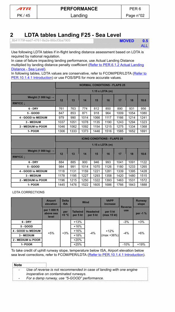
2 LDTA tables Landing F25 - Sea Level_8b41179f-ead7-4761-8e2e-86bcf3ba7905 MOVED 0.5
ALLUse following LDTA tables if in-flight landing distance assessment based on LDTA isrequired by national regulation.In case of failure impacting landing performance, use Actual Landing Distancemultiplied by landing distance penalty coefficient (Refer to PER.6.1.2 Actual LandingDistance - Sea Level).In following tables, LDTA values are conservative, refer to FCOM/PER/LDTA (Refer toPER.10.1.4.1 Introduction) or use FOS/SPS for more accurate values.
NORMAL CONDITIONS - FLAPS 25
1.15 x LDTA (m)
Weight (1 000 kg) →12 13 14 15 16 17 18 18.6
RWYCC ↓
6 - DRY 761 763 774 812 850 890 931 9565 - GOOD 847 853 871 918 964 1009 1054 1080
4 - GOOD to MEDIUM 979 990 1014 1066 1117 1166 1214 12413 - MEDIUM 1037 1051 1078 1135 1190 1243 1294 1323
2 - MEDIUM to POOR 1046 1062 1092 1154 1215 1275 1334 13681- POOR 1306 1333 1373 1446 1516 1585 1652 1691
ICING CONDITIONS - FLAPS 25
1.15 x LDTA (m)
Weight (1 000 kg) →12 13 14 15 16 17 18 18.6
RWYCC ↓
6 - DRY 884 885 900 946 993 1041 1091 11225 - GOOD 984 991 1014 1070 1126 1180 1233 1265
4 - GOOD to MEDIUM 1118 1131 1159 1221 1281 1339 1395 14283 - MEDIUM 1178 1195 1227 1293 1358 1420 1480 1515
2 - MEDIUM to POOR 1196 1215 1250 1322 1393 1463 1531 15721- POOR 1445 1476 1522 1605 1686 1766 1843 1888
LDTA CORRECTIONS
Airportelevation
DeltaISA Wind VAPP
increaseReverse
use
Runwayslope
per 1 000 ftabove sea
level
per+5 °C
Tailwindper 5 kt
Headwindper 5 kt
per 5 kt(max 15 kt) per -1 %
6 - DRY
+5% +3%
+13%
-4%
-3% +3%5 - GOOD +16%
-4% +6%4 - GOOD to MEDIUM +16% +12%
3 - MEDIUM +18% (max +36%)2 - MEDIUM to POOR +20%
1- POOR +25% -10% +19%
To take credit of uphill runway slope, temperature below ISA, Airport elevation belowsea level corrections, refer to FCOM/PER/LDTA (Refer to PER.10.1.4.1 Introduction).
Note- Use of reverse is not recommended in case of landing with one engine
inoperative on contaminated runways.- For a damp runway, use “5-GOOD” performance.
PERFORMANCE PER 6
PK / 45 Landing Page n°02
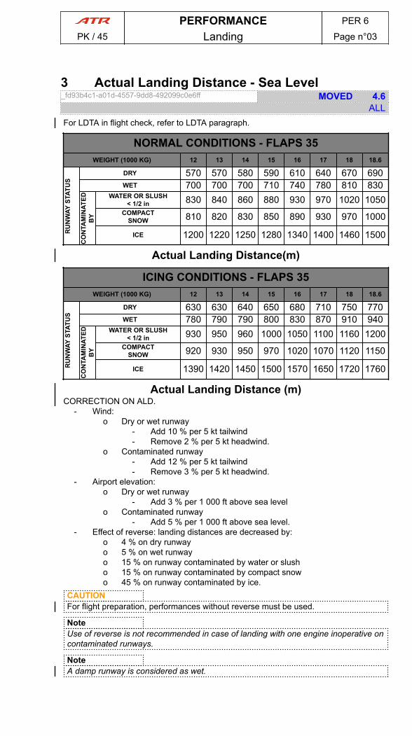
3 Actual Landing Distance - Sea Level_fd93b4c1-a01d-4557-9dd8-492099c0e6ff MOVED 4.6
ALLFor LDTA in flight check, refer to LDTA paragraph.
NORMAL CONDITIONS - FLAPS 35WEIGHT (1000 KG) 12 13 14 15 16 17 18 18.6
RU
NW
AY S
TATU
S
DRY 570 570 580 590 610 640 670 690WET 700 700 700 710 740 780 810 830
CO
NTA
MIN
ATED
BY
WATER OR SLUSH< 1/2 in 830 840 860 880 930 970 1020 1050
COMPACTSNOW 810 820 830 850 890 930 970 1000
ICE 1200 1220 1250 1280 1340 1400 1460 1500
Actual Landing Distance(m)
ICING CONDITIONS - FLAPS 35WEIGHT (1000 KG) 12 13 14 15 16 17 18 18.6
RU
NW
AY S
TATU
S
DRY 630 630 640 650 680 710 750 770WET 780 790 790 800 830 870 910 940
CO
NTA
MIN
ATED
BY
WATER OR SLUSH< 1/2 in 930 950 960 1000 1050 1100 1160 1200
COMPACTSNOW 920 930 950 970 1020 1070 1120 1150
ICE 1390 1420 1450 1500 1570 1650 1720 1760
Actual Landing Distance (m)CORRECTION ON ALD.
- Wind:o Dry or wet runway
- Add 10 % per 5 kt tailwind- Remove 2 % per 5 kt headwind.
o Contaminated runway- Add 12 % per 5 kt tailwind- Remove 3 % per 5 kt headwind.
- Airport elevation:o Dry or wet runway
- Add 3 % per 1 000 ft above sea levelo Contaminated runway
- Add 5 % per 1 000 ft above sea level.- Effect of reverse: landing distances are decreased by:
o 4 % on dry runwayo 5 % on wet runwayo 15 % on runway contaminated by water or slusho 15 % on runway contaminated by compact snowo 45 % on runway contaminated by ice.
CAUTIONFor flight preparation, performances without reverse must be used.
NoteUse of reverse is not recommended in case of landing with one engine inoperative oncontaminated runways.
NoteA damp runway is considered as wet.
PERFORMANCE PER 6
PK / 45 Landing Page n°03
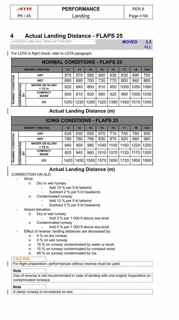
4 Actual Landing Distance - FLAPS 25_4ed90d8c-c28c-424c-938d-e6f77490a991 MOVED 2.5
ALLFor LDTA in flight check, refer to LDTA paragraph.
NORMAL CONDITIONS - FLAPS 25WEIGHT (1000 KG) 12 13 14 15 16 17 18 18.6
RU
NW
AY C
ON
DIT
ION DRY 570 570 580 600 630 630 690 700
WET 690 690 700 730 770 800 840 860
CO
NTA
MIN
ATED
BY
WATER OR SLUSH< 1/2 in 820 840 860 910 950 1000 1050 1080
COMPACTSNOW 800 810 830 880 920 960 1000 1030
ICE 1200 1230 1260 1320 1380 1450 1510 1540
Actual Landing Distance (m)
ICING CONDITIONS - FLAPS 25WEIGHT (1000 KG) 12 13 14 15 16 17 18 18.6
RU
NW
AY C
ON
DIT
ION DRY 630 630 650 670 710 740 780 800
WET 780 780 790 830 870 920 960 980
CO
NTA
MIN
ATED
BY
WATER OR SLUSH< 1/2 in 940 950 980 1040 1100 1160 1220 1250
COMPACTSNOW 920 940 960 1010 1070 1120 1170 1200
ICE 1420 1450 1500 1570 1650 1720 1800 1850
Actual Landing Distance (m)CORRECTION ON ALD
- Wind:o Dry or wet runway
- Add 10 % per 5 kt tailwind- Subtract 2 % per 5 kt headwind.
o Contaminated runway- Add 12 % per 5 kt tailwind- Subtract 3 % per 5 kt headwind.
- Airport elevation:o Dry or wet runway
- Add 3 % per 1 000 ft above sea levelo Contaminated runway
- Add 5 % per 1 000 ft above sea level.- Effect of reverse: landing distances are decreased by:
o 4 % on dry runwayo 5 % on wet runwayo 15 % on runway contaminated by water or slusho 15 % on runway contaminated by compact snowo 45 % on runway contaminated by ice.
CAUTIONFor flight preparation, performances without reverse must be used.
NoteUse of reverse is not recommended in case of landing with one engine inoperative oncontaminated runways.
NoteA damp runway is considered as wet.
PERFORMANCE PER 6
PK / 45 Landing Page n°04
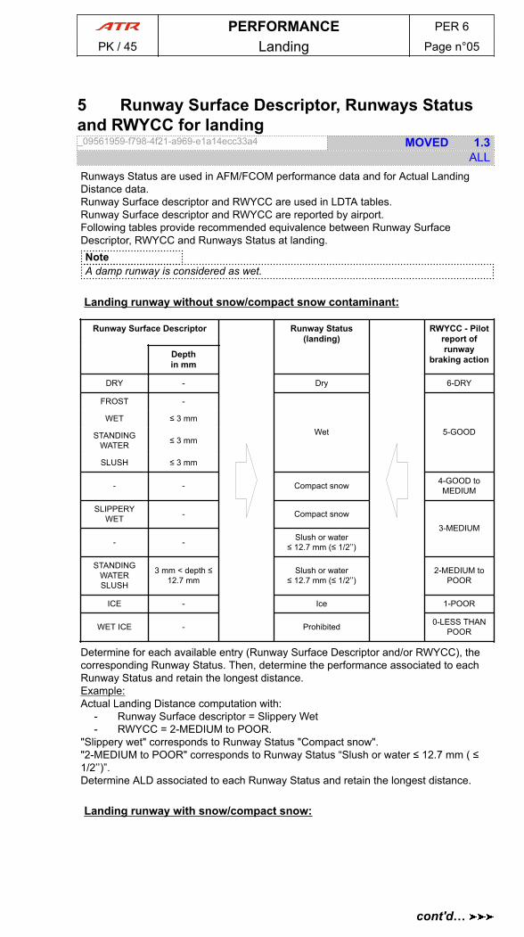
5 Runway Surface Descriptor, Runways Statusand RWYCC for landing_09561959-f798-4f21-a969-e1a14ecc33a4 MOVED 1.3
ALLRunways Status are used in AFM/FCOM performance data and for Actual LandingDistance data.Runway Surface descriptor and RWYCC are used in LDTA tables.Runway Surface descriptor and RWYCC are reported by airport.Following tables provide recommended equivalence between Runway SurfaceDescriptor, RWYCC and Runways Status at landing.NoteA damp runway is considered as wet.
Landing runway without snow/compact snow contaminant:
Runway Surface Descriptor Runway Status(landing)
RWYCC - Pilotreport ofrunway
braking actionDepthin mm
DRY - Dry 6-DRY
FROST -
Wet 5-GOODWET ≤ 3 mm
STANDINGWATER ≤ 3 mm
SLUSH ≤ 3 mm
- - Compact snow 4-GOOD toMEDIUM
SLIPPERYWET - Compact snow
3-MEDIUM
- - Slush or water≤ 12.7 mm (≤ 1/2’’)
STANDINGWATERSLUSH
3 mm < depth ≤12.7 mm
Slush or water≤ 12.7 mm (≤ 1/2’’)
2-MEDIUM toPOOR
ICE - Ice 1-POOR
WET ICE - Prohibited 0-LESS THANPOOR
Determine for each available entry (Runway Surface Descriptor and/or RWYCC), thecorresponding Runway Status. Then, determine the performance associated to eachRunway Status and retain the longest distance.Example:Actual Landing Distance computation with:
- Runway Surface descriptor = Slippery Wet- RWYCC = 2-MEDIUM to POOR.
"Slippery wet" corresponds to Runway Status "Compact snow"."2-MEDIUM to POOR" corresponds to Runway Status “Slush or water ≤ 12.7 mm ( ≤1/2’’)”.Determine ALD associated to each Runway Status and retain the longest distance.
Landing runway with snow/compact snow:
PERFORMANCE PER 6
PK / 45 Landing Page n°05
cont'd…

Runway Surface Descriptor Runway Status(landing)
RWYCC - Pilotreport of
runway brakingactionDepth
in mm
DRY SNOW ≤ 3 mmWet 5-GOOD
WET SNOW ≤ 3 mm
COMPACTSNOW
(OAT ≤ -15°C)- Compact snow 4-GOOD to
MEDIUMSPECIALLYPREPARED
WINTERRUNWAY
COMPACTSNOW (OAT >
-15°C)- Compact snow
3-MEDIUM
DRY SNOW /DRY SNOW ON
TOP OFCOMPACT
SNOW
4 mm ≤ depth ≤10 mm
Compact snow4 mm ≤ depth ≤
5 mm
WET SNOW /WET SNOW ON
TOP OFCOMPACT
SNOW
11 mm ≤ depth ≤50 mm Slush or water
≤ 12.7 mm(1/2’’)6 mm ≤ depth ≤
20 mm
SLUSH 3 mm < depth ≤12.7 mm
Slush or water≤ 12.7 mm
(1/2’’)
2-MEDIUM toPOOR
ICE - Ice 1-POOR
WATER ON TOPOF COMPACT
SNOW- Prohibited 0-LESS THAN
POORDRY SNOW ORWET SNOW ON
TOP OF ICE
Determine for each available entry (Runway Surface Descriptor and/or RWYCC), thecorresponding Runway Status.Then, determine the performance associated to each Runway Status and retain thelongest distance.Note“Specially Prepared Winter Runway” is a runway with:
- a dry frozen surface of compact snow, and/or- ice which has been treated with sand or grit, or- a surface that has been mechanically treated to improve runway friction.
Maximum Landing Weight Limited by BrakingEnergy_5d2befc2-ec40-42a9-87ba-cb40b45bf573 3.1
ALLBraking definitionsMaximum braking is applied at main landing gear touch down.MethodologyThe Maximum Weight Limited by Braking Energy tables are computed, depending onFlaps setting.
PERFORMANCE PER 6
PK / 45 Landing Page n°06
cont'd…
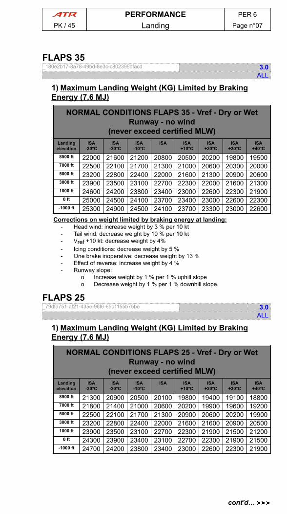
FLAPS 35_180e2b17-8a78-49bd-8e3c-c802399dfacd 3.0
ALL
1) Maximum Landing Weight (KG) Limited by BrakingEnergy (7.6 MJ)
NORMAL CONDITIONS FLAPS 35 - Vref - Dry or WetRunway - no wind
(never exceed certified MLW)Landingelevation
ISA-30°C
ISA-20°C
ISA-10°C
ISA ISA+10°C
ISA+20°C
ISA+30°C
ISA+40°C
8500 ft 22000 21600 21200 20800 20500 20200 19800 195007000 ft 22500 22100 21700 21300 21000 20600 20300 200005000 ft 23200 22800 22400 22000 21600 21300 20900 206003000 ft 23900 23500 23100 22700 22300 22000 21600 213001000 ft 24600 24200 23800 23400 23000 22600 22300 21900
0 ft 25000 24500 24100 23700 23400 23000 22600 22300-1000 ft 25300 24900 24500 24100 23700 23300 23000 22600
Corrections on weight limited by braking energy at landing:- Head wind: increase weight by 3 % per 10 kt- Tail wind: decrease weight by 10 % per 10 kt- Vref +10 kt: decrease weight by 4%- Icing conditions: decrease weight by 5 %- One brake inoperative: decrease weight by 13 %- Effect of reverse: increase weight by 4 %- Runway slope:
o Increase weight by 1 % per 1 % uphill slopeo Decrease weight by 1 % per 1 % downhill slope.
FLAPS 25_79dfa751-af21-435e-96f6-65c1155b75be 3.0
ALL
1) Maximum Landing Weight (KG) Limited by BrakingEnergy (7.6 MJ)
NORMAL CONDITIONS FLAPS 25 - Vref - Dry or WetRunway - no wind
(never exceed certified MLW)Landingelevation
ISA-30°C
ISA-20°C
ISA-10°C
ISA ISA+10°C
ISA+20°C
ISA+30°C
ISA+40°C
8500 ft 21300 20900 20500 20100 19800 19400 19100 188007000 ft 21800 21400 21000 20600 20200 19900 19600 192005000 ft 22500 22100 21700 21300 20900 20600 20200 199003000 ft 23200 22800 22400 22000 21600 21600 20900 205001000 ft 23900 23500 23100 22700 22300 21900 21500 21200
0 ft 24300 23900 23400 23100 22700 22300 21900 21500-1000 ft 24700 24200 23800 23400 23000 22600 22300 21900
PERFORMANCE PER 6
PK / 45 Landing Page n°07
cont'd…
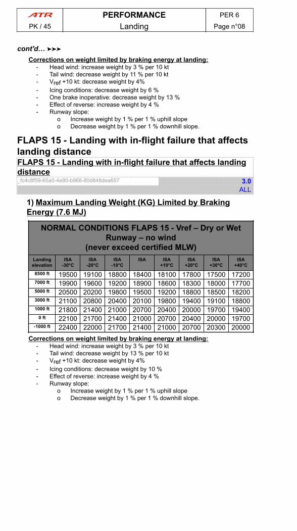
Corrections on weight limited by braking energy at landing:- Head wind: increase weight by 3 % per 10 kt- Tail wind: decrease weight by 11 % per 10 kt- Vref +10 kt: decrease weight by 4%- Icing conditions: decrease weight by 6 %- One brake inoperative: decrease weight by 13 %- Effect of reverse: increase weight by 4 %- Runway slope:
o Increase weight by 1 % per 1 % uphill slopeo Decrease weight by 1 % per 1 % downhill slope.
FLAPS 15 - Landing with in-flight failure that affectslanding distanceFLAPS 15 - Landing with in-flight failure that affects landingdistance_fc4c8f59-65a0-4e90-b968-80d848dea657 3.0
ALL
1) Maximum Landing Weight (KG) Limited by BrakingEnergy (7.6 MJ)
NORMAL CONDITIONS FLAPS 15 - Vref – Dry or WetRunway – no wind
(never exceed certified MLW)Landingelevation
ISA-30°C
ISA-20°C
ISA-10°C
ISA ISA+10°C
ISA+20°C
ISA+30°C
ISA+40°C
8500 ft 19500 19100 18800 18400 18100 17800 17500 172007000 ft 19900 19600 19200 18900 18600 18300 18000 177005000 ft 20500 20200 19800 19500 19200 18800 18500 182003000 ft 21100 20800 20400 20100 19800 19400 19100 188001000 ft 21800 21400 21000 20700 20400 20000 19700 19400
0 ft 22100 21700 21400 21000 20700 20400 20000 19700-1000 ft 22400 22000 21700 21400 21000 20700 20300 20000
Corrections on weight limited by braking energy at landing:- Head wind: increase weight by 3 % per 10 kt- Tail wind: decrease weight by 13 % per 10 kt- Vref +10 kt: decrease weight by 4%- Icing conditions: decrease weight by 10 %- Effect of reverse: increase weight by 4 %- Runway slope:
o Increase weight by 1 % per 1 % uphill slopeo Decrease weight by 1 % per 1 % downhill slope.
PERFORMANCE PER 6
PK / 45 Landing Page n°08
cont'd…
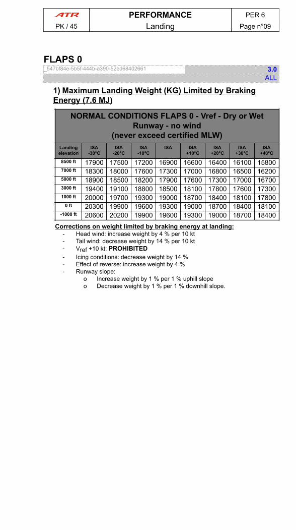
FLAPS 0_547bf84e-5b5f-444b-a390-52ed68402661 3.0
ALL
1) Maximum Landing Weight (KG) Limited by BrakingEnergy (7.6 MJ)
NORMAL CONDITIONS FLAPS 0 - Vref - Dry or WetRunway - no wind
(never exceed certified MLW)Landingelevation
ISA-30°C
ISA-20°C
ISA-10°C
ISA ISA+10°C
ISA+20°C
ISA+30°C
ISA+40°C
8500 ft 17900 17500 17200 16900 16600 16400 16100 158007000 ft 18300 18000 17600 17300 17000 16800 16500 162005000 ft 18900 18500 18200 17900 17600 17300 17000 167003000 ft 19400 19100 18800 18500 18100 17800 17600 173001000 ft 20000 19700 19300 19000 18700 18400 18100 17800
0 ft 20300 19900 19600 19300 19000 18700 18400 18100-1000 ft 20600 20200 19900 19600 19300 19000 18700 18400
Corrections on weight limited by braking energy at landing:- Head wind: increase weight by 4 % per 10 kt- Tail wind: decrease weight by 14 % per 10 kt- Vref +10 kt: PROHIBITED- Icing conditions: decrease weight by 14 %- Effect of reverse: increase weight by 4 %- Runway slope:
o Increase weight by 1 % per 1 % uphill slopeo Decrease weight by 1 % per 1 % downhill slope.
PERFORMANCE PER 6
PK / 45 Landing Page n°09
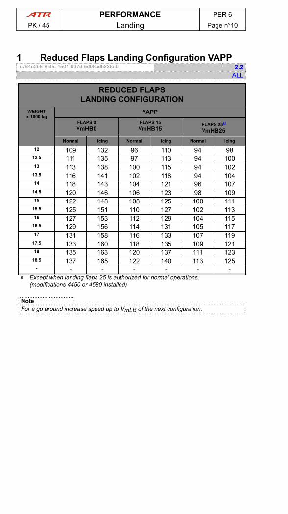
1 Reduced Flaps Landing Configuration VAPP_c764e2b6-850c-4501-9d7d-5d96cdb336e9 2.2
ALL
REDUCED FLAPSLANDING CONFIGURATION
WEIGHTx 1000 kg
VAPPFLAPS 0VmHB0
FLAPS 15VmHB15
FLAPS 25aVmHB25
Normal Icing Normal Icing Normal Icing
12 109 132 96 110 94 9812.5 111 135 97 113 94 10013 113 138 100 115 94 102
13.5 116 141 102 118 94 10414 118 143 104 121 96 107
14.5 120 146 106 123 98 10915 122 148 108 125 100 111
15.5 125 151 110 127 102 11316 127 153 112 129 104 115
16.5 129 156 114 131 105 11717 131 158 116 133 107 119
17.5 133 160 118 135 109 12118 135 163 120 137 111 123
18.5 137 165 122 140 113 125- - - - - - -
a Except when landing flaps 25 is authorized for normal operations.(modifications 4450 or 4580 installed)
NoteFor a go around increase speed up to VmLB of the next configuration.
PERFORMANCE PER 6
PK / 45 Landing Page n°10
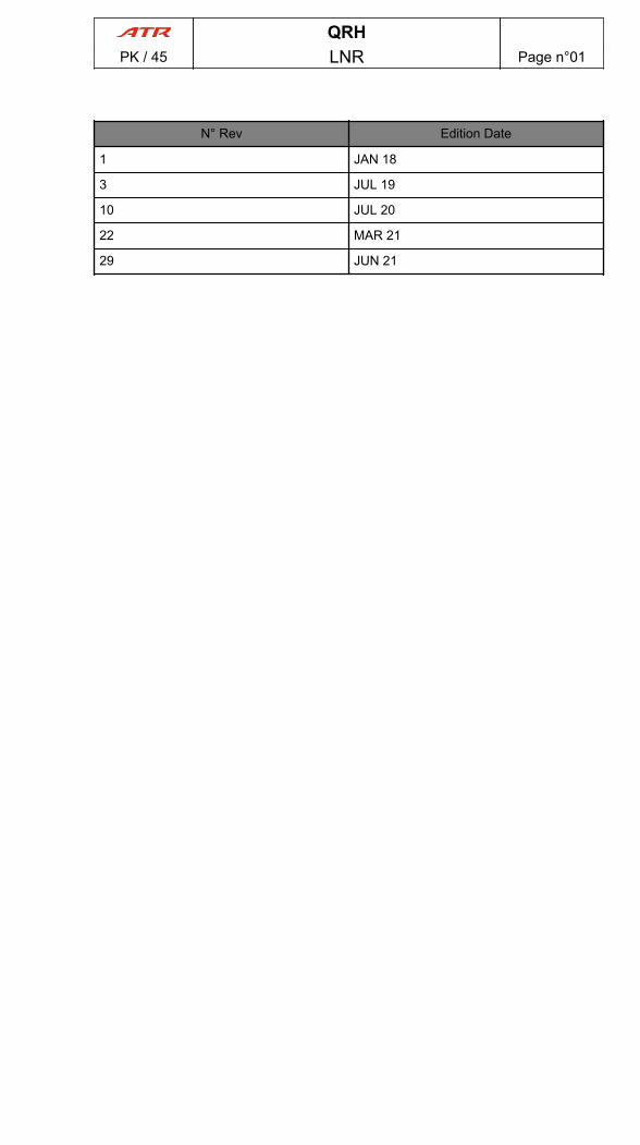
N° Rev Edition Date
1 JAN 18
3 JUL 19
10 JUL 20
22 MAR 21
29 JUN 21
QRHPK / 45 LNR Page n°01

PAGE
INTENTIONALLY
LEFT BLANK
QRHPK / 45 LNR Page n°02
N° Rev RevisionDate
Reason For Issue Impacted DM
1.1 MAY 18- Wording corrections QRH.GEN.1 Introduction- Create DM QRH.PRO.NNO.EMR.70.05.E70.05
ENG 1+2 FLAME OUT- Configuration management QRH.PRO.NNO.ABN.70.2.6.A70.12
SINGLE ENG OPERATION- Configuration management QRH.PRO.NOP.NOR.6.8 Pedestal
and Central Panels- Editorial improvement QRH.NCL.1.1 REFER TO- Check list updated QRH.NCL.1.2 FINAL COCKPIT
PREPARATION- Check List updated QRH.NCL.1.3 BEFORE
PROPELLER ROTATION- Create DM QRH.NCL.1.4 BEFORE TAXI- Check list updated QRH.NCL.1.5 TAXI- Create DM QRH.NCL.1.6 BEFORE TAKE OFF- Create DM QRH.NCL.1.7 AFTER TAKEOFF- Check list updated QRH.NCL.1.8 DESCENT- Check list updated QRH.NCL.1.9 APPROACH- Check list updated QRH.NCL.1.10 BEFORE LANDING- Create DM QRH.NCL.1.11 AFTER LANDING- Check list updated QRH.NCL.1.12 PARKING- Check list Updated QRH.NCL.1.13 LEAVING
AIRCRAFT- Illustration's size updated QRH.NCL.1.14 TAKEOFF TRIM
3.0 JUL 19- Editorial approvement QRH.OEB.00 GENERAL
DESCRIPTIONALL
- Configuration management update QRH.OEB.25 Propeller Blade PitchChange Mechanism Damage (R)ALL
- Link updated : AFM - Procedure forIcing Conditions
QRH.OEB.25 Propeller Blade PitchChange Mechanism DamageALL
- No Technical Change - EditorialImprovement
QRH.OEB.27 UncommandedAutofeather (R)ALL
- Update OEB numbering QRH.OEB.27 UncommandedAutofeatherALL
- No Technical Change - EditorialImprovement
QRH.OEB.28 MFC 1B and-or MFC2B Fault (R)ALL
- No content change, configurationmanagement update.
QRH.OEB.28 MFC 1B and-or MFC2B FaultALL
- No Technical Change - Editorialimprovement
QRH.OEB.30 Spurious Glide SlopeCapture (R)ALL
- Update OEB numbering QRH.OEB.30 Spurious Glide SlopeCaptureALL
- No content change, configurationmanagement updated
QRH.OEB.32 ENGINE FIREWarning (R)ALL
- No content change, configurationmanagement updated
QRH.OEB.32 ENGINE FIREWarningALL
- No content change, structureimprovement.
QRH.OEB.36 Bank angle limitationin Severe Icing Conditions (R)ALL
- Update OEB numbering QRH.OEB.36 Bank angle limitationin Severe Icing ConditionsALL
QRHPK / 45 RNR Page n°01
N° Rev RevisionDate
Reason For Issue Impacted DM
- No Technical Change - EditorialImprovement
QRH.OEB.42 Static Inverter DoubleLoss (R)ALL
- Update OEB numbering QRH.OEB.42 Static Inverter DoubleLossALL
- No technical change, Editorialimprovement
QRH.OEB.43 Cockpit VoiceRecorder (R)0665
- Update OEB numbering QRH.OEB.43 Cockpit VoiceRecorder0665
- Wording corrections QRH.GEN.1 IntroductionALL
- Create DM QRH.GEN.3 Failure ConsequencesAnalysisALL
- Complete revision of the limitationintroduction
QRH.LIM.1.1 IntroductionALL
- Create DM to separate Kg/Lb unitsfor Center of GravityEnvelope.Wording modification:Warning added.
QRH.LIM.3.2.1.1 Certified Center ofGravity EnvelopeALL
- Create DM QRH.LIM.4.1 AIRSPEEDLIMITATIONSALL
- Introduction of a footnote (a) Applyworst condition in order to clarifywhich limitations isapplicable.Hyperlink correction.
QRH.LIM.5.2.1.2 CrosswindALL
- Create DM QRH.LIM.5.3.1.2 Operations OnNarrow RunwaysALL
- Create DM QRH.LIM.5.5.1.1 Cat 2 Approach -AP-FD UseALL
- Create DM QRH.LIM.5.5.1.2 Cat 2 Approach -AP-FD HeightsALL
- No content change, configurationmanagement update.
QRH.LIM.6.3.1.1 Electrical SystemALL
- No content change - ConfigurationManagement update
QRH.LIM.6.4.1.1 FlapsALL
- RNP 2 capabilities updated QRH.LIM.6.6.1.1 PBN CapabilitiesALL
- Change value of Overtorque Limit QRH.LIM.6.9.1.4 Overtorque LimitALL
- Change the value of Over TQ Limit QRH.LIM.6.9.1.6 EngineParametersALL
- Create DM QRH.LIM.6.10.1.1 Fuel SystemALL
- Introduction of a footnote (a) Applyworst condition in order to clarifywhich limitations is applicable.
QRH.LIM.7.2.1.1 LimitationsALL
- Modification of the commentassociated with the "CABIN CREW(PA)......ADVISE FOR ACTION"action in order to be in line with theCCOM procedure.
QRH.PRO.NNO.EMR.26.3.E26.02AFT SMOKEALL
- Correction of a typo“CARREFULLY” is replaced by“CAREFULLY”.
QRH.PRO.NNO.EMR.26.4.E26.03AIR COND SMOKEALL
QRHPK / 45 RNR Page n°02

N° Rev RevisionDate
Reason For Issue Impacted DM
- Modification of the commentassociated with the "CABIN CREW(PA)......ADVISE FOR ACTION"action in order to be in line with theCCOM procedure.
QRH.PRO.NNO.EMR.26.7.E26.06FWD SMOKEALL
- ENG RELIGHT………MONITORprocedure line is replaced by ENGRELIGHT : MONITOR.
QRH.PRO.NNO.EMR.70.05.E70.05ENG 1+2 FLAME OUTALL
- Addition of "ATC ...... NOTIFY" atthe beginning of the "BOMB ONBOARD" procedure.
QRH.PRO.NNO.EMR.99.1.E99.01BOMB ON BOARDALL
- Introduction of two procedure lineslinked to ELT:- EMER LOCXMTR…..MAN, and- EMER LOCXMTR…..CHECK EMITTING.
QRH.PRO.NNO.EMR.99.2.E99.03DITCHINGALL
- Correction of the followingcomment in layer 2:-During anemergency evacuation on ground,PA should be used to communicatewith cabin crew.- replaces :-Only PAavailable on battery to ensure cabincommunication.-
QRH.PRO.NNO.EMR.99.4.E99.05EMERGENCY EVACUATION (ONGROUND)ALL
- Introduction of two procedure lineslinked to ELT:- EMER LOCXMTR…..MAN, and- EMER LOCXMTR…..CHECK EMITTING.
QRH.PRO.NNO.EMR.99.5.E99.06FORCED LANDINGALL
- Procedure review QRH.PRO.NNO.EMR.99.7.E99.08SEVERE ICINGALL
- Update of the link (s) to remove"AFM" or "FCOM" indications.
QRH.PRO.NNO.ABN.21.3.2.A21.10EXCESS CAB ALTALL
- Create DM: XPDR swapping innormal and abnormal procedure
QRH.PRO.NNO.ABN.23.5.A23.05XPDR FAULTALL
- Aircraft configuration managementin order to cover all aircraftconfigurations.
QRH.PRO.NNO.ABN.24.1.2.2 LostEquipment ListALL
- Create DM: AC STBY BUSImprovement.
QRH.PRO.NNO.ABN.24.1.3.A24.0326 V AC STBY BUS FAULTDETECTIONALL
- Create DM QRH.PRO.NNO.ABN.24.1.4.A24.0426 V AC STBY BUS FAULTALL
- Create DM QRH.PRO.NNO.ABN.24.1.4.2 26 VAC STBY BUS FAULT- Lostequipment listALL
- Create DM 42-400, 42-500,72-101, 72-102, 72-201, 72-202,72-211, 72-212, 72-212A
QRH.PRO.NNO.ABN.24.1.5.A24.05115 V AC STBY BUS FAULTALL
- Create DM 42-400, 42-500,72-101, 72-102, 72-201, 72-202,72-211, 72-212, 72-212A
QRH.PRO.NNO.ABN.24.1.5.2 115 VAC STBY BUS FAULT- Lostequipment listALL
- Removal of the comment in layer 2for simplification purpose.
QRH.PRO.NNO.ABN.24.2.1.A24.06ACW BUS 1 OFFALL
- Update and wordingstandardization of items listed in theassociated lost equipment list.
QRH.PRO.NNO.ABN.24.2.1.2 LostEquipment ListALL
- Link updated QRH.PRO.NNO.ABN.24.2.2.A24.07ACW BUS 2 OFFALL
- Introduction of TRU not available isthe associated lost equipement listfor applicable aircraft models.
QRH.PRO.NNO.ABN.24.2.2.2 LostEquipment ListALL
QRHPK / 45 RNR Page n°03
N° Rev RevisionDate
Reason For Issue Impacted DM
- Correction of typos in associatedprocedure lines -ACW GEN 1+2FAULT is replaced by ACW GEN1+2 LOSS.HYD GREEN AND BLUEMAIN PUMPS…OFF is duplicated intwo procedure lines in order to avoidflight crew misunderstanding.
QRH.PRO.NNO.ABN.24.2.4.A24.09ACW GEN 1+2 LOSSALL
- Introduction of "CAPT PITOT HTG"and "CAPT TAT ALPHA HTG" in theassociated lost equipement list.
QRH.PRO.NNO.ABN.24.2.4.2 LostEquipment ListALL
- No content change, configurationmanagement updated
QRH.PRO.NNO.ABN.24.3.1.A24.10BAT Discharge in FlightALL
- Duplication of the -Lost EquipmentList- in 2 parts for clarification purpose.
QRH.PRO.NNO.ABN.24.3.5.2 LostEquipment List - Part 1ALL
- Duplication of the -Lost EquipmentList- in 2 parts for clarification purpose.
QRH.PRO.NNO.ABN.24.3.5.3 LostEquipment List - Part 2ALL
- Introduction of the new DM in orderto indicate the TRU.
QRH.PRO.NNO.ABN.24.4.1.1 AirALL
- Introduction of the new DM in orderto indicate the TRU.
QRH.PRO.NNO.ABN.24.4.1.2AutopilotALL
- Introduction of the new DM in orderto indicate the TRU.
QRH.PRO.NNO.ABN.24.4.1.3CommunicationALL
- Introduction of the new DM in orderto indicate the TRU.
QRH.PRO.NNO.ABN.24.4.1.4 FlightControlsALL
- Introduction of the new DM in orderto indicate the TRU.
QRH.PRO.NNO.ABN.24.4.1.5HydraulicALL
- Introduction of the new DM in orderto indicate the TRU.
QRH.PRO.NNO.ABN.24.4.1.6Indicating and Recording SystemsALL
- Introduction of the new DM in orderto indicate the TRU.
QRH.PRO.NNO.ABN.24.4.1.7Landing GearALL
- Introduction of the new DM in orderto indicate the TRU.
QRH.PRO.NNO.ABN.24.4.1.8LightsALL
- Introduction of the new DM in orderto indicate the TRU.
QRH.PRO.NNO.ABN.24.4.1.9NavigationALL
- Introduction of the new DM in orderto indicate the TRU.
QRH.PRO.NNO.ABN.24.4.1.10Power PlantALL
- Introduction of the new DM in orderto indicate the TRU.
QRH.PRO.NNO.ABN.24.4.1.11MiscellaneousALL
- Update of the Note in order to addlinks to QRH.
QRH.PRO.NNO.ABN.27.1.5.A27.05REDUCED FLAPS LANDINGALL
- Introduction of a comment in layer2 when pitch disconnect occured onground.
QRH.PRO.NNO.ABN.27.2.2.A27.07PITCH DISCONNECTALL
- Creation of a new FUEL LEAKalert condition in order to have thecontent in all ops manuals (AFM/FCOM/QRH).
QRH.PRO.NNO.ABN.28.2.A28.04FUEL LEAK DETECTIONALL
- No content change, configurationmanagement updated
QRH.PRO.NNO.ABN.28.5.A28.05FUEL LEAKALL
QRHPK / 45 RNR Page n°04
N° Rev RevisionDate
Reason For Issue Impacted DM
- Introduction of a new procedureline TAXI: ON ENG 1+2 in order tokeep remaining hydraulic pumpoperative powered by ACW powerduring taxi.
QRH.PRO.NNO.ABN.29.2.A29.02HYD BLUE (GREEN) LO PRALL
- Introduction of a new procedureline: TAXI ON ENG 1+2 in order tokeep remaining hydraulic pumpoperative powered by ACW powerduring taxi.
QRH.PRO.NNO.ABN.29.3.A29.03HYD BLUE (GREEN) OVHTALL
- Creation of this content in order toplit the DE/ANTI ICING procedure
QRH.PRO.NNO.ABN.30.2.5.A30.09DE ICING ENG 1(2) FAULTALL
- Creation of a new DM, based onexisting 45-72, with MOD CAT 2(1112) in which “ILS CAT 2 :PROHIBITED” limitation is added inthe PROBE HTG PITOT/STAT/TATcondition.
QRH.PRO.NNO.ABN.30.4.1.A30.11PROBES HTG FAILUREALL
- Procedure review QRH.PRO.NNO.ABN.30.5.2.A30.15DEGRADED PERFALL
- Create DM: Procedure review QRH.PRO.NNO.ABN.30.5.1.A30.17SEVERE ICING DETECTIONALL
- DM updated: procedure review QRH.PRO.NNO.ABN.30.5.3.A30.16INCREASE SPEEDALL
- Update of the content in order toclarify that the autofeather lost is onthe Engine 2.
QRH.PRO.NNO.ABN.31.2.6.A31.10MFC 2A+2B FAULTALL
- No content change - Configuration management update
QRH.PRO.NNO.ABN.36.1.A36.02BLEED 1(2) LEAKALL
- Correction of typos:PEC FAULT isreplaced by PEC 1(2) FAULTPECSGL CH : DO NOT RESET isreplaced by PEC 1(2) : DO NOTRESETRemoval of the sentenceMAINTENANCE ACTIONREQUIRED because no action ofmaintenance is required after thefailure of aPEC single channel.
QRH.PRO.NNO.ABN.70.1.5.A70.06PEC 1(2) SGL CHALL
- OIL TEMP AND PRESS……….MONITOR procedure line isreplaced by OIL TEMP ANDPRESS: MONITOR.
QRH.PRO.NNO.ABN.70.2.2.A70.09ENG RESTART IN FLIGHTALL
- In the last condition, "beforenosewheel is on the ground" isreplaced by "until nosewheeltouches the ground".
QRH.PRO.NNO.ABN.70.2.6.A70.12SINGLE ENG OPERATIONALL
- Create DM for aircraft configurationupdate.
QRH.PRO.NNO.ABN.70.3.1.A70.13ABNORMAL ENG PARAMETERSIN FLIGHTALL
- Change "eng" to "ENG" , in orderto improve the wording.introduceaffected ENG, to clarify the content
QRH.PRO.NNO.ABN.70.3.5.A70.17ENG 1(2) OVER LIMITALL
- Put in capital letters the alertExcessive ITT during start
QRH.PRO.NNO.ABN.70.5.1.A70.22ABNORMAL PARAMETERSDURING STARTALL
- Addition of 2 conditions QRH.PRO.NNO.ABN.99.1.4.A99.04SMK DET FANS FAULTALL
QRHPK / 45 RNR Page n°05
N° Rev RevisionDate
Reason For Issue Impacted DM
- Comment in layer 2 in the FCOM ismodified in order to improve thewording for standardizationpurposes (LH maintenance panel)
QRH.PRO.NOP.NOR.4.2 GPUAvailableALL
- Revision of the Right Aft Fuselageparagraph in external inspectionchapter in order to add Emer Lightinspection
QRH.PRO.NOP.NOR.5 ExternalInspectionALL
- DM updated: XPDR sw added QRH.PRO.NOP.NOR.6.3 Pedestaland Central PanelsALL
- No content change, configurationmanagement update
QRH.PRO.NOP.NOR.6.4 LateralPanelsALL
- Update of the link associated withthe Trims test.
QRH.PRO.NOP.NOR.6.5 ShortTransitALL
- No technical change, aircraftconfiguration update
QRH.PRO.NOP.NOR.9 FinalCockpit Preparation (Step 3)ALL
- No content change, configurationmanagement updated
QRH.PRO.NOP.NOR.12 Before TaxiALL
- Update of the content in order tospecify that Taxi should be alsodone below GI
QRH.PRO.NOP.NOR.13 TaxiALL
- No technical change, aircraftconfiguration update
QRH.PRO.NOP.NOR.15 TakeoffALL
- No technical change, aircraftconfiguration update.
QRH.PRO.NOP.NOR.23 Go-AroundALL
- Update of the ATPCS refer tolink.Correction of the conditionbefore CL feather order -After 2 minbelow Flight Idle (FI)- replaces -After1 min in Ground Idle-.
QRH.PRO.NOP.NOR.24 AfterLandingALL
- Update of the procedure Parking inorder to clarify that the case ofmarshaller at apron switch off TAXIT.O. light is recommended to notblind him.
QRH.PRO.NOP.NOR.25 ParkingALL
- Modification of the note in order toupdate the refer to.
QRH.PRO.NOP.NOR.26 LeavingThe AircraftALL
- Procedure review QRH.PRO.NOP.ICE.2 Procedure forIcing ConditionsALL
- Create DM: Procedure review QRH.PRO.NOP.ICE.A30.17SEVERE ICING DETECTIONALL
- Update of the title in order tospecify that the Static test is linkedto the ATPCS system.
QRH.PRO.SYSTEM TEST.29.3ATPCS Static TestALL
- Actual comment in layer 2 listed inthe FCOM is modified in layer 1 inorderto be displayed in AFM/FCOM/QRH manuals.
QRH.PRO.SYSTEM TEST.28.3TrimsALL
- Procedure review QRH.ICE.1.2 Procedure for IcingConditionsALL
- Create DM: Procedure review QRH.ICE.2.A30.17 SEVERE ICINGDETECTIONALL
- Procedure review QRH.ICE.4.A30.15 DEGRADEDPERFALL
- DM updated: procedure review QRH.ICE.5.A30.16 INCREASESPEEDALL
QRHPK / 45 RNR Page n°06

N° Rev RevisionDate
Reason For Issue Impacted DM
- Procedure review QRH.ICE.6.E99.08 SEVERE ICINGALL
- Additional information on 2engines cruise parameters tables
QRH.PER.1.1 IntroductionALL
- Highlighting of the Icing FlightLevels in the QRH OPSDATA tablesas a bold line if any.
QRH.PER.3.6 13 TALL
- Highlighting of the Icing FlightLevels in the QRH OPSDATA tablesas a bold line if any.
QRH.PER.3.7 14 TALL
- Highlighting of the Icing FlightLevels in the QRH OPSDATA tablesas a bold line if any.
QRH.PER.3.8 15 TALL
- Highlighting of the Icing FlightLevels in the QRH OPSDATA tablesas a bold line if any.
QRH.PER.3.9 16 TALL
- Highlighting of the Icing FlightLevels in the QRH OPSDATA tablesas a bold line if any.
QRH.PER.3.10 17 TALL
- Highlighting of the Icing FlightLevels in the QRH OPSDATA tablesas a bold line if any.
QRH.PER.3.11 18 TALL
- Highlighting of the Icing FlightLevels in the QRH OPSDATA tablesas a bold line if any.
QRH.PER.3.12 18.6 TALL
- Wording modifications forstandardization purpose
QRH.PER.6.1.2.1 Actual LandingDistance - Sea LevelALL
- Create DM QRH.PER.6.1.1 Runway StatusALL
- Modification of the DM title forclarification purpose and updated'Braking Definitions' and'Methodology' paragraphs.
QRH.PER.6.2.2.1 MaximumLanding Weight Limited by BrakingEnergyALL
- Removal of 'a)Normal Braking' QRH.PER.6.2.2.2 FLAPS 35ALL
- Removal of 'a)Normal Braking' QRH.PER.6.2.2.3 FLAPS 25ALL
- Removal of 'a)Normal Braking' QRH.PER.6.2.2.4 FLAPS 15 -Landing with in-flight failure thataffects landing distanceALL
- Removal of 'a)Normal Braking' QRH.PER.6.2.2.5 FLAPS 0ALL
- Addition of "VAPP" in DM title. QRH.PER.6.3.1 Reduced FlapsLanding Configuration VAPPALL
- Editorial improvement QRH.NCL.1.1 REFER TOALL
- Check list updated QRH.NCL.1.2 FINAL COCKPITPREPARATIONALL
- Check list updated and removal ofthe second title that is useless.
QRH.NCL.1.3 BEFOREPROPELLER ROTATIONALL
- Create DM QRH.NCL.1.4 BEFORE TAXIALL
- Check list updated QRH.NCL.1.5 TAXIALL
- Create DM QRH.NCL.1.6 BEFORE TAKEOFFALL
- Create DM QRH.NCL.1.7 AFTER TAKEOFFALL
- Check list updated QRH.NCL.1.8 DESCENTALL
- Check list updated QRH.NCL.1.9 APPROACHALL
QRHPK / 45 RNR Page n°07
N° Rev RevisionDate
Reason For Issue Impacted DM
- Check list updated QRH.NCL.1.10 BEFORE LANDINGALL
- Correction of the condition beforeCL feather order -After 2 min belowFlight Idle (FI)- replaces -After 1 minin Ground Idle-.
QRH.NCL.1.11 AFTER LANDINGALL
- Check list updated QRH.NCL.1.12 PARKINGALL
- Check list Updated QRH.NCL.1.13 LEAVING THEAIRCRAFTALL
- Correction of the followingcomment in layer 2:-During anemergency evacuation on ground,PA should be used to communicatewith cabin crew.- replaces :-Only PAavailable on battery to ensure cabincommunication.-
QRH.NCL.1.E99.05 EMERGENCYEVACUATION (ON GROUND)ALL
- Illustration's size updated QRH.NCL.1.14 TAKEOFF TRIMALL
10.0 JUL 20- Configuration management update(FCOM impact only).
QRH.OEB.25 Propeller Blade PitchChange Mechanism Damage (R)ALL
- Uniformization of - FUEL S.O. -wording
QRH.OEB.25 Propeller Blade PitchChange Mechanism DamageALL
- Uniformization of - FUEL S.O. -wording
QRH.OEB.27 UncommandedAutofeatherALL
- No content change, configurationmanagement updated
QRH.OEB.32 ENGINE FIREWarning (R)ALL
- No content change, configurationmanagement updated
QRH.OEB.32 ENGINE FIREWarningALL
- No content change, structureimprovement.
QRH.OEB.36 Bank angle limitationin Severe Icing Conditions (R)ALL
- Configuration management andaddition of the modification 06170and 07075 in the –Cancel by-section.
QRH.OEB.43 Cockpit VoiceRecorder (R)0665
- Configuration management andaddition of the modification 06170and 07075 in the –Cancel by-section.
QRH.OEB.43 Cockpit VoiceRecorder0665
- Create new OEB N°49 QRH.OEB.49 Temporary ENG 1(2)OIL LO PR procedure (R)ALL
- Create new OEB N°49 QRH.OEB.49 Temporary ENG 1(2)OIL LO PR procedureALL
- Complete revision of the limitationintroduction
QRH.LIM.1.L00.00 IntroductionALL
- Correction of VFE (flaps 15) inaccordance with aircraftconfiguration and hyperlink updatedto specify VMCG limitation.
QRH.LIM.4.1 AIRSPEEDLIMITATIONSALL
- Create DM QRH.LIM.5.3.1.2 Operations OnNarrow RunwaysALL
- No content change, Structureimprovement and title change.
QRH.LIM.5.5.1.1.1 AP-FD UseALL
- No content change, Structureimprovement and title change.
QRH.LIM.5.5.1.1.2 AP-FD HeightsALL
QRHPK / 45 RNR Page n°08
N° Rev RevisionDate
Reason For Issue Impacted DM
- No content change. Configurationmanagement update.
QRH.LIM.5.5.1.1.3 MaximumDemonstrated CrosswindALL
- No technical change , aircraftconfiguration update.
QRH.LIM.5.5.1.1.4 MinimumEquipment RequiredALL
- Create DM QRH.LIM.5.5.1.1 Cat 2 Approach -AP-FD UseALL
- Create DM QRH.LIM.5.5.1.2 Cat 2 Approach -AP-FD HeightsALL
- Creation of DM in order tointroduce Mod 04083
QRH.LIM.6.7.1.1 Minimum BottlePressureALL
- Change of the torque value from121.8% to 122%.
QRH.LIM.6.9.1.4 Overtorque LimitALL
- Addition of a footnote linked toTransient case.
QRH.LIM.6.9.1.6 EngineParametersALL
- Create DM QRH.LIM.6.10.1.1 Fuel SystemALL
- addition of a hyperlink reference toBUS Equipment List section.
QRH.PRO.NNO.EMR.24.01.E24.01DC GEN 1+2 FAULTALL
- No content change, configurationmanagement updated
QRH.PRO.NNO.EMR.26.3.E26.02AFT SMOKEALL
- For NAMS system options and preNAMS: ENG BLEED replacesBLEED VALVE
QRH.PRO.NNO.EMR.26.7.E26.06FWD SMOKEALL
- Create new PITCH CONTROLJAM at TAKEOFF or LANDINGprocedure
QRH.PRO.NNO.EMR.27.1.E27.01PITCH CONTROL JAM ATTAKEOFF OR LANDINGALL
- FIRE HANDLE (affected ENG)replaces FIRE HANDLE (red lighton).
QRH.PRO.NNO.EMR.70.01.E70.01ENG 1(2) FIRE AT TAKEOFFALL
- ENG RELIGHT………MONITORprocedure line is replaced by ENGRELIGHT : MONITOR.
QRH.PRO.NNO.EMR.70.05.E70.05ENG 1+2 FLAME OUTALL
- No content change, configurationmanagement updated
QRH.PRO.NNO.EMR.99.1.E99.01BOMB ON BOARDALL
- Addition of a comment linked to -AUTO PRESS DUMP...ON- actionline (FCOM impact only)
QRH.PRO.NNO.EMR.99.3.E99.03DITCHINGALL
- Addition of a comment linked to -AUTO PRESS DUMP...ON- actionline (FCOM impact only)
QRH.PRO.NNO.EMR.99.5.E99.05EMERGENCY EVACUATION (ONGROUND)ALL
- Addition of a comment linked to -AUTO PRESS DUMP...ON- actionline (FCOM impact only)
QRH.PRO.NNO.EMR.99.6.E99.06FORCED LANDINGALL
- Procedure review QRH.PRO.NNO.EMR.99.8.E99.08SEVERE ICINGALL
- Introduction of the FCOMprocedure in AFM
QRH.PRO.NNO.ABN.21.1.3.A21.03PACK 1+2 VALVES FAULTALL
- Update of the table: 6700 replaces6800 in FL 250 column.
QRH.PRO.NNO.ABN.21.3.1.A21.10AUTO PRESS FAULTALL
- PACK 1+2 replace by PACKVALVE 1+2
QRH.PRO.NNO.ABN.21.3.3.A21.14EXCESS CAB DELTA PALL
QRHPK / 45 RNR Page n°09

N° Rev RevisionDate
Reason For Issue Impacted DM
- No content change, configurationmanagement update.
QRH.PRO.NNO.ABN.23.5.A23.05XPDR FAULTALL
- Aircraft configuration managementin order to cover all aircraftconfigurations.
QRH.PRO.NNO.ABN.24.1.2.2 LostEquipment ListALL
- No technical change, aircraftconfiguration update.
QRH.PRO.NNO.ABN.24.1.5.2 115 VAC STBY BUS FAULT- Lostequipment listALL
- Removal of the comment in layer 2for simplification purpose.
QRH.PRO.NNO.ABN.24.2.1.A24.06ACW BUS 1 OFFALL
- Link updated QRH.PRO.NNO.ABN.24.2.2.A24.07ACW BUS 2 OFFALL
- Modification of a comment (ImpactFCOM only). Deletion of the CAPTstick information.
QRH.PRO.NNO.ABN.24.3.1.A24.11DC BUS 1 OFFALL
- Addition of - DC SVCE-UTLY BUSpb : MAINTAIN ON - action line, andan associated comment (ImpactFCOM only).
QRH.PRO.NNO.ABN.24.3.2.A24.12DC BUS 2 OFFALL
- Duplication of the -Lost EquipmentList- in 2 parts for clarification purpose.
QRH.PRO.NNO.ABN.24.3.5.2 LostEquipment List - Part 1ALL
- Duplication of the -Lost EquipmentList- in 2 parts for clarification purpose.
QRH.PRO.NNO.ABN.24.3.5.3 LostEquipment List - Part 2ALL
- Create new DM : PITCHCONTROL JAM IN FLIGHT
QRH.PRO.NNO.ABN.27.2.1.A27.06PITCH CONTROL JAM IN FLIGHTALL
- Pitch Disconnect Procedure ismodified to take into account themodifications of Elevator JamProcedure
QRH.PRO.NNO.ABN.27.2.2.A27.07PITCH DISCONNECTALL
- Update of information linked withMMEL manual.
QRH.PRO.NNO.ABN.27.3.1.A27.14AIL LOCK LITALL
- No content change, configurationmanagement updated
QRH.PRO.NNO.ABN.28.5.A28.05FUEL LEAKALL
- Aircraft configuration managementupdate. Addition of a layer in orderto inform that the feeder jet pump ofthe affected tank is unavailable(FCOM). Replace EACH TANK byAFFECTED TANK.
QRH.PRO.NNO.ABN.28.4.A28.06FUEL LO LVLALL
- No content change, configurationmanagement update.
QRH.PRO.NNO.ABN.30.5.2.A30.15DEGRADED PERFALL
- No content change, strutureimprovement.
QRH.PRO.NNO.ABN.30.5.3.A30.16SEVERE ICING DETECTIONALL
- DM updated: procedure review QRH.PRO.NNO.ABN.30.5.4.A30.17INCREASE SPEEDALL
- No content change, configurationmanagement updated
QRH.PRO.NNO.ABN.31.2.1.A31.05MFC 1A+1B FAULTALL
- Modification content QRH.PRO.NNO.ABN.32.6.A32.06LANDING WITH ABNORMAL LDGGEARALL
QRHPK / 45 RNR Page n°10

N° Rev RevisionDate
Reason For Issue Impacted DM
- Update of the AHRS1 comment, inorder to describe the effect ofAHRS1 malfunction on thestabilization signal (Impact FCOMonly)
QRH.PRO.NNO.ABN.34.2.1.A34.05AHRS 1(2) FAILUREALL
- Replace PFD with EADI/EHSI. QRH.PRO.NNO.ABN.34.2.6.A34.10EFIS COMPALL
- Action BOTH PACKS SUPPLYFROM ONE SINGLE BLEED :PROHIBITED removed
QRH.PRO.NNO.ABN.36.1.A36.01AIR BLEED X VALVE OPENALL
- Modification content : Deleted BLEED VALVE - Added ENGBLEED
QRH.PRO.NNO.ABN.36.1.A36.02BLEED LEAK 1(2)ALL
- Content Modification ENG BLEEDinstead of BLEED VALVE
QRH.PRO.NNO.ABN.36.2.A36.03BLEED 1(2) OVHTALL
- Modification Title and content :Deleted BLEED VALVE - Added :ENG BLEED
QRH.PRO.NNO.ABN.36.3.A36.04ENG BLEED 1(2) FAULTALL
- Create DM configuration 05567and (03713 or 03761), APM andPEC.
QRH.PRO.NNO.ABN.70.2.2.A70.09ENG RESTART IN FLIGHTALL
- Comment in layer 2 in the FCOM ismodified in order to improve thewording for standardizationpurposes (LH maintenance panel)
QRH.PRO.NOP.NOR.4.2 GPUAvailableALL
- To be in accordance with the labelof the panel/handle, ENG 1(2) FIREreplaces ENG FIRE 1(2)
QRH.PRO.NOP.NOR.6.1 CockpitPreparation (Step 2)ALL
- To be in accordance with the labelof the panel/handle, ENG 1(2) FIREreplaces ENG FIRE 1(2)
QRH.PRO.NOP.NOR.6.2 OverheadPanelALL
- To be in accordance with the labelof the panel/handle, ENG 1(2) FIREreplaces ENG FIRE 1(2).Configuration management updated:added MOD 10046, 07970 and08866
QRH.PRO.NOP.NOR.6.5 ShortTransitALL
- -FINAL COCKPIT PREPC/L ........ORDER- and -FINALCOCKPIT PREP C/L .. .PERFORM- actions moved from thePF-PM table to a new CAPT-F/Otable.
QRH.PRO.NOP.NOR.9 FinalCockpit Preparation (Step 3)ALL
- Improvement of the wording inorder to recommend to use exciter A+B for the first flight of the day.
QRH.PRO.NOP.NOR.10 HotelMode Start UpALL
- Update of RTO TQ informations forclarification purpose.
QRH.PRO.NOP.NOR.11 BeforePropeller RotationALL
- Move of the -Reaching 70kt- part inthe PF-PM table below.
QRH.PRO.NOP.NOR.15 TakeoffALL
- Braking action moved at main LGtouch down and explanatory noteadded.
QRH.PRO.NOP.NOR.22 LandingALL
- Modification of the attributes of thetable to replace CAPT-F/O by PF-PM.
QRH.PRO.NOP.NOR.23 Go-AroundALL
- Introduction of a commentassociated with CL2...FUEL S.O.procedure line to provideexplanations (FCOM impact only).
QRH.PRO.NOP.NOR.25 ParkingALL
- Modification of the note in order toupdate the refer to. Addition of NHvalue to FUEL PUMP items.
QRH.PRO.NOP.NOR.26 LeavingThe AircraftALL
QRHPK / 45 RNR Page n°11
N° Rev RevisionDate
Reason For Issue Impacted DM
- Procedure review QRH.PRO.NOP.ICE.2 Procedure forIcing ConditionsALL
- No content change, strutureimprovement.
QRH.PRO.NOP.ICE.A30.16SEVERE ICING DETECTIONALL
- Uniformization of FUEL SO REDlight wording
QRH.PRO.SYSTEM TEST.29.1Engine Fire ProtectionALL
- Addition of two action lines: NP1(2) indication .... DECREASEBELOW 20 percent.
QRH.PRO.SYSTEM TEST.28.1ATPCS Dynamic TestALL
- Addition of FDAU check. QRH.PRO.SYSTEM TEST.28.5APMALL
- Procedure review QRH.ICE.1.2 Procedure for IcingConditionsALL
- No content change, strutureimprovement.
QRH.ICE.2.A30.16 SEVERE ICINGDETECTIONALL
- No content change, configurationmanagement update.
QRH.ICE.4.A30.15 DEGRADEDPERFALL
- DM updated: procedure review QRH.ICE.5.A30.17 INCREASESPEEDALL
- Procedure review QRH.ICE.6.E99.08 SEVERE ICINGALL
- Additional information on 2engines cruise parameters tables
QRH.PER.1.1 IntroductionALL
- Modification of the DM title forclarification purpose and updated'Braking Definitions' and'Methodology' paragraphs.
QRH.PER.6.2.2.1 MaximumLanding Weight Limited by BrakingEnergyALL
- No content change. Configurationmanagement update.
QRH.PER.6.2.2.2 FLAPS 35ALL
- No content change. Configurationmanagement update.
QRH.PER.6.2.2.3 FLAPS 25ALL
- No content change. Configurationmanagement update.
QRH.PER.6.2.2.4 FLAPS 15 -Landing with in-flight failure thataffects landing distanceALL
- No content change. Configurationmanagement update.
QRH.PER.6.2.2.5 FLAPS 0ALL
- In the FINAL COCKPITPREPARATION, -FMS- is replacedby -GNSS-.
QRH.NCL.1.2 FINAL COCKPITPREPARATIONALL
- Correction of the condition beforeCL feather order -After 2 min belowFlight Idle (FI)- replaces -After 1 minin Ground Idle-.
QRH.NCL.1.11 AFTER LANDINGALL
- Addition of a comment linked to -AUTO PRESS DUMP...ON- actionline (FCOM impact only)
QRH.NCL.1.E99.05 EMERGENCYEVACUATION (ON GROUND)ALL
22.0 MAR 21- Removal of -operative- word inorder to avoid misunderstanding.
QRH.OEB.28 MFC 1B and-or MFC2B FaultALL
- Content update to improve unitvalue linked to VmLB0 Icing speed.
QRH.OEB.36 Bank angle limitationin Severe Icing ConditionsALL
- No content change, configurationmanagement updated
QRH.OEB.42 Static Inverter DoubleLoss (R)ALL
QRHPK / 45 RNR Page n°12

N° Rev RevisionDate
Reason For Issue Impacted DM
- Clarification of the procedure andupdate of metadata.
QRH.OEB.42 Static Inverter DoubleLossALL
- No technical change, aircraftconfiguration update.
QRH.GEN.3 Failure ConsequencesAnalysisALL
- Improvement of the illustration forclarification purpose.
QRH.LIM.5.1.1.1 EnvironmentalEnvelopeALL
- Addition of Probe Heating in theminimum equipment list for CAT IIoperations.
QRH.LIM.5.5.1.1.4 MinimumEquipment RequiredALL
- Removal of column StandardCoefficient of Friction.
QRH.LIM.7.2.1.1 LimitationsALL
- Add explanations relative to theflight phase sections in ABN andEMER procedures and checklistmethodology.
QRH.PRO.PLE.1 GeneralALL
- Clarification of the hyperlinksrelative to the associated systeminoperative list.
QRH.PRO.NNO.EMR.24.01.E24.01DC GEN 1+2 FAULTALL
- Smoke Procedure updatedActionline "GOGGLES....SET" replaced by"GOGGLES....DON"
QRH.PRO.NNO.EMR.26.1.E26.01SMOKE or FUMESALL
- Create DM Smoke procedure QRH.PRO.NNO.EMR.26.2.1SMOKE SOURCE DETECTIONALL
- Smoke Procedure updated QRH.PRO.NNO.EMR.26.2.E26.02ELECTRICAL SMOKEALL
- Smoke Procedure updated QRH.PRO.NNO.EMR.26.3.E26.03AIR COND SMOKEALL
- Modification of smoke procedures QRH.PRO.NNO.EMR.26.4.E26.04FWD SMOKEALL
- Smoke Procedure updated QRH.PRO.NNO.EMR.26.6.E26.06AFT SMOKEALL
- Revision of the classification fromabnormal-amber into emergency-redprocedure
QRH.PRO.NNO.EMR.27.1.E27.01PITCH CONTROL JAM ATTAKEOFF OR LANDINGALL
- Structure-wording improvement inorder to clarify that timer of 30s startafter the Disch completion of theagent 1.
QRH.PRO.NNO.EMR.70.01.E70.01ENG 1(2) FIRE AT TAKEOFFALL
- Structure-wording improvement inorder to clarify that timer of 30s startafter the Disch completion of theagent 1.
QRH.PRO.NNO.EMR.70.02.E70.02ENG 1(2) FIRE OR SEVEREMECHANICAL DAMAGE INFLIGHTALL
- Structure-wording improvement inorder to clarify that timer of 30s startafter the Disch completion of theagent 1.
QRH.PRO.NNO.EMR.70.03.E70.03ENG 1(2) FIRE OR SEVEREMECHANICAL DAMAGE ONGROUNDALL
- Update of the Note in order toprovide different links to all VmHBvalues.
QRH.PRO.NNO.EMR.70.05.E70.05ENG 1+2 FLAME OUTALL
- Revision of the procedure in orderto cover single and double doorsand for clarification purpose
QRH.PRO.NNO.EMR.99.2.E99.02COCKPIT DOOR LOCKINGSYSTEMALL
QRHPK / 45 RNR Page n°13
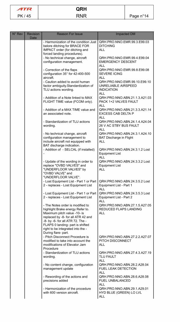
N° Rev RevisionDate
Reason For Issue Impacted DM
- Harmonization of the condition Justbelore ditching for BRACE FORIMPACT order (for ditching andforced landing procedures).
QRH.PRO.NNO.EMR.99.3.E99.03DITCHINGALL
- No technical change, aircraftconfiguration management.
QRH.PRO.NNO.EMR.99.4.E99.04EMERGENCY DESCENTALL
- Correction of the flapsconfiguration 35° for 42-400-500aircraft.
QRH.PRO.NNO.EMR.99.8.E99.08SEVERE ICINGALL
- Caution added to avoid humanfactor ambiguity.Standardization ofTLU actions wording.
QRH.PRO.NNO.EMR.99.10.E99.10UNRELIABLE AIRSPEEDINDICATIONALL
- Addition of a Note linked to MAXFLIGHT TIME value (FCOM only).
QRH.PRO.NNO.ABN.21.1.3.A21.03PACK 1+2 VALVES FAULTALL
- Addition of a MAX TIME value andan associated note.
QRH.PRO.NNO.ABN.21.3.3.A21.14EXCESS CAB DELTA PALL
- Standardization of TLU actionswording.
QRH.PRO.NNO.ABN.24.1.4.A24.0426 V AC STBY BUS FAULTALL
- No technical change, aircraftconfiguration management toinclude aircraft not equipped withBAT discharge indication.
QRH.PRO.NNO.ABN.24.3.1.A24.10BAT Discharge in FlightALL
- Addition of - SELCAL (if installed)-
QRH.PRO.NNO.ABN.24.3.1.2 LostEquipment ListALL
- Update of the wording in order toreplace "OVBD VALVES" and"UNDERFLOOR VALVES" by"OVBD VALVE" and"UNDERFLOOR VALVE".
QRH.PRO.NNO.ABN.24.3.3.2 LostEquipment ListALL
- Lost Equipment List - Part 1 or Part2 - replaces - Lost Equipment List
QRH.PRO.NNO.ABN.24.3.5.2 LostEquipment List - Part 1ALL
- Lost Equipment List - Part 1 or Part2 - replaces - Lost Equipment List
QRH.PRO.NNO.ABN.24.3.5.3 LostEquipment List - Part 2ALL
- The Notes order is modified tohighlight Brake energy Refer to.Maximum pitch value -10- isreplaced by -8- for all ATR 42 and-8- by -6- for all ATR 72. The -FLAPS 0 landing- part is shiftedright to be integrated into the -During flare- part.
QRH.PRO.NNO.ABN.27.1.5.A27.05REDUCED FLAPS LANDINGALL
- Pitch Disconnect Procedure ismodified to take into account themodifications of Elevator JamProcedure
QRH.PRO.NNO.ABN.27.2.2.A27.07PITCH DISCONNECTALL
- Standardization of TLU actionswording.
QRH.PRO.NNO.ABN.27.4.3.A27.19TLU FAULTALL
- No content change, configurationmanagement update
QRH.PRO.NNO.ABN.28.2.A28.04FUEL LEAK DETECTIONALL
- Rewording of the actions andprecisions added
QRH.PRO.NNO.ABN.28.6.A28.08FUEL UNBALANCEDALL
- Harmonization of the procedurewith 600 version aircraft.
QRH.PRO.NNO.ABN.29.1.A29.01HYD BLUE (GREEN) LO LVLALL
QRHPK / 45 RNR Page n°14

N° Rev RevisionDate
Reason For Issue Impacted DM
- Replace maximum pitch value -10by -8- for all ATR 42 and -8- by -6-for all ATR 72. Addition of enginepower guidance (from REDUCEDFLAP LANDING procedure) forlanding with flaps 0°.
QRH.PRO.NNO.ABN.29.5.A29.05HYD BLUE AND GREEN SYSLOSSALL
- Amendment of the secondcondition for clarification purpose.
QRH.PRO.NNO.ABN.30.2.1.A30.05AFR AIR BLEED FAULTALL
- Homogenization and clarification ofthe PROBES HTG FAILUREprocedure in order to avoid flightcrew misunderstanding.
QRH.PRO.NNO.ABN.30.4.1.A30.11PROBES HTG FAILUREALL
- Addition of icing conditions andspeed monitorings, in the absenceof APM
QRH.PRO.NNO.ABN.30.5.1.A30.14APM FAULTALL
- Standardization of turbo fanwording (FCOM only).
QRH.PRO.NNO.ABN.31.1.2.A31.02MFC 1B FAULTALL
- Transfer of TURBOFAN fromEngine chapter into TURBO FAN inAir Chapter.
QRH.PRO.NNO.ABN.31.1.2.2 LostEquipment ListALL
- Standardization of turbo fanwording (FCOM only).
QRH.PRO.NNO.ABN.31.1.4.A31.04MFC 2B FAULTALL
- Transfer of TURBOFAN fromEngine chapter into TURBO FAN inAir Chapter.
QRH.PRO.NNO.ABN.31.1.4.2 LostEquipment ListALL
- Standardization of turbo fanwording (FCOM only).
QRH.PRO.NNO.ABN.31.2.1.A31.05MFC 1A+1B FAULTALL
- Transfer of TURBOFAN fromEngine chapter into TURBO FAN inAir Chapter.
QRH.PRO.NNO.ABN.31.2.1.2 LostEquipment ListALL
- Standardization of TLU actionswording.
QRH.PRO.NNO.ABN.31.2.2.A31.06MFC 1A+2A FAULTALL
- Addition of the LDG GEARPRIMARY GREEN ARROWS in theinoperative system list.
QRH.PRO.NNO.ABN.31.2.2.2 LostEquipment ListALL
- Standardization of turbo fanwording (FCOM only).
QRH.PRO.NNO.ABN.31.2.3.A31.07MFC 1A+2B FAULTALL
- Standardization of turbo fanwording (FCOM only).
QRH.PRO.NNO.ABN.31.2.4.A31.08MFC 1B+2A FAULTALL
- Standardization of turbo fanwording (FCOM only).
QRH.PRO.NNO.ABN.31.2.5.A31.09MFC 1B+2B FAULTALL
- Correction of the commentassociated with LDG GEARlever ...DOWN procedure line forclarification purpose (FCOM only).
QRH.PRO.NNO.ABN.32.5.A32.05LDG GEAR UNSAFE INDICATIONALL
- No content change, proceduremoved to the AFM for certificationconstraints
QRH.PRO.NNO.ABN.32.6.A32.06LANDING WITH ABNORMAL LDGGEARALL
- Update of the procedure andremoval of the condition during taxi -If bleed leak persists- in order tocomply with MMEL 21-50-01limitations.
QRH.PRO.NNO.ABN.36.1.A36.02BLEED LEAK 1(2)ALL
- -REVERSE : NOT AVAILABLE- isreplaced by -REVERSE : DO NOTUSE- for harmonization purpose.
QRH.PRO.NNO.ABN.70.1.4.A70.05PEC 1(2) FAULTALL
QRHPK / 45 RNR Page n°15

N° Rev RevisionDate
Reason For Issue Impacted DM
- Add BLEED VALVE (affected eng)……….. OFF AS RQRD forharmonization purpose with ECL.
QRH.PRO.NNO.ABN.70.3.5.A70.17ENG 1(2) OVER LIMITALL
- No content change, proceduremoved to the AFM for certificationconstraints
QRH.PRO.NNO.ABN.99.1.2.A99.02DOORS UNLK IN FLIGHTALL
- Addition of -HARNESS...CHECKFASTENED & ADJUSTED-procedure line and CAUTION forcrew awareness.
QRH.PRO.NNO.ABN.99.2.1.A99.05COCKPIT WINDOW CRACKEDALL
- No content change, proceduremoved to the AFM for certificationconstraints
QRH.PRO.NNO.ABN.99.2.1.A99.06VOLCANIC ASH ENCOUNTERALL
- Addition of the PBE in theEmergency Equipment list (FCOMonly).
QRH.PRO.NOP.NOR.4.1 InitialInterior ChecksALL
- Update of the content in order toreplace - CHECK STATE - by -CHECK - response for all lightsilluminated and harmonization of thecontent.
QRH.PRO.NOP.NOR.5 ExternalInspectionALL
- Standardization of TLU actionswording.
QRH.PRO.NOP.NOR.6.2 OverheadPanelALL
- No technical change, aircraftconfiguration management.
QRH.PRO.NOP.NOR.14 BeforeTakeoffALL
- Update of the content in order toapply - Reaching 70kt part and PL1+2....RELEASE - action by CAPT-F/O.
QRH.PRO.NOP.NOR.15 TakeoffALL
- No content change, configurationmanagement updated
QRH.PRO.NOP.NOR.17 Climb -CruiseALL
- Standardization of TLU actionswording.Update of the note in orderto give more information at lowengine power.
QRH.PRO.NOP.NOR.21 BeforeLandingALL
- Link updated: FCOM-PER 6-Cruise icing Icing Conditionsreplaces PER.1.3.2.01 Cruise(FCOM only)
QRH.PRO.NOP.ICE.2 Procedure forIcing ConditionsALL
- Addition of a recommendation toprotect the feathering pumps fromdamage.
QRH.PRO.SYSTEM TEST.29.3ATPCS Static TestALL
- Link updated: FCOM-PER 6-Cruise icing Icing Conditionsreplaces PER.1.3.2.01 Cruise(FCOM only)
QRH.ICE.1.2 Procedure for IcingConditionsALL
- Correction of the flapsconfiguration 35° for 42-400-500aircraft.
QRH.ICE.6.E99.08 SEVERE ICINGALL
- Indicate values above MAX FL 200in grey text color in accordance withPack FAULT Limitation.
QRH.PER.4.1.1 Single EngineGross Ceiling - Normal ConditionsALL
- Indicate values above MAX FL 200in grey text color in accordance withPack FAULT Limitation.
QRH.PER.4.2.01 Single EngineGross Ceiling - Icing ConditionsALL
- Create DM in order to split US andSi unit.
QRH.PER.6.1.1 Runway StatusALL
- Deletion of WINDSHIELD HTGOFF action. Configurationmanagement update.
QRH.NCL.1.11 AFTER LANDINGALL
29.0 JUN 21- No technical change, aircraftconfiguration update
QRH.OEB.25 Propeller Blade PitchChange Mechanism Damage (R)ALL
QRHPK / 45 RNR Page n°16
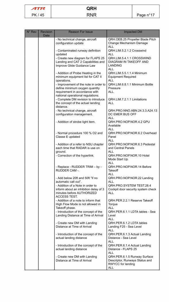
N° Rev RevisionDate
Reason For Issue Impacted DM
- No technical change, aircraftconfiguration update
QRH.OEB.25 Propeller Blade PitchChange Mechanism DamageALL
- Contaminated runway definitionupdated
QRH.LIM.5.2.1.2 CrosswindALL
- Create new diagram for FLAPS 25Landing and CAT 2 Capabilities andImprove Glide Guidance Law
QRH.LIM.5.4.1.1 CROSSWINDDIAGRAM IN TAKEOFF ANDLANDINGALL
- Addition of Probe Heating in theminimum equipment list for CAT IIoperations.
QRH.LIM.5.5.1.1.4 MinimumEquipment RequiredALL
- Improvement of the note in order todefine minimum oxygen quantityrequirement in accordance withnational operational regulations.
QRH.LIM.6.8.1.1 Minimum BottlePressureALL
- Complete DM revision to introducethe concept of the actuel landingdistance.
QRH.LIM.7.2.1.1 LimitationsALL
- No technical change, aircraftconfiguration management.
QRH.PRO.NNO.ABN.24.3.3.A24.13DC EMER BUS OFFALL
- Addition of strobe light item. QRH.PRO.NOP.NOR.4.2 GPUAvailableALL
- Normal procedure 100 % O2 andClasse E updated
QRH.PRO.NOP.NOR.6.2 OverheadPanelALL
- Addition of a refer to NSU chaptereach time that RADAR is use onground.
QRH.PRO.NOP.NOR.6.3 Pedestaland Central PanelsALL
- Correction of the hyperlink. QRH.PRO.NOP.NOR.10 HotelMode Start UpALL
- Replace - RUDDER TRIM – by -RUDDER CAM -.
QRH.PRO.NOP.NOR.14 BeforeTakeoffALL
- Add below 20ft and 50ft "if noautomatic call out".
QRH.PRO.NOP.NOR.22 LandingALL
- Addition of a Note in order toinform about an inhibition delay of 3minutes before AUTHORIZEDACCESS TEST.
QRH.PRO.SYSTEM TEST.28.4Cockpit door security system checkALL
- Addition of a note to inform thatHigh Flow Mode is not allowed inTakeoff phase.
QRH.PER.2.2.1 Reserve TakeoffTorqueALL
- Introduction of the concept of theLanding Distance at Time of Arrival
QRH.PER.6.1.1 LDTA tables - SeaLevelALL
- Create new DM with LandingDistance at Time of Arrival
QRH.PER.6.1.2 LDTA tablesLanding F25 - Sea LevelALL
- Introduction of the concept of theactual landing distance
QRH.PER.6.1.3 Actual LandingDistance - Sea LevelALL
- Introduction of the concept of theactual landing distance
QRH.PER.6.1.4 Actual LandingDistance - FLAPS 25ALL
- Create new DM with LandingDistance at Time of Arrival
QRH.PER.6.1.5 Runway SurfaceDescriptor, Runways Status andRWYCC for landingALL
QRHPK / 45 RNR Page n°17

PAGE
INTENTIONALLY
LEFT BLANK
QRHPK / 45 RNR Page n°18
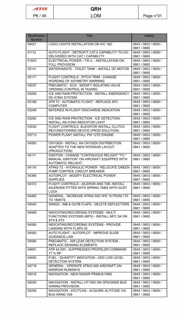
ModificationNumber
Title Validity
00021 LOGO LIGHTS INSTALLATION ON A/C 1&2. 0645 / 0653 / 0659 /0661 / 0665
01112 AUTO FLIGHT - RETROFIT CAT.2 CAPABILITY TO A/CDELIVERED WITH CAT.1 CAPABILITY.
0645 / 0653 / 0659 /0661 / 0665
01603 ELECTRICAL POWER - T.R.U. - INSTALLATION ONFULL PROVISION
0645 / 0653 / 0659 /0661 / 0665
02141 WATER/WASTE - TOILET TANK - INSTALL DC MOTOR 0645 / 0653 / 0659 /0661 / 0665
02171 FLIGHT CONTROLS - PITCH TRIM - CHANGEWORDING OF ASYMETRY WARNING
0645 / 0653 / 0659 /0661 / 0665
03037 PNEUMATIC - ECS - MODIFY ISOLATING VALVEOPENING CONTROL IN TAXIING
0645 / 0653 / 0659 /0661 / 0665
03059 ICE AND RAIN PROTECTION - INSTALL EMERGENCYDE-ICING SYSTEM
0645 / 0653 / 0659 /0661 / 0665
03168 ATR 72 - AUTOMATIC FLIGHT - REPLACE AFCCOMPUTER
0645 / 0653 / 0659 /0661 / 0665
03246 BATERIES IN-FLIGHT DISCHARGE INDICATION 0645 / 0653 / 0659 /0661 / 0665
03262 ICE AND RAIN PROTECTION - ICE DETECTION-INSTALL AN ICING INDICATOR LIGHT
0645 / 0653 / 0659 /0661 / 0665
03530 FLIGHT CONTROLS -ELEVATOR INSTALL CLUTCHRECONDITIONING DEVICE (PROD.SOLUTION)
0645 / 0653 / 0659 /0661 / 0665
03713 POWER PLANT: INSTALL PW 127E ENGINE 0645 / 0653 / 0659 /0661 / 0665
04083 OXYGEN - INSTALL AN OXYGEN DISTRIBUTIONADAPTED TO THE NEW INTERIOR LAYOUT(PRODUCTION)
0645 / 0653 / 0659 /0661 / 0665
04111 IGNITION - CHANGE "CONTINUOUS RELIGHT "TO "MANUAL IGNITION" ON AIRCRAFT EQUIPPED WITHAUTOMATIC RELIGHT.
0645 / 0653 / 0659 /0661 / 0665
04116 ATR42-72 - HYDRAULIC POWER - RELOCATE GREENPUMP CONTROL CIRCUIT BREAKER
0645 / 0653 / 0659 /0661 / 0665
04366 AUTOPILOT - MODIFY ELECTRICAL POWERSUPPLIES
0645 / 0653 / 0659 /0661 / 0665
04372 FLIGHT CONTROLS - AILERON AND TAB -INSTALLAILERONS FITTED WITH SPRING TABS WITH GUSTLOCK
0645 / 0653 / 0659 /0661 / 0665
04462 GENERAL - INCREASE ATR42-500 VFE 15 FROM 170TO 180KTS.
0645 / 0653 / 0659 /0661 / 0665
04540 WINGS - INB & OUTB FLAPS - DELETE DEFLECTORS 0645 / 0653 / 0659 /0661 / 0665
04569 INDICATING/RECORDING SYSTEMS - MULTIFUNCTIONS SYSTEMS (MFS) - INSTALL MFC S4 ONST4 & ST5
0645 / 0653 / 0659 /0661 / 0665
04580 INDICATING/RECORDING SYSTEMS - PROVIDELANDING WITH FLAPS 25
0645 / 0653 / 0659 /0661 / 0665
04583 AUTO FLIGHT - AUTOPILOT - IMPROVE GLIDEGUIDANCE LAW
0645 / 0653 / 0659 /0661 / 0665
04584 PNEUMATIC - AIR LEAK DETECTION SYSTEM -REPLACE SENSING ELEMENTS
0645 / 0653 / 0659 /0661 / 0665
04601 ATR 42-500 - SUPPRESSED PROPELER COMMAND77 % NP
0645 / 0653 / 0659 /0661 / 0665
04650 FUEL - QUANTITY INDICATION - ADD LOW LEVELDETECTION SYSTEM.
0645 / 0653 / 0659 /0661 / 0665
04718 GENERAL - OPERATE ATR42-500 AIRCRAFT ONNARROW RUNWAYS
0645 / 0653 / 0659 /0661 / 0665
05016 NAVIGATION - NEW RADAR PRIMUS P660 0645 / 0653 / 0659 /0661 / 0665
05020 NAVIGATION - INSTALL HT1000 ON GPS/GNSS BUSWIRING PROVISION
0645 / 0653 / 0659 /0661 / 0665
05205 NAVIGATION - ATC/TCAS - ACQUIRE ALTITUDE VIABUS ARINC 429
0645 / 0653 / 0659 /0661 / 0665
QRHPK / 45 LOM Page n°01
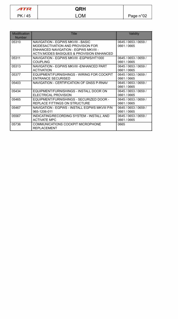
ModificationNumber
Title Validity
05310 NAVIGATION - EGPWS MKVIII - BASICMODESACTIVATION AND PROVISION FORENHANCED NAVIGATION - EGPWS MKVIII -ACTIV.MODES BASIQUES & PROVISION ENHANCED
0645 / 0653 / 0659 /0661 / 0665
05311 NAVIGATION - EGPWS MKVIII -EGPWS/HT1000COUPLING
0645 / 0653 / 0659 /0661 / 0665
05313 NAVIGATION - EGPWS MKVIII -ENHANCED PARTACTIVATION
0645 / 0653 / 0659 /0661 / 0665
05377 EQUIPMENT/FURNISHINGS - WIRING FOR COCKPITENTRANCE SECURISED
0645 / 0653 / 0659 /0661 / 0665
05403 NAVIGATION - CERTIFICATION OF GNSS P-RNAV 0645 / 0653 / 0659 /0661 / 0665
05434 EQUIPMENT/FURNISHINGS - INSTALL DOOR ONELECTRICAL PROVISION
0645 / 0653 / 0659 /0661 / 0665
05465 EQUIPMENT/FURNISHINGS - SECURIZED DOOR -REPLACE FITTINGS ON STRUCTURE
0645 / 0653 / 0659 /0661 / 0665
05467 NAVIGATION - EGPWS - INSTALL EGPWS MKVIII P/N965-1206-011
0645 / 0653 / 0659 /0661 / 0665
05567 INDICATING/RECORDING SYSTEM - INSTALL ANDACTIVATE MPC
0645 / 0653 / 0659 /0661 / 0665
05736 COMMUNICATIONS COCKPIT MICROPHONEREPLACEMENT
0665
QRHPK / 45 LOM Page n°02
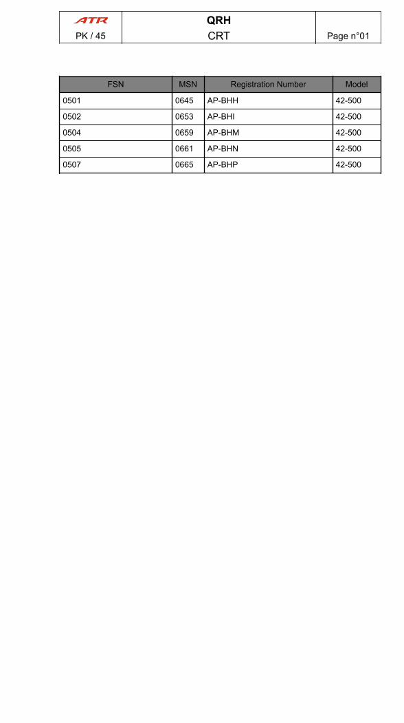
FSN MSN Registration Number Model
0501 0645 AP-BHH 42-500
0502 0653 AP-BHI 42-500
0504 0659 AP-BHM 42-500
0505 0661 AP-BHN 42-500
0507 0665 AP-BHP 42-500
QRHPK / 45 CRT Page n°01
PAGE
INTENTIONALLY
LEFT BLANK
QRHPK / 45 CRT Page n°02
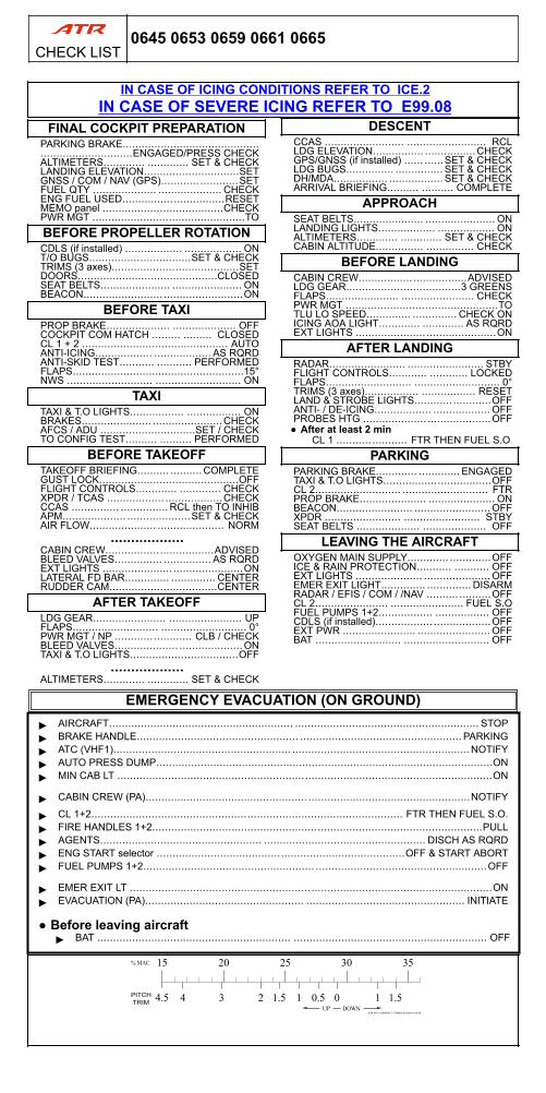
IN CASE OF ICING CONDITIONS REFER TO ICE.2IN CASE OF SEVERE ICING REFER TO E99.08
FINAL COCKPIT PREPARATIONPARKING BRAKE........................................................................ENGAGED/PRESS CHECKALTIMETERS............. ............. SET & CHECKLANDING ELEVATION..............................SETGNSS / COM / NAV (GPS)............ ............SETFUEL QTY .................... .................... CHECKENG FUEL USED................................RESETMEMO panel ......................................CHECKPWR MGT ................................................TOBEFORE PROPELLER ROTATIONCDLS (if installed) .................. .................. ONT/O BUGS................................SET & CHECKTRIMS (3 axes)........................................SETDOORS............................................CLOSEDSEAT BELTS...................... ...................... ONBEACON......................... .........................ON
BEFORE TAXIPROP BRAKE.................... .................... OFFCOCKPIT COM HATCH ......... ......... CLOSEDCL 1 + 2 .............................................. AUTOANTI-ICING.................. .................. AS RQRDANTI-SKID TEST........... ........... PERFORMEDFLAPS......................................................15°NWS ........................... ........................... ON
TAXITAXI & T.O LIGHTS................. ................. ONBRAKES...................... ......................CHECKAFCS / ADU ..............................SET / CHECKTO CONFIG TEST.......... .......... PERFORMED
BEFORE TAKEOFFTAKEOFF BRIEFING.......... ..........COMPLETEGUST LOCK............................................OFFFLIGHT CONTROLS............. ............. CHECKXPDR / TCAS .................. ..................CHECKCCAS ............... ............... RCL then TO INHIBAPM.................... ....................SET & CHECKAIR FLOW..................... ..................... NORM
..................CABIN CREW..................................ADVISEDBLEED VALVES............... ............... AS RQRDEXT LIGHTS ............................................ONLATERAL FD BAR.............. .............. CENTERRUDDER CAM..................................CENTER
AFTER TAKEOFFLDG GEAR....................... ....................... UPFLAPS........................... ........................... 0°PWR MGT / NP ........................ CLB / CHECKBLEED VALVES.................... ....................ONTAXI & T.O LIGHTS..................................OFF
..................ALTIMETERS............. ............. SET & CHECK
DESCENTCCAS ......................... ......................... RCLLDG ELEVATION................ ................CHECKGPS/GNSS (if installed) ...... ......SET & CHECKLDG BUGS............... ............... SET & CHECKDH/MDA................. ................. SET & CHECKARRIVAL BRIEFING.......... .......... COMPLETE
APPROACHSEAT BELTS...................... ...................... ONLANDING LIGHTS.................. .................. ONALTIMETERS............. ............. SET & CHECKCABIN ALTITUDE............... ............... CHECK
BEFORE LANDINGCABIN CREW..................................ADVISEDLDG GEAR....................................3 GREENSFLAPS....................... ....................... CHECKPWR MGT ................................................TOTLU LO SPEED.............. .............. CHECK ONICING AOA LIGHT............. ............. AS RQRDEXT LIGHTS ............................................ON
AFTER LANDINGRADAR........................ ........................ STBYFLIGHT CONTROLS............ ............ LOCKEDFLAPS........................... ........................... 0°TRIMS (3 axes)................. ................. RESETLAND & STROBE LIGHTS........................OFFANTI- / DE-ICING.................. .................. OFFPROBES HTG .................... ....................OFF
● After at least 2 minCL 1 ........... ........... FTR THEN FUEL S.O
PARKINGPARKING BRAKE............. ............. ENGAGEDTAXI & T.O LIGHTS..................................OFFCL 2........................... ........................... FTRPROP BRAKE..................... ..................... ONBEACON........................ ........................ OFFXPDR ........................ ........................ STBYSEAT BELTS .................... .................... OFF
LEAVING THE AIRCRAFTOXYGEN MAIN SUPPLY............. .............OFFICE & RAIN PROTECTION........... ........... OFFEXT LIGHTS ..................... ..................... OFFEMER EXIT LIGHT.............. .............. DISARMRADAR / EFIS / COM / /NAV .......... ..........OFFCL 2....................... ....................... FUEL S.OFUEL PUMPS 1+2................. ................. OFFCDLS (if installed).................. ..................OFFEXT PWR ....................... ....................... OFFBAT ........................... ........................... OFF
EMERGENCY EVACUATION (ON GROUND)▶ AIRCRAFT.......................................................... .......................................................... STOP▶ BRAKE HANDLE................................................... ................................................... PARKING▶ ATC (VHF1)........................................................ ........................................................NOTIFY▶ AUTO PRESS DUMP..........................................................................................................ON▶ MIN CAB LT ......................................................................................................................ON
▶ CABIN CREW (PA)................................................... ...................................................NOTIFY
▶ CL 1+2.................................................................................................. FTR THEN FUEL S.O.▶ FIRE HANDLES 1+2........................................................................................................PULL▶ AGENTS................................................... ................................................... DISCH AS RQRD▶ ENG START selector ..............................................................................OFF & START ABORT▶ FUEL PUMPS 1+2...................................................... ......................................................OFF
▶ EMER EXIT LT ..................................................................................................................ON▶ EVACUATION (PA).................................................. .................................................. INITIATE
● Before leaving aircraft▶ BAT ............................................................. ............................................................. OFF
ICN-45-Y-000000-T-FB429-01024-A-0 -N3
4.5 4 3 2 1.5 1
15 20 25 30 35% MAC
PITCH TRIM
UP DOWN1 0.5 0 1.5
0645 0653 0659 0661 0665CHECK LIST
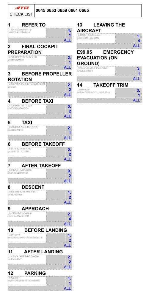
1 REFER TO_15c43d03-bdac-4f7b-bc03-054b37844ad5 4.
1ALL
2 FINAL COCKPITPREPARATION_8778c14b-f493-4332-9408-b0d8dc49987d 2.
1ALL
3 BEFORE PROPELLERROTATION_e3957567-91e3-4a1b-92d4-8266689cfab4 2.
2ALL
4 BEFORE TAXI_40d557cb-1177-4aa3-a060-3f24129d0f5a 0.
2ALL
5 TAXI_0a763bb8-7ea9-494f-82d5-aa9e058fa01c 2.
1ALL
6 BEFORE TAKEOFF_d577fb20-765d-4363-a401-670917d378f4 0.
2ALL
7 AFTER TAKEOFF_833bf95d-0d06-4034-bb0c-16c40ff257a5 0.
2ALL
8 DESCENT_ce3e35f6-e2bd-4d0f-9847-eb563d2ff5a6 1.
2ALL
9 APPROACH_be3f1bd1-01b8-45e7-b3eb-44d1ae249fd1 2.
4ALL
10 BEFORE LANDING_2b446849-ad12-4522-9c4d-181ab958ab33 1.
2ALL
11 AFTER LANDING_1ac2a5e1-0273-4e92-aa9a-ea16afe4fb81 2.
2ALL
12 PARKING_639a3787-a93f-40f8-9d83-997e3eef59b0 1.
1ALL
13 LEAVING THEAIRCRAFT_b1099b19-daf3-44fc-ad05-734619ee550a 1.
4ALL
E99.05 EMERGENCYEVACUATION (ONGROUND)_9d94a5cb-a461-49e5-9ebb-d233509dc7d4 3.
1ALL
14 TAKEOFF TRIM_236b1539-ea3b-4715-92e7-1cbf605c89ce 3.
1ALL
0645 0653 0659 0661 0665CHECK LIST