QoS Best Practices - cisco.com · QoS Best Practices Tim Szigeti ... Quality of Service High...
89
1 © 2004 Cisco Systems, Inc. All rights reserved. IP07 QoS QoS Best Practices Tim Szigeti Technical Marketing Engineer Technology and Systems Marketing: QoS Cisco Central Development Organization 10/5/04
Transcript of QoS Best Practices - cisco.com · QoS Best Practices Tim Szigeti ... Quality of Service High...

1© 2004 Cisco Systems, Inc. All rights reserved.IP07 QoS
QoS Best Practices
Tim SzigetiTechnical Marketing EngineerTechnology and Systems Marketing: QoSCisco Central Development Organization10/5/04

222© 2004 Cisco Systems, Inc. All rights reserved.IP07 QoS
QoS PerceptionChanging the Way Intelligent Services Are Enabled
Quality ofService
Quality ofService
High AvailabilityHigh Availability
SecuritySecurity
Necessity Luxury

3© 2004 Cisco Systems, Inc. All rights reserved.IP07 QoS
QoS Deployment Principles

444© 2004 Cisco Systems, Inc. All rights reserved.IP07 QoS
1) Strategically define the business objectives to be achieved via QoS.
2) Analyze the service-level requirements of the various traffic classes to be provisioned for.
3) Design and test the QoS policies prior to production-network rollout.
4) Roll-out the tested QoS designs to the production-network in phases, during scheduled downtime.
5) Monitor service levels to ensure that the QoS objectives are being met.
How is QoS Optimally Deployed in the Enterprise?
555© 2004 Cisco Systems, Inc. All rights reserved.IP07 QoS
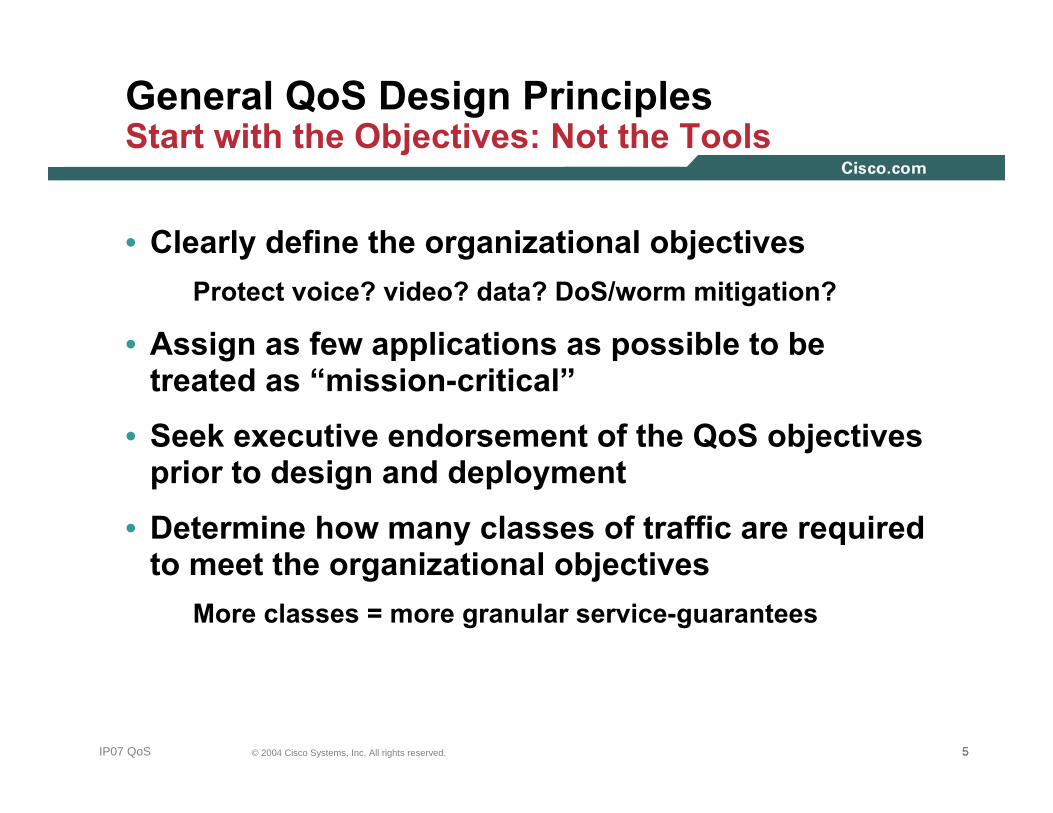
General QoS Design PrinciplesStart with the Objectives: Not the Tools
• Clearly define the organizational objectives Protect voice? video? data? DoS/worm mitigation?
• Assign as few applications as possible to be treated as “mission-critical”
• Seek executive endorsement of the QoS objectives prior to design and deployment
• Determine how many classes of traffic are required to meet the organizational objectives
More classes = more granular service-guarantees
666© 2004 Cisco Systems, Inc. All rights reserved.IP07 QoS
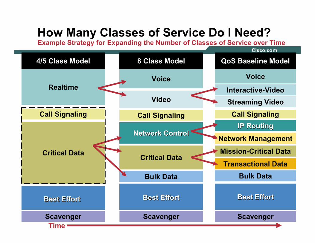
How Many Classes of Service Do I Need?Example Strategy for Expanding the Number of Classes of Service over Time
4/5 Class Model
Scavenger
Critical Data
Call Signaling
Best EffortBest Effort
Realtime
8 Class Model
Critical Data
Video
Call Signaling
Best EffortBest Effort
Voice
Bulk Data
Network ControlNetwork Control
Scavenger
QoS Baseline Model
Network Management
Call SignalingStreaming Video
Transactional Data
Interactive-Video
Voice
Best EffortBest Effort
IP RoutingIP Routing
Mission-Critical Data
Scavenger
Bulk Data
Time

QOS REQUIREMENTS OF VOICE, VIDEO, AND DATA
777© 2004 Cisco Systems, Inc. All rights reserved.NMS-2T309681_05_2004_c2
888© 2004 Cisco Systems, Inc. All rights reserved.IP07 QoS
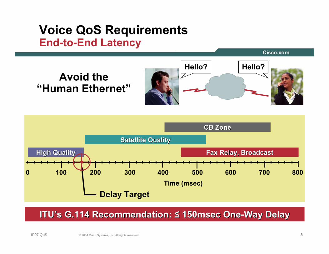
Voice QoS RequirementsEnd-to-End Latency
Delay Target
Avoid the “Human Ethernet”
Time (msec)0 100 200 300 400
CB ZoneCB Zone
Satellite QualitySatellite Quality
Fax Relay, BroadcastFax Relay, BroadcastHigh QualityHigh Quality
500 600 700 800
ITUITU’’s G.114 Recommendation: s G.114 Recommendation: ≤≤ 150msec One150msec One--Way DelayWay Delay
Hello? Hello?

999© 2004 Cisco Systems, Inc. All rights reserved.IP07 QoS
Voice QoS RequirementsElements That Affect Latency and Jitter
Campus Branch Office
IP WAN
PSTN
EndEnd--toto--End Delay (Must Be End Delay (Must Be ≤≤ 150 ms)150 ms)
20–50 ms
Jitter Buffer
FixedFixed(6.3 (6.3 µµs/Km) +s/Km) +
Network DelayNetwork Delay(Variable)(Variable)
PropagationPropagationand Networkand Network
Variable
Serialization
VariableVariable
QueuingQueuing
G.729A: 25 msG.729A: 25 ms
CODECCODEC
101010© 2004 Cisco Systems, Inc. All rights reserved.IP07 QoS
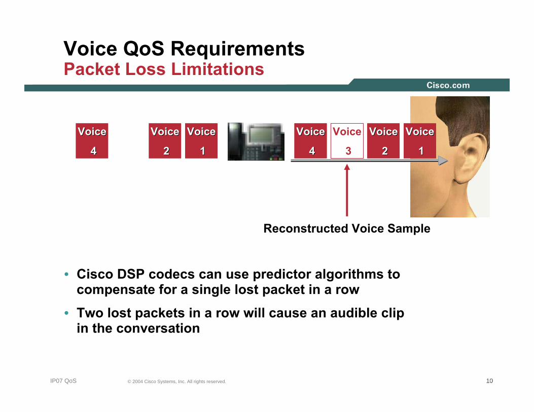
Voice QoS RequirementsPacket Loss Limitations
• Cisco DSP codecs can use predictor algorithms to compensate for a single lost packet in a row
• Two lost packets in a row will cause an audible clip in the conversation
VoiceVoice
11
VoiceVoice
22
Voice
3
VoiceVoice
44
VoiceVoice
11
VoiceVoice
22
Voice
3
Voice
3
VoiceVoice
44
Voice
3
Voice
3
Voice
3
Voice
3 Reconstructed Voice Sample

111111© 2004 Cisco Systems, Inc. All rights reserved.IP07 QoS
Voice QoS RequirementsCall Admission Control (CAC): Why Is It Needed?
IP WAN/VPN
Router/Gateway
CiscoCall
Manager
PSTN
CircuitCircuit--Switched Switched NetworksNetworks
PacketPacket--Switched Switched NetworksNetworks
PBX
PhysicalTrunks
STOPSTOP
IP VPN Link Provisionedfor 2 VoIP Calls
Third CallRejected
NoNo PhysicalPhysicalLimitation on IP LinksLimitation on IP Links
If 3If 3rdrd Call Accepted,Call Accepted,Voice Quality of Voice Quality of AllAll
Calls DegradesCalls Degrades
CAC Limits Number of VoIP Calls on Each VPN LinkCAC Limits Number of VoIP Calls on Each VPN Link

121212© 2004 Cisco Systems, Inc. All rights reserved.IP07 QoS
“P” and “B” Frames128–256 Bytes
“I” Frame1024–1518
Bytes
“I” Frame1024–1518
Bytes
15pps
30pps
450Kbps
32Kbps
Video QoS RequirementsVideo Conferencing Traffic Example (384 kbps)
• “I” frame is a full sample of the video
• “P” and “B” frames use quantization via motion vectors and prediction algorithms
131313© 2004 Cisco Systems, Inc. All rights reserved.IP07 QoS
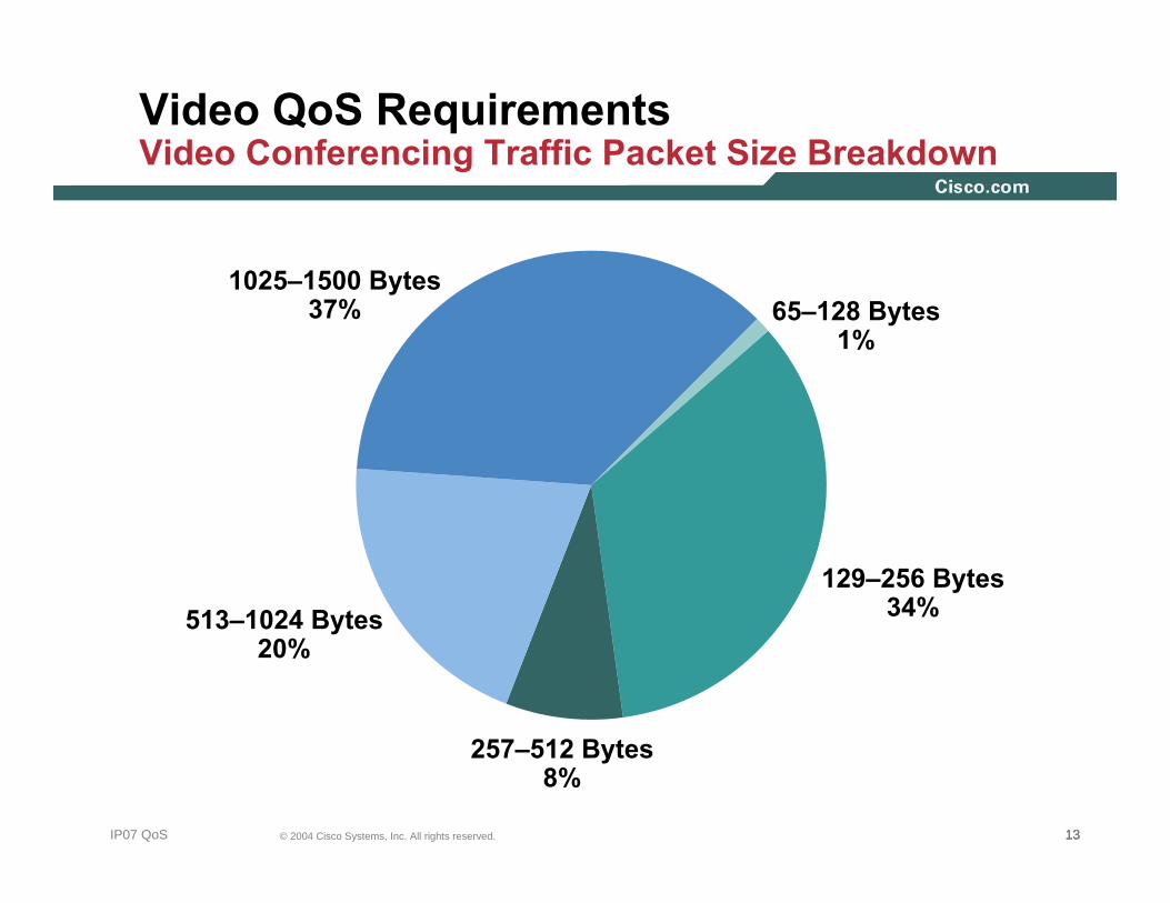
Video QoS RequirementsVideo Conferencing Traffic Packet Size Breakdown
65–128 Bytes 1%
129–256 Bytes 34%513–1024 Bytes
20%
1025–1500 Bytes 37%
257–512 Bytes 8%
141414© 2004 Cisco Systems, Inc. All rights reserved.IP07 QoS
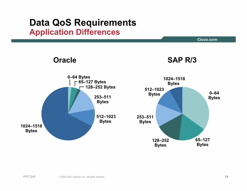
Data QoS RequirementsApplication Differences
Oracle SAP R/3
0–64Bytes
1024–1518Bytes
512–1023Bytes
253–511Bytes
128–252Bytes
65–127Bytes
1024–1518Bytes
512–1023Bytes
253–511Bytes
128–252 Bytes65–127 Bytes
0–64 Bytes

151515© 2004 Cisco Systems, Inc. All rights reserved.IP07 QoS
Data QoS Requirements Version Differences
Client VersionVA01 # of
Bytes
SAP GUI Release 3.0 F 14,000
SAP GUI Release 4.6C, No Cache 57,000
SAP GUI Release 4.6C, with Cache 33,000
SAP GUI for HTML, Release 4.6C 490,000
SAP Sales OrderEntry Transaction
• Same transaction takes over 35 times more traffic from one version of an application to another
0
100,000
200,000
300,000
400,000
500,000
SAP GUI,Release
3.0F
SAP GUI,Release
4.6C, withCache
SAP GUI,Release4.6C, noCache
SAP GUI(HTML),Release
4.6C
OVERVIEW OF DOS/WORM ATTACKS
161616© 2004 Cisco Systems, Inc. All rights reserved.NMS-2T309681_05_2004_c2

171717© 2004 Cisco Systems, Inc. All rights reserved.IP07 QoS
Business Security Threat EvolutionExpanding Scope of Theft and Disruption
Scop
e of
Dam
age
1980’s 1990’s Today Future
IndividualComputer
1st GenBoot Viruses
Sophistication of Threats
Next GenInfrastructure
Hacking, Flash Threats,
Massive Worm Driven DDoS,
Negative Payload Viruses,
Worms and Trojans
GlobalImpact
RegionalNetworks
3rd GenMulti-Server DoS, DDoS,
Blended Threat (Worm+ Virus+ Trojan), Turbo
Worms, Widespread
System Hacking
MultipleNetworks
2nd GenMacro Viruses, Trojans, Email, Single Server DoS, Limited
Targeted Hacking
IndividualNetworks

181818© 2004 Cisco Systems, Inc. All rights reserved.IP07 QoS
Emerging Speed of Network AttacksDo You Have Time To React?
1980s-1990sUsually had Weeks
or Months to Put Defense in Place
2000-2002Attacks ProgressedOver Hours, Time
to Assess Danger and Impact;Time to Implement Defense
2003-FutureAttacks Progress on the
Timeline of Seconds
SQL Slammer Worm:Doubled Every 8.5 SecondsAfter 3 Min: 55M Scans/Sec1Gb Link Is Saturated After
One MinuteIn Half the Time It Took to Read
This Slide, Your Networkand All of Your Applications Would
Have Become UnreachableSQL Slammer Was A Warning,
Newer “Flash” Worms AreExponentially Faster

191919© 2004 Cisco Systems, Inc. All rights reserved.IP07 QoS
“Slammer” or the Sapphire WormInfected 75,000 Hosts in First 11 Minutes
11 Minutes after Release
• Infections doubled every 8.5 seconds• Infected 75,000 hosts in first 11 minutes• Caused network outages, cancelled airline
flights and ATM failures
At Peak, Scanned 55 MillionHosts per Second
At Peak, Scanned 55 MillionHosts per Second
19
26811 0
202020© 2004 Cisco Systems, Inc. All rights reserved.IP07 QoS
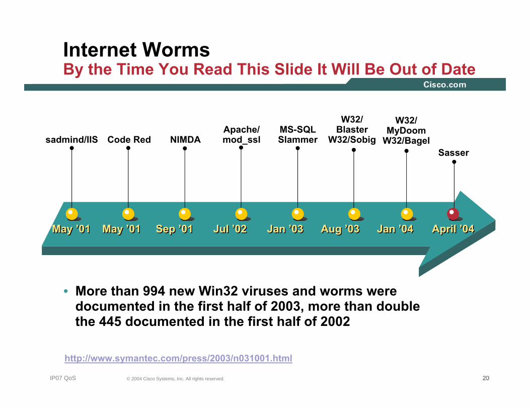
May ’01May ’01 Sep ’01Sep ’01 Jan ’03Jan ’03
Code RedCode Red NIMDANIMDAMS-SQL SlammerMS-SQL Slammer
Aug ’03Aug ’03
W32/Blaster
W32/Sobig
W32/Blaster
W32/Sobig
May ’01May ’01
sadmind/IISsadmind/IIS
Jul ’02Jul ’02
Apache/mod_sslApache/mod_ssl
Jan ’04Jan ’04
W32/MyDoom
W32/Bagel
W32/MyDoom
W32/Bagel
• More than 994 new Win32 viruses and worms were documented in the first half of 2003, more than double the 445 documented in the first half of 2002
http://www.symantec.com/press/2003/n031001.html
SasserSasser
April ’04April ’04
Internet WormsBy the Time You Read This Slide It Will Be Out of Date

212121© 2004 Cisco Systems, Inc. All rights reserved.IP07 QoS
Types of DoS AttacksSpoofing vs. Slamming
• Imposter attackPretends to be a legitimate service but maliciously intercepts/misdirects client requests
• Flooding attackExponentially generates and propagates traffic until service resources (servers and/or network) are overwhelmed
222222© 2004 Cisco Systems, Inc. All rights reserved.IP07 QoS
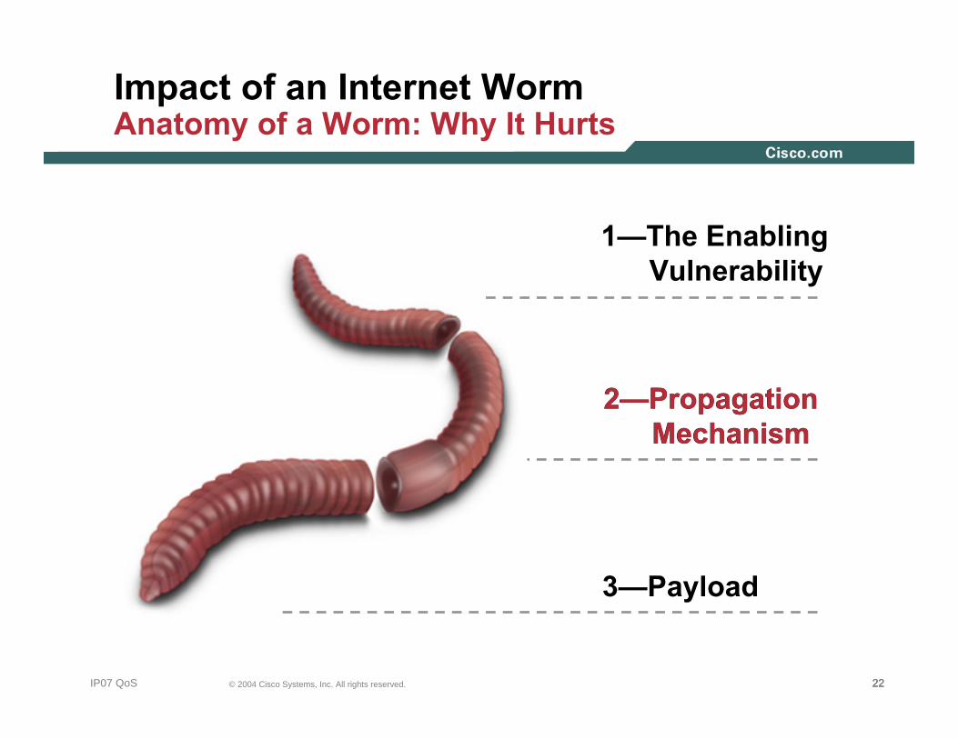
1—The Enabling Vulnerability
Impact of an Internet WormAnatomy of a Worm: Why It Hurts
2—Propagation Mechanism
3—Payload
2—Propagation Mechanism

232323© 2004 Cisco Systems, Inc. All rights reserved.IP07 QoS
Impact of an Internet Worm Direct and Collateral Damage
Attacks Targeted to End Systems CAN and DO Affect the Infrastructure
Access
Distribution
Core
InfectedSource
SiSi
SiSi
SiSi SiSi
SystemUnder Attack
Routers Overloaded
High CPUInstability
Loss of MgmtEnd SystemsOverloaded
High CPUApplications
Impacted
Network Links Overloaded
High Packet LossMission Critical
Applications Impacted

24© 2004 Cisco Systems, Inc. All rights reserved.IP07 QoS
QoS Technologies Review
252525© 2004 Cisco Systems, Inc. All rights reserved.IP07 QoS
QoS Technologies Review
• QoS Overview
• Classification Tools
• Scheduling Tools
• Policing and Shaping Tools
• Link-Specific Tools

262626© 2004 Cisco Systems, Inc. All rights reserved.IP07 QoS
QoS Factors Attributes Requiring Explicit Service Levels
DelayDelay(Latency)(Latency)
DelayDelay--VariationVariation
(Jitter)(Jitter)
PacketPacketLossLoss
272727© 2004 Cisco Systems, Inc. All rights reserved.IP07 QoS
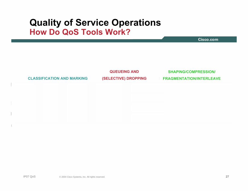
Quality of Service OperationsHow Do QoS Tools Work?
CLASSIFICATION AND MARKING
QUEUEING AND
(SELECTIVE) DROPPING
SHAPING/COMPRESSION/
FRAGMENTATION/INTERLEAVE

282828© 2004 Cisco Systems, Inc. All rights reserved.IP07 QoS
Classification ToolsEthernet 802.1Q Class of Service
• 802.1p user priority field also called Class of Service (CoS)
• Different types of traffic are assigned different CoS values
• CoS 6 and 7 are reserved for network use
TAGTAG4 Bytes4 Bytes
Three Bits Used for CoS(802.1p User Priority)
Data FCSPTSADASFDPream. Type
802.1Q/pHeader
PRIPRI VLAN IDVLAN IDCFICFI
Ethernet Frame
1
2
3
4
5
66
7
00 Best Effort DataBest Effort Data
Bulk Data
Critical Data
Call Signaling
Video
Voice
RoutingRouting
ReservedCoS Application

292929© 2004 Cisco Systems, Inc. All rights reserved.IP07 QoS
Classification ToolsIP Precedence and DiffServ Code Points
• IPv4: Three most significant bits of ToS byte are called IP Precedence (IPP)—other bits unused
• DiffServ: Six most significant bits of ToS byte are called DiffServ Code Point (DSCP)—remaining two bits used forflow control
• DSCP is backward-compatible with IP precedence
77 66 55 44 33 22 11 00
ID Offset TTL Proto FCS IP SA IP DA DataLenVersionLength
ToSToSByteByte
DiffServ Code Point (DSCP)DiffServ Code Point (DSCP) IP ECN
IPv4 Packet
IP PrecedenceIP Precedence UnusedUnusedStandard IPv4
DiffServ Extensions
303030© 2004 Cisco Systems, Inc. All rights reserved.IP07 QoS
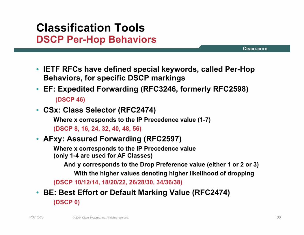
Classification ToolsDSCP Per-Hop Behaviors
• IETF RFCs have defined special keywords, called Per-Hop Behaviors, for specific DSCP markings
• EF: Expedited Forwarding (RFC3246, formerly RFC2598)(DSCP 46)
• CSx: Class Selector (RFC2474)Where x corresponds to the IP Precedence value (1-7)(DSCP 8, 16, 24, 32, 40, 48, 56)
• AFxy: Assured Forwarding (RFC2597)Where x corresponds to the IP Precedence value (only 1-4 are used for AF Classes)
And y corresponds to the Drop Preference value (either 1 or 2 or 3)With the higher values denoting higher likelihood of dropping
(DSCP 10/12/14, 18/20/22, 26/28/30, 34/36/38)
• BE: Best Effort or Default Marking Value (RFC2474)(DSCP 0)

313131© 2004 Cisco Systems, Inc. All rights reserved.IP07 QoS
Classification ToolsNetwork-Based Application Recognition
98 Supported Protocols
DATA
Frame
MAC/CoSDE/CLP/MPLS EV
IP PacketToS/
DSCP
ToS/
DSCPSource
IP
Source
IP
Dest
IP
Dest
IP
TCP/UDPSegment
Src
Port
Src
PortDst
Port
Dst
Port
Data Payload
NBAR PDLMNBAR PDLM
citrix http nntp ssh
cuseeme
custom
exchange
fasttrack
ftp
gnutella
imap
irc
kerberos
ldap
napster
netshow
notes
novadigm
pcanywhere
pop3
realaudio
rcmd
smtp
snmp
socks
sqlserver
sqlnet
sunrpc
streamwork
syslog
telnet
secure-telnet
tftp
vdolive
xwindows

323232© 2004 Cisco Systems, Inc. All rights reserved.IP07 QoS
Policing ToolsRFC 2697 Single Rate Three Color Policer
Action ActionAction
Overflow
B<Tc B<Te
ConformConform Exceed ViolateViolate
CBS EBS
CIR
Yes Yes
No No
ActionAction
Packet ofSize B
333333© 2004 Cisco Systems, Inc. All rights reserved.IP07 QoS
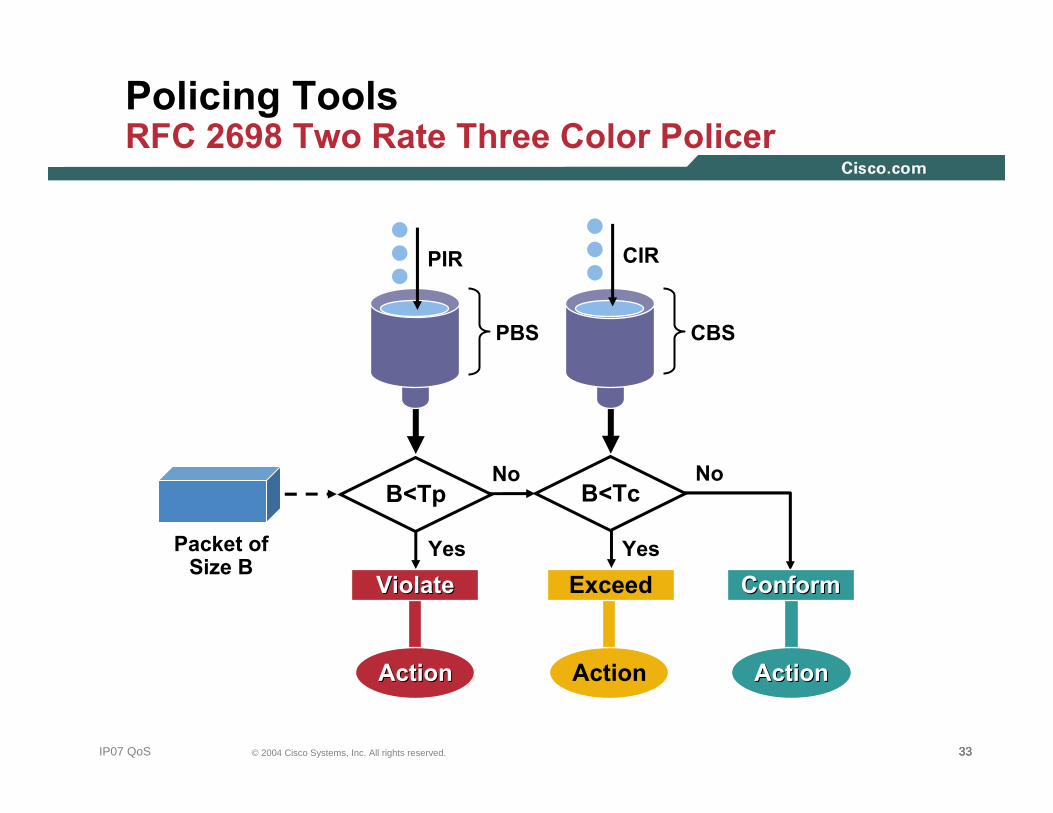
Policing ToolsRFC 2698 Two Rate Three Color Policer
ActionActionAction
B<Tp B<Tc
ExceedViolateViolate
PBS CBS
PIR
Yes Yes
No No
ConformConform
ActionAction
Packet ofSize B
CIR
343434© 2004 Cisco Systems, Inc. All rights reserved.IP07 QoS
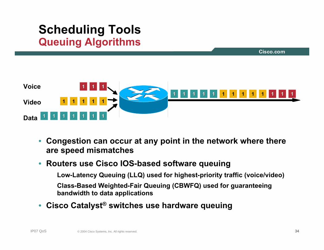
Scheduling ToolsQueuing Algorithms
• Congestion can occur at any point in the network where there are speed mismatches
• Routers use Cisco IOS-based software queuingLow-Latency Queuing (LLQ) used for highest-priority traffic (voice/video)Class-Based Weighted-Fair Queuing (CBWFQ) used for guaranteeing bandwidth to data applications
• Cisco Catalyst® switches use hardware queuing
11 11111 11 1111 11 1111 11Voice
Video
Data33
2 2
1 111 11 11
1 1 1
11 11 11
1 1
11 11 1111

353535© 2004 Cisco Systems, Inc. All rights reserved.IP07 QoS
Time
Bandwidth Utilization100%
Tail Drop
3 Traffic Flows Start at Different Times
Another Traffic FlowStarts at This Point
Scheduling ToolsTCP Global Synchronization: The Need for Congestion Avoidance
All TCP Flows Synchronize inWaves Wasting Much of the Available Bandwidth
363636© 2004 Cisco Systems, Inc. All rights reserved.IP07 QoS
312302021201
TAIL DROP
3
3
3
WRED
01
0
1
0
3
Queue
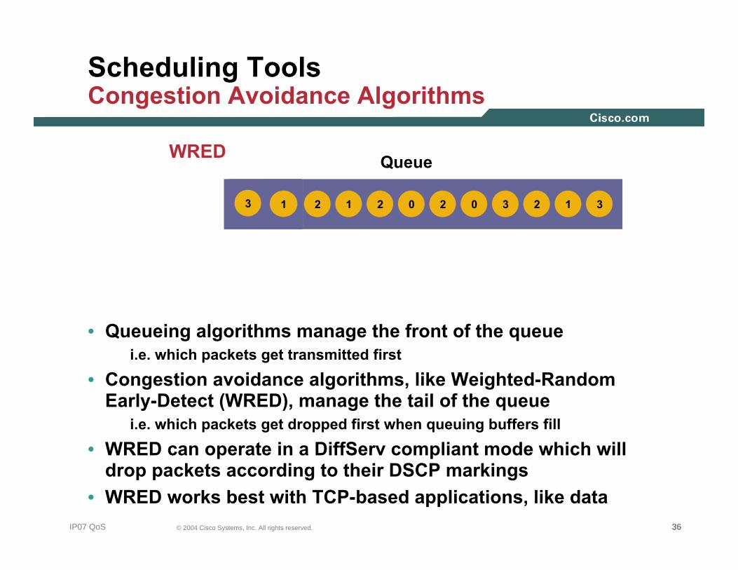
Scheduling ToolsCongestion Avoidance Algorithms
• Queueing algorithms manage the front of the queuei.e. which packets get transmitted first
• Congestion avoidance algorithms, like Weighted-Random Early-Detect (WRED), manage the tail of the queue
i.e. which packets get dropped first when queuing buffers fill
• WRED can operate in a DiffServ compliant mode which will drop packets according to their DSCP markings
• WRED works best with TCP-based applications, like data
373737© 2004 Cisco Systems, Inc. All rights reserved.IP07 QoS
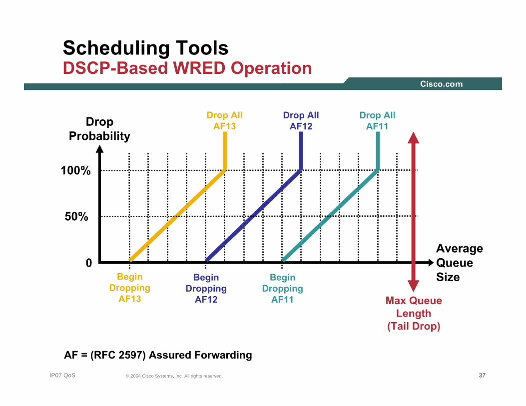
Scheduling ToolsDSCP-Based WRED Operation
AverageQueueSize
100%
0
DropProbability
BeginDropping
AF13
Drop AllAF11
AF = (RFC 2597) Assured Forwarding
Max QueueLength
(Tail Drop)
Drop AllAF12
Drop AllAF13
BeginDropping
AF12
BeginDropping
AF11
50%
383838© 2004 Cisco Systems, Inc. All rights reserved.IP07 QoS
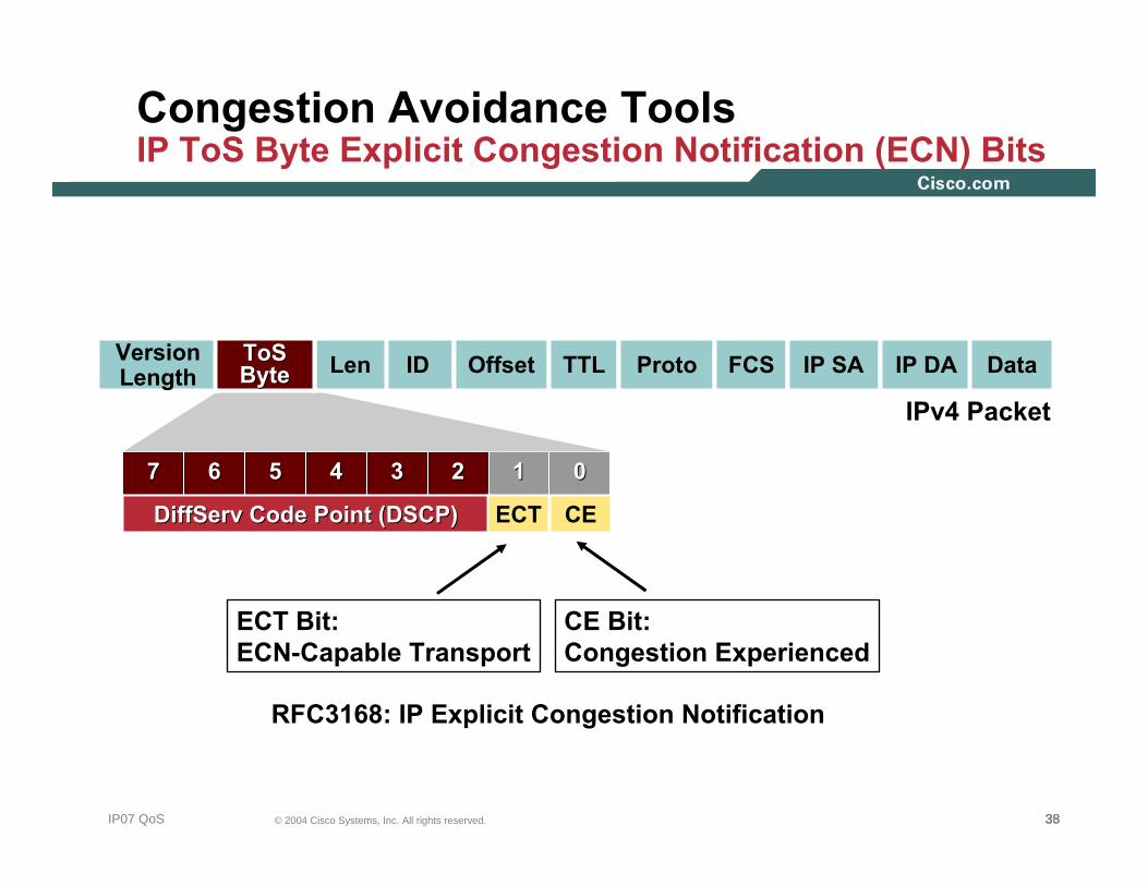
Congestion Avoidance ToolsIP ToS Byte Explicit Congestion Notification (ECN) Bits
RFC3168: IP Explicit Congestion Notification
ECT Bit:ECN-Capable Transport
CE Bit:Congestion Experienced
77 66 55 44 33 22 11 00
ID Offset TTL Proto FCS IP SA IP DA DataLenVersionLength
ToSToSByteByte
DiffServ Code Point (DSCP)DiffServ Code Point (DSCP) CE
IPv4 Packet
ECT

393939© 2004 Cisco Systems, Inc. All rights reserved.IP07 QoS
Shaping ToolsTraffic Shaping
• Policers typically drop traffic
• Shapers typically delay excess traffic, smoothing bursts and preventing unnecessary drops
• Very common on Non-Broadcast Multiple-Access (NBMA) network topologies such as Frame-Relay and ATM
With Traffic Shaping
Without Traffic ShapingLineRate
ShapedRate
Traffic Shaping Limits the Transmit Rate to a Value Lower than Line Rate
404040© 2004 Cisco Systems, Inc. All rights reserved.IP07 QoS
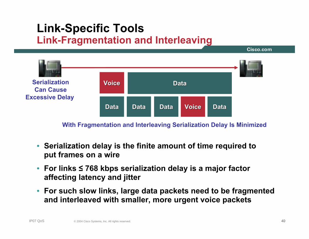
Link-Specific ToolsLink-Fragmentation and Interleaving
• Serialization delay is the finite amount of time required to put frames on a wire
• For links ≤ 768 kbps serialization delay is a major factor affecting latency and jitter
• For such slow links, large data packets need to be fragmented and interleaved with smaller, more urgent voice packets
VoiceVoice
VoiceVoice DataDataDataDataDataDataDataData
DataDataSerializationCan Cause
Excessive Delay
With Fragmentation and Interleaving Serialization Delay Is Minimized

414141© 2004 Cisco Systems, Inc. All rights reserved.IP07 QoS
Link-Specific ToolsIP RTP Header Compression
cRTP Reduces L3 VoIP BW by:~ 20% for G.711~ 60% for G.729
2-5 Bytes
RTP Header12 Bytes
RTP Header12 Bytes
VoicePayloadVoice
PayloadIP Header20 Bytes
IP Header20 Bytes
UDP Header8 Bytes
UDP Header8 Bytes

QOS DESIGN PRINCIPLES AND STRATEGIES
424242© 2004 Cisco Systems, Inc. All rights reserved.NMS-2T309681_05_2004_c2
434343© 2004 Cisco Systems, Inc. All rights reserved.IP07 QoS
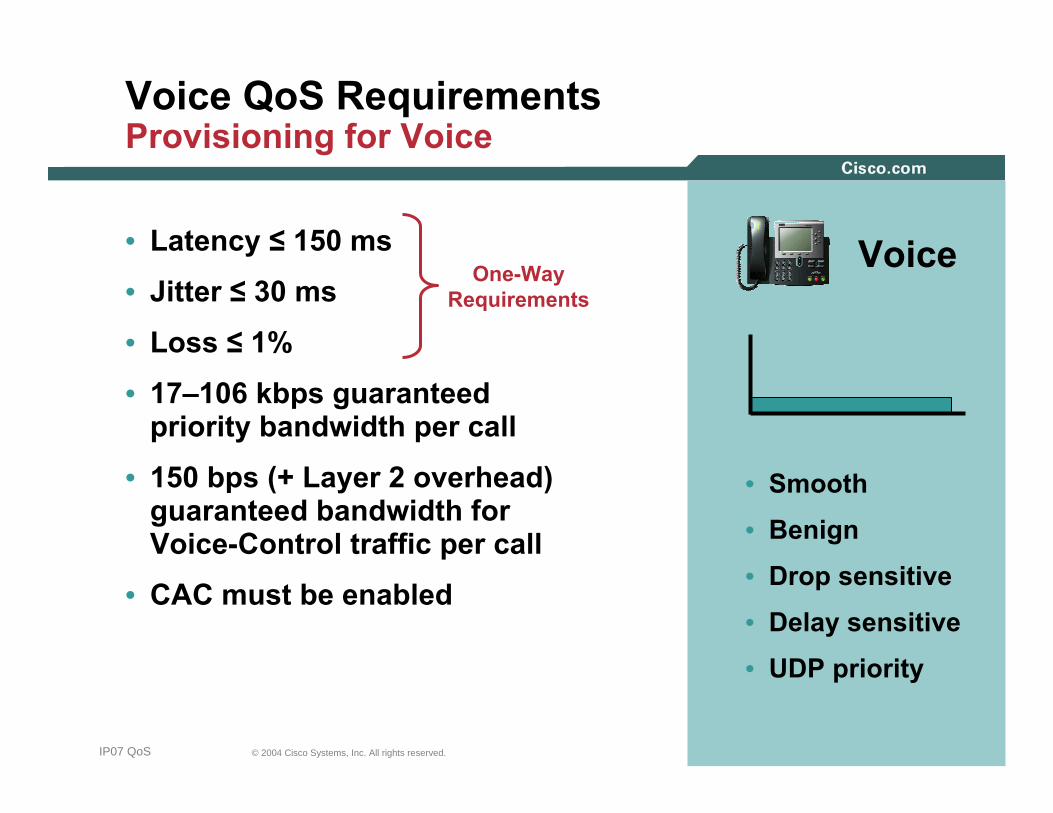
Voice QoS RequirementsProvisioning for Voice
• Latency ≤ 150 ms
• Jitter ≤ 30 ms
• Loss ≤ 1%
• 17–106 kbps guaranteed priority bandwidth per call
• 150 bps (+ Layer 2 overhead) guaranteed bandwidth for Voice-Control traffic per call
• CAC must be enabled
• Smooth
• Benign
• Drop sensitive
• Delay sensitive
• UDP priority
VoiceOne-WayRequirements
444444© 2004 Cisco Systems, Inc. All rights reserved.IP07 QoS
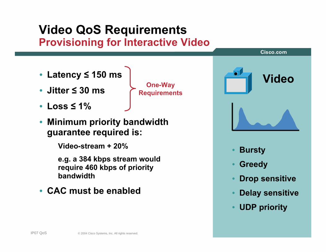
Video QoS RequirementsProvisioning for Interactive Video
• Latency ≤ 150 ms
• Jitter ≤ 30 ms
• Loss ≤ 1%
• Minimum priority bandwidth guarantee required is:
Video-stream + 20%
e.g. a 384 kbps stream would require 460 kbps of priority bandwidth
• CAC must be enabled
• Bursty
• Greedy
• Drop sensitive
• Delay sensitive
• UDP priority
VideoOne-WayRequirements
454545© 2004 Cisco Systems, Inc. All rights reserved.IP07 QoS
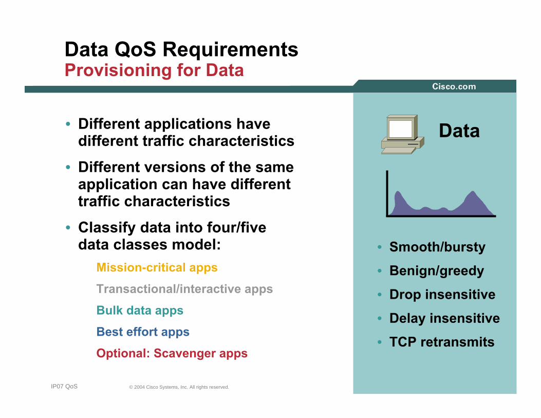
Data QoS Requirements Provisioning for Data
• Different applications have different traffic characteristics
• Different versions of the same application can have different traffic characteristics
• Classify data into four/five data classes model:
Mission-critical apps
Transactional/interactive apps
Bulk data apps
Best effort apps
Optional: Scavenger apps
Data
• Smooth/bursty
• Benign/greedy
• Drop insensitive
• Delay insensitive
• TCP retransmits
464646© 2004 Cisco Systems, Inc. All rights reserved.IP07 QoS
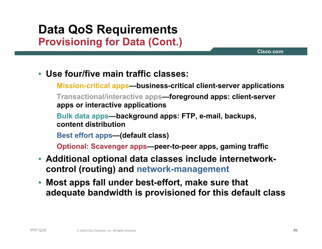
Data QoS Requirements Provisioning for Data (Cont.)
• Use four/five main traffic classes:Mission-critical apps—business-critical client-server applicationsTransactional/interactive apps—foreground apps: client-server apps or interactive applicationsBulk data apps—background apps: FTP, e-mail, backups, content distributionBest effort apps—(default class)Optional: Scavenger apps—peer-to-peer apps, gaming traffic
• Additional optional data classes include internetwork-control (routing) and network-management
• Most apps fall under best-effort, make sure that adequate bandwidth is provisioned for this default class

474747© 2004 Cisco Systems, Inc. All rights reserved.IP07 QoS
Scavenger-Class QoS DoS/Worm Mitigation StrategyWhat Is the Scavenger Class?
• The Scavenger class is an Internet 2 Draft Specification for a “less-than best effort” service
• There is an implied “good faith” commitment for the “best effort” traffic class
It is generally assumed that at least some network resourceswill be available for the default class
• Scavenger class markings can be used to distinguish out-of-profile/abnormal traffic flows from in-profile/normal flows
The Scavenger class marking is DSCP CS1 (8)
• Scavenger traffic is assigned a “less-than best effort”queuing treatment whenever congestion occurs

484848© 2004 Cisco Systems, Inc. All rights reserved.IP07 QoS
Scavenger-Class QoS DoS/Worm Mitigation StrategyFirst Order Anomaly Detection
Normal/Abnormal Threshold
• All end systems generate traffic spikes• Sustained traffic loads beyond ‘normal’ from each source
device are considered suspect and marked as scavenger (DSCP CS1)
• No dropping at campus access-edge, only remarking
Excess Traffic Is Remarked to Scavenger (DSCP CS1)
Police

494949© 2004 Cisco Systems, Inc. All rights reserved.IP07 QoS
Police
Scavenger-Class QoS DoS/Worm Mitigation StrategySecond Order Anomaly Reaction
• During ‘abnormal’ worm traffic conditions traffic, where multiple infected hosts are causing uplink congestion, suspect traffic—previously marked as Scavenger—is aggressively dropped
• Stations not generating abnormal traffic volumes continue to receive network service
Throttle Scavenger (when Congested)

505050© 2004 Cisco Systems, Inc. All rights reserved.IP07 QoS
Scavenger-Class QoS DoS/Worm Mitigation StrategyPreventing and Limiting the Pain
An Integrated Network Architecture Holistically Combines High Availability, Quality of Service and Security
Technologies to Prevent and Limit Attacks
AccessDistribution
Core
InfectedSource
SiSi
SiSi
SiSiSiSi
SystemUnder Attack
Protect the End Systems
Cisco Security AgentProtect the Switches
CEFRate Limiters
Protect the LinksQoS
Scavenger Class
Prevent the AttackCisco Guard
FirewallACLs & NBAR

515151© 2004 Cisco Systems, Inc. All rights reserved.IP07 QoS
Classification and Marking Design PrinciplesWhere and How Should Marking Be Done?
• QoS policies (in general) should always be performed in hardware, rather than software, whenever a choice exists
• Classify and mark applications as close to their sources as technically and administratively feasible
• Use DSCP markings whenever possible
• Follow standards-based DSCP PHBs to ensure interoperation and future expansion
RFC 2474 class selector code points
RFC 2597 assured forwarding classes
RFC 3246 expedited forwarding

525252© 2004 Cisco Systems, Inc. All rights reserved.IP07 QoS
Classification and MarkingQoS Baseline/AIT Marking Recommendations
ApplicationL3 Classification
DSCPPHBIPP CoS
Transactional Data 18AF212 2
Call Signaling 26 24AF31 CS3*3 3
Streaming Video 32CS44 4
Video Conferencing 34AF414 4
Voice 46EF5 5
Network Management 16CS22 2
L2
Bulk Data 10AF111 1
Scavenger 8CS11 1
Best EffortBest Effort 000000 00
RoutingRouting 4848CS6CS666 66
Mission-Critical Data 25-3 3
535353© 2004 Cisco Systems, Inc. All rights reserved.IP07 QoS
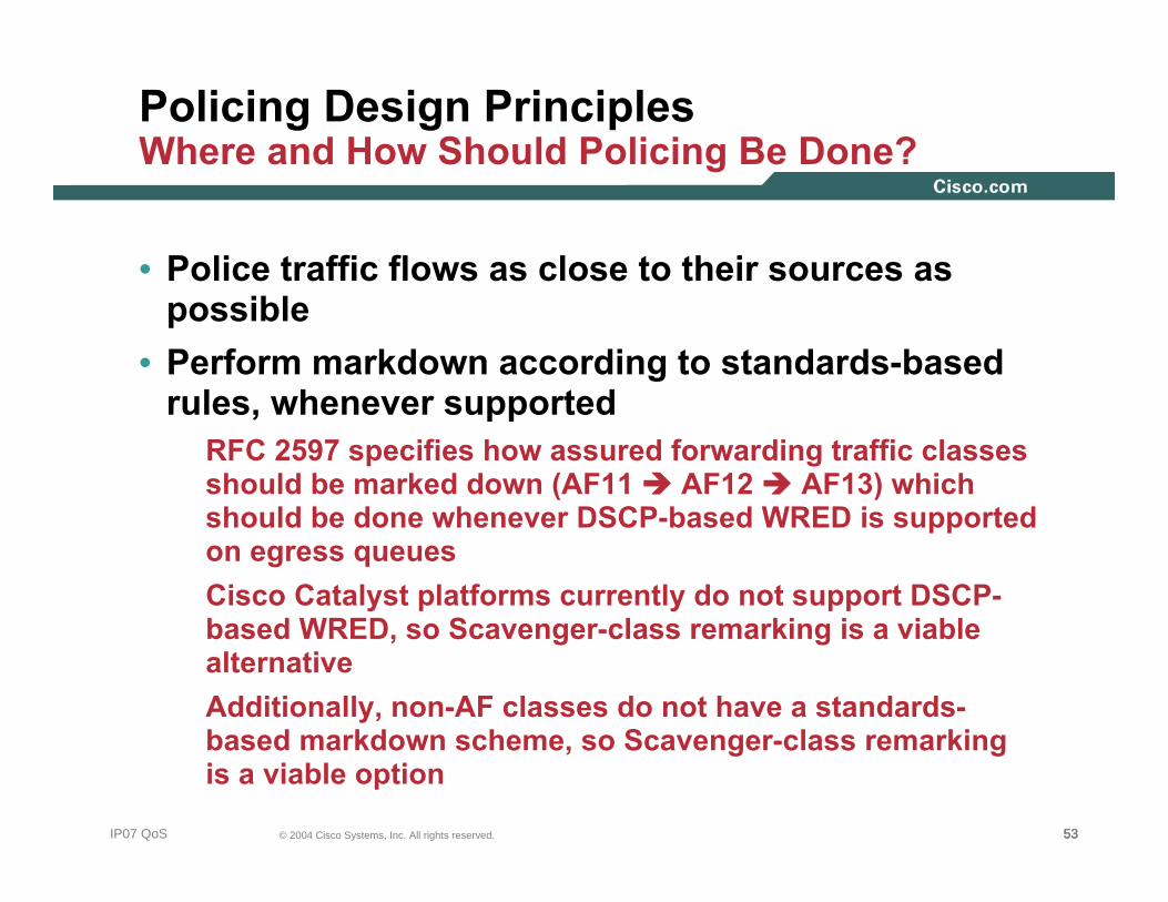
Policing Design PrinciplesWhere and How Should Policing Be Done?
• Police traffic flows as close to their sources as possible
• Perform markdown according to standards-based rules, whenever supported
RFC 2597 specifies how assured forwarding traffic classes should be marked down (AF11 AF12 AF13) which should be done whenever DSCP-based WRED is supported on egress queuesCisco Catalyst platforms currently do not support DSCP-based WRED, so Scavenger-class remarking is a viable alternativeAdditionally, non-AF classes do not have a standards-based markdown scheme, so Scavenger-class remarking is a viable option

545454© 2004 Cisco Systems, Inc. All rights reserved.IP07 QoS
DoS/Worm Mitigation Design PrinciplesHow Can QoS Tools Contain Attacks?
• Profile applications to determine what constitutes “normal”vs. “abnormal” flows (within a 95% confidence interval)
• Deploy campus access-edge policers to remark abnormal traffic to Scavenger
DSCP CS1 (8)
• Deploy a second-line of defense at the Distribution-Layer via per-user microflow policing
Cisco Catalyst 6500 Sup720 (PFC3) only
• Provision end-to-end “less-than-Best-Effort” Scavenger-class queuing policies
Campus + WAN + VPN
• Police-to-drop known worms/variants via NBAR on branch routers
555555© 2004 Cisco Systems, Inc. All rights reserved.IP07 QoS
Queuing Design PrinciplesWhere and How Should Queuing Be Done?
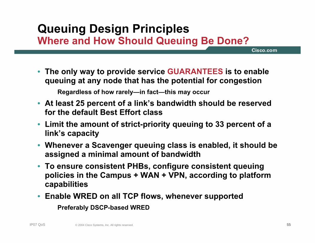
• The only way to provide service GUARANTEES is to enable queuing at any node that has the potential for congestion
Regardless of how rarely—in fact—this may occur
• At least 25 percent of a link’s bandwidth should be reserved for the default Best Effort class
• Limit the amount of strict-priority queuing to 33 percent of a link’s capacity
• Whenever a Scavenger queuing class is enabled, it should be assigned a minimal amount of bandwidth
• To ensure consistent PHBs, configure consistent queuing policies in the Campus + WAN + VPN, according to platform capabilities
• Enable WRED on all TCP flows, whenever supportedPreferably DSCP-based WRED

565656© 2004 Cisco Systems, Inc. All rights reserved.IP07 QoS
Campus Queuing DesignRealtime, Best Effort and Scavenger Queuing Rules
Real-Time ≤ 33%
Critical Data
Best Effort≥ 25%
Scavenger/Bulk ≤ 5%

575757© 2004 Cisco Systems, Inc. All rights reserved.IP07 QoS
Voice 18%
Scavenger 1%
Best Effort25%
Bulk 4%
Streaming-Video
Mission-Critical Data
Internetwork-Control
Interactive Video 15%
Call-SignalingNetwork Management
Transactional Data
Campus and WAN/VPN Queuing DesignCompatible Four-Class and Eleven-Class Queuing Models Following Realtime, Best Effort and Scavenger Queuing Rules
Real-Time ≤ 33%
Real-Time ≤ 33%
Critical DataCritical Data
Best Effort≥ 25%
Best Effort≥ 25%
Scavenger/Bulk 5%
Scavenger/Bulk 5%

58© 2004 Cisco Systems, Inc. All rights reserved.IP07 QoS
LAN/WAN/VPN QoS Design Overview

595959© 2004 Cisco Systems, Inc. All rights reserved.IP07 QoS
FastEthernetGigabitEthernetTenGigabitEthernet
Campus QoS ConsiderationsWhere Is QoS Required Within the Campus?
No Trust + Policing +QueuingConditional Trust +Policing + QueuingTrust DSCP + Queuing
Per-User MicroflowPolicing
WAN Aggregator
Catalyst 6500 Sup720
Server Farms IP Phones + PCs IP Phones + PCs
606060© 2004 Cisco Systems, Inc. All rights reserved.IP07 QoS
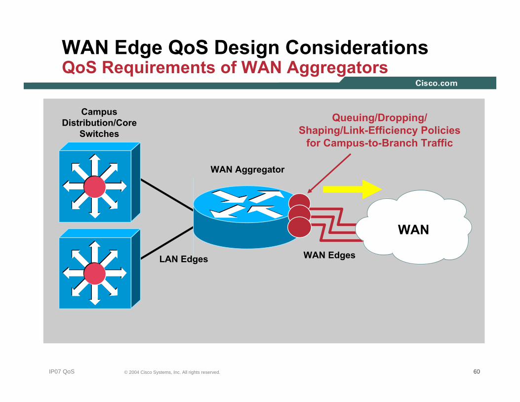
WAN Edge QoS Design ConsiderationsQoS Requirements of WAN Aggregators
WAN Aggregator
WAN Edges
CampusDistribution/Core
Switches
LAN Edges
WAN
Queuing/Dropping/Shaping/Link-Efficiency Policies
for Campus-to-Branch Traffic

616161© 2004 Cisco Systems, Inc. All rights reserved.IP07 QoS
Branch Router QoS DesignQoS Requirements for Branch Routers
Branch Router
WAN Edge
WAN
Queuing/Dropping/Shaping/Link-Efficiency Policies forBranch-to-Campus Traffic
Optional: DSCP-to-CoS Mapping Policiesfor Campus-to-Branch Traffic
LAN Edge
Classification and Marking (+ NBAR) Policies for Branch-to-Campus Traffic
BranchSwitch
626262© 2004 Cisco Systems, Inc. All rights reserved.IP07 QoS
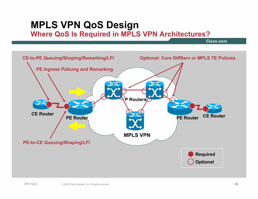
MPLS VPN QoS DesignWhere QoS Is Required in MPLS VPN Architectures?
CE Router
MPLS VPN
PE Router
P Routers
CE RouterPE Router
RequiredOptional
CE-to-PE Queuing/Shaping/Remarking/LFI
PE Ingress Policing and Remarking
PE-to-CE Queuing/Shaping/LFI
Optional: Core DiffServ or MPLS TE Policies

At-a-GlanceSummaries
636363© 2004 Cisco Systems, Inc. All rights reserved.NMS-2T309681_05_2004_c2

646464© 2004 Cisco Systems, Inc. All rights reserved.IP07 QoS
QoS Tools
DelayDelay(Latency)(Latency)
DelayDelay--VariationVariation
(Jitter)(Jitter)
PacketPacketLossLoss
QoS is the measure of transmission quality and service availability of a network (or internetworks). The transmission quality of the network is determined by the following factors: Latency, Jitter and Loss.
QoS technologies refer to the set of tools and techniques to manage network resources and are considered the key enabling technologies for the transparent convergence of voice, video and data networks. Additionally, QoS tools can play a strategic role in significantly mitigating DoS/worm attacks.
Cisco’s QoS toolset consists of the following: •Classification and Marking tools•Policing and Markdown tools•Scheduling tools•Link-specific tools•AutoQoS tools Policing and
Markdown
Classificationand Marking Scheduling
(Queuing and Selective-Dropping)
Link-SpecificMechanismsTraffic Shaping
Classification can be done at Layers 2-7:
Marking can be done at Layers 2 or Layer 3:Layer 2: 802.1Q/p CoS, MPLS EXPLayer 3: IP Precedence, DSCP and/or
IP ECN
L2 Frame L3 IP Packet
ToS/
DSCPSource
IP
Dest
IP
L4 TCP/UDP Segment
Src
Port
Dst
Port
L7 Data Payload
NBAR PDLM
•Conform: traffic is within the defined rate (green light)•Exceed: moderate bursting is allowed (yellow light)•Violate: no more traffic is allowed beyond this upper-limit (red light)
Policers meter traffic into three categories:
Layer 3 (IP ToS Byte) Marking Options:
77 66 55 44 33 22 11 00
DiffServ Code Point (DSCP) IP ECN
IP Precedence Unused
RFC 3168IP ECN BitsRFC 3168
IP ECN BitsRFC 2474
DiffServ ExtensionsRFC 2474
DiffServ Extensions
Policing tools can complement marking tools by marking metering flows and marking-down out-of-contract traffic.
Voice
Video
Data
Scheduling tools re-order and selectively-drop packets whenever congestion occurs.
Link-Specific tools are useful on slow-speed WAN/VPN links and include shaping, compression, fragmentation and interleaving.
AutoQoS features automatically configure Cisco-recommend QoS on Catalyst switches and IOS routers with just one or two commands.
Cisco recommends end-to-end marking at Layer 3 with standards-based DSCP values.
[email protected] 2004
656565© 2004 Cisco Systems, Inc. All rights reserved.IP07 QoS
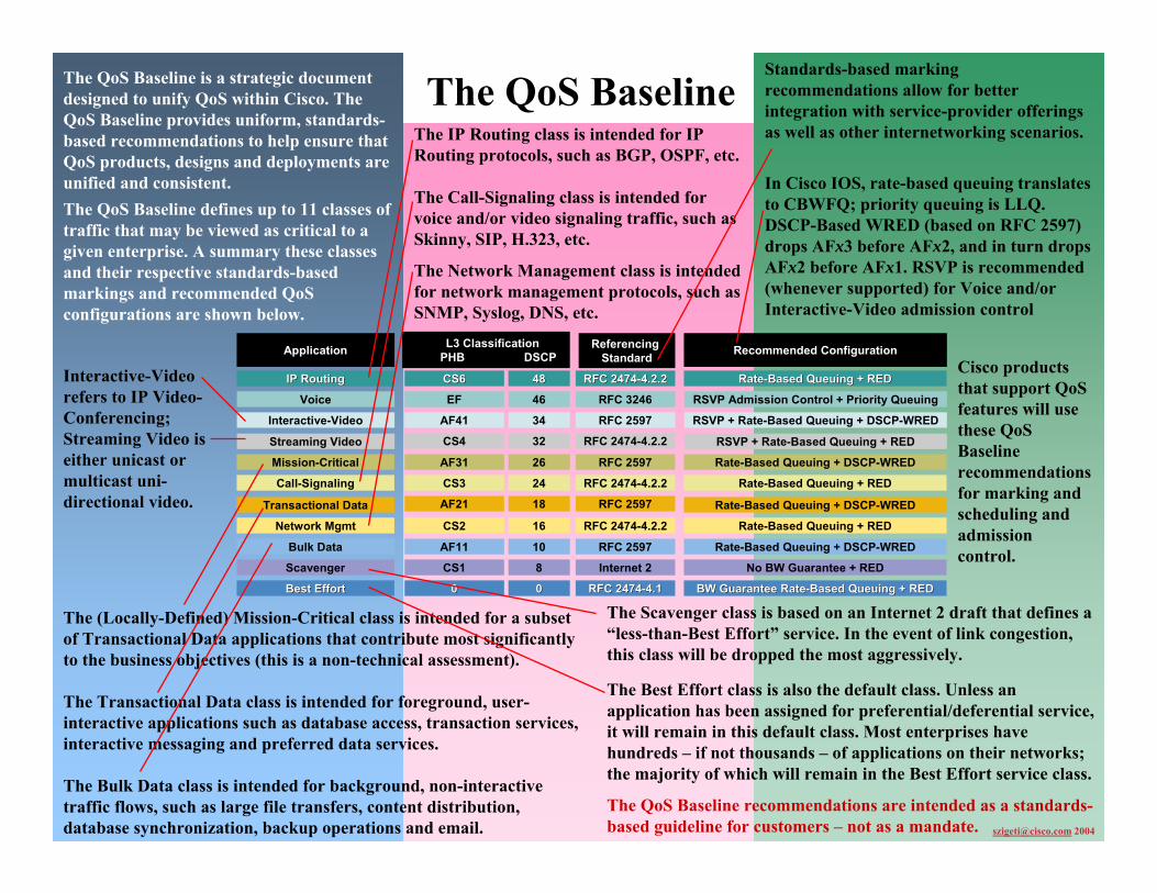
The QoS Baseline
The QoS Baseline defines up to 11 classes of traffic that may be viewed as critical to a given enterprise. A summary these classes and their respective standards-based markings and recommended QoS configurations are shown below.
Interactive-Video refers to IP Video-Conferencing; Streaming Video is either unicast or multicast uni-directional video.
The Network Management class is intended for network management protocols, such as SNMP, Syslog, DNS, etc.
[email protected] 2004
Application
Transactional Data
Call-Signaling
Streaming Video
Interactive-Video
Voice
Network Mgmt
Bulk Data
Scavenger
Best EffortBest Effort
IP RoutingIP Routing
Mission-Critical
L3 ClassificationPHB DSCP
18AF21
24CS3
32CS4
34AF41
46EF
16CS2
10AF11
8CS1
0000
4848CS6CS6
26AF31
Recommended Configuration
Rate-Based Queuing + DSCP-WRED
Rate-Based Queuing + RED
RSVP + Rate-Based Queuing + RED
RSVP + Rate-Based Queuing + DSCP-WRED
RSVP Admission Control + Priority Queuing
Rate-Based Queuing + RED
Rate-Based Queuing + DSCP-WRED
No BW Guarantee + RED
BW Guarantee RateBW Guarantee Rate--Based Queuing + REDBased Queuing + RED
RateRate--Based Queuing + REDBased Queuing + RED
Rate-Based Queuing + DSCP-WRED
RFC 2597
RFC 2474-4.2.2
RFC 2474-4.2.2
RFC 2597
RFC 3246
RFC 2474-4.2.2
RFC 2597
Internet 2
RFC 2474RFC 2474--4.14.1
RFC 2474RFC 2474--4.2.24.2.2
RFC 2597
Referencing Standard
The (Locally-Defined) Mission-Critical class is intended for a subset of Transactional Data applications that contribute most significantly to the business objectives (this is a non-technical assessment).
The Transactional Data class is intended for foreground, user-interactive applications such as database access, transaction services, interactive messaging and preferred data services.
The Bulk Data class is intended for background, non-interactive traffic flows, such as large file transfers, content distribution, database synchronization, backup operations and email.
The IP Routing class is intended for IP Routing protocols, such as BGP, OSPF, etc.
The Call-Signaling class is intended for voice and/or video signaling traffic, such as Skinny, SIP, H.323, etc.
The Scavenger class is based on an Internet 2 draft that defines a “less-than-Best Effort” service. In the event of link congestion, this class will be dropped the most aggressively.
The QoS Baseline recommendations are intended as a standards-based guideline for customers – not as a mandate.
Standards-based marking recommendations allow for better integration with service-provider offerings as well as other internetworking scenarios.
In Cisco IOS, rate-based queuing translates to CBWFQ; priority queuing is LLQ.DSCP-Based WRED (based on RFC 2597) drops AFx3 before AFx2, and in turn drops AFx2 before AFx1. RSVP is recommended (whenever supported) for Voice and/or Interactive-Video admission control
Cisco products that support QoS features will use these QoS Baseline recommendations for marking and scheduling and admission control.
The Best Effort class is also the default class. Unless an application has been assigned for preferential/deferential service, it will remain in this default class. Most enterprises have hundreds – if not thousands – of applications on their networks; the majority of which will remain in the Best Effort service class.
The QoS Baseline is a strategic document designed to unify QoS within Cisco. The QoS Baseline provides uniform, standards-based recommendations to help ensure that QoS products, designs and deployments are unified and consistent.

666666© 2004 Cisco Systems, Inc. All rights reserved.IP07 QoS
A successful QoS deployment includes three key phases:
1) Strategically defining the business objectives to be achieved via QoS.2) Analyzing the service-level requirements of the traffic classes.3) Designing and testing QoS policies
1) Strategically defining the business objectives to be achieved by QoS.
Business QoS objectives need to be defined:•Is the objective to enable VoIP only or is video also required? •If so, is video-conferencing required or streaming video? Or both?•Are there applications that are considered mission-critical? If so, what are they? •Does the organization wish to squelch certain types of traffic? If so, what are they?•Does the business want to use QoS tools to mitigate DoS/worm attacks?•How many classes of service are needed to meet the business objectives?
Because QoS introduces a system of managed unfairness, most QoS deployments inevitably entail political and organizational repercussions when implemented.
To minimize the effects of these non-technical obstacles to deployment, address these political and organizational issues as early as possible, garnishing executive endorsement whenever possible.
2) Analyze the application service-level requirements.
3) Design and test the QoS Policies.
Classify, mark and police as close to the traffic-sources as possible; following Differentiated-Services standards, such as RFC 2474, 2475, 2597, 2698 and 3246.
Provision queuing in a consistent manner (according to platform capabilities).
• No “one-size fits all”
• Smooth/Bursty
• Benign/Greedy
• TCP Retransmits/ UDP does not
Data
• Unpredicable Flows
• Drop + Delay Sensitive
• UDP Priority
• 150 ms one-way delay
• 30 ms jitter
• 1% loss
• Overprovision stream by 20% to account for headers + bursts
Video
• Predicable Flows
• Drop + Delay Sensitive
• UDP Priority
• 150 ms one-way delay
• 30 ms jitter
• 1% loss
• 17 kbps-106 kbps VoIP + Call-Signaling
VoiceApplication
Transactional Data
Call-Signaling
Streaming Video
Interactive-Video
Voice
Network Mgmt
Bulk Data
Scavenger
Best EffortBest Effort
RoutingRouting
Mission-Critical
L3 ClassificationPHB DSCP
18AF21
24CS3
32CS4
34AF41
46EF
16CS2
10AF11
8CS1
0000
4848CS6CS6
26AF31
Voice
Scavenger
Best Effort
Bulk
Streaming-Video
Mission-Critical
Routing
Interactive-Video
Call-SignalingNet Mgmt
Transactional
Real-time ≤ 33%
Critical Data
Best Effort≥ 25%
Thoroughly test QoS policies prior to production-network deployment.
QoS Best-Practices
[email protected] 2004
676767© 2004 Cisco Systems, Inc. All rights reserved.IP07 QoS
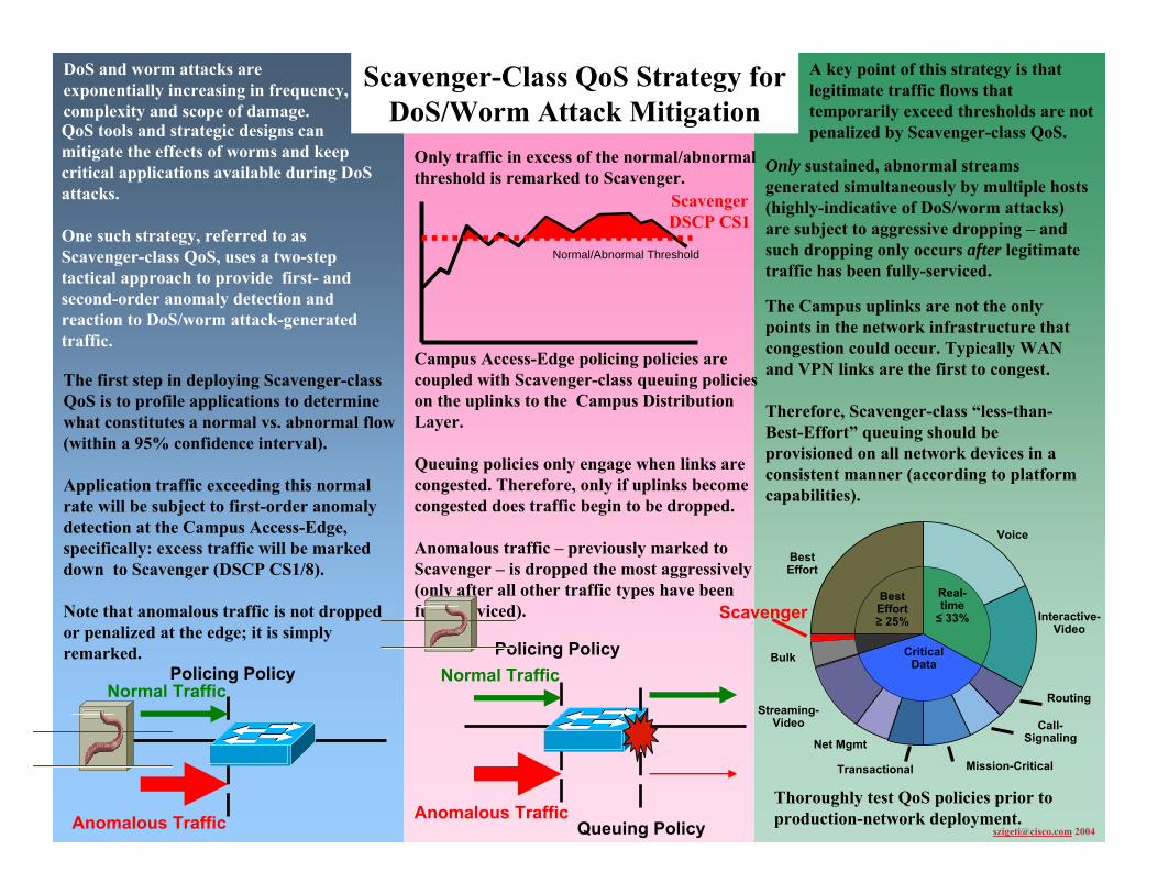
DoS and worm attacks are exponentially increasing in frequency, complexity and scope of damage.
The first step in deploying Scavenger-class QoS is to profile applications to determine what constitutes a normal vs. abnormal flow (within a 95% confidence interval).
Application traffic exceeding this normal rate will be subject to first-order anomaly detection at the Campus Access-Edge, specifically: excess traffic will be marked down to Scavenger (DSCP CS1/8).
Note that anomalous traffic is not dropped or penalized at the edge; it is simply remarked.
Only traffic in excess of the normal/abnormal threshold is remarked to Scavenger.
The Campus uplinks are not the only points in the network infrastructure that congestion could occur. Typically WAN and VPN links are the first to congest.
Therefore, Scavenger-class “less-than-Best-Effort” queuing should be provisioned on all network devices in a consistent manner (according to platform capabilities).
Voice
Scavenger
Best Effort
Bulk
Streaming-Video
Mission-Critical
Routing
Interactive-Video
Call-SignalingNet Mgmt
Transactional
Real-time ≤ 33%
Critical Data
Best Effort≥ 25%
Thoroughly test QoS policies prior to production-network deployment.
Policing Policy
Anomalous Traffic
Normal Traffic
Campus Access-Edge policing policies are coupled with Scavenger-class queuing policies on the uplinks to the Campus Distribution Layer.
Queuing policies only engage when links are congested. Therefore, only if uplinks become congested does traffic begin to be dropped.
Anomalous traffic – previously marked to Scavenger – is dropped the most aggressively (only after all other traffic types have been fully-serviced).
Policing Policy
Queuing Policy
Normal Traffic
Anomalous Traffic
Normal/Abnormal Threshold
ScavengerDSCP CS1
A key point of this strategy is that legitimate traffic flows that temporarily exceed thresholds are not penalized by Scavenger-class QoS.
Only sustained, abnormal streams generated simultaneously by multiple hosts (highly-indicative of DoS/worm attacks) are subject to aggressive dropping – and such dropping only occurs after legitimate traffic has been fully-serviced.
QoS tools and strategic designs can mitigate the effects of worms and keep critical applications available during DoS attacks.
One such strategy, referred to as Scavenger-class QoS, uses a two-step tactical approach to provide first- and second-order anomaly detection and reaction to DoS/worm attack-generated traffic.
Scavenger-Class QoS Strategy for DoS/Worm Attack Mitigation
[email protected] 2004
686868© 2004 Cisco Systems, Inc. All rights reserved.IP07 QoS
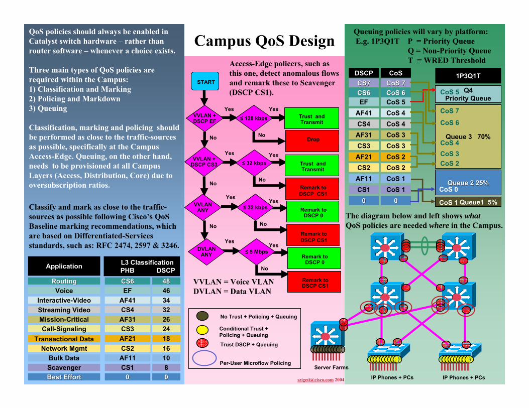
QoS policies should always be enabled in Catalyst switch hardware – rather than router software – whenever a choice exists.
Three main types of QoS policies are required within the Campus:1) Classification and Marking2) Policing and Markdown3) Queuing
Classification, marking and policing should be performed as close to the traffic-sources as possible, specifically at the Campus Access-Edge. Queuing, on the other hand, needs to be provisioned at all Campus Layers (Access, Distribution, Core) due to oversubscription ratios.
Classify and mark as close to the traffic-sources as possible following Cisco’s QoS Baseline marking recommendations, which are based on Differentiated-Services standards, such as: RFC 2474, 2597 & 3246.
Access-Edge policers, such as this one, detect anomalous flows and remark these to Scavenger (DSCP CS1).
Application
Transactional DataCall-Signaling
Streaming VideoInteractive-Video
Voice
Network MgmtBulk DataScavengerBest EffortBest Effort
RoutingRouting
Mission-Critical
L3 ClassificationPHB DSCP
18AF2124CS3
32CS434AF4146EF
16CS210AF118CS10000
4848CS6CS6
26AF31
Campus QoS Design
START
VVLAN +DSCP EF ≤ 128 kbps
YesYes
No
VVLANANY ≤ 32 kbps
YesYes
No
VVLAN +DSCP CS3 ≤ 32 kbps
YesYes
No
DVLANANY ≤ 5 Mbps
YesYes
No
Trust and Transmit
Drop
Trust and Transmit
Remark to DSCP CS1
Remark toDSCP 0
Remark to DSCP CS1
Remark to DSCP 0
Remark to DSCP CS1
No
No
No
Trust DSCP + Queuing
Conditional Trust +Policing + Queuing
No Trust + Policing + Queuing
Per-User Microflow PolicingServer Farms
IP Phones + PCs IP Phones + PCs
Q4Priority Queue
1P3Q1T
Queue1 5%CoS 1
AF21CS3
CS4AF41
EF
CS2AF11CS1
00
CS6CS6
AF31
DSCPCS7CS7
CoS 2CoS 3
CoS 4CoS 4CoS 5
CoS 2CoS 1CoS 1
00
CoS 6CoS 6
CoS 3
CoS
Queue 3 70%
CoS 7CoS 7CoS 5
CoS 3CoS 2
CoS 4
CoS 6
CoS 7
Queue 2 25%Queue 2 25%CoS 0
The diagram below and left shows whatQoS policies are needed where in the Campus.
Queuing policies will vary by platform:E.g. 1P3Q1T P = Priority Queue
Q = Non-Priority QueueT = WRED Threshold
VVLAN = Voice VLANDVLAN = Data VLAN
[email protected] 2004

696969© 2004 Cisco Systems, Inc. All rights reserved.IP07 QoS
WAN QoS DesignIn an enterprise network infrastructure, bandwidth is scarcest – and thus most expensive – over the WAN. Therefore, the business case for efficient bandwidth optimization via QoS technologies is strongest over the WAN.
Queuing Models for 5/8/11 Classes of Service are shown below:
Link-Specific Design Recommendations:
WAG
Branch
ATM Link
ATMCloud
WAG ATM-to-FR SIW Link
ATM Cloud
FR Cloud
Branch
5 Class Model
Scavenger
Critical Data
Call Signaling
Best EffortBest Effort
Realtime
8 Class Model
Critical Data
Video
Call Signaling
Best EffortBest Effort
Voice
Bulk Data
Network ControlNetwork Control
Scavenger
QoS BaselineModel
Network Mgmt
Call Signaling
Streaming Video
Transactional
Interactive-Video
Voice
Best EffortBest Effort
IP RoutingIP Routing
Mission-Critica
Scavenger
Bulk Data
Time
Voice 18%
Best Effort25%
Bulk 4%
Streaming Video 10%
Mission-Critical Data 10%
Call Signaling 5%
Interactive-Video 15%
Routing 3%Network Mgmt 2%
Transactional Data 7%
Scavenger 1%
WAN links can be categorized into three main speed groups:• Slow-Speed (≤ 768 kbps)• Medium-Speed (> 768 kbps & ≤ T1/E1)• High-Speed (≥ T1/E1)
The number of WAN classes of traffic is determined by the business objectives and may be expanded over time.
WAN QoS tools: Link Fragmentation and Interleaving
WAG Leased-Line (MLP) Link
Branch
• Use MLP LFI and cRTP on Slow-Speed links
Branch
WAG Frame Relay Link
Frame RelayCloud
• Use Frame-Relay traffic shaping• Set CIR to 95% of guaranteed rate• Set Committed Burst to CIR/100• Set Excess Burst to 0
• Use FRF.12 and and cRTP on Slow-Speed links
• Use MLP LFI (via MLPoATM) and cRTP on Slow-Speed links• Set the ATM PVC Tx-Ring to 3 for Slow-Speed links
• Use MLP LFI (via MLPoATM and MLPoFR) for Slow-Speed Links• Optimize fragment sizes to minimize ATM cell-padding
cRTP saves:~ 20% for G.711~ 60% for G.729
WAN QoS tools: RTP Header Compression (cRTP)
cRTP Header2-5 Bytes
IP Header UDP Hdr RTP Hdr VoIP20 Bytes 8 Bytes 12 Bytes
[email protected] 2004
LFI tools (MLP LFI or FRF.12) fragment large data packets and interleave these with high-priority VoIP.
VoIP Data
Data Data Data VoIP Data
WAN QoS policies need to be configured on the WAN edges of WAN Aggregator (WAG) routers and Branch routers. WAN edge QoS policies include queuing, shaping, selective-dropping and link-specific policies.

707070© 2004 Cisco Systems, Inc. All rights reserved.IP07 QoS
Branch QoS DesignBranch routers are connected to central sites via private-WAN or VPN links which often prove to be the bottlenecks for traffic flows. QoS policies at these bottlenecks align expensive WAN/VPN bandwidth utilization with business objectives.
QoS designs for Branch routers are – for the most part – identical to WAN Aggregator QoS designs. However, Branch routers require three unique QoS considerations:1) Unidirectional applications2) Ingress classification requirements3) NBAR policies for worm policing
Each of these Branch router QoS design considerations will be overviewed.
An example 10-class QoS Baseline Branch Router WAN Edge Queuing Model:
3) NBAR for Known Worm Policing
Voice 18%
Best Effort25%
Bulk 4%
Mission-Critical Data 15%
Call Signaling
5%
Interactive Video 15%
Routing 3%Network Mgmt 2%
Transactional Data 12%
Scavenger 1%
L2 Frame L3 IP Packet L4 Segment L7 Data Payload
Worm
1) Unidirectional Applications Some applications (like Streaming Video) usually only traverse the WAN/VPN in the Campus-to-Branch direction and therefore do not require provisioning in the Branch-to-Campus direction on the Branch router’s WAN edge.
Bandwidth for such unidirectional application classes can be reassigned to other critical classes, as shown in the following diagram. Notice that no Streaming Video class is provisioned and the bandwidth allocated to it (on the Campus side of the WAN link) is reallocated to the Mission-Critical and Transactional Data classes.
2) Ingress Classification Branch-to-Campus traffic may not be correctly marked on the Branch Access Layer switch.
These switches – which are usually lower-end switches – may or may not have the capabilities to classify and mark application traffic. Therefore, classification and marking may need to be performed on the Branch router’s LAN edge (in the ingress direction).
Furthermore, Branch routers offer the ability to use NBAR to classify and mark traffic flows that require stateful packet inspection.
The Branch router’s ingress LAN edge is a strategic place to use NBAR to identify & drop worms, such as CodeRed, NIMDA, SQL Slammer, MS-Blaster and Sasser.
1. The enabling code
2. The propagation mechanism
3. The payload
Where is QoS required on Branch routers?LLQ/CBWFQ/WRED/
Shaping/LFI/cRTP Policies for Branch-to-Campus Traffic
Optional: DSCP-to-CoS Mapping Policies for Campus-to-Branch Traffic
Classification & Marking + NBAR Worm Policing
Policies for Branch-to-Campus Traffic
Branch Router
WAN/VPN
BranchSwitch
WAN Edge LAN Edge
DVLAN
VVLAN
NBAR extensions allow for custom Packet Data Language Modules (PDLMs) to be defined for future worms.
Worms are nothing new, but they have increased exponentially in frequency, complexity and scope of damage in recent years.
[email protected] 2004
717171© 2004 Cisco Systems, Inc. All rights reserved.IP07 QoS
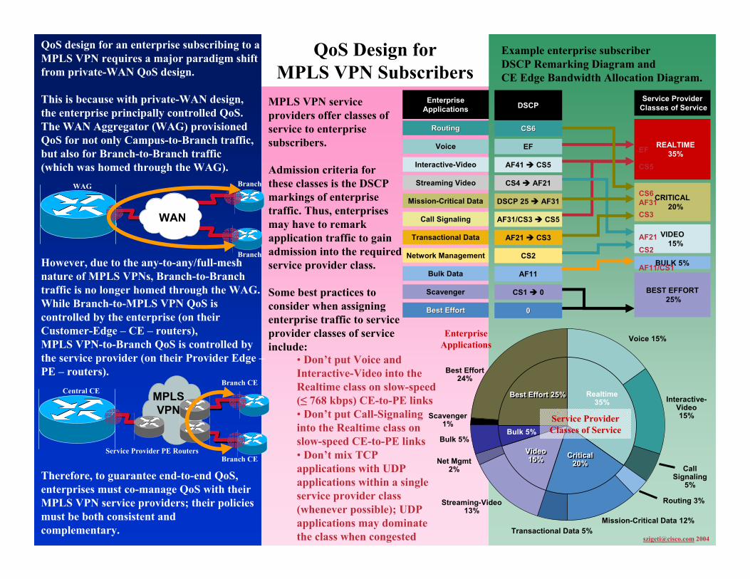
QoS Design for MPLS VPN Subscribers
QoS design for an enterprise subscribing to a MPLS VPN requires a major paradigm shift from private-WAN QoS design.
This is because with private-WAN design, the enterprise principally controlled QoS. The WAN Aggregator (WAG) provisioned QoS for not only Campus-to-Branch traffic, but also for Branch-to-Branch traffic (which was homed through the WAG).
However, due to the any-to-any/full-mesh nature of MPLS VPNs, Branch-to-Branch traffic is no longer homed through the WAG. While Branch-to-MPLS VPN QoS is controlled by the enterprise (on their Customer-Edge – CE – routers), MPLS VPN-to-Branch QoS is controlled by the service provider (on their Provider Edge –PE – routers).
Example enterprise subscriber DSCP Remarking Diagram and CE Edge Bandwidth Allocation Diagram.
Therefore, to guarantee end-to-end QoS, enterprises must co-manage QoS with their MPLS VPN service providers; their policies must be both consistent and complementary.
MPLS VPN service providers offer classes of service to enterprise subscribers.
Admission criteria for these classes is the DSCP markings of enterprise traffic. Thus, enterprises may have to remark application traffic to gain admission into the required service provider class.
Some best practices to consider when assigning enterprise traffic to serviceprovider classes of service include:
Branch
WAG Branch
WAN
Branch CE
Central CEBranch CE
MPLSVPN
Service Provider PE Routers
REALTIME35%
AF21 CS3
AF31/CS3 CS5
CS4 AF21
AF41 CS5
EF
CS2
AF11
CS1 0
00
CS6CS6
Network Management
Call Signaling
Streaming Video
Transactional Data
Interactive-Video
Voice
EnterpriseApplications
Bulk Data
Scavenger
Best EffortBest Effort
RoutingRouting
Mission-Critical Data DSCP 25 AF31
DSCP
CRITICAL20%
VIDEO15%
Service ProviderClasses of Service
EF
CS5
CS6AF31CS3
AF21CS2
BEST EFFORT25%
BULK 5%AF11/CS1
• Don’t put Voice and Interactive-Video into the Realtime class on slow-speed (≤ 768 kbps) CE-to-PE links• Don’t put Call-Signaling into the Realtime class on slow-speed CE-to-PE links• Don’t mix TCP applications with UDP applications within a single service provider class (whenever possible); UDP applications may dominate the class when congested
Scavenger 1%
Net Mgmt2%
Voice 15%
Best Effort24%
Bulk 5%
Streaming-Video 13%
Mission-Critical Data 12%
Call Signaling
5%
Interactive-Video 15%
Routing 3%
Transactional Data 5%
Realtime35%
Best Effort 25%Best Effort 25%
Video15%
Video15%
Bulk 5%
Critical 20%
Critical 20%
Service ProviderClasses of Service
Enterprise Applications
[email protected] 2004

727272© 2004 Cisco Systems, Inc. All rights reserved.IP07 QoS
QoS Design for MPLS VPN Service Providers
In order to support enterprise-subscriber voice, video and data networks, service providers must include QoS provisioning within their MPLS VPN service offerings.
This is due to the any-to-any/full-mesh nature of MPLS VPNs, where enterprise subscribers depend on their service providers to provision Provider-Edge (PE) to Customer-Edge (CE) QoS policies consistent with their CE-to-PE policies.
In addition to these PE-to-CE policies, service providers will likely implement ingress policers on their PEs to identify whether traffic flows are in- or out-of-contract. Optionally, service providers may also provision QoS policies within their core networks, using Differentiated Services and/or MPLS Traffic Engineering (TE).
RFC 3270 presents three modes of MPLS/DiffServ marking for service providers:1) Uniform Mode: SP can remark customer DSCP values2) Pipe Mode: SP does not remark customer DSCP values (SP uses independent MPLS EXP markings); final PE-to-CE policies are based on service provider’s markings3) Short Pipe Mode (shown below): SP does not remark customer DSCP values (SP uses independent MPLS EXP markings); final PE-to-CE policies are based on customer’smarkings
[email protected] 2004
CE Router
MPLS VPN
PE Router
P Routers
CE RouterPE Router
PE Ingress Policing and Re-Marking
PE-to-CE LLQ/CBWFQ/WRED/
Shaping/LFI
Optional: Core DiffServ or MPLS TE Policies
RequiredOptional
In order to guarantee end-to-end QoS, enterprises must co-manage QoS with their MPLS VPN service providers; their policies must be both consistent and complementary.
CE Router
MPLS VPN
PE Router
Provider (P)Routers
CE RouterPE Router
3) Assume a policer remarks out-of-contract traffic’s top-most MPLS label to
MPLS EXP 0
DSCP AF31DSCP AF31
1) Packet initiallymarked to
DSCP AF31
MPLS EXP 4MPLS EXP 4
MPLS EXP 4
DSCP AF31
2) MPLS EXP valuesare set independently
from DSCP values
MPLS EXP 4MPLS EXP 4
MPLS EXP 0
DSCP AF31
4) Topmost label is marked down
by a policer
5) Topmost label Is popped and
MPLS EXP value is copied to
underlying label
7) Original customer-marked DSCP
values are preserved
Shaded Area represents Service Provider DiffServ Domain
6) PE-to-CE policiesare based on
Customer-Markings
Direction of Packet Flow
Unshaded Areasrepresent Customer
DiffServ Domain
MPLS EXP 0MPLS EXP 0
DSCP AF31
Service providers can guarantee service levels within their core by:1) Aggregate Bandwidth Overprovisioning: adding redundant links when utilization hits 50% (simple to implement, but expensive and inefficient)2) Core DiffServ policies: simplified DiffServ policies for core links3) MPLS TE: TE provides granular policy-based control over traffic flows within the core
Service providers can mark at Layer 2 (MPLS EXP) or at Layer 3 (DSCP).
737373© 2004 Cisco Systems, Inc. All rights reserved.IP07 QoS
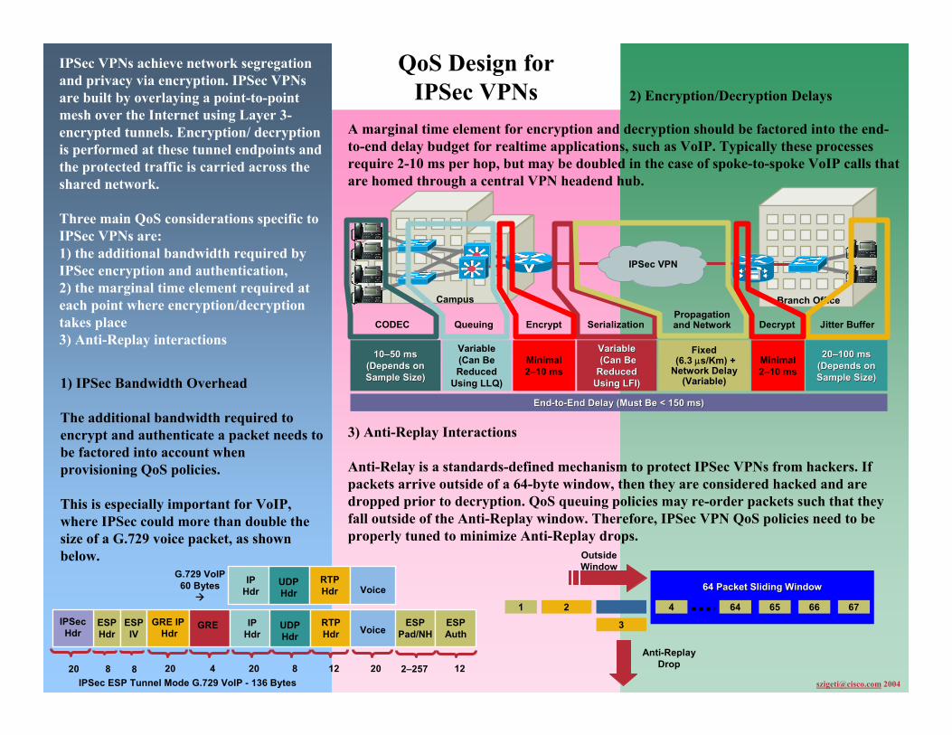
QoS Design for IPSec VPNs
IPSec VPNs achieve network segregation and privacy via encryption. IPSec VPNs are built by overlaying a point-to-point mesh over the Internet using Layer 3-encrypted tunnels. Encryption/ decryption is performed at these tunnel endpoints and the protected traffic is carried across the shared network.
Three main QoS considerations specific to IPSec VPNs are: 1) the additional bandwidth required by IPSec encryption and authentication,2) the marginal time element required at each point where encryption/decryption takes place3) Anti-Replay interactions
[email protected] 2004
2) Encryption/Decryption Delays
1) IPSec Bandwidth Overhead
The additional bandwidth required to encrypt and authenticate a packet needs to be factored into account when provisioning QoS policies.
This is especially important for VoIP, where IPSec could more than double the size of a G.729 voice packet, as shown below.
G.729 VoIP60 Bytes
IPSec ESP Tunnel Mode G.729 VoIP - 136 Bytes
ESPPad/NH
ESPAuth
122–257
IPHdr
RTPHdr
ESPHdr
ESPIV
8820
IPSecHdr
Voice
GRE IPHdr
GRE IPHdr
RTPHdr
12820420 20
Voice
Campus Branch Office
EndEnd--toto--End Delay (Must Be End Delay (Must Be << 150 ms)150 ms)
1010––50 ms50 ms(Depends on(Depends onSample Size)Sample Size)
CODEC
Variable(Can BeReduced
Using LLQ)
Queuing
VariableVariable(Can Be(Can Be
ReducedReducedUsing LFI)Using LFI)
Serialization
Fixed(6.3 µs/Km) +
Network Delay(Variable)
Propagationand Network
2020––100 ms100 ms(Depends on(Depends onSample Size)Sample Size)
Jitter Buffer
Minimal2–10 ms
Encrypt
Minimal2–10 ms
Decrypt
IPSec VPN
64 Packet Sliding Window64 Packet Sliding Window64 Packet Sliding Window
1 2 4 64 65 66 67
3
Anti-ReplayDrop
OutsideWindow
A marginal time element for encryption and decryption should be factored into the end-to-end delay budget for realtime applications, such as VoIP. Typically these processes require 2-10 ms per hop, but may be doubled in the case of spoke-to-spoke VoIP calls that are homed through a central VPN headend hub.
3) Anti-Replay Interactions
Anti-Relay is a standards-defined mechanism to protect IPSec VPNs from hackers. If packets arrive outside of a 64-byte window, then they are considered hacked and are dropped prior to decryption. QoS queuing policies may re-order packets such that they fall outside of the Anti-Replay window. Therefore, IPSec VPN QoS policies need to be properly tuned to minimize Anti-Replay drops.
UDPHdr
UDPHdr
747474© 2004 Cisco Systems, Inc. All rights reserved.IP07 QoS
Q & A
747474© 2004 Cisco Systems, Inc. All rights reserved.NMS-2T309681_05_2004_c2
REFERENCES
757575© 2004 Cisco Systems, Inc. All rights reserved.NMS-2T309681_05_2004_c2
767676© 2004 Cisco Systems, Inc. All rights reserved.IP07 QoS
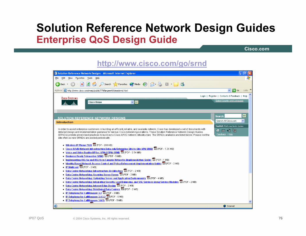
Solution Reference Network Design GuidesEnterprise QoS Design Guide
http://www.cisco.com/go/srnd

777777© 2004 Cisco Systems, Inc. All rights reserved.IP07 QoS
Solution Reference Network Design Guides Site-to-Site V3PN Design Guide
http://www.cisco.com/go/srnd
787878© 2004 Cisco Systems, Inc. All rights reserved.IP07 QoS
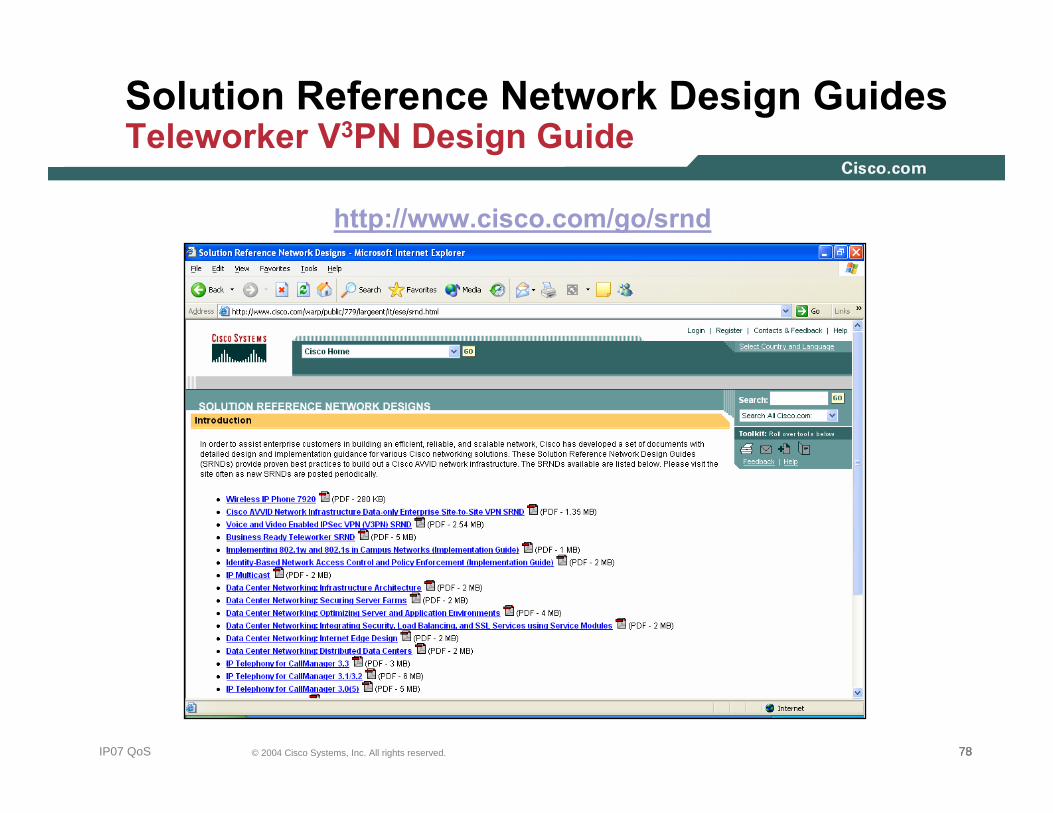
Solution Reference Network Design Guides Teleworker V3PN Design Guide
http://www.cisco.com/go/srnd
797979© 2004 Cisco Systems, Inc. All rights reserved.IP07 QoS
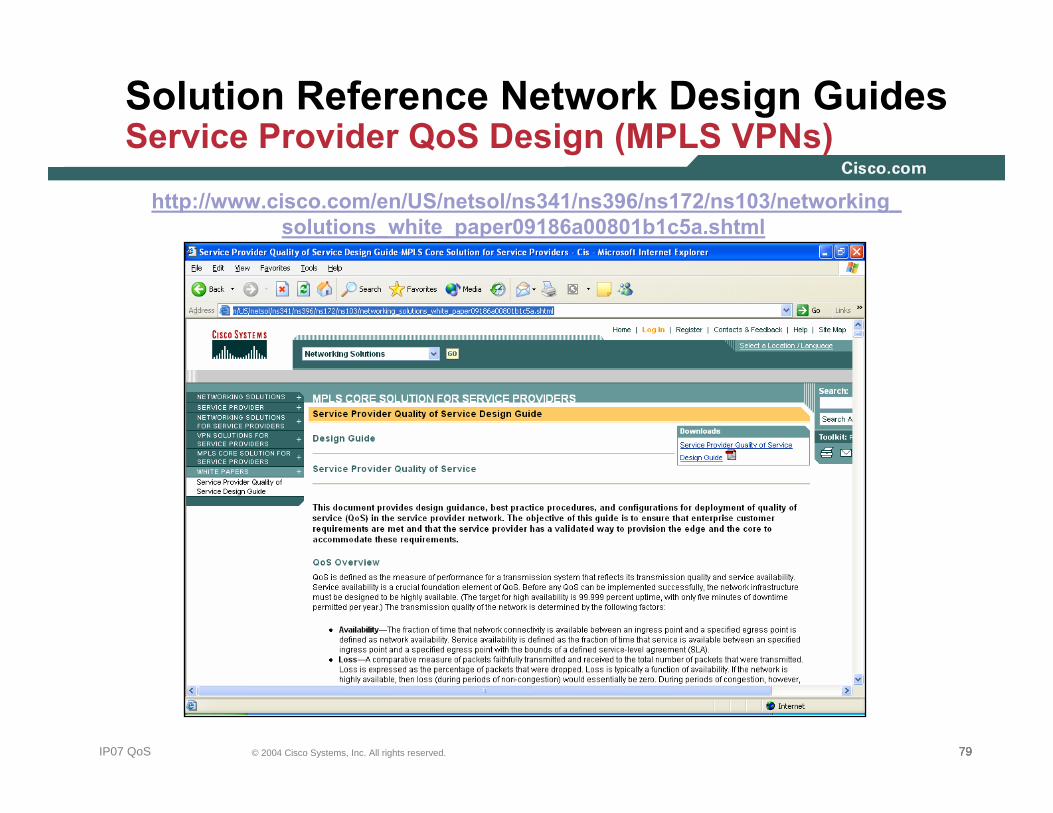
Solution Reference Network Design GuidesService Provider QoS Design (MPLS VPNs)
http://www.cisco.com/en/US/netsol/ns341/ns396/ns172/ns103/networking_solutions_white_paper09186a00801b1c5a.shtml
808080© 2004 Cisco Systems, Inc. All rights reserved.IP07 QoS
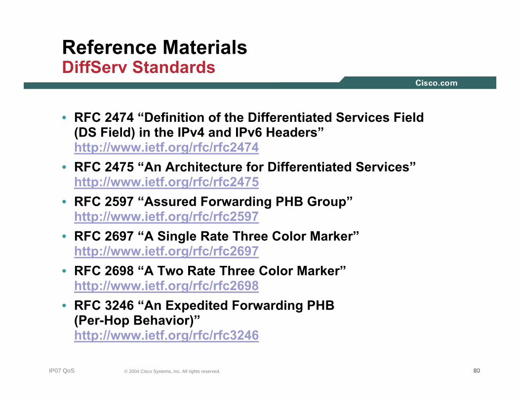
Reference MaterialsDiffServ Standards
• RFC 2474 “Definition of the Differentiated Services Field (DS Field) in the IPv4 and IPv6 Headers”http://www.ietf.org/rfc/rfc2474
• RFC 2475 “An Architecture for Differentiated Services”http://www.ietf.org/rfc/rfc2475
• RFC 2597 “Assured Forwarding PHB Group”http://www.ietf.org/rfc/rfc2597
• RFC 2697 “A Single Rate Three Color Marker”http://www.ietf.org/rfc/rfc2697
• RFC 2698 “A Two Rate Three Color Marker”http://www.ietf.org/rfc/rfc2698
• RFC 3246 “An Expedited Forwarding PHB (Per-Hop Behavior)”http://www.ietf.org/rfc/rfc3246

818181© 2004 Cisco Systems, Inc. All rights reserved.IP07 QoS
Reference MaterialsCampus QoS Documentation
• Cisco Catalyst 2950 QoS http://www.cisco.com/univercd/cc/td/doc/product/lan/cat2950/12120ea2/2950scg/swqos.htm
• Cisco Catalyst 2970 QoS http://www.cisco.com/univercd/cc/td/doc/product/lan/cat2970/12220se/2970scg/swqos.htm
• Cisco Catalyst 3550 QoS http://www.cisco.com/univercd/cc/td/doc/product/lan/c3550/12120ea2/3550scg/swqos.htm
• Cisco Catalyst 3750 QoS http://www.cisco.com/univercd/cc/td/doc/product/lan/cat3750/12220se/3750scg/swqos.htm
• Cisco Catalyst 4500 (Cisco IOS) QoS http://www.cisco.com/univercd/cc/td/doc/product/lan/cat4000/12_2_18/config/qos.htm
• Cisco Catalyst 6500 (Cisco Catalyst OS) http://www.cisco.com/univercd/cc/td/doc/product/lan/cat6000/sw_8_3/confg_gd/qos.htm
• Cisco Catalyst 6500 (Cisco IOS) http://www.cisco.com/univercd/cc/td/doc/product/lan/cat6000/122sx/swcg/qos.htm
828282© 2004 Cisco Systems, Inc. All rights reserved.IP07 QoS
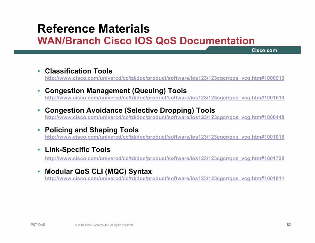
Reference MaterialsWAN/Branch Cisco IOS QoS Documentation
• Classification Tools http://www.cisco.com/univercd/cc/td/doc/product/software/ios123/123cgcr/qos_vcg.htm#1000913
• Congestion Management (Queuing) Tools http://www.cisco.com/univercd/cc/td/doc/product/software/ios123/123cgcr/qos_vcg.htm#1001619
• Congestion Avoidance (Selective Dropping) Tools http://www.cisco.com/univercd/cc/td/doc/product/software/ios123/123cgcr/qos_vcg.htm#1000448
• Policing and Shaping Tools http://www.cisco.com/univercd/cc/td/doc/product/software/ios123/123cgcr/qos_vcg.htm#1001018
• Link-Specific Tools http://www.cisco.com/univercd/cc/td/doc/product/software/ios123/123cgcr/qos_vcg.htm#1001728
• Modular QoS CLI (MQC) Syntax http://www.cisco.com/univercd/cc/td/doc/product/software/ios123/123cgcr/qos_vcg.htm#1001811

838383© 2004 Cisco Systems, Inc. All rights reserved.IP07 QoS
Reference MaterialsNBAR vs. Worms (SAFE White Papers)
• Code Red http://www.cisco.com/en/US/products/hw/routers/ps359/ products_tech_note09186a00800fc176.shtml
• Nimda http://www.cisco.com/en/US/products/sw/iosswrel/ps1835/ products_tech_note09186a0080110d17.shtml
• SQL Slammer http://www.cisco.com/en/US/netsol/ns340/ns394/ns171/ns128/ networking_solutions_white_paper09186a00801cd7f5.shtml
• DCOM/W32/Blaster http://www.cisco.com/en/US/netsol/ns340/ns394/ns171/ns128/ networking_solutions_white_paper09186a00801b2391.shtml
• Sasser http://www.cisco.com/application/pdf/en/us/guest/netsol/ns441/ c664/cdccont_0900aecd800f613b.pdf
• NBAR Custom PDLM (Cisco IOS 12.3(4)T Documentation) http://www.cisco.com/univercd/cc/td/doc/product/software/ios122/122newft/122t/122t8/dtnbarad.htm

848484© 2004 Cisco Systems, Inc. All rights reserved.IP07 QoS
Reference MaterialsMPLS VPN Standards
• RFC 2547 “BGP/MPLS VPNs”http://www.ietf.org/rfc/rfc2547
• RFC 2702 “Requirements for Traffic Engineering Over MPLS”http://www.ietf.org/rfc/rfc2702
• RFC 2917 “A Core MPLS IP VPN Architecture”http://www.ietf.org/rfc/rfc2917
• RFC 3270 “Multi-Protocol Label Switching (MPLS) Support of Differentiated Services”http://www.ietf.org/rfc/rfc3270
• RFC 3564 “Requirements for Support of Differentiated Services-aware MPLS Traffic Engineering”http://www.ietf.org/rfc/rfc3564
858585© 2004 Cisco Systems, Inc. All rights reserved.IP07 QoS
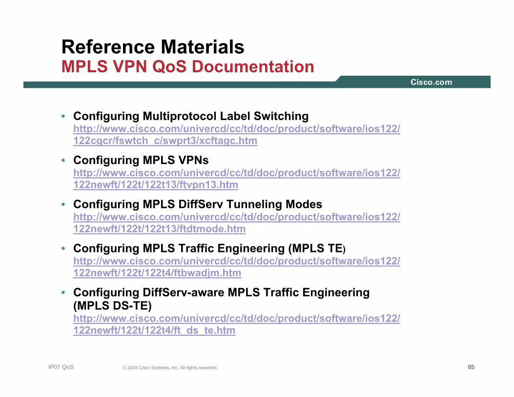
Reference MaterialsMPLS VPN QoS Documentation
• Configuring Multiprotocol Label Switchinghttp://www.cisco.com/univercd/cc/td/doc/product/software/ios122/122cgcr/fswtch_c/swprt3/xcftagc.htm
• Configuring MPLS VPNshttp://www.cisco.com/univercd/cc/td/doc/product/software/ios122/122newft/122t/122t13/ftvpn13.htm
• Configuring MPLS DiffServ Tunneling Modeshttp://www.cisco.com/univercd/cc/td/doc/product/software/ios122/122newft/122t/122t13/ftdtmode.htm
• Configuring MPLS Traffic Engineering (MPLS TE) http://www.cisco.com/univercd/cc/td/doc/product/software/ios122/122newft/122t/122t4/ftbwadjm.htm
• Configuring DiffServ-aware MPLS Traffic Engineering (MPLS DS-TE) http://www.cisco.com/univercd/cc/td/doc/product/software/ios122/122newft/122t/122t4/ft_ds_te.htm
868686© 2004 Cisco Systems, Inc. All rights reserved.IP07 QoS
Reference MaterialsAutoQoS Documentation
• AutoQoS VoIP for the Cisco Catalyst 2950http://www.cisco.com/univercd/cc/td/doc/product/lan/cat2950/12120ea2/2950scg/swqos.htm#wp1125412
• AutoQoS VoIP for the Cisco Catalyst 2970http://www.cisco.com/univercd/cc/td/doc/product/lan/cat2970/12220se/2970scg/swqos.htm#wp1231112
• AutoQoS VoIP for the Cisco Catalyst 3550http://www.cisco.com/univercd/cc/td/doc/product/lan/c3550/12120ea2/3550scg/swqos.htm#wp1185065
• AutoQoS VoIP for the Cisco Catalyst 3750http://www.cisco.com/univercd/cc/td/doc/product/lan/cat3750/12220se/3750scg/swqos.htm#wp1231112
• AutoQoS VoIP for the Cisco Catalyst 4550http://www.cisco.com/univercd/cc/td/doc/product/lan/cat4000/12_2_18/config/qos.htm#1281380
• AutoQoS VoIP for the Cisco Catalyst 6500 (Cisco Catalyst OS)http://www.cisco.com/univercd/cc/td/doc/product/lan/cat6000/sw_8_3/confg_gd/autoqos.htm
• AutoQoS VoIP for Cisco IOS Routers (Cisco IOS 12.2(15)T)http://www.cisco.com/univercd/cc/td/doc/product/software/ios122/122newft/122t/122t15/ftautoq1.htm
• AutoQoS Enterprise for Cisco IOS Routers (Cisco IOS 12.3(7)T)http://www.cisco.com/univercd/cc/td/doc/product/software/ios123/123newft/123t/123t_7/ftautoq2.htm
878787© 2004 Cisco Systems, Inc. All rights reserved.IP07 QoS
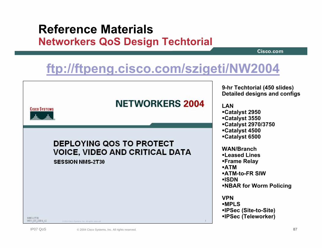
Reference MaterialsNetworkers QoS Design Techtorial
ftp://ftpeng.cisco.com/szigeti/NW20049-hr Techtorial (450 slides)Detailed designs and configs
LANCatalyst 2950Catalyst 3550Catalyst 2970/3750Catalyst 4500Catalyst 6500
WAN/BranchLeased LinesFrame RelayATMATM-to-FR SIWISDNNBAR for Worm Policing
VPNMPLSIPSec (Site-to-Site)IPSec (Teleworker)

888888© 2004 Cisco Systems, Inc. All rights reserved.IP07 QoS
Reference MaterialsCisco Press Book: End-to-End QoS Design
http://www.ciscopress.com/title/1587051761ISBN: 1587051761Publish Date: Nov 9/04
LANCatalyst 2950Catalyst 3550Catalyst 2970/3560/3750Catalyst 4500Catalyst 6500
WAN/BranchLeased LinesFrame RelayATMATM-to-FR SIWISDNNBAR for Worm Policing
VPNMPLS (for Enterprise Subscribers)MPLS (for Service Providers)IPSec (Site-to-Site)IPSec (Teleworker)

898989© 2004 Cisco Systems, Inc. All rights reserved.NMS-2T309681_05_2004_c2