qcs 2010 Section 16 Part 7 Accuracy of Fabrication
9
QCS 2010 Section 16 Part 7 Accuracy of Fabrication Page 1 QCS 2010 7. ACCURACY OF FA BRICATION .................................................................... 2 7.1 GENERAL ...................................................................................................... 2 7.1.1 Scope 2 7.1.2 References 2 7.2 PERMITTED DEVIATIONS ........................................................................... 2 7.2.1 Permitted Deviations In Rolled Components After Fabrication 2 7.2.2 Permitted Deviations for Elements of Fabricated Members 3 7.2.3 Permitted Deviations In Plate Girder Sections 5 7.2.4 Permitted Deviations in Box Sections 8
-
Upload
bryanpastor106 -
Category
Documents
-
view
226 -
download
0
Transcript of qcs 2010 Section 16 Part 7 Accuracy of Fabrication

8/10/2019 qcs 2010 Section 16 Part 7 Accuracy of Fabrication
http://slidepdf.com/reader/full/qcs-2010-section-16-part-7-accuracy-of-fabrication 1/9
QCS 2010 Section 16 Part 7 Accuracy of Fabrication Page 1
QCS 2010
7. ACCURACY OF FABRICATION .................................................................... 2
7.1 GENERAL ...................................................................................................... 2
7.1.1 Scope 2
7.1.2
References 2
7.2 PERMITTED DEVIATIONS ........................................................................... 2
7.2.1 Permitted Deviations In Rolled Components After Fabrication 2
7.2.2 Permitted Deviations for Elements of Fabricated Members 3
7.2.3 Permitted Deviations In Plate Girder Sections 5
7.2.4 Permitted Deviations in Box Sections 8
8/10/2019 qcs 2010 Section 16 Part 7 Accuracy of Fabrication
http://slidepdf.com/reader/full/qcs-2010-section-16-part-7-accuracy-of-fabrication 2/9
QCS 2010 Section 16 Part 7 Accuracy of Fabrication Page 2
QCS 2010
7. ACCURACY OF FABRICATION
7.1 GENERAL
7.1.1 Scope
1 This Part deals with the accuracy of fabrication of structural steel sections.
7.1.2 References
1 The following standards are referred to in this Part:
BS 4 Structural steel sectionsBS 4848 Hot rolled structural steel sectionsBS 5950 Structural use of steelwork in buildings
7.2 PERMITTED DEVIATIONS
7.2.1 Permitted Deviations In Rolled Components After Fabrication
1 Permitted deviations in rolled components after fabrication (including structural hollowsections) are given in Table 7.1
Table 7.1
Permitted Deviations in Rolled Components After Fabrication
Item Component Deviation
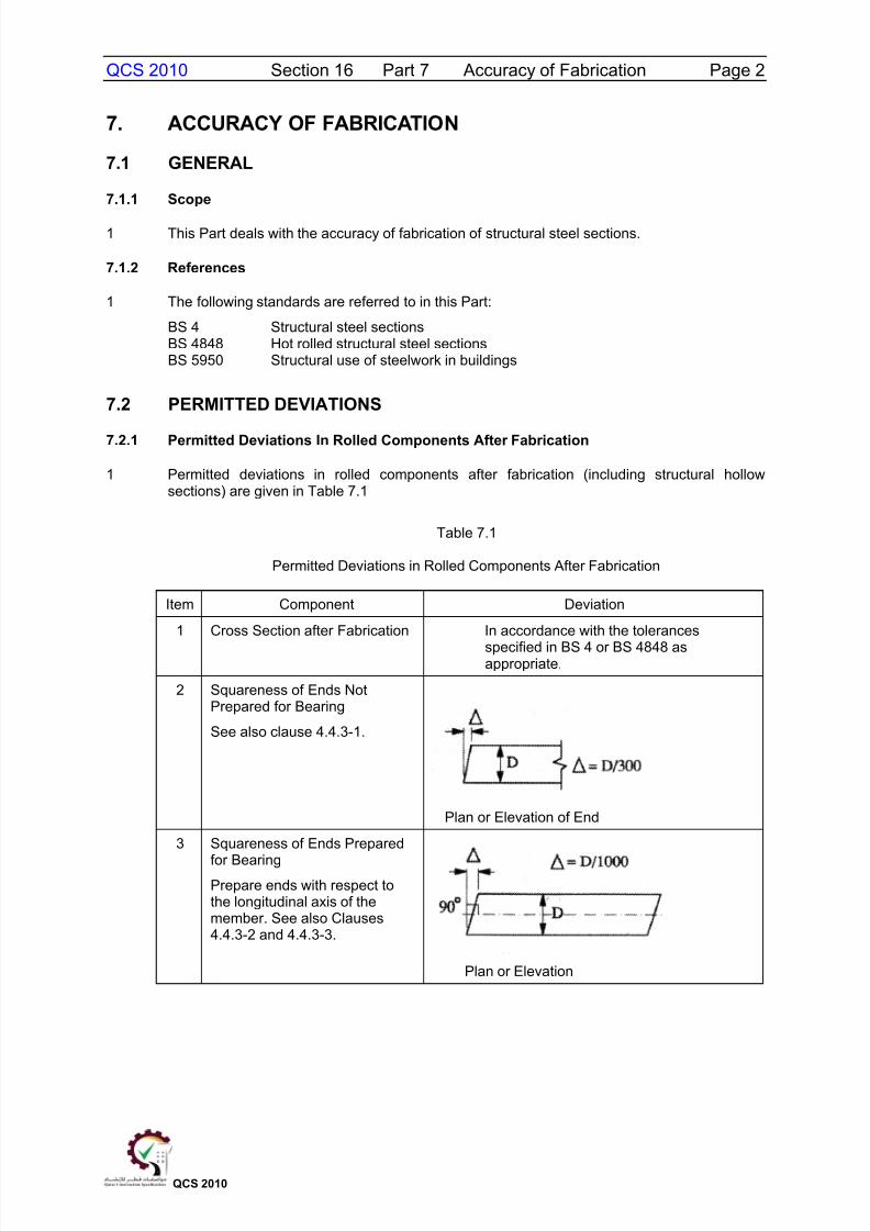
1 Cross Section after Fabrication In accordance with the tolerances
specified in BS 4 or BS 4848 asappropriate.
2 Squareness of Ends NotPrepared for Bearing
See also clause 4.4.3-1.
Plan or Elevation of End
3 Squareness of Ends Prepared
for BearingPrepare ends with respect tothe longitudinal axis of themember. See also Clauses4.4.3-2 and 4.4.3-3.
Plan or Elevation

8/10/2019 qcs 2010 Section 16 Part 7 Accuracy of Fabrication
http://slidepdf.com/reader/full/qcs-2010-section-16-part-7-accuracy-of-fabrication 3/9
QCS 2010 Section 16 Part 7 Accuracy of Fabrication Page 3
QCS 2010
Table 7.1 (Continued)
Permitted Deviations in Rolled Components After Fabrication
Item Component Deviation
4 Straightness on Both Axes
= L/1000 or 3mm
whichever is the greater
5 Length
Length after cutting,measured on the centre lineof the section of angles.
6 Curved or Cambered
Deviation from intended curveor camber at mid-length ofcurved portion whenmeasured with webhorizontal.
Deviation = L/1000 or 6mm
whichever is greater
7.2.2 Permitted Deviations for Elements of Fabricated Members
1 Permitted deviations for elements of fabricated members are given in Table 7.2
Table 7.2
Permitted Deviations for Elements of Fabricated Members
Item Component Deviation
1 Position of Fittings
Fittings and components whoselocation is crucial to the forcepath in the structure, thedeviation from the intended
position shall not exceed .

8/10/2019 qcs 2010 Section 16 Part 7 Accuracy of Fabrication
http://slidepdf.com/reader/full/qcs-2010-section-16-part-7-accuracy-of-fabrication 4/9
QCS 2010 Section 16 Part 7 Accuracy of Fabrication Page 4
QCS 2010
Table 7.2 (Continued)
Permitted Deviations for Elements of Fabricated Members
Item Component Deviation
2 Position of HolesThe deviation from the intendedposition of an isolated hole, alsoa group of holes, relative to each
other shall not exceed
3 Punched Holes
The distortion caused by apunched hole shall not exceed
(see clause 4.6.3)
= D/10 or 1mmwhichever is the greater
4 Sheared or Cropped Edges ofPlates or Angle
The deviation from a 90 edge
shall not exceed
5 Flatness
Where bearing is specified, theflatness shall be such that whenmeasured against a straightedge not exceeding one metrelong, which is laid against thefull bearing surface in anydirection, the gap does not
exceed
8/10/2019 qcs 2010 Section 16 Part 7 Accuracy of Fabrication
http://slidepdf.com/reader/full/qcs-2010-section-16-part-7-accuracy-of-fabrication 5/9
QCS 2010 Section 16 Part 7 Accuracy of Fabrication Page 5
QCS 2010
7.2.3 Permitted Deviations In Plate Girder Sections
1 Permitted deviations in plate girder sections are given in Table 7.3
Table 7.3
Permitted Deviations In Plate Girder Sections
Item Component Deviation
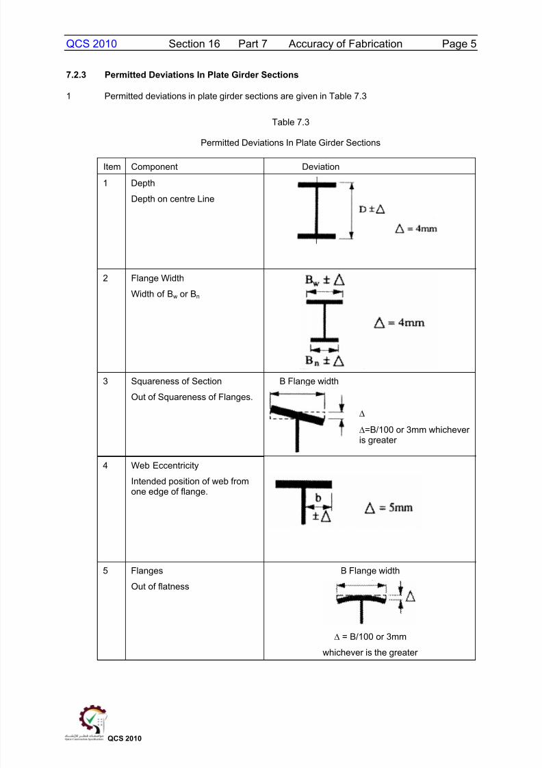
1 Depth
Depth on centre Line
2 Flange Width
Width of Bw or Bn
3 Squareness of Section
Out of Squareness of Flanges.
B Flange width
=B/100 or 3mm whicheveris greater
4 Web Eccentricity
Intended position of web fromone edge of flange.
5 Flanges
Out of flatness
B Flange width
= B/100 or 3mm
whichever is the greater
8/10/2019 qcs 2010 Section 16 Part 7 Accuracy of Fabrication
http://slidepdf.com/reader/full/qcs-2010-section-16-part-7-accuracy-of-fabrication 6/9
QCS 2010 Section 16 Part 7 Accuracy of Fabrication Page 6
QCS 2010
Table 7.3 (Continued)
Permitted Deviations In Plate Girder Sections
Item Component Deviation
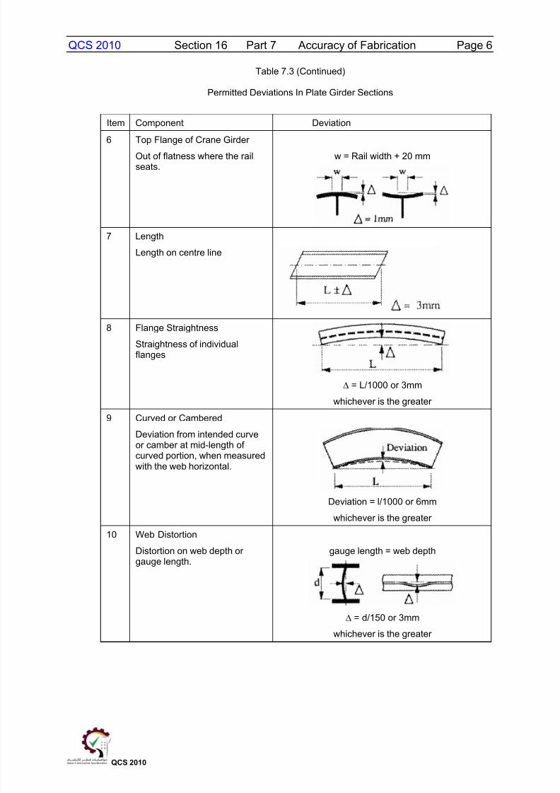
6 Top Flange of Crane Girder
Out of flatness where the railseats.
w = Rail width + 20 mm
7 Length
Length on centre line
8 Flange Straightness
Straightness of individualflanges
= L/1000 or 3mm
whichever is the greater
9 Curved or Cambered
Deviation from intended curveor camber at mid-length ofcurved portion, when measuredwith the web horizontal.
Deviation = l/1000 or 6mm
whichever is the greater
10 Web Distortion
Distortion on web depth orgauge length. gauge length = web depth
= d/150 or 3mm
whichever is the greater

8/10/2019 qcs 2010 Section 16 Part 7 Accuracy of Fabrication
http://slidepdf.com/reader/full/qcs-2010-section-16-part-7-accuracy-of-fabrication 7/9
QCS 2010 Section 16 Part 7 Accuracy of Fabrication Page 7
QCS 2010
Table 7.3 (Continued)
Permitted Deviations In Plate Girder Sections
Item Component Deviation
11 Cross Section at Bearings
Squareness of flanges to web
12 Web Stiffeners
Straightness of stiffener out of
plane after welding.
= d/500 or 3mm
whichever is greater
13 Web Stiffeners
Straightness of stiffener in planeafter welding.
= d/250 or 3mm
whichever is greater
8/10/2019 qcs 2010 Section 16 Part 7 Accuracy of Fabrication
http://slidepdf.com/reader/full/qcs-2010-section-16-part-7-accuracy-of-fabrication 8/9
QCS 2010 Section 16 Part 7 Accuracy of Fabrication Page 8
QCS 2010
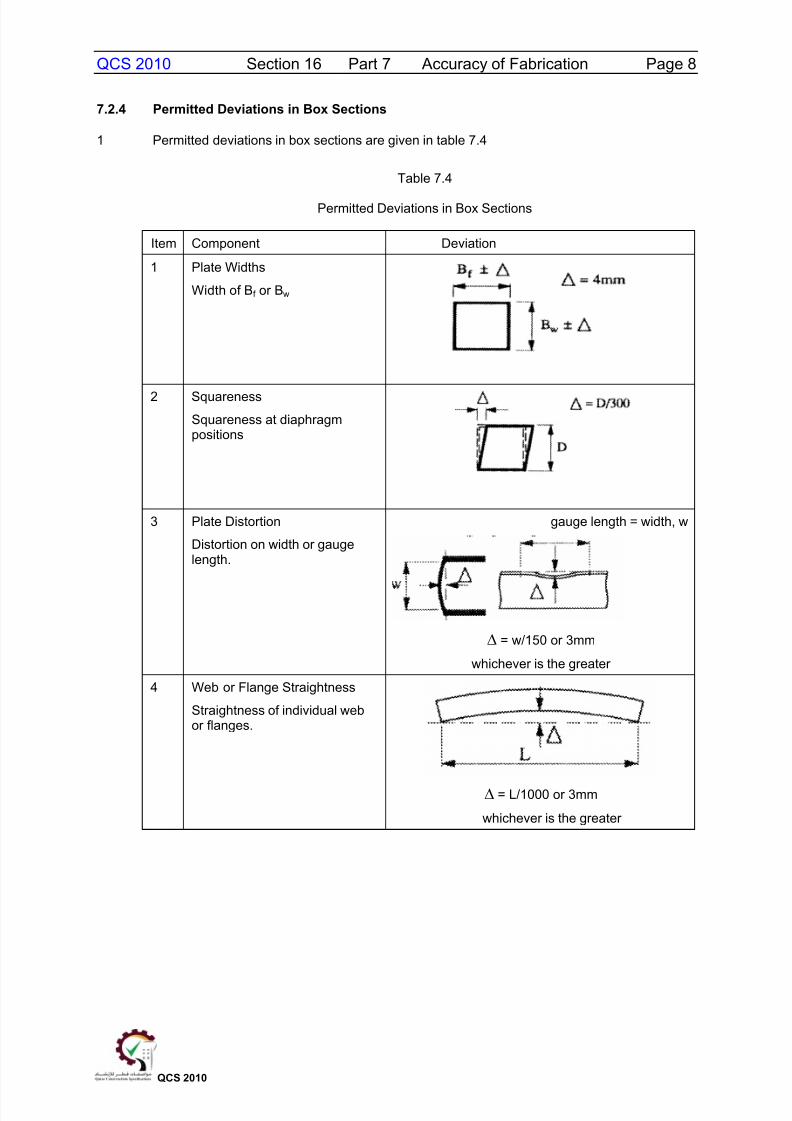
7.2.4 Permitted Deviations in Box Sections
1 Permitted deviations in box sections are given in table 7.4
Table 7.4
Permitted Deviations in Box Sections
Item Component Deviation
1 Plate Widths
Width of Bf or Bw
2 Squareness
Squareness at diaphragmpositions
3 Plate Distortion
Distortion on width or gaugelength.
gauge length = width, w
= w/150 or 3mm
whichever is the greater
4 Web or Flange Straightness
Straightness of individual webor flanges.
= L/1000 or 3mm
whichever is the greater

8/10/2019 qcs 2010 Section 16 Part 7 Accuracy of Fabrication
http://slidepdf.com/reader/full/qcs-2010-section-16-part-7-accuracy-of-fabrication 9/9
QCS 2010 Section 16 Part 7 Accuracy of Fabrication Page 9
QCS 2010
Table 7.4 (Continued)
Permitted Deviations in Box Sections
Item Component Deviation
5 Web StiffnersStraightness in plane with plateafter welding.
= d/500 or 3mm
whichever is the greater
6 Web StiffnersStraightness out of plane toplate after welding.
= d/250 or 3mm
whichever is the greater
7 Length
Length on centre line.
8 Curved or Cambered
Deviation from intended curveor camber at mid-length of
curved portion when measuredwith the uncambered sidehorizontal.
Deviation = L/1000 or 6mm
whichever is the greater
END OF PART