Justification Document for the Chilled Water Piping Installation

Manual 2100-416IPage 1 of 27
Manual No.: 2100-416ISupersedes: 2100-416HFile: Vol II Tab 14Date: 06-05-13
Bard Manufacturing Company, Inc.Bryan, Ohio 43506Since 1914...Moving ahead, just as planned.
QC SERIESCHILLED WATER UNITINSTALLATION
INSTRUCTIONSModel: QC501

Manual 2100-416IPage 2 of 27
CONTENTS
Getting Other Information and PublicationsFor more information, contact these publishers: ....... 3
QC General InformationQC Model Nomenclature .......................................... 4Shipping Damage ..................................................... 7Unit Removal From Skid ........................................... 7Handling Unit After Removal From Skid ................... 7Removal of Wall Bracket from Shipping Location ..... 8General ..................................................................... 8Minimum Installation Height ...................................... 8Duct Work ............................................................... 11Filters ...................................................................... 11Condensate Drain ...........................................12 & 13Mist Eliminator Service ........................................... 13
Figures Figure 1 Unit Dimensions ...................................... 6 Figure 2 Removal of Unit From Skid ..................... 7 Figure 3 Proper Handling of Unit After Removal from Skid ................................................. 8 Figure 4 Installation of Unit w/Wall Sleeve ............ 9 Figure 5 Installation With Free Blow Plenum ...... 10 Figure 6 Ducted Application ................................ 10 Figure 7 Supply Duct Connections ...................... 11 Figure 8 Filter Location ....................................... 11 Figure 9A Side Drain (Side View) .......................... 12 Figure 9B Optional Rear Drain .............................. 12 Figure 9C Rear Drain (Top View) ........................... 12 Figure 10 Fresh Air Damper Removal ................... 14 Figure 11 Removal of QTec ERV .......................... 15 Figure 12 Remove Locking Screws from Wheels . 16 Figure 13 Unit Mounting Without Wall Sleeve ....... 17 Figure 14 Component Location ............................. 18 Figure 15 Low Voltage Wire Harness Plug ........... 20 Figure 16 Remote Thermostat Wiring "X" Option .. 21 Figure 17 Remote Thermostat Wiring "D" Option . 22 Figure 18 Control Disassembly ............................. 25 Figure 19 Winding Test .......................................... 25 Figure 20 Drip Loop .............................................. 25 Figure 21 Internal 2-Way Valve Piping .................. 26 Figure 22 Internal 3-Way Valve Piping .................. 27
TablesTable 1 Factory Built-In Electric Heat ..................... 4Table 2 Electrical Specifications ............................. 4Table 2A Cooling Performance Chart ....................... 5Table 3 Operating Voltage Range ........................ 19Table 4 Wall Thermostat ...................................... 19Table 5 Indoor Blower Performance ..................... 23
Installation InstructionsMounting the Unit .................................................... 16Wiring – Main Power .......................................18 & 19Wiring – Low Voltage Wiring ................................... 19General Information ................................................ 19Fluid Connections ................................................... 19Low Voltage Connections ....................................... 20
Start UpOptional CFM ......................................................... 23Important Installer Note ........................................... 23Service Hints ........................................................... 23Sequence of Operation ........................................... 23
Troubleshooting ECM Motors .........................24-25

Manual 2100-416IPage 3 of 27
GETTING OTHER INFORMATION AND PUBLICATIONS
These publications can help you install the air conditioner or heat pump. You can usually find these at your local library or purchase them directly from the publisher. Be sure to consult current edition of each standard.
National Electrical Code .......................ANSI/NFPA 70
Standard for the Installation ...............ANSI/NFPA 90A of Air Conditioning and Ventilating Systems
Standard for Warm Air .......................ANSI/NFPA 90B Heating and Air Conditioning Systems
Load Calculation for Residential ......ACCA Manual J Winter and Summer Air Conditioning
Duct Design for Residential ..............ACCA Manual D Winter and Summer Air Conditioning and Equipment Selection
Closed-Loop/Ground Source Heat Pump ........IGSHPA Systems Installation Guide
Grouting Procedures for Ground-Source .........IGSHPA Heat Pump Systems
Soil and Rock Classification for the Design ....IGSHPA of Ground-Coupled Heat Pump Systems
Ground Source Installation Standards .............IGSHPA
Closed-Loop Geothermal Systems – Slinky ....IGSHPA Installation Guide
FOR MORE INFORMATION, CONTACT THESE PUBLISHERS: ACCA Air Conditioning Contractors of America 1712 New Hampshire Avenue Washington, DC 20009 Telephone: (202) 483-9370 Fax: (202) 234-4721
ANSI American National Standards Institute 11 West Street, 13th Floor New York, NY 10036 Telephone: (212) 642-4900 Fax: (212) 302-1286
ASHRAE American Society of Heating Refrigerating, and Air Conditioning Engineers, Inc. 1791 Tullie Circle, N.E. Atlanta, GA 30329-2305 Telephone: (404) 636-8400 Fax: (404) 321-5478
NFPA National Fire Protection Association Batterymarch Park P.O. Box 9101 Quincy, MA 02269-9901 Telephone: (800) 344-3555 Fax: (617) 984-7057
IGSHPA International Ground Source Heat Pump Association 490 Cordell South Stillwater, OK 74078-8018

Manual 2100-416IPage 4 of 27
Models
KW
QC501-A240V-1 208V-1
BTUH BTUH
5.0 16,380 12,290
10.0 32,670 24,570
15.0 49,150 36,860
Models
SINGLE CIRCUIT DUAL CIRCUIT
RatedVolts &Phases
No.Field
PowerCircuits
MinimumCircuit
Ampacity
MaximumExternalFuse orCircuit
Breaker
FieldPowerWireSize
GroundWireSize
MinimumCircuit
Ampacity
MaximumExternalFuse orCircuit
Breaker
FieldPowerWireSize
GroundWireSize
CKTA
CKTB
CKTA
CKTB
CKTA
CKTB
CKTA
CKTB
QC501-A0Z-A05-A10-A15
230/208-1
111
1 or 2
7335883
15356090
14864
1410108
–––50
–––33
–––50
–––40
–––8
–––8
–––10
–––10
QC501-K0Z 115-1 1 10 15 14 14 – – – – – – – –
QC SERIES WATER SOURCE GENERAL INFORMATIONQC MODEL NOMENCLATURE
QC 50 1 – A 10 X X X X X X
TABLE 1FACTORY BUILT-IN ELECTRIC HEAT TABLE
Maximum size of the time delay fuse or HACR type circuit breaker for protection of field wiring conductors.Based on 75°C copper wire. All wiring must conform to the National Electrical Code and all local codes.These “Minimum Circuit Ampacity” values are to be used for sizing the field power conductors. Refer to the National Electric Code (latest revision), article 310 for power conductor sizing.
CAUTION: When more than one field power conductor circuit is run through one conduit, the conductors must be derated. Pay special attention to Note 8 of Table 310 regarding Ampacity Adjustment Factors when more than three conductors are in a raceway.
TABLE 2ELECTRICAL SPECIFICATIONS
Ventilation OptionB - Blank Off Plate (no ventilation)X - Barometric Fresh Air Damper (no exhaust)V - Commercial Ventilator (w/Exhaust)P - Commercial Ventilator (w/Exhaust) Motorized, Power ReturnR - Energy Recovery Ventilator (w/Exhaust) - 230/208-60-1 versions only
KW 0Z - 0 KW05 - 5 KW10 - 10 KW15 - 15 KW (Note 1)
Volts & PhaseA - 230/208-60-1K - 115-60-1
RevisionCapacity50 - 4 ton
Model NumberQC - QTec™ Model
Filter OptionsX - 1-Inch Fiberglass (Standard)F - 2-Inch FiberglassP - 2-Inch pleated
Color V - Platinum w/Slate Front (vinyl)4 - Gray Paint Climate Control
X - NoneD - Electronic/prog/man/auto
Internal ControlsX - None
Valve Options4 - 2-way valve5 - 3-way valve
NOTE 1: Electric heat available for -A models only

Manual 2100-416IPage 5 of 27
GPM EWT CFM
BTUH Capacity (1000) BTUH Capacity (1000) Water Coil Pressure DropStage 1 Stage 1 and 2
Total Sensible Latent Total Sensible Latent PSIG Ft. Hd.
6
42 1000
15.1 10.5 4.6 38.5 25.3 13.2 1.9 4.4
8 16.4 11.1 5.3 41.5 26.8 14.7 3.3 7.5
10 17.4 11.7 5.7 43.2 27.4 15.8 4.9 11.3
6
44 1000
13.9 10.0 3.9 35.8 24.2 11.6 1.9 4.4
8 15.1 10.6 4.5 38.4 25.4 13.0 3.3 7.5
10 16.0 11.1 4.9 40.0 26.0 14.0 4.9 11.3
6
46 1000
12.8 9.6 3.2 33.0 23.0 10.0 1.9 4.4
8 13.9 10.1 3.8 35.3 24.0 11.3 3.3 7.5
10 14.7 10.6 4.1 36.9 24.6 12.3 4.9 11.3
6
48 1000
11.6 9.1 2.5 30.3 21.9 8.4 1.9 4.4
8 12.6 9.6 3.0 32.2 22.6 9.6 3.3 7.5
10 46.6 10.0 3.3 33.7 23.2 10.5 4.9 11.3
6
42 1200
15.9 11.5 4.4 42.1 29.0 13.1 1.9 4.4
8 17.4 12.2 5.2 46.0 30.6 15.4 3.3 7.5
10 18.8 12.8 6.0 49.3 31.9 17.4 4.9 11.3
6
44 1200
14.8 11.1 3.7 39.3 27.7 11.6 1.9 4.4
8 16.2 11.7 4.5 42.7 29.2 13.5 3.3 7.5
10 17.4 12.3 5.1 45.6 30.4 15.2 4.9 11.3
6
46 1200
13.6 10.7 2.9 36.4 26.5 9.9 1.9 4.4
8 14.9 11.3 3.6 39.5 27.9 11.6 3.3 7.5
10 16.1 11.7 1.1 42.0 29.0 13.0 4.9 11.3
6
48 1200
12.5 10.3 2.2 33.6 25.2 8.4 1.9 4.4
8 13.7 10.8 2.9 36.2 26.5 9.7 3.3 7.5
10 14.7 11.2 3.5 38.3 27.5 10.8 4.9 11.3
TABLE 2ACOOLING PERFORMANCE CHART

Manual 2100-416IPage 6 of 27
FIG
UR
E 1
U
NIT
DIM
ENSI
ON
S

Manual 2100-416IPage 7 of 27
SHIPPING DAMAGEUpon receipt of equipment, the carton should be checked for external signs of shipping damage. The skid must remain attached to the unit until the unit is ready for installation. If damage is found, the receiving party must contact the last carrier immediately, preferably in writing, requesting inspection by the carrier’s agent.
It is recommended that the unit not be removed from the skid with a forklift.
The shipping brackets on each side of the unit must be removed and discarded. See Figure 2-A on Page 7. The return air grille panel can be removed to provide a place to hold the unit. The unit can be slid forward on the skid until the front wheels hang over the edge of the skid. See Figure 2-B. The unit can be tipped forward and slid down the edge of the skid until the front wheels touch the ground. See Figure 2-C. The wheels will not roll. They are shipped from the factory locked so they will not roll. The back of the skid will have to be held down to keep it from tipping up. The skid can be slid out from under the unit. The unit can then be set upright. FIGURE 2
REMOVAL OF UNIT FROM SKID
HOLD SKID DOWN
A SHIPPING BRACKETS B FRONT WHEELS OVER EDGE C FRONT WHEELS ON FLOOR
The unit will have to be turned sideways and removed from the skid to fit through a 36" doorway. If the door height allows, the unit can be slid sideways through the door.
If the unit can not be slid through the door, then the unit will have to be put on a cart and tipped down to roll through the door. It is recommended that an appliance cart by used with a strap to hold the unit on the cart. The wheels of the unit must be locked. If the wheels were allowed to roll, the unit could roll off the cart. The blade of the appliance cart should be slid under the wheels of the unit. See Figure 3. The strap of the appliance cart should be placed around the unit and strapped tightly. Help will be required to tip the unit back onto the cart. The unit can be leaned far enough back to be rolled through the door. Be careful when setting the unit back up to keep from damaging the unit.
UNIT REMOVAL FROM SKID
HANDLING UNIT AFTER REMOVAL FROM SKID
WARNINGExercise extreme caution when pushing the unit on the rollers. Handle and push from the lower 1/3 of the unit. Insure that debris is not on the floor where the unit is to be moved on the rollers. Failure to do so could result in the unit tipping over and causing bodily injury and/or damage to the unit. WARNING
This unit is heavy and requires more than one person to handle and remove from the skid. Check unit wheels to insure that wheels are locked before removing from skid. Extreme caution must be taken to prevent injury to personnel and damage to the unit.

Manual 2100-416IPage 8 of 27
REMOVAL OF WALL BRACKET FROM SHIPPING LOCATIONThe wall brackets are attached to the back of the unit. Remove and retain the wall brackets for use when attaching the unit to the wall. In those installations where a wall sleeve is required these two wall brackets are to be discarded. A different style bracket is supplied with the sleeve assembly.
GENERALThe equipment covered in this manual is to be installed by trained, experienced service and installation technicians.
The unit is designed for use with or without duct work. For use without duct work, Plenum Box QPB** is recommended.
These instructions explain the recommended method to install the water source self-contained unit and the electrical wiring connections to the unit.
These instructions and any instructions packaged with any separate equipment required to make up the entire air conditioning system should be carefully read before beginning the installation. Note particularly “Start Procedure” and any tags and/or labels attached to the equipment.
While these instructions are intended as a general recommended guide, they do not supersede any national and/or local codes in any way. Authorities having jurisdiction should be consulted before the installation is made. See Page 3 for information on codes and standards.
Size of unit for a proposed installation should be based on heat loss calculation made according to methods of Air Conditioning Contractors of America (ACCA). The air duct should be installed in accordance with the Standards of the National Fire Protection Systems of Other Than Residence Type, NFPA No. 90A, and Residence Type Warm Air Heating and Air Conditioning Systems, NFPA No. 90B. Where local regulations are at a variance with instructions, installer should adhere to local codes.
MINIMUM INSTALLATION HEIGHTThe minimum installation height of the unit with a Free Blow Plenum is 8 ft. 6 in. This provides enough clearance for the plenum to be removed. See Figure 5.
The minimum installation height for ducted applications is 8 ft. 4½ in. This provides enough clearance to install the duct work. See Figure 6.
FIGURE 3PROPER HANDLING OF UNIT AFTER REMOVAL FROM SKID
QTec UNIT(RIGHT SIDE)
STRAP
APPLIANCE CART

Manual 2100-416IPage 9 of 27
FIGURE 4INSTALLATION OF UNIT THROUGH WALL WITH WALL SLEEVE

Manual 2100-416IPage 10 of 27
FIGURE 6DUCTED APPLICATION
FIGURE 5INSTALLATION WITH FREE BLOW PLENUM
CEILING
FLOOR
FLOOR

Manual 2100-416IPage 11 of 27
DUCT WORKAny heat pump is more critical of proper operating charge and an adequate duct system than a straight air conditioning unit. All duct work must be properly sized for the design airflow requirement of the equipment. Air Conditioning Contractors of America (ACCA) is an excellent guide to proper sizing. All duct work or portions thereof not in the conditioned space should be properly insulated in order to both conserve energy and prevent condensation or moisture damage. When duct runs through unheated spaces, it should be insulated with a minimum of one inch of insulation. Use insulation with a vapor barrier on the outside of the insulation. Flexible joints should be used to connect the duct work to the equipment in order to keep the noise transmission to a minimum.
The QTec series unit has provision to attach a supply air duct to the top of the unit. Duct connection size is 12 inches x 20 inches. The duct work is field supplied and must be attached in a manner to allow for ease of removal when it becomes necessary to slide the unit out from the wall for service. See Figure 7 for suggested attachment method.
NOTE: Unit cabinet, supply air duct and free blow plenum are approved for “0” clearance to combustible material.
The QTec series units are designed for use with free return (non-ducted) and either free blow with the use of QPB Plenum Box or a duct supply air system.
The QPB Plenum Box mounts on top of the unit and has both vertically and horizontally adjustable louvers on the front discharge grille.
FIGURE 7SUPPLY DUCT CONNECTIONS
When used with a ducted supply, a QCX Cabinet Extension can be used to conceal the duct work above the unit to the ceiling. This extends 20" above the unit for a total height above the floor of 10'-7/8". See Spec. Sheet for the correct Cabinet Extension model number. The unit is equipped with a variable speed indoor blower motor, which increases in speed with an increase in duct static pressure. The unit will therefore deliver proper rated airflow up to the Maximum ESP shown in Table 5. However, for quiet operation of the air system, the duct static should be kept as low as practical, within the guidelines of good duct design.
FILTERSTwo 1-inch throw away filters are supplied with each unit. The filters fit into a fixed rack.
The filters are serviced from the inside of the building. To gain access to the filters release the latch on the circuit breaker door and one 1/4 turn fastener near the bottom of the door. This door is hinged on the left so it will swing open.
The internal filter brackets are adjustable to accommodate 2-inch filters. The tabs for the 1-inch filters must be bent down to allow the 2-inch filters to slide in place.
SUPPLY DUCT TO BE FIELD SUPPLIED
ATTACHMENT SCREWS TO BE FIELD SUPPLIED
DUCT FLANGE PROVIDED WITH UNIT
ROOM SIDE OF QC UNIT
FIGURE 8 FILTER LOCATION
RETURN AIR GRILLE
FILTERS

Manual 2100-416IPage 12 of 27
CONDENSATE DRAINThe condensate drain hose is routed down from the evaporator drain pan on the right side of the unit into the compressor compartment. There are three locations that the drain can exit the cabinet. For a stand pipe type of drain, the drain hose can exit the rear of the cabinet. There is adequate hose length to reach the floor on the right hand side of the unit.
If the drain is to be hard plumbed, there is a 3/4 inch pipe connection located on the right hand cabinet side near the rear and one on the cabinet rear panel. In these installations the drain tube is to be slipped over the pipe connection inside of the cabinet.
FIGURE 9BOPTIONAL REAR DRAIN
See Figures 9A, 9B and 9C.
NOTE: Whichever type of drain connection is used a “P” trap must be formed.
The side drain requires a water trap for proper drainage. See Figure 9A. The drain can be routed through the floor or through the wall. If the drain is to be routed through an unconditioned space, it must be protected from freezing. The drain line must be able to be removed from the unit if it is necessary to remove the unit from the wall.
FIGURE 9ASIDE DRAIN (SIDE VIEW)
FIGURE 9CREAR DRAIN (TOP VIEW)
SLEEVE
WALL BRACKET
WALL (MAXIMUM 10" FOR REAR DRAIN)
DRAIN LINE
COUPLINGS NOT SHOWN BUT RECOMMENDED FOR EASE OF REMOVABILITY FOR SERVICE
WATER TRAP
UNIT
QTec UNIT

Manual 2100-416IPage 13 of 27
BAROMETRIC FRESH AIR DAMPER (Optional)
Before start to remove make sure the power has been turned off. The hinged return air grille panel must be opened. The fresh air damper assembly can be seen on the back of the unit. Refer to Figure 10.
1. The fresh air damper is attached to the back of the unit with one screw on either side of the assembly. Both of the screws must be removed.
2. Once the mounting screws are removed, tilt the assembly down and lift it out.
The mist eliminator can be seen through the opening. The mist eliminator must be raised up and the bottom can be pulled toward the front of the unit.
COMMERCIAL ROOM VENTILATOR OPTION
Before stating the removal make sure the power has been turned off. The hinged return air grille must be opened. The commercial room ventilator (CRV) can be seen after the panel has been removed. The CRV must be removed to gain access to the mist eliminator.
1. The two mounting screws in the front of the CRV must be removed.
2. The power connectors for the CRV (located on the right side of the unit) must be disconnected. Squeeze the tabs on the sides of the connector and pull straight out. Unplug both of the connectors.
3. Slide the CRV straight out of the unit.
The mist eliminator can be seen through the opening in the back of the unit. The mist eliminator must be raised up and the bottom can be pulled toward the front of the unit and removed.
The rear drain can be used with wall thickness of up to 10 inches where a water trap can be installed between the unit and the interior wall. See Figure 9B. The trap cannot extend beyond the edge of the unit or it will interfere with the wall mounting bracket. The drain can be routed through the floor or through the wall. If the drain is routed through the wall, the drain line must be positioned such that it will not interfere with the sleeve flange or the grille. See Figure 9C on Page 12. If the drain is to be routed through an unconditioned space, it must be protected from freezing.
MIST ELIMINATOR SERVICE (Optional – only used with one of the vent options)A mist eliminator is supplied with the wall sleeve. The mist eliminator is constructed of aluminum frame and mesh. The mist eliminator is located in the top section of the wall sleeve and can be removed from the inside of the building without removing the unit from the wall. This requires that the ventilation package must be removed.
The steps necessary to remove each of the vent options are listed following.
It is recommended that the mist eliminator be inspected annually and serviced as required. The mist eliminator can be inspected from the outside of the building by looking through the outdoor grille. The mist eliminator can be serviced from the outside. The outdoor grille must be removed to do so.
The mist eliminator can be cleaned by washing with soap and water. The excess water should be shaken off the mist eliminator before it is reinstalled.

Manual 2100-416IPage 14 of 27
FIGURE 10FRESH AIR DAMPER REMOVAL
MOUNTING SCREW

Manual 2100-416IPage 15 of 27
QTEC ENERGY RECOVERY VENTILATOR OPTION
Before starting the removal make sure that the power has been turned off. The hinged return air grille panel must be opened. The energy recovery ventilator (QERV) can be seen after the panel is opened. To gain access to the mist eliminator, the QERV must be removed. Refer to Figure 11.
1. The front fill plate of the QERV must be removed. There is one screw on either side of the plate. Remove these screws and remove the plate.
2. On either side of the QERV there are mounting screws that hold the QERV in place. Remove both of these screws.
FIGURE 11REMOVAL OF THE QTEC ENERGY RECOVERY VENTILATOR
3. Underneath the heat recovery cassette there is a power connector for the lower blower assembly. To disconnect this plug, the tabs on both sides of the plug must be squeezed to release the plug. While squeezing the tabs, pull the plug out of the socket.
4. The QERV is plugged into the unit on the right side of the unit. Both of these plugs must be disconnected to remove the QERV. Squeeze the tabs on the sides of the connector and pull straight out.
5. Slide the QERV assembly straight out of the unit being careful not to let the cassette slide out of the QERV.
The mist eliminator can be seen through the opening in the back of the unit. The mist eliminator must be raised up and the bottom can be pulled toward the front of the unit and removed.
FRONT FILL
MOUNTING SCREWS
LOWER BLOWERASSEMBLY POWER CONNECTOR
POWER CONNECTORS

Manual 2100-416IPage 16 of 27
INSTALLATION INSTRUCTIONS
MOUNTING THE UNITWhen installing a QC unit near an interior wall on the left side, a minimum of 8 inches is required; 12 inches is preferred.
When installing a QC unit near an interior wall on the right side, a minimum of 12 inches is required as additional space is required to connect the drain.
This clearance is required to allow for the attachment of the unit to the wall mounting brackets and the side trim pieces to the wall.
This unit is to be secured to the wall with the wall mounting brackets provided. The unit itself, the supply duct, and the free blow plenum are suitable for “0” clearance to combustible material.
NOTE: When a wall sleeve is to be used discard the brackets shipped with the heat pump and attache the unit to the sleeve with bracket supplied with the wall sleeve.
Following are the steps for mounting the QC units for reference see Figure 13.
1. Attach wall mounting bracket to the structure wall with field supplied lag bolts. The fluid piping connections are to be within the confines of this bracket. See Figure 1 for cabinet openings and location of fluid coil connection points.
2. Position the unit in front of the wall mounting bracket.
3. Remove the locking screws from the wheels. Refer to Figure 12.
4. Roll the unit up to the wall mounting bracket. The unit must be level from side to side. If any adjustments are necessary, shim up under the rollers with sheets of steel or any substance that is not affected by moisture.
5. Secure the unit to the wall bracket with provided #10 hex head sheet metal screws. There are prepunched holes in the cabinet sides, and the bracket has slotted holes to allow for some misalignment.
6. Position the bottom trim piece to the unit and attach with provided screws (dark colored).
7. Position side trim pieces to the wall and attach with field supplied screws. There are two long and two short pieces supplied. The long pieces are to enclose the gap behind the unit. The short pieces are to fill the gap behind the cabinet extension or the free blow plenum box. They may be cut to suit the ceiling height or overlap the unit side trim. There is sufficient length to trim up to a 10'2" ceiling.
FIGURE 12REMOVING LOCKING SCREWS FROM
WHEELS
REMOVE SCREWS FROM WHEELS BEFORE ROLLING INTO PLACE

Manual 2100-416IPage 17 of 27
FIGURE 13UNIT MOUNTING WITHOUT VENTILATION WALL SLEEVE
(REFER TO MOUNTING INSTRUCTIONS ON PAGE 16)
SIDE TRIM (2 PIECES)
SIDE TRIM (2 PIECES)
WALL MOUNTING BRACKET
BOTTOM TRIM EXTENSIONBOTTOM TRIM PIECE

Manual 2100-416IPage 18 of 27
FIGURE 14COMPONENT LOCATION
SIDE FIELD WIRE ENTRANCE
REMOTE THERMOSTAT TERMINAL BLOCK
INDOOR BLOWER
CONTROL BOX/ CIRCUIT BREAKER PANEL
WIRING – MAIN POWERRefer to the unit rating plate and/or Table 2 for wire sizing information and maximum fuse or “HACR Type” circuit breaker size. Each unit is marked with a “Minimum Circuit Ampacity”. This means that the field wiring used must be sized to carry that amount of current. Depending on the installed KW of electric heat, there may be two field power circuits required. If this is the case, the unit serial plate will so indicate. All models are suitable only for connection with copper wire. Each unit and/or wiring diagram will be marked
“Use Copper Conductors Only”. These instructions must be adhered to. Refer to the National Electrical Code (NEC) for complete current carrying capacity data on the various insulation grades of wiring material. All wiring must conform to NEC and all local codes.
The electrical data lists fuse and wire sizes (75°C copper) for all models, including the most commonly used heater sizes. Also shown are the number of field power circuits required for the various models with heaters.
Manual 2100-416IPage 19 of 27
TAP RANGE240V 253 - 216
208V 220 - 18
Thermostat Predominant Features
8403-060(1120-445)
3 stage Cool; 3 stage HeatProgrammable/Non-Programmable ElectronicHP or ConventionalAuto or Manual changeover
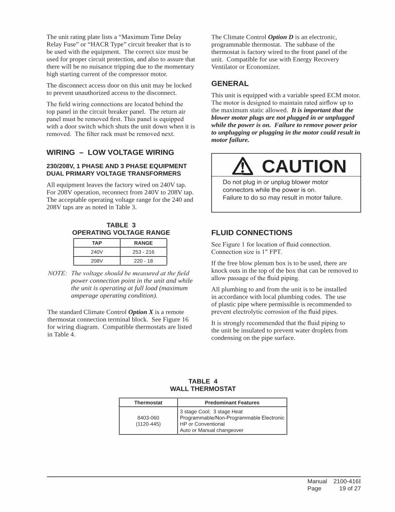
The unit rating plate lists a “Maximum Time Delay Relay Fuse” or “HACR Type” circuit breaker that is to be used with the equipment. The correct size must be used for proper circuit protection, and also to assure that there will be no nuisance tripping due to the momentary high starting current of the compressor motor.
The disconnect access door on this unit may be locked to prevent unauthorized access to the disconnect.
The field wiring connections are located behind the top panel in the circuit breaker panel. The return air panel must be removed first. This panel is equipped with a door switch which shuts the unit down when it is removed. The filter rack must be removed next.
WIRING – LOW VOLTAGE WIRING
230/208V, 1 PHASE AND 3 PHASE EQUIPMENT DUAL PRIMARY VOLTAGE TRANSFORMERS
All equipment leaves the factory wired on 240V tap. For 208V operation, reconnect from 240V to 208V tap. The acceptable operating voltage range for the 240 and 208V taps are as noted in Table 3.
The Climate Control Option D is an electronic, programmable thermostat. The subbase of the thermostat is factory wired to the front panel of the unit. Compatible for use with Energy Recovery Ventilator or Economizer.
GENERALThis unit is equipped with a variable speed ECM motor. The motor is designed to maintain rated airflow up to the maximum static allowed. It is important that the blower motor plugs are not plugged in or unplugged while the power is on. Failure to remove power prior to unplugging or plugging in the motor could result in motor failure.
NOTE: Thevoltageshouldbemeasuredatthefieldpower connection point in the unit and while the unit is operating at full load (maximum amperage operating condition).
TABLE 3 OPERATING VOLTAGE RANGE
TABLE 4WALL THERMOSTAT
FLUID CONNECTIONSSee Figure 1 for location of fluid connection. Connection size is 1" FPT.
If the free blow plenum box is to be used, there are knock outs in the top of the box that can be removed to allow passage of the fluid piping.
All plumbing to and from the unit is to be installed in accordance with local plumbing codes. The use of plastic pipe where permissible is recommended to prevent electrolytic corrosion of the fluid pipes.
It is strongly recommended that the fluid piping to the unit be insulated to prevent water droplets from condensing on the pipe surface.
The standard Climate Control Option X is a remote thermostat connection terminal block. See Figure 16 for wiring diagram. Compatible thermostats are listed in Table 4.
CAUTIONDo not plug in or unplug blower motor connectors while the power is on.Failure to do so may result in motor failure.

Manual 2100-416IPage 20 of 27
LOW VOLTAGE CONNECTIONS
These units use a grounded 24 volt AC low voltage circuit.
The “R” terminal is the hot terminal and the “C” terminal is grounded.
“G” terminal or pins 6 and 1 of P2 are the fan inputs. Both must be energized for proper fan operation. This is done automatically in the factory installed climate control options. If the climate control option is abandoned and connections are made directly to P2 both pins 6 and 1 of P2 must be energized for proper operation.
“Y1” terminal or pin 7 of P2 is the firststagecoolinginput.
“W1” terminal or pin 8 of P2 is the firststageheatinginput.
“R” terminal or pin 10 of P2 is 24 VAC hot.
“C” terminal or pin 11 of P2 is 24 VAC grounded.
“Y2” terminal or pin 12 of P2 is the second stage cooling input.
“W2” terminal or pin 9 of P2 is second stage heating output.
“3” terminal of pin 5 of P2 is the ventilation input. This terminal energizes any factory installed ventilation option.
Fan Only Energize G
1st Cooling Mode Energize Y1, G
2nd Cooling Mode Energize Y1, Y2, G
1st Stage Heating Energize G, W1
2nd Stage Heating Energize G, W1, W2
Ventilation Energize G, 3
LOW VOLTAGE CONNECTIONS FOR DDC CONTROL
FIGURE 15BLOWER MOTOR LOW VOLTAGE
WIRE HARNESS PLUG
MIS-1285

Manual 2100-416IPage 21 of 27
FIGURE 16REMOTE THERMOSTAT WIRING DIAGRAM
“X” OPTION

Manual 2100-416IPage 22 of 27
FIGURE 17 REMOTE THERMOSTAT WIRING DIAGRAM
“D” THERMOSTAT OPTION

Manual 2100-416IPage 23 of 27
MODELRATED
ESP
MAX. ESP
RATED CFM
OPTIONAL
CFM
CONTINUOUS
CFMCFM @ MAX.
ESPQC501 0.0 0.8 1200 1000 1000 1175
Maximum ESP (inches WC) shown is with 1" thick disposable filter (reduced by .2 for 2" filter). Rated CFM for ducted applications – required for maximum performance rating. To obtain full CFM locate low voltage terminal strip in the circuit breaker box. There is a pink jumper wire with both ends attached to terminal marked “G2”. Move one end of the jumper to terminal “Y1”. Optional CFM – the unit is shipped from the factory set to operate at the optional CFM level shown. This provides lower operating sound levels for non-ducted, free discharge applications . This reduces system capacity performance by approximately 2% at the same energy efficiency. Continuous fan CFM is the total air being circulated during continuous fan mode.
OPTIONAL CFM These units are shipped from the factory set to operate at the optional CFM level shown in Table 5. This provides lower operating sound levels for non-ducted, free discharge applications. This CFM level will reduce the system capacity performance by approximately 2% at the same energy efficiency.Rated CFM is required for ducted applications for maximum performance rating. To obtain full CFM on these models, connect jumper wire as follows:
1. Disconnect all power to the unit. Failure to do so may result in damage to the motor.
2. Open hinged return air grille panel.
3. Open control panel cover.
4. Add pink jumper wire (provided) to terminal 5 and 6 on the terminal board.
5. Reverse steps to reassemble.
IMPORTANT INSTALLER NOTEFor improved start up performance, wash the indoor coil with dishwashing detergent.
SERVICE HINTS 1. Caution user to maintain clean air filters at all times.
Also, not to needlessly close off supply air registers. This may reduce airflow through the system, which shortens equipment service life as well as increasing operating costs and noise levels.
2. The wall thermostat perform multiple functions. Be sure that all function switches are correctly set for the desired operating mode before trying to diagnose any reported service problems.
SEQUENCE OF OPERATIONFIRST STAGE COOLING – Circuit R-Y1 makes the thermostat open the first stage cooling water valve.
SECOND STAGE COOLING – Circuit R-Y2 makes the thermostat open the second stage cooling water valve. The G (indoor motor) circuit is automatically completed on any call for cooling operation, or can be energized by manual fan switch on subbase for constant air circulation.
CAUTION: Second stage cooling must always be energizedinconjunctionwithfirststage. If the second state were energized alone, the condensate from the upper part of the coil could be blow off or re-evaporated as it passes down over the dry portion of the coil.
HEATING – A thermostat demand for heating makes R-W1 circuit as well as R-G circuit. This starts the indoor blower as well as turns on the electric heater.
SECOND STAGE HEATING (15 KW only) – Circuit R-W2 energizes the second contactor and brings on the last 5 KW of heat.
START UP
TABLE 5INDOOR BLOWER PERFORMANCE
NOTE: These units are equipped with a variable speed (ECM) indoor motor that automatically adjusts itself to maintain approximately the same rate of indoor air flow in both heating and cooling, dry and wet coil conditions, and at both 230/208 or 460 volts.

Manual 2100-416IPage 24 of 27
TROUBLESHOOTING INDOOR ECM™ BLOWER MOTORSCAUTION:Disconnect power from unit before removing or replacing connectors, or servicing motor. To avoid electric shock from the motor’s capacitors, disconnect power and wait at least 5 minutes before opening motor.Symptom Cause/ProcedureMotor rocks slightly • This is normal start-up for ECMwhen starting
Motor won’t start • Check blower turns by hand• No movement • Check power at motor • Check low voltage (24 Vac R to C) at motor • Check low voltage connections (G, Y, W, R, C) at motor • Check for unseated pins in connectors on motor harness • Test with a temporary jumper between R - G • Check motor for tight shaft • Perform motor/control replacement check • Perform Moisture Check
• Motor rocks, • Check for loose or compliant motor mount but won’t start • Make sure blower wheel is tight on shaft • Perform motor/control replacement check
Motor oscillates up • It is normal for motor to oscillate with no load & down while being on shafttested off of blower
Motor starts, butruns erratically• Varies up and down • Check line voltage for variation or “sag” or intermittent • Check low voltage connections (G, Y, W, R, C) at motor, unseated pins in motor harness connectors • Check “Bk” for erratic CFM command (in variable-speed applications) • Check out system controls, Thermostat • Perform Moisture Check
• “Hunts” or “puffs” at • Does removing panel or filter reduce high CFM (speed) “puffing”? - Reduce restriction - Reduce max airflow
• Stays at low CFM • Check low voltage (Thermostat) wires and despite system call connections for cool or heat CFM • Verify fan is not in delay mode; wait until delay complete • “R” missing/not connected at motor • Perform motor/control replacement check
• Stays at high CFM • “R” missing/not connected at motor • Is fan in delay mode? - wait until delay time complete • Perform motor/control replacement check
• Blower won’t shut off • Current leakage from controls into G, Y or W? Check for Triac switched thermostat or solid- state relay
Excessive noise • Determine if it’s air noise, cabinet, duct or motor noise; interview customer, if necessary• Air noise • High static creating high blower speed? - Is airflow set properly? - Does removing filter cause blower to slow down? Check filter - Use low-pressure drop filter - Check/correct duct restrictions
Symptom Cause/Procedure• Noisy blower or cabinet • Check for loose blower housing, panels, etc. • High static creating high blower speed? - Check for air whistling through seams in ducts, cabinets or panels - Check for cabinet/duct deformation
• “Hunts” or “puffs” at • Does removing panel or filter reduce high CFM (speed) “puffing”? - Reduce restriction - Reduce max. airflow
Evidence of Moisture• Motor failure or • Replace motor and Perform Moisture Check malfunction has occurred and moisture is present
• Evidence of moisture • Perform Moisture Check present inside air mover
Do Don’t• Check out motor, controls, • Automatically assume the motor is bad. wiring and connections thoroughly before replacing motor• Orient connectors down so • Locate connectors above 7 and 4 o’clock water can’t get in positions - Install “drip loops”• Use authorized motor and • Replace one motor or control model # with model #’s for replacement another (unless an authorized replacement)• Keep static pressure to a • Use high pressure drop filters some have ½" minimum: H20 drop! - Recommend high • Use restricted returns efficiency, low static filters - Recommend keeping filters clean. - Design ductwork for min. static, max. comfort - Look for and recommend ductwork improvement, where necessary
• Size the equipment wisely • Oversize system, then compensate with low airflow• Check orientation before • Plug in power connector backwards inserting motor connectors • Force plugs
Moisture Check• Connectors are oriented “down” (or as recommended by equipment manufacturer)• Arrange harness with “drip loop” under motor• Is condensate drain plugged?• Check for low airflow (too much latent capacity)• Check for undercharged condition• Check and plug leaks in return ducts, cabinet
Comfort Check• Check proper airflow settings• Low static pressure for lowest noise• Set low continuous-fan CFM• Use humidistat and 2-speed cooling units• Use zoning controls designed for ECM that regulate CFM• Thermostat in bad location?

Manual 2100-416IPage 25 of 27
Replacing ECM Control ModuleTo replace the control module for the GE variable-speed indoor blower motor you need to take the following steps: 1. You MUST have the correct replacement module. The controls are factory programmed for specific operating modes. Even though they look alike, different modules may have completely different functionality.USING THE WRONG CONTROL MODULE VOIDS ALL PRODUCT WARRANTIES AND MAY PRODUCE UNEXPECTED RESULTS. 2. Begin by removing AC power from the unit being serviced. DO NOT WORK ON THE MOTOR WITH AC POWER APPLIED. To avoid electric shock from the motor’s capacitors, disconnect power and wait at least 5 minutes before opening motor. 3. It is not necessary to remove the motor from the blower assembly, nor the blower assembly from the unit. Unplug the two cable connectors to the motor control assembly. There are latches on each connector. DO NOT PULL ON THE WIRES. The plugs remove easily when properly released. 4. Locate the screws that retain to the motor control bracket to the sheet metal of the unit and remove them. Remove two (2) nuts that retain the control to the bracket and then remove two (2) nuts that retain sheet metal motor control end plate. Refer to Figure 18. 5. Disconnect the three (3) wires interior of the motor control by using your thumb and forefinger squeezing the latch tab and the opposite side of the connector plug, gently pulling the connector. DO NOT PULL ON THE WIRES, GRIP THE PLUG ONLY. Refer to Figure 18. 6. The control module is now completely detached from the motor. Verify with a standard ohmmeter that the resistance from each motor lead (in the motor plug just removed) to the motor shell is >100K ohms. Refer to Figure 19. (Measure to unpainted motor end plate.) If any motor lead fails this test, do not proceed to install the control module. THE MOTOR IS DEFECTIVE AND MUST BE REPLACED. Installing the new control module will cause it to fail also.
7. Verify that the replacement control is correct for your application. Refer to the manufacturer’s authorized replacement list. USING THE WRONG CONTROL WILL RESULT IN IMPROPER OR NO BLOWER OPERATION. Orient the control module so that the 3-wire motor plug can be inserted into the socket in the control. Carefully insert the plug and press it into the socket until it latches. A SLIGHT CLICK WILL BE HEARD WHEN PROPERLY INSERTED. 8. Reverse the steps #5, 4, 3 to reconnect the motor control to the motor wires, securing the motor control cover plate, mounting the control to the bracket, and mounting the motor control bracket back into the unit. MAKE SURE THE ORIENTATION YOU SELECT FOR REPLACING THE CONTROL ASSURES THE CONTROL’S CABLE CONNECTORS WILL BE LOCATED DOWNWARD IN THE APPLICATION SO THAT WATER CANNOT RUN DOWN THE CABLES AND INTO THE CONTROL. DO NOT OVERTIGHTEN THE BOLTS. 9. Plug the 16-pin control plug into the motor. The plug is keyed. Make sure the connector is properly seated and latched. 10. Plug the 5-pin power connector into the motor. Even though the plug is keyed, OBSERVE THE PROPER ORIENTATION. DO NOT FORCE THE CONNECTOR. It plugs in very easily when properly oriented. REVERSING THIS PLUG WILL CAUSE IMMEDIATE FAILURE OF THE CONTROL MODULE. 11. Final installation check. Make sure the motor is installed as follows: a. Motor connectors should be oriented between the 4 o’clock and 8 o’clock positions when the control is positioned in its final location and orientation. b. Add a drip loop to the cables so that water cannot enter the motor by draining down the cables. Refer to Figure 20.The installation is now complete. Reapply the AC power to the HVAC equipment and verify that the new motor control module is working properly. Follow the manufacturer’s procedures for disposition of the old control module.
TROUBLESHOOTING INDOOR ECM™ BLOWER MOTORS (CONT'D)
Motor
Motor OK whenR > 100k ohm
ECM 2.0
Only removeHex Head Bolts
Connector OrientationBetween 4 and 8 o'clock
Drip Loop
Back ofControl
Figure 5
Winding TestFigure 4
Note: Use the shorter bolts and alignment pin supplied when replacing an ECM 2.0 control.
Figure 3
ECM 2.3/2.5
Power Connector(5-pin)
Control Connector(16-pin)
Hex-head Screws
Motor Connector(3-pin)
Motor Connector(3-pin)
Control Disassembly
Drip Loop
Push untilLatch SeatsOver Ramp
From Motor
CircuitBoard
Figure 18 Figure 19
Figure 20

Manual 2100-416IPage 26 of 27
FIGURE 21INTERNAL 2-WAY VALVE PIPING
"NO" side of valve
"NC" side of valve
"COM" side of valve
Valve Detail
MIS-1899 A
Valve Location
Water Valves
WATER OUT
WATER IN

Manual 2100-416IPage 27 of 27
FIGURE 22INTERNAL 3-WAY VALVE PIPING
"NC" side of valve
"COM" side of valve
"NO" side of valve
Valve Detail
MIS-1900 A
Valve LocationWATER OUT
Water Valves
WATER IN