PVC Gravity Sewer Pipe Installation Guide - Prime … Gravity Sewer Pipe Installation Guide. 2 Vylon...
32
Vylon ® PVC Gravity Sewer Pipe Installation Guide
-
Upload
duongkhanh -
Category
Documents
-
view
253 -
download
0
Transcript of PVC Gravity Sewer Pipe Installation Guide - Prime … Gravity Sewer Pipe Installation Guide. 2 Vylon...

Vylon®
PVC Gravity Sewer PipeInstallation Guide

2
Vylon Pipeunloading/handling andassembly checklist• Count and inspect each pipe shipment upon
arrival. Discrepancies and/or damage should benoted on the shipping Bill of Lading.
• In cases of damage, notify the carrier and filethe claim per the carrier’s procedures.
• It is recommended to use 8 ft. long extended forks to unload Vylon Pipe pallets.Maximum fork thickness should not exceed 2 in.
• To avoid damage, do not drop the pipe or roll itoff the truck. Unload the pipe with care. Do notexceed the recommended stacking height foundon the Vylon Shipping Information andAccessories data sheet (see the Vylon website).
• Use only nylon straps when handling VylonPipe.
• Do not drag the pipe on the bell or spigot.• Inspect the barrel for damage. • Prior to assembly, clean and lubricate the
gasket. Complete lubrication instructions arefound on the gasket lube container.
• If 54 in. pipe is on the project, please refer tothe 54 in. unloading instruction providedseparately (see the Vylon website).

3
• Assembly methods:• Pull joint together with nylon straps.• Block the bell to push the spigot “home”with a backhoe bucket.
• Bar and block assembly.• The joint is fully assembled or “home” when
the second homing mark (farthest from thespigot end) aligns with the gasketed bell but isstill visible.
• Do not drop the specified embedment on thepipe from heights greater than 5 ft.
• Shovel slice embedment in haunches tospringline as specified.
• Unless it is a Class I material (crushed stone),compact the embedment material in accordancewith the project specifications. Also refer to theVylon Trench Detail and ASTM D2321 for moreinformation.
• Follow safe trenching practices.• Note that the outside diameters and profile
heights between Vylon PS 46 pipe and PS 75 or60 pipe are not the same so cannot be directlyconnected. See the actual dimensions in thetables in Section 13. These differences need tobe accounted for when ordering fittings,manholes or insertable type tees.
Call a local Vylon Pipe sales representative forfurther assistance.

4
IntroductionThis guide is written specifically for installers andthose who supervise the unloading, handling,installation and testing of Vylon PVC sewer pipe. Vylon Pipe is a large diameter flexible pipe with aclosed profile design. The pipe must be handled andbackfilled in accordance with project specifications andthe suggestions of this guide. Careful attention to theproject specifications and Vylon Pipe’s installationrecommendations will aid the installer in completing asuccessful project.
TABLE OF CONTENTS1. One Year Limited Warranty . . . . . . . . . . . . . .52. Inspection When Received . . . . . . . . . . . . . . .83. Unloading . . . . . . . . . . . . . . . . . . . . . . . . . . . .104. Cold Weather Handling . . . . . . . . . . . . . . . . .105. Storage . . . . . . . . . . . . . . . . . . . . . . . . . . . . . .116. Installation . . . . . . . . . . . . . . . . . . . . . . . . . . .12
A. At the Trench . . . . . . . . . . . . . . . . . . . . .12B. Foundation and Bedding . . . . . . . . . . . .12C. Assembly of Pipe . . . . . . . . . . . . . . . . . .13D. Tamping and Backfill . . . . . . . . . . . . . .14
7. Field Cutting and Sealing . . . . . . . . . . . . . . .158. Manhole Connections . . . . . . . . . . . . . . . . . .189. Field Service Taps and Risers . . . . . . . . . . . .1910.Tunnel Casings and Grouting . . . . . . . . . . . .2211.Field Testing . . . . . . . . . . . . . . . . . . . . . . . . . .2612.Field Repairs . . . . . . . . . . . . . . . . . . . . . . . . .2713.Appendix of Tables . . . . . . . . . . . . . . . . . . . .28

5
1. One Year LimitedWarranty
TERMS AND CONDITIONS OF SALEPLEASE READ CAREFULLY AS THEY AFFECT YOURRIGHTS.1. BUYER’S ACCEPTANCE. Following Buyer’sacceptance of this invoice, no waiver, alteration ormodification of these Terms and Conditions will bebinding on Prime Conduit, Inc. “PCI” unless inwriting and signed by an authorized employee ofPCI.
2. PRICES. The products listed hereon are invoiced toBuyer at PCI’s prices in effect at the time of shipment.Prices are subject to change without notice at anytime prior to the shipment of the products.
3. LIMITED WARRANTY. PCI warrants its products tobe free from defective workmanship for one (1) yearfrom the date of shipment.
BUYER’S SOLE AND EXCLUSIVE REMEDY FORBREACH OF THIS WARRANTY IS EXPRESSLYLIMITED. AT ITS SOLE OPTION, PCI MAY REPLACEPRODUCT AT DELIVERY LOCATION, REPAIR THEPRODUCT OR REFUND OR CREDIT BUYER FOR THEPURCHASE PRICE OF ANY DEFECTIVE PRODUCTS.THIS WARRANTY IS EXPRESSLY IN LIEU OF ANYOTHER WARRANTIES, EXPRESS OR IMPLIED,INCLUDING ANY IMPLIED WARRANTY OFMERCHANTABILITY OR FITNESS FOR ANYPARTICULAR PURPOSE. PCI IS NOT LIABLE FORTHE COST OF LABOR OR OTHER EXPENSESASSOCIATED WITH ANY PRODUCTS REJECTED BYBUYER, NOR FOR ANY SPECIAL, INDIRECT OR

6
CONSEQUENTIAL DAMAGE TO BUYER OR THIRDPARTIES DUE TO ANY DEFECTIVE PRODUCTS ORTHOSE NOT IN CONFORMITY WITH ANYSPECIFICATION.UNDER NO CIRCUMSTANCES IS PCI RESPONSIBLEFOR ANY REPRESENTATIONS OF WARRANTY TOBUYER OR THIRD PARTIES BEYOND THAT STATEDHEREIN.4. PAYMENT TERMS. All prices are F.O.B. shippingpoint with freight costs being collect, prepaid orallowed and do not include local, state or federaltaxes, if any. All taxes, if any, are for the account ofand shall be paid by Buyer, or in lieu thereof, Buyershall furnish PCI with tax-exemption certificatesacceptable to said taxing authorities. Specificpayment terms appear on the face of the PCI invoiceto Buyer. All orders are subject to credit approval.
5. LATE PAYMENT CHARGES. In the event that Buyerfails to pay any PCI invoice, or part thereof, withinthirty (30) days of invoice date, PCI will impose andBuyer agrees to pay a charge of one percent (1%) permonth of the unpaid balance or the maximum legalinterest rate applicable on unpaid accounts.
6. RETURNS. No products may be returned to PCI forcredit without written consent by an authorizedemployee of PCI. A restocking charge may apply.
7. CANCELLATION. Buyer may cancel an order ofproducts in stock subject to a ten percent (10%)charge. Special orders may not be cancelled.
8. INSTALLATION/TRAINING. Unless speciallyrequested by Buyer and agreed to by PCI, nosupervision of installation or training will beprovided by PCI.

7
9. SHIPMENT/DELIVERY. PCI will ship commoncarrier or PCI truck. Buyer must file any claim forerror in shipment, short count or for breakage ofproducts delivered by PCI truck in writing within ten(10) days of delivery. Errors or breakage of productsdelivered by common carrier are Buyer’sresponsibility. If delivery is made by PCI truck,delivery will be made to closest jobsite point deemedfeasible by PCI. Buyer is responsible for promptunloading of trucks and/or freight cars. If delivery ofproducts sold by PCI is delayed by Buyer more thansixty (60) days, Buyer agrees to pay PCI eighty (80%)percent of the invoice price to Buyer.
10. FORCE MAJEURE DELAY. PCI will not beresponsible for any delay in performance due to actsof God, war, riot, embargoes, quarantine restrictions,supplier conditions, strikes, labor difficulties orstrike, cessation of plant operations, delays intransportation, nuclear incident, shortage of railcars, fuel, labor or material or any other causebeyond the reasonable control of PCI.
11. NOTICE TO SUBSEQUENT PURCHASER OR RE-PACKER. These products may be imported.The requirements of 19 U.S.C Sec. 1304 and 19 CFRPart 134 provide that the articles or their containersmust be marked in a conspicuous place, as legibly,indelibly and permanently as the nature of thearticle or container will permit, in such a manner asto indicate to an ultimate purchaser in the UnitedStates, the English name of the country of origin ofthe article.
12. DISPUTE RESOLUTION. PCI and Buyer agree thatthe substantive law of the State of Ohio, withoutreference to its choice of law provisions, will be

8
applicable to all aspects of this sale and to theseTerms and Conditions of Sale. In the event of adispute between PCI and Buyer, the parties agree toattempt a resolution by face to face negotiation,failing which either party may file suit against theother in the state or federal courts of CuyahogaCounty, Ohio, which the parties stipulate are tohave exclusive jurisdiction over any and alldisputes arising from or in any way related to PCIand Buyer and this sale of products.
2. Inspection when Received Each pipe shipment should be inspected with careupon arrival by the contractor, distributor or fieldrepresentative. It is the responsibility of the consigneeto make certain that there has been no loss or damagein transit. The shipment should be checked against thetally sheet. Any discrepancy or damage should bereported to the carrier with appropriate notations madeon the delivery receipt. File a claim with the carrier asVylon Pipe is not responsible for damage in transit.

9
Inspection Checklist• Upon arrival of each pipe shipment, walk
around the entire shipment to inspect that ithas arrived intact and undamaged.
• If the shipment has shifted, check to see thatthe gasketed bells have not been damaged from“rubbing” against the adjacent bundle of pipe.Carefully inspect each piece as it is unloaded.
• Check the total quantities of each itemdelivered against the Bill of Lading (diameterand quantity of pipe, lubricant, etc.).
• Any damaged or missing items must be notedon the shipping Bill of Lading.
• Notify the carrier immediately and file the claim in accordance with the carrier’sprocedures.
• Retain the damaged material. Please follow thecarrier’s procedures for replacement.(Note: An advantage to smooth outer VylonPipe wall is that slightly damaged joints can beeasily field cut and used as “short lengths”where needed.)
• Damaged material and shortages are notautomatically re-shipped. Please re-orderthrough a local Vylon Pipe sales representativeor distributor.

10
3. Unloading Pipe should be removed in units using mechanicalequipment. Remove restraints that bind the units to thetruck. Do not cut the bands that hold each unittogether. Unload the units by rows using a forklift orfront-end-loader equipped with fork arms long enoughto reach beyond the last pipe in the unit. Maximumfork thickness should not exceed 2". If a forklift is notavailable, a spreader bar may be used if it is combinedwith nylon straps capable of handling the load andspaced 8 ft. apart and looped under the unit. Do not rollthe pipe off the truck. Do not handle units with cablesor chains or attach cables to unit frames for lifting. Allbundles should be stored on level ground and awayfrom areas that could cause debris or soil to collect.
4. Cold Weather HandlingAs the temperature approaches and drops belowfreezing, the flexibility and impact resistance of anyplastic pipe is reduced. Extra care should be used in handling Vylon Pipe during cold weather.Regardless of the temperature, handle Vylon Pipe with nylon slings. In addition, check the bell carefullybefore installation and make sure to remove any ice thatmay have collected on or behind the gasket.
11
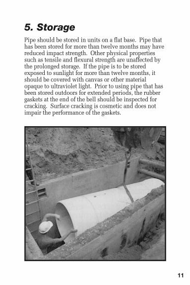
5. Storage Pipe should be stored in units on a flat base. Pipe thathas been stored for more than twelve months may havereduced impact strength. Other physical propertiessuch as tensile and flexural strength are unaffected bythe prolonged storage. If the pipe is to be storedexposed to sunlight for more than twelve months, itshould be covered with canvas or other materialopaque to ultraviolet light. Prior to using pipe that hasbeen stored outdoors for extended periods, the rubbergaskets at the end of the bell should be inspected forcracking. Surface cracking is cosmetic and does notimpair the performance of the gaskets.

12
6. InstallationA. At the Trench SiteVylon Pipe should be handled with nylon straps ratherthan chains or cables. The pipe bedding should beprepared prior to pipe placement. If there is anydiscrepancy between the contract documents and themanufacturer’s recommended installation procedures,the engineer should be contacted and the discrepancyresolved.
B. Foundation and BeddingFoundationmaterials are based on site conditions andspecified by the project engineer in contract documentsto stabilize otherwise unstable conditions. Pipebedding is used to bring the pipe to grade and provideuniform longitudinal support. Haunchingmaterial ismost critical in controlling deflection and should beplaced so as to eliminate voids and obtain densitiesrequired in contract specifications. Care must be takento choose foundation, bedding, and haunchingmaterials that are compatible to minimize migration orloss of bedding of haunching support. Good dewateringpractices need to be followed so that embedmentmaterials can be properly placed. If earthen dams areused at any point along the line, all material toconstruct the dam needs to be removed and replacedwith the appropriate embedment material.
Figure 1TrenchTerminology

13
C. Assembly of PipeMake certain that both the bell and the spigot are clean andcontain no foreign matter including ice in cold weatherconditions that could prevent an effective seal between thegasket and the spigot surfaces. Gaskets are securely gluedin place at the factory. The gasket and interior should belubricated with the pipe lubricant specifically suited forthis purpose available from Vylon Pipe. Follow theinstructions on the lube container, making sure to clean thegasket and the spigot thoroughly. Only the gasket needs tobe lubricated around the entire circumference. Do not uselubricants that contain petroleum oils or vegetable oils, asthey may harm the gasket materials. Be careful not to letthe lubricated section touch the dirt or backfill as foreignmaterial could adhere to the surface and compromise jointintegrity. Insert the spigot into the bell entrance so that thetwo pipes are in alignment and form a straight line. Forconvenience of the manufacturing and testing process, thegasket is manufactured with an external “J-Lip”, whichextends over the end and onto the exterior surface of thepipe. This “J-Lip” does not serve any sealing function.Joint tightness is not affected by non-adhered areas alongthe “J-Lip”.The following are recommended assembly procedures:• Pulling the joint together with a nylon sling.• Blocking the bell to push the spigot “home” with a
backhoe bucket.The pipe should be assembled so that the second circularassembly mark is just visible at the edge of the bellentrance. Do not over assemble the pipe beyond thesecond assembly mark. Such overassembly could prohibitexpansion of the pipe due to temperature changes, causean obstruction as the spigot necks down into the bottom ofthe bell, or compromise joint integrity. Assembly willrequire greater effort during cold weather.

14
D. Tamping and BackfillTrench bedding shall be of uniform thickness anddensity. Once the pipe is joined together, pipeembedment material should be placed in the haunchingand pipe zone areas as called for in the projectspecifications. Uniform stable support is provided byplacing the specified material in small quantities toeliminate voids and make firm contact with the pipe.Bedding shall be placed in 6" – 8" lifts on alternate sidesof the pipe and shovel sliced if a Class I material(crushed stone). Other materials will requirecompaction in accordance with the projectspecifications. Mechanical tampers may be specified insome instances and care should be taken to avoid directcontact with the pipe. Hydrohammers should not beused within three feet on top of the pipe and only thenwhen the pipe zone material has been previouslycompacted to a minimum of 95% of Standard ProctorDensity.The initial backfill extends from the springline of thepipe to a specified height of cover above the pipe, butno less than 6 inches.Final backfill is placed over the pipe to protect it fromother objects and should be free from large rocks (morethan 3" in diameter), frozen lumps or debris. Finalbackfilling should begin after a final inspection of thetrench. Refer to Figure 1 for definition of bedding,haunches, pipe zone, initial and final backfill.For additional information, please refer to the Vylontrench detail and ASTM D2321. ASTM D2321 alsocontains useful information on how to deal withunstable or migrating soils.

15
7. Field Cutting and SealingVylon Pipe PVC sewer pipe has a uniform outsidediameter that provides a sealing surface at any pointalong its length. Open channels of the profile crosssection have been factory sealed at both the spigot andbell end to prevent water entry and facilitate air testing.Each length of the pipe has been air tested in the factoryto verify the integrity of the pipe, end seals andgasketed joints. Note that the factory spigot is formed toallow easy insertion into the bell, but that there may bea slight gap between the inner and outer wall of thisformed end. Because the seals are made in thechannels, this gap has no bearing on the sealing of thespigot end.Pipe is easier cut to length before it is placed in thetrench. A general purpose circular saw with a carbidetooth blade or a gasoline powered abrasive wheel sawworks best. Mark off the length required from thespigot or bell end with a marking pen. Do not followthe spiral barrel weld as a cutting guide. This processshould be repeated until marks are made around thecircumference of the pipe at intervals not more thantwo feet apart. A pipe wrap or straight edge can then beused to connect the marks into a continuous line forcutting.

16
NOTE:Field Sealing, as described on pages 16 and 17, is nolonger required as long as the factory bell or spigotexists on the cut piece of pipe. If both the bell andspigot are removed or if required by the projectspecifications, sealing is required and field sealing kitscan be ordered from Vylon Pipe.Field cut lengths expose the internal cell or channelstructure of Vylon Pipe. The number of exposedchannels and cartridges of epoxy needed to seal eachcut end is shown below:
Both 50 ml and 200 ml epoxy and installation kits areavailable from Vylon. The epoxy cartridges should bekept in a warm location in cold weather (heated officeor truck cab). The two part epoxy used is verytemperature sensitive and damage may occur to theapplicator or the plunger by forcing “cold” epoxythrough the mixing nozzle. However, it is also sensitiveto hot weather as well. The best temperature for theapplication of epoxy is from a minimum of 50° F to amaximum of 80° F.
No. of Cartridges, (200 ml.)Diameter Channels Needed to Seal Each End
21" - 30" 7 1.036" PS 46 6 1.036" PS 75/60 5 1.042" PS 46 5 1.542" PS 75/60 5 1.548" 4 1.554" 4 2.0

17
The following are sealing instructions:1. Clean and dry the exposed channels. Epoxy will not
cure under water or in continuously wet conditions.2. Pre-plug the Vylon Pipe channels to be sealed with
foam-rubber plugs or cotton balls. The plug materialshould be inserted at least 1-1/2" deep into thechannel.
3. Trim the tips of the mixing nozzles to maximizeflowability.
4. Attach the nozzle to the epoxy cartridge.(NOTE: Be certain the brown resins and whitecatalysts flow from the epoxy duo-pack into themixing nozzle. If the orifices under the removablecap are plugged, clear the blockage with a straightedge.)
5. Seal the channels with a solid 1-1/2" long injectionof epoxy to completely seal off the channel opening.Slowly withdraw the mixing tube while injectingthe epoxy moving the tip around to push epoxy intothe corners of each cell. It is not necessary for thesealant to be flush with the end of the pipe.
The epoxy will set tack free in 15 minutes at 75º F.Colder temperatures will prolong the required set time.The epoxy adheres easily to clean and dry Vylon Pipesurfaces.

18
8. Manhole ConnectionsManhole construction may vary regionally; however,the smooth outer wall of Vylon Pipe can be useddirectly as a sealing surface. Therefore, methods thatapply to solid wall pipe can also be used with VylonPipe.Manhole connections are generally made by one of thefollowing methods:A. Vylon Pipe manhole tee with standard Vylon Pipe
bell by spigot joint connections.B. Precast concrete manhole base with elastomeric
gasket, boot or other flexible seal sized for VylonPipe minimum outside diameter. Please refer toTable 1 in the Appendix. NOTE: The outside diameter of PS75/60 pipe islarger than PS46 pipe and the correct dimensionneeds to be provided to the manhole manufacturer.A-LOK and PRESS SEAL (PSX) Systems arecommonly used with Vylon Pipe.
C. Poured in place manhole with Vylon Pipe waterstopgasket placed firmly around the pipe. Concrete willnot bond directly to PVC. A watertight systemrequires a flexible seal or waterstop gasket betweenthe Vylon Pipe and the manhole structure.
D. Fiberglass or polyethylene manhole stubs connectedto Vylon Pipe with a properly sized flexible rubbercoupling or full circle metal coupling. Thecouplings must be sized for the minimum pipediameters.
19
The manhole foundation and bedding material shouldbe compacted to 95% Proctor Density. The pipebedding through the haunches at the manholeconnection is critical in controlling deflection at theconnection. Consult the manhole gasket manufacturerfor the maximum amount of pipe deflection the gasketsealing system can tolerate at the manhole connection.Beveling the outside surface of the Vylon Pipe beforeinserting will make the insertion process easier andhelp prevent damage to the gasket.
9. Field Service Tapsand Risers
Field service taps can be performed for all Vylon Pipediameters by using one of the following recommendedproducts.
A. Inserta Tee®
Inserta Tee is a three piece service connection that iscompression-fit into the cored wall of the Vylon Pipewall. Inserta Tee consists of a PVC hub, rubber sleeve,and stainless steel band. Inserta Tee connections areavailable for 4", 6", 8", 10" and 12" and 15" sizes. Therubber sleeve has a self-fitting/sealing insert ring that alignswith the specified Vylon Pipe diameter profile height.QwikSeal® manufactured by Fernco is a similar product.NOTE: Be sure to specify whether it is PS46 pipe orPS75/60 pipe when ordering as they have differentprofile heights.A sharp hole saw should be used to obtain a precisehole. Exposed interior channels do not have to besealed. The Inserta Tee can be installed precisely whereneeded without disturbing the bedding. Follow therecommended Inserta Tee installation instructions, butrunning the hole saw in reverse will prevent the saw teethfrom grabbing the cell ribs and will provide a cleaner cut.

20
B. Fabricated Service TeesFabricated service tees may be specified by the owneror design engineer. The fabricated tee is a one pieceunit with a reducing service tap or hub “heat fused” tothe Vylon Pipe barrel section. Fittings may be fabricatedeither from short lengths of Vylon Pipe or from solidwall pipe that has been sized to fit Vylon Pipe.NOTE: Make sure to specify whether it is for PS75/60or PS46 pipe when ordering.
C. RisersAfter the field tap is made, a vertical or angular riser isspecified to complete the service connection. Servicelines are generally 4" – 6" in diameter for single houseleads whereas industrial or multi-use laterals may belarger.Deep vertical risers generate high loads on the mainlinepipe and fitting. For vertical risers exceeding 10 ft., anouter casing pipe should be used around the riser toaccommodate the vertical settlement and frictionalforces. The casing pipe should be filled with loose filland supported above the tap with a Class I embedmentmaterial (crushed stone) pad. Please refer to the verticalriser illustration at right. Operating equipment andconcentrated loads must be kept off the vertical riseruntil a minimum 4 ft. of cover has been consolidatedabove the riser. The service lines for angular risersshould be placed against the undisturbed trench wall.

21

22
10. Tunnel Casings and GroutingAll Vylon Pipe inserted into a tunnel casing should beblocked in place or backfilled to prevent flotation whenthe pipe is under the water table. The backfill specifiedby the design engineer (coarse sand, sand-cementmixture or light-weight cellular grout) must be carefullyplaced and the pipe filled with water during thegrouting process. If grouted, the maximum groutpressure is 10 psi. Grouting pressures must be closelymonitored with a pressure gauge that is calibrated in1/10 psi graduations.
PS46 PS75/60 SLIPLINER Pipe Size Bell O.D. (in) Bell O.D. (in) Max. O.D. (in) 21" 24.54 25.10 22.68 24" 27.63 28.05 25.43 27" 31.00 31.49 28.43 30" 34.38 34.95 31.43 32" N/A N/A 34.13 36" 41.13 41.40 38.13 42" 48.50 48.30 44.38 48" 54.63 55.18 50.78 54" 61.49 62.08 57.13
A. Vylon Pipe Bell Outside DiameterMinimum Casing Pipe Sizing
The minimum size casing is that which will allow thebell to pass without interference. Alternatively, VylonSlipliner Pipe has a flush joint and may allow for asmaller casing. The table below gives the maximumbell dimension for Vylon PS46 and PS75 pipe alongwith Vylon Slipliner Pipe.
If Vylon Slipliner Pipe is used, transition pieces can beused to connect Slipliner Pipe to Direct Bury Pipe orthe transition can be made at a manhole.

23
B. Casing Spacers Vylon Pipe should not rest on the gasketed bell whilebeing pushed or pulled into the casing. Casing spacersshould be used to raise, support and place the pipelengths in the casing.Two or three spacers should be used per pipe length.Please follow the casing spacer manufacturers’recommendation.NOTE: One of the spacers must be secured to VylonPipe at the second homing mark to prevent over-belling. The others should be equally spaced along thelength of pipe.

24
C. Insertion Through the Tunnel CasingCheck with the casing spacer manufacturer’sinstallation instruction in regards to securing thespacers and as to whether or not lubrication isnecessary.Vylon Pipe can be pulled through the tunnel, assembledto previously installed joint and blocked in place. Usesteady uniform pressure to insert and assemble thejoint. Also, Vylon Pipe can be pushed through thetunnel casing using a backhoe or jacking machine in thebore pit. The maximum assembled lengths of VylonPipe to be pushed is as follows:
For greater lengths of Vylon Pipe to be pushed, usemultiple jacking pits or shorter segments that will bejoined inside the casing pipe.
Diameter Length
21" 1000 LF
24" 1000 LF
27" 750 LF
30" 750 LF
36" 500 LF
42" 500 LF
48" 400 LF
54" 400 LF
25
D. Backfilling the Annular SpaceThe need for backfilling the annular space between thecasing and Vylon Pipe carrier pipe is determined by theproject specifications. If the Vylon Pipe carrier pipewill be below ground water, Vylon Pipe should bebackfilled or blocked in place to prevent flotation. Thetunnel casing must be dewatered until after the backfillhas been placed and allowed to set up.Sand or sand-cement mixture can be blown into theannular space by using a hose or small pipe to slowlyfill the void. Make certain the void is completely filledaround the first pipe before moving on to the next.If pressure grouting is specified, please take thefollowing precautions:1. Block the Vylon Pipe in place with casing spacers.2. Fill the entire Vylon Pipe segment to be grouted
with water.3. Use a lightweight cellular grout mix or flowable fill.4. Gravity flow or pump the grout into the annular
space. Long runs may require pumping – keep thepressure less than 10 psi in the annular space. Thegrouting pressures must be closely monitored with asensitive pressure gauge with 1/10 psi graduations.

26
11. Field Testing
A. Joint IntegrityVylon Pipe joint gaskets are designed to meet therequirements of ASTM D-3212, the same jointrequirement as solid wall PVC and other gravity flowsewer pipe. The joint integrity may be tested by anexfiltration test, infiltration test, or air test. Instructionsfor a particular test procedure shall be provided by theproject engineer.
1. Air TestingAir testing must be preceding by making certain allcaps and plugs are securely blocked to preventmovement. ASTM F-1417, “Installation Acceptanceof Plastic Gravity Sewer Lines Using Low-PressureAir,” should be used as a guide. Recommended airleakage allowances for a 1.0 and 0.5 psi air pressuredrop are shown in Tables 3A and 3B in theAppendix.
2. Allowable InfiltrationAllowable infiltration shall be 25 gallons per inch ofpipe diameter per mile of length per day includingpipe and manholes. This type of test is onlyacceptable when the top of the pipe is below groundwater throughout the length of pipe being tested.
3. Allowable ExfiltrationThe allowed exfiltration for pipe and manholeconnections shall not exceed 25 gallons per inch ofdiameter per mile of length per day. Peak pressureshall not exceed 10.8 psi (25' of water) at the lowestend of the length being tested.

27
B. Deflection Testing If there is a requirement for deflection testing, bothdesigner and contractor should be aware of thefollowing recommendations:1. 7.5% is the recommended long-term deflection limit
for pipe. Both designer and owner can be assuredthat 7.5% deflection affords a 4:1 minimum safetyfactor.
2. The least expensive method of deflectionmeasurement is a Go-No Go device (mandrel). Theowner, engineer and/or contractor is responsible forsupplying the measurement device and conductingthe deflection test.
3. Table 4 in the Appendix lists the base insidediameter of Vylon Pipe and the mandrel outsidediameter for 5% (short term) and 7-1/2% (long term)deflection tests.
The contractor is responsible for locating and repairingjoints or pipe sections that fail the acceptance tests.After the repairs are made, the line shall be retested.
12. Field Repairs Vylon Pipe, if damaged before, during, or afterinstallation can often be easily repaired. Contact your Vylon Sales Representative or call Vylonat 800-382-0862 for instructions in regards to repairs.

28
Table 1. Vylon PS 46 Pipe Dimensions Nominal Nominal Nominal Y Minimum Spigot Assembly Marks Size O.D. I.D. Profile Height D1 D2
21˝ 22.11 20.75 0.680 7.75 8.75 24˝ 25.12 23.50 0.770 7.50 8.50 27˝ 28.23 26.50 0.866 8.50 9.50 30˝ 31.42 29.50 0.965 9.25 10.25 36˝ 37.80 35.50 1.150 9.00 10.00 42˝ 44.20 41.50 1.350 8.75 9.75 48˝ 50.57 47.50 1.535 10.50 11.50
54˝ 56.96 53.50 1.730 10.50 11.50
Table 2. Vylon PS75 / PS60 Pipe Dimensions Nominal Nominal Nominal Y Minimum Spigot Assembly Marks Size O.D. I.D. Profile Height D1 D2
21˝ 22.29 20.75 0.770 7.00 8.00 24˝ 25.24 23.50 0.870 7.00 8.00 27˝ 28.46 26.50 0.980 8.00 9.00 30˝ 31.69 29.50 1.095 8.25 9.25 36˝ 38.13 35.50 1.315 8.25 9.25 42˝ 44.58 41.50 1.540 8.25 9.25 48˝ 51.02 47.50 1.760 9.50 10.50
54˝ 57.47 53.50 1.985 10.50 11.50
13. Appendix of Tables

29
Table 3A. Vylon Pipe Air Leakage Allowances for Low
Pressure
Air Testing (1.0 PSIG Pressure Drop)
*Q is the allowable leakage rate in cu. ft./m
in./ft.2of inside surface area of pipe.
Pipe M
inimum
Length for Time for Specified Minimum
for Length (L)
Diameter Time Minimum
Longer Show (m
in:sec)
(in.) (min./sec.) Time (ft.) Length (sec.) 100 ft 150 ft 200 ft 250 ft 300 ft 350 ft 400 ft 450 ft
21˝
1
9:50
114
10.
470
L
19:
50
2
6:10
34:
54
4
3:37
52:
21
61:0
0
6
9:48
78:
31
24
˝
22:
40
9
9
1
3.67
4 L
2
2:47
34:
11
4
5:34
56:
58
6
8:22
79
:46
91:
10
10
2:33
27˝
2
5:30
88
17.
306
L
28:
51
4
3:16
57:
41
7
2:07
86:
32
1
00:5
7
115
:22
1
29:4
8
30
˝
28:
20
8
0
2
1.36
6 L
3
5:37
53:
25
7
1:13
89:
02
10
6:50
124
:38
1
42:2
6
160
:15
36˝
3
4:00
66
30.
768
L
51:
17
7
6:55
102:
34
12
8:12
153:
50
1
79:2
9
205
:07
2
30:4
6
42
˝
39:
48
5
7
4
1.88
3 L
6
9:48
104:
42
13
9:37
174:
30
20
9:24
244
:19
2
79:1
3
314
:07
48˝
4
5:34
50
54.
705
L
91:
10
13
6:45
182:
21
22
7:55
273:
31
3
19:0
6
364
:42
4
10:1
7
54
˝
51:
02
4
4
6
9.23
6 L
11
5:24
173:
05
23
0:47
288:
29
34
6:11
403
:53
4
61:3
4
519
:16

30
Table 3B. Vylon Pipe Air Leakage Allowances for Low
Pressure
Air Testing (0.5 PSIG Pressure Drop)
*Q is the allowable leakage rate in cu. ft./m
in./ft.2of inside surface area of pipe.
Pipe M
inimum
Length for Time for Specified Minimum
for Length (L)
Diameter Time Minimum
Longer Show (m
in:sec)
(in.) (min./sec.) Time (ft.) Length (sec.) 100 ft 150 ft 200 ft 250 ft 300 ft 350 ft 400 ft 450 ft
21˝
9:5
5
114
5.
235
L
9:5
5
1
3:05
17
:27
21:
49
26:1
1
3
0:32
34:
54
3
9:16
24˝
1
1:20
99
6
.837
L
11:
24
1
7:57
22
:48
28:
30
34:1
1
3
9:53
45:
35
5
1:17
27˝
1
2:45
88
8
.653
L
14:
25
2
1:38
28
:51
36:
04
43:1
6
5
0:30
57:
42
6
4:54
30˝
1
4:10
80
10.
683
L
17:4
8
2
6:43
35
:37
44:
31
53:2
5
6
2:19
71:
13
8
0:07
36˝
1
7:00
66
15.
384
L
25:3
9
3
8:28
51
:17
64:
06
76:5
5
8
9:44
102:
34
11
5:23
42˝
1
9:54
57
20.
942
L
34:5
4
5
2:21
69
:49
87:
15
1
04:4
2
12
2:10
139:
37
15
7:04
48˝
2
2:47
50
27.
352
L
45:3
5
6
8:23
91
:11
1
13:5
8
13
6:46
159:
33
18
2:21
205:
09
54
˝
25:
31
4
4
3
4.61
8 L
57
:42
86:
33
1
15:2
4
144
:15
173:
05
20
1:56
230:
47
25
9:38

31
Table 4. Vylon Pipe Deflection Dimensions
Out-of- Nominal Min. I.D. Roundness Base 5% 7-12%Diameter ASTM F-1803 Tolerance I.D. Deflection Deflection
21˝ 20.69˝ 0.57˝ 20.12˝ 19.11˝ 18.61˝ 24˝ 23.43˝ 0.64˝ 22.79˝ 21.65˝ 21.08˝ 27˝ 26.42˝ 0.72˝ 25.70˝ 24.41˝ 23.77˝ 30˝ 29.41˝ 0.80˝ 28.61˝ 27.18˝ 26.46˝ 36˝ 35.39˝ 0.96˝ 34.43˝ 32.71˝ 31.85˝ 42˝ 41.37˝ 1.13˝ 40.24˝ 38.23˝ 37.22˝ 48˝ 47.36˝ 1.45˝ 45.91˝ 43.61˝ 42.47˝
54˝ 53.35˝ 1.94˝ 51.41˝ 48.84˝ 47.56˝
Base I.D. = (I.D. min) - Out-of-Roundness Tolerance
Short Term: 5% Deflection = .95 (Base I.D.)Long Term: 7-12% Deflection = .925 (Base I.D.)
Note: The base inside diameters have been developed for closedprofile wall pipe manufactured in accordance with ASTM F-1803. TheOut-of-Roundness Tolerance was derived statistically from fieldmeasurement data similar to ASTM F-679.

32
Vylon is a registeredtrademark of Prime Conduit.Inserta Tee is a registeredtrademark of Inserta Fittings Co. QwikSeal is aregistered trademark ofFernco.
NOTES
Work Safely… Work with Vylon Pipe
Proudly Made In The U.S.A.www.primeconduit.com 800-382-0862
3B4 2/2015©2015 Prime Conduit, Inc.