GRAVITY SEWER MAINS & MATERIALS - Sanford, NC
35
Transcript of GRAVITY SEWER MAINS & MATERIALS - Sanford, NC

GRAVITY MAINS AND MATERIALS STANDARD SPECIFICATIONSSMGS-2
GRAVITY SEWER MAINS & MATERIALS
STANDARD SPECIFICATIONS
Scope of WorkWork performed under this contract shall consist of furnishing and installing, complete and ready for service, the sewer main with various appurtenances as shown on the contract plans and as specified.
All technical standards listed in this specification refer to the most recent version of the standard at the time of construction.
A. MATERIALS
1. Vitrified Clay Sewer Pipe - Vitrified clay sewer pipe shall be extra strengthand shall conform to ASTM C700. Joints shall be the polyester ring-typeconforming to ASTM C425.
2. Ductile Iron Pipe - All ductile iron pipe furnished for diameters four inches(4”) through sixteen inches (16”) shall be manufactured in accordance withANSI/AWWA C151/A 21.51, in eighteen-foot (18’) lengths with single rubbergasket joints in accordance with ANSI/AWWA C111/A21.11. Four-inch (4”)diameter pipe shall be Class 51 wall thickness, and six-inch (6”) throughsixteen-inch (16”) diameter pipe shall be Class 50 wall thickness inaccordance with ANSI/AWWA C150/A21.50, unless otherwise specified orshown on the plans.
a. Interior Lining: Unless otherwise specified, line all ductile iron pipeand fittings with a cement mortar lining conforming to ANSI/AWWAC104/A 21.4.
b. Exterior Coating: All ductile iron pipe shall have an outside pipecoating of bituminous material in accordance with ANSI/AWWAC151/A 21.51. Ductile iron fittings shall also be coated inaccordance with ANSI/AWWA C110/A 21.10. The final coat shallbe continuous and smooth being neither brittle when subjected tolow temperatures nor sticky when exposed to hot sun. The coatingshall adhere to the pipe at all temperatures.
c. Jointsi) Unless otherwise shown on the Drawings, pipe joints shall
be of the "push on" compression type single plain rubberSBR (styrene butadiene rubber) per ANSI/AWWA

GRAVITY MAINS AND MATERIALS STANDARD SPECIFICATIONSSMGS-3
C111/21.11, as manufactured by US Pipe, American, McWane Ductile, or approved equal.
ii) Mechanical joints shall be constructed per ANSI/AWWAC111/21.11. Bolted mechanical joints shall be used underall concrete structures and between all treatment structuresfor underground piping.
iii) Flanged joints shall be constructed of ductile iron pipeconforming to ANSI/AWWA C115/A21.15 screwed intoflanges drilled and faced per ASME/ANSI B16.1 for both 125Lb. or 250 Lb. working pressure. The pipe shall extendcompleted through the screwed-on flange. The flange faceshall be flat and perpendicular to the pipe center line.Flanged joints shall be used for all exposed (non-buried)ductile iron piping.
3. Restrained Joints for Ductile Iron Pipe and Fittings:
a. Restrained joint pipe and fittings, where called for, shall consist ofone of the following:i) Bolted retainer rings and welded retainer barsii) Boltless type which include ductile iron locking segments and
rubber retainers
b. Bolts for restrained joints, if applicable, shall conform to ASMEB18.2.1.
c. Restrained pipe and fittings shall be Flex-Ring or Lok-Ring asmanufactured by American Cast Iron Pipe Company, TR Flex or Bolt-Lok as manufactured by US Pipe, or approved equal.
4. PVC Pipe - All PVC pipe shall be manufactured in accordance with ASTMD3034 for Type PSM polyvinyl chloride (PVC) sewer pipe and fittings. AllPVC pipe shall be SDR 21 or 26 wall thickness pipe, unless otherwisespecified. PVC sewer pipe shall be used only for eight-inch (8”) diametersewer mains which will serve residential areas where further mainextensions are not possible. No commercial/industrial applications shall bepermitted.
All bell-and spigot joints shall meet ASTM D3212. All fittings shall userubber gaskets which conform to the requirements of ASTM F477.
5. Fittings - All DIP fittings shall be manufactured in accordance withANSI/AWWA C110/A21.10. Fittings shall be all bell mechanical joint perANSI/AWWA C110/A21.10 unless otherwise noted, and shall have interiorcement mortar lining in accordance with ANSI/AWWA C104/A21.4.

GRAVITY MAINS AND MATERIALS STANDARD SPECIFICATIONSSMGS-4
All PVC fittings shall be for SDR 21 or 26 wall thickness pipe, unless otherwise specified, and manufactured in accordance with ASTM D3034 for Type PSM polyvinyl chloride (PVC) sewer pipe and fittings.
6. Warning Tape - A magnetic locator tape shall be installed over any PVCpipe in the same trench one foot above the pipe. Tape shall not bemeasured separately, but included in the pipe cost.
7. Service Taps and Cleanouts - Unless otherwise specified on the Drawingsor in the Specifications, service laterals shall be constructed of 4-inchdiameter Schedule 40 PVC pipe or Thickness Class 50 DIP including thecleanout stack. PVC pipe shall comply with ASTM D1785.
All cleanout structures installed in asphalt or concrete shall be constructedwith DIP risers and fittings, a traffic-rated cast iron assembly, and corrosionresistant bronze cap. Cleanout assemblies installed in non-paved surfacesshall be either DIP (as specified above, non-traffic-rated) or PVC.
8. Pipe Connections to Existing Manholes - Connect to the existing manholeusing an integrally cast, flexible pipe boot made of Ethylene-Propylene-Diene-Monomer (EPDM). Pipe boots shall comply with ASTM C923.Finished joint shall be watertight under 30-foot head of water and shall allowfor at least 8° of deflection form the centerline of the opening in any directionwhile remaining watertight. Attach the boot using stainless steel clamps andhardware.
9. Steel Pipe - Steel pipe used as gravity sewer line, encasement pipe, or forcreek crossing installations on piers, shall meet the requirements of AWWAC200 and shall be manufactured from grade 3 steel. Steel pipe shall not beused unless indicated in the Drawings. All steel pipe, except encasementpipe, shall be 0.375” thick and shall have a clear inside diameter andthickness after applying lining as called for on the Plans. Ends of pipe shallbe beveled for butt welding. Field welding shall be done by certified weldersand shall develop the full strength of the pipe. All pipe shall behydrostatically tested to 200 psi.
The outside of buried steel pipe shall receive the recommended prime coatrecommended by the manufacturer. Over this, a multi layered, cold appliedtape wrap system which shall be shop applied and consist of a rubber andsynthetic resin primer, one (20 mils) layer of inner wrapping and two (30mils each) layer of outer wrap for a total system thickness of 80 mils. Thecold applied type wrap shall operate satisfactorily at a temperature of 150oF. The wrap shall be applied in accordance with AWWA C214 and asspecified herein. Windings shall be spiral wrapped with at least 1" ofoverlap. All fittings shall be wrapped in accordance with AWWA C209 andC214. Successive layers shall be applied such that windings are staggered

GRAVITY MAINS AND MATERIALS STANDARD SPECIFICATIONSSMGS-5
and overlay the midpoints of previous tape widths. Polyethylene backed coatings shall be protected from sunlight at all times. The wrapping shall terminate 6" from outside field weld sites. The tape wrap system shall be the YG III system as manufactured by the Polyken Division of Kendall Co., Boston MA, or equal.
The outside of exposed exterior steel pipe and fittings shall receive, over the inorganic zinc prime coat, 3 mils of modified acrylic latex which shall be Carboline 3359 as manufactured by Carboline or equal, and 1 1/2 mil top coat of modified acrylic which shall be Carboline 4685 as manufactured by Carboline, or equal.
Interior Welded Pipe: Finish wrap or heat shrink sleeves per AWWA C216 shall be applied to each joint of the pipe for continuous wrapping of all steelpiping. Weld after backfill process shall require 105 mil minimum heat shrink sleeve to be applied prior to backfilling. Backfill shall be a minimum of 3 feet over the pipe prior to welding in order to prevent excess heat from damaging the linings or sleeve.
Exterior Welded Pipe: Tape wrapping at welded joints shall be held back six inches from each end and the joints shall be field coated in accordance with AWWA Standard C209. The joint coating shall consist of a primer and two wrap layers of Polyken 934-50, Aqua-ShieldTM, or equal.
The interior of all steel pipe and fittings shall receive a cement mortar lining conforming to AWWA C602 for in-place lining, or AWWA C205 for shop lined applied lining, unless otherwise shown on the drawings. Shop lining ofwelded joint pipe shall be held back as required to facilitate welding. Inside field joints shall be prepared and lined as described by appropriated Appendices of AWWA C602 and C205.
Encasement pipe shall be spiral welded steel pipe conforming to all therequirements of ASTM A139, Grade B, with a minimum yield strength of 35,000 psi. The minimum casing and wall thickness are as follows:

GRAVITY MAINS AND MATERIALS STANDARD SPECIFICATIONSSMGS-6
Carrier Pipe & Casing SizeCarrier Pipe Railroad Casing Road Casing
Nominal Size O.D. O.D. Thickness O.D. Thickness
4 4.80 12.75 0.250 12.75 0.1886 6.90 12.75 0.250 12.75 0.1888 9.05 16.00 0.281 16.00 0.25010 11.10 18.00 0.312 18.00 0.25012 13.20 20.00 0.344 20.00 0.25014 15.30 24.00 0.375 24.00 0.25016 17.40 30.00 0.469 30.00 0.31218 19.50 30.00 0.469 30.00 0.31220 21.60 30.00 0.469 30.00 0.31224 25.80 36.00 0.532 36.00 0.37530 32.00 42.00 0.625 42.00 0.50036 38.30 48.00 0.688 48.00 0.50042 44.50 54.00 0.781 54.00 0.500
10. Pre-Cast Concrete Manholes - Pre-cast reinforced concrete manholes shall be used in lieu of concrete block manholes unless otherwise specified.
a. Stone base shall be a minimum of 6” thick compacted #67 stone and shall be 6” wider than the manhole base on all sides.
b. 4’-0 inside diameter barrel unless otherwise noted.
c. Monolithic base slab and lower barrel section.
d. Eccentric cone section with a height of between two feet (2’) and four feet (4’).
e. 2’-0 inside diameter top section with height not to exceed twenty-four inches (24”).
f. Precast reinforced concrete grade adjustment ring.
g. Standard manhole ring and cover shall conform with AASHTO H-20loadings. Cover shall be stamped “SEWER”.
h. Frames shall be grouted in place. Frames that are above grade shall be anchored in place with anchor bolts.
i. Equally spaced, slip-resistant, plastic-coated cast iron manhole steps not to exceed sixteen inches (16”) c/c. Steps shall have a

GRAVITY MAINS AND MATERIALS STANDARD SPECIFICATIONSSMGS-7
minimum vertical load resistance of 400 pounds and a minimum pull out strength of 2,000 pounds when tested according to ASTM C497.
j. All joints shall be sealed with ConSeal and exterior mastic wrap meeting or exceeding ASTM C990 and ASTM C972 standards. Grout shall be applied to the interior joints, exterior joints, and lift holes, unless otherwise specified by the Engineer.
The manhole top elevations shall be set to the required elevation as indicated on the plans. Concrete grade rings or brick up to ten inches (10”) and metal rings up to three inches (3”) for a total of ten inches (10”) may be used for final grade adjustment.
The design for the reinforced concrete manhole sections shall conform to ASTM C478. The manhole sections shall have a standard tongue and groove joint. Shop drawings in accordance with the General Conditions of these Contract Documents will be required.
11. Concrete Block Manholes shall only be used when approved by Engineer.
a. Concrete Manhole Bases - shall have a 28-day compressive strength of 2500 psi and slump of not greater than four inches (4”).
b. Block Manhole Units - shall be steamed cured and shall have an individual compressive strength of 2500 psi of the cross-sectional area of the unit as laid up in the wall. The maximum average absorption shall not exceed 7% by weight nor exceed 8% by weight of any individual unit. Test for strength and absorption shall be made on not less than two (2), nor more than three (3), specimens consisting of whole undamaged units and based on a twenty-four (24) hour immersion test.
c. Mortar - used for sewer block masonry shall be composed of one (1) part Portland cement and two (2) parts sand. Portland cement shall meet the requirements of the latest ASTM C150, Type 1. Sand shall meet requirements of ASTM C144. Mortar shall be mixed in a clean tight mortar box or mechanical mixer, and shall be used within forty-five (45) minutes after mixing.Manhole exteriors shall be plastered with a minimum of 3/4” of an appropriate, watertight cement mortar.
d. Manholes- shall be constructed with eccentric tops, standard manhole rings and covers, and slip-resistant, plastic-coated cast-iron manhole steps equally spaced not to exceed sixteen inches (16”) c/c not more than twelve inches (12”) below rim (see detail). Steps shall

GRAVITY MAINS AND MATERIALS STANDARD SPECIFICATIONSSMGS-8
have a minimum vertical load resistance of 400 pounds and a minimum pull out strength of 2,000 pounds when tested according to ASTM C497.
Manhole block units shall be made by a manufacturer approved by the Engineer, and units shall be tested and certified.
e. Manhole castings shall be set in full mortar beds. All castings when set shall conform to the finished grade as established by the Engineer. Any castings not conforming shall be adjusted to the correct grade without extra compensation.
12. Flow Channel and Inverts
a. The flow channel straight through a manhole shall be made to conform as closely as possible in shape and slope to that of the connecting sewers. The channel walls shall be formed or shaped to three quarters (3/4) of the height of the crown of the outlet sewer in such a manner to not obstruct maintenance, inspection, or flow in the sewers.
b. Inverts in all manholes shall be shaped to form a smooth and regular surface, free from sharp or jagged edges. Changes in direction of flow shall be made with a smooth curve. They shall be sloped adequately to prevent sedimentation.
c. When curved flow channels are specified in manholes, including branch inlets, minimum slopes should be increased to maintain acceptable velocities.
d. A bench shall be provided on each side of any manhole channel when the pipe diameter(s) are less than the manhole diameter. The bench shall be sloped no less than 1/2 inch per foot (4 percent). The invert elevation of any lateral sewer, service connection, or drop manhole pipe shall be above the bench surface elevation. No invert shall be located directly on the surface of the bench.
e. The bench channel may be precast concrete or brick and mortar.

GRAVITY MAINS AND MATERIALS STANDARD SPECIFICATIONSSMGS-9
13. Gravity Sewer Lines and Manholes Required to Meet Water Main Design Standards
a. Designs, materials and construction methods shall meet this Part and/or current NCDEQ standards, whichever are more stringent.
b. Manholes shall be pre-cast concrete. Manhole lift holes and grade adjustment rings shall be sealed with non-shrinking mortar or other material approved by the NCDEQ.
c. Manholes shall be constructed to be watertight per Section A. 15 of this specification.
d. Gravity sewer pipe shall be constructed of water main equivalent pipe materials, as designated on the plans, such as Class 50 DIP (if 16” or less) and SDR 21 PVC water main rated pipe. In any event Materials must meet the requirements of this Part and/or current NCDEQ standards, whichever is more stringent. Special pipe testing requirements for such purposes are listed in Section C. 5 of this specification.
14. Water Tight Manhole
a. Manhole frames and covers shall be made watertight by eliminating the vent holes, installing a rubber O-ring gasket seal or a side seal gasket, and installing either four countersunk stainless-steel hex head bolts with rubber gaskets or using a cam-loc style ring and cover.
b. Manholes noted to be water tight shall receive a watertight exterior joint seal using either butyl joint wrap or an asphalt sealant.
i) Butyl joint wrap shall be a minimum width of 12-inches and comply with ASTM C877.
ii) Asphalt sealant shall be Carboline, Bitumastic 300m; Tnemec, Tneme-Tar; or equal.
c. Manholes shall be provided with a full waterproof interior coating/lining.

GRAVITY MAINS AND MATERIALS STANDARD SPECIFICATIONSSMGS-10
i) Polyurea/polyurethane coating shall be applied in accordance with the manufacturer’s recommendation for moisture proofing the manhole.
ii) Minimum total coat shall be 100 mils. Coats can be applied by brush, spray, or roller, by a manufacturer’s certified installer.
iii) Coating shall be Duramer 1030, Sherflex Elastomeric Polyurethane, Spectra-Shield, Raven 405, or Tnemec; or equal.
d. Inlet and outlet pipes shall be joined to the manhole so as to be watertight, using a gasketed flexible rubber boot or compression type connector.
15. Suitable Backfill - No rock, boulders, stone or debris larger than four inches shall be allowed in the bedding or backfill material. Deficient or unsuitable bedding or backfill material shall be replaced or substituted with suitable bedding or backfill material. Excavated material intended for use as bedding or backfill shall not be used if exceedingly wet nor shall trenches be backfilled if flooded or excessively wet.
a. Stone: Stone used for pipe bedding and trench stabilization shall meet the gradation requirements of standard aggregate size No. 67.
b. Soil: Soils for bedding and backfill are described in the ASTM D2487 Figure 1 soils classification chart, and, for purposes of these Specifications, are grouped into five (5) categories as follows, according to their suitability:
i) Class I Soil -Angular, 6 to 40 mm (¼” to 1½“), graded stone, including a number of fill materials that have regional significance, such as coral, slag, cinders, crushed stone, andcrushed shells.
ii) Class II Soil - Coarse sands and gravels with maximum particle size of 40 mm (1½”), including variously graded sands and gravels containing small percentages of fines, generally granular and non-cohesive, either wet or dry. Soil types GW, GP, SW, and SP are included in this class.

GRAVITY MAINS AND MATERIALS STANDARD SPECIFICATIONSSMGS-11
iii) Class III Soil - Fine sand and clayey gravels, including fine sands, sand clay mixtures, and gravel clay mixtures. Soil types GM, GC, SM, and SC are included in this class.
iv) Class IV Soil Silt, silty clays, and clays, including inorganic clays and silts of medium to high plasticity and liquid limits. Soil types MH, ML, CH, and CL are included in this class. These materials are not recommended for bedding, haunching, or initial backfill.
v) Class V Soil - Includes the organic soils types OL, OH, and PT, as well as soils containing frozen earth, debris, rocks larger than 1½ inches in diameter, and other foreign materials. These materials are not recommended for bedding, haunching, or initial backfill for any of the accepted pipe materials.
Suitable soils for backfill of pipe trenches shall be Classes I – III unless otherwise specified by the Engineer. The Contractor shall be responsible for obtaining suitable backfill material if it is not available on site.
B. CONSTRUCTION METHODS
1. Trench Excavation - The Contractor shall perform all excavation of whatever substances are encountered to the depths shown on the plans or as directed by the Engineer. The width of the trench, one foot (1’) above the top of the pipe to be installed at bell end shall not exceed the outside diameter of the pipe plus twenty-four inches (24”). Where unsuitable material or rock is encountered, the trench shall be excavated six inches (6”) below the bottom of the pipe and this depth shall be refilled with suitable material and thoroughly tamped.
All excavation is unclassified. Cost of unsuitable material or rock excavation and backfill to grade shall be included in unit price bid per foot for sewer pipe, complete and in place.
When foundation material has poor supporting value, the pipe foundation shall be reinforced by one of the following methods:
a. By replacing the unsuitable material to a minimum depth of six inches (6”), or such other depth as directed by the Engineer, with gravel or crushed stone;

GRAVITY MAINS AND MATERIALS STANDARD SPECIFICATIONSSMGS-12
b. By constructing supporting cradles of Class C concrete under the pipe.
The pipe trench shall be compacted to a minimum of 12” above the top invert of the pipe. The pipe trench wall side clearance shall be a minimum of 8” and a maximum of 12” from the pipe side invert on both sides. For trenches requiring shoring and bracing, dimensions shall be taken from the inside face of the shoring and bracing. Ductile iron pipe may rest on the bottom of the pipe trench with no bedding or haunching, unless otherwise specified. PVC pipe shall be installed with a minimum 4” layer of gravel bedding underneath the pipe, with haunching from the bedding surface to half the height of the exterior pipe diameter. Over excavation will be replaced with gravel. Gravel shall be #67 or #78.
Excess excavation below grade shall be backfilled at the Contractor’s expense with suitable material, as directed by the Engineer, and thoroughly tamped. The bottom of the trench shall be shaped by hand so that the sewer will have a firm and uniform bearing.
The Contractor will, at their expense, remove by pumping or other means approved by the Engineer, any water accumulated in the trench. The Contractor shall make every effort to prevent water and other materials from entering the pipe. At the end of the day the pipe will be capped or plugged and the trench filled in if necessary.
Trench walls shall be vertical from the bottom of the trench to one foot (1’) above the top of the pipe. Above this height, sloped trench walls are permitted. The Contractor shall, at their expense, do all bracing, sheeting, and shoring necessary to perform and protect all excavations, as required for safety.
The excavation for manholes and lift station structures shall be in a vertical plane and shall be of sufficient width and depth as needed to allow proper construction.
2. General Construction Safety
a. The Contractor and any subcontractors shall be responsible for the total compliance to all federal, state, and local ordinances, laws and regulations as it relates to safe construction practices and to protecting the employees and public’s general health.
b. The Contractor shall ensure that all Occupational Safety and Health Administration (OSHA) regulations and standards are followed during all phases of the construction project.

GRAVITY MAINS AND MATERIALS STANDARD SPECIFICATIONSSMGS-13
c. The City shall not be responsible for making the Contractor adhere to OSHA regulations and standards. However, the City may report known violations or unsafe practices to the appropriate enforcement agency.
3. Bypass Pumping Plan - Where connections are to be made to existing sanitary sewer currently in operation a sewer bypass pumping plan must be submitted to the Engineer for approval prior to beginning construction activities requiring pumping operations. Pumps should be sized for 2.5 times the projected average daily flow for major outfall lines (12” and greater) and 4.5 times the projected average daily flow for all other sewer lines with a minimum of 50 gpm for the line or area of work. The Contractor shall secure pumps from a pump supplier according to the provided flow information. Pumping operations must be monitored 24 hours per day for each day of the pumping operation by qualified personnel in order to respond to problems or failures. 100% redundancy is required for pumping operations.
4. Laying Pipe - Gravity flow sewer pipe shall be laid using an approved laser under the direction of a qualified operator. The trench shall be shaped by hand to line and grade, and the bedding surface shall provide a firm foundation for the full length of the body. Grooves shall be cut in the trench for the bells so that each joint of pipe shall be bedded for its full length. Pipes shall be laid with bells up grade and ends fully and closely jointed.
All proposed gravity sewer lines shall have a maximum reach of four hundred (400) linear feet between manholes. All 8-inch gravity sewer lines shall have a slope of not less than 0.55 percent (0.55%) and not greater than 10.0 percent (10.0%). The minimum slope allowed for 6-inch sewer shall be 0.75%.
Pipe connections to new and existing manholes shall be made using a flexible pipe boot per these specifications, and in such a manner that the finished work will conform as nearly as practicable to the essential applicable requirements specified for new manholes, including all necessary concrete work, cutting, and shaping. The connection shall be centered on the manhole. Holes for the new pipe shall be of sufficient diameter to allow for the boot connection to be made but no larger than 1½ times the diameter of the pipe. Cutting the manhole shall be done in a manner that will cause the least damage to the walls, such as using a concrete core saw. Use of pneumatic hammers, chipping guns, or sledge hammers is not permitted to form new inverts. The Contractor shall prevent any construction debris from entering the existing sewer line when making the connection.

GRAVITY MAINS AND MATERIALS STANDARD SPECIFICATIONSSMGS-14
5. Backfilling - All backfill shall be made using only suitable material, as defined in these specifications. Backfill shall be placed in twelve-inch (12”) layers, loose measurement. The backfill under and around the pipe shall be hand placed on both sides simultaneously, and thoroughly compacted to prevent displacement of the pipe or disturbance of the joints. The backfill shall be brought to a point at least one foot (1’) above the top of the pipe in this manner with suitable material.
The balance of the backfill shall be placed and tamped to prevent excessive settlement in a manner satisfactory to the Engineer. If the backfill is locatedunder pavement, backfill material shall be placed in six-inch (6”) layers, loose measurement, and shall be thoroughly compacted with a mechanical tamper to a minimum 95% maximum dry density or as otherwise specified by the Engineer. The Contractor is responsible for verifying that compaction requirements have been met or exceeded by providing soils testing data from an approved geotechnical firm. Only suitable material, free from large stones or clods, shall be used and it shall be moistened, if necessary, in the opinion of the Engineer, to obtain maximum compaction.
All trash, forms, debris, and other foreign material shall be cleared from around all pipes and structures before backfilling. Backfilling around structures shall be done symmetrically and tamped as provided herein. The Contractor shall dispose of surplus materials as directed by the Engineer. The area after backfilling shall be immediately cleared of all things resulting from the work of the Contractor.
6. Water Main Crossing Sewer - Whenever it is necessary for a water main to cross over a sewer, the water main shall be laid at such an elevation that the bottom of the water main is at least eighteen inches (18”) above the top of the sewer. If local conditions prevent an eighteen-inch (18”) vertical separation, then both the water main and sewer main shall be constructed of ductile iron pipe materials with joints that are equivalent to water main standards for a distance of ten feet (10’) on each side of the crossing. Both the water main and the sewer line shall be pressure tested to assure water tightness prior to backfilling.
Whenever it is necessary for a water main to cross under a sewer, both shall be constructed of ductile iron pipe materials with joints equivalent to water main standards for a distance of ten feet (10’) on each side of the crossing. A section of water main pipe shall be centered at the crossing. Both the water main and sewer line shall be pressure tested to assure water tightness prior to backfilling.
7. Water Main Horizontal Separation – Sewer lines and water mains shall be horizontally separated by a minimum of ten feet (10’). If local conditions or

GRAVITY MAINS AND MATERIALS STANDARD SPECIFICATIONSSMGS-15
barriers prevent a 10-foot horizontal separation, then abide by one of the following:
a. The water main shall be laid in a separate trench, with the water main at least 18” above the sewer line
b. The water main shall be laid in the same trench as the sewer, with the water main located at one side on a bench of undisturbed earth, with the water main at least 18” above the sewer line
In all sections where the sewer line and the water main do not maintain the minimum 18” vertical separation, they shall be constructed according to Section B 6, Water Main Crossing Sewer.
8. Aerial Crossings
a. In cases where aerial crossings are used to cross streams, piers shall generally be located at a uniform spacing of 20 feet or 1 pier for every joint of pipe.
b. All pier footings shall be designed by a licensed NC Professional Engineer and the assumptions for the footing design included on the plans. At a minimum, the footing design shall include:
i) The allowable soil bearing capacity
ii) Design concrete compressive strength
iii) Plan for reinforcing steel with sizing and location on bars
iv) Force diagram including buoyant forces and stream velocity impacts
v) Depth of installation to prevent frost heaving and compromise from scour
vi) Bedding design to prevent differential settlement
vii) Factors of safety for unanticipated loads such as trees falling across the aerial crossing
c. Appropriate joint technology, such as flanged or restrained, adequate supports to prevent excessive flexion, or a combination of both, shall be provided for all aerial pipe crossings.

GRAVITY MAINS AND MATERIALS STANDARD SPECIFICATIONSSMGS-16
d. Precautions against freezing, such as insulation and increased slope, shall be provided. Expansion jointing shall be provided between above ground and below ground sewers. Where buried sewers change to aerial sewers, special construction techniques shall be used to minimize heaving.
9. Manhole Installation
a. Correct over-excavation with coarse aggregate, #67 or #78.
b. Remove large stones or other hard matter impeding consistent backfilling or compaction.
c. Protect manhole from damage or displacement while backfilling operation is in progress.
d. Provide clearance around sidewalls of manhole or structure for construction operations and granular backfill.
e. If ground water is encountered, prevent accumulation of water in excavations; place manhole or structure in dry trench.
f. Where possibility exists of manhole becoming buoyant in flooded excavation, anchor manhole or structure to avoid flotation as approved by the Engineer.
g. All manholes shall have a minimum drop between inverts of 0.20 feet. Manholes with an invert drop greater than 2’6” or 30” shall be required to have either an outside drop on a 4’ diameter manhole oran inside drop within a 5’ diameter manhole.
h. Precast Concrete Manholes
i) Lift precast components at lifting points designated by the manufacturer.
ii) Assemble multi-section manholes by lowering each section into excavation and seal joints with ConSeal and exterior mastic wrap pre-cast sections according to manufacturer recommendations.
iii) Lower, set level, and firmly position the base section before placing additional sections
iv) Maintain alignment between sections
GRAVITY MAINS AND MATERIALS STANDARD SPECIFICATIONSSMGS-17
v) Verify that installed manholes meet required alignment and grade
vi) Cut pipe flush with interior of structure
i. Doghouse Manholes and Structures
i) Carefully excavate around existing sewer line to adequate depth for foundation slab installation
ii) Protect existing pipe from damage
iii) Replace soft soil with granular fill compacted to 95 percent maximum density
iv) Install manhole structure around existing pipe; manhole structure shall be supported fully by compacted crushed stone bedding or a support system, as indicated on the Drawings.
v) Grout the pipe entrances so as to provide a watertight seal.
vi) Coordinate connection to existing pipe with the Owner and the Engineer.
j. Concrete Block Manholes
i) Base - Concrete masonry manholes shall be built on a slab as specified and shown on the drawings.
ii) Laying the Masonry Units - Manhole masonry units shall be laid plumb and in a full bed of mortar. A running bond will be used and the block will be laid to form a true circle (oblong or oval-shaped manholes will not be permitted unless approved by the Engineer). One (1) or two (2) courses of 2¼” high concrete brick may be used at the top of the manholes to adjust height for placing the manhole ring and cover. Concrete brick may also be used for closing openings around pipes and inverts. Buttering the manholes masonry unit on the end is not required. The cylinder which is formed when the ends of the masonry units meet must be completely filled with mortar so as to form a water-tight lock and joint. The thickness of the horizontal mortar joint will be left to the discretion of the Contractor, but shall not be less than 3/8” thick or more than 3/4” thick. The joints shall be completely filled with mortar. No spalls or bats shall be used except for shaping around irregular openings or when unavoidable to

GRAVITY MAINS AND MATERIALS STANDARD SPECIFICATIONSSMGS-18
finish out course. Competent bricklayers shall be employed on the work and all details of construction shall be in accordance with approved practices and to the satisfaction of the Engineer.
10. Service Taps and Cleanouts - All service taps shall be constructed as shown in the City of Sanford standard details. Any disturbed curbs, pavement, sidewalks, grass, etc., will be restored by the Contractor. Service laterals shall be constructed as follows:
i) Construct service connection to terminal point at right-of-way or edge of permanent easement. Terminate lateral with clean-out in accordance with details.
ii) The minimum depth of cover over piping shall be 2’.
iii) The minimum separation distance between laterals shall be 5’.
iv) The minimum residential sewer service slope shall be 2%.
v) Install a watertight plug at the termination of the service line, braced to withstand the pipeline test pressure.
Cleanout risers shall be installed by the Contractor such that the final elevation of the end of the riser pipe is a minimum of 6” above grade.
11. Wetlands
a. To prevent draining of wetlands, anti-seep collars within the gravity sewer trench shall be placed in the downstream/down gradient location of the wetland area and at least every 150 LF within the wetland area.
C. Testing
1. Deflection testing shall be performed on all PVC sewer pipe. No sooner than thirty (30) days after final backfill installation, a deflection test shall be executed on the sewer line. The maximum allowable deflection shall be five percent (5%) for PVC sewer pipes. The test shall use a nine-pronged mandrel pulled through the pipe. The contact length of the mandrel shall be at least two inches (2”). The mandrel shall be furnished by the Contractor. Mandrel needs to be sized for the pipe that is being tested. All rope, floats, or other necessary equipment necessary to perform the deflection test shall be supplied by the Contractor. Any lines not meeting this test shall be corrected by the Contractor and the test repeated.

GRAVITY MAINS AND MATERIALS STANDARD SPECIFICATIONSSMGS-19
2. Test for Displacement of Sewers - Upon completion of sewer lineconstruction, a displacement test shall be conducted by the Contractor, in the presence of the Engineer. The Contractor shall provide all labor, required confined space entry permit documents, and test apparatus. The test shall be conducted according to one or both of the two following options:1) A light will be flashed between manholes; if the illuminated interior of the pipe shows any misalignment, displaced pipe, or any other defects, they shall be corrected by the Contractor at his expense; 2) The interior of the line will be surveyed using CCTV, and the recording reviewed for any sags, misalignment, displaced pipe, or other defects; the video recording shall be submitted to the City of Sanford and the Engineer for review.
3. Infiltration Tests - Where ground water is encountered during construction, all pipe joints for the sewer line shall be of such quality that there shall be no perceptible infiltration of ground water into the sewer from any single joint. The Engineer may conduct infiltration testing if it is where deemed necessary.
The Contractor shall furnish all labor and equipment, and shall assist the Engineering in making these tests. The length of line to be tested at a time shall be subject to the approval of the Engineer. Total infiltration in one (1) twenty-four (24) hour period shall not exceed one hundred (100) gallons/inch of diameter, per mile of sewer.
4. Pressure Tests – All gravity sewer pipe required to meet water main standards based on NCDEQ requirements shall be pressure tested to water main standards of 1.5 times working pressure. This shall be based on the maximum depth of the pipe in feet within the project area times 1.5 divided by 2.31. For example, 20-foot cut x 1.5/ 2.31 = 13 psi, or NCDEQ requirements, whichever is more stringent
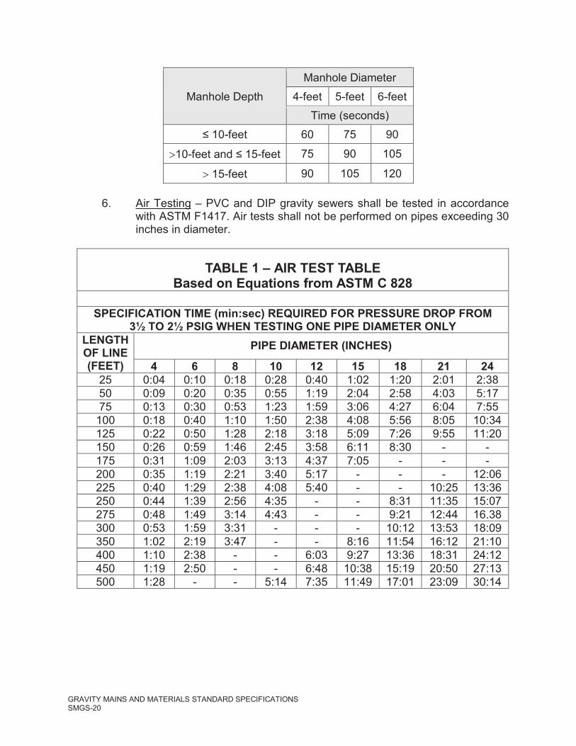
5. Vacuum Testing - All manholes shall be tested in accordance with ASTM C1244 prior to backfill. Plug pipe openings a minimum of six inches beyond the manhole wall and position the vacuum tester according to the manufacturer’s recommendations. Draw a vacuum of 10 inches of mercury, close the valve on the vacuum line and shut off the vacuum pump and measure the time for the vacuum to drop to 9 inches of mercury. The manhole shall pass when the time to drop to 9 inches of mercury meets or exceeds the table below:
GRAVITY MAINS AND MATERIALS STANDARD SPECIFICATIONSSMGS-20
Manhole DepthManhole Diameter
4-feet 5-feet 6-feetTime (seconds)
-feet 60 75 90
10- -feet 75 90 105
15-feet 90 105 120
6. Air Testing – PVC and DIP gravity sewers shall be tested in accordance with ASTM F1417. Air tests shall not be performed on pipes exceeding 30 inches in diameter.
TABLE 1 – AIR TEST TABLEBased on Equations from ASTM C 828
SPECIFICATION TIME (min:sec) REQUIRED FOR PRESSURE DROP FROM3½ TO 2½ PSIG WHEN TESTING ONE PIPE DIAMETER ONLY
LENGTH OF LINE (FEET)
PIPE DIAMETER (INCHES)
4 6 8 10 12 15 18 21 2425 0:04 0:10 0:18 0:28 0:40 1:02 1:20 2:01 2:3850 0:09 0:20 0:35 0:55 1:19 2:04 2:58 4:03 5:1775 0:13 0:30 0:53 1:23 1:59 3:06 4:27 6:04 7:55
100 0:18 0:40 1:10 1:50 2:38 4:08 5:56 8:05 10:34125 0:22 0:50 1:28 2:18 3:18 5:09 7:26 9:55 11:20150 0:26 0:59 1:46 2:45 3:58 6:11 8:30 - -175 0:31 1:09 2:03 3:13 4:37 7:05 - - -200 0:35 1:19 2:21 3:40 5:17 - - - 12:06225 0:40 1:29 2:38 4:08 5:40 - - 10:25 13:36250 0:44 1:39 2:56 4:35 - - 8:31 11:35 15:07275 0:48 1:49 3:14 4:43 - - 9:21 12:44 16.38300 0:53 1:59 3:31 - - - 10:12 13:53 18:09350 1:02 2:19 3:47 - - 8:16 11:54 16:12 21:10400 1:10 2:38 - - 6:03 9:27 13:36 18:31 24:12450 1:19 2:50 - - 6:48 10:38 15:19 20:50 27:13500 1:28 - - 5:14 7:35 11:49 17:01 23:09 30:14

GRAVITY MAINS AND MATERIALS STANDARD SPECIFICATIONSSMGS-21
7. Protection of Construction – When and where deemed appropriate by MUTCD or OSHA standards, the Contractor shall provide and maintain warning signs, lights, flagmen, and barricades at his own expense and cost, and shall take all necessary precautions to adequately protect life and property.
D. METHOD OF MEASUREMENT
1. Sewer Pipe – Measurement of sewer pipe shall include the total linear feet of pipe installed, complete, in place, tested, and accepted by City or Engineer, including the trenching, backfilling, clear and grubbing right-of-ways, furnishing labor tools, materials and equipment necessary for installing pipe, and for backfilling and all other necessary incidentals. Depth shall be measured from the existing ground surface to the bottom of the pipe.
2. Manholes - For manholes, by actual count at the various depths stated in the proposal, depth shall be measured from the top of manhole casting to the invert.
3. Service Taps - Taps will be counted by unit, complete in place, and accepted including the restoration of pavement, curb, gutter, sidewalks, grass, etc.
E. BASIS OF PAYMENT
Payment will be made for all items based on the unit and lump sum prices stated in the proposal and measured as previously described. Any costs for cleanup and seeding shall be included in the price per linear foot for installation of the sewer line. Construction of the sewer line shall be considered as ninety percent (90%) complete until such time as the cleanup for that section of line is completed to the satisfaction of the City. Therefore, payment shall only be ninety percent (90%) of the price per linear foot until the cleanup, seeding, etc., for that section of line is completed to the City’s satisfaction. The prices stated in the proposal shall cover all work required to properly install the sewer mains, complete with all necessary appurtenances, in accordance with the plans and specifications.
GRAVITY MAINS AND MATERIALS STANDARD SPECIFICATIONSSMGS-22
F. ENGINEERING
All proposed gravity sewer lines shall be submitted to the City of Sanford for review and approval. All plans shall include plan and profile views and the signature of a registered P.E.
BORING AND JACKING ADDITIONAL INFORMATION
Scope of Work
1. Furnish all labor, equipment, materials, and incidentals necessary for installing encasement pipe and carrier pipes under highways, railroads, streets, or other locations by the bore and jack method as specified herein.
2. Perform construction in a manner that will not interfere with the operation of any street, highway, railway, or other facility, and will not weaken or damage the roadbed or structure. Furnish and maintain barricades and lights to safeguard traffic and pedestrians as required by authorities having jurisdiction until such time as the operation has been completed. It is the contractor’s responsibility to provide and maintain any and all devices necessary to ensure the safety of employees, pedestrians, and the general public at all times until full project completion.
3. The omission from the Drawings and Specifications of any details required for the satisfactory installation of the work in its entirety shall not relieve the CONTRACTOR of full responsibility for providing such necessary items.
Section Includes
1. Casing and jacking pipe.
2. Excavation for approach trenches and pits.
REFERENCE STANDARDS
A. American Association of State Highway and Transportation Officials:
1. AASHTO HB-17 - Standard Specifications for Highway Bridges.
B. American Railway Engineering and Maintenance-of-Way Association:
1. AREMA - Manual for Railway Engineering.

GRAVITY MAINS AND MATERIALS STANDARD SPECIFICATIONSSMGS-23
C. American Welding Society:
1. AWS D1.1 - Structural Welding Code – Steel.
D. ASTM International:
1. ASTM A36 - Standard Specification for Carbon Structural Steel.
2. ASTM A139 - Standard Specification for Electric-Fusion (Arc)-Welded Steel Pipe (NPS 4 and Over)
3. ASTM C33 - Standard Specification for Concrete Aggregates.
4. ASTM C150 - Standard Specification for Portland Cement.
E. National Utility Contractors Association:
1. NUCA - Guide to Pipe Jacking and Microtunneling Design.
F. State of North Carolina Department of Transportation
1. Standard Specifications for Roads and Structures, latest revision
2. Policies and Procedures for Accommodating Utilities on Highway Rights of Way
G. Occupational Safety and Health Administration
1. Safety and Health Regulations for Construction
COORDINATION
A. For all work within the Department of Transportation right-of-way, notify the appropriate office of the Department of Transportation at least 72 hours prior to beginning construction.
B. No blasting will be done without prior written approval of the Department of Transportation. If requested, furnish the Department of Transportation with details of the proposed blasting method.
C. At all times, ensure the free and unobstructed use of the right-of-way for the passage of traffic without delay or danger to life, equipment, or property.
PREINSTALLATION MEETINGS

GRAVITY MAINS AND MATERIALS STANDARD SPECIFICATIONSSMGS-24
A. All parties, including the OWNER, ENGINEER, CONTRACTOR, installer, any subs and the product manufacturer, shall meet prior to any work is started to review the specification and discuss job specific expectations, needs and requirements.
SUBMITTALS
A. Product Data: Submit product data on steel casing pipe, casing spacers, and end seal materials.
B. Shop Drawings:1. Indicate details of casing, jacking head, sheeting, and other falsework for trenches
and pits, and support for excavation, field sketches, and other details to complete Work.
2. Indicate relationship of proposed installation to existing facilities and/or natural features over installation, angle of installation, right-of-way lines, and general layout of built facilities.
3. Indicate cross-section(s) from field survey, showing installation in relation to actual profile of ground.
4. Submit description of proposed construction plan, dewatering plan, and plan to establish and maintain vertical and horizontal alignments.
C. Delegated Design Submittals: Submit signed and sealed Shop Drawings with design calculations and assumptions for shoring and bracing.
D. Submit emergency response procedures to handle situations when conduit is compromised and jeopardizes safety or integrity of installation.
1. If any movement or settlement occurs which causes or might cause damage to existing facilities or structures over, along, or adjacent to the work, immediately stop any and all work except that which assists making the work secure and prevents further movement, settlement, or damage. Resume installation activities only after all necessary precautions have been taken to prevent further movement, settlement or damage, and repair the damage, at no additional cost to the OWNER, to the satisfaction of the ENGINEER.
E. Submit written report results of visual check of entire length of casing prior to installation of carrier to verify that there are no voids or defective joints.
F. Qualifications Statements:
1. Submit qualifications for installer and licensed professional.
2. Welders: Qualify procedures and personnel according to AWS D1.1.

GRAVITY MAINS AND MATERIALS STANDARD SPECIFICATIONSSMGS-25
CLOSEOUT SUBMITTALS
A. Project Record Documents: Record actual locations of casing, carrier pipe, and invert elevations.
B. Identify and describe unexpected variations to subsoil conditions or discovery of uncharted utilities.
QUALITY ASSURANCE
A. Perform Work according to AREMA, NUCA, OSHA, and AASHTO guidelines.
B. Comply with all Federal, State, and local laws, ordinances, rules, and regulations affecting the work under this section.
C. Where applicable, perform Work according to State of North Carolina Department of Transportation standards.
D. All welding procedures used to fabricate and install steel casings shall be performed in accordance the provisions of ANSI/AWS D1.1.
QUALIFICATIONS
A. Installer: Company specializing in performing Work of this Section with minimum five years' documented experience.
B. Welders: AWS qualified by an independent local, approved testing agency within previous 12 months for employed weld types.
1. A minimum of 3 years recent experience within the last 5 years with welding procedures required on this project.
C. Licensed Professional: Professional ENGINEER experienced in design of specified Work and licensed in State of North Carolina.
DELIVERY, STORAGE, AND HANDLING
A. Inspection: Accept materials on Site in manufacturer's original packaging and inspect for damage. If any defective material is discovered, remove it and replace with sound pipe or repair defective material in an approved manner and at the CONTRACTOR’s expense.
B. Handling: Support casing and carrier pipes with nylon slings during handling. Do not place pipe within pipe of a larger size and do not roll or drag pipe over gravel or rock.

GRAVITY MAINS AND MATERIALS STANDARD SPECIFICATIONSSMGS-26
C. Storage:
1. Store products according to manufacturer instructions.
2. Use wooden shipping braces between layers of stacked pipe.
3. Stack piping lengths no more than three layers high.
4. Store field joint materials in original shipping containers.
5. Do not store any plastic materials in direct sunlight.
D. Protection:
1. Protect materials from moisture and dust by storing in clean, dry location remote from construction operations areas.
2. Provide temporary end caps and closures on piping and fittings and maintain in place until installation.
3. Protect piping system pieces from entry of foreign materials and water by installing temporary covers, completing sections of Work, and isolating parts of completed system.
4. Provide additional protection according to manufacturer instructions.
E. When any material is damaged during transporting, unloading, handling or storing, the undamaged portions may be used as needed, or, if damaged sufficiently, the ENGINEER will reject the material as being unfit for installation.
AMBIENT CONDITIONS
A. Storage Temperature: Maintain 60 to 85 degrees F.
WARRANTY
A. All materials shall be warranted to be free from defects in workmanship and materials for one (1) year following final acceptance by the OWNER.
EXISTING CONDITIONS
A. Field Measurements:
1. Verify field measurements prior to fabrication.
2. Indicate field measurements on Shop Drawings.

GRAVITY MAINS AND MATERIALS STANDARD SPECIFICATIONSSMGS-27
CASING AND JACKING PIPE
A. Steel Casing Pipe:
1. Comply with ASTM A139, Grade B.
2. Minimum Yield Strength: 35,000 psi.
3. Welded Joints:
a. Comply with AWS D1.1.
b. Full circumference.
4. Interior and exterior coating.
a. Additional coating requirements, if any, may be included in the encroachment agreement. The encroachment agreement is included and made a part of the Contract Documents.
5. Pipe Sizing:
a. The encasement pipe shall be of the diameter and wall thickness indicated on the drawings, but in no case shall they be less than required by authorities having jurisdiction.
B. Performance and Design Criteria:
1. Casing Pipe: Leakproof.
2. Loading:
a. Highways:
1) Earth cover.
2) H-20 live loading, according to AASHTO HB-17.
3) Impact loading according to AASHTO HB-17.b. Railways:
1) Earth cover.
2) Comply with AREMA - Manual for Railway Engineering.
3) Impact loading according to AREMA guidelines.
GRAVITY MAINS AND MATERIALS STANDARD SPECIFICATIONSSMGS-28
3. Bracing, Backstops, and Jacks: Of sufficient rating for continuous jacking without stopping except to add pipe sections, and to minimize tendency of ground material to freeze around casing pipe.
CARRIER PIPE
A. Site Water Distribution System Piping: As specified.
B. Sanitary Sewage System Piping: As specified.
MATERIALS
A. Soil Backfill for Trench Approaches and Pits to Finish Grade: Subsoil with no rocks 6 inches in diameter or greater, frozen earth, or foreign matter.
B. Filling and Sealing Grout at Pipe Ends: Grout shall be a mixture of approximately one part cement, 1-1/2 parts sand, water reducing retarder and sufficient water to make a stiff workable mix.
C. Pressure-Grout Mix: One part portland cement and two parts mortar sand, mixed with water to consistency applicable for pressure grouting.
D. Mortar Sand: Comply with ASTM C33.
E. Portland Cement:1. Portland cement shall be ASTM C150 Type II or Type V, containing less than 0.6
percent alkali.
ACCESSORIES
A. Steel and Plastic Supports and Insulators:
1. Bands: 14-gage stainless steel.
2. Flange Bolts: 5/16-inch stainless steel.
3. Liner: Heavy-duty PVC.
4. Skids: UHMW Polyethylene.
a. Wood skids are not an acceptable method of supporting the carrier pipe.
5. For Carrier Pipes up to 36 Inches in Diameter Conveying Water or Wastewater

GRAVITY MAINS AND MATERIALS STANDARD SPECIFICATIONSSMGS-29
a. Casing spacers shall be spaced a maximum of eight (8) feet apart along the length of the carrier pipe with one casing spacer within two (2) feet of each side of a pipe joint and the rest evenly spaced.
b. The casing spacer polymer shall contain ultraviolet inhibitors and shall have a minimum compressive strength of 3,000 psi, an 800 Volts/mil dielectric strength and impact strength of 1.5 ft-lbs/inch. Each casing spacer shall have full length, integrally molded skids extending beyond the bell or mechanical joint of the carrier pipe.
B. Steel Strapping: Comply with ASTM A36.
C. Casing End Seals
1. Casing end seals shall be used to completely close both openings on either side of the casing.
2. End seals shall be 1/8-inch thick synthetic rubber secured with stainless steel banding straps. Other end seals may be constructed only as pre-approved by the ENGINEER or as required by authorities having jurisdiction.
EXAMINATION
A. Verify that connection to existing piping system, sizes, locations, and invert elevations are as indicated on Drawings.
B. Examine the areas and conditions under which the boring is to be installed and become familiar with the conditions under which the work will be performed, all necessary details, and the suitability of the proposed equipment and methods for the orderly prosecution of the work.
C. Do not proceed with the work until unsatisfactory conditions have been corrected in an acceptable manner.
D. Notify the ENGINEER immediately if conditions do not permit a bore and jack installation.
PREPARATION
A. Identify required lines, levels, contours, and datum locations.
B. Existing Utilities:
1. Locate and identify utilities indicated to remain and protect from damage.
2. Notify ENGINEER of any potential utility conflicts immediately.

GRAVITY MAINS AND MATERIALS STANDARD SPECIFICATIONSSMGS-30
3. Establish minimum separation of proposed installation from existing utilities according to authorities having jurisdiction.
C. Maintain access to existing facilities and other active installations requiring access.
D. Furnish, install and remove, to the extent required, thrust blocks or whatever provisions may be required for driving the casings/sleeves and pipes forward.
INSTALLATION
A. Safety:
1. Provide all necessary bracing, bulkheads, and/or shields to ensure complete safety to all traffic at all times during the progress of the work, and perform the work in such a manner as to not interfere with normal traffic over the work.
B. Dewatering:
1. Intercept and divert surface drainage precipitation and ground water away from excavation through use of dikes, curb walls, ditches, pipes, sumps, or other methods.
2. Develop substantially dry subgrade for subsequent operations.
3. Comply with requirements of local and state authorities for dewatering to any watercourse, prevention of stream degradation, and erosion and sediment control.
4. Keep all excavations free from ground and surface water during the operation and be prepared to implement groundwater control on short notice as directed by the ENGINEER, even if observed water levels prior to construction are below the invert elevation of the casing pipe.
C. Pits or Approach Trenches:
1. Suitable pits or trenches shall be excavated for the purpose of jacking operations and for placing the end joints of pipe.
2. All excavations shall be protected with suitable fencing or barricades to prohibit unauthorized access to the work site.
3. Excavate approach trenches or pits as Site conditions require.
4. Ensure that casing entrance faces as near perpendicular in alignment as conditions permit.
5. Establish vertical entrance face at least 1 foot above top of casing.

GRAVITY MAINS AND MATERIALS STANDARD SPECIFICATIONSSMGS-31
6. Where necessary, trenches shall be securely sheeted and braced to prevent caving.
7. The pits or trenches shall be backfilled immediately after the operation has been completed.
D. Casing Pipe:
1. The driven portions of the casing shall be advanced from the lower end of the casing unless specific permission to do otherwise is obtained from the ENGINEER.
2. Boring:
a. Boring operations shall be continuous to their completion, and unnecessary or prolonged stoppages shall not be allowed to prevent the pipe from becoming firmly set in the embankment.
b. Steel rails or beams embedded in concrete shall be used in the pit for placement and alignment of each piece of casing during installation operations.
c. Push pipe into ground with boring auger rotating within pipe to remove soil.
d. Do not advance cutting head ahead of casing pipe, except for distancenecessary to permit cutting teeth to maintain clearance for pipe.
e. Arrange machine bore and cutting head to be removable from within pipe.
f. Arrange face of cutting head to provide barrier to free flow of soft material.
g. If unstable soil is encountered during boring, retract cutting head into casing to permit balance between pushing pressure and ratio of pipe advancement to quantity of soil.
3. Abandonment of Bore: In the event that an obstruction is encountered during the dry boring operation, the casing shall be inspected by the ENGINEER and determined if it may be removed or left in place.
a. If an obstruction is encountered during the dry bore operation which prohibits further extending of the bore, terminate the bore if approved by ENGINEER as follows:
1) Remove the boring auger and the casing pipe.
GRAVITY MAINS AND MATERIALS STANDARD SPECIFICATIONSSMGS-32
2) Fill the void created by the removal of the pipe with grout as specified at a minimum pressure of 25 pounds per square inch.
3) Provide suitable temporary forms to retain the grout within the limits of the former casing pipe.
4) Remove forms after the grout has set.
5) Move to another bore site as directed by the ENGINEER.
4. Jacking:
a. The pipe to be jacked shall be set on guides, braced together, to properly support the section of the pipe and direct it to the proper line and grade.
b. Construct adequate thrust wall normal to proposed line of thrust.
c. Impart thrust load to pipe through suitable thrust ring sufficiently rigid to ensure uniform distribution of thrust load on full pipe circumference.
d. Remove any pipe damaged in boring and jacking operations and replace at no additional cost to the OWNER.
5. Pressure Grouting: If voids in excess of 3-inch are encountered, install grout holes of a size suitable for injecting grout between casing pipe and surrounding earth.
a. The grouting operation shall take place immediately after completion of the bore.
b. Grout holes shall be installed at intervals not exceeding 10-feet.
c. Inject grout into the void under sufficient pressure to prevent settlement.
d. No additional compensation will be paid for grouting.
E. Carrier Pipe:
1. Clean, inspect, and handle pipe as specified.
2. Prevent damage to pipe joints as carrier pipe is placed in casing.
3. Supports:
a. Support pipeline within casing using skids or rollers such that no external loads are transmitted to carrier pipe.
b. Attach supports to barrel of carrier pipe; do not rest carrier pipe on bells.

GRAVITY MAINS AND MATERIALS STANDARD SPECIFICATIONSSMGS-33
c. No blocks or spacers shall be wedged between the carrier pipe and the top of the casing.
4. The carrier pipe shall extend a minimum of 2 feet past casing pipe on each end.
5. Install an end seal on each end of the casing pipe so that annular space between the casing and carrier pipe is sealed.
TOLERANCES
A. Excavation:
1. Minimize overbore by matching the cutter diameter to the diameter of the encasement pipe as closely as practicable. Do not overcut excavation by more than 1 inch greater than OD of casing pipe.
B. The alignment and grade of the encasement pipe shall be carefully maintained and the encasement pipe installed in a manner that will allow of the installation of the carrier pipe to the lines and grades shown on the plans.
C. Casing Pipe Vertical and Horizontal Alignment:
1. Horizontal: Variation in the final position of the pipe from the line and grade established by the ENGINEER will be permitted only to the extent of 0.5% in lateral alignment.
2. Vertical Alignment: Where the carrier pipe is to be laid on a uniform grade (i.e. gravity sewer line or gravity storm drain) the variation in vertical alignment will be as follows:

GRAVITY MAINS AND MATERIALS STANDARD SPECIFICATIONSSMGS-34
Carrier Pipe Size
% Grade Tolerance
8 ±0.0410 ±0.02812 ±0.02214 ±0.01715 ±0.01516 ±0.01418 ±0.01220 ±0.0121 ±0.0124 ±0.00827 ±0.006730 ±0.005833 ±0.005236 ±0.0046
3. In no instance shall the grade of the carrier pipe be less than the minimum grade required by OWNER or State Regulations.
D. Pipe Bells: Minimum 1/2-inch clearance to casing.
FIELD QUALITY CONTROL
A. Manufacturer Services: Furnish services of manufacturer's representative experienced in use of equipment and installation of products furnished under this Section as necessary to ensure compliance with the requirements of this Section throughout the course of the work.
CLEANING
A. Remove temporary facilities for casing installation and jacking operations.
B. Repair all damage and restore the property to its original condition.
PROTECTION
A. Protect plant life, lawns, rock outcroppings, and other features of final landscaping.

GRAVITY MAINS AND MATERIALS STANDARD SPECIFICATIONSSMGS-35
B. Protect bench marks, survey control points, existing structures, fences, sidewalks, paving, and curbs from excavating equipment and vehicular traffic.
END OF SECTION