PV Inverter SUNNY MINI CENTRAL 4600A / 5000A /...
84
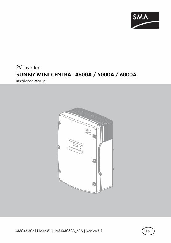
SMC46-60A11-IA-en-81 | IME-SMC50A_60A | Version 8.1 EN PV Inverter SUNNY MINI CENTRAL 4600A / 5000A / 6000A Installation Manual
Transcript of PV Inverter SUNNY MINI CENTRAL 4600A / 5000A /...
SMC46-60A11-IA-en-81 | IME-SMC50A_60A | Version 8.1 EN
PV InverterSUNNY MINI CENTRAL 4600A / 5000A / 6000AInstallation Manual


SMA Solar Technology AG Table of Contents
Installation Manual SMC46-60A11-IA-en-81 3
Table of Contents1 Information on this Manual. . . . . . . . . . . . . . . . . . . . . . . . . 71.1 Validity . . . . . . . . . . . . . . . . . . . . . . . . . . . . . . . . . . . . . . . . . . . . 71.2 Target Group . . . . . . . . . . . . . . . . . . . . . . . . . . . . . . . . . . . . . . . 71.3 Additional Information . . . . . . . . . . . . . . . . . . . . . . . . . . . . . . . . 71.4 Symbols Used . . . . . . . . . . . . . . . . . . . . . . . . . . . . . . . . . . . . . . . 82 Safety . . . . . . . . . . . . . . . . . . . . . . . . . . . . . . . . . . . . . . . . . . 92.1 Intended Use. . . . . . . . . . . . . . . . . . . . . . . . . . . . . . . . . . . . . . . . 92.2 Safety Precautions. . . . . . . . . . . . . . . . . . . . . . . . . . . . . . . . . . . 102.3 Explanation of Symbols . . . . . . . . . . . . . . . . . . . . . . . . . . . . . . 112.3.1 Symbols on the Inverter. . . . . . . . . . . . . . . . . . . . . . . . . . . . . . . . . . . . . . . . . 112.3.2 Symbols on the Type Label . . . . . . . . . . . . . . . . . . . . . . . . . . . . . . . . . . . . . . 12
3 Unpacking. . . . . . . . . . . . . . . . . . . . . . . . . . . . . . . . . . . . . . 133.1 Scope of Delivery . . . . . . . . . . . . . . . . . . . . . . . . . . . . . . . . . . . 133.2 Identifying the Inverter . . . . . . . . . . . . . . . . . . . . . . . . . . . . . . . 144 Assembly. . . . . . . . . . . . . . . . . . . . . . . . . . . . . . . . . . . . . . . 154.1 Safety . . . . . . . . . . . . . . . . . . . . . . . . . . . . . . . . . . . . . . . . . . . . 154.2 Selecting the Mounting Location. . . . . . . . . . . . . . . . . . . . . . . . 154.3 Mounting the Inverter using the Wall Mounting Bracket . . . . . 175 Electrical Connection . . . . . . . . . . . . . . . . . . . . . . . . . . . . . 205.1 Overview of the Connection Area . . . . . . . . . . . . . . . . . . . . . . 205.1.1 Exterior View . . . . . . . . . . . . . . . . . . . . . . . . . . . . . . . . . . . . . . . . . . . . . . . . . 205.1.2 Interior View . . . . . . . . . . . . . . . . . . . . . . . . . . . . . . . . . . . . . . . . . . . . . . . . . 215.2 Connection to the Electricity Grid (AC). . . . . . . . . . . . . . . . . . . 225.2.1 Conditions for the AC Connection . . . . . . . . . . . . . . . . . . . . . . . . . . . . . . . . 225.2.2 Connecting the Inverter to the Electricity Grid (AC) . . . . . . . . . . . . . . . . . . . 245.2.3 Additional Earthing of the Enclosure . . . . . . . . . . . . . . . . . . . . . . . . . . . . . . . 25

Table of Contents SMA Solar Technology AG
4 SMC46-60A11-IA-en-81 Installation Manual
5.3 Setting the Display Language . . . . . . . . . . . . . . . . . . . . . . . . . . 265.4 Connecting the PV Array (DC) . . . . . . . . . . . . . . . . . . . . . . . . . 275.4.1 Conditions for DC Connection . . . . . . . . . . . . . . . . . . . . . . . . . . . . . . . . . . . 275.4.2 Assembling the DC Connectors. . . . . . . . . . . . . . . . . . . . . . . . . . . . . . . . . . . 285.4.3 Opening the DC Connector . . . . . . . . . . . . . . . . . . . . . . . . . . . . . . . . . . . . . 305.4.4 Connecting the PV Array (DC) . . . . . . . . . . . . . . . . . . . . . . . . . . . . . . . . . . . 315.5 Connecting the SMA Power Balancer . . . . . . . . . . . . . . . . . . . 345.5.1 Configuration . . . . . . . . . . . . . . . . . . . . . . . . . . . . . . . . . . . . . . . . . . . . . . . . 345.5.2 Cabling . . . . . . . . . . . . . . . . . . . . . . . . . . . . . . . . . . . . . . . . . . . . . . . . . . . . . 385.5.3 Function Test . . . . . . . . . . . . . . . . . . . . . . . . . . . . . . . . . . . . . . . . . . . . . . . . . 415.6 Communication . . . . . . . . . . . . . . . . . . . . . . . . . . . . . . . . . . . . . 425.7 Setting the Grid and Country Parameters . . . . . . . . . . . . . . . . . 425.7.1 Setting the Installation Country . . . . . . . . . . . . . . . . . . . . . . . . . . . . . . . . . . . 425.7.2 Setting the Stand-Alone Grid Operation . . . . . . . . . . . . . . . . . . . . . . . . . . . . 435.7.3 Additional Country Parameters . . . . . . . . . . . . . . . . . . . . . . . . . . . . . . . . . . . 43
6 Commissioning . . . . . . . . . . . . . . . . . . . . . . . . . . . . . . . . . . 446.1 Commissioning the Inverter . . . . . . . . . . . . . . . . . . . . . . . . . . . . 446.2 Only for Italy: Self-Test in Accordance with CEI 0-21. . . . . . . . 456.2.1 Starting the Self-Test . . . . . . . . . . . . . . . . . . . . . . . . . . . . . . . . . . . . . . . . . . . 456.2.2 Abortion of the Self-Test . . . . . . . . . . . . . . . . . . . . . . . . . . . . . . . . . . . . . . . . 466.2.3 Restarting the Self-Test. . . . . . . . . . . . . . . . . . . . . . . . . . . . . . . . . . . . . . . . . . 466.3 Display Messages During the Start-up Phase . . . . . . . . . . . . . . 477 Opening and Closing. . . . . . . . . . . . . . . . . . . . . . . . . . . . . 487.1 Safety . . . . . . . . . . . . . . . . . . . . . . . . . . . . . . . . . . . . . . . . . . . . 487.2 Opening the Inverter. . . . . . . . . . . . . . . . . . . . . . . . . . . . . . . . . 487.3 Closing the Inverter . . . . . . . . . . . . . . . . . . . . . . . . . . . . . . . . . . 518 Maintenance and Cleaning . . . . . . . . . . . . . . . . . . . . . . . . 538.1 Cleaning the Inverter. . . . . . . . . . . . . . . . . . . . . . . . . . . . . . . . . 538.2 Checking Heat Dissipation . . . . . . . . . . . . . . . . . . . . . . . . . . . . 53

SMA Solar Technology AG Table of Contents
Installation Manual SMC46-60A11-IA-en-81 5
8.2.1 Cleaning the Fans . . . . . . . . . . . . . . . . . . . . . . . . . . . . . . . . . . . . . . . . . . . . . 538.2.2 Checking the Fans. . . . . . . . . . . . . . . . . . . . . . . . . . . . . . . . . . . . . . . . . . . . . 558.2.3 Cleaning the Ventilation Grids . . . . . . . . . . . . . . . . . . . . . . . . . . . . . . . . . . . 568.3 Checking the Electronic Solar Switch (ESS) for Wear . . . . . . . 579 Troubleshooting . . . . . . . . . . . . . . . . . . . . . . . . . . . . . . . . . 589.1 Blink Codes. . . . . . . . . . . . . . . . . . . . . . . . . . . . . . . . . . . . . . . . 589.2 Error Messages. . . . . . . . . . . . . . . . . . . . . . . . . . . . . . . . . . . . . 599.3 Red LED is Permanently Glowing . . . . . . . . . . . . . . . . . . . . . . . 639.3.1 Checking the PV Array for Earth Faults . . . . . . . . . . . . . . . . . . . . . . . . . . . . . 649.3.2 Checking the Function of the Varistors . . . . . . . . . . . . . . . . . . . . . . . . . . . . . 66
10 Decommissioning . . . . . . . . . . . . . . . . . . . . . . . . . . . . . . . . 6810.1 Dismounting the Inverter . . . . . . . . . . . . . . . . . . . . . . . . . . . . . . 6810.2 Packing the Inverter. . . . . . . . . . . . . . . . . . . . . . . . . . . . . . . . . . 6910.3 Storing the Inverter . . . . . . . . . . . . . . . . . . . . . . . . . . . . . . . . . . 6910.4 Disposing of the Inverter . . . . . . . . . . . . . . . . . . . . . . . . . . . . . . 6911 Technical Data . . . . . . . . . . . . . . . . . . . . . . . . . . . . . . . . . . 7011.1 DC/AC . . . . . . . . . . . . . . . . . . . . . . . . . . . . . . . . . . . . . . . . . . . 7011.1.1 Sunny Mini Central 4600A. . . . . . . . . . . . . . . . . . . . . . . . . . . . . . . . . . . . . . 7011.1.2 Sunny Mini Central 5000A. . . . . . . . . . . . . . . . . . . . . . . . . . . . . . . . . . . . . . 7211.1.3 Sunny Mini Central 6000A. . . . . . . . . . . . . . . . . . . . . . . . . . . . . . . . . . . . . . 7411.2 General Data . . . . . . . . . . . . . . . . . . . . . . . . . . . . . . . . . . . . . . 7611.3 Protective Devices . . . . . . . . . . . . . . . . . . . . . . . . . . . . . . . . . . . 7611.4 Approvals . . . . . . . . . . . . . . . . . . . . . . . . . . . . . . . . . . . . . . . . . 7711.5 Climatic Conditions . . . . . . . . . . . . . . . . . . . . . . . . . . . . . . . . . . 7711.6 Features . . . . . . . . . . . . . . . . . . . . . . . . . . . . . . . . . . . . . . . . . . 7811.7 Electronic Solar Switch (ESS) . . . . . . . . . . . . . . . . . . . . . . . . . . 7811.8 Torques . . . . . . . . . . . . . . . . . . . . . . . . . . . . . . . . . . . . . . . . . . . 7811.9 Earthing Systems . . . . . . . . . . . . . . . . . . . . . . . . . . . . . . . . . . . . 78
Table of Contents SMA Solar Technology AG
6 SMC46-60A11-IA-en-81 Installation Manual
12 Accessories . . . . . . . . . . . . . . . . . . . . . . . . . . . . . . . . . . . . . 7913 Contact . . . . . . . . . . . . . . . . . . . . . . . . . . . . . . . . . . . . . . . . 80
SMA Solar Technology AG Information on this Manual
Installation Manual SMC46-60A11-IA-en-81 7
1 Information on this Manual1.1 ValidityThis installation manual describes the assembly, installation, commissioning, maintenance and troubleshooting of the following SMA inverters:
• Sunny Mini Central 4600A (SMC 4600A, SMC 4600A-11)• Sunny Mini Central 5000A (SMC 5000A, SMC 5000A-11)• Sunny Mini Central 6000A (SMC 6000A, SMC 6000A-11)
Store this manual where it will be accessible at all times.
1.2 Target GroupThis manual is for the use of electrically skilled persons. The tasks described in this manual must be performed by electrically skilled persons only.
1.3 Additional InformationYou will find further information on special topics, such as the design of a miniature circuit-breaker or the description of the operating parameters, in the download area at www.SMA-Solar.com.Refer to the user manual provided for detailed information on how to operate the inverter.

Information on this Manual SMA Solar Technology AG
8 SMC46-60A11-IA-en-81 Installation Manual
1.4 Symbols UsedThe following types of safety precautions and general information are used in this manual:
DANGER!
DANGER indicates a hazardous situation which, if not avoided, will result in death or serious injury.
WARNING!
WARNING indicates a hazardous situation which, if not avoided, can result in death or serious injury.
CAUTION!
CAUTION indicates a hazardous situation which, if not avoided, could result in minor or moderate injury.
NOTICE!
NOTICE indicates a situation which, if not avoided, could result in property damage.InformationAn Information block provides valuable hints for the efficient installation and operation of your product.
This symbol indicates the result of an action.

SMA Solar Technology AG Safety
Installation Manual SMC46-60A11-IA-en-81 9
2 Safety2.1 Intended UseThe Sunny Mini Central is a PV inverter which converts the direct current of the PV array to alternating current and feeds it into the power distribution grid.Principle of a PV plant with Sunny Mini Central
The Sunny Mini Central may only be operated with PV arrays (PV modules and cabling) of protection class II. Do not connect any energy sources other than PV modules to the Sunny Mini Central.When designing the PV plant, ensure that the permitted operating range of all components is complied with at all times. The free design software "Sunny Design" (www.SMA-Solar.com) will assist you. The manufacturer of the PV modules must have approved the modules for use with this Sunny Mini Central. You must also ensure that all measures recommended by the module manufacturer for the long-term maintenance of the module properties are taken (see also Technical Information "Module Technology" at www.SMA-Solar.com).For safety reasons, it is not permitted to modify the product or install components that are not explicitly recommended or distributed by SMA Solar Technology AG.

Safety SMA Solar Technology AG
10 SMC46-60A11-IA-en-81 Installation Manual
2.2 Safety PrecautionsDANGER!Danger to life due to high voltages in the inverter
• All work on the inverter must be carried out by skilled persons only.
CAUTION!Risk of burns due to hot enclosure parts
• Do not touch the enclosure body during operation.• Only touch the enclosure lid during operation.
NOTICE!Water- and dust intrusion can damage the inverter.
Once the Electronic Solar Switch has been pulled out, the inverter only provides protection rating IP21. The inverter is thus no longer protected against water- and dust intrusion. In order that the degree of protection IP65 is also maintained during temporary decommissioning, proceed as follows:
• Release and disconnect all DC connectors.• Open all DC connectors and remove the cables.• Close all DC inputs using the corresponding DC connectors and the supplied sealing
plugs.• Firmly re-connect the Electronic Solar Switch.
NOTICE!Damage to the inverter due to moisture and dust intrusion
If the Electronic Solar Switch is not plugged in or incorrectly plugged in during operation, moisture and dust can penetrate the inverter.If the Electronic Solar Switch is not correctly plugged in, this can cause contacts to wear in the Electronic Solar Switch or the Electronic Solar Switch might fall out. This can result in yield loss and damage to the Electronic Solar Switch.Always plug in the Electronic Solar Switch as described in the following:
• Do not tighten the screw in the Electronic Solar Switch.• Firmly plug in the Electronic Solar Switch until it is flush with the enclosure.• Ensure that the maximum distance between the Electronic Solar Switch and the
enclosure is 1 mm.
SMA Solar Technology AG Safety
Installation Manual SMC46-60A11-IA-en-81 11
2.3 Explanation of SymbolsThis section gives an explanation of all the symbols found on the inverter and on the type label.
2.3.1 Symbols on the Inverter
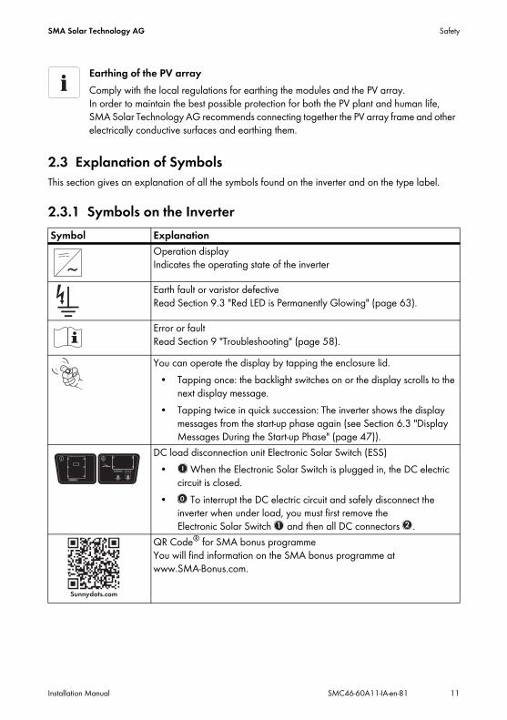
Earthing of the PV array Comply with the local regulations for earthing the modules and the PV array. In order to maintain the best possible protection for both the PV plant and human life, SMA Solar Technology AG recommends connecting together the PV array frame and other electrically conductive surfaces and earthing them.
Symbol ExplanationOperation display Indicates the operating state of the inverter
Earth fault or varistor defective Read Section 9.3 "Red LED is Permanently Glowing" (page 63).
Error or faultRead Section 9 "Troubleshooting" (page 58).You can operate the display by tapping the enclosure lid.
• Tapping once: the backlight switches on or the display scrolls to the next display message.
• Tapping twice in quick succession: The inverter shows the display messages from the start-up phase again (see Section 6.3 "Display Messages During the Start-up Phase" (page 47)).
DC load disconnection unit Electronic Solar Switch (ESS)• When the Electronic Solar Switch is plugged in, the DC electric
circuit is closed.• To interrupt the DC electric circuit and safely disconnect the
inverter when under load, you must first remove the Electronic Solar Switch and then all DC connectors .
QR Code® for SMA bonus programmeYou will find information on the SMA bonus programme at www.SMA-Bonus.com.
Safety SMA Solar Technology AG
12 SMC46-60A11-IA-en-81 Installation Manual
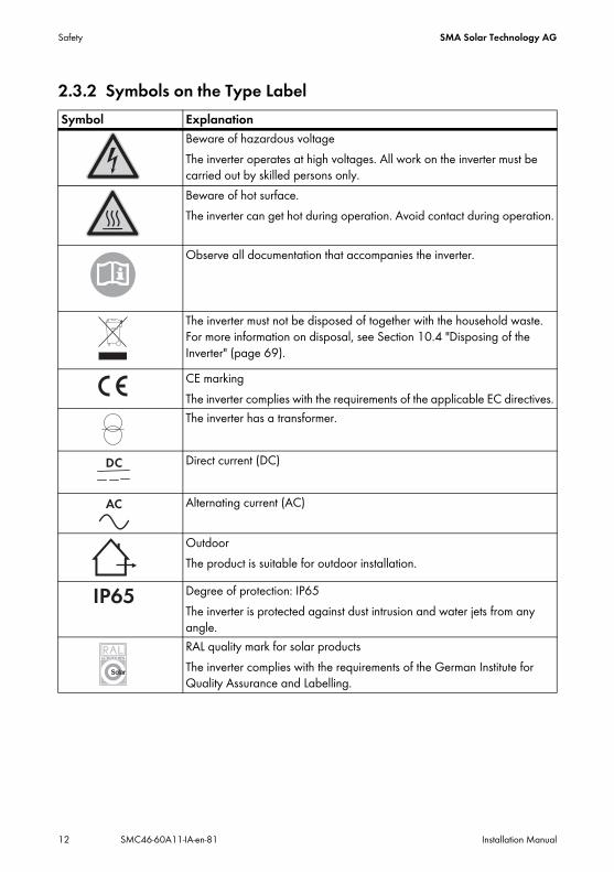
2.3.2 Symbols on the Type LabelSymbol Explanation
Beware of hazardous voltageThe inverter operates at high voltages. All work on the inverter must be carried out by skilled persons only.Beware of hot surface.The inverter can get hot during operation. Avoid contact during operation.
Observe all documentation that accompanies the inverter.
The inverter must not be disposed of together with the household waste. For more information on disposal, see Section 10.4 "Disposing of the Inverter" (page 69).CE markingThe inverter complies with the requirements of the applicable EC directives.The inverter has a transformer.
Direct current (DC)
Alternating current (AC)
OutdoorThe product is suitable for outdoor installation.
Degree of protection: IP65The inverter is protected against dust intrusion and water jets from any angle.RAL quality mark for solar productsThe inverter complies with the requirements of the German Institute for Quality Assurance and Labelling.

SMA Solar Technology AG Unpacking
Installation Manual SMC46-60A11-IA-en-81 13
3 Unpacking3.1 Scope of DeliveryCheck the delivery for completeness and any visible external damage. Contact your specialist dealer if anything is damaged or missing.
Object Quantity DescriptionA 1 Sunny Mini CentralB 1 Ventilation grid (right/left)C 1 Wall mounting bracketD 1 DC load disconnection unit Electronic Solar Switch (ESS)E 8 DC connectors (4 x positive, 4 x negative)F 8 Sealing plug for the DC connectorsG 1 Cable gland for AC connectionH 1 Counter nut for cable gland at AC connectionI 1 Clamping bracket for additional earthingK 2 Conical spring washers:
1 x for enclosure lid screws (replacement), 1 x for earth terminalL 2 Cheese-head screws (M6x16):
1 x for enclosure lid (replacement), 1 x for earth terminalM 2 Jumpers (1 x for fan test, 1 x for the SMA Power Balancer wiring)N 2 Cylinder head screws (M6x8) for securing the inverter to the wall mounting
bracketO 1 Silicone tube for insulating the SMA Power Balancer connection cableP 1 Installation manualQ 1 User manual

Unpacking SMA Solar Technology AG
14 SMC46-60A11-IA-en-81 Installation Manual
3.2 Identifying the InverterYou can identify the inverter by the type label. The type label is located on the right-hand side of the enclosure.The inverter serial number (Serial No.), the type (Type/Model) and other device-specific characteristics are specified on the type label.
R 1 Set of documents with explanations and certificatesS 1 Supplementary sheet with inverter default settings
Object Quantity Description
SMA Solar Technology AG Assembly
Installation Manual SMC46-60A11-IA-en-81 15
4 Assembly4.1 Safety
4.2 Selecting the Mounting LocationTake the following requirements into consideration when selecting the mounting location:
• The mounting method and location must be suitable for the inverter's weight and dimensions (see Section 11 "Technical Data" (page 70)).
• Mount on a solid surface.• The mounting location must be clear and safely accessible at all times without the use of
additional aids such as scaffolding or lifting platforms. If this is not the case, service work may be restricted.
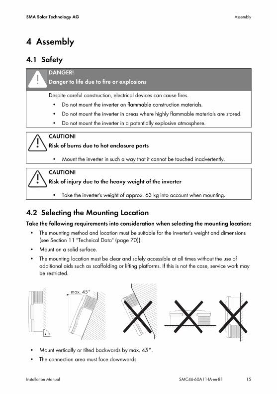
• Mount vertically or tilted backwards by max. 45°.• The connection area must face downwards.
DANGER!Danger to life due to fire or explosions
Despite careful construction, electrical devices can cause fires.• Do not mount the inverter on flammable construction materials.• Do not mount the inverter in areas where highly flammable materials are stored.• Do not mount the inverter in a potentially explosive atmosphere.
CAUTION!Risk of burns due to hot enclosure parts
• Mount the inverter in such a way that it cannot be touched inadvertently.
CAUTION!Risk of injury due to the heavy weight of the inverter
• Take the inverter's weight of approx. 63 kg into account when mounting.

Assembly SMA Solar Technology AG
16 SMC46-60A11-IA-en-81 Installation Manual
• Never mount the device with a forward tilt.• Never mount the device with a sideways tilt.• Do not mount horizontally.• Mount at eye level in order that operating states can be read at all times.• The ambient temperature should be below 40°C to ensure optimum operation.• Do not expose the inverter to direct solar irradiation as this could cause power derating due to
overheating.• In order to avoid audible vibrations in living areas, do not mount the unit on plasterboard walls
or similar. When in operation, the inverter emits noise which may be perceived as annoying in living areas.
• Observe the minimum clearances to walls, other inverters and objects as shown in the diagram in order to ensure sufficient heat dissipation and to have sufficient space for removing the Electronic Solar Switch.
Multiple inverters installed in areas with high ambient temperaturesThere must be sufficient clearance between the individual inverters to ensure that the cooling air of the adjacent inverter is not drawn in.If necessary, increase the clearances and make sure there is enough fresh-air supply to ensure sufficient cooling of the inverters.
50
0 m
m
300 mm
300 mm
50 mm
30
0 m
m

SMA Solar Technology AG Assembly
Installation Manual SMC46-60A11-IA-en-81 17
4.3 Mounting the Inverter using the Wall Mounting Bracket1. Mark the position of the drill holes using the wall mounting bracket and drill the holes. Use at
least 2 of the 6 holes, 1 hole on the left- and right-hand sides respectively.
Assembly SMA Solar Technology AG
18 SMC46-60A11-IA-en-81 Installation Manual
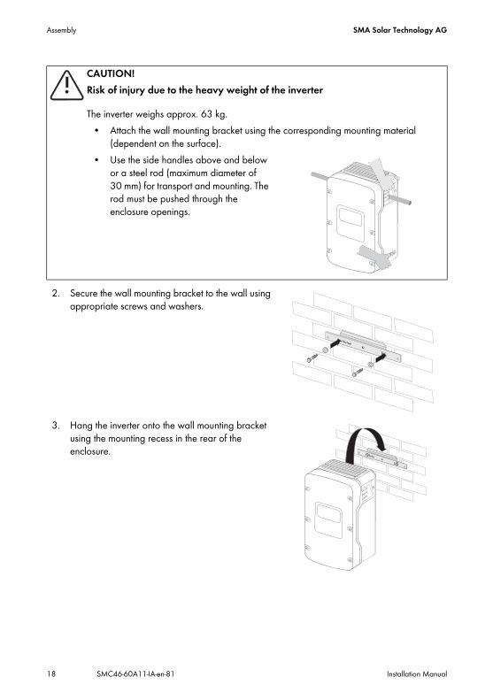
2. Secure the wall mounting bracket to the wall using appropriate screws and washers.
3. Hang the inverter onto the wall mounting bracket using the mounting recess in the rear of the enclosure.
CAUTION!Risk of injury due to the heavy weight of the inverter
The inverter weighs approx. 63 kg.• Attach the wall mounting bracket using the corresponding mounting material
(dependent on the surface).• Use the side handles above and below
or a steel rod (maximum diameter of 30 mm) for transport and mounting. The rod must be pushed through the enclosure openings.

SMA Solar Technology AG Assembly
Installation Manual SMC46-60A11-IA-en-81 19
4. Screw the inverter onto the wall mounting bracket on both sides using the screws (M6x8) provided.Only tighten the screws hand-tight.
5. Check to ensure that the inverter is securely in place.
6. Close the recessed grips using the ventilation grids supplied. To help you identify the sides, the ventilation grids are marked on the inside with "rechts/right" and "links/left". The ventilation grids prevent intrusion of dust and insects, and can be reordered from SMA Solar Technology AG as required (see Section 13 "Contact" (page 80)).
Optional Anti-Theft ProtectionTo protect the inverter against theft, the back panel can be secured to the wall at the bottom using two "safety screws".The other two holes are spares.
Electrical Connection SMA Solar Technology AG
20 SMC46-60A11-IA-en-81 Installation Manual
5 Electrical Connection
5.1 Overview of the Connection Area
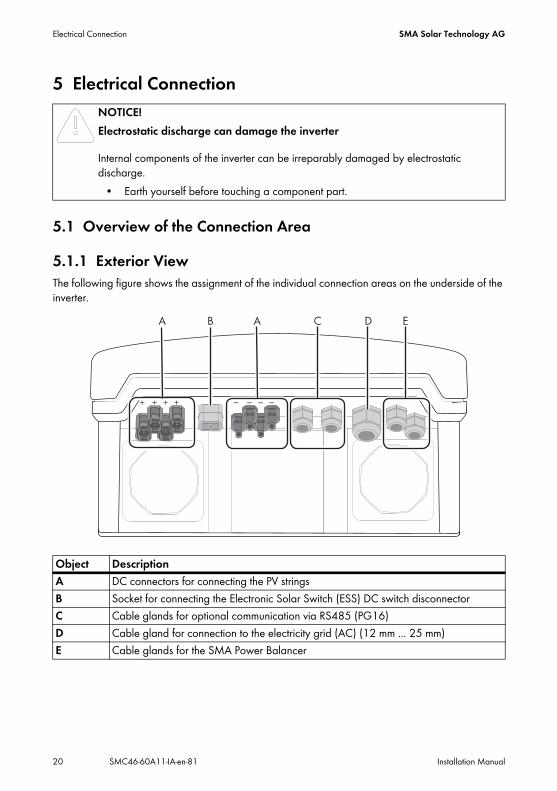
5.1.1 Exterior ViewThe following figure shows the assignment of the individual connection areas on the underside of the inverter.
NOTICE!Electrostatic discharge can damage the inverter
Internal components of the inverter can be irreparably damaged by electrostatic discharge.
• Earth yourself before touching a component part.
Object DescriptionA DC connectors for connecting the PV stringsB Socket for connecting the Electronic Solar Switch (ESS) DC switch disconnectorC Cable glands for optional communication via RS485 (PG16)D Cable gland for connection to the electricity grid (AC) (12 mm ... 25 mm)E Cable glands for the SMA Power Balancer
SMA Solar Technology AG Electrical Connection
Installation Manual SMC46-60A11-IA-en-81 21
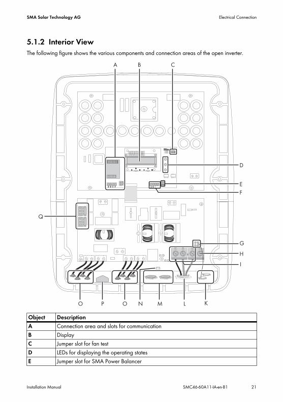
5.1.2 Interior ViewThe following figure shows the various components and connection areas of the open inverter.
Object DescriptionA Connection area and slots for communicationB DisplayC Jumper slot for fan testD LEDs for displaying the operating statesE Jumper slot for SMA Power Balancer

Electrical Connection SMA Solar Technology AG
22 SMC46-60A11-IA-en-81 Installation Manual
5.2 Connection to the Electricity Grid (AC)
5.2.1 Conditions for the AC Connection
Cable DimensioningUse Sunny Design Version 2.0 or higher for sizing the conductor cross-sections (see design software "Sunny Design" at www.SMA-Solar.com).
Cable Requirements
F Terminals for the SMA Power BalancerG Flat male tab for earthing the cable shield when connecting the SMA Power BalancerH Additional terminal for earthingI Terminals for AC cablesK Cable glands for the SMA Power BalancerL Cable gland for the AC cableM Cable glands for communicationN Screw fixture of shield connection terminal for data cableO DC connectorP Connection socket for the Electronic Solar Switch (ESS)Q Varistors
Connection requirements of the network operatorAlways observe the connection requirements of your network operator.
Halving the cable lossesIf three inverters with symmetrical feed-in are combined to form a three-phase system, the neutral conductor is not subject to any load and the cable losses are halved. Thus, the maximum possible cable length is doubled.
Item Description ValueA External diameter 12 mm … 25 mmB Conductor cross-section 6 mm² … 16 mm²C Stripping length approx. 16 mm
Object Description

SMA Solar Technology AG Electrical Connection
Installation Manual SMC46-60A11-IA-en-81 23
Load Disconnection UnitYou must install a separate miniature circuit-breaker for each inverter in order to ensure that the inverter can be securely disconnected under load. The maximum permissible fuse protection can be found in Section 11 "Technical Data" (page 70).Detailed information and examples on the design of miniature circuit-breakers are available in the Technical Information "Miniature Circuit-Breaker" to be found in the download area of SMA Solar Technology AG at www.SMA-Solar.com.
DANGER!Danger to life due to fire
When more than one inverter is connected in parallel to the same miniature circuit-breaker, the protective function of the miniature circuit-breaker is no longer guaranteed. This could result in a cable fire or destruction of the inverter.
• Never connect several inverters to the same miniature circuit-breaker.• Observe the maximum permissible fuse protection of the inverter when selecting the
miniature circuit-breaker.
DANGER!Danger to life due to fire
When a generator (inverter) and a load are connected to the same miniature circuit-breaker, the protective function of the miniature circuit-breaker is no longer guaranteed. The currents from the inverter and the electricity grid can accumulate to form overcurrents which are not detected by the miniature circuit-breaker.
• Never connect loads between the inverter and the miniature circuit-breaker without fuse protection.
• Always fuse loads separately.
NOTICE!Damage to the inverter by use of screw-type fuses as switch-disconnectors
A screw-type fuse, e.g. DIAZED fuse or NEOZED fuse, is not a switch-disconnector and thus may not be used as a load disconnection unit. A screw-type fuse only acts as cable protection.If the inverter is disconnected under load using a screw-type fuse, the inverter may be damaged.
• Use only a switch-disconnector or a miniature circuit-breaker as a load disconnection unit.

Electrical Connection SMA Solar Technology AG
24 SMC46-60A11-IA-en-81 Installation Manual
5.2.2 Connecting the Inverter to the Electricity Grid (AC)1. Check the mains voltage and compare with "VAC, nom" on the type label.
The exact operating range of the inverter is specified in the operating parameters. The corresponding document is available in the download area at www.SMA-Solar.com.
2. Disconnect the miniature circuit-breaker and secure against reconnection.3. Loosen all screws of the enclosure lid and remove
the lid.
4. Remove the adhesive tape from the AC enclosure opening (see "D" on Page 20).5. Insert the AC cable gland from the outside into the enclosure opening and tighten it from the
inside using the counter nut.6. Unscrew the cable gland's swivel nut and lead it over the cable.7. Lead the cable through the cable gland to the AC terminal.8. Connect L, N and the protective conductor (PE) in
accordance with the labelling to the terminal blocks using a screwdriver. The PE wire must be 5 mm longer than the L and N conductors.L and N must not be swapped.

SMA Solar Technology AG Electrical Connection
Installation Manual SMC46-60A11-IA-en-81 25
9. Screw the swivel nut firmly onto the cable gland.10. Secure the enclosure lid using all of the screws and
the corresponding conical spring washers.Tighten the screws with 6 Nm torque in the order shown in the figure on the right. The toothing of the conical spring washers must be facing the enclosure lid.The scope of delivery of the inverter includes a spare screw and conical spring washer.
The inverter is connected to the electricity grid (AC).
5.2.3 Additional Earthing of the EnclosureIf the installation so requires, you can use the earth terminal to connect a second protective conductor or as equipotential bonding.Procedure1. Plug the stripped earthing cable (D) under the
clamping bracket (C) (max. cross-section 16 mm² or with bootlace ferrule max. 10 mm²).
2. Screw the clamping bracket tight using the screw (A) and conical spring washer (B).The toothing of the conical spring washer must face toward the clamping bracket.
The inverter enclosure is additionally earthed.
DANGER!Danger to life due to enclosure lid carrying voltage
The earthing of the enclosure lid is ensured by the conical spring washers.• Attach the conical spring washers for all 6 screws with the toothing facing towards
the enclosure lid.
DANGER!Danger to life due to high voltages in the inverter
• Do not switch on the miniature circuit-breaker until the PV array has also been connected and the inverter is securely closed.
Electrical Connection SMA Solar Technology AG
26 SMC46-60A11-IA-en-81 Installation Manual
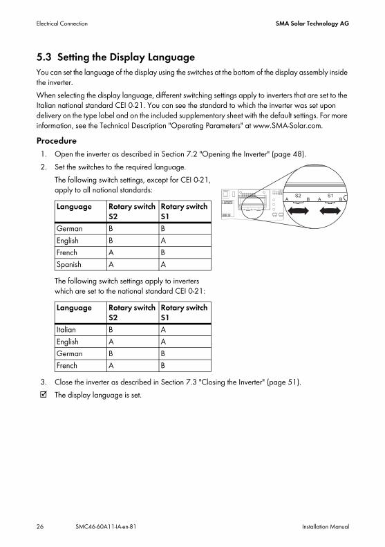
5.3 Setting the Display LanguageYou can set the language of the display using the switches at the bottom of the display assembly inside the inverter.When selecting the display language, different switching settings apply to inverters that are set to the Italian national standard CEI 0-21. You can see the standard to which the inverter was set upon delivery on the type label and on the included supplementary sheet with the default settings. For more information, see the Technical Description "Operating Parameters" at www.SMA-Solar.com.Procedure1. Open the inverter as described in Section 7.2 "Opening the Inverter" (page 48).2. Set the switches to the required language.
The following switch settings, except for CEI 0-21, apply to all national standards:
The following switch settings apply to inverters which are set to the national standard CEI 0-21:
3. Close the inverter as described in Section 7.3 "Closing the Inverter" (page 51). The display language is set.
Language Rotary switch S2
Rotary switch S1
German B BEnglish B AFrench A BSpanish A A
Language Rotary switch S2
Rotary switch S1
Italian B AEnglish A AGerman B BFrench A B

SMA Solar Technology AG Electrical Connection
Installation Manual SMC46-60A11-IA-en-81 27
5.4 Connecting the PV Array (DC)
5.4.1 Conditions for DC Connection
• Requirements for the PV modules of the connected strings:– same type– same quantity– identical alignment– identical tilt
• The connection cables of the PV modules must be equipped with connectors. The connectors required for DC connection are included in the scope of delivery.
• The following thresholds at the DC input of the inverter must not be exceeded:
Using Y adaptors for the parallel connection of stringsY adaptors must not be visible or freely accessible in close proximity to the inverter.
• The DC circuit must not be interrupted by Y adaptors.• Observe the procedure for disconnecting the inverter as described in Section 7.2
"Opening the Inverter" (page 48).
Maximum input voltage Maximum input current600 V (DC) 26.0 A (DC)
WARNING!Danger to life due to electric shock or fire
The maximum possible input current per string is limited by the connectors used. If the connectors are overloaded, an electric arc may occur and there is a risk of fire.
• Ensure that the input current per string does not exceed the maximum through-fault current of the connectors used.
Electrical Connection SMA Solar Technology AG
28 SMC46-60A11-IA-en-81 Installation Manual
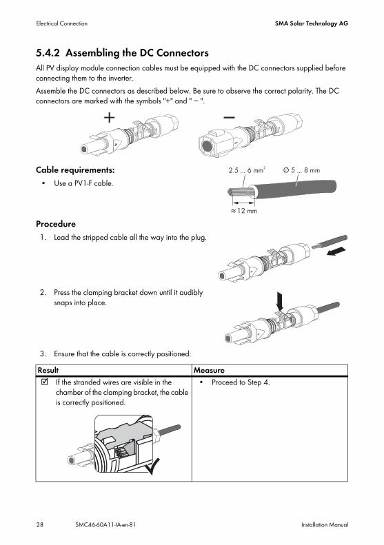
5.4.2 Assembling the DC ConnectorsAll PV display module connection cables must be equipped with the DC connectors supplied before connecting them to the inverter. Assemble the DC connectors as described below. Be sure to observe the correct polarity. The DC connectors are marked with the symbols "+" and " − ".
Cable requirements:• Use a PV1-F cable.
Procedure1. Lead the stripped cable all the way into the plug.
2. Press the clamping bracket down until it audibly snaps into place.
3. Ensure that the cable is correctly positioned:Result Measure If the stranded wires are visible in the
chamber of the clamping bracket, the cable is correctly positioned.
• Proceed to Step 4.
... ...
SMA Solar Technology AG Electrical Connection
Installation Manual SMC46-60A11-IA-en-81 29
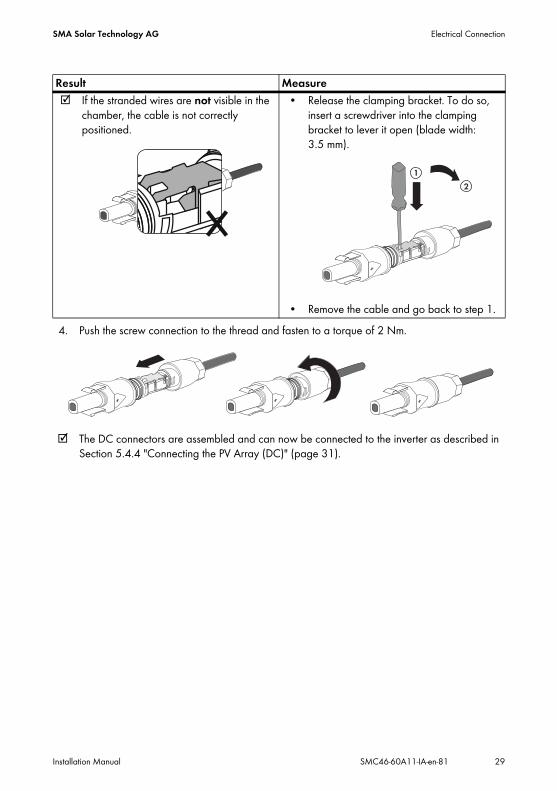
4. Push the screw connection to the thread and fasten to a torque of 2 Nm.
The DC connectors are assembled and can now be connected to the inverter as described in Section 5.4.4 "Connecting the PV Array (DC)" (page 31).
If the stranded wires are not visible in the chamber, the cable is not correctly positioned.
• Release the clamping bracket. To do so, insert a screwdriver into the clamping bracket to lever it open (blade width: 3.5 mm).
• Remove the cable and go back to step 1.
Result Measure

Electrical Connection SMA Solar Technology AG
30 SMC46-60A11-IA-en-81 Installation Manual
5.4.3 Opening the DC Connector1. Unscrew the screw connection.
2. Unlock the DC connector: Insert a screwdriver into the snap slot on the side and lever it out (blade width: 3.5 mm).
3. Carefully pull the DC connector apart.
4. Release the clamping bracket. To do so, insert a screwdriver into the clamping bracket to lever it open (blade width: 3.5 mm).
5. Remove the cable.
The cable is now detached from the DC connector.

SMA Solar Technology AG Electrical Connection
Installation Manual SMC46-60A11-IA-en-81 31
5.4.4 Connecting the PV Array (DC)
1. Disconnect the miniature circuit-breaker and secure against reconnection.2. Pull the Electronic Solar Switch downward, slightly
towards the wall.
3. Check the connection cable of the PV modules for correct polarity and make sure that the maximum input voltage of the inverter is not exceeded.At an ambient temperature above 10°C, the open-circuit voltage of the PV modules must not be more than 90% of the maximum inverter input voltage. If this is not the case, review the plant design and the PV module circuitry. At lower ambient temperatures, the maximum input voltage of the inverter could otherwise be exceeded.
DANGER!Danger to life due to high voltages in the inverter
• Before connecting the PV array, ensure that the miniature circuit-breaker is switched off.
NOTICE!Excessive voltages can destroy the multimeter
• Only use multimeters with a DC input voltage range of up to at least 1,000 V.
NOTICE!Destruction of the inverter due to overvoltage
If the voltage of the PV modules exceeds the maximum input voltage of the inverter, the inverter could be destroyed by overvoltage.This will void all warranty claims.
• Do not connect strings with an open-circuit voltage greater than the maximum input voltage of the inverter.
• Check the plant design.

Electrical Connection SMA Solar Technology AG
32 SMC46-60A11-IA-en-81 Installation Manual
4. Check the strings for earth faults as described in Section 9.3.1 "Checking the PV Array for Earth Faults" (page 64).
5. Connect the assembled DC connectors to the inverter. The DC connectors click audibly into place.
6. In order to seal the inverter, all unused DC inputs must be closed using DC connectors and sealing plugs:
– For unused DC connectors, push down the clamping bracket and push the screw connection up to the thread.
– Insert the sealing plug into the DC connector.
– Tighten the DC connector (torque: 2 Nm).
Sealing plugs• Do not insert the sealing plugs directly into the DC inputs on the inverter.
+
1
2
+
+

SMA Solar Technology AG Electrical Connection
Installation Manual SMC46-60A11-IA-en-81 33
– Insert the DC connectors with sealing plugs into the corresponding DC inputs on the inverter.
The DC connectors click audibly into place.
7. Ensure that all DC connectors are securely in place.8. Check the Electronic Solar Switch for wear, as
described in Section 8.3 "Checking the Electronic Solar Switch (ESS) for Wear" (page 57) and attach it firmly.
The PV array is connected. You can now commission the inverter as described in Section 6 "Commissioning" (page 44). The following connections are optional.
NOTICE!Damage to the inverter due to moisture and dust intrusion
If the Electronic Solar Switch is not plugged in or incorrectly plugged in during operation, moisture and dust can penetrate the inverter.If the Electronic Solar Switch is not correctly plugged in, this can cause contacts to wear in the Electronic Solar Switch or the Electronic Solar Switch might fall out. This can result in yield loss and damage to the Electronic Solar Switch.Always plug in the Electronic Solar Switch as described in the following:
• Do not tighten the screw in the Electronic Solar Switch.• Firmly plug in the Electronic Solar Switch until it is flush with the enclosure.• Ensure that the maximum distance between the Electronic Solar Switch and the
enclosure is 1 mm.

Electrical Connection SMA Solar Technology AG
34 SMC46-60A11-IA-en-81 Installation Manual
5.5 Connecting the SMA Power BalancerThe Sunny Mini Central is equipped with the SMA Power Balancer as standard. This enables a circuitry of three Sunny Mini Central inverters to a three-phase feed-in system.Each of the three Sunny Mini Central inverters in a group must be connected to a different line conductor of the low-voltage grid (L1, L2 and L3).
By activating this electronic circuit, you can stipulate how the other two Sunny Mini Central inverters are to react if there is a device fault with the third Sunny Mini Central or there is a mains voltage fault in its line conductor.
The connections for the SMA Power Balancer are galvanically isolated from the rest of the Sunny Mini Central electronic circuit.
5.5.1 ConfigurationIf the national standard VDE-AR-N4105-MP or VDE-AR-N4105-HP is set, the SMA Power Balancer is activated by default and set to the operating mode "PowerGuard" in SMC 4600A-11, SMC 5000A-11 and SMC 6000A-11. All other national standards deactivate the SMA Power Balancer by default in SMC 4600A-11, SMC 5000A-11 and SMC 6000A-11.The SMA Power Balancer is always deactivated by default in SMC 4600A, SMC 5000A and SMC 6000A, regardless of the national standard set.The SMA Power Balancer can only be activated or configured using a communication product. To change the "PowerBalancer" parameter, you need a personal access code – the so-called SMA Grid Guard code. The application form for the personal access code is available in the download area at www.SMA-Solar.com, in the "Certificate" category of the respective inverter.The configuration options are described below.
Three-Phase Grid ConnectionFor further information on this subject, see the Technical Information "Three-Phase Grid Connection with Sunny Mini Central" in the download area at www.SMA-Solar.com.

SMA Solar Technology AG Electrical Connection
Installation Manual SMC46-60A11-IA-en-81 35
Configuration OptionsThere are four different configuration options for the "PowerBalancer" parameter.
• FaultGuardThis operating mode allows for the implementation of a three-phase mains voltage monitoring, which also reacts to device faults.– If one of the three inverters indicates a mains voltage fault and stops feeding in, the other
two inverters also disconnect from the electricity grid immediately.
– If one of the three inverters indicates a device fault and stops feeding in, the other two inverters also disconnect from the electricity grid after five minutes.
Local connection requirementsSelect the respective setting and always observe the local connection requirements and provisions of your network operator.

Electrical Connection SMA Solar Technology AG
36 SMC46-60A11-IA-en-81 Installation Manual
• PhaseGuardThis operating mode allows for the implementation of three-phase mains voltage monitoring. – If one of the three inverters indicates a mains voltage fault and stops feeding in, the other
two inverters also disconnect from the electricity grid automatically.
– If one of the three inverters indicates a device fault and stops feeding in, the other two inverters are not affected and continue to feed in at full power.

SMA Solar Technology AG Electrical Connection
Installation Manual SMC46-60A11-IA-en-81 37
• OffThe SMA Power Balancer is deactivated (default setting). – If one of the inverters displays a device fault or a mains voltage fault, only the affected
inverter disconnects from the electricity grid and the other two inverters continue to feed in at full power.
• PowerGuardThis setting can be selected if the entire PV plant only consists of three Sunny Mini Central inverters and in the event of a malfunction, the unbalanced load should be limited to 4.6 kVA over a 10-minute average.
– If one of the three inverters indicates a mains voltage fault or device fault and stops feeding in, the other two inverters automatically limit their power over a 10 minute average to 4.6 kVA.
Different unbalanced load limitation for SMC 6000A-11 inverters for ItalyThe unbalanced load for SMC 6000A-11 inverters set to the national standard CEI 0-21 is limited to 6 kVA over a 10-minute average.
Electrical Connection SMA Solar Technology AG
38 SMC46-60A11-IA-en-81 Installation Manual
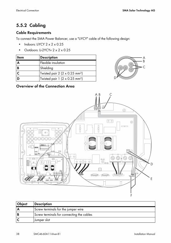
5.5.2 CablingCable RequirementsTo connect the SMA Power Balancer, use a "LiYCY" cable of the following design:
• Indoors: LiYCY 2 x 2 x 0.25• Outdoors: Li-2YCYv 2 x 2 x 0.25
Overview of the Connection Area
Item DescriptionA Flexible insulationB ShieldingC Twisted pair 2 (2 x 0.25 mm²)D Twisted pair 1 (2 x 0.25 mm²)
Object DescriptionA Screw terminals for the jumper wireB Screw terminals for connecting the cablesC Jumper slot

SMA Solar Technology AG Electrical Connection
Installation Manual SMC46-60A11-IA-en-81 39
Procedure1. Open the inverter as described in Section 7.2 "Opening the Inverter" (page 48).2. Insert the cables into each inverter.
Use one of the two enclosure openings (F) on the right-hand side.
3. Lead the cable along the cable route (E) as far as the terminal block (B).4. Earth the cable shield in each inverter at the PE terminal (D).5. Sheath the positive and negative cable conductors in each inverter using bootlace ferrules.6. Connect the positive and negative poles to the
corresponding screw terminals.
7. In order to link the three inverters, connect the positive and negative conductors from the two other inverters to the terminal block of the middle inverter.
The cable length between 2 inverters may not exceed 300 m.
D Flat male tab for earthing the cable shieldE Silicone tube/cable routeF Cable glands
DANGER!Danger to life due to high voltage in the event of a fault in the SMA Power Balancer cable
• Sheath the positive and negative cable conductors in each inverter using the silicone tube supplied.
• Cut the silicone tube to the required length.• The silicone tube must completely cover the cable inside the inverter enclosure.
Object Description

Electrical Connection SMA Solar Technology AG
40 SMC46-60A11-IA-en-81 Installation Manual
8. Only plug one of the provided jumpers into the lowest of the three slots in the middle inverter (the one with two insulated wires for each terminal) as depicted on the right.Do not plug the jumpers in the lowest slot of the two other inverters.orBridge the "A" and "B" screw terminals on the middle inverter using a jumper wire.Do not bridge the "A" and "B" screw terminals in the two other inverters.
9. Measure the electrical resistance between the positive and negative poles of the terminal block in the middle inverter. If the resistance is approximately 27.8 k Ω
(±370 Ω ), the SMA Power Balancer has been connected correctly. If not, check the cabling.
10. Close all inverters as described in Section 7.3 "Closing the Inverter" (page 51).Connection with a Sunny Mini Central 9000TL, 10000TL or 11000TLIn order to be able to connect the SMA Power Balancer to a Sunny Mini Central 9000TL, 10000TL or 11000TL, the Sunny Mini Central 4600A, 5000A, 6000A must be equipped with a special plug. Three inverters are then connected together using a special connection cable.You can order the plug and the connection cable from SMA Solar Technology AG or your specialist dealer. Section 12 "Accessories" (page 79) contains a list of the order numbers.
SMA Solar Technology AG Electrical Connection
Installation Manual SMC46-60A11-IA-en-81 41
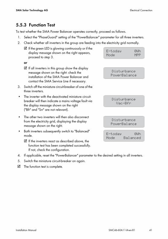
5.5.3 Function TestTo test whether the SMA Power Balancer operates correctly, proceed as follows.1. Select the "PhaseGuard" setting of the "PowerBalancer" parameter for all three inverters.2. Check whether all inverters in the group are feeding into the electricity grid normally.
If the green LED is glowing continuously or if the display message shown on the right appears, proceed to step 3.
or If all inverters in this group show the display
message shown on the right: check the installation of the SMA Power Balancer and contact the SMA Service Line if necessary.
3. Switch off the miniature circuit-breaker of one of the three inverters.
• The inverter with the deactivated miniature circuit-breaker will then indicate a mains voltage fault via the display message shown on the right ("Bfr" and "Srr" are not relevant).
• The other two inverters will then also disconnect from the electricity grid, displaying the display message shown on the right.
• Both inverters subsequently switch to "Balanced" mode. If the inverters react as described above, the
function test has been completed successfully. If not, check the configuration.
4. If applicable, reset the "PowerBalancer" parameter to the desired setting in all inverters.5. Switch the miniature circuit-breaker on again. The function test is complete.

Electrical Connection SMA Solar Technology AG
42 SMC46-60A11-IA-en-81 Installation Manual
5.6 CommunicationThe inverter is equipped with a slot for communication interfaces in order to communicate with special data loggers (e.g., Sunny WebBox) or a PC with corresponding software (e.g., Sunny Data Control or Sunny Explorer).Refer to the respective communication interface manual for a detailed wiring diagram and an installation description for the interface.The active power of the inverter can be limited or its displacement power factor can be set externally using the Power Reducer Box from SMA Solar Technology AG. Detailed information on the Power Reducer Box is available in its technical description at www.SMA-Solar.com.
5.7 Setting the Grid and Country Parameters
A detailed description of the operating parameters for the inverter is available in the download area at www.SMA-Solar.com in the category "Technical Description" of the respective inverter.
5.7.1 Setting the Installation CountryUsing the "Default" parameter, you can set the country of installation and/or the grid connection standard valid for that country via a communication product (e.g., Sunny WebBox) or a PC with corresponding software (e.g., Sunny Data Control or Sunny Explorer). This, however, is only required if the inverter was originally ordered for another country. You can see the standard to which the inverter was set upon delivery on the type label and on the included supplementary sheet with the default settings.
Changing grid-relevant parameters and country parametersTo change grid-relevant parameters, you need a personal access code – the so-called SMA Grid Guard code. The application form for the personal access code is available in the download area at www.SMA-Solar.com, in the "Certificate" category of the respective inverter. You must discuss changes to these parameters with your network operator.

SMA Solar Technology AG Electrical Connection
Installation Manual SMC46-60A11-IA-en-81 43
5.7.2 Setting the Stand-Alone Grid OperationTo operate the inverter in an off-grid system with Sunny Island, you must set the "Default" parameter to stand-alone grid ("OFF-Grid") operation.There are several ways of setting the inverter to stand-alone grid operation:
• Setting via Sunny WebBoxor
• Setting via Sunny Data Control or Sunny Explorer
5.7.3 Additional Country Parameters
The deactivation criteria (voltage, frequency, impedance) are specified via country parameters as with all Sunny Mini Central inverters.The additional default country parameter "MVtgDirective" expands the deactivation limits of the inverter for voltage and frequency to a maximum/minimum. This country setting may only be selected if the PV plant or the inverter is operated with external three-phase decoupling protection, which will automatically disconnect the inverter from the electricity grid if non-permissible voltage and frequency values occur. Device protection is still guaranteed.
DANGER!Danger to life due to high voltages in the event of electricity grid failure
If you set the inverter to stand-alone grid operation, it does not fulfil any country-specific standards or guidelines. If there is an electricity grid outage, there will consequently be a danger of backfeed.
• Never operate the inverter directly on the electricity grid when set to stand-alone grid operation.
Requirement for the settingSet the installation country as described in Section 5.7.1 "Setting the Installation Country" (page 42) before setting the country parameter described here.
DANGER!Danger to life due to electric shock if external decoupling protection is missing
With the country setting "MVtgDirective", the inverter may only be operated with an external three-phase decoupling protection device which complies with the country-specific requirements.Without such external decoupling protection, the inverter will not disconnect from the electricity grid when the standard requirement is exceeded.
• Install external three-phase decoupling protection.

Commissioning SMA Solar Technology AG
44 SMC46-60A11-IA-en-81 Installation Manual
6 Commissioning6.1 Commissioning the Inverter1. Check the following requirements before commissioning:
– The inverter is securely in place– AC cables are correctly connected (electricity grid)– DC cables (PV strings) are fully connected– Unused DC inputs are closed using the corresponding DC connectors and sealing plugs– The enclosure lid is securely screwed into place– The Electronic Solar Switch is securely connected– The miniature circuit-breaker is correctly sized
2. Switch the miniature circuit-breaker on. All three LEDs glowing or flashing: the startup phase commences. Green LED is glowing: commissioning successful.or Green LED will flash if irradiation is insufficient: grid connection conditions have not yet been
reached. Wait for sufficient irradiation.or The red or yellow LED is glowing or flashing: there is a disturbance. Proceed to step 3.
3. Read Section 9 "Troubleshooting" (page 58) and if necessary, eliminate the fault or disturbance.
A Green LED OperationB Red LED Earth fault or varistor defectiveC Yellow LED Disturbance
Self-test in accordance with CEI 0-21 during initial start-up of SMC 6000A (applies to Italy only)The Italian standard CEI 0-21 prescribes that an inverter can only operate on the electricity grid after the disconnection times for overvoltage, undervoltage, minimum frequency and maximum frequency have been checked.Start the self-test as described in Section 6.2 "Only for Italy: Self-Test in Accordance with CEI 0-21" (page 45). The test takes approx. 8 minutes.
SMA Solar Technology AG Commissioning
Installation Manual SMC46-60A11-IA-en-81 45
6.2 Only for Italy: Self-Test in Accordance with CEI 0-21
6.2.1 Starting the Self-TestThe self-test only applies to inverters of type SMC 6000A-11 which are commissioned in Italy.The Italian standard requires that all inverters in plants ≤ 6 kW feeding into the electricity grid perform a self-test in accordance with CEI 0-21. During the self-test, the inverter will check the reaction times for overvoltage consecutetively, undervoltage, maximum frequency and minimum frequency.The self-test changes the upper and lower trip-limit values for each protective function on a linear basis for frequency monitoring and voltage monitoring. As soon as the measured value exceeds the permitted trip-limit value, the inverter disconnects from the electricity grid. In this way, the inverter determines the reaction time and checks itself.After the self-test has been completed, the inverter automatically switches back to the feed-in operation, resets the original shutdown conditions and connects to the electricity grid.Requirements:
• Country data set must be configured to CEI0-21 Int / CEI 0-21 intern.or
• Country data set must be configured to trimmed / Special setting based on CEI0-21 Int / CEI 0-21 intern.
• A report for entering the test results in compliance with CEI 0-21 must be available.• The inverter must be in operation and in the start-up phase.1. As soon as the configured country data set appears in the display, tap once on the display
within ten seconds. A message informing you that the self-test has started is shown in the display:
Avvio Autotest.If the information Avvio Autotest is not shown in the display, the period of ten seconds has expired and the self-test does not start.– Restart the self-test (see Section 6.2.3).
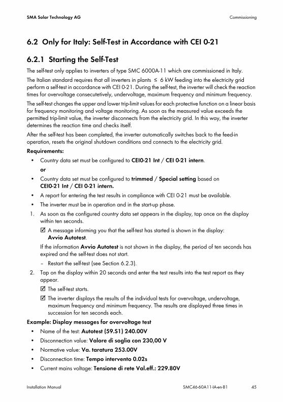
2. Tap on the display within 20 seconds and enter the test results into the test report as they appear. The self-test starts. The inverter displays the results of the individual tests for overvoltage, undervoltage,
maximum frequency and minimum frequency. The results are displayed three times in succession for ten seconds each.
Example: Display messages for overvoltage test• Name of the test: Autotest (59.S1) 240.00V• Disconnection value: Valore di soglia con 230,00 V• Normative value: Va. taratura 253.00V• Disconnection time: Tempo intervento 0.02s• Current mains voltage: Tensione di rete Val.eff.: 229.80V
Commissioning SMA Solar Technology AG
46 SMC46-60A11-IA-en-81 Installation Manual
6.2.2 Abortion of the Self-TestIf, during the self-test, an unexpected disconnection requirement occurs, the self-test is aborted. The same applies if the DC voltage is so low that feed-in cannot be continued.
• A message informing you that the self-test has been aborted is shown in the display for ten seconds: Autotest interroto.
• Restart the self-test (see Section 6.2.3).
6.2.3 Restarting the Self-Test1. Disconnect the miniature circuit-breaker and secure against reconnection. 2. Remove the ESS from the inverter for five minutes and then plug it in again firmly.
3. Restart the inverter The inverter is once again in the start-up phase and you can start the self-test
(see Section 6.2.1).
NOTICE!Damage to the inverter due to moisture and dust intrusion
If the Electronic Solar Switch is not plugged in or incorrectly plugged in during operation, moisture and dust can penetrate the inverter.If the Electronic Solar Switch is not correctly plugged in, this can cause contacts to wear in the Electronic Solar Switch or the Electronic Solar Switch might fall down. This can result in yield loss and damage to the Electronic Solar Switch.Always plug in the Electronic Solar Switch as described in the following:
• Do not tighten the screw in the Electronic Solar Switch.• Firmly plug in the Electronic Solar Switch until it is flush with the enclosure.• Ensure that the maximum distance between the Electronic Solar Switch and the
enclosure is 1 mm.
SMA Solar Technology AG Commissioning
Installation Manual SMC46-60A11-IA-en-81 47
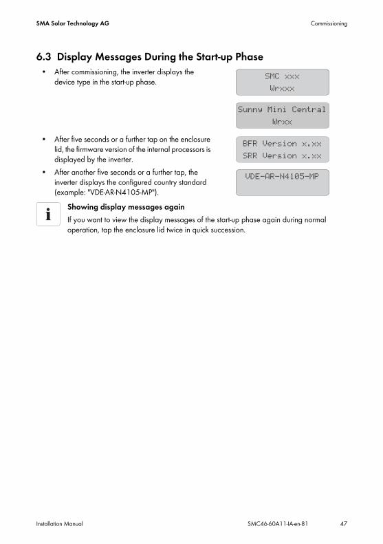
6.3 Display Messages During the Start-up Phase• After commissioning, the inverter displays the
device type in the start-up phase.
• After five seconds or a further tap on the enclosure lid, the firmware version of the internal processors is displayed by the inverter.
• After another five seconds or a further tap, the inverter displays the configured country standard (example: "VDE-AR-N4105-MP").
Showing display messages againIf you want to view the display messages of the start-up phase again during normal operation, tap the enclosure lid twice in quick succession.

Opening and Closing SMA Solar Technology AG
48 SMC46-60A11-IA-en-81 Installation Manual
7 Opening and Closing7.1 Safety
7.2 Opening the Inverter1. Disconnect the miniature circuit-breaker and secure against reconnection.2. Pull the Electronic Solar Switch downward, slightly
towards the wall.
3. Use a current clamp to ensure that no current is present in all of the DC cables. If current is present, check the installation.
DANGER!Danger to life due to electric shock
Before opening the inverter, observe the following:• Ensure that no voltage is present on the AC side.• Ensure that neither voltage nor current is present on the DC side.
NOTICE!Electrostatic discharge can damage the inverter
The internal components of the inverter can be irreparably damaged by electrostatic discharge.
• Earth yourself before touching a component part.

SMA Solar Technology AG Opening and Closing
Installation Manual SMC46-60A11-IA-en-81 49
4. Release and disconnect all DC connectors. To do this, insert a flat-blade screwdriver (blade width: 3.5 mm) into one of the side slots and pull the DC plug connectors straight out. Do NOT PULL ON THE CABLE.
All DC connectors are now disconnected from the inverter. The inverter is completely disconnected from the PV array.
5. Ensure that no voltage is present at the DC plugs on the inverter. If voltage is present, check the installation.
DANGER!Danger to life due to high voltages in the inverter
The capacitors in the inverter take 5 minutes to discharge.• Wait 5 minutes before opening the inverter.
Opening and Closing SMA Solar Technology AG
50 SMC46-60A11-IA-en-81 Installation Manual
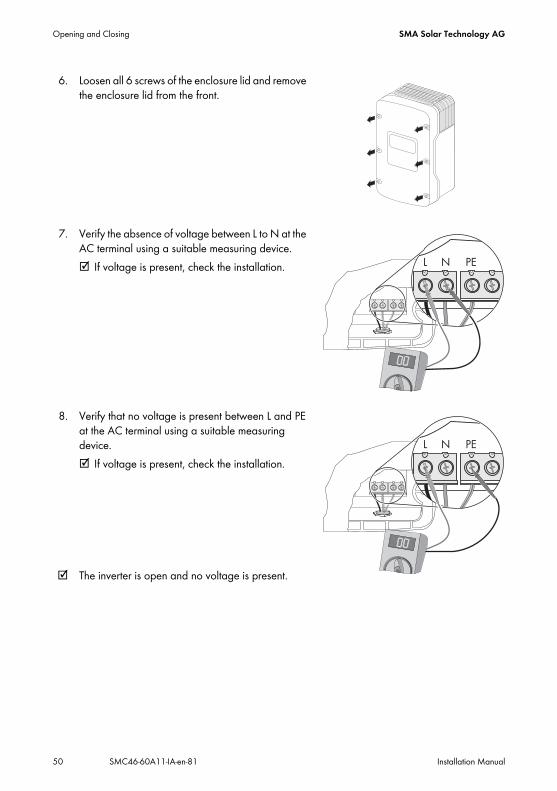
6. Loosen all 6 screws of the enclosure lid and remove the enclosure lid from the front.
7. Verify the absence of voltage between L to N at the AC terminal using a suitable measuring device. If voltage is present, check the installation.
8. Verify that no voltage is present between L and PE at the AC terminal using a suitable measuring device. If voltage is present, check the installation.
The inverter is open and no voltage is present.

SMA Solar Technology AG Opening and Closing
Installation Manual SMC46-60A11-IA-en-81 51
7.3 Closing the Inverter1. Screw the enclosure lid on using the six screws and
the corresponding conical spring washers.Tighten the screws with 6 Nm torque in the order shown in the figure on the right. The toothing of the conical spring washers must be facing the enclosure lid.The scope of delivery of the inverter includes a spare screw and conical spring washer.
2. Check the DC connectors for correct polarity and plug them in. To release the DC connectors see Section 7.2 "Opening the Inverter" (page 48).
3. Close all the DC inputs that are not needed as described in Section 5.4.4 "Connecting the PV Array (DC)" (page 31) to seal the inverter.
DANGER!Danger to life due to enclosure lid carrying voltage
The earthing of the enclosure lid is ensured by the conical spring washers.• Attach the conical spring washers for all six screws with the toothing facing towards
the enclosure lid.

Opening and Closing SMA Solar Technology AG
52 SMC46-60A11-IA-en-81 Installation Manual
4. Check the Electronic Solar Switch for wear as described in Section 8.3 and attach it firmly.
5. Switch the miniature circuit-breaker on.6. Check whether the display and the LEDs indicate a
normal operating state (see Section 6 "Commissioning" (page 44)).
The inverter is now closed and in operation.
NOTICE!Damage to the inverter due to moisture and dust intrusion
If the Electronic Solar Switch is not plugged in or incorrectly plugged in during operation, moisture and dust can penetrate the inverter.If the Electronic Solar Switch is not correctly plugged in, this can cause contacts to wear in the Electronic Solar Switch or the Electronic Solar Switch might fall down. This can result in yield loss and damage to the Electronic Solar Switch.Always plug in the Electronic Solar Switch as described in the following:
• Do not tighten the screw in the Electronic Solar Switch.• Firmly plug in the Electronic Solar Switch until it is flush with the enclosure.• Ensure that the maximum distance between the Electronic Solar Switch and the
enclosure is 1 mm.

SMA Solar Technology AG Maintenance and Cleaning
Installation Manual SMC46-60A11-IA-en-81 53
8 Maintenance and Cleaning8.1 Cleaning the InverterIf the inverter is dirty and it is difficult to read the operating data and operating states of the inverter, clean the enclosure lid, the display and the LEDs using a damp cloth. Do not use any corrosive substances (e.g. solvents or abrasives) for cleaning.
8.2 Checking Heat Dissipation
8.2.1 Cleaning the FansIf the fan guards are soiled with loose dust, they can be cleaned using a vacuum cleaner. If you do not achieve satisfactory results with a vacuum cleaner, dismantle the fans for cleaning.Procedure1. Disconnect the inverter from both the DC and AC sides as described in Section 7.2 "Opening
the Inverter" (page 48).2. Wait for the fans to stop rotating.
Cleaning the fan guards3. Remove the fan guards:
– Use a screwdriver to press both latches at the right edge of the fan guard to the right and dislodge it from the retainer.
– Carefully remove the fan guard.
4. Clean the fan guard using a soft brush, a paint brush, a cloth or compressed air.
Maintenance and Cleaning SMA Solar Technology AG
54 SMC46-60A11-IA-en-81 Installation Manual
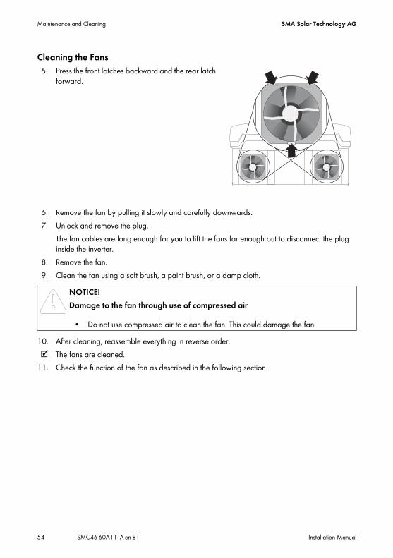
Cleaning the Fans5. Press the front latches backward and the rear latch
forward.
6. Remove the fan by pulling it slowly and carefully downwards.7. Unlock and remove the plug.
The fan cables are long enough for you to lift the fans far enough out to disconnect the plug inside the inverter.
8. Remove the fan.9. Clean the fan using a soft brush, a paint brush, or a damp cloth.
10. After cleaning, reassemble everything in reverse order. The fans are cleaned.
11. Check the function of the fan as described in the following section.
NOTICE!Damage to the fan through use of compressed air
• Do not use compressed air to clean the fan. This could damage the fan.

SMA Solar Technology AG Maintenance and Cleaning
Installation Manual SMC46-60A11-IA-en-81 55
8.2.2 Checking the FansThere are two ways to check that the fans are working:
• Set the "Fan Test" parameter to "1" in the installer mode using Sunny Data Control, Sunny Explorer or Sunny WebBox.or
• Plug the provided jumper into the system control board.Setting Parameters1. Request the installer password from the SMA Service Line (contact: see Page 80).2. Set the "Fan-Test" parameter to "1" in the installer mode.3. Check the air flow of the fans.
The inverter draws air in from underneath and then blows it back out on either side at the top. Listen for any unusual noise, which could indicate incorrect installation or a fault in the fans.
4. After checking the fans, set the "Fan-Test" parameter back to "0". The fan test is now complete.
Plugging the JumperThe inverter recognizes the jumper only after a system restart (i.e. all LEDs must have gone out prior to restart).1. Open the inverter as described in Section 7.2 "Opening the Inverter" (page 48).2. Plug the provided jumper in the slot on the system control board as shown below.
3. Close the inverter as described in Section 7.3 "Closing the Inverter" (page 51).4. Check the air flow of the fans.
The inverter draws air in from underneath and then blows it back out on either side at the top. Listen for any unusual noise, which could indicate incorrect installation or a fault in the fans.
5. After checking the fans, remove the jumper. Open and close the inverter as described in Section 7 "Opening and Closing" (page 48).
The fan test is now complete.
Maintenance and Cleaning SMA Solar Technology AG
56 SMC46-60A11-IA-en-81 Installation Manual
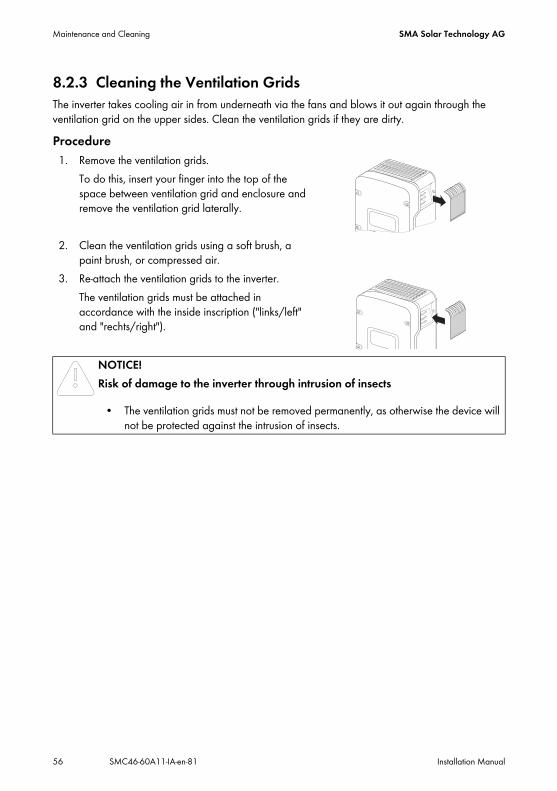
8.2.3 Cleaning the Ventilation GridsThe inverter takes cooling air in from underneath via the fans and blows it out again through the ventilation grid on the upper sides. Clean the ventilation grids if they are dirty.Procedure1. Remove the ventilation grids.
To do this, insert your finger into the top of the space between ventilation grid and enclosure and remove the ventilation grid laterally.
2. Clean the ventilation grids using a soft brush, a paint brush, or compressed air.
3. Re-attach the ventilation grids to the inverter.The ventilation grids must be attached in accordance with the inside inscription ("links/left" and "rechts/right").
NOTICE!Risk of damage to the inverter through intrusion of insects
• The ventilation grids must not be removed permanently, as otherwise the device will not be protected against the intrusion of insects.

SMA Solar Technology AG Maintenance and Cleaning
Installation Manual SMC46-60A11-IA-en-81 57
8.3 Checking the Electronic Solar Switch (ESS) for WearCheck the Electronic Solar Switch for wear before plugging it in. Depending on the shape of the Electronic Solar Switch, you can estimate the wear on either the metal tongues (shape A) or on the plastic (shape B).Result Measure The metal tongues in the Electronic Solar
Switch are undamaged and not discoloured (A).
or The plastic in the Electronic Solar Switch is
undamaged (B).
1. Securely attach the Electronic Solar Switch handle.
2. Commission the inverter as described in Section 6 "Commissioning" (page 44).
The metal tongues in the Electronic Solar Switch have a brown discolouration or are burned through (A).
or The plastic in the Electronic Solar Switch
shows thermal deformation (B).
The Electronic Solar Switch can no longer reliably disconnect the DC side.1. Replace the Electronic Solar Switch handle
before re-attaching (for the order number see Section 12 "Accessories" (page 79)).
2. Recommission the inverter as described in Section 6 "Commissioning" (page 44).
A
B
A
B
Troubleshooting SMA Solar Technology AG
58 SMC46-60A11-IA-en-81 Installation Manual
9 TroubleshootingIf the inverter displays blink codes or error messages which differ from those described below, contact the SMA Service Line.You will find a description of display messages during operation, status messages and measurement channels in the user manual provided.Do not perform any repairs that are not described here and take advantage of the 24-hour replacement service (inverter ready for shipping and handed over to a freight-forwarding company within 24 hours) and the SMA Solar Technology AG repair service instead.
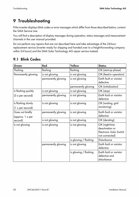
9.1 Blink CodesGreen Red Yellow StatusFlashing flashing flashing OK (start-up phase)Permanently glowing is not glowing is not glowing OK (feed-in operation)
permanently glowing is not glowing Earth fault or varistor defective
permanently glowing OK (initialisation)Is flashing quickly(3 x per second)
is not glowing is not glowing OK (stop)permanently glowing is not glowing Earth fault or varistor
defectiveIs flashing slowly(1 x per second)
is not glowing is not glowing OK (waiting, grid monitoring)
Goes out briefly(approx. 1 x per second)
permanently glowing is not glowing Earth fault or varistor defective
is not glowing is not glowing OK (derating)Is not glowing is not glowing is not glowing OK (night-time
deactivation or Electronic Solar Switch not connected)
is glowing / flashing Disturbancepermanently glowing is not glowing Earth fault or varistor
defectiveis glowing / flashing Earth fault or varistor
defective and disturbance

SMA Solar Technology AG Troubleshooting
Installation Manual SMC46-60A11-IA-en-81 59
9.2 Error MessagesIf a disturbance occurs, the inverter generates a message which depends on the operating mode and the type of the disturbance detected.Message Description and corrective measure!PV-Overvoltage!!DISCONNECT DC!
Overvoltage at the DC input.Overvoltage can destroy the inverter.Corrective measuresImmediately disconnect the inverter from the electricity grid.1. Disconnect the miniature circuit-breaker.2. Remove the Electronic Solar Switch.3. Remove all DC connectors.4. Check the DC voltage:
– If the DC voltage is above the maximum input voltage, check the PV plant design or contact the PV array installer.
– If the DC voltage is below the maximum input voltage, reconnect the inverter to the PV array as described in Section 5.4.4 "Connecting the PV Array (DC)" (page 31).
If the message occurs again, disconnect the inverter again and contact the SMA Service Line (see Section 13 "Contact" (page 80)).
ACVtgRPro The 10-minute average mains voltage is no longer within the permissible range. This can be caused by one of the following:
• The mains voltage at the termination point is too high.• The grid impedance at the termination point is too high.
The inverter disconnects from the grid to maintain power quality. Corrective measuresCheck the mains voltage at the termination point of the inverter:
• If, due to the local grid conditions, the mains voltage is 253 V or more, ask the network operator whether the voltage at the feed-in point can be adjusted, or whether they would agree to an alteration of the limiting value of parameter "ACVtgRPro" for power quality monitoring.
• If the mains voltage is continually within the tolerance range and this error message is still displayed, contact the SMA Service Line.
Bfr-Srr Internal measurement comparison fault or hardware defect. Corrective measures
• Contact the SMA Service Line if this disturbance occurs frequently.
Troubleshooting SMA Solar Technology AG
60 SMC46-60A11-IA-en-81 Installation Manual
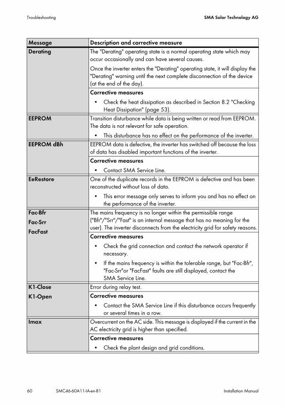
Derating The "Derating" operating state is a normal operating state which may occur occasionally and can have several causes. Once the inverter enters the "Derating" operating state, it will display the "Derating" warning until the next complete disconnection of the device (at the end of the day). Corrective measures
• Check the heat dissipation as described in Section 8.2 "Checking Heat Dissipation" (page 53).
EEPROM Transition disturbance while data is being written or read from EEPROM. The data is not relevant for safe operation.
• This disturbance has no effect on the performance of the inverter.EEPROM dBh EEPROM data is defective, the inverter has switched off because the loss
of data has disabled important functions of the inverter.Corrective measures
• Contact SMA Service Line.EeRestore One of the duplicate records in the EEPROM is defective and has been
reconstructed without loss of data.• This error message only serves to inform you and has no effect on
the performance of the inverter.Fac-BfrFac-SrrFacFast
The mains frequency is no longer within the permissible range ("Bfr"/"Srr"/"Fast" is an internal message that has no meaning for the user). The inverter disconnects from the electricity grid for safety reasons.Corrective measures
• Check the grid connection and contact the network operator if necessary.
• If the mains frequency is within the tolerable range, but "Fac-Bfr", "Fac-Srr"or "FacFast" faults are still displayed, contact the SMA Service Line.
K1-CloseK1-Open
Error during relay test.Corrective measures
• Contact the SMA Service Line if this disturbance occurs frequently or several times in a row.
Imax Overcurrent on the AC side. This message is displayed if the current in the AC electricity grid is higher than specified. Corrective measures
• Check the plant design and grid conditions.
Message Description and corrective measure
SMA Solar Technology AG Troubleshooting
Installation Manual SMC46-60A11-IA-en-81 61
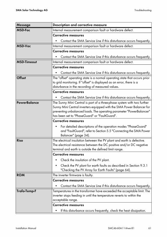
MSD-Fac Internal measurement comparison fault or hardware defect. Corrective measures
• Contact the SMA Service Line if this disturbance occurs frequently.MSD-Vac Internal measurement comparison fault or hardware defect.
Corrective measures• Contact the SMA Service Line if this disturbance occurs frequently.
MSD-Timeout Internal measurement comparison fault or hardware defect. Corrective measures
• Contact the SMA Service Line if this disturbance occurs frequently.Offset The "offset" operating state is a normal operating state that occurs prior
to grid monitoring. If "offset" is displayed as an error, there is a disturbance in the recording of measured values.Corrective measures
• Contact the SMA Service Line if this disturbance occurs frequently.PowerBalance The Sunny Mini Central is part of a three-phase system with two further
Sunny Mini Central inverters equipped with the SMA Power Balancer for preventing unbalanced loads. The operating parameter "PowerBalancer" has been set to "PhaseGuard" or "FaultGuard". Corrective measures
• For detailed descriptions of the operation modes "PhaseGuard" and "FaultGuard", refer to Section 5.5 "Connecting the SMA Power Balancer" (page 34).
Riso The electrical insulation between the PV plant and earth is defective. The electrical resistance between the DC positive and/or DC negative terminal and earth is outside the defined limit range. Corrective measures
• Check the insulation of the PV plant.• Check the PV plant for earth faults as described in Section 9.3.1
"Checking the PV Array for Earth Faults" (page 64).ROM The inverter firmware is faulty.
Corrective measures• Contact the SMA Service Line if this disturbance occurs frequently.
Trafo-Temp-F Temperatures in the transformer have exceeded the acceptable limit. The inverter stops feeding in until the temperature reverts to within the acceptable range.Corrective measures
• If this disturbance occurs frequently, check the heat dissipation.
Message Description and corrective measure

Troubleshooting SMA Solar Technology AG
62 SMC46-60A11-IA-en-81 Installation Manual
Trafo-Temp-W If the transformer temperature has risen above the acceptable level, the inverter stops feeding in until the temperature has reverted to an acceptable level and the feed-in operation can be resumed. The "Trafo-Temp-W" warning is displayed until the device is completely disconnected.Corrective measures
• Check the heat dissipation of the inverter.Shutdown Temporary inverter disturbance.
Corrective measures• Contact SMA Service Line.
Vac-BfrVac-Srr
The mains voltage is no longer within the permissible range ("Bfr" or "Srr" is an internal message of no relevance for the user). This disturbance can be caused by any of the following conditions:
• electricity grid disconnected (miniature circuit-breaker, fuse),• AC cable is interrupted or• AC cable is highly resistive.
The inverter disconnects from the electricity grid for safety reasons.Corrective measures
• Check the mains voltage and grid connection on the inverter. • If the mains voltage lies outside the acceptable range because of
local grid conditions, ask the network operator if the voltages can be adjusted at the feed-in point or if they agree to changes in the values of the monitored operating limits (operating parameters: Vac-Min and Vac-Max).
• If the mains voltage lies within the tolerance range, yet "Vac-Bfr" or "Vac-Srr" faults are still displayed, contact the SMA Service Line.
Message Description and corrective measure
SMA Solar Technology AG Troubleshooting
Installation Manual SMC46-60A11-IA-en-81 63
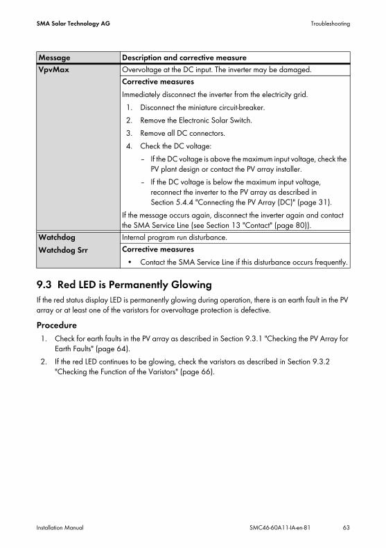
9.3 Red LED is Permanently GlowingIf the red status display LED is permanently glowing during operation, there is an earth fault in the PV array or at least one of the varistors for overvoltage protection is defective.Procedure1. Check for earth faults in the PV array as described in Section 9.3.1 "Checking the PV Array for
Earth Faults" (page 64).2. If the red LED continues to be glowing, check the varistors as described in Section 9.3.2
"Checking the Function of the Varistors" (page 66).
VpvMax Overvoltage at the DC input. The inverter may be damaged.Corrective measuresImmediately disconnect the inverter from the electricity grid.1. Disconnect the miniature circuit-breaker.2. Remove the Electronic Solar Switch.3. Remove all DC connectors.4. Check the DC voltage:
– If the DC voltage is above the maximum input voltage, check the PV plant design or contact the PV array installer.
– If the DC voltage is below the maximum input voltage, reconnect the inverter to the PV array as described in Section 5.4.4 "Connecting the PV Array (DC)" (page 31).
If the message occurs again, disconnect the inverter again and contact the SMA Service Line (see Section 13 "Contact" (page 80)).
WatchdogWatchdog Srr
Internal program run disturbance. Corrective measures
• Contact the SMA Service Line if this disturbance occurs frequently.
Message Description and corrective measure

Troubleshooting SMA Solar Technology AG
64 SMC46-60A11-IA-en-81 Installation Manual
9.3.1 Checking the PV Array for Earth Faults1. Disconnect the inverter from both the DC and AC sides as described in Section 7.2 "Opening
the Inverter" (page 48).
2. Measure the voltages between the positive pole of each string and the earth potential (PE).
3. Measure the voltages between the negative pole of each string and the earth potential (PE).
4. Measure the voltages between the positive and negative poles of each string.
An earth fault is present if the measured voltages are stable and the sum of the voltages of the positive pole against earth potential and the negative pole against earth potential of a string is approximately equal to the voltage between the positive and negative poles.
DANGER!Danger to life due to electric shock
• Only touch the insulation of the PV array cables.• Do not connect strings with earth faults to the inverter.
NOTICE!Excessive voltages can destroy the multimeter
• Only use multimeters with a DC input voltage range of up to at least 1,000 V.
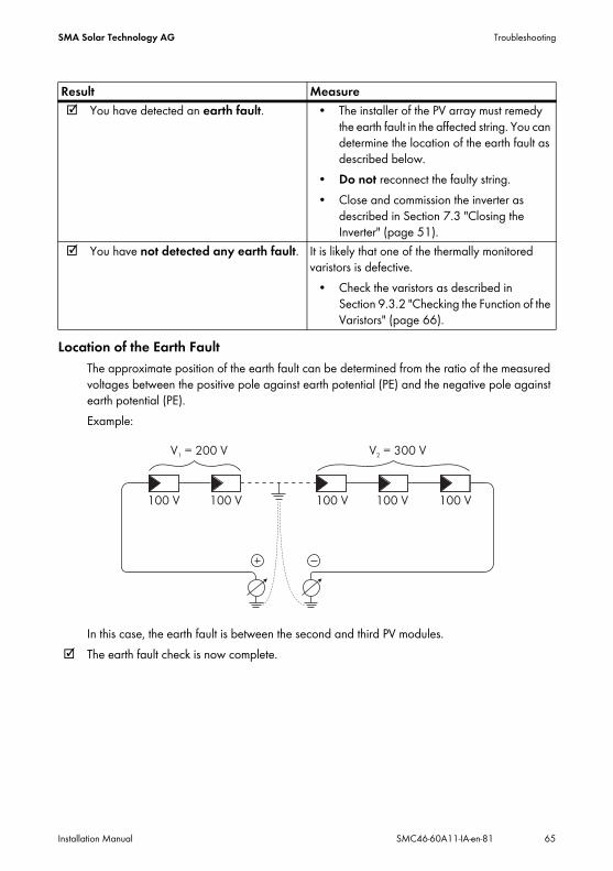
SMA Solar Technology AG Troubleshooting
Installation Manual SMC46-60A11-IA-en-81 65
Location of the Earth FaultThe approximate position of the earth fault can be determined from the ratio of the measured voltages between the positive pole against earth potential (PE) and the negative pole against earth potential (PE).Example:
In this case, the earth fault is between the second and third PV modules. The earth fault check is now complete.
Result Measure You have detected an earth fault. • The installer of the PV array must remedy
the earth fault in the affected string. You can determine the location of the earth fault as described below.
• Do not reconnect the faulty string.• Close and commission the inverter as
described in Section 7.3 "Closing the Inverter" (page 51).
You have not detected any earth fault. It is likely that one of the thermally monitored varistors is defective.
• Check the varistors as described in Section 9.3.2 "Checking the Function of the Varistors" (page 66).

Troubleshooting SMA Solar Technology AG
66 SMC46-60A11-IA-en-81 Installation Manual
9.3.2 Checking the Function of the VaristorsVaristors are wear parts, whose functional efficiency diminishes with age or following repeated responses as a result of overvoltages. It is therefore possible that one of the thermally monitored varistors has lost its protective function, and thus the red LED is glowing.
Check the function of the varistors as described below:1. Open the inverter as described in Section 7.2 "Opening the Inverter" (page 48).2. With the aid of a multimeter, determine for both
varistors in the installed state whether a conductive connection exists between connectors B and C.
Position of the varistorsYou can determine the position of the varistors using the illustration below.Note the following assignment of the terminals:
• Terminal A: outer terminal (varistor connection with loop)
• Terminal B: middle terminal• Terminal C: outer terminal
(varistor connection without loop)
Result Measure There is a conductive connection: Presumably there is a different error in the inverter.
• Contact the SMA Service Line (see Section 13 "Contact" (page 80)).
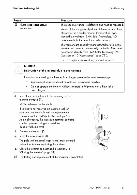
SMA Solar Technology AG Troubleshooting
Installation Manual SMC46-60A11-IA-en-81 67
3. Insert the insertion tool into the openings of the terminal contacts (1). This releases the terminals. If you have not received an insertion tool for operating the terminals with the replacement varistors, contact SMA Solar Technology AG. As an alternative, the individual terminal contacts can be operated using a screwdriver (blade width 3.5 mm).
4. Remove the varistor (2).5. Insert the new varistor (3).
The pole with the small loop (crimp) must be fitted to terminal A when replacing the varistor.
6. Close the inverter as described in Section 7.3 "Closing the Inverter" (page 51).
The testing and replacement of the varistors is completed.
There is no conductive connection:
The respective varistor is defective and must be replaced.Varistor failure is generally due to influences that affect all varistors in a similar manner (temperature, age, induced overvoltage). SMA Solar Technology AG recommends that you replace both varistors.The varistors are specially manufactured for use in the inverter and are not commercially available. They must be ordered directly from SMA Solar Technology AG (see Section 12 "Accessories" (page 79)).
• To replace the varistors, proceed to step 3.NOTICE!Destruction of the inverter due to overvoltage
If varistors are missing, the inverter is no longer protected against overvoltages. • Replacement varistors should be obtained as soon as possible.• Do not operate the inverter without varistors in PV plants with a high risk of
overvoltages.
Result Measure

Decommissioning SMA Solar Technology AG
68 SMC46-60A11-IA-en-81 Installation Manual
10 Decommissioning10.1 Dismounting the Inverter1. Open the inverter as described in Section 7.2 "Opening the Inverter" (page 48).2. Remove all cables from the inverter.3. Close the inverter using the six screws and the
corresponding conical spring washers.
4. Remove the ventilation grids from both sides.
5. Remove the two screws on the left- and right-hand sides of the inverter that attach it to the wall mounting bracket.
6. Disconnect the anti-theft protection if applicable.
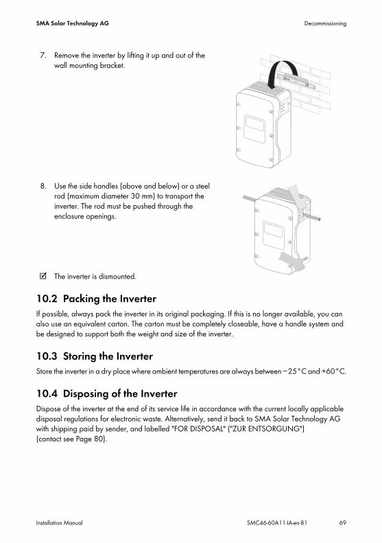
SMA Solar Technology AG Decommissioning
Installation Manual SMC46-60A11-IA-en-81 69
7. Remove the inverter by lifting it up and out of the wall mounting bracket.
8. Use the side handles (above and below) or a steel rod (maximum diameter 30 mm) to transport the inverter. The rod must be pushed through the enclosure openings.
The inverter is dismounted.
10.2 Packing the InverterIf possible, always pack the inverter in its original packaging. If this is no longer available, you can also use an equivalent carton. The carton must be completely closeable, have a handle system and be designed to support both the weight and size of the inverter.
10.3 Storing the InverterStore the inverter in a dry place where ambient temperatures are always between −25°C and +60°C.
10.4 Disposing of the InverterDispose of the inverter at the end of its service life in accordance with the current locally applicable disposal regulations for electronic waste. Alternatively, send it back to SMA Solar Technology AG with shipping paid by sender, and labelled "FOR DISPOSAL" ("ZUR ENTSORGUNG") (contact see Page 80).
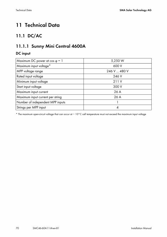
Technical Data SMA Solar Technology AG
70 SMC46-60A11-IA-en-81 Installation Manual
11 Technical Data11.1 DC/AC
11.1.1 Sunny Mini Central 4600ADC input
* The maximum open-circuit voltage that can occur at − 10°C cell temperature must not exceed the maximum input voltage
Maximum DC power at cos φ = 1 5,250 WMaximum input voltage* 600 VMPP voltage range 246 V ... 480 VRated input voltage 246 VMinimum input voltage 211 VStart input voltage 300 VMaximum input current 26 AMaximum input current per string 26 ANumber of independent MPP inputs 1Strings per MPP input 4

SMA Solar Technology AG Technical Data
Installation Manual SMC46-60A11-IA-en-81 71
AC Output
* 4,600 VA with VDE-AR-N-4105** Applies to SMC 4600A-11*** Applies to SMC 4600A
Efficiency
Rated power at 230 V, 50 Hz 4,600 WMaximum apparent AC power* 5,000 VARated grid voltage 230 VAC nominal voltage 220 V / 230 V / 240 VAC voltage range 160 V ... 265 VNominal AC current at 220 V 20.9 ANominal AC current at 230 V 20.0 ANominal AC current at 240 V 19.16 AMaximum output current 26 ATotal harmonic factor of the output current with AC voltage < 2% and AC power > 50% of the rated power
≤ 3%
Rated mains frequency 50 HzAC mains frequency 50 Hz/60 HzOperating range at AC mains frequency of 50 Hz
44 Hz … 55 Hz
Operating range at AC mains frequency of 60 Hz
54 Hz … 65 Hz
Displacement power factor, adjustable** 0.8overexcited … 0.8underexcitedPower factor at nominal AC power*** 1Feed-in phases 1Connection phases 1Overvoltage category according to IEC 60664-1
III
Maximum efficiency, ηmax 96.1%European weighted efficiency, ηEU 95.3%

Technical Data SMA Solar Technology AG
72 SMC46-60A11-IA-en-81 Installation Manual
11.1.2 Sunny Mini Central 5000ADC input
* The maximum open-circuit voltage that can occur at a cell temperature of − 10°C must not exceed the maximum input voltage.
Maximum DC power at cos φ = 1 5,750 WMaximum input voltage* 600 VMPP voltage range 246 V ... 480 VRated input voltage 246 VMinimum input voltage 211 VStart input voltage 300 VMaximum input current 26 AMaximum input current per string 26 ANumber of independent MPP inputs 1Strings per MPP input 4

SMA Solar Technology AG Technical Data
Installation Manual SMC46-60A11-IA-en-81 73
AC Output
* Applies to SMC 5000A-11** Applies to SMC 5000A
Efficiency
Rated power at 230 V, 50 Hz 5,000 WMaximum apparent AC power 5,500 VARated grid voltage 230 VAC nominal voltage 220 V / 230 V / 240 VAC voltage range 160 V ... 265 VNominal AC current at 220 V 22.7 ANominal AC current at 230 V 21.7 ANominal AC current at 240 V 20.8 AMaximum output current 26 ATotal harmonic factor of the output current with AC voltage < 2% and AC power > 50% of the rated power
≤ 3%
Rated mains frequency 50 HzAC mains frequency 50 Hz/60 HzOperating range at AC mains frequency of 50 Hz
44 Hz … 55 Hz
Operating range at AC mains frequency of 60 Hz
54 Hz … 65 Hz
Displacement power factor, adjustable* 0.8overexcited … 0.8underexcitedPower factor at nominal AC power** 1Feed-in phases 1Connection phases 1Overvoltage category according to IEC 60664-1
III
Maximum efficiency, ηmax 96.1%European weighted efficiency, ηEU 95.3%

Technical Data SMA Solar Technology AG
74 SMC46-60A11-IA-en-81 Installation Manual
11.1.3 Sunny Mini Central 6000ADC input
* The maximum open-circuit voltage that can occur with − 10°C cell temperature must not exceed the maximum input voltage.
Maximum DC power at cos φ = 1 6,300 WMaximum input voltage* 600 VMPP voltage range 246 V ... 480 VRated input voltage 246 VMinimum input voltage 211 VStart input voltage 300 VMaximum input current 26 AMaximum input current per string 26 ANumber of independent MPP inputs 1Strings per MPP input 4

SMA Solar Technology AG Technical Data
Installation Manual SMC46-60A11-IA-en-81 75
AC Output
* Applies to SMC 6000A-11** Applies to SMC 6000A
Efficiency
Rated power at 230 V, 50 Hz 6,000 WMaximum apparent AC power 6,000 VARated grid voltage 230 VAC nominal voltage 220 V / 230 V / 240 VAC voltage range 160 V ... 265 VNominal AC current at 230 V 26 ANominal AC current at 240 V 25 AMaximum output current 26 ATotal harmonic factor of the output current with AC voltage < 2% and AC power > 50% of the rated power
≤ 3%
Rated mains frequency 50 HzAC mains frequency 50 Hz/60 HzOperating range at AC mains frequency of 50 Hz
44 Hz … 55 Hz
Operating range at AC mains frequency of 60 Hz
54 Hz … 65 Hz
Displacement power factor, adjustable* 0.8overexcited … 0.8underexcitedPower factor at nominal AC power** 1Feed-in phases 1Connection phases 1Overvoltage category according to IEC 60664-1
III
Maximum efficiency, ηmax 96.1%European weighted efficiency, ηEU 95.3%

Technical Data SMA Solar Technology AG
76 SMC46-60A11-IA-en-81 Installation Manual
11.2 General Data
11.3 Protective Devices
Width x height x depth with Electronic Solar Switch
468 mm x 613 mm x 242 mm
Weight 63 kgLength x width x height of packaging 396 mm x 803 mm x 596 mmTransport weight 68 kgClimatic class as per IEC 60721-2-1 4K4HOperating temperature range − 25°C ... +60°CMaximum permissible value for relative humidity, non-condensing
100%
Maximum operating altitude above MSL 2,000 mNoise emission (typical) ≤ 42 dB(A)Power loss in night operation 0.25 WTopology LF transformerCooling concept OptiCoolFan connection designed as safe disconnection in accordance
with DIN EN 50178:1998-04Degree of protection for electronics according to IEC 60529
IP65
Protection class according to IEC 62103 I
DC reverse polarity protection short-circuit diodeInput-side disconnection device Electronic Solar SwitchDC overvoltage protection thermally monitored varistorsAC short-circuit current capability current controlGrid monitoring SMA Grid Guard 2.1Maximum permissible fuse protection 40 AEarth fault monitoring Insulation monitoring: Riso > 1 MΩGalvanic isolation available

SMA Solar Technology AG Technical Data
Installation Manual SMC46-60A11-IA-en-81 77
11.4 Approvals
* EN 50438: not applicable to all deviations from the national standard In planning stage
11.5 Climatic ConditionsAccording to IEC 60721-3-4, Installation type C, Class 4K4H
According to IEC 60721-3-4, Transport type E, Class 2K3
Country standard, as of 07/2012
SMC
4600
A-11
SMC
5000
A-11
SMC
6000
A-11
SMC
4600
A
SMC
5000
A
SMC
6000
A
VDE0126-1-1 VDE-AR-N-4105 ‒ ‒ ‒AS 4777 ‒ C10/11 ‒ ‒ ‒PPDS GBT19939-2005 VDE0126-1-1/UTE C15-712-1
UTE C15-712-1/EDF SEI req.
PPC SI 4777 CEI 0-21 ‒ ‒ ‒ ‒ ‒EN 50438* RD 1699 ‒ ‒ ‒RD 661/2007 IEC 61727 PEA ‒ ‒ ‒ ‒ G83/1-1 ‒ ‒ ‒ G59/2 ‒ ‒ ‒
Extended temperature range − 25°C ... +60°CExtended humidity range 0% … 100%Extended air pressure range 79.5 kPa … 106 kPa
Temperature range − 25°C ... +70°C
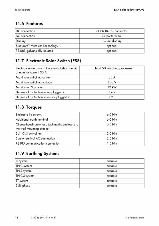
Technical Data SMA Solar Technology AG
78 SMC46-60A11-IA-en-81 Installation Manual
11.6 Features
11.7 Electronic Solar Switch (ESS)
11.8 Torques
11.9 Earthing Systems
DC connection SUNCLIX DC connectorAC connection Screw terminalDisplay LC text displayBluetooth® Wireless Technology optionalRS485, galvanically isolated optional
Electrical endurance in the event of short circuit, at nominal current 35 A
at least 50 switching processes
Maximum switching current 35 AMaximum switching voltage 800 VMaximum PV power 12 kWDegree of protection when plugged in IP65Degree of protection when not plugged in IP21
Enclosure lid screws 6.0 NmAdditional earth terminal 6.0 NmCheese-head screw for attaching the enclosure to the wall mounting bracket
6.0 Nm
SUNCLIX swivel nut 2.0 NmScrew terminal AC connection 2.5 NmRS485 communication connection 1.5 Nm
IT system suitableTN-C system suitableTN-S system suitableTN-C-S system suitableTT system suitableSplit phase suitable

SMA Solar Technology AG Accessories
Installation Manual SMC46-60A11-IA-en-81 79
12 AccessoriesYou will find the corresponding accessories and spare parts for your product in the following overview. If required, you can order these from SMA Solar Technology AG or your specialist dealer.Description Brief description SMA order numberBluetooth retrofit kit Bluetooth communication interface BTPBINV-NRInsertion tool for replacement of varistors
Insertion tool for varistors SB-TVWZ
Electronic Solar Switch ESS handle (spare) ESS-HANDLE:04Also indicate the
inverter serial number.Negative earthing set Retrofit kit for the negative earthing of the DC
inputESHV-N-NR
Positive earthing set Retrofit kit for the positive earthing of the DC input ESHV-P-NRReplacement varistors Set of thermally monitored varistors (2) incl.
insertion toolSB-TV4
Radio retrofit kit Radio Piggy-Back for retrofitting an inverter for communication with Sunny Beam, including antenna, coaxial cable, and PG cable gland (metal)
BEAMPB-NR
Ventilation grid Ventilation grid set "right and left" as spare parts 45-7202Power Balancer plug Retrofit kit for retrofitting a Sunny Mini Central
equipped with an SMA Power Balancer to the SMA Power Balancer plug-in system
PBL-SMC-10-NR
RS485 retrofit kit RS485 interface 485PB-SMC-NRSMA Power Balancer Y-cable
Connecting cable (2 x 2 m) for SMA Power Balancer plug-in system
PBL-YCABLE-10
SUNCLIX DC connector Field plug for conductor cross-sections of 2.5 mm² … 6 mm²
SUNCLIX-FC6-SET
Contact SMA Solar Technology AG
80 SMC46-60A11-IA-en-81 Installation Manual
13 ContactIf you have technical problems concerning our products, please contact the SMA Service Line. We require the following information in order to provide you with the necessary assistance:
• Inverter type• Inverter serial number• Type and number of the PV modules connected• Optional equipment, e.g. communication products• Blink code or inverter display message
SMA Solar Technology AGSonnenallee 134266 Niestetal, Germanywww.SMA.de
SMA Service LineInverters +49 561 9522 1499Communication: +49 561 9522 2499Fax: +49 561 9522 4699E‑Mail: [email protected]


SMA Solar Technology AG Legal Provisions
Installation Manual SMC46-60A11-IA-en-81 83
Legal ProvisionsThe information contained in this document is the property of SMA Solar Technology AG. Publishing its content, either partially or in full, requires the written permission of SMA Solar Technology AG. Any internal company copying of the document for the purposes of evaluating the product or its correct implementation is allowed and does not require permission.
SMA Factory WarrantyThe current warranty conditions come enclosed with your device. These are also available online at www.SMA-Solar.com and can be downloaded and are available on paper from the usual sales channels if required.
TrademarksAll trademarks are recognized even if these are not marked separately. Missing designations do not mean that a product or brand is not a registered trademark.The Bluetooth® word mark and logos are registered trademarks owned by Bluetooth SIG, Inc. and any use of such marks by SMA Solar Technology AG is under licence.QR Code® is a registered trademark of DENSO WAVE INCORPORATED.
SMA Solar Technology AGSonnenallee 134266 NiestetalGermanyTel. +49 561 9522-0Fax +49 561 9522-100www.SMA.deE-Mail: [email protected]© 2004 to 2012 SMA Solar Technology AG. All rights reserved